

Endress+Hauser Proline t-mass 65, Prolinet-mass F, Proline t-mass I Operating Instructions Manual
Page 1
Operating Instructions
Proline t-mass 65
PROFIBUS DP/PA
Thermal Mass Flow Measuring System
8
BA00113D/06/EN/13.10
71123860
Valid as of version
PROFIBUS DP
V 3.06.XX (Device software)
PROFIBUS PA
V 3.06.XX (Device software)
Page 2

Page 3

Proline t-mass 65 PROFIBUS DP/PA Table of contents
Table of contents
1 Safety instructions . . . . . . . . . . . . . . . . 5
1.1 Designated use . . . . . . . . . . . . . . . . . . . . . . . . . . . . 5
1.2 Installation, commissioning and operation . . . . . . . . 5
1.3 Operational safety . . . . . . . . . . . . . . . . . . . . . . . . . . 6
1.4 Return . . . . . . . . . . . . . . . . . . . . . . . . . . . . . . . . . . . 6
1.5 Notes on safety conventions and icons . . . . . . . . . . . 6
2 Identification . . . . . . . . . . . . . . . . . . . . 7
2.1 Device designation . . . . . . . . . . . . . . . . . . . . . . . . . 7
2.1.1 Nameplate of the transmitter . . . . . . . . . . . . 7
2.1.2 Nameplate of the sensor . . . . . . . . . . . . . . . 8
2.1.3 Nameplate for connections . . . . . . . . . . . . . 9
2.2 Certificates and approvals . . . . . . . . . . . . . . . . . . . 10
2.3 Registered trademarks . . . . . . . . . . . . . . . . . . . . . . 10
3 Installation . . . . . . . . . . . . . . . . . . . . . 11
3.1 Incoming acceptance, transport and storage . . . . . . 11
3.1.1 Incoming acceptance . . . . . . . . . . . . . . . . . 11
3.1.2 Transport . . . . . . . . . . . . . . . . . . . . . . . . . 11
3.1.3 Storage . . . . . . . . . . . . . . . . . . . . . . . . . . . 11
3.2 Installation conditions . . . . . . . . . . . . . . . . . . . . . . 12
3.2.1 Dimensions . . . . . . . . . . . . . . . . . . . . . . . . 12
3.2.2 System pressure and pulsating flow . . . . . . 12
3.2.3 Pipework requirements . . . . . . . . . . . . . . . 13
3.2.4 Orientation . . . . . . . . . . . . . . . . . . . . . . . . 14
3.2.5 Inlet and outlet runs . . . . . . . . . . . . . . . . . 15
3.2.6 Heating . . . . . . . . . . . . . . . . . . . . . . . . . . . 18
3.2.7 Thermal insulation . . . . . . . . . . . . . . . . . . 18
3.2.8 Vibrations . . . . . . . . . . . . . . . . . . . . . . . . . 18
3.3 Installation instructions . . . . . . . . . . . . . . . . . . . . . 19
3.3.1 Mounting the insertion sensor . . . . . . . . . . 19
3.3.2 Removing the insertion sensor . . . . . . . . . . 22
3.3.3 Mounting the flanged sensor . . . . . . . . . . . 22
3.3.4 Turning the transmitter housing . . . . . . . . 23
3.3.5 Turning the local display . . . . . . . . . . . . . . 23
3.3.6 Installing the wall-mount
transmitter housing . . . . . . . . . . . . . . . . . . 24
3.4 Post-installation check . . . . . . . . . . . . . . . . . . . . . . 26
4 Wiring . . . . . . . . . . . . . . . . . . . . . . . . 27
4.1 Cable specifications . . . . . . . . . . . . . . . . . . . . . . . . 27
4.1.1 PROFIBUS DP cable specifications . . . . . . . 27
4.1.2 Shielding and grounding . . . . . . . . . . . . . . 28
4.2 Connecting the remote version . . . . . . . . . . . . . . . 29
4.2.1 Connecting connecting cable for
sensor/transmitter . . . . . . . . . . . . . . . . . . . 29
4.2.2 Cable specification, connecting cable . . . . . 29
4.3 Connecting the measuring unit . . . . . . . . . . . . . . . 30
4.3.1 Terminal assignment . . . . . . . . . . . . . . . . . 30
4.3.2 Transmitter connection . . . . . . . . . . . . . . . 30
4.3.3 PROFIBUS DP connection diagram . . . . . . 31
4.3.4 PROFIBUS PA connection diagram . . . . . . 32
4.4 Degree of protection . . . . . . . . . . . . . . . . . . . . . . . 34
4.5 Post-connection check . . . . . . . . . . . . . . . . . . . . . . 35
5 Operation . . . . . . . . . . . . . . . . . . . . . . 36
5.1 Quick operation guide . . . . . . . . . . . . . . . . . . . . . . 36
5.2 Local display . . . . . . . . . . . . . . . . . . . . . . . . . . . . . 37
5.2.1 Display and operating elements . . . . . . . . . 37
5.2.2 Icons . . . . . . . . . . . . . . . . . . . . . . . . . . . . . 37
5.3 Brief operating instructions to the function matrix . 38
5.3.1 General notes . . . . . . . . . . . . . . . . . . . . . . 39
5.3.2 Enabling the programming mode . . . . . . . . 39
5.3.3 Disabling the programming mode . . . . . . . . 39
5.4 Error messages . . . . . . . . . . . . . . . . . . . . . . . . . . . . 40
5.4.1 Type of error . . . . . . . . . . . . . . . . . . . . . . . 40
5.4.2 Error message type . . . . . . . . . . . . . . . . . . . 40
5.5 Operating options . . . . . . . . . . . . . . . . . . . . . . . . . 41
5.5.1 FieldCare . . . . . . . . . . . . . . . . . . . . . . . . . . 41
5.5.2 Operating program
"SIMATIC PDM" (Siemens) . . . . . . . . . . . . 41
5.5.3 Current device description files . . . . . . . . . 41
5.6 PROFIBUS DP hardware settings . . . . . . . . . . . . . 43
5.6.1 Configuring the write protection . . . . . . . . 43
5.6.2 Configuring the device address . . . . . . . . . . 44
5.6.3 Configuring the terminating resistors . . . . . 45
5.7 PROFIBUS PA hardware settings . . . . . . . . . . . . . . 46
5.7.1 Configuring the write protection . . . . . . . . 46
5.7.2 Configuring the device address . . . . . . . . . . 47
6 Commissioning . . . . . . . . . . . . . . . . . . 48
6.1 Function check . . . . . . . . . . . . . . . . . . . . . . . . . . . 48
6.2 Switching on the measuring device . . . . . . . . . . . . 48
6.3 Quick Setup . . . . . . . . . . . . . . . . . . . . . . . . . . . . . . 48
6.3.1 Quick Setup "Commissioning" . . . . . . . . . . 49
6.3.2 Quick Setup "Sensor" . . . . . . . . . . . . . . . . . 51
6.3.3 "Gas" Quick Setup menu . . . . . . . . . . . . . . 52
6.3.4 "Pressure" Quick Setup menu . . . . . . . . . . . 54
6.3.5 "Heat Flow" Quick Setup menu . . . . . . . . . 55
6.3.6 Quick Setup "Communication" . . . . . . . . . . 57
6.3.7 Data backup/transmission . . . . . . . . . . . . . 58
6.4 Commissioning the PROFIBUS interface . . . . . . . . . 59
6.4.1 PROFIBUS DP/PA commissioning . . . . . . 59
6.5 PROFIBUS DP/PA system integration . . . . . . . . . . 61
6.5.1 Device master file (GSD file) . . . . . . . . . . . 61
6.5.2 Example for selecting the GSD file . . . . . . . 63
6.5.3 Maximum number of writes . . . . . . . . . . . 63
6.6 PROFIBUS DP cyclic data transmission . . . . . . . . . . 64
6.6.1 Block model . . . . . . . . . . . . . . . . . . . . . . . 64
6.6.2 Modules for cyclic data transmission . . . . . 65
6.6.3 Description of the modules . . . . . . . . . . . . 66
6.6.4 Configuration examples with
Simatic S7 HW-Konfig . . . . . . . . . . . . . . . . 71
6.7 PROFIBUS PA cyclic data transmission . . . . . . . . . . 73
6.7.1 Block model . . . . . . . . . . . . . . . . . . . . . . . 73
6.7.2 Modules for cyclic data transmission . . . . . 74
6.7.3 Description of the modules . . . . . . . . . . . . 75
6.7.4 Configuration examples with
Simatic S7 HW-Konfig . . . . . . . . . . . . . . . . 80
Endress+Hauser 3
Page 4

Proline t-mass 65 PROFIBUS DP/PA Table of contents
6.8 PROFIBUS DP/PA acyclic data transmission . . . . . 82
6.8.1 Master class 2 acyclic (MS2AC) . . . . . . . . . 82
6.8.2 Master class 1 acyclic (MS1AC) . . . . . . . . . 82
6.9 Adjustment . . . . . . . . . . . . . . . . . . . . . . . . . . . . . . 83
6.9.1 Zero point adjustment . . . . . . . . . . . . . . . . 83
6.10 Data storage device (HistoROM) . . . . . . . . . . . . . . 84
6.10.1 HistoROM/S-DAT (sensor-DAT) . . . . . . . . 84
6.10.2 HistoROM/T-DAT (transmitter-DAT) . . . . 84
7 Maintenance . . . . . . . . . . . . . . . . . . . . 85
7.1 External cleaning . . . . . . . . . . . . . . . . . . . . . . . . . 85
7.2 Pipe cleaning . . . . . . . . . . . . . . . . . . . . . . . . . . . . . 85
7.3 Transducer cleaning . . . . . . . . . . . . . . . . . . . . . . . 85
7.4 Replacing seals . . . . . . . . . . . . . . . . . . . . . . . . . . . 86
7.5 In-situ calibration . . . . . . . . . . . . . . . . . . . . . . . . . 86
7.6 Recalibration . . . . . . . . . . . . . . . . . . . . . . . . . . . . . 86
8 Accessories . . . . . . . . . . . . . . . . . . . . . 87
8.1 Device-specific accessories . . . . . . . . . . . . . . . . . . . 87
8.2 Measuring principle-specific accessories . . . . . . . . . 87
8.3 Service-specific accessories . . . . . . . . . . . . . . . . . . 88
9 Trouble-shooting . . . . . . . . . . . . . . . . . 89
Index . . . . . . . . . . . . . . . . . . . . . . . . . . . . . 117
9.1 Trouble-shooting instructions . . . . . . . . . . . . . . . . . 89
9.2 System error messages . . . . . . . . . . . . . . . . . . . . . . 90
9.2.1 Displaying the device status on
PROFIBUS DP . . . . . . . . . . . . . . . . . . . . . . 90
9.2.2 List of system error messages . . . . . . . . . . 92
9.3 Process error messages . . . . . . . . . . . . . . . . . . . . . . 97
9.3.1 List of process error messages . . . . . . . . . . 97
9.4 Process errors without messages . . . . . . . . . . . . . . 97
9.5 Spare parts . . . . . . . . . . . . . . . . . . . . . . . . . . . . . . 99
9.5.1 Removing and installing printed
circuit boards . . . . . . . . . . . . . . . . . . . . . . 100
9.5.2 Replacing the device fuse . . . . . . . . . . . . . 105
9.6 Return . . . . . . . . . . . . . . . . . . . . . . . . . . . . . . . . . 106
9.7 Disposal . . . . . . . . . . . . . . . . . . . . . . . . . . . . . . . 106
9.8 Software history . . . . . . . . . . . . . . . . . . . . . . . . . 106
10 Technical data . . . . . . . . . . . . . . . . . . 107
10.1 Technical data at a glance . . . . . . . . . . . . . . . . . . 107
10.1.1 Applications . . . . . . . . . . . . . . . . . . . . . . . 107
10.1.2 Function and system design . . . . . . . . . . . 107
10.1.3 Input . . . . . . . . . . . . . . . . . . . . . . . . . . . . 107
10.1.4 Output . . . . . . . . . . . . . . . . . . . . . . . . . . 108
10.1.5 Power supply . . . . . . . . . . . . . . . . . . . . . . 109
10.1.6 Performance characteristics . . . . . . . . . . . 109
10.1.7 Operating conditions: Installation . . . . . . . 110
10.1.8 Operating conditions: Environment . . . . . 110
10.1.9 Operating conditions: Process . . . . . . . . . 111
10.1.10 Mechanical construction . . . . . . . . . . . . . 112
10.1.11 Human interface . . . . . . . . . . . . . . . . . . . 114
10.1.12 Certificates and approvals . . . . . . . . . . . . 114
10.1.13 Ordering information . . . . . . . . . . . . . . . 116
10.1.14 Accessories . . . . . . . . . . . . . . . . . . . . . . . 116
10.1.15 Documentation . . . . . . . . . . . . . . . . . . . 116
4 Endress+Hauser
Page 5

Proline t-mass 65 PROFIBUS DP/PA Safety instructions
1 Safety instructions
1.1 Designated use
The measuring device described in these Operating Instructions is to be used only for measuring the
mass flow rate of gases (e. g. kg, Nm
temperature. The measuring device can be configured to measure a standard range of pure gases or
gas mixtures.
Examples:
•Air
• Oxygen
• Nitrogen
• Carbon Dioxide
•Argon, etc.
The use with corrosive, saturated or unclean gases should be treated with caution (contact your
Endress+Hauser sales representative). The use with unstable gases or gases not deemed to be
suitable by Endress+Hauser must be avoided. The measuring device is not designed to be used with
liquids or fluids in the liquid phase.
Resulting from incorrect use or from use other than that designated, the operational safety of the
measuring devices can be jeopardized. The manufacturer accepts no liability for damages being
produced from this.
3
scf). At the same time, the system also measures gas
1.2 Installation, commissioning and operation
Note the following points:
• Installation, connection to the electricity supply, commissioning and maintenance of the device
must be carried out by trained, qualified specialists authorised to perform such work by the
facility's owner operator.
The specialist must have read and understood these Operating Instructions and must follow the
instructions they contain.
• The device must be operated by persons authorised and trained by the facility's owner-operator.
Strict compliance with the instructions in the Operating Instruction is mandatory.
• Endress+Hauser is willing to assist in clarifying the chemical resistance properties of parts wetted
by special fluids, including fluids used for cleaning. However small changes in temperature,
concentration or the degree of contamination in the process can result in changes of the chemical
resistance properties. Therefore, Endress+Hauser can not guarantee or accept liability for the
chemical resistance properties of the fluid wetted materials in a specific application. The user is
responsible for the choice of fluid wetted materials in regards to their in-process resistance to
corrosion.
• If carrying out welding work on the piping, the welding unit should not be grounded by means
of the measuring device.
• The installer must ensure that the measuring system is correctly wired in accordance with the
wiring diagrams. The transmitter must be earthed unless special protection measures have been
taken e.g. galvanically isolated power supply SELV or PELV! (SELV = Safe Extra Low Voltage;
PELV = Protective Extra Low Voltage)
• Invariably, local regulations governing the opening and repair of electrical devices apply.
Endress+Hauser 5
Page 6

Safety instructions Proline t-mass 65 PROFIBUS DP/PA
1.3 Operational safety
Note the following points:
• Measuring systems for use in hazardous environments are accompanied by separate "Ex
documentation", which is an integral part of these Operating Instructions. Strict compliance with
the installation instructions and ratings as stated in this supplementary documentation is
mandatory. The symbol on the front of this supplementary Ex documentation indicates the
approval and the certification body (e.g. 0 Europe, 2 USA, 1 Canada).
• When hot fluid passes through the measuring tube, the surface temperature of the housing
increases. In the case of the sensor, in particular, users should expect temperatures that can be
close to the fluid temperature. If the temperature of the fluid is high, implement sufficient
measures to prevent burning or scalding.
• The measuring device complies with the general safety requirements in accordance with
EN 61010-1, the EMC requirements of IEC/EN 61326, and NAMUR recommendation NE 21,
NE 43 and NE 53.
• The separate document on the Pressure Equipment Directive must be observed for devices used
in Category II or III installations in accordance with the Pressure Equipment Directive.
• The manufacturer reserves the right to modify technical data without prior notice. Your
Endress+Hauser distributor will supply you with current information and updates to these
Operating Instructions.
#
"
1.4 Return
• Do not return a measuring device if you are not absolutely certain that all traces of hazardous
substances have been removed, e.g. substances which have penetrated crevices or diffused
through plastic.
• Costs incurred for waste disposal and injury (burns, etc.) due to inadequate cleaning will be
charged to the owner-operator.
• Please note the measures on ä 106
1.5 Notes on safety conventions and icons
The devices are designed to meet state-of-the-art safety requirements, have been tested, and left the
factory in a condition in which they are safe to operate. The devices comply with the applicable
standards and regulations in accordance with EN 61010-1 "Protection Measures for Electrical
Equipment for Measurement, Control, Regulation and Laboratory Procedures". They can, however,
be a source of danger if used incorrectly or for other than the designated use.
Consequently, always pay particular attention to the safety instructions indicated in these Operating
Instructions by the following icons:
Warning!
"Warning" indicates an action or procedure which, if not performed correctly, can result in injury
or a safety hazard. Comply strictly with the instructions and proceed with care.
Caution!
"Caution" indicates an action or procedure which, if not performed correctly, can result in incorrect
operation or destruction of the device. Comply strictly with the instructions.
!
6 Endress+Hauser
Note!
"Note" indicates an action or procedure which, if not performed correctly, can have an indirect
effect on operation or trigger an unexpected response on the part of the device.
Page 7
Proline t-mass 65 PROFIBUS DP/PA Identification
1
2
3
4
7
8
Order Code:
Ser.No.:
TAG No.:
20-55VAC/16-62VDC
50-60Hz
14VA/8W
IP67/NEMA/Type4X65F25-XXXXXXXXXXXX
12345678901
ABCDEFGHJKLMNPQRST
–20°C (–4°F) < Tamb < +60°C (+140°F)
PROFIBUS DP (Profile 3.0)
Proline t-mass 65
Supply Ext. Termination
i
N12895
BPU S
R O IF
R
5
6
2 Identification
2.1 Device designation
The "t-mass 65" flow measuring system consists of the following components:
• t-mass 65 transmitter
• t-mass F, t-mass I sensors
Two versions are available:
• Compact version: transmitter and sensor form a single mechanical unit.
• Remote version: transmitter and sensor are installed separately
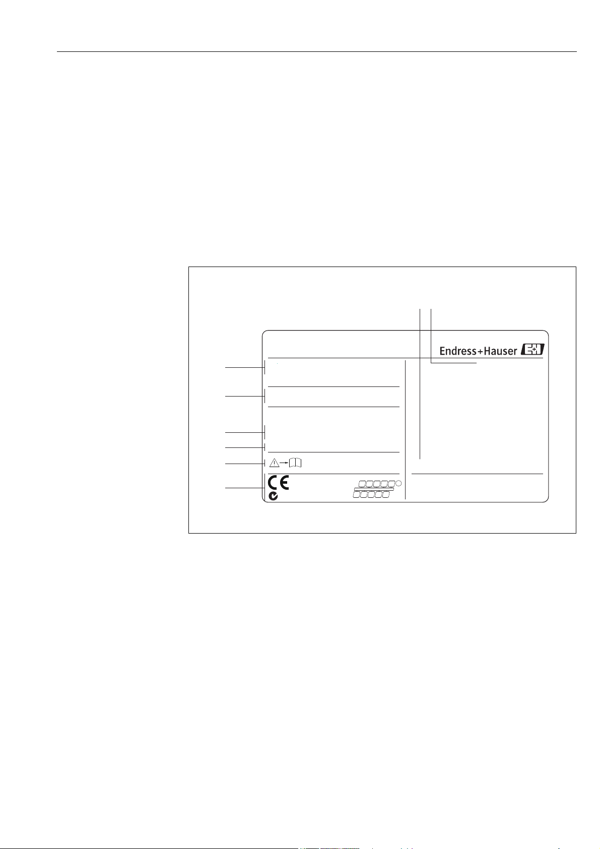
2.1.1 Nameplate of the transmitter
a0005463
Fig. 1: Nameplate specifications for the "t-mass 65" transmitter (example)
1 Order code, serial number: See the specifications on the order confirmation for the meanings of the individual
letters and digits
2 Power supply, frequency, power consumption
3 Available inputs/outputs:
4Reserved for information on special products
5 Please refer to operating instructions / documentation
6 Reserved for certificates, approvals and for additional information on device version
7 Ambient temperature range
8 Degree of protection
Endress+Hauser 7
Page 8
Identification Proline t-mass 65 PROFIBUS DP/PA
1
2
4
5
6
7
9
11
10
3
Proline t-mass F
ABCDEFGHIJKLMNOPQRST
TAG-No.:
Ser.No.:
12345678901
Order Code:
IP67 / NEMA/Type 4X
65F50-XXXXXXXXXXXX
P:
T:
Materials:
Seal:
3.1
-0.5...40bar /-7.25...+580psi gauge
EPDM / PEEK
316/316L/1.4404/Alloy C 22- (2.4602)
-40°C...+100°C /-40°F...+212°F
-20°C(-4°F) <Tamb<+60°C(+140°F)
i
DN50 DIN/EN PN40
N12895
8
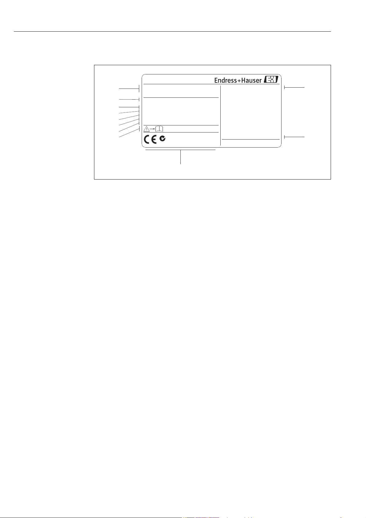
2.1.2 Nameplate of the sensor
a0005512
Fig. 2: Nameplate specifications for the "t-mass F" sensor (example)
1 Order code, serial number: See the specifications on the order confirmation for the meanings of the individual
letters and digits
2 Nominal diameter device
3 Pressure range
4 Temperature range
5 Material of measuring tubes
6 Seal material
7Reserved for information on special products
8 Please refer to operating instructions / documentation
9 Ambient temperature range
10 Degree of protection
11 Reserved for additional information on device version (approvals, certificates)
8 Endress+Hauser
Page 9
Proline t-mass 65 PROFIBUS DP/PA Identification
2
3
1
4
5
6
7
8
9
10
Device SW:
01.Dec 2009
XXXXXXXXXXXXXXXXXX
Drivers:
Communication:
Date:
SW-versionEx-works
See Operating manual
Betriebsanleitung beachten
Observer Manuel d'Instruction
N / LPE
L1 / L+
1 2
319475-0011
20(+)/21(-)
22(+)/23(-)
24(+)/25(-)
26(+)/27(-)
NC:
NO:
P:
A:
Tension d'alimentation
Versorgung /
Supply /
12345678912
Ser. No.:
normally open contact
normally closed contact
passive
active
Update 2
PROFIBUS DP (Profile 3.0)
XX.XX.XX
27 = A (RxD/TxD-N)
26 = B (RxD/TxD-P)
Supply Ext. Termination
25 = DGND
24 = +5V
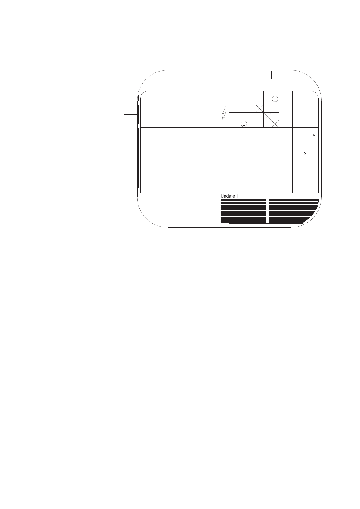
2.1.3 Nameplate for connections
A005464
Fig. 3: Nameplate specifications for transmitter connections (example)
1 Serial number
2 Possible configuration of current output
3 Possible configuration of relay contacts
4 Terminal assignment, cable for power supply: 85 to 260 V AC, 20 to 55 V AC, 16 to 62 V DC
Terminal No. 1: L1 for AC, L+ for DC
Terminal No. 2: N for AC, L– for DC
5 Signals present at inputs and outputs, possible configuration and terminal assignment (20 to 27),
see also "Electrical values of inputs/outputs", ä 107
6 Version of device software currently installed
7 Installed communication type, e.g.: HART, PROFIBUS DP, etc.
8 Information on current communication software (Device Revision and Device Description),
e.g.: Dev. 01 / DD 01 for HART
9 Date of manufacture
10 Current updates to data specified in points 6 to 9
Endress+Hauser 9
Page 10

Identification Proline t-mass 65 PROFIBUS DP/PA
2.2 Certificates and approvals
The devices are designed in accordance with good engineering practice to meet state-of-the-art
safety requirements, have been tested, and left the factory in a condition in which they are safe to
operate. The devices comply with the applicable standards and regulations in accordance with
EN 61010-1 "Protection Measures for Electrical Equipment for Measurement, Control, Regulation
and Laboratory Procedures" and with the EMC requirements of IEC/EN 61326.
The measuring system described in these Operating Instructions thus complies with the statutory
requirements of the EC Directives. Endress+Hauser confirms successful testing of the device by
affixing to it the CE mark.
The measuring system meets the EMC requirements of the Australian Communications and Media
Authority (ACMA).
The flow measuring system has successfully passed all the test procedures carried out and is certified
and registered by the PNO (PROFIBUS User Organization).
The device thus meets all the requirements of the following specifications:
• Certified to PROFIBUS Specification, Profile Version 3.0
Device certification number: available on request
• The device can also be operated with certified devices of other manufacturers (interoperability)
2.3 Registered trademarks
KALREZ® and VITON
Registered trademarks of E.I. Du Pont de Nemours & Co., Wilmington, USA
®
PROFIBUS
Registered trademark of the PROFIBUS User Organization, Karlsruhe, Germany
HistoROM™, S-DAT
Registered or registration-pending trademarks of Endress+Hauser Flowtec AG, Reinach, CH
®
®
, T-DAT™, F-CHIP®, FieldCare®, Fieldcheck®, Applicator®, t-mass
®
10 Endress+Hauser
Page 11
Proline t-mass 65 PROFIBUS DP/PA Installation
3 Installation
3.1 Incoming acceptance, transport and storage
3.1.1 Incoming acceptance
On receipt of the goods, check the following points:
• Check the packaging and the contents for damage.
• Check the shipment, make sure nothing is missing and that the scope of supply matches your
order.
3.1.2 Transport
The following instructions apply to unpacking and to transporting the device to its final location:
• Transport the devices in the containers in which they are delivered.
• The covers or caps fitted to the process connections prevent mechanical damage to the
transducers during transportation and storage. Consequently, do not remove these covers or caps
until immediately before installation.
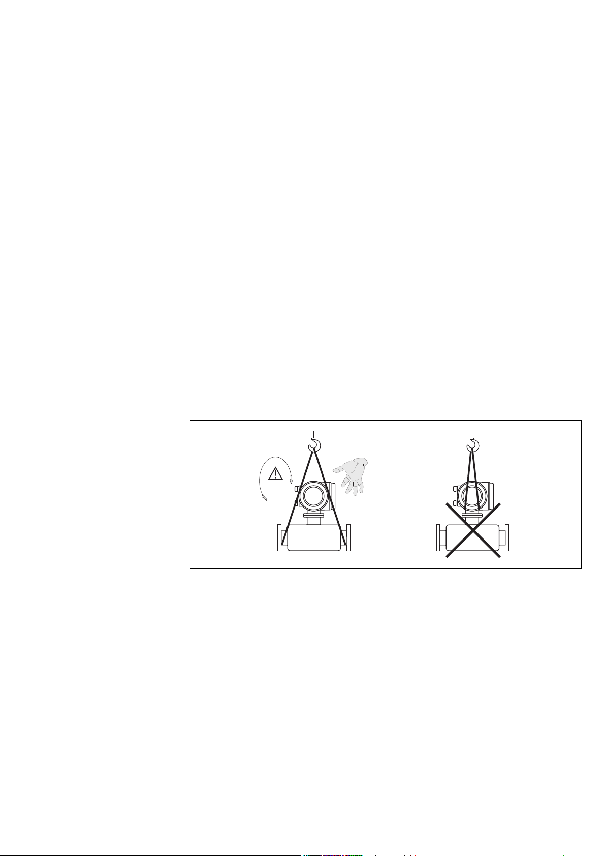
• Do not lift measuring devices of nominal diameters > DN 40 (> 1½") by the transmitter housing
or the connection housing in the case of the remote version ( å 4). Use webbing slings slung
round the two process connections. Do not use chains, as they could damage the housing.
#
Warning!
Risk of injury if the measuring device slips. The center of gravity of the assembled measuring device
might be higher than the points around which the slings are slung.
At all times, therefore, make sure that the device does not unexpectedly turn around its axis or slip.
a0004294
Fig. 4: Instructions for transporting sensors with > DN 40 (> 1½")
3.1.3 Storage
Note the following points:
• Pack the measuring device in such a way as to protect it reliably against impact for storage (and
transportation). The original packaging provides optimum protection.
• The permissible storage temperature is –40 to +80 °C (–40 °F to +176 °F).
Preferably +20 °C (+68 °F).
• Do not remove the protective covers or caps on the process connections until you are ready to
install the device.
• The measuring device must be protected against direct sunlight during storage in order to avoid
unacceptably high surface temperatures.
• Devices delivered with special sealing or bagging for oxygen service must remain sealed or bagged
until ready for installation.
Endress+Hauser 11
Page 12

Installation Proline t-mass 65 PROFIBUS DP/PA
3.2 Installation conditions
Note the following points:
• The thermal dispersion principle is very sensitive to disturbed flow conditions.
• Observe the recommended inlet and outlet requirements.
• Good engineering practice is necessary for the associated pipe work and installation.
• Ensure correct alignment and orientation of the sensor.
• Take measures to reduce or avoid condensation (e.g. install a condensation trap, thermal
insulation, etc.).
• The maximum permitted ambient temperatures and the medium temperature range ( ä 111)
must be observed.
• Install the transmitter in a shaded location or use a protective sun shield.
• For mechanical reasons, and in order to protect the pipe, it is advisable to support heavy sensors.
3.2.1 Dimensions
The dimensions and installation lengths of the sensor and transmitter can be found in the "Technical
Information" for the device in question. This document can be downloaded as a PDF file from
www.endress.com. A list of the "Technical Information" documents available is provided in the
"Documentation" section on ä 116.
3.2.2 System pressure and pulsating flow
Reciprocating pumps and some compressor systems can create strong changes in process pressure
that can induce spurious internal flow patterns and therefore cause additional measurement error.
These pressure pulses must be reduced by the appropriate measures:
• Use of expansion tanks
• Use of inlet expanders
• Relocate the flowmeter further downstream
In compressed air systems, it is recommended to mount the flowmeter after the filter, dryer and
buffer devices to avoid pulsations and oil/dirt contamination. Do not mount the flowmeter directly
after the compressor outlet.
12 Endress+Hauser
Page 13

Proline t-mass 65 PROFIBUS DP/PA Installation
Ã
✘
✘
✘
3.2.3 Pipework requirements
Good engineering practice should be followed at all times:
• Correct preparation, welding and finishing techniques
• Correctly sized gaskets
• Correctly aligned flanges and gaskets
• Connecting pipe work should match the internal diameter of the flowmeter.
Maximum pipe diameter mismatch should not exceed:
– 1 mm (0.04 inch) for diameters < DN 200 (8")
– 3 mm (0.12 inch) for diameters DN 200 (8")
For further information please refer to ISO 14511.
a0005103
Correctly aligned flanges and gaskets
a0005104 a0005105 a0005106
Pipe diameter one is not equal pipe
diameter two
Caution!
"
New installations should be free of metallic and abrasive particles to prevent damage to the sensing
elements on start-up.
Incorrectly sized gaskets Incorrectly aligned flanges and gaskets
Endress+Hauser 13
Page 14
Installation Proline t-mass 65 PROFIBUS DP/PA
3.2.4 Orientation
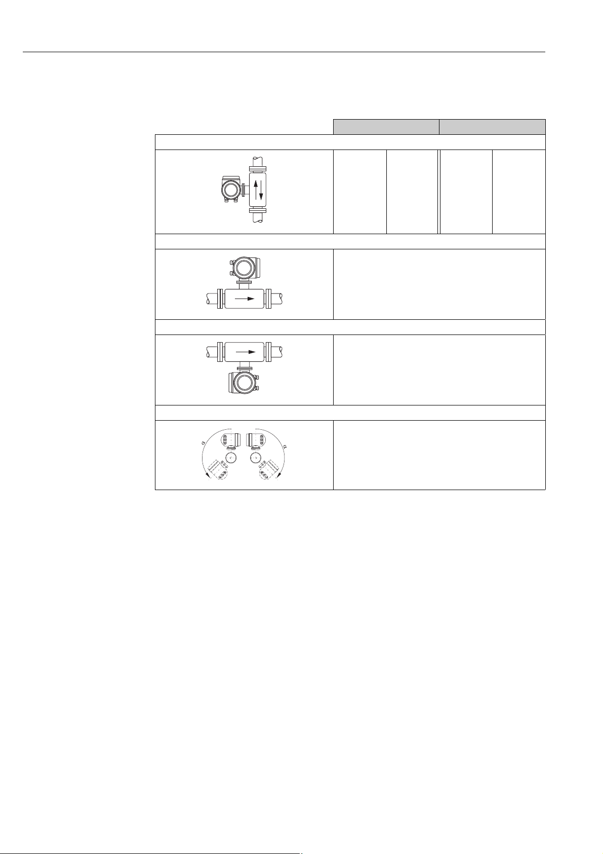
Make sure that the direction arrow on the sensor matches the direction of gas flow through the pipe.
Flanged sensor Insertion sensor
Vertical orientation
compact
remote
compact
remote
ÃÃ
m
A0013785
ÃÃ
m
Ã
m, n
ÃÃ
m
Horizontal orientation, transmitter head up
compact/remote
ÃÃ
A0013786
n
Horizontal orientation, transmitter head down
compact/remote
Ã
A0013787
o
Inclined orientation, transmitter head down
compact/remote
Ã
A0009897
p
ÃÃ = Recommended orientation
à = Orientation recommended in certain situations
m In the case of saturated or unclean gases, upward flow in a vertical pipe section is preferred to minimize
condensation/contamination.
n Not recommended if the vibrations are too high or if the installation is unstable.
o Only suitable for clean/dry gases. Do not mount the sensor from the bottom, on horizontal pipes, if build-up or
condensate are likely to be present. Mount the sensor in a position as indicated below
p If the gas is very damp or saturated with water (e. g. Bio Gas), mount in inclined orientation (max. 135°).
14 Endress+Hauser
Page 15
Proline t-mass 65 PROFIBUS DP/PA Installation
15xDN 2xDN
15xDN
2xDN
15xDN
2xDN
20xDN
2xDN
35xDN
2xDN
50xDN
2xDN
20xDN 5xDN
20xDN 5xDN
20xDN 5xDN
25xDN 5xDN
40xDN 5xDN
50xDN 5xDN
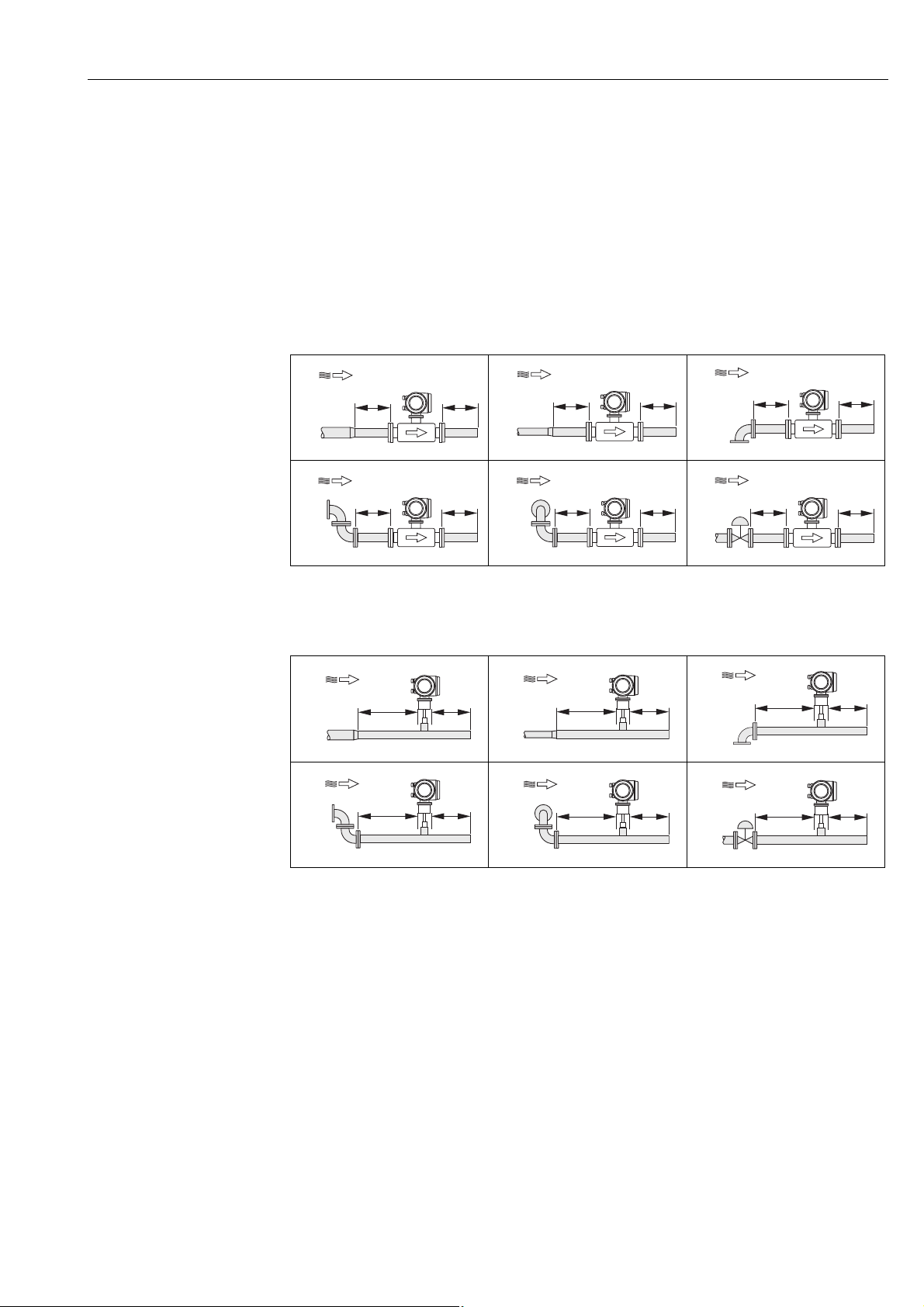
3.2.5 Inlet and outlet runs
The thermal dispersion principle is sensitive to disturbed flow conditions.
As a general rule, the thermal flowmeter should always be installed as far away as possible from any
flow disturbances. For further information please refer to ISO 14511.
!
Note!
• Where two or more flow disturbances are located upstream of the meter, the longest indicated
inlet length should prevail. For example if a control valve and a bend are mounted upstream of
the flowmeter, the recommended inlet length should be according to the control valve (50 × DN).
• For very light gases such as Helium and Hydrogen all upstream distances should be doubled.
The minimum recommendations for inlet and outlet runs (without flow conditioner) are:
Flanged sensor
1
2
3
a0007523
4
1 = Reduction, 2 = Expansion, 3 = 90° elbow or T-piece, 4 = 2 × 90° elbow, 5 = 2 × 90° elbow (3-dimensional),
6 = Control valve
5
a0007526
a0007524
6
a0007527
Insertion sensor
1
4
1 = Reduction, 2 = Expansion, 3 = 90° elbow or T-piece, 4 = 2 × 90° elbow, 5 = 2 × 90° elbow (3-dimensional),
6 = Control valve or pressure regulator
a0007529
a0007532
2
5
3
a0007530
6
a0007564
a0007525
a0007528
a0007531
a0007534
Endress+Hauser 15
!
Note!
A specially designed perforated plate flow conditioner can be installed if it is not possible to observe
the inlet runs required ( ä 16).
Page 16
Installation Proline t-mass 65 PROFIBUS DP/PA
PT
2...5xDN
2 × DN5 × DN
8 × DN 5 × DN
5 × DN
2
1
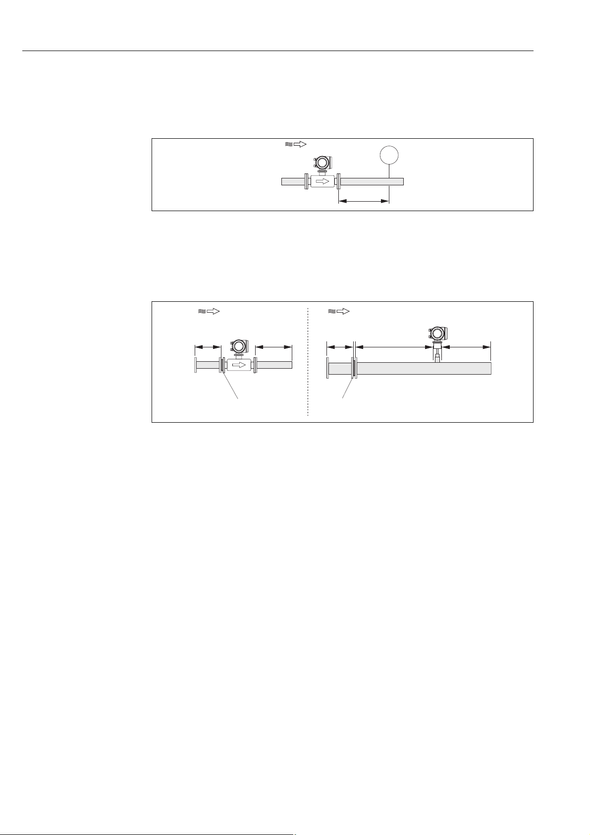
Outlet runs with pressure measuring points
The pressure measuring point should be installed downstream of the measuring device, so that there
is no potential influence of the pressure transmitter process connection on the flow entering the
measuring point.
a0005114
Fig. 5: Installing a pressure measuring point (PT = pressure transmitter)
Perforated plate flow conditioner
It is recommended to install a perforated plate flow conditioner if the recommended inlet runs are
not available. See accessories ä 87.
a0005115
Fig. 6: The figure above illustrates the minimum recommended inlet and outlet runs expressed in multiples of the pipe
1 = Flow conditioner with the flanged sensor, 2 = Flow conditioner with the insertion sensor
diameter using a flow conditioner.
Flow conditioner for use with insertion sensors
The well known "Mitsubishi" design is recommended for this application DN 80 mm (3") to
DN 300 mm (12"). The flow conditioner must be installed at a distance of 8 × DN upstream of the
sensor. A further 5 pipe diameters inlet run is required upstream of the actual conditioner itself.
16 Endress+Hauser
Page 17
Proline t-mass 65 PROFIBUS DP/PA Installation
1
2
2
3
4
✘
Ã
Ã
1
1
1
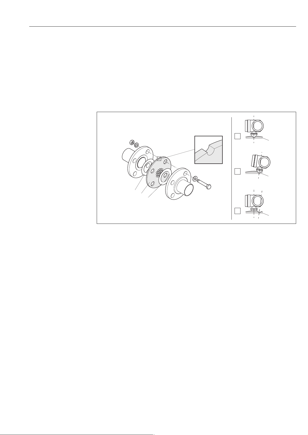
Flow conditoner for use with flanged sensors ä 87
This is a special Endress+Hauser version designed specially for use with the t-mass F sensor (sizes
DN 25 to 100 / 1" to 4"). The mounting hole patterns and sizing are of a multi-variant design which
means that one plate will fit different flange pressure classes e.g. Cl. 150 and Cl. 300.
The flow conditioner and gaskets are fitted between two pipe flange and the flow meter
flange å 7 .
Use only bolts which match to tehflange bolt hole and this will ensure that the correct positioning
of the plate can be found. The alignment notch must also be pointing in the same plane as the
transmitter.
Incorrect installation of the flow conditioner will have a small effect on the measurement accuracy.
!
a0005116
Fig. 7: Flow conditioner mounting arrangement (example)
1 = perforated plate flow conditioner, 2 = aeal/gasket, 3 = alignment notch, 4 = alignment in the same plane as the
transmitter
Note!
• For optimum performance, it is advised that the t-mass F sensor and flow conditioner are ordered
at the same time such that they are calibrated together. To retrospectively fit a flow conditioner
will have a small effect on the measurement performance.
• The use of other types of flow conditioners, other than the Endress+Hauser flow conditioner, with
the t-mass F sensor will have an impact on the measurement performance due to the effects of
flow profile and pressure drop.
• Bolts, nuts, seals, etc. are not included in the scope of supply and must be supplied by the
customer.
Endress+Hauser 17
Page 18
Installation Proline t-mass 65 PROFIBUS DP/PA
aa
bb
3.2.6 Heating
Some applications require suitable measures to avoid heat loss (condensation). Heating can be
electric, e. g. with heated elements, or by means of hot water, steam pipes or insulation.
Caution!
"
Risk of electronics overheating! Consequently, make sure that the adapter between sensor and
transmitter and the connection housing of the remote version always remain free of insulating
material.
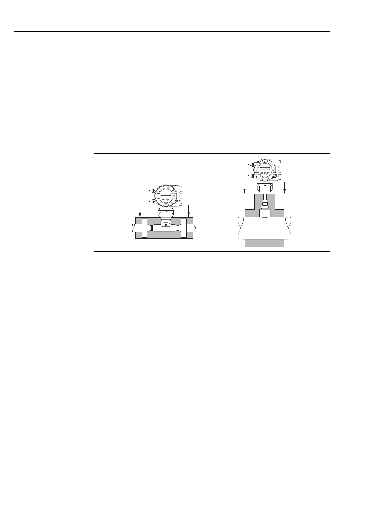
3.2.7 Thermal insulation
When the gas is very damp or saturated with water (e. g. bio gas), the piping and flowmeter body
should be insulated to prevent water droplets condensing on the measuring sensor.
Fig. 8: Maximum thermal insulation for t-mass 65F and 65I
a Maximum insulation height for the flanged sensor
b Maximum insulation height for the insertion sensor
3.2.8 Vibrations
Caution!
"
Excessive vibration can result in mechanical damage to the measuring device and its mounting.
Observe the vibration spezification in the technical data section ä 110
a0005122
18 Endress+Hauser
Page 19
Proline t-mass 65 PROFIBUS DP/PA Installation
90°
90°
3.3 Installation instructions
3.3.1 Mounting the insertion sensor
The sensor can be mounted into a welding socket or a retractable mounting set. If a retractable
mounting set is being used, then refer to the supplementary documentation delivered with the
mounting set.
Mounting the welding socket
This instruction describes mounting of the Endress+Hauser welding socket. If an existing or
customer-specific mounting set is being used, then go to the next section "Insertion depth
calculation and adjustment".
!
"
#
Note!
• Take the orientation and inlet and outlet runs into account before mounting the welding
socket ä 14 ff.
• The welding socket is made of stainless steel 1.4404 (316/316L). Use appropriate welding
technique.
Caution!
When mounting the fitting to a thin wall duct, use a suitable support bracket for the sensor and weld
the welding socket to a base plate to spread the load. Otherwise, the mounting may be unstable and
the duct wall can be damaged.
Warning!
• These instructions are only applicable to installation in an un-pressurized line, without gas present
and at safe temperatures.
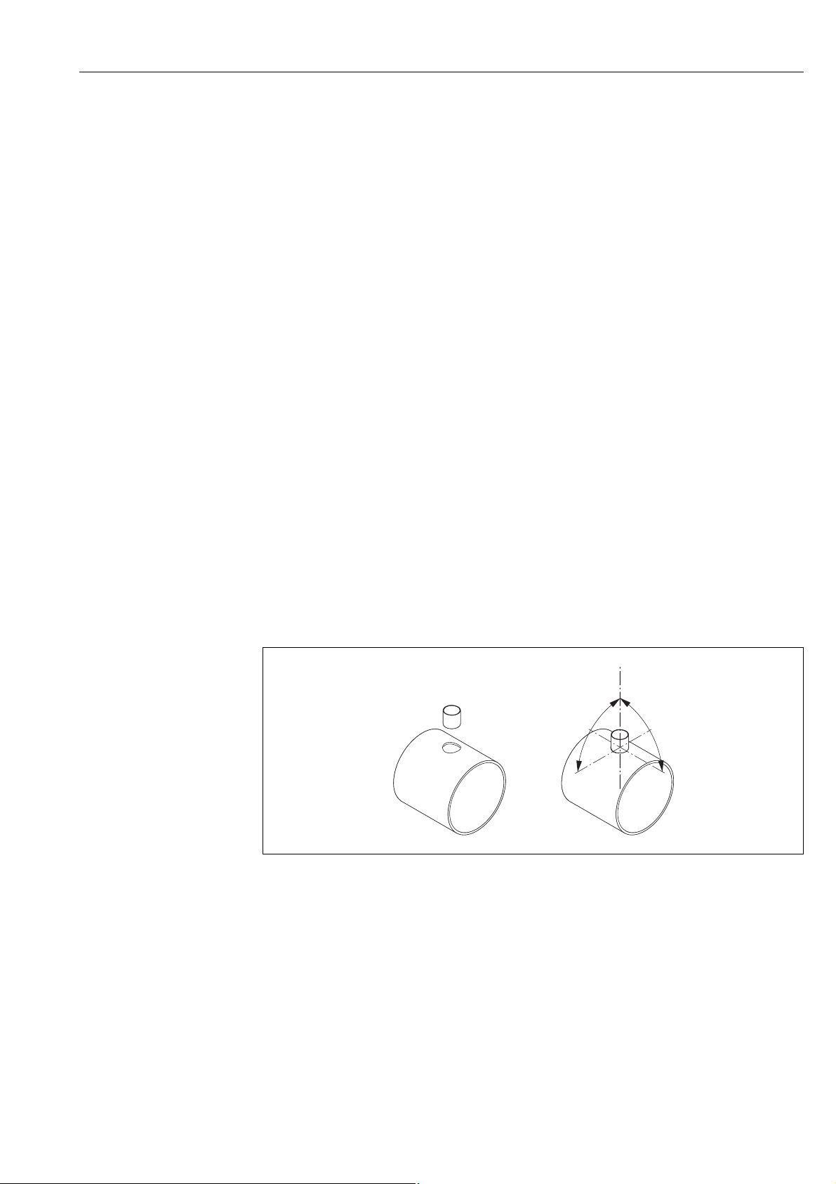
1. Drill or cut hole of Ø 31.0 mm ± 0.5 mm (1.22" ± 0.019") in the pipe.
2. Deburr the hole.
3. Fit the edge of the welding socket into hole, align it vertically and weld it on å 9.
A0010098
Fig. 9: Positioning the welding socket on the pipe (or duct)
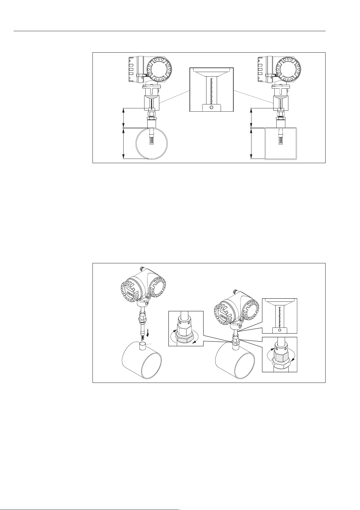
Insertion depth calculation and adjustment
To obtain the best measurement results, it is important that the sensor is inserted at the right
insertion depth in the pipe/duct. A millimeter and inch scale is provided along the entire length of
the sensor tube. This makes it possible to align the sensor at the right depth.
4. Calculate the insertion depth:
– with the help of the Quick Setup "Sensor" ä 51 or
– using the following dimensions and formulae
Endress+Hauser 19
Page 20
Installation Proline t-mass 65 PROFIBUS DP/PA
A B
C
A B
C
230
220
210
200
190
180
9
8
7
230
220
210
200
190
180
9
8
7
230
220
210
200
190
180
9
8
7
1
3
4
2
230
220
210
200
190
180
9
8
7
A0005118
Fig. 10: Dimensions needed to calculate the insertion depth
A Pipes: internal diameter
Ducts: internal dimension
B Wall thickness
C Dimension from pipe/duct to the compression fitting
!
Note!
For detailed remarks on calculation refer to Technical Information TI069D.
• Calculated insertion depth (SI units)= 0.3 · A + B + C + 2 mm
• Calculated insertion depth (US units) = 0.3 · A + B + C + 0.079 inch
Note down the calculated value.
A0010001
Fig. 11: Aligning the sensor to the calculated insertion depth
5. Insert the sensor into the socket (1) and tighten the lower nut of compression fitting (2) first
by hand and then tighten it 1¼ revolutions using a wrench (42 mm).
6. Tighten the upper nut of compression fitting (3) such that the sensor can still be adjusted.
Caution!
"
– NPT thread: use a thread sealing tape or paste
– G 1 A thread: the sealing ring supplied must be installed
7. Read off the calculated insertion depth from the scale and adjust the sensor so that the value
20 Endress+Hauser
aligns with the upper end of the compression fitting (4).
Page 21
Proline t-mass 65 PROFIBUS DP/PA Installation
90°±7°
90°±3°
B
A
1
2
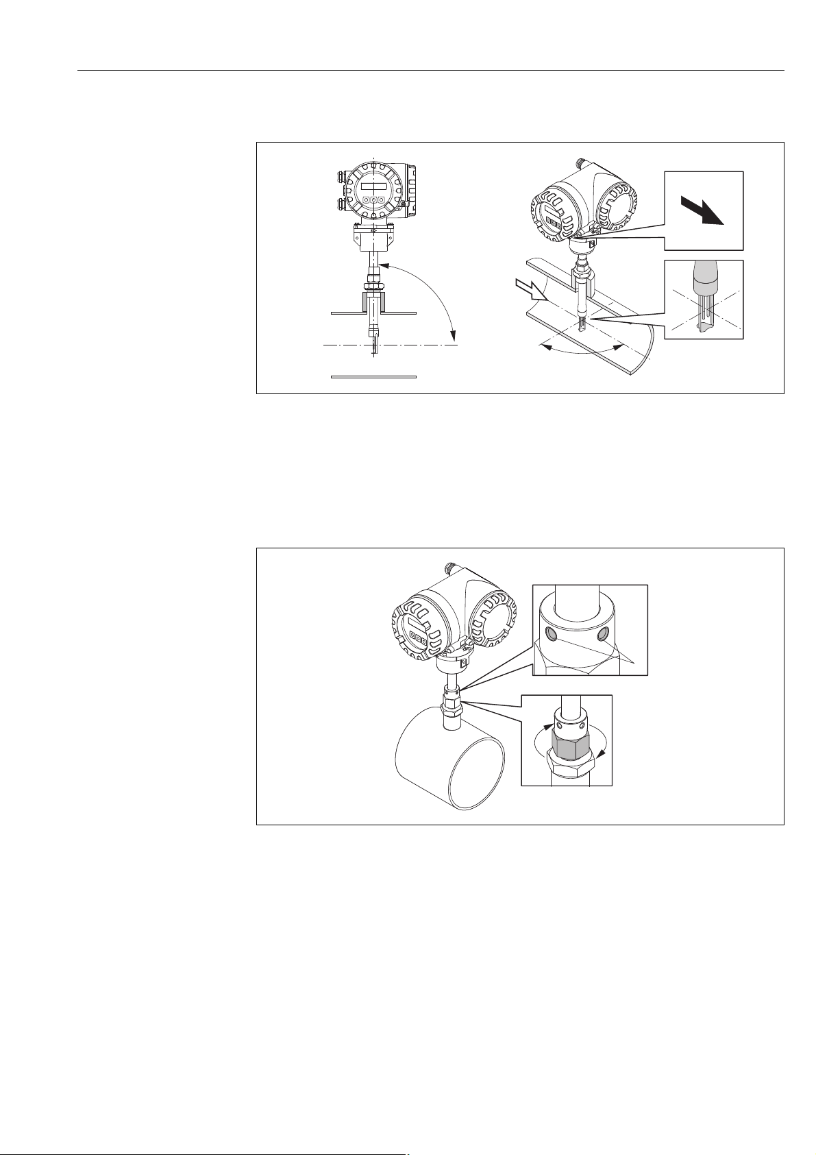
Aligning the sensor with the flow direction
A0005117
Fig. 12: Aligning the sensor with the flow direction
!
8. Check and ensure that the sensor is aligned vertically at a 90° angle on the pipe/duct.
Turn the sensor so that the arrow marking matches the direction of flow.
Note!
To ensure optimum exposure of the measuring transducers to the flowing gas stream, the sensor
must not be rotated more than 7 degrees from this alignment.
A0010114
Fig. 13: Securing the position of the sensor
9. Tighten the compression fitting (1) by hand to secure the position of the sensor. Then, using
an open-ended wrench, tighten another 1¼ revolutions in a clockwise direction.
10. Fix the two securing screws (2) (Allen key 3 mm; 1/8").
Warning!
#
Observe torque: 4 Nm (2.95 lbf ft)
11. Check that the sensor and transmitter do not turn.
12. Check the measuring point for leaks at the maximum operating pressure.
Endress+Hauser 21
Page 22
Installation Proline t-mass 65 PROFIBUS DP/PA
1
2
3
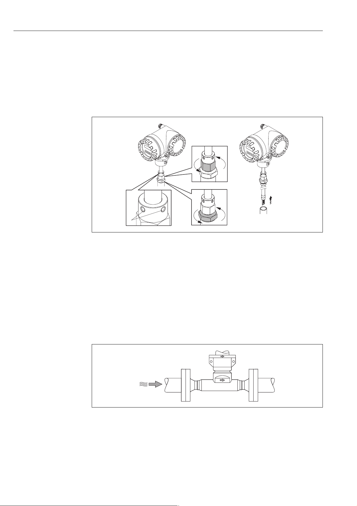
3.3.2 Removing the insertion sensor
#
Warning!
• Do not remove the measuring device when it is pressurized! Stop the gas flow and unpressurize
the process pipe.
• In the case of toxic, explosive or flammable gases, the pipe in which the measuring device is
installed must be purged with an inert gas to remove all traces of the gas used.
• Make sure that the process cannot be resumed while removal work is in progress.
• Allow the system and device to cool to a safe temperature (i.e. <50 °C, <120 ° F).
A0011016
Fig. 14: Removing the insertion sensor
1. Release the securing screws (1).
2. Release the upper nut of compression fitting using a wrench, turning in a counterclockwise
direction (2).
Caution!
"
In the case of vertical installation, do not drop the measuring device into the pipe.
3. Unscrew the lower nut of compression fitting (3) and remove the sensor.
3.3.3 Mounting the flanged sensor
The arrow on the sensor must match with the actual direction of flow through the pipe.
A0013663
Fig. 15: Mounting in direction of flow
22 Endress+Hauser
Page 23
Proline t-mass 65 PROFIBUS DP/PA Installation
3
5
6
1
2
4
4 x 45°
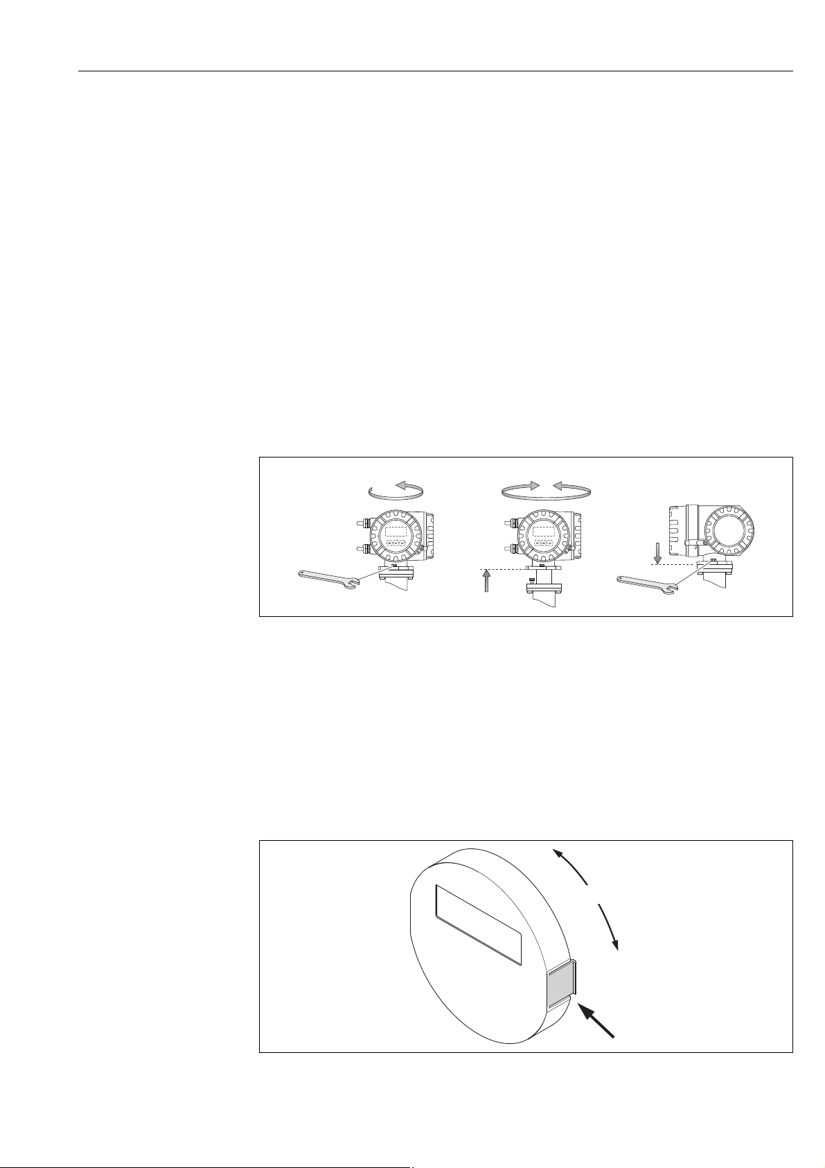
3.3.4 Turning the transmitter housing
Turning the aluminium field housing
#
Warning!
The rotating mechanism for devices for hazardous areas Zone 1 (ATEX/IEC Ex) or Class I Div. 1
(FM/CSA) is different to that described here. The procedure for turning these housings is described
in the Ex-specific documentation ä 116.
1. Loosen the two securing screws.
Caution!
"
Special screw! Do not loosen screw completely or replace with another screw.
Use only original parts from Endress+Hauser.
2. Turn the bayonet catch as far as it will go.
3. Carefully lift the transmitter housing as far as it will go.
4. Turn the transmitter housing to the desired position (max. 2 × 90° in either direction).
5. Lower the housing into position and re-engage the bayonet catch.
6. Retighten the two securing screws.
a0004302
Fig. 16: Turning the transmitter housing (aluminium field housing)
3.3.5 Turning the local display
1. Unscrew cover of the electronics compartment from the transmitter housing.
2. Press the side latches on the display module and remove the module from the electronics
compartment cover plate.
3. Rotate the display to the desired position (4 × 45 ° in both directions), and reset it onto the
electronics compartment cover plate.
4. Screw the cover of the electronics compartment firmly back onto the transmitter housing.
A0003236
Fig. 17: Turning the local display (field housing)
Endress+Hauser 23
Page 24
Installation Proline t-mass 65 PROFIBUS DP/PA
a
b
c
c
90 (3.54)
35 (1.38)
192 (7.56)
81.5(3.2)
mm (inch)
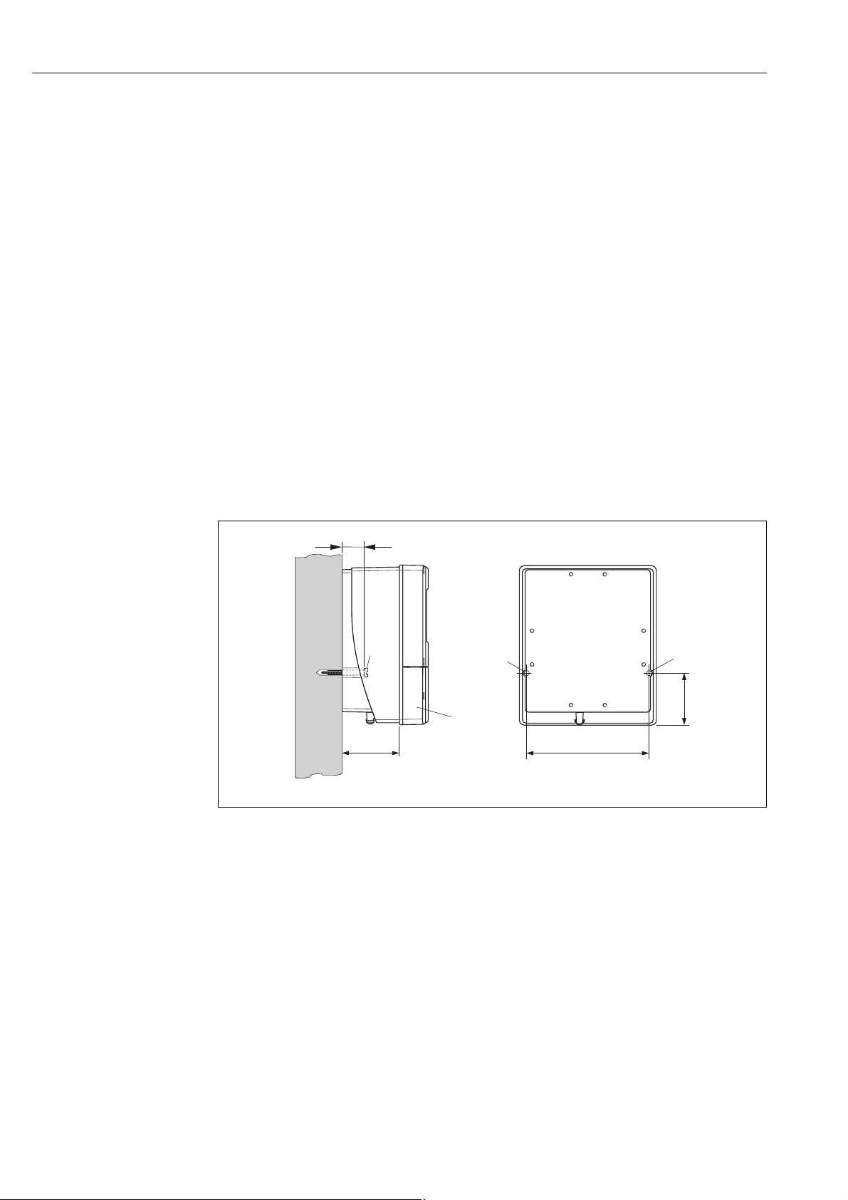
3.3.6 Installing the wall-mount transmitter housing
There are various ways of installing the wall-mount transmitter housing:
• Mounted directly on the wall
• Installation in control panel ä 25 (separate mounting set, accessories ä 87)
•Pipe mounting ä 25 (separate mounting set, accessories ä 87)
Caution!
"
• Make sure that ambient temperature does not go beyond the permissible range of
– 20 °C to +60 °C (–4 °F to +140 °F), optional – 40 °C to +60 °C (–40 °F to +140 °F).
• Install the device in a shaded location. Avoid direct sunlight on the display.
• Always install the wall-mount housing in such a way that the cable entries are pointing down.
Mounted directly on the wall
1. Drill the holes as illustrated in the diagram.
2. Remove the cover of the connection compartment (a).
3. Push the two securing screws (b) through the appropriate bores (c) in the housing.
– Securing screws (M6): max. Ø 6.5 mm (0.25 inch)
– Screw head: max. Ø 10.5 mm (0.4 inch)
4. Secure the transmitter housing to the wall as indicated.
5. Screw the cover of the connection compartment (a) firmly onto the housing.
a0001130-ae
Fig. 18: Mounted directly on the wall
24 Endress+Hauser
Page 25
Proline t-mass 65 PROFIBUS DP/PA Installation
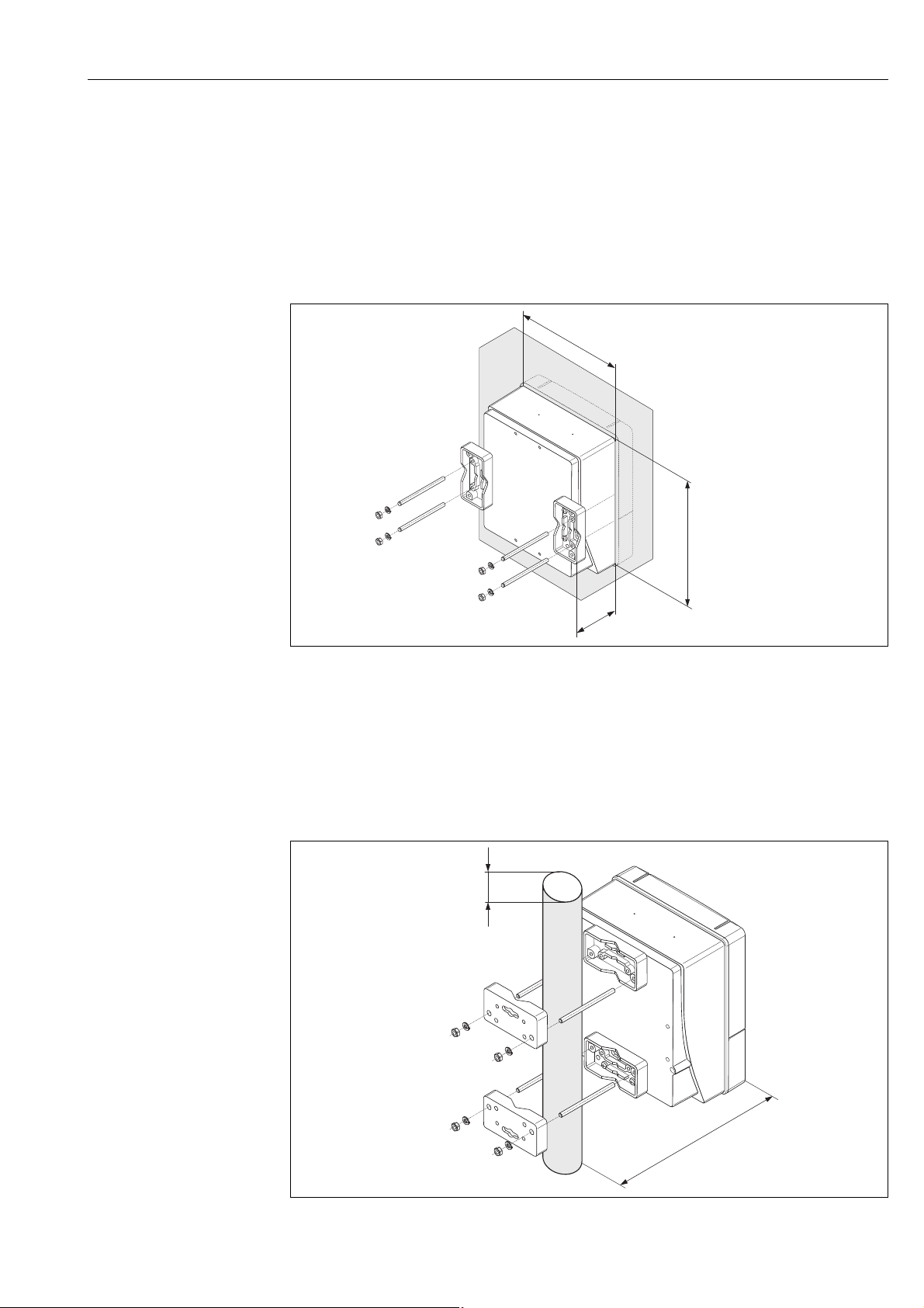
245(9.65)
~110 (~4.33)
210 (8.27)
+0.5 (+0.019)
–0.5(–0.019)
+0.5 (+0.019)
–0.5(–0.019)
mm (inch)
Ø 20…70
(Ø 0.79…2.75)
~~6.1)155 (
mm (inch)
Installation in control panel
1. Prepare the opening in the panel as illustrated in the diagram.
2. Slide the housing into the opening in the panel from the front.
3. Screw the fasteners onto the wall-mount housing.
4. Screw threaded rods into holders and tighten until
the housing is solidly seated on the panel wall. Afterwards, tighten the locking nuts.
Additional support is not necessary.
Fig. 19: Panel installation (wall-mount housing)
Pipe mounting
The assembly should be performed by following the instructions in the diagram.
Caution!
"
If a warm pipe is used for installation, make sure that the housing temperature does not exceed the
max. permitted value of +60 °C (+140 °F).
a0001131
Fig. 20: Pipe mounting (wall-mount housing)
Endress+Hauser 25
a0001132
Page 26
Installation Proline t-mass 65 PROFIBUS DP/PA
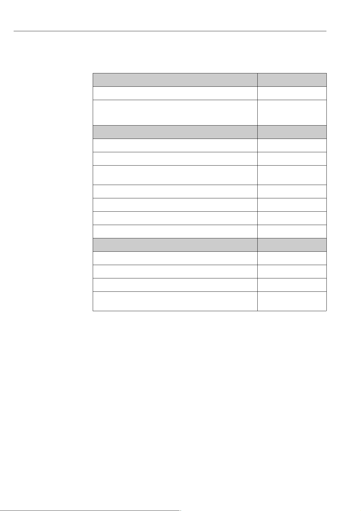
3.4 Post-installation check
Perform the following checks after installing the measuring device in the pipe:
Device condition and specifications Notes
Is the device damaged (visual inspection)? –
Does the device correspond to specifications at the measurement point, including
process temperature and pressure, ambient temperature, measuring range, etc.?
Check the name plate.
Installation Notes
Correct alignment of pipe/gasket/flowmeter body? ä 13
Professional installation (correct pipe internal diameter, correctly sized gaskets)? ä 13
Is the position chosen for the sensor correct, in other words suitable for sensor
type, fluid properties and fluid temperature?
Is there sufficient upstream and downstream pipe sensor? ä 15
Correct installation of flow conditioner (if fitted)? ä 16
Does the arrow on the sensor match the direction of flow through the pipe? ä 14
Correct sensor depth (insertion sensor only)? ä 19
Process environment / process conditions Notes
Is the measuring device protected against moisture and direct sunlight? –
Is the measuring device protected against overheating? ä 18
ä 7
ä 14
Is the measuring device protected against excessive vibration? ä 18, ä 110
Check gas conditions (e. g. purity, dryness, cleanliness) Select suitable orientation
ä 14
26 Endress+Hauser
Page 27
Proline t-mass 65 PROFIBUS DP/PA Wiring
4 Wiring
#
!
Warning!
When connecting Ex-certified devices, see the notes and diagrams in the Ex-specific supplement to
these Operating Instructions. Please do not hesitate to contact your Endress+Hauser representative
if you have any questions.
Note!
The device does not have an internal power isolation switch. Therefore provide an isolation switch
or circuit breaker which can be used to disconnect the power supply to the device.
4.1 Cable specifications
4.1.1 PROFIBUS DP cable specifications
Cable type
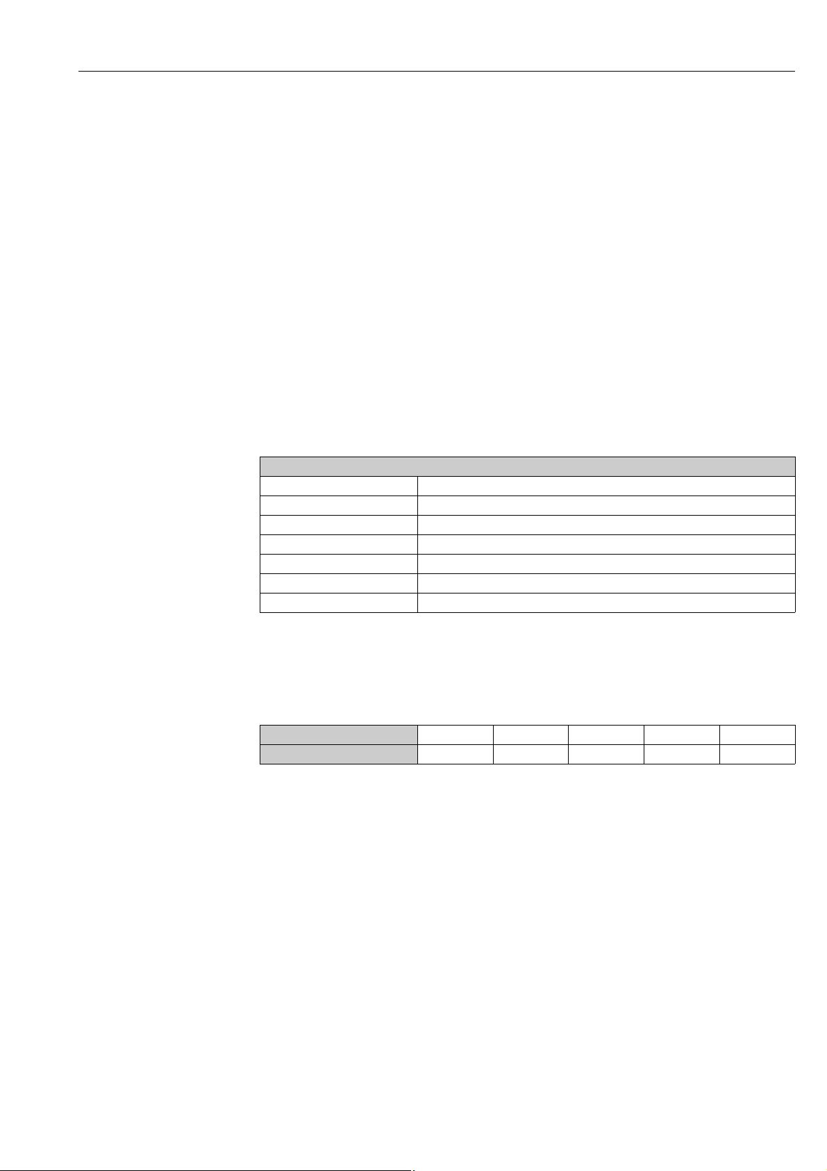
Two versions of the bus line are specified in IEC 61158. Cable type A can be used for all
transmission rates up to 12 Mbit/s.
Cable type A
Characteristic impedance 135 to 165 at a measuring frequency of 3 to 20 MHz
Cable capacitance < 30 pF/m
Core cross-section > 0.34 mm
Cable type Twisted in pairs, 1 × 2, 2 × 2 or 1 × 4 wire
Loop-resistance 110 /km
Signal damping Max. 9 dB over the entire length of the cable section
Shielding Copper braided shielding or braided shielding and foil shielding
, corresponds to AWG 22
Bus structure
Note the following points:
• The maximum line length (segment length) depends on the transmission rate.
For cable type A, the maximum line length (segment length) is as follows:
Transmission rate [kBit/s] 9.6 to 93.75 187.5 500 1500 3000 to 12 000
Line length [m]([inch]) 1200 (4000) 1 000 (3 300) 400 (1300) 200 (650) 100 (330)
• A maximum of 32 users are permitted per segment.
• Each segment is terminated at either end with a terminating resistor.
• The bus length or the number of users can be increased by introducing a repeater.
• The first and last segment can comprise max. 31 devices.
The segments between the repeaters can comprise max. 30 stations.
• The maximum distance between two bus users can be calculated as follows:
(NO_REP + 1) × segment length
Note!
!
NO_REP = maximum number of repeaters that may be switched in series depending on the
repeater in question.
Example
In accordance with manufacturer specifications, 9 repeaters can be switched in series when using
a standard line. The maximum distance between two bus users at a transmission rate of
1.5 MBit/s can be calculated as follows: (9 + 1) × 200 m = 2000 m
Endress+Hauser 27
Page 28

Wiring Proline t-mass 65 PROFIBUS DP/PA
Spurs
Please note the following:
• Length of spurs < 6.6 m (21.7 ft) (at max. 1.5 MBit/s)
• No spurs should be used for transmission rates >1.5 MBit/s. The line between the connector and
the bus driver is described as a spur. Experience has shown that you should proceed with caution
when configuring spurs. For this reason, you cannot presume that the sum of all spurs at
1.5 MBit/s may be 6.6 m (21.7 ft). This is affected greatly by the arrangement of the field devices.
Therefore, we recommend you do not use any spurs, if possible, at transmission rates
>1.5 MBit/s.
• If you cannot avoid using spurs, then they may not include any bus terminators.
Bus termination
It is important to terminate the RS485 line correctly at the start and end of the bus segment since
impedance mismatch results in reflections on the line which can cause faulty communication
ä 45.
Further information
General information and further notes regarding the wiring can be found in BA034S/04:
"Guidelines for planning and commissioning, PROFIBUS DP/PA, field communication".
4.1.2 Shielding and grounding
When planning the shielding and grounding for a fieldbus system, there are three important points
to consider:
• Electromagnetic compatibility (EMC)
• Explosion protection
• Safety of the personnel
To ensure the optimum electromagnetic compatibility of systems, it is important that the system
components and above all the cables, which connect the components, are shielded and that no
portion of the system is unshielded. Ideally, the cable shields are connected to the normally metal
housings of the connected field devices. Since these are generally connected to the protective
ground, the shield of the bus cable is grounded many times. Ensure that the stripped and twisted
lengths of cable shield to the ground terminal are as short as possible.
This approach, which provides the best electromagnetic compatibility and personnel safety, can be
used without restriction in systems with good potential matching.
In the case of systems without potential matching, a power supply frequency (50 Hz) equalizing
current can flow between two grounding points which, in unfavorable cases, e.g. when it exceeds
the permissible shield current, may destroy the cable.
To suppress the low frequency equalizing currents, it is therefore recommended - in the case of
systems without potential equalization - to connect the cable shield directly to the building ground
(or protective ground) at one end only and to use capacitive coupling to connect all other grounding
points.
Caution!
"
The statutory EMC requirements are only met if the cable shield is grounded at both ends!
28 Endress+Hauser
Page 29
Proline t-mass 65 PROFIBUS DP/PA Wiring
N
i
c
h
t
u
n
t
e
r
S
p
a
n
n
u
n
g
ö
f
f
n
e
n
K
e
e
p
c
o
v
e
r
t
i
g
h
t
w
h
i
l
e
c
i
r
c
u
i
t
s
a
r
e
a
l
i
v
e
N
e
p
a
s
o
u
v
r
i
r
l
’
a
p
p
a
r
e
i
l
s
o
u
s
t
e
n
s
i
o
n
K
e
e
p
c
o
v
e
r
t
i
g
h
t
w
h
i
l
e
c
i
r
c
u
i
t
s
a
r
e
a
l
i
v
e
AB
C
D
41 42 43 44
GND
6…
10V
COMMS
+
-
+
-
GND
COMMS
--
++
41 42 43 44
6…
10V
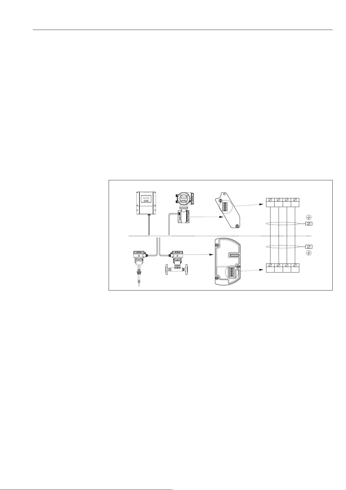
4.2 Connecting the remote version
4.2.1 Connecting connecting cable for sensor/transmitter
#
Warning!
• After removing the electronics cover, there is a risk of electric shock as shock protection is
removed! Switch off the measuring device before removing internal covers.
• Risk of electric shock. Connect the protective earth to the ground terminal on the housing before
the power supply is applied.
1. Remove the connection compartment cover by loosening the fixing screws on the transmitter
and sensor housing.
2. Feed the connecting cable through the appropriate cable entry.
3. Establish the connections between sensor and transmitter in accordance with the wiring
diagram: ( å 21 or see wiring diagram in screw cap; wire cross-section: max. 2.5 mm² /
AWG 13).
4. Screw the connection compartment cover back onto the sensor and transmitter housing.
!
a0005123
Fig. 21: Connecting the remote version
A Wallmount housing; Non-hazardous area and zone 2 (ATEX II3G, FM/CSA) see separate "Ex documentation"
B Field housing; Zone 1 (ATEX II2GD, IECEx, FM/CSA) see separate "Ex documentation"
C Remote sensor insertion
D Remote sensor flanged
Wire colors (when supplied by Endress+Hauser):
Terminal no. 41 = white; 42 = brown; 43 = green; 44 = yellow
4.2.2 Cable specification, connecting cable
The specifications of the cable connecting the transmitter and the sensor of the remote version are
as follows:
• 2 × 2 × 0.5 mm² (AWG 20) PVC cable with common shield (2 twisted pairs)
• Conductor resistance: 40 /km ( 131.2 /1000 ft)
• Operating voltage: 250 V
• Temperature range: –40 to +105 °C (–40 to +221 °F)
• Overall nominal diameter: 8.5 mm (0.335")
• Maximum cable length: 100 m (328 feet)
Note!
• The cable must be installed securely to prevent movement
• The cable should be of sufficient diameter to provide adequate sealing of the cable gland
ä 109.
Endress+Hauser 29
Page 30
Wiring Proline t-mass 65 PROFIBUS DP/PA
4.3 Connecting the measuring unit
!
Note!
The electrical characteristic quantities are listed in the "Technical data" section.
4.3.1 Terminal assignment
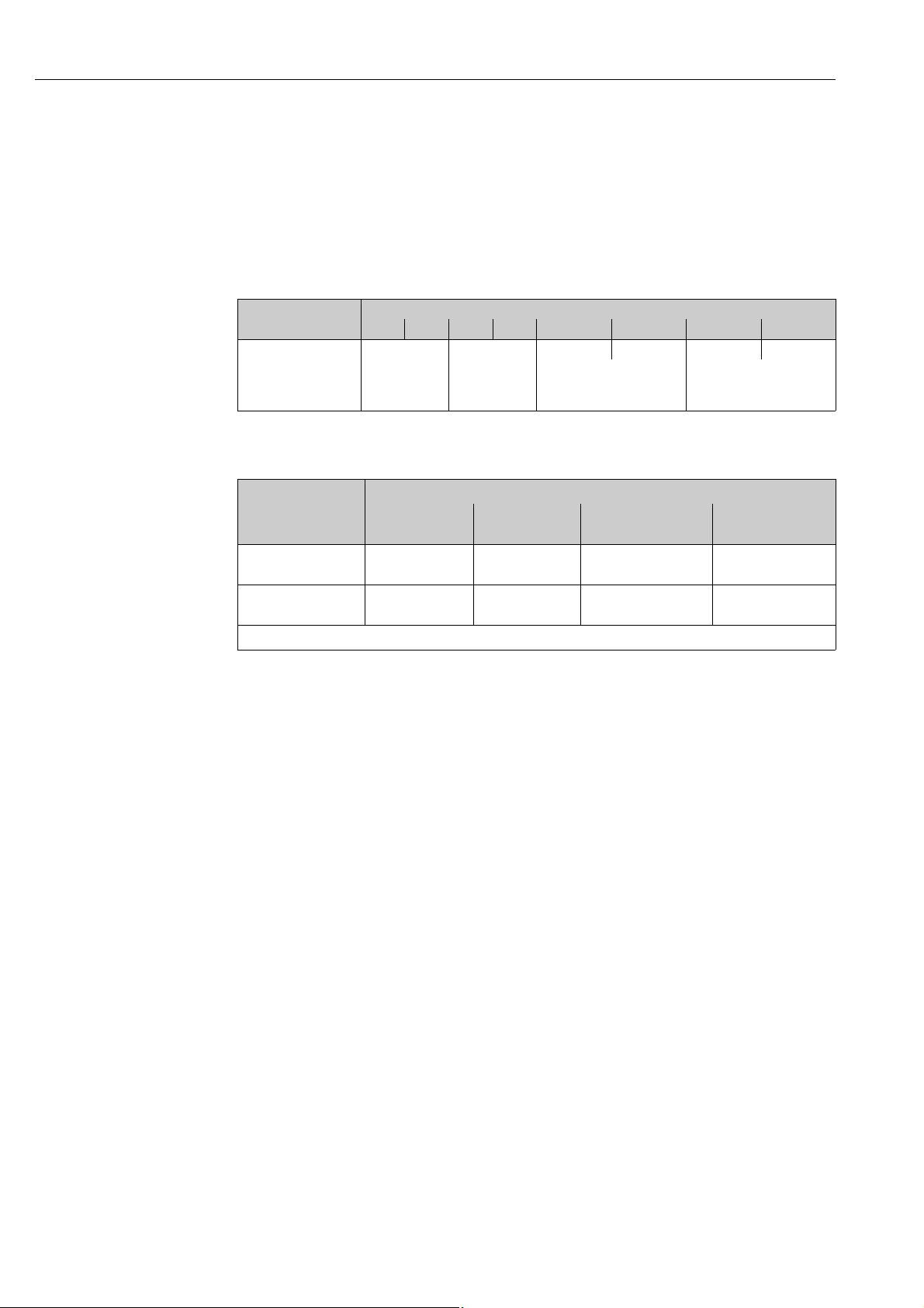
PROFIBUS DP
Terminal No. (inputs/outputs)
Order version
65F**-***********J
65I-*************J
PROFIBUS PA
PROFIBUS PA
Order version 20 (+) / 21 (–) 22 (+) / 23 (–) 24 (+) / 25 (–) 26 = PA +
65F**-***********F
65I-*************F
65F**-***********H
65I-*************H
With integrated reverse polarity protection
20 (+) 21 (–) 22 (+) 23 (–) 24 (+) 25 (–) 26 (+) 27 (–)
+5 V DGND B A
––
-- -
-- -
power supply for external
termination
(optional)
Terminal No. (inputs/outputs)
PROFIBUS DP
A = RxD/TxD-N
B = RxD/TxD-P
27 = PA –
PROFIBUS PA, Ex i
PROFIBUS PA
1)
1)
#
4.3.2 Transmitter connection
Warning!
• Risk of electric shock. Switch off the power supply before opening the device. Do not install or
he device while it is connected to the power supply. Failure to comply with this precaution
wire t
can result in irreparable damage to the electronics.
• Risk of electric shock. Connect the protective earth
to the ground
the power supply is applied unless special protection measures have been taken
(e.g. galvanically isolated power supply SELV or PELV).
• Compare the specifications on the nameplate with the local supply vo
The
national regulations governing the installation of electrical equipment also apply.
1. Unscrew the connection compartment cove
r from the transmitter housing.
2. Feed the power supply cable, the fieldbus cable and the power supp
termination (optional) cable through the appropriate cable entries.
3. Perform wiring:
– Wiring diagram ä 31
– Terminal assignment see above
Caution!
"
– Risk of damage to the fieldbus cable!
Observe the information about shielding and grounding the fieldbus
– We recommend that the fieldbus cable not be looped using co
If you later replace even just one measuring device, the bus communication will have
be interrupted.
terminal on the housing before
ltage and frequency.
ly cable for external
cable ä 28.
nventional cable glands.
to
4. Screw the cover of the connection compartment back onto the transmitter housing.
30 Endress+Hauser
Page 31
Proline t-mass 65 PROFIBUS DP/PA Wiring
B
a
d
b
g
a
A
d
g
b
27
25
23
21
2
1
26
24
22
20
L1 (L+)
N (L-)
B( )RxD/TxD-P
A (RxD/TxD-N)
d
c
e
b
g
f
DGND
+5 V
1
2
ce
f
bd
222320 21 24
25
26
27
DGND
+5 V
g
L1 (L+)
N (L–)
A (RxD/TxD-N)
B( )RxD/TxD-P
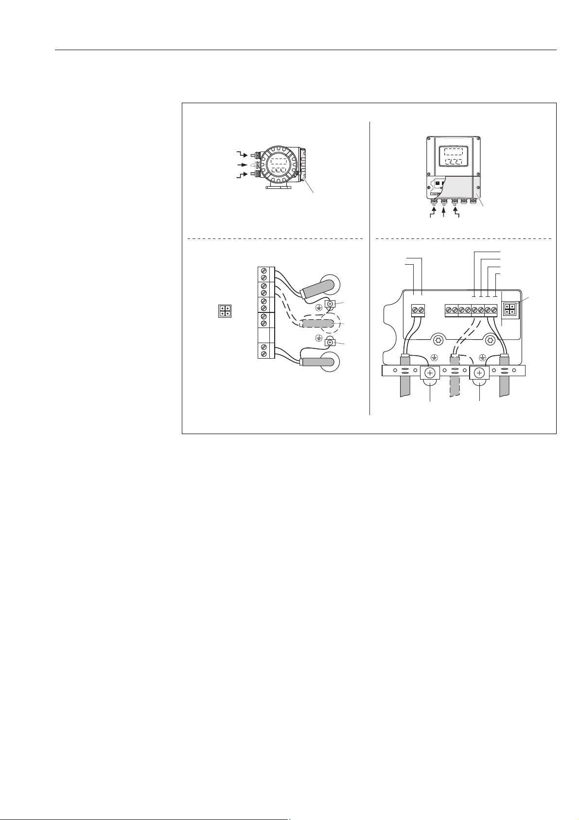
4.3.3 PROFIBUS DP connection diagram
a0005465
Fig. 22: Connecting the transmitter, cable cross-section: max. 2.5 mm (AWG 13)
A Field housing
B Wall-mount housing
a Connection compartment cover
b Power supply cable: 85 to 260 V AC, 20 to 55 V AC,16 to 62 V DC
Terminal No. 1: L1 for AC, L+ for DC
Terminal No. 2: N for AC, L- for DC
c Ground terminal for protective earth
d Fieldbus cable:
Terminal No. 26: B (RxD/TxD-P)
Terminal No. 27: A (RxD/TxD-N)
Observe the following:
e Ground terminal for fieldbus cable shield
– the shielding and grounding of the fieldbus cable ä 28
– that the stripped and twisted lengths of cable shield to the ground terminal are as short as possible
f Service socket for connecting service interface FXA 193 (FieldCare or Fieldcheck)
g Power supply cable for external termination (optional):
Terminal No. 24: +5 V
Terminal No. 25: DGND
Endress+Hauser 31
Page 32
Wiring Proline t-mass 65 PROFIBUS DP/PA
d
c
e
b
27
25
23
21
2
1
26
24
22
20
L1 (L+)
PA +
N (L-)
PA –
f
PA –
PA +
1
2
ce
f
b
d
222320 21 24
25
26
27
L1 (L+)
N (L–)
B
a
d
b
a
A
d
b
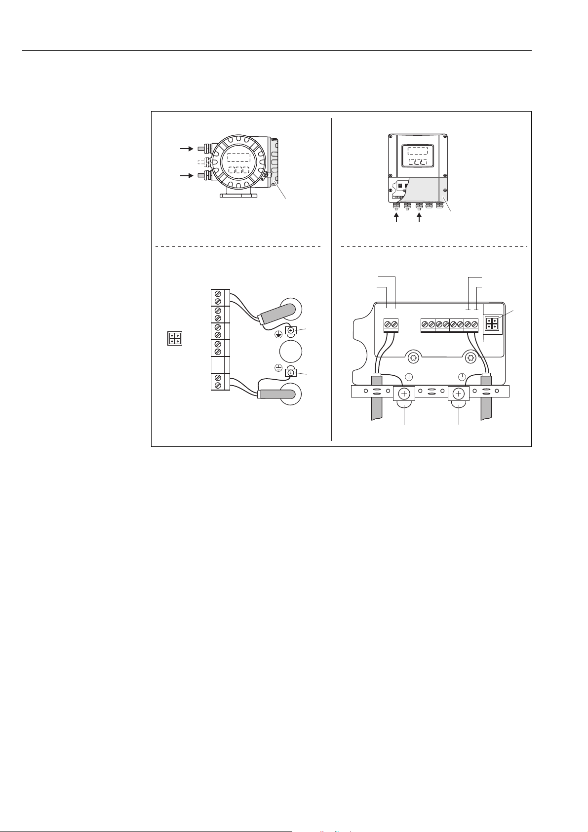
4.3.4 PROFIBUS PA connection diagram
A0005996
Fig. 23: Connecting the transmitter, cable cross-section max. 2.5 mm² (14 AWG)
A View A (field housing)
B View B (wall-mount housing)
a Cover of the connection compartment
b Cable for power supply: 85 to 260 V AC, 20 to 55 V AC,16 to 62 V DC
Terminal No. 1: L1 for AC, L+ for DC
Terminal No. 2: N for AC, L- for DC
c Ground terminal for protective ground
d Fieldbus cable:
Terminal No. 26: PA +, with reverse polarity protection
Terminal No. 27: PA –, with reverse polarity protection
e Fieldbus cable shield ground terminal
Please note the following:
– The shield and grounding of the fieldbus cable ä 28
– Make sure that the stripped and twisted lengths of cable shield to the ground terminal are kept as short as possible
f Service connector for connecting service interface FXA193 (Fieldcheck, FieldCare)
32 Endress+Hauser
Page 33
Proline t-mass 65 PROFIBUS DP/PA Wiring
PG 13.5
M12x1
150/300
(5.91/11.81)
45.0(1.77)
mm (inch)
CD E
3
4
2
1
G
5
6
4
1
2
F
3
7
B
C
D
E
A
Esc
E
-
+
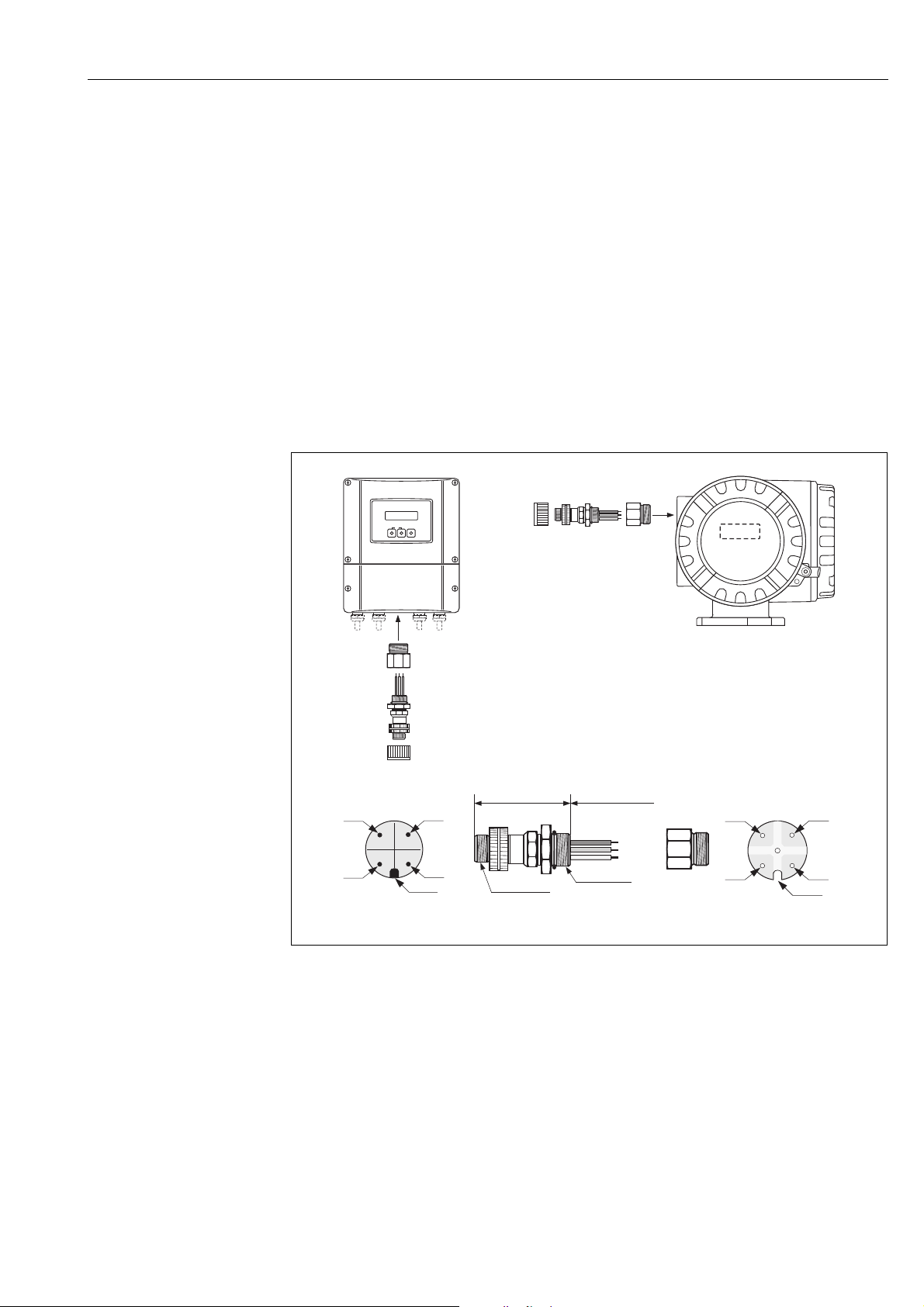
Fieldbus connector
!
Note!
The connector can only be used for PROFIBUS PA devices.
The connection technology of PROFIBUS PA allows measuring devices to be connected to the
fieldbus via uniform mechanical connections such as T-boxes, distribution modules etc.
This connection technology using prefabricated distribution modules and plug-in connectors offers
substantial advantages over conventional wiring:
• Field devices can be removed, replaced or added at any time during normal operation. Data
transmission is not interrupted.
• Installation and maintenance are significantly easier.
• Existing cable infrastructures can be used and expanded instantly, e.g. when constructing new
star distributors using 4-channel or 8-channel distribution modules.
The measuring device can therefore be supplied with the option of a ready-mounted fieldbus
connector. Fieldbus connectors for retrofitting can be ordered from Endress+Hauser as a spare part
ä 87.
Fig. 24: Connectors for connecting to the PROFIBUS PA
A Aluminum field housing
B Stainless steel field housing
Endress+Hauser 33
C Protection cap for connector
D Fieldbus connector
E Adapter PG 13.5 / M 20.5
F Connector at housing (male)
G Female connector
Pin assignment / color codes:
1 Brown wire: PA + (terminal 26)
2 Not connected
3 Blue wire: PA – (terminal 27)
4 Black wire: ground (instructions for connection ä 32)
5 Middle female connector not assigned
6 Positioning groove
7 Positioning key
a0005999
Page 34
Wiring Proline t-mass 65 PROFIBUS DP/PA
ab
4.4 Degree of protection
The devices fulfill all the requirements for IP 67 (NEMA 4X).
Compliance with the following points is mandatory following installation in the field or servicing,
in order to ensure that IP 67 (NEMA 4X) protection is maintained:
• The housing seals must be clean and undamaged when inserted into their grooves. The seals must
be dried, cleaned or replaced if necessary.
• All threaded fasteners and screw covers must be firmly tightened.
• The cables used for connection must be of the specified outside diameter (Cable entry ä 109)
• Firmly tighten the cable entries (a).
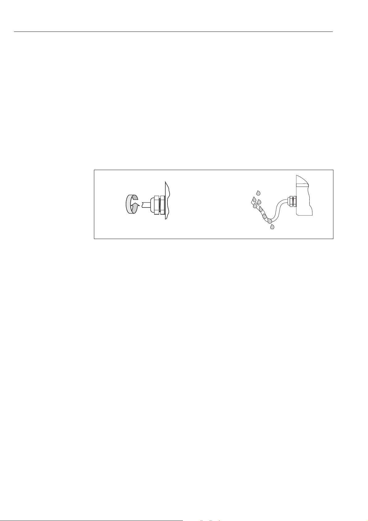
• The cables must loop down before they enter the cable entries ("water trap") (b). This
arrangement prevents moisture penetrating the entry. Always install the measuring device in such
a way that the cable entries do not point up.
• Remove all unused cable entries and insert blanking plugs instead.
• Do not remove the grommet from the cable entry.
Fig. 25: Installation instructions, cable entries
a0001914
34 Endress+Hauser
Page 35
Proline t-mass 65 PROFIBUS DP/PA Wiring
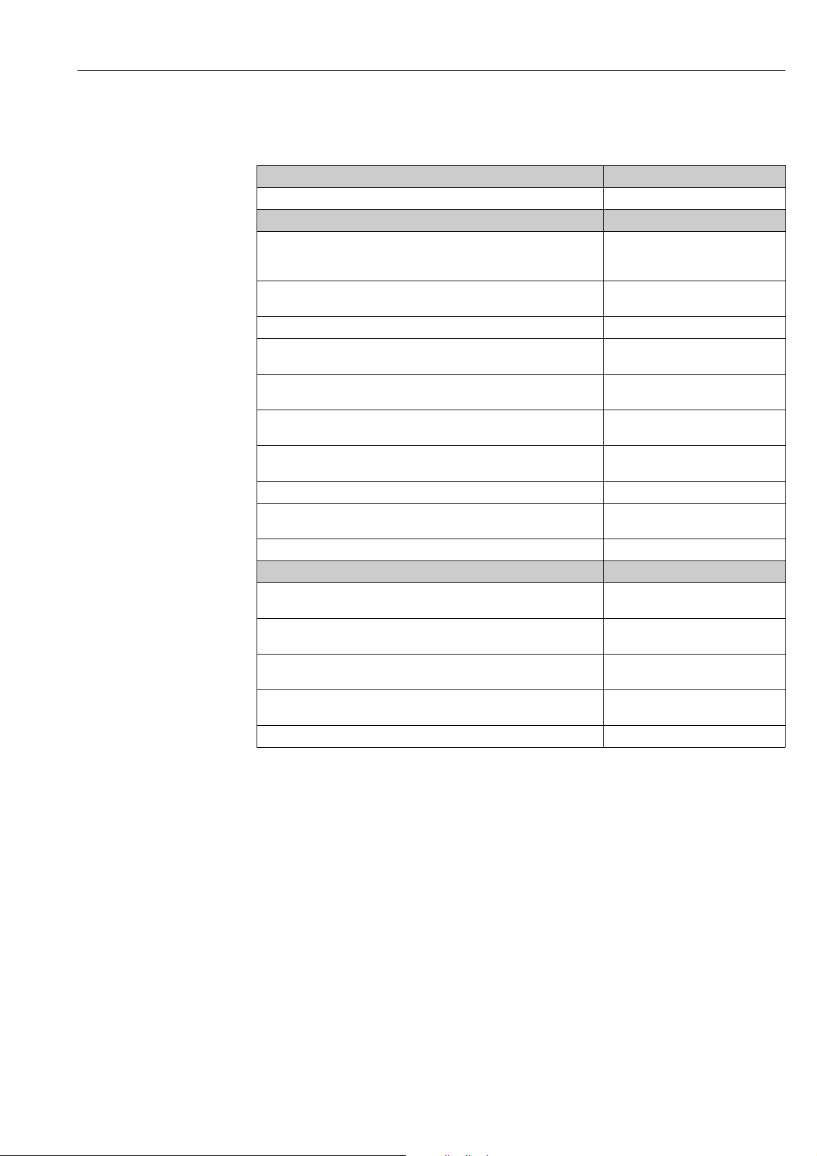
4.5 Post-connection check
Perform the following checks after completing electrical installation of the measuring device:
Device condition and specifications Notes
Are cables or the device damaged (visual inspection)? -
Electrical connection Notes
Does the supply voltage match the specifications on the nameplate? 85 to 260 V AC (45 to 65 Hz)
Do the cables comply with the specifications? PROFIBUS DP ä 27
Do the cables have adequate strain relief? -
Cables correctly segregated by type?
Without loops and crossovers?
Are the power supply and signal cables correctly connected? See the wiring diagram inside the cover
Only remote version: Is the flow sensor connected to the matching transmitter
electronics?
Only remote version: is the connecting cable between sensor and transmitter
connected correctly?
Are all screw terminals firmly tightened? -
Are all cable entries installed, firmly tightened and correctly sealed?
Cables looped as "water traps"?
Are all housing covers installed and firmly tightened? -
Electrical connection, PROFIBUS Notes
Are all the connecting components (T-boxes, junction boxes, connectors, etc.)
connected with each other correctly?
Has each fieldbus segment been terminated at both ends with a bus
terminator?
Has the max. length of the fieldbus cable been observed in accordance with
the PROFIBUS specifications?
Has the max. length of the spurs been observed in accordance with the
PROFIBUS specifications?
Is the fieldbus cable fully shielded and correctly grounded? ä 28
20 to 55 V AC (45 to 65 Hz)
16 to 62 V DC
Sensor cable ä 29
-
of the terminal compartment
Check serial number on nameplates of
sensor and connected transmitter.
ä 29
ä 34
-
ä 45
ä 27
ä 28
Endress+Hauser 35
Page 36
Operation Proline t-mass 65 PROFIBUS DP/PA
2A
3
1
Esc
E
-
+
Esc
E
+
-
XXX.XXX.XX
Esc
E
-
+
FXA193
2B
5Operation
5.1 Quick operation guide
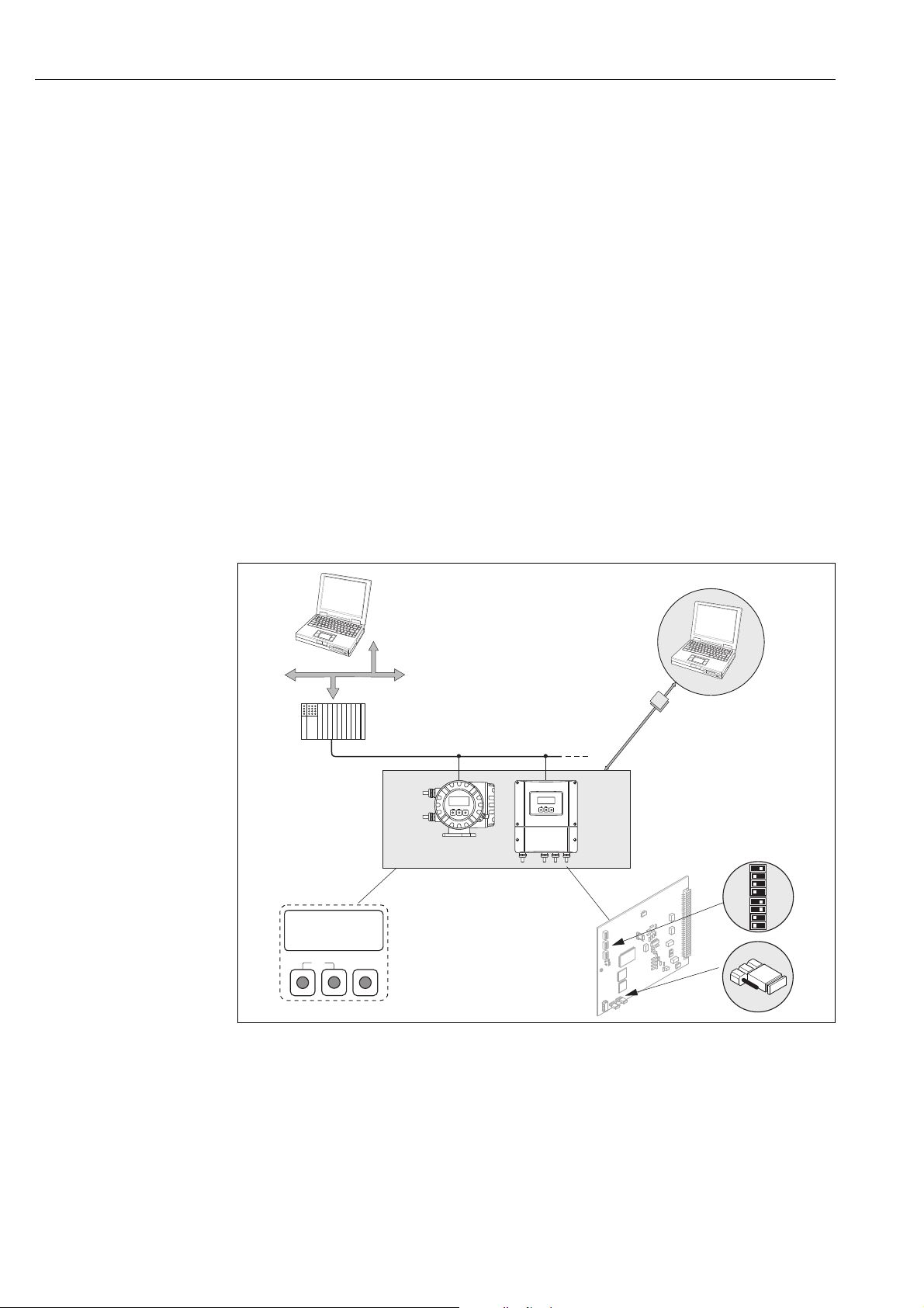
The user has a number of options for configuring and commissioning the device:
1. Local display (option) ä 37
The local display enables you to read all important variables directly at the measuring point,
configure device-specific parameters in the field and perform commissioning.
2. Configuration programs ä 41
The configuration of profile and device-specific parameters is primarily done via the PROFIBUS
interface. You can obtain special configuration and operating programs from various
manufacturers for these purposes.
3. Jumpers/miniature switches for hardware settings
–PROFIBUS DP ä 43
–PROFIBUS PA ä 46
You can make the following hardware settings using a jumper or miniature switches on the
I/O board:
• Address mode configuration (select software or hardware addressing)
• Device bus address configuration (for hardware addressing)
• Hardware write protection enabling/disabling
Fig. 26: Methods of operating PROFIBUS
1 Local display for device operation in the field (option)
2A Configuration/operating programs (e.g. FieldCare) for operation via PROFIBUS DP/PA
2B Configuration/operating program for operation via service interface FXA193 (e.g. FieldCare)
3 Jumper/miniature switches for hardware settings (write protection, device address, address mode)
36 Endress+Hauser
a0001318
Page 37
Proline t-mass 65 PROFIBUS DP/PA Operation
Esc
E
+
-
1
32
+48.25 xx/yy
+3702.6 x
5.2 Local display
5.2.1 Display and operating elements
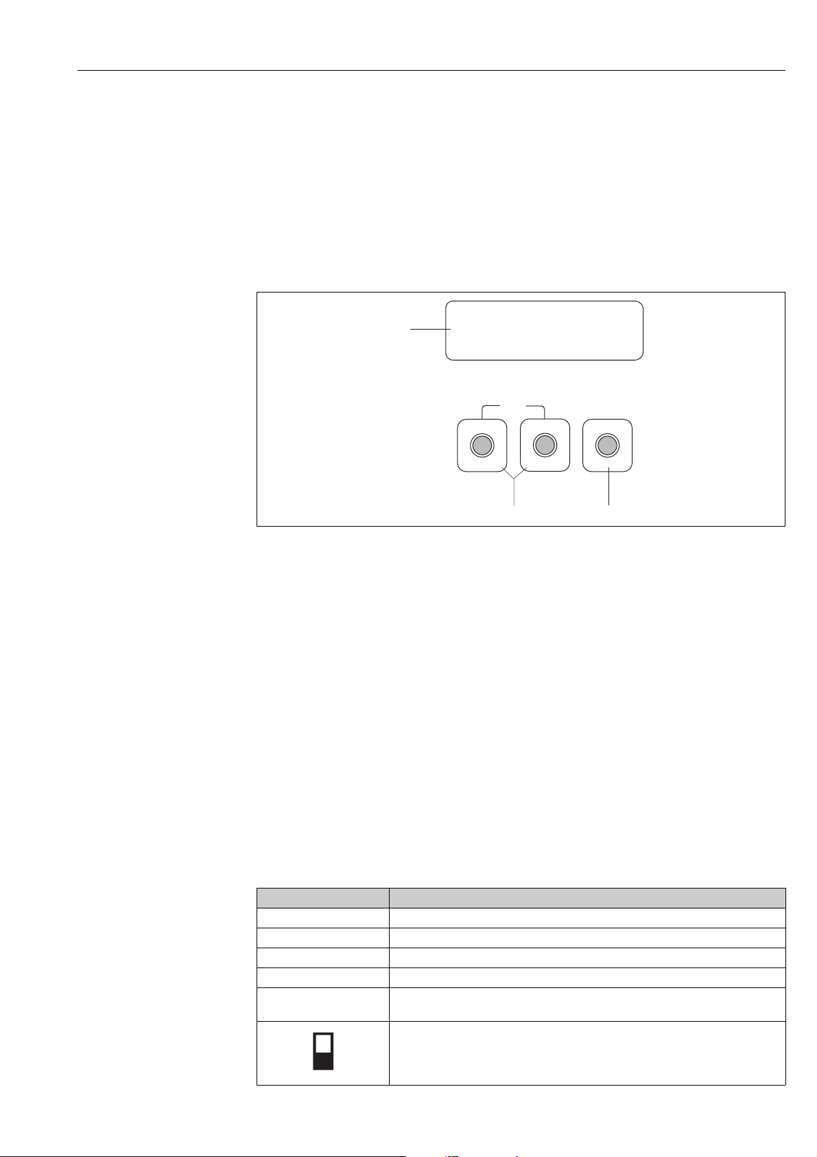
The local display enables you to read all important parameters directly at the measuring point and
configure the device.
The display area consists of two lines; this is where measured values are displayed, and/or status
variables (direction of flow, partially filled pipe, bar graph, etc.). You can change the assignment
of display lines to variables at will in order to customize the display to suit your needs and
preferences ( "Description of Device Functions" manual).
A0001141
Fig. 27: Display and operating elements
1 Liquid crystal display
The two-line liquid-crystal display shows measured values, dialog texts, error messages and information messages.
The display as it appears when normal measuring is in progress is known as the HOME position (operating mode).
– Upper display line: Shows primary measured values, e.g. volume flow in [ml/min] or in [%].
– Lower display line: Shows supplementary measured variables and status variables, e.g. totalizer reading in [m3],
bar graph, measuring point designation
2 Plus/minus keys
– Enter numerical values, select parameters
– Select different function groups within the function matrix
Press the +/- keys simultaneously to trigger the following functions:
– Exit the function matrix step by step HOME position
– Press and hold down +/- keys for longer than 3 seconds Return directly to HOME position
– Cancel data entry
3 Enter key
–HOME position Entry into the function matrix
– Save the numerical values you input or settings you change
5.2.2 Icons
The icons which appear in the field on the left make it easier to read and recognize measured
variables, device status, and error messages.
Icons Meaning
S System error
! Notice message
P Process error
$ Fault message
Cyclic communication via PROFIBUS active, e.g. via PLC (master Class 1)
(alternating display)
Acyclic communication via PROFIBUS active, e.g. via FieldCare
a0001206
Endress+Hauser 37
Page 38
Operation Proline t-mass 65 PROFIBUS DP/PA
>3s
-
+
E
Esc
E
E
E
E
E E E E E
–
+
+
Esc
–
+
Esc
–
+
Esc
–
E
m
n
o
p
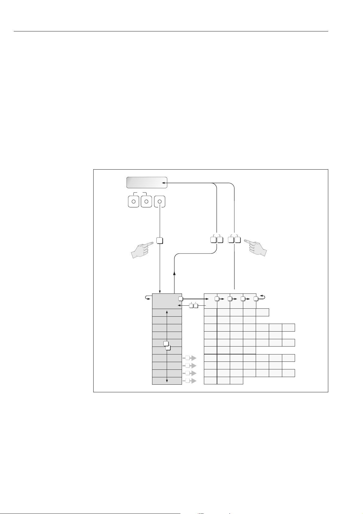
5.3 Brief operating instructions to the function matrix
!
Note!
• See the general notes ä 39.
• Function descriptions see the "Description of Device Functions" manual
1. HOME position F Entry into the function matrix
2. Select a function group (e.g. CURRENT OUTPUT 1)
3. Select a function (e.g. TIME CONSTANT)
Change parameter / enter numerical values:
OS Select or enter enable code, parameters, numerical values
F Save your entries
4. Exit the function matrix:
– Press and hold down Esc key (X) for longer than 3 seconds HOME position
– Repeatedly press Esc key (X) Return step by step to HOME position
Fig. 28: Selecting functions and configuring parameters (function matrix)
38 Endress+Hauser
a0001142
Page 39

Proline t-mass 65 PROFIBUS DP/PA Operation
5.3.1 General notes
The Quick Setup menu ( ä 48) contains the default settings that are adequate for commissioning.
Complex measuring operations on the other hand necessitate additional functions that you can
configure as necessary and customise to suit your process parameters. The function matrix,
therefore, comprises a multiplicity of additional functions which, for the sake of clarity, are arranged
in a number of function groups.
Comply with the following instructions when configuring functions:
• You select functions as described already. ä 38
• You can switch off certain functions (OFF). If you do so, related functions in other function groups
will no longer be displayed.
• Certain functions prompt you to confirm your data entries. Press P to select "SURE ( YES )" and
press F to confirm. This saves your setting or starts a function, as applicable.
• Return to the HOME position is automatic if no key is pressed for 5 minutes.
• Programming mode is disabled automatically if you do not press a key within 60 seconds
following automatic return to the HOME position.
!
"
"
Note!
• The transmitter continues to measure while data entry is in progress, i.e. the current measured
values are output via the signal outputs in the normal way.
• If the power supply fails, all preset and parameterised values remain safely stored in the EEPROM.
Caution!
All functions are described in detail, as is the function matrix itself, in the "Description of Device
Functions" manual, which is a separate part of these Operating Instructions.
5.3.2 Enabling the programming mode
The function matrix can be disabled. Disabling the function matrix rules out the possibility of
inadvertent changes to device functions, numerical values or factory settings. A numerical code
(factory setting = 65) has to be entered before settings can be changed.
If you use a code number of your choice, you exclude the possibility of unauthorised persons
accessing data ( see the "Description of Device Functions" manual).
Comply with the following instructions when entering codes:
• If programming is disabled and the P operating elements are pressed in any function, a prompt
for the code automatically appears on the display.
• If "0" is entered as the customer's code, programming is always enabled.
• Your Endress+Hauser representative can be of assistance if you mislay your personal code.
Caution!
Changing certain parameters such as all sensor characteristics, for example, influences numerous
functions of the entire measuring system, particularly measuring accuracy.
There is no need to change these parameters under normal circumstances and consequently, they
are protected by a special code known only to the Endress+Hauser representative. Please contact
Endress+Hauser if you have any questions.
5.3.3 Disabling the programming mode
Programming mode is disabled if you do not press an operating element within 60 seconds following
automatic return to the HOME position.
You can also disable programming in the "ACCESS CODE" function by entering any number (other
than the customer's code).
Endress+Hauser 39
Page 40
Operation Proline t-mass 65 PROFIBUS DP/PA
1
2453
XXXXXXXXXX
#000 00:00:05
P
5.4 Error messages
5.4.1 Type of error
Errors that occur during commissioning or measuring are displayed immediately. If two or more
system or process errors occur, the error with the highest priority is the one shown on the display.
The measuring system distinguishes between two types of error:
• System error: This group includes all device errors, e.g. communication errors, hardware errors,
etc. ä 90
• Process error: This group includes all application errors, e.g. flow limit, etc. ä 97
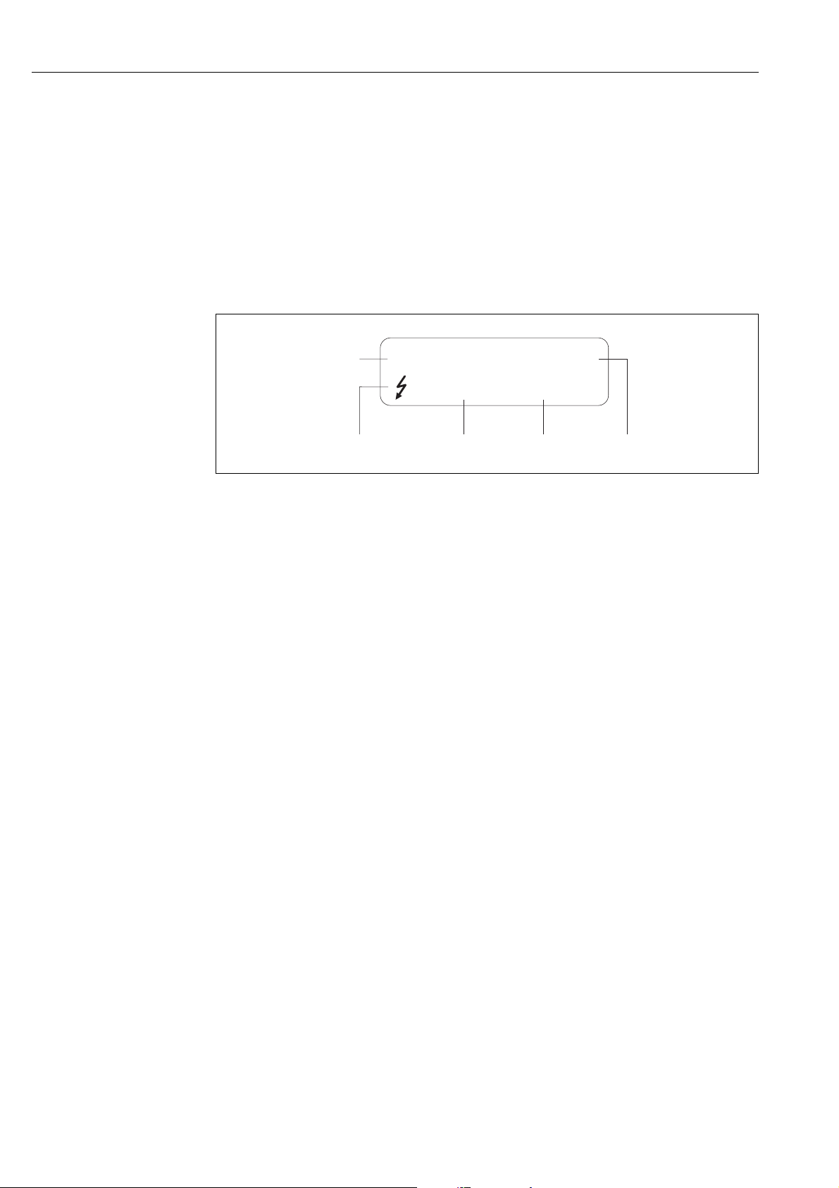
a0000991
Fig. 29: Error messages on the display (example)
1 Error type: P = process error, S = system error
2 Error message type: $ = fault message, ! = notice message, definition
3 Error designation: e.g. FLOW LIMIT = maximum flow limit exceeded
4 Error number: e.g. #422
5 Duration of most recent error occurrence (in hours, minutes and seconds)
5.4.2 Error message type
The measuring device always assigns system and process errors which occur to two types of error
messages (fault or notice messages) resulting in different weightings. ä 89
Serious system errors, e.g. module defects, are always identified and classed as "fault messages" by
the measuring device.
Notice message (!)
• The error in question has no effect on the current operation.
• Displayed as Exclamation mark (!), error type (S: system error, P: process error).
• Displaying the device status on PROFIBUS DP/PA ä 90
Fault message ( $ )
• The error in question interrupts or stops the current operation.
• Displayed as Lightening flash ( $ ), error type (S: system error, P: process error)
• Displaying the device status on PROFIBUS DP/PA ä 90
40 Endress+Hauser
Page 41
Proline t-mass 65 PROFIBUS DP/PA Operation
5.5 Operating options
5.5.1 FieldCare
FieldCare is Endress+Hauser’s FDT-based plant Asset Management Tool and allows the
configuration and diagnosis of intelligent field devices. By using status information, you also have a
simple but effective tool for monitoring devices. The Proline flow measuring devices are accessed
via a service interface or via the service interface FXA193.
5.5.2 Operating program "SIMATIC PDM" (Siemens)
SIMATIC PDM is a standardised, manufacturer-independent tool for the operation, configuration,
maintenance and diagnosis of intelligent field devices.
5.5.3 Current device description files
PROFIBUS DP
The following table illustrates the suitable device description file for the operating tool in question
and then indicates where these can be obtained.
Valid for device software: 3.06.XX Function DEVICE SOFTWARE
PROFIBUS DP device data:
Profile Version:
t-mass 65 ID No.:
Profile ID No.:
GSD file information:
t-mass 65 GSD file: Extended format (recommended):
Profile GSD file: PA039740.gsd
Bitmaps: EH_1545_d.bmp/.dib
Software release: 10.2010
Operating program Sources for obtaining device descriptions
t-mass 65 GSD file • www.endress.com Download
Profile GSD file • www.profibus.com
FieldCare / DTM
SIMATIC PDM • www.endress.com Download
3.0
1545hex
9740hex
Standard format:
Note!
!
When planning and configuring the PROFIBUS network, please observe the information
on using GSD files ä 61 ff.
EH_1545_n.bmp/.dib
EH_1545_s.bmp/.dib
• www.endress.com Download
• CD–ROM (Endress+Hauser order number: 56004088)
• DVD (Endress+Hauser order number: 70100690)
Function PROFILE VERSION
Function DEVICE ID
eh3x1545.gsd
eh3_1545.gsd
Tester/simulator:
Measuring device: How to acquire:
!
Fieldcheck Update by means of FieldCare with the Flow Device FXA193/291 DTM in
Note!
The Fieldcheck tester/simulator is used for testing flowmeters in the field. When used in
the Fieldflash module.
conjunction with the "FieldCare" software package, test results can be imported into a database,
printed out and used for official certification. Contact your Endress+Hauser representative for more
information.
Endress+Hauser 41
Page 42
Operation Proline t-mass 65 PROFIBUS DP/PA
PROFIBUS PA
Valid for device software: 3.06.XX Function DEVICE SOFTWARE
PROFIBUS DP device data:
Profile Version:
t-mass 65 ID No.:
Profile ID No.:
GSD file information:
t-mass 65 GSD file: Extended format (recommended):
Profile GSD file: PA039740.gsd
Bitmaps: EH_1550_d.bmp/.dib
Software release: 10.2010
Operating program Sources for obtaining device descriptions
t-mass 65 GSD file • www.endress.com Download
Profile GSD file • www.profibus.com
FieldCare / DTM
SIMATIC PDM • www.endress.com Download
3.0
1550hex
9740hex
Standard format:
Note!
!
When planning and configuring the PROFIBUS network, please observe the information
on using GSD files ä 61 ff.
EH_1550_n.bmp/.dib
EH_1550_s.bmp/.dib
• www.endress.com Download
• CD–ROM (Endress+Hauser order number: 56004088)
• DVD (Endress+Hauser order number: 70100690)
Function PROFILE VERSION
Function DEVICE ID
eh3x1550.gsd
eh3_1550.gsd
!
Tester/simulator:
Measuring device: How to acquire:
Fieldcheck Update by means of FieldCare with the Flow Device FXA193/291 DTM in
the Fieldflash module.
Note!
The Fieldcheck tester/simulator is used for testing flowmeters in the field. When used in
conjunction with the "FieldCare" software package, test results can be imported into a database,
printed out and used for official certification. Contact your Endress+Hauser representative for more
information.
42 Endress+Hauser
Page 43
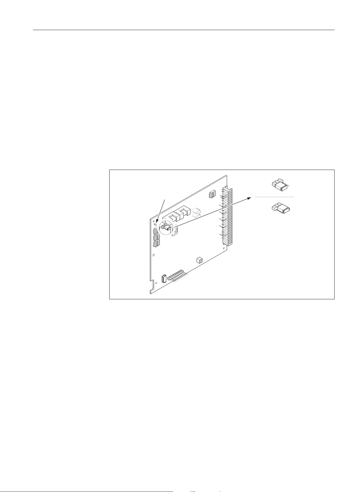
Proline t-mass 65 PROFIBUS DP/PA Operation
1
2
3
4
W
E
N
O
1
2
3
4
W
E
N
O
1
2
3
4
W
E
N
O
1
2
3
4
W
E
N
O
1.1
1.2
1
LED
5.6 PROFIBUS DP hardware settings
5.6.1 Configuring the write protection
A jumper on the I/O board provides the means of switching hardware write protection on or off.
When the hardware write protection is switched on, it is not possible to write to the device
parameters via PROFIBUS (acyclic data transmission, e.g. via operating program "FieldCare").
#
Warning!
Risk of electric shock. Exposed components carry dangerous voltages. Make sure that the power
supply is switched off before you remove the cover of the electronics compartment.
1. Switch off power supply.
2. Remove the I/O board.
3. Configure the hardware write protection accordingly with the aid of the jumpers (see Figure).
4. Installation is the reverse of the removal procedure.
a0005407
Fig. 30: Switching write protection on and off with the aid of a jumper on the I/O board
1 Jumper for switching write protection on and off
1.1 Write protection switched on (factory setting) = it is not possible to write to the device parameters via PROFIBUS
(acyclic data transmission, e.g. via operating program "FieldCare")
1.2 Write protection switched off = it is possible to write to the device parameters via PROFIBUS (acyclic data
transmission, e.g. via operating program "FieldCare")
LED Overview of LED status:
– Lit continuously Ready for operation
– Not lit Not ready for operation
– Flashing System or process error present ä 89
Endress+Hauser 43
Page 44
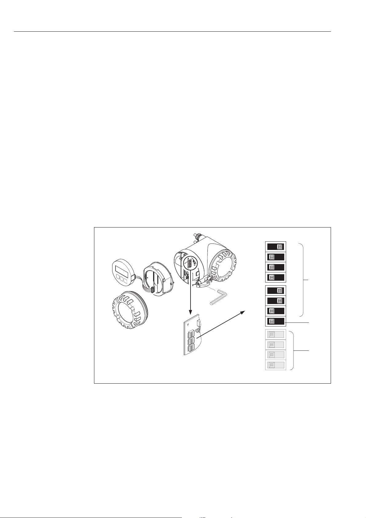
Operation Proline t-mass 65 PROFIBUS DP/PA
1
2
3
4
W
E
N
O
1
2
3
4
W
E
N
O
1
2
3
4
W
E
N
O
1
2
3
4
W
E
N
O
1
2
3
4
W
E
N
O
1
2
3
4
W
E
N
O
161
3
322
4
643
4
1
2
b
OFF ON
11
22
43
84
a
OFF ON
c
5.6.2 Configuring the device address
The address must always be configured for a PROFIBUS DP measuring device. The valid device
addresses are in the range from 1 to 126. In a PROFIBUS DP network, each address can only be
assigned once. If an address is not configured correctly, the device is not recognized by the master.
All measuring devices are delivered from the factory with the address 126 and software addressing.
Addressing via local operation or operating program
Addressing takes place in the FIELDBUS ADDRESS function see "Description of Device
Functions" manual.
Addressing via miniature switches
#
Warning!
Risk of electric shock. Exposed components carry dangerous voltages. Make sure that the power
supply is switched off before you remove the cover of the electronics compartment.
1. Loosen Allen screw (3 mm) of the securing clamp.
2. Unscrew cover of the electronics compartment from the transmitter housing.
3. Remove the local display (if present) by loosening the set screws of the display module.
4. Set the position of the miniature switches on the I/O board using a sharp pointed object.
5. Installation is the reverse of the removal procedure.
Fig. 31: Addressing with the aid of miniature switches on the I/O board
a Miniature switches for setting the device address (illustrated: 1 + 16 + 32 = device address 49)
b Miniature switches for the address mode (method of addressing):
OFF = software addressing via local operation or operating program (factory setting)
ON = hardware addressing via miniature switches
c Miniature switches not assigned
44 Endress+Hauser
a0002821
Page 45
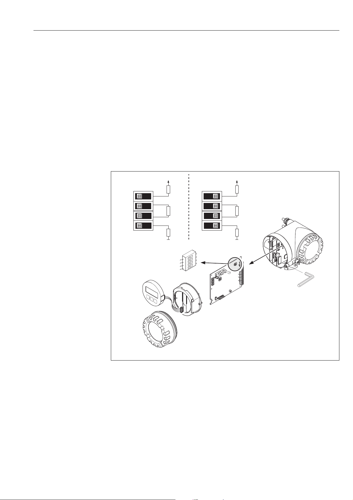
Proline t-mass 65 PROFIBUS DP/PA Operation
1
2
3
4
W
E
N
O
1
2
3
4
W
E
N
O
1
2
3
4
W
E
N
O
1
2
3
4
W
E
N
O
1
2
3
4
W
E
N
O
1
2
3
4
W
E
N
O
1
2
3
4
W
E
N
O
1
2
3
4
W
E
N
O
1
2
3
4
W
E
N
O
390 W
+5V
A
3
4
1
2
OFF ON
220W
390 W
SW1
390 W
+5V
B
3
4
1
2
OFF ON
220W
390 W
SW1
5.6.3 Configuring the terminating resistors
!
#
Note!
It is important to terminate the RS485 line correctly at the start and end of the bus segment since
impedance mismatch results in reflections on the line which can cause faulty data transfer.
Warning!
Risk of electric shock. Exposed components carry dangerous voltages.
Make sure that the power supply is switched off before you remove the cover of the electronics
compartment.
• For baudrates up to 1.5 MBaud, the termination is set via the terminating switch SW 1 for the
last transmitter on the bus: ON – ON – ON – ON.
• The measuring device is operated with a baudrate >1.5 MBaud:
Due to the capacitive load of the device and the line reflection generated as a result, make sure
that external termination is used.
The miniature switch for termination is located on the I/O board (see Figure):
!
Fig. 32: Set terminating resistors (for baud rates < 1.5 MBaud)
A = Factory setting
B = Setting at the last transmitter
Note!
It is generally recommended to use external termination since if a device that is terminated
internally is defect, this can result in the failure of the entire segment.
a0005408
Endress+Hauser 45
Page 46
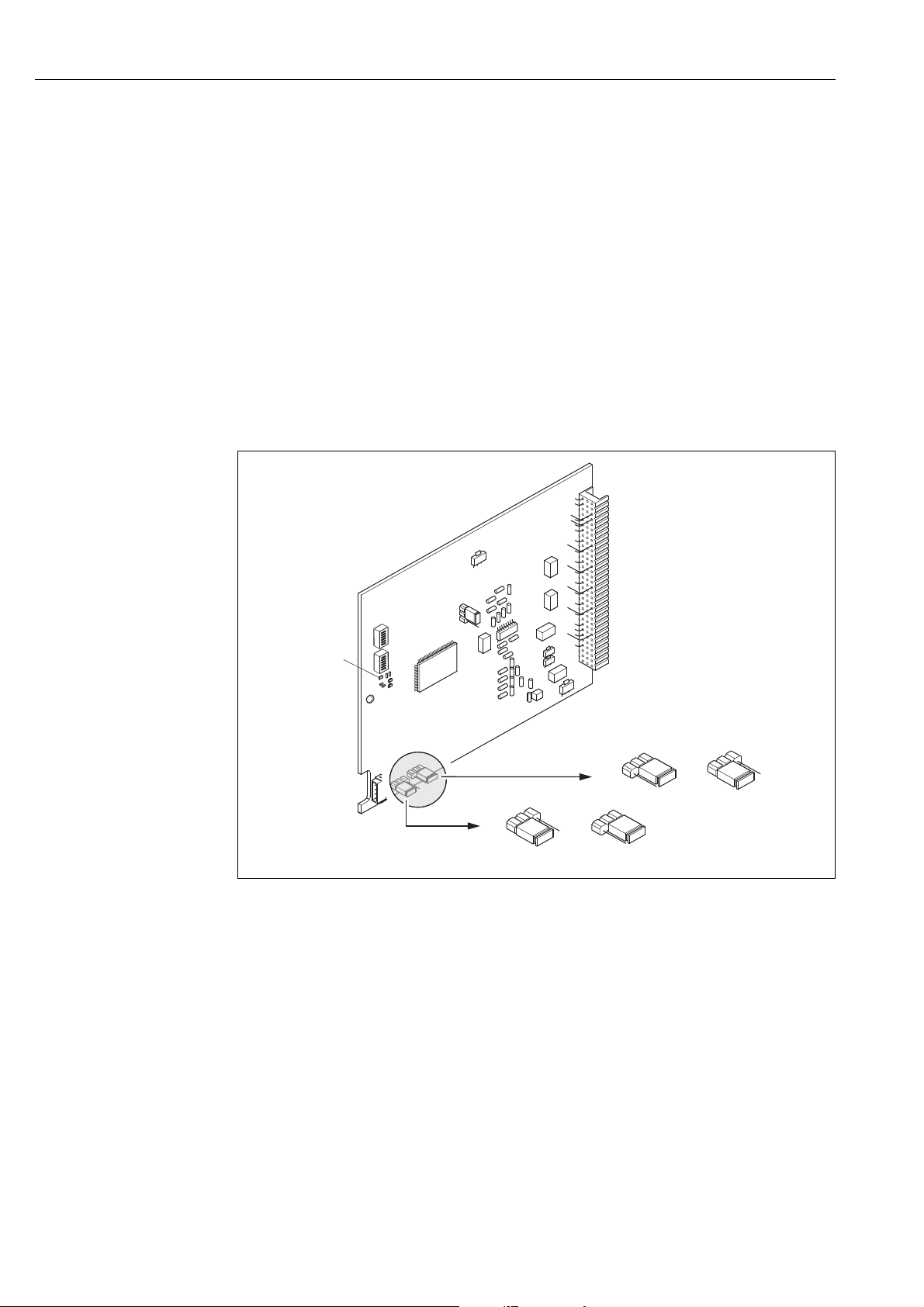
Operation Proline t-mass 65 PROFIBUS DP/PA
1
1.21.1
2
LED
5.7 PROFIBUS PA hardware settings
5.7.1 Configuring the write protection
A jumper on the I/O board provides the means of switching hardware write protection on or off.
When hardware write protection is switched on, it is not possible to write to the device functions
via PROFIBUS (acyclic data transmission, e.g. via the operating program "FieldCare").
#
Warning!
Risk of electric shock. Exposed components carry dangerous voltages. Make sure that the power
supply is switched off before you remove the cover of the electronics compartment.
1. Switch off power supply.
2. Remove the I/O board.
3. Configure the hardware write protection accordingly with the aid of the jumpers (see Figure).
4. Installation is the reverse of the removal procedure.
Fig. 33: Switching write protection on and off with the aid of a jumper on the I/O board
1 Jumper for switching write protection on and off
1.1 Write protection switched on = it is not possible to write to the device functions via PROFIBUS (acyclic data
transmission, e.g. via the operating program "FieldCare")
1.2 Write protection switched off (factory setting) = it is possible to write to the device functions via PROFIBUS
(acyclic data transmission, e.g. via the operating program "FieldCare")
2 Jumper without function
LED Overview of LED states:
– Lit continuously Ready for operation
–Not lit Not ready for operation
– Flashing System or process error present ä 89
46 Endress+Hauser
a0001359
Page 47
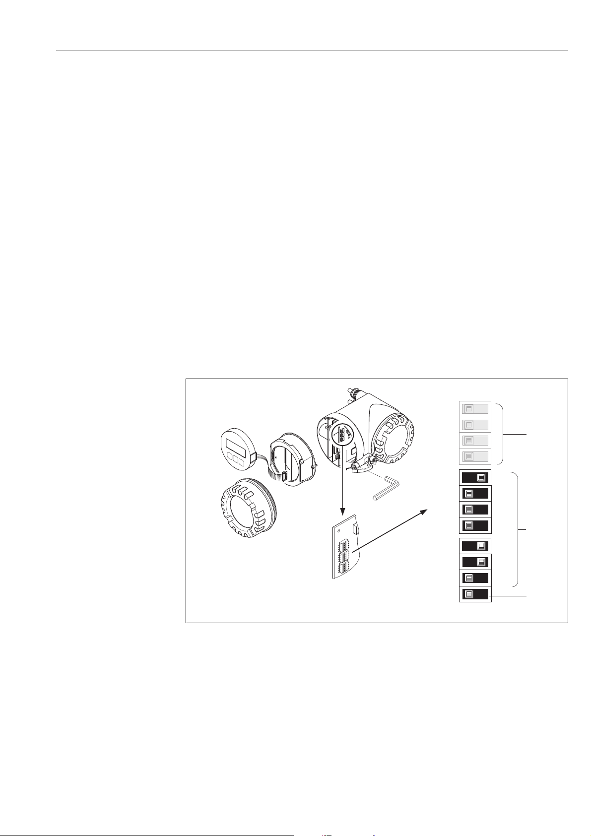
Proline t-mass 65 PROFIBUS DP/PA Operation
1
2
3
4
W
E
N
O
1
2
3
4
W
E
N
O
1
2
3
4
W
E
N
O
161
3
322
4
643
4
1
2
b
OFF ON
11
22
43
84
a
OFF ON
c
1
2
3
4
W
E
N
O
1
2
3
4
W
E
N
O
1
2
3
4
W
E
N
O
5.7.2 Configuring the device address
The address must always be configured for a PROFIBUS DP/PA device. The valid device addresses
are in the range from 1 to 126. In a PROFIBUS DP/PA network, each address can only be assigned
once. If an address is not configured correctly, the device is not recognized by the master. All
measuring devices are delivered from the factory with the address 126 and with software
addressing.
Addressing via local operation/operating program
Addressing takes place in the FIELDBUS ADDRESS function see the "Description of Device
Functions" manual.
Addressing via miniature switches
#
Warning!
Risk of electric shock. Exposed components carry dangerous voltages. Make sure that the power
supply is switched off before you remove the cover of the electronics compartment.
1. Loosen the Allen screw (3 mm) of the securing clamp.
2. Unscrew cover of the electronics compartment from the transmitter housing.
3. Remove the local display (if present) by loosening the set screws of the display module.
4. Set the position of the miniature switches on the I/O board using a sharp pointed object.
5. Installation is the reverse of the removal procedure.
Fig. 34: Addressing with the aid of miniature switches on the I/O board
a Miniature switches for setting the device address (illustrated: 1 + 16 + 32 = device address 49)
b Miniature switches for the address mode (method of addressing):
OFF = software addressing via local operation/operating program (factory setting)
ON = hardware addressing via miniature switches
c Miniature switches not assigned
Endress+Hauser 47
a0002590
Page 48

Commissioning Proline t-mass 65 PROFIBUS DP/PA
6 Commissioning
6.1 Function check
Make sure that all final checks have been completed before you start up your measuring point:
• Checklist for "Post-installation check" ä 26
• Checklist for "Post-connection check" ä 35
6.2 Switching on the measuring device
Once the post-connection checks have been successfully completed, it is time to switch on the
supply voltage. The device is now operational.
The measuring device performs a number of power on self-tests. As this procedure progresses the
following sequence of messages appears on the local display:
!
!
t-mass 65
START-UP
▼
DEVICE SOFTWARE
V XX.XX.XX
▼
SYSTEM OK
OPERATION
▼
Normal measuring mode commences as soon as start-up completes.
Various measured values and/or status variables appear on the display (HOME position).
Note!
If start-up fails, an error message indicating the cause is displayed.
Start-up message
Current software version
Beginning of normal measuring mode
6.3 Quick Setup
All important device parameters for standard operation can be configured quickly and easily by
means of the Quick Setup menu, especially for devices that have been delivered with factory default
settings
Note!
If the measuring device has been ordered with customer-specific settings then the Quick Setup is
not necessary. Check that the parameterization protocol on the CD delivered with the device
matches your required data.
48 Endress+Hauser
Page 49
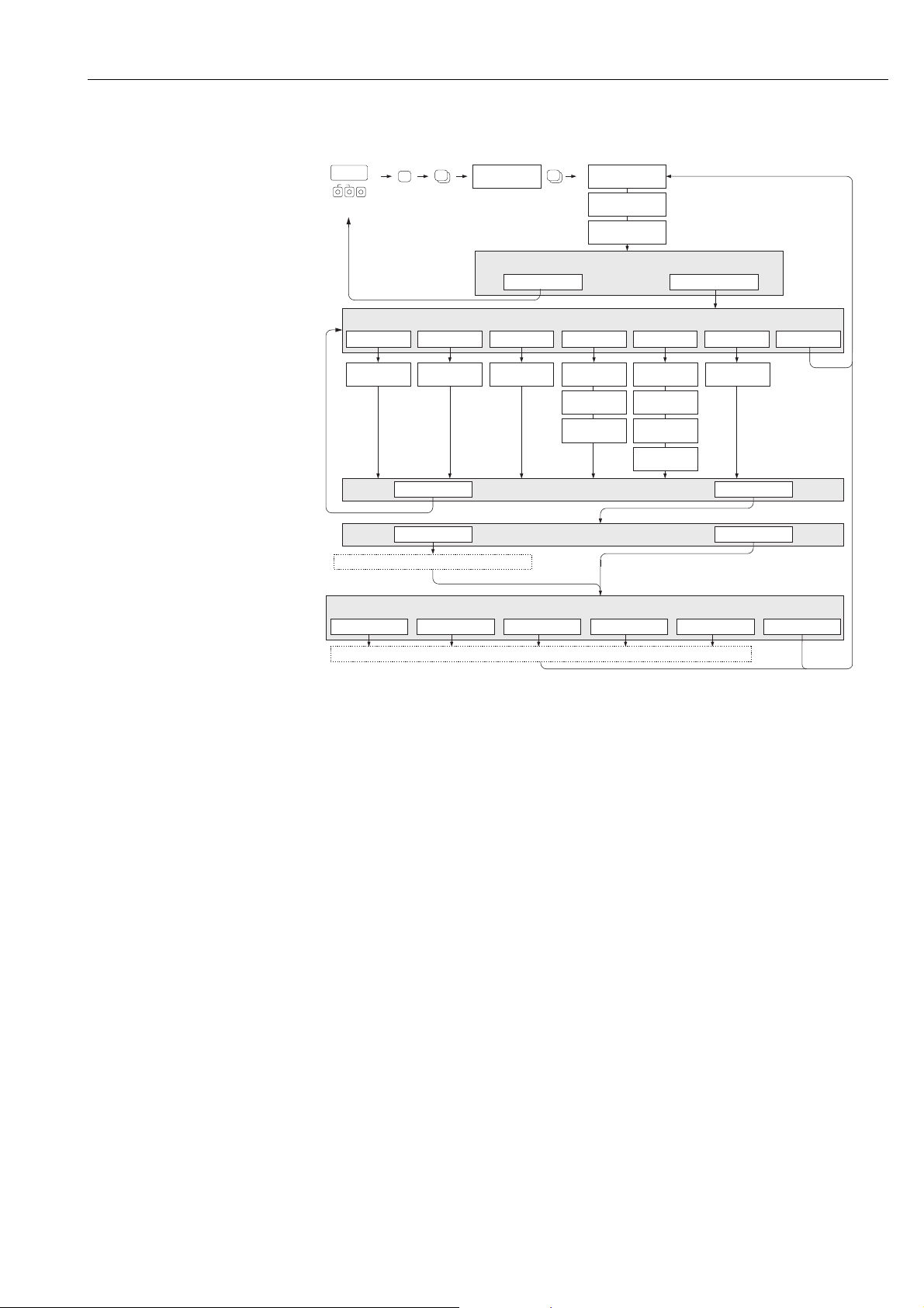
Proline t-mass 65 PROFIBUS DP/PA Commissioning
+
+
E
+
E
n
o
t
Esc
E
+
-
XXX.XXX.XX
m
u
Yes
Yes
No
No
Configure another system unit ?
Automatic configuration of display ?
Automatic parameterization of the display
Corr. Vol. FlowMass flow
Density
Selection system units
Temperature
Quit
Unit
Corr. Vol. Flow
Unit
Mass Flow
Unit
Density
Language
Pre-setting
Quick Setup
HOME-POSITION
QS
Commission
Unit
Temperature
Selection pre-settings
Reference
Temperature
Reference
Pressure
Delivery settings Actual settings
Heat Flow
Unit
Heat Flow
Unit
Quantity Heat
Pressure
Unit
Pressure
Sensor Gas
Carry out another Quick Setup
NoPressure Heat Flow
Carry out the selected Quick Setup
Unit Calorific
Value Mass
Unit Calorific
Val. Corr. Vol.
Communication
6.3.1 Quick Setup "Commissioning"
Fig. 35: QUICK SETUP COMMISSIONING- menu for straightforward configuration of the major device functions
!
Note!
The display returns to the QUICK SETUP cell if you press the ESC key combination (Q) during
programming of a parameter anywhere in the menu.
QUICK SETUP - COMMISSION
Use the O or S key at the prompt "QS-COMMISSION NO" and the device access code entry appears. Enter the device access
code "65" and press F; programming is enabled. The prompt "QS-COMMISSION NO" appears. Use the O or S key to
change NO to YES and press F.
LANGUAGE
Use the O or S key to select the required language and continue with F.
PRE-SETTING.
m Select ACTUAL SETTINGS to continue programming the device and go to the next level or select DELIVERY SETTINGS
to reset the device. The device restarts and returns to the Home position.
- ACTUAL SETTINGS are the actual programmed parameters in the device
- DELIVERY SETTINGS are the programmed parameters (factory settings plus customer
specific settings) originally delivered with the device
SYSTEM UNITS.
Select required system unit function and carry out parameterization or select QUIT to return to the QUICK SETUP function
if no further programming is required.
n Only units not yet configured in the current setup are available for selection in each cycle.
o The YES option remains visible until all the units have been configured.
NO is the only option displayed when no further units are available.
A0005458-en
Endress+Hauser 49
Page 50

Commissioning Proline t-mass 65 PROFIBUS DP/PA
Automatic configuration of the display
t The "automatic parameterization of the display" option contains the following basic settings/factory settings:
- YES: main line = MASS FLOW, additional line = TOTALIZER 1
- NO: The existing (selected) settings remain.
Carry out another Quick Setup?
u Select additional Quick Setups to complete commissioning or select NO to exit.
50 Endress+Hauser
Page 51
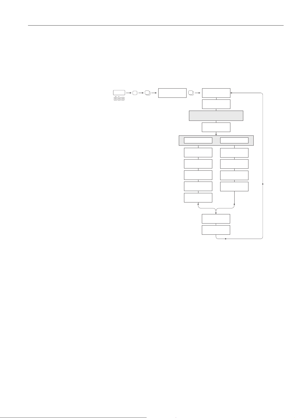
Proline t-mass 65 PROFIBUS DP/PA Commissioning
+
+
E
Esc
E
+
-
XXX.XXX.XX
HOME-POSITION
+
E
m
n
o
INSERTION
DEPH
MOUNTING SET
LENGTH
QUICK SETUP
QS
SENSOR
PIPE
STANDARD
INTERNAL
HEIGHT
NOMINAL
DIAMETER
INTERNAL
WIDTH
UNIT
LENGTH
WALL
THICKNESS
WALL
THICKNESS
MOUNTING
RECTANGULARCIRCULAR
OUTER
DIAMETER
INTERNAL
DIAMETER
PIPE
TYPE
Selection Pipe Type
6.3.2 Quick Setup "Sensor"
It is essential that the insertion sensor is setup according to the actual pipe or duct and then installed
at the calculated insertion depth. This Quick Setup guides you systematically through the procedure
to setup the sensor.
!
Note!
The QUICK SETUP SENSOR function is not available for flanged type sensors.
A0009910-en
PIPE TYPE
m • CIRCULAR
– in case that the pipe is of a standard type, then parameterize functions PIPE STANDARD and NOMINAL
DIAMETER
– In case that the pipe is a non-standard type, then select OTHERS in the function PIPE STANDARD and
parameterize the functions WALL THICKNESS and OUTER DIAMETER.
– The function INTERNAL DIAMETER displays the calculated internal diameter and is read only.
• RECTANGULAR
– Enter the INTERNAL HEIGHT, INTERNAL WIDTH and WALL THICKNESS of the duct
– Select the MOUNTING orientation of the sensor: HORIZONTAL or VERTICAL
MOUNTING SET LENGTH
n Enter the measured length of the mounting set (including the compression fitting) ä 19.
INSERTION DEPTH
o This function calculates the insertion depth value for the mounting of the sensor ä 19.
Press F to save settings and return to QUICK SETUP SENSOR group.
This function is read only.
Endress+Hauser 51
Page 52
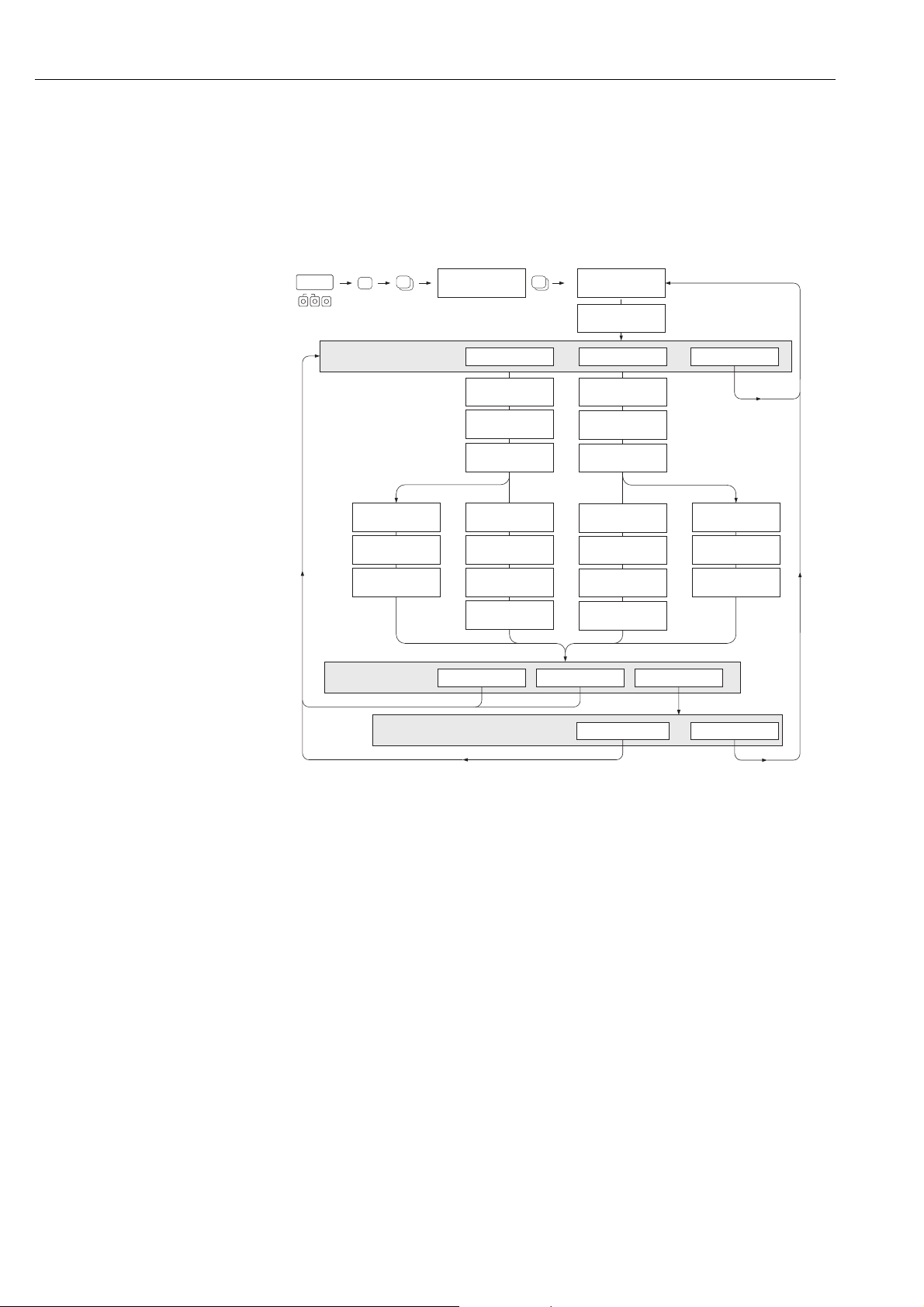
Commissioning Proline t-mass 65 PROFIBUS DP/PA
+
+
E
Esc
E
+
-
XXX.XXX.XX
HOME-POSITION
+
E
QUICK SETUP
QS
GAS
DESCRIPTION 1
CORRECTION
FACTOR1
REFERENCE
DENSITY1
GAS GROUP 1
NUMBER OF
GASES
GAS TYPE
2…8
MOLE % GAS
2…8
CHECK
VALUES
CANCEL
YES
NO
Selection
SAVECHANGES?
Selection of Gas Group
Configure Another Group?
DESCRIPTION 2
MOLE % GAS 1
MOLE % GAS 1
QUIT
GAS GROUP 2
NUMBER OF
GASES
GAS TYPE 1
GAS TYPE 1
GAS TYPE
2…8
MOLE % GAS
2…8
CHECK
VALUES
CORRECTION
FACTOR2
REFERENCE
DENSITY2
YESDISCARD
SELECT
GROUP
ANALYZER
INPUT
ANALYZER
INPUT
6.3.3 "Gas" Quick Setup menu
The device can be setup with 1 or 2 individual gas groups in memory. This means that up to 2
different gas flow streams (e.g. nitrogen and argon) can be measured in a single pipe with one
flowmeter.
In the case of 2 gas groups being used, a digital input can be assigned to switch between the gas
groups or, alternatively, the switch can be done manually via a function in the device software.
A0009907-en
Programming a gas group
The device allows flexible change of the gas group parameters, independent of the original factory
setup and calibration
A gas group can be programmed as:
– one single gas or
– one gas mixture (of up to 8 components)
A single gas can be:
– selected from a list of standard gases or
– setup for other suitable types of gases, such as Ozone, using manual correction factors and the
option called SPECIAL GAS. This requires application evaluation at the factory - consult your
Endress+Hauser representative prior to using this function.
52 Endress+Hauser
Page 53

Proline t-mass 65 PROFIBUS DP/PA Commissioning
Setting or viewing the active gas group
Go to the function SELECT GROUP and simply select 1 or 2 and then exit using ESC (+/- keys
simultaneously). No save function is necessary.
!
Note!
This Quick Setup Gas function is not available if an in-situ calibration function has been performed
on the device as the in-situ calibration curve refers to the sensor power at each recorded flow point.
Therefore, the programmed gas settings become redundant. ä 86
Performing the Quick Setup
1. GAS GROUP
Use the O or S key to select the required GAS GROUP and continue with F.
– select the NUMBER OF GASES in the group from 1 to 8
– select the GAS TYPE from the choose list.
– enter the MOLE % for each GAS TYPE (only if NUMBER OF GASES is 2 and more).
– The error message CHECK VALUES appears if the total mixture % does not equal 100%. Go
back and check the mixture settings.
2. SAVE CHANGES?
– Select YES to save changes to the GAS GROUP and activate them. Press F to continue or
– Select CANCEL to save the entered settings in buffer memory but not activate them for
measurement. If this function is selected, then it will be necessary to come back to this gas
group and save it at a later stage.
– Select DISCARD to clear the last changes and return to CONFIGURE GROUP to make new
settings.
!
3. ANOTHER GAS GROUP?
– Select YES to continue to the CONFIGURE GROUP function. Use the + or - key to select
another group and proceed as per above instructions.
– Select NO to exit to the Quick Setup.
Note!
You can find more detailed information on the GAS GROUP programming in the separate
"Description of Device Functions" manual BA00114D/06/… see chapter GAS 1/2.
Endress+Hauser 53
Page 54

Commissioning Proline t-mass 65 PROFIBUS DP/PA
+
+
E
Esc
E
+
-
XXX.XXX.XX
HOME-POSITION
+
E
QS
PRESSURE
PROCESS
PRESSURE 2
PROCESS
PRESSURE 1
QUICK SETUP
6.3.4 "Pressure" Quick Setup menu
Use this Quick Setup to program the individual process pressure for each gas group. If only one gas
group is being used, then only the function PROCESS PRESSURE 1 needs to be programmed,
PROCESS PRESSURE 2 can remain with default settings.
A0009908-en
!
Note!
• The device operates with absolute pressure only. Convert any gauge pressures to absolute
pressure.
• If a pressure compensating input is being used, then the input signal value overrides the manually
programmed value. The pressure input value applies to both gas groups. i.e. 2 independent
pressure values are no longer possible.
• This Quick Setup Gas function is not available if an in-situ calibration function has been
performed on the device as the in-situ calibration curve refers to the sensor power at each
recorded flow point. Therefore, the programmed pressure settings become redundant ä 86.
54 Endress+Hauser
Page 55
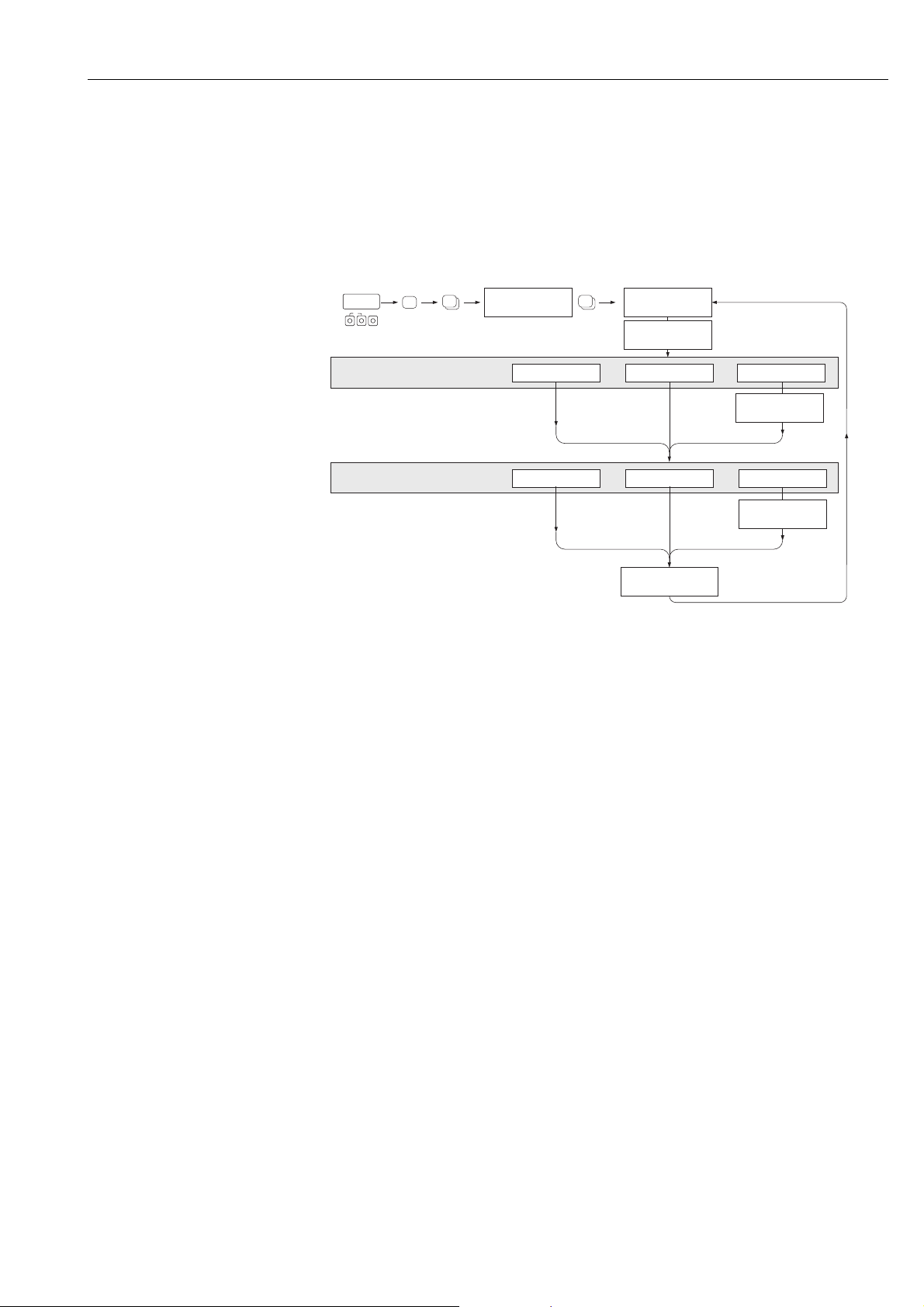
Proline t-mass 65 PROFIBUS DP/PA Commissioning
+
+
E
Esc
E
+
-
XXX.XXX.XX
HOME-POSITION
+
E
QUICK SETUP
QS
HEATFLOW
AUTONET
Selection CALCULATION MODE 1
MANUAL
AUTO GROSS
Selection CALCULATION MODE 2
AUTONET
MANUAL
AUTO GROSS
CALORIFIC
VALUE2
CALORIFIC
VALUE1
CALORIFIC
VALUETYPE
REF. COMBUST.
TEMPERATURE
6.3.5 "Heat Flow" Quick Setup menu
The device can calculate and output the heat of combustion of common fuel gases such as methane,
natural gas, propane, butane, ethane and hydrogen.
Use this Quick Setup menu to program the method used to calculate the heating value or calorific
value (CV). The device can be configured to give two independent heating value outputs and
totalized values. For example, the pipeline has either natural gas or propane running at separate
times and the heating value is required for both gases.
A0009909-en
Calculation mode 1 and 2
• The heating value for CALCULATION MODE 1 corresponds to the settings in the function
GAS GROUP 1.
• The heating value for CALCULATION MODE 2 corresponds to the settings in the function
GAS GROUP 2.
!
Note!
• If only one gas group is used, then leave mode 2 as default settings.
• The units of measure are selected in the system units section ä 49.
Auto Gross
The gross heating value (or higher heating value) is the total heat obtained by complete combustion
at constant pressure of a volume of gas in air, including the heat released by the water vapor in the
combustion products (gas, air and combustion products taken at reference cumbustion temperature
and standard pressure).
Auto Net
The net heating value (or lower heating value) is determined by subtracting the heat of vaporization
of the water vapor from the higher heating value. This treats any water formed as water vapor. The
energy required to vaporize the water therefore is not realized as heat.
Endress+Hauser 55
Page 56
Commissioning Proline t-mass 65 PROFIBUS DP/PA
Manual
This function allows entry of a user-specific heating value if the required value is different to the
following table.
Gas Formula Net/lower heating value Gross/upper heating value
[Mj/kg] MBtu/lb [Mj/kg] MBtu/lb
Hydrogen H
Ammonia NH
2
3
Carbon Monoxide CO 10.1 4.34 10.1 4.34
Hydrogen Sulphide H
Methane CH
Ethane C
Propane C
Butane C
Ethylene C
S 15.2 6.54 19.49 8.38
2
4
2H6
3H8
4H10
2H4
* According to ISO 6976:1995(E) and GPA Standard 2172-96
119.91 51.56 141.78 60.97
18.59 7.99 22.48 9.67
50.02 21.51 55.52 23.87
47.5 20.43 51.93 22.33
46.32 19.92 50.32 21.64
45.71 19.66 49.51 21.29
47.16 20.28 50.31 21.63
Reference combustion temperature
The following reference temperatures are used:
Country reference combustion temperature
Austria, Belgium, Denmark, Germany, Italy, Luxembourg,
The Netherlands, Poland, Russia, Sweden, Switzerland
Brazil, China 20 °C
France, Japan 0°C
Australia, Canada, Czech Republic, Hungary, India, Ireland, Malaysia,
Mexico, South Africa, Great Britain
Slovakia 25 °C
USA, Venezuela 60 °F
25 °C
15 °C
56 Endress+Hauser
Page 57
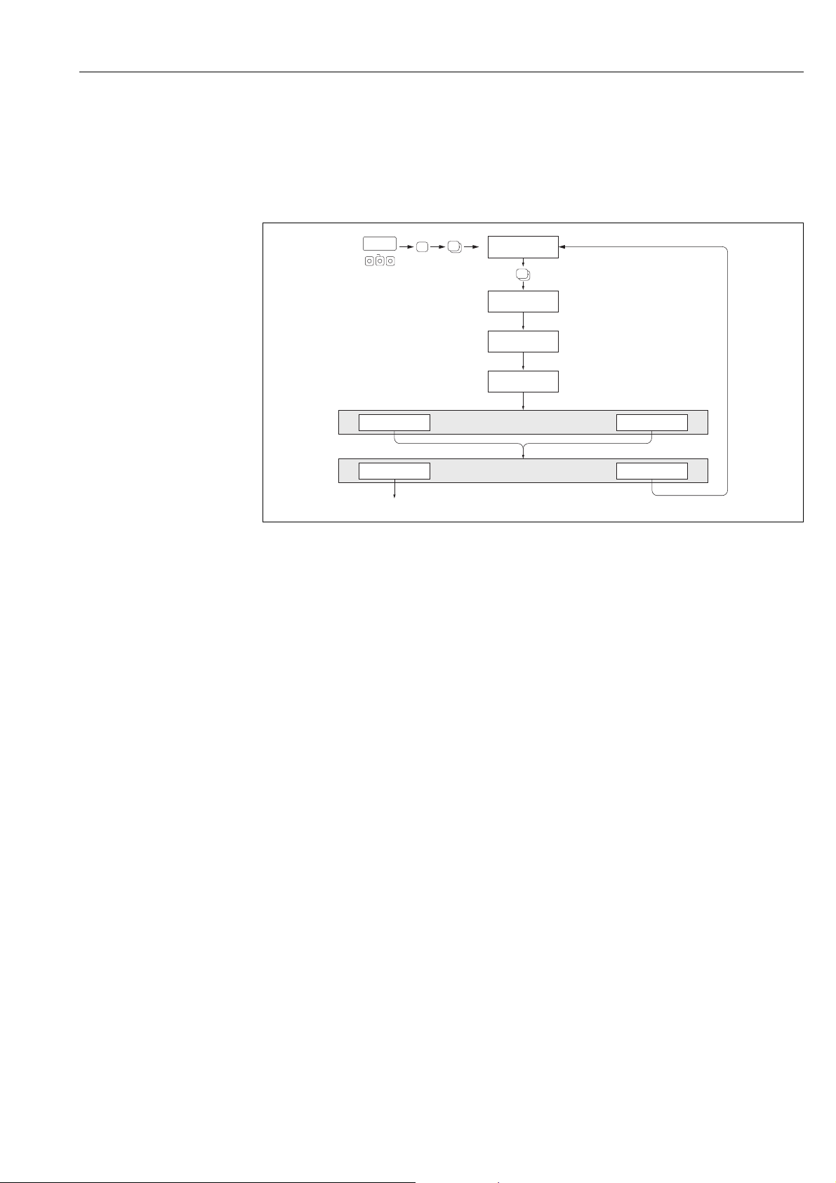
Proline t-mass 65 PROFIBUS DP/PA Commissioning
+
+
E
Esc
E
+
-
XXX.XXX.XX
+
E
HOME
POSITION
Setup
Communication
Quick Setup
Off Set unitUnit to bus
QS Commission NoOther Quick Setup?
Fieldbus Address
Selection
GSD
QS Commission
6.3.6 Quick Setup "Communication"
To establish cyclic data transfer, various arrangements between the PROFIBUS Master (class 1)
and the slave are required which have to be taken into consideration when configuring various
functions. These functions can be configured quickly and easily by means of the Communication
Quick Setup.
A0005459-EN
Fig. 36: Quick Setup Communication
QUICK SETUP - COMMUNICATION
Use the O or S key at the prompt "QS-COMMUNICATION NO" and the device access code
entry appears. Enter the device access code "65" and press F; programming is enabled.
The prompt "QS-COMMUNICATION NO" appears. Use the O or S key to change "NO" to "YES"
and press F.
FIELDBUS ADDRESS
Use the O or S key to enter the device address (1 to 126) and continue with F.
SELECTION GSD
Use the O or S key to select the operating mode (GSD file) which should be used for cyclic
communication with the PROFIBUS Master (class 1) and continue with F.
• MANUFACT. SPEC. (factory setting): The measuring device is operated with complete device
functionality.
• PROFILE-GSD The measuring device is operated in the PROFIBUS Profile mode.
!
Note!
For PROFIBUS network configuration, make sure that the right device master file (GSD file) of the
measuring device is used for the selected operating mode. ä 61
UNIT TO BUS
If this function is executed, the measured variables (AI modules) transmitted cyclically are
transmitted to the PROFIBUS Master (class 1) with the system unit configured in the
measuring device.
Endress+Hauser 57
Other Quick Setup?
To execute the Quick Setup Commission or back to the Quick Setup function group.
Page 58
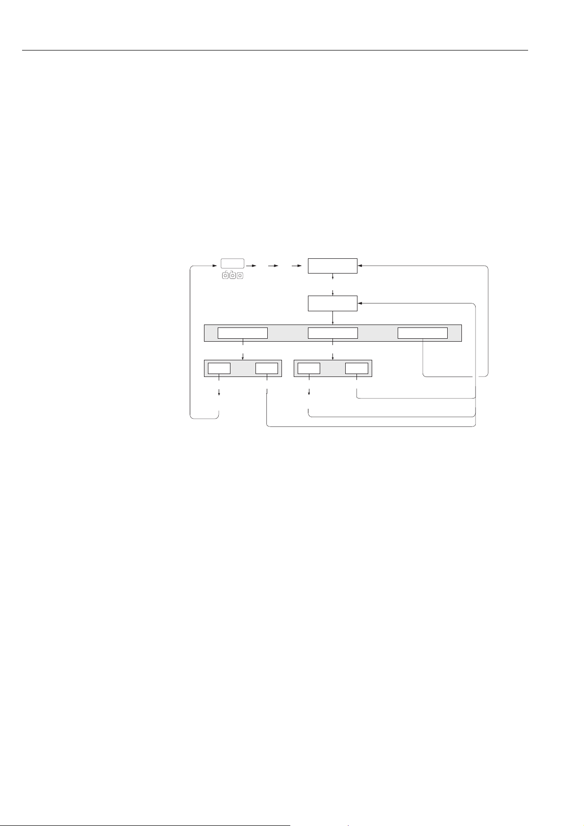
Commissioning Proline t-mass 65 PROFIBUS DP/PA
F
Esc
E
+
-
XXX.XXX.XX
F
F
F
F
F
F
P
P
P
P
N
O
T-DAT
SAVE/LOAD
Quick Setup
HOME
POSITION
LOAD
YES NO
CANCELSAVE
YES NO
Restart of the
measuring device
Input is
saved
6.3.7 Data backup/transmission
Using the T-DAT SAVE/LOAD function, you can transfer data (device parameters and settings)
between the T-DAT (exchangeable memory) and the EEPROM (device storage unit).
This is required in the following instances:
• Creating a backup: current data are transferred from an EEPROM to the T-DAT.
• Replacing a transmitter: current data are copied from an EEPROM to the T-DAT and then
transferred to the EEPROM of the new transmitter.
• Duplicating data: current data are copied from an EEPROM to the T-DAT and then transferred to
EEPROMs of identical measuring points.
!
Note!
For information on installing and removing the T-DAT ä 99
a0001221-en
Fig. 37: Data backup/transmission with T-DAT SAVE/LOAD function
Information on the LOAD and SAVE options available
LOAD:
Data are transferred from the T-DAT to the EEPROM.
!
Note!
• Any settings already saved on the EEPROM are deleted.
• This option is only available, if the T-DAT contains valid data.
• This option can only be executed if the software version of the T-DAT is the same or newer than
that of the EEPROM. Otherwise, the error message "TRANSM. SW-DAT" appears after restarting
and the LOAD function is then no longer available.
SAVE:
Data are transferred from the EEPROM to the T-DAT
58 Endress+Hauser
Page 59

Proline t-mass 65 PROFIBUS DP/PA Commissioning
6.4 Commissioning the PROFIBUS interface
!
Note!
• All functions required for commissioning are described in detail in the "Description of Device
Functions" manual which is a separate part of this Operating Manual.
• A code (factory setting: 65) must be entered to change device functions, numerical values or
factory settings ä 39.
6.4.1 PROFIBUS DP/PA commissioning
The following steps must be carried out in the sequence specified:
1. Check the hardware write protection:
The WRITE PROTECT parameter indicates whether it is possible to write to the device
parameters via PROFIBUS (acyclic data transmission, e.g. via operating program "FieldCare").
Note!
!
This check is not needed if operating via the local display.
COMMUNICATION WRITE PROTECT Display of one of the following options:
– OFF (factory setting) = write access via PROFIBUS possible
– ON = write access via PROFIBUS not possible
Deactivate the write protection if necessary:
PROFIBUS DP ä 43, PROFIBUS PA ä 46
2. Enter the tag name (optional):
COMMUNICATION TAG NAME
3. Configuring the fieldbus address:
• Software addressing using the local display or operating program:
COMMUNICATION FIELDBUS ADDRESS
• Hardware addressing via miniature switches
PROFIBUS DP ä 44, PROFIBUS PA ä 47
4. Select the system unit:
a. Determine the units by means of the system units group:
SYSTEM UNITS UNIT MASS FLOW / UNIT CORR. VOLUME FLOW/ UNIT…
b. In the function UNIT TO BUS, select the option SET UNITS, so that the measured variables
transmitted cyclically to the PROFIBUS Master (class 1) are transmitted with the system
units set in the measuring device: COMMUNICATION UNIT TO BUS
Note!
!
– The configuration of the system units for the totalizer is described separately see step 6.
– If the system unit of a measured variable is changed by means of the local operation or an
operating program, this initially does not have any effect on the unit that is used to transmit
the measured variable to the PROFIBUS Master (class 1). Changed system units of the
measured variables are not transmitted to the PROFIBUS Master (class 1) until the SET
UNITS option is activated in the function COMMUNICATION UNIT TO BUS.
Endress+Hauser 59
Page 60
Commissioning Proline t-mass 65 PROFIBUS DP/PA
5. Configuration of the Analog Input function blocks 1 to 3:
The measuring device has three Analog Input function block (AI modules), through which the
various measured variables can be cyclically transmitted to the PROFIBUS Master (class 1).
The assignment of a measured variable to the Analog Input function block is shown below
using the example of Analog Input function block 1 (AI module, slot 1).
Using the CHANNEL function, you can determine the measured variable (e.g. mass flow) to
be cyclically transmitted to the PROFIBUS Master (class 1):
a. Select COMMUNICATION BLOCK SELECTION
b. Select the option AI1 - OUT VALUE
c. Select the function CHANNEL
d. Select the option MASS FLOW
Possible setting
Measured variable ID for CHANNEL function
MASS FLOW (factory setting AI function block 1) 277
CORR. VOLUME FLOW (factory setting AI function block 2) 398
TEMPERATURE (factory setting AI function block 3) 285
Note!
!
If, when the PROFIBUS network configuration, the module "AI" was integrated in slot 1, 2 or 3, the measured
variable selected in the CHANNEL function is transmitted cyclically to the PROFIBUS Master (class 1) for the
respective Analog Input function block 1 to 3 (PROFIBUS DP ä 66, PROFIBUS PA ä 75).
6. Configuration of totalizers 1 to 2:
The measuring device has two totalizers. The following example describes the configuration of
the totalizer using totalizer 1 as an example.
Using the CHANNEL function, you can determine the measured variable (e.g. totalized mass
flow) to be cyclically transmitted to the PROFIBUS Master (class 1) as a totalizer value:
a. Select TOTALIZER SELECT TOTALIZER
b. Select the option TOTALIZER 1
c. Go to the function CHANNEL
d. Select the option MASS FLOW
Possible setting
Totalizer value / measured variable ID for CHANNEL function
MASS FLOW (factory setting totalizer 1 to 2) 277
CORR. VOLUME FLOW 398
OFF 0
Note!
!
If, when the PROFIBUS network configuration, the module or the function "TOTAL" was integrated in slot 4 or 5,
the measured variable selected in the CHANNEL function is transmitted cyclically to the PROFIBUS Master
(class 1) for the respective totalizer 1 to 2 (PROFIBUS DP ä 66, PROFIBUS PA ä 75).
• Enter the desired unit for the totalizer: TOTALIZER UNIT TOTALIZER
• Configure totalizer status (e.g. totalize): TOTALIZER SET TOTALIZER Option: TOTALIZE
• Set the totalizer mode: TOTALIZER MODE TOTALIZER: Select one of the following options:
– BALANCE (factory setting): calculates the positive and negative flow portions.
– POSITIVE: calculates the positive flow portions.
– NEGATIVE: calculates the positive flow portions.
– HOLD VALUE: The totalizer remains at the last value.
Note!
!
The device can’t calculate negative flow portions.
60 Endress+Hauser
Page 61

Proline t-mass 65 PROFIBUS DP/PA Commissioning
7. Select the operating mode:
Select the operating mode (GSD file) which should be used for cyclic data transmission with
the PROFIBUS Master.
COMMUNICATION SELECTION GSD Selection of one of the following options:
– MANUFACT. SPEC. (factory setting): the complete device functionality is available.
– PROFILE-GSD: The device is operated in the PROFIBUS Profile mode.
Note!
!
For PROFIBUS network configuration, make sure that the right device master file (GSD file) of
the measuring device is used for the selected operating mode ä 61
8. Configuration of cyclic data transmission in the PROFIBUS master:
A detailed description of the cyclic data transmission is contained on
PROFIBUS DP ä 64
PROFIBUS PA ä 73
6.5 PROFIBUS DP/PA system integration
6.5.1 Device master file (GSD file)
For PROFIBUS network configuration, the device master file (GSD file) is needed for every bus
participant (PROFIBUS slave). The GSD file contains a description of the properties of a PROFIBUS
device, such as supported data transmission rate and number of input and output data.
Before configuration takes place, a decision should be made as to which GSD file should be used to
operate the measuring device in the PROFIBUS DP Master (class 1) system.
The measuring device supports the following GSD files:
• t-mass GSD file (manufacturer-specific GSD file, complete device functionality)
• PROFIBUS Profile GSD file:
Below you will find a detailed description of the GSD files supported.
t-mass GSD file (manufacturer-specific GSD file, complete device functionality)
Use this GSD file to access the complete functionality of the measuring device. In this way, devicespecific measured variables and functions are thus completely available in the PROFIBUS master
system. An overview of the modules available (input and output data) is contained on ä 64
GSD file with standard or extended format
The GSD file with either the standard or the extended format must be used depending on the
PROFIBUS Master used. When installing the GSD file, the GSD file with the extended format
(EH3x15xx.gsd) should always be used first.
However, if the installation or the configuration of the measuring device fails with this format, then
use the standard GSD (EH3_15xx.gsd). This differentiation is the result of different implementation
of the GSD formats in the master systems. Note the specifications of the PROFIBUS Master.
Endress+Hauser 61
Page 62
Commissioning Proline t-mass 65 PROFIBUS DP/PA
Name of the t-mass GSD file
ID No. GSD file Bitmaps
PROFIBUS DP 1545 (Hex) Extended Format (recommended):
Standard Format:
PROFIBUS PA 1550 (Hex) Extended Format (recommended):
Standard Format:
EH3x1545.gsd
EH3_1545.gsd
EH3x1550.gsd
EH3_1550.gsd
EH_1545_d.bmp/.dib
EH_1545_n.bmp/.dib
EH_1545_s.bmp/.dib
EH_1550_d.bmp/.dib
EH_1550_n.bmp/.dib
EH_1550_s.bmp/.dib
Source
• Internet (Endress+Hauser) www.endress.com ( Download Software Device Drivers)
• CD-ROM with all GSD files for Endress+Hauser devices Order No.: 56003894
Contents of the download file from the Internet and the CD-ROM
• All Endress+Hauser GSD files (standard and extended format)
• Endress+Hauser bitmap files
• Useful information relating to the devices
PROFIBUS Profile GSD file:
The function scope of the profile GSD file is defined by the PROFIBUS Profile Specification 3.0.
The function scope is restricted compared to the manufacturer-specific GSD file (complete device
functionality). However, similar devices from different manufacturers can be interchanged with the
profile GSD file without the need to reconfigure (interchangeability).
The following modules are supported with the Profile GSD file:
• "AI Flow" module Analog Input function block 1/output variable: mass flow
• "Totalizer" module Totalizer function block 1/output variable: totalized mass flow
Name of the PROFIBUS Profile GSD file
ID No. Profile GSD file
PROFIBUS DP 9740 (Hex) PA039740.gsd
PROFIBUS PA 9740 (Hex) PA039740.gsd
Source
Internet (GSD library of the PROFIBUS User Organization) www.PROFIBUS.com
62 Endress+Hauser
Page 63

Proline t-mass 65 PROFIBUS DP/PA Commissioning
6.5.2 Example for selecting the GSD file
Before configuration takes place, a decision should be made as to which GSD file should be used to
configure the measuring device in the PROFIBUS master system. The following example describes
the use of the t-mass 65 GSD file (complete functionality) for PROFIBUS PA:
Select the t-mass 65 GSD file in the measuring device by means of the SELECTION GSD function.
COMMUNICATION SELECTION GSD Select: MANUFACT. SPEC.
1. Before configuring the network, load the t-mass 65 GSD file into the configuration system/
master system.
Note!
!
When installing the GSD file, always first use the GSD file with the extended format
(EH3x1545.gsd). However, if the installation or the configuration of the device fails with this
format, then use the standard GSD (EH3_1545.gsd).
Example for the configuration software Siemens STEP 7 of the Siemens PLC family
S7-300/400:
Use the t-mass 65 GSD file with the extended format (EH3x1545.gsd).
Copy the file to the subdirectory …\ siemens \ step7 \ s7data \ gsd.
The bitmap files also belong to the GSD files. These bitmap files are used to display the
measuring points in image form. The bitmap files must be saved to the directory "…\ siemens
\ step7 \ s7data \ nsbmp".
If you are using configuration software other than that referred to above, ask your PROFIBUS
master system manufacturer which directory you should use.
2. t-mass 65 is a modular PROFIBUS slave, i.e. the desired module configuration (input and
output data) must be performed in the next step for t-mass 65. This can be done directly by
means of the configuration software.
A detailed description of the modules supported by the measuring device can be found on
ä 65
6.5.3 Maximum number of writes
If a non-volatile device parameter is modified via the cyclic or acyclic data transmission, this
change is saved in the EEPROM of the measuring device. The number of writes to the EEPROM
is technically restricted to a maximum of 1 million. Attention must be paid to this limit since, if
exceeded, it results in data loss and measuring device failure. For this reason, avoid constantly
writing non-volatile device parameters via the PROFIBUS!
Endress+Hauser 63
Page 64
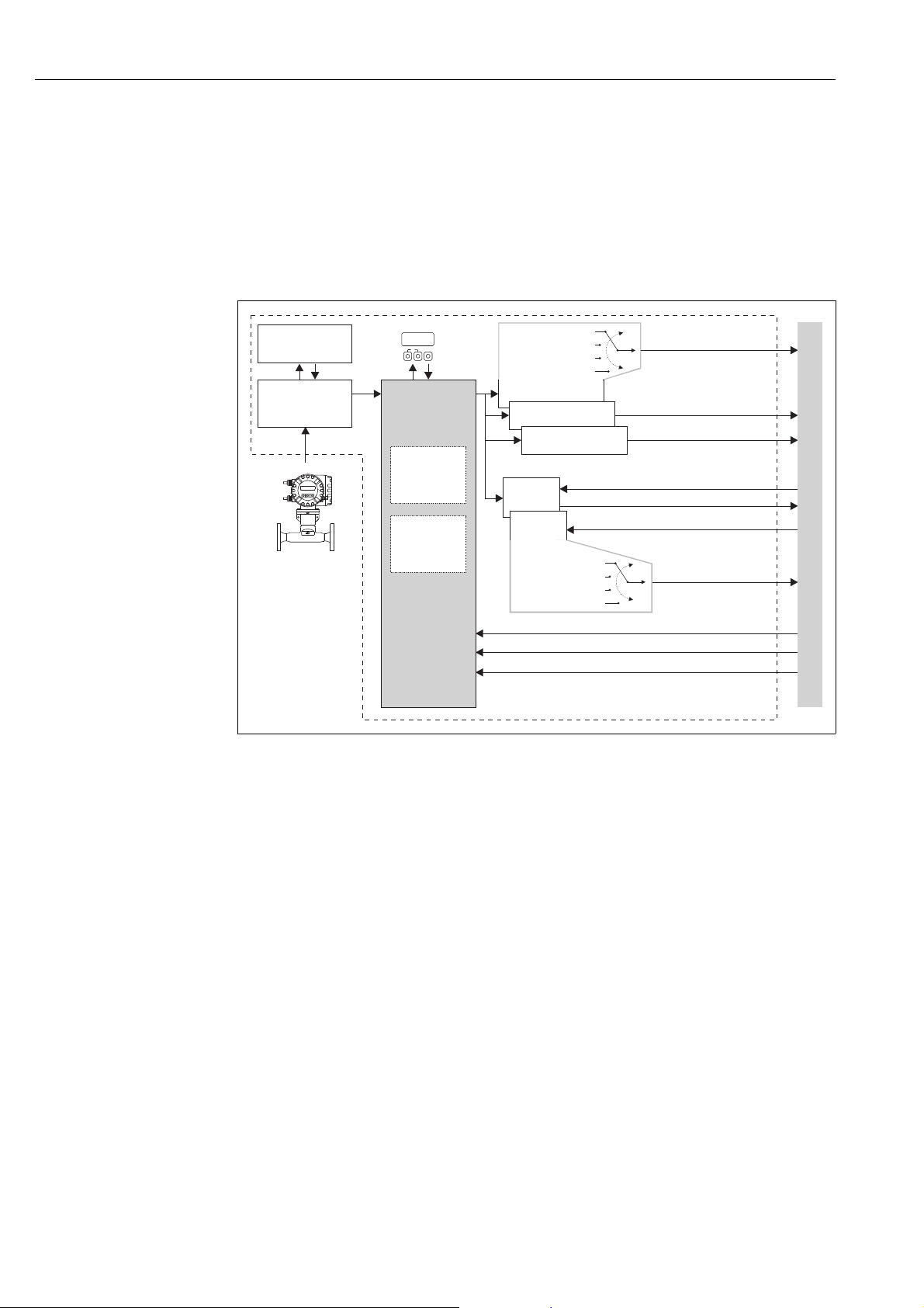
Commissioning Proline t-mass 65 PROFIBUS DP/PA
Esc
E
+
-
XXX.XXX.XX
Measured variable 1
Measured variable 2
Measured variable 3
Measured variable …
Measured variable 1
Measured variable 2
Measured variable 3
Measured variable …
Analog Input 1
Output value AI
Output value AI
Analog Input 2
Signal
processing
PROFIBUS
PROFILE
Parameter
Manufacturer
specific
Parameter
Control (CONTROL_BLOCK)
Display value (DISPLAY_VALUE)
Transducer
block
Totalizer 2
Out value TOTAL
Local
Display
Out value TOTAL
Totalizer 1
Process pressure (PRESSURE_VALUE)
PROFIBUS DP
Physical
Block
Configuration SETTOT, MODETOT
Configuration SETTOT, MODETOT
Analog Input 3
Output value AI
6.6 PROFIBUS DP cyclic data transmission
Below is a description of the cyclic data transmission when using the t-mass GSD file (complete
device functionality).
6.6.1 Block model
The block model illustrated shows which input and output data the measuring device provides for
cyclic data transmission via PROFIBUS DP.
a0005482-en
Fig. 38: Block model for t-mass PROFIBUS DP Profile 3.0
64 Endress+Hauser
Page 65
Proline t-mass 65 PROFIBUS DP/PA Commissioning
6.6.2 Modules for cyclic data transmission
The measuring device is a so-called modular PROFIBUS slave. In contrast to a compact slave, the
structure of a modular slave is variable - it consists of several individual modules. In the GSD file,
the individual modules (input and output data) are described with their individual properties. The
modules are permanently assigned to the slots, i.e. the sequence or arrangement of the modules
must be observed when configuring the modules (see following table). Gaps between configured
modules have to be assigned the EMPTY_MODULE module.
To optimize the data throughput rate of the PROFIBUS network, it is recommended to only
configure modules that are processed in the PROFIBUS master system.
It is essential to adhere to the following sequence/assignment when configuring the modules in the
PROFIBUS master system:
Slot sequence Module Description
1AI
2AI
3AI
TOTAL or
4
5
6 DISPLAY_VALUE Value for local display
7 CONTROL_BLOCK Control of device functions
8 PRESSURE_VALUE Process pressure
SETTOT_TOTAL or
SETTOT_MODETOT_TOTAL
TOTAL or
SETTOT_TOTAL or
SETTOT_MODETOT_TOTAL
Analog Input function block 1
Output variable Mass flow (factory setting)
Analog Input function block 2
Output variable Corrected volume flow (factory setting)
Analog Input function block 3
Output variable Temperature (factory setting)
Totalizer function block 1
TOTAL output variable = totalized mass flow (factory setting)
SETTOT totalizer control
MODETOT totalizer configuration
Totalizer function block 2
TOTAL output variable = totalized mass flow (factory setting)
SETTOT totalizer control
MODETOT totalizer configuration
!
Note!
• The assignment of the measured variables for the Analog Input function blocks (1 to 3) and the
totalizer function blocks (1 to 2) can be changed by means of the CHANNEL function.
A detailed description of the individual modules is contained in the following section.
• The device has to be reset once a new configuration has been loaded to the automation system.
This can be effected as follows:
– By means of the local display
– By means of an operating program (e.g. FieldCare)
– By switching the supply voltage off and on again.
Endress+Hauser 65
Page 66
Commissioning Proline t-mass 65 PROFIBUS DP/PA
6.6.3 Description of the modules
AI (Analog Input) module
The AI module (slots 1 to 3) cyclically transmits the corresponding measured variable, including
the status, to the PROFIBUS Master (class 1). The measured variable is represented in the first
four bytes in the form of floating point numbers in accordance with the IEEE 754 standard.
The fifth byte contains standardized status information corresponding to the measured variable.
Further information on the device status ä 90.
Input data
Byte 1 Byte 2 Byte 3 Byte 4 Byte 5
measured variable (IEEE 754 floating point number) Status
Assignment of the measured variables to the AI module
The AI module can transmit different measured variables to the PROFIBUS Master (class 1).
The measured variables are assigned to the Analog Input function blocks 1 to 3 by means of the
local display or with the aid of an operating program (e.g. FieldCare) in the CHANNEL function:
• COMMUNICATION BLOCK SELECTION: Selection of an Analog Input function block
• COMMUNICATION CHANNEL: Selection of a measured variable
Possible settings
Measured variable ID for CHANNEL function
MASS FLOW 277
CORR. VOLUME FLOW 398
TEMPERATURE 285
Factory setting
Module Analog Input
function block
AI (slot 1) 1 MASS FLOW 277
AI (slot 2) 2 CORR. VOLUME FLOW 398
AI (slot 3) 3 TEMPERATURE 285
Measured variable ID for CHANNEL function
TOTAL module
The measuring device has three totalizer function blocks. The totalizer values can be cyclically
transmitted to the PROFIBUS Master (class 1) via the TOTAL module (slots 4 to 5). The totalizer
value is represented in the first four bytes in the form of a floating point number in accordance with
the IEEE 754 standard. The fifth byte contains standardized status information corresponding to the
totalizer value. Further information on the device status ä 90.
Input data
Byte 1 Byte 2 Byte 3 Byte 4 Byte 5
Totalizer value (IEEE 754 floating point number) Status
66 Endress+Hauser
Page 67
Proline t-mass 65 PROFIBUS DP/PA Commissioning
Assignment of the measured variables to the TOTAL module
The TOTAL module can transmit different totalizer variables to the PROFIBUS Master (class 1).
The measured variables are assigned to the totalizer function blocks 1 to 2 by means of the local
display or with the aid of an operating program (e.g. FieldCare) in the CHANNEL function:
• TOTALIZER SELECT TOTALIZER: Selection of a totalizer
• COMMUNICATION CHANNEL: Selection of measured variable
Possible settings
Totalizer value/measured variable ID for CHANNEL function
MASS FLOW 277
CORR. VOLUME FLOW 398
OFF 0
Factory setting
!
Module Totalizer
function block
TOTAL (slot 4) 1 MASS FLOW 277
TOTAL (slot 5) 2 MASS FLOW 277
Totalizer value/
Measured variable
ID for CHANNEL function
SETTOT_TOTAL module
The module combination SETTOT_TOTAL (slots 4 to 5) consists of the functions SETTOT and
TOTAL. With this module combination:
• The totalizer can be controlled via the PROFIBUS Master (SETTOT).
• The totalizer value, is transmitted, including the status (TOTAL).
SETTOT function
In the SETTOT function, the totalizer can be controlled via control variables.
The following control variables are supported:
• 0 = Totalize (factory setting)
• 1 = Reset totalizer (the totalizer value is reset to 0)
• 2 = Accept totalizer preset
Note!
After the totalizer value has been reset to 0 or set to the preset value, the totalizing continues
automatically. The control variable does not have to be changed to 0 again to restart totalizing.
Stopping totalizing is controlled in the SETTOT_MODETOT_TOTAL module via the MODETOT
function. ä 68
TOTAL function
For a description of the TOTAL function, refer to TOTAL module ä 66
Data structure of the SETTOT_TOTAL module combination
Output data Input data
SETTOT TOTAL
Byte 1 Byte 1 Byte 2 Byte 3 Byte 4 Byte 5
Control Totalizer value (IEEE 754 floating point number) Status
Endress+Hauser 67
Page 68
Commissioning Proline t-mass 65 PROFIBUS DP/PA
SETTOT_MODETOT_TOTAL module
The module combination SETTOT_MODETOT_TOTAL (slots 4 to 5) consists of the functions
SETTOT, MODETOT and TOTAL.
With this module combination:
• The totalizer can be controlled via the PROFIBUS Master (SETTOT).
• The totalizer can be configured via the PROFIBUS Master (MODETOT).
• The totalizer value, is transmitted, including the status (TOTAL).
SETTOT function
For a description of the SETTOT function, refer to SETTOT_TOTAL module ä 67
MODETOT function
In the MODETOT function, the totalizer can be configured via control variables.
The following settings are possible:
• 0 = Balance (factory setting), calculates the positive and negative flow portions
• 1 = calculates the positive flow portions
• 2 = calculates the negative flow portions
• 3 = Totalizing is stopped
!
Note!
The device can’t calculate negative flow portions.
TOTAL function
For a description of the TOTAL function, refer to TOTAL module ä 66
Data structure of the SETTOT_MODETOT_TOTAL module combination
Output data Input data
SETTOT MODETOT TOTAL
Byte 1 Byte 2 Byte 1 Byte 2 Byte 3 Byte 4 Byte 5
Control Configuration Totalizer value (IEEE 754 floating point number) Status
Example of using the SETTOT_MODETOT_TOTAL module
If the SETTOT function is set to 1 (= reset the totalizer), the value for the aggregated total is reset
to 0. If the aggregated total of the totalizer should constantly retain the value 0, the MODETOT
function must first be set to 3 (= totalizing is stopped) and then the SETTOT function must be set
to 1 (= reset the totalizer).
68 Endress+Hauser
Page 69
Proline t-mass 65 PROFIBUS DP/PA Commissioning
DISPLAY_VALUE module
Any value (IEEE 754 floating point number), including status, can be cyclically transmitted via the
PROFIBUS Master (class 1) directly to the local display using the DISPLAY_VALUE module (slot 6).
Display value assignment to line 1 or line 2 can be configured via the local display itself or an
operating program (e.g. FieldCare).
Output data
Byte 1 Byte 2 Byte 3 Byte 4 Byte 5
Display value (IEEE 754 floating point number) Status
Status
The status is not evaluated by the device.
CONTROL_BLOCK module
By means of the CONTROL_BLOCK module (slot 7), the measuring device is able to process devicespecific control variables from the PROFIBUS Master (class 1) in cyclic data transmission (e.g.
switching on positive zero return).
!
Supported control variables of the CONTROL_BLOCK module
The following device-specific control variables can be activated by changing the output
byte from 0 x:
Module Control variables
0 2: Positive zero return ON
CONTROL_BLOCK
0 3: Positive zero return OFF
0 4: Carrying out the zero point adjustment
0 24: Run UNIT TO BUS function
Note!
The control (e.g. switching on positive zero return) is executed by cyclic data transmission if the
output byte switches from "0" to the bit pattern in question. The output byte must always switch
from "0". A switchback to "0" does not have any effect.
Example (change the output byte)
From To Result
0 2 Positive zero return is switched on.
2 0 No effect.
0 3 Positive zero return is switched off.
3 2 No effect.
Output data
Byte 1
Control
Endress+Hauser 69
Page 70
Commissioning Proline t-mass 65 PROFIBUS DP/PA
PRESSURE_VALUE module
The process pressure value (IEEE 754 floating point number), including status, can be cyclically
transmitted via the PROFIBUS Master (class 1) directly to the measuring device using the
PRESSURE_VALUE module (slot 8).
The process pressure value is used to compensate for large variations in process pressure, e.g.
Ammonid gas applications. The unit pressure selected in the measuring device is used.
More details to the PROCESS PRESSURE function are contained in the "Description of Device
Functions" manual, BA00114D/06/… .
Caution!
"
The process pressure is a non-volatile device parameter. A constant overwriting of this
non-volatile device parameter via the PROFIBUS is to be avoided ä 63.
Output data
Byte 1 Byte 2 Byte 3 Byte 4 Byte 5
Process pressure (IEEE 754 floating point number) Status
!
Note!
The status is not evaluated by the device.
EMPTY_MODULE module
The measuring device is a so-called modular PROFIBUS slave. In contrast to a compact slave, the
structure of a modular slave is variable - it consists of several individual modules. In the GSD file,
the individual modules are described with their individual properties. The modules are permanently
assigned to the slots, i.e. the sequence or arrangement of the modules must be observed when
configuring the modules. Gaps between configured modules have to be assigned to the
EMPTY_MODULE module. For a more detailed description, see ä 65.
70 Endress+Hauser
Page 71
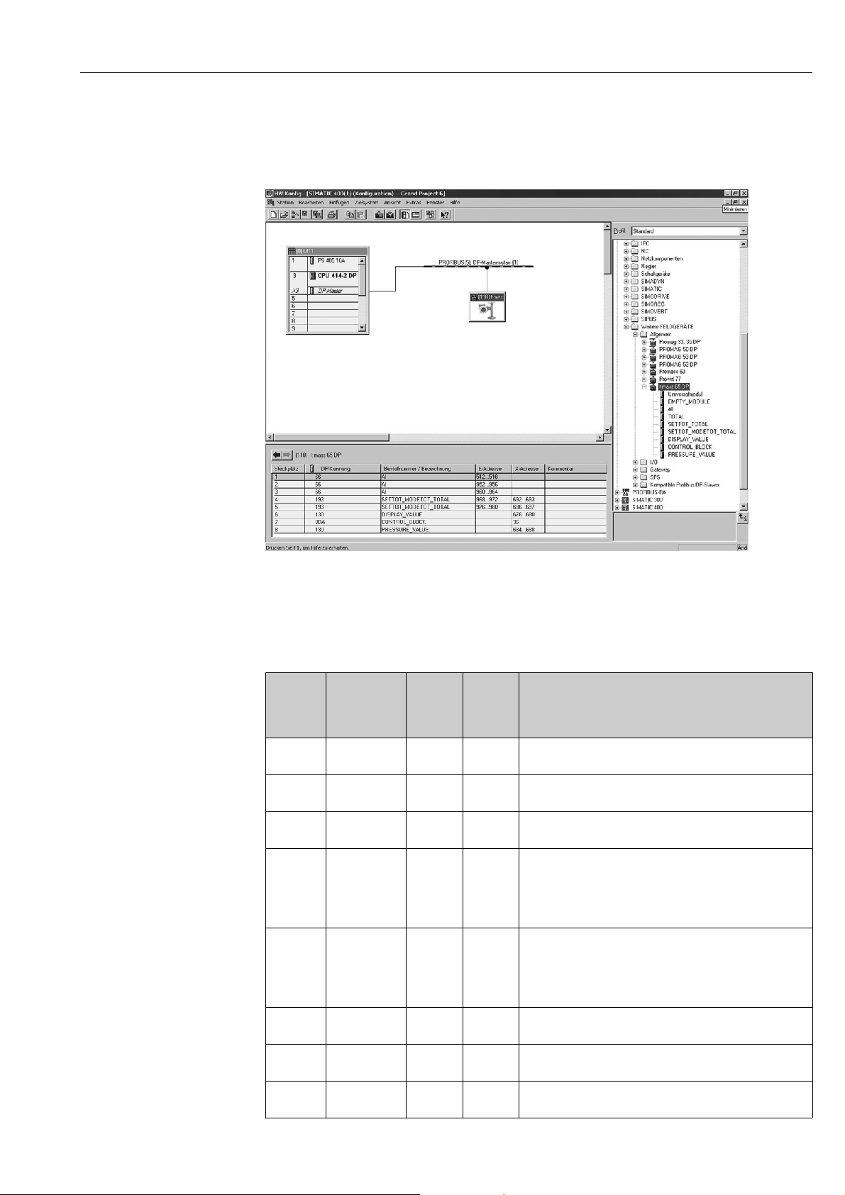
Proline t-mass 65 PROFIBUS DP/PA Commissioning
6.6.4 Configuration examples with Simatic S7 HW-Konfig
Example 1
Fig. 39: Complete configuration using the t-mass 65 GSD file
It is essential to adhere to the following sequence when configuring the modules in the
PROFIBUS Master (class 1):
Byte
Slot
sequence
1AI5-
2AI5-
3AI5-
4
5
Module
SETTOT
_MODETOT
_TOTAL
SETTOT
_MODETOT
_TOTAL
length
input
data
52
52
Byte
length
output
data
Description
Analog Input function block 1
Output variable mass flow (factory setting)
Analog Input function block 1
Output variable corr. volume flow (factory setting)
Analog Input function block 1
Output variable temperature (factory setting)
Totalizer function block 1
TOTAL output variable = totalized mass flow (factory setting)
SETTOT totalizer control
MODETOT totalizer configuration
Totalizer function block 2
TOTAL output variable = totalized mass flow (factory setting)
SETTOT totalizer control
MODETOT totalizer configuration
a0005497
6
7
8
DISPLAY
_VALUE
CONTROL
_BLOCK
PRESSURE
_VALUE
-5
-1
-5
Value for local display
Control of device functions
Process pressure
Endress+Hauser 71
Page 72
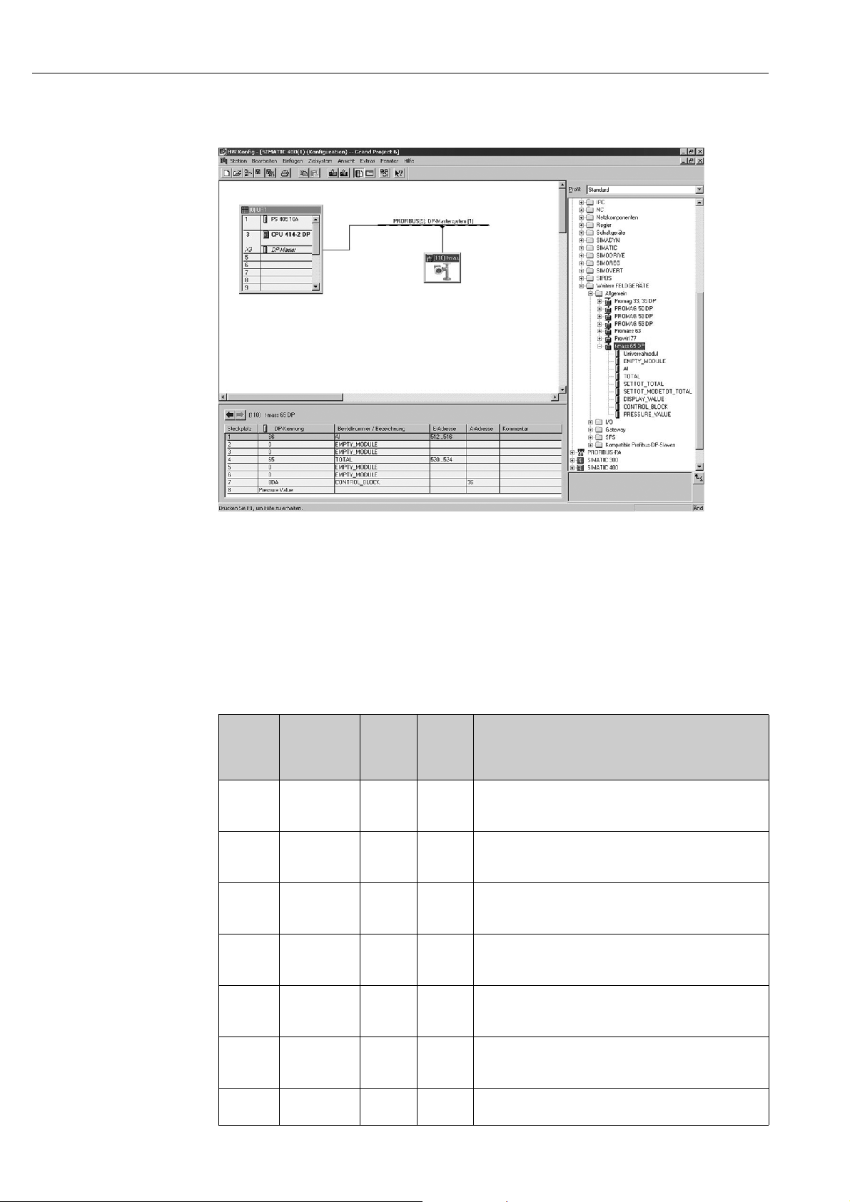
Commissioning Proline t-mass 65 PROFIBUS DP/PA
Example 2
a0005498
Fig. 40: In this example, modules that are not needed are replaced by the module EMPTY_MODULE.
The t-mass 65 GSD file is used .
With this configuration, the Analog Input function block 1 (slot 1), the totalizer value TOTAL
(slot 4) and the cyclic control of device functions CONTROL_BLOCK (slot 7) are activated.
The mass flow (factory setting) is read out cyclically by the measuring device by means of Analog
Input function block 1. The totalizer is configured "without configuration". In other words, in this
example it only returns the totalizer value for the mass flow (factory setting) by means of the TOTAL
module and cannot be controlled by the PROFIBUS Master (class 1).
Byte
Slot
sequence
1AI5-
2
3
Module
EMPTY
_MODULE
EMPTY
_MODULE
length
input
data
--
--
Byte
length
output
data
Description
Analog Input function block 1
Output variable mass flow (factory setting)
Empty
Empty
4TOTAL5-
5
6
7
EMPTY
_MODULE
EMPTY
_MODULE
CONTROL
_BLOCK
--
--
-1
Totalizer function block 1
TOTAL output variable = totalized mass flow (factory setting)
Empty
Empty
Control of device functions
72 Endress+Hauser
Page 73
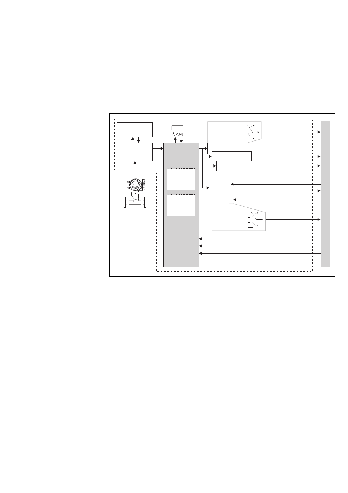
Proline t-mass 65 PROFIBUS DP/PA Commissioning
Esc
E
+
-
XXX.XXX.XX
Measured variable 1
Measured variable 2
Measured variable 3
Measured variable …
Measured variable 1
Measured variable 2
Measured variable 3
Measured variable …
Analog Input 1
Output value AI
Output value AI
Analog Input 2
Signal
processing
PROFIBUS
PROFILE
Parameter
Manufacturer
specific
Parameter
Control (CONTROL_BLOCK)
Display value (DISPLAY_VALUE)
Transducer
block
Totalizer 2
Out value TOTAL
Local
Display
Out value TOTAL
Totalizer 1
Process pressure (PRESSURE_VALUE)
PROFIBUS PA
Physical
Block
Configuration SETTOT, MODETOT
Configuration SETTOT, MODETOT
Analog Input 3
Output value AI
6.7 PROFIBUS PA cyclic data transmission
Below is a description of the cyclic data transmission when using the t-mass GSD file (complete
device functionality).
6.7.1 Block model
The block model illustrated shows which input and output data the measuring device provides for
cyclic data transmission via PROFIBUS PA.
a0014661-en
Fig. 41: Block model for t-mass PROFIBUS PA Profile 3.0
Endress+Hauser 73
Page 74
Commissioning Proline t-mass 65 PROFIBUS DP/PA
6.7.2 Modules for cyclic data transmission
The measuring device is a so-called modular PROFIBUS slave. In contrast to a compact slave, the
structure of a modular slave is variable - it consists of several individual modules. In the GSD file,
the individual modules (input and output data) are described with their individual properties. The
modules are permanently assigned to the slots, i.e. the sequence or arrangement of the modules
must be observed when configuring the modules (see following table). Gaps between configured
modules have to be assigned the EMPTY_MODULE module.
To optimize the data throughput rate of the PROFIBUS network, it is recommended to only
configure modules that are processed in the PROFIBUS master system.
It is essential to adhere to the following sequence/assignment when configuring the modules in the
PROFIBUS master system:
Slot sequence Module Description
1AI
2AI
3AI
TOTAL or
4
5
6 DISPLAY_VALUE Value for local display
7 CONTROL_BLOCK Control of device functions
8 PRESSURE_VALUE Process pressure
SETTOT_TOTAL or
SETTOT_MODETOT_TOTAL
TOTAL or
SETTOT_TOTAL or
SETTOT_MODETOT_TOTAL
Analog Input function block 1
Output variable Mass flow (factory setting)
Analog Input function block 2
Output variable Corrected volume flow (factory setting)
Analog Input function block 3
Output variable Temperature (factory setting)
Totalizer function block 1
TOTAL output variable = totalized mass flow (factory setting)
SETTOT totalizer control
MODETOT totalizer configuration
Totalizer function block 2
TOTAL output variable = totalized mass flow (factory setting)
SETTOT totalizer control
MODETOT totalizer configuration
!
Note!
• The assignment of the measured variables for the Analog Input function blocks (1 to 3) and the
totalizer function blocks (1 to 2) can be changed by means of the CHANNEL function.
A detailed description of the individual modules is contained in the following section.
• The device has to be reset once a new configuration has been loaded to the automation system.
This can be effected as follows:
– By means of the local display
– By means of an operating program (e.g. FieldCare)
– By switching the supply voltage off and on again.
74 Endress+Hauser
Page 75
Proline t-mass 65 PROFIBUS DP/PA Commissioning
6.7.3 Description of the modules
AI (Analog Input) module
The AI module (slots 1 to 3) cyclically transmits the corresponding measured variable, including
the status, to the PROFIBUS Master (class 1). The measured variable is represented in the first
four bytes in the form of floating point numbers in accordance with the IEEE 754 standard.
The fifth byte contains standardized status information corresponding to the measured variable.
Further information on the device status ä 90.
Input data
Byte 1 Byte 2 Byte 3 Byte 4 Byte 5
measured variable (IEEE 754 floating point number) Status
Assignment of the measured variables to the AI module
The AI module can transmit different measured variables to the PROFIBUS Master (class 1).
The measured variables are assigned to the Analog Input function blocks 1 to 3 by means of the
local display or with the aid of an operating program (e.g. FieldCare) in the CHANNEL function:
• COMMUNICATION BLOCK SELECTION: Selection of an Analog Input function block
• COMMUNICATION CHANNEL: Selection of a measured variable
Possible settings
Measured variable ID for CHANNEL function
MASS FLOW 277
CORR. VOLUME FLOW 398
TEMPERATURE 285
Factory setting
Module Analog Input
function block
AI (slot 1) 1 MASS FLOW 277
AI (slot 2) 2 CORR. VOLUME FLOW 398
AI (slot 3) 3 TEMPERATURE 285
Measured variable ID for CHANNEL function
TOTAL module
The measuring device has three totalizer function blocks. The totalizer values can be cyclically
transmitted to the PROFIBUS Master (class 1) via the TOTAL module (slots 4 to 5). The totalizer
value is represented in the first four bytes in the form of a floating point number in accordance with
the IEEE 754 standard. The fifth byte contains standardized status information corresponding to the
totalizer value. Further information on the device status ä 90.
Input data
Byte 1 Byte 2 Byte 3 Byte 4 Byte 5
Totalizer value (IEEE 754 floating point number) Status
Endress+Hauser 75
Page 76
Commissioning Proline t-mass 65 PROFIBUS DP/PA
Assignment of the measured variables to the TOTAL module
The TOTAL module can transmit different totalizer variables to the PROFIBUS Master (class 1).
The measured variables are assigned to the totalizer function blocks 1 to 2 by means of the local
display or with the aid of an operating program (e.g. FieldCare) in the CHANNEL function:
• TOTALIZER SELECT TOTALIZER: Selection of a totalizer
• COMMUNICATION CHANNEL: Selection of measured variable
Possible settings
Totalizer value/measured variable ID for CHANNEL function
MASS FLOW 277
CORR. VOLUME FLOW 398
OFF 0
Factory setting
!
Module Totalizer
function block
TOTAL (slot 4) 1 MASS FLOW 277
TOTAL (slot 5) 2 MASS FLOW 277
Totalizer value/
Measured variable
ID for CHANNEL function
SETTOT_TOTAL module
The module combination SETTOT_TOTAL (slots 4 to 5) consists of the functions SETTOT and
TOTAL. With this module combination:
• The totalizer can be controlled via the PROFIBUS Master (SETTOT).
• The totalizer value, is transmitted, including the status (TOTAL).
SETTOT function
In the SETTOT function, the totalizer can be controlled via control variables.
The following control variables are supported:
• 0 = Totalize (factory setting)
• 1 = Reset totalizer (the totalizer value is reset to 0)
• 2 = Accept totalizer preset
Note!
After the totalizer value has been reset to 0 or set to the preset value, the totalizing continues
automatically. The control variable does not have to be changed to 0 again to restart totalizing.
Stopping totalizing is controlled in the SETTOT_MODETOT_TOTAL module via the MODETOT
function. ä 68
TOTAL function
For a description of the TOTAL function, refer to TOTAL module ä 66
Data structure of the SETTOT_TOTAL module combination
Output data Input data
SETTOT TOTAL
Byte 1 Byte 1 Byte 2 Byte 3 Byte 4 Byte 5
Control Totalizer value (IEEE 754 floating point number) Status
76 Endress+Hauser
Page 77
Proline t-mass 65 PROFIBUS DP/PA Commissioning
SETTOT_MODETOT_TOTAL module
The module combination SETTOT_MODETOT_TOTAL (slots 4 to 5) consists of the functions
SETTOT, MODETOT and TOTAL.
With this module combination:
• The totalizer can be controlled via the PROFIBUS Master (SETTOT).
• The totalizer can be configured via the PROFIBUS Master (MODETOT).
• The totalizer value, is transmitted, including the status (TOTAL).
SETTOT function
For a description of the SETTOT function, refer to SETTOT_TOTAL module ä 67
MODETOT function
In the MODETOT function, the totalizer can be configured via control variables.
The following settings are possible:
• 0 = Balance (factory setting), calculates the positive and negative flow portions
• 1 = calculates the positive flow portions
• 2 = calculates the negative flow portions
• 3 = Totalizing is stopped
!
Note!
The device can’t calculate negative flow portions.
TOTAL function
For a description of the TOTAL function, refer to TOTAL module ä 66
Data structure of the SETTOT_MODETOT_TOTAL module combination
Output data Input data
SETTOT MODETOT TOTAL
Byte 1 Byte 2 Byte 1 Byte 2 Byte 3 Byte 4 Byte 5
Control Configuration Totalizer value (IEEE 754 floating point number) Status
Example of using the SETTOT_MODETOT_TOTAL module
If the SETTOT function is set to 1 (= reset the totalizer), the value for the aggregated total is reset
to 0. If the aggregated total of the totalizer should constantly retain the value 0, the MODETOT
function must first be set to 3 (= totalizing is stopped) and then the SETTOT function must be set
to 1 (= reset the totalizer).
Endress+Hauser 77
Page 78
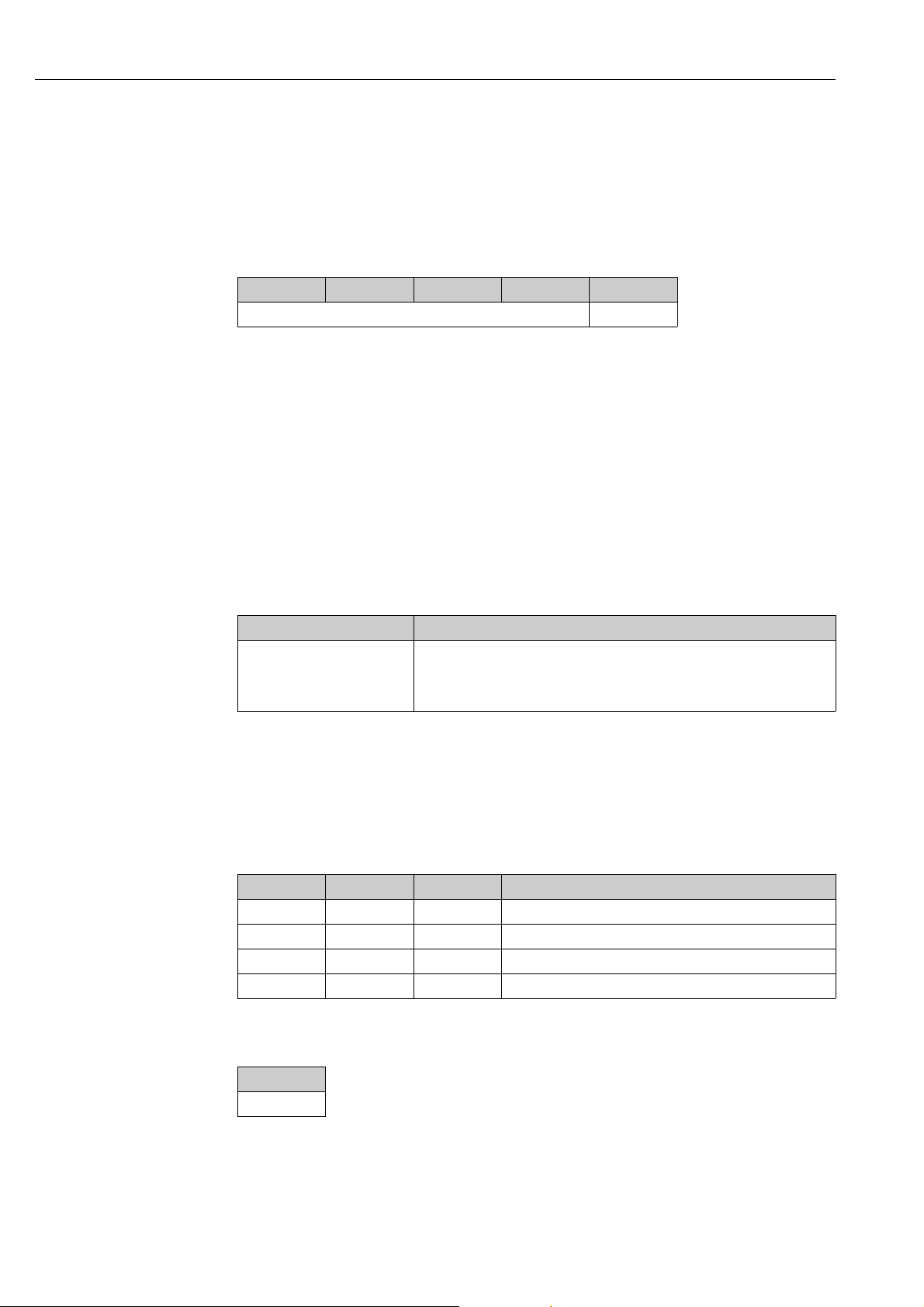
Commissioning Proline t-mass 65 PROFIBUS DP/PA
DISPLAY_VALUE module
Any value (IEEE 754 floating point number), including status, can be cyclically transmitted via the
PROFIBUS Master (class 1) directly to the local display using the DISPLAY_VALUE module (slot 6).
Display value assignment to line 1 or line 2 can be configured via the local display itself or an
operating program (e.g. FieldCare).
Output data
Byte 1 Byte 2 Byte 3 Byte 4 Byte 5
Display value (IEEE 754 floating point number) Status
Status
The status is not evaluated by the device.
CONTROL_BLOCK module
By means of the CONTROL_BLOCK module (slot 7), the measuring device is able to process devicespecific control variables from the PROFIBUS Master (class 1) in cyclic data transmission (e.g.
switching on positive zero return).
!
Supported control variables of the CONTROL_BLOCK module
The following device-specific control variables can be activated by changing the output
byte from 0 x:
Module Control variables
0 2: Positive zero return ON
CONTROL_BLOCK
0 3: Positive zero return OFF
0 4: Carrying out the zero point adjustment
0 24: Run UNIT TO BUS function
Note!
The control (e.g. switching on positive zero return) is executed by cyclic data transmission if the
output byte switches from "0" to the bit pattern in question. The output byte must always switch
from "0". A switchback to "0" does not have any effect.
Example (change the output byte)
From To Result
0 2 Positive zero return is switched on.
2 0No effect.
0 3 Positive zero return is switched off.
3 2No effect.
Output data
Byte 1
Control
78 Endress+Hauser
Page 79
Proline t-mass 65 PROFIBUS DP/PA Commissioning
PRESSURE_VALUE module
The process pressure value (IEEE 754 floating point number), including status, can be cyclically
transmitted via the PROFIBUS Master (class 1) directly to the measuring device using the
PRESSURE_VALUE module (slot 8).
The process pressure value is used to compensate for large variations in process pressure, e.g.
Ammonid gas applications. The unit pressure selected in the measuring device is used.
More details to the PROCESS PRESSURE function are contained in the "Description of Device
Functions" manual, BA00114D/06/… .
Caution!
"
The process pressure is a non-volatile device parameter. A constant overwriting of this
non-volatile device parameter via the PROFIBUS is to be avoided ä 63.
Output data
Byte 1 Byte 2 Byte 3 Byte 4 Byte 5
Process pressure (IEEE 754 floating point number) Status
!
Note!
The status is not evaluated by the device.
EMPTY_MODULE module
The measuring device is a so-called modular PROFIBUS slave. In contrast to a compact slave, the
structure of a modular slave is variable - it consists of several individual modules. In the GSD file,
the individual modules are described with their individual properties. The modules are permanently
assigned to the slots, i.e. the sequence or arrangement of the modules must be observed when
configuring the modules. Gaps between configured modules have to be assigned to the
EMPTY_MODULE module. For a more detailed description, see ä 65.
Endress+Hauser 79
Page 80
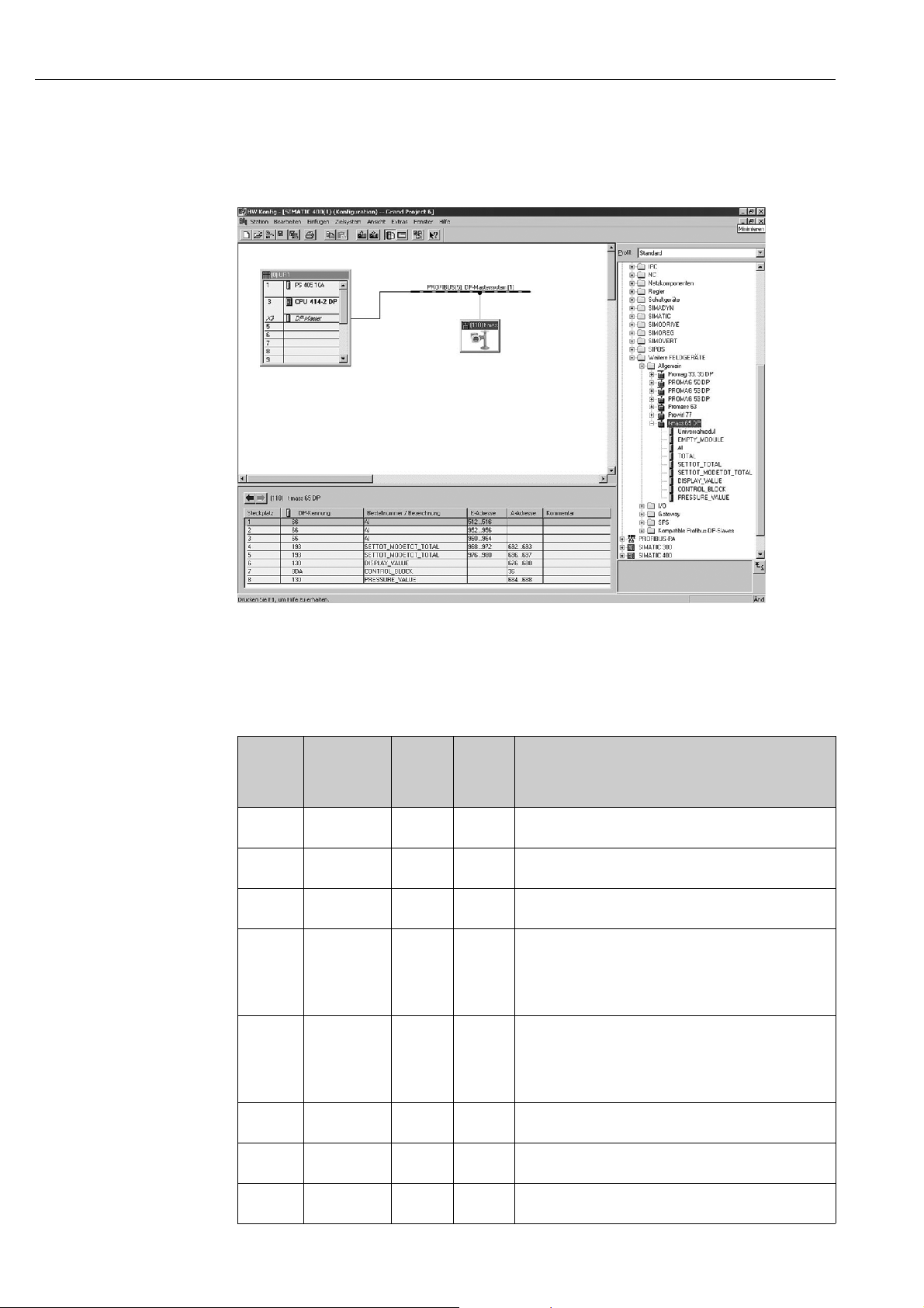
Commissioning Proline t-mass 65 PROFIBUS DP/PA
6.7.4 Configuration examples with Simatic S7 HW-Konfig
Example 1
Fig. 42: Complete configuration using the t-mass 65 GSD file
It is essential to adhere to the following sequence when configuring the modules in the
PROFIBUS Master (class 1):
Byte
Slot
sequence
1AI5-
2AI5-
3AI5-
4
5
Module
SETTOT
_MODETOT
_TOTAL
SETTOT
_MODETOT
_TOTAL
length
input
data
52
52
Byte
length
output
data
Description
Analog Input function block 1
Output variable mass flow (factory setting)
Analog Input function block 1
Output variable corr. volume flow (factory setting)
Analog Input function block 1
Output variable temperature (factory setting)
Totalizer function block 1
TOTAL output variable = totalized mass flow (factory setting)
SETTOT totalizer control
MODETOT totalizer configuration
Totalizer function block 2
TOTAL output variable = totalized mass flow (factory setting)
SETTOT totalizer control
MODETOT totalizer configuration
a0005497
6
7
8
DISPLAY
_VALUE
CONTROL
_BLOCK
PRESSURE
_VALUE
-5
-1
-5
Value for local display
Control of device functions
Process pressure
80 Endress+Hauser
Page 81
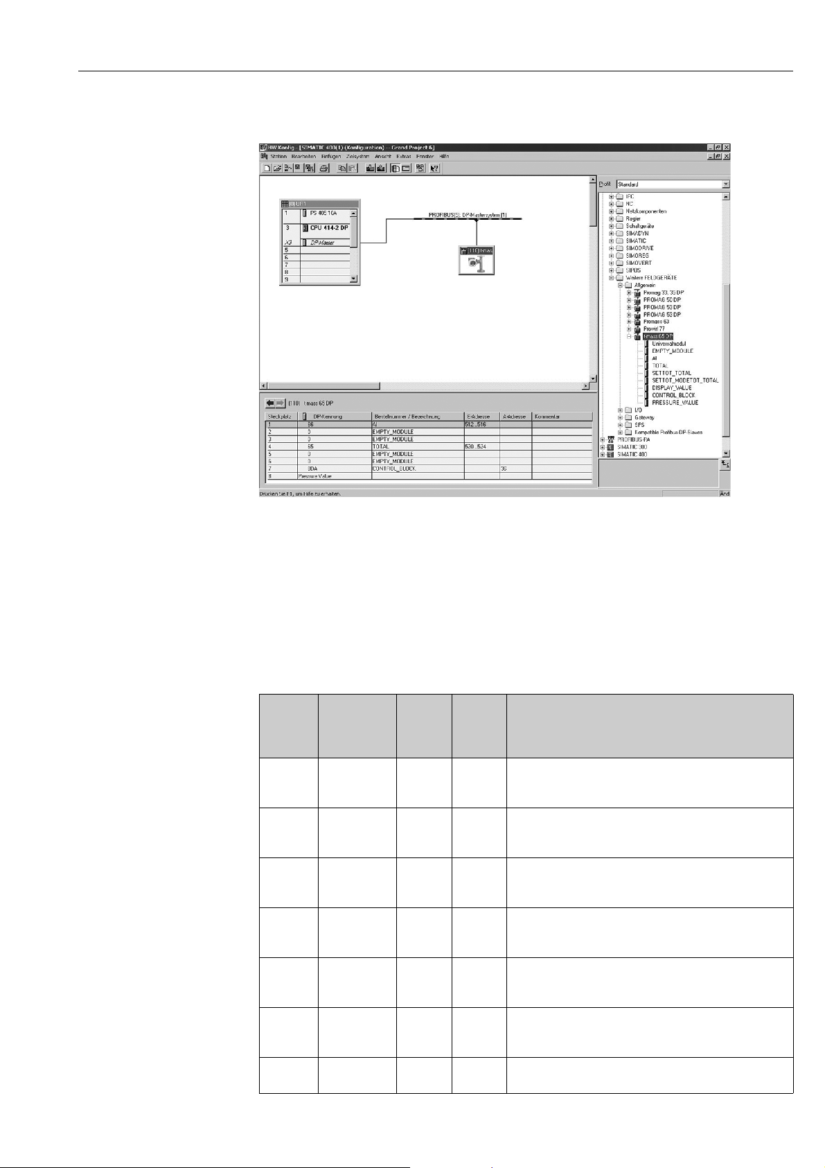
Proline t-mass 65 PROFIBUS DP/PA Commissioning
Example 2
a0005498
Fig. 43: In this example, modules that are not needed are replaced by the module EMPTY_MODULE.
The t-mass 65 GSD file is used .
With this configuration, the Analog Input function block 1 (slot 1), the totalizer value TOTAL
(slot 4) and the cyclic control of device functions CONTROL_BLOCK (slot 7) are activated.
The mass flow (factory setting) is read out cyclically by the measuring device by means of Analog
Input function block 1. The totalizer is configured "without configuration". In other words, in this
example it only returns the totalizer value for the mass flow (factory setting) by means of the TOTAL
module and cannot be controlled by the PROFIBUS Master (class 1).
Byte
Slot
sequence
1AI5-
2
3
Module
EMPTY
_MODULE
EMPTY
_MODULE
length
input
data
--
--
Byte
length
output
data
Description
Analog Input function block 1
Output variable mass flow (factory setting)
Empty
Empty
4TOTAL5-
5
6
7
EMPTY
_MODULE
EMPTY
_MODULE
CONTROL
_BLOCK
--
--
-1
Totalizer function block 1
TOTAL output variable = totalized mass flow (factory setting)
Empty
Empty
Control of device functions
Endress+Hauser 81
Page 82

Commissioning Proline t-mass 65 PROFIBUS DP/PA
6.8 PROFIBUS DP/PA acyclic data transmission
Acyclic data transmission is used to transmit parameters during commissioning or maintenance, or
to display additional measured variables that are not included in data transmission. Thus parameters
for identification, control or adjustment in the various blocks (physical block, transducer block,
function block) can be changed while the device is in the process of data transmission with a PLC.
The measuring device supports the two basic types of acyclic data transmission:
• MS2AC communication with 2 available SAP´s
• MS1AC communication
6.8.1 Master class 2 acyclic (MS2AC)
MS2AC is acyclic data transmission between a field device and a Master (class 2), e.g. FieldCare,
Siemens PDM etc. ä 41. During this process, the master opens a communication channel via
an SAP (Service Access Point) to access the device.
All parameters to be exchanged with a device via PROFIBUS must be made known to a Class 2
master. This assignment to each individual parameter takes place either in a device description
(DD), a DTM (Device Type Manager), or inside a software component in the master via slot and
index addressing.
When using MS2AC communication, note the following:
• As described above, a Master (class 2) accesses a device via special SAP´s.
Therefore, the number of Master (class 2) that can communicate with a device simultaneously is
limited to the number of SAPs available for this data transmission.
• The use of a Master (class 2) increases the cycle time of the bus system. This must be taken into
account when programming the control system used.
6.8.2 Master class 1 acyclic (MS1AC)
In MS1AC, a cyclic master, that is already reading the cyclic data from the device or writing to the
device opens the communication channel via the SAP 0x33 (special Service Access Point for
MS1AC) and can then read or write a parameter acyclically like a Class 2 master via the slot and
the index (if supported).
When using MS1AC communication, note the following:
• Currently, few PROFIBUS masters on the market support this data transmission.
• MS1AC is not supported by all PROFIBUS devices.
• In the user program, note that constant writing of parameters (for example, at every cycle of the
program) can drastically reduce the service life of a device. Acyclically written parameters are
written to voltage-resistant memory modules (EEPROM, Flash etc.). These memory modules are
designed for a limited number of write operations. In normal operation without MS1AC (during
parameter configuration), the number of write operations does not even come close to this
number. If programming is incorrect, this maximum number can be reached quickly, drastically
reducing a device's service life.
Note!
!
The memory module of the measuring device is designed for one million write operations.
82 Endress+Hauser
Page 83
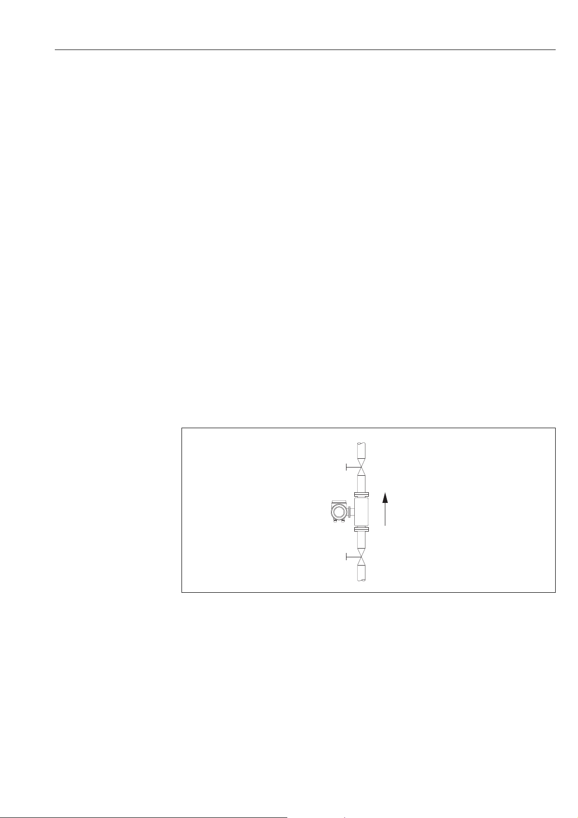
Proline t-mass 65 PROFIBUS DP/PA Commissioning
1
2
6.9 Adjustment
6.9.1 Zero point adjustment
Calibration takes place under reference operating conditions. ( ä 109).
Consequently, the zero point adjustment is generally not necessary!
At zero flow conditions, the output of most thermal mass flow devices has a strong dependency on
the process pressure. The effect on the true zero point of the device, by the static line pressure, is
dependant on the gas type and the application demands and in many cases the use of the low flow
cut-off function is adequate to zero the device output.
However, with some gases and /or a combination of high static line pressures, the zero point may
need to be adjusted under process conditions to restore the very low measurement capability of the
device.
Therefore, the zero point adjustment is advisable in the following special cases:
• To achieve highest measuring accuracy with very small flow rates.
• Under process or operating conditions where the gas properties (heat capacity and thermal
conductivity) will change e.g. Hydrogen and Helium.
Preconditions for a zero point adjustment
Note the following before you perform a zero point adjustment:
• A zero point adjustment can be performed only with gases that contain no solid contents or
condensate.
• The adjustment is performed with the process gas at zero flow and at operating pressure. This can
be achieved, for example, with shut-off valves upstream and/or downstream of the sensor.
– Normal operation valves 1 and 2 open
– Zero point adjustment with pump pressure Valve 1 open / valve 2 closed
– Zero point adjustment without pump pressure Valve 1 closed / valve 2 open
a0003601
Fig. 44: Zero point adjustment and shut-off valves
!
Endress+Hauser 83
Note!
You can view the currently valid zero point value using the ZERO POINT function in the SENSOR
DATA group (see the "Description of Device Functions" manual, BA000114D/06/…).
Page 84

Commissioning Proline t-mass 65 PROFIBUS DP/PA
Performing a zero point adjustment
1. Operate the system until operating conditions have settled.
2. Stop the flow (v = 0 m/s).
3. Check the shut-off valves for leaks.
4. Check that operating pressure is correct.
5. Using the local display, select the ZEROPOINT ADJUSTMENT function in the function matrix:
PROCESS PARAMETER ZERO POINT ADJUST
6. When you press O or S you are automatically prompted to enter the access code if the
function matrix is still disabled. Enter the code (factory setting = 65).
7. Use O or S to select START and press F to confirm. The zero point adjustment now starts
and is completed within a few seconds.
Note!
!
If the flo w in the p ipe is un stable, the following error message may appear on the display "ZERO
ADJUST FAIL". The zero point adjustment has failed. The preconditions need to be stabilised
before attempting a new adjustment.
8. Back to the HOME position:
– Press and hold down Esc key (X) for longer than three seconds or
– Repeatedly press and release the Esc key (X).
Resetting a zero point adjustment
The currently stored zero point can be reset to the original factory value by using the RESET option
within ZERO POINT ADJUST.
Use O or S to select RESET and press F to confirm. The zero point adjustment is now reset.
6.10 Data storage device (HistoROM)
At Endress+Hauser, the term HistoROM refers to various types of data storage modules on which
process and measuring device data are stored. By plugging and unplugging such modules, device
configurations can be duplicated onto other measuring devices to cite just one example.
6.10.1 HistoROM/S-DAT (sensor-DAT)
The HistoROM/S-DAT is an exchangeable data storage device in which all sensor relevant
parameters are stored, i.e., pipe type, diameter, serial number, flow conditoner, zero point.
6.10.2 HistoROM/T-DAT (transmitter-DAT)
The HistoROM/T-DAT is an exchangeable data storage device in which all transmitter parameters
and settings are stored.
Storing of specific parameter settings from the EEPROM to the HistoROM/T-DAT and vice versa
has to be carried out by the user (= manual save function). Detailed instructions ä 58.
84 Endress+Hauser
Page 85

Proline t-mass 65 PROFIBUS DP/PA Maintenance
7 Maintenance
Generally, the flowmeter requires no special maintenance work, particularly if the gas is clean and
dry.
#
Warning!
Hazardous area approvals may demand that the device be returned to an Endress+Hauser
production centre for service ( ä 106) or that work can only be carried out by a qualified
Endress+Hauser service person. Consult your Endress+Hauser service representative for more
information.
7.1 External cleaning
When cleaning the exterior of measuring devices, always use cleaning agents that do not attack the
surface of the housing and the seals.
7.2 Pipe cleaning
The sensor is capable of withstanding clean in place (CIP) processes using heated liquids or steam
(SIP), within the maximum specified temperature limits. However the sensor measurement will be
adversely affected during the cleaning cycle and a settling down period will be required after the
cycle to allow the process and sensor temperatures to re-stabilise.
!
"
"
Note!
The POSITIVE ZERO RETURN function maybe activated to set the current output to zero flow
during such cycles. See "Description of Device Functions" manual for more information.
Caution!
Do not use a pipe cleaning pig.
7.3 Transducer cleaning
For gases that do carry impurities, it is recommended that the sensor be routinely inspected and
cleaned to minimise any potential measuring errors due to contamination or build-ups. The
frequency of inspection and cleaning will depend upon the application and expected measurement
performance.
Cleaning is performed by applying a non-filming or oil-free type cleaning fluid to a soft brush or cloth
and gently wiping over the surface until all build-ups and contaminants are removed.
Caution!
• Use care not to bend the sensing elements of the transducer during cleaning.
• Do not use abrasive materials or fluids corrosive to the sensor materials and seals.
Sensor-specific information:
•t-mass F sensor:
Removal of the transducer requires specialist knowledge, tools and parts. The process seal also
may need to be tested and re-qualified. This procedure must be carried out by an Endress+Hauser
production centre.
•t-mass I sensor:
When removing the measuring sensor, observe the safety guidelines in chapter "Installation"
ä 19.
Endress+Hauser 85
Page 86

Maintenance Proline t-mass 65 PROFIBUS DP/PA
7.4 Replacing seals
Under normal circumstances, fluid wetted seals of the sensor do not require replacement.
Replacement is necessary only in special circumstances, for example if aggressive or corrosive fluids
are incompatible with the seal material.
Sensor-specific information:
•t-mass F sensor:
The sensor contains o-rings seals and a bushing. In case of failure, the device must be returned to
an Endress+Hauser production centre for inspection and repair. ä 106
•t-mass I sensor:
The transducer is welded to the insertion tube and has no exchangeable seals. The compression
fitting contains wetted seals (ferrules) and a bonded seal is used on the G 1 A thread version.
Caution!
"
Do not reuse gaskets after removing sensors.
Use only original parts from Endress+Hauser. The compression fitting and gasket seals are
deliverable as spare parts. The seal ring can be replaced easily on site
7.5 In-situ calibration
The t-mass flowmeters are designed to support in-situ calibration using a reference meter signal,
thus saving time and cost by reducing the need for factory re-calibration.
Pre-requirements for in-situ calibration with adjustment:
1. Stable gas composition (operation with one gas group only; without gas analyzer input)
2. Stable pressure and temperature (without pressure compensation input)
3. Mass flow reference
a. mass flow reference meter, mounted in the measurement or bypass pipe, providing a mA
signal to t-mass or
b. manual entry of known mass flow reference values. For example, the display value from
the reference meter or a derived value from a pump curve)
4. Ability to control the flow range over a minimum of 5 control points
This function is activated using the service access code.
Please discuss your specific requirements with your Endress+Hauser service representative.
7.6 Recalibration
For thermal meters, the interval between calibrations is dependent on the application since
calibration drift is predominantly caused by contamination of the sensor surface.
If the gas is not clean (i.e. contains particulates), then gentle cleaning of the sensor elements can be
effective at regular intervals. The cleaning interval will depend upon the nature and extent of the
contamination.
Determination of recalibration intervals:
• If the measurement is critical, then a calibration audit should be undertaken by performing
recalibration checks once per year for a period of 2 years. Increase that period to twice per year
if the application gas is not clean and dry. Depending on the results of the audit, the next
recalibration check interval can be increased or decreased accordingly.
• For non-critical applications and or where the gas is clean and dry, a recalibration interval of every
2 to 3 years is recommended.
86 Endress+Hauser
Page 87
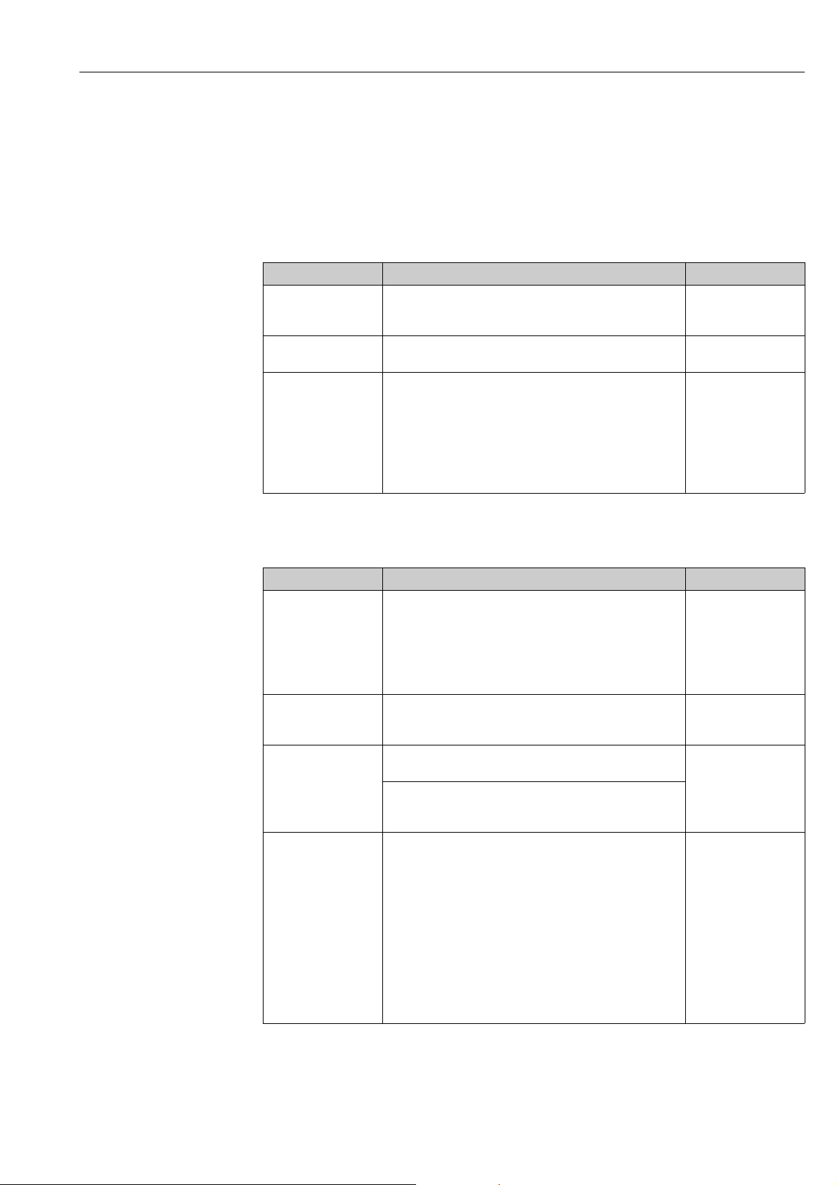
Proline t-mass 65 PROFIBUS DP/PA Accessories
8 Accessories
Various accessories, which can be ordered separately from Endress+Hauser, are available for the
transmitter and the sensor. Detailed information on the order code in question can be obtained from
your Endress+Hauser representative.
8.1 Device-specific accessories
Accessory Description Order code
Mounting boss Mounting boss for the t-mass insertion sensor
•G 1 A thread
•1" NPT female thread
Cable remote Connecting cable for the remote version sensor and transmitter
(per m (ft), up to 100m (328ft) max.)
Transmitter t-mass 65 Transmitter for replacement or for stock. Use the order code to
define the following specifications:
•Approvals
• Degree of protection / version
• Cable entries
• Display / power supply / operation
•Software
• Outputs / inputs
DK6MB - ***
DK6CA - **
65XXX-XXXXXX******
8.2 Measuring principle-specific accessories
Accessory Description Order code
Mounting set for
transmitter
Flow conditioner Perforated plate flow conditioner:
Hot tap Mounting set with ball valve and safety chain. Insertion or
Graphic data manager
Memograph M
Mounting set for remote version. Suitable for:
– Wall mounting
– Pipe mounting
– Installation in control panel
Mounting set for aluminium field housing:
Suitable for pipe mounting (¾" to 3")
• t-mass F sensor (DN25 to 100, 1"to 4")
• t-mass I sensor (DN80 to 300, 3" to 12")
extraction of sensor under process pressure (max. 4 bar, 58 psi).
Mounting set with ball valve and spindle retractor. Insertion or
extraction of sensor under process pressure (max. 16 bar,
235 psi).
The graphic data manager Memograph M provides information on
all the relevant process variables. Measured values are recorded
correctly, limit values are monitored and measuring points
analyzed. The data are stored in the 256 MB internal memory and
also on an SD card or USB stick.
Memograph M boasts a modular design, intuitive operation and a
comprehensive security concept. The ReadWin® 2000 PC
software is part of the standard package and is used for configuring,
visualizing and archiving the data captured.
The mathematics channels which are optionally available facilitate
continuous monitoring, e.g. of specific energy consumption, boiler
efficiency and other parameters which are necessary for efficient
energy management.
DK6WM - *
DK6ST-***
DK7ST-***
Please refer to the
product page of the
Endress+Hauser Internet
page:
www.endress.com
RSG40 - ************
Endress+Hauser 87
Page 88

Accessories Proline t-mass 65 PROFIBUS DP/PA
8.3 Service-specific accessories
Accessory Description Order code
Applicator Software for selecting and sizing Endress+Hauser measuring
devices:
• Calculation of all the necessary data for identifying the
optimum flowmeter: e.g. nominal diameter, pressure loss,
accuracy or process connections
• Graphic illustration of the calculation results
Administration, documentation and access to all project-related
data and parameters over the entire life cycle of a project.
Applicator is available:
• Via the Internet: https://wapps.endress.com/applicator
• On CD-ROM for local PC installation.
Fieldcheck Tester/simulator for testing flowmeters in the field.
When used in conjunction with the "FieldCare" software package,
test results can be imported into a database, printed and used for
official certification.
Contact your Endress+Hauser representative for more
information.
FieldCare FieldCare is Endress+Hauser's FDT based Plant Asset
Management Tool. It can configure all intelligent field devices in
your plant and supports you in managing them. By using status
information, it also provides a simple but effective means of
checking their health.
FXA193 The FXA193 service interface connects the device to the PC for
configuration via FieldCare.
DKA80 - *
50098801
Please refer to the
product page of the
Endress+Hauser Internet
page:
www.endress.com
FXA193 – *
88 Endress+Hauser
Page 89
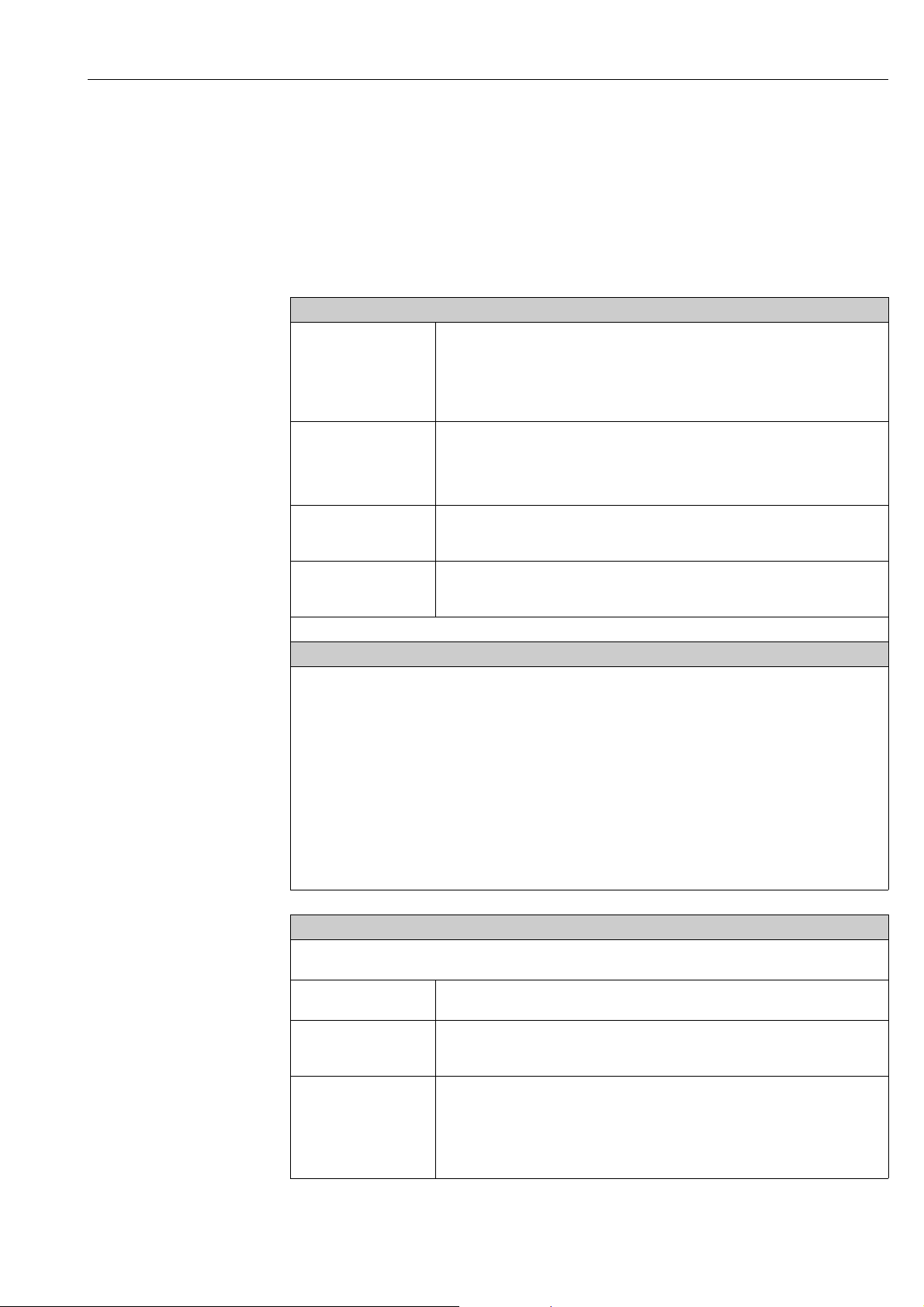
Proline t-mass 65 PROFIBUS DP/PA Trouble-shooting
9 Trouble-shooting
9.1 Trouble-shooting instructions
Always start trouble-shooting with the following checklist if faults occur after commissioning or
during operation. The routine takes you directly to the cause of the problem and the appropriate
remedial measures.
Check the display
No display visible and no
output signals present.
No display visible, but
output signals are present.
Display texts are in a
foreign language.
Measured value indicated,
but no signal at the current
or pulse output
▼
Error messages on display
Errors that occur during commissioning or measuring are displayed immediately.
Error messages consist of a variety of icons.
The meanings of these icons are as follows (example):
– Type of error: S = System error, P = Process error
– Error message type: $ = Fault message, ! = Notice message
– FLOW LIMIT = Error designation, e.g. measured flow has exceeded the maximum limit.
– 03:00:05 = Duration of error occurrence (in hours, minutes and seconds)
– #422 = Error number
1. Check the supply voltage Terminals 1, 2
2. Check device fuse ä 105
85 to 260 V AC: 0.8 A slow-blow / 250 V
20 to 55 V AC and 16 to 62 V DC: 2 A slow-blow / 250 V
3. Measuring electronics defective order spare parts ä 99
1. Check whether the ribbon-cable connector of the display module is correctly plugged
into the amplifier board ä 99 ff..
2. Display module defective order spare parts ä 99
3. Measuring electronics defective order spare parts ä 99
Switch off power supply. Press and hold down both the P keys and switch on the
measuring device. The display text will appear in English (default) and is displayed at
maximum contrast.
Measuring electronics defective order spare parts ä 99
Caution!
"
• See the information on ä 40.
• The measuring system interprets simulations and positive zero return as system errors, but displays them as notice
message only.
▼
Faulty connection to PROFIBUS Master
No connection can be made between the PROFIBUS Master and the device.
Check the following points:
Supply voltage
Transmitter
Device fuse Check device fuse ä 105
Fieldbus connection Check data line:
▼
Check the Supply voltage Terminals 1/2
85 to 260 V AC: 0.8 A slow-blow / 250 V
20 to 55 V AC and 16 to 62 V DC: 2 A slow-blow / 250 V
Terminal 26 = B (RxD/TxD-P)
Terminal 27 = A (RxD/TxD-N)
Endress+Hauser 89
Page 90
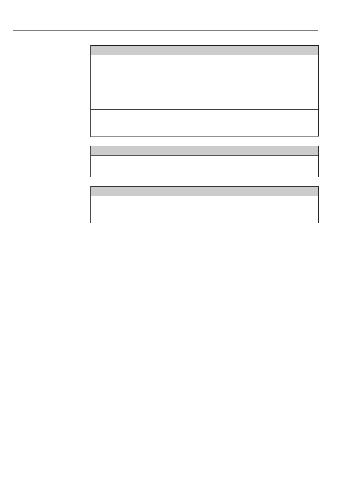
Trouble-shooting Proline t-mass 65 PROFIBUS DP/PA
Faulty connection to PROFIBUS master (continued)
Network structure Check permissible fieldbus length and number of spurs.
Fieldbus address Check fieldbus address: make sure there are no double assignments.
Bus termination Has the PROFIBUS network been terminated correctly?
Each bus segment must always be terminated with a bus terminator at both ends (start and
finish). Otherwise there may be interference in communication.
▼
System or process error messages
System or process errors which occur during commissioning or operation can be displayed in ACTUAL SYSTEM
CONDITION function via local display or by using an operating program ä 41.
▼
Other error (without error message)
Some other error has
occurred
Diagnosis and rectification ä 97.
"
!
9.2 System error messages
Serious system errors are always recognized by the flowmeter as "Fault message", and are shown
as a lightning flash ($) on the display! Fault messages immediately affect the operation. Simulations
and positive zero return, on the other hand, are classed and displayed as "Notice messages".
Caution!
In the event of a serious fault, a flowmeter might have to be returned to the manufacturer for repair.
Important procedures must be carried out before you return a flowmeter to Endress+Hauser.
ä 106. Always enclose a duly completed "Declaration of contamination" form. You will find a
preprinted blank of this form at the back of this manual.
Note!
Also observe the information on the following pages ä 40
9.2.1 Displaying the device status on PROFIBUS DP
Display in the operating program (acyclic data transmission)
The device status can be queried using an operating program (e.g. FieldCare):
Function block SUPERVISION ACTUAL SYSTEM CONDITION
90 Endress+Hauser
Page 91
Proline t-mass 65 PROFIBUS DP/PA Trouble-shooting
Quality
Code
Measuring value
Limits
Quality Substatus
Quality
Status
Byte 5
Display in the PROFIBUS master system (cyclic data transmission)
If the AI or TOTAL modules are configured for cyclic data transmission, the device status is coded
in accordance with PROFIBUS Profile Specification 3.0 and transmitted with the variable to the
PROFIBUS master by means of the quality byte (byte 5). The quality byte is split into the "quality
status", "quality substatus" and "limits" segments.
a0002707-en
Fig. 45: Structure of the quality byte
The content of the quality byte depends on the failsafe mode error behavior configured in the
corresponding Analog Input function block 1 to 3 or totalizer function block 1 to 2.
Depending on which failsafe mode has been set in the FAILSAFE_TYPE function, the following
status information is transmitted to the PROFIBUS master via the quality byte:
• For the selection FAILSAFE_TYPE FSAFE VALUE :
• For the selection FAILSAFE_TYPE LAST GOOD VALUE (factory setting):
If a valid output value was available before the failure:
If no valid output value was available before the failure:
• For FAILSAFE_TYPE WRONG VALUE:
!
Note!
The FAILSAFE_TYPE function can be configured in the corresponding Analog Input function block
1 to 3 or Totalizer function block 1 to 2 by means of an operating program (e.g. FieldCare).
Quality code (HEX) Quality status Quality substatus Limits
0x48
0x49
0x4A
Quality code (HEX) Quality status Quality substatus Limits
0x44
0x45
0x46
Quality code (HEX) Quality status Quality substatus Limits
0x4C
0x4D
0x4E
UNCERTAIN Substitute-Set
UNCERTAIN Last usable value
UNCERTAIN Initial Value
For status information, see the table in the following section.
OK
Low
High
OK
Low
High
OK
Low
High
Endress+Hauser 91
Page 92

Trouble-shooting Proline t-mass 65 PROFIBUS DP/PA
9.2.2 List of system error messages
PROFIBUS measured value status
Extended
diagnostic
message in the
No. Device status message
(local display)
S = System error
$ = Fault message (with an effect on the current operation)
! = Notice message (without any effect on the current operation)
No. # 0xx Hardware error
001 S: CRITICAL FAIL
$: # 001
011 S: AMP HW EEPROM
$: # 011
012 S: AMP SW EEPROM
$: # 012
014 S: AMP SW-ROM/RAM
$: # 014
031 S: SENSOR HW DAT
$: # 031
032 S: SENSOR SW DAT
$: # 032
Quality code (HEX)
Measured variable status
0x0F BAD Device Failure Constant ROM/RAM
0x0F BAD Device Failure Constant Amplifier EEPROM
0x0F BAD Device Failure Constant Amp. EEPROM
0x0F BAD Device Failure Constant Amp. ROM/RAM
0x10
0x11
0x12
0x10
0x11
0x12
Quality status
BAD Sensor Failure O.K.
BAD Sensor Failure O.K.
Quality substatus
Low
High
Low
High
PROFIBUS
master
Limits
failure
failure
data inconsistent
data inconsistent
S-DAT failure / not
inserted
S-DAT data
inconsistent
Remedy / spare parts
Spare parts ä 99
Cause:
Serious device error
Remedy:
Replace the amplifier board.
Cause:
Amplifier: Defective EEPROM
Remedy:
Replace the amplifier board.
Cause:
Measuring amplifier: Error when accessing data of
the EEPROM
Remedy:
Replace the amplifier board.
Cause:
Amplifier: Defective ROM/RAM
Remedy:
Replace the amplifier board.
Cause:
Sensor DAT:
1. HistoROM/S-DAT is defective.
2. HistoROM/S-DAT is not plugged into the
amplifier board or is missing.
Remedy:
1. Replace the S-DAT.
Check the spare parts set number to ensure
that the new, replacement DAT is compatible
with the measuring electronics.
2. Plug the S-DAT into the amplifier board
ä 100, ä 102
Cause:
Error accessing the calibration values stored in the
HistoROM/S-DAT.
Remedy:
1. Check whether the HistoROM/S-DAT is
correctly plugged into the amplifier
board ä 100, ä 102
2. Replace the S-DAT if it is defective.
Before replacing the DAT, check that the new,
replacement DAT is compatible with the
measuring electronics. Check the:
– Spare parts set number
– Hardware revision code
3. Replace measuring electronics boards if
necessary.
92 Endress+Hauser
Page 93

Proline t-mass 65 PROFIBUS DP/PA Trouble-shooting
PROFIBUS measured value status
Extended
diagnostic
No. Device status message
(local display)
035 S: SENS HW-ROM/RAM
$: # 035
036 S: SENS SW-ROM/RAM
$: # 036
042 S: TRANSM. SW-DAT
$: # 042
051 AC COMPATIB.
$: # 051
070 S: SENSOR DEFECT
$: # 070
No. # 1xx Software error
111 S: CHECKSUM TOTAL
$: # 111
Quality code (HEX)
Measured variable status
0x10
0x11
0x12
0x10
0x11
0x12
0x0F BAD Device Failure Constant T-DAT data
0x0F BAD Device Failure Constant Compatibility Amp.
0x13 BAD Sensor Failure Constant Sensor failure Cause:
0x0F BAD Device Failure Constant Totalizer checksum
Quality status
BAD Sensor Failure O.K.
BAD Sensor Failure O.K.
Quality substatus
Low
High
Low
High
message in the
PROFIBUS
master
Limits
Sensor:
Defective ROM/
RAM
Sensor:
Defective ROM/
RAM
inconsistent
I/O module
error
Remedy / spare parts
Spare parts ä 99
Cause:
Sensor: Defective ROM/RAM
Remedy:
Replace the remote amplifier board.
Cause:
Sensor: Defective ROM/RAM
Remedy:
Replace the remote amplifier board.
Cause:
Error accessing the calibration values stored in the
HistoROM/T-DAT.
Remedy:
1. Check whether the HistoROM/T-DAT is
correctly plugged into the amplifier board.
ä 100, ä 102
2. Replace the HistoROM/T-DAT if it is
defective. ä 99,
Before replacing the DAT, check that the new,
replacement DAT is compatible with the
measuring electronics. Check the:
– Spare parts set number
– Hardware revision code
3. Replace measuring electronics boards if
necessary.
Cause:
The I/O board and the amplifier board are not
compatible.
Remedy:
Use only compatible modules and boards.
Check the compatibility of the modules used.
Check the:
– Spare parts set number
– Hardware revision code
Flow sensors are likely to be defect, measurement
is no longer possible.
Remedy:
Contact your Endress+Hauser representative.
Cause:
Totalizer checksum error
Remedy:
1. Restart the measuring device
2. Replace the amplifier board if necessary.
Endress+Hauser 93
Page 94

Trouble-shooting Proline t-mass 65 PROFIBUS DP/PA
PROFIBUS measured value status
Extended
diagnostic
No. Device status message
(local display)
121 S: A/C SW COMPATI.
$: # 121
No. # 2xx Error in DAT/no communication
205 S: LOAD T-DAT
!: # 205
206 S: SAVE T-DAT
!: # 206
211 S: S-DAT NO HW
$: # 211
251 S: COMMUNIC. SENS
$: # 251
261 S: COMMUNICAT. I/O
$: # 261
Quality code (HEX)
Measured variable status
0x0F BAD Device Failure Constant Amp- I/O soft only
0x0F BAD Device Failure Constant Save to T-DAT
0x0F BAD Device Failure Constant Restore from
0x0F BAD Device Failure Constant S-DAT no
0x0F BAD Device Failure Constant Communication
0x18
0x19
0x1A
BAD No
Quality status
Communica-
Quality substatus
tion
O.K.
Low
High
message in the
PROFIBUS
master
Limits
part. comp.
failed
T-DAT failed
hardware
sensor failure
Communication
I/O failure
Remedy / spare parts
Spare parts ä 99
Cause:
Due to different software versions, I/O board and
amplifier board are only partially compatible
(possibly restricted functionality).
Note!
!
– This message is only listed in the error history.
– Nothing is displayed on the display.
Remedy:
Module with lower software version has either to
be actualized by FieldCare with the required
software version or the module has to be replaced.
Cause:
Data backup (downloading) to
HistoROM/T-DAT failed, or error when accessing
(uploading) the calibration values stored in the
HistoROM/T-DAT.
Remedy:
1. Check whether the HistoROM/T-DAT is
correctly plugged into the amplifier board.
2. Replace the HistoROM/T-DAT if it is
defective. ä 99
Before replacing the DAT, check that the new,
replacement DAT is compatible with the
measuring electronics. Check the:
– Spare parts set number
– Hardware revision code
3. Replace measuring electronics boards if
necessary. ä 99
Cause:
HistoROM/S-DAT is not fitted to amplifier board.
Remedy:
Check whether the S-DAT is correctly plugged into
the amplifier board ä 100
Cause:
Internal microprocessor communication fault on
the amplifier board.
Remedy:
Remove the amplifier board.
Cause:
No data reception between amplifier and I/O board
or faulty internal data transfer.
Remedy:
Check whether the electronics boards are correctly
inserted in their holders ä 100
94 Endress+Hauser
Page 95
Proline t-mass 65 PROFIBUS DP/PA Trouble-shooting
PROFIBUS measured value status
Extended
diagnostic
No. Device status message
(local display)
No. # 3xx System limits exceeded
372 S: DIFF. TEMP. LOW
$: # 372
381 S: FLUIDTEMP.MIN.
!: # 381
382 S: FLUIDTEMP.MAX.
!: # 382
No. # 5xx Application error
501 S: SW.-UPDATE ACT
!: # 501
502 S: UP-/DOWL. ACT.
!: # 502
No. # 6xx Simulation mode active
601 S: POS. ZERO-RET.
! # 601
Quality code (HEX)
0x13 BAD Sensor Failure Constant Diff. Temp. is
0x40
0x41
0x42
0x40
0x41
0x42
0x48
0x49
0x4A
0x48
0x49
0x4A
0x53 UNCERTAIN Sensor
Measured variable status
Quality status
UNCERTAIN O.K. O.K.
UNCERTAIN O.K. O.K.
UNCERTAIN Substitute-Set O.K.
UNCERTAIN Substitute-Set O.K.
Quality substatus
conversion
not accurate
Low
High
Low
High
Low
High
Low
High
Constant Positive zero return
message in the
PROFIBUS
master
Limits
below limit
Fluid temperature
min.
Fluid temperature
max.
Software upload
active
Up-/Download
active
active
Remedy / spare parts
Spare parts ä 99
Cause:
The measured sensor differential temperature is
below limit value.
Remedy:
Reduce the flow rate or consider replacing the
instrument with a suitable size for the application if
possible.
Cause:
The minimum fluid temperature limit for the
transducer has been exceeded.
Remedy:
Increase the process gas temperature.
Achtung!
"
Caution! In case of severe temperature exposure,
the transducer may be damaged.
Cause:
The minimum fluid temperature limit for the transducer has been exceeded.
Remedy:
Reduce the process gas temperature.
Achtung!
"
Caution! In case of severe temperature exposure,
the transducer may be damaged.
Cause:
New amplifier or communication (I/O module)
software version is loaded. Currently no other
functions are possible.
Remedy:
Wait until process is finished. The device will
restart automatically.
Cause:
Up- or downloading the device data via
configuration program. Currently no other
functions are possible.
Remedy:
Wait until process is finished.
Cause:
Positive zero return is active.
Note!
!
This message has the highest display priority!
Remedy:
Switch off positive zero return.
Access:
SYSTEM PARAMETER POS. ZERO RETURN
( OFF)
Endress+Hauser 95
Page 96
Trouble-shooting Proline t-mass 65 PROFIBUS DP/PA
PROFIBUS measured value status
Extended
diagnostic
No. Device status message
(local display)
691 S: SIM. FAILSAFE
!: # 691
692 S: SIM. MEASURAND
!: # 692
698 S: DEV. TEST ACT.
!: # 698
Quality code (HEX)
Measured variable status
0x48
0x49
0x4A
0x60
0x61
0x62
0x60
0x61
0x62
Quality status
UNCERTAIN Substitute set O.K.
UNCERTAIN Simulated
Value
UNCERTAIN Simulated
Value
Quality substatus
Low
High
O.K.
Low
High
O.K.
Low
High
message in the
PROFIBUS
master
Limits
Simulation failsafe
active
Simulation
measured value
active
Device test via
Fieldcheck active
Remedy / spare parts
Spare parts ä 99
Cause:
Simulation of failsafe mode (outputs) is active.
Remedy:
Switch off simulation.
Access:
SIMULAT. SYSTEM FAILSAFE MODE
( OFF)
Cause:
Simulation of the measured value is active.
Remedy:
Switch off simulation.
Access:
SIMULAT. SYSTEM SIM. MEASURAND
( OFF)
Cause:
The measuring device is being checked on site via
the test and simulation device.
96 Endress+Hauser
Page 97
Proline t-mass 65 PROFIBUS DP/PA Trouble-shooting
9.3 Process error messages
!
Note!
Also observe the information on the following pages: ä 40 and ä 89
9.3.1 List of process error messages
PROFIBUS measured value status
No. Device status message
(local display)
Quality status
Quality code (HEX)
Measured variable status
P = Process error
$ = Fault message (with an effect on the current operation)
! = Notice message (without any effect on the current operation)
422 P: FLOW LIMIT
$: # 422
731 P: 0 ZERO-ADJ. N. OK.
$: # 731
0x13 BAD Sensor
0x13 BAD Sensor
Quality substatus
Failure
Failure
Extended
diagnostic
message in the
PROFIBUS
Limits
master
Constant Meas. flow
exceeded max limit
Constant Zero adjust is not okCause:
Remedy / spare parts
Cause:
The measured flow has exceeded the maximum
limit.
Remedy:
Reduce the flow rate or replace the instrument
with a suitable size for the application.
!
Error can be configured as a fault or notice
message.
The saved zero point is inaccurate possibly due to
unstable process or flow conditions.
Remedy:
Stabilize process conditions or relocate the
instrument to a more stable measuring location.
Note!
9.4 Process errors without messages
Symptoms Rectification
Note!
!
You may have to change or correct certain settings of the function matrix in order to rectify faults. The functions outlined below, such as DISPLAY DAMPING, for
example, are described in detail in the "Description of Device Functions" manual.
Displayed measured value fluctuates even
though flow is steady.
Device displays flow with no actual flow
present.
1. Increase value of the TIME CONSTANT setting CURRENT OUTPUT function group.
2. Increase value of the DISPLAY DAMPING setting USER INTERFACE function group.
3. The inlet and outlet lengths must be observed. See installation conditions ä 15
4. Consider the use of a flow conditioner. See installation conditions ä 16
5. Relocate the meter to a point where there is less flow disturbance
1. The low flow cut off value is programmed too low. Increase value of the ON VALUE LOW FLOW CUT OFF
setting PROCESS PARAMETERS function group (Factory setting = 1% of 20mA value).
2. Check for leaks in the pipe line downsteam of the sensor.
3. Reduce or eliminate pressure pulsations in the line.
Endress+Hauser 97
Page 98

Trouble-shooting Proline t-mass 65 PROFIBUS DP/PA
Symptoms Rectification
Device displays flow with no actual flow
present - but with high static line pressure
and thermally conductive gases present
(e.g. Hydrogen, Helium, etc.). Line
pressure is typically > 5 bar / 75 psi
Device displays zero flow but flow is
present.
Device displays incorrect flow value. 1. Check the basic parameters of the device (Quick Setup ä 48). Especially:
The fault cannot be rectified or some other
fault not described above has occurred.
In these instances, please contact your
Endress+Hauser representative.
Start the ZERO POINT ADJUST function PROCESS PARAMETERS function group.
See Zero Point Adjust function ä 83
Note!
!
Process preconditions are required before starting this function.
1. The INSTALLATION FACTOR may have a wrong setting = 0 PROCESS PARAMETERS function group (factory
setting = 1.0).
2. The LOW FLOW CUT OFF setting may be too high. Adjust the function ON VALUE LOW FLOW CUT OFF to a
lower value PROCESS PARAMTERS function group (factory setting 1% of calibrated 20mA value).
3. The ZERO POINT ADJUST function may have been incorrectly carried out with flow present. RESET the zero
point adjustment if necessary PROCESS PARAMETERS function group.
–Gas
– Process pressure
– Reference presssure and reference temperature
– Flow units
– Output assignment
2. Check the installation conditions (Post-installation check ä 26)
1. The inlet and outlet lengths must be observed ä 15.
2. Consider the use of a flow conditioner if the necessary inlet requirements cannot be met ä 16.
3. t-mass F: Check for diameter mismatch between the flanges and check the gasket alignment ä 13.
t-mass I: Check the sensor orientation and insertion depth. ä 19.
4. If the above actions do not resolve the problem, consider adjusting the INSTALLATION FACTOR so that the
displayed flow rate matches the expected flow rate PROCESS PARAMETERS function group (factory
setting 1.0).
3. The flow rate maybe too high (i.e. above sensor calibration range)
1. Check the sensor measuring range using the Endress+Hauser Applicator program.
2. Check if the inverted plus sign "+" is shown on the display? If yes, reduce the velocity if possible.
4. The flow rate maybe too low
1. Check the sensor measuring range using the E+H Applicator program.
2. Increase the velocity if possible.
5. Check the condition of the transducer
1. Are the measuring elements bent? If yes, replacement is necessary.
2. Are build-ups present? If yes, clean the sensors (Transducer cleaning ä 85).
3. Has corrosion occured? If yes, replacement is necessary.
6. Check if the gas is wet? Is condensate present on the sensors?
If yes:
1. For horizontal pipes: Mount the sensor at 135° ä 14
2. Install a condensate trap or filter upstream of the flowmeter
7. Check if heating devices are used upstream of the flowmeter causing possible temperature profile effects ?
If yes:
1. Relocate the flowmeter further downstream or
2. Install a flow conditioner upstream of the flowmeter
The following options are available for tackling problems of this nature:
Request the services of an Endress+Hauser service technician
If you contact our service representative to have a service technician sent out, please be ready with the following
information:
– Brief description of the fault
– Nameplate specifications : Order code and serial number ä 7
Returning devices to Endress+Hauser
The procedures on must be carried out before you return a flowmeter requiring repair or calibration to
Endress+Hauser. ä 6
n
Always e
"Declaration of contamination" at the back of this manual.
Replace transmitter electronics
Components in the measuring electronics defective order replacement ä 99
close a duly completed "Declaration of contamination" form with the flowmeter. You will find a preprinted
98 Endress+Hauser
Page 99
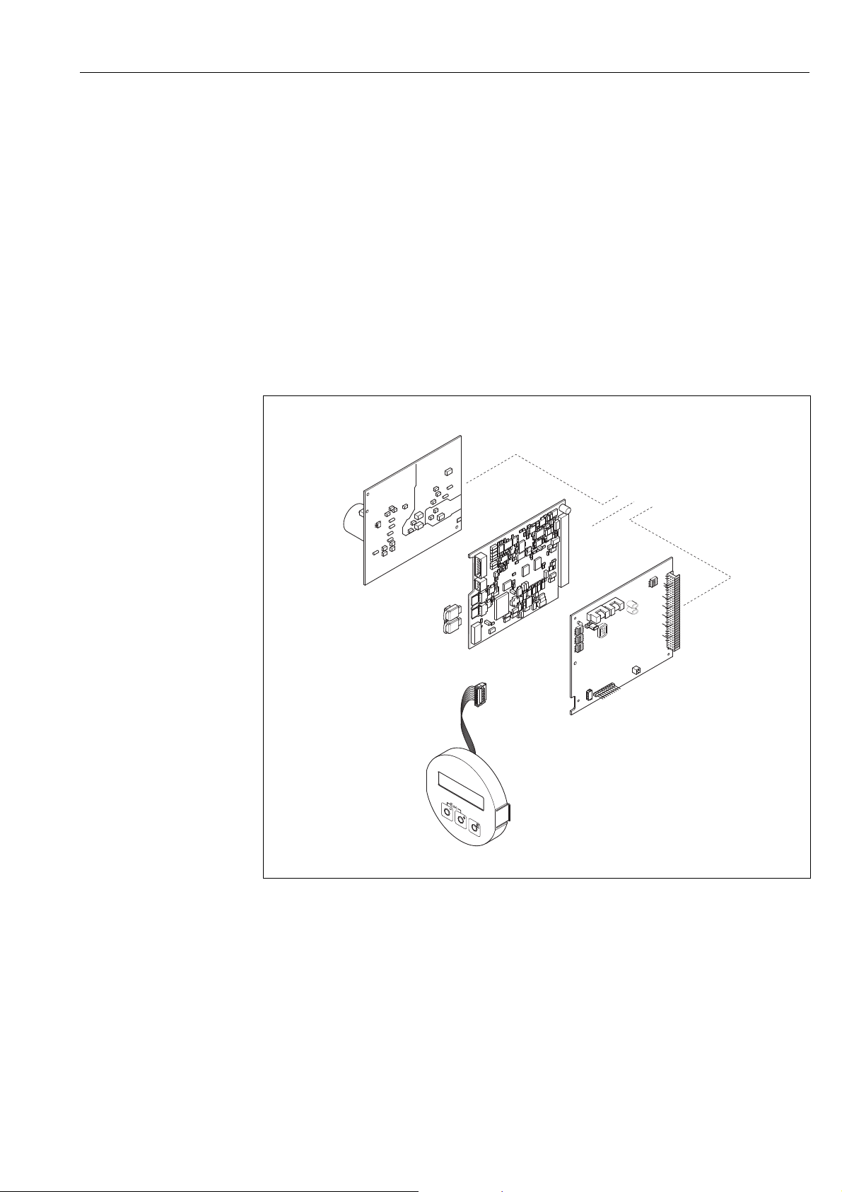
Proline t-mass 65 PROFIBUS DP/PA Trouble-shooting
1
2
3
4
5
6
1
2
3
4
W
E
N
O
1
2
3
4
W
E
N
O
1
2
3
4
W
E
N
O
1
2
3
4
W
E
N
O
9.5 Spare parts
The previous sections contain a detailed trouble-shooting guide. ä 89
The measuring device, moreover, provides additional support in the form of continuous selfdiagnosis and error messages.
Fault rectification can entail replacing defective components with tested spare parts. The illustration
below shows the available scope of spare parts.
!
Note!
You can order spare parts directly from your Endress+Hauser representative by providing the serial
number printed on the transmitter's nameplate. ä 7
Spare parts are shipped as sets comprising the following parts:
• Spare part
• Additional parts, small items (threaded fasteners, etc.)
• Mounting instructions
• Packaging
a0005495
Fig. 46: Spare parts for transmitter 65 (field and wall-mount housings)
1 Power unit board (85 to 260 V AC, 20 to 55 V AC, 16 to 62 V DC)
2 Amplifier board
3 I/O board (COM module)
4 HistoROM/S-DAT (sensor data memory)
5 HistoROM/T-DAT (transmitter data memory)
6 Display module
Endress+Hauser 99
Page 100

Trouble-shooting Proline t-mass 65 PROFIBUS DP/PA
9.5.1 Removing and installing printed circuit boards
Field housing
#
"
Warning!
• Risk of electric shock. Exposed components carry dangerous voltages. Make sure that the power
supply is switched off before you remove the cover of the electronics compartment.
• Risk of damaging electronic components (ESD protection). Static electricity can damage electronic
components or impair their operability. Use a workplace with a grounded working surface
purposely built for electrostatically sensitive devices!
• If you cannot guarantee that the dielectric strength of the device can be maintained during the
following steps, then an appropriate inspection test must be carried out in accordance with the
manufacturer’s specifications.
• When connecting Ex-certified devices, see the notes and diagrams in the Ex-specific supplement
to these Operating Instructions.
Caution!
Use only original Endress+Hauser parts.
Installation and removal å 47
1. Unscrew cover of the electronics compartment from the transmitter housing.
2. Remove the screws (1.1) and remove the cover (1) from the electronics compartment.
3. Disconnect the display ribbon cable (1.2) from the amplifier board.
4. Remove power supply board (3) and I/O board (5):
Insert a thin pin into the hole (2) provided for the purpose and pull the board clear of its holder.
5. Remove amplifier board (4):
– Disconnect the plug of the sensor signal cable (4.1) including HistoROM/S-DAT (4.2) and
HistoROM/T-DAT (4.3) from the board.
– Insert a thin pin into the hole (2) provided for the purpose and pull the board clear of its
holder.
6. Installation is the reverse of the removal procedure.
100 Endress+Hauser
 Loading...