

Endress+Hauser Proline t-mass 65 PROFIBUS DP, Proline t-mass 65 PROFIBUS DA Operating Instructions Manual
BA00113D/06/EN/14.14
71261905
Valid as of version
PROFIBUS DP V 3.06.XX (Device software)
PROFIBUS PA V 3.06.XX (Device software)
Products Solutions Services
Operating Instructions
Proline t-mass 65
PROFIBUS DP/PA
Thermal Mass Flowmeter
8

Proline t-mass 65 PROFIBUS DP/PA
Table of contents
1 Document information . . . . . . . . . . . . . . 3
1.1 Document conventions . . . . . . . . . . . . . . . . . . . . . . . 3
2 Safety instructions . . . . . . . . . . . . . . . . . 5
2.1 Designated use . . . . . . . . . . . . . . . . . . . . . . . . . . . . . 5
2.2 Installation, commissioning and operation . . . . . . 5
2.3 Operational safety . . . . . . . . . . . . . . . . . . . . . . . . . . . 6
2.4 Return . . . . . . . . . . . . . . . . . . . . . . . . . . . . . . . . . . . . . 6
2.5 Product safety . . . . . . . . . . . . . . . . . . . . . . . . . . . . . . 6
3 Identification . . . . . . . . . . . . . . . . . . . . . . 7
3.1 Device designation . . . . . . . . . . . . . . . . . . . . . . . . . . 7
3.2 Certificates and approvals . . . . . . . . . . . . . . . . . . 10
3.3 Registered trademarks . . . . . . . . . . . . . . . . . . . . . 10
4 Installation . . . . . . . . . . . . . . . . . . . . . . . 11
4.1 Incoming acceptance, transport and storage . . . 11
4.2 Installation conditions . . . . . . . . . . . . . . . . . . . . . 12
4.3 Installation . . . . . . . . . . . . . . . . . . . . . . . . . . . . . . . 19
4.4 Post-installation check . . . . . . . . . . . . . . . . . . . . . 27
5 Electrical connection. . . . . . . . . . . . . . . 28
5.1 Cable specifications . . . . . . . . . . . . . . . . . . . . . . . 28
5.2 Connecting the remote version . . . . . . . . . . . . . . 29
5.3 Connecting the measuring unit . . . . . . . . . . . . . . 31
5.4 Degree of protection . . . . . . . . . . . . . . . . . . . . . . . 35
5.5 Post-connection check . . . . . . . . . . . . . . . . . . . . . 36
6 Operation . . . . . . . . . . . . . . . . . . . . . . . . 37
6.1 Quick operation guide . . . . . . . . . . . . . . . . . . . . . 37
6.2 Display and operating elements . . . . . . . . . . . . . 38
6.3 Brief operating instructions for the function matrix
39
6.4 Error messages . . . . . . . . . . . . . . . . . . . . . . . . . . . 41
6.5 Operating options . . . . . . . . . . . . . . . . . . . . . . . . . 42
6.6 PROFIBUS DP hardware settings . . . . . . . . . . . . 44
6.7 PROFIBUS PA hardware settings . . . . . . . . . . . . 47
8 Maintenance . . . . . . . . . . . . . . . . . . . . . .88
8.1 External cleaning . . . . . . . . . . . . . . . . . . . . . . . . . . 88
8.2 Pipe cleaning . . . . . . . . . . . . . . . . . . . . . . . . . . . . . . 88
8.3 Sensor cleaning . . . . . . . . . . . . . . . . . . . . . . . . . . . . 88
8.4 Replacing seals . . . . . . . . . . . . . . . . . . . . . . . . . . . . 89
8.5 In-situ calibration . . . . . . . . . . . . . . . . . . . . . . . . . 89
8.6 Recalibration . . . . . . . . . . . . . . . . . . . . . . . . . . . . . . 89
9 Accessories . . . . . . . . . . . . . . . . . . . . . . .90
9.1 Device-specific accessories . . . . . . . . . . . . . . . . . . 90
9.2 Service-specific accessories . . . . . . . . . . . . . . . . . . 90
10 Trouble-shooting . . . . . . . . . . . . . . . . . .92
10.1 Trouble-shooting instructions . . . . . . . . . . . . . . . 92
10.2 System error messages . . . . . . . . . . . . . . . . . . . . . 93
10.3 Process error messages . . . . . . . . . . . . . . . . . . . 100
10.4 Process errors without messages . . . . . . . . . . . 100
10.5 Spare parts . . . . . . . . . . . . . . . . . . . . . . . . . . . . . . 102
10.6 Return . . . . . . . . . . . . . . . . . . . . . . . . . . . . . . . . . 109
10.7 Disposal . . . . . . . . . . . . . . . . . . . . . . . . . . . . . . . . 109
10.8 Software history . . . . . . . . . . . . . . . . . . . . . . . . . 110
11 Technical data. . . . . . . . . . . . . . . . . . . 111
11.1 Applications . . . . . . . . . . . . . . . . . . . . . . . . . . . . 111
11.2 Function and system design . . . . . . . . . . . . . . . 111
11.3 Input . . . . . . . . . . . . . . . . . . . . . . . . . . . . . . . . . . . 111
11.4 Output . . . . . . . . . . . . . . . . . . . . . . . . . . . . . . . . . 112
11.5 Power supply . . . . . . . . . . . . . . . . . . . . . . . . . . . . 113
11.6 Performance characteristics . . . . . . . . . . . . . . . 113
11.7 Installation . . . . . . . . . . . . . . . . . . . . . . . . . . . . . 116
11.8 Environment . . . . . . . . . . . . . . . . . . . . . . . . . . . . 116
11.9 Process . . . . . . . . . . . . . . . . . . . . . . . . . . . . . . . . . 116
11.10 Mechanical construction . . . . . . . . . . . . . . . . . . 118
11.11 Operability . . . . . . . . . . . . . . . . . . . . . . . . . . . . . . 120
11.12 Certificates and approvals . . . . . . . . . . . . . . . . . 120
11.13 Ordering information . . . . . . . . . . . . . . . . . . . . . 122
11.14 Accessories . . . . . . . . . . . . . . . . . . . . . . . . . . . . . 122
11.15 Documentation . . . . . . . . . . . . . . . . . . . . . . . . . . 122
7 Commissioning . . . . . . . . . . . . . . . . . . . 49
7.1 Function check . . . . . . . . . . . . . . . . . . . . . . . . . . . 49
7.2 Switching on the measuring device . . . . . . . . . . 49
7.3 Quick Setup . . . . . . . . . . . . . . . . . . . . . . . . . . . . . . 49
7.4 Commissioning the PROFIBUS interface . . . . . . 60
7.5 PROFIBUS DP/PA system integration . . . . . . . . 62
7.6 PROFIBUS DP cyclic data transmission . . . . . . . 65
7.7 PROFIBUS PA cyclic data transmission . . . . . . . 74
7.8 PROFIBUS DP/PA acyclic data transmission . . . 83
7.9 Adjustment . . . . . . . . . . . . . . . . . . . . . . . . . . . . . . 84
7.10 Data storage device (HistoROM) . . . . . . . . . . . . . 85
2 Endress+Hauser
Index. . . . . . . . . . . . . . . . . . . . . . . . . . . 123
Proline t-mass 65 PROFIBUS DP/PA Document information
1 Document information
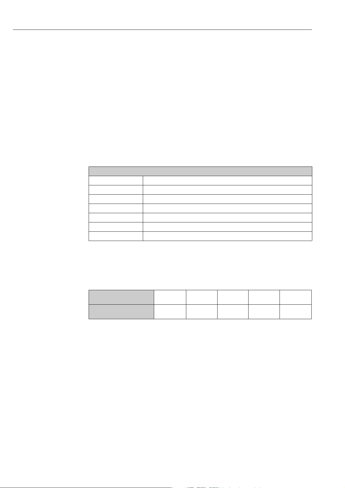
1.1 Document conventions
1.1.1 Safety symbols
Symbol Device particularities and document content
“Caution” indicates an action or procedure which, if not performed correctly, can result
"
#
!
Caution!
Warning!
Note!
in incorrect operation or destruction of the device. Comply strictly with the instructions.
"Warning" indicates an action or procedure which, if not performed correctly, can result
in injury or a safety hazard. Comply strictly with the instructions and proceed with care.
"Note" indicates an action or procedure which, if not performed correctly, can have an
indirect effect on operation or trigger an unexpected response on the part of the device.
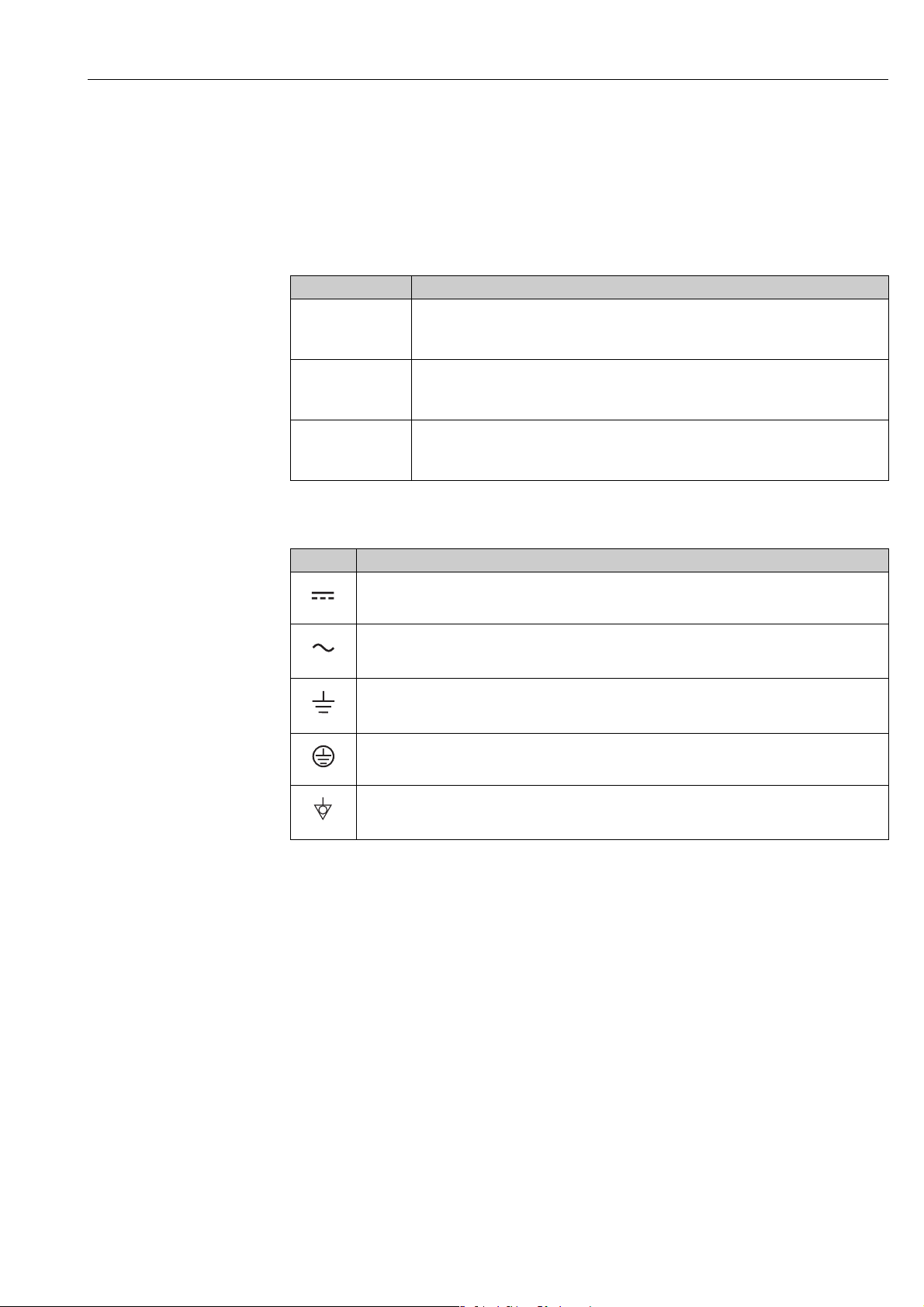
1.1.2 Electrical symbols
Symbol Meaning
Direct current
A terminal at which DC voltage is present or through which direct current flows.
A0011197
Alternating current
A terminal at which alternating voltage (sinusoidal) is present or through which alternating cur-
A0011198
A0011200
A0011199
A0011201
rent flows.
Ground connection
A grounded terminal which, as far as the operator is concerned, is grounded via a grounding system.
Protective ground connection
A terminal which must be connected to ground prior to establishing any other connections.
Equipotential connection
A connection that must be connected to the plant grounding system: This may be a potential
equalization line or a star grounding system depending on national or company codes of practice.
Endress+Hauser 3
Document information Proline t-mass 65 PROFIBUS DP/PA
-
.
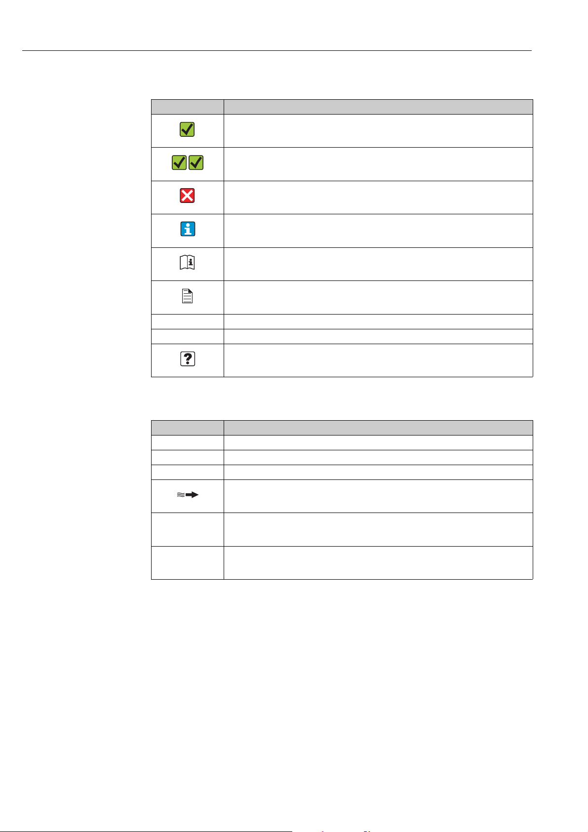
1.1.3 Symbols for types of information
Symbol Meaning
Permitted
Indicates procedures, processes or actions that are permitted.
A0011182
Preferred
Indicates procedures, processes or actions that are preferred.
A0011183
Forbidden
Indicates procedures, processes or actions that are forbidden.
A0011200
Tip
Indicates additional information.
A0011193
Reference to documentation
Refers to the corresponding device documentation.
A0011194
Reference to page
Refers to the corresponding page number.
A0011195
1., 2., 3. etc. Series of steps
Ã
Result of a sequence of actions
Help in the event of a problem
A0013562
1.1.4 Symbols for graphics
Symbol Meaning
1, 2, 3 etc. Item numbers
A, B, C etc. Views
A-A, B-B, C-C etc. Item numbers
Flow direction
A0013441
Hazardous area
Indicates the hazardous area.
A0011187
Safe area (non-hazardous area)
Indicates the non-hazardous area.
A0011187
4 Endress+Hauser

Proline t-mass 65 PROFIBUS DP/PA Safety instructions
2 Safety instructions
2.1 Designated use
The measuring device described in these Operating Instructions is to be used only for
measuring the mass flow rate of gases (e. g. kg, Nm
gas temperature. The measuring device can be configured to measure a standard range of
pure gases or gas mixtures.
Examples:
•Air
•Oxygen
•Nitrogen
• Carbon Dioxide
• Argon, etc.
The use with corrosive, saturated or unclean gases should be treated with caution In such
cases, please contact your Endress+Hauser sales center for clarification. The use with unstable gases or gases not deemed to be suitable by Endress+Hauser must be avoided. The measuring device is not designed to be used with liquids or fluids in the liquid phase.
Resulting from incorrect use or from use other than that designated, the operational safety
of the measuring devices can be jeopardized. The manufacturer accepts no liability for damages being produced from this.
3
sft3). At the same time, it also measures
2.2 Installation, commissioning and operation
Note the following points:
• Installation, connection to the electricity supply, commissioning, operation and maintenance of the measuring device must be carried out by trained, qualified specialists authorized to perform such work by the facility's owner operator. The specialist must have read
and understood these Operating Instructions and must follow the instructions they contain.
• Endress+Hauser is willing to assist in clarifying the chemical resistance properties of parts
wetted by special fluids, including fluids used for cleaning. However small changes in temperature, concentration or the degree of contamination in the process can result in
changes of the chemical resistance properties. Therefore, Endress+Hauser can not guarantee or accept liability for the chemical resistance properties of the fluid wetted materials
in a specific application. The operator is responsible for the choice of fluid wetted materials
in regards to their in-process resistance to corrosion.
• If carrying out welding work on the piping, the welding unit should not be grounded by
means of the measuring device.
• The installer must ensure that the measuring device is correctly wired in accordance with
the wiring diagrams. The transmitter must be grounded unless special protection measures have been taken e.g. galvanically isolated power supply SELV or PELV! (SELV = Safe
Extra Low Voltage; PELV = Protective Extra Low Voltage)
• Invariably, local regulations governing the opening and repair of electrical devices apply.
Endress+Hauser 5

Safety instructions Proline t-mass 65 PROFIBUS DP/PA
2.3 Operational safety
Note the following points:
• Measuring devices for use in hazardous environments are accompanied by separate "Ex
documentation", which is an integral part of these Operating Instructions. Strict compliance with the installation instructions and ratings as stated in this supplementary documentation is mandatory.
The symbol on the front of this supplementary Ex documentation indicates the approval
and the certification body (e.g. 0Europe, 2 USA, 1 Canada).
• Burn hazard! When hot fluid passes through the measuring tube, the surface temperature
of the housing increases. In the case of the sensor, in particular, users should expect temperatures that can be close to the fluid temperature. If the temperature of the fluid is high,
implement sufficient measures to prevent burning or scalding.
• The measuring device complies with the general safety requirements in accordance with
EN 61010-1, the EMC requirements of IEC/EN 61326, and NAMUR recommendation
NE 21, NE 43 and NE 53.
• The separate document on the Pressure Equipment Directive must be observed for measuring devices used in Category II or III installations in accordance with the Pressure Equipment Directive.
• The manufacturer reserves the right to modify technical data without prior notice. Your
Endress+Hauser sales center will supply you with current information and updates to
these Operating Instructions.
2.4 Return
• Do not return a measuring device if it is not absolutely certain that it has been fully cleaned
of all traces of hazardous substances, e.g. substances which have penetrated crevices or
diffused through plastic.
• Costs incurred for waste disposal and injury (burns, etc.) due to inadequate cleaning of the
measuring device will be charged to the owner-operator.
• Refer to the measures on → 109.
2.5 Product safety
This measuring device is designed in accordance with good engineering practice to meet
state-of-the-art safety requirements, has been tested, and left the factory in a condition in
which it is safe to operate. It complies with the applicable standards and regulations in accordance with EN 61010-1 "Safety requirements for electrical equipment for measurement,
control and laboratory use". It can, however, be a source of danger if used incorrectly or for
other than the designated use.
6 Endress+Hauser
Proline t-mass 65 PROFIBUS DP/PA Identification
1
2
3
4
7
8
Order Code:
Ser.No.:
TAG No.:
20-55VAC/16-62VDC
50-60Hz
14VA/8W
IP67/NEMA/Type4X65F25-XXXXXXXXXXXX
12345678901
ABCDEFGHJKLMNPQRST
–20°C (–4°F) < Tamb < +60°C (+140°F)
PROFIBUS DP (Profile 3.0)
Proline t-mass 65
Supply Ext. Termination
i
N12895
BPU S
R O IF
R
5
6
3 Identification
3.1 Device designation
The "t-mass 65" measuring device consists of the following components:
• t-mass 65 transmitter
• t-mass F, t-mass I sensors
Two versions are available:
• Compact version: transmitter and sensor form a single mechanical unit.
• Remote version: transmitter and sensor are installed separately.
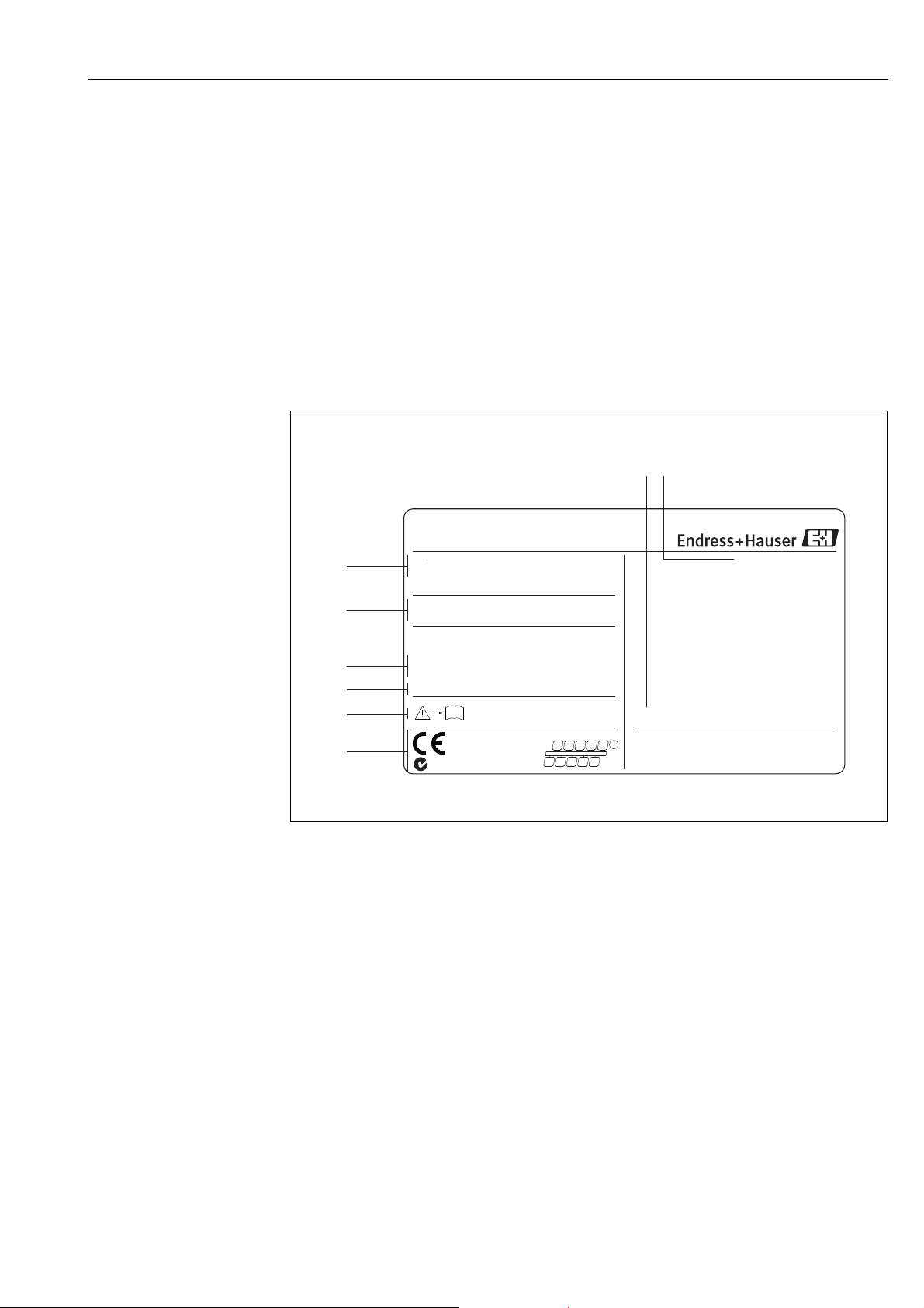
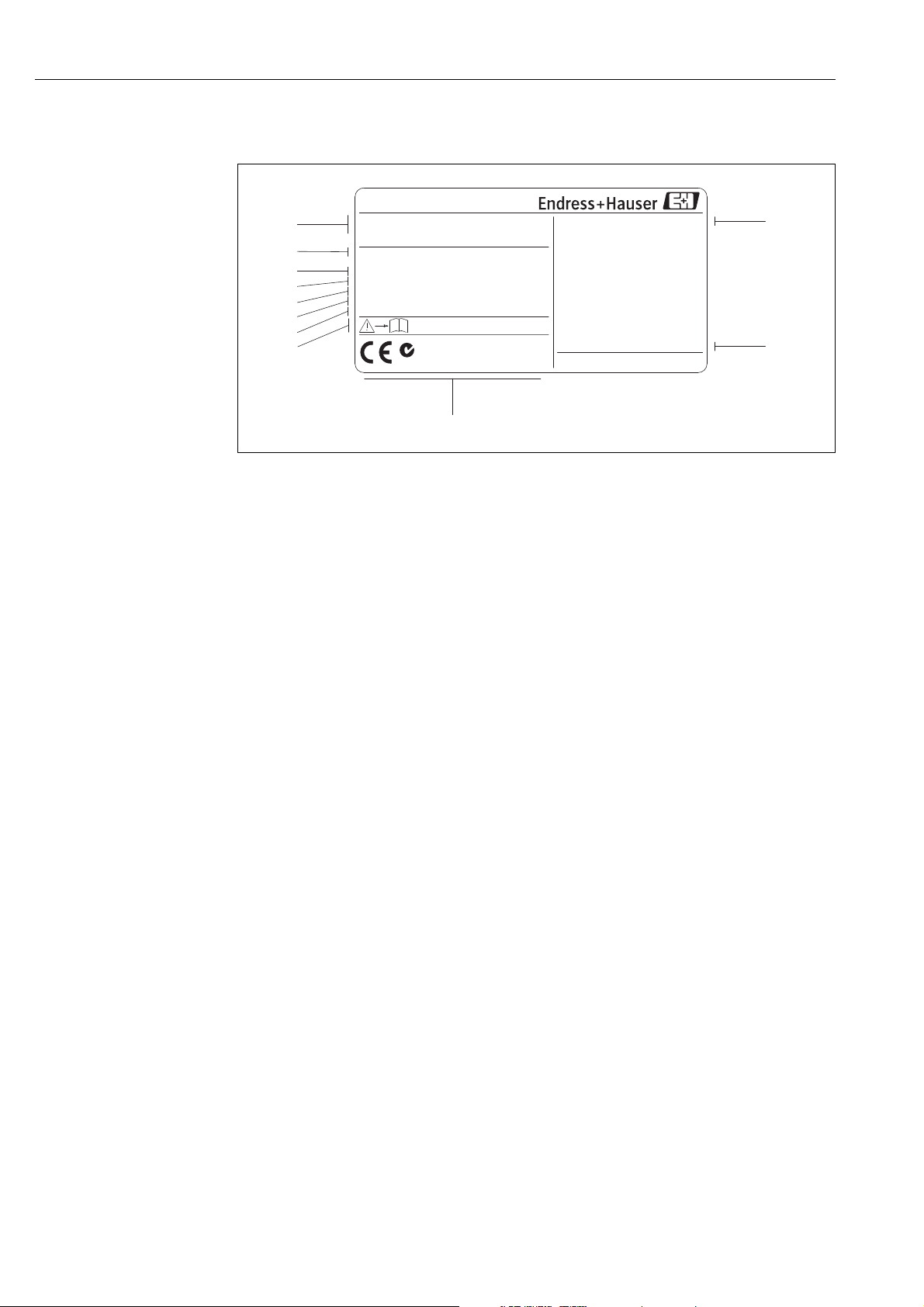
3.1.1 Nameplate of the transmitter
A0005463
Fig. 1: Nameplate specifications for the "t-mass 65" transmitter (example)
1 Order code, serial number: See the specifications on the order confirmation for the meanings of the individual letters and dig-
its.
2 Power supply, frequency, power consumption
3 Available inputs/outputs:
4 Reserved for information on special products
5 Please refer to measuring device documentation
6 Reserved for certificates, approvals and for additional information on device version
7 Ambient temperature range
8 Degree of protection
Endress+Hauser 7
Identification Proline t-mass 65 PROFIBUS DP/PA
1
2
4
5
6
7
9
11
10
3
Proline t-mass F
ABCDEFGHIJKLMNOPQRST
TAG-No.:
Ser.No.:
12345678901
Order Code:
IP67 / NEMA/Type 4X
65F50-XXXXXXXXXXXX
P:
T:
Materials:
Seal:
3.1
-0.5...40bar /-7.25...+580 psi gauge
EPDM / PEEK
316/316L/1.4404/Alloy C 22- (2.4602)
-40°C...+100°C /-40°F...+212°F
-20°C(-4°F) <Tamb< +60°C(+140°F)
i
DN50 DIN/EN PN40
N12895
8
3.1.2 Nameplate of the sensor
A0005512
Fig. 2: Nameplate specifications for the "t-mass F" sensor (example)
1 Order code, serial number: See the specifications on the order confirmation for the meanings of the individual letters and dig-
its.
2 Nominal diameter device
3 Pressure range
4 Temperature range
5 Material of measuring tubes
6Seal material
7 Reserved for information on special products
8 Please refer to measuring device documentation
9 Ambient temperature range
10 Degree of protection
11 Reserved for additional information on device version (approvals, certificates)
8 Endress+Hauser
Proline t-mass 65 PROFIBUS DP/PA Identification
2
3
1
4
5
6
7
8
9
10
Device SW:
01.Dec 2009
XXXXXXXXXXXXXXXXXX
Drivers:
Communication:
Date:
SW-versionEx-works
See Operating manual
Betriebsanleitung beachten
Observer Manuel d'Instruction
N / L-
PE
L1 / L+
1 2
319475-0011
20(+)/21(-)
22(+)/23(-)
24(+)/25(-)
26(+)/27(-)
NC:
NO:
P:
A:
Tension d'alimentation
Versorgung /
Supply /
12345678912Ser. No.:
normally open contact
normally closed contact
passive
active
Update 2
PROFIBUS DP (Profile 3.0)
XX.XX.XX
27 = A (RxD/TxD-N)
26 = B (RxD/TxD-P)
Supply Ext. Termination
25 = DGND
24 = +5V
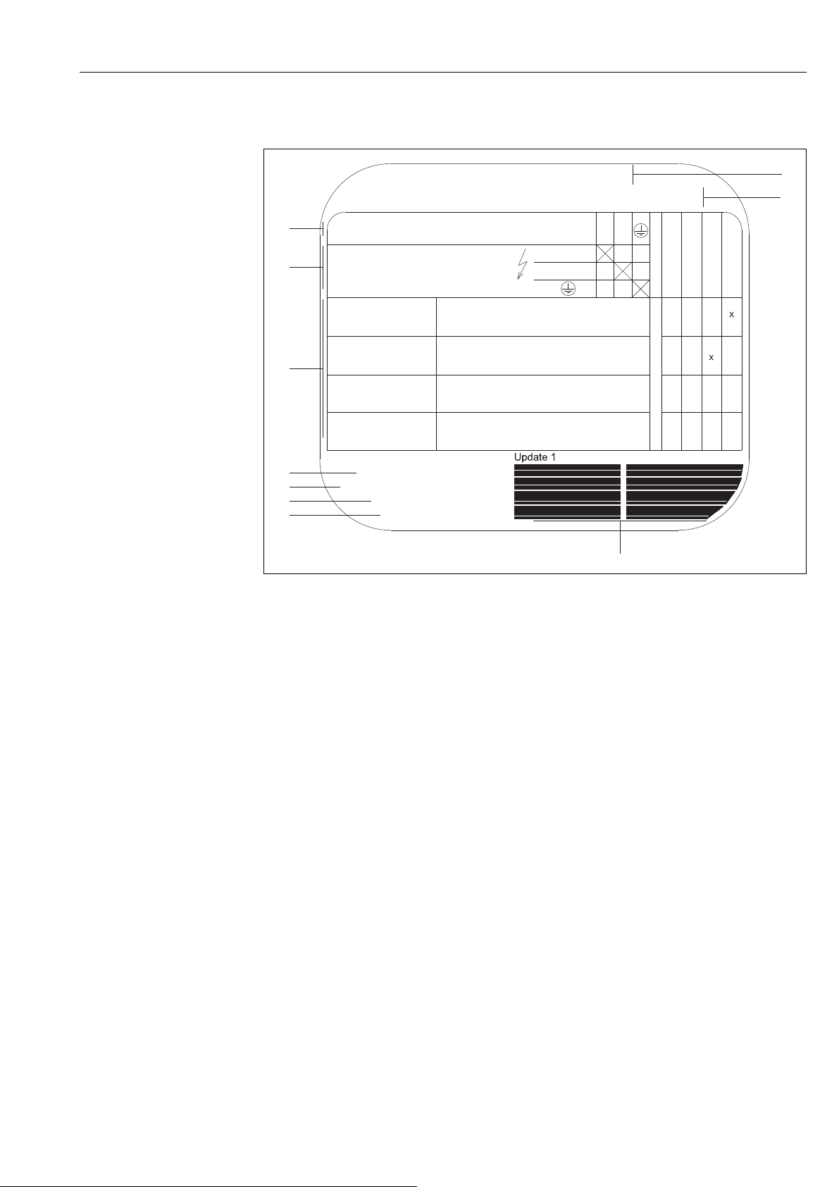
3.1.3 Nameplate for connections
A005464
Fig. 3: Nameplate specifications for transmitter connections (example)
1 Serial number
2 Possible configuration of current output
3 Possible configuration of relay contacts
4 Terminal assignment, cable for power supply: 85 to 260 V AC, 20 to 55 V AC, 16 to 62 V DC
Terminal No. 1: L1 for AC, L+ for DC
Terminal No. 2: N for AC, L– for DC
5 Signals present at inputs and outputs, possible configuration and terminal assignment (20 to 27),
see also "Electrical values of inputs/outputs", → 111
6 Version of measuring device software currently installed
7 Installed communication type, e.g.: HART, PROFIBUS DP, etc.
8 Information on current communication software (Device Revision and Device Description),
e.g.: Dev. 01 / DD 01 for HART
9Date of manufacture
10 Current updates to data specified in points 6 to 9
Endress+Hauser 9

Identification Proline t-mass 65 PROFIBUS DP/PA
3.2 Certificates and approvals
This measuring device is designed in accordance with good engineering practice to meet
state-of-the-art safety requirements, has been tested, and left the factory in a condition in
which it is safe to operate. The measuring device complies with the applicable standards and
regulations in accordance with EN 61010-1 "Safety requirements for electrical equipment
for measurement, control and laboratory use" and with the EMC requirements of IEC/EN
61326.
The measuring device described in these Operating Instructions thus complies with the statutory requirements of the EC Directives. Endress+Hauser confirms successful testing of the
measuring device by affixing to it the CE mark.
The measuring device meets the EMC requirements of the Australian Communications and
Media Authority (ACMA).
The flow measuring system has successfully passed all the test procedures carried out and is
certified and registered by the PNO (PROFIBUS User Organization).
The device thus meets all the requirements of the following specifications:
• Certified to PROFIBUS Specification, Profile Version 3.0
Device certification number: available on request
• The device can also be operated in conjunction with other-make certified devices
(interoperability).
3.3 Registered trademarks
KALREZ® and VITON
Registered trademarks of DuPont Performance Elastomers L.L.C., Wilmington, USA
PROFIBUS
®
Registered trademark of the PROFIBUS User Organization, Karlsruhe, Germany
HistoROM™, S-DAT
Registered or registration-pending trademarks of businesses in the Endress+Hauser Group
®
®
, T-DAT™, F-CHIP®, FieldCare®, FieldCheck®, Applicator®, t-mass
®
10 Endress+Hauser
Proline t-mass 65 PROFIBUS DP/PA Installation
4Installation
4.1 Incoming acceptance, transport and storage
4.1.1 Incoming acceptance
On receipt of the goods, check the following points:
• Is the packaging or content undamaged?
• Is the delivery complete and do the delivered goods match your order?
4.1.2 Transport
Observe the following instructions when unpacking and transporting the device to its final
location:
• Transport the measuring device in the container in which it is delivered.
• The covers or caps fitted to the process connections prevent mechanical damage to the
sealing surfaces and contamination in the measuring tube when the unit is being transported or in storage. Do not remove these covers or caps until immediately before installation.
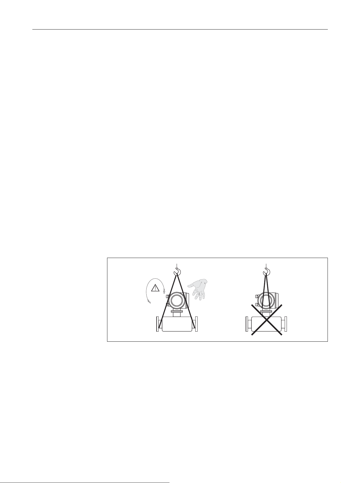
• Do not lift measuring devices of nominal diameters > DN 40 (1½") by the transmitter housing or the connection housing in the case of the remote version → 4. For transportation
purposes, use webbing slings slung round the two process connections. Do not use chains,
as they could damage the housing.
#
Warning!
Risk of injury if the measuring device slips. The center of gravity of the assembled measuring
device might be higher than the points around which the slings are slung.
When transporting, make sure that the measuring device does not unexpectedly turn
around its axis or slip.
A0004294
Fig. 4: Instructions for transporting sensors with > DN 40 (> 1½")
4.1.3 Storage
Note the following points:
• Pack the measuring device in such a way as to protect it reliably against impact for storage
(and transportation). The original packaging provides optimum protection.
• The permissible storage temperature is: –40 to +80 °C (–40 to +176 °F),
preferably +20 °C (+68 °F).
• Do not remove the protective covers or caps on the process connections until you are ready
to install the device.
• The measuring device must be protected against direct sunlight during storage in order to
avoid unacceptably high surface temperatures.
• Devices delivered with special sealing or bagging for oxygen service must remain sealed or
bagged until ready for installation.
Endress+Hauser 11

Installation Proline t-mass 65 PROFIBUS DP/PA
4.2 Installation conditions
Note the following points:
• The thermal dispersion principle is very sensitive to disturbed flow conditions.
• Observe the recommended inlet and outlet requirements.
• Good engineering practice is necessary for the associated pipe work and installation.
• Ensure correct alignment and orientation of the sensor.
• Take measures to reduce or avoid condensation (e.g. install a condensation trap, thermal
insulation, etc.).
• The maximum permitted ambient temperatures → 116 and the medium temperature
range → 116 must be observed.
• Install the transmitter in a shaded location or use a protective sun shield.
• For mechanical reasons, and in order to protect the pipe, it is advisable to support heavy
sensors.
4.2.1 Dimensions
The dimensions and installation lengths of the sensor and transmitter can be found in the
"Technical Information" for the device in question. This document can be downloaded as a
PDF file from www.endress.com. A list of the "Technical Information" documents available
can be found in the "Documentation" section on → 122.
4.2.2 System pressure and pulsating flow
Reciprocating pumps and some compressor systems can create strong changes in process
pressure that can induce spurious internal flow patterns and therefore cause additional measurement error. These pressure pulses must be reduced by the appropriate measures:
• Use of expansion tanks
• Use of inlet expanders
• Relocate the flowmeter further downstream
In compressed air systems, it is recommended to mount the flowmeter after the filter, dryer
and buffer devices to avoid pulsations and oil/dirt contamination.
Do not mount the flowmeter directly after the compressor outlet.
12 Endress+Hauser
Proline t-mass 65 PROFIBUS DP/PA Installation
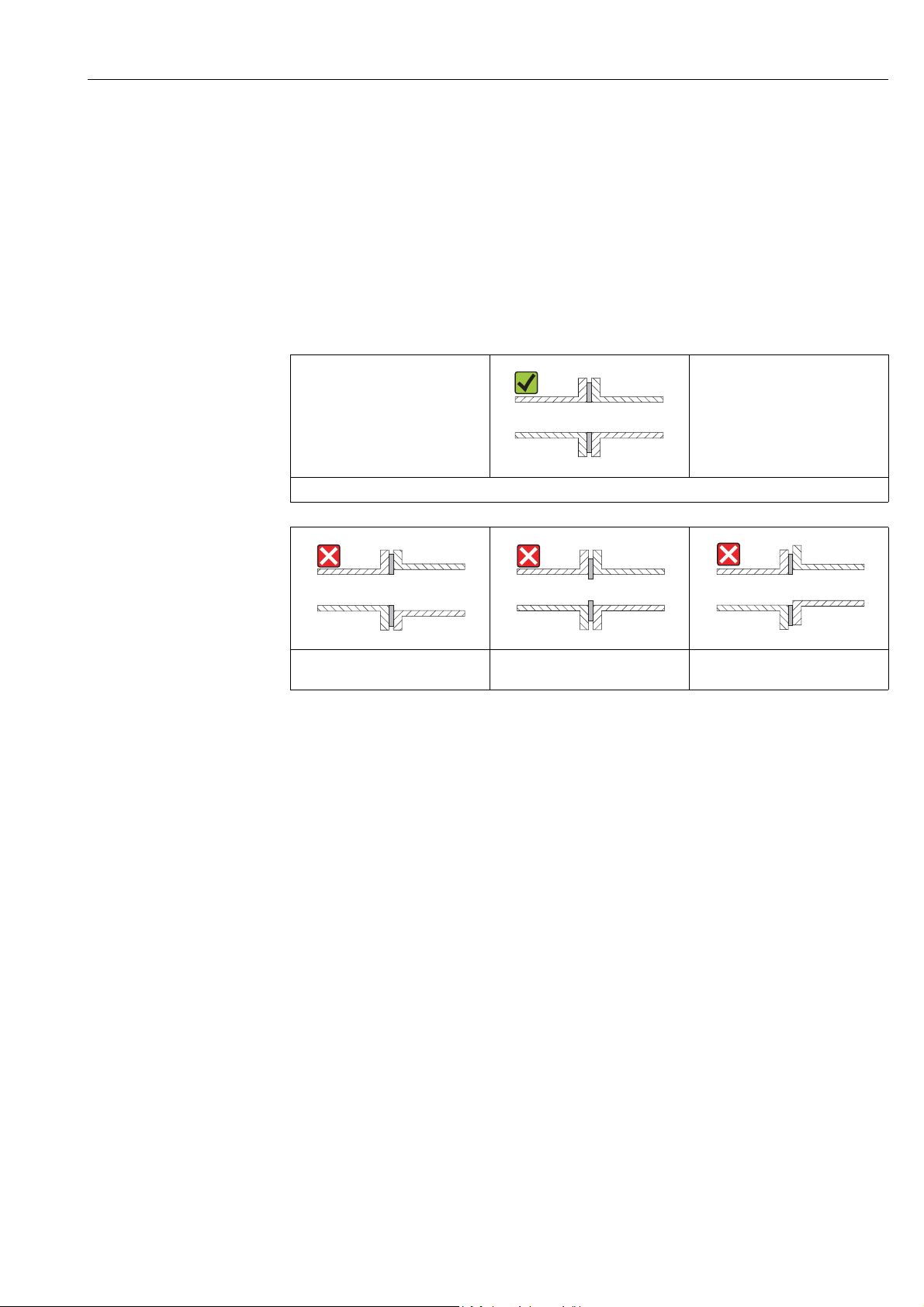
4.2.3 Pipework requirements
Good engineering practice should be followed at all times:
• Correct preparation, welding and finishing techniques
• Correctly sized gaskets
• Correctly aligned flanges and gaskets
• Connecting pipe work should match the internal diameter of the flowmeter. Maximum
pipe diameter mismatch should not exceed:
– 1 mm (0.04 in) for diameters < DN 200 (8")
– 3 mm (0.12 in) for diameters DN 200 (8")
Further information is provided in ISO Standard 14511.
A0005103
Correctly aligned flanges and gaskets
A0005104 A0005105 A0005106
Pipe diameter one is not equal pipe
diameter two
Caution!
"
New installations should be free of metallic and abrasive particles to prevent damage to the
Incorrectly sized gaskets Incorrectly aligned flanges and gas-
kets
sensing elements on start-up.
Endress+Hauser 13
Installation Proline t-mass 65 PROFIBUS DP/PA
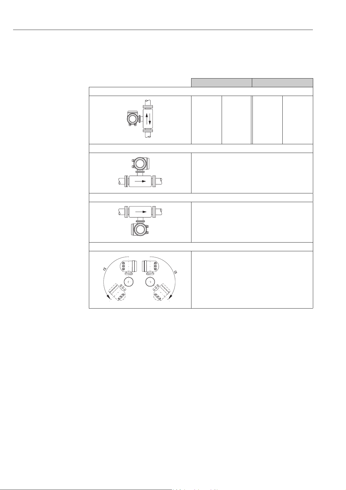
4.2.4 Orientation
Make sure that the direction arrow on the sensor matches the direction of flow through the
pipe.
Flanged sensor Insertion sensor
Vertical orientation
compact
remote
compact
remote
A0013785
Horizontal orientation, transmitter head up
A0013786
Horizontal orientation, transmitter head down
A0013787
Inclined orientation, transmitter head down
m
m
compact/remote
n
compact/remote
o
compact/remote
p
m, n
m
A0009897
= Recommended orientation
= Orientation recommended in certain situations
In the case of saturated or unclean gases, upward flow in a vertical pipe section is preferred to minimize con-
m
densation/contamination.
Not recommended if the vibrations are too high or if the installation is unstable.
n
Only suitable for clean/dry gases. Do not mount the sensor from the bottom, on horizontal pipes, if build-up
o
or condensate are likely to be present. Mount the sensor in a position as indicated below
If the gas is very wet or saturated with water (e. g. biogas, undried compressed air), mount in inclined orien-
p
tation (approx. 135° ±10°).
14 Endress+Hauser
Proline t-mass 65 PROFIBUS DP/PA Installation
15xDN 2xDN
15xDN
2xDN
15xDN
2xDN
20xDN
2xDN
35xDN
2xDN
50xDN
2xDN
20xDN 5xDN
20xDN 5xDN
20xDN 5xDN
25xDN 5xDN
40xDN 5xDN
50xDN 5xDN
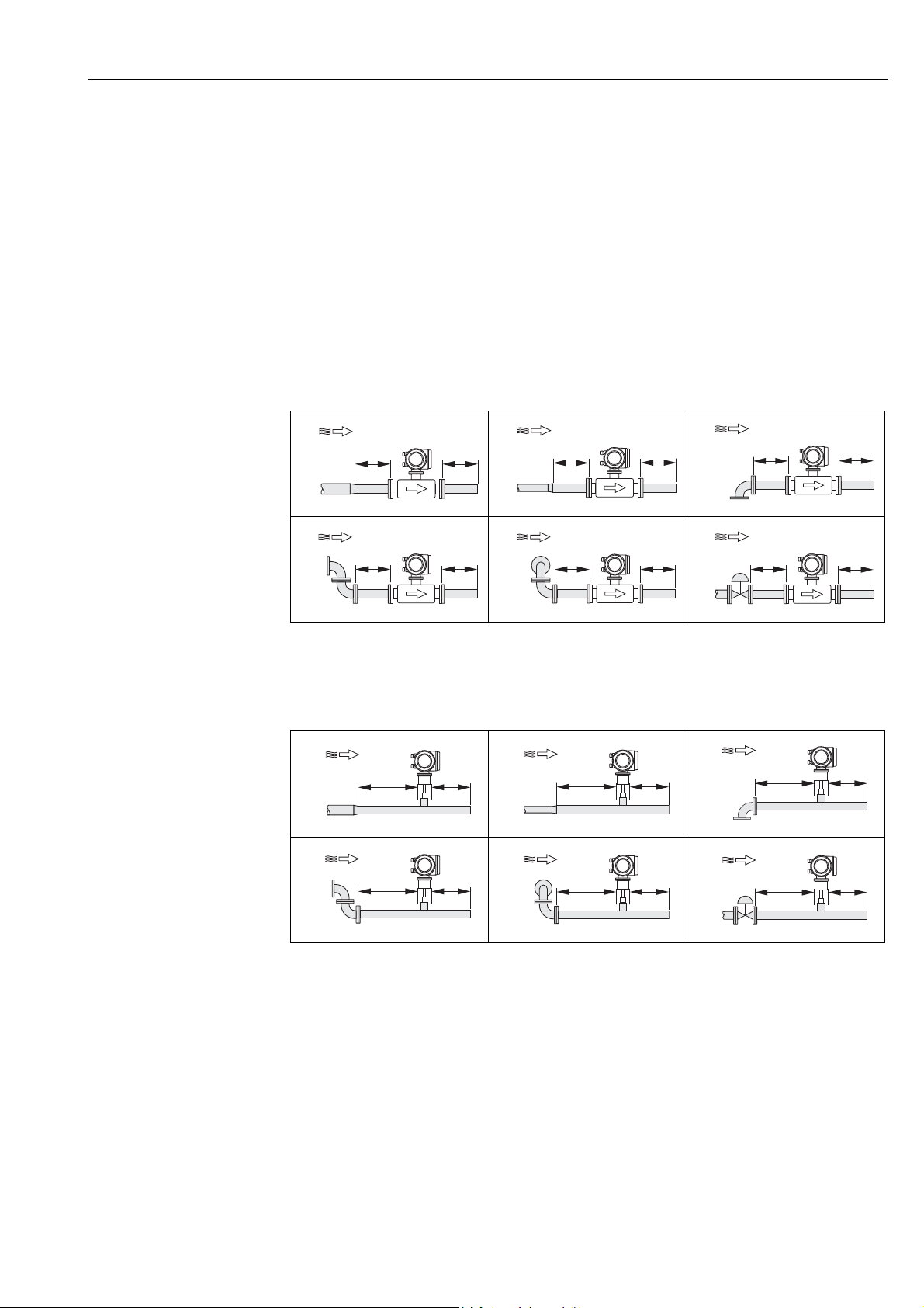
4.2.5 Inlet and outlet runs
The thermal dispersion principle is sensitive to disturbed flow conditions.
As a general rule, the thermal flowmeter should always be installed as far away as possible
from any flow disturbances. For further information ISO Standard 14511.
!
Note!
• Where two or more flow disturbances are located upstream of the meter, the longest indicated inlet length should prevail. For example if a control valve is additionally mounted
upstream from the measuring device and an elbow on the inlet side, select the recommended inlet length for control valves: 50 × DN
• For very light gases such as Helium and Hydrogen all upstream distances should be doubled.
The minimum recommendations for inlet and outlet runs (without flow conditioner) are:
Flanged sensor
1
4
1 = Reduction, 2 = Expansion, 3 = 90° elbow or T-piece, 4 = 2 × 90° elbow,
5 = 2 × 90° elbow (3-dimensional), 6 = Control valve
A0007523
A0007526
2
A0007524
5
A0007527
Insertion sensor
1
4
A0007529
2
A0007530
5
3
A0007525
6
A0007528
3
A0007531
6
Endress+Hauser 15
!
A0007532
1 = Reduction, 2 = Expansion, 3 = 90° elbow or T-piece, 4 = 2 × 90° elbow,
5 = 2 × 90° elbow (3-dimensional), 6 = Control valve or pressure regulator
A0007564
A0007534
Note!
A specially designed perforated plate flow conditioner can be installed if it is not possible to
observe the inlet runs required (→ 16).
Installation Proline t-mass 65 PROFIBUS DP/PA
PT
2...5 x DN
2 × DN5 - 10 × DN
>8 × DN 5 × DN
5 - 10 × DN
2
1
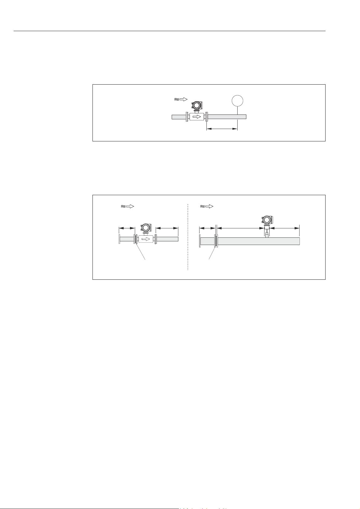
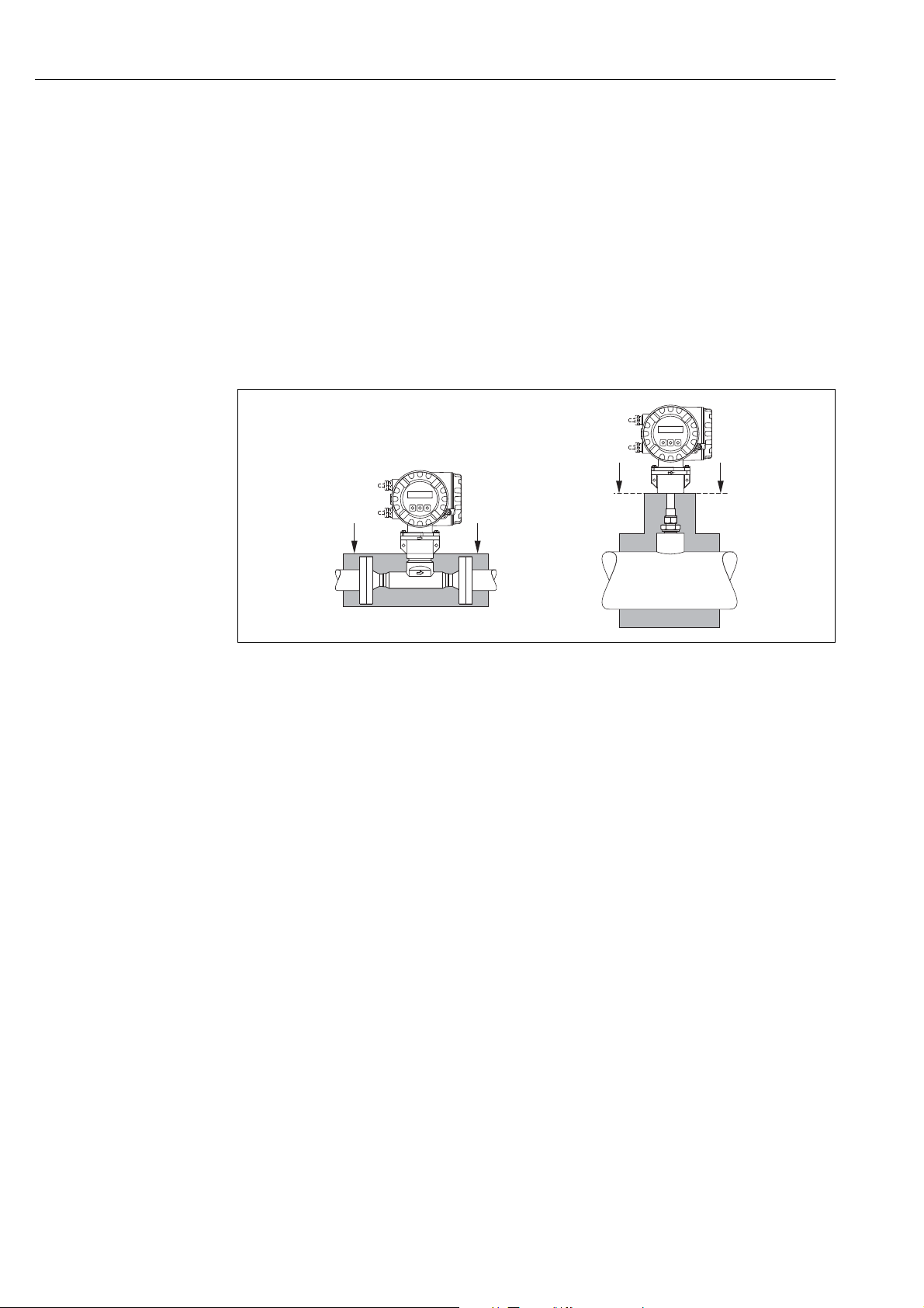
Outlet runs with pressure measuring points
The pressure measuring point should be installed downstream of the measuring device, so
that there is no potential influence of the pressure transmitter process connection on the
flow entering the measuring point.
A0005114
Fig. 5: Installing a pressure measuring point (PT = pressure transmitter)
Perforated plate flow conditioner
It is recommended to install a perforated plate flow conditioner if the recommended inlet
runs are not available.
!
A0005115
Fig. 6: The figure above illustrates the minimum recommended inlet and outlet runs expressed in multiples of the pipe diameter
1 = Flow conditioner with the flanged sensor, 2 = Flow conditioner with the insertion sensor
using a flow conditioner.
Flow conditioner for use with insertion sensors 65I
→ 90
The well known "Mitsubishi" design is recommended for this application DN 80 mm to
DN 300 mm (3" to 12"). The flow conditioner must be installed at a distance of 8 × DN
upstream of the sensor. A further 5 pipe diameters minimum inlet run is required upstream
of the actual conditioner itself.
Measured errors can occur depending on disturbances in the inlet run. Therefore it is advisable to choose inlet runs that are as long as possible.
Note!
In the case of insertion devices, the inlet run selected downstream of the conditioner should
be as long as possible.
16 Endress+Hauser
Proline t-mass 65 PROFIBUS DP/PA Installation
1
2
2
3
4
1
1
1
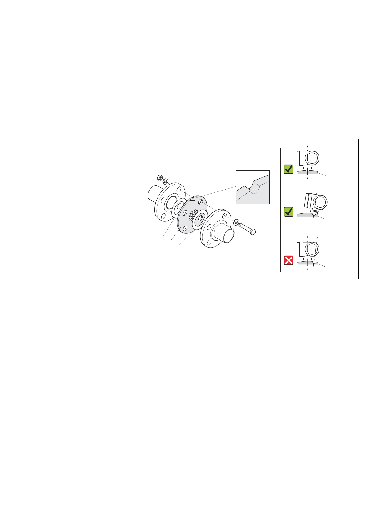
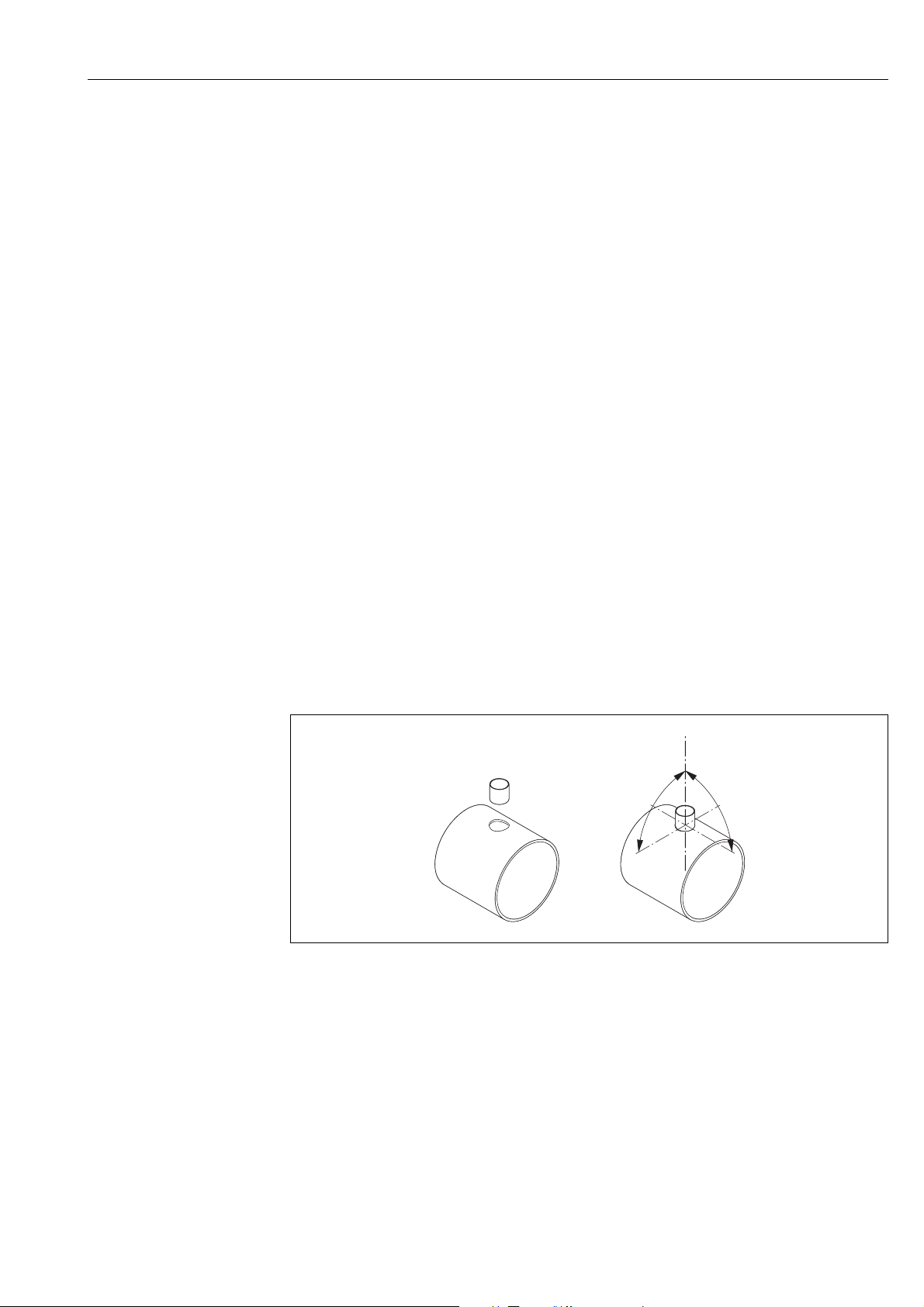
Perforated plate flow conditioners (19 hole) for use with flanged sensor 65F → 90
This is a special Endress+Hauser version designed especially for use with the t-mass F sensor
(sizes DN 25 to 100 / 1" to 4"). The mounting hole patterns and sizing are of a multi-variant
design which means that one plate will fit different flange pressure classes e.g. Cl. 150 and
Cl. 300.
The flow conditioner and gaskets are fitted between the pipe flange and the measuring
device → 7. Use only standard bolts which match the flange bolt hole to guarantee that
the flow conditioner is centered correctly.
The alignment notch must also be pointing in the same plane as the transmitter. Incorrect
installation of the flow conditioner will have a small effect on the measurement accuracy.
A0005116
Fig. 7: Flow conditioner mounting arrangement (example)
1=perforated plate flow conditioner, 2= aeal/gasket, 3= alignment notch, 4 = alignment in the same plane as the transmitter
Note
• Order the t-mass F sensor and the flow conditioner together to ensure that they are calibrated together. Joint calibration guarantees optimum performance. Ordering the flow
conditioner separately and using it with the measuring device will further increase measurement uncertainty.
• The use of conditioners from other suppliers will affect the flow profile and pressure drop
and will have an adverse effect on performance.
• Bolts, nuts, seals, etc. are not included in the scope of supply and must be supplied by the
customer.
Endress+Hauser 17
Installation Proline t-mass 65 PROFIBUS DP/PA
aa
bb
4.2.6 Heating
Some applications require suitable measures to avoid heat loss (condensation). Heating can
be electric, e. g. with heated elements, or by means of hot water, steam pipes or insulation.
Caution!
"
Risk of electronics overheating! Consequently, make sure that the adapter between sensor
and transmitter and the connection housing of the remote version always remain free of
insulating material.
4.2.7 Thermal insulation
When the gas is very damp or saturated with water (e. g. bio gas), the piping and flowmeter
body should be insulated to prevent water droplets condensing on the measuring sensor.
Fig. 8: Maximum thermal insulation for t-mass 65F and 65I
a Maximum insulation height for the flanged sensor
b Maximum insulation height for the insertion sensor
4.2.8 Vibrations
Caution!
"
Excessive vibration can result in mechanical damage to the measuring device and its mounting.
Observe the vibration spezification in the technical data section → 116
A0005122
18 Endress+Hauser
Proline t-mass 65 PROFIBUS DP/PA Installation
90°
90°
4.3 Installation
4.3.1 Mounting the insertion sensor
The sensor can be mounted into a welding socket or a retractable mounting set. If a retractable mounting set is being used, then refer to the supplementary documentation delivered
with the mounting set.
Mounting the welding socket
This instruction describes mounting of the Endress+Hauser welding socket. If a welding boss
is already available or a customer-specific one is being used, then go to the next section
"Insertion depth calculation and adjustment."
!
"
#
Note!
• Take the orientation and inlet and outlet runs into account before mounting the welding
socket→ 14 ff.
• The welding socket is made of stainless steel 1.4404 (316/316L). Use appropriate welding technique.
Caution!
• When mounting the fitting to a thin wall duct, use a suitable support bracket for the sensor
and weld the welding socket to a base plate to spread the load. Otherwise, the mounting
may be unstable and the duct wall can be damaged.
Warning!
• These instructions are only applicable to installation in an un-pressurized line, without gas
present and at safe temperatures.
1. Drill or a cut hole of Ø 31.0 mm ± 0.5 mm (1.22 ± 0.019") in the pipe.
2. Deburr the hole.
3. Fit the edge of the welding socket into hole, align it vertically and weld it on → 9.
A0010098
Fig. 9: Positioning the welding socket on the pipe (or duct)
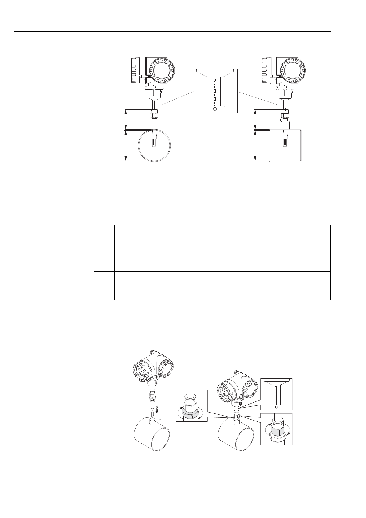
Insertion depth calculation and adjustment
To ensure optimum measurement performance, the insertion sensor must be installed in the
correct position in the pipe or duct (30% of the internal diameter).
A millimeter and inch scale is provided along the entire length of the sensor tube. This
makes it possible to align the sensor at the right depth.
4. Calculate the insertion depth:
– with the help of the Quick Setup "Sensor" → 52 or
Endress+Hauser 19
– using the following dimensions and formulae
Installation Proline t-mass 65 PROFIBUS DP/PA
A
B
C
A
B
C
230
220
210
200
190
180
9
8
7
230
220
210
200
190
180
9
8
7
230
220
210
200
190
180
9
8
7
1
3
4
2
230
220
210
200
190
180
9
8
7
A0005118
Fig. 10: Dimensions needed to calculate the insertion depth
A Pipes: internal diameter
Ducts: internal dimension
B Wall thickness
C Dimension from pipe/duct to the compression fitting
!
The following dimensions are required to calculate the insertion depth:
A • For circular pipes: the internal diameter (DN)
B Pipe / duct wall thickness
C Height of the welding nozzle at the pipe/duct including the sensor compression fitting or low pressure
• For rectangular ducts:
– The internal duct height if the sensor is installed vertically
– The internal duct width if the sensor is installed horizontally
Note!
!
Minimum length of dimension A = 80 mm (3.15 in)
mounting set (if used).
Note!
For detailed remarks on calculation refer to Technical Information TI00069D.
• Calculated insertion depth = (0.3 × A) + B + C + 2 mm (0.08 in)
Note down the calculated value.
Fig. 11: Aligning the sensor to the calculated insertion depth
20 Endress+Hauser
A0010001
Proline t-mass 65 PROFIBUS DP/PA Installation
90°±7°
90°±3°
B
A
1
2
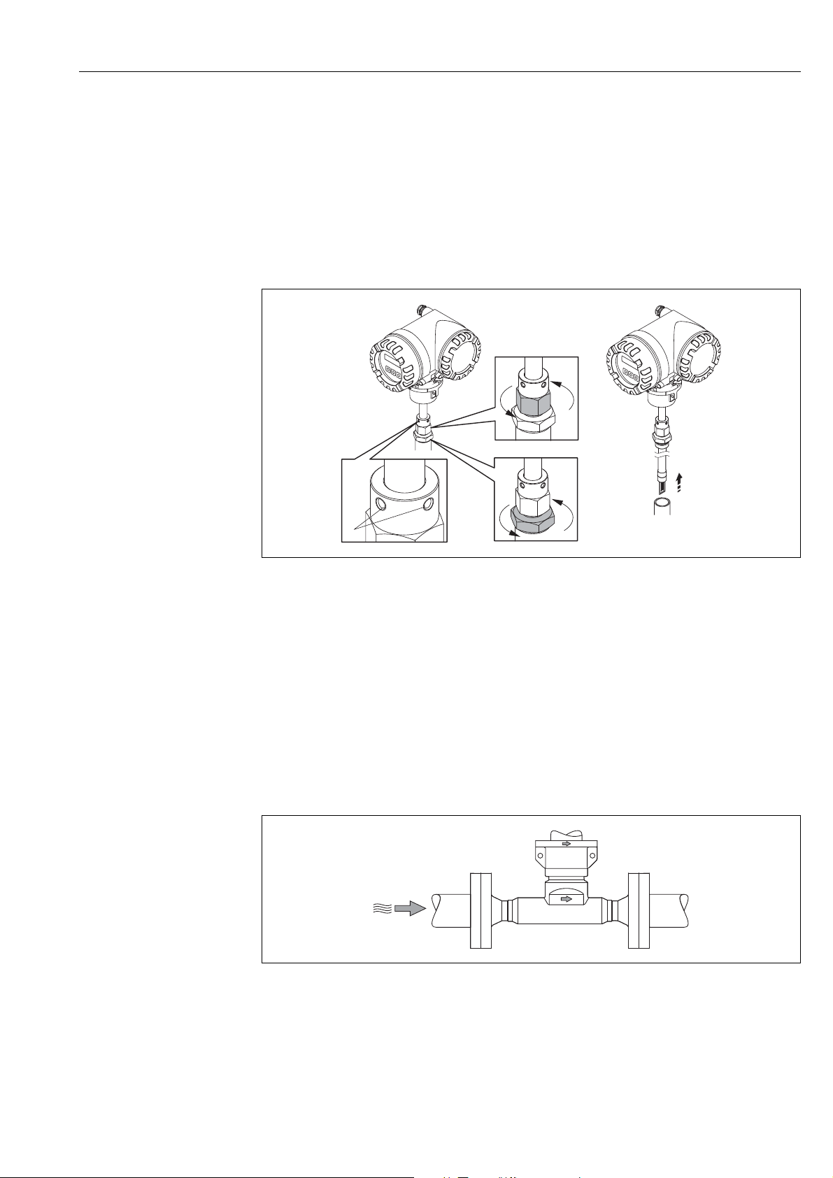
5. Insert the sensor in the nozzle (1) and tighten the lower nut of the compression fitting
(2) finger-tight.
Caution!
"
– NPT thread: use a thread sealing tape or paste
– G 1 A thread: the sealing ring supplied must be installed
6. Tighten the upper nut of compression fitting (3) such that the sensor can still be
adjusted.
7. Read off the calculated insertion depth from the scale and adjust the sensor so that the
value aligns with the upper end of the compression fitting (4).
8. Tighten the lower nut of the compression fitting 1¼ revolutions using a wrench (42
mm).
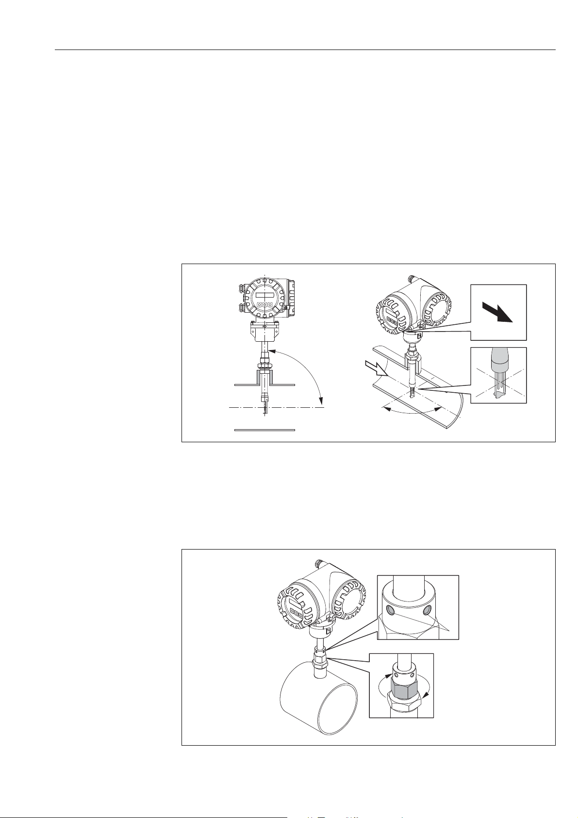
Aligning the sensor with the flow direction
A0005117
Fig. 12: Aligning the sensor with the flow direction
9. Check and ensure that the sensor is aligned vertically at a 90° angle on the pipe/duct.
Turn the sensor so that the arrow marking matches the direction of flow.
!
Note!
To ensure optimum exposure of the measuring transducer to the flowing gas stream, the
sensor must not be rotated more than 7° from this alignment.
Fig. 13: Securing the position of the sensor
A0010114
Endress+Hauser 21

Installation Proline t-mass 65 PROFIBUS DP/PA
10. Tighten the compression fitting (1) by hand to secure the position of the sensor. Then,
using an open-ended wrench, tighten another 1¼ revolutions in a clockwise direction.
11. Fix the two securing screws (2) (Allen key 3 mm; (1/8")).
Warning!
#
Observe torque: 4 Nm (2.95 lbf ft)
12. Check that the sensor and transmitter do not turn.
13. Check the measuring point for leaks at the maximum operating pressure.
22 Endress+Hauser
Proline t-mass 65 PROFIBUS DP/PA Installation
1
2
3
4.3.2 Removing the insertion sensor
#
Warning!
• Do not remove the measuring device when it is pressurized! Stop the gas flow and unpressurize the process pipe.
• In the case of toxic, explosive or flammable gases, the pipe in which the measuring device
is installed must be purged with an inert gas to remove all traces of the gas used.
• Make sure that the process cannot be resumed while removal work is in progress.
• Allow the system and device to cool to a safe temperature
(i.e. <50 °C, (<120 ° F)).
A0011016
Fig. 14: Removing the insertion sensor
1. Release the securing screws (1).
2. Release the upper nut of compression fitting using a wrench, turning in a counterclock-
wise direction (2).
Caution!
"
In the case of vertical installation, do not drop the measuring device into the pipe.
3. Unscrew the lower nut of compression fitting (3) and remove the sensor.
4.3.3 Mounting the flanged sensor
The arrow on the sensor must match with the actual direction of flow through the pipe.
A0013663
Fig. 15: Mounting in direction of flow
Endress+Hauser 23
Installation Proline t-mass 65 PROFIBUS DP/PA
3
5
6
1
2
4
4 x 45°
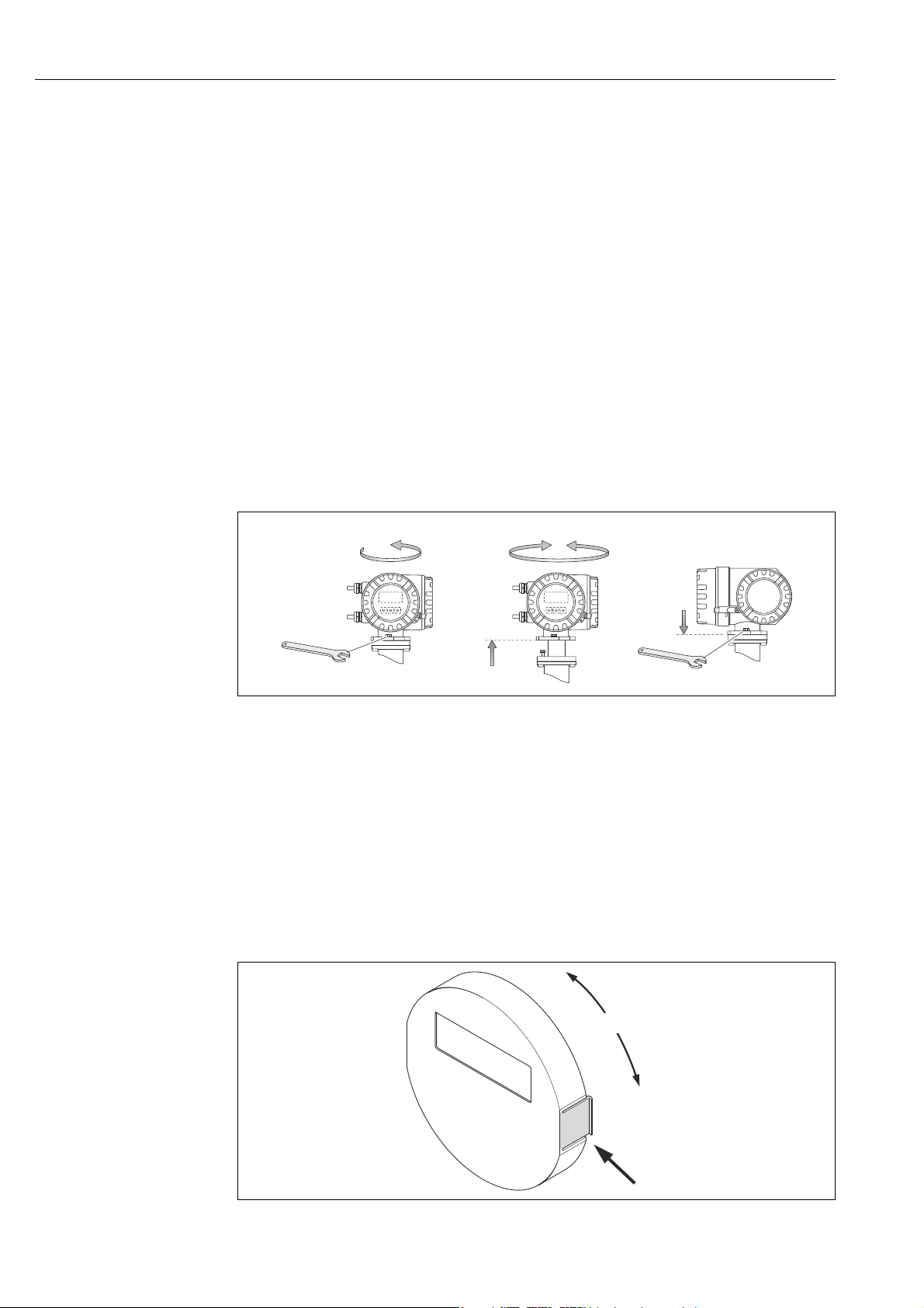
4.3.4 Turning the transmitter housing
Turning the aluminium field housing
#
Warning!
The rotating mechanism for measuring devices for hazardous areas Zone 1 (ATEX/IEC Ex)
or Clas s I Div . 1 ( FM/C SA) is dif fere nt to that described here. The procedure for turning these
housings is described in the Ex-specific documentation → 122.
1. Loosen the two securing screws.
Caution!
"
Special screw! Do not loosen screw completely or replace with another screw.
Use only original Endress+Hauser parts.
1. Turn the bayonet catch as far as it will go.
2. Carefully lift the transmitter housing as far as it will go.
3. Turn the transmitter housing to the desired position (max. 2 × 90° in either direction).
4. Lower the housing into position and re-engage the bayonet catch.
5. Retighten the two securing screws.
A0004302
Fig. 16: Turning the transmitter housing (aluminium field housing)
4.3.5 Turning the local display
1. Unscrew cover of the electronics compartment from the transmitter housing.
2. Press the side latches on the display module and remove the module from the electronics compartment cover plate.
3. Rotate the display to the desired position (4 × 45 ° in both directions), and reset it onto
the electronics compartment cover plate.
4. Screw the cover of the electronics compartment firmly back onto the transmitter housing.
Fig. 17: Turning the local display (field housing)
24 Endress+Hauser
A0003236
Proline t-mass 65 PROFIBUS DP/PA Installation
a
b
c
90 (3.54)
35 (1.38)
192 (7.56)
81.5 (3.2)
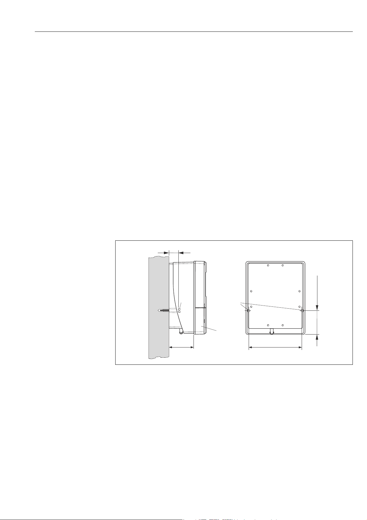
4.3.6 Installing the wall-mount transmitter housing
There are various ways of installing the wall-mount transmitter housing:
• Mounted directly on the wall
• Installation in control panel → 26 (separate mounting set, accessories → 90)
•Pipe mounting → 26 (separate mounting set, accessories → 90)
Caution!
"
• The ambient temperature may not exceed the permissible range of –20 to +60 °C (–4 to
+140 °F), optionally
–40 to +60 °C (–40 to +140 °F), at the mounting location.
• Install the device in a shady location. Avoid direct sunlight on the display.
• Always install the wall-mount housing in such a way that the cable entries are pointing
down.
Mounted directly on the wall
1. Drill the holes as illustrated in the diagram.
2. Remove the cover of the connection compartment (a).
3. Push the two securing screws (b) through the appropriate bores (c) in the housing.
– Securing screws (M6): max. Ø 6.5 mm (0.26 inch)
– Screw head: max. Ø 10.5 mm (0.41 inch)
4. Secure the transmitter housing to the wall as indicated.
5. Screw the cover of the connection compartment (a) firmly onto the housing.
Fig. 18: Engineering unit mm (in)
A0001130
Endress+Hauser 25
Installation Proline t-mass 65 PROFIBUS DP/PA
245 (9.65)
~110 (~4.33)
210 (8.27)
+0.5 (+0.019)
–0.5 (–0.019)
+0.5 (+0.019)
–0.5 (–0.019)
Ø 20…70
(Ø 0.79…2.75)
~ ~ 6.1)155 (
Installation in control panel
1. Prepare the opening in the panel as illustrated in the diagram.
2. Slide the housing into the opening in the panel from the front.
3. Screw the fasteners onto the wall-mount housing.
4. Screw threaded rods into holders and tighten
until the housing is solidly seated on the panel wall. Afterwards, tighten the locking
nuts.
Additional support is not necessary.
Fig. 19: Engineering unit mm (in)
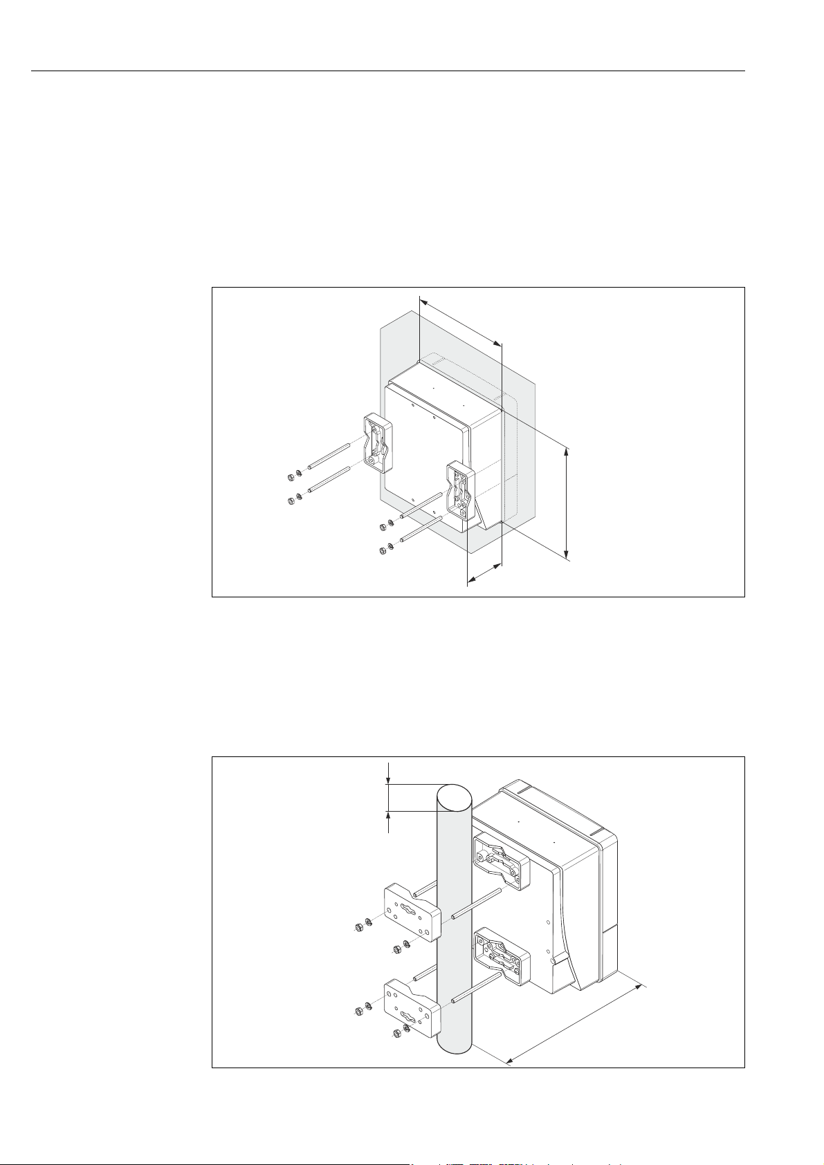
Pipe mounting
The assembly should be performed by following the instructions in the diagram.
Caution!
"
If a warm pipe is used for installation, make sure
that the housing temperature does not exceed the max. permitted value of +60 °C (+140 °F).
A0001131
Fig. 20: Engineering unit mm (in)
26 Endress+Hauser
A0001132

Proline t-mass 65 PROFIBUS DP/PA Installation
4.4 Post-installation check
Perform the following checks after installing the measuring device in the pipe:
Measuring device condition and specifications Notes
Is the measuring device undamaged (visual inspection)? –
Does the device correspond to specifications at the measurement point, including
process temperature and pressure, ambient temperature, measuring range, etc.?
Check the name plate.
Installation Notes
Correct alignment of pipe/gasket/flowmeter body? → 13
Professional installation, e.g. correct pipe internal diameter, correctly sized gaskets? → 13
Is the position chosen for the sensor correct, in other words suitable for sensor type,
fluid properties and fluid temperature?
Is there sufficient upstream and downstream pipe sensor? → 15
Correct installation of flow conditioner (if fitted)? → 16
Does the arrow on the sensor match the direction of flow through the pipe? → 14
Correct sensor depth (insertion sensor only)? → 19
Process environment/process conditions Notes
Is the measuring device protected against moisture and direct sunlight? –
Is the measuring device protected against overheating? → 18
→ 7
→ 14
Is the measuring device protected against excessive vibration? → 18, → 116
Check gas conditions (e. g. purity, dryness, cleanliness) Select suitable orien-
tation → 14
Endress+Hauser 27
Electrical connection Proline t-mass 65 PROFIBUS DP/PA
5 Electrical connection
#
Warning!
When connecting Ex-certified measuring devices, see the notes and diagrams in the Ex-specific supplement to these Operating Instructions. Please do not hesitate to contact your
Endress+Hauser sales center if you have any questions.
5.1 Cable specifications
5.1.1 PROFIBUS DP cable specifications
Cable type
Two versions of the bus line are specified in IEC 61158. Cable type A can be used for all
transmission rates up to 12 Mbit/s. Refer to the table for the cable parameters:
Cable type A
Characteristic impedance 135 to 165 at a measuring frequency of 3 to 20 MHz
Cable capacitance < 30 pF/m
Core cross-section >0.34 mm
Cable type Twisted in pairs, 1 × 2, 2 × 2 or 1 × 4 wire
Loop-resistance 110 /km
Signal damping Max. 9 dB over the entire length of the cable section
Shielding Copper braided shielding or braided shielding and foil shielding
, corresponds to 22 AWG
Bus structure
Note the following points:
• The maximum line length (segment length) depends on the transmission rate.
For cable type A, the maximum line length (segment length) is as follows:
Transmission rate [kBit/s] 9.6 to 93.75 187.5 500 1,500 3,000 to
Line length [m]([inch]) 1,200 (4,000) 1,000
(3,300)
400 (1,300) 200 (650) 100
12,000
• A maximum of 32 users are permitted per segment.
• Each segment is terminated at either end with a terminating resistor.
• The bus length or the number of users can be increased by introducing a repeater.
• The first and last segment can comprise max. 31 devices.
The segments between the repeaters can comprise max. 30 stations.
• The maximum distance between two bus users can be calculated as follows:
(NO_REP + 1) × segment length
Note!
!
NO_REP = maximum number of repeaters that may be switched in series depending on
the repeater in question.
Example
In accordance with manufacturer specifications, 9 repeaters can be switched in series when
using a standard line.
The maximum distance between two bus users at a transmission rate of 1.5 MBit/s can be
calculated as follows: (9 + 1) × 200 m = 2000 m.
28 Endress+Hauser

Proline t-mass 65 PROFIBUS DP/PA Electrical connection
Spurs
Note the following points:
• Length of spurs < 6.6 m (21.7 ft) (at max. 1.5 MBit/s)
• No spurs should be used for transmission rates >1.5 MBit/s. The line between the connector and the bus driver is described as a spur. Experience has shown that you should proceed
with caution when configuring spurs. For this reason, you cannot presume that the sum of
all spurs at 1.5 MBit/s may be 6.6 m (21.7 ft). This is affected greatly by the arrangement
of the field devices. Therefore, we recommend you do not use any spurs, if possible, at
transmission rates >1.5 MBit/s.
• If you cannot avoid using spurs, then they may not include any bus terminators.
Bus termination
It is important to terminate the RS485 line correctly at the start and end of the bus segment
since impedance mismatch results in reflections on the line which can cause faulty data
transfer → 46.
Further information
General information and further notes regarding the wiring can be found in BA00034S/04:
"Guidelines for planning and commissioning, PROFIBUS DP/PA, field communication".
5.1.2 Shielding and grounding
When planning the shielding and grounding for a fieldbus system, there are three important
points to consider:
• Electromagnetic compatibility (EMC)
• Explosion protection
• Safety of the personnel
To ensure the optimum electromagnetic compatibility of systems, it is important that the
system components and above all the cables, which connect the components, are shielded
and that no portion of the system is unshielded. Ideally, the cable shields are connected to
the normally metal housings of the connected field devices. Since these are generally connected to the protective ground, the shield of the bus cable is grounded many times. Ensure
that the stripped and twisted lengths of cable shield to the ground terminal are as short as
possible.
This approach, which provides the best electromagnetic compatibility and personnel safety,
can be used without restriction in systems with good potential matching.
In the case of systems without potential matching, a power supply frequency (50 Hz) equalizing current can flow between two grounding points which, in unfavorable cases, e.g. when
it exceeds the permissible shield current, may destroy the cable.
To suppress the low frequency equalizing currents, it is therefore recommended - in the case
of systems without potential equalization - to connect the cable shield directly to the building ground (or protective ground) at one end only and to use capacitive coupling to connect
all other grounding points.
Caution!
"
The statutory EMC requirements are only met if the cable shield is grounded at both ends!
5.2 Connecting the remote version
!
Endress+Hauser 29
Note!
A cable is not supplied for the remote version.
Electrical connection Proline t-mass 65 PROFIBUS DP/PA
N
i
c
h
t
u
n
t
e
r
S
p
a
n
n
u
n
g
ö
f
f
n
e
n
K
e
e
p
c
o
v
e
r
t
i
g
h
t
w
h
i
l
e
c
i
r
c
u
i
t
s
a
r
e
a
l
i
v
e
N
e
p
a
s
o
u
v
r
i
r
l
’
a
p
p
a
r
e
i
l
s
o
u
s
t
e
n
s
i
o
n
K
e
e
p
c
o
v
e
r
t
i
g
h
t
w
h
i
l
e
c
i
r
c
u
i
t
s
a
r
e
a
l
i
v
e
AB
C
D
41 42 43 44
GND
6…
10V
COMMS
+
-
+
-
GND
COMMS
--
++
41 42 43 44
6…
10V
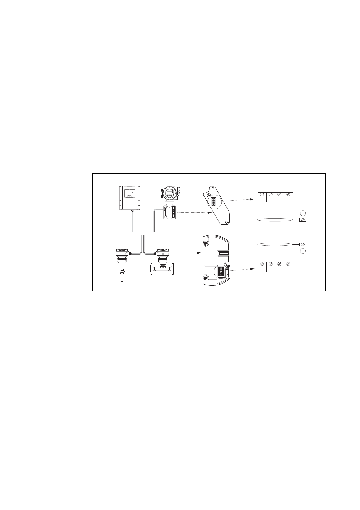
5.2.1 Connecting connecting cable for sensor/transmitter
#
Warning!
• After removing the electronics cover, there is a risk of electric shock as shock protection is
removed! Switch off the measuring device before removing internal covers.
• Risk of electric shock. Connect the protective earth to the ground terminal on the housing
before the power is supplied.
1. Remove the connection compartment cover by loosening the fixing screws on the trans-
mitter and sensor housing.
2. Feed the connecting cable through the appropriate cable entry.
3. Establish the connections between sensor and transmitter in accordance with the wir-
ing diagram (→ 21 or see wiring diagram in screw cap; wire cross-section: max. 2.5
mm² (14 AWG)).
4. Screw the connection compartment cover back onto the sensor and transmitter hous-
ing.
!
A0005123
Fig. 21: Connecting the remote version
A Wallmount housing; Non-hazardous area and zone 2 (ATEX II3G, FM/CSA)
B Field housing; Zone 1 (ATEX II2GD, IECEx, FM/CSA)
C Remote sensor insertion
D Remote sensor flanged
Wire colors (when supplied by Endress+Hauser):
Terminal no. 41 = white; 42 = brown; 43 = green; 44 = yellow
see separate "Ex documentation"
see separate "Ex documentation"
5.2.2 Cable specification, connecting cable
A cable with the following specifications must be used for the remote version:
• 2 × 2 × 0.5 mm² (AWG 20) PVC cable with common shield (2 twisted pairs)
• Conductor resistance: 40 /km ( 131.2 /1000 ft)
•Operating voltage: 250 V
• Temperature range: –40 to +105 °C (–40 to +221 °F)
• Overall nominal diameter: 8.5 mm (0.335")
• Maximum cable length: 100 m (328 feet)
Note!
• The cable must be installed securely to prevent movement
• The cable should be of sufficient diameter to provide adequate sealing of the cable gland
→ 113.
30 Endress+Hauser
 Loading...