

Endress+Hauser Proline t-mass 65F, Proline t-mass 65I Technical Information
Technical Information
Proline t-mass 65F, 65I
Thermal mass flow measuring system
Direct mass flow measurement of gases
Application
For measuring the mass flowrate of a wide range of gas
types e.g.
• Compressed air
• Natural gas flow to boilers / dryers
• Carbon Dioxide flow in breweries
• Biogas and aeration air in waste water plants
• Gas production (e. g. Ar, N
• Leakage detection
Approvals for hazardous area:
• ATEX, FM, CSA
Connection to all common process control systems:
®
•HART
TI069D/24/ae
, Profibus® DP, MODBUS® RS485
, CO2, He, O2)
2
Your benefits
Direct measurement of gas mass flow. Provides temperature as an output.
The Proline transmitter concept comprises:
• Modular device and operating concept resulting in a
higher degree of efficiency
• Quick setup operating menus for ease of commissioning
• On board software freely allows the selection of up to
20 pure gases and creation of mixed gases with a
maximum of 8 components (e. g. Biogas)
The t-mass sensors offer:
• Negligible pressure drop or loss
• Wide turndown of up to 100:1
• Insertion version can be programmed for circular pipe
or rectangular ducting installation
• Each device individually calibrated and delivered with
a traceable certificate
• Can be calibrated with flow conditioner on request.
• Optional cold tap device for insertion allowing ease of
removal/replacement for low pressure and non-toxic
gas applications.

Table of contents
Proline t-mass 65F, 65I
Function and system design. . . . . . . . . . . . . . . . . . . . . 3
Measuring principle . . . . . . . . . . . . . . . . . . . . . . . . . . . . . . . . . . . 3
Measuring system . . . . . . . . . . . . . . . . . . . . . . . . . . . . . . . . . . . . . 3
Input . . . . . . . . . . . . . . . . . . . . . . . . . . . . . . . . . . . . . . 4
Measured variable . . . . . . . . . . . . . . . . . . . . . . . . . . . . . . . . . . . . 4
Measuring range (air at ambient conditions) . . . . . . . . . . . . . . . . . 4
Input signal . . . . . . . . . . . . . . . . . . . . . . . . . . . . . . . . . . . . . . . . . 6
Output . . . . . . . . . . . . . . . . . . . . . . . . . . . . . . . . . . . . . 6
Output signal . . . . . . . . . . . . . . . . . . . . . . . . . . . . . . . . . . . . . . . . 6
Signal on alarm . . . . . . . . . . . . . . . . . . . . . . . . . . . . . . . . . . . . . . 7
Load . . . . . . . . . . . . . . . . . . . . . . . . . . . . . . . . . . . . . . . . . . . . . . 7
Low flow cut off . . . . . . . . . . . . . . . . . . . . . . . . . . . . . . . . . . . . . . 7
Galvanic isolation . . . . . . . . . . . . . . . . . . . . . . . . . . . . . . . . . . . . . 7
Switching output . . . . . . . . . . . . . . . . . . . . . . . . . . . . . . . . . . . . . 7
Power supply. . . . . . . . . . . . . . . . . . . . . . . . . . . . . . . . 8
Electrical connection
measuring unit . . . . . . . . . . . . . . . . . . . . . . . . . . . . . . . . . . . . . . . 8
Terminal assignment . . . . . . . . . . . . . . . . . . . . . . . . . . . . . . . . . . 9
Electrical connection remote version . . . . . . . . . . . . . . . . . . . . . . . 9
Supply voltage . . . . . . . . . . . . . . . . . . . . . . . . . . . . . . . . . . . . . . 10
Cable entries . . . . . . . . . . . . . . . . . . . . . . . . . . . . . . . . . . . . . . . 10
Remote version cable specifications . . . . . . . . . . . . . . . . . . . . . . . 10
Power consumption . . . . . . . . . . . . . . . . . . . . . . . . . . . . . . . . . . 10
Power supply failure . . . . . . . . . . . . . . . . . . . . . . . . . . . . . . . . . . 10
Potential equalisation . . . . . . . . . . . . . . . . . . . . . . . . . . . . . . . . . 10
Mechanical construction . . . . . . . . . . . . . . . . . . . . . . 20
Design / dimensions . . . . . . . . . . . . . . . . . . . . . . . . . . . . . . . . . 20
Weight
(SI units) . . . . . . . . . . . . . . . . . . . . . . . . . . . . . . . . . . . . . . . . . . 32
Materials . . . . . . . . . . . . . . . . . . . . . . . . . . . . . . . . . . . . . . . . . . 32
Process connections . . . . . . . . . . . . . . . . . . . . . . . . . . . . . . . . . . 33
Human interface . . . . . . . . . . . . . . . . . . . . . . . . . . . . 34
Display elements . . . . . . . . . . . . . . . . . . . . . . . . . . . . . . . . . . . . 34
Operating elements . . . . . . . . . . . . . . . . . . . . . . . . . . . . . . . . . . 34
Remote operation . . . . . . . . . . . . . . . . . . . . . . . . . . . . . . . . . . . . 34
Certificates and approvals . . . . . . . . . . . . . . . . . . . . . 34
CE mark . . . . . . . . . . . . . . . . . . . . . . . . . . . . . . . . . . . . . . . . . . 34
C-tick mark . . . . . . . . . . . . . . . . . . . . . . . . . . . . . . . . . . . . . . . . 34
Ex approval . . . . . . . . . . . . . . . . . . . . . . . . . . . . . . . . . . . . . . . . 34
PROFIBUS DP certification . . . . . . . . . . . . . . . . . . . . . . . . . . . . . 34
MODBUS certification . . . . . . . . . . . . . . . . . . . . . . . . . . . . . . . . 34
Other standards and guidelines . . . . . . . . . . . . . . . . . . . . . . . . . . 35
Pressure Equipment Directive . . . . . . . . . . . . . . . . . . . . . . . . . . 35
Accessories . . . . . . . . . . . . . . . . . . . . . . . . . . . . . . . . 36
Device-specific accessories . . . . . . . . . . . . . . . . . . . . . . . . . . . . . 36
Measuring principle-specific accessories . . . . . . . . . . . . . . . . . . . 36
Communication-specific accessories . . . . . . . . . . . . . . . . . . . . . . 36
Service-specific accessories . . . . . . . . . . . . . . . . . . . . . . . . . . . . . 36
Documentation . . . . . . . . . . . . . . . . . . . . . . . . . . . . . 37
Performance characteristics. . . . . . . . . . . . . . . . . . . . 10
Reference calibration conditions . . . . . . . . . . . . . . . . . . . . . . . . . 10
Maximum measured error . . . . . . . . . . . . . . . . . . . . . . . . . . . . . 10
Repeatability . . . . . . . . . . . . . . . . . . . . . . . . . . . . . . . . . . . . . . . . 10
Response time . . . . . . . . . . . . . . . . . . . . . . . . . . . . . . . . . . . . . . 10
Operating conditons: Installation. . . . . . . . . . . . . . . . 11
Installation instructions . . . . . . . . . . . . . . . . . . . . . . . . . . . . . . . . 11
Inlet and outlet runs . . . . . . . . . . . . . . . . . . . . . . . . . . . . . . . . . . 12
Insertion version . . . . . . . . . . . . . . . . . . . . . . . . . . . . . . . . . . . . . 16
Length of connecting cable . . . . . . . . . . . . . . . . . . . . . . . . . . . . . 18
Operating conditions: Environment. . . . . . . . . . . . . . 18
Ambient temperature range . . . . . . . . . . . . . . . . . . . . . . . . . . . . 18
Storage temperature . . . . . . . . . . . . . . . . . . . . . . . . . . . . . . . . . . 18
Degree of protection . . . . . . . . . . . . . . . . . . . . . . . . . . . . . . . . . . 18
Shock resistance . . . . . . . . . . . . . . . . . . . . . . . . . . . . . . . . . . . . . 18
Vibration resistance . . . . . . . . . . . . . . . . . . . . . . . . . . . . . . . . . . 18
Electromagnetic compatibility (EMC) . . . . . . . . . . . . . . . . . . . . . 18
Operating conditions: Process . . . . . . . . . . . . . . . . . . 19
Medium temperature range . . . . . . . . . . . . . . . . . . . . . . . . . . . . 19
Pressure loss . . . . . . . . . . . . . . . . . . . . . . . . . . . . . . . . . . . . . . . . 19
Medium pressure range (nominal pressure) . . . . . . . . . . . . . . . . . 19
Medium pressure . . . . . . . . . . . . . . . . . . . . . . . . . . . . . . . . . . . . 19
Registered trademarks. . . . . . . . . . . . . . . . . . . . . . . . 37
Ordering information. . . . . . . . . . . . . . . . . . . . . . . . . 38
2 Endress+Hauser
Proline t-mass 65F, 65I
Function and system design
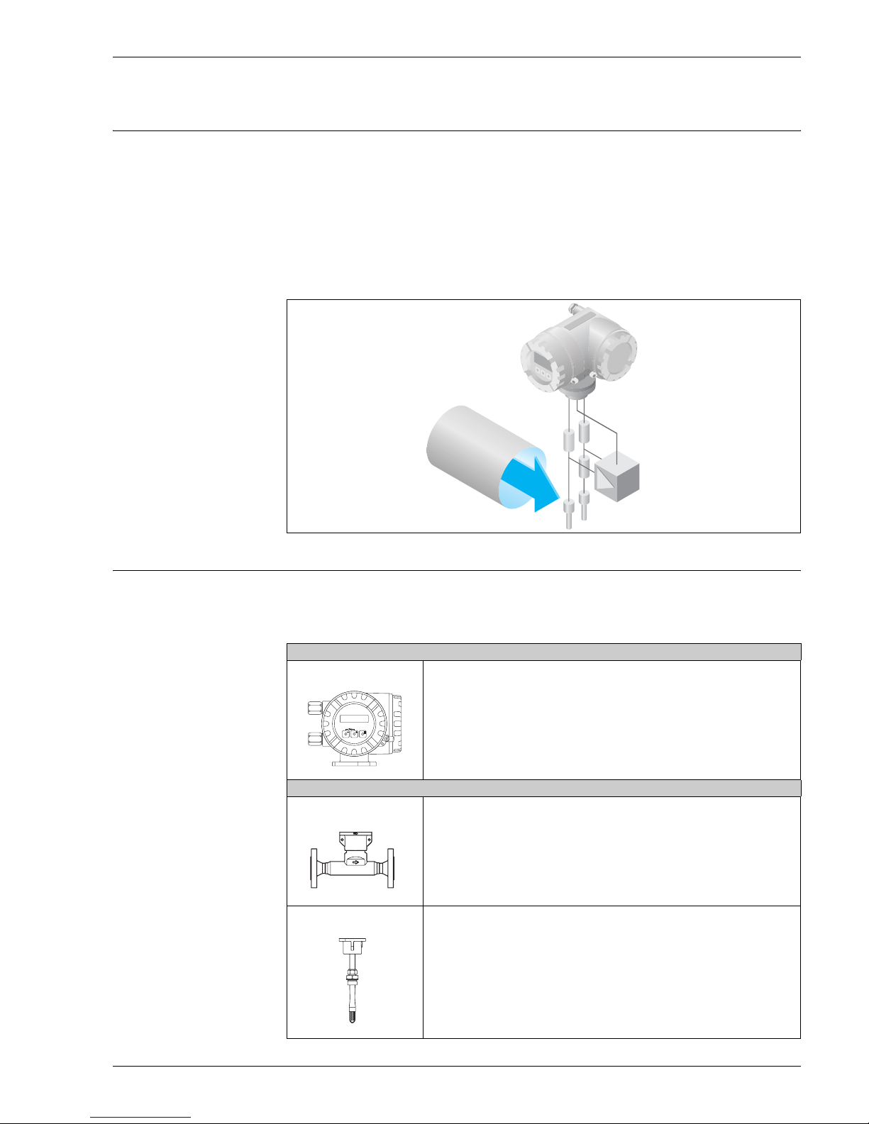
Measuring principle Thermal dispersion principle
The thermal principle operates by monitoring the cooling effect of a gas stream as it passes over a heated transducer (PT100).
Gas flowing through the sensing section passes over two PT 100 RTD transducers one of which is used conventionally as a temperature sensing device, whilst the other is used as a heater. The temperature sensor monitors the actual process values whilst the heater is maintained at a constant differential temperature above this
by varying the power consumed by the sensor. The greater the mass flow, the greater the cooling effect and
power required to maintain the differential temperature. The measured heater power is therefore a measure
of the gas mass flowrate.
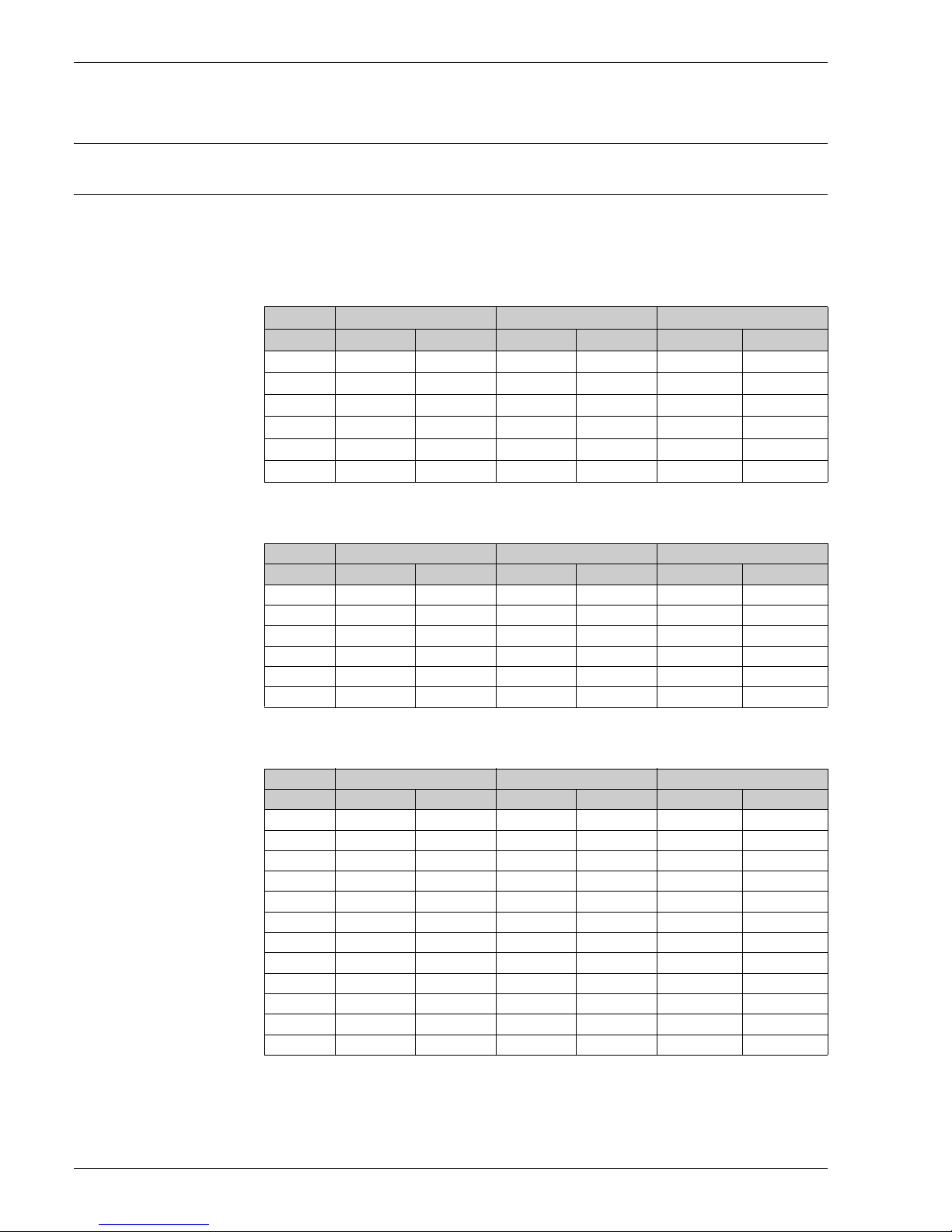
Measuring system The measuring system consists of a transmitter and a sensor. Two versions are available:
• Compact version: transmitter and sensor form a single mechanical unit.
• Remote version: transmitter and sensor are mounted physically separate from one another.
Transmitter
t-mass 65
F
I
Esc
-
+
E
• Two-line liquid-crystal display
• Configuration using push button operation
a0003671
Sensor
• Flanged version
• Nominal diameters DN 15 to 100 (1/2" to 4")
• Sensor body material:
- 1.4404, 316L SS
- CF3M
• Transducer body material:
- 1.4404, 316L SS, Alloy C22
a0005137
• Insertion version
• Sensor length 235/335/435/608 for DN 80 to 1500
(9.25"/13.2"/17.1"/23.9" for line size 3" to 60")
• Sensor body material:
-1.4404, 316/316L SS
• Transducer body material:
- 1.4404/316L SS, Alloy C22
a0005136
Endress+Hauser 3
a0005138
Input
Measured variable Mass flow
Gas temperature
Proline t-mass 65F, 65I
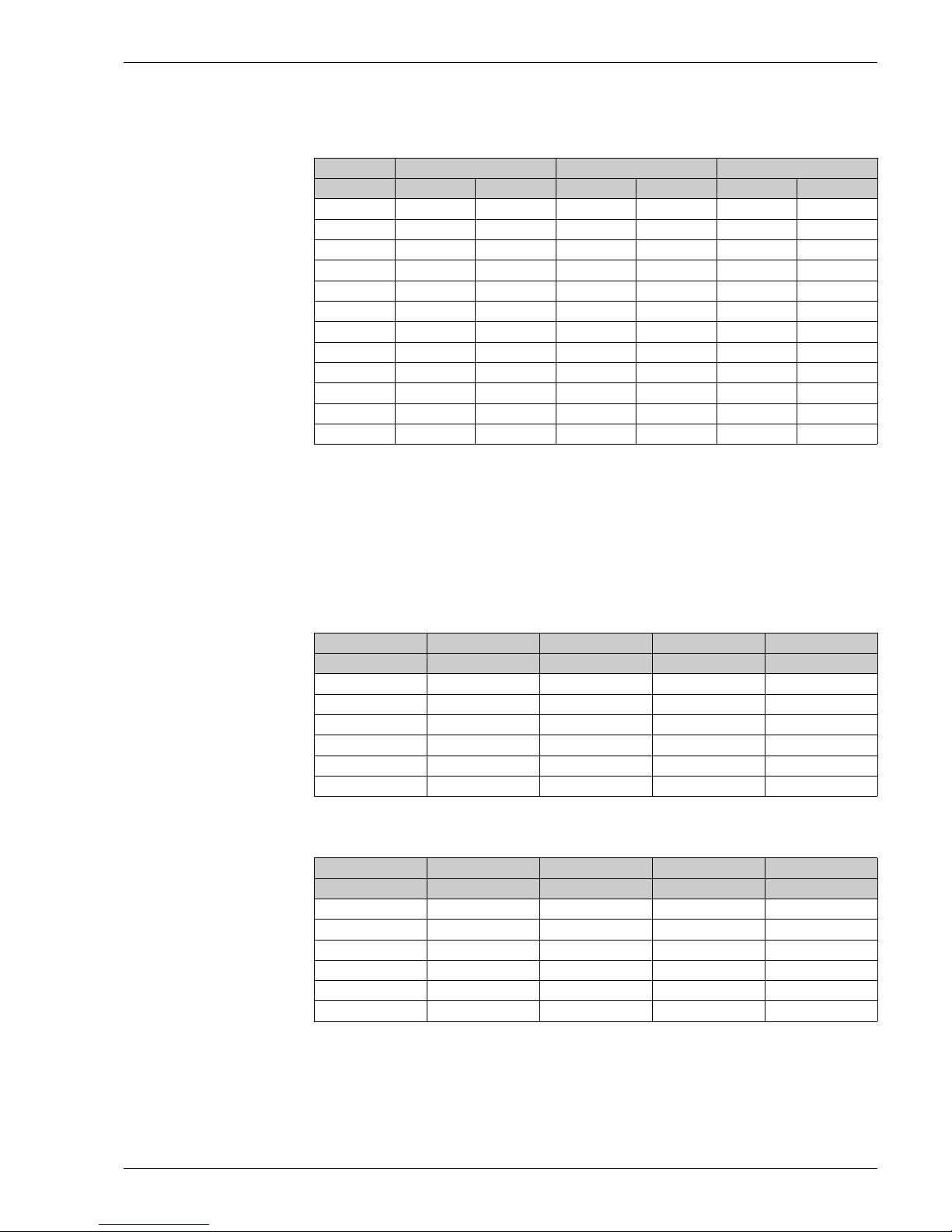
Measuring range
(air at ambient conditions)
The measuring range is dependant on the gas selection, line size and use of flow conditioner. Each meter is
individually calibrated on air and mathematically converted to suit the customer specific gas, where required.
The table below defines the ranges available for air without flowconditioner. Please refer to your
Endress+Hauser representative or to Applicator, the selection tool, for other gases and process conditions.
Measuring range for the flanged version, metric units:
DN kg/h Nm3/h at 0°C, 1.013 bar a scf/min. at 15°C, 1.013 bar a
min. max. min. max. min. max.
15 0.5 53 0.38 41 0.23 25
25 2 200 1.5 155 1.0 96
40 6 555 4.6 429 3.0 266
50 10 910 7.7 704 5.0 436
80 20 2030 15.5 1570 10 974
100 38 3750 29 2900 18 1800
Measuring range for the flanged version, US units:
DN lb/h Sm3/h at 59 °F, 14.7 psi a scf/min. at 59 °F, 14.7 psi a
minimum maximum minimum maximum minimum maximum
1/2" 1.1 116 0.4 42 0.23 25
1" 4.4 440 1.6 160 1.0 96
1 1/2" 13.2 1220 4.8 450 3.0 266
2" 22 2002 8 740 5.0 436
3" 44 4466 16 1656 10 974
4" 84 8250 30 3060 18 1800
Measuring range for the insertion version, metric units:
DN kg/h Nm3/h at 0°C, 1.013 bar a scf/min. at 15°C, 1.013 bar a
min. max. min. max. min. max.
80 20 2030 15.5 1570 9.6 974
100 38 3750 29.0 2900 18 1800
150 50 7500 38 5800 24 3600
200 80 12500 62 9666 38 6000
250 120 20000 93 15468 58 9600
300 180 28000 139 21655 86 13440
400 300 50000 232 38670 144 24000
500 500 80000 386 61870 240 38400
600 700 115000 540 88940 336 55200
700 900 159000 696 122970 432 76300
1000 2000 320000 1546 247846 960 153600
1500 2500 720000 1933 556844 1200 345600
In order to achieve optimum performance it is recommended that under operating conditions the maximum
velocity is limited to a value below 70 m/sec.
4 Endress+Hauser
Proline t-mass 65F, 65I
Measuring range for the insertion version, US units:
DN lb/h Sm3/h at 59°F, 14.7 psi a scf/min. at 59°F, 14.7 psi a
minimum maximum minimum maximum minimum maximum
3" 44 4466 16 1657 9 926
4" 84 8250 30 3060 17 1710
6" 110 16500 40 6120 22.8 3420
8" 176 27500 64 10200 36.5 5700
10" 264 44000 98 16300 55 9120
12" 396 61000 146 22855 82 12768
16" 660 110000 245 40810 136 22800
20" 1100 176000 408 65300 228 36480
24" 1540 253000 570 93870 319 52440
28" 1980 349800 735 129800 410 22504
40" 4400 704000 1630 261200 912 145920
60" 5500 1584000 2040 587750 1140 328320
In order to achieve optimum performance it is recommended that under operating conditions the maximum
velocity is limited to a value below 230 ft/sec.
Caution!
The flowrates shown are representative of the calibrated conditions only and do not necessarily reflect what
the meter can measure under operating conditions and actual internal pipe dimensions found on site. To
correctly size and select a meter, it is recommended that you either contact your local Endress+Hauser
representative or refer to the Endress+Hauser software package Applicator.
Examples in metric units:
Line Size Gas Process pressure Temperature Max. Flowrate
DN bar a °C kg/h
50 Air 1 25 910
50 Air 3 25 3300
50 CO
50 CO
50 Methane 1 25 795
50 Methane 3 25 1500
2
2
1251300
3253950
Examples in US units:
Line Size Gas Process pressure Temperature Max. Flowrate
Dia psia °F lb/hr
2" Air 14.7 77 2002
2" Air 44.1 77 7260
2" CO
2" CO
2" Methane 14.7 77 1749
2" Methane 44.1 77 3300
2
2
14.7 77 2860
44.1 77 8690
Endress+Hauser 5

Input signal Status input (auxiliary input) for HART version:
U = 3 to 30 V DC, R
= 5 kΩ, galvanically isolated; switch level: ±3 to ±30 V DC
i
Configurable for: totalizer reset, positive zero return, zero point adjustment
Status input (auxiliary input) for MODBUS RS485 version:
U = 3 to 30 V DC, R
= 3 kΩ, galvanically isolated; switch level: ±3 to ±30 V DC, independent of polarity
i
Configurable for: totalizer reset, positive zero return, zero point adjustment
Current input:
Active/passive selectable, galvanically isolated, resolution: 2 μA
• Active: 4 to 20 mA, Ri ≤ 150 Ω, U
• Passive: 0/4 to 20 mA, R
≤ 150 Ω, U
i
= 24 V DC, short-circuit proof
out
= 30 V DC
max
Output
Output signal Current output:
Active/passive selectable, galvanically isolated, time constant selectable (0.0 to 100.0 s), full scale value
selectable, temperature coefficient: typically 0.005% o.r./°C, resolution: 0.5 μA
• Active: 0/4 to 20 mA, R
• Passive: 4 to 20 mA; supply voltage V
Note!
If the current output is used as a temperature output, please observe the following information:
Class B according to EN 6075
< 700 Ω (at HART: RL ≥ 250 Ω)
L
18 to 30 V DC; Ri ≥ 700 Ω
S
Proline t-mass 65F, 65I
Pulse/frequency output:
Active: 24 V DC , 25 mA (max. 250 mA during 20 msec), R
> 100 Ω
L
Passive: open collector, 30 V DC, 250 mA, galvanically isolated.
• Frequency output: full scale frequency 2 to 1000 Hz (f
= 1250 Hz), on/off ratio 1:1, pulse width max. 2s,
max
time constant selectable (0.0 to 100.0 s)
• Pulse output: pulse value and pulse polarity can be selected, pulse width adjustable (0.5 to 2000 ms).
PROFIBUS DP interface:
• PROFIBUS DP in accordance with IEC 61158, galvanically isolated
• Profile version 3.0
• Data transmission rate: 9.6 kBaud to 12 MBaud
• Automatic data transmission rate recognition
• Signal encoding: NRZ-Code
• Function blocks: 3 x Analog Input, 2 x Totalizer
• Output data: Mass flow, Corrected volume flow, Temperature, Totalizer 1 to 2
• Input data: Positive zero return (ON/OFF), Zero point adjustment, Totalizer control and Pressure display
value
• Bus address can be set at the measuring device via miniature switches or using local display (optional)
MODBUS RS485 interface:
• MODBUS device type: slave
• Address range: 1 to 247
• Bus address can be set at the measuring device via miniature switches or the on-site display (optional)
• Supported function codes: 03, 04, 06, 08, 16, 23
• Broadcast: supported with the function codes 06, 16, 23
• Physical interface: RS485 in accordance with EIA/TIA-485 standard
• Supported baudrate: 1200, 2400, 4800, 9600, 19200, 38400, 57600, 115200 Baud
• Transmission mode: RTU or ASCII
•Response times:
Direct data access = typically 25 to 50 ms
Auto-scan buffer (data block) = typically 3 to 5 ms
6 Endress+Hauser

Proline t-mass 65F, 65I
Signal on alarm Current output:
Failsafe mode selectable (e.g. in accordance with NAMUR Recommendation NE 43)
Current input:
Failsafe value selectable
Pulse/frequency output:
Failsafe mode selectable
Status output:
“Non conductive” in the event of fault or power supply failure.
Relay output:
“De-energized” in the event of fault or power supply failure.
PROFIBUS DP:
Status and alarm messages in accordance with PROFIBUS Profile Version 3.0.
MODBUS RS485:
If an error occurs, the value NaN (not a number) is output for the measured values.
Load see “Output signal”
Low flow cut off Switch points for low flow cut off are programmable
Galvanic isolation All circuits for inputs, outputs, and power supply are galvanically isolated from each other.
Switching output Relay output:
Normally closed (NC) or normally open (NO) contacts available
(factory setting: relay 1 = NO, relay 2 = NC), max. 30 V / 0.5 A AC; 60 V / 0.1 A DC, galvanically isolated.
Configurable for: error messages, limit values
Endress+Hauser 7
Power supply
Esc
E
-
+
Esc
E
-
+
Proline t-mass 65F, 65I
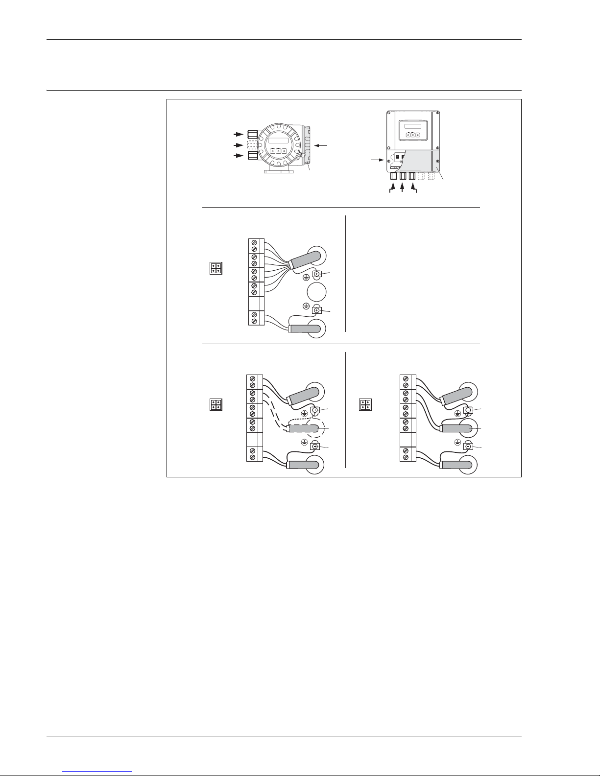
Electrical connection
measuring unit
XY
d
g
b
a
a
b
d/(g)
(d)
HART
–27
+26
–25
f
+24
+22
+20
N (L-) 2
L1 (L+)1
–23
–21
d
e
c
b
PROFIBUS DP
N (L-)
L1 (L+)
27
26
–
25
+
24
–
23
+
22
–
21
+
20
2
1
d
e
g
c
b
B (RS485)
A (RS485)
f f
B (RS485)
A (RS485)
PROFIBUS PA*
FOUNDA
MODBUS RS485
27
26
25
–
24
+
23
–
22
+
21
–
20
+
N (L-)
2
L1 (L+)
1
TION Fieldbus*
Connecting the transmitter, cable cross-section: max. 2.5 mm2 (AWG 13)
A View X (field housing)
B View Y (wall-mount housing)
*) Not available yet (left in deliberately)
a Cover of the connection compartment
b Cable for power supply: 85 to 260 V AC, 20 to 55 V AC,16 to 62 V DC
Terminal No. 1: L1 for AC, L+ for DC
Terminal No. 2: N for AC, L– for DC
c Ground terminal for protective conductor
d Signal cable: See Terminal assignment → Page 7
Fieldbus cable:
Terminal Nr. 26: PROFIBUS DP / MODBUS RS485 → A (RxD/TxD-P)
Terminal Nr. 27: PROFIBUS DP / MODBUS RS485 → B (RxD/TxD-N)
e Ground terminal for signal-cable shield / RS485 line
Observe that the stripped and twisted lengths of cable shield to the ground terminal are as short as possible
(max. 5 mm)
f Service connector for connecting service interface FXA193 (Fieldcheck, Tof Tool - Fieldtool)
g Signal cable: See Terminal assignment → Page 7
PROFIBUS cable for external termination, opt ional:
Terminal No. 24: +5 V
Terminal No. 25: DGND
MODBUS RS485 cable for status input:
Terminal No. 24: 3 to 30 V DC, R
Terminal No. 25: GND
= 3 kΩ
ι
d
e
g
c
b
a0005135
8 Endress+Hauser
Proline t-mass 65F, 65I
6
Terminal assignment
Terminal No. (inputs/outputs)
Order variant 20 (+) / 21 (–) 22 (+) / 23 (–) 24 (+) / 25 (–) 26 (+) / 27 (–)
Fixed communication boards (permanent assignment)
65***-*********A - - Frequency output
65***-*********B Relay output Relay output Frequency output
65***-*********J - - +5V (ext. termination) PROFIBUS DP
65***-*********Q - - Status input MODBUS RS485
65***-*********R - - Current output 2
65***-*********S - -
65***-*********T - -
65***-*********U - - Current output 2
Flexible communication boards
65***-*********5 Status input Current input Frequency output Current output
65***-*********6 Status input Current input Current output 2 Current output
65***-*********8 Status input Frequency output Current output 2 Current output
Ex i, active
Frequency output
Ex i, passive
Frequency output
Ex i, passive
Ex i, passive
Current output
HART
Current output
HART
Current output 1
Ex i active, HART
Current output Ex i
Active, HART
Current output Ex i
Passive, HART
Current output 1
Ex i passive, HART
HART
HART
HART
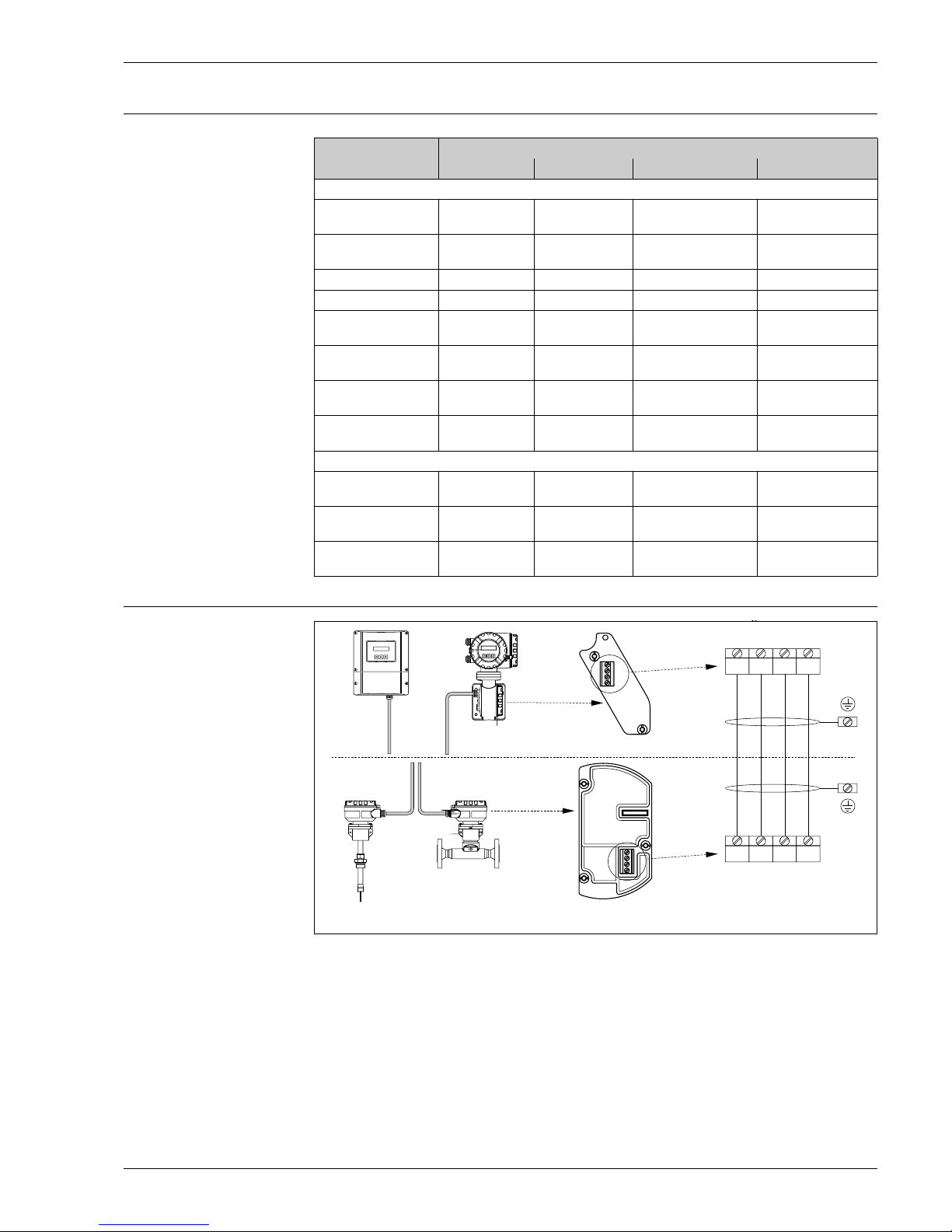
Electrical connection remote
version
C D
A Wallmount housing; Non-hazardous area and zone 2 (ATEX II3G)
B Wallmount housing; Zone 1 (ATEX II2G)
C Remote sensor insertion version
D Remote sensor flange d version
Wire colors (when supplied by Endress+Hauser):
Terminal no. 41 = white; 42 = brown; 43 = green; 44 = yellow
(Color code according to DIN 47100)
…
10V
GND
GND
COMMS
-
41 42 43 44
41 42 43 44
--
-
+
++
COMMS
6…
10V
+
a0005123
Warning!
Do not provide separate power to remote sensor. The power must be provided by the transmitter.
Endress+Hauser 9

Supply voltage 85 to 260 V AC, 45 to 65 Hz
20 to 55 V AC, 45 to 65 Hz
16 to 62 V DC
Cable entries Power-supply and signal cables (inputs/outputs):
• Cable entry M20 x 1.5, 8 to 12 mm (0.3 to 0.47")
• Thread for cable entries, G 1/2", 1/2" NPT
Connecting cable for remote version:
• Cable entry M20 x 1.5, 8 to 12 mm (0.3 to 0.47")
• Thread for cable entries, G 1/2", 1/2" NPT
Proline t-mass 65F, 65I
Remote version
cable specifications
Power consumption AC: 85 to 260 V = 18.2 W ; 20 to 55 V = 14 W ; (including sensor)
Power supply failure Lasting minimum 1 power cycle
Potential equalisation No measures necessary
• 2 x 2 x 0.5 mm² (AWG 20) PVC cable with common shield (2 twisted pairs)
• Conductor resistance: ≤ 40 Ω/km [≤ 131.2 Ω /1000 ft]
• Capacitance, core/shield: ≤ 0.001 μF/m [≤ 3.280 nF/ft]
• Inductance: ≤ 0.9 μH/m [ ≤ 2.952 μH/ft]
•Operating voltage: ≥ 250 V
• Temperature range: –40 to +105°C [–40 to +221°F]
• Overall nominal diameter: 8.5 mm [0.335"]
• Maximum cable length: 100 m [328 feet]
Operation in zones of severe electrical interference:
The measuring device complies with the general safety requirements in accordance with EN 61010, the EMC
requirements of IEC/EN 61326, and NAMUR recommendation NE 21/43.
Note!
For cable specifications for hazardous area devices please see the additional Ex documentation.
DC: 8 W (including sensor)
• EEPROM/HistoROM T-DAT saves measuring system data if the power supply fails
• HistoROM S-DAT is on exchangeable data storage chip with sensor specific data (pipe type, nominal diam-
eter, serial number, flow conditioner, zero point, etc.)
• Totalizer stops at the last value determined
For devices in hazardous areas please refer to the additional Ex documentation
Performance characteristics
Reference calibration
conditions
Maximum measured error Flanged version:
Repeatability 0.5 % for velocities above 0.2 m/s (0.65 ft/s)
Response time Typically less than 2 seconds for 63 % of a given step change (in either direction).
10 Endress+Hauser
• Accredited according to ISO/IEC 17025
• Tracable to National Standards
• Temperature controlled to within ±0.5°C (± 0.9°F) at atmospheric pressure and humidity controlled
±1.5 % of reading for 100 % to 20 % of full scale at reference conditions
±0.3 % of full scale for 20 % to 1 % of full scale at reference conditions
Insertion version:
±1.5 % of reading plus ±0.5 % of full scale
Note!
• Calibration gas is normally air at reference calibration conditions and with a fully developed flow profile.
• On site performance is dependant on the standard of installation.
Proline t-mass 65F, 65I
Operating conditons: Installation
Thermal meters require a fully developed flow profile as a prerequisite for correct flow measurement. For this
reason, please note the following points when installing the device.
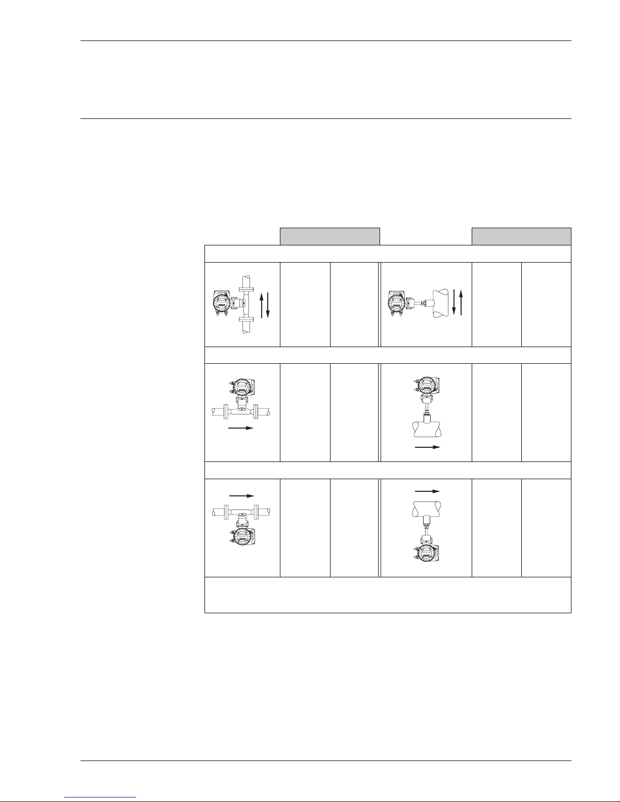
Installation instructions Orientation
The device can generally be installed in any position in the piping. In the case of wet/dirty gases, upward flow
is prefered in vertical pipes to minimise condensation/contamination on or around the sensing element. In
particular, where free condensation can occur (e.g. Biogas) the sensor should be orientated to prevent water
collecting on or around the sensing elements (e.g. do not install the sensor at a low point in the installation
without adequate drainage).
Make sure that the direction arrow on the sensor matches the direction of flow (direction of fluid flow through
the pipe).
Vertical orientation
Flanged version Insertion version
compact
remote
compact
remote
YY
a0005107
Horizontal orientation:
compact
YY
a0005108
Horizontal orientation:
compact
X
a0005109
YY = Recommended orientation
Y = Orientation recommended in certain situations; not recommended in high vibration or unstable installations
X = Not recommended
YY
remote
YY
remote
X
a0005110
a0005111
a0005112
Y
(see note
below)
compact
YY
compact
X
YY
remote
YY
remote
X
Caution!
When mounting an insertion meter in a vertical line it is recommended that a remote version is used or support
is provided for the compact version.
Endress+Hauser 11
Proline t-mass 65F, 65I
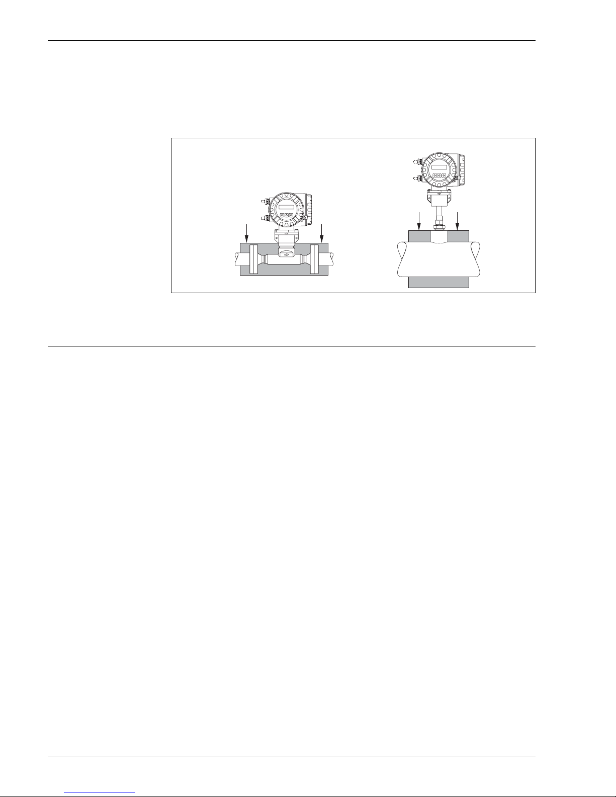
Thermal insulation
When the gas is very humid or saturated with water (eg. Biogas) the pipeline and flowmeter body should be
insulated to prevent water droplets condensing on the pipe wall and/or flow transducer. In extreme cases of
moisture and temperature variation, it may be advisable to provide trace heating of the pipework and/or sensor
body.
a
a = Maximum insulation height for the flanged version
b = Maximum insulation height for the insertion version
a
b
b
a0005122
Inlet and outlet runs The sensitivity of the thermal dispersion principle to low flow rates means the flowmeter can also be sensitive
to internal disturbances in the flowing gas stream (e.g. swirl) especially in the larger pipe diameters (
≥ 6")).
(
≥ DN 150
As a general rule, the installed thermal flow sensor should always be installed as far away as possible from any
flow disturbances. See ISO14511 for further information.
Process components or pipework configuration
When disturbances (e. g. pipe elbows, reducers, valves, T-pieces etc.) are located upstream of the thermal
meter, precautions must be taken to minimise any effects on the measuring performance.
The figure on the following page illustrates the minimum recommended inlet and outlet runs expressed in multiples of the pipe diameter, longer lengths should always be used if they are available in the metering run.
Regardless of any other consideration, the minimum recommendations for inlet and outlet runs on either side
of the sensor are:
Inlet runs:
Minimum 15 x Dia for the flanged version (65F)
Minimum 20 x Dia for the insertion version (65I)
Outlet runs:
Minimum 2 x Dia for the flanged version (65F)
Minimum 5 x Dia for the insertion version (65I)
Note!
• These are minimum values, increasing these dimensions will often improve the flowmeter perfomance.
• Where two or more disturbances are located upstream of the meter, the longest recommended upstream
pipe run is to be observed as an absolute minimum.
• It is always recomended to install control valves downstream of the flowmeter.
• For very light gases such as Helium and Hydrogen all upstream distances should be doubled.
12 Endress+Hauser
 Loading...