

Page 1
TI01333D/06/EN/03.19
71439415
2019-07-01
Products Solutions Services
Technical Information
Proline Prowirl F 200
Vortex flowmeter
Versatile flowmeter with wet steam detection and first-rate accuracy
Application
• Preferred measuring principle for wet/saturated/
superheated steam, gases & liquids (also cryogenic)
• Suitable for a wide range of applications; optimized for
steam applications
Device properties
• Wet steam capabilities for DN 25 to 300 (1 bis 12")
• Flexible positioning of pressure cell
• Industrial siphon design for pressure measurement
• Display module with data transfer function
• Robust dual-compartment housing
• Plant safety: worldwide approvals (SIL, Haz. area)
Your benefits
• Easy energy management – integrated temperature and
pressure measurement for steam and gases
• Space-saving engineering – inlet run compensation
• Same accuracy down to Re 10 000 –
most linear Vortex meter body
• Long-term stability – robust drift-free capacitive sensor
• Convenient device wiring – separate connection
compartment
• Safe operation – no need to open the device due to display
with touch control, background lighting
• Integrated verification – Heartbeat Technology
Page 2

Table of contents
Proline Prowirl F 200
About this document ........................ 3
Symbols .................................... 3
Function and system design ................... 4
Measuring principle ............................ 4
Measuring system ............................. 8
Input ..................................... 9
Measured variable ............................. 9
Measuring range ............................. 10
Operable flow range ........................... 14
Input signal ................................ 15
Output .................................. 16
Output signal ............................... 16
Signal on alarm .............................. 17
Load ..................................... 18
Ex connection data ........................... 19
Low flow cut off ............................. 24
Galvanic isolation ............................ 24
Protocol-specific data .......................... 24
Power supply ............................. 26
Terminal assignment .......................... 26
Pin assignment, device plug ...................... 28
Supply voltage .............................. 29
Power consumption ........................... 30
Current consumption .......................... 30
Power supply failure .......................... 30
Electrical connection .......................... 30
Potential equalization ......................... 35
Terminals ................................. 35
Cable entries ............................... 35
Cable specification ............................ 35
Overvoltage protection ......................... 37
Electromagnetic compatibility (EMC) ............... 50
Process .................................. 50
Medium temperature range ...................... 50
Pressure-temperature ratings .................... 51
Nominal pressure of sensor ...................... 54
Pressure specifications ......................... 54
Pressure loss ............................... 54
Thermal insulation ........................... 54
Mechanical construction .................... 55
Dimensions in SI units ......................... 55
Dimensions in US units ......................... 68
Weight ................................... 75
Materials .................................. 79
Flange connections ........................... 83
Operability ............................... 83
Operating concept ............................ 83
Languages ................................. 83
Local operation .............................. 84
Remote operation ............................ 85
Service interface ............................. 87
Certificates and approvals ................... 87
CE mark ................................... 87
RCM-tick symbol ............................. 87
Ex approval ................................ 87
Functional safety ............................. 89
HART certification ............................ 90
FOUNDATION Fieldbus certification ................ 90
Certification PROFIBUS ......................... 90
Pressure Equipment Directive .................... 90
Experience ................................. 90
Other standards and guidelines ................... 90
Performance characteristics .................. 38
Reference operating conditions ................... 38
Maximum measured error ....................... 38
Repeatability ............................... 41
Response time .............................. 42
Influence of ambient temperature ................. 42
Installation ............................... 42
Mounting location ............................ 42
Orientation ................................ 42
Inlet and outlet runs .......................... 44
Length of connecting cable ...................... 46
Mounting the transmitter housing ................. 47
Special mounting instructions .................... 47
Environment .............................. 48
Ambient temperature range ..................... 48
Storage temperature .......................... 49
Climate class ............................... 49
Degree of protection .......................... 49
Vibration- and shock-resistance ................... 49
Ordering information ....................... 91
Product generation index ....................... 91
Application packages ....................... 91
Diagnostics functions .......................... 91
Heartbeat Technology ......................... 92
Wet steam detection .......................... 92
Wet steam measurement ....................... 92
Accessories ............................... 92
Device-specific accessories ...................... 93
Communication-specific accessories ................ 94
Service-specific accessories ...................... 95
System components ........................... 95
Supplementary documentation ............... 95
Standard documentation ........................ 96
Supplementary device-dependent documentation ....... 96
Registered trademarks ...................... 97
2 Endress+Hauser
Page 3
Proline Prowirl F 200
A
1.
About this document
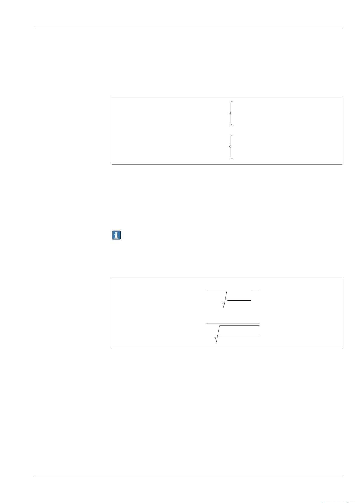
Symbols Electrical symbols
Symbol Meaning
Direct current
Alternating current
Direct current and alternating current
Ground connection
A grounded terminal which, as far as the operator is concerned, is grounded via a
grounding system.
Protective Earth (PE)
A terminal which must be connected to ground prior to establishing any other
connections.
The ground terminals are situated inside and outside the device:
• Inner ground terminal: Connects the protectiv earth to the mains supply.
• Outer ground terminal: Connects the device to the plant grounding system.
Communication symbols
Symbol Meaning
Wireless Local Area Network (WLAN)
Communication via a wireless, local network.
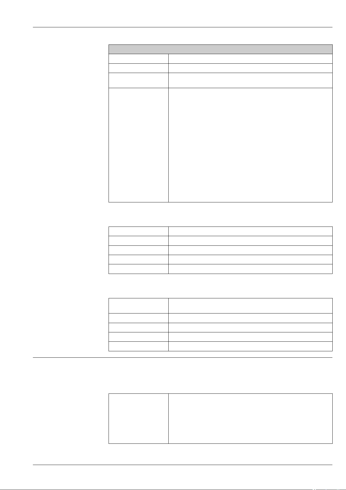
Symbols for certain types of information
Symbol Meaning
Permitted
Procedures, processes or actions that are permitted.
Preferred
Procedures, processes or actions that are preferred.
Forbidden
Procedures, processes or actions that are forbidden.
Tip
Indicates additional information.
Reference to documentation.
Reference to page.
Reference to graphic.
Visual inspection.
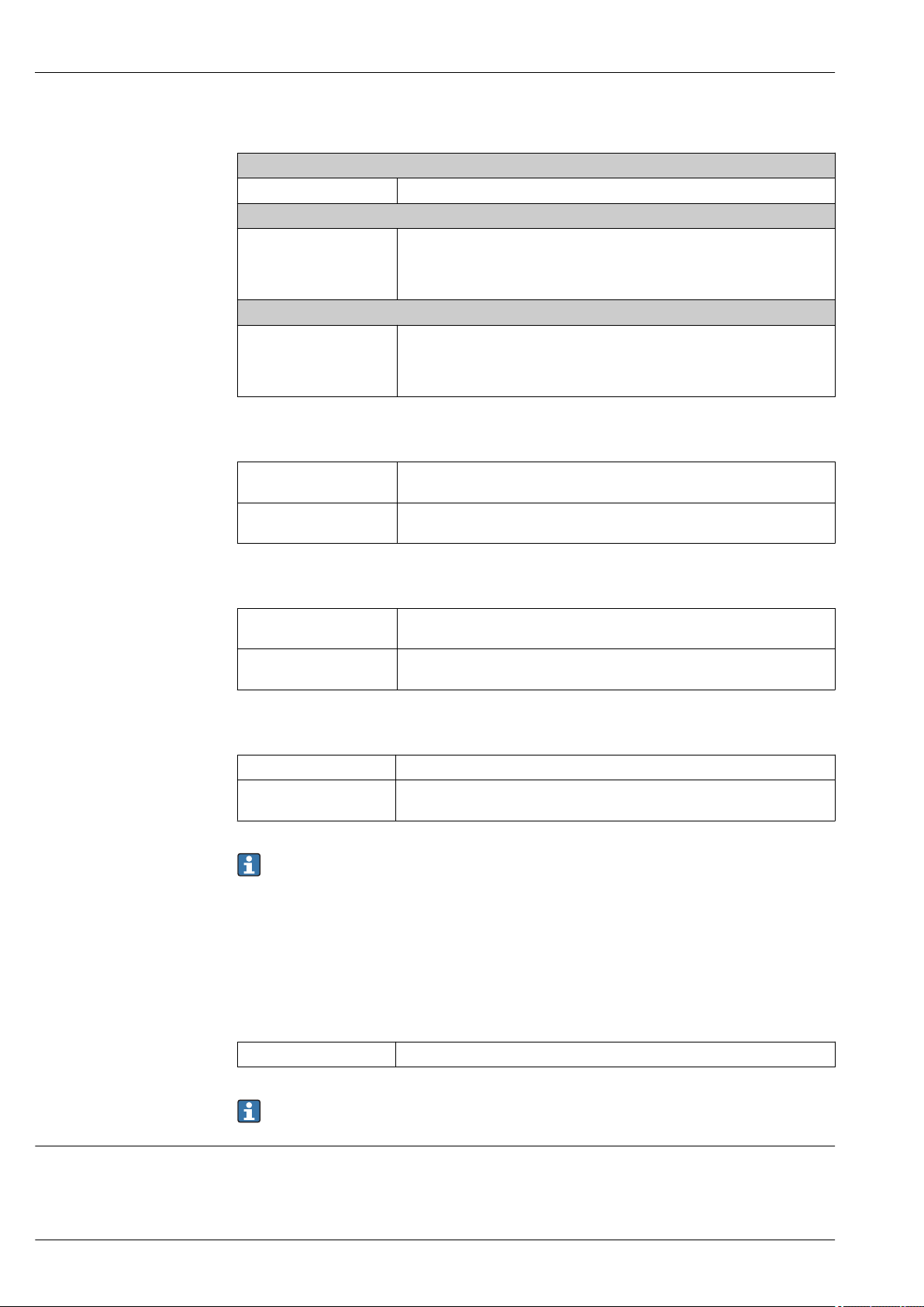
Symbols in graphics
Symbol Meaning
1, 2, 3, ... Item numbers
, 2., 3., … Series of steps
A, B, C, ... Views
A-A, B-B, C-C, ... Sections
Endress+Hauser 3
Page 4
Symbol Meaning
-
.
K-Factor =
Pulses
Unit Volume [m³]
Hazardous area
Safe area (non-hazardous area)
Flow direction
Function and system design
Proline Prowirl F 200
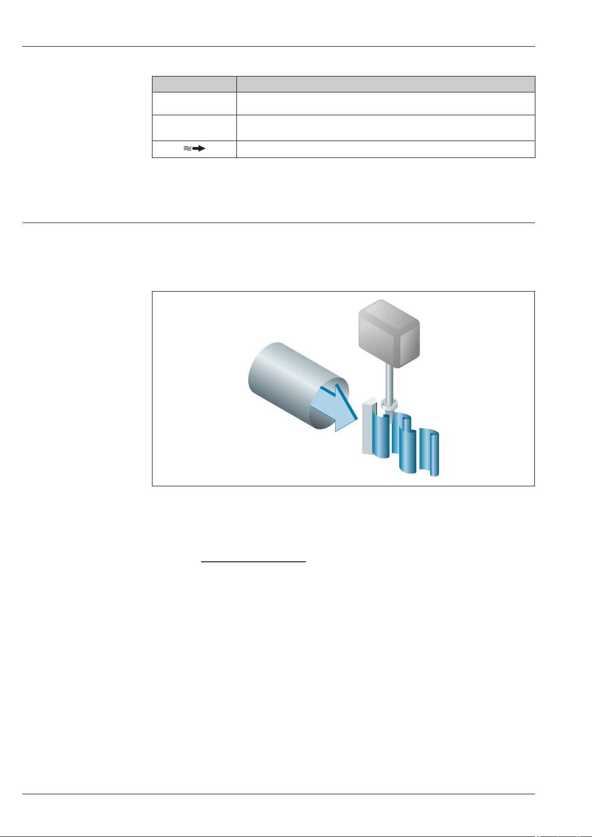
Measuring principle
Vortex meters work on the principle of the Karman vortex street. When fluid flows past a bluff body,
vortices are alternately formed on both sides with opposite directions of rotation. These vortices each
generate a local low pressure. The pressure fluctuations are recorded by the sensor and converted to
electrical pulses. The vortices develop very regularly within the permitted application limits of the
device. Therefore, the frequency of vortex shedding is proportional to the volume flow.
A0033465
1 Sample graphic
The calibration factor (K-factor) is used as the proportional constant:
Within the application limits of the device, the K-factor only depends on the geometry of the device.
It is for Re > 10 000:
• Independent of the flow velocity and the fluid properties viscosity and density
• Independent of the type of substance under measurement: steam, gas or liquid
The primary measuring signal is linear to the flow. After production, the K-factor is determined in
the factory by means of calibration. It is not subject to long-time drift or zero-point drift.
The device does not contain any moving parts and does not require any maintenance.
The capacitance sensor
The sensor of a vortex flowmeter has a major influence on the performance, robustness and
reliability of the entire measuring system.
4 Endress+Hauser
A0003939-EN
Page 5
Proline Prowirl F 200
1 2
The robust DSC sensor is:
• burst-tested
• tested against vibrations
• tested against thermal shock (thermal shocks of 150 K/s)
The measuring device uses the tried-and-tested, capacitance measuring technology from
Endress+Hauser, which is already in use in over 450 000 measuring points worldwide. Thanks to its
design, the capacitance sensor is also particularly mechanically resistant to temperature shocks and
pressure shocks in steam pipelines.
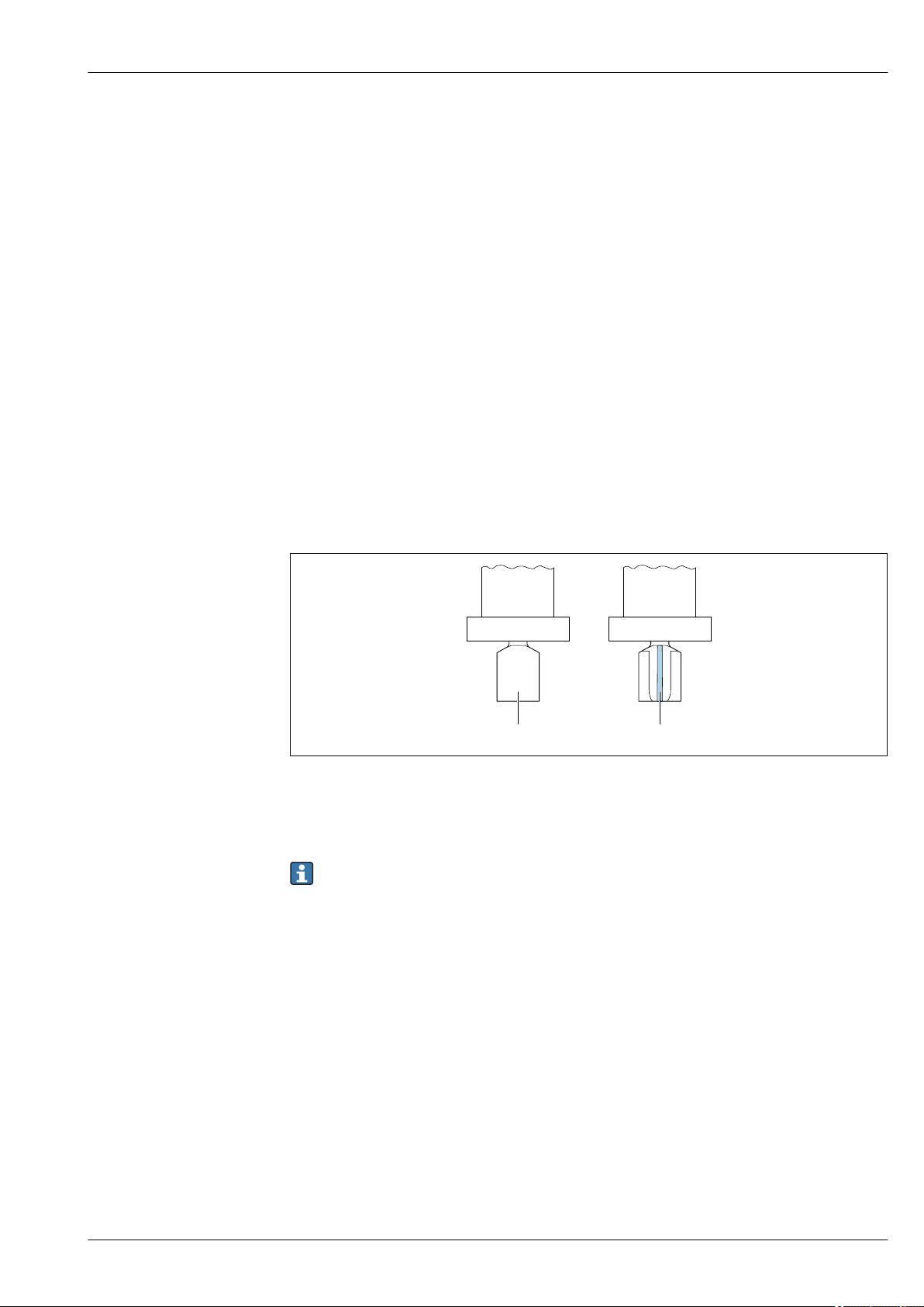
Temperature measurement
The "mass" option is available under the order code for "Sensor version". With this option the
measuring device can also measure the temperature of the medium.
The temperature is measured via Pt 1000 temperature sensors. These are located in the paddle of
the DSC sensor and are therefore in the direct vicinity of the fluid.
Order code for "Sensor version; DSC sensor; measuring tube":
• Option AA "volume; 316L; 316L"
• Option AB "volume; Alloy C22; 316L"
• Option AC "volume; Alloy C22; Alloy C22"
• Option BA "volume high-temperature; 316L; 316L"
• Option BB "volume high-temperature; Alloy C22; 316L"
• Option CA "Mass; 316L; 316L (integrated temperature measurement)"
• Option CB "Mass; Alloy C22; 316L (integrated temperature measurement)"
• Option CC "Mass; Alloy C22; Alloy C22 (integrated temperature measurement)"
A0034068
1 Order code for "Sensor version", option "volume" or "volume high-temperature"
2 Order code for "Sensor version", option "mass"
Pressure and temperature measurement
The "mass" sensor version (integrated pressure/temperature measurement) is available only for
measuring devices in the HART communication mode.
The "mass steam" or "mass gas/liquid" options are available under the order code for "Sensor version;
DSC sensor; measuring tube". With these options, the measuring device can also measure the
pressure and temperature of the fluid.
The temperature is measured via Pt 1000 temperature sensors. These are located in the paddle of
the DSC sensor and are therefore in the direct vicinity of the fluid. Pressure measurement is located
directly on the meter body at the level of the bluff body. The position of the pressure tapping was
chosen so that pressure and temperature could be measured at the same point. This enables accurate
density and/or energy compensation of the fluid using pressure and temperature. The measured
pressure tends to be somewhat lower than the line pressure. For this reason, Endress+Hauser offers
a correction to the line pressure (integrated in the device).
Order code for "Sensor version; DSC sensor; measuring tube":
• Option DA "Mass steam; 316L; 316L (integrated pressure/temperature measurement)"
• Option DB "Mass gas/liquid; 316L; 316L (integrated pressure/temperature measurement)"
Lifelong calibration
Experience has shown that recalibrated measuring devices demonstrate a very high degree of
stability compared to their original calibration: The recalibration values were all within the original
Endress+Hauser 5
Page 6

Proline Prowirl F 200
measuring accuracy specifications of the devices. This applies to the measured volume flow, the
device's primary measured variable.
Various tests and simulation have shown that once the radii of the edges on the bluff body are less
than 1 mm (0.04 in), the resulting effect does not have a negative impact on accuracy.
If the radii of the edges on the bluff body do not exceed 1 mm (0.04 in), the following general
statements apply (in the case of non-abrasive and non-corrosive media, such as in most water and
steam applications):
• The measuring device does not display an offset in the calibration and the accuracy is still
guaranteed.
• All the edges on the bluff body have a radius that is typically smaller in size. As the measuring
devices are naturally also calibrated with these radii, the measuring device remains within the
specified accuracy rating provided that the additional radius that is produced as a result of wear
and tear does not exceed 1 mm (0.04 in).
Consequently, it can be said that the product line offers lifelong calibration if the measuring device is
used in non-abrasive and non-corrosive media.
Inlet run correction
Inlet run correction makes it possible to shorten the necessary inlet run before the measuring device
to a minimum length of 10 × DN. If the inlet run available is too short, the measuring device can
correct the measured error depending on the preceding disruption in the flow profile. This results in
an additional measured error of ±0.5 %o.r.
The Inlet Run Correction function can be used for the following pressure ratings and nominal
diameters:
DN 15 to 150 (1 to 6")
• EN (DIN)
• ASME B16.5, Sch. 40/80
Inlet run correction is possible for the following flow obstructions:
• Single elbow (90° elbow)
• Double elbow (2 × 90° elbows, opposite)
• Double elbow 3D (2 × 90° elbows, opposite, not on one plane)
• Reduction by one nominal diameter size
Inlet and outlet runs to be considered → 44
1)
For detailed information about inlet run correction, see the Special Documentation for the
device
Air and industrial gases
The measuring device enables users to calculate the density and energy of air and industrial gases.
The calculations are based on time-tested standard calculation methods. It is possible to
automatically compensate for the effect of pressure and temperature via an external or constant
value.
This makes it possible to output the energy flow, standard volume flow and mass flow of the
following gases:
• Single gas
• Gas mixture
• Air
• User-specific gas
For detailed information on the parameters, see the Operating Instructions.→ 96
Natural gas
The device enables users to calculate the chemical properties (gross calorific value, net calorific
value) of natural gases. The calculations are based on time-tested standard calculation methods. It is
possible to automatically compensate for the effect of pressure and temperature via an external or
constant value.
This makes it possible to output the energy flow, standard volume flow and mass flow in accordance
with the following standard methods:
1) = of reading
6 Endress+Hauser
Page 7

Proline Prowirl F 200
Energy can be calculated based on the following standards:
• AGA5
• ISO 6976
• GPA 2172
Density can be calculated based on the following standards:
• ISO 12213-2 (AGA8-DC92)
• ISO 12213-3
• AGA NX19
• AGA8 Gross 1
• SGERG 88
For detailed information on the parameters, see the Operating Instructions.→ 96
Endress+Hauser 7
Page 8
Proline Prowirl F 200
1 2
Measuring system
The device consists of a transmitter and a sensor.
Two device versions are available:
• Compact version – transmitter and sensor form a mechanical unit.
• Remote version - transmitter and sensor are mounted in separate locations.
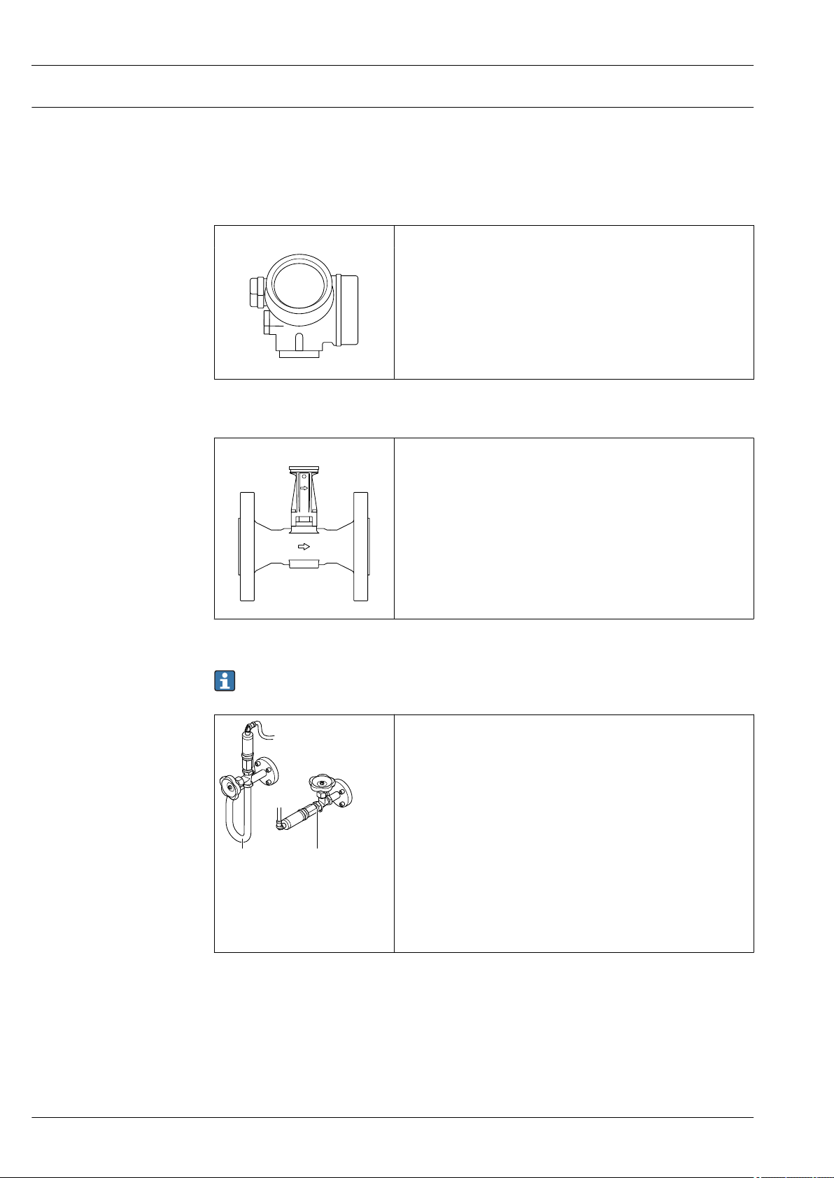
Transmitter
Prowirl 200 Device versions and materials:
• Compact or remote version, aluminum coated:
Aluminum, AlSi10Mg, coated
• Compact or remote version, stainless:
For maximum corrosion resistance: stainless steel CF3M
Configuration:
• Via four-line local display with key operation or via four-line,
illuminated local display with touch control and guided menus ("Make-
A0013471
it-run" wizards) for applications
• Via operating tools (e.g. FieldCare)
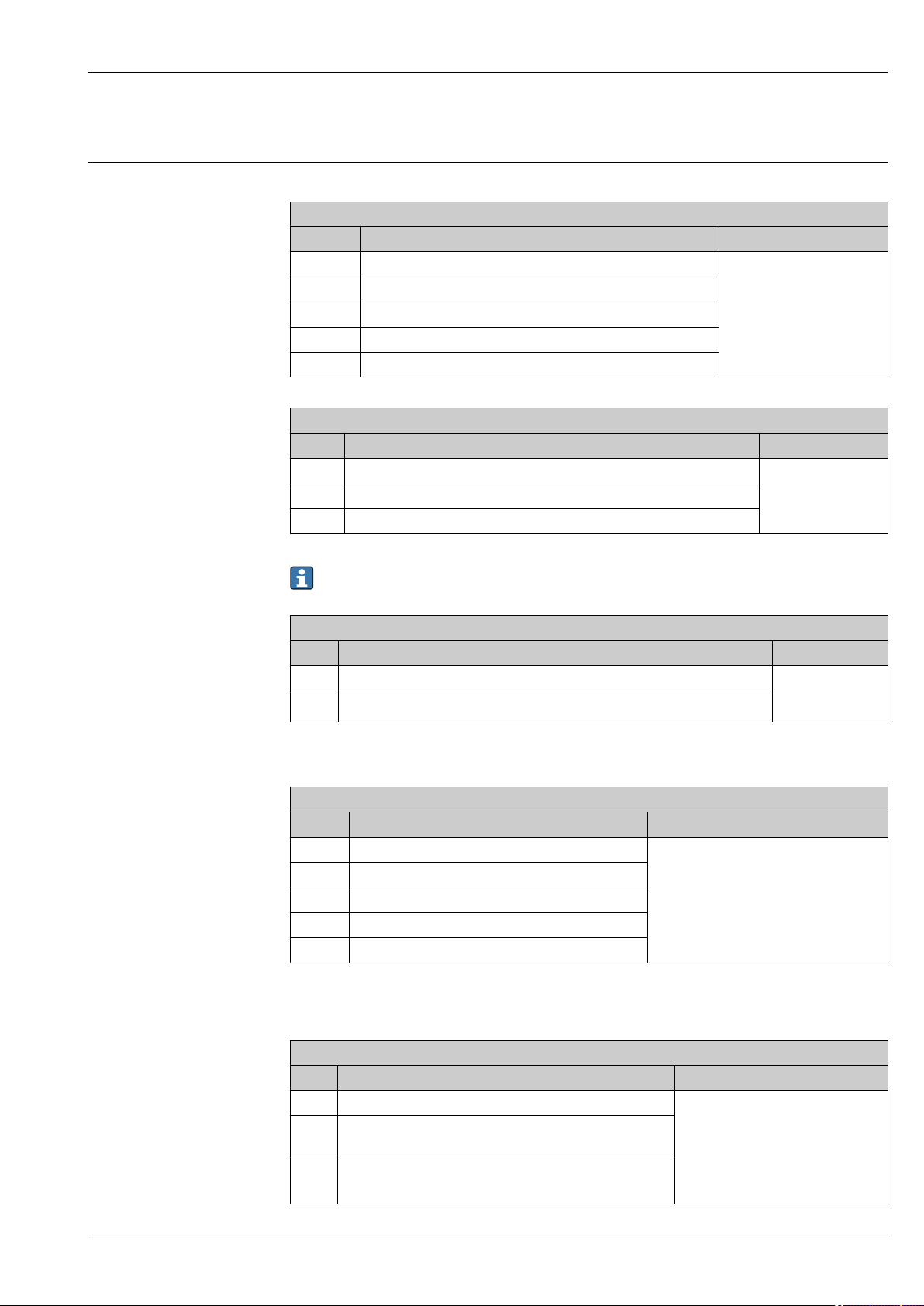
Sensor
ProwirlF Flanged version:
• Nominal diameter range: DN 15 to 300 (½ to 12")
• Materials:
• Measuring tubes
DN 15 to 300 (½ to 12"): stainless cast steel, CF3M/1.4408
DN 15 to 150 (½ to 6"): cast, CX2MW similar to Alloy C22/2.4602
• Flange connections
DN 15 to 300 (½ to 12"): stainless steel, triple-certified material,
1.4404/F316/F316L
• DN 15 to 150 (½ to 6"), pressure ratings up to PN40/Class 300: cast,
CX2MW similar to Alloy C22/2.4602
A0034075
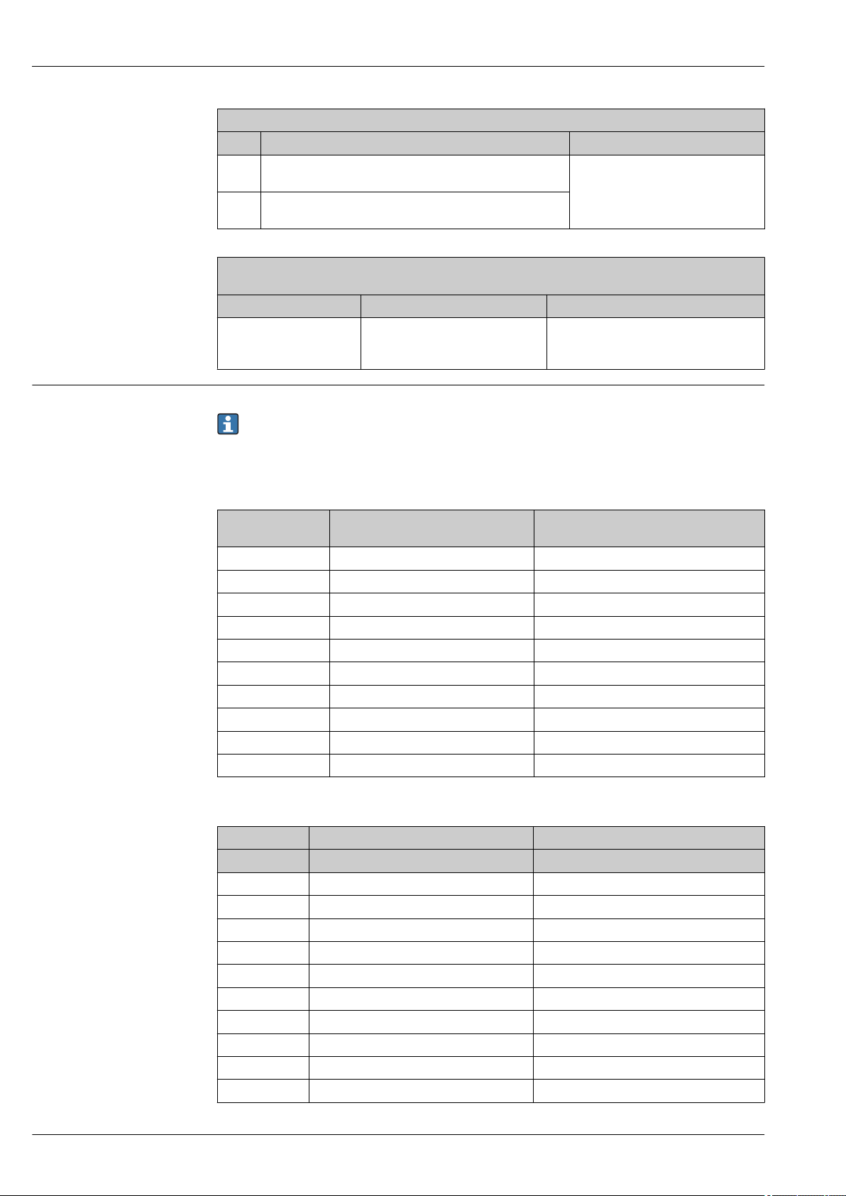
Pressure measuring cell
The "mass" sensor version (integrated pressure/temperature measurement) is available only for
measuring devices in the HART communication mode.
Versions:
Pressure components
• Pressure measuring cell 2 bar_a
• Pressure measuring cell 4 bar_a
• Pressure measuring cell 10 bar_a
• Pressure measuring cell 40 bar_a
• Pressure measuring cell 100 bar_a
Material
• Wetted parts:
A0034080
1 Option DA "mass steam"
2 Option DB "mass gas/liquid"
• Process connection
Stainless steel, 1.4404/316L
• Membrane
Stainless steel, 1.4435/316L
• Non-wetted parts:
Housing
Stainless steel ,1.4404
8 Endress+Hauser
Page 9
Proline Prowirl F 200
Input
Measured variable Direct measured variables
Order code for "Sensor version; DSC sensor; measuring tube"
Option Description Measured variable
AA Volume; 316L; 316L Volume flow
AB Volume; Alloy C22; 316L
AC Volume; Alloy C22; Alloy C22
BA Volume high-temperature; 316L; 316L
BB Volume high-temperature; Alloy C22; 316L
Order code for "Sensor version; DSC sensor; measuring tube"
Option Description Measured variable
CA Mass; 316L; 316L (integrated temperature measurement) • Volume flow
CB Mass; Alloy ; C22; 316L (integrated temperature measurement)
CC Mass; Alloy C22; Alloy C22 (integrated temperature measurement)
• Temperature
The "mass" sensor version (integrated pressure/temperature measurement) is available only for
measuring devices in the HART communication mode.
Order code for "Sensor version; DSC sensor; measuring tube"
Option Description Measured variable
DA Mass steam; 316L; 316L (integrated pressure/temperature measurement) • Volume flow
DB Mass gas/liquid; 316L; 316L (integrated pressure/temperature measurement),
• Temperature
• Pressure
Calculated measured variables
Order code for "Sensor version; DSC sensor; measuring tube"
Option Description Measured variable
AA Volume; 316L; 316L Under constant process conditions:
AB Volume; Alloy C22; 316L
AC Volume; Alloy C22; Alloy C22
BA Volume high-temperature; 316L; 316L
BB Volume high-temperature; Alloy C22; 316L
1) A fixed density must be entered for calculating the mass flow (Setup menu → Advanced setup submenu →
External compensation submenu → Fixed density parameter).
• Mass flow
• Corrected volume flow
The totalized values for:
• Volume flow
• Mass flow
• Corrected volume flow
1)
Order code for "Sensor version; DSC sensor; measuring tube"
Option Description Measured variable
CA Mass; 316L; 316L (integrated temperature measurement) • Corrected volume flow
CB Mass; Alloy C22; 316L (integrated temperature
measurement)
CC Mass; Alloy C22; Alloy C22 (integrated temperature
measurement)
• Mass flow
• Calculated saturated steam pressure
• Energy flow
• Heat flow difference
• Specific volume
• Degrees of superheat
Endress+Hauser 9
Page 10
Proline Prowirl F 200
Order code for "Sensor version; DSC sensor; measuring tube"
Option Description Measured variable
DA Mass steam; 316L; 316L (integrated pressure/temperature
measurement)
DB Mass gas/liquid; 316L; 316L (integrated pressure/
temperature measurement)
Order code for "Sensor version", option "mass flow (integrated temperature measurement)" combined
with order code for "Application package"
Option Description Measured variable
EU Wet steam measurement • Steam quality
• Total mass flow
• Condensate mass flow
Measuring range
The measuring range is dependent on the nominal diameter, the fluid and environmental influences.
The following specified values are the largest possible flow measuring ranges (Q
min
to Q
max
) for
each nominal diameter. Depending on the fluid properties and environmental influences, the
measuring range may be subject to additional restrictions. Additional restrictions apply to both
the lower range value and the upper range value.
Flow measuring ranges in SI units
DN
[mm]
15 0.076 to 4.9 0.39 to 25
25 0.23 to 15 1.2 to 130
40 0.57 to 37 2.9 to 310
50 0.96 to 62 4.9 to 820
80 2.2 to 140 11 to 1 800
100 3.7 to 240 19 to 3 200
150 8.5 to 540 43 to 7 300
200 15 to 950 75 to 13 000
250 23 to 1 500 120 to 20 000
300 33 to 2 100 170 to 28 000
Liquids
[m³/h]
Gas/steam
[m³/h]
Flow measuring ranges in US units
DN Liquids Gas/steam
[in] [ft³/min] [ft³/min]
½ 0.045 to 2.9 0.23 to 15
1 0.14 to 8.8 0.7 to 74
1½ 0.34 to 22 1.7 to 180
2 0.56 to 36 2.9 to 480
3 1.3 to 81 6.4 to 1 100
4 2.2 to 140 11 to 1 900
6 5 to 320 25 to 4 300
8 8.7 to 560 44 to 7 500
10 14 to 880 70 to 12 000
12 19 to 1 300 99 to 17 000
10 Endress+Hauser
Page 11
Proline Prowirl F 200
D
i
v,Q
v [m/s] =
4 · Q [m /h]³
π · D [m]i²
·
1
3600 [s/h]
v [!/s] =
4 · Q [ /min]ft³
π · D [ft]i²
·
1
60 [s/min]
Re
=
4 · Q [m³/s] · [kg/m³]ρ
· D [m] · µ [Pa · s]π
i
Re
=
4 · Q [ft³/s] · [lbm/ft³]ρ
· D [ft] · µ [lbf · s/ft ]π
i
²
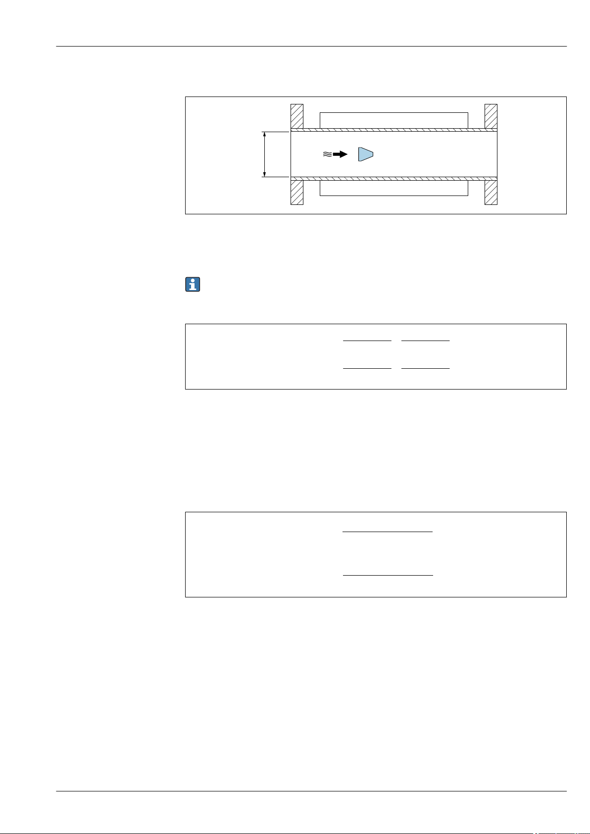
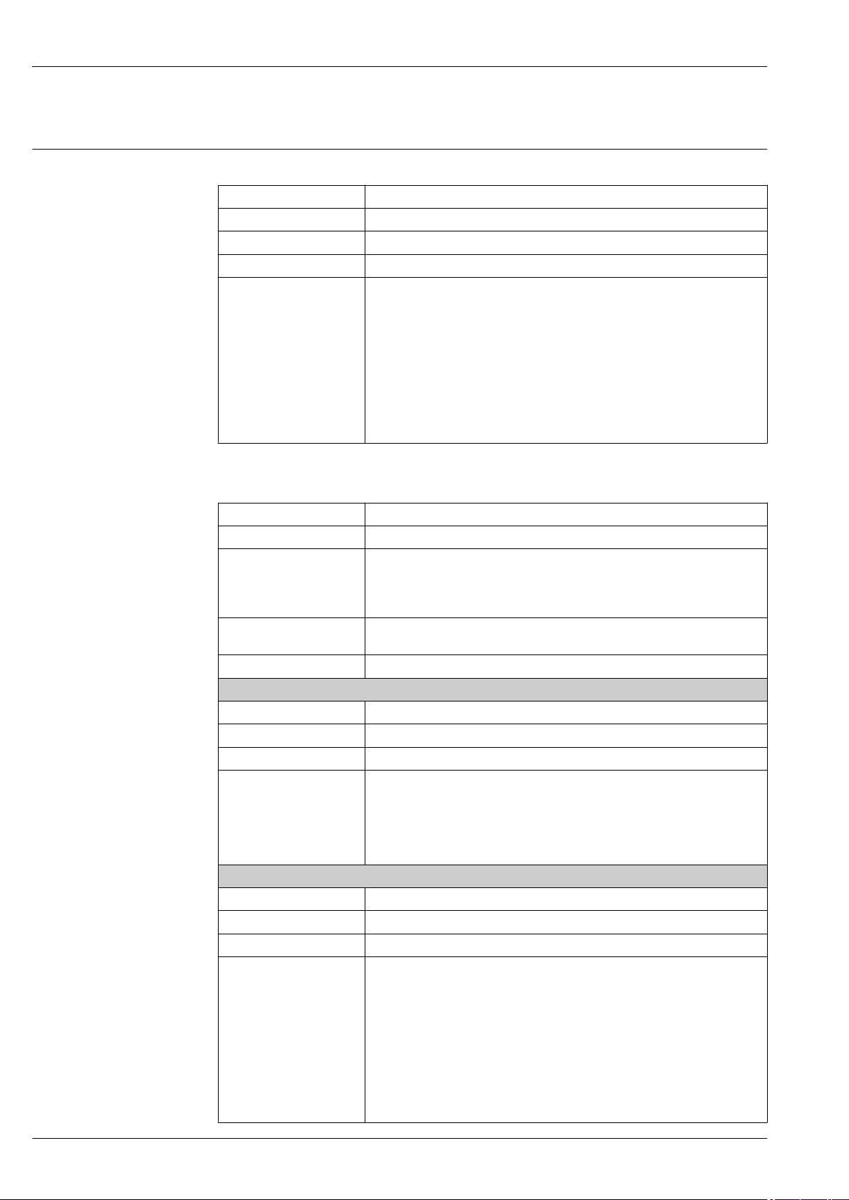
Flow velocity
A0033468
DiInternal diameter of measuring tube (corresponds to dimension K→ 55)
v Velocity in measuring tube
Q Flow
The internal diameter of measuring tube Di is denoted in the dimensions as dimension
K.→ 55.
Calculation of flow velocity:
A0034301
Lower range value
A restriction applies to the lower range value due to the turbulent flow profile, which only occurs
with Reynolds numbers greater than 5 000. The Reynolds number is dimensionless and indicates the
ratio of the inertia force of a fluid to its viscous force when flowing and is used as a characteristic
variable for pipe flows. In the case of pipe flows with Reynolds numbers less than 5 000, periodic
vortices are no longer generated and flow rate measurement is no longer possible.
The Reynolds number is calculated as follows:
A0034291
Re Reynolds number
Q Flow
D
i
µ Dynamic viscosity
ρ Density
Internal diameter of measuring tube (corresponds to dimension K→ 55)
The Reynolds number, 5 000 together with the density and viscosity of the fluid and the nominal
diameter, is used to calculate the corresponding flow rate.
Endress+Hauser 11
Page 12

Proline Prowirl F 200
Q [m /h] =
Re = 5000
³
5000 [Pa· · D [m] · · s]
i
π μ
· 3600 [s/h]
4 [kg/m ]· ³ρ
Q [ /h] =
Re = 5000
!³
5000 [lbf· · D [ft] · · s/ft ]i²π μ
· 60 [s/min]
4 [lbm/ ]· !³ρ
v [m/s] = max
AmpMin
mf [m/s]
x²
v [!/s] = max
AmpMin
mf [!/s]
x²
0.062 [lb/! ]³
ρ [lb/!]³
1 [kg/ ]m³
ρ [kg/ ]m³
⋅
⋅
Q [m /h] =
AmpMin
³
v [m/s]
AmpMin
· · D [m]i²π
· 3600 [s/h]
4 ·
ρ [kg/m ]³
1 [kg/m ]³
Q [ /min] =
AmpMin
!³
v [!/s]
AmpMin
· · D [ft]i²π
· 60 [s/min]
4 ·
ρ [lbm/ ]#³
0.0624 [lbm/ ]!³
A0034302
Q
Re = 5000
D
i
µ Dynamic viscosity
ρ Density
Flow rate is dependent on the Reynolds number
Internal diameter of measuring tube (corresponds to dimension K→ 55)
The measuring signal must have a certain minimum signal amplitude so that the signals can be
evaluated without any errors. Using the nominal diameter, the corresponding flow can also be
derived from this amplitude. The minimum signal amplitude depends on the setting for the
sensitivity of the DSC sensor (s), the steam quality (x) and the force of the vibrations present (a). The
value mf corresponds to the lowest measurable flow velocity without vibration (no wet steam) at a
density of 1 kg/m3 (0.0624 lbm/ft^3). The value mf can be set in the range from
6 to 20 m/s (1.8 to 6 ft/s) (factory setting 12 m/s (3.7 ft/s)) with the Sensitivity parameter (value
range 1 to 9, factory setting 5).
The lowest flow velocity that can be measured on account of the signal amplitude v
AmpMin
is derived
from the Sensitivity parameter and the steam quality (x) or from the force of vibrations present (a).
v
AmpMin
mf Sensitivity
x Steam quality
ρ Density
12 Endress+Hauser
Q
AmpMin
v
AmpMin
Minimum measurable flow velocity based on signal amplitude
Minimum measurable flow rate based on signal amplitude
Minimum measurable flow velocity based on signal amplitude
A0034303
A0034304
Page 13
Proline Prowirl F 200
Q [m /h] = max
Low
³
Q [m /h]
min
³
Q [m /h]
Re = 5000
³
Q [m /h]
AmpMin
³
Q [! /min] = max
Low
³
Q [ /min]
min
!³
Q [ /min]
Re = 5000
!³
Q [ /min]
AmpMin
!³
Q [m /h] =
AmpMax
³
350[m/s] · · D [m]i²π
· 3600 [s/h]
4 ·
ρ [kg/m ]³
1 [kg/m ]³
Q [ /min] =
AmpMax
!³
1148[!/s] · · D [ft]i²π
· 60 [s/min]
4 ·
ρ [lbm/ ]#³
0.0624 [lbm/ ]!³
D
i
Internal diameter of measuring tube (corresponds to dimension K→ 55)
ρ Density
The effective lower range value Q
5000
Q
Low
Q
min
Q
Re = 5000
Q
AmpMin
and Q
.
AmpMin
Effective lower range value
Minimum measurable flow rate
Flow rate is dependent on the Reynolds number
Minimum measurable flow rate based on signal amplitude
is determined using the largest of the three values Q
Low
min
, Q
Re =
A0034313
The Applicator is available for calculation purposes.
Upper range value
The measuring signal amplitude must be below a certain limit value to ensure that the signals can be
evaluated without error. This results in a maximum permitted flow rate Q
Q
AmpMax
D
i
ρ Density
Maximum measurable flow rate based on signal amplitude
Internal diameter of measuring tube (corresponds to dimension K→ 55)
AmpMax
:
A0034316
Endress+Hauser 13
For gas applications, an additional restriction applies to the upper range value with regard to the
Mach number in the measuring device, which must be less than 0.3. The Mach number Ma describes
the ratio of the flow velocity v to the sound velocity c in the fluid.
Page 14

Ma =
v [m/s]
c [m/s]
Ma =
v [!/s]
c [!/s]
Ma Mach number
Q [m /h] =
Ma = 0.3
³
0.3 · c [m/s] · · D [m]i²
π
4
· 3600 [s/h]
Q [ /min] =
Ma = 0.3
!³
0.3 · c [ft/s] · · D [ft]i²
π
4
· 60 [s/min]
Q [m /h] = min
High
³
Q [m /h]
max
³
Q [m /h]
AmpMax
³
Q [m /h]
Ma = 0.3
³
Q [! /min] = min
High
³
Q [ /min]
max
!³
Q [ /min]
AmpMax
!³
Q [ /min]
Ma = 0.3
!³
v
Flow velocity
c Sound velocity
The corresponding flow rate can be derived using the nominal diameter.
Proline Prowirl F 200
A0034321
Q
Ma = 0.3
Restricted upper range value is dependent on Mach number
c Sound velocity
D
i
Internal diameter of measuring tube (corresponds to dimension K→ 55)
ρ Density
The effective upper range value Q
Q
AmpMax
Q
High
Q
max
Q
AmpMax
Q
Ma = 0.3
and Q
Ma=0.3
.
Effective upper range value
Maximum measurable flow rate
Maximum measurable flow rate based on signal amplitude
Restricted upper range value is dependent on Mach number
is determined using the smallest of the three values Q
High
max
A0034337
,
A0034338
For liquids, the occurrence of cavitation may also restrict the upper range value.
The Applicator is available for calculation purposes.
Operable flow range
14 Endress+Hauser
The value, which is typically up to 49: 1, may vary depending on the operating conditions (ratio
between upper range value and lower range value)
Page 15

Proline Prowirl F 200
Input signal Current input
Current input 4-20 mA (passive)
Resolution 1 µA
Voltage drop Typically: 2.2 to 3 V for 3.6 to 22 mA
Maximum voltage ≤ 35 V
Possible input variables • Pressure
External measured values
To increase the accuracy of certain measured variables or to calculate the corrected volume flow, the
automation system can continuously write different measured values to the measuring device:
• Operating pressure to increase accuracy (Endress+Hauser recommends the use of a pressure
measuring device for absolute pressure, e.g. Cerabar M or Cerabar S)
• Medium temperature to increase accuracy (e.g. iTEMP)
• Reference density for calculating the corrected volume flow
• Various pressure measuring devices can be ordered as accessories from Endress+Hauser.
• If using pressure measuring devices, pay attention to outlet runs when installing external
devices→ 46.
If the measuring device does not have pressure or temperature compensation
that external pressure measurement values be read in so that the following measured variables can
be calculated:
• Energy flow
• Mass flow
• Corrected volume flow
• Temperature
• Density
2)
, it is recommended
Integrated pressure and temperature measurement
The measuring device can also directly record external variables for density and energy
compensation.
This product version offers the following benefits:
• Measurement of pressure, temperature and flow in a true 2-wire version
• Recording of pressure and temperature at the same point, thus ensuring maximum accuracy of
density and energy compensation.
• Continuous monitoring of pressure and temperature, thus enabling complete integration in
Heartbeat.
• Easy testing of pressure measurement accuracy:
• Application of pressure by pressure calibration unit, followed by input into measuring device
• Automatic error correction performed by device in the event of a deviation
• Availability of calculated line pressure.
Current input
The measured values are written from the automation system to the measuring device via the
current input → 15.
HART protocol
The measured values are written from the automation system to the measuring device via the HART
protocol. The pressure transmitter must support the following protocol-specific functions:
• HART protocol
• Burst mode
Digital communication
The measured values can be written from the automation system to the measuring via:
• FOUNDATION Fieldbus
• PROFIBUS PA
2) Order code for "Sensor option", option DA, DB
Endress+Hauser 15
Page 16
Output
Output signal Current output
Current output 1 4-20 mA HART (passive)
Current output 2 4-20 mA (passive)
Resolution < 1 µA
Damping Adjustable: 0.0 to 999.9 s
Assignable measured
variables
Proline Prowirl F 200
• Volume flow
• Corrected volume flow
• Mass flow
• Flow velocity
• Temperature
• Pressure
• Calculated saturated steam pressure
• Steam quality
• Total mass flow
• Energy flow
• Heat flow difference
Pulse/frequency/switch output
Function Can be set to pulse, frequency or switch output
Version Passive, open collector
Maximum input values • DC 35 V
• 50 mA
For information on the Ex connection values → 19
Voltage drop • For ≤ 2 mA: 2 V
• For 10 mA: 8 V
Residual current ≤ 0.05 mA
Pulse output
Pulse width Adjustable: 5 to 2 000 ms
Maximum pulse rate 100 Impulse/s
Pulse value Adjustable
Assignable measured
variables
Frequency output
Output frequency Adjustable: 0 to 1 000 Hz
Damping Adjustable: 0 to 999 s
Pulse/pause ratio 1:1
Assignable measured
variables
• Mass flow
• Volume flow
• Corrected volume flow
• Total mass flow
• Energy flow
• Heat flow difference
• Volume flow
• Corrected volume flow
• Mass flow
• Flow velocity
• Temperature
• Calculated saturated steam pressure
• Steam quality
• Total mass flow
• Energy flow
• Heat flow difference
• Pressure
16 Endress+Hauser
Page 17
Proline Prowirl F 200
Switch output
Switching behavior Binary, conductive or non-conductive
Switching delay Adjustable: 0 to 100 s
Number of switching
cycles
Assignable functions • Off
Unlimited
• On
• Diagnostic behavior
• Limit value
• Volume flow
• Corrected volume flow
• Mass flow
• Flow velocity
• Temperature
• Calculated saturated steam pressure
• Steam quality
• Total mass flow
• Energy flow
• Heat flow difference
• Pressure
• Reynolds number
• Totalizer 1-3
• Status
• Status of low flow cut off
Signal on alarm
FOUNDATION Fieldbus
FOUNDATION Fieldbus H1, IEC 61158-2, galvanically isolated
Data transfer 31.25 kbit/s
Current consumption 15 mA
Permitted supply voltage 9 to 32 V
Bus connection With integrated reverse polarity protection
PROFIBUS PA
PROFIBUS PA In accordance with EN 50170 Volume 2, IEC 61158-2 (MBP), galvanically
isolated
Data transmission 31.25 kbit/s
Current consumption 16 mA
Permitted supply voltage 9 to 32 V
Bus connection With integrated reverse polarity protection
Depending on the interface, failure information is displayed as follows:
Current output 4 to 20 mA
4 to 20 mA
Failure mode Choose from:
• 4 to 20 mA in accordance with NAMUR recommendation NE 43
• 4 to 20 mA in accordance with US
• Min. value: 3.59 mA
• Max. value: 22.5 mA
• Freely definable value between: 3.59 to 22.5 mA
• Actual value
• Last valid value
Endress+Hauser 17
Page 18
Pulse/frequency/switch output
Pulse output
Failure mode No pulses
Frequency output
Failure mode Choose from:
• Actual value
• 0 Hz
• Defined value: 0 to 1 250 Hz
Switch output
Failure mode Choose from:
• Current status
• Open
• Closed
FOUNDATION Fieldbus
Proline Prowirl F 200
Status and alarm
messages
Failure current FDE (Fault
Disconnection Electronic)
Diagnostics in accordance with FF-891
0 mA
PROFIBUS PA
Status and alarm
messages
Failure current FDE (Fault
Disconnection Electronic)
Diagnostics in accordance with PROFIBUS PA Profile 3.02
0 mA
Local display
Plain text display With information on cause and remedial measures
Backlight Additionally for device version with SD03 local display: red lighting indicates a
device error.
Status signal as per NAMUR recommendation NE 107
Interface/protocol
• Via digital communication:
• HART protocol
• FOUNDATION Fieldbus
• PROFIBUS PA
• Via service interface
CDI service interface
Plain text display With information on cause and remedial measures
Additional information on remote operation → 85
Load
Load for current output: 0 to 500 Ω, depending on the external supply voltage of the power supply
unit
18 Endress+Hauser
Page 19
Proline Prowirl F 200
0
100
200
300
400
500
16 18 20
22 24
26 28 30 32
U [V]
S
RB[Ω]
34 36
A B
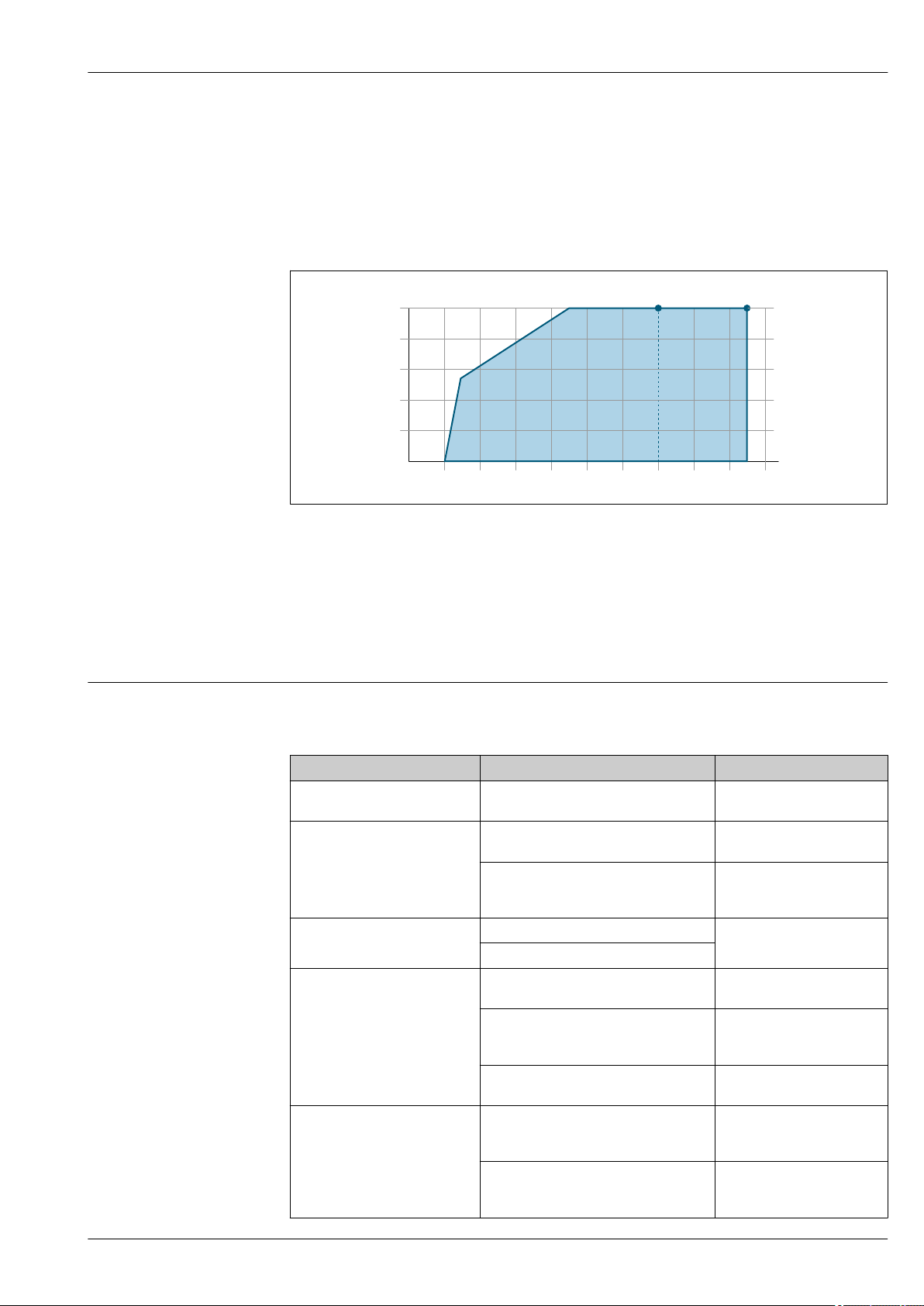
Calculation of the maximum load
Depending on the supply voltage of the power supply unit (US), the maximum load (RB) including
line resistance must be observed to ensure adequate terminal voltage at the device. In doing so,
observe the minimum terminal voltage
• For US = 17.9 to 18.9 V: RB ≤ (US - 17.9 V): 0.0036 A
• For US = 18.9 to 24 V: RB ≤ (US - 13 V): 0.022 A
• For US = ≥ 24 V: RB ≤ 500 Ω
A Operating range for order code for "Output", option A "4-20 mA HART"/option B "4-20 mA HART, pulse/
frequency/switch output" with Ex i and option C "4-20 mA HART + 4-20 mA analog"
B Operating range for order code for "Output", option A "4-20 mA HART"/option B "4-20 mA HART, pulse/
frequency/switch output" with non-Ex and Ex d
Sample calculation
Supply voltage of power supply unit: US =19 V
Maximum load: RB ≤ (19 V - 13 V): 0.022 A = 273 Ω
Ex connection data Safety-related values
Type of protection Ex d
Order code for "Output" Output type Safety-related values
Option A 4-20mA HART U
Option B 4-20mA HART U
Option C 4-20mA HART
Option D 4-20mA HART U
Option E FOUNDATION Fieldbus U
Pulse/frequency/switch output U
4-20mA analog
Pulse/frequency/switch output U
4 to 20 mA current input U
Pulse/frequency/switch output U
nom
U
max
nom
U
max
nom
U
max
P
max
U
nom
U
max
nom
U
max
nom
U
max
P
max
nom
U
max
nom
U
max
P
max
nom
U
max
P
max
= DC 35 V
= 250 V
= DC 35 V
= 250 V
= DC 35 V
= 250 V
1)
= 1 W
= DC 30 V
= 250 V
= DC 35 V
= 250 V
= DC 35 V
= 250 V
1)
= 1 W
= DC 35 V
= 250 V
= DC 32 V
= 250 V
= 0.88 W
= DC 35 V
= 250 V
1)
= 1 W
A0013563
Endress+Hauser 19
Page 20
Proline Prowirl F 200
Order code for "Output" Output type Safety-related values
Option G PROFIBUS PA U
Pulse/frequency/switch output U
1) Internal circuit limited by Ri = 760.5 Ω
Type of protection Ex ec Ex nA
Order code for "Output" Output type Safety-related values
Option A 4-20mA HART U
Option B 4-20mA HART U
Pulse/frequency/switch output U
Option C 4-20mA HART
4-20mA analog
Option D 4-20mA HART U
Pulse/frequency/switch output U
4 to 20 mA current input U
Option E FOUNDATION Fieldbus U
Pulse/frequency/switch output U
Option G PROFIBUS PA U
Pulse/frequency/switch output U
nom
U
max
P
max
nom
U
max
P
max
nom
U
max
nom
U
max
nom
U
max
P
max
U
nom
U
max
nom
U
max
nom
U
max
P
max
nom
U
max
nom
U
max
P
max
nom
U
max
P
max
nom
U
max
P
max
nom
U
max
P
max
= DC 32 V
= 250 V
= 0.88 W
= DC 35 V
= 250 V
1)
= 1 W
= DC 35 V
= 250 V
= DC 35 V
= 250 V
= DC 35 V
= 250 V
1)
= 1 W
= DC 30 V
= 250 V
= DC 35 V
= 250 V
= DC 35 V
= 250 V
= 1 W
= DC 35 V
= 250 V
= DC 32 V
= 250 V
= 0.88 W
= DC 35 V
= 250 V
= 1 W
= DC 32 V
= 250 V
= 0.88 W
= DC 35 V
= 250 V
= 1 W
1) Internal circuit limited by Ri = 760.5 Ω
Type of protection XP
Order code for "Output" Output type Safety-related values
Option A 4-20mA HART U
Option B 4-20mA HART U
Pulse/frequency/switch output U
Option C 4-20mA HART U
nom
U
max
nom
U
max
nom
U
max
P
max
nom
U
max
= DC 35 V
= 250 V
= DC 35 V
= 250 V
= DC 35 V
= 250 V
1)
= 1 W
= DC 30 V
= 250 V
20 Endress+Hauser
Page 21

Proline Prowirl F 200
Order code for "Output" Output type Safety-related values
4-20mA analog
Option D 4-20mA HART U
Pulse/frequency/switch output U
4 to 20 mA current input U
Option E FOUNDATION Fieldbus U
Pulse/frequency/switch output U
Option G PROFIBUS PA U
Pulse/frequency/switch output U
nom
U
max
nom
U
max
P
max
nom
U
max
nom
U
max
P
max
nom
U
max
P
max
nom
U
max
P
max
nom
U
max
P
max
= DC 35 V
= 250 V
= DC 35 V
= 250 V
1)
= 1 W
= DC 35 V
= 250 V
= DC 32 V
= 250 V
= 0.88 W
= DC 35 V
= 250 V
1)
= 1 W
= DC 32 V
= 250 V
= 0.88 W
= DC 35 V
= 250 V
1)
= 1 W
1) Internal circuit limited by Ri = 760.5 Ω
Intrinsically safe values
Type of protection Ex ia
Order code for "Output" Output type Intrinsically safe values
Option A 4-20mA HART Ui = DC 30 V
Ii = 300 mA
Pi = 1 W
Li = 0 μH
Ci = 5 nF
Option B 4-20mA HART Ui = DC 30 V
Ii = 300 mA
Pi = 1 W
Li = 0 μH
Ci = 5 nF
Pulse/frequency/switch output Ui = DC 30 V
Ii = 300 mA
Pi = 1 W
Li = 0 μH
Ci = 6 nF
Option C 4-20mA HART Ui = DC 30 V
4-20mA analog
Ii = 300 mA
Pi = 1 W
Li = 0 μH
Ci = 30 nF
Endress+Hauser 21
Page 22

Proline Prowirl F 200
Order code for "Output" Output type Intrinsically safe values
Option D 4-20mA HART Ui = DC 30 V
Ii = 300 mA
Pi = 1 W
Li = 0 μH
Ci = 5 nF
Pulse/frequency/switch output Ui = DC 30 V
Ii = 300 mA
Pi = 1 W
Li = 0 μH
Ci = 6 nF
4 to 20 mA current input Ui = DC 30 V
Ii = 300 mA
Pi = 1 W
Li = 0 μH
Ci = 5 nF
Option E FOUNDATION Fieldbus STANDARD
Ui = 30 V
li = 300 mA
Pi = 1.2 W
Li = 10 µH
Ci = 5 nF
Pulse/frequency/switch output Ui = 30 V
li = 300 mA
Pi = 1 W
Li = 0 µH
Ci = 6 nF
Option G PROFIBUS PA STANDARD
Ui = 30 V
li = 300 mA
Pi = 1.2 W
Li = 10 µH
Ci = 5 nF
Pulse/frequency/switch output Ui = 30 V
li = 300 mA
Pi = 1 W
Li = 0 µH
Ci = 6 nF
FISCO
Ui = 17.5 V
li = 550 mA
Pi = 5.5 W
Li = 10 µH
Ci = 5 nF
FISCO
Ui = 17.5 V
li = 550 mA
Pi = 5.5 W
Li = 10 µH
Ci = 5 nF
Type of protection Ex ic
Order code for "Output" Output type Intrinsically safe values
Option A 4-20mA HART Ui = DC 35 V
Ii = n.a.
Pi = 1 W
Li = 0 μH
Ci = 5 nF
Option B 4-20mA HART Ui = DC 35 V
Ii = n.a.
Pi = 1 W
Li = 0 μH
Ci = 5 nF
Pulse/frequency/switch output Ui = DC 35 V
Ii = n.a.
Pi = 1 W
Li = 0 μH
Ci = 6 nF
Option C 4-20mA HART Ui = DC 30 V
4-20mA analog
Ii = n.a.
Pi = 1 W
Li = 0 μH
Ci = 30 nF
22 Endress+Hauser
Page 23

Proline Prowirl F 200
Order code for "Output" Output type Intrinsically safe values
Option D 4-20mA HART Ui = DC 35 V
Ii = n.a.
Pi = 1 W
Li = 0 μH
Ci = 5 nF
Pulse/frequency/switch output Ui = DC 35 V
Ii = n.a.
Pi = 1 W
Li = 0 μH
Ci = 6 nF
4 to 20 mA current input Ui = DC 35 V
Ii = n.a.
Pi = 1 W
Li = 0 μH
Ci = 5 nF
Option E FOUNDATION Fieldbus STANDARD
Ui = 32 V
li = 300 mA
Pi = n.a.
Li = 10 µH
Ci = 5 nF
Pulse/frequency/switch output Ui = 35 V
li = 300 mA
Pi = 1 W
Li = 0 µH
Ci = 6 nF
Option G PROFIBUS PA STANDARD
Ui = 32 V
li = 300 mA
Pi = n.a.
Li = 10 µH
Ci = 5 nF
Pulse/frequency/switch output Ui = 35 V
li = 300 mA
Pi = 1 W
Li = 0 µH
Ci = 6 nF
FISCO
Ui = 17.5 V
li = n.a.
Pi = n.a.
Li = 10 µH
Ci = 5 nF
FISCO
Ui = 17.5 V
li = n.a.
Pi = n.a.
Li = 10 µH
Ci = 5 nF
Type of protection IS
Order code for "Output" Output type Intrinsically safe values
Option A 4-20mA HART Ui = DC 30 V
Ii = 300 mA
Pi = 1 W
Li = 0 μH
Ci = 5 nF
Option B 4-20mA HART Ui = DC 30 V
Ii = 300 mA
Pi = 1 W
Li = 0 μH
Ci = 5 nF
Pulse/frequency/switch output Ui = DC 30 V
Ii = 300 mA
Pi = 1 W
Li = 0 μH
Ci = 6 nF
Option C 4-20mA HART Ui = DC 30 V
4-20mA analog
Ii = 300 mA
Pi = 1 W
Li = 0 μH
Ci = 30 nF
Endress+Hauser 23
Page 24

Proline Prowirl F 200
Order code for "Output" Output type Intrinsically safe values
Option D 4-20mA HART Ui = DC 30 V
Ii = 300 mA
Pi = 1 W
Li = 0 μH
Ci = 5 nF
Pulse/frequency/switch output Ui = DC 30 V
Ii = 300 mA
Pi = 1 W
Li = 0 μH
Ci = 6 nF
4 to 20 mA current input Ui = DC 30 V
Ii = 300 mA
Pi = 1 W
Li = 0 μH
Ci = 5 nF
Option E FOUNDATION Fieldbus STANDARD
Ui = 30 V
li = 300 mA
Pi = 1.2 W
Li = 10 µH
Ci = 5 nF
Pulse/frequency/switch output Ui = 30 V
li = 300 mA
Pi = 1 W
Li = 0 µH
Ci = 6 nF
Option G PROFIBUS PA STANDARD
Ui = 30 V
li = 300 mA
Pi = 1.2 W
Li = 10 µH
Ci = 5 nF
Pulse/frequency/switch output Ui = 30 V
li = 300 mA
Pi = 1 W
Li = 0 µH
Ci = 6 nF
FISCO
Ui = 17.5 V
li = 550 mA
Pi = 5.5 W
Li = 10 µH
Ci = 5 nF
FISCO
Ui = 17.5 V
li = 550 mA
Pi = 5.5 W
Li = 10 µH
Ci = 5 nF
Low flow cut off
Galvanic isolation
The switch points for low flow cut off are preset and can be configured.
All inputs and outputs are galvanically isolated from one another.
Protocol-specific data HART
Manufacturer ID 0x11
Device type ID 0x0038
HART protocol revision 7
Device description files
(DTM, DD)
HART load • Min. 250 Ω
System integration For information on system integration, see Operating Instructions.→ 96
Information and files under:
www.endress.com
• Max. 500 Ω
• Measured variables via HART protocol
• Burst Mode functionality
24 Endress+Hauser
Page 25

Proline Prowirl F 200
FOUNDATION Fieldbus
Manufacturer ID 0x452B48
Ident number 0x1038
Device revision 2
DD revision Information and files under:
CFF revision
Device Tester Version (ITK
version)
ITK Test Campaign Number Information:
Link Master capability (LAS) Yes
Choice of "Link Master" and
"Basic Device"
Node address Factory setting: 247 (0xF7)
Supported functions The following methods are supported:
Virtual Communication Relationships (VCRs)
Number of VCRs 44
Number of link objects in VFD 50
Permanent entries 1
Client VCRs 0
Server VCRs 10
Source VCRs 43
Sink VCRs 0
Subscriber VCRs 43
Publisher VCRs 43
Device Link Capabilities
Slot time 4
Min. delay between PDU 8
Max. response delay Min. 5
System integration For information on system integration, see Operating Instructions.→ 96
• www.endress.com
• www.fieldbus.org
6.2.0
• www.endress.com
• www.fieldbus.org
Yes
Factory setting: Basic Device
• Restart
• ENP Restart
• Diagnostic
• Read events
• Read trend data
• Cyclic data transmission
• Description of the modules
• Execution times
• Methods
PROFIBUS PA
Manufacturer ID 0x11
Ident number 0x1564
Profile version 3.02
Device description files (GSD,
DTM, DD)
Information and files under:
• www.endress.com
• www.profibus.org
Endress+Hauser 25
Page 26
Supported functions • Identification & Maintenance
3 4 1 2
4
5 6
+ – + –+ –
123
Configuration of the device
address
System integration For information on system integration, see Operating Instructions.→ 96
Power supply
Terminal assignment Transmitter
Proline Prowirl F 200
Simple device identification via control system and nameplate
• PROFIBUS upload/download
Reading and writing parameters is up to ten times faster with PROFIBUS
upload/download
• Condensed status
Simplest and self-explanatory diagnostic information by categorizing
diagnostic messages that occur
• DIP switches on the I/O electronics module
• Local display
• Via operating tools (e. g. FieldCare)
• Cyclic data transmission
• Block model
• Description of the modules
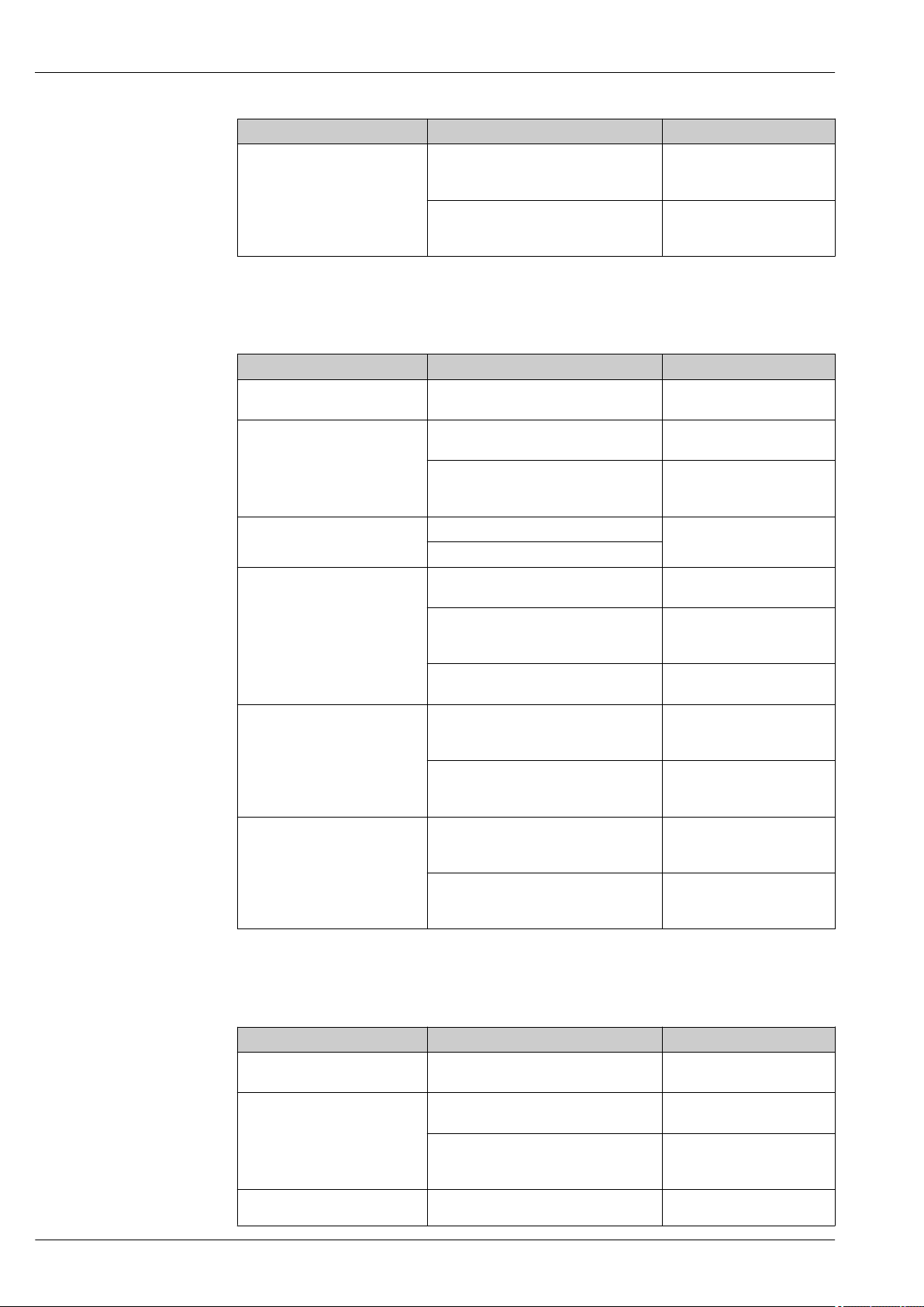
Connection versions
Maximum number of terminals
Terminals 1 to 6:
Without integrated overvoltage protection
1
Output 1 (passive): supply voltage and signal transmission
2
Output 2 (passive): supply voltage and signal transmission
3
Input (passive): supply voltage and signal transmission
4
Ground terminal for cable shield
Order code for "Output" Terminal numbers
Output 1 Output 2 Input
1 (+) 2 (-) 3 (+) 4 (-) 5 (+) 6 (-)
Option A 4-20 mA HART (passive) - -
Option B
Option C
Option D
1)
1)
1) 2)
4-20 mA HART (passive)
4-20 mA HART (passive) 4-20 mA analog (passive) -
4-20 mA HART (passive)
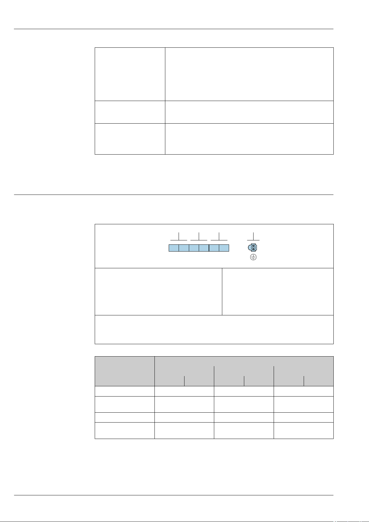
Maximum number of terminals for order code for
"Accessory mounted", option NA "Overvoltage
protection"
• Terminals 1 to 4:
With integrated overvoltage protection
• Terminals 5 to 6:
Without integrated overvoltage protection
Pulse/frequency/switch
output (passive)
Pulse/frequency/switch
output (passive)
A0033475
-
4-20 mA current input
(passive)
26 Endress+Hauser
Page 27
Proline Prowirl F 200
+ –
+ –
2
1
1
2
1 2 3 4
1 2 3 4
GNYEWHBN
Order code for "Output" Terminal numbers
Output 1 Output 2 Input
1 (+) 2 (-) 3 (+) 4 (-) 5 (+) 6 (-)
Option E
Option G
1) Output 1 must always be used; output 2 is optional.
2) The integrated overvoltage protection is not used with option D: Terminals 5 and 6 (current input) are not
protected against overvoltage.
3) FOUNDATION Fieldbus with integrated reverse polarity protection.
4) PROFIBUS PA with integrated reverse polarity protection.
1) 3)
1) 4)
FOUNDATION Fieldbus
PROFIBUS PA
Pulse/frequency/switch
output (passive)
Pulse/frequency/switch
output (passive)
-
-
Connecting cable for remote version
Transmitter and sensor connection housing
In the case of the remote version, the sensor and transmitter are mounted separately from on
another and connected by a connecting cable. Connection is performed via the sensor connection
housing and the transmitter housing.
How the connecting cable is connected in the transmitter housing depends on the measuring
device approval and the version of the connecting cable used.
In the following versions, only terminals can be used for connection in the transmitter housing:
• Certain approvals: Ex nA, Ex ec, Ex tb and Division 1
• Use of reinforced connecting cable
• Order code for "Sensor version; DSC sensor; measuring tube", option DA, DB
In the following versions, an M12 device connector is used for connection in the transmitter
housing:
• All other approvals
• Use of connecting cable (standard)
Terminals are always used to connect the connecting cable in the sensor connection housing
(tightening torques for screws for cable strain relief: 1.2 to 1.7 Nm).
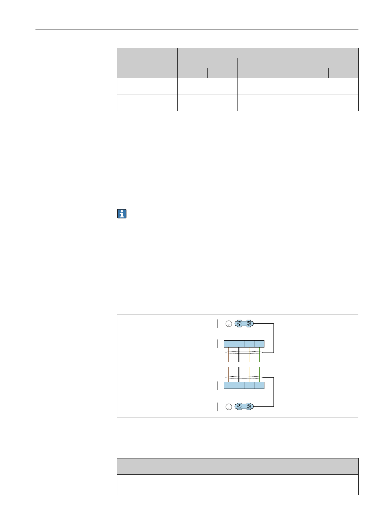
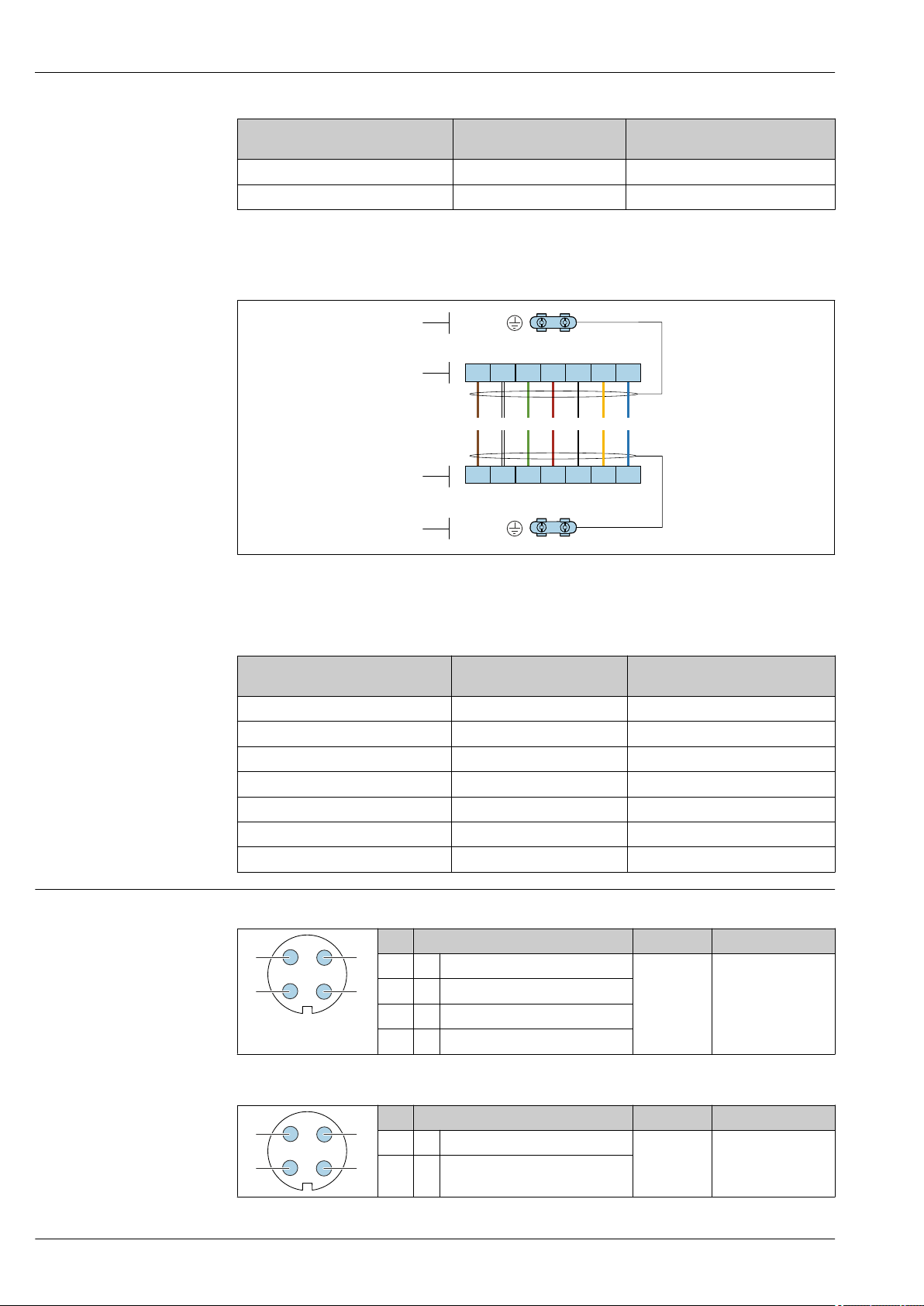
Connecting cable (standard, reinforced)
A0033476
2 Terminals for connection compartment in the transmitter wall holder and the sensor connection housing
1 Terminals for connecting cable
2 Grounding via the cable strain relief
Terminal number Assignment Cable color
Connecting cable
1 Supply voltage Brown
2 Grounding White
Endress+Hauser 27
Page 28
Terminal number Assignment Cable color
+–
+ –
2
1
1
2
1 2 3 4
1 2 3 4556677
RDGNWHBN BK YE BU
+–
+ –
RES
VCC
GND
RES
VCC
GND
1
2
4
3
1
2
4
3
3 RS485 (+) Yellow
4 RS485 (–) Green
Connecting cable (option "mass pressure-/temperature-compensated")
Order code for "Sensor version; DSC sensor; measuring tube", option DA, DB
Proline Prowirl F 200
Connecting cable
3 Terminals for connection compartment in the transmitter wall holder and the sensor connection housing
1 Terminals for connecting cable
2 Grounding via the cable strain relief
Terminal number Assignment Cable color
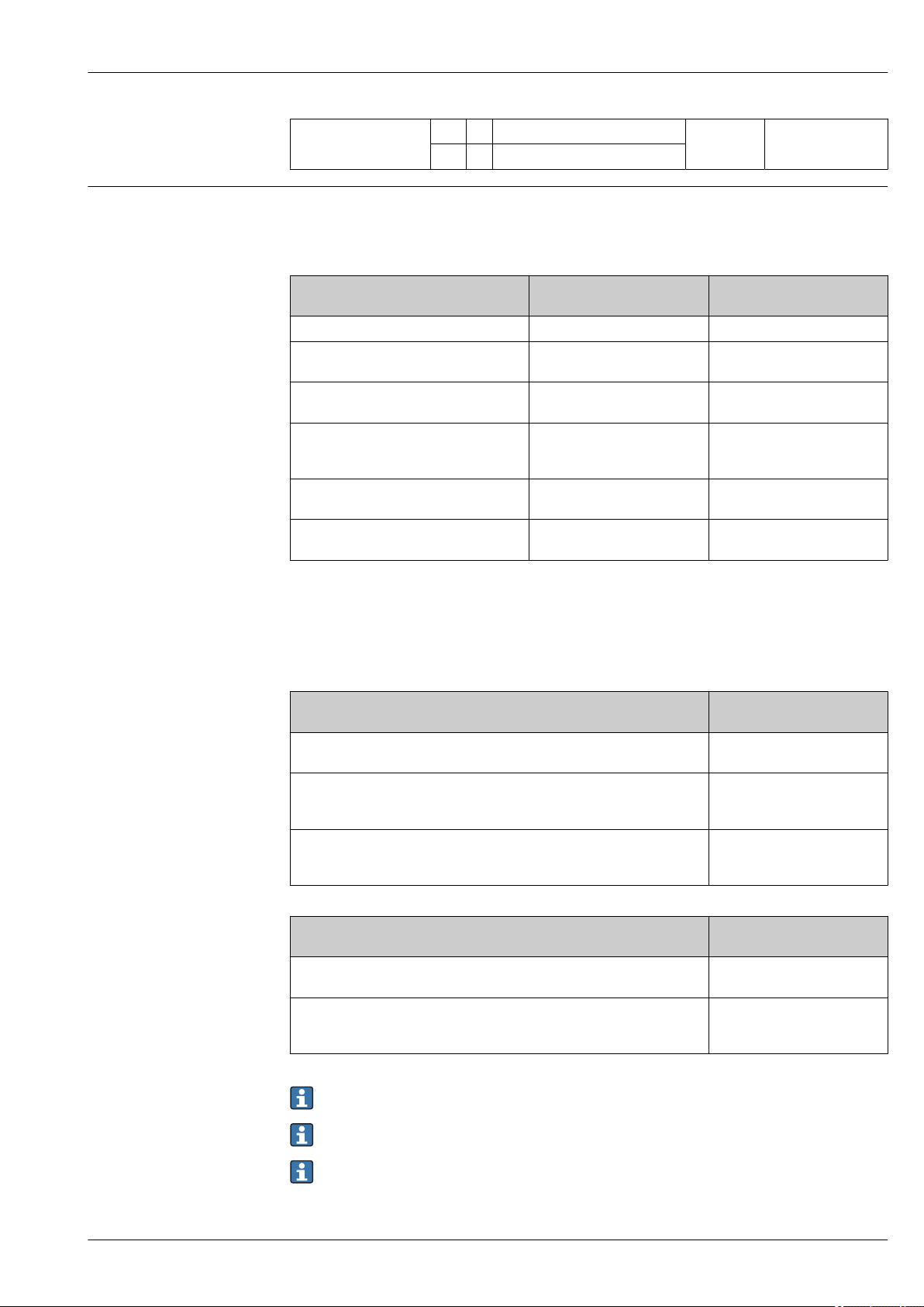
Pin assignment, device plug PROFIBUS PA
A0034571
Connecting cable
1 RS485 (-) DPC Brown
2 RS485 (+) DPC White
3 Reset Green
4 Supply voltage red
5 Grounding Black
6 RS485 (+) Yellow
7 RS485 (–) Blue
Pin Assignment Coding Plug/socket
1 + PROFIBUS PA + A Plug
2 Grounding
3 - PROFIBUS PA –
4 Not assigned
28 Endress+Hauser
FOUNDATION Fieldbus
Pin Assignment Coding Plug/socket
1 + Signal + A Plug
2 - Signal –
Page 29
Proline Prowirl F 200
Supply voltage Transmitter
An external power supply is required for each output.
3 Grounding
4 Not assigned
Supply voltage for a compact version without a local display
Order code for "Output; input" Minimum
terminal voltage
Option A: 4-20 mA HART ≥ DC 12 V DC 35 V
Option B: 4-20 mA HART, pulse/
frequency/switch output
Option C: 4-20 mA HART + 4-20 mA
analog
Option D: 4-20 mA HART, pulse/
frequency/switch output, 4-20 mA current
3)
input
Option E: FOUNDATION Fieldbus, pulse/
frequency/switch output
Option G: PROFIBUS PA, pulse/frequency/
switch output
1) In event of external supply voltage of the power supply unit with load, the PROFIBUS DP/PA coupler or
FOUNDATION Fieldbus power conditioners
2) The minimum terminal voltage increases if local operation is used: see the following table
3) Voltage drop 2.2 to 3 V for 3.59 to 22 mA
1)
2)
≥ DC 12 V DC 35 V
≥ DC 12 V DC 30 V
≥ DC 12 V DC 35 V
≥ DC 9 V DC 32 V
≥ DC 9 V DC 32 V
Maximum
terminal voltage
Increase in minimum terminal voltage
Order code for "Display; operation"
Option C:
Local operation SD02
Option E:
Local operation SD03 with lighting
(backlighting not used)
Option E:
Local operation SD03 with lighting
(backlighting used)
Increase in minimum
terminal voltage
+ DC 1 V
+ DC 1 V
+ DC 3 V
Order code for "Sensor version; DSC sensor; measuring tube"
Option DA:
Mass steam; 316L; 316L (integrated pressure/temperature measurement)
Option DB:
Mass gas/liquid; 316L; 316L (integrated pressure/temperature
measurement)
Increase in minimum
terminal voltage
+ DC 1 V
+ DC 1 V
For information about the load see → 18
Various power supply units can be ordered from Endress+Hauser: → 95
For information on the Ex connection values → 19
Endress+Hauser 29
Page 30
Power consumption Transmitter
Order code for "Output; input" Maximum power consumption
Option A: 4-20 mA HART 770 mW
Option B: 4-20 mA HART, pulse/
frequency/switch output
Option C: 4-20 mA HART + 4-20 mA
analog
Option D: 4-20 mA HART, pulse/
frequency/switch output, 4-20 mA current
input
Option E: FOUNDATION Fieldbus, pulse/
frequency/switch output
Option G: PROFIBUS PA, pulse/frequency/
switch output
For information on the Ex connection values → 19
Proline Prowirl F 200
• Operation with output 1: 770 mW
• Operation with output 1 and 2: 2 770 mW
• Operation with output 1: 660 mW
• Operation with output 1 and 2: 1 320 mW
• Operation with output 1: 770 mW
• Operation with output 1 and 2: 2770 mW
• Operation with output 1 and input: 840 mW
• Operation with output 1, 2 and input: 2840 mW
• Operation with output 1: 512 mW
• Operation with output 1 and 2: 2 512 mW
• Operation with output 1: 512 mW
• Operation with output 1 and 2: 2 512 mW
Current consumption Current output
For every 4-20 mA or 4-20 mA HART current output: 3.6 to 22.5 mA
If the option Defined value is selected in the Failure mode parameter : 3.59 to 22.5 mA
Current input
3.59 to 22.5 mA
Internal current limiting: max. 26 mA
FOUNDATION Fieldbus
15 mA
PROFIBUS PA
15 mA
Power supply failure
• Totalizers stop at the last value measured.
• Depending on the device version, the configuration is retained in the device memoryor in the
pluggable data memory (HistoROM DAT).
• Error messages (incl. total operated hours) are stored.
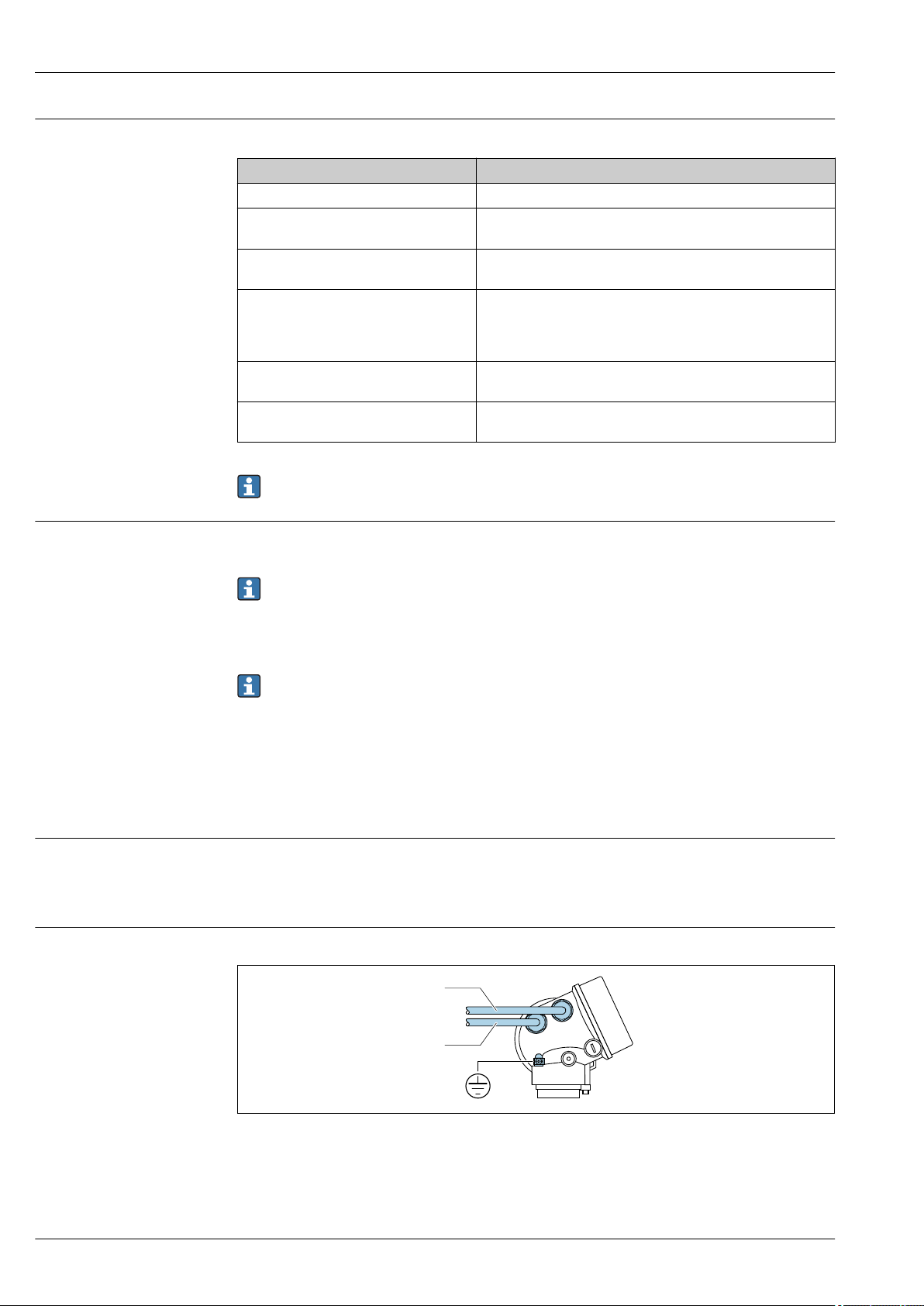
Electrical connection Connecting the transmitter
A0033480
1 Cable entries for inputs/outputs
30 Endress+Hauser
Page 31

Proline Prowirl F 200
3
1
2
2
3
4...20 mA
41
5
Remote version connection
Connecting cable
A0033481
4 Connecting cable connection
1 Wall holder with connection compartment (transmitter)
2 Connecting cable
3 Sensor connection housing
How the connecting cable is connected in the transmitter housing depends on the measuring
device approval and the version of the connecting cable used.
In the following versions, only terminals can be used for connection in the transmitter housing:
• Certain approvals: Ex nA, Ex ec, Ex tb and Division 1
• Use of reinforced connecting cable
• Order code for "Sensor version; DSC sensor; measuring tube", option DA, DB
In the following versions, an M12 device connector is used for connection in the transmitter
housing:
• All other approvals
• Use of connecting cable (standard)
Terminals are always used to connect the connecting cable in the sensor connection housing
(tightening torques for screws for cable strain relief: 1.2 to 1.7 Nm).
Connection examples
Current output 4-20 mA HART
A0028762
5 Connection example for 4 to 20 mA HART current output (passive)
1 Automation system with current input (e.g. PLC)
2 Power supply
3 Cable shield provided at one end. The cable shield must be grounded at both ends to comply with EMC
requirements; observe cable specifications
4 Analog display unit: observe maximum load
5 Transmitter
Endress+Hauser 31
Page 32

Pulse/frequency output
1
2
3
12345
1
2
3
6 Connection example for pulse/frequency output (passive)
1 Automation system with pulse/frequency input (e.g. PLC)
2 Power supply
3 Transmitter: Observe input values
Switch output
Proline Prowirl F 200
A0028761
7 Connection example for switch output (passive)
1 Automation system with switch input (e.g. PLC)
2 Power supply
3 Transmitter: Observe input values
A0028760
32 Endress+Hauser
Page 33

Proline Prowirl F 200
21 3 4
78
6 6
6
6
5
6
6
5
FOUNDATION Fieldbus
8 Connection example for FOUNDATION Fieldbus
1 Control system (e.g. PLC)
2 Power Conditioner (FOUNDATION Fieldbus)
3 Cable shield provided at one end. The cable shield must be grounded at both ends to comply with EMC
requirements; observe cable specifications
4 T-box
5 Measuring device
6 Local grounding
7 Bus terminator
8 Potential matching line
A0028768
Endress+Hauser 33
Page 34

PROFIBUS PA
21 3 4
78
6 6
6
6
5
6
6
5
31
4
2
Proline Prowirl F 200
9 Connection example for PROFIBUS PA
1 Control system (e.g. PLC)
2 PROFIBUS PA segment coupler
3 Cable shield provided at one end. The cable shield must be grounded at both ends to comply with EMC
requirements; observe cable specifications
4 T-box
5 Measuring device
6 Local grounding
7 Bus terminator
8 Potential matching line
Current input
10 Connection example for 4-20 mA current input
1 Active barrier for power supply (e.g. RN221N)
2 Terminal box
3 External measuring device (to read in pressure or temperature, for instance)
4 Transmitter
A0028768
A0028915
34 Endress+Hauser
Page 35

Proline Prowirl F 200
2
4...20 mA
4
1
2
3
3
6
5
HART input
A0028763
11 Connection example for HART input with a common negative (passive)
1 Automation system with HART output (e.g. PLC)
2 Active barrier for power supply (e.g. RN221N)
3 Cable shield provided at one end. The cable shield must be grounded at both ends to comply with EMC
requirements; observe cable specifications
4 Analog display unit: observe maximum load
5 Pressure measuring device (e.g. Cerabar M, Cerabar S): see requirements
6 Transmitter
Potential equalization Requirements
Please consider the following to ensure correct measurement:
• Same electrical potential for the fluid and sensor
• Remote version: same electrical potential for the sensor and transmitter
• Company-internal grounding concepts
• Pipe material and grounding
Terminals
• For device version without integrated overvoltage protection: plug-in spring terminals for wire
cross-sections 0.5 to 2.5 mm2 (20 to 14 AWG)
• For device version with integrated overvoltage protection: screw terminals for wire cross-sections
0.2 to 2.5 mm2 (24 to 14 AWG)
Cable entries
• Cable gland (not for Ex d): M20 × 1.5 with cable ⌀ 6 to 12 mm (0.24 to 0.47 in)
• Thread for cable entry:
• For non-hazardous and hazardous areas: NPT ½"
• For non-hazardous and hazardous areas (not for XP): G ½"
• For Ex d: M20 × 1.5
Cable specification Permitted temperature range
• The installation guidelines that apply in the country of installation must be observed.
• The cables must be suitable for the minimum and maximum temperatures to be expected.
Signal cable
Current output 4 to 20 mA HART
A shielded cable is recommended. Observe grounding concept of the plant.
Current output 4 to 20 mA
Standard installation cable is sufficient.
Pulse/frequency/switch output
Standard installation cable is sufficient.
Endress+Hauser 35
Page 36

Proline Prowirl F 200
Current input
Standard installation cable is sufficient.
FOUNDATION Fieldbus
Twisted, shielded two-wire cable.
For further information on planning and installing FOUNDATION Fieldbus networks see:
• Operating Instructions for "FOUNDATION Fieldbus Overview" (BA00013S)
• FOUNDATION Fieldbus Guideline
• IEC 61158-2 (MBP)
PROFIBUS PA
Twisted, shielded two-wire cable. Cable type A is recommended .
For further information on planning and installing PROFIBUS networks see:
• Operating Instructions "PROFIBUS DP/PA: Guidelines for planning and commissioning"
(BA00034S)
• PNO Directive 2.092 "PROFIBUS PA User and Installation Guideline"
• IEC 61158-2 (MBP)
Connecting cable for remote version
Connecting cable (standard)
Standard cable
Flame resistance According to DIN EN 60332-1-2
Oil-resistance According to DIN EN 60811-2-1
Shielding Galvanized copper-braid, opt. density approx.85 %
Cable length 5 m (16 ft), 10 m (32 ft), 20 m (65 ft), 30 m (98 ft)
Operating temperature When mounted in a fixed position: –50 to +105 °C (–58 to +221 °F); when cable
1) UV radiation may cause damage to the outer jacket of the cable. Protect the cable from exposure to sun as
much as possible.
2 × 2 × 0.5 mm2 (22 AWG) PVC cable with common shield (2 pairs, pairstranded)
can move freely: –25 to +105 °C (–13 to +221 °F)
1)
Connecting cable (reinforced)
Cable, reinforced
Flame resistance According to DIN EN 60332-1-2
Oil-resistance According to DIN EN 60811-2-1
Shielding Galvanized copper-braid, opt. density approx. 85%
Strain relief and
reinforcement
Cable length 5 m (16 ft), 10 m (32 ft), 20 m (65 ft), 30 m (98 ft)
Operating temperature When mounted in a fixed position: –50 to +105 °C (–58 to +221 °F); when cable
2 × 2 × 0.34 mm2 (22 AWG) PVC cable with common shield (2 pairs, pairstranded) and additional steel-wire braided sheath
Steel-wire braid, galvanized
can move freely: –25 to +105 °C (–13 to +221 °F)
1)
1) UV radiation may cause damage to the outer jacket of the cable. Protect the cable from exposure to sun as
much as possible.
Connecting cable (option "mass pressure-/temperature-compensated")
Order code for "Sensor version; DSC sensor; measuring tube", option DA, DB
36 Endress+Hauser
Page 37

Proline Prowirl F 200
Standard cable
Flame resistance According to DIN EN 60332-1-2
Oil-resistance According to DIN EN 60811-2-1
Shielding Galvanized copper-braid, opt. density approx. 85%
Cable length 10 m (32 ft), 30 m (98 ft)
Operating temperature When mounted in a fixed position: –50 to +105 °C (–58 to +221 °F); when cable
1) UV radiation may cause damage to the outer jacket of the cable. Protect the cable from exposure to sun as
much as possible.
[(3 × 2) + 1] × 0.34 mm2 (22 AWG)PVC cable with common shield (3 pairs, pairstranded)
can move freely: –25 to +105 °C (–13 to +221 °F)
1)
Connecting cable (option "mass pressure-/temperature-compensated")
Order code for "Sensor version; DSC sensor; measuring tube", option DA, DB
Standard cable
Flame resistance According to DIN EN 60332-1-2
Oil-resistance According to DIN EN 60811-2-1
Shielding Galvanized copper-braid, opt. density approx. 85%
Cable length 10 m (32 ft), 30 m (98 ft)
Operating temperature When mounted in a fixed position: –50 to +105 °C (–58 to +221 °F); when cable
[(3 × 2) + 1] × 0.34 mm2 (22 AWG)PVC cable with common shield (3 pairs, pairstranded)
can move freely: –25 to +105 °C (–13 to +221 °F)
1)
Overvoltage protection
1) UV radiation may cause damage to the outer jacket of the cable. Protect the cable from exposure to sun as
much as possible.
The device can be ordered with integrated overvoltage protection for diverse approvals:
Order code for "Accessory mounted", option NA "Overvoltage protection"
Input voltage range Values correspond to supply voltage specifications → 29
Resistance per channel 2 ⋅ 0.5 Ω max.
DC sparkover voltage 400 to 700 V
Trip surge voltage < 800 V
Capacitance at 1 MHz < 1.5 pF
Nominal discharge current
(8/20 μs)
Temperature range –40 to +85 °C (–40 to +185 °F)
1) The voltage is reduced by the amount of the internal resistance I
10 kA
min
⋅ R
i
1)
Depending on the temperature class, restrictions apply to the ambient temperature for device
versions with overvoltage protection .
For detailed information on the temperature tables, see the "Safety Instructions" (XA) for the
device.
Endress+Hauser 37
Page 38

Performance characteristics
Re
min
Re
max
Re
Re
max
A2
A1
-A2
Re
1
Re
2
Q [m /h] =
AmpMin
³
v [m/s]
AmpMin
· · D [m]i²π
· 3600 [s/h]
4 ·
ρ [kg/m ]³
1 [kg/m ]³
AmpMin
!³
v [!/s]
AmpMin
· · D [ft]i²π
· 60 [s/min]
4 ·
ρ [lbm/ ]#³
0.0624 [lbm/ ]!³
Re =
max
ρ · 4 · Q
Heigh
· · K
μ π
Proline Prowirl F 200
Reference operating conditions
• Error limits following ISO/DIN 11631
• +20 to +30 °C (+68 to +86 °F)
• 2 to 4 bar (29 to 58 psi)
• Calibration system traceable to national standards
• Calibration with the process connection corresponding to the particular standard
To obtain measured errors, use the Applicator sizing tool → 95
Maximum measured error Base accuracy
o.r. = of reading
Reynolds number
Re
Re
Re
5 000
1
10 000
2
Reynolds number for minimum permitted volume flow in measuring tube
min
• Standard
• Option N "0.65% volume PremiumCal 5-point
Re
Defined by internal diameter of measuring tube, Mach number and maximum permitted velocity in
max
measuring tube
Further information on effective upper range value Q
→ 13
High
A0034077
A0034304
A0034339
38 Endress+Hauser
Page 39

Proline Prowirl F 200
Volume flow
Medium type Incompressible Compressible
Reynolds number
Measured value deviation PremiumCal
1)
Standard PremiumCal
range
Re2 to Re
Re1 to Re
max
2
A1 < 0.65 % < 0.75 % < 0.9 % < 1.0 %
A2 < 2.5 % < 5.0 % < 2.5 % < 5.0 %
1) Order code for "Calibration flow", option N "0.65% volume PremiumCal 5-point"
Temperature
• Saturated steam and liquids at room temperature, if T > 100 °C (212 °F):
< 1 °C (1.8 °F)
• Gas: < 1 % o.r. [K]
• Volume flow: 70 m/s (230 ft/s): 2 % o.r.
• Rise time 50 % (stirred under water, following IEC 60751): 8 s
Pressure
1)
Standard
Order code for "Pressure component"
1)
Nominal value
[bar abs.]
Pressure ranges and measured errors
Pressure range
Maximum measured error
2)
[bar abs.]
Option B
Pressure measuring cell 2 bar_a
Option C
Pressure measuring cell 4 bar_a
Option D
Pressure measuring cell 10 bar_a
Option E
Pressure measuring cell 40 bar_a
2 0.01 ≤ p ≤ 0.4
0.4 ≤ p ≤ 2
4 0.01 ≤ p ≤ 0.8
0.8 ≤ p ≤ 4
10 0.01 ≤ p ≤ 2
2 ≤ p ≤ 10
40 0.01 ≤ p ≤ 8
8 ≤ p ≤ 40
0.5 % of 0.4 abs.
0.5 % o.r.
0.5 % of 0.8 bar abs.
0.5 % o.r.
0.5 % of 2 bar abs.
0.5 % o.r.
0.5 % of
8 bar abs.
0.5 % o.r.
Option F
Pressure measuring cell 100 bar_a
100 0.01 ≤ p ≤ 20
20 ≤ p ≤ 100
0.5 % of 20 bar abs.
0.5 % o.r.
1) The "mass" sensor version (integrated pressure/temperature measurement) is available only for measuring
devices in HART communication mode.
2) The specific measured errors refer to the position of the measurement in the measuring tube and do not
correspond to the pressure in the pipe connection line upstream or downstream from the measuring
device. No measured error is specified for the measured error for the "pressure" measured variable that can
be assigned to the outputs.
Mass flow saturated steam
Sensor version Mass (integrated temperature
measurement)
Process
pressure
Flow velocity
[m/s (ft/s)]
[bar abs.]
> 4.76 20 to 50
Reynolds
number
range
Re2 to Re
max
Measured
PremiumCal
value
deviation
A1 < 1.6 % < 1.7 % < 1.4 % < 1.5 %
2)
Standard PremiumCal
Mass (integrated pressure/
temperature measurement)
2)
Standard
1)
(66 to 164)
> 3.62 10 to 70
Re2 to Re
max
A1 < 1.9 % < 2.0 % < 1.7 % < 1.8 %
(33 to 230)
In all cases not specified here, the following applies: < 5.7 %
1) Sensor version available only for measuring devices in HART communication mode.
2) Order code for "Calibration flow", option N "0.65% volume PremiumCal 5-point"
Endress+Hauser 39
Page 40

Proline Prowirl F 200
Mass flow of superheated steam/gases
Sensor version Mass (integrated pressure/
temperature measurement)
Process
pressure
[bar abs.]
< 40 All velocities Re2 to Re
< 120 Re2 to Re
In all cases not specified here, the following applies: < 6.6 %
1) Sensor version available only for measuring devices in HART communication mode.
2) The use of a Cerabar S is required for the measured errors listed in the following section. The measured error used to calculate the error in the
measured pressure is 0.15 %.
3) Order code for "Calibration flow", option N "0.65% volume PremiumCal 5-point"
Flow velocity
[m/s (ft/s)]
Reynolds
number
range
max
max
Measured
value
deviation
A1 < 1.4 % < 1.5 % < 1.6 % < 1.7 %
A1 < 2.3 % < 2.4 % < 2.5 % < 2.6 %
PremiumCal
3)
1)
3)
Standard PremiumCal
Mass (integrated temperature
measurement) + external pressure
compensation
2)
3)
Standard
Water mass flow
Sensor version Mass (integrated temperature measurement)
Process pressure
[bar abs.]
All pressures All velocities Re2 to Re
Flow velocity
[m/s (ft/s)]
Reynolds number
range
Re1 to Re
max
2
Measured value deviation PremiumCal
A1 < 0.75 % < 0.85 %
A2 < 2.6 % < 2.7 %
1)
Standard
1) Order code for "Calibration flow", option N "0.65% volume PremiumCal 5-point"
Mass flow (user-specific liquids)
To specify the system accuracy, Endress+Hauser requires information about the type of liquid and its
operating temperature or information in table form about the dependency between the liquid
density and the temperature.
Example
• Acetone is to be measured at fluid temperatures from +70 to +90 °C (+158 to +194 °F).
• For this purpose, the Reference temperature parameter (7703) (here 80 °C (176 °F)), Reference
density parameter (7700) (here 720.00 kg/m3) and Linear expansion coefficient parameter
(7621) (here 18.0298 × 10⁻⁴ 1/°C) must be entered in the transmitter.
• The overall system uncertainty, which is less than 0.9 % for the example above, is comprised of the
following measurement uncertainties: uncertainty of volume flow measurement, uncertainty of
temperature measurement, uncertainty of the density-temperature correlation used (including the
resulting uncertainty of density).
Mass flow (other media)
Depends on the selected fluid and the pressure value, which is specified in the parameters. Individual
error analysis must be performed.
Diameter mismatch correction
The measuring device can correct shifts in the calibration factor which are caused, for example, by a
diameter mismatch between the device flange (e.g. ASME B16.5/Sch. 80, DN 50 (2")) and the
mating pipe (e.g. ASME B16.5/Sch. 40, DN 50 (2")). Only apply diameter mismatch correction within
the following limit values (listed below) for which test measurements have also been performed.
3) single gas, gas mixture, air: NEL40; natural gas: ISO 12213-2 contains AGA8-DC92, AGA NX-19, ISO 12213-3 contains SGERG-88 and AGA8
Gross Method 1
40 Endress+Hauser
Page 41

Proline Prowirl F 200
100 D·i³
V
½
r =
1000 10000 100000
0
0.05
0.15
0.25
0.35
[%]
V / Di³
Flange connection:
• DN 15 (½"): ±20 % of the internal diameter
• DN 25 (1"): ±15 % of the internal diameter
• DN 40 (1½"): ±12 % of the internal diameter
• DN ≥ 50 (2"): ±10 % of the internal diameter
If the standard internal diameter of the ordered process connection differs from the internal
diameter of the mating pipe, an additional measuring uncertainty of approx. 2 % o.r. must be
expected.
Example
Influence of the diameter mismatch without using the correction function:
• Mating pipe DN 100 (4"), schedule 80
• Device flange DN 100 (4"), schedule 40
• This installation position results in a diameter mismatch of 5 mm (0.2 in). If the correction
function is not used, an additional measuring uncertainty of approx. 2 % o.r. must be expected.
• If the basic conditions are met and the feature is enabled, the additional measuring uncertainty is
1 % o.r.
For detailed information on the parameters for diameter mismatch correction, see the
Operating Instructions → 96
Accuracy of outputs
The outputs have the following base accuracy specifications.
Repeatability
Current output
Accuracy ±10 µA
Pulse/frequency output
o.r. = of reading
Accuracy Max. ±100 ppm o.r.
o.r. = of reading
A0034417
12 [% o.r.]
13
Endress+Hauser 41
Repeatability = 0.1 % o.r. at a measured volume [m3] of V = 1000 ⋅ D
A0034414
3
i
Page 42

Proline Prowirl F 200
The repeatability can be improved if the measured volume is increased. Repeatability is not a device
characteristic but a statistical variable that is dependent on the boundary conditions indicated.
Response time
Influence of ambient temperature
If all the configurable functions for filter times (flow damping, display damping, current output time
constant, frequency output time constant, status output time constant) are set to 0, in the event of
vortex frequencies of 10 Hz and higher a response time of max(Tν,100 ms) can be expected.
In the event of measuring frequencies < 10 Hz, the response time is > 100 ms and can be up to 10 s.
Tν is the average vortex period duration of the flowing fluid.
Current output
o.r. = of reading
Additional error, in relation to the span of 16 mA:
Temperature coefficient at
zero point (4 mA)
Temperature coefficient
with span (20 mA)
0.02 %/10 K
0.05 %/10 K
Pulse/frequency output
o.r. = of reading
Temperature coefficient Max. ±100 ppm o.r.
Mounting location
Orientation
Installation
A0015543
The direction of the arrow on the sensor nameplate helps you to install the sensor according to the
flow direction (direction of medium flow through the piping).
Vortex meters require a fully developed flow profile as a prerequisite for correct volume flow
measurement. Therefore, please note the following:
Orientation Compact version Remote version
A Vertical orientation
1)
A0015545
B Horizontal orientation, transmitter head up
A0015589
2) 3)
42 Endress+Hauser
Page 43

Proline Prowirl F 200
Orientation Compact version Remote version
C Horizontal orientation, transmitter head down
A0015590
D Horizontal orientation, transmitter head at side
A0015592
4) 5)
4)
1) In the case of liquids, there should be upward flow in vertical pipes to avoid partial pipe filling (Fig. A).
Disruption in flow measurement! In the case of vertical orientation and downward flowing liquid, the pipe
always needs to be completely filled to ensure correct liquid flow measurement.
2) Danger of electronics overheating! If the fluid temperature is ≥ 200 °C (392 °F), orientation B is not
permitted for the wafer version (Prowirl D) with nominal diameters of DN 100 (4") and DN 150 (6").
3) In the case of hot media (e.g. steam or fluid temperature (TM) ≥ 200 °C (392 °F): orientation C or D
4) In the case of very cold media (e.g. liquid nitrogen): orientation B or D
5) For "wet steam detection/measurement" option: orientation C
The "mass" sensor version (integrated pressure/temperature measurement) is available only for
measuring devices in the HART communication mode.
Pressure measuring cell
Steam pressure measurement Option DA
E • With the
transmitter
installed at the
bottom or at the
side
• Protection
against rising
F
heat
• Reduction in
A0034057
temperature to
almost ambient
temperature due
to siphon
1)
A0034058
Gas pressure measurement Option DB
G • Pressure
measuring cell
with shutoff
device above
tapping point
• Discharge of any
A0034092
condensate into
the process
Liquid pressure measurement Option DB
H Device with shutoff
device at the same
level as tapping
point
A0034091
1) Note max. permitted ambient temperature of transmitter→ 48.
Minimum spacing and cable length
Order code for "Sensor version", option "mass" DA, DB
The "mass" sensor version (integrated pressure/temperature measurement) is available only for
measuring devices in the HART communication mode.
Endress+Hauser 43
Page 44

Proline Prowirl F 200
A
L
A Minimum spacing in all directions
L Required cable length
The following dimensions must be observed to guarantee problem-free access to the device for
service purposes:
• A =100 mm (3.94 in)
• L = L + 150 mm (5.91 in)
A0019211
Inlet and outlet runs
To attain the specified level of accuracy of the measuring device, the inlet and outlet runs mentioned
below must be maintained at the very minimum.
44 Endress+Hauser
Page 45

Proline Prowirl F 200
1
15 DN×
5 × DN
3
25 × DN
5 × DN
40 × DN
5 × DN
4
2
20 × DN
5 × DN
5
20 × DN
5 × DN
6
17 × DN + 8 × h
5 × DN
h
7
50 × DN
5 × DN
9
40 × DN
5 × DN
8
5 × DN
DN 25 (1"):≤
DN 40 (1½"):≥
A0019189
14 Minimum inlet and outlet runs with various flow obstructions
h Difference in expansion
1 Reduction by one nominal diameter size
2 Single elbow (90° elbow)
3 Double elbow (2 × 90° elbows, opposite)
4 Double elbow 3D (2 × 90° elbows, opposite, not on one plane)
5 T-piece
6 Expansion
7 Control valve
8 Two measuring devices in a row where DN ≤ 25 (1"): directly flange on flange
9 Two measuring devices in a row where DN ≥ 40 (1½"): for spacing, see graphic
• If there are several flow disturbances present, the longest specified inlet run must be
maintained.
• If the required inlet runs cannot be observed, it is possible to install a specially designed flow
conditioner → 45.
The inlet run correction function:
• Makes it possible to shorten the inlet run to a minimum length of 10 × DN in the event of
flow obstructions 1 to 4. An additional measuring uncertainty of ±0.5% o.r. occurs here.
• Cannot be combined with the wet steam detection/measurement → 92 application
package. If wet steam detection/measurement is used, the corresponding inlet runs must be
taken into consideration. It is not possible to use a flow conditioner for wet steam.
Flow conditioner
If the inlet runs cannot be observed, the use of a flow conditioner is recommended.
The flow conditioner is fitted between two pipe flanges and centered by the mounting bolts.
Generally this reduces the inlet run needed to 10 × DN with full accuracy.
Endress+Hauser 45
Page 46

8 DN×
5 DN×
1
1 Flow conditioner
3…5 × DN
4…8 × DN
PT
TT
Proline Prowirl F 200
A0019208
The pressure loss for flow conditioners is calculated as follows: ∆ p [mbar] = 0.0085 ⋅ ρ [kg/m3] ⋅ v
[m/s]
Example for steam Example for H2O condensate (80 °C)
p = 10 bar abs. ρ = 965 kg/m
t = 240 °C → ρ = 4.39 kg/m
v = 40 m/s ∆ p = 0.0085 ⋅ 965 ⋅ 2.5 2 = 51.3 mbar
∆ p = 0.0085 ⋅ 4.394.39 ⋅ 40 2 = 59.7 mbar
ρ : density of the process medium
v: average flow velocity
abs. = absolute
3
v = 2.5 m/s
3
A specially designed flow conditioner is available from Endress+Hauser: → 63
Outlet runs when installing external devices
If installing an external device, observe the specified distance.
2
A0019205
PT Pressure
TT Temperature device
Length of connecting cable
To ensure correct measuring results when using the remote version,
• observe the maximum permitted cable length: L
= 30 m (90 ft).
max
• The value for the cable length must be calculated if the cable cross-section differs from the
specification.
For detailed information about calculating the length of the connecting cable, refer to the
Operating Instructions for the device on the CD-ROM provided
46 Endress+Hauser
Page 47

Proline Prowirl F 200
80 (3.15)
80 (3.15)
19 (0.6)
! 8.6 (0.39)
M8
! …20 70
(! 0.79 to 2.75)
4 x
SW 13
Mounting the transmitter housing
Wall mounting
A0033484
15 mm (in)
Post mounting
Special mounting instructions
Endress+Hauser 47
16 mm (in)
Installation for delta heat measurements
• Order code for "Sensor version", option CA "mass; 316L; 316L (integrated temperature
measurement), –200 to +400 °C (–328 to +750 °F)"
• Order code for "Sensor version", option CB "mass; Alloy C22; 316L (integrated temperature
measurement), –200 to +400 °C (–328 to +750 °F)"
• Order code for "Sensor version", option CC "mass; Alloy C22; Alloy C22 (integrated temperature
measurement), –40 to +260 °C (–40 to +500 °F)"
• Order code for "Sensor version", option DA "mass steam; 316L; 316L (integrated pressure/
temperature measurement), –200 to +400 °C (–328 to +750 °F)"
• Order code for "Sensor version", option DB "mass gas/liquid; 316L; 316L (integrated pressure/
temperature measurement), –40 to +100 °C (–40 to +212 °F)"
The second temperature measurement is taken using a separate temperature sensor. The measuring
device reads in this value via a communication interface.
• In the case of saturated steam delta heat measurements, the measuring device must be installed
on the steam side.
• In the case of water delta heat measurements, the device can be installed on the cold or warm side.
A0033486
Page 48

Q
TT
1
2
3
17 Layout for delta heat measurement of saturated steam and water
1 Measuring device
2 Temperature sensor
3 Heat exchanger
Q Heat flow
Protective cover
Observe the following minimum head clearance: 222 mm (8.74 in)
For information on the weather protection cover, see → 93
Proline Prowirl F 200
A0019209
Ambient temperature range
Environment
Compact version
Measuring device Non-hazardous area: –40 to +80 °C (–40 to +176 °F)
Ex i, Ex nA, Ex ec: –40 to +70 °C (–40 to +158 °F)
Ex d, XP: –40 to +60 °C (–40 to +140 °F)
Ex d, Ex ia: –40 to +60 °C (–40 to +140 °F)
Local display –40 to +70 °C (–40 to +158 °F)
1) Additionally available as order code for "Test, certificate", option JN "Transmitter ambient temperature –
50 °C (–58 °F)".
2) At temperatures < –20 °C (–4 °F), depending on the physical characteristics involved, it may no longer be
possible to read the liquid crystal display.
Remote version
Transmitter Non-hazardous area: –40 to +80 °C (–40 to +176 °F)
Ex i, Ex nA, Ex ec: –40 to +80 °C (–40 to +176 °F)
Ex d: –40 to +60 °C (–40 to +140 °F)
Ex d, Ex ia: –40 to +60 °C (–40 to +140 °F)
Sensor Non-hazardous area: –40 to +85 °C (–40 to +185 °F)
Ex i, Ex nA, Ex ec: –40 to +85 °C (–40 to +185 °F)
Ex d: –40 to +85 °C (–40 to +185 °F)
1)
1)
1)
1)
2) 1)
1)
1)
1)
1)
1)
1)
1)
48 Endress+Hauser
Page 49

Proline Prowirl F 200
Storage temperature
Climate class
Ex d, Ex ia: –40 to +85 °C (–40 to +185 °F)
Local display –40 to +70 °C (–40 to +158 °F)
1) Additionally available as order code for "Test, certificate", option JN "Transmitter ambient temperature –
50 °C (–58 °F)".
2) At temperatures < –20 °C (–4 °F), depending on the physical characteristics involved, it may no longer be
possible to read the liquid crystal display.
If operating outdoors:
‣
1)
2) 1)
Avoid direct sunlight, particularly in warm climatic regions.
You can order a weather protection cover from Endress+Hauser. → 93.
All components apart from the display modules:
–50 to +80 °C (–58 to +176 °F)
Display modules
All components apart from the display modules:
–50 to +80 °C (–58 to +176 °F)
Remote display FHX50:
–50 to +80 °C (–58 to +176 °F)
DIN EN 60068-2-38 (test Z/AD)
Degree of protection
Vibration- and shockresistance
Transmitter
• As standard: IP66/67, type 4X enclosure
• When housing is open: IP20, type 1 enclosure
• Display module: IP20, type 1 enclosure
Sensor
IP66/67, type 4X enclosure
Connector
IP67, only in screwed situation
Vibration sinusoidal, according to IEC 60068-2-6
Order code for "Housing", option B "GT18 dual compartment, 316L, compact" and order code for
"Sensor version; DSC sensor; Meas. tube", option DA "Mass steam; 316L; 316L (integrated pressure/
temp. measurement)" or option DB "Mass gas/liquid; 316L; 316L (integrated pressure/temp.
measurement)"
• 2 to 8.4 Hz, 3.5 mm peak
• 8.4 to 500 Hz, 1 g peak
Order code for "Housing", option C "GT20 dual compartment, alu, coated, compact" or option J "GT20
dual compartment, alu, coated, remote" or option K "GT18 dual compartment, 316L, remote"
• 2 to 8.4 Hz, 7.5 mm peak
• 8.4 to 500 Hz, 2 g peak
Vibration broad-band random, according to IEC 60068-2-64
Order code for "Housing", option B "GT18 dual compartment, 316L, compact" and order code for
"Sensor version; DSC sensor; Meas. tube", option DA "Mass steam; 316L; 316L (integrated pressure/
temp. measurement)" or option DB "Mass gas/liquid; 316L; 316L (integrated pressure/temp.
measurement)"
• 10 to 200 Hz, 0.003 g2/Hz
• 200 to 500 Hz, 0.001 g2/Hz
• Total: 0.93 g rms
Order code for "Housing", option C "GT20 dual compartment, alu, coated, compact" or option J "GT20
dual compartment, alu, coated, remote" or option K "GT18 dual compartment, 316L, remote")
• 10 to 200 Hz, 0.01 g2/Hz
• 200 to 500 Hz, 0.003 g2/Hz
• Total: 1.67 g rms
Endress+Hauser 49
Page 50

Proline Prowirl F 200
Shock half-sine, according to IEC 60068-2-27
• Order code for "Housing", option B "GT18 dual compartment, 316L, compact" and order code for
"Sensor version; DSC sensor; Meas. tube", option DA "Mass steam; 316L; 316L (integrated
pressure/temperature measurement)" or option DB "Mass gas/liquid; 316L; 316L (integrated
pressure/temp. measurement)"
6 ms 30 g
• Order code for "Housing", option C "GT20 dual compartment, alu, coated, compact" or option J "GT20
dual compartment, alu, coated, remote" or option K "GT18 dual compartment, 316L, remote")
6 ms 50 g
Rough handling shocks according to IEC 60068-2-31
Electromagnetic compatibility (EMC)
Medium temperature range
As per IEC/EN 61326 and NAMUR Recommendation 21 (NE 21)
Details are provided in the Declaration of Conformity.
Process
DSC sensor
Order code for "Sensor version; DSC sensor; measuring tube"
Option Description Medium temperature range
AA Volume; 316L; 316L –40 to +260 °C (–40 to +500 °F), stainless steel
AB Volume; Alloy C22; 316L
AC Volume; Alloy C22; Alloy C22 –40 to +260 °C (–40 to +500 °F), stainless steel
BA Volume high-temperature; 316L; 316L –200 to +400 °C (–328 to +752 °F), stainless steel
BB Volume high-temperature; Alloy C22; 316L
CA Mass; 316L; 316L –200 to +400 °C (–328 to +752 °F), stainless steel
CB Mass; Alloy C22; 316L
CC Mass; Alloy C22; Alloy C22 –40 to +260 °C (–40 to +500 °F), stainless steel
1)
1) Capacitance sensor
Order code for "Sensor version; DSC sensor; measuring tube"
Option Description Medium temperature range
The "mass" sensor version (integrated pressure/temperature measurement) is available only for
measuring devices in the HART communication mode.
DA Mass steam; 316L; 316L –200 to +400 °C (–328 to +752 °F),
stainless steel
DB Mass gas/liquid; 316L; 316L –40 to +100 °C (–40 to +212 °F), stainless
1) Siphon enables use for extended temperature range (up to +400 °C (+752 °F)).
2) In steam applications, in conjunction with the siphon, the steam temperature may be higher (up to
+400 °C (+752 °F)) than the permitted temperature of the pressure measuring cell. Without a siphon, the
gas temperature is restricted due to the maximum permitted temperature of the pressure measuring cell.
This applies regardless of whether or not a stop cock is present.
steel
2)
1) 2)
50 Endress+Hauser
Page 51

Proline Prowirl F 200
0
10
20
30
40
50
60
-200 -100 0 100 200 300 400
[°C]
[°F]
[bar][psi]
0
100
200
300
400
500
600
700
800
900
-400 -200 0 800200 600400
PN10
PN16
PN25
PN40
70
80
90
100
PN63
PN100
0
10
20
30
40
50
60
-200 -100 0 100 200 300 400
[°C]
[°F]
[bar][psi]
0
100
200
300
400
500
600
700
800
900
-400 -200 0 800200 600400
PN10
PN16
PN25
PN40
70
80
90
100
PN63
PN100
Pressure measuring cell
Order code for "Pressure component"
Option Description Medium temperature range
B
C
D
E
F
Pressure measuring cell 2bar/29psi abs
Pressure measuring cell 4bar/58psi abs
Pressure measuring cell 10bar/145psi abs
Pressure measuring cell 40bar/580psi abs
Pressure measuring cell 100bar/1450psi abs
–40 to +100 °C (–40 to +212 °F)
Seals
Order code for "DSC sensor seal"
Option Description Medium temperature range
A Graphite (standard) –200 to +400 °C (–328 to +752 °F)
B Viton –15 to +175 °C (+5 to +347 °F)
C Gylon –200 to +260 °C (–328 to +500 °F)
D Kalrez –20 to +275 °C (–4 to +527 °F)
Pressure-temperature ratings
The following pressure/temperature diagrams apply to all pressure-bearing parts of the device and
not just the process connection. The diagrams show the maximum permissible medium pressure
depending on the specific medium temperature.
The pressure-temperature rating for the specific measuring device is programmed into the software.
If values exceed the curve range a warning is displayed. Depending on the system configuration and
sensor version, the pressure and temperature are determined by entering, reading in or calculating
values.
Integral mass vortex: The permitted pressure for the measuring device can be less than
indicated in this section, depending on the selected pressure measuring cell.→ 54
Flange connection: flange according to EN 1092-1 (DIN 2501)
Endress+Hauser 51
18 Flange connection material: stainless steel, multiple certifications, 1.4404/F316/F316L
A0034052-EN
Page 52

0
10
20
30
40
50
60
0 100 200
[°C]
[°F]
[bar][psi]
0
100
200
300
400
500
600
700
800
900
0 200 400
250
482
-40
-40
PN40
PN16
0
10
20
30
40
50
60
0 100 200
[°C]
[°F]
[bar][psi]
0
100
200
300
400
500
600
700
800
900
0 200 400
20K
10K
250
482
-40
-40
PN40
PN16
19 Flange connection material: cast, CX2MW similar to Alloy C22/2.4602
-400
0
10
20
30
40
50
60
-200 -100 0 100 200 300 400
[°C]
[°F]
[bar][psi]
0
100
200
300
400
500
600
700
800
900
-200 0 800200 600400
PN40
Class 300
PN40
Class 150
70
80
90
100
PN40
Class 600
-400
0
10
20
30
40
50
60
-200 -100 0 100 200 300 400
[°C]
[°F]
[bar][psi]
0
100
200
300
400
500
600
700
800
900
-200 0 800200 600400
PN40
Class 300
PN40
Class 150
70
80
90
100
Class 600
Flange connection: flange according to ASME B16.5
Proline Prowirl F 200
A0034045-EN
52 Endress+Hauser
20 Flange connection material: stainless steel, multiple certifications, 1.4404/F316/F316L
A0034051-EN
Page 53

Proline Prowirl F 200
0
10
20
30
40
50
60
0 100 200
[°C]
[°F]
[bar][psi]
0
100
200
300
400
500
600
700
800
900
0 200 400
250
482
-40
-40
Class 300
Class 150
0
10
20
30
40
50
60
0 100 200
[°C]
[°F]
[bar][psi]
0
100
200
300
400
500
600
700
800
900
0 200 400
250
482
-40
-40
Class 300
Class 150
0
10
20
30
40
50
60
-200 -100 0 100 200 300 400
[°C]
[°F]
[bar][psi]
0
100
200
300
400
500
600
700
800
900
-400 -200 0 800200 600400
20K
10K
0
10
20
30
40
50
60
-200 -100 0 100 200 300 400
[°C]
[°F]
[bar][psi]
0
100
200
300
400
500
600
700
800
900
-400 -200 0 800200 600400
20K
10K
0
10
20
30
40
50
60
0 100 200
[°C]
[°F]
[bar][psi]
0
100
200
300
400
500
600
700
800
900
0 200 400
20K
10K
20K
10K
250
482
-40
-40
0
10
20
30
40
50
60
0 100 200
[°C]
[°F]
[bar][psi]
0
100
200
300
400
500
600
700
800
900
0 200 400
250
482
-40
-40
20K
10K
20K
10K
A0034046-EN
21 Flange connection material: cast, CX2MW similar to Alloy C22/2.4602
Flange connection: flange according to JIS B2220
A0034043-EN
22 Flange connection material: stainless steel, multiple certifications, 1.4404/F316/F316L
Endress+Hauser 53
23 Flange connection material: cast, CX2MW similar to Alloy C22/2.4602
A0034044-EN
Page 54

Proline Prowirl F 200
Nominal pressure of sensor
Pressure specifications
The following overpressure resistance values apply to the sensor shaft in the event of a membrane
rupture:
Sensor version; DSC sensor; measuring tube Overpressure, sensor shaft
in [bar a]
Volume 200
Volume high-temperature 200
Mass (integrated temperature measurement) 200
Mass steam (integrated pressure/temperature measurement)
Mass gas/liquid (integrated pressure/temperature measurement)
200
The "mass" sensor version (integrated pressure/temperature measurement) is available only for
measuring devices in the HART communication mode.
The OPL (over pressure limit = sensor overload limit) for the measuring device depends on the
lowest-rated element, with regard to pressure, of the selected components, i.e. the process
connection has to be taken into consideration in addition to the measuring cell. Also observe
pressure-temperature dependency. For the appropriate standards and further information → 39.
The OPL may only be applied for a limited period of time.
The MWP (maximum working pressure) for the sensors depends on the lowest-rated element, with
regard to pressure, of the selected components, i.e. the process connection has to be taken into
consideration in addition to the measuring cell. Also observe pressure-temperature dependency. For
the appropriate standards and further information → 39. The MWP may be applied at the device
for an unlimited period. The MWP can also be found on the nameplate.
WARNING
L
The maximum pressure for the measuring device depends on the lowest-rated element with
regard to pressure.
Note specifications regarding pressure range→ 39.
‣
The Pressure Equipment Directive (2014/68/EU) uses the abbreviation "PS". The abbreviation "PS"
‣
corresponds to the MWP of the device.
MWP: The MWP is indicated on the nameplate. This value refers to a reference temperature of
‣
+20 °C (+68°F) and may be applied to the device for an unlimited time. Note temperature
dependence of MWP.
OPL: The test pressure corresponds to the over pressure limit of the sensor and may be applied
‣
only temporarily to ensure that the measurement is within the specifications and no permanent
damage occurs. In the case of sensor range and process connection combinations where the OPL
of the process connection is less than the nominal value of the sensor, the device is set at the
factory, at the very maximum, to the OPL value of the process connection. If using the entire
sensor range, select a process connection with a higher OPL value.
Sensor Maximum sensor measuring range MWP OPL
Lower (LRL) Upper (URL)
[bar (psi)] [bar (psi)] [bar (psi)] [bar (psi)]
2 bar (30 psi) 0 (0) +2 (+30) 6.7 (100.5) 10 (150)
4 bar (60 psi) 0 (0) +4 (+60) 10.7 (160.5) 16 (240)
10 bar (150 psi) 0 (0) +10 (+150) 25 (375) 40 (600)
40 bar (600 psi) 0 (0) +40 (+600) 100 (1 500) 160 (2 400)
100 bar (1 500 psi) 0 (0) +100 (+1 500) 100 (1 500) 160 (2 400)
Pressure loss
Thermal insulation
For a precise calculation, use the Applicator(Verweisziel existiert nicht, aber @y.link.required='true').
For optimum temperature measurement and mass calculation, heat transfer at the sensor must be
avoided for some fluids. This can be ensured by installing thermal insulation. A wide range of
materials can be used for the required insulation.
This applies for:
• Compact version
• Remote sensor version
54 Endress+Hauser
Page 55

Proline Prowirl F 200
A
B
C
L
E
N
K
G
H
I
The maximum insulation height permitted is illustrated in the diagram:
A0019212
1 Maximum insulation height
When insulating, ensure that a sufficiently large area of the housing support remains exposed.
‣
The uncovered part serves as a radiator and protects the electronics from overheating and excessive
cooling.
Mechanical construction
Dimensions in SI units Compact version
Order code for "Housing", option B "GT18, two-chamber, 316L, compact"; option C "GT20, twochamber, aluminum, coated, compact"
24 Grayed out: Dualsens version
A0033794
DN A
[mm] [mm] [mm] [mm] [mm] [mm] [mm] [mm] [mm] [mm] [mm]
15 140.2 51.7 88.5 252 159.9 58.2 101.7 13.9
25 140.2 51.7 88.5 258 159.9 58.2 101.7 24.3
40 140.2 51.7 88.5 266 159.9 58.2 101.7 38.1
50 140.2 51.7 88.5 272 159.9 58.2 101.7 49.2
1)
B C
1)
E
2) 3)
G H I
4)
K (Di) L N
7) 8)
7) 8)
7)
7)
5) 6)
531
543
Endress+Hauser 55
Page 56

Proline Prowirl F 200
A
B
C
G
Q
Q
F
T
DN A
1)
B C
1)
E
2) 3)
G H I
4)
K (Di) L N
5) 6)
[mm] [mm] [mm] [mm] [mm] [mm] [mm] [mm] [mm] [mm] [mm]
80 140.2 51.7 88.5 286 159.9 58.2 101.7 73.7
100 140.2 51.7 88.5 300 159.9 58.2 101.7 97.0
150 140.2 51.7 88.5 325 159.9 58.2 101.7 146.3
200 140.2 51.7 88.5 348 159.9 58.2 101.7 193.7
250 140.2 51.7 88.5 375 159.9 58.2 101.7 242.8
300 140.2 51.7 88.5 397 159.9 58.2 101.7 288.9
7)
7)
7)
7)
7)
7)
571
599
650
695
750
795
1) For version with overvoltage protection: values + 8 mm
2) For version without local display: values - 10 mm
3) For high-temperature/low-temperature version: values + 29 mm
4) For version without local display: values - 7 mm
5) For version without local display: values - 20 mm
6) For high-temperature/low-temperature version: values + 58 mm
7) Dependent on respective flange connection
8) Not available as a Dualsens version
Transmitter remote version
Order code for "Housing", option J "GT20 two-chamber, aluminum, coated, remote"; option K "GT18
two-chamber, 316L, remote"
1)
A
B C
1)
2)
F
3)
G
Q T
3)
[mm] [mm] [mm] [mm] [mm] [mm] [mm]
140.2 51.7 88.5 254 159.9 107 191
1) For version with overvoltage protection: value + 8 mm
2) For version without local display: value - 10 mm
3) For version without local display: value - 7 mm
Sensor remote version
Order code for "Housing", option J "GT20 two-chamber, aluminum, coated, remote"; option K "GT18
two-chamber, 316L, remote"
56 Endress+Hauser
A0033796
Page 57

Proline Prowirl F 200
A
B
C
G
L
E
N
K
A0033797
25 Grayed out: Dualsens version
DN A B C E
1)
G K (Di) L N
[mm] [mm] [mm] [mm] [mm] [mm] [mm] [mm] [mm]
15 107.3 60.0 47.3 225 94.5 13.9
25 107.3 60.0 47.3 231 94.5 24.3
40 107.3 60.0 47.3 239 94.5 38.1
50 107.3 60.0 47.3 245 94.5 49.2
80 107.3 60.0 47.3 259 94.5 73.7
100 107.3 60.0 47.3 273 94.5 97.0
150 107.3 60.0 47.3 298 94.5 146.3
200 107.3 60.0 47.3 321 94.5 193.7
250 107.3 60.0 47.3 348 94.5 242.8
300 107.3 60.0 47.3 370 94.5 288.9
3) 4)
3) 4)
3)
3)
3)
3)
3)
3)
3)
3)
1) For high-temperature/low-temperature version: values +29 mm
2) For high-temperature/low-temperature version: values + 58 mm
3) Dependent on respective flange connection
4) Not available as a Dualsens version
2)
477
489
517
545
596
641
696
741
Endress+Hauser 57
Page 58

Flange connections
C
D
A
B
E
L
Flange
Length tolerance for dimension L in mm:
DN ≤ 100: +1.5 to –2.0 mm
DN ≥ 150: ±3.5 mm
Proline Prowirl F 200
A0015621
Flange connection dimensions according to DIN EN 1092-1: PN 10
Triple-certified material, 1.4404/F316/F316L
Order code for "Process connection", option DDS
DN
[mm]
200 340 295 8 × ⌀ 22 24 193.7 251
250 395 350 12 × ⌀22 26 242.8 282
300 445 400 12 × ⌀22 26 288.9 328
Raised face according to DIN EN 1092-1 Form B1: Ra 3.2 to 12.5 µm
1) Version compliant with ISO 13359 available on request: for DN 200: 350 mm; for DN 250: 450 mm; for
DN 300: 500 mm
Flange connection dimensions according to DIN EN 1092-1: PN 16
• Triple-certified material, 1.4404/F316/F316L
• Alloy C22/2.4602 (DN 15 to 150)
Order code for "Process connection", option D1S
DN
[mm]
100 220 180 8 × ⌀ 18 20 97.0 250
150 285 240 8 × ⌀ 22 22 146.3 300
200 340 295 12 × ⌀22 24 193.7 251
250 405 355 12 × ⌀26 26 242.8 286
300 460 410 12 × ⌀26 28 288.9 348
Raised face according to DIN EN 1092-1 Form B1: Ra 3.2 to 12.5 µm
A
[mm]
A
[mm]
B
[mm]
B
[mm]
C
[mm]
C
[mm]
D
[mm]
D
[mm]
E
[mm]
E
[mm]
1)
L
[mm]
1) 2)
L
[mm]
1) Compliant with ISO 13359 for DN 100 to 150
2) Version compliant with ISO 13359 available on request: for DN 200: 350 mm; for DN 250: 450 mm; for
DN 300: 500 mm
58 Endress+Hauser
Page 59

Proline Prowirl F 200
Flange connection dimensions according to DIN EN 1092-1: PN 25
• Triple-certified material, 1.4404/F316/F316L
• Alloy C22/2.4602 (DN 15 to 150)
Order code for "Process connection", option DES
DN
[mm]
A
[mm]
B
[mm]
C
[mm]
D
[mm]
E
[mm]
1)
L
[mm]
200 360 310 12 × ⌀26 30 193.7 287
250 425 370 12 × ⌀30 32 242.8 322
300 485 430 16 × ⌀30 34 288.9 376
Raised face according to DIN EN 1092-1 Form B1: Ra 3.2 to 12.5 µm
1) Version compliant with ISO 13359 available on request: for DN 200: 350 mm; for DN 250: 450 mm; for
DN 300: 500 mm
Flange connection dimensions according to DIN EN 1092-1: PN 40
• Triple-certified material, 1.4404/F316/F316L
• Alloy C22/2.4602 (DN 15 to 150)
Order code for "Process connection", option D2S
DN
[mm]
A
[mm]
B
[mm]
C
[mm]
D
[mm]
E
[mm]
1) 2)
L
[mm]
15 95 65 4 × ⌀14 16 13.9 200
25 115 85 4 × ⌀14 18 24.3 200
40 150 110 4 × ⌀18 18 38.1 200
50 165 125 4 × ⌀18 20 49.2 200
80 200 160 8 × ⌀ 18 24 73.7 200
100 235 190 8 × ⌀ 22 24 97 250
150 300 250 8 × ⌀ 26 28 146.3 300
200 375 320 12 × ⌀30 34 193.7 303
250 450 385 12 × ⌀33 38 242.8 356
300 515 450 16 × ⌀33 42 288.9 422
Raised face according to DIN EN 1092-1 Form B1: Ra 3.2 to 12.5 µm
1) Compliant with ISO 13359 for DN 15 to 150
2) Version compliant with ISO 13359 available on request: for DN 200: 350 mm; for DN 250: 450 mm; for
DN 300: 500 mm
Flange connection dimensions as per DIN EN 1092-1: PN 40 with groove
• Triple-certified material, 1.4404/F316/F316L
• Alloy C22/2.4602 (DN 15 to 150)
Order code for "Process connection", option D6S
DN
[mm]
A
[mm]
B
[mm]
C
[mm]
D
[mm]
E
[mm]
1) 2)
L
[mm]
15 95 65 4 × ⌀14 16 13.9 200
25 115 85 4 × ⌀14 18 24.3 200
40 150 110 4 × ⌀18 18 38.1 200
50 165 125 4 × ⌀18 20 49.2 200
80 200 160 8 × ⌀ 18 24 73.7 200
100 235 190 8 × ⌀ 22 24 97 250
Endress+Hauser 59
Page 60

Proline Prowirl F 200
Flange connection dimensions as per DIN EN 1092-1: PN 40 with groove
• Triple-certified material, 1.4404/F316/F316L
• Alloy C22/2.4602 (DN 15 to 150)
Order code for "Process connection", option D6S
DN
[mm]
150 300 250 8 × ⌀ 26 28 146.3 300
Raised face according to DIN EN 1092-1 Form B1: Ra 3.2 to 12.5 µm
1) Compliant with ISO 13359 for DN 15 to 150
2) Version compliant with ISO 13359 available on request: for DN 200: 350 mm; for DN 250: 450 mm; for
DN 300: 500 mm
Flange connection dimensions according to DIN EN 1092-1: PN 63
Triple-certified material, 1.4404/F316/F316L
Order code for "Process connection", option D3W
DN
[mm]
50 180 135 4 × ⌀22 26 49.2 222
80 215 170 8 × ⌀ 22 28 73.7 228
100 250 200 8 × ⌀ 26 30 97 268
150 345 280 8 × ⌀ 33 36 146.3 316
200 415 345 12 × ⌀36 42 193.7 347
250 470 400 12 × ⌀36 46 242.8 396
300 530 460 16 × ⌀36 52 288.9 472
Raised face according to DIN EN 1092-1 Form B1: Ra 3.2 to 12.5 µm
A
[mm]
A
[mm]
B
[mm]
B
[mm]
C
[mm]
C
[mm]
D
[mm]
D
[mm]
E
[mm]
E
[mm]
1) 2)
L
[mm]
L
[mm]
Flange connection dimensions according to DIN EN 1092-1: PN 100
Triple-certified material, 1.4404/F316/F316L
Order code for "Process connection", option D4W
DN
[mm]
25 140 100 4 × ⌀18 24 24.3 230
40 170 125 4 × ⌀22 26 38.1 204
50 195 145 4 × ⌀26 28 49.2 234
80 230 180 8 × ⌀ 26 32 73.7 240
100 265 210 8 × ⌀ 30 36 97 292
150 355 290 12 × ⌀33 44 146.3 356
200 430 360 12 × ⌀36 52 193.7 387
250 505 430 12 × ⌀39 60 242.8 460
300 585 500 16 × ⌀42 68 288.9 532
Raised face according to DIN EN 1092-1 Form B1: Ra 3.2 to 12.5 µm
A
[mm]
B
[mm]
C
[mm]
D
[mm]
E
[mm]
L
[mm]
60 Endress+Hauser
Page 61

Proline Prowirl F 200
Flange connection dimensions according to ASME B16.5: Class 150, Schedule 40/80
• Triple-certified material, 1.4404/F316/F316L
• Alloy C22/2.4602 (DN 15 to 150)
Order code for "Process connection", option AAS/AFS
DN
[mm]
15 88.9 60.5 4 × ⌀15.7 11.2 13.9 200
25 107.9 79.2 4 × ⌀15.7 15.7 24.3 200
40 127.0 98.6 4 × ⌀15.7 17.5 38.1 200
50 152.4 120.7 4 × ⌀19.1 19.1 49.2 200
80 190.5 152.4 4 × ⌀19.1 23.9 73.7 200
100 228.6 190.5 8 × ⌀ 19.1 24.5 97 250
150 279.4 241.3 8 × ⌀ 22.4 25.4 146.3 300
200 345 298.5 8 × ⌀ 22.3 29 193.7 329
250 405 362 12 × ⌀25.4 30.6 242.8 348
300 485 431.8 12 × ⌀25.4 32.2 288.9 418
Raised face according to ASME B16.5: Ra 3.2 to 6.3 µm
A
[mm]
B
[mm]
C
[mm]
D
[mm]
E
[mm]
L
[mm]
Flange connection dimensions according to ASME B16.5: Class 300, Schedule 40/80
• Triple-certified material, 1.4404/F316/F316L
• Alloy C22/2.4602 (DN 15 to 150)
Order code for "Process connection", option ABS/AGS
DN
[mm]
15 95.0 66.5 4 × ⌀15.7 14.2 13.9 200
25 123.8 88.9 4 × ⌀19.1 19.1 24.3 200
40 155.6 114.3 4 × ⌀22.4 20.6 38.1 200
50 165.0 127.0 8 × ⌀ 19.1 22.4 49.2 200
80 210.0 168.1 8 × ⌀ 22.4 28.4 73.7 200
100 254.0 200.2 8 × ⌀ 22.4 31.8 97 250
150 317.5 269.7 12 × ⌀22.4 36.6 146.3 300
200 380 330.2 12 × ⌀25.4 41.7 193.7 350
250 445 387.4 16 × ⌀28.6 48.1 242.8 380
300 520 450.8 16 × ⌀31.8 51.3 288.9 450
Raised face according to ASME B16.5: Ra 3.2 to 6.3 µm
Flange connection dimensions according to ASME B16.5: Class 600, Schedule 80
Triple-certified material, 1.4404/F316/F316L
Order code for "Process connection", option ACS
DN
[mm]
15 95 66.5 4 × ⌀15.7 23 13.9 207
25 125 88.9 4 × ⌀19.1 27 24.3 252
40 155 114.3 4 × ⌀22.4 31 38.1 234
50 165 127.0 8 × ⌀ 19.1 33 49.2 258
80 210 168.1 8 × ⌀ 22.4 39 73.7 264
A
[mm]
A
[mm]
B
[mm]
B
[mm]
C
[mm]
C
[mm]
D
[mm]
D
[mm]
E
[mm]
E
[mm]
L
[mm]
L
[mm]
Endress+Hauser 61
Page 62

Proline Prowirl F 200
Flange connection dimensions according to ASME B16.5: Class 600, Schedule 80
Triple-certified material, 1.4404/F316/F316L
Order code for "Process connection", option ACS
DN
[mm]
100 275 215.9 8 × ⌀ 25.4 49 97 330
150 355 292.1 12 × ⌀28.4 64 146.3 374
200 420 349.2 12 × ⌀31.8 193.7 193.7 405
250 510 431.8 12 × ⌀35 242.8 242.8 462
300 560 489 16 × ⌀35 288.9 288.9 514
Raised face according to ASME B16.5: Ra 3.2 to 6.3 µm
Flange connection dimensions according to JIS B2220: 10K, Schedule 40/80
Triple-certified material, 1.4404/F316/F316L
Order code for "Process connection", option NDS/NFS
DN
[mm]
50 155 120 4 × ⌀19 16 49.2 200
80 185 150 8 × ⌀ 19 18 73.7 200
100 210 175 8 × ⌀ 19 18 97 250
150 280 240 8 × ⌀ 23 22 146.3 300
200 330 290 12 × ⌀23 22 193.7 247
250 400 355 12 × ⌀25 24 242.8 280
300 445 400 16 × ⌀25 24 288.9 334
Raised face according to JIS 2220: Ra 3.2 to 6.3 µm
A
[mm]
A
[mm]
B
[mm]
B
[mm]
C
[mm]
C
[mm]
D
[mm]
D
[mm]
E
[mm]
E
[mm]
L
[mm]
L
[mm]
Flange connection dimensions according to JIS B2220: 20K, Schedule 40/80
Triple-certified material, 1.4404/F316/F316L
Order code for "Process connection", option NES/NGS
DN
[mm]
15 95 70 4 × ⌀15 14 13.9 200
25 125 90 4 × ⌀19 16 24.3 200
40 140 105 4 × ⌀19 18 38.1 200
50 155 120 8 × ⌀ 19 18 49.2 200
80 200 160 8 × ⌀ 23 22 73.7 200
100 225 185 8 × ⌀ 23 24 97 250
150 305 260 12 × ⌀25 28 146.3 300
200 350 305 12 × ⌀25 30 193.7 285
250 430 380 12 × ⌀27 34 242.8 324
300 480 430 16 × ⌀27 36 288.9 386
Raised face according to JIS 2220: Ra 3.2 to 6.3 µm
A
[mm]
B
[mm]
C
[mm]
D
[mm]
E
[mm]
L
[mm]
62 Endress+Hauser
Page 63

Proline Prowirl F 200
s
D2
D1
35 x s" "
Accessories
Flow conditioner
Used in combination with flanges according to DIN EN 1092-1: PN 10
1.4404 (316, 316L)
Order code for "Accessory enclosed", option PF
1)
DN
[mm]
Centering diameter
[mm]
D1
15 54.3 D2 2.0
25 74.3 D1 3.5
40 95.3 D1 5.3
50 110.0 D2 6.8
80 145.3 D2 10.1
100 165.3 D2 13.3
150 221.0 D2 20.0
200 274.0 D1 26.3
250 330.0 D2 33.0
300 380.0 D2 39.6
/ D2
2)
A0033504
s
[mm]
1) The flow conditioner is fitted at the outer diameter between the bolts.
2) The flow conditioner is fitted at the indentations between the bolts.
Used in combination with flanges according to DIN EN 1092-1: PN 16
1.4404 (316, 316L)
Order code for "Accessory enclosed", option PF
DN
[mm]
Centering diameter
[mm]
15 54.3 D2 2.0
25 74.3 D1 3.5
40 95.3 D1 5.3
50 110.0 D2 6.8
80 145.3 D2 10.1
100 165.3 D2 13.3
150 221.0 D2 20.0
200 274.0 D2 26.3
D1
1)
/ D2
2)
s
[mm]
Endress+Hauser 63
Page 64

Used in combination with flanges according to DIN EN 1092-1: PN 16
1.4404 (316, 316L)
Order code for "Accessory enclosed", option PF
1)
DN
[mm]
Centering diameter
[mm]
D1
/ D2
2)
250 330.0 D2 33.0
300 380.0 D2 39.6
1) The flow conditioner is fitted at the outer diameter between the bolts.
2) The flow conditioner is fitted at the indentations between the bolts.
Used in combination with flanges according to DIN EN 1092-1: PN 25
1.4404 (316, 316L)
Order code for "Accessory enclosed", option PF
1)
DN
[mm]
Centering diameter
[mm]
D1
/ D2
2)
15 54.3 D2 2.0
25 74.3 D1 3.5
40 95.3 D1 5.3
50 110.0 D2 6.8
80 145.3 D2 10.1
100 171.3 D1 13.3
150 227.0 D2 20.0
200 280.0 D1 26.3
250 340.0 D1 33.0
300 404.0 D1 39.6
Proline Prowirl F 200
s
[mm]
s
[mm]
1) The flow conditioner is fitted at the outer diameter between the bolts.
2) The flow conditioner is fitted at the indentations between the bolts.
Used in combination with flanges according to DIN EN 1092-1: PN 40
1.4404 (316, 316L)
Order code for "Accessory enclosed", option PF
1)
DN
[mm]
Centering diameter
[mm]
D1
/ D2
2)
15 54.3 D2 2.0
25 74.3 D1 3.5
40 95.3 D1 5.3
50 110.0 D2 6.8
80 145.3 D2 10.1
100 171.3 D1 13.3
150 227.0 D2 20.0
200 294.0 D2 26.3
250 355.0 D2 33.0
300 420.0 D1 39.6
1) The flow conditioner is fitted at the outer diameter between the bolts.
2) The flow conditioner is fitted at the indentations between the bolts.
s
[mm]
64 Endress+Hauser
Page 65

Proline Prowirl F 200
Used in combination with flanges according to DIN EN 1092-1: PN 63
1.4404 (316, 316L)
Order code for "Accessory enclosed", option PF
1)
DN
[mm]
Centering diameter
[mm]
D1
/ D2
2)
15 64.3 D1 2.0
25 85.3 D1 3.5
40 106.3 D1 5.3
50 116.3 D1 6.8
80 151.3 D1 10.1
100 176.5 D2 13.3
150 252.0 D1 20.0
1) The flow conditioner is fitted at the outer diameter between the bolts.
2) The flow conditioner is fitted at the indentations between the bolts.
Used in combination with flanges according to ASME B16.5: Class 150
1.4404 (316, 316L)
Order code for "Accessory enclosed", option PF
1)
DN
[mm]
Centering diameter
[mm]
D1
/ D2
2)
15 50.1 D1 2.0
25 69.2 D2 3.5
40 88.2 D2 5.3
50 106.6 D2 6.8
80 138.4 D1 10.1
100 176.5 D2 13.3
150 223.5 D1 20.0
200 274.0 D2 26.3
250 340.0 D1 33.0
300 404.0 D1 39.6
s
[mm]
s
[mm]
1) The flow conditioner is fitted at the outer diameter between the bolts.
2) The flow conditioner is fitted at the indentations between the bolts.
Used in combination with flanges according to ASME B16.5: Class 300
1.4404 (316, 316L)
Order code for "Accessory enclosed", option PF
1)
DN
[mm]
Centering diameter
[mm]
D1
/ D2
2)
s
[mm]
15 56.5 D1 2.0
25 74.3 D1 3.5
40 97.7 D2 5.3
50 113.0 D1 6.8
80 151.3 D1 10.1
100 182.6 D1 13.3
150 252.0 D1 20.0
200 309.0 D1 26.3
Endress+Hauser 65
Page 66

Proline Prowirl F 200
Used in combination with flanges according to ASME B16.5: Class 300
1.4404 (316, 316L)
Order code for "Accessory enclosed", option PF
1)
DN
[mm]
Centering diameter
[mm]
D1
250 363.0 D1 33.0
300 402.0 D1 39.6
1) The flow conditioner is fitted at the outer diameter between the bolts.
2) The flow conditioner is fitted at the indentations between the bolts.
Used in combination with flanges according to JIS B2220: 10K
1.4404 (316, 316L)
Order code for "Accessory enclosed", option PF
DN
[mm]
Centering diameter
[mm]
D1
15 60.3 D2 2.0
25 76.3 D2 3.5
40 91.3 D2 5.3
50 106.6 D2 6.8
80 136.3 D2 10.1
100 161.3 D2 13.3
150 221.0 D2 20.0
200 271.0 D2 26.3
250 330.0 D2 33.0
300 380.0 D2 39.6
/ D2
1)
/ D2
2)
2)
s
[mm]
s
[mm]
1) The flow conditioner is fitted at the outer diameter between the bolts.
2) The flow conditioner is fitted at the indentations between the bolts.
Used in combination with flanges according to JIS B2220: 20K
1.4404 (316, 316L)
Order code for "Accessory enclosed", option PF
1)
DN
[mm]
Centering diameter
[mm]
D1
/ D2
2)
15 60.3 D2 2.0
25 76.3 D2 3.5
40 91.3 D2 5.3
50 106.6 D2 6.8
80 142.3 D1 10.1
100 167.3 D1 13.3
150 240.0 D1 20.0
200 284.0 D1 26.3
250 355.0 D2 33.0
300 404.0 D1 39.6
1) The flow conditioner is fitted at the outer diameter between the bolts.
2) The flow conditioner is fitted at the indentations between the bolts.
s
[mm]
66 Endress+Hauser
Page 67

Proline Prowirl F 200
B
D
E
F
G
L
C
Pressure measuring cell
The "mass" sensor version (integrated pressure/temperature measurement) is available only for
measuring devices in the HART communication mode.
A0033851
Order code for "Sensor version; DSC sensor; measuring tube":
Option DA "Mass steam; 316L; 316L (integrated pressure/temperature measurement)"
DN
[mm]
25 76 78.8 155 60.8 190.5 407 307
40 76 78.8 155 60.8 190.5 407 314
50 76 78.8 155 60.8 190.5 407 320
80 76 78.8 155 60.8 190.5 407 331
100 76 78.8 155 60.8 190.5 407 346
150 76 78.8 155 60.8 190.5 407 372
200 76 78.8 155 60.8 190.5 407 395
250 76 78.8 155 60.8 190.5 407 423
300 76 78.8 155 60.8 190.5 407 449
B
[mm]
C
[mm]
D
[mm]
E
[mm]
F
[mm]
G
[mm]
L
[mm]
Endress+Hauser 67
Page 68

Proline Prowirl F 200
A
B
C
L
Order code for "Sensor version; DSC sensor; measuring tube":
Option DB "Mass gas/liquid; 316L; 316L (integrated pressure/temperature measurement)"
DN
[mm]
25 191 134 78.8 324
40 191 140 78.8 331
50 191 146 78.8 337
80 191 158 78.8 348
100 191 172 78.8 363
150 191 198 78.8 389
200 191 222 78.8 412
250 191 249 78.8 440
300 191 275 78.8 466
A
[mm]
B
[mm]
C
[mm]
A0034024
L
[mm]
Dimensions in US units Compact version
Order code for "Housing", option B "GT18, two-chamber, 316L, compact"; option C "GT20, twochamber, aluminum, coated, compact"
68 Endress+Hauser
Page 69

Proline Prowirl F 200
A
B
C
L
E
N
K
G
H
I
A0033794
26 Grayed out: Dualsens version
DN A
1)
B C
1)
E
2) 3)
G H I
4)
K (Di) L N
5) 6)
0.31 in
[in] [in] [in] [in] [in] [in] [in] [in] [in] [in] [in]
½ 5.52 2.04 3.48 9.92 6.3 2.29 4 0.55
1 5.52 2.04 3.48 10.2 6.3 2.29 4 0.96
1½ 5.52 2.04 3.48 10.5 6.3 2.29 4 1.5
2 5.52 2.04 3.48 10.7 6.3 2.29 4 1.94
3 5.52 2.04 3.48 11.3 6.3 2.29 4 2.9
4 5.52 2.04 3.48 11.8 6.3 2.29 4 3.82
6 5.52 2.04 3.48 12.8 6.3 2.29 4 5.76
8 5.52 2.04 3.48 13.7 6.3 2.29 4 7.63
10 5.52 2.04 3.48 14.8 6.3 2.29 4 9.56
12 5.52 2.04 3.48 15.6 6.3 2.29 4 11.4
7) 8)
7) 8)
7)
7)
7)
7)
7)
7)
7)
7)
20.9
21.4
22.5
23.6
25.6
27.4
29.5
31.3
1) For version with overvoltage protection: values +
2) For version without local display: values - 0.39 in
3) For high-temperature/low-temperature version: values + 1.14 in
4) For version without local display: values - 0.28 in
5) For version without local display: values - 0.78 in
6) For high-temperature/low-temperature version: values + 2.28 in
7) Dependent on respective flange connection
8) Not available as a Dualsens version
Order code for "Housing", option J "GT20 two-chamber, aluminum, coated, remote"; option K "GT18
two-chamber, 316L, remote"
Transmitter remote version
Endress+Hauser 69
Page 70

Proline Prowirl F 200
A
B
C
G
Q
Q
F
T
A
B
C
G
L
E
N
K
A0033796
1)
A
B C
1)
2)
F
3)
G
Q T
3)
[in] [in] [in] [in] [in] [in] [in]
5.52 2.04 3.48 10 6.3 4.21 7.52
1) For version with overvoltage protection: value + 0.31 in
2) For version without local display: value - 0.39 in
3) For version without local display: value - 0.28 in
Sensor remote version
Order code for "Housing", option J "GT20 two-chamber, aluminum, coated, remote"; option K "GT18
two-chamber, 316L, remote"
27 Grayed out: Dualsens version
DN A B C E
[in] [in] [in] [in] [in] [in] [in] [in] [in]
½ 4.22 2.36 1.86 8.86 3.72 0.55
1 4.22 2.36 1.86 9.09 3.72 0.96
1½ 4.22 2.36 1.86 9.41 3.72 1.5
2 4.22 2.36 1.86 9.65 3.72 1.94
3 4.22 2.36 1.86 10.2 3.72 2.9
4 4.22 2.36 1.86 10.7 3.72 3.82
6 4.22 2.36 1.86 11.7 3.72 5.76
1)
G K (Di) L N
3) 4)
3) 4)
3)
3)
3)
3)
3)
18.8
19.3
20.4
21.5
23.5
70 Endress+Hauser
A0033797
2)
Page 71

Proline Prowirl F 200
C
D
A
B
E
L
DN A B C E
1)
G K (Di) L N
[in] [in] [in] [in] [in] [in] [in] [in] [in]
8 4.22 2.36 1.86 12.6 3.72 7.63
10 4.22 2.36 1.86 13.7 3.72 9.56
12 4.22 2.36 1.86 14.6 3.72 11.4
3)
3)
3)
1) For high-temperature/low-temperature version: values +1.14 in
2) For high-temperature/low-temperature version: values +2.28 in
3) Dependent on respective flange connection
4) Not available as a Dualsens version
Flange connections
Flange
2)
25.2
27.4
29.2
A0015621
Length tolerance for dimension L in inch:
DN ≤ 4": +0.06 to –0.08 in
DN ≥ 6": ±0.14 in
Flange connection dimensions according to ASME B16.5: Class 150, Schedule 40/80
• Triple-certified material, 1.4404/F316/F316L
• Alloy C22/2.4602 (DN ½ to 6")
Order code for "Process connection", option AAS/AFS
DN
[in]
½ 3.5 2.38 4 × ⌀0.62 0.44 0.55 7.87
1 4.25 3.12 4 × ⌀0.62 0.62 0.96 7.87
1½ 5 3.88 4 × ⌀0.62 0.69 1.5 7.87
2 6 4.75 4 × ⌀0.75 0.75 1.94 7.87
3 7.5 6 4 × ⌀0.75 0.94 2.9 7.87
4 9 7.5 8 × ⌀ 0.75 0.96 3.82 9.84
6 11 9.5 8 × ⌀ 0.88 1 5.76 11.81
8 13.6 11.8 8 × ⌀ 0.88 1.14 7.63 12.95
10 15.9 14.3 12 × ⌀1 1.2 9.56 13.7
12 19.1 17 12 × ⌀1 1.27 11.4 16.46
Raised face according to ASME B16.5: Ra 125 to 250µin
A
[in]
B
[in]
C
[in]
D
[in]
E
[in]
L
[in]
Endress+Hauser 71
Page 72

Proline Prowirl F 200
Flange connection dimensions according to ASME B16.5: Class 300, Schedule 40/80
• Triple-certified material, 1.4404/F316/F316L
• Alloy C22/2.4602 (DN ½ to 6")
Order code for "Process connection", option ABS/AGS
DN
[in]
½ 3.74 2.62 4 × ⌀0.62 0.56 0.55 7.87
1 4.87 3.5 4 × ⌀0.75 0.75 0.96 7.87
1½ 6.13 4.5 4 × ⌀0.88 0.81 1.5 7.87
2 6.5 5 8 × ⌀ 0.75 0.88 1.94 7.87
3 8.27 6.62 8 × ⌀ 0.88 1.12 2.9 7.87
4 10 7.88 8 × ⌀ 0.88 1.25 3.82 9.84
6 12.5 10.6 12 × ⌀0.88 1.44 5.76 11.81
8 15 13 12 × ⌀1 1.64 7.63 13.78
10 17.5 15.3 16 × ⌀1.13 1.89 9.56 14.96
12 20.5 17.7 16 × ⌀1.25 2.02 11.4 17.72
Raised face according to ASME B16.5: Ra 125 to 250µin
A
[in]
B
[in]
C
[in]
D
[in]
E
[in]
L
[in]
Flange connection dimensions according to ASME B16.5: Class 600, Schedule 80
Triple-certified material, 1.4404/F316/F316L
Order code for "Process connection", option ACS
DN
[in]
½ 3.74 2.62 4 × ⌀0.62 0.91 0.55 8.15
1 4.92 3.5 4 × ⌀0.75 1.06 0.96 9.92
1½ 6.1 4.5 4 × ⌀0.88 1.22 1.5 9.21
2 6.5 5 8 × ⌀ 0.75 1.3 1.94 10.16
3 8.27 6.62 8 × ⌀ 0.88 1.54 2.9 10.39
4 10.8 8.5 8 × ⌀ 1 1.93 3.82 12.99
6 14 11.5 12 × ⌀1.12 2.52 5.76 14.72
8 16.5 13.7 12 × ⌀1.25 7.63 7.63 15.94
10 20.1 17 12 × ⌀1.38 9.56 9.56 18.19
12 22 19.3 16 × ⌀1.38 11.4 11.4 20.24
Raised face according to ASME B16.5: Ra 125 to 250µin
A
[in]
B
[in]
C
[in]
D
[in]
E
[in]
L
[in]
72 Endress+Hauser
Page 73

Proline Prowirl F 200
s
D2
D1
35 x s" "
Accessories
Flow conditioner
Used in combination with flanges according to ASME B16.5: Class 150
1.4404 (316, 316L)
Order code for "Accessory enclosed", option PF
1)
DN
[in]
Centering diameter
[in]
D1
½ 1.97 D1 0.08
1 2.72 D2 0.14
1½ 3.47 D2 0.21
2 4.09 D2 0.27
3 5.45 D1 0.40
4 6.95 D2 0.52
6 8.81 D1 0.79
8 10.80 D2 1.04
10 13.40 D1 1.30
12 15.90 D1 1.56
/ D2
2)
A0033504
s
[in]
1) The flow conditioner is fitted at the outer diameter between the bolts.
2) The flow conditioner is fitted at the indentations between the bolts.
Used in combination with flanges according to ASME B16.5: Class 300
1.4404 (316, 316L)
Order code for "Accessory enclosed", option PF
DN
[in]
Centering diameter
[in]
½ 2.22 D1 0.08
1 2.93 D1 0.14
1½ 3.85 D2 0.21
2 4.45 D1 0.27
3 5.96 D1 0.40
4 7.19 D1 0.52
6 9.92 D1 0.79
8 12.20 D1 1.04
D1
1)
/ D2
2)
s
[in]
Endress+Hauser 73
Page 74

Proline Prowirl F 200
B
D
E
F
G
L
C
Used in combination with flanges according to ASME B16.5: Class 300
1.4404 (316, 316L)
Order code for "Accessory enclosed", option PF
1)
DN
[in]
10 14.30 D1 1.30
12 15.80 D1 1.56
1) The flow conditioner is fitted at the outer diameter between the bolts.
2) The flow conditioner is fitted at the indentations between the bolts.
Centering diameter
[in]
D1
Pressure measuring cell
The "mass" sensor version (integrated pressure/temperature measurement) is available only for
measuring devices in the HART communication mode.
/ D2
2)
s
[in]
A0033851
Order code for "Sensor version; DSC sensor; measuring tube":
Option DA "Mass steam; 316L; 316L (integrated pressure/temperature measurement)"
DN
[in]
1 2.99 3.1 6.1 2.39 7.5 16.02 12.09
1½ 2.99 3.1 6.1 2.39 7.5 16.02 12.36
2 2.99 3.1 6.1 2.39 7.5 16.02 12.6
3 2.99 3.1 6.1 2.39 7.5 16.02 13.03
4 2.99 3.1 6.1 2.39 7.5 16.02 13.62
6 2.99 3.1 6.1 2.39 7.5 16.02 14.65
8 2.99 3.1 6.1 2.39 7.5 16.02 15.55
10 2.99 3.1 6.1 2.39 7.5 16.02 16.65
12 2.99 3.1 6.1 2.39 7.5 16.02 17.68
B
[in]
C
[in]
D
[in]
E
[in]
F
[in]
G
[in]
L
[in]
74 Endress+Hauser
Page 75

Proline Prowirl F 200
A
B
C
L
Order code for "Sensor version; DSC sensor; measuring tube":
Option DB "Mass gas/liquid; 316L; 316L (integrated pressure/temperature measurement)"
DN
[in]
1 7.52 5.28 3.1 12.76
1½ 7.52 5.51 3.1 13.03
2 7.52 5.75 3.1 13.27
3 7.52 6.22 3.1 13.7
4 7.52 6.77 3.1 14.29
6 7.52 7.8 3.1 15.31
8 7.52 8.74 3.1 16.22
10 7.52 9.8 3.1 17.32
12 7.52 10.83 3.1 18.35
A
[in]
B
[in]
C
[in]
A0034024
L
[in]
Weight Compact version
Weight data:
• Including the transmitter:
• Order code for "Housing", option C "GT20, two-chamber, aluminum, coated, compact"
1.8 kg (4.0 lb):
• Order code for "Housing", option B "GT18 two-chamber, 316L, compact"4.5 kg (9.9 lb):
• Excluding packaging material
Weight in SI units
All values (weight) refer to devices with EN (DIN), PN 40 flanges. Weight information in [kg].
DN
[mm]
"GT20 two-chamber, aluminum, coated, compact"
15 5.1 7.8
25 7.1 9.8
40 9.1 11.8
50 11.1 13.8
80 16.1 18.8
100 21.1 23.8
150 37.1 39.8
Order code for "Housing", option C
Weight [kg]
1)
Order code for "Housing", option B
"GT18 two-chamber, 316L, compact"
1)
Endress+Hauser 75
Page 76

Proline Prowirl F 200
DN
[mm]
"GT20 two-chamber, aluminum, coated, compact"
200 72.1 74.8
250 111.1 113.8
300 158.1 160.8
1) For high-temperature/low-temperature version: values + 0.2 kg
Order code for "Housing", option C
Weight [kg]
1)
Order code for "Housing", option B
"GT18 two-chamber, 316L, compact"
Weight in US units
All values (weight) refer to devices with ASME B16.5, Class 300/Sch. 40 flanges. Weight
information in [lbs].
DN
[in]
"GT20 two-chamber, aluminum, coated, compact"
½ 11.3 17.3
1 15.7 21.7
1½ 22.4 28.3
2 26.8 32.7
3 42.2 48.1
4 66.5 72.4
6 110.5 116.5
8 167.9 173.8
10 240.6 246.6
12 357.5 363.4
Order code for "Housing", option C
Weight [lbs]
1)
Order code for "Housing", option B
"GT18 two-chamber, 316L, compact"
1)
1)
1) For high-temperature/low-temperature version: values + 0.4 lbs
Transmitter remote version
Wall-mount housing
Dependent on the material of wall-mount housing:
• Order code for "Housing" option J "GT20 two-chamber, aluminum, coated, remote"2.4 kg (5.2 lb):
• Order code for "Housing", option K "GT18 two-chamber, 316L, remote"6.0 kg (13.2 lb):
Sensor remote version
Weight data:
• Including sensor connection housing:
• Order code for "Housing" option J "GT20 two-chamber, aluminum, coated, remote"0.8 kg (1.8 lb):
• Order code for "Housing", option K "GT18 two-chamber, 316L, remote"2.0 kg (4.4 lb):
• Excluding the connecting cable
• Excluding packaging material
Weight in SI units
All values (weight) refer to devices with EN (DIN), PN 40 flanges. Weight information in [kg].
76 Endress+Hauser
Page 77

Proline Prowirl F 200
DN
[mm]
sensor connection housing
Order code for "Housing", option J
"GT20 two-chamber, aluminum, coated, remote"
Weight [kg]
1)
sensor connection housing
Order code for "Housing", option K
"GT18 two-chamber, 316L, remote"
15 4.1 5.3
25 6.1 7.3
40 8.1 9.3
50 10.1 11.3
80 15.1 16.3
100 20.1 21.3
150 36.1 37.3
200 71.1 72.3
250 110.1 111.3
300 157.1 158.3
1) For high-temperature/low-temperature version: values + 0.2 kg
Weight in US units
All values (weight) refer to devices with ASME B16.5, Class 300/Sch. 40 flanges. Weight
information in [lbs].
1)
DN
[in]
sensor connection housing
Order code for "Housing", option J
"GT20 two-chamber, aluminum, coated, remote"
Weight [lbs]
1)
sensor connection housing
Order code for "Housing", option K
"GT18 two-chamber, 316L, remote"
½ 8.9 11.7
1 13.4 16.1
1½ 20.0 22.7
2 24.4 27.2
3 39.8 42.6
4 64.1 66.8
6 108.2 110.9
8 165.5 168.3
10 238.2 241.0
12 355.1 357.8
1) For high-temperature/low-temperature version: values + 0.4 lbs
Accessories
Flow conditioner
1)
Weight in SI units
1)
DN
[mm]
Pressure rating Weight
[kg]
15 PN 10 to 40 0.04
25 PN 10 to 40 0.1
40 PN 10 to 40 0.3
50 PN 10 to 40 0.5
Endress+Hauser 77
Page 78

1)
DN
[mm]
80 PN 10 to 40 1.4
100 PN10 to 40 2.4
150 PN 10/16
200 PN 10
250 PN 10 to 25
300 PN10 to 25
1) EN (DIN)
1)
DN
[mm]
15 Class 150
25 Class 150
40 Class 150
50 Class 150
80 Class 150
100 Class 150
150 Class 150
200 Class 150
250 Class 150
300 Class 150
Proline Prowirl F 200
Pressure rating Weight
[kg]
6.3
PN 25/40
PN 16/25
PN 40
PN 40
PN 40
Pressure rating Weight
Class 300
Class 300
Class 300
Class 300
Class 300
Class 300
Class 300
Class 300
Class 300
Class 300
7.8
11.5
12.3
15.9
25.7
27.5
36.4
44.7
[kg]
0.03
0.04
0.1
0.3
0.5
1.2
1.4
2.7
6.3
7.8
12.3
15.8
25.7
27.5
36.4
44.6
1) ASME
1)
DN
[mm]
Pressure rating Weight
[kg]
15 20K 0.06
25 20K 0.1
40 20K 0.3
50 10K
0.5
20K
80 10K
1.1
20K
100 10K
1.80
20K
78 Endress+Hauser
Page 79

Proline Prowirl F 200
1)
DN
[mm]
150 10K
200 10K
250 10K
300 10K
1) JIS
Weight in US units
1)
DN
[in]
½ Class 150
1 Class 150
1½ Class 150
2 Class 150
3 Class 150
4 Class 150
6 Class 150
8 Class 150
10 Class 150
12 Class 150
Pressure rating Weight
[kg]
4.5
20K
20K
20K
20K
Pressure rating Weight
Class 300
Class 300
Class 300
Class 300
Class 300
Class 300
Class 300
Class 300
Class 300
Class 300
5.5
9.2
15.8
19.1
26.5
[lbs]
0.07
0.09
0.3
0.7
1.1
2.6
3.1
6.0
14.0
16.0
27.0
35.0
57.0
61.0
80.0
98.0
1) ASME
Materials Transmitter housing
Compact version
• Order code for "Housing", option B "GT18 two-chamber, 316L, compact":
Stainless steel, CF3M
• Order code for "Housing", option C "GT20, two-chamber, aluminum, coated, compact":
Aluminum, AlSi10Mg, coated
• Window material: glass
Remote version
• Order code for "Housing" option J "GT20 two-chamber, aluminum, coated, remote":
Aluminum, AlSi10Mg, coated
• Order code for "Housing", option K "GT18 two-chamber, 316L, remote":
For maximum corrosion resistance: Stainless steel, CF3M
• Window material: glass
Endress+Hauser 79
Page 80

Cable entries/cable glands
1
2
3
4
28 Possible cable entries/cable glands
1 Female thread M20 × 1.5
2 Cable gland M20 × 1.5
3 Adapter for cable entry with internal thread G ½" or NPT ½"
4 Device plugs
Proline Prowirl F 200
A0028352
Order code for "Housing", option B "GT18 dual compartment, 316L, compact" option K "GT18 dual
compartment, 316L, remote"
Cable entry/cable gland Type of protection Material
Cable gland M20 × 1.5 • Non-hazardous area
• Ex ia
• Ex ic
• Ex nA, Ex ec
• Ex tb
Adapter for cable entry with
internal thread G ½"
Adapter for cable entry with
internal thread NPT ½"
Non-hazardous area and hazardous
area
(except for XP)
Non-hazardous area and hazardous
area
Stainless steel ,1.4404
Stainless steel, 1.4404 (316L)
Order code for "Housing": option C "GT20 dual compartment, aluminum, coated, compact", option J
"GT20, dual compartment, aluminum, coated remote"
Applies also to the following device versions in combination with HART communication mode:
Order code for "Sensor version; DSC sensor; measuring tube", option DA "mass steam; 316L;
316L", option DB "mass gas/liquid; 316L; 316L"
Cable entry/cable gland Type of protection Material
Cable gland M20 × 1.5 • Non-hazardous area
• Ex ia
• Ex ic
Adapter for cable entry with
internal thread G ½"
Adapter for cable entry with
internal thread NPT ½"
Thread NPT ½"
via adapter
Non-hazardous area and hazardous
area
(except for XP)
Non-hazardous area and hazardous
area
Plastic
Nickel-plated brass
Nickel-plated brass
Connecting cable for remote version
• Standard cable: PVC cable with copper shield
• Reinforced cable: PVC cable with copper shield and additional steel wire braided jacket
80 Endress+Hauser
Page 81

Proline Prowirl F 200
Connecting cable, pressure measuring cell
The "mass" sensor version (integrated pressure/temperature measurement) is available only for
measuring devices in the HART communication mode.
Standard cable: PVC cable with copper shield
Sensor connection housing
The material of the sensor connection housing is dependent on the material selected for the
transmitter housing.
• Order code for "Housing" option J "GT20 two-chamber, aluminum, coated, remote":
Coated aluminum AlSi10Mg
• Order code for "Housing", option K "GT18 two-chamber, 316L, remote":
Stainless cast steel, 1.4408 (CF3M)
Compliant with:
• NACE MR0175
• NACE MR0103
Measuring tubes
DN 15 to 300 (½ to 12"), pressure ratings PN 10/16/25/40 /63/100, Class 150/300 /600 , as
well as JIS 10K/20K:
Stainless cast steel, CF3M/1.4408
Compliant with:
• NACE MR0175
• NACE MR0103
• DN15 to 150 (½ to 6"): AD2000, permitted temperature range –10 to +400 °C (+14 to +752 °F)
restricted)
DN 15 to 150 (½ to 6"), pressure ratings PN 10/16/25/40, Class 150/300:
CX2MW similar to Alloy C22/2.4602
Compliant with:
• NACE MR0175
• NACE MR0103
DSC sensor
Order code for "Sensor version; DSC sensor; measuring tube", option AA, BA, CA, DA, DB
Pressure ratings PN 10/16/25/40/63/100, Class 150/300/600, as well as JIS 10K/20K:
Parts in contact with medium (marked as "wet" on the DSC sensor flange):
• Stainless steel 1.4404 and 316 and 316L
• Compliant with:
• NACE MR0175/ISO 15156-2015
• NACE MR0103/ISO 17945-2015
Parts not in contact with medium:
Stainless steel 1.4301 (304)
Order code for "Sensor version; DSC sensor; measuring tube", option AB, AC, BB, CB, CC
Pressure ratings PN 10/16/25/40/63/100, Class 150/300/600, as well as JIS 10K/20K:
Parts in contact with medium (marked as "wet" on the DSC sensor flange):
• Alloy C22, UNS N06022 similar to Alloy C22/2.4602
• Compliant with:
• NACE MR0175/ISO 15156-2015
• NACE MR0103/ISO 17945-2015
Parts not in contact with medium:
Alloy C22, UNS N06022 similar to Alloy C22/2.4602
Pressure measuring cell
The "mass" sensor version (integrated pressure/temperature measurement) is available only for
measuring devices in the HART communication mode.
Endress+Hauser 81
Page 82

Proline Prowirl F 200
• Wetted parts:
• Process connection
Stainless steel, 1.4404/316L
• Membrane
Stainless steel, 1.4435/316L
• Non-wetted parts:
Housing
Stainless steel ,1.4404
Order code for "Sensor version; DSC sensor; measuring tube", option DA, DB
• Siphon
• Adjusting nut
• Pressure gauge valve
• Welded connection on meter body
• Seals
Process connections
DN 15 to 300 (½ to 12"), pressure ratings PN 10/16/25/40/63/100, Class 150/300/600, as
well as JIS 10K/20K:
Welding neck flanges DN 15 to 300 (½ to 12")
Compliant with:
NACE MR0175-2003
NACE MR0103-2003
The following materials are available depending on the pressure rating:
• Stainless steel, multiple certifications, 1.4404/F316/F316L)
• Alloy C22/2.4602
4)
Stainless steel ,1.4571
Stainless steel ,1.4571
Stainless steel ,1.4571
Stainless steel, multiple certifications 1.4404/316/316L
Copper
Available process connections→ 83
Seals
• Graphite (standard)
Sigraflex foilTM (BAM-tested for oxygen applications, "high-grade in the context of TA-Luft Clean
Air Guidelines")
• FPM (VitonTM)
• Kalrez 6375
TM
• Gylon 3504TM (BAM-tested for oxygen applications, "high-grade in the context of TA-Luft clean
air guidelines")
Order code for "Sensor version; DSC sensor; measuring tube", option DA, DB
Copper
Housing support
Stainless steel, 1.4408 (CF3M)
Screws for DSC sensor
• Order code for "Sensor version", option AA, BA, CA, DA, DB
Stainless steel, A2-80 according to ISO 3506-1 (304)
• Order code for "Additional approval", option LL "AD 2000 (including option JA+JB+JK) > DN25
including option LK"
Stainless steel, A4-80 according to ISO 3506-1 (316)
• Order code for "Sensor version", option AB, AC, BB, CB, CC
Stainless steel, 1.4980 according to EN 10269 (Gr. 660 B)
4) Only with order code for "Sensor version; DSC sensor; measuring tube", option DA available.
82 Endress+Hauser
Page 83

Proline Prowirl F 200
Accessories
Protective cover
Stainless steel, 1.4404 (316L)
Flow conditioner
• Stainless steel, multiple certifications, 1.4404 (316, 316L)
• Compliant with:
• NACE MR0175-2003
• NACE MR0103-2003
Flange connections
Operating concept
Flange connection dimensions and raised face in accordance with:
• DIN EN 1092-1
• ASME B16.5
• JIS B2220
For information on the different materials used in the flange connections → 82
Operability
Operator-oriented menu structure for user-specific tasks
• Commissioning
• Operation
• Diagnostics
• Expert level
Quick and safe commissioning
• Guided menus ("Make-it-run" wizards) for applications
• Menu guidance with brief explanations of the individual parameter functions
Reliable operation
• Operation in the following languages:
• Via local display:
English, German, French, Spanish, Italian, Dutch, Portuguese, Polish, Russian, Swedish, Turkish,
Chinese, Japanese, Korean, Bahasa (Indonesian), Vietnamese, Czech
• Via "FieldCare" operating tool:
English, German, French, Spanish, Italian, Chinese, Japanese
• Uniform operating philosophy applied to device and operating tools
• If replacing the electronic module, transfer the device configuration via the integrated memory
(integrated HistoROM) which contains the process and measuring device data and the event
logbook. No need to reconfigure.
Efficient diagnostics increase measurement availability
• Troubleshooting measures can be called up via the device and in the operating tools
• Diverse simulation options, logbook for events that occur and optional line recorder functions
Languages
Can be operated in the following languages:
• Via local display:
English, German, French, Spanish, Italian, Dutch, Portuguese, Polish, Russian, Swedish, Turkish,
Chinese, Japanese, Korean, Bahasa (Indonesian), Vietnamese, Czech
• Via "FieldCare" operating tool:
English, German, French, Spanish, Italian, Chinese, Japanese
Endress+Hauser 83
Page 84

Local operation Via display module
Two display modules are available:
Order code for "Display; Operation", option C "SD02" Order code for "Display; Operation", option E "SD03"
1 Operation with pushbuttons 1 Operation with touch control
Display elements
• 4-line, illuminated, graphic display
• White background lighting; switches to red in event of device errors
• Format for displaying measured variables and status variables can be individually configured
• Permitted ambient temperature for the display: –20 to +60 °C (–4 to +140 °F)
The readability of the display may be impaired at temperatures outside the temperature range.
Proline Prowirl F 200
A0032219 A0032221
Operating elements
• Operation with 3 push buttons with open housing: , ,
or
• External operation via touch control (3 optical keys) without opening the housing: , ,
• Operating elements also accessible in the various zones of the hazardous area
Additional functionality
• Data backup function
The device configuration can be saved in the display module.
• Data comparison function
The device configuration saved in the display module can be compared to the current device
configuration.
• Data transfer function
The transmitter configuration can be transmitted to another device using the display module.
Via remote display FHX50
• The remote display FHX50 can be ordered as an optional extra→ 93.
• The remote display FHX50 cannot be combined with the order code for "Sensor version; DSC
sensor; measuring tube", option DA "mass steam" or option DB "mass gas/liquid".
84 Endress+Hauser
Page 85

Proline Prowirl F 200
1 2
1
10
3
4 5 7
6 9
8
A0032215
29 FHX50 operating options
1 SD02 display and operating module, push buttons: cover must be opened for operation
2 SD03 display and operating module, optical buttons: operation possible through cover glass
Display and operating elements
The display and operating elements correspond to those of the display module .
Remote operation Via HART protocol
This communication interface is available in device versions with a HART output.
30 Options for remote operation via HART protocol (passive)
1 Control system (e.g. PLC)
2 Transmitter power supply unit, e.g. RN221N (with communication resistor)
3 Connection for Commubox FXA195 and Field Communicator 475
4 Field Communicator 475
5 Computer with web browser (e.g. Internet Explorer) for accessing computers with operating tool (e.g.
FieldCare, DeviceCare, AMS Device Manager, SIMATIC PDM) with COM DTM "CDI Communication TCP/IP"
6 Commubox FXA195 (USB)
7 Field Xpert SFX350 or SFX370
8 VIATOR Bluetooth modem with connecting cable
9 Transmitter
A0028746
Endress+Hauser 85
Via PROFIBUS PA network
This communication interface is available in device versions with PROFIBUS PA.
Page 86

2
3
1
76
5
4
31 Options for remote operation via PROFIBUS PA network
1 2
3
1
98 98
4
6 6
5
1 Automation system
2 Computer with PROFIBUS network card
3 PROFIBUS DP network
4 Segment coupler PROFIBUS DP/PA
5 PROFIBUS PA network
6 T-box
7 Measuring device
Proline Prowirl F 200
A0028838
Via FOUNDATION Fieldbus network
This communication interface is available in device versions with FOUNDATION Fieldbus.
32 Options for remote operation via FOUNDATION Fieldbus network
1 Automation system
2 Computer with FOUNDATION Fieldbus network card
3 Industry network
4 High Speed Ethernet FF-HSE network
5 Segment coupler FF-HSE/FF-H1
6 FOUNDATION Fieldbus FF-H1 network
7 Power supply FF-H1 network
8 T-box
9 Measuring device
A0028837
86 Endress+Hauser
Page 87

Proline Prowirl F 200
12
+
E
–
Service interface Via service interface (CDI)
1 Service interface (CDI = Endress+Hauser Common Data Interface) of the measuring device
2 Commubox FXA291
3 Computer with FieldCare operating tool with COM DTM CDI Communication FXA291
A0034056
CE mark
RCM-tick symbol
Ex approval
Certificates and approvals
Currently available certificates and approvals can be called up via the product configurator.
The device meets the legal requirements of the applicable EU Directives. These are listed in the
corresponding EU Declaration of Conformity along with the standards applied.
Endress+Hauser confirms successful testing of the device by affixing to it the CE mark.
The measuring system meets the EMC requirements of the "Australian Communications and Media
Authority (ACMA)".
The measuring device is certified for use in hazardous areas and the relevant safety instructions are
provided in the separate "Safety Instructions" (XA) document. Reference is made to this document on
the nameplate.
The separate Ex documentation (XA) containing all the relevant explosion protection data is
available from your Endress+Hauser sales center.
ATEX, IECEx
Currently, the following versions for use in hazardous areas are available:
Ex d
Category Type of protection
II2G/Zone 1 Ex d[ia] IIC T6 … T1
II1/2G/Zone 0/1 Ex d[ia] IIC T6 … T1
Endress+Hauser 87
Page 88

Ex ia
Ex ic
Ex Ec
Proline Prowirl F 200
Category Type of protection
II2G/Zone 1 Ex ia IIC T6 … T1
II1G/Zone 0 Ex ia IIC T6 … T1
II1/2G/Zone 0/1 Ex ia IIC T6 … T1
Category Type of protection
II3G/Zone 2 Ex ic IIC T6 … T1
II1/3G/Zone 0/2 Ex ic[ia] IIC T6 … T1
Category Type of protection
II3G/Zone 2 Ex ec IIC T6 ... T1
Ex tb
Category Type of protection
II2D/Zone 21 Ex tb IIIC Txxx
cCSAus
Currently, the following versions for use in hazardous areas are available:
XP
Category Type of protection
Class I, II, III, Division 1 for Group A-G XP (Ex d Flameproof version)
IS
Category Type of protection
Class I, II, III, Division 1 for Group A-G IS (Ex i Intrinsically safe version)
NI
Category Type of protection
Class I, Division 2 for Group ABCD NI (Non-incendive version), NIFW-Parameter*
*= Entity and NIFW parameters according to control drawings
NEPSI
Currently, the following versions for use in hazardous areas are available:
Ex d
Category Type of protection
Zone 1 Ex d[ia] IIC T1 ~ T6
Ex d[ia Ga] IIC T1 ~ T6
Zone 0/1 Ex d[ia] IIC T1 ~ T6 DIP A21
Ex d[ia Ga] IIC T1 ~ T6 DIP A21
88 Endress+Hauser
Page 89

Proline Prowirl F 200
Ex ia
Category Type of protection
Zone 1 Ex ia IIC T1 ~ T6
Zone 0/1 Ex ia IIC T1 ~ T6 DIP A21
Ex ic
Category Type of protection
II3G/Zone 2 Ex ic IIC T1 ~ T6
II1/3G/Zone 0/2 Ex ic[ia Ga] IIC T1 ~ T6
Ex nA
Category Type of protection
Zone 2 Ex nA IIC T1 ~ T6
Ex nA[ia Ga] IIC T1 ~ T6
INMETRO
Currently, the following versions for use in hazardous areas are available:
Ex d
Ex ia
Ex nA
EAC
Ex d
Category Type of protection
– Ex d[ia] IIC T6 … T1
Category Type of protection
– Ex ia IIC T6 … T1
Category Type of protection
II3G/Zone 2 Ex nA IIC T6 … T1
Category Type of protection
Zone 1 1Ex d [ia Ga] IIC T6 ... T1 Gb
Ga/Gb Ex d [ia Ga] IIC T6 ... T1
Ex nA
Category Type of protection
Zone 2 2Ex nA [ia Ga] IIC T6 ... T1 Gc
Functional safety
The measuring device can be used for flow monitoring systems (min., max., range) up to SIL 2
(single-channel architecture; order code for "Additional approval", option LA) and SIL 3
(multichannel architecture with homogeneous redundancy) and is independently evaluated and
certified by the TÜV in accordance with IEC 61508.
Endress+Hauser 89
Page 90

The following types of monitoring in safety equipment are possible:
Functional Safety Manual with information on the SIL device → 96
HART certification HART interface
The measuring device is certified and registered by the FieldComm Group. The measuring system
meets all the requirements of the following specifications:
• Certified according to HART
• The device can also be operated with certified devices of other manufacturers (interoperability)
Proline Prowirl F 200
FOUNDATION Fieldbus certification
Certification PROFIBUS PROFIBUS interface
Pressure Equipment Directive
FOUNDATION Fieldbus interface
The measuring device is certified and registered by the FieldComm Group. The measuring system
meets all the requirements of the following specifications:
• Certified in accordance with FOUNDATION Fieldbus H1
• Interoperability Test Kit (ITK), revision version 6.2.0 (certificate available on request)
• Physical Layer Conformance Test
• The device can also be operated with certified devices of other manufacturers (interoperability)
The measuring device is certified and registered by the PNO (PROFIBUS User Organization
Organization). The measuring system meets all the requirements of the following specifications:
• Certified in accordance with PROFIBUS PA Profile 3.02
• The device can also be operated with certified devices of other manufacturers (interoperability)
The devices can be ordered with or without a PED approval. If a device with a PED approval is
required, this must be explicitly stated in the order.
• With the identification PED/G1/x (x = category) on the sensor nameplate, Endress+Hauser
confirms conformity with the "Essential Safety Requirements" specified in Appendix I of the
Pressure Equipment Directive 2014/68/EU.
• Devices bearing this marking (PED) are suitable for the following types of medium:
Media in Group 1 and 2 with a vapor pressure greater than, or smaller and equal
to0.5 bar (7.3 psi)
• Devices not bearing this marking (PED) are designed and manufactured according to good
engineering practice. They meet the requirements of Article 4 paragraph 3 of the Pressure
Equipment Directive 2014/68/EU. The range of application is indicated in tables 6 to 9 in Annex II
of the Pressure Equipment Directive 2014/68/EU.
Experience
Other standards and guidelines
The Prowirl 200 measuring system is the official successor to Prowirl 72 and Prowirl 73.
• EN 60529
Degrees of protection provided by enclosures (IP code)
• DIN ISO 13359
Measurement of conductive liquid flow in closed conduits - Flanged-type electromagnetic
flowmeters - Overall length
• EN 61010-1
Safety requirements for electrical equipment for measurement, control and laboratory use general requirements
• IEC/EN 61326
Emission in accordance with Class A requirements. Electromagnetic compatibility (EMC
requirements).
• NAMUR NE 21
Electromagnetic compatibility (EMC) of industrial process and laboratory control equipment
• NAMUR NE 32
Data retention in the event of a power failure in field and control instruments with
microprocessors
• NAMUR NE 43
Standardization of the signal level for the breakdown information of digital transmitters with
analog output signal.
• NAMUR NE 53
Software of field devices and signal-processing devices with digital electronics
90 Endress+Hauser
Page 91

Proline Prowirl F 200
• NAMUR NE 105
Specifications for integrating fieldbus devices in engineering tools for field devices
• NAMUR NE 107
Self-monitoring and diagnosis of field devices
• NAMUR NE 131
Requirements for field devices for standard applications
Ordering information
Detailed ordering information is available as follows:
• In the Product Configurator on the Endress+Hauser website: www.endress.com -> Click "Corporate"
-> Select your country -> Click "Products" -> Select the product using the filters and search field ->
Open product page -> The "Configure" button to the right of the product image opens the Product
Configurator.
• From your Endress+Hauser Sales Center:www.addresses.endress.com
Product Configurator - the tool for individual product configuration
• Up-to-the-minute configuration data
• Depending on the device: Direct input of measuring point-specific information such as
measuring range or operating language
• Automatic verification of exclusion criteria
• Automatic creation of the order code and its breakdown in PDF or Excel output format
• Ability to order directly in the Endress+Hauser Online Shop
Product generation index
Diagnostics functions
Release date Product root On change
01.09.2013 7F2B TI01084D
01.11.2017 7F2C TI01333D
More information is available from your Sales Center or at:
www.service.endress.com → Downloads
Application packages
Many different application packages are available to enhance the functionality of the device. Such
packages might be needed to address safety aspects or specific application requirements.
The application packages can be ordered with the device or subsequently from Endress+Hauser.
Detailed information on the order code in question is available from your local Endress+Hauser sales
center or on the product page of the Endress+Hauser website: www.endress.com.
Detailed information on the application packages:
Special Documentation for the device
Package Description
Extended HistoROM Comprises extended functions concerning the event log and the activation of the
measured value memory.
Event log:
Memory volume is extended from 20 message entries (standard version) to up to
100 entries.
Data logging (line recorder):
• Memory capacity for up to 1000 measured values is activated.
• 250 measured values can be output via each of the 4 memory channels. The
recording interval can be defined and configured by the user.
• Measured value logs can be accessed via the local display or operating tool e.g.
FieldCare, DeviceCare or Web server.
Endress+Hauser 91
Page 92

Proline Prowirl F 200
Heartbeat Technology
Wet steam detection
Wet steam measurement
Package Description
Heartbeat Verification Heartbeat Verification
Meets the requirement for traceable verification to DIN ISO 9001:2008 Chapter
7.6 a) "Control of monitoring and measuring equipment".
• Functional testing in the installed state without interrupting the process.
• Traceable verification results on request, including a report.
• Simple testing process via local operation or other operating interfaces.
• Clear measuring point assessment (pass/fail) with high test coverage within the
framework of manufacturer specifications.
• Extension of calibration intervals according to operator's risk assessment.
Package Description
Wet steam detection Wet steam detection provides a qualitative parameter for monitoring the steam
application. It is an additional indicator for checking steam quality. A warning is
displayed as soon as the steam quality drops below x = 0.80 (80%).
• Additional quality parameter for ensuring a safe and efficient steam process
• Additional indicator to monitor the operation of steam traps
Package Description
Wet steam measurement Innovative measurement of the steam quality and degree of overheating.
The wet steam detection application package extends wet steam measurement to
include the continuous display of the steam quality. The steam quality is used to
calculate the correct volume flow and mass flow and can be assigned to outputs.
The condensate amount can be displayed. By evaluating the data, deviations in the
process can be quickly detected.
• As the warning values can be freely defined, users have optimum control of the
steam process.
• Additional quality parameter for ensuring a safe and efficient steam process.
• Additional indicator to monitor the operation of steam traps.
• Combined with active pressure compensation, the device guarantees correct
steam measurement.
• Automatic calculation of the steam state and correct measurement of the steam
amount.
• Automatic navigation through the steam areas (wet steam, saturated steam and
superheated steam).
Accessories
Various accessories, which can be ordered with the device or subsequently from Endress+Hauser, are
available for the device. Detailed information on the order code in question is available from your
local Endress+Hauser sales center or on the product page of the Endress+Hauser website:
www.endress.com.
92 Endress+Hauser
Page 93

Proline Prowirl F 200
Device-specific accessories For the transmitter
Accessories Description
Prowirl 200 transmitter Transmitter for replacement or storage. Use the order code to define the following
specifications:
• Approvals
• Output, Input
• Display/operation
• Housing
• Software
Installation Instructions EA01056D
(Order number: 7X2CXX)
Remote display
FHX50
Overvoltage protection for
2-wire devices
Protective cover Is used to protect the measuring device from the effects of the weather: e.g.
FHX50 housing for accommodating a display module .
• FHX50 housing suitable for:
• SD02 display module (push buttons)
• SD03 display module (touch control)
• Length of connecting cable: up to max. 60 m (196 ft)
(cable lengths available for order: 5 m (16 ft), 10 m (32 ft), 20 m (65 ft),
30 m (98 ft))
The measuring device can be ordered with the FHX50 housing and a display
module. The following options must be selected in the separate order codes:
• Order code for measuring device, feature 030:
Option L or M "Prepared for FHX50 display"
• Order code for FHX50 housing, feature 050 (device version):
Option A "Prepared for FHX50 display"
• Order code for FHX50 housing, depends on the desired display module in feature
020 (display, operation):
• Option C: for an SD02 display module (push buttons)
• Option E: for an SD03 display module (touch control)
The FHX50 housing can also be ordered as a retrofit kit. The measuring device
display module is used in the FHX50 housing. The following options must be
selected in the order code for the FHX50 housing:
• Feature 050 (measuring device version): option B "Not prepared for FHX50
display"
• Feature 020 (display, operation): option A "None, existing displayed used"
The FHX50 remote display cannot be combined with the order code for
"Sensor version; DSC sensor; measuring tube":
• option DA "Mass steam; 316L; 316L (integrated pressure/temperature
measurement), –200 to +400 °C (–328 to +750 °F)"
• option DB "Mass gas/liquid; 316L; 316L (integrated pressure/temperature
measurement), –40 to +100 °C (–40 to +212 °F)"
Special Documentation SD01007F
(Order number: FHX50)
Ideally, the overvoltage protection module should be ordered directly with the
device. See product structure, feature 610 "Accessory mounted", option NA
"Overvoltage protection". Separate order necessary only if retrofitting.
• OVP10: For 1-channel devices (feature 020, option A):
• OVP20: For 2-channel devices (feature 020, options B, C, E or G)
Special Documentation SD01090F
(Order number OVP10: 71128617)
(Order number OVP20: 71128619)
rainwater, excess heating from direct sunlight or extreme cold in winter.
Special Documentation SD00333F
(Order number: 71162242)
Endress+Hauser 93
Page 94

Accessories Description
Connecting cable for
remote version
Post mounting kit Post mounting kit for transmitter.
For the sensor
Accessories Description
Flow conditioner Is used to shorten the necessary inlet run.
• Connecting cable available in various lengths:
• 5 m (16 ft)
• 10 m (32 ft)
• 20 m (65 ft)
• 30 m (98 ft)
• Reinforced cables available on request.
Standard length: 5 m (16 ft)
Is always supplied if no other cable length has been ordered.
The post mounting kit can only be ordered together with a transmitter.
(Order number: DK8WM-B)
(Order number: DK7ST)
Proline Prowirl F 200
Communication-specific accessories
Accessories Description
Commubox FXA195
HART
Commubox FXA291 Connects Endress+Hauser field devices with a CDI interface (= Endress+Hauser
HART Loop Converter
HMX50
Wireless HART adapter
SWA70
Fieldgate FXA320 Gateway for the remote monitoring of connected 4-20 mA measuring devices via a
Fieldgate FXA520 Gateway for the remote diagnostics and remote configuration of connected HART
Field Xpert SFX350 Field Xpert SFX350 is a mobile computer for commissioning and maintenance. It
For intrinsically safe HART communication with FieldCare via the USB interface.
Technical Information TI00404F
Common Data Interface) and the USB port of a computer or laptop.
Technical Information TI405C/07
Is used to evaluate and convert dynamic HART process variables to analog current
signals or limit values.
• Technical Information TI00429F
• Operating Instructions BA00371F
Is used for the wireless connection of field devices.
The WirelessHART adapter can be easily integrated into field devices and existing
infrastructures, offers data protection and transmission safety and can be operated
in parallel with other wireless networks with minimum cabling complexity.
Operating Instructions BA00061S
Web browser.
Technical Information TI00025S
Operating Instructions BA00053S
measuring devices via a Web browser.
Technical Information TI00025S
Operating Instructions BA00051S
enables efficient device configuration and diagnostics for HART and FOUNDATION
Fieldbus devices and can be used in non-hazardous areas.
Operating Instructions BA01202S
Field Xpert SFX370 Field Xpert SFX370 is a mobile computer for commissioning and maintenance. It
enables efficient device configuration and diagnostics for HART and FOUNDATION
Fieldbus devices and can be used in the non-hazardous area and in the hazardous
area.
Operating Instructions BA01202S
94 Endress+Hauser
Page 95

Proline Prowirl F 200
Service-specific accessories
Accessories Description
Applicator Software for selecting and sizing Endress+Hauser measuring devices:
• Choice of measuring devices for industrial requirements
• Calculation of all the necessary data for identifying the optimum flowmeter:
e.g. nominal diameter, pressure loss, flow velocity and accuracy.
• Graphic illustration of the calculation results
• Determination of the partial order code, administration, documentation and
access to all project-related data and parameters over the entire life cycle of
a project.
Applicator is available:
• Via the Internet: https://portal.endress.com/webapp/applicator
• As a downloadable DVD for local PC installation.
W@M W@M Life Cycle Management
Improved productivity with information at your fingertips. Data relevant to a
plant and its components is generated from the first stages of planning and
during the asset’s complete life cycle.
W@M Life Cycle Management is an open and flexible information platform
with online and on-site tools. Instant access for your staff to current, in-depth
data shortens your plant’s engineering time, speeds up procurement processes
and increases plant uptime.
Combined with the right services, W@M Life Cycle Management boosts
productivity in every phase. For more information, visit
www.endress.com/lifecyclemanagement
FieldCare FDT-based plant asset management tool from Endress+Hauser.
It can configure all smart field units in your system and helps you manage
them. By using the status information, it is also a simple but effective way of
checking their status and condition.
Operating Instructions BA00027S and BA00059S
System components
DeviceCare Tool to connect and configure Endress+Hauser field devices.
Innovation brochure IN01047S
Accessories Description
Memograph M graphic
data manager
RN221N Active barrier with power supply for safe separation of 4-20 mA standard signal
RNS221 Supply unit for powering two 2-wire measuring devices solely in the non-
The Memograph M graphic data manager provides information on all the relevant
measured variables. Measured values are recorded correctly, limit values are
monitored and measuring points analyzed. The data are stored in the 256 MB
internal memory and also on a SD card or USB stick.
• Technical Information TI00133R
• Operating Instructions BA00247R
circuits. Offers bidirectional HART transmission.
• Technical Information TI00073R
• Operating Instructions BA00202R
hazardous area. Bidirectional communication is possible via the HART
communication jacks.
• Technical Information TI00081R
• Brief Operating Instructions KA00110R
Supplementary documentation
For an overview of the scope of the associated Technical Documentation, refer to the following:
• W@M Device Viewer (www.endress.com/deviceviewer): Enter the serial number from
nameplate
• Endress+Hauser Operations App: Enter the serial number from the nameplate or scan the 2D
matrix code (QR code) on the nameplate
Endress+Hauser 95
Page 96

Standard documentation Brief Operating Instructions
Brief Operating Instructions for the sensor
Measuring device Documentation code
Prowirl F 200 KA01323D
Brief Operating Instructions for transmitter
Measuring device Documentation code
HART FOUNDATION Fieldbus PROFIBUS PA
Proline 200 KA01326D KA01327D KA01328D
Operating Instructions
Measuring device Documentation code
HART FOUNDATION Fieldbus PROFIBUS PA
Prowirl F 200 BA01686D BA01694D BA01690D
Proline Prowirl F 200
Supplementary devicedependent documentation
Description of Device Parameters
Measuring device Documentation code
HART FOUNDATION Fieldbus PROFIBUS PA
Prowirl 200 GP01109D GP01111D GP01110D
Safety instructions
Content Documentation code
ATEX/IECEx Ex d, Ex tb XA01635D
ATEX/IECEx Ex ia, Ex tb XA01636D
ATEX/IECEx Ex ic, Ex ec XA01637D
CSAUS XP XA01638D
C
CSAUS IS XA01639D
C
NEPSI Ex d XA01643D
NEPSI Ex i XA01644D
NEPSI Ex ic, Ex nA XA01645D
INMETRO Ex d XA01642D
INMETRO Ex i XA01640D
INMETRO Ex nA XA01641D
EAC Ex d XA01684D
EAC Ex nA XA01685D
JPN Ex d XA01766D
Special documentation
Contents Documentation code
Information on the Pressure Equipment Directive SD01614D
Functional Safety Manual SD02025D
96 Endress+Hauser
Page 97

Proline Prowirl F 200
Contents Documentation code
HART FOUNDATION Fieldbus PROFIBUS PA
Heartbeat Technology SD02029D SD02030D SD02031D
Wet steam detection SD02032D SD02033D SD02034D
Wet steam measurement SD02035D SD02036D SD02037D
Installation Instructions
Content Comment
Installation instructions for spare part sets and accessories Documentation code: specified for each individual accessory → 93.
Registered trademarks
HART®
Registered trademark of the FieldComm Group, Austin, Texas, USA
PROFIBUS®
Registered trademark of the PROFIBUS User Organization, Karlsruhe, Germany
FOUNDATION™ Fieldbus
Registration-pending trademark of the FieldComm Group, Austin, Texas, USA
KALREZ®, VITON®
Registered trademarks of DuPont Performance Elastomers L.L.C., Wilmington, DE USA
GYLON®
Registered trademark of Garlock Sealing Technologies, Palmyar, NY, USA
Endress+Hauser 97
Page 98

www.addresses.endress.com
 Loading...