

Page 1

TI01082D/06/EN/04.14
71263817
Products Solutions Services
Technical Information
Proline Prowirl C 200
Vortex flowmeter
Sensor enabling primary element corrosion inspection, available as compact
or remote device version
Application
• Preferred measuring principle for wet/saturated/
superheated steam, gases & liquids (also cryogenic)
• For steam applications with high chloride content (SAGD)
aligned with AER Directive 017 Guidelines
Device properties
• Sensor made of carbon steel
• Material for low medium temperatures
• Display module with data transfer function
• Robust two-chamber housing
• Plant safety: CSA C/US and SIL approvals
Your benefits
• Compliance to AER – enables customer to fullfil inspection
requirements
• Higher process control – unique inspection concept allows
visual assessment of primary element
• High process safety – resistant to inter-granular stress
corrosion cracking
• Convenient device wiring – separate connection
compartment
• Safe operation – no need to open the device due to display
with touch control, background lighting
• Integrated verification – Heartbeat Technology™
Page 2

Table of contents
Proline Prowirl C 200
Document information ....................... 3
Symbols used ................................ 3
Function and system design ................... 3
Measuring principle ............................ 3
Measuring system ............................. 7
Input ..................................... 7
Measured variable ............................. 7
Measuring range .............................. 8
Operable flow range ........................... 8
Input signal ................................. 8
Output ................................... 9
Output signal ................................ 9
Signal on alarm .............................. 11
Load ..................................... 12
Ex connection data ........................... 12
Low flow cut off ............................. 14
Galvanic isolation ............................ 14
Protocol-specific data .......................... 14
Power supply ............................. 20
Terminal assignment .......................... 20
Pin assignment, device plug ...................... 22
Supply voltage .............................. 22
Power consumption ........................... 23
Current consumption .......................... 23
Power supply failure .......................... 24
Electrical connection .......................... 24
Potential equalization ......................... 29
Terminals ................................. 29
Cable entries ............................... 29
Cable specification ............................ 29
Overvoltage protection ......................... 30
Performance characteristics .................. 31
Reference operating conditions ................... 31
Maximum measured error ....................... 31
Repeatability ............................... 33
Response time .............................. 33
Influence of ambient temperature ................. 33
Installation ............................... 33
Mounting location ............................ 33
Orientation ................................ 33
Inlet and outlet runs .......................... 34
Length of connecting cable ...................... 35
Installing the wall-mount housing ................. 36
Special mounting instructions .................... 37
Electromagnetic compatibility (EMC) ............... 44
Process .................................. 44
Medium temperature range ...................... 44
Pressure-temperature ratings .................... 44
Pressure loss ............................... 45
Thermal insulation ........................... 45
Vibrations ................................. 45
Mechanical construction .................... 45
Design, dimensions ........................... 45
Weight ................................... 54
Materials .................................. 55
Process connections ........................... 56
Operability ............................... 57
Operating concept ............................ 57
Local operation .............................. 57
Remote operation ............................ 58
Service interface ............................. 60
Certificates and approvals ................... 60
C-Tick symbol ............................... 60
Ex approval ................................ 60
Functional safety ............................. 61
FOUNDATION Fieldbus certification ................ 61
Certification PROFIBUS ......................... 61
Experience ................................. 61
Other standards and guidelines ................... 61
Ordering information ....................... 62
Application packages ....................... 62
Diagnostics functions .......................... 62
Heartbeat Technology ......................... 62
Air and industrial gases ........................ 63
Natural gas ................................ 63
Accessories ............................... 63
Device-specific accessories ...................... 63
Communication-specific accessories ................ 65
Service-specific accessories ...................... 65
System components ........................... 66
Documentation ............................ 66
Standard documentation ........................ 66
Supplementary device-dependent documentation ....... 67
Registered trademarks ...................... 67
Environment .............................. 38
Ambient temperature range ..................... 38
Storage temperature .......................... 44
Climate class ............................... 44
Degree of protection .......................... 44
Vibration resistance ........................... 44
2 Endress+Hauser
Page 3

Proline Prowirl C 200
,…,
-
.
Document information
Symbols used Electrical symbols
Symbol Meaning Symbol Meaning
Direct current Alternating current
Direct current and alternating current Ground connection
Protective ground connection
A terminal which must be connected
to ground prior to establishing any
other connections.
Symbols for certain types of information
A grounded terminal which, as far as
the operator is concerned, is
grounded via a grounding system.
Equipotential connection
A connection that has to be connected
to the plant grounding system: This
may be a potential equalization line
or a star grounding system depending
on national or company codes of
practice.
Symbol Meaning
Permitted
Procedures, processes or actions that are permitted.
Preferred
Procedures, processes or actions that are preferred.
Forbidden
Procedures, processes or actions that are forbidden.
Tip
Indicates additional information.
Reference to documentation
Reference to page
Reference to graphic
Visual inspection
Symbols in graphics
Symbol Meaning Symbol Meaning
1, 2, 3,... Item numbers
A, B, C, ... Views A-A, B-B, C-C, ... Sections
Hazardous area
Series of steps
Safe area (non-hazardous area)
Flow direction
Function and system design
Measuring principle
Endress+Hauser 3
Vortex meters work on the principle of the Karman vortex street. When fluid flows past a bluff body,
vortices are alternately formed on both sides with opposite directions of rotation. These vortices each
generate a local low pressure. The pressure fluctuations are recorded by the sensor and converted to
Page 4

Proline Prowirl C 200
K-Factor =
Pulses
Unit Volume [m³]
electrical pulses. The vortices develop very regularly within the permitted application limits of the
device. Therefore, the frequency of vortex shedding is proportional to the volume flow.
The calibration factor (K-factor) is used as the proportional constant:
A0019373
A0003939-EN
Within the application limits of the device, the K-factor only depends on the geometry of the device.
For Re > 20 000 it is:
• Independent of the flow velocity and the fluid properties viscosity and density
• Independent of the type of substance under measurement: steam, gas or liquid
The primary measuring signal is linear to the flow. After production, the K-factor is determined in
the factory by means of calibration. It is not subject to long-time drift or zero-point drift.
The device does not contain any moving parts and does not require any maintenance.
The capacitance sensor
The sensor of a vortex flowmeter has a major influence on the performance, robustness and
reliability of the entire measuring system.
The robust DSC sensor is:
• burst-tested
• tested against vibrations
• tested against thermal shock (thermal shocks of 150 K/s)
The Prowirl uses the tried-and-tested capacitance measuring technology of Endress+Hauser applied
in over 300 000 measuring points worldwide.
The DSC (differential switched capacitance) sensor patented by Endress+Hauser has complete
mechanical balancing. It only reacts to the measured variable (vortex) and does not react to
vibrations. Even in the event of pipe vibrations, the smallest of flows can be reliably measured at low
density thanks to the unimpaired sensitivity of the sensor. Thus, the wide turndown is also
maintained even in the event of harsh operating conditions. Vibrations up to 1 g at least, at
frequencies up to 500 Hz in every axis (X, Y, Z), do not affect the flow measurement. Thanks to its
design, the capacitance sensor is also particularly mechanically resistant to temperature shocks and
pressure shocks in steam pipelines.
Temperature measurement
Under the "Sensor version" order code the "Mass flow" option is available(→ 4). With this option
the measuring device can also measure the temperature of the medium.
The temperature is measured via Pt 1000 temperature sensors. These sensors are located in the
paddle of the DSC sensor and are therefore in the direct vicinity of the fluid.
Order code for "Sensor version":
• Option 4 "Volume flow, Alloy 718"
• Option 6 "Mass flow, Alloy 718"
4 Endress+Hauser
Page 5

Proline Prowirl C 200
X
Y
Z
1
2
3
4
A0019731
1 Sample graphic
1 Sensor
2 Seal
3 Order code for "Sensor version", option 4 "Volume flow, Alloy 718"
4 Order code for "Sensor version", option 6 "Mass flow, Alloy 718"
Lifelong calibration
Experience has shown that recalibrated Prowirl devices demonstrate a very high degree of stability
compared to their original calibration: The recalibration values were all within the original
measuring accuracy specifications of the devices.
Various tests and simulation procedures carried out on devices by filing away the edges of Prowirl’s
bluff body found that there was no negative impact on the accuracy up to a rounding diameter of
1 mm (0.04 in).
If the meter’s edges do not show rounding at the edges that exceeds 1 mm (0.04 in), the following
general statements apply (for non-abrasive and non-corrosive media, such as in most water and
steam applications):
• The measuring device does not display an offset in the calibration and the accuracy is still
guaranteed.
• All the edges on the bluff body have a radius that is typically smaller in size. As the measuring
devices are naturally also calibrated with these radii, the measuring device remains within the
specified accuracy rating provided that the additional radius that is produced as a result of wear
and tear does not exceed 1 mm (0.04 in).
Consequently it can be said that the Prowirl product line offers lifelong calibration if the measuring
device is used in non-abrasive and non-corrosive media.
Diagnostic functions
In addition, the device offers extensive diagnostic options, such as tracking fluid and ambient
temperatures, extreme flows etc.
The following minimum and maximum values are tracked in the measuring device and saved for
diagnostic purposes:
• Frequency
• Temperature
• Velocity
• Pressure
Inspection concept
According to the requirements of the ERCB (Canada), in certain applications the owner-operator of a
plant is required to maintain a servicing interval of 12 months.
The condition of the primary measurement element must be checked during these servicing
activities. The aim is to be able to ensure a repeatable measurement. Maintenance can be either by
way of visual inspection or in line with the recommendations of the equipment manufacturer.
Endress+Hauser 5
Page 6

Proline Prowirl C 200
With its unique inspection concept for Prowirl C 200 Endress+Hauser has developed a solution that
makes it possible to:
• meet these requirements
• perform maintenance on the installed device
• perform a visual inspection
• deliver an opinion about the measurement quality by measuring the edges of the bluff body.
This inspection concept is available via the order code "Sensor option", option CR "ERCB Dir. 017
inspection ports".
Detailed information on the inspection kit (→ 37)
For detailed information on the inspection ports, see the Special Documentation for the device
(→ 67)
6 Endress+Hauser
Page 7

Proline Prowirl C 200
Measuring system
The device consists of a transmitter and a sensor.
Two device versions are available:
• Compact version - the transmitter and sensor form a mechanical unit.
• Remote version – the transmitter and sensor are mounted separately from one another.
Transmitter
Prowirl 200 Device versions and materials:
Compact or remote version, aluminum coated:
Aluminum, AlSi10Mg, coated
Configuration:
• Via four-line local display with key operation or via four-line,
illuminated local display with touch control and guided menus ("Make-
A0013471
it-run" wizards) for applications
• Via operating tools (e.g. FieldCare)
Sensor
Prowirl C Carbon steel flanged version for use with process pressures, Class 600/
Sch. 80, Cl. 900/Sch. 160:
• Nominal diameter range: DN 50 to 150 (2 to 6")
• Materials:
– Measuring tubes: carbon steel, multiple certifications, SA-106 Grade
B, SA-333 Grade 6
– Process connections: carbon steel, multiple certifications, SA-105,
A0020335
SA-350 LF2 (1)
• Order code for "Sensor option":
ERCB Dir. 017, version with inspection ports
• Also available as butt-weld version
Input
Measured variable Direct measured variables
Order code for "Sensor version":
Option 4 "Volume flow, Alloy 718":
Volume flow
Order code for "Sensor version":
Option 6 "Mass flow, Alloy 718":
– Volume flow
– Temperature
Calculated measured variables
Order code for "Sensor version":
Option 4 "Volume flow, Alloy 718":
– In the case of constant process conditions: Mass flow
– The totalized values for Volume flow, Mass flow, or Corrected volume flow
Order code for "Sensor version":
Option 6 "Mass flow, Alloy 718":
– Corrected volume flow
– Mass flow
– Calculated saturated steam pressure
– Energy flow
– Heat flow difference
– Specific volume
– Degrees of superheat
1)
or Corrected volume flow
1) A fixed density must be entered for calculating the mass flow (Setup menu → Advanced setup submenu → External compensation submenu →
Fixed density parameter).
Endress+Hauser 7
Page 8

Proline Prowirl C 200
Re
=
4 · Q · m³[m³/s] [kg/ ]ρ
di [m] · µπ π · [Pa·s]
Re
=
4 · Q · ³[ft³/s] [lb/ft ]ρ
di [ft] · µπ · [0.001 cP]
v
DN 2...6" →
=
min.
4.92
ρ [lb/ft³]
[ft/s]
v
DN 50...150 → =
min.
6
ρ [kg/m³]
[m/s]
Measuring range
The measuring range depends on the fluid and nominal diameter.
Lower range value
Depends on the density and the Reynolds number (Re
= 5 000, Re
min
= 20 000). The Reynolds
linear
number is dimensionless and indicates the ratio of the inertia force of a fluid to its viscous force. It is
used to characterize the flow. The Reynolds number is calculated as follows:
A0003794
Re = Reynolds number; Q = flow; di = internal diameter; µ = dynamic viscosity, ρ = density
A0020558
Upper range value
Liquids:
The upper range value must be calculated as follows:
v
= 9 m/s (30 ft/s) and v
max
Use the lower value.
‣
= 350/√ρ m/s (130/√ρ ft/s)
max
Gas/steam:
Nominal diameter v
Standard device: DN 50 to 150 (2 to 6") 120 m/s (394 ft/s) and 350/√ρ m/s (130/√ρ ft/s)
max
(Use the lower value.)
Calibrated range: up to 75 m/s (246 ft/s)
For information about the Applicator (→ 65)
Operable flow range
Up to 45: 1 (ratio between lower and upper range value)
Input signal External measured values
To increase the accuracy of certain measured variables or to calculate the corrected volume flow, the
automation system can continuously write different measured values to the measuring device:
• Operating pressure to increase accuracy (Endress+Hauser recommends the use of a pressure
measuring device for absolute pressure, e.g. Cerabar M or Cerabar S)
• Medium temperature to increase accuracy (e.g. iTEMP)
• Reference density for calculating the corrected volume flow
• Various pressure transmitters can be ordered from Endress+Hauser: see "Accessories" section
(→ 66)
• Please comply with the special mounting instructions when using pressure transmitters
(→ 37)
It is recommended to read in external measured values to calculate the following measured variables:
• Energy flow
• Mass flow
• Corrected volume flow
8 Endress+Hauser
Page 9

Proline Prowirl C 200
HART protocol
The measured values are written from the automation system to the measuring device via the HART
protocol. The pressure transmitter must support the following protocol-specific functions:
• HART protocol
• Burst mode
Current input
The measured values are written from the automation system to the measuring device via the
current input.
Fieldbuses
The measured values can be written from the automation system to the measuring via:
• PROFIBUS PA
• FOUNDATION Fieldbus
Current input
Current input 4 to 20 mA (passive)
Resolution 1 µA
Voltage drop Typically: 2.2 to 3 V for 3.6 to 22 mA
Maximum voltage ≤ 35 V
Possible input variables • Pressure
• Temperature
• Density
Output
Output signal Current output
Current output 1 4-20 mA HART (passive)
Current output 2 4-20 mA (passive)
Resolution <1 µA
Damping Adjustable: 0.0 to 999.9 s
Assignable measured
variables
Pulse/frequency/switch output
Function Can be set to pulse, frequency or switch output
Version Passive, open collector
Maximum input values • DC 35 V
• Volume flow
• Corrected volume flow
• Mass flow
• Flow velocity
• Temperature
• Calculated saturated steam pressure
• Total mass flow
• Energy flow
• Heat flow difference
• 50 mA
For information on the Ex connection values (→ 12)
Voltage drop • For ≤2 mA: 2 V
• For 10 mA: 8 V
Endress+Hauser 9
Page 10

Residual current ≤0.05 mA
Pulse output
Pulse width Adjustable: 5 to 2 000 ms
Maximum pulse rate 100 Impulse/s
Pulse value Adjustable
Assignable measured
variables
Frequency output
Output frequency Adjustable: 0 to 1 000 Hz
Damping Adjustable: 0 to 999 s
Pulse/pause ratio 1:1
Assignable measured
variables
Switch output
Switching behavior Binary, conductive or non-conductive
Switching delay Adjustable: 0 to 100 s
Number of switching
cycles
Assignable functions • Off
• Total volume flow
• Total corrected volume flow
• Total mass flow
• Total energy flow
• Total heat flow difference
• Volume flow
• Corrected volume flow
• Mass flow
• Flow velocity
• Temperature
• Calculated saturated steam pressure
• Steam quality
• Total mass flow
• Energy flow
• Heat flow difference
Unlimited
• On
• Diagnostic behavior
• Limit value
– Volume flow
– Corrected volume flow
– Mass flow
– Flow velocity
– Temperature
– Calculated saturated steam pressure
– Steam quality
– Total mass flow
– Energy flow
– Heat flow difference
– Reynolds number
– Totalizer 1-3
• Status
• Status of low flow cut off
Proline Prowirl C 200
FOUNDATION Fieldbus
Signal encoding Manchester Bus Powered (MBP)
Data transfer 31.25 KBit/s, Voltage mode
10 Endress+Hauser
Page 11

Proline Prowirl C 200
PROFIBUS PA
Signal encoding Manchester Bus Powered (MBP)
Data transfer 31.25 KBit/s, Voltage mode
Signal on alarm
Depending on the interface, failure information is displayed as follows:
Current output
HART
Device diagnostics Device condition can be read out via HART Command 48
Pulse/frequency/switch output
Pulse output
Failure mode No pulses
Frequency output
Failure mode Choose from:
• Actual value
• Defined value: 0 to 1 250 Hz
• 0 Hz
Switch output
Failure mode Choose from:
• Current status
• Open
• Closed
FOUNDATION Fieldbus
Status and alarm
messages
Error current FDE (Fault
Disconnection Electronic)
Diagnostics in accordance with FF-912
0 mA
PROFIBUS PA
Status and alarm
messages
Error current FDE (Fault
Disconnection Electronic)
Diagnostics in accordance with PROFIBUS PA Profile 3.02
0 mA
Local display
Plain text display With information on cause and remedial measures
Backlight Additionally for device version with SD03 local display: red lighting indicates a
device error.
Status signal as per NAMUR recommendation NE 107
Endress+Hauser 11
Page 12

Operating tool
0
100
200
300
400
500
12 14 16
18 20
22 24 26 28
U [V]
s
R [ ]bW
1.1 1.21
30 32 34 36
35
• Via digital communication:
– HART protocol
– FOUNDATION Fieldbus
– PROFIBUS PA
• Via service interface
Plain text display With information on cause and remedial measures
Additional information on remote operation (→ 58)
Proline Prowirl C 200
Load
Load for current output: 0 to 500 Ω, depending on the external supply voltage of the power supply
unit
Calculation of the maximum load
Depending on the supply voltage of the power supply unit (US), the maximum load (RB) including
line resistance must be observed to ensure adequate terminal voltage at the device. In doing so,
observe the minimum terminal voltage (→ 22)
• RB ≤ (US - U
term. min
) :0.022 A
• RB ≤500 Ω
A0020417
2 Load for a compact version without local operation
1 Operating range
1.1 For order code for "Output", option A "4-20 mA HART"/option B "4-20 mA HART, pulse/frequency/switch
output" with Ex i and option C "4-20 mA HART, 4-20 mA"
1.2 For order code for "Output", option A "4-20 mA HART"/option B "4-20 mA HART, pulse/frequency/switch
output" with non-Ex and Ex d
Sample calculation
Supply voltage of the supply unit:
– US = 19 V
– U
= 12 V (measuring device) + 1 V (local operation without lighting) = 13 V
term. min
Maximum load: RB≤ (19 V - 13 V) :0.022 A = 273 Ω
The minimum terminal voltage (U
) increases if local operation is used (→ 23).
term. min
Ex connection data Safety-related values
12 Endress+Hauser
Page 13

Proline Prowirl C 200
Type of protection XP
Order code for "Output" Output type Safety-related values
Option A 4-20mA HART U
Option B 4-20mA HART U
Pulse/frequency/switch output U
Option C 4-20mA HART
4-20mA
Option D 4-20mA HART U
Pulse/frequency/switch output U
4 to 20 mA current input U
Option E FOUNDATION Fieldbus U
Pulse/frequency/switch output U
Option G PROFIBUS PA U
Pulse/frequency/switch output U
nom
U
max
nom
U
max
nom
U
max
P
max
U
nom
U
max
nom
U
max
nom
U
max
P
max
nom
U
max
nom
U
max
P
max
nom
U
max
P
max
nom
U
max
P
max
nom
U
max
P
max
= DC 35 V
= 250 V
= DC 35 V
= 250 V
= DC 35 V
= 250 V
1)
= 1 W
= DC 30 V
= 250 V
= DC 35 V
= 250 V
= DC 35 V
= 250 V
= 1 W
= DC 35 V
= 250 V
= DC 32 V
= 250 V
= 0.88 W
= DC 35 V
= 250 V
= 1 W
= DC 32 V
= 250 V
= 0.88 W
= DC 35 V
= 250 V
= 1 W
1) Internal circuit limited by Ri = 760.5 Ω
Intrinsically safe values
IS type of protection
Order code for "Output" Output type Intrinsically safe values
Option A 4-20mA HART Ui = DC 30 V
Ii = 300 mA
Pi = 1 W
Li = 0 μH
Ci = 5 nF
Option B 4-20mA HART Ui = DC 30 V
Ii = 300 mA
Pi = 1 W
Li = 0 μH
Ci = 5 nF
Pulse/frequency/switch output Ui = DC 30 V
Ii = 300 mA
Pi = 1 W
Li = 0 μH
Ci = 6 nF
Option C 4-20mA HART Ui = DC 30 V
Ii = 300 mA
Pi = 1 W
Li = 0 μH
Endress+Hauser 13
Page 14

Proline Prowirl C 200
Order code for "Output" Output type Intrinsically safe values
4-20mA
Option D 4-20mA HART Ui = DC 30 V
Pulse/frequency/switch output Ui = DC 30 V
4 to 20 mA current input Ui = DC 30 V
Option E FOUNDATION Fieldbus STANDARD
Pulse/frequency/switch output Ui = 30 V
Option G PROFIBUS PA STANDARD
Pulse/frequency/switch output Ui = 30 V
Ci = 30 nF
Ii = 300 mA
Pi = 1 W
Li = 0 μH
Ci = 5 nF
Ii = 300 mA
Pi = 1 W
Li = 0 μH
Ci = 6 nF
Ii = 300 mA
Pi = 1 W
Li = 0 μH
Ci = 5 nF
Ui = 30 V
li = 300 mA
Pi = 1.2 W
Li = 10 µH
Ci = 5 nF
li = 300 mA
Pi = 1 W
Li = 0 µH
Ci = 6 nF
Ui = 30 V
li = 300 mA
Pi = 1.2 W
Li = 10 µH
Ci = 5 nF
li = 300 mA
Pi = 1 W
Li = 0 µH
Ci = 6 nF
FISCO
Ui = 17.5 V
li = 550 mA
Pi = 5.5 W
Li = 10 µH
Ci = 5 nF
FISCO
Ui = 17.5 V
li = 550 mA
Pi = 5.5 W
Li = 10 µH
Ci = 5 nF
Low flow cut off
Galvanic isolation
The switch points for low flow cut off are user-selectable.
All outputs are galvanically isolated from one another.
Protocol-specific data HART
Manufacturer ID 0x11
Device type ID 0x38
HART protocol revision 7
Device description files
(DTM, DD)
HART load • Min. 250 Ω
Information and files under:
www.endress.com
• Max. 500 Ω
14 Endress+Hauser
Page 15

Proline Prowirl C 200
Dynamic variables Read out the dynamic variables: HART command 3
The measured variables can be freely assigned to the dynamic variables.
Measured variables for PV (primary dynamic variable)
• Volume flow
• Corrected volume flow
• Mass flow
• Flow velocity
• Temperature
• Calculated saturated steam pressure
• Steam quality
• Total mass flow
• Energy flow
• Heat flow difference
Measured variables for SV, TV, QV (secondary, tertiary and quaternary
dynamic variable)
• Volume flow
• Corrected volume flow
• Mass flow
• Flow velocity
• Temperature
• Calculated saturated steam pressure
• Steam quality
• Total mass flow
• Energy flow
• Heat flow difference
• Condensate mass flow
• Reynolds number
• Totalizer 1
• Totalizer 2
• Totalizer 3
• HART input
• Density
• Pressure
• Specific volume
• Degree of overheating
Device variables Read out the device variables: HART command 9
The device variables are permanently assigned.
A maximum of 8 device variables can be transmitted:
• 0 = volume flow
• 1 = corrected volume flow
• 2 = Mass flow
• 3 = flow velocity
• 4 = temperature
• 5 = calculated saturated steam pressure
• 6 = steam quality
• 7 = total mass flow
• 8 = energy flow
• 9 = heat flow difference
• 10 = condensate mass flow
• 11 = Reynolds number
• 12 = totalizer 1
• 13 = totalizer 2
• 14 = totalizer 3
• 15 = HART input
• 16 = density
• 17 = pressure
• 18 = specific volume
• 19 = degree of overheating
FOUNDATION Fieldbus
Manufacturer ID 0x452B48
Ident number 0x1038
Device revision 1
Endress+Hauser 15
Page 16

DD revision Information and files under:
CFF revision
Device Tester Version (ITK
version)
ITK Test Campaign Number IT094200
Link Master capability (LAS) Yes
Choice of "Link Master" and
"Basic Device"
Node address Factory setting: 247 (0xF7)
Supported functions The following methods are supported:
Virtual Communication Relationships (VCRs)
Number of VCRs 44
Number of link objects in VFD 50
Permanent entries 1
Client VCRs 0
Server VCRs 10
Source VCRs 43
Sink VCRs 0
Subscriber VCRs 43
Publisher VCRs 43
Device Link Capabilities
Slot time 4
Min. delay between PDU 8
Max. response delay Min. 5
• www.endress.com
• www.fieldbus.org
6.1.1
Yes
Factory setting: Basic Device
• Restart
• ENP Restart
• Diagnostic
Proline Prowirl C 200
Transducer Blocks
Block Contents Output values
Setup Transducer Block
(TRDSUP)
Advanced Setup
Transducer Block
(TRDASUP)
Display Transducer
Block
(TRDDISP)
HistoROM Transducer
Block
(TRDHROM)
All parameters for standard commissioning. No output values
All parameters for more accurate measurement
configuration.
Parameters for configuring the local display. No output values
Parameters for using the HistoROM function. No output values
No output values
16 Endress+Hauser
Page 17

Proline Prowirl C 200
Block Contents Output values
Diagnostic Transducer
Block
(TRDDIAG)
Expert Configuration
Transducer Block
(TRDEXP)
Expert Information
Transducer Block
(TRDEXPIN)
Service Sensor
Transducer Block
(TRDSRVS)
Service Information
Transducer Block
(TRDSRVIF)
Total Inventory
Counter Transducer
Block
(TRDTIC)
Heartbeat Technology
Transducer Block
(TRDHBT)
Heartbeat Results 1
Transducer Block
(TRDHBTR1)
Heartbeat Results 2
Transducer Block
(TRDHBTR2)
Heartbeat Results 3
Transducer Block
(TRDHBTR3)
Heartbeat Results 4
Transducer Block
(TRDHBTR4)
Diagnostics information. Process variables (AI Channel)
• Mass flow (11)
• Flow velocity (37)
• Condensate mass flow (47)
• Total mass flow (46)
• Volume flow (9)
• Corrected volume flow (13)
• Temperature (7)
• Calculated saturated steam
pressure (45)
• Steam quality (48)
• Energy flow (38)
• Heat flow difference (49)
• Reynolds number (50)
Parameters that require the user to have indepth knowledge of the operation of the device
in order to configure the parameters
appropriately.
Parameters that provide information about the
state of the device.
Parameters that can only be accessed by Endress
+Hauser Service.
Parameters that provide Endress+Hauser Service
with information about the state of the device.
Parameters for configuring all the totalizers and
the inventory counter.
Parameters for the configuration and
comprehensive information about the results of
the verification.
Information about the results of the verification. No output values
Information about the results of the verification. No output values
Information about the results of the verification. No output values
Information about the results of the verification. No output values
No output values
No output values
No output values
No output values
Process variables (AI Channel)
• Totalizer 1 (16)
• Totalizer 2 (17)
• Totalizer 3 (18)
No output values
Endress+Hauser 17
Page 18

Function blocks
Proline Prowirl C 200
Block Number
of
blocks
Resource Block
(RB)
Analog Input
Block
(AI)
Discrete Input
Block
(DI)
PID Block
(PID)
Multiple Analog
Output Block
(MAO)
1 This Block (extended functionality) contains
4 This Block (extended functionality) receives
1 This Block (standard functionality) receives a
1 This Block (standard functionality) acts as a
1 This Block (standard functionality) receives
Contents Process variables (Channel)
–
all the data that uniquely identify the device; it
is the equivalent of an electronic nameplate
for the device.
• Temperature (7)
the measurement data provided by the Sensor
Block (can be selected via a channel number)
and makes the data available for other blocks
at the output.
Execution time: 13 ms
discrete value (e.g. indicator that measuring
range has been exceeded) and makes the
value available for other blocks at the output.
Execution time: 12 ms
proportional-integral-differential controller
and can be used universally for control in the
field. It enables cascading and feedforward
control.
Execution time: 13 ms
several analog values and makes them
available for other blocks at the output.
Execution time: 11 ms
• Mass flow (11)
• Volume flow (9)
• Corrected volume flow (13)
• Flow velocity (37)
• Energy flow (38)
• Calculated saturated steam
pressure (45)
• Total mass flow (46)
• Condensate mass flow (47)
• Steam quality (48)
• Heat flow difference (49)
• Reynolds number (50)
• Status switch output (101)
• Low flow cutoff (103)
• Status verification (105)
–
Channel_0 (121)
• Value 1: External
compensation variables
(pressure, gage pressure,
density, temperature or
second temperature)
• Value 2 to 8: Not assigned
The compensation
variables must be
transmitted to the device
in the SI basic unit.
18 Endress+Hauser
Page 19

Proline Prowirl C 200
Block Number
of
blocks
Multiple Digital
Output Block
(MDO)
Integrator Block
(IT)
1 This Block (standard functionality) receives
1 This Block (standard functionality) integrates
PROFIBUS PA
Contents Process variables (Channel)
Channel_DO (122)
several discrete values and makes them
available for other blocks at the output.
Execution time: 14 ms
a measured variable over time or totalizes the
pulses from a Pulse Input Block. The Block can
be used as a totalizer that totalizes until a
reset, or as a batch totalizer whereby the
integrated value is compared against a target
value generated before or during the control
routine and generates a binary signal when
the target value is reached.
Execution time: 16 ms
• Value 1: Reset totalizer 1
• Value 2: Reset totalizer 2
• Value 3: Reset totalizer 3
• Value 4: Flow override
• Value 5: Start heartbeat
verification
• Value 6: Status switch output
• Value 7: Not assigned
• Value 8: Not assigned
–
Manufacturer ID 0x11
Ident number 0x1564
Profile version 3.02
Device description files (GSD,
DTM, DD)
Output values
(from measuring device to
automation system)
Input values
(from automation system to
measuring device)
Information and files under:
• www.endress.com
• www.profibus.org
Analog input 1 to 4
• Mass flow
• Volume flow
• Corrected volume flow
• Density
• Reference density
• Temperature
• Pressure
• Specific volume
• Degree of overheating
Digital input 1 to 2
• Status
• Low flow cut off
• Switch output
Totalizer 1 to 3
• Mass flow
• Volume flow
• Corrected volume flow
Analog output
External pressure, gage pressure, density, temperature or second temperature
(for delta heat measurement)
Digital output 1 to 3 (fixed assignment)
• Digital output 1: switch positive zero return on/off
• Digital output 2: switch switch output on/off
• Digital output 3: Start verification
Totalizer 1 to 3
• Totalize
• Reset and hold
• Preset and hold
Endress+Hauser 19
Page 20
Supported functions • Identification & Maintenance
–
4
+
1
–
2
+
3
1
2
4
–
6
+
5
3
+
1
–
2
–
4
+
3
–
6
+
5
3
1
2
4
Configuration of the device
address
Power supply
Terminal assignment Transmitter
Connection versions
Proline Prowirl C 200
Simplest device identification on the part of the control system and
nameplate
• PROFIBUS upload/download
Reading and writing parameters is up to ten times faster with PROFIBUS
upload/download
• Condensed status
Simplest and self-explanatory diagnostic information by categorizing
diagnostic messages that occur
• DIP switches on the I/O electronics module
• Local display
• Via operating tools (e.g. FieldCare)
A0020738
Maximum number of terminals
Terminals 1 to 6:
Without integrated overvoltage protection
1
Output 1 (passive): supply voltage and signal transmission
2
Output 2 (passive): supply voltage and signal transmission
3
Input (passive): supply voltage and signal transmission
4
Ground terminal for cable shield
Order code for "Output" Terminal numbers
Output 1 Output 2 Input
1 (+) 2 (-) 3 (+) 4 (-) 5 (+) 6 (-)
Option A 4-20 mA HART (passive) - -
Option B
Option C
Option D
1)
1)
1) 2)
4-20 mA HART (passive)
4-20 mA HART (passive) 4-20 mA (passive) -
4-20 mA HART (passive)
Maximum number of terminals for order code for
"Accessory mounted", option NA "Overvoltage
protection"
• Terminals 1 to 4:
With integrated overvoltage protection
• Terminals 5 to 6:
Without integrated overvoltage protection
Pulse/frequency/switch
output (passive)
Pulse/frequency/switch
output (passive)
A0020739
-
4-20 mA current input
(passive)
20 Endress+Hauser
Page 21

Proline Prowirl C 200
4
1
2
3
1
2
+
–
Order code for "Output" Terminal numbers
Output 1 Output 2 Input
1 (+) 2 (-) 3 (+) 4 (-) 5 (+) 6 (-)
1) 3)
Option E
Option G
1) Output 1 must always be used; output 2 is optional.
2) The integrated overvoltage protection is not used with option D: Terminals 5 and 6 (current input) are not
protected against overvoltage.
3) FOUNDATION Fieldbus with integrated reverse polarity protection.
4) PROFIBUS PA with integrated reverse polarity protection.
1) 4)
FOUNDATION Fieldbus
PROFIBUS PA
Pulse/frequency/switch
output (passive)
Pulse/frequency/switch
output (passive)
-
-
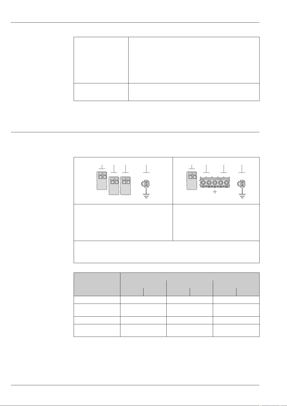
Remote version
In the case of the remote version, the sensor and transmitter are mounted separately from one
another and connected by a connecting cable. The sensor is connected via the connection housing
while the transmitter is connected via the connection compartment of the wall holder unit.
The way the transmitter wall holder is connected depends on the measuring device approval
and the version of the connecting cable used.
Connection is only possible via terminals:
• For approvals Ex n, Ex tb and cCSAus Div. 1
• If a reinforced connecting cable is used
The connection is via an M12 connector:
• For all other approvals
• If the standard connecting cable is used
Connection to the connection housing of the sensor is always via terminals.
A0019335
3 Terminals for connection compartment in the transmitter wall holder and the sensor connection housing
1 Terminals for connecting cable
2 Grounding via the cable strain relief
Terminal number Assignment Cable color
Connecting cable
1 Supply voltage Brown
2 Grounding White
3 RS485 (+) Yellow
4 RS485 (–) Green
Endress+Hauser 21
Page 22

Pin assignment, device plug PROFIBUS PA
1
2
4
3
1
2
4
3
Device plug for signal transmission (device side)
FOUNDATION Fieldbus
Device plug for signal transmission (device side)
Proline Prowirl C 200
Pin Assignment Coding Plug/socket
1 + PROFIBUS PA + A Plug
2 Grounding
A0019021
A0019021
3 - PROFIBUS PA –
4 Not assigned
Pin Assignment Coding Plug/socket
1 + Signal + A Plug
2 - Signal –
3 Not assigned
4 Grounding
Supply voltage Transmitter
An external power supply is required for each output.
Supply voltage for a compact version without a local display
Order code for "Output" Minimum
Option A: 4-20 mA HART ≥DC 12 V DC 35 V
Option B: 4-20 mA HART, pulse/
frequency/switch output
Option C: 4-20 mA HART, 4-20 mA ≥DC 12 V DC 30 V
Option D: 4-20 mA HART, pulse/
frequency/switch output, 4-20 mA current
3)
input
Option E : FOUNDATION Fieldbus, pulse/
frequency/switch output
Option G: PROFIBUS PA, pulse/frequency/
switch output
1) In event of external supply voltage of the power supply unit with load, the PROFIBUS DP/PA coupler or
FOUNDATION Fieldbus power conditioners
2) The minimum terminal voltage increases if local operation is used: see the following table
3) Voltage drop 2.2 to 3 V for 3.59 to 22 mA
1)
terminal voltage
≥DC 12 V DC 35 V
≥DC 12 V DC 35 V
≥DC 9 V DC 32 V
≥DC 9 V DC 32 V
2)
terminal voltage
Maximum
22 Endress+Hauser
Page 23

Proline Prowirl C 200
Increase in minimum terminal voltage
Local operation
Order code for "Display; Operation", option C:
Local operation SD02
Order code for "Display; Operation", option E:
Local operation SD03 with lighting
(backlighting not used)
Order code for "Display; Operation", option E:
Local operation SD03 with lighting
(backlighting used)
For information about the load see (→ 12)
Various power supply units can be ordered from Endress+Hauser: see "Accessories" section
(→ 66)
For information on the Ex connection values (→ 12)
Power consumption Transmitter
Order code for "Output" Maximum power consumption
Option A: 4-20 mA HART 770 mW
Option B: 4-20 mA HART, pulse/
frequency/switch output
Option C: 4-20 mA HART, 4-20 mA • Operation with output 1: 660 mW
Option D: 4-20 mA HART, pulse/
frequency/switch output, 4-20 mA current
input
Option E: FOUNDATION Fieldbus, pulse/
frequency/switch output
Option G: PROFIBUS PA, pulse/frequency/
switch output
Increase in minimum
terminal voltage
+ DC 1 V
+ DC 1 V
+ DC 3 V
• Operation with output 1: 770 mW
• Operation with output 1 and 2: 2 770 mW
• Operation with output 1 and 2: 1 320 mW
• Operation with output 1: 770 mW
• Operation with output 1 and 2: 2770 mW
• Operation with output 1 and input: 840 mW
• Operation with output 1, 2 and input: 2840 mW
• Operation with output 1: 512 mW
• Operation with output 1 and 2: 2 512 mW
• Operation with output 1: 512 mW
• Operation with output 1 and 2: 2 512 mW
For information on the Ex connection values (→ 12)
Current consumption Current output
For every 4-20 mA or 4-20 mA HART current output: 3.6 to 22.5 mA
If the option Defined value is selected in the Failure mode parameter (→ 11):
3.59 to 22.5 mA
Current input
3.59 to 22.5 mA
Internal current limiting: max. 26 mA
PROFIBUS PA
15 mA
FOUNDATION Fieldbus
15 mA
Endress+Hauser 23
Page 24

Proline Prowirl C 200
1
1
3
1
2 2
Power supply failure
• Totalizers stop at the last value measured.
• Configuration is retained in the device memory (HistoROM).
• Error messages (incl. total operated hours) are stored.
Electrical connection Connecting the transmitter
1 Cable entries for inputs/outputs
Remote version connection
Connecting cable
A0020740
4 Connecting cable connection
1 Wall holder with connection compartment (transmitter)
2 Connecting cable
3 Sensor connection housing
The way the transmitter wall holder is connected depends on the measuring device approval
and the version of the connecting cable used.
Connection is only possible via terminals:
• For approvals Ex n, Ex tb and cCSAus Div. 1
• If a reinforced connecting cable is used
The connection is via an M12 connector:
• For all other approvals
• If the standard connecting cable is used
Connection to the connection housing of the sensor is always via terminals.
24 Endress+Hauser
A0019727
Page 25

Proline Prowirl C 200
2
4
4...20 mA
5
631
+
-
7
+
-
2
4...20 mA
3
1
+
-
4
+
–
+
-
Connection examples
Current output 4-20 mA HART
A0015511
5 Connection example for 4-20 mA HART current output (passive)
1 Automation system with current input (e.g. PLC)
2 Active barrier for power supply (e.g. RN221N) (→ 29)
3 Cable shield, observe cable specifications (→ 29)
4 Resistor for HART communication (≥ 250 Ω): observe maximum load (→ 12)
5 Connection for HART operating devices (→ 58)
6 Analog display unit: observe maximum load (→ 12)
7 Transmitter
Current output 4-20 mA
6 Connection example for 4-20 mA current output (passive)
1 Automation system with current input (e.g. PLC)
2 Active barrier for power supply (e.g. RN221N) (→ 22)
3 Analog display unit: observe maximum load (→ 12)
4 Transmitter
A0015512
Endress+Hauser 25
Page 26

Pulse/frequency output
1
+
_
12345
2
+
–
+
–
3
1
+
_
+
_
2
+
_
3
7 Connection example for pulse/frequency output (passive)
1 Automation system with pulse/frequency input (e.g. PLC)
2 Power supply
3 Transmitter: observe input values (→ 9)
Switch output
Proline Prowirl C 200
A0016801
8 Connection example for switch output (passive)
1 Automation system with switch input (e.g. PLC)
2 Power supply
3 Transmitter: observe input values (→ 9)
A0016802
26 Endress+Hauser
Page 27

Proline Prowirl C 200
21 3
+
-
+
-
+
-
4
5
5
78
6
6
6
6
6
6
.
-
PROFIBUS-PA
A0019004
9 Connection example for PROFIBUS-PA
1 Control system (e.g. PLC)
2 Segment coupler PROFIBUS DP/PA
3 Cable shield
4 T-box
5 Measuring device
6 Local grounding
7 Bus terminator
8 Potential matching line
Endress+Hauser 27
Page 28

FOUNDATION Fieldbus
21 3
+
-
+
-
+
-
4
5
5
78
6
6
6
6
6
6
.
-
1
+
-
3
+
-
2
Proline Prowirl C 200
10 Connection example for FOUNDATION Fieldbus
1 Control system (e.g. PLC)
2 Power Conditioner (FOUNDATION Fieldbus)
3 Cable shield
4 T-box
5 Measuring device
6 Local grounding
7 Bus terminator
8 Potential matching line
Current input
11 Connection example for 4-20 mA current input
1 Power supply
2 External measuring device (for reading in pressure or temperature, for instance)
3 Transmitter: observe input values (→ 9)
A0019004
A0020741
28 Endress+Hauser
Page 29

Proline Prowirl C 200
3
4...20 mA
5
1
+
-
3
6
+
–
+
+
–
+
–
+
–
+
–
–
2
4
4
7
+
-
HART input
A0016029
12 Connection example for HART input with a common negative
1 Automation system with HART output (e.g. PLC)
2 Resistor for HART communication (≥ 250 Ω): observe maximum load (→ 12)
3 Active barrier for power supply (e.g. RN221N) (→ 22)
4 Cable shield, observe cable specifications (→ 29)
5 Analog display unit: observe maximum load (→ 12)
6 Pressure transmitter (e.g. Cerabar M, Cerabar S): see requirements (→ 8)
7 Transmitter
Potential equalization Requirements
Please consider the following to ensure correct measurement:
• Same electrical potential for the fluid and sensor
• Remote version: same electrical potential for the sensor and transmitter
• Company-internal grounding concepts
• Pipe material and grounding
For devices intended for use in hazardous locations, please observe the guidelines in the Ex
documentation (XA).
Terminals
• For device version without integrated overvoltage protection: plug-in spring terminals for wire
cross-sections 0.5 to 2.5 mm2 (20 to 14 AWG)
• For device version with integrated overvoltage protection: screw terminals for wire cross-sections
0.2 to 2.5 mm2 (24 to 14 AWG)
Cable entries
• Cable gland (not for Ex d): M20 × 1.5 with cable 6 to 12 mm (0.24 to 0.47 in)
• Thread for cable entry:
– For non-Ex and Ex: NPT ½"
– For non-Ex and Ex (not for CSA Ex d/XP): G ½"
– For Ex d: M20 × 1.5
Cable specification Permitted temperature range
• –40 °C (–40 °F) to +80 °C (+176 °F)
• Minimum requirement: cable temperature range ≥ ambient temperature +20 K
Signal cable
Current output
For 4-20 mA HART: Shielded cable recommended. Observe grounding concept of the plant.
Pulse/frequency/switch output
Standard installation cable is sufficient.
Endress+Hauser 29
Page 30

Proline Prowirl C 200
Current input
Standard installation cable is sufficient.
FOUNDATION Fieldbus
Twisted, shielded two-wire cable.
For further information on planning and installing FOUNDATION Fieldbus networks see:
• Operating Instructions for "FOUNDATION Fieldbus Overview" (BA00013S)
• FOUNDATION Fieldbus Guideline
• IEC 61158-2 (MBP)
PROFIBUS PA
Twisted, shielded two-wire cable. Cable type A is recommended.
For further information on planning and installing PROFIBUS PA networks see:
• Operating Instructions "PROFIBUS DP/PA: Guidelines for planning and commissioning"
(BA00034S)
• PNO Directive 2.092 "PROFIBUS PA User and Installation Guideline"
• IEC 61158-2 (MBP)
Connecting cable for remote version
Connecting cable (standard)
Standard cable
Flame resistance According to DIN EN 60332-1-2
Oil-resistance According to DIN EN 60811-2-1
Shielding Galvanized copper-braid, opt. density approx. 85%
Cable length 5 m (16 ft), 10 m (32 ft), 20 m (65 ft), 30 m (98 ft)
Operating temperature When mounted in a fixed position: –50 to +105 °C (–58 to +221 °F); when cable
4 × 2 × 0.34 mm2 (22 AWG) PVC cable with common shield (4 pairs, pairstranded)
can move freely: –25 to +105 °C (–13 to +221 °F)
Connecting cable (reinforced)
Cable, reinforced
Flame resistance According to DIN EN 60332-1-2
Oil-resistance According to DIN EN 60811-2-1
Shielding Galvanized copper-braid, opt. density approx. 85%
Strain relief and
reinforcement
Cable length 5 m (16 ft), 10 m (32 ft), 20 m (65 ft), 30 m (98 ft)
Operating temperature When mounted in a fixed position: –50 to +105 °C (–58 to +221 °F); when cable
4 × 2 × 0.34 mm2 (22 AWG) PVC cable with common shield (4 pairs, pairstranded) and additional steel-wire braided sheath
Steel-wire braid, galvanized
can move freely: –25 to +105 °C (–13 to +221 °F)
Overvoltage protection
The device can be ordered with integrated overvoltage protection for diverse approvals:
Order code for "Accessory mounted", option NA "Overvoltage protection"
Input voltage range Values correspond to supply voltage specifications (→ 22)
Resistance per channel 2 ⋅0.5 Ω max
DC sparkover voltage 400 to 700 V
Trip surge voltage <800 V
Capacitance at 1 MHz <1.5 pF
1)
30 Endress+Hauser
Page 31

Proline Prowirl C 200
Re
min
Re
max
Re
Re
max
A2
A1
-A1
-A2
R1
R2
Nominal discharge current
(8/20 μs)
Temperature range –40 to +85 °C (–40 to +185 °F)
1) The voltage is reduced by the amount of the internal resistance I
Depending on the temperature class, restrictions apply to the ambient temperature for device
versions with overvoltage protection (→ 38)
Performance characteristics
Reference operating conditions
Maximum measured error Base accuracy
• Error limits following ISO/DIN 11631
• +20 to +30 °C (+68 to +86 °F)
• 2 to 4 bar (29 to 58 psi)
• Calibration system traceable to national standards
• Calibration with the process connection corresponding to the particular standard
To obtain measured errors, use the Applicator sizing tool (→ 65)
o.r. = of reading, Re = Reynolds number
Volume flow
The measured error for the volume flow is as follows depending on the Reynolds number and the
compressibility of the medium under measurement:
10 kA
min
⋅ R
i
Deviation of volume flow value (absolute) from the reading
Re range Measured value deviation Standard Standard
R1 to R2 A2 < 10 % < 10 %
R2 to Re
max
1) Accuracy specifications valid up to 75 m/s (246 ft/s)
Medium type Incompressible Compressible
A1 < 0.75 % < 1.0 %
Endress+Hauser 31
A0019703
1)
Page 32

Proline Prowirl C 200
Reynolds numbers
R1 5 000
R2 20 000
Incompressible Compressible
Standard Standard
Temperature
• Saturated steam and liquids at room temperature if T > 100 °C (212 °F) applies: < 1 °C (1.8 °F)
• Gas: < 1 % o.r. [K]
Rise time 50 % (stirred under water, following IEC 60751): 8 s
Mass flow (saturated steam)
• Flow velocities 20 to 50 m/s (66 to 164 ft/s), T > 150 °C (302 °F) or (423 K)
– Re > 20 000: < 1.7 % o.r.
– Re between 5 000 to 20 000: < 10 % o.r.
• Flow velocities 10 to 70 m/s (33 to 210 ft/s), T > 140 °C (284 °F) or (413 K)
– Re > 20 000: < 2 % o.r.
– Re between 5 000 to 20 000: < 10 % o.r.
The use of a Cerabar S is required for the measured errors listed in the following section. The
measured error used to calculate the error in the measured pressure is 0.15%.
Mass flow of superheated steam and gas (single gas, gas mixture, air: NEL40; natural gas: ISO
12213-2 contains AGA8-DC92, AGA NX-19, ISO 12213-3 contains SGERG-88 and AGA8 Gross
Method 1)
• Re > 20 000 and process pressure < 40 bar abs. (580 psi abs.): 1.7 % o.r.
• Re between 5 000 to 20 000 and process pressure < 40 bar abs. (580 psi abs.): 10 % o.r.
• Re > 20 000 and process pressure < 120 bar abs. (1 740 psi abs.): 2.6 % o.r.
• Re between 5 000 to 20 000 and process pressure < 120 bar abs. (1 740 psi abs.): 10 % o.r.
abs. = absolute
Mass flow (water)
• Re 20 000: < 0.85 % o.r.
• Re between 5 000 to 20 000: < 10 % o.r.
Mass flow (user-defined liquids)
To specify the system accuracy, Endress+Hauser requires information about the type of liquid and its
operating temperature or information in table form about the dependency between the liquid
density and the temperature.
Example
• Acetone is to be measured at fluid temperatures between +70 to +90 °C (+158 to +194 °F).
• For this purpose the Reference temperature parameter (7703) (here 80 °C (176 °F)), Reference
density parameter (7700) (here 720.00 kg/m3) and Linear expansion coefficient parameter
(7621) (here 18.0298 × 10⁻⁴ 1/°C) must be entered in the transmitter.
• The overall system uncertainty, which is smaller than 0.9 % for the example above, is comprised of
the following uncertainties of measurement: uncertainty of volume flow measurement,
uncertainty of temperature measurement, uncertainty of the density-temperature correlation used
(incl. the resulting uncertainty of density).
Mass flow (other media)
Depends on the selected fluid and the pressure value, which is specified in the parameters. Individual
error analysis must be performed.
Accuracy of outputs
o.r. = of reading
Current output
Accuracy ±10 µA
Pulse/frequency output
Accuracy Max. ±100 ppm o.r.
32 Endress+Hauser
Page 33

Proline Prowirl C 200
Repeatability
Response time
Influence of ambient temperature
o.r. = of reading
±0.2 % o.r.
If all the configurable functions for filter times (flow damping, display damping, current output time
constant, frequency output time constant, status output time constant) are set to 0, in the event of
vortex frequencies of 10 Hz and higher a response time of max(Tν,100 ms) can be expected.
In the event of measuring frequencies < 10 Hz, the response time is > 100 ms and can be up to 10 s.
Tν is the average vortex period duration of the flowing fluid.
o.r. = of reading
Current output
Additional error, in relation to the span of 16 mA:
Temperature coefficient at
zero point (4 mA)
Temperature coefficient
with span (20 mA)
0.02 %/10 K
0.05 %/10 K
Pulse/frequency output
Temperature coefficient Max. ±100 ppm o.r.
Mounting location
Orientation
Installation
A0015543
The direction of the arrow on the sensor nameplate helps you to install the sensor according to the
flow direction (direction of medium flow through the piping).
Vortex meters require a fully developed flow profile as a prerequisite for correct volume flow
measurement. Therefore, please note the following:
Orientation Compact version Remote version
A Vertical orientation
1)
A0015545
B Horizontal orientation, transmitter head up
A0015589
2) 3)
Endress+Hauser 33
Page 34

Proline Prowirl C 200
A
L
Orientation Compact version Remote version
C Horizontal orientation, transmitter head down
A0015590
D Horizontal orientation, transmitter head at side
A0015592
1) In the case of liquids, there should be upward flow in vertical pipes to avoid partial pipe filling (Fig. A).
Disruption in flow measurement! In the case of vertical orientation and downward flowing liquid, the pipe
always needs to be completely filled to ensure correct liquid flow measurement.
2) Danger of electronics overheating! If the fluid temperature is ≥ 200 °C (392 °F) orientation B is not
permitted for the wafer version (Prowirl D) with nominal diameters DN 100 (4") and DN 150 (6").
3) In the case of hot media (e.g. steam or fluid temperature (TM) ≥ 200 °C (392 °F): orientation C or D
4) In the case of very cold media (e.g. liquid nitrogen): orientation B or D
5) For "wet steam detection/measurement" option: orientation C
Minimum spacing and cable length
4) 5)
4)
Inlet and outlet runs
A0019211
A Minimum spacing in all directions
L Required cable length
The following dimensions must be observed to guarantee problem-free access to the device for
service purposes:
• A =100 mm (3.94 in)
• L = L + 150 mm (5.91 in)
Rotating the electronics housing and the display
The electronics housing can be rotated continuously by 360 °° on the housing support. The display
unit can be rotated in 45 ° stages. This means you can read the display comfortably from all
directions.
To attain the specified level of accuracy of the measuring device, the inlet and outlet runs mentioned
below must be maintained at the very minimum.
34 Endress+Hauser
Page 35

Proline Prowirl C 200
15 × DN
5 × DN
1
3
25 × DN
5 × DN
40 × DN
5 × DN
4
2
20 × DN
5 × DN
5
20 × DN
5 × DN
6
17 × DN + 8 × h
5 × DN
h
7
50 × DN
5 × DN
9
40 × DN
5 × DN
8
5 × DN
DN 25 (1"):≤
DN 40 (1½"):≥
PT
TT
3...5 x DN
4...8 x DN
A0019189
13 Minimum inlet and outlet runs with various flow obstructions
h Difference in expansion
1 Reduction by one nominal diameter size
2 Single elbow (90° elbow)
3 Double elbow (2 × 90° elbows, opposite)
4 Double elbow 3D (2 × 90° elbows, opposite, not on one plane)
5 T-piece
6 Expansion
7 Control valve
8 Two measuring devices in a row where DN ≤ 25 (1"): directly flange on flange
9 Two measuring devices in a row where DN ≥ 40 (1½"): for spacing, see graphic
Length of connecting cable
Outlet runs when installing external devices
If installing an external device, observe the specified distance.
PT Pressure transmitter
TT Temperature transmitter
To ensure correct measuring results when using the remote version,
• observe the maximum permitted cable length L
max
.
• The value for the cable length must be calculated if the cable cross-section differs from the
specification.
For detailed information about calculating the length of the connecting cable, refer to the
Operating Instructions for the device on the CD-ROM provided
A0019205
Endress+Hauser 35
Page 36

Proline Prowirl C 200
80 (3.15)
80 (3.15)
19 (0.6)
! 8.6 (0.39)
M 8
! 20…70
(! 0.79 to 2.75)
1
4 x
SW 13
Installing the wall-mount housing
Wall mounting
A0019864
14 Engineering unit mm (in)
Post mounting
15 Engineering unit mm (in)
1 Post retainer kit for post mounting
36 Endress+Hauser
A0019862
Page 37

Proline Prowirl C 200
Q
1
2
3
Special mounting instructions
Inspection kit
The inspection kit contains the necessary parts for the annual visual inspection of the primary
measurement element (bluff body) in accordance with ERCB Dir. 017.
Consists of:
• 2 inspection centering sleeves
• 8 screws
• 2 inspection seals
• 2 inspection covers
The centering sleeve supports the user by centering the calipers in the inspection ports. This makes it
easier to measure the distance from the sealing surface to the bluff body. In addition, the kit also
contains screws, seals and covers for the inspection ports.
An inspection kit can be ordered separately (see the "Accessories" section (→ 64)).
Installation for delta heat measurements
Order code for "Sensor version", option 3 "Mass flow (integrated temperature measurement)"
The second temperature measurement is taken using a separate temperature sensor. The measuring
device reads in this value via a communication interface.
• In the case of saturated steam delta heat measurements, the Prowirl 200 must be installed on the
steam side.
• In the case of water delta heat measurements, the Prowirl 200 can be installed on the cold or
warm side.
A0019209
16 Layout for delta heat measurement of saturated steam and water
1 Prowirl
2 Temperature sensor
3 Heat exchanger
Q Heat flow
Weather protection cover
Observe the following minimum head clearance: 222 mm (8.74 in)
For information the weather protection cover, see (→ 63)
Endress+Hauser 37
Page 38

Environment
Proline Prowirl C 200
Ambient temperature range
Compact version
Measuring device Non-Ex: –40 to +80 °C (–40 to +176 °F)
Ex i: –40 to +70 °C (–40 to +158 °F)
EEx d/XP version: –40 to +60 °C (–40 to +140 °F)
ATEX II1/2G Ex d, Ex ia: –40 to +60 °C (–40 to +140 °F)
Local display –20 to +60 °C (–4 to +140 °F)
1) Additionally available as order code for "Test, certificate", option JN "Transmitter ambient temperature –50
°C (–58 °F)".
1)
1)
1)
1)
Remote version
Transmitter Non-Ex: –40 to +80 °C (–40 to +176 °F)
Ex i: –40 to +80 °C (–40 to +176 °F)
Ex d: –40 to +60 °C (–40 to +140 °F)
ATEX II1/2G Ex d, Ex ia: –40 to +60 °C (–40 to +140 °F)
Sensor Non-Ex: –40 to +85 °C (–40 to +185 °F)
Ex i: –40 to +85 °C (–40 to +185 °F)
Ex d: –40 to +85 °C (–40 to +185 °F)
ATEX II1/2G Ex d, Ex ia: –40 to +85 °C (–40 to +185 °F)
Local display –20 to +60 °C (–4 to +140 °F)
1)
1)
1)
1)
1)
1)
1)
1)
1) Additionally available as order code for "Test, certificate", option JN "Transmitter ambient temperature –50
°C (–58 °F)".
If operating outdoors:
‣
Avoid direct sunlight, particularly in warm climatic regions.
Weather protection covers can be ordered from Endress+Hauser: see "Accessories" section
(→ 63)
Temperature tables
Tm = fluid temperature, Ta = ambient temperature
The following interdependencies between the permitted ambient and fluid temperatures apply when
operating the device in hazardous areas:
Compact version
Order code for "Sensor version", option 4 "Volume flow Alloy 718"; option 6 "Mass flow Alloy 718"
Order code for "Output", option A "4-20mA HART"
Order code for "Approval", all options
CSAUS IS, CCSAUS XP, CCSAUS NI
C
SI units
Version with max. Tm = 280 °C
1)
T
a
[ºC]
40 80 95 130 195 280 –
60 – 95 130 195 280 –
T6
[85 °C]
T5
[100 °C]
T4
[135 °C]
T3
[200 °C]
T2
[300 °C]
T1
[450 °C]
38 Endress+Hauser
Page 39

Proline Prowirl C 200
Version with max. Tm = 280 °C
1)
T
a
[ºC]
T6
[85 °C]
T5
[100 °C]
T4
[135 °C]
T3
[200 °C]
T2
[300 °C]
T1
[450 °C]
65 – – 130 195 280 –
70 – – 130 – – –
1) The following applies for installations with overvoltage protection in conjunction with temperature class
T5, T6 and approval options BA, BB, BD, BH, BJ, B2, IA, IB, ID, IH, IJ, I4, C2: Ta = Ta - 2 °C
US units
Version with max. Tm = 536 °F
1)
T
a
[ºF]
104 176 203 266 383 536 –
140 – 203 266 383 536 –
149 – – 266 383 536 –
158 – – 266 – – –
T6
[185 °F]
T5
[212 °F]
T4
[275 °F]
T3
[392 °F]
T2
[572 °F]
T1
[842 °F]
1) The following applies for installations with overvoltage protection in conjunction with temperature class
T5, T6 and approval options BA, BB, BD, BH, BJ, B2, IA, IB, ID, IH, IJ, I4, C2: Ta = Ta - 35.6 °F
Order code for "Output", option B "4-20mA HART, pulse/frequency/switch output"
Order code for "Approval", options BA, BB, BD, BH, BJ, B2, IA, IB, ID, IH, IJ, I4, C2
CSAUS IS
C
SI units
Version with max. Tm = 280 °C
1)
T
a
[ºC]
2)
35
3)
50
60 – – 130 195 280 –
65 – – 130 195 280
70 – – 130 195
1) The following applies for installations with overvoltage protection in conjunction with temperature class
T5, T6 and approval options BA, BB, BD, BH, BJ, B2, IA, IB, ID, IH, IJ, I4, C2: Ta = Ta - 2 °C
2) Ta = 40 °C for pulse/frequency/switch output Pi = 0.85 W
3) Ta = 55 °C for pulse/frequency/switch output Pi = 0.85 W
4) Ta = 65 °C for pulse/frequency/switch output Pi = 0.7 W
5) Ta = 70 °C for pulse/frequency/switch output Pi = 0.7 W
T6
[85 °C]
T5
[100 °C]
T4
[135 °C]
T3
[200 °C]
T2
[300 °C]
80 95 130 195 280 –
– 95 130 195 280 –
4)
5)
280
5)
T1
[450 °C]
–
–
US units
Version with max. Tm = 536 °F
1)
T
[ºF]
95
122
a
2)
3)
T6
[185 °F]
T5
[212 °F]
T4
[275 °F]
T3
[392 °F]
T2
[572 °F]
176 203 266 383 536 –
– 203 266 383 536 –
T1
[842 °F]
140 – – 266 383 536 –
Endress+Hauser 39
Page 40

Proline Prowirl C 200
Version with max. Tm = 536 °F
1)
T
a
[ºF]
149 – – 266 383 536
158 – – 266 383
1) The following applies for installations with overvoltage protection in conjunction with temperature class
T5, T6 and approval options BA, BB, BD, BH, BJ, B2, IA, IB, ID, IH, IJ, I4, C2: Ta = Ta - 35.6 °F
2) Ta = 104 °F for pulse/frequency/switch output Pi = 0.85 W
3) Ta = 131 °F for pulse/frequency/switch output Pi = 0.85 W
4) Ta = 149 °F for pulse/frequency/switch output Pi = 0.7 W
5) Ta = 158 °F for pulse/frequency/switch output Pi = 0.7 W
Order code for "Approval", options BC, BG, BK, B3, IC, IG, IK, I5, C3
CSAUS XP
C
SI units
Version with max. Tm = 280 °C
T
a
[ºC]
40 80 95 130 195 280 –
55 – 95 130 195 280 –
65 – – 130 195 280
70 – – 130 195
[185 °F]
T6
[85 °C]
T6
[212 °F]
T5
[100 °C]
T5
T4
[275 °F]
T4
[135 °C]
T3
[392 °F]
T3
[200 °C]
2)
T2
[572 °F]
4)
5)
536
5)
T2
[300 °C]
1)
2)
280
T1
[842 °F]
–
–
T1
[450 °C]
–
–
1) Ta = 65 °C for pulse/frequency/switch output Pi = 0.7 W
2) Ta = 70 °C for pulse/frequency/switch output Pi = 0.7 W
US units
Version with max. Tm = 536 °F
T
[ºF]
a
T6
[185 °F]
T5
[212 °F]
T4
[275 °F]
T3
[392 °F]
T2
[572 °F]
104 176 203 266 383 536 –
131 – 203 266 383 536 –
536
1)
2)
149 – – 266 383 536
158 – – 266 383
2)
1) Ta = 149 °F for pulse/frequency/switch output Pi = 0.7 W
2) Ta = 158 °F for pulse/frequency/switch output Pi = 0.7 W
Order code for "Output", option C "4-20mA HART, 4-20mA"
Order code for "Approval", all options
CSAUS IS, CCSAUS XP, CCSAUS NI
C
SI units
Version with max. Tm = 280 °C
1)
T
a
[ºC]
40 80 95 130 195 280 –
55 – 95 130 195 280 –
60 – – 130 195 280 –
T6
[85 °C]
T5
[100 °C]
T4
[135 °C]
T3
[200 °C]
T2
[300 °C]
T1
[842 °F]
–
–
T1
[450 °C]
40 Endress+Hauser
Page 41

Proline Prowirl C 200
Version with max. Tm = 280 °C
1)
T
a
[ºC]
65 – – 130 195 280
T6
[85 °C]
T5
[100 °C]
T4
[135 °C]
T3
[200 °C]
T2
[300 °C]
2)
T1
[450 °C]
–
70 – – 130 – – –
1) The following applies for installations with overvoltage protection in conjunction with temperature class
T5, T6 and approval options BA, BB, BD, BH, BJ, B2, IA, IB, ID, IH, IJ, I4, C2: Ta = Ta - 2 °C
2) Ta = 65 °C for pulse/frequency/switch output Pi = 0 W
US units
Version with max. Tm = 536 °F
1)
T
a
[ºF]
104 176 203 266 383 536 –
131 – 203 266 383 536 –
140 – – 266 383 536 –
149 – – 266 383 536
158 – – 266 – – –
T6
[185 °F]
T5
[212 °F]
T4
[275 °F]
T3
[392 °F]
T2
[572 °F]
2)
T1
[842 °F]
–
1) The following applies for installations with overvoltage protection in conjunction with temperature class
T5, T6 and approval options BA, BB, BD, BH, BJ, B2, IA, IB, ID, IH, IJ, I4, C2: Ta = Ta - 35.6 °F
2) Ta = 149 °F for pulse/frequency/switch output Pi = 0 W
Order code for "Output", option D "4-20 mA HART, PFS output; 4-20 mA input"
Order code for "Approval", all options
CSAUS IS, CCSAUS XP, CCSAUS NI
C
SI units
Version with max. Tm = 280 °C
1)
T
a
[ºC]
T6
[85 °C]
T5
[100 °C]
T4
[135 °C]
T3
[200 °C]
T2
[300 °C]
T1
[450 °C]
35 80 95 130 195 280 –
50 – 95 130 195 280 –
55 – – – 195 280 –
60 – – – 195 – –
1) The following applies for installations with overvoltage protection in conjunction with temperature class
T5, T6 and approval options BA, BB, BD, BH, BJ, B2, IA, IB, ID, IH, IJ, I4, C2: Ta = Ta - 2 °C
US units
Version with max. Tm = 536 °F
1)
T
a
[ºF]
95 176 203 266 383 536 –
122 – 203 266 383 536 –
131 – – – 383 536 –
140 – – – 383 – –
T6
[185 °F]
T5
[212 °F]
T4
[275 °F]
T3
[392 °F]
T2
[572 °F]
T1
[842 °F]
1) The following applies for installations with overvoltage protection in conjunction with temperature class
T5, T6 and approval options BA, BB, BD, BH, BJ, B2, IA, IB, ID, IH, IJ, I4, C2: Ta = Ta - 35.6 °F
Endress+Hauser 41
Page 42

Proline Prowirl C 200
Order code for "Output", option E "FOUNDATION Fieldbus, pulse/frequency/switch output" and
option G "PROFIBUS PA, pulse/frequency/switch output"
Order code for "Approval", all options
CSAUS IS, CCSAUS XP, CCSAUS NI
C
SI units
Version with max. Tm = 280 °C
1)
T
a
[ºC]
40 80 95 130 195 280 –
2)
50
60 – – 130 195 280 –
65 – – 130 195 280
70 – – 130 195
1) The following applies for installations with overvoltage protection in conjunction with temperature class
T5, T6 and approval options BA, BB, BD, BH, BJ, B2, IA, IB, ID, IH, IJ, I4, C2: Ta = Ta - 2 °C
2) Ta = 60 °C for pulse/frequency/switch output Pi = 0 W
3) Ta = 65 °C for pulse/frequency/switch output Pi = 0 W
4) Ta = 70 °C for pulse/frequency/switch output Pi = 0 W
T6
[85 °C]
T5
[100 °C]
T4
[135 °C]
T3
[200 °C]
T2
[300 °C]
– 95 130 195 280 –
3)
4)
280
4)
T1
[450 °C]
–
–
US units
Version with max. Tm = 536 °F
1)
T
[°F]
a
T6
[185 °F]
T5
[212 °F]
T4
[275 °F]
T3
[392 °F]
T2
[572 °F]
T1
[842 °F]
104 176 203 266 383 536 –
2)
122
– 203 266 383 536 –
140 – – 266 383 536 –
536
3)
4)
–
–
149 – – 266 383 536
158 – – 266 383
4)
1) The following applies for installations with overvoltage protection in conjunction with temperature class
T5, T6 and approval options BA, BB, BD, BH, BJ, B2, IA, IB, ID, IH, IJ, I4, C2: Ta = Ta - 35.6 °F
2) Ta = 140 °F for pulse/frequency/switch output Pi = 0 W
3) Ta = 149 °F for pulse/frequency/switch output Pi = 0 W
4) Ta = 158 °F for pulse/frequency/switch output Pi = 0 W
Remote version
Transmitter
Order code for "Housing", option J "GT20 two-chamber, remote G314, aluminum coated"; option K
"GT20 two-chamber, remote G315, 316L"
SI units
Order code for "Output", option Order code for
"Approval", option
A All 40 60 75
B BA, BB, BD, BH, BJ, B2, IA,
IB, ID, IH, IJ, I4, C2
BC, BG, BK, B3, IC, IG, IK,
I5, C3
C All 40 55 70
T6
[85 °C]
1)
35
T5
[100 °C]T4[135 °C]
2)
50
40 55 70
70
3)
3)
4)
42 Endress+Hauser
Page 43

Proline Prowirl C 200
Order code for "Output", option Order code for
"Approval", option
D All 35
E
All 40 55 70
T6
[85 °C]
5)
T5
[100 °C]T4[135 °C]
5)
50
65
4)
G
1) Ta = 40 °C for pulse/frequency/switch output Pi = 0.85 W
2) Ta = 60 °C for pulse/frequency/switch output Pi = 0.85 W
3) Ta = 75 °C for pulse/frequency/switch output Pi = 0.85 W
4) Ta = 75 °C for pulse/frequency/switch output Pi = 0 W
5) The following applies for installations with overvoltage protection in conjunction with temperature class
T5, T6 and approval options BA, BB, BD, BH, BJ, B2, IA, IB, ID, IH, IJ, I4, C2: Ta = Ta - 2 °C
US units
Order code for "Output", option Order code for
"Approval", option
A All 104 140 167
B BA, BB, BD, BH, BJ, B2, IA,
IB, ID, IH, IJ, I4, C2
BC, BG, BK, B3, IC, IG, IK,
I5, C3
C All 104 131 158
D All 95
E
All 104 131 158
G
T6
[185 °F]T5[212 °F]T4[275 °F]
1)
95
104 131 158
5)
122
122
2)
5)
158
149
3)
3)
4)
4)
1) Ta = 104 °F for pulse/frequency/switch output Pi = 0.85 W
2) Ta = 140 °F for pulse/frequency/switch output Pi = 0.85 W
3) Ta = 167 °F for pulse/frequency/switch output Pi = 0.85 W
4) Ta = 167 °F for pulse/frequency/switch output Pi = 0 W
5) The following applies for installations with overvoltage protection in conjunction with temperature class
T5, T6 and approval options BA, BB, BD, BH, BJ, B2, IA, IB, ID, IH, IJ, I4, C2: Ta = Ta - 35.6 °F
Sensor
Order code for "Sensor version", option 4 "Volume flow Alloy 718"; option 6 "Mass flow Alloy 718"
SI units
Version with max. Tm = 280 °C
T
[ºC]
a
T6
[85 °C]
T5
[100 °C]
T4
[135 °C]
T3
[200 °C]
T2
[300 °C]
T1
[450 °C]
55 80 95 130 195 280 –
70 – 95 130 195 280 –
85 – – 130 195 280 –
US units
Version with max. Tm = 536 °F
T
a
[°F]
104 176 203 266 383 536 –
122 – 203 266 383 536 –
149 – – 266 383 536 –
T6
[185 °F]
T5
[212 °F]
T4
[275 °F]
T3
[392 °F]
T2
[572 °F]
T1
[842 °F]
Endress+Hauser 43
Page 44

Proline Prowirl C 200
Storage temperature
Climate class
Degree of protection
Vibration resistance
Electromagnetic compatibility (EMC)
All components apart from the display modules:
–50 to +80 °C (–58 to +176 °F)
Display modules:
–40 to +80 °C (–40 to +176 °F)
DIN EN 60068-2-38 (test Z/AD)
Transmitter
• As standard: IP66/67, type 4X enclosure
• When housing is open: IP20, type 1 enclosure
• Display module: IP20, type 1 enclosure
Sensor
IP66/67, type 4X enclosure
Device plug
IP67, only in screwed situation
• For compact/remote version made of coated aluminum and remote version made of stainless steel:
Acceleration up to 2g (if gain set to factory setting), 10 to 500 Hz, following IEC 60068-2-6
• For the compact version made of stainless steel:
Acceleration up to 1g (if gain set to factory setting), 10 to 500 Hz, following IEC 60068-2-6
As per IEC/EN 61326 and NAMUR Recommendation 21 (NE 21)
For details refer to the Declaration of Conformity.
Medium temperature range
Pressure-temperature ratings
Process
DSC sensor
Order code for "Sensor version":
• Option 4 "Volume flow, Alloy 718":
–40 to +400 °C (–40 to +752 °F)
• Option 6 "Mass flow, Alloy 718":
–40 to +400 °C (–40 to +752 °F)
Seals
• –200 to +400 °C (–328 to +752 °F) for graphite (standard)
• –15 to +175 °C (+5 to +347 °F) for Viton
• –20 to +275 °C (–4 to +527 °F) for Kalrez
• –200 to +260 °C (–328 to +500 °F) for Gylon
The following pressure-temperature ratings refer to the entire device and not just the process
connection.
The pressure-temperature rating for the specific measuring device is programmed into the software.
If values exceed the curve range a warning is displayed. Depending on the system configuration and
sensor version, the pressure and temperature are determined by entering, reading in or calculating
values.
2)
2) Capacitance sensor
44 Endress+Hauser
Page 45

Proline Prowirl C 200
600 [°F]7005004003002001000
[°C]
400300200100
0
-60
800
60
80
100
120
140
160
180
[bar][psi]
1200
1600
2000
2400
Cl.900
Cl.600
1
Process connection: flange to ASME B16.5 ed. 2009, Group 1.1 materials
17 Process connection material: carbon steel, multiple certifications, SA-105, SA-350 LF2 (1)
NOTICE
If the device is used for a prolonged period at a temperature of over 375 °C, it is the
responsibility of the owner-operator to perform additional tests. These can include:
Dimensional tests to monitor deformation caused by corrosion or creepage.
‣
A0020882-EN
Pressure loss
Thermal insulation
For a precise calculation, use the Applicator(→ 65).
For optimum temperature measurement and mass calculation, heat transfer at the sensor must be
avoided for some fluids. This can be ensured by installing thermal insulation. A wide range of
materials can be used for the required insulation.
This applies for:
• Compact version
• Remote sensor version
The maximum insulation height permitted is illustrated in the diagram:
A0019212
1 Maximum insulation height
When insulating, ensure that a sufficiently large area of the housing support remains exposed.
‣
The uncovered part serves as a radiator and protects the electronics from overheating and excessive
cooling.
Vibrations
Design, dimensions Compact version
Endress+Hauser 45
The correct operation of the measuring system is not affected by plant vibrations up to 1 g,
10 to 500 Hz. Therefore no special measures are needed to secure the sensors.
Mechanical construction
Order code for "Housing", option C "GT20, two-chamber, aluminum coated"
Page 46

Flanged version
D
E
A
G
B
C
F
L
1
Proline Prowirl C 200
A0020234
1 Optional inspection ports: order code for "Sensor option", option CR "ERCB Dir. 017 inspection ports"
Dimensions in SI units
DN A B
1)
C D
[mm] [mm] [mm] [mm] [mm] [mm] [mm] [mm] [mm]
50 162 102 60 165 75 90 310
80 162 102 60 165 75 90 321
100 162 102 60 165 75 90 331
150 162 102 60 165 75 90 352
1) For version without local display: values - 7 mm
2) For version with overvoltage protection: values + 8 mm
3) For version without local display: values - 10 mm
4) dependent on respective process connection
2)
E F
2)
3)
G
L
4)
4)
4)
4)
Dimensions in US units
DN A B
1)
C D
[in] [in] [in] [in] [in] [in] [in] [in] [in]
2 6.38 4.02 2.36 6.50 2.95 3.54 12.4
3 6.38 4.02 2.36 6.50 2.95 3.54 12.64
4 6.38 4.02 2.36 6.50 2.95 3.54 13.03
6 6.38 4.02 2.36 6.50 2.95 3.54 13.86
2)
E F
2)
3)
G
L
4)
4)
4)
4)
1) For version without local display: values - 0.28 in
2) For version with overvoltage protection: values + 0.31 in
3) For version without local display: values - 0.39 in
4) dependent on respective process connection
Butt-weld version
Order code for "Process connection", option CAC "ASME Cl. 600/Sch.80 butt-weld"; option CAD "ASME
Cl. 900/Sch.160 butt-weld";
46 Endress+Hauser
Page 47

Proline Prowirl C 200
D
E
A
G
H
B
C
F
L
±2.5
( )±0.10
K
M
1
di
2
A0020317
18 Engineering unit mm (in)
1 Groove type as per ASME B31.3
2 Inspection ports
Dimensions in SI units
Cl. 600/Sch. 80: SA-106 Gr. B, SA-333 Gr. 6 (order code for "Process connection", option CAC)
DN A B
1)
C D
[mm] [mm] [mm] [mm] [mm] [mm] [mm] [mm] [mm] [mm] [mm] [mm] [mm]
50 162 102 60 165 75 90 310 354 288 60 172 49.3
80 162 102 60 165 75 90 321 378 325 88 200 73.7
100 162 102 60 165 75 90 331 402 394 114 226 97.1
150 162 102 60 165 75 90 352 450 566 168 280 146.3
1) For version without local display: values - 7 mm
2) For version with overvoltage protection: values + 8 mm
3) For version without local display: values - 10 mm
Cl. 900/Sch. 160: SA-106 Gr. B, SA-333 Gr. 6 (order code for "Process connection", option CAD)
DN A B
1)
C D
[mm] [mm] [mm] [mm] [mm] [mm] [mm] [mm] [mm] [mm] [mm] [mm] [mm]
50 162 102 60 165 75 90 310 354 288 60 172 42.9
80 162 102 60 165 75 90 321 378 325 88 200 66.7
100 162 102 60 165 75 90 331 402 394 114 226 87.3
150 162 102 60 165 75 90 352 450 566 168 280 131.7
2)
2)
E F G
E F G
3)
3)
H
3)
H
L K M di
3)
L K M di
1) For version without local display: values - 7 mm
2) For version with overvoltage protection: values + 8 mm
3) For version without local display: values - 10 mm
Endress+Hauser 47
Page 48

Proline Prowirl C 200
B
C
H
D
G
A
E
F
Dimensions in US units
Cl. 600/Sch. 80: SA-106 Gr. B, SA-333 Gr. 6 (order code for "Process connection", option CAC)
DN A B
1)
[in] [in] [in] [in] [in] [in] [in] [in] [in] [in] [in] [in] [in]
2 6.38 4.02 2.36 6.50 2.95 3.54 12.4 13.94 11.34 2.36 6.77 1.94
3 6.38 4.02 2.36 6.50 2.95 3.54 12.64 14.88 12.8 3.46 7.87 2.9
4 6.38 4.02 2.36 6.50 2.95 3.54 13.03 15.83 15.51 4.49 8.90 3.82
6 6.38 4.02 2.36 6.50 2.95 3.54 13.86 17.72 22.28 6.61 11.02 5.76
1) For version without local display: values - 0.28 in
2) For version with overvoltage protection: values + 0.31 in
3) For version without local display: values - 0.39 in
Cl. 900/Sch. 160: SA-106 Gr. B, SA-333 Gr. 6 (order code for "Process connection", option CAD)
DN A B
1)
[in] [in] [in] [in] [in] [in] [in] [in] [in] [in] [in] [in] [in]
2 6.38 4.02 2.36 6.50 2.95 3.54 12.4 13.94 11.34 2.36 6.77 1.69
3 6.38 4.02 2.36 6.50 2.95 3.54 12.64 14.88 12.8 3.46 7.87 2.63
4 6.38 4.02 2.36 6.50 2.95 3.54 13.03 15.83 15.51 4.49 8.90 3.44
6 6.38 4.02 2.36 6.50 2.95 3.54 13.86 17.72 22.28 6.61 11.02 5.19
C D
C D
2)
2)
E F G
E F G
3)
3)
H
3)
H
L K M di
3)
L K M di
1) For version without local display: values - 0.28 in
2) For version with overvoltage protection: values + 0.31 in
3) For version without local display: values - 0.39 in
Transmitter remote version
Order code for "Housing", option J "GT20, remote, aluminum coated"
A0020089
48 Endress+Hauser
Page 49

Proline Prowirl C 200
B
C
A
E
D
L
1
Dimensions in SI units
1)
A
B C D
[mm] [mm] [mm] [mm] [mm] [mm] [mm] [mm]
162 90 191 165 75 90 254 107
1) For device version without local display: value – 7 mm
2) For device version with overvoltage protection (OVP): value + 8 mm
3) For device version without local operation: value – 10 mm
2)
E F G
3)
Dimensions in US units
1)
A
B C D
[in] [in] [in] [in] [in] [in] [in] [in]
6.38 3.54 7.52 6.5 2.75 3.54 10.0 4.21
1) For device version without local display: value – 0.28 in
2) For device version with overvoltage protection (OVP): value + 0.31 in
3) For device version without local operation: value – 0.39 in
2)
E F G
3)
H
H
Sensor remote version
Order code for "Housing", option J "GT20, remote, aluminum coated"
Flanged version
1 Optional inspection ports: order code for "Sensor option", option CR "ERCB Dir. 017 inspection ports"
Dimensions in SI units
DN A B C D E L
[mm] [mm] [mm] [mm] [mm] [mm] [mm]
50 94.3 134.3 107.3 131 282
80 94.3 134.3 107.3 131 293
1)
1)
Endress+Hauser 49
A0020233
Page 50

Proline Prowirl C 200
B
C
A
E
F
L
±2.5
( )±0.10
G
H
1
di
D
2
DN A B C D E L
[mm] [mm] [mm] [mm] [mm] [mm] [mm]
100 94.3 134.3 107.3 131 303
150 94.3 134.3 107.3 131 324
1) dependent on respective process connection
Dimensions in US units
DN A B C D E L
[in] [in] [in] [in] [in] [in] [in]
2 3.71 5.29 4.22 5.16 11.1
3 3.71 5.29 4.22 5.16 11.54
4 3.71 5.29 4.22 5.16 11.93
6 3.71 5.29 4.22 5.16 12.76
1) dependent on respective process connection
1)
1)
1)
1)
1)
1)
Butt-weld version
Order code for "Process connection", option CAC "ASME Cl. 600/Sch.80 butt-weld"; option CAD "ASME
Cl. 900/Sch.160 butt-weld";
A0020324
19 Engineering unit mm (in)
1 Groove type as per ASME B31.3
2 Inspection ports
Dimensions in SI units
Cl. 600/Sch. 80: SA-106 Gr. B, SA-333 Gr. 6 (order code for "Process connection", option CAC)
DN A B C D E F L G H di
[mm] [mm] [mm] [mm] [mm] [mm] [mm] [mm] [mm] [mm] [mm]
50 94.3 134.3 107.3 131 310 354 288 60 172 49.2
50 Endress+Hauser
80 94.3 134.3 107.3 131 321 378 325 88 200 73.7
Page 51

Proline Prowirl C 200
Cl. 600/Sch. 80: SA-106 Gr. B, SA-333 Gr. 6 (order code for "Process connection", option CAC)
DN A B C D E F L G H di
[mm] [mm] [mm] [mm] [mm] [mm] [mm] [mm] [mm] [mm] [mm]
100 94.3 134.3 107.3 131 331 402 394 114 226 97.0
150 94.3 134.3 107.3 131 352 450 566 168 280 146.3
Cl. 900/Sch. 160: SA-106 Gr. B, SA-333 Gr. 6 (order code for "Process connection", option CAD)
DN A B C D E F L G H di
[mm] [mm] [mm] [mm] [mm] [mm] [mm] [mm] [mm] [mm] [mm]
50 94.3 134.3 107.3 131 310 354 288 60 172 42.9
80 94.3 134.3 107.3 131 321 378 325 88 200 66.7
100 94.3 134.3 107.3 131 331 402 394 114 226 87.3
150 94.3 134.3 107.3 131 352 450 566 168 280 131.7
Dimensions in US units
Cl. 600/Sch. 80: SA-106 Gr. B, SA-333 Gr. 6 (order code for "Process connection", option CAC)
DN A B C D E F L G H di
[in] [in] [in] [in] [in] [in] [in] [in] [in] [in] [in]
2 3.71 5.29 4.22 5.16 12.4 13.94 11.34 2.36 6.77 1.94
3 3.71 5.29 4.22 5.16 12.64 14.88 12.8 3.46 7.87 2.9
4 3.71 5.29 4.22 5.16 13.03 15.83 15.51 4.49 8.90 3.82
6 3.71 5.29 4.22 5.16 13.86 17.72 22.28 6.61 11.02 5.76
Cl. 900/Sch. 160: SA-106 Gr. B, SA-333 Gr. 6 (order code for "Process connection", option CAD)
DN A B C D E F L G H di
[in] [in] [in] [in] [in] [in] [in] [in] [in] [in] [in]
2 3.71 5.29 4.22 5.16 12.4 13.94 11.34 2.36 6.77 1.69
3 3.71 5.29 4.22 5.16 12.64 14.88 12.8 3.46 7.87 2.63
4 3.71 5.29 4.22 5.16 13.03 15.83 15.51 4.49 8.90 3.44
6 3.71 5.29 4.22 5.16 13.86 17.72 22.28 6.61 11.02 5.19
Endress+Hauser 51
Page 52

Process connections in SI units
C
D
A
B
E
L
+1.5 (+0.06)
−2.0 (–0.08)
±3.5 (±0.14)
DN 125 (5")≥DN 100 (4")≤
Flange connections ASME B16.5
20 Engineering unit mm (in)
Proline Prowirl C 200
A0015621
Flange according to ASME B16.5, Cl. 600/Sch. 80: SA-105, SA-350 LF2 (1), (order code for "Process
connection", option CAA)
Surface roughness (flange): ASME B16.5, Ra 3.2 to 6.3 µm
DN
[mm]
A
[mm]
B
[mm]
⌀ C
[mm]
D
[mm]
E
[mm]
[mm]
50 165.1 127.0 8 × 19.0 33 49.2 305
80 209.6 168.3 8 × 22.2 39 73.7 325
100 273.0 215.9 8 × 23.4 49 97.0 363
150 355.6 292.1 12 × 28.6 64 146.3 393
Flange according to ASME B16.5, Cl. 600/Sch. 160: SA-105, SA-350 LF2 (1), (order code for "Process
connection", option CAE)
Surface roughness (flange): ASME B16.5, Ra 3.2 to 6.3 µm
DN
[mm]
A
[mm]
B
[mm]
⌀ C
[mm]
D
[mm]
E
[mm]
[mm]
50 165.1 127.0 8 × 19.0 33 42.9 305
80 209.6 168.3 8 × 22.2 39 66.7 325
100 273.0 215.9 8 × 23.4 49 87.3 363
150 355.6 292.1 12 × 28.6 64 131.7 393
L
L
Flange according to ASME B16.5, Cl. 900/Sch. 160: SA-105, SA-350 LF2 (1), (order code for "Process
connection", option CAB)
Surface roughness (flange): ASME B16.5, Ra 3.2 to 6.3 µm
DN
[mm]
50 60.3 165.1 8 × 31.7 44.5 42.9 363
A
[mm]
B
[mm]
⌀ C
[mm]
D
[mm]
E
[mm]
L
[mm]
80 88.94 190.5 8 × 31.7 44.5 66.7 363
100 292.1 234.9 8 × 25.4 50.8 87.3 387
150 381.0 317.5 12 × 25.4 62.0 131.7 439
52 Endress+Hauser
Page 53

Proline Prowirl C 200
C
D
A
B
E
L
+1.5 (+0.06)
−2.0 (–0.08)
±3.5 (±0.14)
DN 125 (5")≥DN 100 (4")≤
Process connections in US units
Flange connections ASME B16.5
A0015621
21 Engineering unit mm (in)
Flange according to ASME B16.5, Cl. 600/Sch. 80: SA-105, SA-350 LF2 (1), (order code for "Process
connection", option CAA)
Surface roughness (flange): ASME B16.5, Ra 125 to 250µin
DN
[in]
A
[in]
B
[in]
⌀ C
[in]
D
[in]
E
[in]
[in]
2 6.50 5 8 × 0.75 1.30 1.94 12.0
3 8.26 6.63 8 × 0.87 1.54 2.90 12.8
4 10.7 8.5 8 × 0.92 1.93 3.82 14.29
6 14.01 11.5 12 × 1.13 2.52 5.76 15.47
Flange according to ASME B16.5, Cl. 600/Sch. 160: SA-105, SA-350 LF2 (1), (order code for "Process
connection", option CAE)
Surface roughness (flange): ASME B16.5, Ra 125 to 250µin
DN
[in]
A
[in]
B
[in]
⌀ C
[in]
D
[in]
E
[in]
[in]
2 6.50 5 8 × 0.75 1.30 1.69 12.0
3 8.26 6.63 8 × 0.87 1.54 2.63 12.8
4 10.7 8.5 8 × 0.92 1.93 3.44 14.29
6 14.01 11.5 12 × 1.13 2.52 5.19 15.47
L
L
Flange according to ASME B16.5, Cl. 900/Sch. 160: SA-105, SA-350 LF2 (1), (order code for "Process
connection", option CAB)
Surface roughness (flange): ASME B16.5, Ra 125 to 250µin
DN
[in]
2 2.37 6.5 8 × 1.25 1.75 1.69 14.29
A
[in]
B
[in]
⌀ C
[in]
D
[in]
E
[in]
L
[in]
3 3.5 7.5 8 × 1.25 1.75 2.63 14.29
4 11.5 9.25 8 × 1 2 3.44 15.24
6 15 12.5 12 × 1 2.44 5.19 17.28
Endress+Hauser 53
Page 54

Weight Compact version
Weight data:
• Including the transmitter:
Order code for "Housing", option C: 1.8 kg (4.0 lb)
• Excluding packaging material
Weight in SI units
All values (weight) refer to devices with ASME B16.5/Class 900 flanges. Weight information in [kg].
Proline Prowirl C 200
DN
[mm]
50 26.8
80 34.1
100 53.9
150 112.7
Order code for "Housing", option C
Aluminum, AlSi10Mg, coated
Weight [kg]
Weight in US units
All values (weight) refer to devices with ASME B16.5/Class 900 flanges. Weight information in
[lbs].
DN
[in]
2 59.1
3 75.2
4 118.8
6 248.5
Order code for "Housing", option C
Aluminum, AlSi10Mg, coated
Weight [lbs]
Transmitter remote version
Wall-mount housing
Depends on the material of the wall-mount housing:
• Aluminum, AlSi10Mg, coated: 2.4 kg (5.2 lb)
• Stainless steel, 1.4404 (316L): 6.0 kg (13.2 lb)
Sensor remote version
Weight data:
• Including the connection housing:
Aluminum, AlSi10Mg, coated: 0.8 kg (1.8 lb)
• Excluding the connecting cable
• Excluding packaging material
Weight in SI units
All values (weight) refer to devices with ASME B16.5/Class 900 flanges. Weight information in [kg].
DN
[mm]
Aluminum, AlSi10Mg, coated
50 25.7
80 33.1
Weight [kg]
Connection housing
54 Endress+Hauser
Page 55

Proline Prowirl C 200
1
2
3
DN
[mm]
100 52.8
150 111.6
Weight in US units
All values (weight) refer to devices with ASME B16.5/Class 900 flanges. Weight information in
[lbs].
DN
[in]
2 56.7
3 73.0
4 116.4
6 246.0
Materials Transmitter housing
Compact version
Order code for "Housing", option C "Compact, aluminum coated":
Aluminum, AlSi10Mg, coated
Remote version
Order code for "Housing", option J "Remote, aluminum coated":
Aluminum, AlSi10Mg, coated
Weight [kg]
Connection housing
Aluminum, AlSi10Mg, coated
Weight [lbs]
Connection housing
Aluminum, AlSi10Mg, coated
Cable entries/cable glands
A0020640
22 Possible cable entries/cable glands
1 Cable entry in transmitter housing, wall-mount housing or connection housing with internal thread M20 x
1.5
2 Cable gland M20 x 1.5
3 Adapter for cable entry with internal thread G ½" or NPT ½"
Order code for "Housing": option C "Compact, aluminum coated", option J "Remote, aluminum coated"
Cable entry/cable gland Type of protection Material
Cable gland M20 × 1.5 • Non-Ex
• Ex ia
• Ex ic
Adapter for cable entry with
internal thread G ½"
Plastic
Nickel-plated brass
Endress+Hauser 55
Page 56

Proline Prowirl C 200
Cable entry/cable gland Type of protection Material
Adapter for cable entry with
internal thread NPT ½"
Thread NPT ½"
via adapter
Connecting cable for remote version
• Standard cable: PVC cable with copper shield
• Reinforced cable: PVC cable with copper shield and additional steel wire braided jacket
Sensor connection housing
Coated aluminum AlSi10Mg
Measuring tubes
Pressure ratings Class 600 to 900
Carbon steel, multiple certifications, SA-106 Grade B, SA-333 Grade 6
Bluff body
Carbon steel, multiple certifications, SA-105, SA-350 LF2 (1)
For non-Ex and Ex
(except for CSA Ex d/XP)
For non-Ex and Ex
Nickel-plated brass
Inspection ports
Carbon steel, multiple certifications, SA-105, SA-350 LF2 (1)
DSC sensor
• Parts in contact with medium (marked as "wet" on the DSC sensor flange):
UNS N07718 similar to Alloy 718/2.4668
• Parts not in contact with medium:
Stainless steel 1.4301 (304)
Process connections
ASME B16.5
Carbon steel, multiple certifications, SA-105, SA-350 LF2 (1)
List of all available process connections (→ 56)
Seals
• Graphite (standard)
• FPM (Viton)
• Kalrez 6375
• Gylon 3504 (BAM-certified for oxygen applications, "high quality in terms of TA Luft (German
Clean Air Act"))
3)
3)
3)
Housing support
Stainless steel ,304
Accessories
Weather protection cover
Stainless steel 1.4404 (316L)
Process connections
ASME B16.5
For information on the materials of the process connections (→ 56)
3) Only available for the DSC sensor, not for inspection ports.
56 Endress+Hauser
Page 57

Proline Prowirl C 200
+
E
–
1
1
+
E
–
E
E
Operability
Operating concept
Operator-oriented menu structure for user-specific tasks
• Commissioning
• Operation
• Diagnostics
• Expert level
Quick and safe commissioning
• Guided menus ("Make-it-run" wizards) for applications
• Menu guidance with brief explanations of the individual parameter functions
Reliable operation
• Operation in the following languages:
– Via local display:
English, German, French, Spanish, Italian, Dutch, Portuguese, Polish, Russian, Swedish, Turkish,
Chinese, Japanese, Korean, Bahasa (Indonesian), Vietnamese, Czech
– Via "FieldCare" operating tool:
English, German, French, Spanish, Italian, Chinese, Japanese
• Uniform operating philosophy applied to device and operating tools
• If replacing the electronic module, transfer the device configuration via the integrated memory
(integrated HistoROM) which contains the process and measuring device data and the event
logbook. No need to reconfigure.
Efficient diagnostics increase measurement availability
• Troubleshooting measures can be called up via the device and in the operating tools
• Diverse simulation options, logbook for events that occur and optional line recorder functions
Local operation Via display module
Order code for "Display; Operation", option C "SD02" Order code for "Display; Operation", option E "SD03"
A0015544
1 Operation with pushbuttons 1 Operation with touch control
A0015546
Display elements
• 4-line display
• With order code for "Display; operation", option E:
White background lighting; switches to red in event of device errors
• Format for displaying measured variables and status variables can be individually configured
• Permitted ambient temperature for the display: –20 to +60 °C (–4 to +140 °F)
The readability of the display may be impaired at temperatures outside the temperature range.
Operating elements
• With order code for "Display; operation", option C:
Local operation with 3 push buttons:
, ,
• With order code for "Display; operation", option E:
External operation via touch control; 3 optical keys:
, ,
• Operating elements also accessible in various hazardous areas
Endress+Hauser 57
Page 58

Proline Prowirl C 200
3
2
1
1
2
4 5 7
9
6 8
3
Additional functionality
• Data backup function
The device configuration can be saved in the display module.
• Data comparison function
The device configuration saved in the display module can be compared to the current device
configuration.
• Data transfer function
The transmitter configuration can be transmitted to another device using the display module.
Via remote display and operating module FHX50
23 Operating options via FHX50
1 Housing of remote display and operating module FHX50
2 SD02 display and operating module, push buttons: cover must be opened for operation
3 SD03 display and operating module, optical buttons: operation possible through cover glass
A0013137
Remote operation Via HART protocol
24 Options for remote operation via HART protocol
1 Control system (e.g. PLC)
2 Transmitter power supply unit, e.g. RN221N (with communication resistor)
3 Connection for Commubox FXA195 and Field Communicator 475
4 Field Communicator 475
5 Computer with operating tool (e.g. FieldCare, AMS Device Manager, SIMATIC PDM)
6 Commubox FXA195 (USB)
7 Field Xpert SFX350 or SFX370
8 VIATOR Bluetooth modem with connecting cable
9 Transmitter
A0013764
Via FOUNDATION Fieldbus network
This communication interface is present in the following device version:
Order code for "Output", option E: FOUNDATION Fieldbus
58 Endress+Hauser
Page 59

Proline Prowirl C 200
1 2
3
1
99 88 99 88
4
6 6
7 7
5
1 32
4
5
666 777
A0023460
1 Automation system
2 Computer with FOUNDATION Fieldbus network card
3 Industry network
4 High Speed Ethernet FF-HSE network
5 Segment coupler FF-HSE/FF-H1
6 FOUNDATION Fieldbus FF-H1 network
7 Power supply FF-H1 network
8 T-box
9 Measuring device
Via PROFIBUS PA network
This communication interface is present in the following device version:
Order code for "Output", option G: PROFIBUS PA
1 Automation system
2 Segment coupler PROFIBUS DP/PA
3 Computer with PROFIBUS network card
4 PROFIBUS DP network
5 PROFIBUS PA network
6 Measuring device
7 T-box
A0019013
Endress+Hauser 59
Page 60

Service interface Service interface (CDI)
12
3
+
E
–
1 Service interface (CDI = Endress+Hauser Common Data Interface) of the measuring device
2 Commubox FXA291
3 Computer with "FieldCare" operating tool with COM DTM "CDI Communication FXA291"
Proline Prowirl C 200
A0020545
C-Tick symbol
Ex approval
Certificates and approvals
The measuring system meets the EMC requirements of the "Australian Communications and Media
Authority (ACMA)".
The measuring device is certified for use in hazardous areas and the relevant safety instructions are
provided in the separate "Safety Instructions" (XA) document. Reference is made to this document on
the nameplate.
The separate Ex documentation (XA) containing all the relevant explosion protection data is
available from your Endress+Hauser sales center.
cCSAus
Currently, the following versions for use in hazardous areas are available:
XP
Category Type of protection
Class I, II, III Division 1 Groups A-G XP (Ex d Flameproof version)
IS
Category Type of protection
Class I, II, III Division 1 Groups A-G IS (Ex i Intrinsically safe version)
NI
Category Type of protection
Class I Division 2 Groups ABCD NI (Non-incentive version), NIFW-Parameter*
*= Entity- und NIFW-Parameter gemäß Control Drawings
60 Endress+Hauser
Page 61

Proline Prowirl C 200
Functional safety
FOUNDATION Fieldbus certification
Certification PROFIBUS PROFIBUS interface
Experience
The measuring device can be used for flow monitoring systems (min., max., range) up to SIL 2
(single-channel architecture) and SIL 3 (multichannel architecture with homogeneous redundancy)
and is independently evaluated and certified by the TÜV in accordance with IEC 61508.
The following types of monitoring in safety equipment are possible:
Volume flow
Functional Safety Manual with information on the SIL device (→ 66)
FOUNDATION Fieldbus interface
The measuring device is certified and registered by the Fieldbus FOUNDATION. The measuring
system meets all the requirements of the following specifications:
• Certified in accordance with FOUNDATION Fieldbus H1
• Interoperability Test Kit (ITK), revision version 6.1.1 (certificate available on request)
• Physical Layer Conformance Test
• The device can also be operated with certified devices of other manufacturers (interoperability)
The measuring device is certified and registered by the PROFIBUS User Organization (PNO). The
measuring system meets all the requirements of the following specifications:
• Certified in accordance with PROFIBUS PA Profile 3.02
• The device can also be operated with certified devices of other manufacturers (interoperability)
The Prowirl 200 measuring system is the official successor to Prowirl 72 and Prowirl 73.
Other standards and guidelines
• EN 60529
Degrees of protection provided by enclosures (IP code)
• DIN ISO 13359
Measurement of conductive liquid flow in closed conduits - Flanged-type electromagnetic
flowmeters - Overall length
• EN 61010-1
Safety requirements for electrical equipment for measurement, control and laboratory use
• IEC/EN 61326
Emission in accordance with Class A requirements. Electromagnetic compatibility (EMC
requirements).
• NAMUR NE 21
Electromagnetic compatibility (EMC) of industrial process and laboratory control equipment
• NAMUR NE 32
Data retention in the event of a power failure in field and control instruments with
microprocessors
• NAMUR NE 43
Standardization of the signal level for the breakdown information of digital transmitters with
analog output signal.
• NAMUR NE 53
Software of field devices and signal-processing devices with digital electronics
• NAMUR NE 105
Specifications for integrating fieldbus devices in engineering tools for field devices
• NAMUR NE 107
Self-monitoring and diagnosis of field devices
• NAMUR NE 131
Requirements for field devices for standard applications
• ASME BPVC Section VIII, Division 1
Rules for Construction of Pressure Vessels
Endress+Hauser 61
Page 62

Proline Prowirl C 200
Ordering information
Detailed ordering information is available from the following sources:
• In the Product Configurator on the Endress+Hauser web site: www.endress.com → Choose your
country → Products → Select measuring technology, software or components → Select product
(picklists: measurement method, product family etc.) → Device support (right-hand column):
Configure the selected product → The Product Configurator for the selected product is opened.
• From your Endress+Hauser Sales Center: www.addresses.endress.com
Product Configurator - the tool for individual product configuration
• Up-to-the-minute configuration data
• Depending on the device: Direct input of measuring point-specific information such as
measuring range or operating language
• Automatic verification of exclusion criteria
• Automatic creation of the order code and its breakdown in PDF or Excel output format
• Ability to order directly in the Endress+Hauser Online Shop
Application packages
Many different application packages are available to enhance the functionality of the device. Such
packages might be needed to address safety aspects or specific application requirements.
The application packages can be ordered from Endress+Hauser either directly with the device or
subsequently. Detailed information on the order code in question is available from your local Endress
+Hauser sales center or on the product page of the Endress+Hauser website: www.endress.com.
Detailed information on the application packages:
Special Documentation on the device (→ 67)
Diagnostics functions
Heartbeat Technology
Package Description
HistoROM extended
function
Package Description
Heartbeat Verification Heartbeat Verification:
Comprises extended functions concerning the event log and the activation of the
measured value memory.
Event log:
Memory volume is extended from 20 message entries (basic version) to up to 100
entries.
Data logging (line recorder):
• Memory capacity for up to 1000 measured values is activated.
• 250 measured values can be output via each of the 4 memory channels. The
recording interval can be defined and configured by the user.
• Data logging is visualized via the local display or FieldCare.
Makes it possible to check the device functionality on demand when the device is
installed, without having to interrupt the process.
• Access via onsite operation or other operating interfaces, such as FieldCare for
instance.
• Documentation of device functionality within the framework of manufacturer
specifications, for proof testing for instance.
• End-to-end, traceable documentation of the verification results, including report.
• Makes it possible to extend calibration intervals in accordance with operator's
risk assessment.
62 Endress+Hauser
Page 63

Proline Prowirl C 200
Air and industrial gases
Natural gas
Package Description
Air and industrial gases This application package enables users to calculate the density and energy of air
and industrial gases. The calculations are based on time-tested standard
calculation methods. It is possible to automatically compensate for the effect of
pressure and temperature via an external or constant value.
With this application package it is possible to output the energy flow, standard
volume flow and mass flow of the following fluids:
• Air
• Single gas
• Gas mixture
• User-specific gas
Package Description
Natural gas This application package enables users to calculate the chemical properties (gross
calorific value, net calorific value) of natural gases. The calculations are based on
time-tested standard calculation methods. It is possible to automatically
compensate for the effect of pressure and temperature via an external or constant
value.
With this application package it is possible to output the energy flow, standard
volume flow and mass flow based on the following standard methods:
Energy can be calculated based on the following standards:
• AGA5
• ISO 6976
• GPA 2172
Density can be calculated based on the following standards:
• ISO 12213-2 (AGA8-DC92)
• ISO 12213-3
• AGA NX19
• AGA8 Gross 1
• SGERG 88
Accessories
Various accessories, which can be ordered with the device or subsequently from Endress+Hauser, are
available for the device. Detailed information on the order code in question is available from your
local Endress+Hauser sales center or on the product page of the Endress+Hauser website:
www.endress.com.
Device-specific accessories For the transmitter
Accessories Description
Prowirl 200 transmitter Transmitter for replacement or for stock. Use the order code to define the following
specifications:
• Approvals
• Output
• Display / operation
• Housing
• Software
For details, see Installation Instructions EA01056D
Endress+Hauser 63
Page 64

Proline Prowirl C 200
Remote display
FHX50
FHX50 housing to accommodate a display module (→ 58).
• FHX50 housing suitable for:
– SD02 display module (push buttons)
– SD03 display module (touch control)
• Housing material:
– Plastic PBT
– 316L
• Length of connecting cable: up to max. 60 m (196 ft)
(cable lengths available for order: 5 m (16 ft), 10 m (32 ft), 20 m (65 ft),
30 m (98 ft))
The measuring device can be ordered with the FHX50 housing and a display
module. The following options must be selected in the separate order codes:
• Order code for measuring device, feature 030:
Option L or M "Prepared for FHX50 display"
• Order code for FHX50 housing, feature 050 (device version):
Option A "Prepared for FHX50 display"
• Order code for FHX50 housing, depends on the desired display module in feature
020 (display, operation):
– Option C: for an SD02 display module (push buttons)
– Option E: for an SD03 display module (touch control)
The FHX50 housing can also be ordered as a retrofit kit. The measuring device
display module is used in the FHX50 housing. The following options must be
selected in the order code for the FHX50 housing:
• Feature 050 (measuring device version): option B "Not prepared for FHX50
display"
• Feature 020 (display, operation): option A "None, existing displayed used"
For details, see Special Documentation SD01007F
Overvoltage protection for
2-wire devices
Weather protection cover Is used to protect the measuring device from the effects of the weather: e.g.
Connecting cable for
remote version
Post mounting kit Post mounting kit for transmitter.
Ideally, the overvoltage protection module should be ordered directly with the
device. See product structure, characteristic 610 "Accessory mounted", option NA
"Overvoltage protection". Separate order necessary only if retrofitting.
• OVP10: For 1-channel devices (characteristic 020, option A):
• OVP20: For 2-channel devices (characteristic 020, options B, C, E or G)
For details, see Special Documentation SD01090F.
rainwater, excess heating from direct sunlight or extreme cold in winter.
For details, see Special Documentation SD00333F
• Connecting cable available in various lengths:
– 5 m (16 ft)
– 10 m (32 ft)
– 20 m (65 ft)
– 30 m (98 ft)
• Reinforced cables available on request.
Standard length: 5 m (16 ft)
Is always supplied if no other cable length has been ordered.
The post mounting kit can only be ordered together with a transmitter.
For the sensor
Accessories Description
Inspection kit The inspection kit comprises:
• 2 inspection centering sleeves
• 8 screws
• 2 inspection seals
• 2 inspection covers
For details, see Installation Instructions EA01058D
64 Endress+Hauser
Page 65

Proline Prowirl C 200
Communication-specific accessories
Accessories Description
Commubox FXA195
HART
Commubox FXA291 Connects Endress+Hauser field devices with a CDI interface (= Endress+Hauser
HART Loop Converter
HMX50
Wireless HART adapter
SWA70
Fieldgate FXA320 Gateway for the remote monitoring of connected 4-20 mA measuring devices via a
Fieldgate FXA520 Gateway for the remote diagnostics and remote configuration of connected HART
Field Xpert SFX350 Field Xpert SFX350 is a mobile computer for commissioning and maintenance. It
For intrinsically safe HART communication with FieldCare via the USB interface.
For details, see "Technical Information" TI00404F
Common Data Interface) and the USB port of a computer or laptop.
For details, see the "Technical Information" document TI405C/07
Is used to evaluate and convert dynamic HART process variables to analog current
signals or limit values.
For details, see "Technical Information" TI00429F and Operating Instructions
BA00371F
Is used for the wireless connection of field devices.
The WirelessHART adapter can be easily integrated into field devices and existing
infrastructures, offers data protection and transmission safety and can be operated
in parallel with other wireless networks with minimum cabling complexity.
For details, see Operating Instructions BA00061S
Web browser.
For details, see "Technical Information" TI00025S and Operating Instructions
BA00053S
measuring devices via a Web browser.
For details, see "Technical Information" TI00025S and Operating Instructions
BA00051S
enables efficient device configuration and diagnostics for HART and FOUNDATION
Fieldbus devices in the non-Ex area.
For details, see Operating Instructions BA01202S
Service-specific accessories
Field Xpert SFX370 Field Xpert SFX370 is a mobile computer for commissioning and maintenance. It
enables efficient device configuration and diagnostics for HART and FOUNDATION
Fieldbus devices in the non-Ex area and the Ex area.
For details, see Operating Instructions BA01202S
Accessories Description
Applicator Software for selecting and sizing Endress+Hauser measuring devices:
• Calculation of all the necessary data for identifying the optimum flowmeter: e.g.
nominal diameter, pressure loss, accuracy or process connections.
• Graphic illustration of the calculation results
Administration, documentation and access to all project-related data and
parameters over the entire life cycle of a project.
Applicator is available:
• Via the Internet: https://wapps.endress.com/applicator
• On CD-ROM for local PC installation.
Endress+Hauser 65
Page 66

Proline Prowirl C 200
W@M Life cycle management for your plant
W@M supports you with a wide range of software applications over the entire
process: from planning and procurement, to the installation, commissioning and
operation of the measuring devices. All the relevant device information, such as
the device status, spare parts and device-specific documentation, is available for
every device over the entire life cycle.
The application already contains the data of your Endress+Hauser device. Endress
+Hauser also takes care of maintaining and updating the data records.
W@M is available:
• Via the Internet: www.endress.com/lifecyclemanagement
• On CD-ROM for local PC installation.
FieldCare FDT-based plant asset management tool from Endress+Hauser.
It can configure all smart field units in your system and helps you manage them. By
using the status information, it is also a simple but effective way of checking their
status and condition.
For details, see Operating Instructions BA00027S and BA00059S
System components
Accessories Description
Memograph M graphic
display recorder
RN221N Active barrier with power supply for safe separation of 4-20 mA standard signal
RNS221 Supply unit for powering two 2-wire measuring devices solely in the non-Ex area.
Cerabar M The pressure transmitter for measuring the absolute and gauge pressure of gases,
Cerabar S The pressure transmitter for measuring the absolute and gauge pressure of gases,
The Memograph M graphic display recorder provides information on all relevant
measured variables. Measured values are recorded correctly, limit values are
monitored and measuring points analyzed. The data are stored in the 256 MB
internal memory and also on a SD card or USB stick.
For details, see "Technical Information" TI00133R and Operating Instructions
BA00247R
circuits. Offers bidirectional HART transmission.
For details, see "Technical Information" TI00073R and Operating Instructions
BA00202R
Bidirectional communication is possible via the HART communication jacks.
For details, see "Technical Information" TI00081R and Brief Operating
Instructions KA00110R
steam and liquids. It can be used to read in the operating pressure value.
For details, see "Technical Information" TI00426P, TI00436P and Operating
Instructions BA00200P, BA00382P
steam and liquids. It can be used to read in the operating pressure value.
For details, see "Technical Information" TI00383P and Operating Instructions
BA00271P
Documentation
For an overview of the scope of the associated Technical Documentation, refer to the following:
• The CD-ROM provided for the device (depending on the device version, the CD-ROM might
not be part of the delivery!)
• The W@M Device Viewer : Enter the serial number from the nameplate
(www.endress.com/deviceviewer)
• The Endress+Hauser Operations App: Enter the serial number from the nameplate or scan the
2-D matrix code (QR code) on the nameplate.
Standard documentation Brief Operating Instructions
Measuring device Documentation code
Prowirl C 200 KA01134D
66 Endress+Hauser
Page 67

Proline Prowirl C 200
Operating Instructions
Measuring device Documentation code
Prowirl C 200 BA01152D BA01215D BA01220D
Supplementary devicedependent documentation Safety Instructions
Contents Documentation code
CSAUS XP XA01153D
C
CSAUS IS XA01154D
C
Special Documentation
Contents Documentation code
Functional Safety Manual SD01162D
Heartbeat Technology SD01204D
Natural gas SD01194D
Air + Industrial Gases (Single Gas + Gas Mixtures) SD01195D
ERCB Dir. 017 SD01213D
HART FOUNDATION Fieldbus PROFIBUS PA
Installation Instructions
Contents Documentation code
Installation Instructions for spare part sets Specified for each individual accessory (→ 63)
Registered trademarks
®
HART
Registered trademark of the HART Communication Foundation, Austin, USA
PROFIBUS
Registered trademark of the PROFIBUS User Organization, Karlsruhe, Germany
FOUNDATIONTM Fieldbus
Registration-pending trademark of the Fieldbus Foundation, Austin, Texas, USA
KALREZ ®, VITON
Registered trademarks of DuPont Performance Elastomers L.L.C., Wilmington, DE USA
GYLON
Registered trademark of Garlock Sealing Technologies, Palmyar, NY, USA
Applicator®, FieldCare®, Field XpertTM, HistoROM®, Heartbeat Technology
Registered or registration-pending trademarks of the Endress+Hauser Group
®
®
®
TM
Endress+Hauser 67
Page 68

www.addresses.endress.com
 Loading...