

Endress+Hauser Proline Prowirl 72W, Proline Prowirl 73F, Proline Prowirl 72F, Proline Prowirl 73W Technical Information
TI00070D/06/EN/01.11
71128149
Technical Information
Proline Prowirl 72F, 72W, 73F, 73W
Vortex flow measuring system
Reliable flow measurement of gas, steam and liquids
Application
For the universal measurement of the volume flow
of gases, steam and liquids.
The mass flow of steam, water (as per IAPWS-IF97
ASME), natural gas (as per AGA NX-19/AGA8-DC92
detailed method/AGA8 Gross Method 1/SGERG-88),
compressed air, other gases and liquids can also be
calculated with the aid of integrated temperature
measurement and by reading in external pressure values
(Prowirl 73).
Maximum range of applications thanks to:
• Fluid temperature range from –200 to +400 °C
(–328 to +752 °F)
• Pressure ratings up to PN 250/Class 1500
• Sensor with integrated (optional) diameter reduction
by one line size (R Style) or two line sizes (S Style)
• Dualsens version (optional) for redundant
measurements with two sensors and electronics
Approvals for:
• ATEX, FM, CSA, TIIS, NEPSI, IEC
• HART, PROFIBUS PA, FOUNDATION Fieldbus
• Pressure Equipment Directive, SIL 2
Your benefits
The robust Prowirl sensor, tried and tested in over
200 000 applications, offers:
• High resistance to vibrations, temperature shocks,
contaminated fluids and water hammer
• No maintenance, no moving parts, no zero-point drift
("lifetime" calibration)
• Software initial settings save time and costs
Additional possibilities:
• Complete saturated steam or liquid-mass measuring
point in one single device
• Calculation of the mass flow from the measured
variables volume flow and temperature in the
integrated flow computer
• External pressure value read-in for superheated steam
and gas applications
• External temperature value read-in for delta heat
measurement

Proline Prowirl 72F, 72W, 73F, 73W
2 Endress+Hauser
Table of contents
Function and system design. . . . . . . . . . . . . . . . . . . . . 3
Measuring principle . . . . . . . . . . . . . . . . . . . . . . . . . . . . . . . . . . . 3
Measuring system . . . . . . . . . . . . . . . . . . . . . . . . . . . . . . . . . . . . . 7
Input . . . . . . . . . . . . . . . . . . . . . . . . . . . . . . . . . . . . . . 8
Measured variable . . . . . . . . . . . . . . . . . . . . . . . . . . . . . . . . . . . . 8
Measuring range . . . . . . . . . . . . . . . . . . . . . . . . . . . . . . . . . . . . . . 8
Input signal . . . . . . . . . . . . . . . . . . . . . . . . . . . . . . . . . . . . . . . . 10
Output . . . . . . . . . . . . . . . . . . . . . . . . . . . . . . . . . . . . 11
Output signal . . . . . . . . . . . . . . . . . . . . . . . . . . . . . . . . . . . . . . . 15
Signal on alarm . . . . . . . . . . . . . . . . . . . . . . . . . . . . . . . . . . . . . 16
Load . . . . . . . . . . . . . . . . . . . . . . . . . . . . . . . . . . . . . . . . . . . . . 17
Low flow cut off . . . . . . . . . . . . . . . . . . . . . . . . . . . . . . . . . . . . . 17
Galvanic isolation . . . . . . . . . . . . . . . . . . . . . . . . . . . . . . . . . . . . 17
Power supply . . . . . . . . . . . . . . . . . . . . . . . . . . . . . . . 18
Electrical connection . . . . . . . . . . . . . . . . . . . . . . . . . . . . . . . . . 18
Wiring HART input . . . . . . . . . . . . . . . . . . . . . . . . . . . . . . . . . . 18
Wiring remote version . . . . . . . . . . . . . . . . . . . . . . . . . . . . . . . . 19
Supply voltage . . . . . . . . . . . . . . . . . . . . . . . . . . . . . . . . . . . . . . 19
Cable entries . . . . . . . . . . . . . . . . . . . . . . . . . . . . . . . . . . . . . . . 19
Cable specifications . . . . . . . . . . . . . . . . . . . . . . . . . . . . . . . . . . 19
Power supply failure . . . . . . . . . . . . . . . . . . . . . . . . . . . . . . . . . . 19
Performance characteristics. . . . . . . . . . . . . . . . . . . . 20
Reference operating conditions . . . . . . . . . . . . . . . . . . . . . . . . . . 20
Maximum measured error . . . . . . . . . . . . . . . . . . . . . . . . . . . . . 20
Repeatability . . . . . . . . . . . . . . . . . . . . . . . . . . . . . . . . . . . . . . . . 21
Reaction time/step response time . . . . . . . . . . . . . . . . . . . . . . . . 21
Influence of ambient temperature . . . . . . . . . . . . . . . . . . . . . . . . 21
Operating conditions: installation . . . . . . . . . . . . . . . 22
Installation instructions . . . . . . . . . . . . . . . . . . . . . . . . . . . . . . . . 22
Inlet and outlet run . . . . . . . . . . . . . . . . . . . . . . . . . . . . . . . . . . 25
Operating conditions: environment . . . . . . . . . . . . . . 27
Ambient temperature range . . . . . . . . . . . . . . . . . . . . . . . . . . . . 27
Storage temperature . . . . . . . . . . . . . . . . . . . . . . . . . . . . . . . . . . 27
Degree of protection . . . . . . . . . . . . . . . . . . . . . . . . . . . . . . . . . . 27
Vibration resistance . . . . . . . . . . . . . . . . . . . . . . . . . . . . . . . . . . 27
Electromagnetic compatibility (EMC) . . . . . . . . . . . . . . . . . . . . . 27
Operating conditions: process . . . . . . . . . . . . . . . . . . 28
Medium temperature range . . . . . . . . . . . . . . . . . . . . . . . . . . . . 28
Medium pressure . . . . . . . . . . . . . . . . . . . . . . . . . . . . . . . . . . . . 29
Pressure loss . . . . . . . . . . . . . . . . . . . . . . . . . . . . . . . . . . . . . . . . 31
Mechanical construction . . . . . . . . . . . . . . . . . . . . . . 32
Design, dimensions . . . . . . . . . . . . . . . . . . . . . . . . . . . . . . . . . . 32
Weight . . . . . . . . . . . . . . . . . . . . . . . . . . . . . . . . . . . . . . . . . . . . 51
Material . . . . . . . . . . . . . . . . . . . . . . . . . . . . . . . . . . . . . . . . . . . 51
Human interface . . . . . . . . . . . . . . . . . . . . . . . . . . . . 53
Display elements . . . . . . . . . . . . . . . . . . . . . . . . . . . . . . . . . . . . 53
Operating elements (HART) . . . . . . . . . . . . . . . . . . . . . . . . . . . . 53
Remote operation . . . . . . . . . . . . . . . . . . . . . . . . . . . . . . . . . . . . 53
Certificates and approvals . . . . . . . . . . . . . . . . . . . . . 53
CE mark . . . . . . . . . . . . . . . . . . . . . . . . . . . . . . . . . . . . . . . . . . 53
C-tick mark . . . . . . . . . . . . . . . . . . . . . . . . . . . . . . . . . . . . . . . . 53
Ex-approval . . . . . . . . . . . . . . . . . . . . . . . . . . . . . . . . . . . . . . . . 53
Pressure measuring device approval . . . . . . . . . . . . . . . . . . . . . . 54
Certification FOUNDATION Fieldbus . . . . . . . . . . . . . . . . . . . . . 54
Certification PROFIBUS PA . . . . . . . . . . . . . . . . . . . . . . . . . . . . 54
Other standards and guidelines . . . . . . . . . . . . . . . . . . . . . . . . . . 54
Functional safety . . . . . . . . . . . . . . . . . . . . . . . . . . . . . . . . . . . . 55
Ordering information. . . . . . . . . . . . . . . . . . . . . . . . . 56
Accessories . . . . . . . . . . . . . . . . . . . . . . . . . . . . . . . . 58
Device-specific accessories . . . . . . . . . . . . . . . . . . . . . . . . . . . . . 58
Measuring principle-specific accessories . . . . . . . . . . . . . . . . . . . 58
Communication-specific accessories . . . . . . . . . . . . . . . . . . . . . . 60
Service-specific accessories . . . . . . . . . . . . . . . . . . . . . . . . . . . . . 61
Documentation . . . . . . . . . . . . . . . . . . . . . . . . . . . . . 62
Registered trademarks . . . . . . . . . . . . . . . . . . . . . . . . 62
Proline Prowirl 72F, 72W, 73F, 73W
Endress+Hauser 3
Function and system design
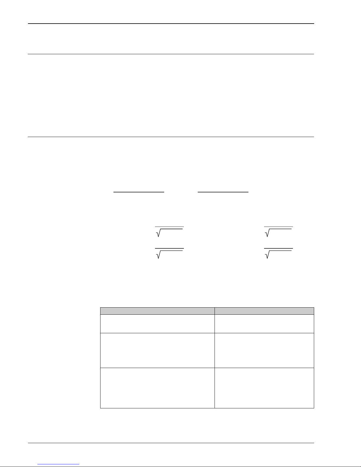
Measuring principle Vortex meters work on the principle of the Kármán vortex street. When fluid flows past a bluff body, vortices
are alternately formed on both sides with opposite directions of rotation. These vortices each generate a local
low pressure. The pressure fluctuations are recorded by the sensor and converted to electrical pulses. The
vortices develop very regularly within the permitted application limits of the device. Therefore, the frequency
of vortex shedding is proportional to the volume flow.
A0003938
The calibration factor (K-factor) is used as the proportional constant:
A0003939-en
• Within the application limits of the device, the K-factor only depends on the geometry of the device. It is
independent of the fluid velocity and the fluid properties viscosity and density. In this way, the K-factor is
also independent of the type of matter that is to be measured, regardless of whether this is steam, gas or
liquid.
• The primary measuring signal is already digital (frequency signal) and linear to the flow.
After production, the K-factor is determined in the factory by means of calibration and is not subject to longterm or zero-point drift.
• The device does not contain any moving parts and does not require maintenance.
v
K-Factor =
Pulses
Unit Volume [dm³]

Proline Prowirl 72F, 72W, 73F, 73W
4 Endress+Hauser
The capacitive sensor
The sensor of a vortex flowmeter has a major influence on the performance, robustness and reliability of the
whole measuring system.
The robust DSC sensor – with an integrated temperature measurement (Pt 1000) with Prowirl 73 –
is burst-tested and vibration and temperature-shock-tested (temperature shocks of 150 K/s). The Prowirl uses
the tried-and-tested capacitive measuring technology of Endress+Hauser applied in over 200 000 measuring
points worldwide.
The DSC (differential switched capacitance) sensor patented by Endress+Hauser has complete mechanical
balancing. It only reacts to the measured variable (vortex), not to vibrations. Even in the event of pipe
vibrations, the smallest of flows can be reliably measured at low density thanks to the unimpaired sensitivity of
the sensor. Thus, the wide turndown is also maintained even in the event of harsh operating conditions.
Vibrations up to 1 g, in frequencies up to 500 Hz in every axis (X, Y, Z), do not affect the flow measurement.
Due to its design, the capacitive sensor is also particularly mechanically resistant to temperature shocks and
water hammers in steam lines.
"Lifetime" calibration
Experience has shown that recalibrated Prowirl devices exhibit a very high degree of stability compared to their
original calibration: The recalibration values were all within the original measuring accuracy specifications of
the devices.
Various tests and simulation procedures carried out on devices by filing away the edges of Prowirl's bluff body
found that there was no negative impact on the accuracy up to a rounding diameter of 1 mm (0.04").
Generally the following statements are true:
• Experience has shown that if the fluid is non-abrasive and non-corrosive (e.g. most water and steam
applications), the meter's edges will never show rounding at the edges that is 1 mm (0.04") or more.
• If the rounding of the meter's edges is always 1 mm (0.04") or less, the meter will never show a calibration
shift that is out of the meter's original specifications.
• Typically, the bluff body's edges exhibit a small rounding that is less than 1 mm (0.04"). The meter, however,
is calibrated with this rounded edge. Therefore, the meter will stay within the tolerance specifications as long
as the additional wear and tear of the edge does not exceed an additional 1 mm (0.04").
Thus, the Prowirl product line offers calibration for life if the measuring device is used in non-abrasive and noncorrosive fluids.
A0003940-en
DSC sensor, Prowirl 72
A0004056-en
DSC sensor, Prowirl 73 with in tegrated temperature sensor
(Pt 1000)
Sensor
Seal
Y-Axis
X-Axis
Z-Axis
Sensor
Y-Axis
X-Axis
Z-Axis
Pt 1000
Proline Prowirl 72F, 72W, 73F, 73W
Endress+Hauser 5
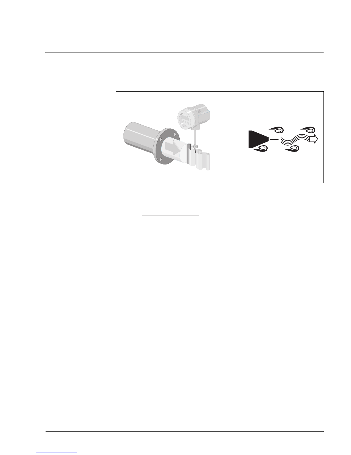
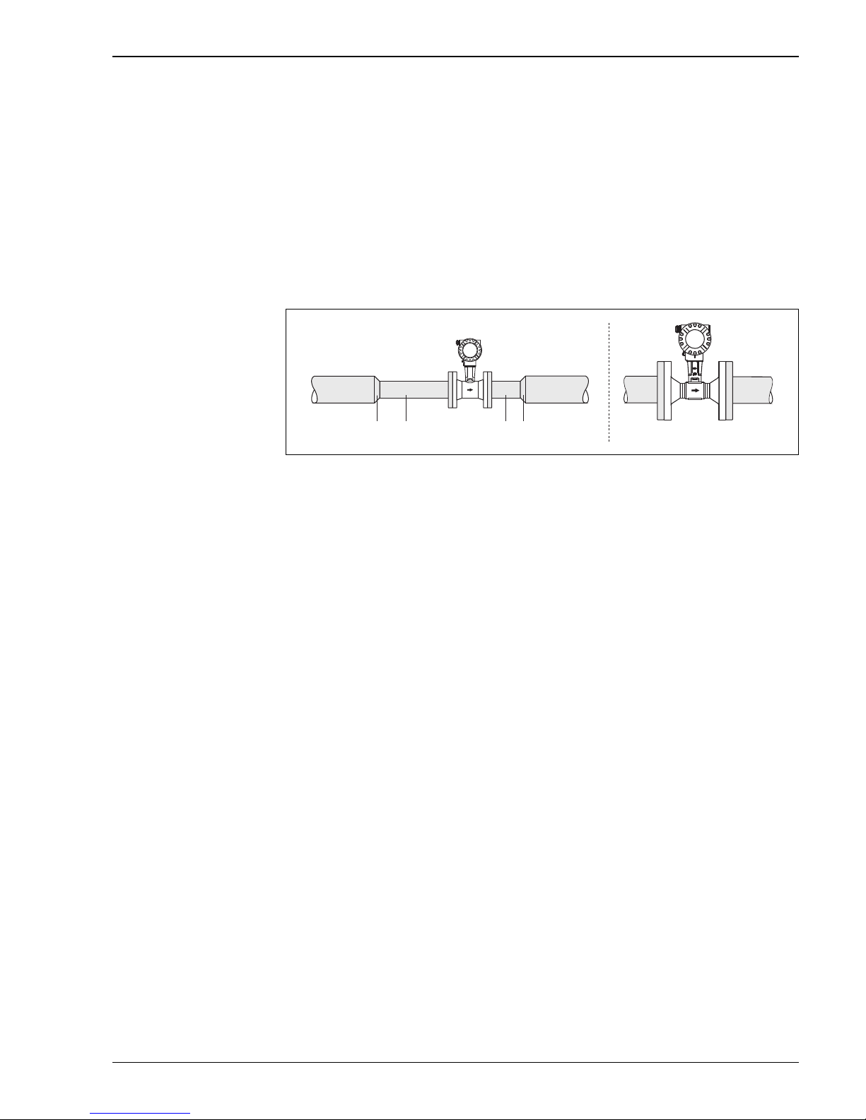
Sensor with integrated nominal diameter reduction
In many applications, the nominal diameter of the customer's pipe does not correspond to the nominal diameter
that is optimum for a vortex meter as the flow velocity is too low for vortex formation after the bluff body. This
is expressed in a signal loss in the lower flow range. To reduce the nominal diameter by one or two steps, and
thus increase the flow velocity, it is common practice nowadays to fit such measuring points with the following
adapters:
• Reducer (a)
• Straight pipe segment (b) as the inlet run (min. 15 × DN) in front of the vortex meter
• Straight pipe segment (c) as the outlet run (min. 5 × DN) after the vortex meter
• Expansion (d)
Endress+Hauser is now offering the Prowirl 72/73 vortex meter with integrated nominal diameter reduction
for such applications.
A0007142
Left: Traditional means for reducing pipeline section
Right: Nominal diameter reduction by using Prowirl with integrated line size reduction
Nomenclature for Prowirl vortex meters (flanged devices) with integrated nominal diameter reduction:
• Prowirl 72F/73F "R Style": single reduction of line size, e.g. from DN 80 (3") to DN 50 (2")
• Prowirl 72F/73F "S Style": double reduction of line size, e.g. from DN 80 (3") to DN 40 (1½")
(S = "super" reduced)
These models offer the following benefits:
• Cost and time saving as the adapter pieces with inlet and outlet runs are completely replaced by one single
device (additional inlet and outlet runs to be considered ä 25)
• Measuring range extended for lower flow rates
• Lower risk (of incorrect measuring device layout) in the planning phase as R Style and S Style measuring
devices have the same lengths as standard flanged devices. Each device type can be used alternatively
without making complicated changes to the layout.
• Accuracy specifications identical to those for standard devices
Temperature measurement (Prowirl 73)
In addition to the volume flow, the Prowirl 73 also measures the fluid temperature. The temperature is
measured by means of a temperature sensor Pt 1000 which is located in the paddle of the DSC sensor,
i.e. directly in the fluid ( ä 4).
Flow computer (Prowirl 73)
The electronics of the Prowirl 73 have an integral flow computer. With the aid of this flow computer other
process variables can be calculated from the primary measured variables (volume flow and temperature), e.g.:
• The mass flow and heat flow of saturated steam and water in accordance with IAPWS-IF97/ASME
• The mass flow and heat flow of superheated steam (at constant pressure or pressure read in via HART/
PROFIBUS PA/FOUNDATION Fieldbus) in accordance with IAPWS-IF97/ASME
• The mass flow and corrected volume flow of gases (at constant pressure or pressure read in via HART/
PROFIBUS PA/FOUNDATION Fieldbus), e.g. compressed air and natural gas AGA NX-19, AGA8-DC92,
ISO12213-2, AGA8 Gross Method 1 and SGERG-88 (see below). Additional gases can be programmed using
the real gas equation.
a
b
c d

Proline Prowirl 72F, 72W, 73F, 73W
6 Endress+Hauser
In the case of 4 to 20mA HART devices, the following gases are preprogrammed:
The heat flow (energy) of these gases is calculated as per ISO 6976 - based on the net calorific value or gross
calorific value.
• Optional with PROFIBUS PA and FOUNDATION Fieldbus: natural gas AGA NX-19 (corrected volume flow
and mass flow);
Optional for 4 to 20 mA HART: natural gas AGA NX-19, AGA8-DC92, ISO 12213-2, AGA8 Gross Method1,
SGERG-88 (corrected volume flow, mass flow, heat flow).
For natural gas AGA NX-19, AGA8 Gross Method 1 and SGERG-88, the gross calorific value or the net
calorific value can be entered to calculate the heat flow (energy). For AGA8-DC92 and ISO 12213-2, the
data for the gross calorific value and net calorific value are stored in the device according ISO 6976.
• The mass flow of any liquid (linear equation). The gross calorific value or the net calorific value can be
entered to calculate the heat flow (energy).
• Delta heat between saturated steam and condensate (second temperature value read in via HART) in
accordance with IAPWS-IF97/ASME.
• Delta heat between warm water and cold water (second temperature value read in via HART) in accordance
with IAPWS-IF97/ASME.
• In saturated steam measurements, the pressure of the steam can also be calculated from the measured
temperature and output in accordance with IAPWS-IF97/ASME.
The mass flow is calculated as the product of (volume flow × operating density). In the case of saturated steam,
water and other liquids, the operating density is a function of the temperature. In the case of superheated steam
and all other gases, the operating density is a function of the temperature and pressure.
The corrected volume flow is calculated as the product of (volume flow × operating density), divided by the
reference density. In the case of water and other liquids, the operating density is a function of the temperature.
In the case of all other gases, the operating density is a function of the temperature and pressure.
The heat flow is calculated as the product of (volume flow × operating density × specific enthalpy). In the case
of saturated steam and water, the operating density is a function of the temperature. In the case of superheated
steam, natural gas NX-19, natural gas AGA8-DC92, natural gas ISO 12213-2, natural gas AGA8 Gross Method
1 and natural gas SGERG-88, the operating density is a function of the temperature and pressure.
Diagnostic functions (Prowirl 73)
Extensive diagnostic options, such as retracing fluid and ambient temperatures, extreme flows etc., are also
optionally available for the measuring device.
Ammonia Helium 4 Nitrogen
Argon Hydrogen (normal) Oxygen
Butane Hydrogen chloride Propane
Carbon dioxide Hydrogen sulfide Xenon
Chlorine Krypton Mixtures of up to 8 components of
these gases
Ethane Methane
Ethylene (ethene) Neon
Proline Prowirl 72F, 72W, 73F, 73W
Endress+Hauser 7
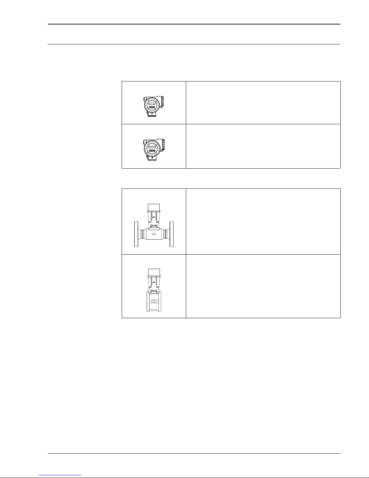
Measuring system The measuring system comprises a sensor and a transmitter. Two versions are available:
• Compact version: sensor and transmitter form a mechanical unit.
• Remote version: sensor is mounted separate from the transmitter (up to max. 30 m / 98 ft).
Transmitter
Sensor
Prowirl 72
A0009906
• Two-line liquid crystal display
• Configuration using pushbuttons
• Quick Setup for rapid commissioning
• Volume flow and calculated variables (mass flow or corrected volume flow)
Prowirl 73
A0009906
• Two-line liquid crystal display
• Configuration using pushbuttons
• Quick Setup for rapid commissioning
• Volume flow and temperature as well as calculated variables (mass flow, heat flow
or corrected volume flow)
F
A0009921
• Flanged version
• Range of nominal diameters DN 15 to 300 (½ to 12")
• Material of measuring tube: e.g.
– Stainless steel, A351-CF3M
– Alloy C-22 (only for Prowirl 72)
W
A0009922
• Wafer version (flangeless version)
• Range of nominal diameters DN 15 to 150 (½ to 6")
• Material of measuring tube: e.g. stainless steel, A351-CF3M
Esc
E
-
+
Esc
E
-
+
Proline Prowirl 72F, 72W, 73F, 73W
8 Endress+Hauser
Input
Measured variable Prowirl 72
• Volumetric flow (volume flow) is proportional to the frequency of vortex shedding after the bluff body.
• The following can be output as the output variable:
– Volume flow
– Mass flow or corrected volume flow (if process conditions are constant)
Prowirl 73
• Volumetric flow (volume flow) is proportional to the frequency of vortex shedding after the bluff body.
• The temperature can be output directly and is used to calculate the mass flow for example.
• The following can be output as the output variable:
– The measured process variables volume flow and temperature
– The calculated process variables mass flow, heat flow or corrected volume flow
Measuring range The measuring range depends on the fluid and the nominal diameter.
Start of measuring range
Depends on the density and the Reynolds number (Re
min
= 4000, Re
linear
= 20 000).
The Reynolds number is dimensionless and is the ratio of inertial forces to viscous forces of the fluid. It is used
for characterizing the flow. The Reynolds number is calculated as follows:
A0003794
Re = Reynolds number; Q = flow; di = internal diameter; = dynamic viscosity, = density
A0003239
* with amplification 5
Full scale value
Liquids: v
max
= 9 m/s (30 ft/s)
Gas/steam: see table
!
Note!
By using the selection and planning program "Applicator", you can determine the exact values for the fluid you
use. You can obtain the Applicator from your Endress+Hauser sales center or on the Internet under
www.endress.com.
Re
=
4·Q · m³[m³/s] [kg/ ]r
di [m] · µp · [Pa·s]
Re
=
4·Q · ³[ft³/s] [lb/ft ]r
di [ft] · µp · [0.001 cP]
Re
=
4·Q · m³[m³/s] [kg/ ]r
di [m] · µp · [Pa·s]
v
½…1"
®
=
min.
4.92
r [lb/ft³]
v
1½…12"
® =
min.
5.74
r [lb/ft³]
[ft/s] [ft/s]
v
DN 15…25
®
=
min.
6
r [kg/m³]
v
DN 40…300
® =
min.
7
r [kg/m³]
[m/s] [m/s]
*
*
*
*
Nominal diameter v
max
Standard version: DN 15 (½")
R Style: DN 25 (1") > DN 15 (½")
S Style: DN 40 (1½") >> DN 15 (½")
46 m/s (151 ft/s) or Mach 0.3
(depending on which value is smaller)
Standard version: DN 25 (1"), DN 40 (1½")
R Style:
– DN 40 (1½") > DN 25 (1")
– DN 50 (2") > DN 40 (1½")
S Style:
– DN 80 (3") >> DN 40 (1½")
75 m/s (246 ft/s) or Mach 0.3
(depending on which value is smaller)
Standard version: DN 50 to 300 (2 to 12")
R Style:
– DN 80 (3") > DN 50 (2")
– Nominal diameters larger than DN 80 (3")
S Style:
– DN 100 (4") >> DN 50 (2")
– Nominal diameters larger than DN 100 (4")
120 m/s (394 ft/s) or Mach 0.3
(depending on which value is smaller)
Calibrated range: up to 75 m/s (246 ft/s)

Proline Prowirl 72F, 72W, 73F, 73W
Endress+Hauser 9
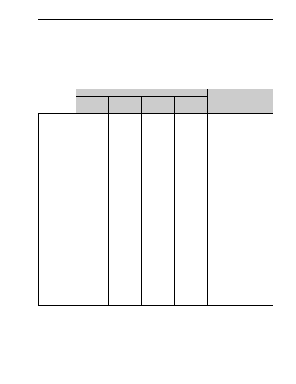
K-factor range
The table is used for orientation purposes. The range in which the K-factor can be is indicated for individual
nominal diameters and designs.
Measuring range for gases [m³/h or Nm³/h]
In the case of gases, the start of the measuring range depends on the density. With ideal gases, the density []
or corrected density [
N
] can be calculated using the following formulae:
A0003946
The following formulae can be used to calculate the volume [Q ] or corrected volume [ QN] in the case of ideal
gases:
A0003941
T = Operating temperature, P = operating pressure
Nominal diameter K-factor range (pulses/dm)
DIN/JIS ANSI 72F / 73F 72W / 73W
DN 15 ½" 390 to 450 245 to 280
DN 25 1" 70 to 85 48 to 55
DN 40 1½" 18 to 22 14 to 17
DN 50 2" 8 to 11 6 to 8
DN 80 3" 2.5 to 3.2 1.9 to 2.4
DN 100 4" 1.1 to 1.4 0.9 to 1.1
DN 150 6" 0.3 to 0.4 0.27 to 0.32
DN 200 8" 0.1266 to 0.1400 –
DN 250 10" 0.0677 to 0.0748 –
DN 300 12" 0.0364 to 0.0402 –
r [kg/m³] =
[kg/Nm³] · P [bar abs] · 273.15 [K]
N
r
T [K] · 1.013 [bar abs]
[kg/Nm³] =
[kg/m³] · T [K] · 1.013 [bar abs]
N
r
r
P [bar abs] · 273.15 [K]
r [kg/m³] =
[kg/Nm³] · P [bar abs] · 273.15 [K]
N
r
T [K] · 1.013 [bar abs]
[kg/Nm³] =
[kg/m³] · T [K] · 1.013 [bar abs]
N
r
r
P [bar abs] · 273.15 [K]
r [lb/ft³] =
[lb/SCF] · P [psia] · 530 [°R]
N
r
T [°F + 460] · 14.7 [psia]
[lb/SCF] =
[lb/ft³] · T [°F + 460] · 14.7 [psia]
N
r
r
P [psia] · 530 [°R]
[Nm³/h] =
N
Q
[m³/h] · P [bar abs] · 273.15 [K]Q
T [K] · 1.013 [bar abs]
Q [m³/h] =
N
[Nm³/h] · T [K] · 1.013 [bar abs]
Q
P [bar abs] · 273.15 [K]
[Nm³/h] =
N
Q
[m³/h] · P [bar abs] · 273.15 [K]Q
T [K] · 1.013 [bar abs]
Q [m³/h] =
N
[Nm³/h] · T [K] · 1.013 [bar abs]
Q
P [bar abs] · 273.15 [K]
[SCF/h] =
N
Q
[ft³/h] · P [psia] · 530 [°R]Q
T [°F + 460] · 14.7 [psia]
Q [ft³/h] =
N
[SCF/h] · T [°F + 460] · 14.7 [psia]
Q
P [psia] · 530 [°R]

Proline Prowirl 72F, 72W, 73F, 73W
10 Endress+Hauser
Input signal HART input functionality (Prowirl 73)
Prowirl 73 (4 to 20 mA HART) is able to read in an external pressure, temperature or density value. The
following order options are required for this purpose:
• Prowirl 73: output/input option W (4–20 mA HART) or A (4–20 mA HART + frequency)
•2 active barrier RN221N–x1 (for x: A = for non-hazardous areas, B = ATEX, C = FM, D = CSA)
• If reading in pressure: 1 Cerabar M or Cerabar S in burst mode (Activated burst mode must be noted with
the order of the Cerabar M or S. Otherwise the burst mode must be activated locally either with FieldCare
or with a HART handheld (FieldXpert).)
When this functionality is used, the following signals can be made available to the control system, e.g. in an
application with superheated steam:
• Pressure as 4 to 20 mA signal
•Temperature
• Mass flow
Pressure input (PROFIBUS PA, FOUNDATION Fieldbus)
An external pressure value function block can be read in with Prowirl 73 (bus version). The following order
options are required for this purpose:
PROFIBUS PA:
• Prowirl 73 output/input option H (PROFIBUS PA)
• Cerabar M electronics/display option P or R; ceramic sensor option 2F, 2H, 2M, 2P or 2S
Cerabar S Evolution output/operation option M, N or O; d:sensor range option 2C, 2E, 2F, 2H,
2K, 2M, 2P or 2S
FOUNDATION Fieldbus (FF):
• Prowirl 73 output/input option K (FOUNDATION Fieldbus)
• Cerabar S Evolution output/operation option P, Q or R; d:sensor range option 2C, 2E, 2F, 2H,
2K, 2M, 2P or 2S
Proline Prowirl 72F, 72W, 73F, 73W
Endress+Hauser 11
Output
Prowirl 72
By means of the outputs in the 4 to 20 mA/HART version of Prowirl 72, the volume flow and, if process
conditions are constant, the calculated mass flow and corrected volume flow can be output via the current
output and optionally via the pulse output or as a limit value via the status output.
Prowirl 73
By means of the outputs in the 4 to 20 mA/HART version of Prowirl 73, the following measured variables can
generally be output:
4 to 20 mA HART measuring devices
PROFIBUS - PA
(4 AI Blocks)
FOUNDATION
Fieldbus FF
(7 AI Blocks)
Current output
Frequency output
(only for output
option A)
Pulse output
(only for output
option A)
Status output
(only for output
option A)
Saturated steam
• Volume flow/mass
flow/heat flow
• Temperature
• Saturation steam
pressure
• Volume flow/mass
flow/heat flow
• Temperature
• Saturation steam
pressure
•Volume
•Mass
•Heat
• Volume flow/mass
flow/heat flow
limit value
• Temperature limit
value
• Totalizer limit
value
• Velocity limit value
•Calculated
saturated steam
pressure limit value
• Volume flow/mass
flow/heat flow
• Temperature
• Saturation steam
pressure
• Specific enthalpy
•Frequency
• Flow velocity
• Totalizer
• Optional:
–Reynolds
number
– Electronics
temperature
• Volume flow/mass
flow/heat flow
• Temperature
• Saturation steam
pressure
• Specific enthalpy
•Frequency
• Flow velocity
• Totalizer
• Optional:
–Reynolds
number
– Electronics
temperature
Superheated steam
• Volume flow/mass
flow/heat flow
• Temperature
• External pressure
(if it can be read in)
• Volume flow/mass
flow/heat flow
• Temperature
• External pressure
(if it can be read in)
•Volume
•Mass
•Heat
• Volume flow/mass
flow/heat flow
limit value
• Temperature limit
value
• Totalizer limit
value
• Velocity limit value
• External pressure
limit value (if it can
be read in)
• Volume flow/mass
flow/heat flow
• Temperature
• Specific enthalpy
•Frequency
• Flow velocity
• Totalizer
• Optional:
–Reynolds
number
– Electronics
temperature
• Volume flow/mass
flow/heat flow
• Temperature
• Specific enthalpy
•Frequency
• Flow velocity
• Totalizer
• Optional:
–Reynolds
number
– Electronics
temperature
Water
• Volume flow/mass
flow/heat flow/
corrected volume
flow
• Temperature
• External pressure
(if it can be read in)
• Volume flow/mass
flow/heat flow/
corrected volume
flow
•
Temperature
• External pressure
(if it can be read in)
•Volume
•Mass
•Heat
•Corrected volume
• Volume flow/mass
flow/heat flow/
corrected volume
flow limit value
• Temperature limit
value
• Totalizer limit
value
• Velocity limit value
• External pressure
limit value (if it can
be read in)
• Volume flow/mass
flow/heat flow/
corrected volume
flow
• Temperature
• Specific enthalpy
•Frequency
• Flow velocity
• Totalizer
• Optional:
–Reynolds
number
– Electronics
temperature
• Volume flow/mass
flow/heat flow/
corrected volume
flow
• Temperature
• Specific enthalpy
•Frequency
• Flow velocity
• Totalizer
• Optional:
–Reynolds
number
– Electronics
temperature

Proline Prowirl 72F, 72W, 73F, 73W
12 Endress+Hauser
Compressed air
• Volume flow/mass
flow/heat flow/
corrected volume
flow
• Temperature
• External pressure
(if it can be read in)
• Volume flow/mass
flow/heat flow/
corrected volume
flow
• Temperature
• External pressure
(if it can be read in)
•Volume
•Mass
•Corrected volume
• Volume flow/mass
flow/heat flow/
corrected volume
flow limit value
• Temperature limit
value
• Totalizer limit
value
• Velocity limit value
• External pressure
limit value (if it can
be read in)
• Volume flow/mass
flow/corrected
volume flow
• Temperature
• Compressibility
•Frequency
• Flow velocity
• Totalizer
• Optional:
–Reynolds
number
– Electronics
temperature
• Volume flow/mass
flow/corrected
volume flow
• Temperature
• Compressibility
•Frequency
• Flow velocity
• Totalizer
• Optional:
–Reynolds
number
– Electronics
temperature
Ar, NH3, C4H10,
CO2, CO, Cl2, C2H6,
C2H4, He 4, H2
(normal), HCl, H2S,
Kr, CH4, Ne, N2, O2,
C3H8, Xe*
• Volume flow/mass
flow/heat flow/
corrected volume
flow
• Temperature
• External pressure
(if it can be read in)
• Volume flow/mass
flow/heat flow/
corrected volume
flow
• Temperature
• External pressure
(if it can be read in)
•Volume
•Mass
•Heat
•Corrected volume
• Volume flow/mass
flow/corrected
volume flow limit
value
• Temperature limit
value
• Totalizer limit
value
• Velocity limit value
• External pressure
limit value (if it can
be read in)
No data
Use real gas
equation
No data
Use real gas
equation
Mixtures of up to 8 of
the components above
• Volume flow/mass
flow/heat flow/
corrected volume
flow
• Temperature
• External pressure
(if it can be read in)
• Volume flow/mass
flow/heat flow/
corrected volume
flow
• Temperature
• External pressure
(if it can be read in)
•Volume
•Mass
•H
eat
•Corrected volume
• Volume flow/mass
flow/corrected
volume flow limit
value
• Temperature limit
value
• Totalizer limit
value
• Velocity limit value
• External pressure
limit value (if it can
be read in)
No data
Use real gas
equation
No data
Use real gas
equation
Real gas equation
• Volume flow/mass
flow/corrected
volume flow
• Temperature
• External pressure
(if it can be read in)
• Volume flow/mass
flow/corrected
volume flow
• Temperature
• External pressure
(if it can be read in)
•Volume
•Mass
•Corrected volume
• Volume flow/mass
flow/corrected
volume flow limit
value
• Temperature limit
value
• Totalizer limit
value
• Velocity limit value
• External pressure
limit value (if it can
be read in)
• Volume flow/mass
flow/corrected
volume flow
• Temperature
•Frequency
• Flow velocity
• Totalizer
• Optional:
electronics
temperature
• Volume flow/mass
flow/corrected
volume flow
• Temperature
•Frequency
• Flow velocity
• Totalizer
• Optional:
electronics
temperature
* Argon, ammonia, butane, carbon dioxide, carbon monoxide, chlorine, ethane, ethylene (ethene), helium 4, hydrogen (normal), hydrogen chloride, hydrogen
sulfide, krypton, methane, neon, nitrogen, oxygen, propane, xenon
4 to 20 mA HART measuring devices
PROFIBUS - PA
(4 AI Blocks)
FOUNDATION
Fieldbus FF
(7 AI Blocks)
Current output
Frequency output
(only for output
option A)
Pulse output
(only for output
option A)
Status output
(only for output
option A)

Proline Prowirl 72F, 72W, 73F, 73W
Endress+Hauser 13
Natural gas AGA NX19
• Volume flow/mass
flow/heat flow/
corrected volume
flow
• Temperature
• External pressure
(if it can be read in)
• Volume flow/mass
flow/heat flow/
corrected volume
flow
• Temperature
• External pressure
(if it can be read in)
•Volume
•Mass
•Heat
•Corrected volume
• Volume flow/mass
flow/corrected
volume flow limit
value
• Temperature limit
value
• Totalizer limit
value
• Velocity limit value
• External pressure
limit value (if it can
be read in)
• Volume flow/mass
flow/corrected
volume flow
• Temperature
• Supercompressibility
•Frequency
• Flow velocity
• Totalizer
• Optional:
–Reynolds
number
– Electronics
temperature
• Volume flow/mass
flow/corrected
volume flow
• Temperature
• Supercompressibility
•Frequency
• Flow velocity
• Totalizer
• Optional:
–Reynolds
number
– Electronics
temperature
Natural gas
AGA8-DC92 detailed
method
• Volume flow/mass
flow/heat flow/
corrected volume
flow
• Temperature
• External pressure
(if it can be read in)
• Volume flow/mass
flow/heat flow/
corrected volume
flow
• Temperature
• External pressure
(if it can be read in)
•Volume
•Mass
•Heat
•Corrected volume
• Volume flow/mass
flow/heat flow/
corrected volume
flow limit value
• Temperature limit
value
• Totalizer limit
value
• Velocity limit value
• External pressure
limit value (if it can
be read in)
No data
Use natural gas
AGA NX-19 or real
gas equation
No data
Use natural gas
AGA NX-19 or real
gas equation
Natural gas
ISO 12213-2
• Volume flow/mass
flow/heat flow/
corrected volume
flow
•
Temperature
• External pressure
(if it can be read in)
• Volume flow/mass
flow/heat flow/
corrected volume
flow
• Temperature
• External pressure
(if it can be read in)
•Volume
•Mass
•Heat
•Corrected volume
• Volume flow/mass
flow/heat flow/
corrected volume
flow limit value
• Temperature limit
value
• Totalizer limit
value
• Velocity limit value
• External pressure
limit value (if it can
be read in)
No data
Use natural gas
AGA NX-19 or real
gas equation
No data
Use natural gas
AGA NX-19 or real
gas equation
Natural gas AGA8
Gross Method 1
• Volume flow/mass
flow/heat flow/
corrected volume
flow
• Temperature
• External pressure
(if it can be read in)
• Volume flow/mass
flow/heat flow/
corrected volume
flow
• Temperature
• External pressure
(if it can be read in)
•Volume
•Mass
•Heat
•Corrected volume
• Volume flow/mass
flow/heat flow/
corrected volume
flow limit value
• Temperature limit
value
• Totalizer limit
value
• Velocity limit value
• External pressure
limit value (if it can
be read in)
No data
Use natural gas
AGA NX-19 or real
gas equation
No data
Use natural gas
AGA NX-19 or real
gas equation
* Argon, ammonia, butane, carbon dioxide, carbon monoxide, chlorine, ethane, ethylene (ethene), helium 4, hydrogen (normal), hydrogen chloride, hydrogen
sulfide, krypton, methane, neon, nitrogen, oxygen, propane, xenon
4 to 20 mA HART measuring devices
PROFIBUS - PA
(4 AI Blocks)
FOUNDATION
Fieldbus FF
(7 AI Blocks)
Current output
Frequency output
(only for output
option A)
Pulse output
(only for output
option A)
Status output
(only for output
option A)

Proline Prowirl 72F, 72W, 73F, 73W
14 Endress+Hauser
If configured, the following calculated measured variables can also be displayed via the local display in
Prowirl 73:
•Density
• Specific enthalpy
• Saturation steam pressure (for saturated steam)
•Z-factor
• Flow velocity
Natural gas SGERG-88
• Volume flow/mass
flow/heat flow/
corrected volume
flow
• Temperature
• External pressure
(if it can be read in)
• Volume flow/mass
flow/heat flow/
corrected volume
flow
• Temperature
• External pressure
(if it can be read in)
•Volume
•Mass
•Heat
•Corrected volume
• Volume flow/mass
flow/heat flow/
corrected volume
flow limit value
• Temperature limit
value
• Totalizer limit
value
• Velocity limit value
• External pressure
limit value (if it can
be read in)
No data
Use natural gas
AGA NX-19 or real
gas equation
No data
Use natural gas
AGA NX-19 or real
gas equation
User-defined liquid
• Volume flow/mass
flow/heat flow/
corrected volume
flow
• Temperature
• Volume flow/mass
flow/heat flow/
corrected volume
flow
• Temperature
•Volume
•Mass
•Heat
•Corrected volume
• Volume flow/mass
flow/corrected
volume flow limit
value
• Temperature limit
value
• Totalizer limit
value
• Velocity limit value
• Volume flow/mass
flow/corrected
volume flow
• Temperature
•Frequency
• Flow velocity
• Totalizer
• Optional:
electronics
temperature
• Volume flow/mass
flow/corrected
volume flow
• Temperature
•Frequency
• Flow velocity
• Totalizer
• Optional:
electronics
temperature
Water delta heat
application
• Volume flow/mass
flow/heat flow/
corrected volume
flow
• Temperature
•External
temperature
• Volume flow/mass
flow/heat flow/
corrected volume
flow
• Temperature
•External
temperature
•Volume
•Mass
•Heat
•Corrected volume
• Volume flow/mass
flow/heat flow/
corrected volume
flow limit value
• Temperature limit
value
• Totalizer limit
value
• Velocity limit value
•External
temperature limit
va
lue
No data No data
Saturated steam delta
heat application
• Volume flow/mass
flow/heat flow
• Temperature
•External
temperature
• Volume flow/mass
flow/heat flow
• Temperature
•External
temperature
•Volume
•Mass
•Heat
• Volume flow/mass
flow/heat flow
limit value
• Temperature limit
value
• Totalizer limit
value
• Velocity limit value
•External
temperature limit
value
No data No data
* Argon, ammonia, butane, carbon dioxide, carbon monoxide, chlorine, ethane, ethylene (ethene), helium 4, hydrogen (normal), hydrogen chloride, hydrogen
sulfide, krypton, methane, neon, nitrogen, oxygen, propane, xenon
4 to 20 mA HART measuring devices
PROFIBUS - PA
(4 AI Blocks)
FOUNDATION
Fieldbus FF
(7 AI Blocks)
Current output
Frequency output
(only for output
option A)
Pulse output
(only for output
option A)
Status output
(only for output
option A)

Proline Prowirl 72F, 72W, 73F, 73W
Endress+Hauser 15
Output signal Prowirl 72
Current output:
• 4 to 20 mA with HART,
• Full scale value and time constant (0 to 100 s) can be set
Pulse/status output:
• Open collector, passive, galvanically isolated
– Non-Ex, Ex d/XP version: U
max
= 36 V, with 15 mA current limiting, Ri = 500
– Ex i/IS and Ex n version: U
max
= 30 V, with 15 mA current limiting, Ri = 500
The pulse/status output can be configured as:
• Pulse output:
– Pulse value and polarity can be selected
– Pulse width can be configured (0.005 to 2 s)
– Pulse frequency max. 100 Hz
• Status output:
Can be configured for error messages or flow limit values
• Vortex frequency:
– Direct output of unscaled vortex pulses 0.5 to 2850 Hz
(e.g. for connecting to an RMC621 flow computer)
– Pulse ratio 1:1
• PFM signal (pulse/frequency modulation):
With external connection via flow computer RMC621 or RMS621
PROFIBUS PA interface:
• PROFIBUS PA in accordance with EN 50170 Volume 2, IEC 61158-2 (MBP), galvanically isolated
• Current consumption = 16 mA
• Error current FDE (fault disconnection electronic) = 0 mA
• Data transmission rate: supported baudrate = 31.25 kBit/s
• Signal encoding = Manchester II
• Function blocks: 1 Analog Input, 1 totalizer
• Output data: volume flow, calculated mass flow, corrected volume flow, totalizer
• Input data: positive zero return (ON/OFF), totalizer control
• Bus address can be set at the device via DIP switches
FOUNDATION Fieldbus interface:
• FOUNDATION Fieldbus H1, IEC 61158-2, galvanically isolated
• Current consumption = 16 mA
• Error current FDE (fault disconnection electronic) = 0 mA
• Data transmission rate: supported baudrate = 31.25 kBit/s
• Signal encoding = Manchester II
• Function blocks: 2 Analog Input, 1 Discrete Output
• Output data: volume flow, calculated mass flow, corrected volume flow, totalizer
• Input data: positive zero return (ON/OFF), totalizer reset
• Link Master (LM) functionality is supported

Proline Prowirl 72F, 72W, 73F, 73W
16 Endress+Hauser
Prowirl 73
Current output:
• 4 to 20 mA with HART,
• Full scale value and time constant (0 to 100 s) can be set
Frequency output, pulse/status output:
• Frequency output (optional): open collector, passive, galvanically isolated
– Non-Ex, Ex d/XP version: U
max
= 36 V, with 15 mA current limiting, Ri = 500
– Ex i/IS and Ex n version: U
max
= 30 V, with 15 mA current limiting, Ri = 500
The pulse/status output can be configured as:
• Frequency output:
– End frequency 0 to 1000 Hz (fmax = 1250 Hz)
• Pulse output:
– Pulse value and polarity can be selected
– Pulse width can be configured (0.005 to 2 s)
– Pulse frequency max. 100 Hz
• Status output:
Can be configured for error messages or flow values, temperature values, pressure limit values
• Vortex frequency:
– Direct output of unscaled vortex pulses 0.5 to 2850 Hz
(e.g. for connecting to an RMC621 flow computer)
– Pulse ratio 1:1
PROFIBUS PA interface:
• PROFIBUS PA in accordance with EN 50170 Volume 2, IEC 61158-2 (MBP), galvanically isolated
• Current consumption = 16 mA
• Error current FDE (fault disconnection electronic) = 0 mA
• Data transmission rate: supported baudrate = 31.25 kBit/s
• Signal encoding = Manchester II
• Function blocks: 4 Analog Input, 2 totalizer
• Output data: volume flow, mass flow, corrected volume flow, heat flow, temperature, density, specific
enthalpy, calculated steam pressure (saturated steam), operating Z-factor, vortex frequency, electronics
temperature, Reynolds number, velocity, totalizer
• Input data: positive zero return (ON/OFF), totalizer control, absolute pressure, display value
• Bus address can be set at the device via DIP switches
FOUNDATION Fieldbus interface:
• FOUNDATION Fieldbus H1, IEC 61158-2, galvanically isolated
• Current consumption = 16 mA
• Error current FDE (fault disconnection electronic) = 0 mA
• Data transmission rate: supported baudrate = 31.25 kBit/s
• Signal encoding = Manchester II
• Function blocks: 6 Analog Input, 1 Discrete Output, 1 Analog Output
• Output data: volume flow, mass flow, corrected volume flow, heat flow, temperature, density, specific
enthalpy, calculated steam pressure (saturated steam), operating Z-factor, vortex frequency, electronics
temperature, Reynolds number, velocity, totalizer 1 + 2
• Input data: positive zero return (ON/OFF), totalizer reset, absolute pressure
• Link Master (LM) functionality is supported
Signal on alarm • Current output: error response can be selected (e.g. in accordance with NAMUR Recommendation NE 43)
• Pulse output: error response can be selected
• Status output: "not conducting" in event of fault
Proline Prowirl 72F, 72W, 73F, 73W
Endress+Hauser 17
Load
A0001921
The area shaded gray refers to the permitted load (for HART: min. 250 )
The load is calculated as follows:
R
B
Load, load resistance
U
S
Supply voltage: non-Ex = 12 to 36 V DC; Ex d /XP= 15 to 36 V DC; Ex i /IS and Ex n = 12 to 30 V DC
U
Kl
Terminal voltage: non-Ex = min. 12 V DC; Ex d/XP = min. 15 V DC; Ex i/IS and Ex n = min. 12 V DC
I
max
Output current (22.6 mA)
Low flow cut off Switch points for low flow cut off can be selected as required.
Galvanic isolation All electrical connections are galvanically isolated from one another.
00
100 100
200 200
300 300
400 400
500 500
600 600
700 700
800 800
900 900
1000 1000
1100 1100
BB
RR
[] []
10 1020 2025 2530 3036 3615 15
18
21
W
0
100
200
300
400
500
600
700
800
900
1000
1100
B
S
R
U
V
[]
[]
10
20 25 30
15
18
W
Ex i
Exi/Exn
W
Ex d
Ex
RB=
(U
SKl
– U )
(I )
max
-3
– 10 0.022
=
(U
SKl
– U )

Proline Prowirl 72F, 72W, 73F, 73W
18 Endress+Hauser
Power supply
Electrical connection
A0003392
A – HART: power supply, current output
– PROFIBUS PA: 1 = PA+, 2 = PA–
– FOUNDATION Fieldbus: 1 = FF+, 2 = FF–
B Optional pulse output (not for PROFIBUS PA and FOUNDATION Fieldbus), can also be operated as:
– Status output
– Only Prowirl 73: frequency output
– Only Prowirl 73: as a PFM output (pulse/frequency modulation) together with an RMC621 or
RMS621 flow computer
C Ground terminal (relevant for remote version)
D Only Prowirl 72: PFM (pulse/frequency modulation) wiring for connecting to flow computer RMC621 or RMS621
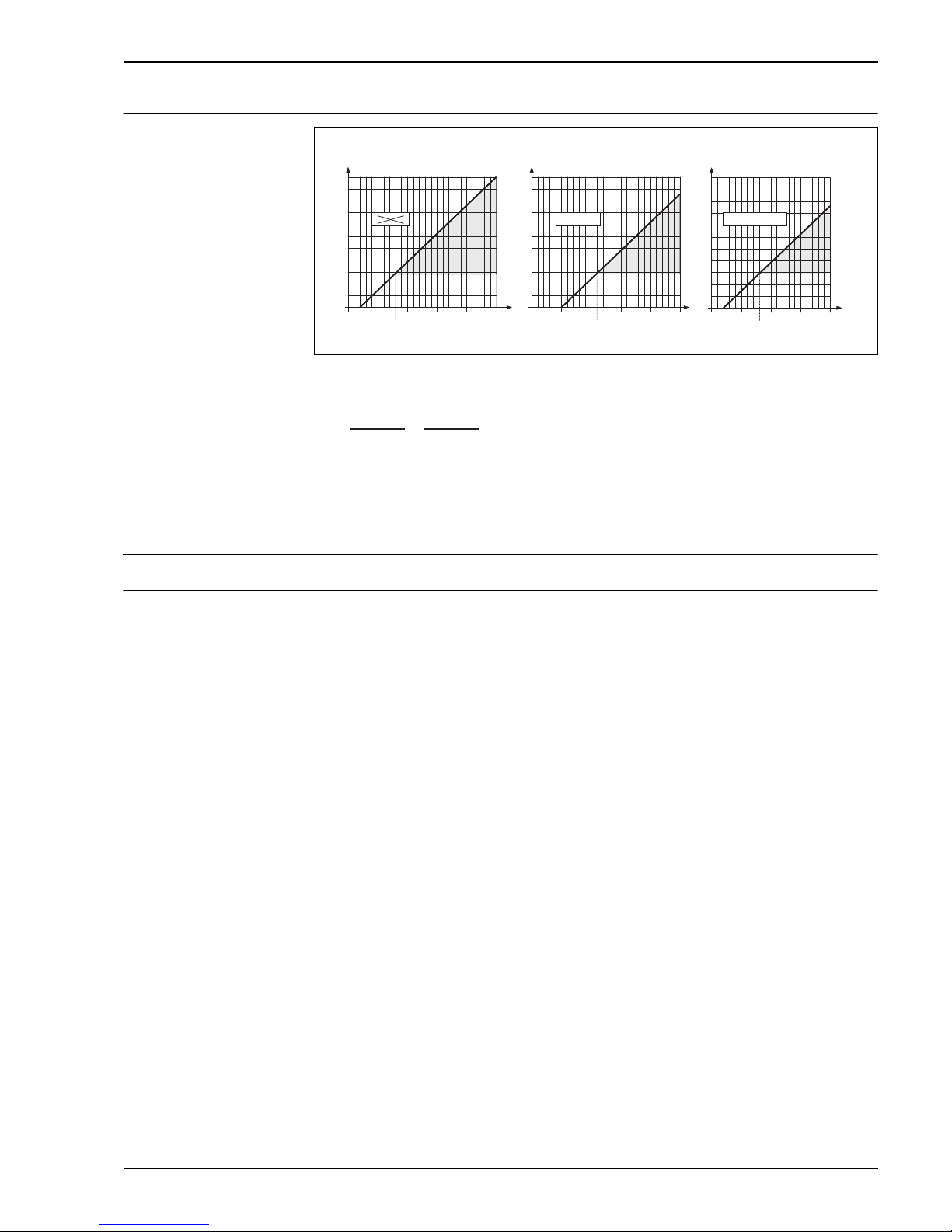
Wiring HART input
A0004215
1 Connection diagram for PLC with common "plus"
Dotted line = alternative wiring when only the signal of the Prowirl 73 is fed to the PLC.
2 Connection diagram for PLC with common "minus"
Dotted line = alternative wiring when only the signal of the Prowirl 73 is fed to the PLC.
3 Connection diagram without PLC
Dotted line = wiring without connection to external components (e.g. recorder, displays, Fieldgate, etc.)
A = Prowirl 73, B = pressure sensor (Cerabar M), C = temperature sensor (Omnigrad TR10) or other external measuring
devices (HART-enabled and burst-enabled), D = active barrier RN221N
12 1234 34
A
D
C
++++
----
C
B
1
2
3
C
1
2
AB
DD
1
1
2
2
1
2
I+ I–
I+
I–
D D
AB
C
1
2
1
2
I+ I–
I+
I–
250W
0+H
0–
0– 0+H0+0+
PLC+PLC (73) in PLC (p/T) in
PLC+
250W
0+
0+H
0– 0+
0+H
0–
PLC– PLC (73) in
PLC (p/T) inPLC–
250 W
0+
0+H
0– 0+
0+H
0–
–
+
–
+
Proline Prowirl 72F, 72W, 73F, 73W
Endress+Hauser 19
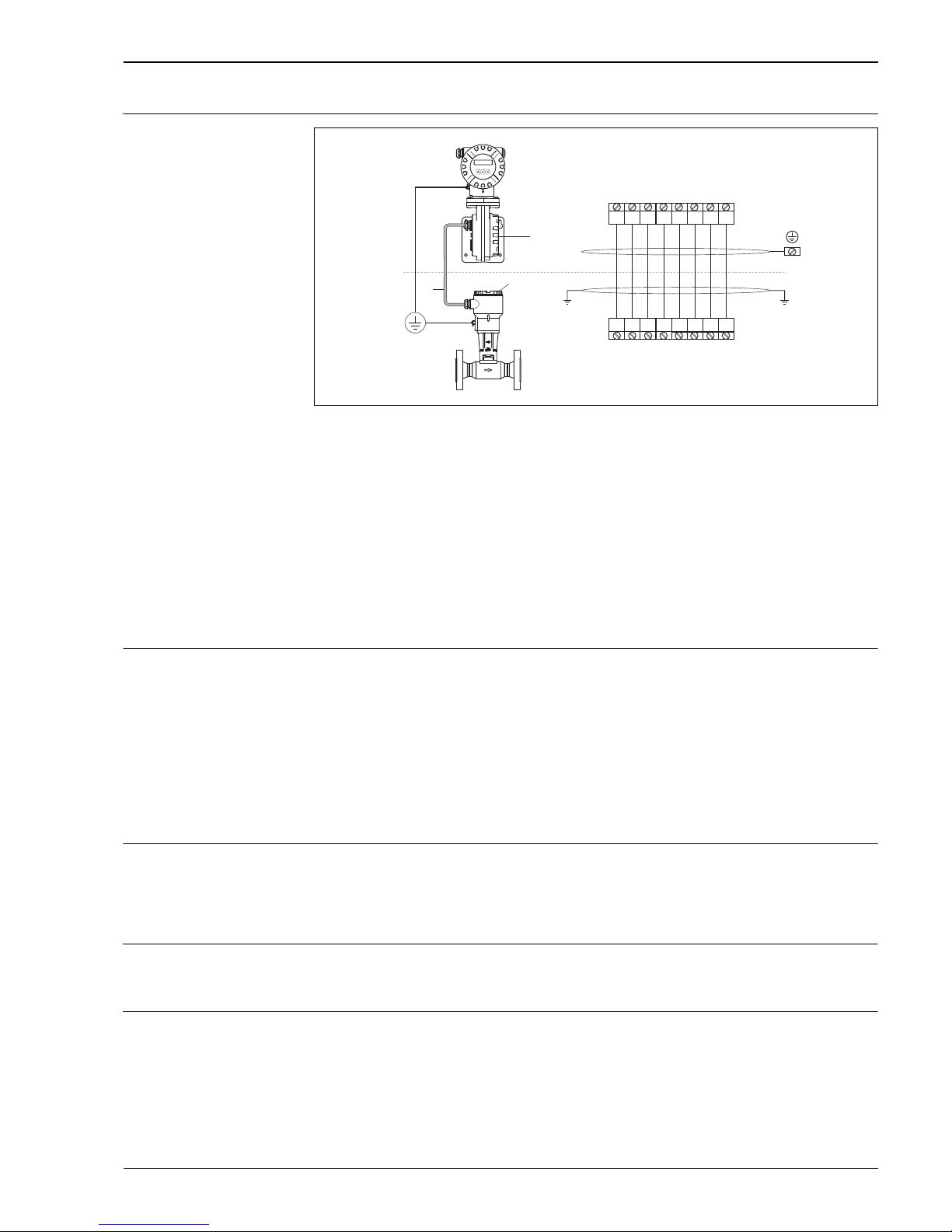
Wiring remote version
A0001893
Connecting the remote version
a = Connection compartment cover (transmitter)
b = Connection compartment cover (sensor)
c = Connecting cable (signal cable)
d = Identical potential matching for sensor and transmitter
e = Connect shielding to ground terminal in transmitter housing and keep as short as possible
f = Connect shielding to cable strain relief clamp in connection housing
Wire colors (color code according to DIN 47100):
Terminal number: 1 = white; 2 = brown; 3 = green; 4 = yellow, 5 = gray; 6 = pink; 7 = blue; 8 = red
Optionally available with armored signal cable. Been suitable for static laying and flexible applications with free movement
without tensile load and without obligatory guidance. For layings in dry and damp areas, in the soil as well as in the external
area.
Supply voltage HART:
• Non-Ex: 12 to 36 V DC (with HART: 18 to 36 V DC)
• Ex i/IS and Ex n: 12 to 30 V DC (with HART: 18 to 30 V DC)
• Ex d/XP: 15 to 36 V DC (with HART: 21 to 36 V DC)
PROFIBUS PA and FOUNDATION Fieldbus:
• Non-Ex: 9 to 32 V DC
• Ex i/IS and Ex n: 9 to 24 V DC
• Ex d/XP: 9 to 32 V DC
• Current consumption PROFIBUS PA: 16 mA, FOUNDATION Fieldbus: 16 mA
Cable entries Power supply and signal cables (outputs):
• Cable entry M20 1.5 (6 to 12 mm / 0.24 to 0.47")
• Cable entry M20 1.5 for armored signal cable (9.5 to 16 mm / 0.37 to 0.63")
• Thread for cable entry: ½" NPT, G ½", G ½" Shimada
• Fieldbus connector
Cable specifications Permitted temperature range:
• Standard cable: –40 °C (–40 °F) to maximum permissible ambient temperature plus 10 °C (18 °F)
• Armored cable: –30 to +70 °C (–22 to +158 °F)
Power supply failure • Totalizer stops at the last value determined.
• All settings are kept in the EEPROM.
• Error messages (incl. value of operated hours counter) are stored.
a
c
b
d
3
3
1
1
4
4
2
2
55667
7
8
8
DIFF +
DIFF +
DIFF –
DIFF –
GROUND
GROUND
+5VA
+5VA
–5VA
–5VA
TEMP 1
TEMP 1
TEMP 2
TEMP 2
TEMP 3
TEMP 3
e
f

Proline Prowirl 72F, 72W, 73F, 73W
20 Endress+Hauser
Performance characteristics
Reference operating
conditions
Error limits following ISO/DIN 11631:
• +20 to +30 °C (+68 to +86 °F)
• 2 to 4 bar (29 to 58 psi)
• Calibration rig traceable to national calibration standards
• Calibration with the process connection corresponding to the standard in question
Maximum measured error Prowirl 72
• Liquid:
< 0.75% o.r. for Re > 20000
< 0.75% o.f.s for Re between 4000 and 20000
• Gas/steam:
< 1% o.r. for Re > 20000 and v < 75 m/s (246 ft/s)
< 1% o.f.s for Re between 4000 and 20000
o.r. = of reading, o.f.s = of full scale value, Re = Reynolds number
Prowirl 73
• Volume flow (liquid):
< 0.75% o.r. for Re > 20000
< 0.75% o.f.s for Re between 4000 and 20000
• Volume flow (gas/steam):
< 1% o.r. for Re > 20000 and v < 75 m/s (246 ft/s)
< 1% o.f.s for Re between 4000 and 20000
•Temperature:
< 1°C / 1.8 °F (T > 100 °C / 212 °F, saturated steam and for liquids at ambient temperature);
< 1% o.r. [K] (gas)
Rise time 50% (agitated under water, following IEC 60751): 8 s
• Mass flow (saturated steam):
– For flow velocities 20 to 50 m/s (66 to 164 ft/s), T > 150 °C / 302 °F (423 K)
< 1.7% o.r. (2% o.r. for remote version) for Re > 20000
< 1.7% o.f.s (2% o.f.s for remote version) for Re between 4000 and 20000
– For flow velocities 10 to 70 m/s (33 to 230 ft/s), T > 140 °C / 284 °F (413 K)
< 2% o.r. (2.3% o.r. for remote version) for Re > 20000
< 2% o.f.s (2.3% o.f.s for remote version) for Re between 4000 and 20000
• Mass flow of superheated steam and gas (air, natural gas AGA NX-19, AGA8-DC92, ISO 12213-2, AGA8
Gross Method 1, SGERG-88, preprogrammed gases – does not apply to the real gas equation):
!
Note!
A Cerabar S device has to be used for the measuring errors listed below. The measured error used to calculate
the error in the measured pressure is 0.15%.
< 1.7% o.r. (2.0% o.r. for remote version) for Re > 20000 and process pressure < 40 bar abs (580 psi abs)
< 1.7% o.f.s. (2.0% for remote version) for Re between 4000 and 20000 and
process pressure < 40 bar abs (580 psi abs)
< 2.6% o.r. (2.9% o.r. for remote version) for Re > 20000 and process pressure < 120 bar abs (1740 psi abs)
< 2.6% o.f.s. (2.9% o.r. for remote version) for Re between 4000 and 20000 and
process pressure < 120 bar abs (1740 psi abs)
• Mass flow (water):
< 0.85% o.r. (1.15% o.r. for remote version) for Re > 20000
< 0.85% o.f.s (1.15% o.f.s for remote version) for Re between 4000 and 20000
• Mass flow (customer-defined liquids):
To specify the system accuracy, Endress+Hauser requires information on the type of liquid and its operating
temperature, or information in tabular form on the dependency between the liquid density and temperature.
Example: Acetone is to be measured at fluid temperatures between 70 and 90 °C (158 and 194 °F). The
parameters TEMPERATURE VALUE (here 80 °C / 176 °F), DENSITY VALUE (here 720.00 kg/m
) and
EXPANSION COEFFICIENT (here 18.0298 × 10E-4 1/°C) have to be entered in the transmitter for this
purpose. The overall system uncertainty, which is smaller than 0.9% for the example cited above, is made
up of the following measuring uncertainties: Uncertainty of volume flow measurement, uncertainty of
temperature measurement, uncertainty of the density-temperature correlation used (incl. the resulting
uncertainty of density).
 Loading...