

Endress+Hauser Proline Prowirl 72F, Proline Prowirl 72W, Proline Prowirl 73W, Proline Prowirl 73F User Manual
Page 1
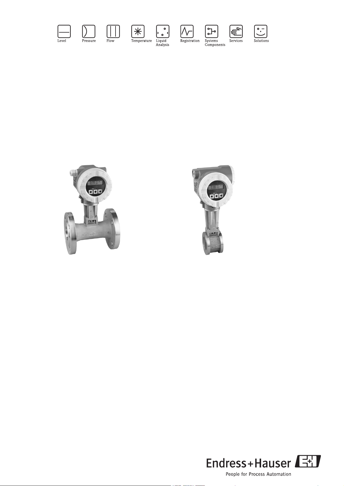
Technical Information
Proline Prowirl 72F, 72W, 73F, 73W
Vortex Flow Measuring System
Reliable flow measurement of gas, steam and liquids
Application
For the universal measurement of the volume flow
of gases, steam and liquids.
With integrated T-measurement, the mass flow of steam,
water (as per IAPWS-IF97 ASME), natural gas (as per
AGA NX-19), compressed air and other gases and liquids
can be measured.
Maximum range of applications thanks to:
• Fluid temperature range from –200...+400 °C
• Pressure ratings up to PN250/Cl 1500
Approvals for hazardous areas:
• ATEX, FM, CSA, TIIS
Connection to all common process control systems:
• HART, PROFIBUS PA, FOUNDATION Fieldbus
Relevant safety aspects:
• Pressure Equipment Directive
•Up to SIL 2
Your benefits
The robust Prowirl sensor, tried and tested in over
100,000 applications offers:
• High resistance to:
– Vibrations (over 1 g in all axes)
– Temperature shocks (> 150 K/s)
– Contaminated media
– Water hammer
• No maintenance, no moving parts, no zero-point drift.
• Software initial settings save time and costs
In addition, Prowirl devices offer the following
possibilities:
• Complete saturated steam or liquid-mass measuring
point in one single device
• Calculation of the mass flow from the measured
variables volume flow and temperature in the
integrated flow computer
• External pressure value read-in for superheated steam
and gas applications (optional)
• External temperature value read-in for delta heat
measurement (optional)
TI070D/06/en/12.05
71005481
Page 2
Table of contents
Proline Prowirl 72F, 72W, 73F, 73W
Function and system design. . . . . . . . . . . . . . . . . . . . . 3
Measuring principle . . . . . . . . . . . . . . . . . . . . . . . . . . . . . . . . . . . 3
Measuring system . . . . . . . . . . . . . . . . . . . . . . . . . . . . . . . . . . . . . 5
Input . . . . . . . . . . . . . . . . . . . . . . . . . . . . . . . . . . . . . . 5
Measured variable . . . . . . . . . . . . . . . . . . . . . . . . . . . . . . . . . . . . 5
Measuring range . . . . . . . . . . . . . . . . . . . . . . . . . . . . . . . . . . . . . . 5
Output . . . . . . . . . . . . . . . . . . . . . . . . . . . . . . . . . . . . . 6
Output signal . . . . . . . . . . . . . . . . . . . . . . . . . . . . . . . . . . . . . . . . 7
Signal on alarm . . . . . . . . . . . . . . . . . . . . . . . . . . . . . . . . . . . . . . 9
Load . . . . . . . . . . . . . . . . . . . . . . . . . . . . . . . . . . . . . . . . . . . . . . 9
Low flow cut off . . . . . . . . . . . . . . . . . . . . . . . . . . . . . . . . . . . . . . 9
Galvanic isolation . . . . . . . . . . . . . . . . . . . . . . . . . . . . . . . . . . . . . 9
Power supply . . . . . . . . . . . . . . . . . . . . . . . . . . . . . . . 10
Electrical connection . . . . . . . . . . . . . . . . . . . . . . . . . . . . . . . . . 10
Wiring when using the HART input . . . . . . . . . . . . . . . . . . . . . 10
Wiring (remote version) . . . . . . . . . . . . . . . . . . . . . . . . . . . . . . 11
Supply voltage . . . . . . . . . . . . . . . . . . . . . . . . . . . . . . . . . . . . . . 11
Cable entry . . . . . . . . . . . . . . . . . . . . . . . . . . . . . . . . . . . . . . . . 11
Power supply failure . . . . . . . . . . . . . . . . . . . . . . . . . . . . . . . . . . 11
Performance characteristics. . . . . . . . . . . . . . . . . . . . 12
Reference operating conditions . . . . . . . . . . . . . . . . . . . . . . . . . . 12
Maximum measured error . . . . . . . . . . . . . . . . . . . . . . . . . . . . . 12
Repeatability . . . . . . . . . . . . . . . . . . . . . . . . . . . . . . . . . . . . . . . . 12
Reaction time/step response time . . . . . . . . . . . . . . . . . . . . . . . 12
Influence of ambiente temperature . . . . . . . . . . . . . . . . . . . . . . . 12
Certificates and approvals . . . . . . . . . . . . . . . . . . . . . 31
CE mark . . . . . . . . . . . . . . . . . . . . . . . . . . . . . . . . . . . . . . . . . . 31
C-tick . . . . . . . . . . . . . . . . . . . . . . . . . . . . . . . . . . . . . . . . . . . . 31
Ex-approval . . . . . . . . . . . . . . . . . . . . . . . . . . . . . . . . . . . . . . . . 31
Pressure measuring device approval . . . . . . . . . . . . . . . . . . . . . . 31
Certification FOUNDATION Fieldbus . . . . . . . . . . . . . . . . . . . . . 31
Certification PROFIBUS PA . . . . . . . . . . . . . . . . . . . . . . . . . . . . 31
Other standards and guidelines . . . . . . . . . . . . . . . . . . . . . . . . . . 32
Functional safety . . . . . . . . . . . . . . . . . . . . . . . . . . . . . . . . . . . 32
Ordering information . . . . . . . . . . . . . . . . . . . . . . . . . 32
Accessories . . . . . . . . . . . . . . . . . . . . . . . . . . . . . . . . 33
Documentation . . . . . . . . . . . . . . . . . . . . . . . . . . . . . 33
Registered trademarks . . . . . . . . . . . . . . . . . . . . . . . . 33
Operating conditions: installation . . . . . . . . . . . . . . . 13
Installation instructions . . . . . . . . . . . . . . . . . . . . . . . . . . . . . . . . 13
Inlet and outlet run . . . . . . . . . . . . . . . . . . . . . . . . . . . . . . . . . . 15
Operating conditions: environment . . . . . . . . . . . . . . 17
Ambient temperature range . . . . . . . . . . . . . . . . . . . . . . . . . . . . 17
Storage temperature . . . . . . . . . . . . . . . . . . . . . . . . . . . . . . . . . . 17
Degree of protection . . . . . . . . . . . . . . . . . . . . . . . . . . . . . . . . . . 17
Vibration resistance . . . . . . . . . . . . . . . . . . . . . . . . . . . . . . . . . . 17
Electromagnetic compatibility (EMC) . . . . . . . . . . . . . . . . . . . . . 17
Operating conditions: process . . . . . . . . . . . . . . . . . . 17
Fluid temperature range . . . . . . . . . . . . . . . . . . . . . . . . . . . . . . . 17
Fluid pressure . . . . . . . . . . . . . . . . . . . . . . . . . . . . . . . . . . . . . . . 18
Pressure loss . . . . . . . . . . . . . . . . . . . . . . . . . . . . . . . . . . . . . . . . 20
Mechanical construction . . . . . . . . . . . . . . . . . . . . . . 20
Design, dimensions . . . . . . . . . . . . . . . . . . . . . . . . . . . . . . . . . . 20
Weight . . . . . . . . . . . . . . . . . . . . . . . . . . . . . . . . . . . . . . . . . . . . 29
Material . . . . . . . . . . . . . . . . . . . . . . . . . . . . . . . . . . . . . . . . . . . 29
Human interface . . . . . . . . . . . . . . . . . . . . . . . . . . . . 30
Display elements . . . . . . . . . . . . . . . . . . . . . . . . . . . . . . . . . . . . 30
Operating elements (HART) . . . . . . . . . . . . . . . . . . . . . . . . . . . . 30
Remote operation . . . . . . . . . . . . . . . . . . . . . . . . . . . . . . . . . . . . 30
2 Endress+Hauser
Page 3
Proline Prowirl 72F, 72W, 73F, 73W
Function and system design
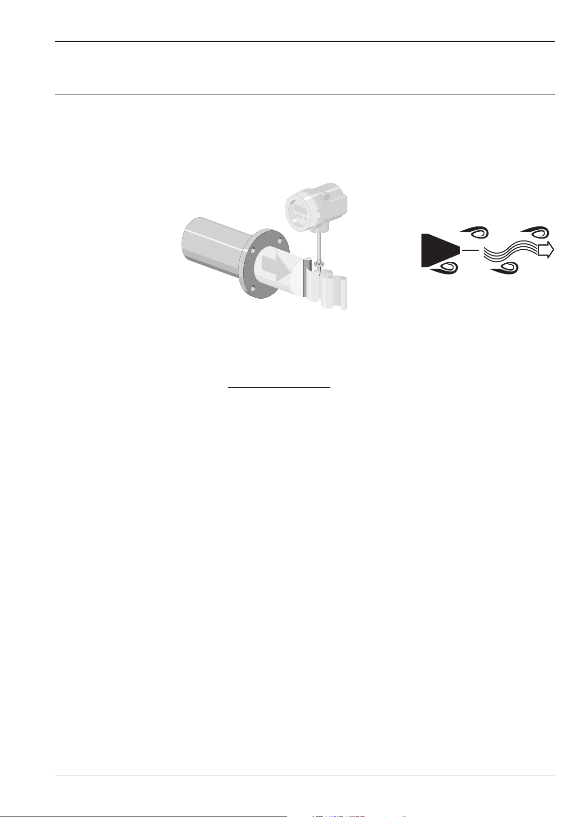
Measuring principle Vortex meters work on the principle of the Karman vortex street. When luid flows past a bluff body, vortices
are alternately formed on both sides with opposite directions of rotation. These vortices each generate a local
low pressure. The pressure fluctuations are recorded by the sensor and converted to electrical pulses.
The vortices develop very regularly within the permitted application limits of the device.
Therefore, the frequency of vortex shedding is proportional to the volume flow.
v
A0003938
The K-factor is used as the proportional constant:
K-Factor =
Pulses
Unit Volume [dm³]
A0003939-EN
Within the application limits of the device, the K-factor only depends on the geometry of the device. It is
independent of the fluid velocity and the fluid properties viscosity and density. In this way, the K-factor is also
independent of the type of matter that is to be measured, regardless of whether this is steam, gas or liquid.
The primary measuring signal is already digital (frequency signal) and linear to the flow.
After production, the K-factor is determined in the factory by means of calibration and is not subject to longtime or zero-point drift.
The device does not contain any moving parts and does not require maintenance.
Endress+Hauser 3
Page 4
Proline Prowirl 72F, 72W, 73F, 73W
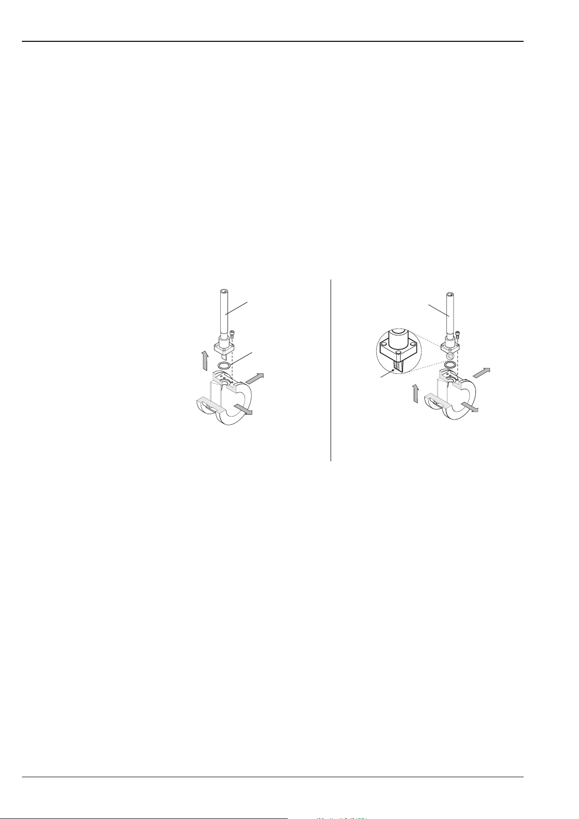
The capacitive sensor
The sensor of a vortex flowmeter has a major influence on the ability, robustness and reliability of the whole
measuring system.
The robust DSC sensor - with an integrated temperature sensor (Pt 1000) with Prowirl 73 - is burst-tested and
vibration and temperature-shock-tested (temperature shocks of 150 K/s).
The Prowirl uses the tried-and-tested capacitive measuring technology of Endress+Hauser applied in over
100,000 vortex measuring points worldwide.
The DSC sensor (Differential Switched Capacitance) patented by Endress+Hauser has complete mechanical
balancing. It only reacts to the measured variable (vortex), not to vibrations. Even in the event of pipe
vibrations, the smallest of flows can be reliably measured at low density thanks to the unimpaired sensitivity of
the sensor.
Thus, the wide turndown is also maintained even in the event of harsh operating conditions. Vibrations up to
1 g, in frequencies up to 500 Hz in every axis (X, Y, Z), do not affect the flow measurement.
Thanks to its design, the capacitive sensor is also particularly mechanically resistant to temperature shocks and
water hammer in steam lines.
Sensor
Y-Axis
X-Axis
Z-Axis
DSC sensor, Prowirl 72
Sensor
Seal
Y-Axis
Pt 1000
Z-Axis
X-Axis
A0003940-EN
DSC sensor, Prowirl 73 with integrated thermometer
(Pt 1000)
Temperature measurement (Prowirl 73)
In addition to the volume flow, the measuring device also measures the fluid temperature.
The temperature is measured by means of a Pt 1000 temperature sensor which is located in the paddle of the
DSC sensor, i.e. directly in the fluid (Fig. Pt 1000).
Flow computer (Prowirl 73)
The electronics of the measuring device have an integral flow computer. With the aid of this flow computer
other process variables can be calculated from the primary measured variables (volume flow and temperature),
e.g.:
• The mass flow and heat flow of saturated steam and water in accordance with IAPWS-IF97/ASME
• The mass flow and heat flow of superheated steam (at constant pressure or pressure read in via HART/
PROFIBUS PA/FOUNDATION Fieldbus) in accordance with IAPWS-IF97/ASME
• The mass flow and corrected volume flow of other gases (at a constant pressure or pressure read in via
HART/PROFIBUS PA/FOUNDATION Fieldbus, e.g. compressed air or optional natural gas AGA NX-19)
• The mass flow of any liquid (linear equation)
• Delta heat between saturated steam and condensate (second temperature read in via HART) in accordance
with IAPWS-IF97/ASME
• Delta heat between warm water and cold water (second temperature read in via HART) in accordance with
IAPWS-IF97/ASME
• In saturated steam measurements, the pressure of the steam can also be calculated from the measured
temperature and output in accordance with IAPWS-IF97/ASME
A0004056-EN
Diagnostic options (Prowirl 73)
Extensive diagnostic options, such as retracing fluid and ambient temperatures, extreme flows etc., are also
optionally available for the measuring device.
4 Endress+Hauser
Page 5
Proline Prowirl 72F, 72W, 73F, 73W
Measuring system The measuring system comprises a sensor and a transmitter.
Two versions are available:
• Compact version: sensor and transmitter form a mechanical unit.
• Remote version: sensor is mounted separate from the transmitter.
Sensor
• Prowirl F (flanged version)
• Prowirl W (wafer version)
Transmitter
• Prowirl 72
• Prowirl 73
Input
Measured variable Prowirl 72
• Volumetric flow (volume flow) is proportional to the frequency of vortex shedding after the bluff body.
• The volume flow or, if process conditions are constant, the mass flow or corrected volume flow can be output
as the output variables.
Prowirl 73
• Volumetric flow (volume flow) is proportional to the frequency of vortex shedding after the bluff body.
• The temperature can be output directly and is used to calculate the mass flow for example.
• The measured process variables volume flow, temperature or the calculated process variables mass flow, heat
flow or corrected volume flow can be output as the output variables.
Measuring range The measuring range depends on the fluid and the nominal diameter.
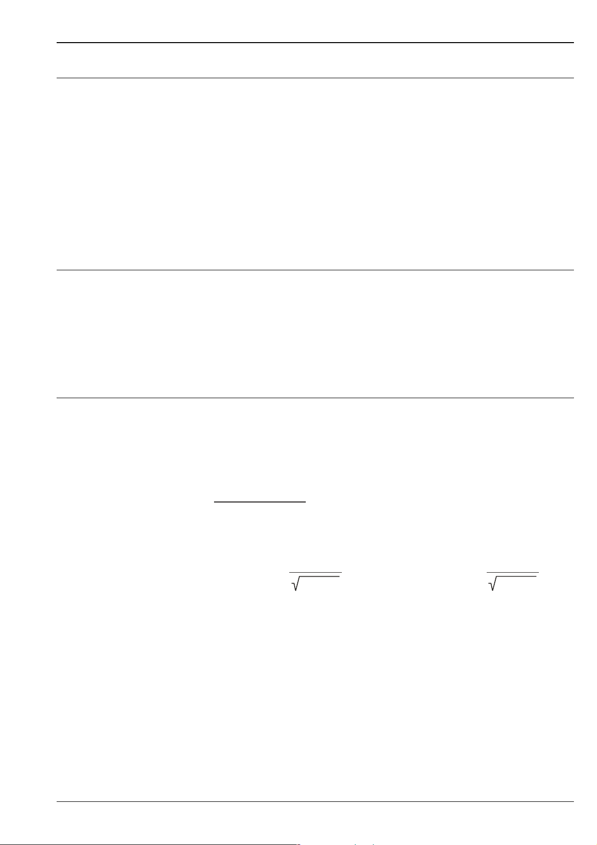
Start of measuring range
Depends on the density and the Reynolds number (Re
= 4,000, Re
min
The Reynolds number is dimensionless and is the ratio of inertial forces to viscous forces of the fluid. It is used
for characterizing the flow. The Reynolds number is calculated as follows:
4·Q · m³[m³/s] [kg/ ]
Re
=
Re = Reynolds number; Q = flow; di = internal diameter; m = dynamic viscosity, r = density
DN 15...25
di [m] · µ · [Pa·s]
v
min.
=
6
[m/s] [m/s]
DN 40...300
[kg/m³]
Full scale value
• Gas/steam: v
• Liquids: v
max
= 75 m/s (DN 15: v
max
= 9 m/s
= 46 m/s)
max
Note!
By using the selection and planning program "Applicator", you can determine the exact values for the fluid you
use. You can obtain the Applicator from your Endress+Hauser sales center or on the Internet under
www.endress.com.
= 20,000).
linear
v
=
min.
A0003794
7
[kg/m³]
A0003239
Endress+Hauser 5
Page 6
Proline Prowirl 72F, 72W, 73F, 73W
Measuring range for gases [m³/h or Nm³/h]
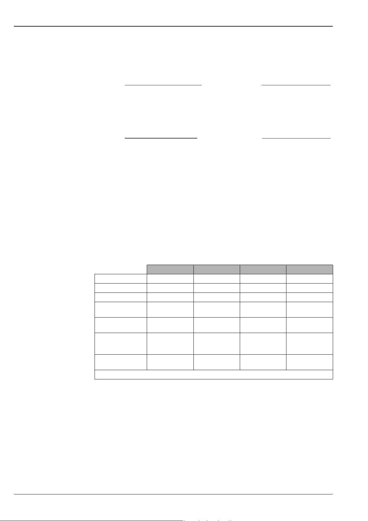
In the case of gases, the start of the measuring range depends on the density. With ideal gases, the density [ρ]
or corrected density [ρN] can be calculated using the following formulae:
[kg/Nm³] · P [bar abs] · 273.15 [K]
r
r [kg/m³] =
N
T [K] · 1.013 [bar abs]
[kg/Nm³] =
r
N
The following formulae can be used to calculate the volume [Q] or corrected volume [QN] in the case of ideal
gases:
[kg/m³] · T [K] · 1.013 [bar abs]
r
P [bar abs] · 273.15 [K]
A0003946
[Nm³/h] · T [K] · 1.013 [bar abs]Q
Q [m³/h] =
T = Operating temperature, P = operating pressure
N
P [bar abs] · 273.15 [K]
[Nm³/h] =
Q
N
[m³/h] · P [bar abs] · 273.15 [K]Q
T [K] · 1.013 [bar abs]
A0003941
Output
Prowirl 72
By means of the outputs in the 4...20mA/HART version of Prowirl 72, the volume flow and, if process
conditions are constant, the calculated mass flow and corrected volume flow can be output via the current
output and optionally via the pulse output or as a limit value via the status output.
Prowirl 73
By means of the outputs in the 4...20mA/HART version of Prowirl 73, the following measured variables can
generally be output:
Current output Frequency output Pulse output Status output
Volume flow If configured If configured If configured Limit value*
Temperature If configured If configured – Limit value
Mass flow If configured If configured If configured Limit value*
Corrected volume
flow
Heat flow
(performance)
Saturation steam
pressure (only for
saturated steam)
Operating pressure (if
read in externally)
* Limit value for flow or totalizer
If configured If configured If configured Limit value*
If configured If configured If configured Limit value*
If configured If configured If configured Limit value*
If configured If configured If configured Limit value*
If configured, the calculated measured variables density, specific enthalpy, saturation steam pressure (for
saturated steam), Z-factor and flow velocity can also be shown on the local display for Prowirl 73.
6 Endress+Hauser
Page 7

Proline Prowirl 72F, 72W, 73F, 73W
Output signal Prowirl 72
Current output:
• 4...20 mA with HART,
• Full scale value and time constant (0...100 s) can be set
Pulse/status output:
• Open collector, passive, galvanically isolated
– Non-Ex, Ex d version:
U
max
– Ex i and Ex n version:
U
max
The pulse/status output can be configured as:
• Pulse output:
– Pulse value and polarity can be selected (5...2,000 ms)
– Pulse width can be configured (0.005...2s)
– Pulse frequency max. 100 Hz
• Status output:
Can be configured for error messages or flow limit values
• Vortex frequency:
– Direct output of unscaled vortex pulses 0.5...2,850 Hz
(e.g. for connecting to an RMC 621 flow computer)
– Pulse ratio 1:1
= 36 V, with 15 mA current limiting, Ri = 500 Ω
= 30 V, with 15 mA current limiting, Ri = 500 Ω
PROFIBUS PA interface:
– PROFIBUS PA in accordance with EN 50170 Volume 2, IEC 61158-2 (MBP), galvanically isolated
– Current consumption = 16 mA
– Error current FDE (Fault Disconnection Electronic) = 0 mA
– Data transmission rate: supported baudrate = 31.25 kBit/s
– Signal encoding = Manchester II
– Function blocks: 1 x Analog Input, 1 x totalizer
– Output data: volume flow, calculated mass flow, corrected volume flow, totalizer
– Input data: positive zero return (ON/OFF), totalizer control
– Bus address can be set at the device via DIP switches
FOUNDATION Fieldbus interface:
– FOUNDATION Fieldbus H1, IEC 61158-2, galvanically isolated
– Current consumption = 16 mA
– Error current FDE (Fault Disconnection Electronic) = 0 mA
– Data transmission rate: supported baudrate = 31.25 kBit/s
– Signal encoding = Manchester II
– Function blocks: 2 x Analog Input, 1 x Discrete Output
– Output data: volume flow, calculated mass flow, corrected volume flow, totalizer
– Input data: positive zero return (ON/OFF), totalizer reset
– Link Master (LM) functionality is supported
Endress+Hauser 7
Page 8

Proline Prowirl 72F, 72W, 73F, 73W
Prowirl 73
Current output:
• 4...20 mA with HART,
• Full scale value and time constant (0...100 s) can be set
Frequency output, pulse/status output:
• Frequency output (optional): open collector, passive, galvanically isolated
– Non-Ex, Ex d version:
= 36 V, with 15 mA current limiting, Ri = 500 Ω
U
max
– Ex i and Ex n version:
U
= 30 V, with 15 mA current limiting, Ri = 500 Ω
max
The pulse/status output can be configured as:
• Frequency output:
– End frequency 0...1,000 Hz (fmax = 1,250 Hz)
• Pulse output:
– Pulse value and polarity can be selected (5...2,000 ms)
– Pulse width can be configured (0.005...2s)
– Pulse frequency max. 100 Hz
• Status output:
Can be configured for error messages or flow values, temperature values, pressure limit values
• Vortex frequency:
– Direct output of unscaled vortex pulses 0.5...2,850 Hz
(e.g. for connecting to an RMC 621 flow computer)
– Pulse ratio 1:1
PROFIBUS PA interface:
– PROFIBUS PA in accordance with EN 50170 Volume 2, IEC 61158-2 (MBP), galvanically isolated
– Current consumption = 16 mA
– Error current FDE (Fault Disconnection Electronic) = 0 mA
– Data transmission rate: supported baudrate = 31.25 kBit/s
– Signal encoding = Manchester II
– Function blocks: 4 x Analog Input, 2 x totalizer
– Output data: volume flow, mass flow, corrected volume flow, heat flow, temperature, density, specific
enthalpy, calculated steam pressure (saturated steam), operating Z-factor, vortex frequency, electronics
temperature, Reynolds number, velocity, totalizer
– Input data: positive zero return (ON/OFF), totalizer control, pressure, display value
– Bus address can be set at the device via DIP switches
FOUNDATION Fieldbus interface:
– FOUNDATION Fieldbus H1, IEC 61158-2, galvanically isolated
– Current consumption = 16 mA
– Error current FDE (Fault Disconnection Electronic) = 0 mA
– Data transmission rate: supported baudrate = 31.25 kBit/s
– Signal encoding = Manchester II
– Function blocks: 6 x Analog Input, 1 x Discrete Output, 1 x Analog Output
– Output data: volume flow, mass flow, corrected volume flow, heat flow, temperature, density, specific
enthalpy, calculated steam pressure (saturated steam), operating Z-factor, vortex frequency, electronics
temperature, Reynolds number, velocity, totalizer 1 + 2
– Input data: positive zero return (ON/OFF), totalizer reset, pressure
– Link Master (LM) functionality is supported
8 Endress+Hauser
Page 9
Proline Prowirl 72F, 72W, 73F, 73W
[] []
Signal on alarm • Current output: error response can be selected (e.g. in accordance with NAMUR Recommendation NE 43)
• Pulse output: error response can be selected
• Status output: "not conducting" in event of fault (open circuit)
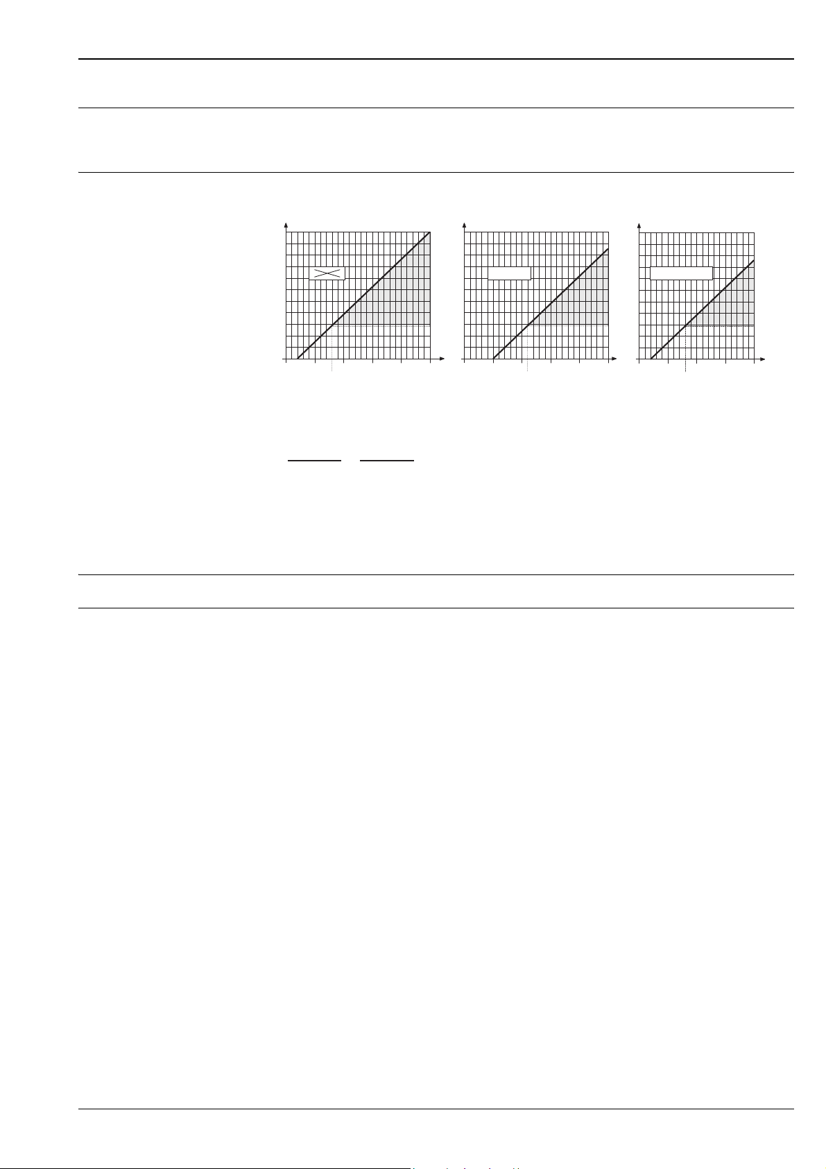
Load
W
RR
BB
1100 1100
1000 1000
900 900
800 800
700 700
600 600
500 500
400 400
300 300
200 200
100 100
00
Ex
10 1020 2025 2530 3036 3615 15
18
W
Ex d
21
The area shaded gray refers to the permitted load (for HART: min. 250 Ω)
The load is calculated as follows:
–U )
(U
RB=
R
U
U
I
SKl
-3
–10 0.022
(I )
max
Load, load resistance
B
Supply voltage: non-Ex = 12...36 V DC; Ex d = 15...36 V DC; Ex i and Ex n = 12...30 V DC
S
Terminal voltage: non-Ex = min. 12 V DC; Ex d = min. 15 V DC; Ex i and Ex n = min. 12 V DC
Kl
Output current (22.6 mA)
max
=
–U )
(U
SKl
Low flow cut off Switch points for low flow cut off can be selected as required
1100
1000
900
800
700
600
500
400
300
200
100
[]
W
R
B
0
10
Ex i
Ex i und Ex n
15
20 25 30
18
U
S
A0001921
[]
V
Galvanic isolation All electrical connections are galvanically isolated from one another.
Endress+Hauser 9
Page 10
Electrical connection
Proline Prowirl 72F, 72W, 73F, 73W
Power supply
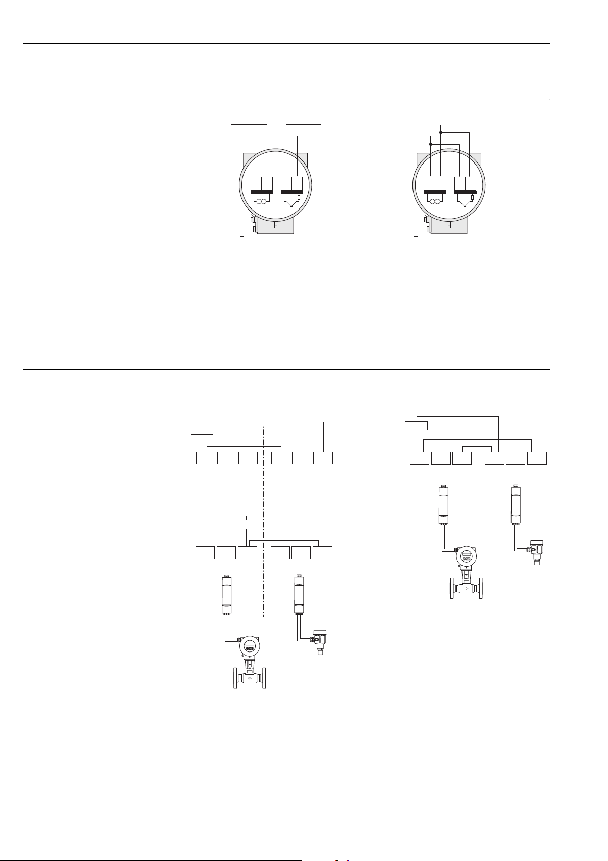
Wiring when using the HART input
A
----
++++
B
D
12 1234 34
C
A – HART: power supply, current output
– PROFIBUS PA: 1 = PA+, 2 = PA–
– FOUNDATION Fieldbus: 1 = FF+, 2 = FF–
B Optional frequency output (not for PROFIBUS PA and FOUNDATION Fieldbus), can also be operated as:
- Pulse or status output
- Only Prowirl 73: as a PFM output (pulse/frequency modulation) together with an RMC or RMS 621 flow computer
C Ground terminal (relevant for remote version)
D Only Prowirl 72: PFM (pulse-frequency modulation) wiring
C
Process for reading in pressure, temperature or density with Prowirl 73:
PLC+ PLC (73) in PLC (p/T) in
250
A
0+
0+H
0–
0+ 0+H
0–
250
C
0+
0–
0+H
0+ 0+H
A0003392
0–
PLC–PLC (73) in PLC (p/T) in
B
0+
A Process control system with common “plus”
B Process control system with common “minus”
C Connection diagram without process control system
a Prowirl 73
b Cerabar-M or other HART-enabled and burst-enabled pressure, temperature or density transmitter
c Active barrier preline RN221N
250
0–
0+H
c
a
0+ 0+H
c
0–
b
c
a
c
b
A0004215
10 Endress+Hauser
Page 11
Proline Prowirl 72F, 72W, 73F, 73W
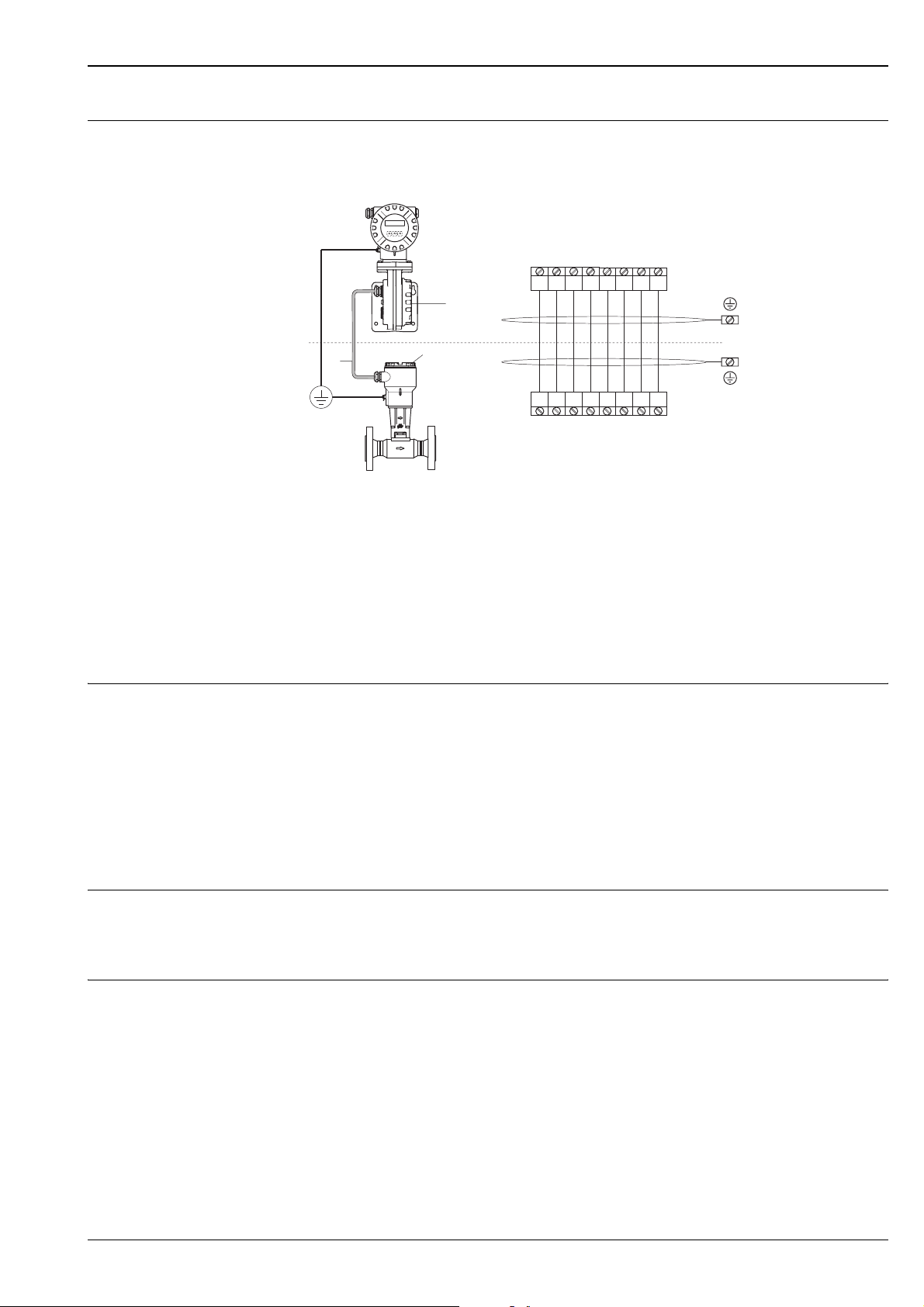
Wiring (remote version) Note!
• The remote version must be grounded. In doing so, the sensor and transmitter must be connected to the
same potential matching system.
d
Connecting the remote version
a = Connection compartment cover (transmitter)
b = Connection compartment cover (sensor)
c = Connecting cable (signal cable)
d = Identical potential matching for sensor and transmitter
e = Connect shielding to ground terminal in transmitter housing and keep as short as possible
f = Connect shielding to ground terminal in connection housing
Wire colors (colour code according to DIN 47100):
Terminal number: 1 = white; 2 = brown; 3 = green; 4 = yellow, 5 = gray; 6 = pink; 7 = blue; 8 = red
Supply voltage HART:
• Non-Ex: 12...36 V DC (18...36 V DC)
• Ex i and Ex n: 12...30 V DC (18...30 V DC)
• Ex d: 15...36 V DC (21...36 V DC)
+5VA
GROUND
3
4
3
4
+5VA
GROUND
–5VA
55667
–5VA
DIFF –
DIFF +
2
1
a
c
b
2
1
DIFF –
DIFF +
TEMP 3
TEMP 2
TEMP 1
8
e
f
7
8
TEMP 1
TEMP 3
TEMP 2
A0001893
PROFIBUS PA and FOUNDATION Fieldbus:
• Non-Ex: 9...32 V DC
• Ex i and Ex n: 9...24 V DC
• Ex d: 9...32 V DC
• Current consumption → PROFIBUS PA: 16 mA, FOUNDATION Fieldbus: 16 mA
Cable entry Power supply and signal cables (outputs):
• Cable entry M20 x 1.5 (8...11.5 mm)
• Thread for cable entry: ½" NPT, G ½", G ½" Shimada
• Fieldbus connector
Power supply failure • Totalizer stops at the last value determined (can be configured)
• All settings are kept in the EEPROM
• Error messages (incl. value of operated hours counter) are stored
Endress+Hauser 11
Page 12

Performance characteristics
Proline Prowirl 72F, 72W, 73F, 73W
Reference operating conditions
Maximum measured error Prowirl 72
Error limits following ISO/DIN 11631:
20...30 °C, 2...4 bar, calibration rig traceable to national calibration standards
Calibration with the process connection corresponding to the standard in question
• Liquid:
< 0.75% o.r. for Re > 20,000
< 0.75% o.f.s for Re between 4,000...20,000
•Gas/steam:
< 1% o.r. for Re > 20,000
< 1% o.f.s for Re between 4,000...20,000
o.r. = of reading, o.f.s = of full scale value, Re = Reynolds number
Prowirl 73
• Liquid (volume flow):
< 0.75% o.r. for Re > 20,000
< 0.75% o.f.s for Re between 4,000...20,000
• Gas/steam (volume flow):
< 1% o.r. for Re > 20,000
< 1% o.f.s for Re between 4,000...20,000
• Temperature:
< 1 °C (T > 100 °C, saturated steam);
rise time 50% (agitated under water, following IEC 60751): 8 s
• Mass flow (saturated steam):
– For flow velocities 20...50 m/s, T > 150 °C (423 K)
< 1.7% o.r. (2% o.r. for remote version) for Re > 20,000
< 1.7% o.f.s (2% o.f.s for remote version) for Re between 4,000...20,000
– For flow velocities 10...70 m/s, T > 140 °C (413 K)
< 2% o.r. (2.3% o.r. for remote version) for Re > 20,000
< 2% o.f.s (2.3% o.f.s for remote version) for Re between 4,000...20,000
• Mass flow (other media):
– depending on the pressure value specified in the instrument functions and the chosen fluid
– individual error observation must be carried out
o.r. = of reading, o.f.s = of full scale value, Re = Reynolds number
Repeatability ±0.25% o.r. (of reading)
Reaction time/step response time
Influence of ambiente temperature
If all the configurable functions for filter times (flow damping, display damping, current output time constant,
frequency output time constant, status output time constant) are set to 0, a reaction time/step response time
of 200 ms must be reckoned with for vortex frequencies as of 10 Hz.
For other settings, a reaction time/step response time of 100 ms must always be added to the total filter
reaction time for vortex frequencies as of 10 Hz.
Current output (additional error, in reference to the span of 16 mA):
• Zero point (4 mA):
average Tk: 0.05%/10 K, max. 0.6% over the entire temperature range –40 °C ... +80 °C
• Span (20 mA):
average Tk: 0.05%/10 K, max. 0.6% over the entire temperature range –40 °C ... +80 °C
Digital outputs (pulse output, PFM, HART, frequency output (Prowirl 73 only))
Due to the digital measuring signal (vortex pulse) and further digital processing, there is no interface-related
error from changing ambient temperature.
12 Endress+Hauser
Page 13
Proline Prowirl 72F, 72W, 73F, 73W
Operating conditions: installation
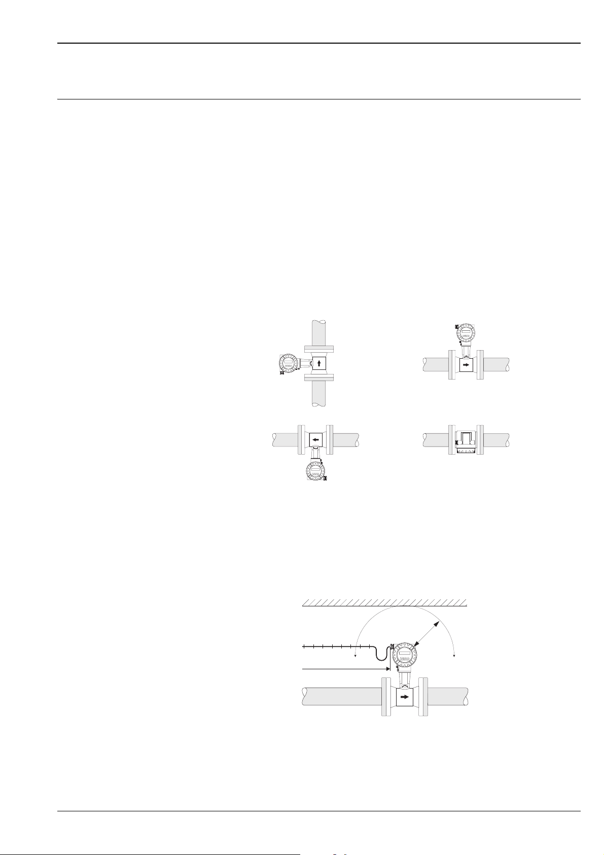
Installation instructions Vortex meters require a fully developed flow profile as a prerequisite for correct volume flow measurement.
For this reason, please note the following points when installing the device:
Orientation
The device can generally be installed in any position in the piping.
In the case of liquids, there should be upward flow in vertical pipes to avoid partial pipe filling (see orientation
A).
In the case of hot media (e.g. steam or fluid temperature ≥ 200 °C), select orientation C or D so that the
permitted ambient temperature of the electronics is not exceeded. Orientations B and D are recommended for
very cold media (e.g. liquid nitrogen).
Orientations B, C and D are possible with horizontal installation.
The arrow indicated on the device must always point in the direction of flow in all orientations.
Caution!
• If fluid temperature is ≥ 200 °C, orientation B is not permitted for the wafer version
(Prowirl 72W, 73W) with a nominal diameter of DN 100 and DN 150.
• To guarantee the flow measurement of liquids, the measuring tube must always be completely full in pipes
with vertical downward flow.
A
C
Minimum spacing and cable length
To ensure problem-free access to the measuring device for service purposes, we recommend you observe the
following dimensions:
• Minimum spacing in all directions = 100 mm (A)
• Necessary cable length L + 150 mm
B
D
A0001869
A
L
A0001870
Rotating the electronics housing and the display
The electronics housing can be rotated continuously 360 ° on the housing support. The display unit can be
rotated in 45 ° stages. This means you can read off the display comfortably in all orientations.
Endress+Hauser 13
Page 14
Proline Prowirl 72F, 72W, 73F, 73W
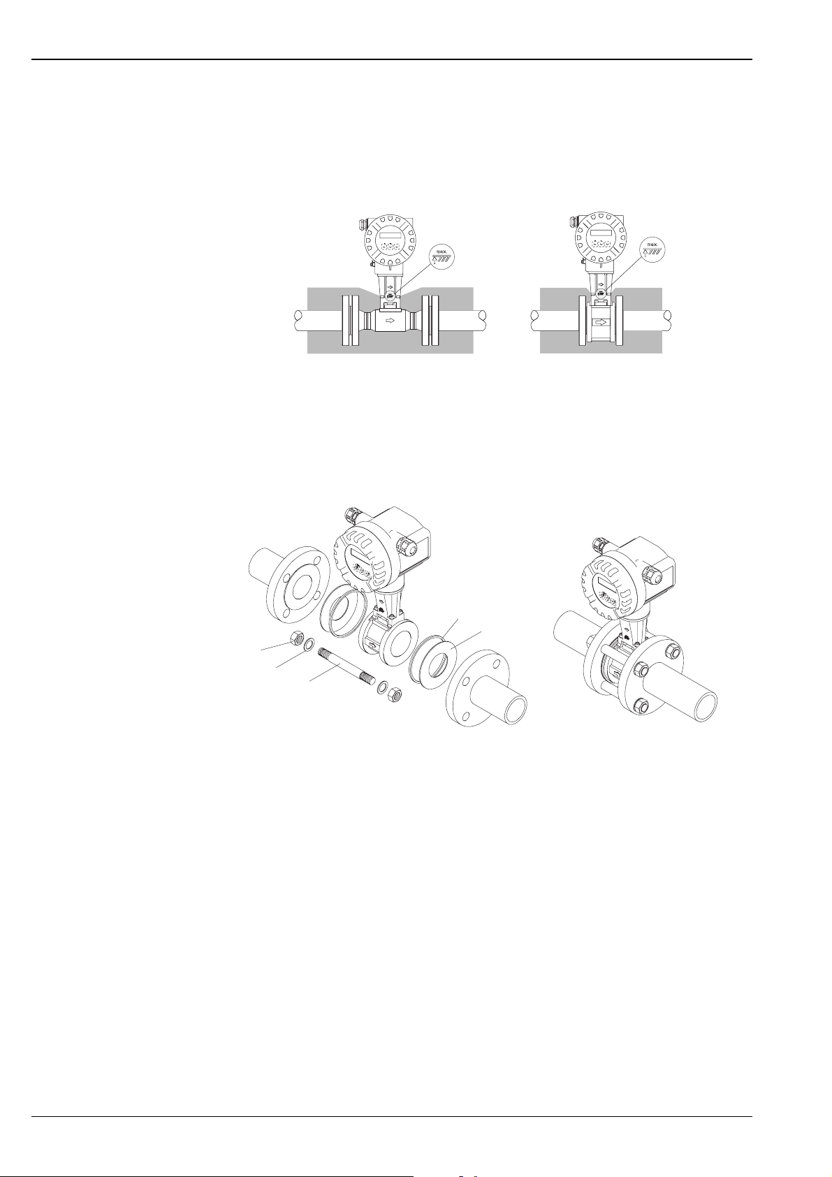
Piping insulation
When insulating, please ensure that a sufficiently large area of the housing support is exposed.
The uncovered part serves as a radiator and protects the electronics from overheating (or undercooling).
The maximum insulation height permitted is illustrated in the diagrams. These apply equally to both the
compact version and the sensor in the remote version.
12
Esc
-
+
E
Esc
-
+
E
A0001868
1 = Flanged version
2 = Wafer version
Wafer version mounting set
The centering rings supplied are used to mount and center the wafer-style devices. A mounting set consisting
of tie rods, seals, nuts and washers can be ordered separately.
4
5
1
2
3
A0001888
Mounting wafer version
1 = Nut
2 = Washer
3 = Tie rod
4 = Centering ring (is supplied with the device)
5 = Seal
14 Endress+Hauser
Page 15
Proline Prowirl 72F, 72W, 73F, 73W
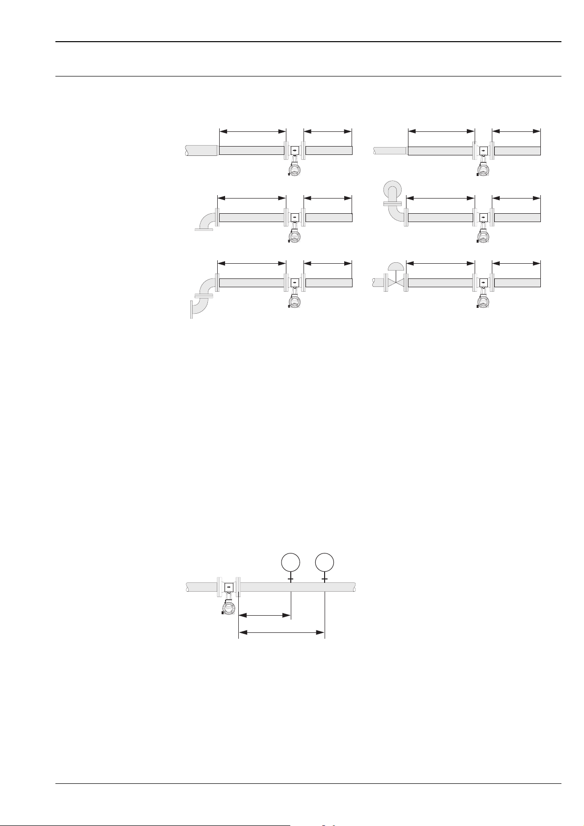
Inlet and outlet run As a minimum, the inlet and outlet runs shown below must be observed to achieve the specified accuracy of
the device. The longest inlet run shown must be observed if two or more flow disturbances are present.
1
3
5
15xDN 5xDN
A
20 x DN
A
25xDN
A
Esc
-
+
Esc
-
+
Esc
-
+
B
E
5xDN
B
E
5xDN
B
E
Minimum inlet and outlet runs with various flow obstructions
A = Inlet run
B = Outlet run
1 = Reduction
2 = Extension
3 = 90° elbow or T-piece
4 = 2 x 90° elbow, -dimensional
5 = 2 x 90° elbow
6 = Control valve
2
4
18xDN 5xDN
A
Esc
-
+
E
B
40 x DN 5 x DN
A
Esc
-
+
E
6
50 x DN
A
Esc
-
+
E
B
5xDN
B
A0001867
Note!
A specially designed perforated plate flow conditioner can be installed if it is not possible to observe the inlet
runs required (→ Page 16).
Outlet runs with pressure and temperature measuring points
If pressure and temperature measuring points are installed after the device, please ensure there is a large
enough distance between the device and the measuring point so there are no negative effects on vortex
formation in the sensor.
Esc
-
+
E
PT
3...5 x DN
TT
4...8 x DN
A0003780
PT = Pressure measuring point
TT = Temperature measuring point
Endress+Hauser 15
Page 16
Proline Prowirl 72F, 72W, 73F, 73W
Perforated plate flow conditioner
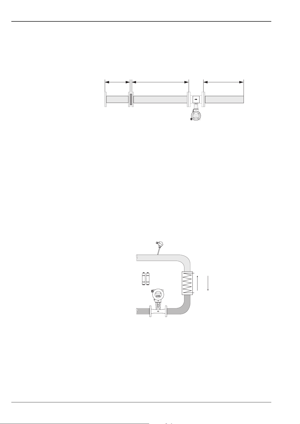
A specially designed perforated plate flow conditioner, available from Endress+Hauser, can be installed if it is
not possible to observe the inlet runs required.
The flow conditioner is fitted between two piping flanges and centered with the mounting bolts. Generally,
this reduces the inlet run required to 10 x DN with complete accuracy.
2xDN
8xDN
5xDN
A0001887
The pressure loss for flow conditioners is calculated as follows:
∆p [mbar] = 0.0085 · ρ [kg/m³] · v² [m/s]
Examples of pressure loss for flow conditioner
•Example with steam
p = 10 bar abs
t = 240 °C → ρ = 4.39 kg/m³
v = 40 m/s
∆p = 0.0085 · 4.39 · 40² = 59.7 mbar
• Example with H
ρ = 965 kg/m³
v = 2.5 m/s
∆p = 0.0085 · 965 · 2.5² = 51.3 mbar
condensate (80°C)
2O
Installation of delta heat measurement (Prowirl 73 HART)
• The second temperature measurement takes place by means of a separate sensor and is read in via HART.
• Prowirl 73 generally has to be installed on the steam side for saturated steam delta heat measurement.
• For water-delta heat measurement, Prowirl 73 can be installed on both the cold side and the warm side.
• The inlet and outlet runs specified above must be observed.
12
A0001809
Layout for delta heat measurement of saturated steam and water
16 Endress+Hauser
Page 17

Proline Prowirl 72F, 72W, 73F, 73W
Operating conditions: environment
Ambient temperature range • Compact version: –40...+70 °C
(EEx-d version: –40...+60 °C; ATEX II 1/2 GD version/dust ignition-proof: –20...+55 °C)
Display can be read between –20 °C...+70 °C
• Remote version:
Sensor –40...+85 °C
(ATEX II 1/2 GD version/dust ignition-proof: –20...+55 °C)
Transmitter –40...+80 °C
(EEx-d version: –40...+60 °C; ATEX II 1/2 GD version/dust ignition-proof: –20...+55 °C)
Display can be read between –20 °C...+70 °C
When mounting outside, protect from direct sunlight with a protective cover (order number 543199),
especially in warmer climates with high ambient temperatures.
Storage temperature –40...+80 °C (ATEX II 1/2 GD version/dust ignition-proof: –20...+55°C)
Degree of protection IP 67 (NEMA 4X) in accordance with EN 60529
Vibration resistance Acceleration up to 1 g, 10...500 Hz, following IEC 60068-2-6
Electromagnetic compatibility (EMC)
To EN 61326/A1 and NAMUR Recommendation NE 21
Operating conditions: process
Fluid temperature range Prowirl 72
DSC standard sensor –40...+260 °C
DSC high/low temperature sensor –200...+400 °C
DSC sensor Inconel
(PN 63...160, Class 600, JIS 40K and Dualsens version)
DSC sensor titanium Gr. 5
(PN 250, Class 900…1500 and butt-weld version)
DSC sensor Alloy C-22 –200...+400 °C
•Seal:
Graphite –200...+400 °C
Viton –15...+175 °C
Kalrez –20...+275 °C
Gylon (PTFE) –200...+260 °C
–200...+400 °C
–50…+400 °C
Prowirl 73
DSC standard sensor –200...+400 °C
DSC sensor Inconel
(PN 63...160, Class 600, JIS 40K and Dualsens version in
development)
•Seal:
Graphite –200...+400 °C
Viton –15...+175 °C
Kalrez –20...+275 °C
Gylon (PTFE) –200...+260 °C
–200...+400 °C
Endress+Hauser 17
Page 18
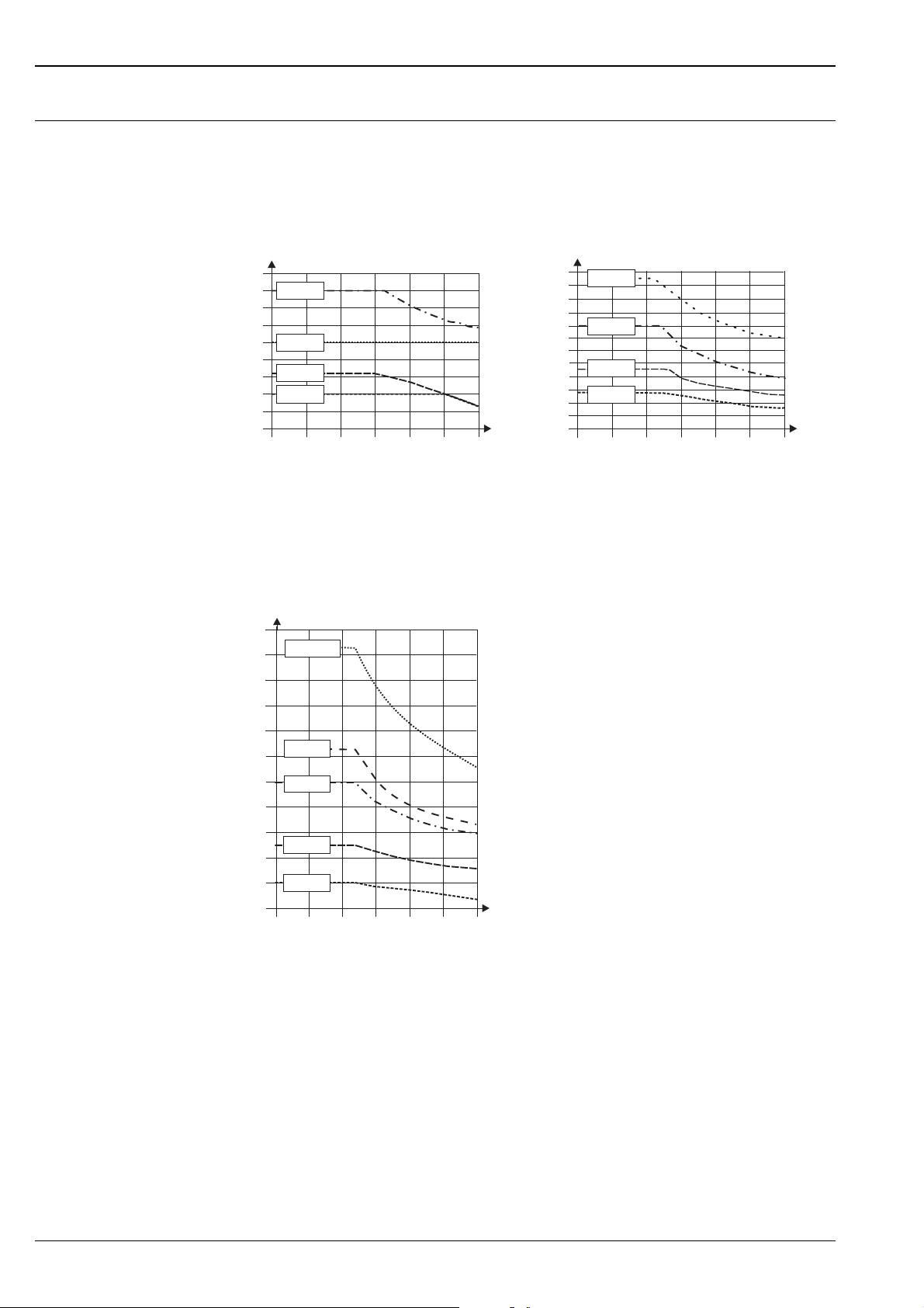
Fluid pressure Prowirl 72
Pressure-temperature curve to EN (DIN), stainless steel
PN 10...40 → Prowirl 72W and 72F
PN 63...250 → Prowirl 72F
Proline Prowirl 72F, 72W, 73F, 73W
bar
45
40
35
30
25
20
15
10
5
0
-200 -100
PN 40
PN 25
PN 16
PN 10
PN 10...40
0 100 200 300 400
°C
260
240
200
180
160
140
120
100
Pressure-temperature curve to ANSI B16.5, stainless steel
ANSI B16.5:
Class 150...300 → Prowirl 72W and 72F
Class 600...1500 → Prowirl 72F
bar
220
200
180
Class 150...1500
Cl. 1500
bar
80
60
40
20
0
-200 -100
PN 250
PN 160
PN 100
PN 63
PN 63...250
0 100 200 300 400
°C
A0003238
160
140
120
100
80
60
40
20
0
-200 -100
Cl. 900
Cl. 600
Cl. 300
Cl. 150
°C
0 100 200 300 400
A0003402
18 Endress+Hauser
Page 19
Proline Prowirl 72F, 72W, 73F, 73W
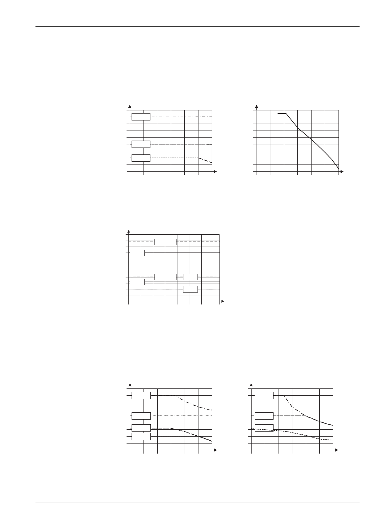
Pressure-temperature curve to JIS B2238 and butt-weld version, stainless steel:
• JIS B2238:
10...20K → Prowirl 72W and 72F
40K → Prowirl 72F
• Butt-weld version:
PN250, Cl 1500 → Prowirl 72F
bar
45
40
35
30
25
20
15
10
5
0
-200 -100
40 K
20 K
10 K
JIS10...40 K
0 100 200 300 400
°C
bar
260
250
240
230
220
210
200
190
180
170
-200 -100
PN 250, Cl. 1500
0 100 200 300 400
Pressure-temperature curve to EN (DIN), ANSI B16.5 and JIS B2238, Alloy C-22
PN 16...40, Class 150...300, 10...20K → Prowirl 72F
bar
55
50
45
40
35
30
25
20
15
10
5
0
PN 40
PN 16
-40 0
Class 300
Class 150
40 80 120 160 200 260
20 K
10 K
°C
°C
A0003404
A0003395
Prowirl 73
Pressure-temperature curve to EN (DIN), stainless steel
PN 10...40 → Prowirl 73W and 73F
PN 63...160 → Prowirl 73F (in development)
PN 160PN 40
PN 100
PN 63
PN 63...160
0 100 200 300 400
°C
A0001922
bar
45
40
35
30
25
20
15
10
5
0
-200 -100
PN 25
PN 16
PN 10
PN 10...40
0 100 200 300 400
°C
bar
180
160
140
120
100
80
60
40
20
0
-200 -100
Endress+Hauser 19
Page 20
Proline Prowirl 72F, 72W, 73F, 73W
)*
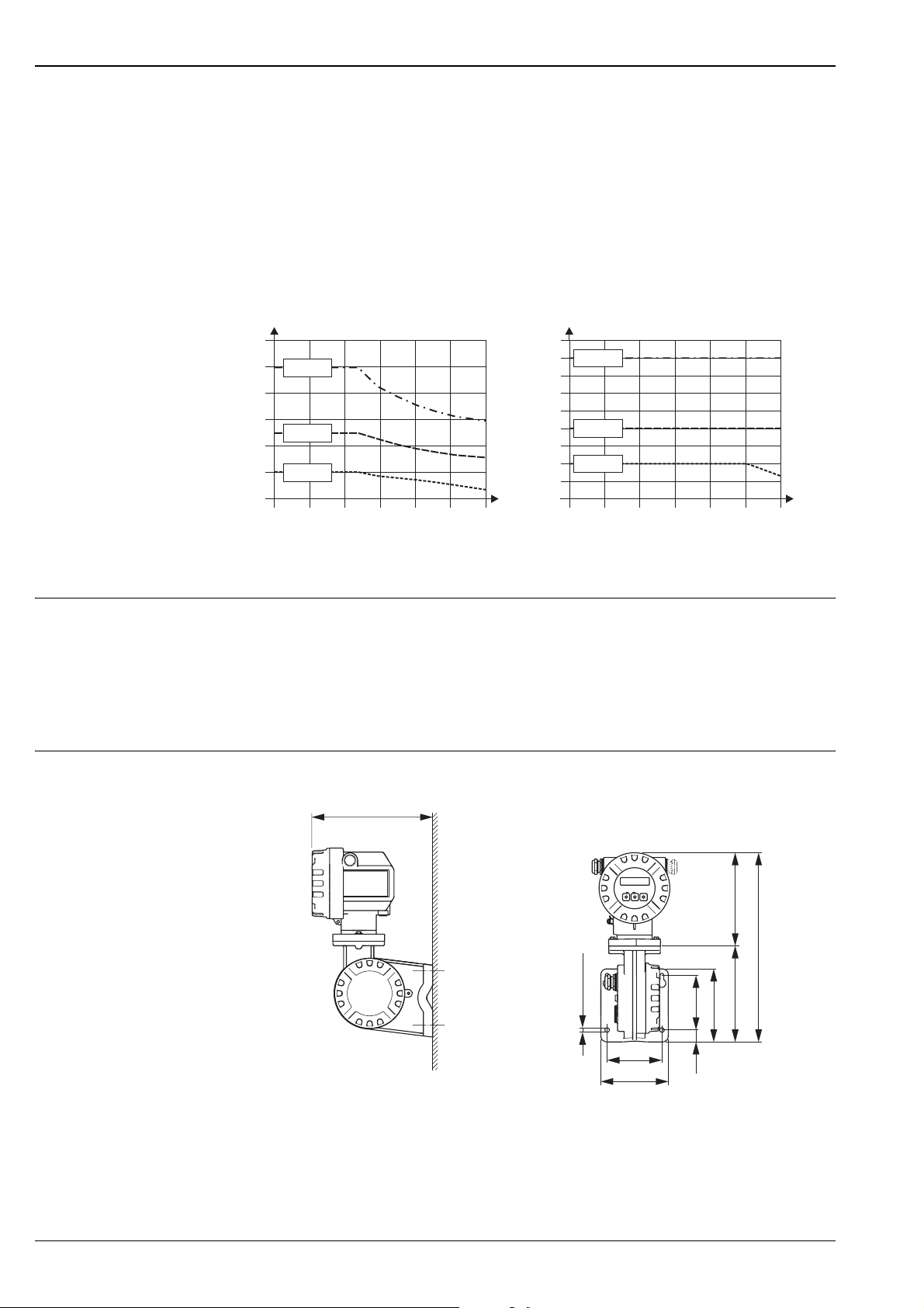
Pressure-temperature curve to ANSI B16.5 and JIS B2238, stainless steel
ANSI B 16.5:
Class 150...300 → Prowirl 73W and 73F
Class 600 → Prowirl 73F (in development)
JIS B2238
10...20 K → Prowirl 73W and 73F
40 K → Prowirl 73F (in development)
bar
120
100
80
60
40
20
0
-200 -100
Class 150...600
Cl. 600
Cl. 300
Cl. 150
0 100 200 300 400
°C
bar
45
40
35
30
25
20
15
10
5
0
-200 -100
40 K
20 K
10 K
10...40 K
°C
0 100 200 300 400
A0001923
Pressure loss The pressure loss can be determined with the aid of Applicator. Applicator is software for selecting and planning
flowmeters. The software is available both via the Internet (www.applicator.com) and on a CD-ROM for local
PC installation.
Mechanical construction
Design, dimensions Dimensions of transmitter, remote version
232(226
* The following dimensions differ depending on the version:
– The dimension 232 mm changes to 226 mm in the blind version (without local operation).
– The dimension 170 mm changes to 183 mm in the Ex d version.
– The dimension 340 mm changes to 353 mm in the Ex d version.
Ø 8.6 (M8)
Esc
-
100
123
+
E
170 (183)*
340 (353)*
170
100
144
23
A0003594
20 Endress+Hauser
Page 21
Proline Prowirl 72F, 72W, 73F, 73W
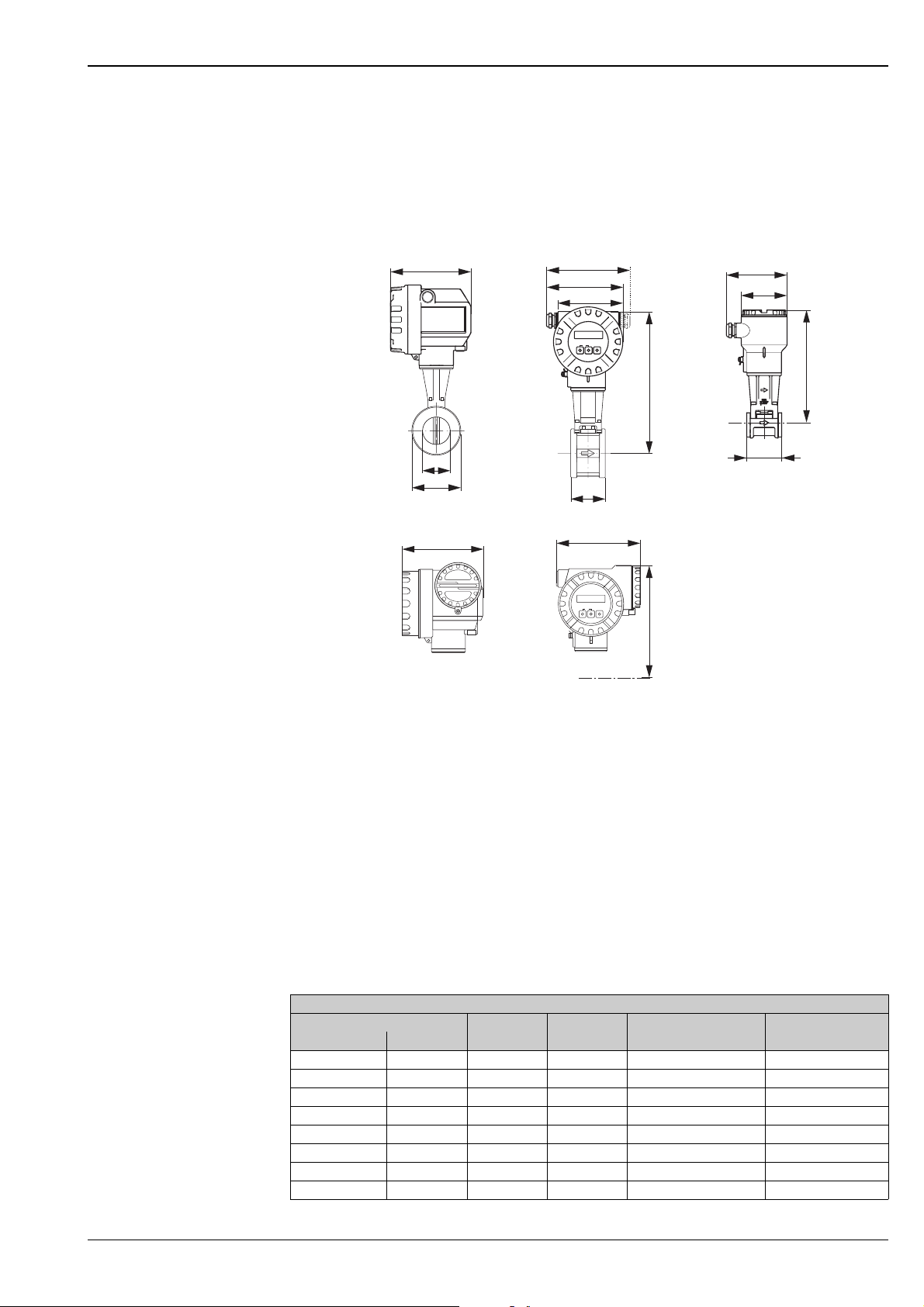
Dimensions of Prowirl 72W, 73 W
Wafer version for flanges to:
• EN 1092-1 (DIN 2501), PN 10...40
• ANSI B16.5, Class 150...300, Sch. 40
• JIS B2238, 10...20 K, Sch. 40
A
149 (142)*
161...181**
141...151**
121
Esc
-
+
E
H
B
105
95
H–42.5
H
d
D
C
151 (144)*
A
N
P
N
S
U
R
N
E
T
N
S
O
R
I
U
R
U
S
V
T
U
O
H
S
C
I
A
P
WARNUNG
N
E
N
AVERTISSEMENT
WARNING
T
I
U
A
L
I
V
E
C
R
I
E
C
H
R
N
T
W
E
H
E
H
P
S
O
I
V
M
E
A
T
G
Ö
F
F
T
N
E
N
E
S
N
I
O
N
K
E
E
P
IN
T
I
G
E
X
P
L
O
S
65
-
Esc
161
+
E
65
H+7
A = Standard as well as Ex i and Ex n version
B = Remote version
C = Ex d version (transmitter)
* The following dimensions change as follows in the blind version (without local operation):
– Standard as well as Ex i and Ex n version: the dimension 149 mm changes to 142 mm in the blind version.
– Ex d version: the dimension 151 mm changes to 144 mm in the blind version.
** The dimension depends on the cable gland used.
A0003596
Note!
• In the following tables, dimension H increases by 29 mm for Prowirl 72 (high-temperature version and for
the version with a DSC sensor made of Alloy C-22) and for Prowirl 73 (version with extended temperature
range).
• The weight data refer to the compact version. The weight increases by 0.5 kg for Prowirl 72 (hightemperature version and for the version with a DSC sensor made of Alloy C-22 and for Prowirl 73 (version
with extended temperature range).
Prowirl 72W, 73W
DN d D H Weight
DIN/JIS ANSI [mm] [mm] [mm] [kg]
15 ½" 16.50 45.0 247 3.0
25 1" 27.60 64.0 257 3.2
40 1½" 42.00 82.0 265 3.8
50 2" 53.50 92.0 272 4.1
80 3" 80.25 127.0 286 5.5
100 (DIN only) – 104.75 157.2 299 6.5
100 (JIS only) 4" 102.3 157.2 299 6.5
150 6" 156.75 215.9 325 9.0
Endress+Hauser 21
Page 22
Proline Prowirl 72F, 72W, 73F, 73W
Esc
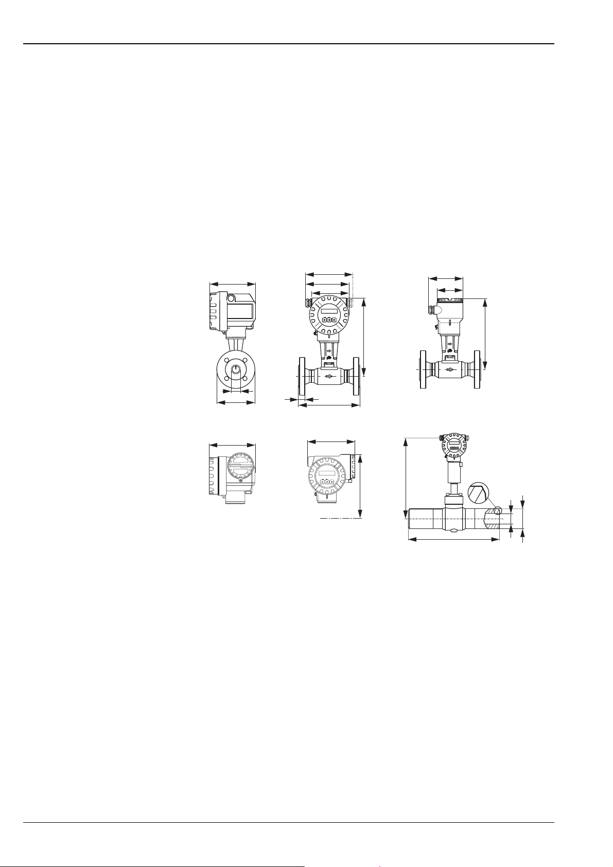
Dimensions of Prowirl 72F, 73F
Flanged version to:
• EN 1092-1 (DIN 2501), Ra = 6.3...12.5 mm
• Raised face to:
– EN 1092-1 Form B1 (DIN 2526 Form C), PN 10...40, Ra = 6.3...12.5 mm,
optional with groove to EN1091-1 Form D (DIN 2512 Form N)
– EN 1092-1 Form B2 (DIN 2526 Form E), PN 63...100, Ra = 1.6...3.2 mm
– DIN 2526 Form E, PN 160...2503), Ra = 1.6...3.2 mm
• ANSI B16.5, Class 150...15001) 2), Ra = 125...250 min2)
• JIS B2238, 10...40K1), Ra = 125...250 min
1)
Prowirl 73F: PN63...160, Cl 600 and 40K in development
2)
Prowirl 73F: only Class 150...600
3) Prowirl 73F: only PN 160
1)
1) 2)
A
149 (142)*
141...151**
161...181**
B
121
Esc
-
+
E
105
95
H
d
D
C
151 (144)*
N
A
P
N
S
U
N
R
E
G
T
Ö
N
S
O
R
I
U
F
R
U
S
F
V
T
U
T
N
O
E
H
N
E
S
C
S
N
I
A
I
P
WARNUNG
N
O
N
E
N
AVERTISSEMENT
WARNING
K
T
E
I
E
U
A
I
L
V
E
P
C
IN
T
R
I
E
I
G
C
E
H
R
N
T
W
E
H
X
E
P
H
L
P
O
S
S
O
I
V
M
E
A
T
X
-
161
Esc
L
D
Esc
-
+
E
+
E
H
H+7
L
A = Standard, Ex i and Ex n version
B = Remote version
C = Ex d version (transmitter)
D = Butt-weld version (only available for Prowirl 72)
* The following dimensions change as follows in the blind version (without local operation):
– Standard, Ex i and Ex n version: the dimension 149 mm changes to 142 mm in the blind version.
– Ex d version: the dimension 151 mm changes to 144 mm in the blind version.
** The dimension depends on the cable gland used.
m Groove type 22 in accordance with DIN 2559
H–42
m
d
D
A0003537
Note!
• In the following tables, dimension H increases by 29 mm for Prowirl 72 (high-temperature version and for
the version with a DSC sensor made of Alloy C-22) and for Prowirl 73 (pressure ratings up to
PN 40, Cl. 300, 20K).
• The weight data refer to the compact version. The weight increases by
0.5 kg for Prowirl 72 (high-temperature version and for the version with a DSC sensor made of Alloy C-22
and for Prowirl 73 (pressure rating up to PN 40, Cl. 300, 20K).
22 Endress+Hauser
Page 23
Proline Prowirl 72F, 72W, 73F, 73W
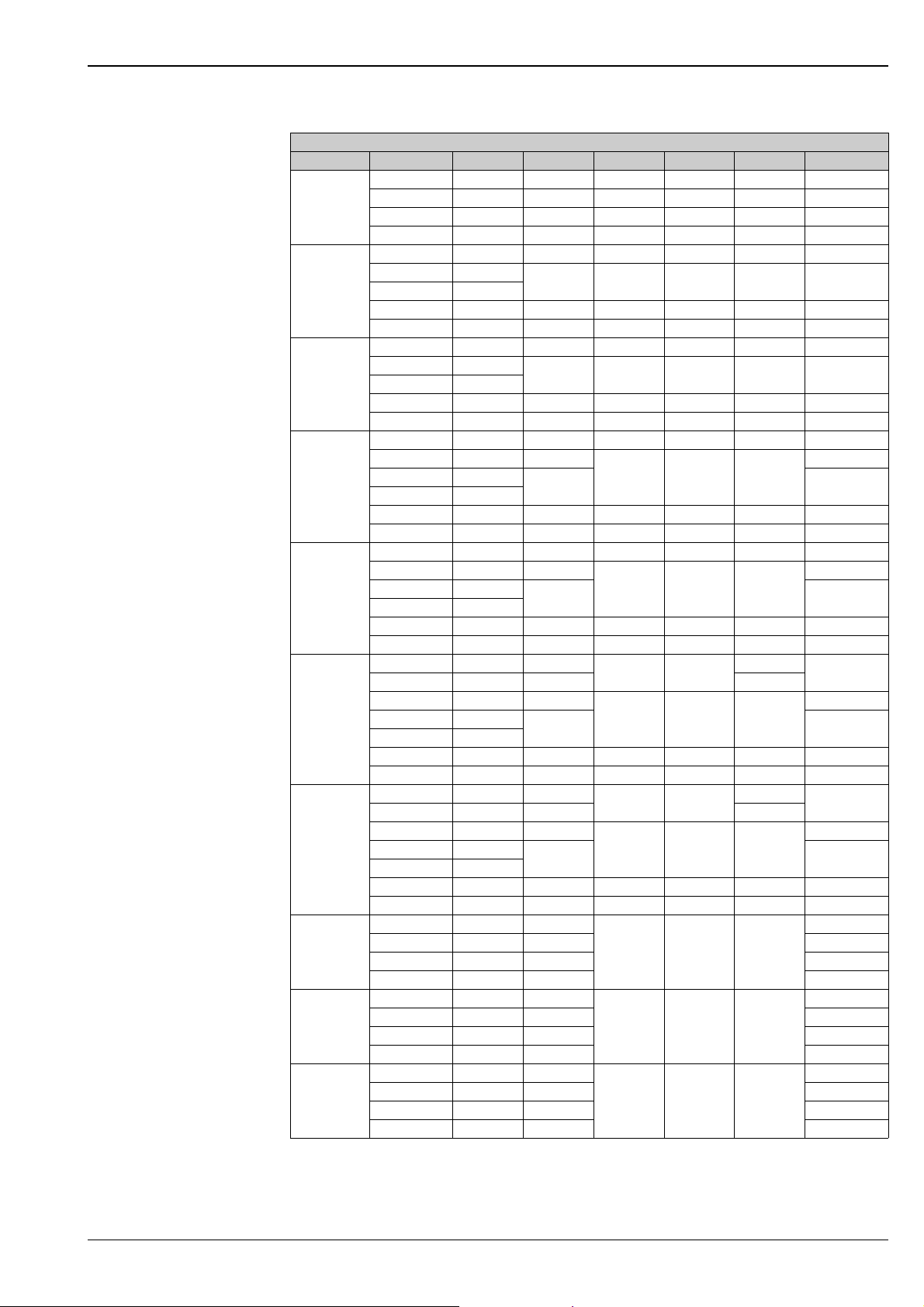
Prowirl 72F, 73F to EN 1092-1 (DIN 2501)
1)
In contrast to the other versions, devices have a sensor in the bluff body.
Only available for 72F.
2)
Pressure ratings are in development for Prowirl 73.
DN Pressure rating d [mm] D [mm] H [mm] L [mm] X [mm] Weight [kg]
PN 40 17.3 95.0 248 200 16 5
15
PN 160
PN 250
Butt-weld
2)
1)
17.3 105.0 288 200 23 7
14.0 130.0 310 248 26 15
1)
14.0 21.3 310 248 - 9
PN 40 28.5 115.0 255 200 18 7
2)
25
PN 100
PN 160
PN 250
Butt-weld
2)
1)
28.5
27.9
140.0 295 200 27 11
24.3 15.0 310 248 28 16
1)
24.3 26.5 310 248 - 9
PN 40 43.1 150.0 263 200 18 10
40
PN 100
PN 160
PN 250
Butt-weld
2)
2)
1)
42.5
41.1
170.0 303 200 31 15
38.1 185.0 315 278 34 21
1)
38.1 48.3 315 278 - 9
PN 40 54.5 165.0 270 200 20 12
2)
50
PN 63
PN 100
PN 160
PN 250
Butt-weld
2)
2)
1)
54.5 180.0
53.9
52.3
195.0 19
310 200 33
47.7 200.0 306 288 38 23
1)
47.7 60.3 306 288 - 9
17
PN 40 82.5 200.0 283 200 24 20
2)
80
100
150
200
PN 63
2)
PN 100
2)
PN 160
1)
PN 250
Butt-weld
PN 16 107.1 220.0
PN 40 107.1 235.0 24
2)
PN 63
2)
PN 100
2)
PN 160
1)
PN 250
Butt-weld
PN 16 159.3 285.0
PN 40 159.3 300.0 28
2)
PN 63
2)
PN 100
2)
PN 160
1)
PN 250
Butt-weld
PN 10 207.3 340.0
PN 16 207.3 340.0 62
PN 25 206.5 360.0 68
81.7 215.0
80.9
76.3
230.0
323 200 39
73.7 255.0 311 325 46 41
1)
73.7 95.7 311 325 - 13
295 250
106.3 250.0
104.3
98.3
265.0 42
335 250 49
97.3 300.0 323 394 54 64
1)
97.3 125.7 323 394 - 21
319 300
157.1 345.0
154.1
146.3
355.0
359 300 64
131.8 390.0 339 566 68 152
1)
131.8 168.3 339 566 - 53
348 300 42
20
22
24
27
27
39
51
86
88
63
PN 40 206.5 375.0 72
250
PN 10 260.4 395.0
PN 16 260.4 405.0 92
PN 25 258.8 425.0 100
375 380 48
88
PN 40 258.8 450.0 111
300
PN 10 309.7 445.0
PN 16 309.7 460.0 129
PN 25 307.9 485.0 140
398 450 51
121
PN 40 307.9 515.0 158
Endress+Hauser 23
Page 24
Proline Prowirl 72F, 72W, 73F, 73W
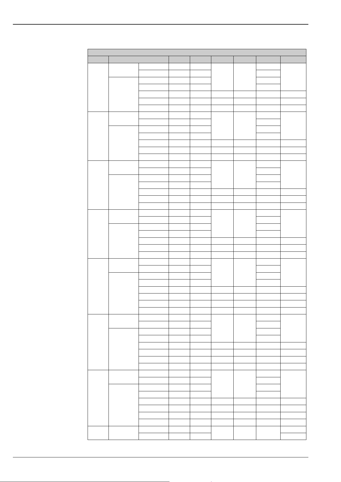
Prowirl 72F, 73F to ANSI B16.5
DN Pressure rating d [mm] D [mm] H [mm] L [mm] X [mm] Weight [kg]
Schedule 40
½"
Schedule 80
Schedule 40
1"
Schedule 80
Schedule 40
1½"
Schedule 80
Schedule 40
2"
Schedule 80
Schedule 40
3"
Schedule 80
Schedule 40
4"
Schedule 80
Schedule 40
6"
Schedule 80
8" Schedule 40
Cl. 150 15.7 88.9
Cl. 300 15.7 95.0 14.2
Cl. 150 13.9 88.9 11.2
248 200
Cl. 300 13.9 95.0 14.2
2)
Cl. 600
Cl. 1500
Butt-weld
13.9 95.3 288 200 23 6
1)
14.0 120.6 310 262 22.3 13
1)
14.0 21.3 310 248 - 9
Cl. 150 26.7 107.9
Cl. 300 26.7 123.8 19.1
Cl. 150 24.3 107.9 15.7
255 200
Cl. 300 24.3 123.8 19.1
2)
Cl. 600
Cl. 1500
Butt-weld
24.3 124.0 295 200 27 9
1)
24.3 149.3 310 287.7 28.4 17
1)
24.3 33.4 310 248 - 9
Cl. 150 40.9 127.0
Cl. 300 40.9 155.6 20.6
Cl. 150 38.1 127.0 17.5
263 200
Cl. 300 38.1 155.6 20.6
2)
Cl. 600
Cl. 1500
Butt-weld
38.1 155.4 303 200 31 13
1)
38.1 177.8 315 305.8 31.7 20
1)
38.1 48.3 315 278 - 9
Cl. 150 52.6 152.4
Cl. 300 52.6 165.0 22.4
Cl. 150 49.2 152.4 19.1
270 200
Cl. 300 49.2 165.0 22.4
2)
Cl. 600
Cl. 1500
Butt-weld
49.2 165.1 310 200 33 14
1)
47.7 215.9 306 344 38.1 30
1)
47.7 60.3 306 288 - 9
Cl. 150 78.0 190.5
Cl. 300 78.0 210.0 28.4
Cl. 150 73.7 190.5 23.9
283 200
Cl. 300 73.7 210.0 28.4
2)
Cl. 600
Cl. 900
Cl. 1500
Butt-weld
73.7 209.6 323 200 39 22
1)
73.7 241.3 311 349 38.1 37
1)
73.7 266.7 311 380.4 47.7 49
1)
73.7 95.7 311 325 - 13
Cl. 150 102.4 228.6
Cl. 300 102.4 254.0 31.8
Cl. 150 97.0 228.6 24.5
295 250
Cl. 300 97.0 254.0 31.8
2)
Cl. 600
Cl. 900
Cl. 1500
Butt-weld
97.0 273.1 335 250 49 43
1)
97.3 292.1 323 408 44.4 57
1)
97.3 311.1 323 427 53.8 71
1)
97.3 125.7 323 394 - 21
Cl. 150 154.2 279.4
Cl. 300 154.2 317.5 36.6
Cl. 150 146.3 279.4 25.4
319 300
Cl. 300 146.3 317.5 36.6
2)
Cl. 600
Cl. 900
Cl. 1500
Butt-weld
Cl. 150 202.7 342.9
Cl. 300 202.7 381.0 76
146.3 355.6 359 300 64 87
1)
131.8 381.0 339 538 55.6 131
1)
131.8 393.7 339 602 82.5 173
1)
131.8 168.3 339 566 - 53
348 300 42
11.2
15.7
17.5
19.1
23.9
24.5
25.4
5
7
10
12
20
27
51
64
24 Endress+Hauser
Page 25
Proline Prowirl 72F, 72W, 73F, 73W
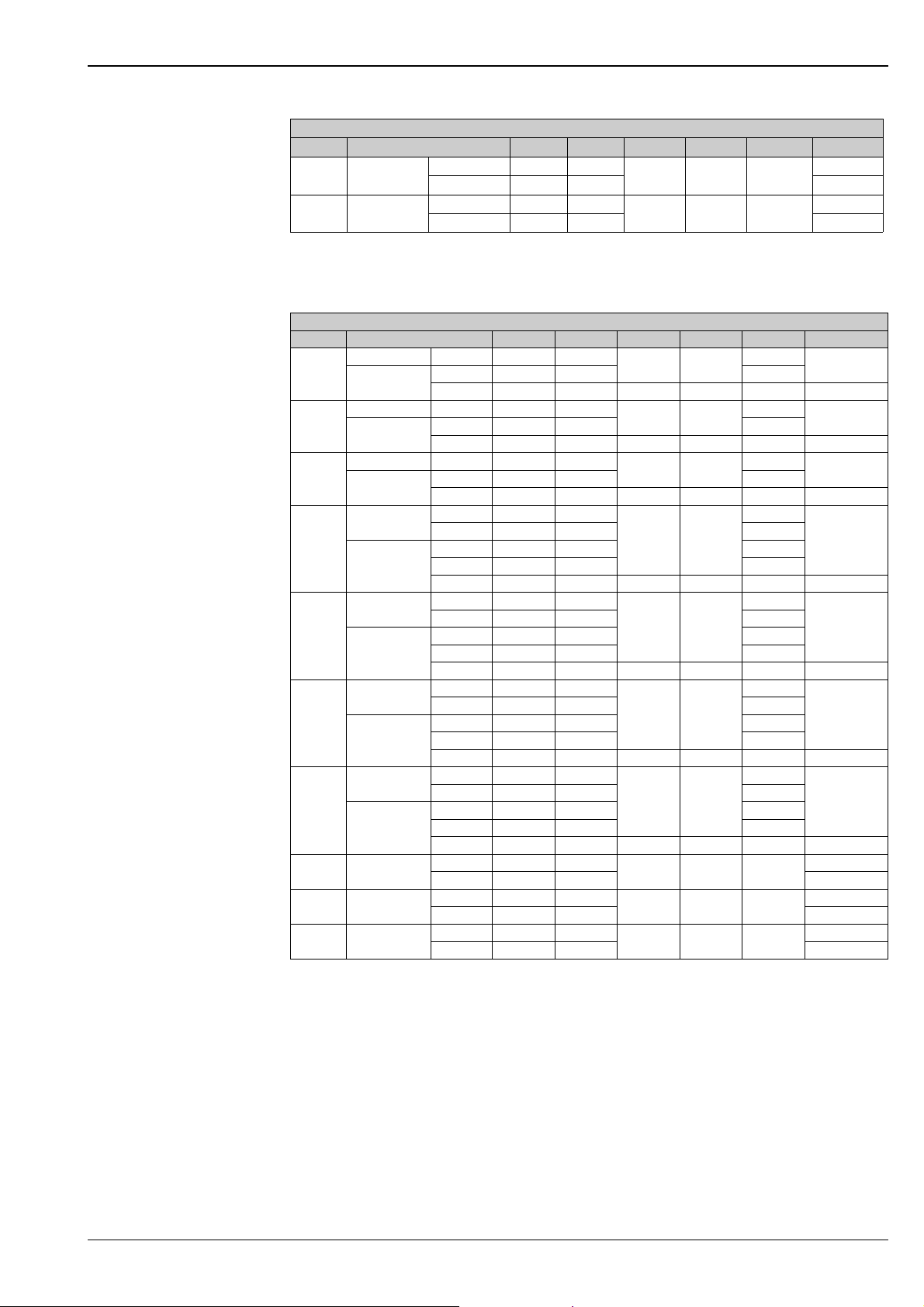
Prowirl 72F, 73F to ANSI B16.5
1)
In contrast to the other versions, devices have a sensor in the bluff body.
Only available for 72F.
2)
Pressure ratings are in development for Prowirl 73.
Prowirl 72F, 73F to JIS B2238
1)
Pressure rating 40 K for Prowirl 73 in development
DN Pressure rating d [mm] D [mm] H [mm] L [mm] X [mm] Weight [kg]
10" Schedule 40
12" Schedule 40
Cl. 150 254.5 406.4
Cl. 300 254.5 444.5 109
Cl. 150 304.8 482.6
Cl. 300 304.8 520.7 162
375 380 48
398 450 60
92
143
DN Pressure rating d [mm] D [mm] H [mm] L [mm] X [mm] Weight [kg]
Schedule 40 20K 16.1 95.0
15
Schedule 80
20K 13.9 95.0 14
1)
40K
Schedule 40 20K 27.2 125.0
25
Schedule 80
20K 24.3 125.0 16
1)
40K
Schedule 40 20K 41.2 140.0
40
Schedule 80
Schedule 40
50
Schedule 80
Schedule 40
80
Schedule 80
Schedule 40
100
Schedule 80
Schedule 40
150
Schedule 80
200 Schedule 40
250 Schedule 40
300 Schedule 40
20K 38.1 140.0 18
1)
40K
10K 52.7 155.0
20K 52.7 155.0 18
10K 49.2 155.0 16
20K 49.2 155.0 18
1)
40K
10K 78.1 185.0
20K 78.1 200.0 22
10K 73.7 185.0 18
20K 73.7 200.0 22
1)
40K
10K 102.3 210.0
20K 102.3 225.0 24
10K 97.0 210.0 18
20K 97.0 225.0 24
1)
40K
10K 151.0 280.0
20K 151.0 305.0 28
10K 146.3 280.0 22
20K 146.3 305.0 28
1)
40K
10K 202.7 330.0
20K 202.7 350.0 64
10K 254.5 400.0
20K 254.5 430.0 104
10K 304.8 445.0
20K 304.8 480.0 134
248 200
13.9 115.0 288 200 23 8
255 200
24.3 130.0 295 200 27 10
263 200
38.1 160.0 303 200 31 14
270 200
49.2 165.0 310 200 33 15
283 200
73.7 210.0 323 200 39 24
295 250
97.0 240.0 335 250 49 36
319 300
146.6 325.0 359 300 64 77
348 300 42
375 380 48
398 450 51
14
16
18
16
18
18
22
5
7
10
12
20
27
51
58
90
119
Endress+Hauser 25
Page 26
Proline Prowirl 72F, 72W, 73F, 73W
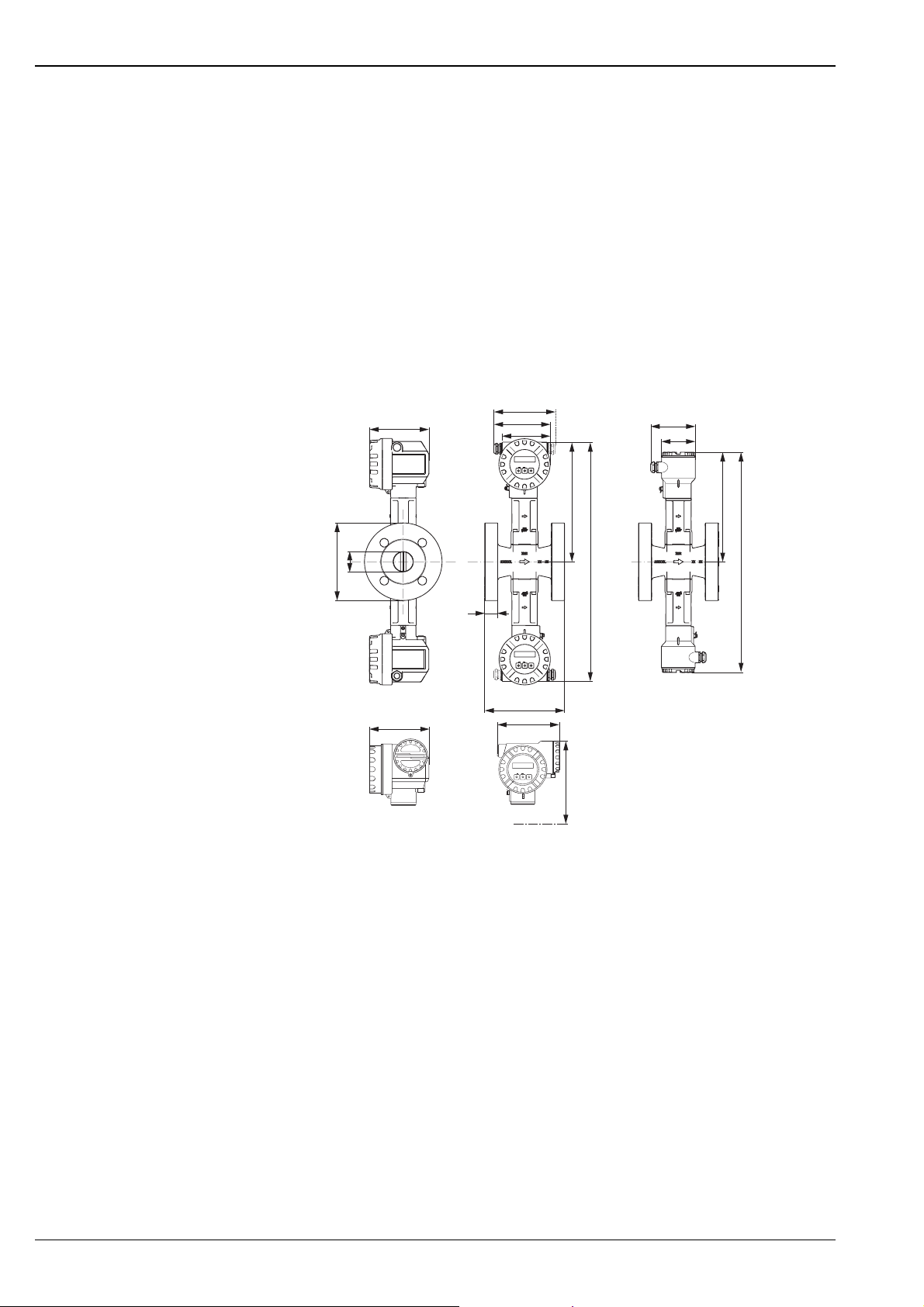
Dimensions of Prowirl 72F, Dualsens version
Flanged version to:
• EN 1092-1 (DIN 2501), Ra = 6.3...12.5 mm
• Raised face to:
– EN 1092-1 Form B1 (DIN 2526 Form C), PN 10...40, Ra = 6.3...12.5 mm,
optional with groove to EN1091-1 Form D (DIN 2512 Form N)
– EN 1092-1 Form B2 (DIN 2526 Form E), PN 63...100, Ra = 1.6...3.2 mm
– DIN 2526 Form E, PN 160...2503), Ra = 1.6...3.2 mm
• ANSI B16.5, Class 150...15001) 2), Ra = 125...250 min2)
• JIS B2238, 10...40K1), Ra = 125...250 min
1)
Prowirl 73F: PN63...160, Cl 600 and 40K in development
2)
Prowirl 73F: only Class 150...600
3) Prowirl 73F: only PN 160
161...181**
149 (142)*
141...151**
121
-
1)
BA
Esc
+
E
1) 2)
105
95
H
d
D
2xH
H–42.5
x
Esc
-
+
E
L
-
161
Esc
+
E
C
151 (144)*
N
A
P
N
S
U
R
N
E
G
T
Ö
N
S
O
R
I
U
F
R
U
S
F
V
T
U
T
N
O
E
H
N
E
S
C
S
N
I
A
I
P
WARNUNG
N
O
N
E
N
AVERTISSEMENT
WARNING
K
T
E
I
E
U
A
I
L
V
E
P
C
IN
T
R
I
E
I
G
C
E
H
R
N
T
W
E
H
X
E
P
H
L
P
O
S
S
O
I
V
M
E
T
A
H+7
A = Standard, Ex i and Ex n version
B = Remote version
C = Ex d version (transmitter)
* The following dimensions change as follows in the blind version (without local operation):
– Standard, Ex i and Ex n version: the dimension 149 mm changes to 142 mm in the blind version.
– Ex d version: the dimension 151 mm changes to 144 mm in the blind version.
** The dimension depends on the cable gland used.
2xH–85
A0003600
Note!
The weight data refer to the compact version.
26 Endress+Hauser
Page 27
Proline Prowirl 72F, 72W, 73F, 73W
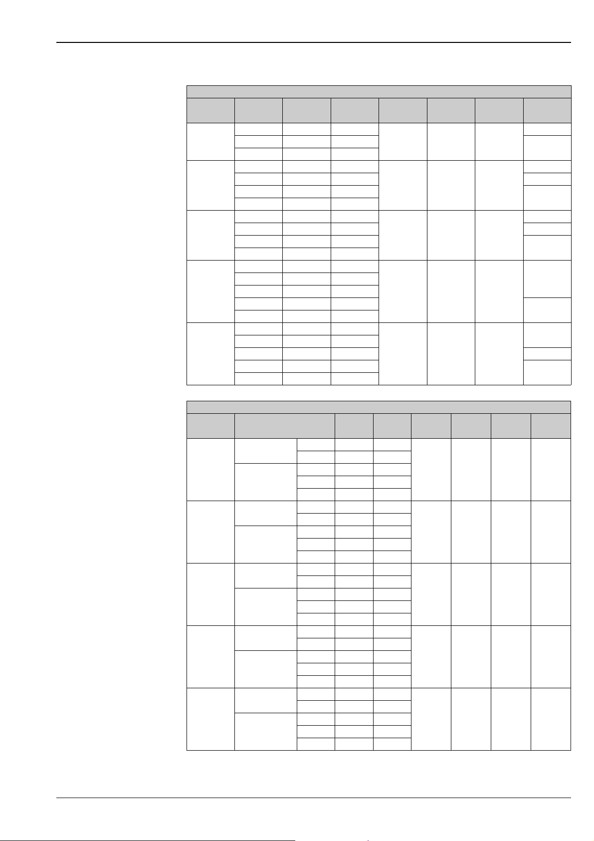
Prowirl 72F Dualsens version to EN 1092-1 (DIN 2501)
DN Pressure
DIN/JIS [mm] [mm] [mm] [mm] [mm] [kg]
40
50
80
100
150
rating
PN 40 43.1 150.0
PN 100 42.5 170.0
PN 160 41.1 170.0
PN 40 54.5 165.0
PN 63 54.5 180.0 20
PN 100 53.9 195.0
PN 160 52.3 195.0
PN 40 82.5 200.0
PN 63 81.7 215.0 27
PN 100 80.9 230.0
PN 160 76.3 230.0
PN 16 107.1 220.0
PN 63 106.3 250.0
PN 100 104.3 265.0
PN 160 98.3 265.0
PN 16 159.3 285.0
PN 40 159.3 300.0
PN 63 157.1 345.0 89
PN 100 154.1 355.0
PN 160 146.3 355.0
d D H L X Weight
16
303 200 31
310 200 33
323 200 39
335 250 49
359 300 64
18
18
22
25
30
42PN 40 107.1 235.0
45
80
91
Prowirl 72F Dualsens version to ANSI B16.5
DN Pressure rating d D H L X Weight
ANSI [mm] [mm] [mm] [mm] [mm] [kg]
Schedule 40 Cl. 150 40.9 127.0
Cl. 300 40.9 155.6
1½"
2"
3"
4"
6"
Schedule 80 Cl. 150 38.1 127.0
Cl. 300 38.1 155.6
Cl. 600 38.1 155.4
Schedule 40 Cl. 150 52.6 152.4
Cl. 300 52.6 165.0
Schedule 80 Cl. 150 49.2 152.4
Cl. 300 49.2 165.0
Cl. 600 49.2 165.1
Schedule 40 Cl. 150 78.0 190.5
Cl. 300 78.0 210.0
Schedule 80 Cl. 150 73.7 190.5
Cl. 300 73.7 210.0
Cl. 600 73.7 209.6
Schedule 40 Cl. 150 102.4 228.6
Cl. 300 102.4 254.0
Schedule 80 Cl. 150 97.0 228.6
Cl. 300 97.0 254.0
Cl. 600 97.0 273.1
Schedule 40 Cl. 150 154.2 279.4
Cl. 300 154.2 317.5
Schedule 80 Cl. 150 146.3 279.4
Cl. 300 146.3 317.5
Cl. 600 146.3 355.6
303 200 31 16
310 200 33 18
323 200 39 25
335 250 49 42
359 300 64 80
Endress+Hauser 27
Page 28
Proline Prowirl 72F, 72W, 73F, 73W
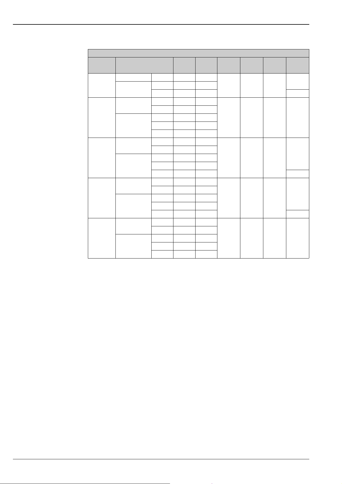
Prowirl 72F Dualsens version to JIS B2238
DN Pressure rating d D H L X Weight
DIN/JIS [mm] [mm] [mm] [mm] [mm] [kg]
40 Schedule 40 20K 41.2 140.0
Schedule 80 20K 38.1 140.0
40K 38.1 160.0 17
Schedule 40 10K 52.7 155.0
20K 52.7 155.0
50
80
100
150 Schedule 40 10K 151.0 280.0
Schedule 80 10K 49.2 155.0
20K 49.2 155.0
40K 49.2 165.0
Schedule 40 10K 78.1 185.0
20K 78.1 200.0
Schedule 80 10K 73.7 185.0
20K 73.7 200.0
40K 73.7 210.0 27
Schedule 40 10K 102.3 210.0
20K 102.3 225.0
Schedule 80 10K 97.0 210.0
20K 97.0 225.0
40K 97.0 240.0 49
20K 151.0 305.0
Schedule 80 10K 146.3 280.0
20K 146.3 305.0
40K 146.6 325.0
303 200 31
310 200 33 18
323 200 39
335 250 49
359 300 64 80
16
25
42
28 Endress+Hauser
Page 29
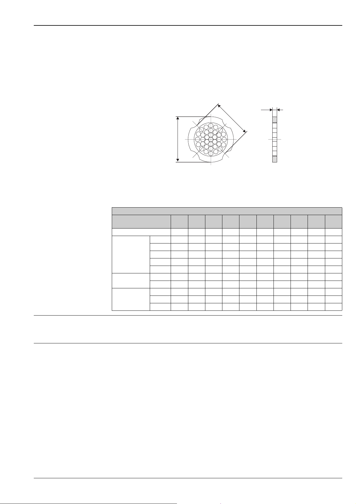
Proline Prowirl 72F, 72W, 73F, 73W
Dimensions of flow conditioner (accessory)
Dimensions to:
• EN 1092-1 (DIN 2501)
• ANSI B16.5
• JIS B2238
Material 1.4435 (316L), in conformity with NACE MR 0175 and MR 0103
D2
s
D1
D1: The flow conditioner is fitted at the external diameter between the bolts.
D2: The flow conditioner is fitted at the indentations between the bolts.
Flow conditioner to EN (DIN) / ANSI / JIS
DN 15 /½"25 /1"40 /
s [mm] 2.0 3.5 5.3 6.8 10.1 13.3 20.0 26.3 33.0 39.6
EN (DIN)
Weight in [kg]
ANSI
Weight in [kg]
JIS
Weight in [kg]
PN 10 0.04 0.12 0.30 0.50 1.40 2.40 6.30 11.5 25.7 36.4
PN 16 0.04 0.12 0.30 0.50 1.40 2.40 6.30 12.3 25.7 36.4
PN 25 0.04 0.12 0.30 0.50 1.40 2.40 7.80 12.3 25.7 36.4
PN 40 0.04 0.12 0.30 0.50 1.40 2.40 7.80 15.9 27.5 44.7
PN 63 0.05 0.15 0.40 0.60 1.40 2.40 7.80 15.9 27.5 44.7
Cl. 150 0.030.120.300.501.202.706.3012.325.736.4
Cl. 300 0.040.120.300.501.402.707.8015.827.544.6
10K 0.06 0.14 0.31 0.47 1.1 1.8 4.5 9.2 15.8 26.5
20K 0.06 0.14 0.31 0.47 1.1 1.8 5.5 9.2 19.1 26.5
40K 0.06 0.14 0.31 0.5 1.3 2.1 6.2 - - -
50 /2"80 /3"100 /4"150 /6"200 /8"250 /
1½"
300 /
10"
A0001941
12"
Weight • Weight of Prowirl 72W, 73W → see dimension table on Page 21.
• Weight of Prowirl 72 F, 73 F → see dimension tables on Page 22 ff.
• Weight of flow conditioner to EN (DIN) /ANSI / JIS → see dimension table on Page 29.
Material Transmitter housing
• Powder-coated die-cast aluminum AlSi10Mg
– in accordance with EN 1706/EN AC-43400 (EEx-d/XP version: cast aluminum EN 1706/EN AC-
43000)
Sensor
• Flanged version
– Stainless steel, A351-CF3M (1.4404), in conformity with NACE MR 0175 and MR0103
– Pressure ratings PN 250, Cl 900…1500 and butt-weld version (only for Prowirl 72) 1.4571 (316Ti;
UNS S31635); in conformity with NACE MR0175 and MR0103
• Alloy C-22 version (only for Prowirl 72)
– Alloy C-22 2.4602 (A 494-CX2MW/N 26022); in conformity with NACE MR0175 and MR0103
• Wafer version
– Stainless steel, A351-CF3M (1.4404), in conformity with NACE MR 0175 and MR0103
Endress+Hauser 29
Page 30

Proline Prowirl 72F, 72W, 73F, 73W
Flanges
• EN (DIN)
– Stainless steel, 316/316L/1.4404, in conformity with NACE MR 0175 and MR 0103
– DN 15...150 with pressure ratings PN 63-160 (in development for Prowirl 73) and nominal diameters DN
200-300: fully cast construction A351-CF3M (1.4404); in conformity with NACE MR 0175 and MR0103
– Pressure rating PN 250 (only for Prowirl 72) 1.4571 (316Ti, UNS S31635);
in conformity with NACE MR 0175 and MR 0103
• ANSI and JIS
– Stainless steel, 316/316L, in conformity with NACE MR 0175 and MR0103
– ½"...6" with pressure ratings Cl 600 (in development for Prowirl 73), DN 15...150 with pressure rating
40 K, (in development for Prowirl 73), nominal diameters 8"-12" and DN 200-300:
fully cast construction A351-CF3M; in conformity with NACE MR 0175 and MR0103
• Pressure ratings Cl 900…1500: 316/316L; in conformity with NACE MR0175 and MR0103
(only Prowirl 72)
• Alloy C-22 version (EN/DIN/ANSI/JIS, only Prowirl 72)
– Alloy C-22 2.4602 (A 494-CX2MW/N 26022); in conformity with NACE MR 0175 and MR 0103
DSC sensor (Differential Switched Capacitor; capacitive sensor)
• Wetted parts (marked as "wet" on the DSC sensor flange):
– Standard for pressure ratings up to PN 40, Cl 300, JIS 40 K (apart from Dualsens version):
Stainless steel 1.4435 (316L), in conformity with NACE MR 0175 and MR 0103
– Pressure ratings PN 63…160, Cl 600, 40 K and Dualsens version (in development for Prowirl 73):
Inconel 2.4668/N 07718 (B637) (Inconel 718); in conformity with NACE MR 0175 and MR 0103
– Pressure ratings PN 250, Cl 900…1500 and butt-weld version (only for Prowirl 72): titanium Gr. 5
(B-348; UNS R50250; 3.7165)
– Alloy C-22 sensor (only for Prowirl 72):
Alloy C-22, 2.4602/N 06022; in conformity with NACE MR 0175 and MR 0103
Non- wetted parts
• Non-wetted parts:
– Stainless steel 1.4301 (304)
Support
• Support:
– Stainless steel, 1.4308 (CF8)
Pressure ratings PN 250, Cl 900…1500 and butt-weld version (only for Prowirl 72): 1.4305 (303)
Seals
• Graphite (Grafoil)
•Viton
• Kalrez 6375
• Gylon (PTFE) 3504
Human interface
Display elements Liquid crystal display, double-spaced, plain text display, 16 characters per line
Display can be configured individually, e.g. for measured variables and status values, totalizers
Operating elements (HART) Local operation with three keys (O, S, F)
Quick Setup for quick commissioning
Operating elements accessible also in Ex-zones
Remote operation Remote operation possible via:
•HART
•PROFIBUS PA
• FOUNDATION Fieldbus
• Endress+Hauser Service Protocol
30 Endress+Hauser
Page 31

Proline Prowirl 72F, 72W, 73F, 73W
Certificates and approvals
CE mark The device is in conformity with the statutory requirements of the EC Directives. Endress+Hauser confirms
successful testing of the device by affixing the CE mark.
C-tick The measuring system is in conformity with the EMC requirements of the Australian Communications
Authority (ACA).
Ex-approval • Ex i and Ex n:
–ATEX/CENELEC
II1/2G, EEx ia IIC T1...T6 (T1...T4 for PROFIBUS PA and FOUNDATION Fieldbus)
II1/2GD, EEx ia IIC T1...T6 (T1...T4 for PROFIBUS PA and FOUNDATION Fieldbus)
II1G, EEx ia IIC T1...T6 (T1...T4 for PROFIBUS PA and FOUNDATION Fieldbus)
II2G, EEx ia IIC T1...T6 (T1...T4 for PROFIBUS PA and FOUNDATION Fieldbus)
II3G, EEx nA IIC T1...T6 X (T1...T4 X for PROFIBUS PA and FOUNDATION Fieldbus)
–FM
Class I/II/III Div. 1/2, Group A...G; Class I Zone 0, Group IIC
–CSA
Class I/II/III Div. 1/2, Group A...G; Class I Zone 0, Group IIC
Class II Div. 1, Group E...G
Class III
• Ex d:
–ATEX/CENELEC
II1/2G, EEx d [ia] IIC T1...T6 (T1...T4 for PROFIBUS PA and FOUNDATION Fieldbus)
II1/2GD, EEx ia IIC T1...T6 (T1...T4 for PROFIBUS PA and FOUNDATION Fieldbus)
II2G, EEx d [ia] IIC T1...T6 (T1...T4 for PROFIBUS PA and FOUNDATION Fieldbus)
–FM
Class I/II/III Div. 1, Groups A...G
–CSA
Class I/II/III Div. 1/2 Groups A...G
Class II Div. 1, Groups E...G
Class III
More information on the Ex-approvals can be found in the separate Ex-documentation.
Pressure measuring device approval
Certification FOUNDATION Fieldbus
Certification PROFIBUS PA The flowmeter has successfully passed all test procedures and is certified and registered by the PNO (PROFIBUS
Devices with a nominal diameter smaller than or equal to DN 25 correspond to Article 3 (3) of the EC Directive
97/23/EC (Pressure Equipment Directive). Optional approvals to Category III are also available for larger
nominal diameters, where necessary (depending on fluid and process pressure). The devices are suitable for all
media as well as unstable gases and have been designed and manufactured according to good engineering
practice.
The flowmeter has successfully passed all test procedures and is certified and registered by the Fieldbus
FOUNDATION. The device thus meets all the requirements
of the specifications following:
• Certified to FOUNDATION Fieldbus Specification
• The device meets all the specifications of the FOUNDATION Fieldbus-H1.
• Interoperability Test Kit (ITK), revision status 4.5 (device certification number available on request):
The device can also be operated with certified devices of other manufacturers.
• Physical Layer Conformance Test of the Fieldbus FOUNDATION
User Organization). The device thus meets all the requirements of the specifications following:
• Certified to PROFIBUS PA Profile Version 3.0 (device certification number: on request)
• The device can also be operated with certified devices of other manufacturers (interoperability)
Endress+Hauser 31
Page 32

Proline Prowirl 72F, 72W, 73F, 73W
Other standards and guidelines
Functional safety Prowirl 72: SIL 2 in accordance with IEC 61508 / IEC 61511-1
• EN 60529: Degrees of protection by housing (IP code).
• EN 61010: Protection measures for electrical equipment for measurement, control, regulation and
laboratory procedures.
• EN 61326/A1: Electromagnetic compatibility (EMC requirements).
• NAMUR NE 21: Electromagnetic compatibility (EMC) of industrial process and laboratory control
equipment.
• NAMUR NE 43: Standardization of the signal level for the breakdown information of digital transmitters with
analog output signal.
• NACE Standard MR 0103: Standard Material Requirements - Materials Resistant to Sulfide Stress Cracking
in Corrosive Petroleum Refining Environments
• NACE Standard MR 0175: Standard Material Requirements - Sulfide Stress Cracking Resistant Metallic
Materials for Oilfield Equipment
• VDI 2643: Measurement of fluid flow by means of vortex flowmeters.
• ANSI/ISA-S82.01: Safety Standard for Electrical and Electronic Test, Measuring, Controlling and
related Equipment - General Requirements. Pollution degree 2, Installation Category II
• CAN/CSA-C22.2 No. 1010.1-92: Safety Standard for Electrical Equipment for Measurement and Control
and Laboratory Use. Pollution degree 2, Installation Category II
• The International Association for the Properties of Water and Steam - Release on the IAPWS Industrial
Formulation 1997 for the Thermodynamic Properties of Water and Steam
• ASME International Steam Tables for Industrial Use (2000)
• American Gas Association (1962): A.G.A. Manual for the Determination of Supercompressibility
Factors for Natural Gas - PAR Research Project NX-19.
Prowirl 73: SIL 1
Ordering information
Ordering information and detailed information on the order code can be obtained from your Endress+Hauser
Service Organization.
Additional ordering information for Prowirl 72:
You can order your Prowirl 72 preconfigured.
For this purpose, the following information is needed when ordering:
• 20 mA value = at which measured value a current of 20 mA should be set
• Pulse value (if the device has a pulse output)
If you require the flow output in units of mass, we need:
• The average operating density of the fluid including the enginering unit to be used
If you require the flow output in units of corrected volume, we need:
• The operating and reference density of the fluid including the enginering unit to be used
The measuring device can be reset to the delivery state indicated in the order at any time.
Additional ordering information for Prowirl 73:
You can order your Prowirl 73 as preconfigured.
For this purpose, the following information is needed when ordering:
• Fluid (saturated steam, superheated steam, water or compressed air)
• Average operating pressure in bar absolute (not needed for saturated steam)
• 4 mA value = at which measured value (e.g. 50 kg/h) a current of 4
mA should be output, incl. enginering unit to be used
• 20 mA value = at which measured value (e.g. 1,000 kg/h) a current of 20
mA should be output, incl. enginering unit to be used
• Pulse value (if the device has a pulse output), incl. enginering unit to be used
The measuring device can be reset to the delivery state indicated in the order at any time.
32 Endress+Hauser
Page 33

Proline Prowirl 72F, 72W, 73F, 73W
Accessories
• Spare parts as per separate price list
• Wafer version mounting set
• Pipe and wall mounting kit for transmitter remote version DK5WM-B
• Replacement transmitter
• Universal flow and energy computer RMC 621
• Steam computer RMS 621
• Flow conditioner
• HART Communicator DXR 375 handheld terminal
• Active barrier preline RN 221 N
• Resistance thermometer Omnigrad TR10 (HART-enabled and burst-enabled, for delta heat applications with
• Pressure transmitter Cerabar M (HART-enabled and burst-enabled for superheated steam and gas
• Pressure transmitter Cerabar T or Cerabar S (PROFIBUS PA, FOUNDATION Fieldbus)
• Process display RIA 250, RIA 251
• Field display unit RIA 261 or RID 261 (PROFIBUS PA)
• Applicator
• ToF Tool - Fieldtool Package
• Fieldgate FXA 520 (HART), FXA 720 (PROFIBUS PA) for data transmission
• Paperless Recorder Ecograph T for displaying, recording and communication of data
Prowirl 73)
applications with Prowirl 73)
Documentation
• Operating Instructions Proline Prowirl 72
• Operating Instructions Proline Prowirl 72 PROFIBUS PA
• Operating Instructions Proline Prowirl 72 FOUNDATION Fieldbus
• Operating Instructions Proline Prowirl 73
• Operating Instructions Proline Prowirl 73 PROFIBUS PA
• Operating Instructions Proline Prowirl 73 FOUNDATION Fieldbus
• Related Ex-documentation
• Supplementary documentation on Pressure Equipment Directive
Registered trademarks
•GYLON
•HART
• INCONEL®
•KALREZ
• ToF Tool - Fieldtool® Package, Fieldcheck®, Applicator®
®
Registered trademark of Garlock Sealing Technologies, Palmyar, NY, USA
®
Registered trademark of the HART Communication Foundation, Austin, USA
Registered trademark of Inco Alloys International Inc., Huntington, USA
®
, VITON®
Registered trademarks of E.I. Du Pont de Nemours & Co., Wilmington, USA
Registered or registration-pending trademarks of Endress+Hauser Flowtec AG, Reinach, CH
Subject to modifications and amendments!
Endress+Hauser 33
Page 34

Proline Prowirl 72F, 72W, 73F, 73W
34 Endress+Hauser
Page 35

Proline Prowirl 72F, 72W, 73F, 73W
Endress+Hauser 35
Page 36

Proline Prowirl 72F, 72W, 73F, 73W
International Head Quarter
Endress+Hauser
GmbH+Co. KG
Instruments International
Colmarer Str. 6
79576 Weil am Rhein
Deutschland
Tel. +49 76 21 9 75 02
Fax +49 76 21 9 75 34 5
www.endress.com
[email protected]
TI070D/06/en/12.05
71005481
FM+SGML 6.0 ProMoDo
 Loading...