

Page 1
BA01769D/06/EN/01.17
71382746
Valid as of version
01.00.zz (Device firmware)
Products Solutions Services
Operating Instructions
Proline Prosonic Flow E 100
HART
Ultrasonic time-of-flight flowmeter
Page 2

Proline Prosonic Flow E 100 HART
• Make sure the document is stored in a safe place such that it is always available when
working on or with the device.
• To avoid danger to individuals or the facility, read the "Basic safety instructions" section
carefully, as well as all other safety instructions in the document that are specific to
working procedures.
• The manufacturer reserves the right to modify technical data without prior notice. Your
Endress+Hauser Sales Center will supply you with current information and updates to
these instructions.
2 Endress+Hauser
Page 3

Proline Prosonic Flow E 100 HART Table of contents
Table of contents
1 About this document ................ 5
1.1 Document function ..................... 5
1.2 Symbols used .......................... 5
1.2.1 Safety symbols .................. 5
1.2.2 Electrical symbols ................ 5
1.2.3 Tool symbols .................... 5
1.2.4 Symbols for
certain types of information ......... 6
1.2.5 Symbols in graphics ............... 6
1.3 Documentation ........................ 6
1.3.1 Standard documentation ........... 7
1.3.2 Supplementary device-dependent
documentation .................. 7
1.4 Registered trademarks ................... 7
2 Basic safety instructions ............ 8
2.1 Requirements for the personnel ............ 8
2.2 Designated use ........................ 8
2.3 Workplace safety ....................... 9
2.4 Operational safety ...................... 9
2.5 Product safety ......................... 9
2.6 IT security ........................... 10
3 Product description ................ 11
3.1 Product design ........................ 11
3.1.1 Device version with HART
communication type ............. 11
4 Incoming acceptance and product
identification ..................... 12
4.1 Incoming acceptance ................... 12
4.2 Product identification ................... 12
4.2.1 Transmitter nameplate ........... 13
4.2.2 Sensor nameplate ............... 14
5 Storage and transport ............. 15
5.1 Storage conditions ..................... 15
5.2 Transporting the product ................ 15
5.2.1 Measuring devices without lifting
lugs ......................... 15
5.2.2 Measuring devices with lifting lugs .. 16
5.2.3 Transporting with a fork lift ........ 16
5.3 Packaging disposal ..................... 16
6 Installation ....................... 16
6.1 Installation conditions .................. 16
6.1.1 Mounting position ............... 16
6.1.2 Requirements from environment and
process ....................... 18
6.2 Mounting the measuring device ........... 19
6.2.1 Required tools .................. 19
6.2.2 Preparing the measuring device ..... 19
6.2.3 Mounting the measuring device ..... 19
6.2.4 Turning the display module ........ 20
6.3 Post-mounting check ................... 20
7 Electrical connection .............. 21
7.1 Connection conditions .................. 21
7.1.1 Required tools .................. 21
7.1.2 Requirements for connecting cable ... 21
7.1.3 Terminal assignment ............. 22
7.1.4 Preparing the measuring device ..... 22
7.2 Connecting the measuring device .......... 23
7.2.1 Connecting the transmitter ........ 23
7.2.2 Ensuring potential equalization ..... 24
7.3 Special connection instructions ............ 25
7.3.1 Connection examples ............. 25
7.4 Ensuring the degree of protection .......... 26
7.5 Post-connection check .................. 26
8 Operation options ................. 27
8.1 Overview of operating options ............ 27
8.2 Structure and function of the operating
menu .............................. 28
8.2.1 Structure of the operating menu .... 28
8.2.2 Operating philosophy ............ 29
8.3 Access to the operating menu via the web
browser ............................. 30
8.3.1 Function range ................. 30
8.3.2 Prerequisites ................... 30
8.3.3 Establishing a connection ......... 31
8.3.4 Logging on .................... 32
8.3.5 User interface .................. 33
8.3.6 Disabling the Web server .......... 34
8.3.7 Logging out .................... 34
8.4 Access to the operating menu via the
operating tool ........................ 35
8.4.1 Connecting the operating tool ...... 35
8.4.2 Field Xpert SFX350, SFX370 ....... 36
8.4.3 FieldCare ..................... 36
8.4.4 DeviceCare .................... 38
8.4.5 AMS Device Manager ............ 38
8.4.6 SIMATIC PDM .................. 38
8.4.7 Field Communicator 475 .......... 38
9 System integration ................ 39
9.1 Overview of device description files ......... 39
9.1.1 Current version data for the device ... 39
9.1.2 Operating tools ................. 39
9.2 Measured variables via HART protocol ...... 39
9.3 Other settings ........................ 40
10 Commissioning .................... 43
10.1 Function check ....................... 43
Endress+Hauser 3
Page 4

Table of contents Proline Prosonic Flow E 100 HART
10.2 Switching on the measuring device ......... 43
10.3 Setting the operating language ............ 43
10.4 Configuring the measuring device .......... 43
10.4.1 Defining the tag name ............ 43
10.4.2 Setting the system units .......... 44
10.4.3 Configuring the current output ..... 46
10.4.4 Configuring the pulse/frequency/
switch output .................. 47
10.4.5 Configuring the output
conditioning ................... 54
10.4.6 Configuring the low flow cut off ..... 56
10.5 Advanced settings ..................... 57
10.5.1 Using the parameter to enter the
access code .................... 57
10.5.2 Carrying out a sensor adjustment .... 57
10.5.3 Configuring the totalizer .......... 58
10.5.4 Configuration management ........ 58
10.5.5 Carrying out additional display
configurations .................. 60
10.5.6 Using parameters for device
administration ................. 62
10.6 Simulation ........................... 63
10.7 Protecting settings from unauthorized
access .............................. 65
10.7.1 Write protection via write protection
switch ........................ 66
11 Operation ......................... 67
11.1 Reading the device locking status .......... 67
11.2 Adjusting the operating language .......... 67
11.3 Configuring the display ................. 67
11.4 Reading measured values ................ 67
11.4.1 Process variables ................ 67
11.4.2 System values .................. 68
11.4.3 Output values .................. 69
11.4.4 "Totalizer" submenu .............. 69
11.5 Adapting the measuring device to the process
conditions ........................... 70
11.6 Performing a totalizer reset .............. 70
11.6.1 Function scope of the "Control
Totalizer" parameter ............. 71
11.6.2 Function scope of the "Reset all
totalizers" parameter ............. 71
12 Diagnostics and troubleshooting ... 72
12.1 General troubleshooting ................. 72
12.2 Diagnostic information via light emitting
diodes .............................. 73
12.2.1 Transmitter .................... 73
12.3 Diagnostic information in the Web browser .. 74
12.3.1 Diagnostic options ............... 74
12.3.2 Calling up remedy information ...... 75
12.4 Diagnostic information in FieldCare or
DeviceCare .......................... 75
12.4.1 Diagnostic options ............... 75
12.4.2 Calling up remedy information ...... 76
12.5 Adapting the diagnostic information ....... 76
12.5.1 Adapting the diagnostic behavior .... 76
12.5.2 Adapting the status signal ......... 77
12.6 Overview of diagnostic information ........ 77
12.7 Pending diagnostic events ............... 80
12.8 Diagnostic list ........................ 81
12.9 Event logbook ........................ 81
12.9.1 Reading out the event logbook ...... 81
12.9.2 Filtering the event logbook ........ 82
12.9.3 Overview of information events ..... 82
12.10 Resetting the measuring device ........... 83
12.10.1 Function scope of the "Device reset"
parameter ..................... 83
12.11 Device information .................... 83
12.12 Firmware history ...................... 85
13 Maintenance ...................... 86
13.1 Maintenance tasks ..................... 86
13.1.1 Exterior cleaning ................ 86
13.2 Measuring and test equipment ............ 86
13.3 Endress+Hauser services ................ 86
14 Repairs ........................... 87
14.1 General notes ........................ 87
14.1.1 Repair and conversion concept ...... 87
14.1.2 Notes for repair and conversion ..... 87
14.2 Spare parts .......................... 87
14.3 Endress+Hauser services ................ 87
14.4 Return .............................. 87
14.5 Disposal ............................ 88
14.5.1 Removing the measuring device ..... 88
14.5.2 Disposing of the measuring device ... 88
15 Accessories ....................... 89
15.1 Communication-specific accessories ........ 89
15.2 Service-specific accessories ............... 90
15.3 System components .................... 90
16 Technical data .................... 91
16.1 Application .......................... 91
16.2 Function and system design .............. 91
16.3 Input ............................... 91
16.4 Output ............................. 92
16.5 Power supply ......................... 94
16.6 Performance characteristics .............. 95
16.7 Installation .......................... 96
16.8 Environment ......................... 96
16.9 Process ............................. 97
16.10 Mechanical construction ................ 99
16.11 Operability ......................... 101
16.12 Certificates and approvals .............. 103
16.13 Application packages .................. 104
16.14 Accessories ......................... 104
16.15 Supplementary documentation ........... 104
Index ................................. 106
4 Endress+Hauser
Page 5
Proline Prosonic Flow E 100 HART About this document
DANGER
WARNING
CAUTION
NOTICE
1 About this document
1.1 Document function
These Operating Instructions contain all the information that is required in various phases
of the life cycle of the device: from product identification, incoming acceptance and
storage, to mounting, connection, operation and commissioning through to
troubleshooting, maintenance and disposal.
1.2 Symbols used
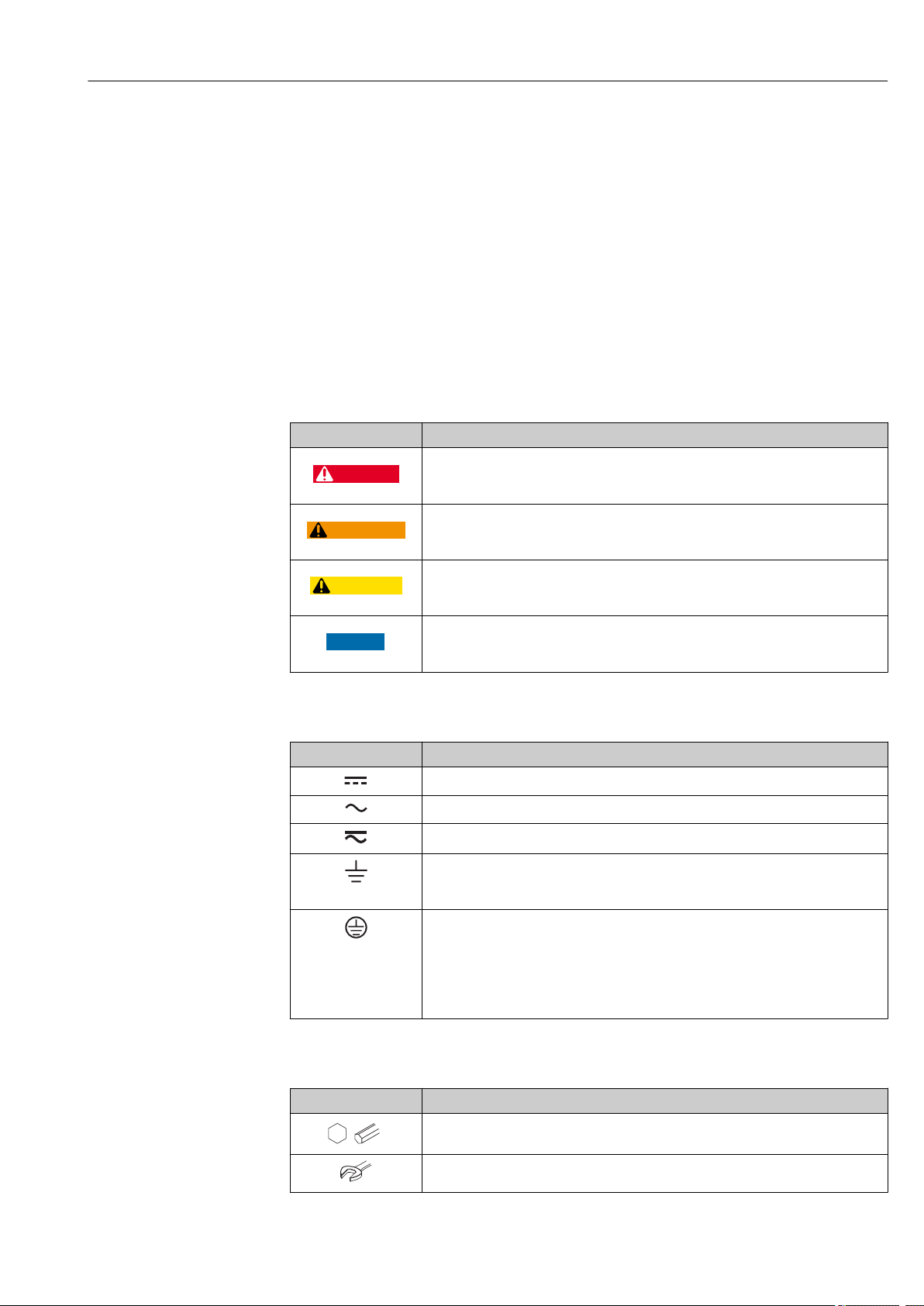
1.2.1 Safety symbols
Symbol Meaning
DANGER!
This symbol alerts you to a dangerous situation. Failure to avoid this situation will
result in serious or fatal injury.
WARNING!
This symbol alerts you to a dangerous situation. Failure to avoid this situation can
result in serious or fatal injury.
CAUTION!
This symbol alerts you to a dangerous situation. Failure to avoid this situation can
result in minor or medium injury.
NOTE!
This symbol contains information on procedures and other facts which do not result in
personal injury.
1.2.2 Electrical symbols
Symbol Meaning
Direct current
Alternating current
Direct current and alternating current
Ground connection
A grounded terminal which, as far as the operator is concerned, is grounded via a
grounding system.
Protective Earth (PE)
A terminal which must be connected to ground prior to establishing any other
connections.
The ground terminals are situated inside and outside the device:
• Inner ground terminal: Connects the protectiv earth to the mains supply.
• Outer ground terminal: Connects the device to the plant grounding system.
1.2.3 Tool symbols
Symbol Meaning
Allen key
Open-ended wrench
Endress+Hauser 5
Page 6
About this document Proline Prosonic Flow E 100 HART
A
1.
1.
-
.
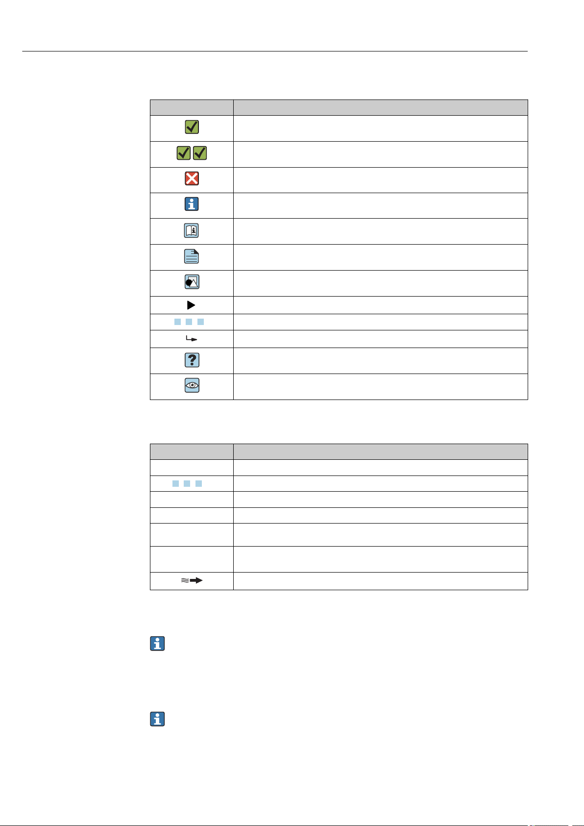
1.2.4 Symbols for certain types of information
Symbol Meaning
Permitted
Procedures, processes or actions that are permitted.
Preferred
Procedures, processes or actions that are preferred.
Forbidden
Procedures, processes or actions that are forbidden.
Tip
Indicates additional information.
Reference to documentation.
Reference to page.
Reference to graphic.
Notice or individual step to be observed.
, 2., 3.… Series of steps.
Result of a step.
Help in the event of a problem.
Visual inspection.
1.2.5 Symbols in graphics
Symbol Meaning
1, 2, 3, ... Item numbers
, 2., 3., … Series of steps
A, B, C, ... Views
A-A, B-B, C-C, ... Sections
Hazardous area
Safe area (non-hazardous area)
Flow direction
1.3 Documentation
For an overview of the scope of the associated Technical Documentation, refer to the
following:
• The W@M Device Viewer : Enter the serial number from the nameplate
(www.endress.com/deviceviewer)
• The Endress+Hauser Operations App: Enter the serial number from the nameplate
or scan the 2-D matrix code (QR code) on the nameplate.
For a detailed list of the individual documents along with the documentation code
→ 104
6 Endress+Hauser
Page 7

Proline Prosonic Flow E 100 HART About this document
1.3.1 Standard documentation
Document type Purpose and content of the document
Technical Information Planning aid for your device
The document contains all the technical data on the device and provides
an overview of the accessories and other products that can be ordered for
the device.
Sensor Brief Operating Instructions Guides you quickly to the 1st measured value - Part 1
The Sensor Brief Operating Instructions are aimed at specialists with
responsibility for installing the measuring device.
• Incoming acceptance and product identification
• Storage and transport
• Installation
Transmitter Brief Operating
Instructions
Description of Device Parameters Reference for your parameters
Guides you quickly to the 1st measured value - Part 2
The Transmitter Brief Operating Instructions are aimed at specialists with
responsibility for commissioning, configuring and parameterizing the
measuring device (until the first measured value).
• Product description
• Installation
• Electrical connection
• Operation options
• System integration
• Commissioning
• Diagnostic information
The document provides a detailed explanation of each individual
parameter in the Expert operating menu. The description is aimed at
those who work with the device over the entire life cycle and perform
specific configurations.
1.3.2 Supplementary device-dependent documentation
Additional documents are supplied depending on the device version ordered: Always
comply strictly with the instructions in the supplementary documentation. The
supplementary documentation is an integral part of the device documentation.
1.4 Registered trademarks
HART®
Registered trademark of the FieldComm Group, Austin, Texas, USA
Microsoft®
Registered trademark of the Microsoft Corporation, Redmond, Washington, USA
Endress+Hauser 7
Page 8

Basic safety instructions Proline Prosonic Flow E 100 HART
2 Basic safety instructions
2.1 Requirements for the personnel
The personnel for installation, commissioning, diagnostics and maintenance must fulfill
the following requirements:
Trained, qualified specialists must have a relevant qualification for this specific function
‣
and task.
Are authorized by the plant owner/operator.
‣
Are familiar with federal/national regulations.
‣
Before starting work, read and understand the instructions in the manual and
‣
supplementary documentation as well as the certificates (depending on the
application).
Follow instructions and comply with basic conditions.
‣
The operating personnel must fulfill the following requirements:
Are instructed and authorized according to the requirements of the task by the facility's
‣
owner-operator.
Follow the instructions in this manual.
‣
2.2 Designated use
Application and media
Depending on the version ordered, the measuring device can also measure potentially
explosive, flammable, poisonous and oxidizing media.
Measuring devices for use in hazardous areas, in hygienic applications or where there is an
increased risk due to process pressure, are labeled accordingly on the nameplate.
To ensure that the measuring device remains in proper condition for the operation time:
Keep within the specified pressure and temperature range.
‣
Only use the measuring device in full compliance with the data on the nameplate and
‣
the general conditions listed in the Operating Instructions and supplementary
documentation.
Based on the nameplate, check whether the ordered device is permitted for the
‣
intended use in the hazardous area (e.g. explosion protection, pressure vessel safety).
Use the measuring device only for media to which the process-wetted materials are
‣
sufficiently resistant.
If the measuring device is not operated at atmospheric temperature, compliance with
‣
the relevant basic conditions specified in the associated device documentation is
absolutely essential: "Documentation" section→ 6.
Protect the measuring device permanently against corrosion from environmental
‣
influences.
Incorrect use
Non-designated use can compromise safety. The manufacturer is not liable for damage
caused by improper or non-designated use.
WARNING
L
Danger of breakage due to corrosive or abrasive fluids!
Verify the compatibility of the process fluid with the sensor material.
‣
Ensure the resistance of all fluid-wetted materials in the process.
‣
Keep within the specified pressure and temperature range.
‣
8 Endress+Hauser
Page 9

Proline Prosonic Flow E 100 HART Basic safety instructions
NOTICE
Verification for borderline cases:
For special fluids and fluids for cleaning, Endress+Hauser is glad to provide assistance
‣
in verifying the corrosion resistance of fluid-wetted materials, but does not accept any
warranty or liability as minute changes in the temperature, concentration or level of
contamination in the process can alter the corrosion resistance properties.
Residual risks
WARNING
L
The electronics and the medium may cause the surfaces to heat up. This presents a
burn hazard!
For elevated fluid temperatures, ensure protection against contact to prevent burns.
‣
2.3 Workplace safety
For work on and with the device:
Wear the required personal protective equipment according to federal/national
‣
regulations.
For welding work on the piping:
Do not ground the welding unit via the measuring device.
‣
If working on and with the device with wet hands:
Due to the increased risk of electric shock, gloves must be worn.
‣
2.4 Operational safety
Risk of injury.
Operate the device in proper technical condition and fail-safe condition only.
‣
The operator is responsible for interference-free operation of the device.
‣
Conversions to the device
Unauthorized modifications to the device are not permitted and can lead to unforeseeable
dangers.
If, despite this, modifications are required, consult with Endress+Hauser.
‣
Repair
To ensure continued operational safety and reliability,
Carry out repairs on the device only if they are expressly permitted.
‣
Observe federal/national regulations pertaining to repair of an electrical device.
‣
Use original spare parts and accessories from Endress+Hauser only.
‣
2.5 Product safety
This measuring device is designed in accordance with good engineering practice to meet
state-of-the-art safety requirements, has been tested, and left the factory in a condition in
which it is safe to operate.
It meets general safety standards and legal requirements. It also complies with the EU
directives listed in the device-specific EU Declaration of Conformity. Endress+Hauser
confirms this by affixing the CE mark to the device.
Endress+Hauser 9
Page 10

Basic safety instructions Proline Prosonic Flow E 100 HART
2.6 IT security
We only provide a warranty if the device is installed and used as described in the
Operating Instructions. The device is equipped with security mechanisms to protect it
against any inadvertent changes to the device settings.
IT security measures in line with operators' security standards and designed to provide
additional protection for the device and device data transfer must be implemented by the
operators themselves.
10 Endress+Hauser
Page 11
Proline Prosonic Flow E 100 HART Product description
3
2
1
4
5
6
7
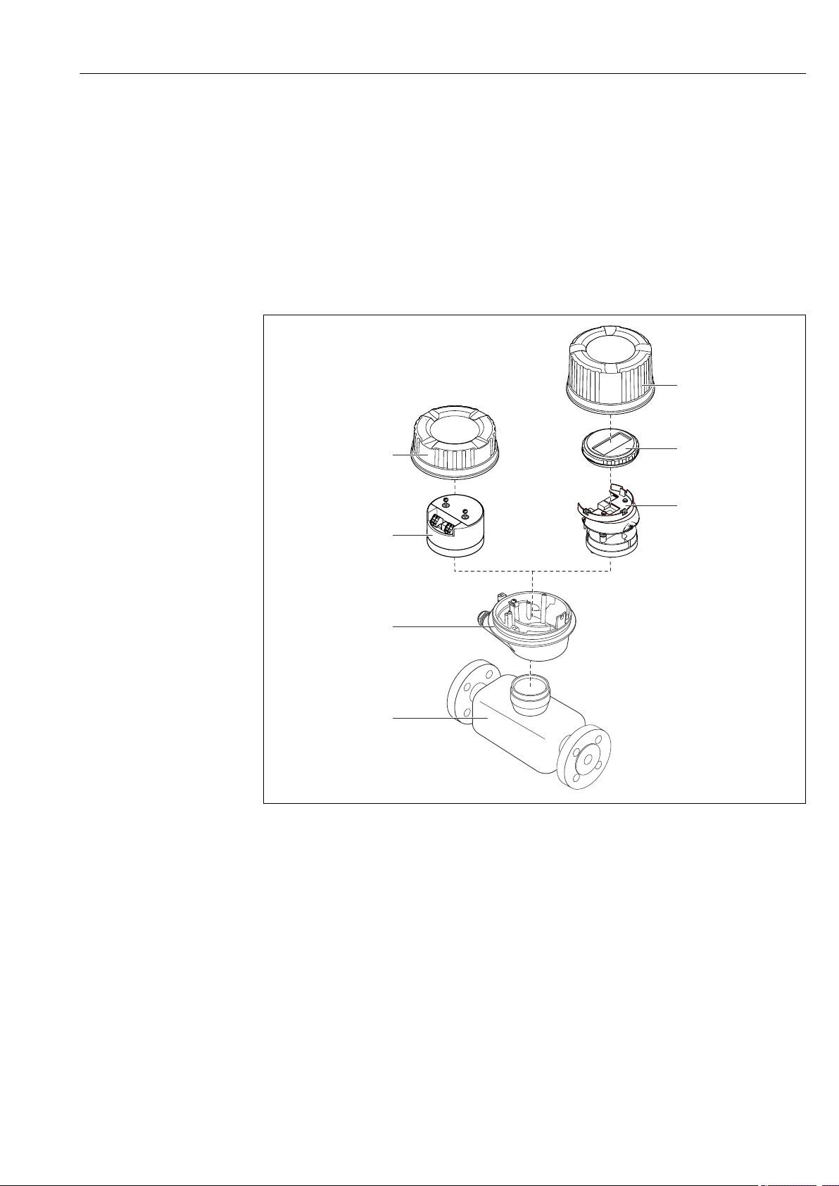
3 Product description
The device consists of a transmitter and a sensor.
The device is available as a compact version:
The transmitter and sensor form a mechanical unit.
3.1 Product design
3.1.1 Device version with HART communication type
A0023153
1 Important components of a measuring device
1 Sensor
2 Transmitter housing
3 Main electronics module
4 Transmitter housing cover
5 Transmitter housing cover (version for optional local display)
6 Local display (optional)
7 Main electronics module (with bracket for optional local display)
Endress+Hauser 11
Page 12
Incoming acceptance and product identification Proline Prosonic Flow E 100 HART
1
2
1
2
Order code:
Ser. no.:
Ext. ord. cd.:
i
i
Date:
4 Incoming acceptance and product
identification
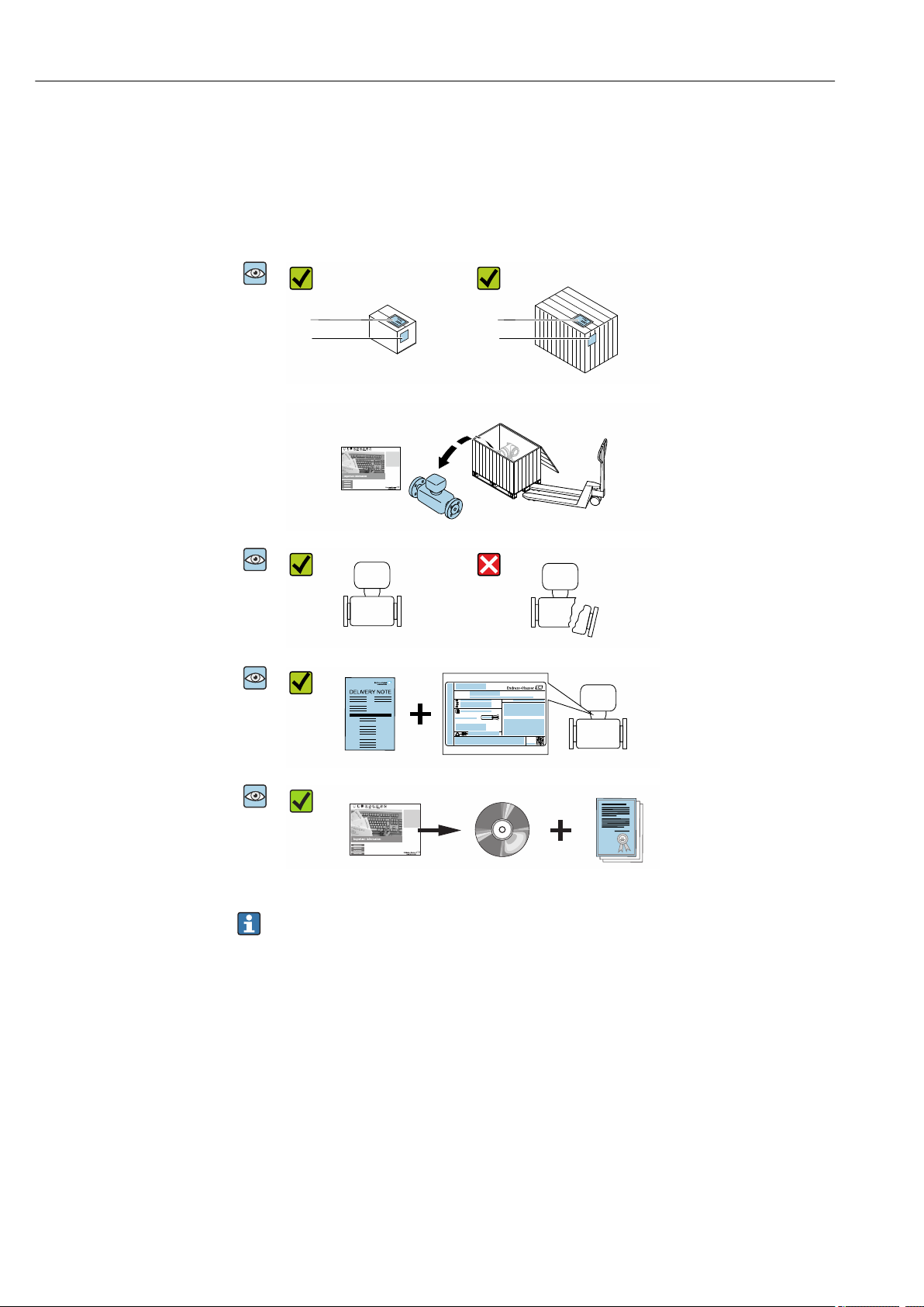
4.1 Incoming acceptance
Are the order codes on the
A0028673
delivery note (1) and the
product sticker (2) identical?
Are the goods undamaged?
A0028673
Do the nameplate data
A0028673
A0028673
match the ordering
information on the delivery
note?
Is the CD-ROM with the
Technical Documentation
(depends on device version)
and documents present?
• If one of the conditions is not satisfied, contact your Endress+Hauser Sales Center.
• Depending on the device version, the CD-ROM might not be part of the delivery!
The Technical Documentation is available via the Internet or via the Endress+Hauser
Operations App, see the "Product identification" section → 13.
4.2 Product identification
The following options are available for identification of the measuring device:
• Nameplate specifications
• Order code with breakdown of the device features on the delivery note
• Enter serial numbers from nameplates in W@M Device Viewer
(www.endress.com/deviceviewer): All information about the measuring device is
displayed.
• Enter the serial number from the nameplates into the Endress+Hauser Operations App
or scan the 2-D matrix code (QR code) on the nameplate with the Endress+Hauser
12 Endress+Hauser
Operations App: all the information for the measuring device is displayed.
Page 13
Proline Prosonic Flow E 100 HART Incoming acceptance and product identification
i
1
2
3
4
5
6
7
8
9
101112
Order code:
Ext. ord. cd.:
Ser. no.:
13
For an overview of the scope of the associated Technical Documentation, refer to the
following:
• The chapters "Additional standard documentation on the device" → 7 and
"Supplementary device-dependent documentation" → 7
• The W@M Device Viewer: Enter the serial number from the nameplate
(www.endress.com/deviceviewer)
• The Endress+Hauser Operations App: Enter the serial number from the nameplate or
scan the 2-D matrix code (QR code) on the nameplate.
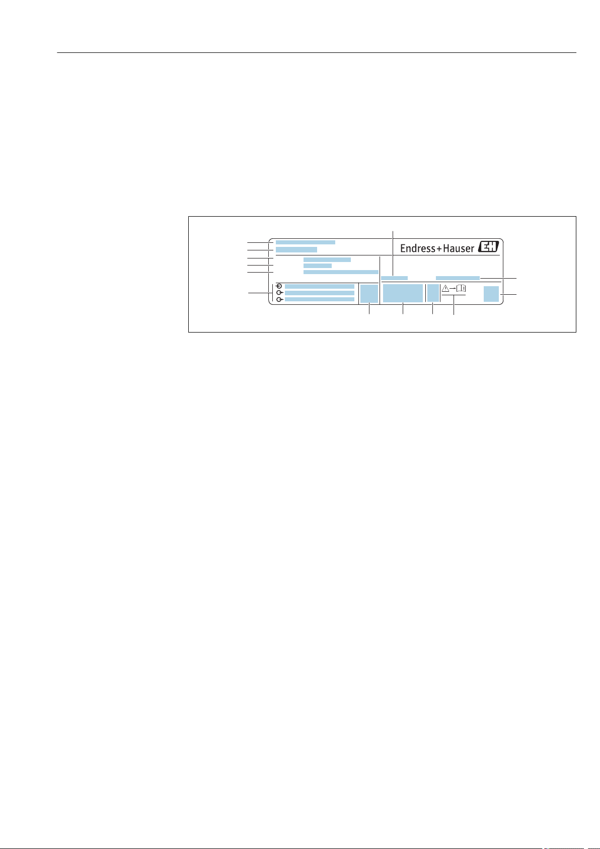
4.2.1 Transmitter nameplate
A0030222
2 Example of a transmitter nameplate
1 Manufacturing location
2 Name of the transmitter
3 Order code
4 Serial number (ser. no.)
5 Extended order code (Ext. ord. cd.)
6 Electrical connection data, e.g. available inputs and outputs, supply voltage
7 Permitted ambient temperature (Ta)
8 Degree of protection
9 2-D matrix code
10 Document number of safety-related supplementary documentation
11 Manufacturing date: year-month
12 CE mark, C-Tick
13 Firmware version (FW)
Endress+Hauser 13
Page 14
Incoming acceptance and product identification Proline Prosonic Flow E 100 HART
Date:
Size:
Material:
Tm:
Patents
i
Ptest =
i
Order code:
Ext. ord. cd.:
Ser. no.:
322541-0000
0044
11
1
2
3 4 5 6 7
12
8
9
13 14 15
16
17
19
18
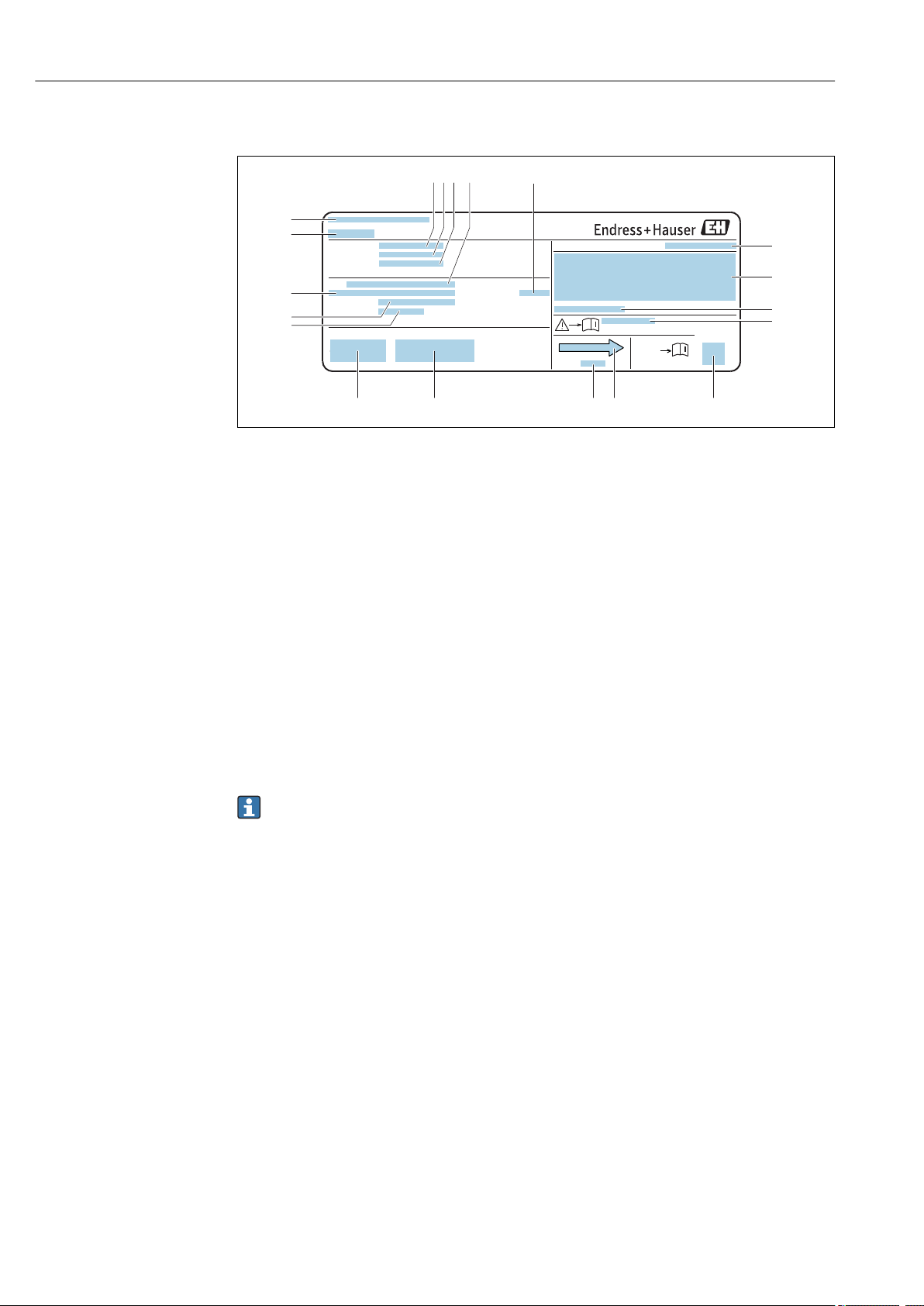
4.2.2 Sensor nameplate
A0013907
3 Example of a sensor nameplate
1 Manufacturing location
2 Name of the sensor
3 Order code
4 Serial number (ser. no.)
5 Extended order code (Ext. ord. cd.)
6 Nominal diameter of sensor
7 Test pressure of the sensor
8 Flange nominal diameter/nominal pressure
9 Material of measuring tube and manifold
10 Medium temperature range
11 CE mark, C-Tick
12 Additional information on version: certificates, approvals
13 Manufacturing date: year-month
14 Flow direction
15 2-D matrix code
16 Degree of protection
17 Approval information for explosion protection and Pressure Equipment Directive
18 Permitted ambient temperature (Ta)
19 Document number of safety-related supplementary documentation
Order code
The measuring device is reordered using the order code.
Extended order code
• The device type (product root) and basic specifications (mandatory features) are
always listed.
• Of the optional specifications (optional features), only the safety and approvalrelated specifications are listed (e.g. LA). If other optional specifications are also
ordered, these are indicated collectively using the # placeholder symbol (e.g. #LA#).
• If the ordered optional specifications do not include any safety and approval-related
specifications, they are indicated by the + placeholder symbol (e.g. XXXXXX-ABCDE
+).
14 Endress+Hauser
Page 15
Proline Prosonic Flow E 100 HART Storage and transport
5 Storage and transport
5.1 Storage conditions
Observe the following notes for storage:
Store in the original packaging to ensure protection from shock.
‣
Do not remove protective covers or protective caps installed on process connections.
‣
They prevent mechanical damage to the sealing surfaces and contamination in the
measuring tube.
Protect from direct sunlight to avoid unacceptably high surface temperatures.
‣
Store in a dry and dust-free place.
‣
Do not store outdoors.
‣
Storage temperature→ 96
5.2 Transporting the product
Transport the measuring device to the measuring point in the original packaging.
A0029252
Do not remove protective covers or caps installed on process connections. They
prevent mechanical damage to the sealing surfaces and contamination in the
measuring tube.
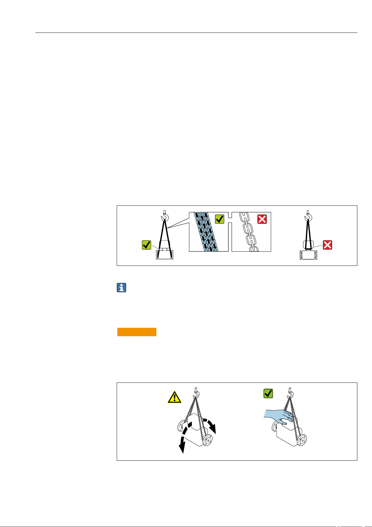
5.2.1 Measuring devices without lifting lugs
WARNING
L
Center of gravity of the measuring device is higher than the suspension points of the
webbing slings.
Risk of injury if the measuring device slips.
Secure the measuring device against slipping or turning.
‣
Observe the weight specified on the packaging (stick-on label).
‣
A0029214
Endress+Hauser 15
Page 16

Installation Proline Prosonic Flow E 100 HART
5.2.2 Measuring devices with lifting lugs
CAUTION
L
Special transportation instructions for devices with lifting lugs
Only use the lifting lugs fitted on the device or flanges to transport the device.
‣
The device must always be secured at two lifting lugs at least.
‣
5.2.3 Transporting with a fork lift
If transporting in wood crates, the floor structure enables the crates to be lifted lengthwise
or at both sides using a forklift.
5.3 Packaging disposal
All packaging materials are environmentally friendly and 100% recyclable:
• Measuring device secondary packaging: polymer stretch film that conforms to EC
Directive 2002/95/EC (RoHS).
• Packaging:
– Wood crate, treated in accordance with ISPM 15 standard, which is confirmed by the
affixed IPPC logo.
or
– Carton in accordance with European Packaging Directive 94/62EC; recyclability is
confirmed by the affixed RESY symbol.
• Seaworthy packaging (optional): Wood crate, treated in accordance with ISPM 15
standard, which is confirmed by the affixed IPPC logo.
• Carrying and mounting hardware:
– Disposable plastic pallet
– Plastic straps
– Plastic adhesive strips
• Dunnage: Paper cushion
6 Installation
6.1 Installation conditions
No special measures such as supports etc. are necessary. External forces are absorbed by
the construction of the device.
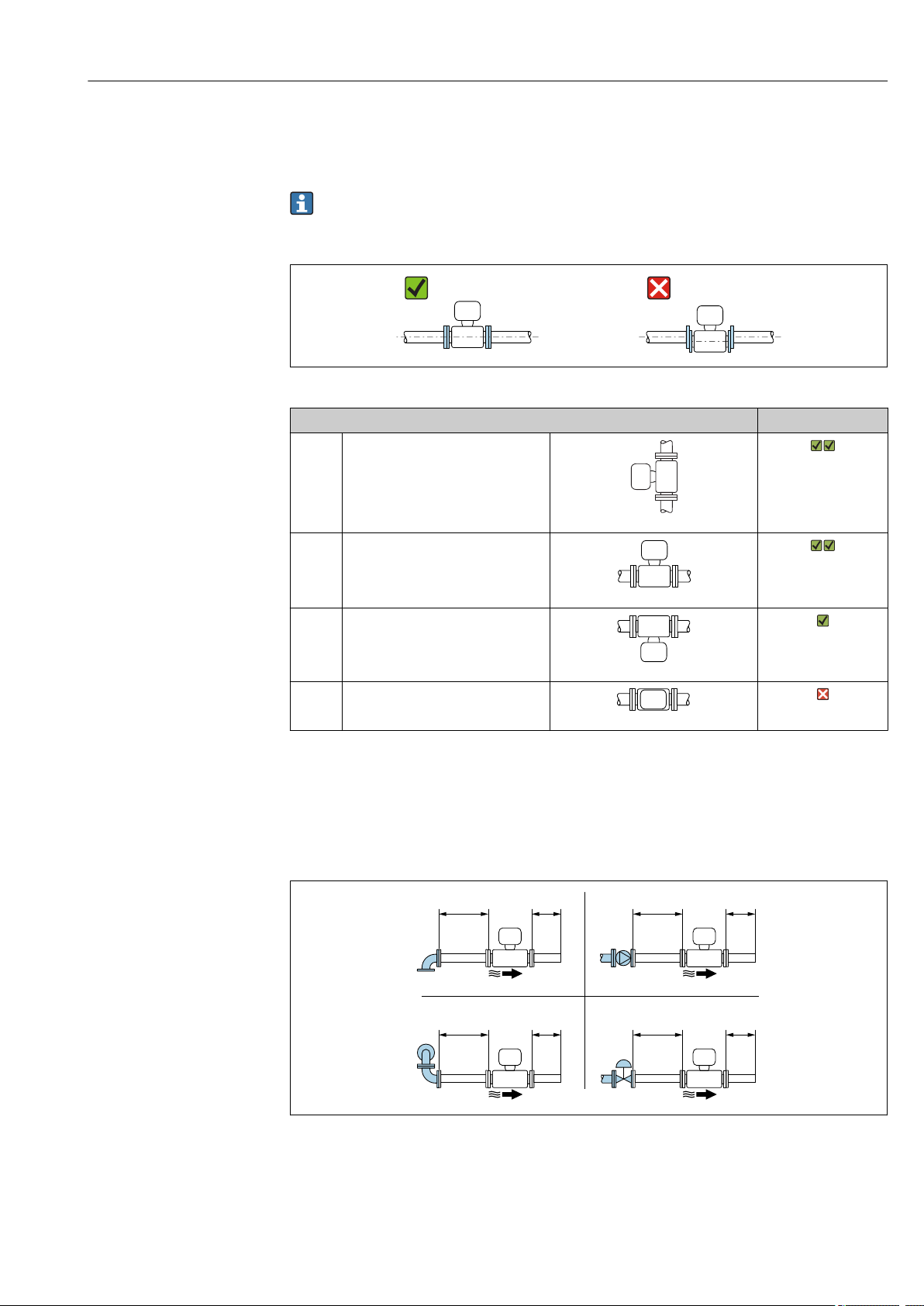
6.1.1 Mounting position
Mounting location
A0015543
16 Endress+Hauser
Page 17
Proline Prosonic Flow E 100 HART Installation
10 × DN 3 × DN
2
4
15 × DN 3 × DN
15 × DN 3 × DN10 × DN 3 × DN
Orientation
The direction of the arrow on the nameplate helps you to install the sensor according to
the flow direction (direction of medium flow through the piping).
• Install the measuring device in a parallel plane free of external mechanical stress.
• The internal diameter of the pipe must match the internal diameter of the sensor:
see the "Technical Information" device document, "Design and dimensions" section.
A0015895
Orientation Compact version
A Vertical orientation
A0015545
B Horizontal orientation, transmitter
head up
A0015589
C Horizontal orientation, transmitter
head down
A0015590
D Horizontal orientation, transmitter
head at side
A0015592
Inlet and outlet runs
If possible, the sensor should be installed upstream from valves, T-pieces, elbows etc. To
attain the specified level of accuracy of the measuring device, the below mentioned inlet
and outlet runs must be maintained at minimum. If there are several flow disturbances
present, the longest specified inlet run must be maintained.
Endress+Hauser 17
A0033877
4 Minimum inlet and outlet runs with various flow obstructions
1 90 ° elbow or T-section
2 Pump
3 2 × 90 ° elbow, 3-dimensional
4 Control valve
Page 18
Installation Proline Prosonic Flow E 100 HART
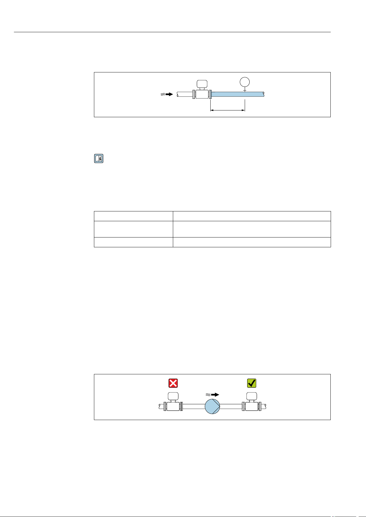
3…5 × DN
PT
Outlet runs when installing external devices
If installing an external device, observe the specified distance.
A0015901
PT Pressure
Installation dimensions
For the dimensions and installation lengths of the device, see the "Technical
Information" document, "Mechanical construction" section.
6.1.2 Requirements from environment and process
Ambient temperature range
Transmitter –25 to +60 °C (–13 to +140 °F)
Local display –20 to +60 °C (–4 to +140 °F), the readability of the display may be
impaired at temperatures outside the temperature range.
Sensor –25 to +60 °C (–13 to +140 °F)
If operating outdoors:
‣
Avoid direct sunlight, particularly in warm climatic regions.
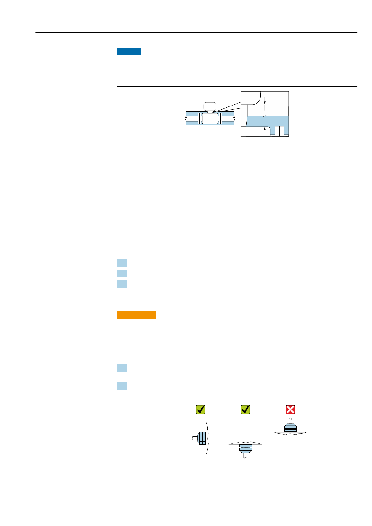
System pressure
It is important that cavitation does not occur, or that gases entrained in the liquids do not
outgas.
Cavitation is caused if the pressure drops below the vapor pressure:
In suction lines
Ensure the system pressure is sufficiently high to prevent cavitation and outgassing.
‣
For this reason, the following mounting locations are recommended:
• At the lowest point in a vertical pipe
• Downstream from pumps (no danger of vacuum)
A0028777
Thermal insulation
In the case of some fluids, it is important to keep the heat radiated from the sensor to the
transmitter to a low level. A wide range of materials can be used for the required
insulation.
18 Endress+Hauser
Page 19
Proline Prosonic Flow E 100 HART Installation
t
a
NOTICE
Electronics overheating on account of thermal insulation!
Observe maximum permitted insulation height of the transmitter neck so that the
‣
transmitter head is completely free.
A0034104
t Maximum insulation thickness 2 cm (0.79 in)
a Minimum distance from transmitter to insulation
6.2 Mounting the measuring device
6.2.1 Required tools
For sensor
For flanges and other process connections: Corresponding mounting tools
6.2.2 Preparing the measuring device
1. Remove all remaining transport packaging.
2. Remove any protective covers or protective caps present from the sensor.
3. Remove stick-on label on the electronics compartment cover.
6.2.3 Mounting the measuring device
WARNING
L
Danger due to improper process sealing!
Ensure that the inside diameters of the gaskets are greater than or equal to that of the
‣
process connections and piping.
Ensure that the gaskets are clean and undamaged.
‣
Install the gaskets correctly.
‣
1. Ensure that the direction of the arrow on the sensor matches the flow direction of
the medium.
2. Install the measuring device or turn the transmitter housing so that the cable entries
do not point upwards.
A0029263
Endress+Hauser 19
Page 20
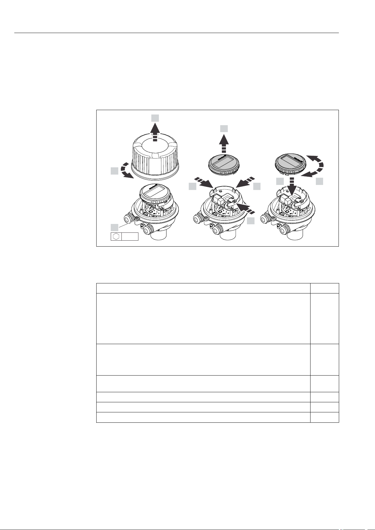
Installation Proline Prosonic Flow E 100 HART
1.
2.
3.
4.
5.
6.
7.
4.
4.
3 mm
6.2.4 Turning the display module
The local display is only available with the following device version:
Order code for "Display; Operation", option B: 4-line; lit, via communication
The display module can be turned to optimize display readability.
Aluminum housing version, AlSi10Mg, coated
A0023192
6.3 Post-mounting check
Is the device undamaged (visual inspection)?
Does the measuring device conform to the measuring point specifications?
For example:
• Process temperature
• Process pressure (refer to the section on "Pressure-temperature ratings" in the "Technical
Information" document)
• Ambient temperature range
• Measuring range
Has the correct orientation for the sensor been selected → 17?
• According to sensor type
• According to medium temperature
• According to medium properties (outgassing, with entrained solids)
Does the arrow on the sensor match the direction of flow of the medium through the piping
→ 17?
Are the measuring point identification and labeling correct (visual inspection)?
Is the device adequately protected from precipitation and direct sunlight?
Are the securing screw and securing clamp tightened securely?
20 Endress+Hauser
Page 21

Proline Prosonic Flow E 100 HART Electrical connection
7 Electrical connection
NOTICE
The measuring device does not have an internal circuit breaker.
For this reason, assign the measuring device a switch or power-circuit breaker so that
‣
the power supply line can be easily disconnected from the mains.
Although the measuring device is equipped with a fuse, additional overcurrent
‣
protection (maximum 16 A) should be integrated into the system installation.
7.1 Connection conditions
7.1.1 Required tools
• For cable entries: Use corresponding tools
• For securing clamp (on aluminum housing): Allen screw3 mm
• For securing screw (for stainless steel housing): open-ended wrench 8 mm
• Wire stripper
• When using stranded cables: crimper for wire end ferrule
7.1.2 Requirements for connecting cable
The connecting cables provided by the customer must fulfill the following requirements.
Electrical safety
In accordance with applicable federal/national regulations.
Permitted temperature range
• The installation guidelines that apply in the country of installation must be observed.
• The cables must be suitable for the minimum and maximum temperatures to be
expected.
Power supply cable
Standard installation cable is sufficient.
Signal cable
Current output 4 to 20 mA HART
A shielded cable is recommended. Observe grounding concept of the plant.
Pulse/frequency/switch output
Standard installation cable is sufficient.
Cable diameter
• Cable glands supplied:
M20 × 1.5 with cable ⌀ 6 to 12 mm (0.24 to 0.47 in)
• Spring terminals:
Wire cross-sections 0.5 to 2.5 mm2 (20 to 14 AWG)
Endress+Hauser 21
Page 22
Electrical connection Proline Prosonic Flow E 100 HART
L
L
26
27
+
_
24
25
1
2
+
_
+
_
1
2
3
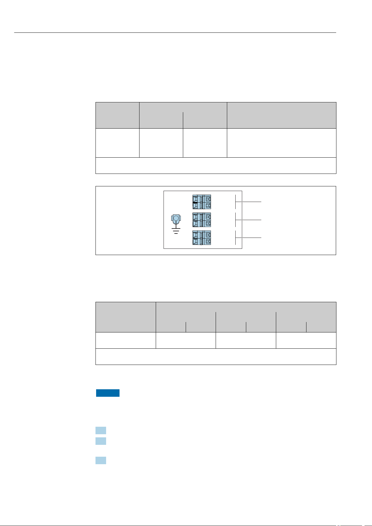
7.1.3 Terminal assignment
Transmitter
Connection version 4-20 mA HART with pulse/frequency/switch output
Order code for "Output", option B
Order code
"Housing"
Option A Terminals Terminals • Option A: coupling M20x1
Order code for "Housing":
Option A: compact, coated aluminum
5 Terminal assignment 4-20 mA HART with pulse/frequency/switch output
1 Power supply: DC 24 V
2 Output 1: 4-20 mA HART (active)
3 Output 2: pulse/frequency/switch output (passive)
Connection methods available
Outputs
Power
supply
Possible options for order code
"Electrical connection"
• Option B: thread M20x1
• Option C: thread G ½"
• Option D: thread NPT ½"
A0016888
Terminal number
Order code
"Output"
Option B DC 24 V 4-20 mA HART (active) Pulse/frequency/switch
Order code for "Output":
Option B: 4-20 mA HART with pulse/frequency/switch output
Power supply Output 1 Output 2
2 (L-) 1 (L+) 27 (–) 26 (+) 25 (–) 24 (+)
output (passive)
7.1.4 Preparing the measuring device
NOTICE
Insufficient sealing of the housing!
Operational reliability of the measuring device could be compromised.
Use suitable cable glands corresponding to the degree of protection.
‣
1. Remove dummy plug if present.
2. If the measuring device is supplied without cable glands:
Provide suitable cable gland for corresponding connecting cable.
3. If the measuring device is supplied with cable glands:
Observe requirements for connecting cables → 21.
22 Endress+Hauser
Page 23
Proline Prosonic Flow E 100 HART Electrical connection
1 2
A
7.2 Connecting the measuring device
NOTICE
Limitation of electrical safety due to incorrect connection!
Have electrical connection work carried out by appropriately trained specialists only.
‣
Observe applicable federal/national installation codes and regulations.
‣
Comply with local workplace safety regulations.
‣
The power unit must be tested to ensure it meets safety requirements (e.g. PELV,
‣
SELV).
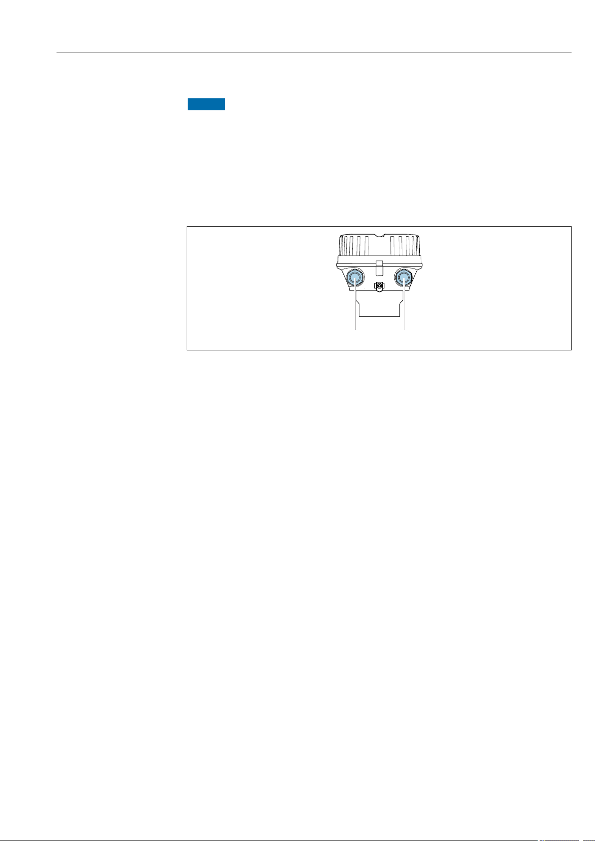
7.2.1 Connecting the transmitter
A Compact, coated aluminum
1 Cable entry for signal transmission
2 Cable entry for supply voltage
A0030221
Endress+Hauser 23
Page 24
Electrical connection Proline Prosonic Flow E 100 HART
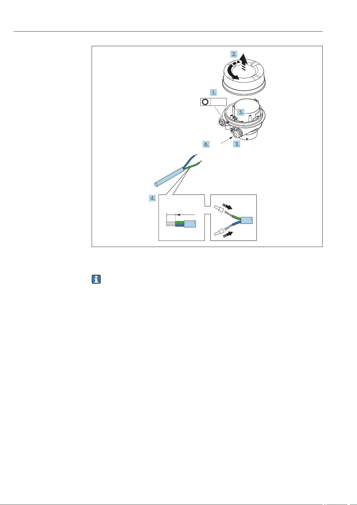
10 (0.4)
1
3 mm
6 Device version with connection example
1 Cable
Disconnect the local display from the main electronics module: Operating Instructions
for the device .
Connect the cable in accordance with the terminal assignment .
‣
7.2.2 Ensuring potential equalization
Requirements
No special measures for potential equalization are required.
A0033696
24 Endress+Hauser
Page 25
Proline Prosonic Flow E 100 HART Electrical connection
4
4...20 mA
5
2
1
3
6
1
2
3
12345
7.3 Special connection instructions
7.3.1 Connection examples
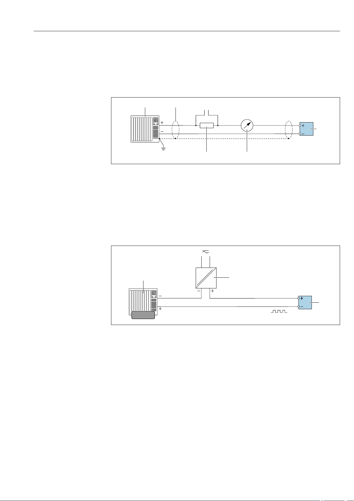
Current output 4 to 20 mA HART
A0029055
7 Connection example for 4 to 20 mA HART current output (active)
1 Automation system with current input (e.g. PLC)
2 Cable shield: the cable shield must be grounded at both ends to comply with EMC requirements; observe cable
specifications
3 Connection for HART operating devices → 35
4 Resistor for HART communication (≥ 250 Ω): observe maximum load
5 Analog display unit: observe maximum load
6 Transmitter
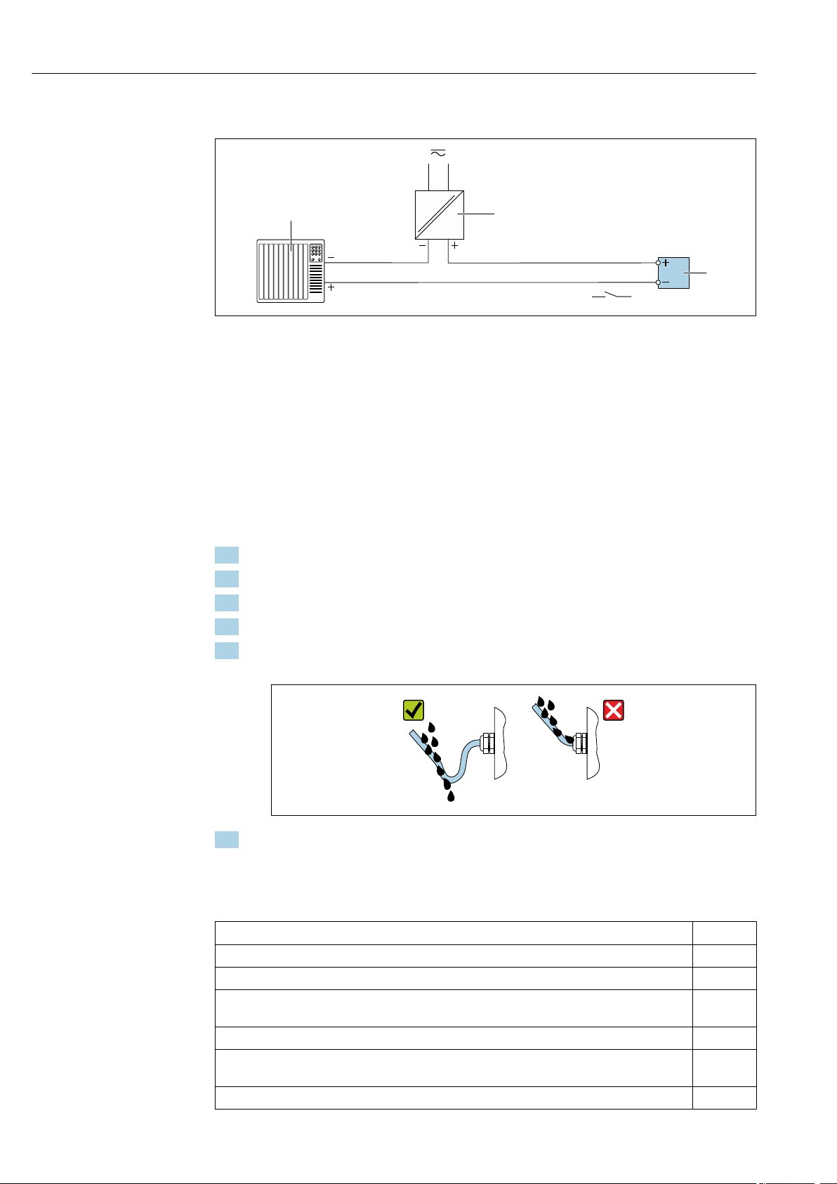
Pulse/frequency output
8 Connection example for pulse/frequency output (passive)
1 Automation system with pulse/frequency input (e.g. PLC)
2 Power supply
3 Transmitter: Observe input values
A0028761
Endress+Hauser 25
Page 26
Electrical connection Proline Prosonic Flow E 100 HART
1
2
3
Switch output
A0028760
9 Connection example for switch output (passive)
1 Automation system with switch input (e.g. PLC)
2 Power supply
3 Transmitter: Observe input values
7.4 Ensuring the degree of protection
The measuring device fulfills all the requirements for the IP66/67 degree of protection,
Type 4X enclosure.
To guarantee IP66/67 degree of protection, Type 4X enclosure, carry out the following
steps after the electrical connection:
1. Check that the housing seals are clean and fitted correctly.
2. Dry, clean or replace the seals if necessary.
3. Tighten all housing screws and screw covers.
4. Firmly tighten the cable glands.
5. To ensure that moisture does not enter the cable entry:
Route the cable so that it loops down before the cable entry ("water trap").
6. Insert dummy plugs into unused cable entries.
7.5 Post-connection check
A0029278
Are cables or the device undamaged (visual inspection)?
Do the cables used meet the requirements→ 21?
Do the cables have adequate strain relief?
Are all the cable glands installed, firmly tightened and leak-tight? Cable run with "water trap"
→ 26?
Does the supply voltage match the specifications on the transmitter nameplate → 94?
If supply voltage is present, is the power LED on the electronics module of the transmitter lit green
→ 11?
Depending on the device version, is the securing clamp or fixing screw firmly tightened?
26 Endress+Hauser
Page 27
Proline Prosonic Flow E 100 HART Operation options
1 2 3 4
8 Operation options
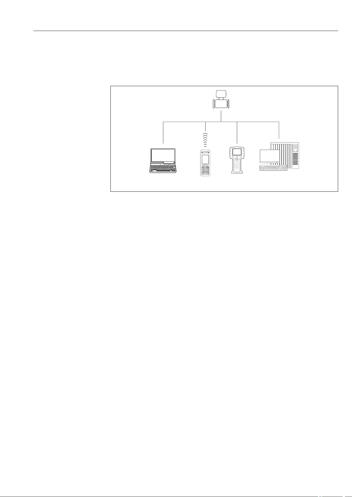
8.1 Overview of operating options
A0019598
1 Computer with Web browser (e.g. Internet Explorer) or with operating tool (e.g. FieldCare, AMS Device
Manager, SIMATIC PDM)
2 Field Xpert SFX350 or SFX370
3 Field Communicator 475
4 Control system (e.g. PLC)
Endress+Hauser 27
Page 28
Operation options Proline Prosonic Flow E 100 HART
!
Expert
System
Sensor
Communication
Application
Diagnostics
Access status display
Output
Operating menu for experts
Language
Operatation Language
Parameter 1
Setup
Submenu 1
Submenu n
Device tag
Advanced setup
Enter access code
Parameter 1
Parameter n
Submenu 1
Submenu n
Diagnostics
Parameter 1
Parameter n
Submenu 1
Submenu n
Operating menu for operators and maintenances
Parameter n
Operator
Maintenance
Task-oriented
Function-oriented
Expert
Wizard 1 / Parameter 1
Wizard n / Parameter n
Parameter n
Input
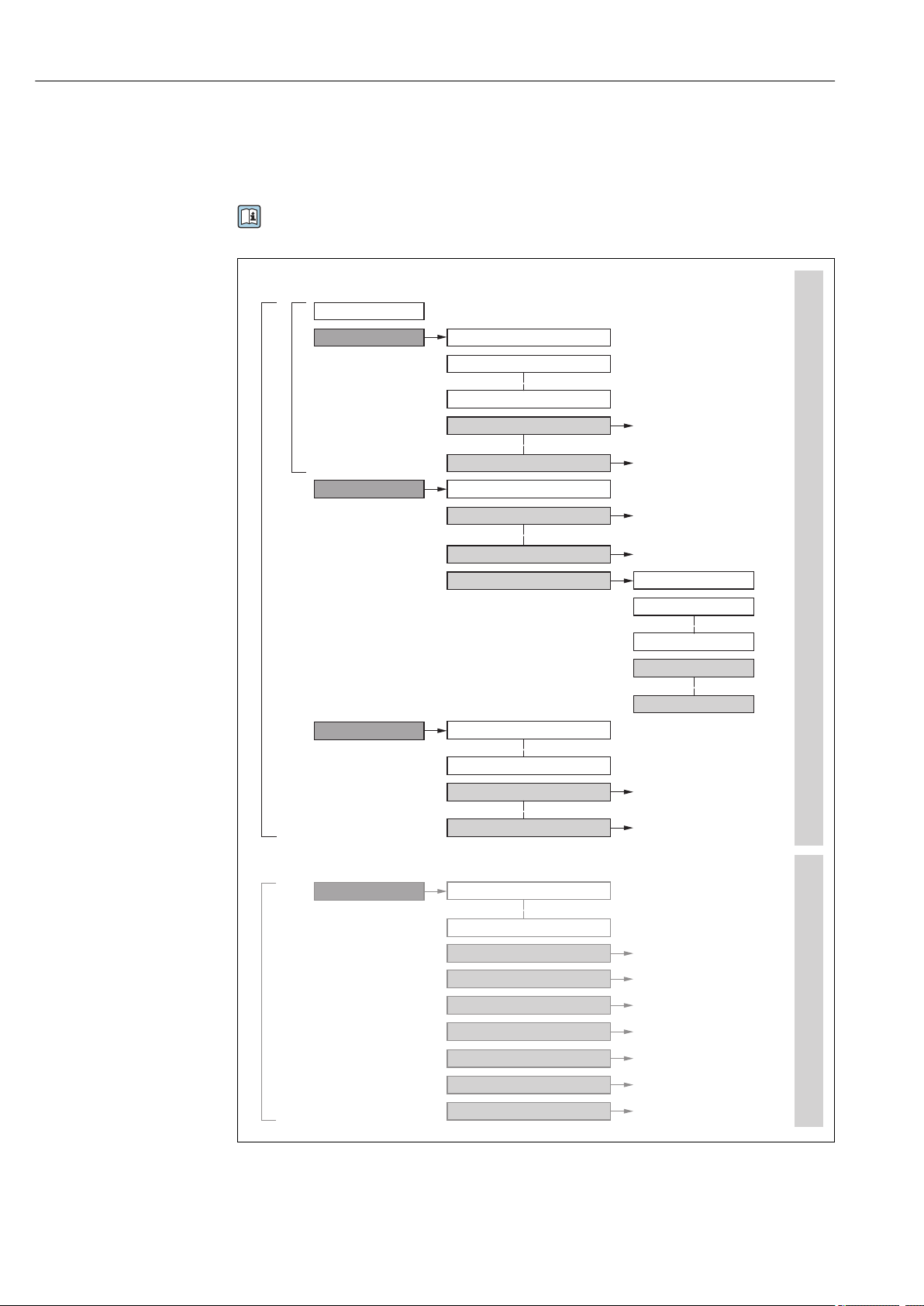
8.2 Structure and function of the operating menu
8.2.1 Structure of the operating menu
For an overview of the operating menu for experts: "Description of Device Parameters"
document supplied with the device
28 Endress+Hauser
10 Schematic structure of the operating menu
A0018237-EN
Page 29

Proline Prosonic Flow E 100 HART Operation options
8.2.2 Operating philosophy
The individual parts of the operating menu are assigned to certain user roles (operator,
maintenance etc.). Each user role contains typical tasks within the device lifecycle.
Menu/parameter User role and tasks Content/meaning
Language task-oriented Role "Operator", "Maintenance"
Tasks during operation:
• Configuring the operational display
Operation • Configuring the operational display (e.g. display format, display contrast)
Setup "Maintenance" role
Diagnostics "Maintenance" role
• Reading measured values
Commissioning:
• Configuration of the measurement
• Configuration of the outputs
Fault elimination:
• Diagnostics and elimination of
process and device errors
• Measured value simulation
• Defining the operating language
• Defining the Web server operating language
• Resetting and controlling totalizers
• Resetting and controlling totalizers
Submenus for fast commissioning:
• Set the system units
• Configure the outputs
• Configuring the operational display
• Define the output conditioning
• Set the low flow cut off
Advanced setup
• For more customized configuration of the measurement (adaptation to
special measuring conditions)
• Configuration of totalizers
• Configure the WLAN settings
• Administration (define access code, reset measuring device)
Contains all parameters for error detection and analyzing process and
device errors:
• Diagnostic list
Contains up to 5 currently pending diagnostic messages.
• Event logbook
Contains event messages that have occurred.
• Device information
Contains information for identifying the device.
• Measured values
Contains all current measured values.
• Heartbeat
The functionality of the device is checked on demand and the verification
results are documented.
• Simulation
Is used to simulate measured values or output values.
Expert function-oriented Tasks that require detailed
knowledge of the function of the
device:
• Commissioning measurements
under difficult conditions
• Optimal adaptation of the
measurement to difficult
conditions
• Detailed configuration of the
communication interface
• Error diagnostics in difficult cases
Contains all the parameters of the device and makes it possible to access
these parameters directly using an access code. The structure of this menu is
based on the function blocks of the device:
• System
Contains all higher-order device parameters which do not concern the
measurement or the communication interface.
• Sensor
Configuration of the measurement.
• Output
Configuring of the analog current outputs as well as the pulse/frequency
and switch output.
• Communication
Configuration of the digital communication interface and the Web server.
• Application
Configure the functions that go beyond the actual measurement (e.g.
totalizer).
• Diagnostics
Error detection and analysis of process and device errors and for device
simulation and Heartbeat Technology.
Endress+Hauser 29
Page 30

Operation options Proline Prosonic Flow E 100 HART
8.3 Access to the operating menu via the web browser
8.3.1 Function range
Thanks to the integrated Web server, the device can be operated and configured via a Web
browser and via a service interface (CDI-RJ45) . In addition to the measured values, status
information on the device is also displayed and allows the user to monitor the status of the
device. Furthermore the device data can be managed and the network parameters can be
configured.
For additional information on the Web server, refer to the Special Documentation for
the device
8.3.2 Prerequisites
Computer hardware
Interface The computer must have an RJ45 interface.
Connection Standard Ethernet cable with RJ45 connector.
Screen Recommended size: ≥12" (depends on the screen resolution)
Computer software
Recommended operating
systems
Web browsers supported • Microsoft Internet Explorer 8 or higher
Microsoft Windows 7 or higher.
Microsoft Windows XP is supported.
• Microsoft Edge
• Mozilla Firefox
• Google Chrome
• Safari
Computer settings
User rights Appropriate user rights (e.g. administrator rights) for TCP/IP and proxy server
settings are necessary (for adjusting the IP address, subnet mask etc.).
Proxy server settings of the
Web browser
JavaScript JavaScript must be enabled.
Network connections Only the active network connections to the measuring device should be used.
The Web browser setting Use a Proxy Server for Your LAN must be
deselected .
If JavaScript cannot be enabled:
enter http://XXX.XXX.X.XXX/basic.html in the address line of the Web
browser, e.g. http://192.168.1.212/basic.html. A fully functional but
simplified version of the operating menu structure starts in the Web
browser.
Switch off all other network connections such as WLAN.
In the event of connection problems: → 72
30 Endress+Hauser
Page 31

Proline Prosonic Flow E 100 HART Operation options
ON OFF
1 = Write protection
2 =
Default Ethernet
network settings
Measuring device: Via CDI-RJ45 service interface
Device CDI-RJ45 service interface
Measuring device The measuring device has an RJ45 interface.
Web server Web server must be enabled; factory setting: ON
For information on enabling the Web server → 34
IP address Default settings:
• IP address: 192.168.1.212
• Set DIP switch No. 2 = OFF
If the IP address was changed manually or the address assigned via DHCP, the
address can no longer be read from the device. To ensure however that a
connection can still be established with the measuring device, DIP switch no. 2
must be set from OFF → ON and the device restarted. The IP address is now
temporarily 192.168.1.212 once again.
If the original setting is to be restored, DIP switch no. 2 must be set from ON
→ OFF and the device restarted.
8.3.3 Establishing a connection
Via service interface (CDI-RJ45)
Preparing the measuring device
Configuring the Internet protocol of the computer
The following information refers to the default Ethernet settings of the device.
IP address of the device: 192.168.1.212 (factory setting)
1. Switch on the measuring device.
2. Connect to the computer using a cable → 102.
3. If a 2nd network card is not used, close all the applications on the notebook.
Applications requiring Internet or a network, such as e-mail, SAP applications,
Internet or Windows Explorer.
4. Close any open Internet browsers.
5. Configure the properties of the Internet protocol (TCP/IP) as defined in the table:
IP address 192.168.1.XXX; for XXX all numerical sequences except: 0, 212 and 255 → e.g.
192.168.1.213
Subnet mask 255.255.255.0
Default gateway 192.168.1.212 or leave cells empty
A0035277
Starting the Web browser
1. Start the Web browser on the computer.
Endress+Hauser 31
Page 32

Operation options Proline Prosonic Flow E 100 HART
6
7
8
9
10
1 52 3 4
2. Enter the IP address of the Web server in the address line of the Web browser:
192.168.1.212
The login page appears.
A0029417
1 Picture of device
2 Device name
3 Device tag (→ 44)
4 Status signal
5 Current measured values
6 Operating language
7 User role
8 Access code
9 Login
10 Reset access code (→ 63)
If a login page does not appear, or if the page is incomplete → 72
8.3.4 Logging on
1. Select the preferred operating language for the Web browser.
2. Enter the user-specific access code.
3. Press OK to confirm your entry.
Access code 0000 (factory setting); can be changed by customer
If no action is performed for 10 minutes, the Web browser automatically returns to
the login page.
32 Endress+Hauser
Page 33

Proline Prosonic Flow E 100 HART Operation options
6
1 2 3 4 5
7
8.3.5 User interface
A0032879
1 Picture of device
2 Device name
3 Device tag
4 Status signal
5 Current measured values
6 Navigation area
7 Local display language
Header
The following information appears in the header:
• Device name
• Device tag
• Device status with status signal → 74
• Current measured values
Function row
Functions Meaning
Measured values Displays the measured values of the measuring device
• Access to the operating menu from the measuring device
Menu
• The structure of the operating menu is the same as for the operating tools
Device status Displays the diagnostic messages currently pending, listed in order of priority
Data exchange between PC and measuring device:
• Device configuration:
Data
management
Network
configuration
Logout End the operation and call up the login page
• Logbook - Export Event logbook (.csv file)
• Documents - Export documents:
Configuration and checking of all the parameters required for establishing the connection
to the measuring device:
• Network settings (e.g. IP address, MAC address)
• Device information (e.g. serial number, firmware version)
For detailed information on the structure of the operating menu, see the Operating
Instructions for the measuring device
– Load settings from the device
(XML format, save configuration)
– Save settings to the device
(XML format, restore configuration)
– Export backup data record
(.csv file, create documentation of the measuring point configuration)
– Verification report
(PDF file, only available with the "Heartbeat Verification" application package)
Endress+Hauser 33
Page 34

Operation options Proline Prosonic Flow E 100 HART
Navigation area
If a function is selected in the function bar, the submenus of the function open in the
navigation area. The user can now navigate through the menu structure.
Working area
Depending on the selected function and the related submenus, various actions can be
performed in this area:
• Configuring parameters
• Reading measured values
• Calling up help text
• Starting an upload/download
8.3.6 Disabling the Web server
The Web server of the measuring device can be switched on and off as required using the
Web server functionality parameter.
Navigation
"Expert" menu → Communication → Web server
Parameter overview with brief description
Parameter Description Selection Factory setting
Web server functionality Switch the Web server on and off. • Off
• HTML Off
• On
Function scope of the "Web server functionality" parameter
Option Description
Off • The web server is completely disabled.
• Port 80 is locked.
HTML Off The HTML version of the web server is not available.
On • The complete functionality of the web server is available.
• JavaScript is used.
• The password is transferred in an encrypted state.
• Any change to the password is also transferred in an encrypted state.
Enabling the Web server
If the Web server is disabled it can only be re-enabled with the Web server functionality
parameter via the following operating options:
• Via Bedientool "FieldCare"
• Via "DeviceCare" operating tool
On
8.3.7 Logging out
Before logging out, perform a data backup via the Data management function
(upload configuration from device) if necessary.
1. Select the Logout entry in the function row.
The home page with the Login box appears.
2. Close the Web browser.
34 Endress+Hauser
Page 35

Proline Prosonic Flow E 100 HART Operation options
1 2 3 5
7
4 6
+
E
–
12
3
3. If no longer needed:
Reset modified properties of the Internet protocol (TCP/IP) → 31.
8.4 Access to the operating menu via the operating tool
8.4.1 Connecting the operating tool
Via HART protocol
11 Options for remote operation via HART protocol
1 Control system (e.g. PLC)
2 Field Communicator 475
3 Computer with operating tool (e.g. FieldCare, AMS Device Manager, SIMATIC PDM)
4 Commubox FXA195 (USB)
5 Field Xpert SFX350 or SFX370
6 VIATOR Bluetooth modem with connecting cable
7 Transmitter
Via service interface (CDI)
A0016948
Endress+Hauser 35
1 Service interface (CDI = Endress+Hauser Common Data Interface) of the measuring device
2 Commubox FXA291
3 Computer with FieldCare operating tool with COM DTM CDI Communication FXA291
Via service interface (CDI-RJ45)
A0014019
Page 36

Operation options Proline Prosonic Flow E 100 HART
1
2
3
HART
A0016926
12 Connection for the order code for "Output", option B: 4-20 mA HART, pulse/frequency/switch output
1 Service interface (CDI -RJ45) of the measuring device with access to the integrated Web server
2 Computer with Web browser (e.g. Internet Explorer) for accessing the integrated device Web server or with
"FieldCare" operating tool with COM DTM "CDI Communication TCP/IP"
3 Standard Ethernet connecting cable with RJ45 plug
8.4.2 Field Xpert SFX350, SFX370
Function range
Field Xpert SFX350 and Field Xpert SFX370 are mobile computers for commissioning and
maintenance. They enable efficient device configuration and diagnostics for HART and
FOUNDATION Fieldbus devices in the non-hazardous area (SFX350, SFX370) and
hazardous area (SFX370).
For details, see Operating Instructions BA01202S
Source for device description files
See information → 39
8.4.3 FieldCare
Function scope
FDT-based plant asset management tool from Endress+Hauser. It can configure all smart
field devices in a system and helps you manage them. By using the status information, it is
also a simple but effective way of checking their status and condition.
Access is via:
• HART protocol
• CDI-RJ45 service interface
Typical functions:
• Configuring parameters of transmitters
• Loading and saving device data (upload/download)
• Documentation of the measuring point
• Visualization of the measured value memory (line recorder) and event logbook
For additional information about FieldCare, see Operating Instructions BA00027S
and BA00059S
Source for device description files
See information → 39
36 Endress+Hauser
Page 37

Proline Prosonic Flow E 100 HART Operation options
6
5
32
1
Xxxxxx/…/…/
7
P
P
+
–
P
–
P
+
+
+
+
+
+
4
8 9
10
11
Xxxxxxx
GoodStatus:
Device tag:
Xxxxxxx
Device name:
Mass flow:
12.34
kg/h
Volume flow:
12.34
m /h³
Mass flow unit:
Volume flow unit:
kg/h
m /h³
Access status tooling
Operation
Setup
Xxxxxx
Mass flow unit
Volume flow unit
Select medium
Device tag
…
…
Advanced setup
Diagnostics
Expert
Maintenance
kg/h
m /h³
Xxxxxx
System units
Establishing a connection
1. Start FieldCare and launch the project.
2. In the network: Add a device.
The Add device window opens.
3. Select the CDI Communication TCP/IP option from the list and press OK to confirm.
4. Right-click CDI Communication TCP/IP and select the Add device option in the
context menu that opens.
5. Select the desired device from the list and press OK to confirm.
The CDI Communication TCP/IP (Configuration) window opens.
6. Enter the device address in the IP address field and press Enter to confirm:
192.168.1.212 (factory setting); if the IP address is not known .
7. Establish the online connection to the device.
For additional information, see Operating Instructions BA00027S and BA00059S
User interface
1 Header
2 Picture of device
3 Device name
4 Tag name
5 Status area with status signal→ 74
6 Display area for current measured values
7 Edit toolbar with additional functions such as save/restore, event list and create documentation
8 Navigation area with operating menu structure
9 Working area
10 Range of action
11 Status area
Endress+Hauser 37
A0021051-EN
Page 38

Operation options Proline Prosonic Flow E 100 HART
8.4.4 DeviceCare
Function scope
Tool to connect and configure Endress+Hauser field devices.
The fastest way to configure Endress+Hauser field devices is with the dedicated
"DeviceCare" tool. Together with the device type managers (DTMs) it presents a convenient,
comprehensive solution.
For details, see Innovation Brochure IN01047S
Source for device description files
See information → 39
8.4.5 AMS Device Manager
Function scope
Program from Emerson Process Management for operating and configuring measuring
devices via HART protocol.
Source for device description files
See data → 39
8.4.6 SIMATIC PDM
Function scope
SIMATIC PDM is a standardized, manufacturer-independent program from Siemens for
the operation, configuration, maintenance and diagnosis of intelligent field devices via
HART protocol.
Source for device description files
See data → 39
8.4.7 Field Communicator 475
Function scope
Industrial handheld terminal from Emerson Process Management for remote
configuration and measured value display via HART protocol.
Source for device description files
See data → 39
38 Endress+Hauser
Page 39

Proline Prosonic Flow E 100 HART System integration
9 System integration
9.1 Overview of device description files
9.1.1 Current version data for the device
Firmware version 01.00.zz • On the title page of the Operating Instructions
• On the transmitter nameplate → 12
• Firmware version
Diagnostics → Device information → Firmware
version
Release date of firmware version 12.2017 ---
Manufacturer ID 0x11 Manufacturer ID
Diagnostics → Device information → Manufacturer ID
Device type ID 0x5c Device type
Diagnostics → Device information → Device type
HART protocol revision 7 ---
Device revision 1 • On the transmitter nameplate → 12
• Device revision
Diagnostics → Device information → Device revision
For an overview of the different firmware versions for the device → 85
9.1.2 Operating tools
The suitable device description file for the individual operating tools is listed in the table
below, along with information on where the file can be acquired.
Operating tool via
HART protocol
FieldCare • www.endress.com → Download Area
DeviceCare • www.endress.com → Download Area
• Field Xpert SFX350
• Field Xpert SFX370
AMS Device Manager
(Emerson Process Management)
SIMATIC PDM
(Siemens)
Field Communicator 475
(Emerson Process Management)
Sources for obtaining device descriptions
• CD–ROM (contact Endress+Hauser)
• DVD (contact Endress+Hauser)
• CD–ROM (contact Endress+Hauser)
• DVD (contact Endress+Hauser)
Use update function of handheld terminal
www.endress.com → Download Area
www.endress.com → Download Area
Use update function of handheld terminal
9.2 Measured variables via HART protocol
The following measured variables (HART device variables) are assigned to the dynamic
variables at the factory:
Endress+Hauser 39
Page 40

System integration Proline Prosonic Flow E 100 HART
Dynamic variables Measured variables
(HART device variables)
Primary dynamic variable (PV) Volume flow
Secondary dynamic variable (SV) Totalizer 1
Tertiary dynamic variable (TV) Totalizer 2
Quaternary dynamic variable (QV) Totalizer 3
The assignment of the measured variables to the dynamic variables can be modified and
assigned as desired via the operating tool using the following parameters:
• Expert → Communication → HART output → Output → Assign PV
• Expert → Communication → HART output → Output → Assign SV
• Expert → Communication → HART output → Output → Assign TV
• Expert → Communication → HART output → Output → Assign QV
The following measured variables can be assigned to the dynamic variables:
Measured variables for PV (primary dynamic variable)
• Off
• Volume flow
• Mass flow
• Sound velocity
• Flow velocity
• Temperature
• Acceptance rate
• Signal strength
• Signal to noise ratio
• Turbulence
• Signal asymmetry
Measured variables for SV, TV, QV (secondary, tertiary and quaternary dynamic
variable)
• Volume flow
• Mass flow
• Flow velocity
• Sound velocity
• Temperature
• Signal strength
• Signal to noise ratio
• Turbulence
• Acceptance rate
• Signal asymmetry
• Totalizer 1
• Totalizer 2
• Totalizer 3
9.3 Other settings
Burst mode functionality in accordance with HART 7 Specification:
40 Endress+Hauser
Page 41

Proline Prosonic Flow E 100 HART System integration
Navigation
"Expert" menu → Communication → HART output → Burst configuration → Burst
configuration 1 to n
Burst configuration
‣
Burst configuration 1 to n
‣
Burst mode 1 to n
Burst command 1 to n
Burst variable 0
Burst variable 1
Burst variable 2
Burst variable 3
Burst variable 4
Burst variable 5
Burst variable 6
Burst variable 7
Burst trigger mode
→ 41
→ 41
→ 42
→ 42
→ 42
→ 42
→ 42
→ 42
→ 42
→ 42
→ 42
Parameter overview with brief description
Parameter Description Selection / User entry Factory setting
Burst mode 1 to n Activate the HART burst mode for burst
message X.
Burst command 1 to n Select the HART command that is sent to the
HART master.
Burst trigger level
Min. update period
Max. update period
• Off
• On
• Command 1
• Command 2
• Command 3
• Command 9
• Command 33
• Command 48
→ 42
→ 42
→ 42
Off
Command 2
Endress+Hauser 41
Page 42

System integration Proline Prosonic Flow E 100 HART
Parameter Description Selection / User entry Factory setting
Burst variable 0 For HART command 9 and 33: select the
HART device variable or the process variable.
Burst variable 1 For HART command 9 and 33: select the
HART device variable or the process variable.
Burst variable 2 For HART command 9 and 33: select the
HART device variable or the process variable.
Burst variable 3 For HART command 9 and 33: select the
HART device variable or the process variable.
Burst variable 4 For HART command 9: select the HART
device variable or the process variable.
Burst variable 5 For HART command 9: select the HART
device variable or the process variable.
Burst variable 6 For HART command 9: select the HART
device variable or the process variable.
Burst variable 7 For HART command 9: select the HART
device variable or the process variable.
Burst trigger mode Select the event that triggers burst messageX.• Continuous
Burst trigger level Enter the burst trigger value.
Together with the option selected in the
Burst trigger mode parameter the burst
trigger value determines the time of burst
message X.
Min. update period Enter the minimum time span between two
burst commands of burst message X.
Max. update period Enter the maximum time span between two
burst commands of burst message X.
• Volume flow
Volume flow
• Mass flow
• Flow velocity
• Temperature
• Sound velocity
• Signal asymmetry
• Acceptance rate
• Turbulence
• Signal strength
• Signal to noise ratio
*
*
*
*
*
• Totalizer 1
• Totalizer 2
• Totalizer 3
• Percent of range
• Measured current
• Primary variable (PV)
• Secondary variable (SV)
• Tertiary variable (TV)
• Quaternary variable (QV)
• Not used
See the Burst variable 0
Not used
parameter.
See the Burst variable 0
Not used
parameter.
See the Burst variable 0
Not used
parameter.
See the Burst variable 0
Not used
parameter.
See the Burst variable 0
Not used
parameter.
See the Burst variable 0
Not used
parameter.
See the Burst variable 0
Not used
parameter.
Continuous
• Window
• Rising
• Falling
• On change
Signed floating-point number –
Positive integer 1 000 ms
Positive integer 2 000 ms
* Visibility depends on order options or device settings
42 Endress+Hauser
Page 43

Proline Prosonic Flow E 100 HART Commissioning
10 Commissioning
10.1 Function check
Before commissioning the measuring device:
Make sure that the post-installation and post-connection checks have been performed.
‣
• "Post-installation check" checklist→ 20
• "Post-connection check" checklist → 26
10.2 Switching on the measuring device
After a successful function check, switch on the measuring device.
‣
After a successful startup, the local display switches automatically from the startup
display to the operational display.
If nothing appears on the local display or a diagnostic message is displayed, refer to
the section on "Diagnostics and troubleshooting" → 72.
10.3 Setting the operating language
Factory setting: English or ordered local language
The operating language can be set in FieldCare, DeviceCare or via the Web server:
Operation → Display language
10.4 Configuring the measuring device
The Setup menu with its submenus contains all the parameters needed for standard
operation.
Setup
Device tag
System units
‣
Current output 1
‣
Pulse/frequency/switch output 1
‣
Low flow cut off
‣
→ 44
→ 44
→ 46
→ 47
→ 56
Advanced setup
‣
→ 57
10.4.1 Defining the tag name
To enable fast identification of the measuring point within the system, you can enter a
unique designation using the Device tag parameter and thus change the factory setting.
Enter the tag name in the "FieldCare" operating tool → 37
Endress+Hauser 43
Page 44

Commissioning Proline Prosonic Flow E 100 HART
Navigation
"Setup" menu → Device tag
Parameter overview with brief description
Parameter Description User entry Factory setting
Device tag Enter the name for the measuring point. Max. 32 characters, such as
letters, numbers or special
characters (e.g. @, %, /).
Prosonic Flow E 100
10.4.2 Setting the system units
In the System units submenu the units of all the measured values can be set.
Navigation
"Setup" menu → System units
System units
‣
Volume flow unit
Volume unit
Mass flow unit
Mass unit
Temperature unit
Length unit
Velocity unit
Parameter overview with brief description
Parameter Description Selection Factory setting
Volume flow unit Select volume flow unit.
Result
The selected unit applies for:
• Output
• Low flow cut off
• Simulation process variable
Volume unit Select volume unit. Unit choose list Country-specific:
Mass flow unit Select mass flow unit.
Result
The selected unit applies for:
• Output
• Low flow cut off
• Simulation process variable
Unit choose list Country-specific:
• m³/h
• ft³/min
• dm³
• ft³
Unit choose list Country-specific:
• kg/h
• lb/min
→ 44
→ 44
→ 44
→ 45
→ 45
→ 45
→ 45
44 Endress+Hauser
Page 45

Proline Prosonic Flow E 100 HART Commissioning
Parameter Description Selection Factory setting
Mass unit Select mass unit. Unit choose list Country-specific:
• kg
• lb
Temperature unit Select temperature unit.
Result
The selected unit applies for:
• Temperature
• Maximum value
• Minimum value
• Maximum value
• Minimum value
Length unit Select length unit for nominal diameter. Unit choose list Country-specific:
Velocity unit Select velocity unit.
Result
The selected unit applies for:
• Flow velocity
• Sound velocity
• Maximum value
• Minimum value
• Maximum value
• Minimum value
Unit choose list Country-specific:
• °C
• °F
• mm
• in
Unit choose list Country-specific:
• m/s
• ft/s
Endress+Hauser 45
Page 46

Commissioning Proline Prosonic Flow E 100 HART
10.4.3 Configuring the current output
The Current output submenu guides you systematically through all the parameters that
have to be set for configuring the current output.
Navigation
"Setup" menu → Current output 1
Structure of the submenu
Current output 1
‣
Assign current output 1
Current span
0/4 mA value
20 mA value
Fixed current
Damping output 1
Failure mode
Failure current
Parameter overview with brief description
Parameter Prerequisite Description Selection / User
Assign current output 1 – Select process variable for
current output.
Current span – Select current range for
process value output and
upper/lower level for alarm
signal.
0/4 mA value One of the following options is
selected in the Current span
parameter (→ 46):
• 4...20 mA NAMUR
• 4...20 mA US
• 4...20 mA
• 0...20 mA
Enter 4 mA value. Signed floating-point
entry
• Off
• Volume flow
• Mass flow
• Sound velocity
• Flow velocity
• Temperature
• Acceptance rate
• Signal strength
• Signal to noise
ratio
• Turbulence
• Signal asymmetry
• 4...20 mA NAMUR
• 4...20 mA US
• 4...20 mA
• 0...20 mA
• Fixed current
number
*
*
*
*
*
→ 46
→ 46
→ 46
→ 47
→ 47
→ 47
→ 47
→ 47
Factory setting
Volume flow
*
Country-specific:
• 4...20 mA NAMUR
• 4...20 mA US
0 l/h
46 Endress+Hauser
Page 47

Proline Prosonic Flow E 100 HART Commissioning
Parameter Prerequisite Description Selection / User
20 mA value One of the following options is
selected in the Current span
parameter (→ 46):
• 4...20 mA NAMUR
• 4...20 mA US
• 4...20 mA
• 0...20 mA
Fixed current The Fixed current option is
selected in the Current span
parameter (→ 46).
Damping output 1 One of the following options is
selected in the Assign current
output parameter (→ 46):
• Volume flow
• Mass flow
• Sound velocity
• Flow velocity
• Temperature
• Acceptance rate
• Signal strength
• Signal to noise ratio
• Turbulence
• Signal asymmetry
*
*
*
*
*
*
One of the following options is
selected in the Current span
parameter (→ 46):
• 4...20 mA NAMUR
• 4...20 mA US
• 4...20 mA
• 0...20 mA
Failure mode One of the following options is
selected in the Assign current
output parameter (→ 46):
• Volume flow
• Mass flow
• Sound velocity
• Flow velocity
• Temperature
• Acceptance rate
• Signal strength
• Signal to noise ratio
• Turbulence
• Signal asymmetry
*
*
*
*
*
*
One of the following options is
selected in the Current span
parameter (→ 46):
• 4...20 mA NAMUR
• 4...20 mA US
• 4...20 mA
• 0...20 mA
Failure current The Defined value option is
selected in the Failure mode
parameter.
entry
Enter 20 mA value. Signed floating-point
number
Defines the fixed output
0 to 22.5 mA 22.5 mA
current.
Set reaction time for output
0.0 to 999.9 s 1.0 s
signal to fluctuations in the
measured value.
Define output behavior in
alarm condition.
• Min.
• Max.
• Last valid value
• Actual value
• Defined value
Enter current output value in
0 to 22.5 mA 22.5 mA
alarm condition.
Factory setting
Depends on country
and nominal
diameter
Max.
* Visibility depends on order options or device settings
10.4.4 Configuring the pulse/frequency/switch output
The Pulse/frequency/switch output submenu contains all the parameters that must be
configured for the configuration of the selected output type.
Endress+Hauser 47
Page 48

Commissioning Proline Prosonic Flow E 100 HART
Navigation
"Setup" menu → Pulse/frequency/switch output 1
Structure of the"Pulse/frequency/switch output 1" submenu
Pulse/frequency/switch output 1
‣
Operating mode
Assign pulse output 1
Assign frequency output
Switch output function
Assign diagnostic behavior
Assign limit
Assign flow direction check
Assign status
Value per pulse
Pulse width
Failure mode
→ 49
→ 49
→ 50
→ 52
→ 53
→ 53
→ 53
→ 53
→ 49
→ 49
→ 49
Minimum frequency value
Maximum frequency value
Measuring value at minimum
frequency
Measuring value at maximum
frequency
Damping output 1
Failure mode
Failure frequency
Switch-on value
Switch-on delay
Switch-off value
→ 50
→ 50
→ 51
→ 51
→ 51
→ 52
→ 52
→ 53
→ 53
→ 53
48 Endress+Hauser
Page 49

Proline Prosonic Flow E 100 HART Commissioning
Switch-off delay
Failure mode
Invert output signal
Configuring the pulse output
Navigation
"Setup" menu → Pulse/frequency/switch output 1
Parameter overview with brief description
Parameter Prerequisite Description Selection / User
Operating mode – Define the output as a pulse,
frequency or switch output.
Assign pulse output 1 The Pulse option is selected in
the Operating mode
parameter parameter.
Value per pulse In the Operating mode
parameter, the Pulse option is
selected, and one of the
following options is selected in
the Assign pulse output
parameter (→ 49):
• Volume flow
• Mass flow
Pulse width In the Operating mode
parameter, the Pulse option is
selected, and one of the
following options is selected in
the Assign pulse output
parameter (→ 49):
• Volume flow
• Mass flow
Failure mode In the Operating mode
parameter, the Pulse option is
selected, and one of the
following options is selected in
the Assign pulse output
parameter (→ 49):
• Volume flow
• Mass flow
Invert output signal – Invert the output signal. • No
Select process variable for
pulse output.
Enter measured value at which
a pulse is output.
Define time width of the
output pulse.
Define output behavior in
alarm condition.
• Pulse
• Frequency
• Switch
• Off
• Volume flow
• Mass flow
Signed floating-point
number
0.05 to 2 000 ms 100 ms
• Actual value
• No pulses
• Yes
→ 53
→ 54
→ 49
Factory setting
entry
Pulse
Off
Depends on country
and nominal
diameter
No pulses
No
Configuring the frequency output
Navigation
"Setup" menu → Pulse/frequency/switch output 1
Endress+Hauser 49
Page 50

Commissioning Proline Prosonic Flow E 100 HART
Parameter overview with brief description
Parameter Prerequisite Description Selection / User
Operating mode – Define the output as a pulse,
frequency or switch output.
Assign frequency output The Frequency option is
selected in the Operating
mode parameter (→ 49)
parameter.
Minimum frequency value In the Operating mode
parameter, the Frequency
option is selected, and one of
the following options is
selected in the Assign
frequency output parameter
(→ 50):
• Volume flow
• Mass flow
• Sound velocity
• Flow velocity
• Temperature
• Acceptance rate
• Signal strength
• Signal to noise ratio
• Turbulence
• Signal asymmetry
Maximum frequency value In the Operating mode
parameter, the Frequency
option is selected, and one of
the following options is
selected in the Assign
frequency output parameter
(→ 50):
• Volume flow
• Mass flow
• Sound velocity
• Flow velocity
• Temperature
• Acceptance rate
• Signal strength
• Signal to noise ratio
• Turbulence
• Signal asymmetry
Select process variable for
frequency output.
Enter minimum frequency. 0.0 to 10 000.0 Hz 0.0 Hz
Enter maximum frequency. 0.0 to 10 000.0 Hz 10 000.0 Hz
entry
• Pulse
• Frequency
• Switch
• Off
• Volume flow
• Mass flow
• Sound velocity
• Flow velocity
• Temperature
• Acceptance rate
• Signal strength
• Signal to noise
ratio
• Turbulence
• Signal asymmetry
Factory setting
Pulse
Off
50 Endress+Hauser
Page 51

Proline Prosonic Flow E 100 HART Commissioning
Parameter Prerequisite Description Selection / User
Measuring value at minimum
frequency
In the Operating mode
parameter, the Frequency
option is selected, and one of
the following options is
selected in the Assign
frequency output parameter
(→ 50):
• Volume flow
• Mass flow
• Sound velocity
• Flow velocity
• Temperature
• Acceptance rate
• Signal strength
• Signal to noise ratio
• Turbulence
• Signal asymmetry
Measuring value at maximum
frequency
In the Operating mode
parameter, the Frequency
option is selected, and one of
the following options is
selected in the Assign
frequency output parameter
(→ 50):
• Volume flow
• Mass flow
• Sound velocity
• Flow velocity
• Temperature
• Acceptance rate
• Signal strength
• Signal to noise ratio
• Turbulence
• Signal asymmetry
Damping output 1 In the Operating mode
parameter, the Frequency
option is selected, and one of
the following options is
selected in the Assign
frequency output parameter
(→ 50):
• Volume flow
• Mass flow
• Sound velocity
• Flow velocity
• Temperature
• Acceptance rate
• Signal strength
• Signal to noise ratio
• Turbulence
• Signal asymmetry
*
*
*
*
*
Factory setting
entry
Enter measured value for
minmum frequency.
Signed floating-point
number
Depends on country
and nominal
diameter
Enter measured value for
maximum frequency.
Signed floating-point
number
Depends on country
and nominal
diameter
Set reaction time for output
0 to 999.9 s 0.0 s
signal to fluctuations in the
measured value.
*
Endress+Hauser 51
Page 52

Commissioning Proline Prosonic Flow E 100 HART
Parameter Prerequisite Description Selection / User
Failure mode In the Operating mode
parameter, the Frequency
option is selected, and one of
the following options is
selected in the Assign
frequency output parameter
(→ 50):
• Volume flow
• Mass flow
• Sound velocity
• Flow velocity
• Temperature
• Acceptance rate
• Signal strength
• Signal to noise ratio
• Turbulence
• Signal asymmetry
Failure frequency In the Operating mode
parameter, the Frequency
option is selected, and one of
the following options is
selected in the Assign
frequency output parameter
(→ 50):
• Volume flow
• Mass flow
• Sound velocity
• Flow velocity
• Temperature
• Acceptance rate
• Signal strength
• Signal to noise ratio
• Turbulence
• Signal asymmetry
Invert output signal – Invert the output signal. • No
Define output behavior in
alarm condition.
Enter frequency output value
in alarm condition.
• Actual value
• Defined value
• 0 Hz
0.0 to 12 500.0 Hz 0.0 Hz
• Yes
Factory setting
entry
0 Hz
No
* Visibility depends on order options or device settings
Configuring the switch output
Navigation
"Setup" menu → Pulse/frequency/switch output 1
Parameter overview with brief description
Parameter Prerequisite Description Selection / User
Operating mode – Define the output as a pulse,
frequency or switch output.
Switch output function The Switch option is selected
in the Operating mode
parameter.
Select function for switch
output.
entry
• Pulse
• Frequency
• Switch
• Off
• On
• Diagnostic
behavior
• Limit
• Flow direction
check
• Status
Factory setting
Pulse
Off
52 Endress+Hauser
Page 53

Proline Prosonic Flow E 100 HART Commissioning
Parameter Prerequisite Description Selection / User
Assign diagnostic behavior • In the Operating mode
parameter, the Switch
option is selected.
• In the Switch output
function parameter, the
Diagnostic behavior option
is selected.
Assign limit • The Switch option is
selected in the Operating
mode parameter parameter.
• The Limit option is selected
in the Switch output
function parameter
parameter.
Assign flow direction check • The Switch option is
selected in the Operating
mode parameter.
• The Flow direction check
option is selected in the
Switch output function
parameter.
Assign status • The Switch option is
selected in the Operating
mode parameter.
• The Status option is
selected in the Switch
output function parameter.
Switch-on value • In the Operating mode
parameter, the Switch
option is selected.
• In the Switch output
function parameter, the
Limit option is selected.
Switch-on delay • The Switch option is
selected in the Operating
mode parameter.
• The Limit option is selected
in the Switch output
function parameter.
Switch-off value • In the Operating mode
parameter, the Switch
option is selected.
• In the Switch output
function parameter, the
Limit option is selected.
Switch-off delay • The Switch option is
selected in the Operating
mode parameter.
• The Limit option is selected
in the Switch output
function parameter.
Select diagnostic behavior for
switch output.
Select process variable for limit
function.
Select process variable for flow
direction monitoring.
Select device status for switch
output.
Enter measured value for the
switch-on point.
Define delay for the switch-on
of status output.
Enter measured value for the
switch-off point.
Define delay for the switch-off
of status output.
entry
• Alarm
• Alarm or warning
• Warning
• Off
• Volume flow
• Mass flow
• Sound velocity
• Flow velocity
• Temperature
• Signal strength
• Signal to noise
ratio
• Turbulence
• Signal asymmetry
• Acceptance rate
• Totalizer 1
• Totalizer 2
• Totalizer 3
• Off
• Volume flow
• Mass flow
• Flow velocity
• Off
• Low flow cut off
Signed floating-point
number
0.0 to 100.0 s 0.0 s
Signed floating-point
number
0.0 to 100.0 s 0.0 s
Alarm
Volume flow
Volume flow
Low flow cut off
Country-specific:
• 0 m³/h
• 0 ft³/h
Country-specific:
• 0 m³/h
• 0 ft³/h
Factory setting
Endress+Hauser 53
Page 54

Commissioning Proline Prosonic Flow E 100 HART
Parameter Prerequisite Description Selection / User
Failure mode – Define output behavior in
alarm condition.
Invert output signal – Invert the output signal. • No
• Actual status
• Open
• Closed
• Yes
10.4.5 Configuring the output conditioning
The Output conditioning submenu contains all the parameters that must be configured
for the configuration of output conditioning.
Navigation
"Setup" menu → Output conditioning
Structure of the"Output conditioning" submenu
Output conditioning
‣
Assign current output
Factory setting
entry
Open
No
→ 55
Damping output 1
Measuring mode output 1
Assign frequency output
Damping output 1
Measuring mode output 1
Assign pulse output
Measuring mode output 1
Operating mode totalizer 1
→ 55
→ 55
→ 55
→ 55
→ 55
→ 55
→ 55
→ 55
54 Endress+Hauser
Page 55

Proline Prosonic Flow E 100 HART Commissioning
Parameter overview with brief description
Parameter Prerequisite Description Selection / User
Assign current output – Select process variable for
current output.
Damping output 1 – Set reaction time for output
signal to fluctuations in the
measured value.
Measuring mode output 1 – Select measuring mode for
output.
Assign frequency output The Frequency option is
selected in the Operating
Select process variable for
frequency output.
mode parameter (→ 49)
parameter.
Damping output 1 – Set reaction time for output
signal to fluctuations in the
measured value.
Measuring mode output 1 – Select measuring mode for
output.
Assign pulse output The Pulse option is selected in
the Operating mode
Select process variable for
pulse output.
parameter parameter.
Measuring mode output 1 – Select measuring mode for
output.
Operating mode totalizer – Select totalizer calculation
mode.
entry
• Off
Volume flow
• Volume flow
• Mass flow
• Sound velocity
• Flow velocity
• Temperature
• Acceptance rate
• Signal strength
• Signal to noise
ratio
• Turbulence
• Signal asymmetry
*
*
*
*
*
*
0 to 999.9 s 1 s
• Forward flow
Forward flow
• Forward/Reverse
flow
• Reverse flow
compensation
• Off
Off
• Volume flow
• Mass flow
• Sound velocity
• Flow velocity
• Temperature
• Acceptance rate
• Signal strength
• Signal to noise
ratio
• Turbulence
• Signal asymmetry
0 to 999.9 s 1 s
• Forward flow
Forward flow
• Forward/Reverse
flow
• Reverse flow
• Reverse flow
compensation
• Off
Off
• Volume flow
• Mass flow
• Forward flow
Forward flow
• Forward/Reverse
flow
• Reverse flow
• Reverse flow
compensation
• Net flow total
Net flow total
• Forward flow total
• Reverse flow total
Factory setting
* Visibility depends on order options or device settings
Endress+Hauser 55
Page 56

Commissioning Proline Prosonic Flow E 100 HART
Volume flow
Assign variable
Off value
End of wizard
Off
On value
Mass flow
10.4.6 Configuring the low flow cut off
The Low flow cut off submenu contains the parameters that must be set in order to
configure the low flow cut off.
Structure of the wizard
13 "Low flow cutoff" wizard in the "Setup" menu
Navigation
"Setup" menu → Low flow cut off
Low flow cut off
‣
Assign process variable
On value low flow cutoff
Off value low flow cutoff
Parameter overview with brief description
Parameter Prerequisite Description Selection / User
Assign process variable – Select process variable for low
flow cut off.
On value low flow cutoff In the Assign process variable
parameter (→ 56), one of
the following options is
selected:
Off value low flow cutoff In the Assign process variable
• Volume flow
• Mass flow
parameter (→ 56), one of
the following options is
selected:
• Volume flow
• Mass flow
Enter on value for low flow cut
off.
Enter off value for low flow cut
off.
entry
• Off
• Volume flow
• Mass flow
Positive floatingpoint number
0 to 100.0 % 50 %
Off
Depends on country
and nominal
diameter
A0034560-EN
→ 56
→ 56
→ 56
Factory setting
56 Endress+Hauser
Page 57

Proline Prosonic Flow E 100 HART Commissioning
10.5 Advanced settings
The Advanced setup submenu together with its submenus contains parameters for
specific settings.
The number of submenus can vary depending on the device version. Some submenus
are not dealt with in the Operating Instructions. These submenus and the parameters
they contain are explained in the Special Documentation for the device.
Navigation
"Setup" menu → Advanced setup
Advanced setup
‣
Enter access code
Sensor adjustment
‣
Totalizer 1 to n
‣
Display
‣
Heartbeat setup
‣
Administration
‣
10.5.1 Using the parameter to enter the access code
Navigation
"Setup" menu → Advanced setup
Parameter overview with brief description
Parameter Description User entry
Enter access code Enter access code to disable write protection of parameters. 0 to 9 999
→ 57
→ 57
→ 58
→ 60
→ 62
10.5.2 Carrying out a sensor adjustment
The Sensor adjustment submenu contains parameters that pertain to the functionality of
the sensor.
Navigation
"Setup" menu → Advanced setup → Sensor adjustment
Sensor adjustment
‣
Installation direction
Endress+Hauser 57
→ 58
Page 58

Commissioning Proline Prosonic Flow E 100 HART
Parameter overview with brief description
Parameter Description Selection Factory setting
Installation direction Set sign of flow direction to match the
direction of the arrow on the sensor.
• Flow in arrow direction
• Flow against arrow direction
Flow in arrow direction
10.5.3 Configuring the totalizer
In the "Totalizer 1 to n" submenu the individual totalizer can be configured.
Navigation
"Setup" menu → Advanced setup → Totalizer 1 to n
Totalizer 1 to n
‣
Assign process variable
Unit totalizer 1 to n
Totalizer operation mode
Failure mode
Parameter overview with brief description
Parameter Prerequisite Description Selection Factory setting
Assign process variable – Select process variable for
totalizer.
Unit totalizer 1 to n One of the following options is
selected in the Assign process
variable parameter (→ 58)
of the Totalizer 1 to n
submenu:
• Volume flow
• Mass flow
Totalizer operation mode One of the following options is
selected in the Assign process
variable parameter (→ 58)
of the Totalizer 1 to n
submenu:
• Volume flow
• Mass flow
Failure mode One of the following options is
selected in the Assign process
variable parameter (→ 58)
of the Totalizer 1 to n
submenu:
• Volume flow
• Mass flow
Select process variable totalizer
unit.
Select totalizer calculation
mode.
Define totalizer behavior in
alarm condition.
→ 58
→ 58
→ 58
→ 58
• Off
• Volume flow
• Mass flow
Unit choose list Country-specific:
• Net flow total
• Forward flow total
• Reverse flow total
• Stop
• Actual value
• Last valid value
Volume flow
• m³
• ft³
Net flow total
Stop
10.5.4 Configuration management
After commissioning, you can save the current device configurationor restore the previous
device configuration.
58 Endress+Hauser
Page 59

Proline Prosonic Flow E 100 HART Commissioning
You can do so using the Configuration management parameter and the related options
found in the .
Navigation
"Setup" menu → Advanced setup → Configuration backup display
Configuration backup display
‣
Operating time
Last backup
Configuration management
Comparison result
Parameter overview with brief description
Parameter Prerequisite Description User interface /
Operating time – Indicates how long the device
has been in operation.
Last backup A local display is provided. Indicates when the last data
backup was saved to the
display module.
Configuration management A local display is provided. Select action for managing the
device data in the display
module.
Comparison result A local display is provided. Comparison between present
device data and display
backup.
Selection
Days (d), hours (h),
minutes (m) and
seconds (s)
Days (d), hours (h),
minutes (m) and
seconds (s)
• Cancel
• Execute backup
• Restore
• Duplicate
• Compare
• Clear backup data
• Settings identical
• Settings not
identical
• No backup
available
• Backup settings
corrupt
• Check not done
• Dataset
incompatible
→ 59
→ 59
→ 59
→ 59
Factory setting
–
–
Cancel
Check not done
Function scope of the "Configuration management" parameter
Options Description
Cancel No action is executed and the user exits the parameter.
Compare The device configuration saved in the is compared with the current device
configuration of the HistoROM backup.
Clear backup data The backup copy of the device configuration is deleted of the device.
While this action is in progress, the configuration cannot be edited via the local
display and a message on the processing status appears on the display.
Endress+Hauser 59
Page 60

Commissioning Proline Prosonic Flow E 100 HART
10.5.5 Carrying out additional display configurations
In the Display submenu you can set all the parameters associated with the configuration
of the local display.
Navigation
"Setup" menu → Advanced setup → Display
Display
‣
Format display
Value 1 display
0% bargraph value 1
100% bargraph value 1
Decimal places 1
Value 2 display
Decimal places 2
Value 3 display
0% bargraph value 3
100% bargraph value 3
Decimal places 3
→ 61
→ 61
→ 61
→ 61
→ 61
→ 61
→ 61
→ 61
→ 61
→ 61
→ 61
Value 4 display
Decimal places 4
Display language
Display interval
Display damping
Header
Header text
Separator
Backlight
→ 61
→ 62
→ 62
→ 62
→ 62
→ 62
→ 62
→ 62
→ 62
60 Endress+Hauser
Page 61

Proline Prosonic Flow E 100 HART Commissioning
Parameter overview with brief description
Parameter Prerequisite Description Selection / User
Format display A local display is provided. Select how measured values
are shown on the display.
Value 1 display A local display is provided. Select the measured value that
is shown on the local display.
0% bargraph value 1 A local display is provided. Enter 0% value for bar graph
display.
100% bargraph value 1 A local display is provided. Enter 100% value for bar
graph display.
Decimal places 1 A measured value is specified
in the Value 1 display
Select the number of decimal
places for the display value.
parameter.
Value 2 display A local display is provided. Select the measured value that
is shown on the local display.
Decimal places 2 A measured value is specified
in the Value 2 display
Select the number of decimal
places for the display value.
parameter.
Value 3 display A local display is provided. Select the measured value that
is shown on the local display.
0% bargraph value 3 A selection was made in the
Value 3 display parameter.
100% bargraph value 3 A selection was made in the
Value 3 display parameter.
Decimal places 3 A measured value is specified
in the Value 3 display
Enter 0% value for bar graph
display.
Enter 100% value for bar
graph display.
Select the number of decimal
places for the display value.
parameter.
Value 4 display A local display is provided. Select the measured value that
is shown on the local display.
entry
• 1 value, max. size
• 1 bargraph + 1
value
• 2 values
• 1 value large + 2
values
• 4 values
• Mass flow
• Sound velocity
• Flow velocity
• Temperature
*
• Volume flow
• Current output 1
• Acceptance rate
• Signal asymmetry
• Turbulence
• Signal strength
*
*
*
• Current output 1
• Signal to noise
*
ratio
• Totalizer 1
• Totalizer 2
• Totalizer 3
Signed floating-point
number
Signed floating-point
number
• x
• x.x
• x.xx
• x.xxx
• x.xxxx
For the picklist, see
the Value 1 display
parameter
• x
• x.x
• x.xx
• x.xxx
• x.xxxx
For the picklist, see
the Value 1 display
parameter (→ 61)
Signed floating-point
number
Signed floating-point
number
• x
• x.x
• x.xx
• x.xxx
• x.xxxx
For the picklist, see
the Value 1 display
parameter (→ 61)
Factory setting
1 value, max. size
Volume flow
*
Country-specific:
• 0 m³/h
• 0 ft³/h
Depends on country
and nominal
diameter
x.xx
None
x.xx
None
Country-specific:
• 0 m³/h
• 0 ft³/h
0
x.xx
None
Endress+Hauser 61
Page 62

Commissioning Proline Prosonic Flow E 100 HART
Parameter Prerequisite Description Selection / User
Decimal places 4 A measured value is specified
in the Value 4 display
parameter.
Select the number of decimal
places for the display value.
• x
• x.x
• x.xx
• x.xxx
• x.xxxx
Display language A local display is provided. Set display language. • English
• Deutsch
• Français
• Español
• Italiano
• Nederlands
• Portuguesa
• Polski
• русский язык
(Russian)
• Svenska
• Türkçe
• 中文 (Chinese)
• 日本語
(Japanese)
• 한국어 (Korean)
• ةّيبَرَعْلا (Arabic)
• Bahasa Indonesia
• ภาษาไทย (Thai)
• tiếng Việt
(Vietnamese)
• čeština (Czech)
Display interval A local display is provided. Set time measured values are
1 to 10 s 5 s
shown on display if display
alternates between values.
Display damping A local display is provided. Set display reaction time to
0.0 to 999.9 s 0.0 s
fluctuations in the measured
value.
Header A local display is provided. Select header contents on local
display.
Header text In the Header parameter, the
Enter display header text. Max. 12 characters
Free text option is selected.
• Device tag
• Free text
such as letters,
numbers or special
characters (e.g. @,
%, /)
Separator A local display is provided. Select decimal separator for
displaying numerical values.
Backlight – Switch the local display
backlight on and off.
• . (point)
• , (comma)
• Disable
• Enable
entry
*
*
*
*
*
*
*
Factory setting
x.xx
English
(alternatively, the
ordered language is
preset in the device)
*
*
*
*
*
*
*
*
*
*
*
Device tag
------------
. (point)
Enable
* Visibility depends on order options or device settings
10.5.6 Using parameters for device administration
The Administration submenu systematically guides the user through all the parameters
that can be used for device administration purposes.
62 Endress+Hauser
Page 63

Proline Prosonic Flow E 100 HART Commissioning
Navigation
"Setup" menu → Advanced setup → Administration
Administration
‣
Define access code
‣
Define access code
Confirm access code
Reset access code
‣
Operating time
Reset access code
Device reset
Parameter overview with brief description
Parameter Description User entry / User interface /
Selection
Define access code Restrict write-access to parameters to
protect the configuration of the device
against unintentional changes.
Confirm access code Confirm the entered access code. Max. 16-digit character string
Operating time Indicates how long the device has been in
operation.
Reset access code Reset access code to factory settings.
For a reset code, contact your
Endress+Hauser service organization.
The reset code can only be entered via:
• Web browser
• DeviceCare, FieldCare (via service
interface CDI-RJ45)
• Fieldbus
Device reset Reset the device configuration - either
entirely or in part - to a defined state.
Max. 16-digit character string
comprising numbers, letters
and special characters
comprising numbers, letters
and special characters
Days (d), hours (h), minutes
(m) and seconds (s)
Character string comprising
numbers, letters and special
characters
• Cancel
• To delivery settings
• Restart device
• Restore S-DAT backup
→ 63
→ 63
→ 63
→ 63
→ 63
Factory setting
–
–
–
0x00
Cancel
10.6 Simulation
The Simulation submenu enables you to simulate, without a real flow situation, various
process variables in the process and the device alarm mode and to verify downstream
signal chains (switching valves or closed-control loops).
Endress+Hauser 63
Page 64

Commissioning Proline Prosonic Flow E 100 HART
Navigation
"Diagnostics" menu → Simulation
Simulation
‣
Assign simulation process variable
Process variable value
Current output 1 simulation
Value current output 1
Frequency output simulation 1
Frequency value 1
Pulse output simulation 1
Pulse value 1
Switch output simulation 1
Switch status 1
Device alarm simulation
→ 64
→ 64
→ 64
→ 65
→ 65
→ 65
→ 65
→ 65
→ 65
→ 65
→ 65
Diagnostic event category
Diagnostic event simulation
Parameter overview with brief description
Parameter Prerequisite Description Selection / User
Assign simulation process variable – Select a process variable for
the simulation process that is
activated.
Process variable value In the Assign simulation
process variable parameter
(→ 64), one of the
following options is selected:
• Volume flow
• Mass flow
• Sound velocity
• Flow velocity
• Temperature
Current output 1 simulation – Switch the simulation of the
*
Enter the simulation value for
the selected process variable.
current output on and off.
entry
• Off
• Volume flow
• Mass flow
• Sound velocity
• Flow velocity
• Temperature
Depends on the
process variable
selected
• Off
• On
→ 65
→ 65
Factory setting
Off
0
Off
64 Endress+Hauser
Page 65

Proline Prosonic Flow E 100 HART Commissioning
Parameter Prerequisite Description Selection / User
Value current output 1 In the Current output
simulation parameter, the On
option is selected.
Frequency output simulation 1 In the Operating mode
parameter, the Frequency
option is selected.
Frequency value 1 In the Frequency output
simulation parameter, the On
option is selected.
Pulse output simulation 1 In the Operating mode
parameter, the Pulse option is
selected.
Pulse value 1 In the Pulse output
simulation parameter
(→ 65), the Down-
counting value option is
selected.
Switch output simulation 1 In the Operating mode
parameter, the Switch option
is selected.
Switch status 1 In the Switch output
simulation parameter
(→ 65) Switch output
simulation 1 to n parameter
Switch output simulation
1 to n parameter, the On
option is selected.
Device alarm simulation – Switch the device alarm on and
Diagnostic event category – Select a diagnostic event
Diagnostic event simulation – Select a diagnostic event to
Enter the current value for
simulation.
Switch the simulation of the
frequency output on and off.
Enter the frequency value for
the simulation.
Set and switch off the pulse
output simulation.
For Fixed value option:
Pulse width parameter
(→ 49) defines the
pulse width of the pulses
output.
Enter the number of pulses for
simulation.
Switch the simulation of the
switch output on and off.
Select the status of the status
output for the simulation.
off.
category.
simulate this event.
Factory setting
entry
3.59 to 22.5 mA 3.59 mA
• Off
• On
0.0 to 12 500.0 Hz 0.0 Hz
• Off
• Fixed value
• Down-counting
value
0 to 65 535 0
• Off
• On
• Open
• Closed
• Off
• On
• Sensor
• Electronics
• Configuration
• Process
• Off
• Diagnostic event
picklist (depends
on the category
selected)
Off
Off
Off
Open
Off
Process
Off
* Visibility depends on order options or device settings
10.7 Protecting settings from unauthorized access
The following options exist for protecting the configuration of the measuring device from
unintentional modification after commissioning:
• Write protection via access code for Web browser
• Write protection via write protection switch → 66
Endress+Hauser 65
Page 66

Commissioning Proline Prosonic Flow E 100 HART
ON OFF
1 = Write protection
2 = Not used
10.7.1 Write protection via write protection switch
The write protection switch makes it possible to block write access to the entire operating
menu with the exception of the following parameters:
• External pressure
• External temperature
• Reference density
• All parameters for configuring the totalizer
The parameter values are now read only and cannot be edited any more:
• Via service interface (CDI)
• Via HART protocol
1. Depending on the housing version, loosen the securing clamp or fixing screw of the
housing cover.
2. Depending on the housing version, unscrew or open the housing cover and
disconnect the local display from the main electronics module where necessary
→ 101.
3.
A0022571
Disconnect the T-DAT from the main electronics module.
4. Setting the write protection switch on the main electronics module to the ON position
enables the hardware write protection. Setting the write protection switch on the
main electronics module to the OFF position (factory setting) disables the hardware
write protection.
If hardware write protection is enabled: the Locking status parameter displays
the Hardware locked option ; if disabled, the Locking status parameter does not
display any option .
5. Reverse the removal procedure to reassemble the transmitter.
66 Endress+Hauser
Page 67

Proline Prosonic Flow E 100 HART Operation
11 Operation
11.1 Reading the device locking status
Device active write protection: Locking status parameter
Navigation
"Operation" menu → Locking status
Function scope of "Locking status" parameter
Options Description
Hardware locked The locking switch (DIP switch) for locking the hardware is activated on the main
electronic module. This prevents write access to the parameters .
Temporarily locked Write access to the parameters is temporarily locked on account of internal
processes running in the device (e.g. data upload/download, reset etc.). Once the
internal processing has been completed, the parameters can be changed once
again.
11.2 Adjusting the operating language
Detailed information:
• To configure the operating language → 43
• For information on the operating languages supported by the measuring device
→ 102
11.3 Configuring the display
Detailed information:
On the advanced settings for the local display → 60
11.4 Reading measured values
With the Measured values submenu, it is possible to read all the measured values.
11.4.1 Process variables
The Process variables submenu contains all the parameters needed to display the current
measured values for each process variable.
Navigation
"Diagnostics" menu → Measured values → Process variables
Process variables
‣
Volume flow
Mass flow
Sound velocity
→ 68
→ 68
→ 68
Endress+Hauser 67
Page 68

Operation Proline Prosonic Flow E 100 HART
Flow velocity
Temperature
Parameter overview with brief description
Parameter Description User interface
Volume flow Displays the volume flow currently measured.
Dependency
The unit is taken from the Volume flow unit parameter
(→ 44).
Mass flow Displays the mass flow currently calculated.
Dependency
The unit is taken from the Mass flow unit parameter
(→ 44).
Sound velocity Displays the sound velocity currently measured.
Dependency
The unit is taken from the Velocity unit parameter.
Flow velocity Displays the flow velocity currently measured.
Dependency
The unit is taken from the Velocity unit parameter.
Temperature Displays the temperature currently measured.
Dependency
The unit is taken from the Temperature unit parameter.
→ 68
→ 68
Signed floating-point number
Signed floating-point number
Signed floating-point number
Signed floating-point number
Signed floating-point number
11.4.2 System values
The System values submenu contains all the parameters needed to display the current
measured values for every system value.
Diagnostics → Measured values → System values
Navigation
"Diagnostics" menu → Measured values → System values
System values
‣
Signal strength
Asymmetry
Signal to noise ratio
Turbulence
→ 69
→ 69
→ 69
→ 69
68 Endress+Hauser
Page 69

Proline Prosonic Flow E 100 HART Operation
Parameter overview with brief description
Parameter Prerequisite Description User interface Factory setting
Signal strength – Displays the current signal
strength.
Asymmetry The Dual path sensor option
is selected in the Path
configuration parameter
parameter.
Signal to noise ratio – Displays the current signal-to-
Turbulence – Displays the current
Displays the asymmetry of the
measured values between
signal path 1 and signal path
2.
noise ratio.
turbulence.
Signed floating-point
number
Signed floating-point
number
Signed floating-point
number
Signed floating-point
number
–
0 %
–
–
11.4.3 Output values
The Output values submenu contains all the parameters needed to display the current
measured values for every output.
Navigation
"Diagnostics" menu → Measured values → Output values
Output values
‣
Output current 1
Measured current 1
Pulse output 1
Output frequency 1
Switch status 1
Parameter overview with brief description
Parameter Prerequisite Description User interface
Output current 1 – Displays the current value currently
calculated for the current output.
Measured current 1 – Displays the current value currently
measured for the current output.
Pulse output 1 The Pulse option is selected in the
Operating mode parameter parameter.
Output frequency 1 In the Operating mode parameter, the
Frequency option is selected.
Switch status 1 The Switch option is selected in the
Operating mode parameter.
Displays the pulse frequency currently
output.
Displays the value currently measured
for the frequency output.
Displays the current switch output
status.
→ 69
→ 69
→ 69
→ 69
→ 69
3.59 to 22.5 mA
0 to 30 mA
Positive floating-point
number
0.0 to 12 500.0 Hz
• Open
• Closed
11.4.4 "Totalizer" submenu
The Totalizer submenu contains all the parameters needed to display the current
measured values for every totalizer.
Endress+Hauser 69
Page 70

Operation Proline Prosonic Flow E 100 HART
Navigation
"Diagnostics" menu → Measured values → Totalizer
Totalizer
‣
Totalizer value 1 to n
Totalizer overflow 1 to n
Parameter overview with brief description
Parameter Prerequisite Description User interface
Totalizer value 1 to n One of the following options is selected
in the Assign process variable
parameter (→ 58) of the Totalizer
1 to n submenu:
• Volume flow
• Mass flow
Totalizer overflow 1 to n One of the following options is selected
in the Assign process variable
parameter (→ 58) of the Totalizer
1 to n submenu:
• Volume flow
• Mass flow
11.5 Adapting the measuring device to the process conditions
→ 70
→ 70
Displays the current totalizer counter
value.
Displays the current totalizer overflow. Integer with sign
Signed floating-point
number
The following are available for this purpose:
• Basic settings using theSetup menu (→ 43)
• Advanced settings using theAdvanced setup submenu (→ 57)
11.6 Performing a totalizer reset
The totalizers are reset in the Operation submenu:
• Control Totalizer
• Reset all totalizers
Navigation
"Operation" menu → Totalizer handling
Totalizer handling
‣
Control Totalizer 1 to n
Preset value 1 to n
Reset all totalizers
→ 71
→ 71
→ 71
70 Endress+Hauser
Page 71

Proline Prosonic Flow E 100 HART Operation
Parameter overview with brief description
Parameter Prerequisite Description Selection / User
Control Totalizer 1 to n One of the following options is
selected in the Assign process
variable parameter (→ 58)
of the Totalizer 1 to n
submenu:
• Volume flow
• Mass flow
Preset value 1 to n One of the following options is
selected in the Assign process
variable parameter (→ 58)
of the Totalizer 1 to n
submenu:
• Volume flow
• Mass flow
Reset all totalizers – Reset all totalizers to 0 and
Control totalizer value. • Totalize
Specify start value for totalizer.
Dependency
The unit of the selected
process variable is
specified for the totalizer
in the Unit totalizer
parameter (→ 58).
start.
11.6.1 Function scope of the "Control Totalizer" parameter
Options Description
Totalize The totalizer is started or continues running.
Reset + hold The totaling process is stopped and the totalizer is reset to 0.
Preset + hold The totaling process is stopped and the totalizer is set to its defined start value
from the Preset value parameter.
Reset + totalize The totalizer is reset to 0 and the totaling process is restarted.
Preset + totalize The totalizer is set to the defined start value from the Preset value parameter and
the totaling process is restarted.
entry
• Reset + hold
• Preset + hold
• Reset + totalize
• Preset + totalize
• Hold
Signed floating-point
number
• Cancel
• Reset + totalize
Factory setting
Totalize
Country-specific:
• 0 m³
• 0 ft³
Cancel
11.6.2 Function scope of the "Reset all totalizers" parameter
Options Description
Cancel No action is executed and the user exits the parameter.
Reset + totalize Resets all totalizers to 0 and restarts the totaling process. This deletes all the flow
values previously totalized.
Endress+Hauser 71
Page 72

Diagnostics and troubleshooting Proline Prosonic Flow E 100 HART
12 Diagnostics and troubleshooting
12.1 General troubleshooting
For local display
Error Possible causes Solution
Local display dark and no output
signals
Local display dark and no output
signals
Local display dark and no output
signals
Local display dark and no output
signals
Local display dark and no output
signals
Local display is dark, but signal
output is within the valid range
Local display is dark, but signal
output is within the valid range
Local display is dark, but signal
output is within the valid range
Backlighting of local display is red Diagnostic event with "Alarm"
Message on local display:
"Communication Error"
"Check Electronics"
Supply voltage does not match the
value indicated on the nameplate.
The polarity of the supply voltage is
wrong.
No contact between connecting
cables and terminals.
Terminals are not plugged into the
I/O electronics module correctly.
I/O electronics module is defective. Order spare part → 87.
Display is set too bright or too dark. • Set the display brighter by
The cable of the display module is
not plugged in correctly.
Display module is defective. Order spare part → 87.
diagnostic behavior has occurred.
Communication between the
display module and the electronics
is interrupted.
Apply the correct supply voltage
→ 23.
Correct the polarity.
Check the connection of the cables
and correct if necessary.
Check terminals.
simultaneously pressing + .
• Set the display darker by
simultaneously pressing + .
Insert the plug correctly into the
main electronics module and
display module.
Take remedial measures
• Check the cable and the
connector between the main
electronics module and display
module.
• Order spare part → 87.
For output signals
Error Possible causes Solution
Green power LED on the main
electronics module of the
transmitter is dark
Device measures incorrectly. Configuration error or device is
Supply voltage does not match the
value indicated on the nameplate.
operated outside the application.
Apply the correct supply voltage
→ 23.
1. Check and correct parameter
configuration.
2. Observe limit values specified in
the "Technical Data".
For access
Error Possible causes Solution
No write access to parameters Hardware write protection enabled Set the write protection switch on
main electronics module to the OFF
position → 66.
No connection via HART protocol Communication resistor missing or
incorrectly installed.
Install the communication resistor
(250 Ω) correctly. Observe the
maximum load .
72 Endress+Hauser
Page 73

Proline Prosonic Flow E 100 HART Diagnostics and troubleshooting
Error Possible causes Solution
No connection via HART protocol Commubox
• Connected incorrectly
• Configured incorrectly
• Drivers not installed correctly
• USB interface on computer
configured incorrectly
Not connecting to Web server Web server disabled Using the "FieldCare" or "DeviceCare"
Incorrect setting for the Ethernet
interface of the computer
Not connecting to Web server Incorrect IP address Check the IP address:
Web browser frozen and operation
no longer possible
Content of Web browser
incomplete or difficult to read
No or incomplete display of
contents in the Web browser
Operation with FieldCare or
DeviceCare via CDI-RJ45 service
interface (port 8000)
Flashing of firmware with FieldCare
or DeviceCare via CDI-RJ45 service
interface (via port 8000 or TFTP
ports)
Data transfer active Wait until data transfer or current
Connection lost 1. Check cable connection and
Not using optimum version of Web
server.
Unsuitable view settings. Change the font size/display ratio
• JavaScript not enabled
• JavaScript cannot be enabled
Firewall of computer or network is
preventing communication
Firewall of computer or network is
preventing communication
Observe the documentation for the
Commubox.
FXA195 HART: Document
"Technical Information"
TI00404F
operating tool, check whether the
Web server of the measuring device
is enabled, and enable it if
necessary→ 34.
1. Check the properties of the
Internet protocol (TCP/IP) → 31.
2. Check the network settings with
the IT manager.
192.168.1.212 → 31
action is finished.
power supply.
2. Refresh the Web browser and
restart if necessary.
1. Use the correct Web browser
version → 30.
2. Clear the Web browser cache and
restart the Web browser.
of the Web browser.
1. Enable JavaScript.
2. Enter http://XXX.XXX.X.XXX/
basic.html as the IP address.
Depending on the settings of the
firewall used on the computer or in
the network, the firewall must be
adapted or disabled to allow
FieldCare/DeviceCare access.
Depending on the settings of the
firewall used on the computer or in
the network, the firewall must be
adapted or disabled to allow
FieldCare/DeviceCare access.
12.2 Diagnostic information via light emitting diodes
12.2.1 Transmitter
Different LEDs in the transmitter provide information on the device status.
LED Color Meaning
Supply voltage Off Supply voltage is off or too low
Green Supply voltage is ok
Link/Activity Orange Link available but no activity
Flashing orange Activity present
Communication Flashing white HART communication is active.
Endress+Hauser 73
Page 74

Diagnostics and troubleshooting Proline Prosonic Flow E 100 HART
1
2
12.3 Diagnostic information in the Web browser
12.3.1 Diagnostic options
Any faults detected by the measuring device are displayed in the Web browser on the
home page once the user has logged on.
A0032880
1 Status area with status signal
2 Diagnostic information → 74 and remedial measures with Service ID
In addition, diagnostic events which have occurred can be shown in the Diagnostics
menu:
• Via parameter
• Via submenu → 81
Status signals
The status signals provide information on the state and reliability of the device by
categorizing the cause of the diagnostic information (diagnostic event).
Symbol Meaning
Failure
A device error has occurred. The measured value is no longer valid.
Function check
The device is in service mode (e.g. during a simulation).
Out of specification
The device is operated:
• Outside its technical specification limits (e.g. outside the process temperature range)
• Outside of the configuration carried out by the user (e.g. maximum flow in parameter
20 mA value)
Maintenance required
Maintenance is required. The measured value is still valid.
The status signals are categorized in accordance with VDI/VDE 2650 and NAMUR
Recommendation NE 107.
Diagnostic information
The fault can be identified using the diagnostic information. The short text helps you by
providing information about the fault.
74 Endress+Hauser
Page 75

Proline Prosonic Flow E 100 HART Diagnostics and troubleshooting
Xxxxxx/…/…/
Xxxxxx
P
P
P
+
+
+
+
Diagnostics 1:
Remedy information:
Failure (F)
Function check (C)
Out of spezification (S)
Maintenance required (M)
C485 Simulation measured vari...
Deactivate Simulation (Service...
Diagnostics 1: C485 Simu...
Remedy information: Deactivate...
Access status tooling: Mainenance
Operation
Setup
Diagnostics
Expert
Function check (C)Status signal:
Device tag:
Device name:
Mass flow:
Volume flow:
Xxxxxxx
12.34
kg/h
12.34
m /h³
Xxxxxxx
1
2
3
Diagnostic information
Diagnostic code
Status signal Diagnostic number Short text
↓ ↓ ↓
Example
A0013958
842 Process limit
3-digit number
12.3.2 Calling up remedy information
Remedy information is provided for every diagnostic event to ensure that problems can be
rectified quickly. These measures are displayed in red along with the diagnostic event and
the related diagnostic information.
12.4 Diagnostic information in FieldCare or DeviceCare
12.4.1 Diagnostic options
Any faults detected by the measuring device are displayed on the home page of the
operating tool once the connection has been established.
Endress+Hauser 75
1 Status area with status signal
2 Diagnostic information→ 74
3 Remedy information with Service ID
A0021799-EN
In addition, diagnostic events which have occurred can be shown in the Diagnostics
menu:
• Via parameter
• Via submenu → 81
Page 76

Diagnostics and troubleshooting Proline Prosonic Flow E 100 HART
Diagnostic information
The fault can be identified using the diagnostic information. The short text helps you by
providing information about the fault.
Diagnostic information
Diagnostic code
Status signal Diagnostic number Short text
↓ ↓ ↓
Example
A0013958
842 Process limit
3-digit number
12.4.2 Calling up remedy information
Remedy information is provided for every diagnostic event to ensure that problems can be
rectified quickly:
• On the home page
Remedy information is displayed in a separate field below the diagnostics information.
• In the Diagnostics menu
Remedy information can be called up in the working area of the user interface.
The user is in the Diagnostics menu.
1. Call up the desired parameter.
2. On the right in the working area, mouse over the parameter.
A tool tip with remedy information for the diagnostic event appears.
12.5 Adapting the diagnostic information
12.5.1 Adapting the diagnostic behavior
Each item of diagnostic information is assigned a specific diagnostic behavior at the
factory. The user can change this assignment for specific diagnostic information in the
Diagnostic behavior submenu.
Expert → System → Diagnostic handling → Diagnostic behavior
You can assign the following options to the diagnostic number as the diagnostic behavior:
Options Description
Alarm The device stops measurement. The signal outputs and totalizers assume the defined
alarm condition. A diagnostic message is generated.
Warning The device continues to measure. The signal outputs and totalizers are not affected. A
diagnostic message is generated.
Logbook entry only The device continues to measure. The diagnostic message is entered only in the Event
logbook submenu (Event list submenu) and is not displayed in alternation with the
measured value display.
Off The diagnostic event is ignored, and no diagnostic message is generated or entered.
76 Endress+Hauser
Page 77

Proline Prosonic Flow E 100 HART Diagnostics and troubleshooting
12.5.2 Adapting the status signal
Each item of diagnostic information is assigned a specific status signal at the factory. The
user can change this assignment for specific diagnostic information in the Diagnostic
event category submenu.
Expert → Communication → Diagnostic event category
Available status signals
Configuration as per HART 7 Specification (Condensed Status), in accordance with
NAMUR NE107.
Symbol Meaning
Failure
A device error is present. The measured value is no longer valid.
A0013956
Function check
The device is in service mode (e.g. during a simulation).
A0013959
Out of specification
The device is being operated:
• Outside its technical specification limits (e.g. outside the process temperature range)
A0013958
• Outside of the configuration carried out by the user (e.g. maximum flow in parameter
20 mA value)
Maintenance required
Maintenance is required. The measured value is still valid.
A0013957
Has no effect on the condensed status.
A0023076
12.6 Overview of diagnostic information
The amount of diagnostic information and the number of measured variables affected
increase if the measuring device has one or more application packages.
In the case of some items of diagnostic information, the status signal and the
diagnostic behavior can be changed. Change the diagnostic information → 76
Diagnostic
number
Diagnostic of sensor
022 Temperature sensor
082 Data storage 1. Check module connections
083 Memory content 1. Restart device
104 Sensor signal path 1 to n 1. Check process conditions
105 Downstream transducer
Short text Remedy instructions Status
1. Replace sensor electronic module
defective
path 1 to n defective
(ISEM)
2. Replace device
2. Contact service
2. Restore HistoROM S-DAT backup
('Device reset' parameter)
3. Replace HistoROM S-DAT
2. Replace sensor electronic module
(ISEM)
3. Replace device
Replace device F Alarm
signal
[from the
factory]
F Alarm
F Alarm
F Alarm
F Alarm
Diagnostic
behavior
[from the
factory]
Endress+Hauser 77
Page 78

Diagnostics and troubleshooting Proline Prosonic Flow E 100 HART
Diagnostic
number
Short text Remedy instructions Status
signal
[from the
factory]
106 Upstream transducer
Replace device F Alarm
path 1 to n defective
124 Relative signal strength 1. Check or replace connection cable
M Warning
between sensor electronic module
(ISEM) and main electronics
2. Check or replace ISEM or main
electronics
125 Relative sound velocity Check process conditions M Warning
160 Signal path switched off Contact service M Warning
Diagnostic of electronic
201 Device failure 1. Restart device
F Alarm
2. Contact service
222 Electronic drift Change main electronic module F Alarm
242 Software incompatible 1. Check software
F Alarm
2. Flash or change main electronics
module
252 Modules incompatible 1. Check electronic modules
F Alarm
2. Change electronic modules
261 Electronic modules 1. Restart device
F Alarm
2. Check electronic modules
3. Change I/O Modul or main
electronics
262 Sensor electronic
connection faulty
1. Check or replace connection cable
between sensor electronic module
F Alarm
(ISEM) and main electronics
2. Check or replace ISEM or main
electronics
270 Main electronic failure Change main electronic module F Alarm
271 Main electronic failure 1. Restart device
F Alarm
2. Change main electronic module
272 Main electronic failure 1. Restart device
F Alarm
2. Contact service
273 Main electronic failure Change electronic F Alarm
276 I/O module faulty 1. Restart device
F Alarm
2. Change I/O module
281 Electronic initialization Firmware update active, please wait! F Alarm
283 Memory content 1. Reset device
F Alarm
2. Contact service
302 Device verification active Device verification active, please
C Warning
wait.
311 Electronic failure 1. Do not reset device
M Warning
2. Contact service
372 Sensor electronic (ISEM)
faulty
1. Restart device
2. Check if failure recurs
F Alarm
3. Replace sensor electronic module
(ISEM)
373 Sensor electronic (ISEM)
faulty
375 I/O- communication
failed
1. Transfer data or reset device
2. Contact service
1. Restart device
2. Check if failure recurs
F Alarm
F Alarm
3. Replace module rack inclusive
electronic modules
Diagnostic
behavior
[from the
factory]
1)
1)
1)
78 Endress+Hauser
Page 79

Proline Prosonic Flow E 100 HART Diagnostics and troubleshooting
Diagnostic
number
Short text Remedy instructions Status
signal
[from the
factory]
382 Data storage 1. Insert T-DAT
F Alarm
2. Replace T-DAT
383 Memory content 1. Restart device
F Alarm
2. Delete T-DAT via 'Reset device'
parameter
3. Replace T-DAT
384 Transmitter circuit 1. Restart device
F Alarm
2. Check if failure recurs
3. Replace sensor electronic module
(ISEM)
385 Amplifier circuit 1. Restart device
F Alarm
2. Check if failure recurs
3. Replace sensor electronic module
(ISEM)
386 Time of flight 1. Restart device
F Alarm
2. Check if failure recurs
3. Replace sensor electronic module
(ISEM)
Diagnostic of configuration
410 Data transfer 1. Check connection
F Alarm
2. Retry data transfer
412 Processing download Download active, please wait C Warning
431 Trim 1 Carry out trim C Warning
437 Configuration
incompatible
438 Dataset 1. Check data set file
1. Restart device
2. Contact service
F Alarm
M Warning
2. Check device configuration
3. Up- and download new
configuration
441 Current output 1. Check process
S Warning
2. Check current output settings
442 Frequency output 1. Check process
S Warning
2. Check frequency output settings
443 Pulse output 1. Check process
S Warning
2. Check pulse output settings
453 Flow override Deactivate flow override C Warning
484 Failure mode simulation Deactivate simulation C Alarm
485 Measured variable
Deactivate simulation C Warning
simulation
491 Current output 1
Deactivate simulation C Warning
simulation
492 Simulation frequency
output
Deactivate simulation frequency
output
C Warning
493 Simulation pulse output Deactivate simulation pulse output C Warning
494 Switch output
Deactivate simulation switch output C Warning
simulation
495 Diagnostic event
Deactivate simulation C Warning
simulation
537 Configuration 1. Check IP addresses in network
F Warning
2. Change IP address
Diagnostic
behavior
[from the
factory]
1)
1)
1)
Endress+Hauser 79
Page 80

Diagnostics and troubleshooting Proline Prosonic Flow E 100 HART
Diagnostic
number
Diagnostic of process
803 Current loop 1. Check wiring
832 Electronic temperature
833 Electronic temperature
834 Process temperature too
835 Process temperature too
840 Sensor range Check flow velocity S Warning
842 Process limit Low flow cut off active!
881 Sensor signal path 1 to n 1. Check process conditions
882 Input signal 1. Check input configuration
Short text Remedy instructions Status
signal
[from the
factory]
F Alarm
2. Change I/O module
Reduce ambient temperature S Warning
too high
Increase ambient temperature S Warning
too low
Reduce process temperature S Warning
high
Increase process temperature S Warning
low
S Warning
1. Check low flow cut off
configuration
M Warning
2. Replace sensor electronic module
(ISEM)
3. Replace device
F Alarm
2. Check external device or process
conditions
Diagnostic
behavior
[from the
factory]
1)
1)
1)
1)
1)
1)
1) Diagnostic behavior can be changed.
12.7 Pending diagnostic events
The Diagnostics menu allows the user to view the current diagnostic event and the
previous diagnostic event separately.
To call up the measures to rectify a diagnostic event:
• Via Web browser → 75
• Via "FieldCare" operating tool → 76
• Via "DeviceCare" operating tool → 76
Other pending diagnostic events can be displayed in the Diagnostic list submenu
→ 81
Navigation
"Diagnostics" menu
Diagnostics
Actual diagnostics
Previous diagnostics
→ 81
→ 81
Operating time from restart
Operating time
→ 81
→ 81
80 Endress+Hauser
Page 81

Proline Prosonic Flow E 100 HART Diagnostics and troubleshooting
Parameter overview with brief description
Parameter Prerequisite Description User interface
Actual diagnostics A diagnostic event has occurred. Shows the current occured diagnostic
event along with its diagnostic
information.
If two or more messages occur
simultaneously, the message with
the highest priority is shown on
the display.
Previous diagnostics Two diagnostic events have already
occurred.
Operating time from restart – Shows the time the device has been in
Operating time – Indicates how long the device has been
Shows the diagnostic event that
occurred prior to the current diagnostic
event along with its diagnostic
information.
operation since the last device restart.
in operation.
Symbol for diagnostic
behavior, diagnostic code
and short message.
Symbol for diagnostic
behavior, diagnostic code
and short message.
Days (d), hours (h),
minutes (m) and seconds
(s)
Days (d), hours (h),
minutes (m) and seconds
(s)
12.8 Diagnostic list
Up to 5 currently pending diagnostic events can be displayed in the Diagnostic list
submenu along with the associated diagnostic information. If more than 5 diagnostic
events are pending, the events with the highest priority are shown on the display.
Navigation path
Diagnostics → Diagnostic list
To call up the measures to rectify a diagnostic event:
• Via Web browser → 75
• Via "FieldCare" operating tool → 76
• Via "DeviceCare" operating tool → 76
12.9 Event logbook
12.9.1 Reading out the event logbook
A chronological overview of the event messages that have occurred is provided in the
Events list submenu.
Navigation path
Diagnostics menu → Event logbook submenu → Event list
A maximum of 20 event messages can be displayed in chronological order.
The event history includes entries for:
• Diagnostic events → 77
• Information events → 82
Endress+Hauser 81
Page 82

Diagnostics and troubleshooting Proline Prosonic Flow E 100 HART
In addition to the operation time of its occurrence, each event is also assigned a symbol
that indicates whether the event has occurred or is ended:
• Diagnostic event
– : Occurrence of the event
– : End of the event
• Information event
: Occurrence of the event
To call up the measures to rectify a diagnostic event:
• Via Web browser → 75
• Via "FieldCare" operating tool → 76
• Via "DeviceCare" operating tool → 76
For filtering the displayed event messages → 82
12.9.2 Filtering the event logbook
Using the Filter options parameter you can define which category of event message is
displayed in the Events list submenu.
Navigation path
Diagnostics → Event logbook → Filter options
Filter categories
• All
• Failure (F)
• Function check (C)
• Out of specification (S)
• Maintenance required (M)
• Information (I)
12.9.3 Overview of information events
Unlike a diagnostic event, an information event is displayed in the event logbook only and
not in the diagnostic list.
Info number Info name
I1000 --------(Device ok)
I1079 Sensor changed
I1089 Power on
I1090 Configuration reset
I1091 Configuration changed
I1092 HistoROM backup deleted
I1137 Electronic changed
I1151 History reset
I1155 Reset electronic temperature
I1157 Memory error event list
I1184 Display connected
I1256 Display: access status changed
I1264 Safety sequence aborted
I1278 I/O module reset detected
I1327 Zero point adjust failed signal path
I1335 Firmware changed
I1361 Web server: login failed
82 Endress+Hauser
Page 83

Proline Prosonic Flow E 100 HART Diagnostics and troubleshooting
Info number Info name
I1397 Fieldbus: access status changed
I1398 CDI: access status changed
I1444 Device verification passed
I1445 Device verification failed
I1459 I/O module verification failed
I1461 Sensor verification failed
I1462 Sensor electronic module verific. failed
I1512 Download started
I1513 Download finished
I1514 Upload started
I1515 Upload finished
I1624 Reset all totalizers
I1627 Web server: login successful
I1629 CDI: login successful
I1631 Web server access changed
I1633 CDI: login failed
I1634 Reset to factory settings
I1635 Reset to delivery settings
I1649 Hardware write protection activated
I1650 Hardware write protection deactivated
I1725 Sensor electronic module (ISEM) changed
12.10 Resetting the measuring device
Using theDevice reset parameter (→ 63) it is possible to reset the entire device
configuration or some of the configuration to a defined state.
12.10.1 Function scope of the "Device reset" parameter
Options Description
Cancel No action is executed and the user exits the parameter.
To delivery settings Every parameter for which a customer-specific default setting was ordered is reset
to this customer-specific value. All other parameters are reset to the factory
setting.
This option is not visible if no customer-specific settings have been ordered.
Restart device The restart resets every parameter whose data are in the volatile memory (RAM)
to the factory setting (e.g. measured value data). The device configuration remains
unchanged.
12.11 Device information
The Device information submenu contains all parameters that display different
information for device identification.
Endress+Hauser 83
Page 84

Diagnostics and troubleshooting Proline Prosonic Flow E 100 HART
Navigation
"Diagnostics" menu → Device information
Device information
‣
Device tag
Serial number
Firmware version
Device name
Order code
Extended order code 1
Extended order code 2
Extended order code 3
ENP version
Device revision
Device ID
→ 84
→ 84
→ 84
→ 84
→ 84
→ 85
→ 85
→ 85
→ 85
→ 85
→ 85
Device type
Manufacturer ID
Parameter overview with brief description
Parameter Description User interface Factory setting
Device tag Shows name of measuring point. Max. 32 characters, such as
letters, numbers or special
characters (e.g. @, %, /).
Serial number Shows the serial number of the measuring
device.
Firmware version Shows the device firmware version installed. Character string in the format
Device name Shows the name of the transmitter.
The name can be found on the
nameplate of the transmitter.
Order code Shows the device order code.
The order code can be found on the
nameplate of the sensor and
transmitter in the "Order code" field.
Max. 11-digit character string
comprising letters and
numbers.
xx.yy.zz
Max. 32 characters such as
letters or numbers.
Character string composed of
letters, numbers and certain
punctuation marks (e.g. /).
→ 85
→ 85
Prosonic Flow E 100
–
–
Pros.Flow E 100
–
84 Endress+Hauser
Page 85

Proline Prosonic Flow E 100 HART Diagnostics and troubleshooting
Parameter Description User interface Factory setting
Extended order code 1 Shows the 1st part of the extended order
code.
The extended order code can also be
found on the nameplate of the sensor
and transmitter in the "Ext. ord. cd."
field.
Extended order code 2 Shows the 2nd part of the extended order
code.
The extended order code can also be
found on the nameplate of the sensor
and transmitter in the "Ext. ord. cd."
field.
Extended order code 3 Shows the 3rd part of the extended order
code.
The extended order code can also be
found on the nameplate of the sensor
and transmitter in the "Ext. ord. cd."
field.
ENP version Shows the version of the electronic
nameplate (ENP).
Device revision Shows the device revision with which the
device is registered with the HART
Communication Foundation.
Device ID Shows the device ID for identifying the
device in a HART network.
Device type Shows the device type with which the
measuring device is registered with the
HART Communication Foundation.
Manufacturer ID Shows the manufacturer ID device is
registered with the HART Communication
Foundation.
Character string –
Character string –
Character string –
Character string 2.02.00
2-digit hexadecimal number 0x01
6-digit hexadecimal number –
2-digit hexadecimal number 0x5c (for Prosonic Flow E 100)
2-digit hexadecimal number 0x11 (for Endress+Hauser)
12.12 Firmware history
It is possible to flash the firmware to the current version or the previous version using
the service interface.
For the compatibility of the firmware version with the previous version, the installed
device description files and operating tools, observe the information about the device
in the "Manufacturer's information" document.
The manufacturer's information is available:
• In the Download Area of the Endress+Hauser web site: www.endress.com →
Downloads
• Specify the following details:
– Product root, e.g. 9E1B
The product root is the first part of the order code: see the nameplate on the
device.
– Text search: Manufacturer's information
– Media type: Documentation – Technical Documentation
Endress+Hauser 85
Page 86

Maintenance Proline Prosonic Flow E 100 HART
13 Maintenance
13.1 Maintenance tasks
No special maintenance work is required.
13.1.1 Exterior cleaning
When cleaning the exterior of measuring devices, always use cleaning agents that do not
attack the surface of the housing or the seals.
13.2 Measuring and test equipment
Endress+Hauser offers a wide variety of measuring and test equipment, such as W@M or
device tests.
Your Endress+Hauser Sales Center can provide detailed information on the services.
List of some of the measuring and testing equipment: → 89
13.3 Endress+Hauser services
Endress+Hauser offers a wide variety of services for maintenance such as recalibration,
maintenance service or device tests.
Your Endress+Hauser Sales Center can provide detailed information on the services.
86 Endress+Hauser
Page 87

Proline Prosonic Flow E 100 HART Repairs
14 Repairs
14.1 General notes
14.1.1 Repair and conversion concept
The Endress+Hauser repair and conversion concept provides for the following:
• The measuring devices have a modular design.
• Spare parts are grouped into logical kits with the associated Installation Instructions.
• Repairs are carried out by Endress+Hauser Service or by appropriately trained customers.
• Certified devices can only be converted to other certified devices by Endress+Hauser
Service or at the factory.
14.1.2 Notes for repair and conversion
For repair and modification of a measuring device, observe the following notes:
Use only original Endress+Hauser spare parts.
‣
Carry out the repair according to the Installation Instructions.
‣
Observe the applicable standards, federal/national regulations, Ex documentation (XA)
‣
and certificates.
Document every repair and each conversion and enter them into the W@M life cycle
‣
management database.
14.2 Spare parts
W@M Device Viewer (www.endress.com/deviceviewer):
All the spare parts for the measuring device, along with the order code, are listed here and
can be ordered. If available, users can also download the associated Installation
Instructions.
Measuring device serial number:
• Is located on the nameplate of the device.
• Can be read out via the Serial number parameter (→ 84) in the Device
information submenu.
14.3 Endress+Hauser services
Endress+Hauser offers a wide range of services.
Your Endress+Hauser Sales Center can provide detailed information on the services.
14.4 Return
The measuring device must be returned if it is need of repair or a factory calibration, or if
the wrong measuring device has been delivered or ordered. Legal specifications require
Endress+Hauser, as an ISO-certified company, to follow certain procedures when handling
products that are in contact with the medium.
To ensure safe, swift and professional device returns, please refer to the procedure and
conditions for returning devices provided on the Endress+Hauser website at
http://www.endress.com/support/return-material
Endress+Hauser 87
Page 88

Repairs Proline Prosonic Flow E 100 HART
14.5 Disposal
14.5.1 Removing the measuring device
1. Switch off the device.
WARNING
L
Danger to persons from process conditions.
Beware of hazardous process conditions such as pressure in the measuring device, high
‣
temperatures or aggressive fluids.
2. Carry out the mounting and connection steps from the "Mounting the measuring
device" and "Connecting the measuring device" sections in reverse order. Observe the
safety instructions.
14.5.2 Disposing of the measuring device
WARNING
L
Danger to personnel and environment from fluids that are hazardous to health.
Ensure that the measuring device and all cavities are free of fluid residues that are
‣
hazardous to health or the environment, e.g. substances that have permeated into
crevices or diffused through plastic.
Observe the following notes during disposal:
Observe valid federal/national regulations.
‣
Ensure proper separation and reuse of the device components.
‣
88 Endress+Hauser
Page 89

Proline Prosonic Flow E 100 HART Accessories
15 Accessories
Various accessories, which can be ordered with the device or subsequently from Endress
+Hauser, are available for the device. Detailed information on the order code in question is
available from your local Endress+Hauser sales center or on the product page of the
Endress+Hauser website: www.endress.com.
15.1 Communication-specific accessories
Accessories Description
Commubox FXA195
HART
Commubox FXA291 Connects Endress+Hauser field devices with a CDI interface (= Endress+Hauser
For intrinsically safe HART communication with FieldCare via the USB interface.
Technical Information TI00404F
Common Data Interface) and the USB port of a computer or laptop.
Technical Information TI405C/07
HART Loop Converter
HMX50
Wireless HART adapter
SWA70
Fieldgate FXA320 Gateway for the remote monitoring of connected 4-20 mA measuring devices via a
Fieldgate FXA520 Gateway for the remote diagnostics and remote configuration of connected HART
Field Xpert SFX350 Field Xpert SFX350 is a mobile computer for commissioning and maintenance. It
Field Xpert SFX370 Field Xpert SFX370 is a mobile computer for commissioning and maintenance. It
Is used to evaluate and convert dynamic HART process variables to analog current
signals or limit values.
• Technical Information TI00429F
• Operating Instructions BA00371F
Is used for the wireless connection of field devices.
The WirelessHART adapter can be easily integrated into field devices and existing
infrastructures, offers data protection and transmission safety and can be operated
in parallel with other wireless networks with minimum cabling complexity.
Operating Instructions BA00061S
Web browser.
Technical Information TI00025S
Operating Instructions BA00053S
measuring devices via a Web browser.
Technical Information TI00025S
Operating Instructions BA00051S
enables efficient device configuration and diagnostics for HART devices and can be
used in non-hazardous areas.
Operating Instructions BA01202S
enables efficient device configuration and diagnostics for HART devices and can be
used in the non-hazardous area and in the hazardous area.
Operating Instructions BA01202S
Endress+Hauser 89
Page 90

Accessories Proline Prosonic Flow E 100 HART
15.2 Service-specific accessories
Accessories Description
Applicator Software for selecting and sizing Endress+Hauser measuring devices:
• Choice of measuring devices for industrial requirements
• Calculation of all the necessary data for identifying the optimum flowmeter: e.g.
nominal diameter, pressure loss, flow velocity and accuracy.
• Graphic illustration of the calculation results
• Determination of the partial order code, administration, documentation and
access to all project-related data and parameters over the entire life cycle of a
project.
Applicator is available:
• Via the Internet: https://portal.endress.com/webapp/applicator
• As a downloadable DVD for local PC installation.
W@M W@M Life Cycle Management
Improved productivity with information at your fingertips. Data relevant to a plant
and its components is generated from the first stages of planning and during the
asset’s complete life cycle.
W@M Life Cycle Management is an open and flexible information platform with
online and on-site tools. Instant access for your staff to current, in-depth data
shortens your plant’s engineering time, speeds up procurement processes and
increases plant uptime.
Combined with the right services, W@M Life Cycle Management boosts
productivity in every phase. For more information, visit
www.endress.com/lifecyclemanagement
FieldCare FDT-based plant asset management tool from Endress+Hauser.
It can configure all smart field units in your system and helps you manage them. By
using the status information, it is also a simple but effective way of checking their
status and condition.
Operating Instructions BA00027S and BA00059S
DeviceCare Tool to connect and configure Endress+Hauser field devices.
Innovation brochure IN01047S
15.3 System components
Accessories Description
Memograph M graphic
data manager
The Memograph M graphic data manager provides information on all the relevant
measured variables. Measured values are recorded correctly, limit values are
monitored and measuring points analyzed. The data are stored in the 256 MB
internal memory and also on a SD card or USB stick.
• Technical Information TI00133R
• Operating Instructions BA00247R
90 Endress+Hauser
Page 91

Proline Prosonic Flow E 100 HART Technical data
16 Technical data
16.1 Application
Depending on the version ordered, the measuring device can also measure potentially
explosive, flammable, poisonous and oxidizing media.
To ensure that the device remains in proper operating condition for its service life, use the
measuring device only for media against which the process-wetted materials are
sufficiently resistant.
16.2 Function and system design
Measuring principle Proline Prosonic Flow uses a measurement method based on the transit time difference.
Measuring system The device consists of a transmitter and a sensor.
The device is available as a compact version:
The transmitter and sensor form a mechanical unit.
For information on the structure of the device → 11
16.3 Input
Measured variable Direct measured variables
• Flow velocity
• Medium temperature
• Sound velocity
Calculated measured variables
• Volume flow
• Mass flow
Measuring range Typically v = 0 to 5 m/s (0 to 16.4 ft/s) with the specified accuracy
Flow characteristic values in SI units
Nominal
diameter
[mm] [in] [dm³/min] [dm³/min] [dm³/pulse] [dm³/min]
50 2 0 to 720 720 3 14.4
65 2 ½ 0 to 1 200 1 200 4 24.0
80 3 0 to 1 680 1 680 6 33.6
100 4 0 to 2 880 2 880 10 57.6
150 6 0 to 6 360 6 360 25 127.2
Recommended
flow
min./max. full scale value
Factory settings
Full scale value current
output
Pulse value
Low flow cut off
(v ~ 0.1 m/s)
Endress+Hauser 91
Page 92

Technical data Proline Prosonic Flow E 100 HART
Flow characteristic values in US units
Nominal
diameter
[in] [mm] [gal/min] [gal/min] [gal/pulse] [gal/min]
2 50 0 to 190 190 0.8 3.8
2 ½ 65 0 to 317 317 1.1 6.3
3 80 0 to 444 444 1.6 8.9
4 100 0 to 761 761 2.6 15.2
6 150 0 to 1 680 1 680 6.6 33.6
Recommended measuring range
"Flow limit" section → 97
Operable flow range Over 200:1
16.4 Output
Recommended
flow
min./max. full scale value
Factory settings
Full scale value current
output
Pulse value
Low flow cut off
(v ~ 0.1 m/s)
Output signal Current output
Current output 4-20 mA HART (active)
Maximum output values • DC 24 V (no flow)
Load 0 to 700 Ω
Resolution 0.38 µA
Damping Adjustable: 0.07 to 999 s
Assignable measured
variables
Pulse/frequency/switch output
Function Can be set to pulse, frequency or switch output
Version Passive, open collector
Maximum input values • DC 30 V
Voltage drop For 25 mA: ≤ DC 2 V
Pulse output
Pulse width Adjustable: 0.05 to 2 000 ms
Maximum pulse rate 10 000 Impulse/s
Pulse value Adjustable
Assignable measured
variables
Frequency output
Output frequency Adjustable: 0 to 10 000 Hz
• 22.5 mA
• Volume flow
• Mass flow
• Temperature
• 25 mA
• Volume flow
• Mass flow
92 Endress+Hauser
Page 93

Proline Prosonic Flow E 100 HART Technical data
Damping Adjustable: 0 to 999 s
Pulse/pause ratio 1:1
Assignable measured
variables
Switch output
Switching behavior Binary, conductive or non-conductive
Switching delay Adjustable: 0 to 100 s
Number of switching
cycles
Assignable functions • Off
• Volume flow
• Mass flow
• Temperature
Unlimited
• On
• Diagnostic behavior
• Limit value
– Volume flow
– Mass flow
– Temperature
– Totalizer 1-3
• Flow direction monitoring
• Status
Low flow cut off
Signal on alarm Depending on the interface, failure information is displayed as follows:
Current output 4 to 20 mA
4 to 20 mA
Failure mode Choose from:
• 4 to 20 mA in accordance with NAMUR recommendation NE 43
• 4 to 20 mA in accordance with US
• Min. value: 3.59 mA
• Max. value: 22.5 mA
• Freely definable value between: 3.59 to 22.5 mA
• Actual value
• Last valid value
Pulse/frequency/switch output
Pulse output
Failure mode Choose from:
• Actual value
• No pulses
Frequency output
Failure mode Choose from:
• Actual value
• 0 Hz
• Defined value: 0 to 12 500 Hz
Switch output
Failure mode Choose from:
• Current status
• Open
• Closed
Endress+Hauser 93
Page 94

Technical data Proline Prosonic Flow E 100 HART
Local display
Plain text display With information on cause and remedial measures
Backlight Red backlighting indicates a device error.
Status signal as per NAMUR recommendation NE 107
Interface/protocol
• Via digital communication:
HART protocol
• Via service interface
CDI-RJ45 service interface
Plain text display With information on cause and remedial measures
Web server
Plain text display With information on cause and remedial measures
Low flow cut off The switch points for low flow cut off are user-selectable.
Galvanic isolation The following connections are galvanically isolated from each other:
• Outputs
• Power supply
Protocol-specific data Protocol-specific data
• For information on the device description files
• For information on the dynamic variables and measured variables (HART device
variables) → 39
16.5 Power supply
Terminal assignment → 22
Supply voltage The power unit must be tested to ensure it meets safety requirements (e.g. PELV, SELV).
Transmitter
DC 19.2 to 28.8 V
Power consumption Transmitter
Order code for "Output"
Option B: 4-20 mA HART with pulse/frequency/switch output 3.0 W
Maximum
Power consumption
94 Endress+Hauser
Page 95

Proline Prosonic Flow E 100 HART Technical data
Current consumption Transmitter
Order code for "Output"
Option B: 4-20mA HART, pul./freq./switch output 200 mA 30 A (< 0.275 ms)
Maximum
Current consumption
Maximum
switch-on current
Power supply failure Depending on the device version, the configuration is retained in the device memoryor in
the pluggable data memory (HistoROM DAT).
Electrical connection → 23
Potential equalization → 24
Terminals Transmitter
Spring terminals for wire cross-sections0.5 to 2.5 mm2 (20 to 14 AWG)
Cable entries • Cable gland: M20 × 1.5 with cable Ø 6 to 12 mm (0.24 to 0.47 in)
• Thread for cable entry:
– M20
– G ½"
– NPT ½"
Cable specification → 21
16.6 Performance characteristics
reference operating conditions
Maximum measured error Error limits under reference operating conditions
• Error limits following DIN EN 29104, in future ISO 20456
• Water with +15 to +45 °C (+59 to +113 °F) at2 to 6 bar (29 to 87 psi)
• Data as indicated in the calibration protocol
• Accuracy based on accredited calibration rigs according to ISO 17025
o.r. = of reading; o.f.s. = of full scale value
Volume flow
• v > 0.5 m/s (1.64 ft/s): ±0.5 % o.r. ±0.02 % o.f.s.
• v ≤ 0.5 m/s (1.64 ft/s): ±0.07 % o.f.s.
• of full scale value: 5 m/s (16.4 ft/s)
• Fluctuations in the supply voltage do not have any effect within the specified range.
• Temperature accuracy: ±2 °C (±3.8 °F)
Endress+Hauser 95
Page 96

Technical data Proline Prosonic Flow E 100 HART
+2.0
+1.0
0.0
–1.0
–2.0
–3.0
0
1 2 3 4 5 [m/s]
v
2.5 5
7.5
10 12.5
15
[ft/s]0
+3.0
A0033875
14 Maximum measured error in % o.r.
Repeatability o.r. = of reading
Volume flow
±0.1 % o.r.
Influence of ambient temperature
Ambient temperature range
Current output
o.r. = of reading
Temperature coefficient Max. ±0.005 % o.r./°C
Pulse/frequency output
Temperature coefficient No additional effect. Included in accuracy.
16.7 Installation
"Mounting requirements" → 16
16.8 Environment
Transmitter –25 to +60 °C (–13 to +140 °F)
Local display –20 to +60 °C (–4 to +140 °F), the readability of the display may be
impaired at temperatures outside the temperature range.
Sensor –25 to +60 °C (–13 to +140 °F)
If operating outdoors:
‣
Storage temperature All components apart from display modules:
96 Endress+Hauser
Avoid direct sunlight, particularly in warm climatic regions.
–50 to +80 °C (–58 to +176 °F), preferably at +20 °C (+68 °F)
Page 97

Proline Prosonic Flow E 100 HART Technical data
Degree of protection Transmitter and sensor
• As standard: IP66/67, type 4X enclosure
• When housing is open: IP20, type 1 enclosure
Shock resistance Shock due to rough handling following IEC 60068-2-31
Vibration resistance • Oscillation, sinusoidal, following IEC 60068-2-6
– 2 to 8.4 Hz, 3.5 mm peak
– 8.4 to 500 Hz, 1 g peak
• Oscillation, broadband noise following IEC 60068-2-64
– 10 to 200 Hz, 0.003 g2/Hz
– 200 to 2 000 Hz, 0.001 g2/Hz
– Total: 1.54 g rms
Electromagnetic compatibility (EMC)
• As per IEC/EN 61326-1, IEC/EN 61326-2-3 and NAMUR Recommendation 21 (NE 21)
• Complies with emission limits for industry as per EN 55011 (Class A)
Details are provided in the Declaration of Conformity.
16.9 Process
Medium temperature range Sensor
+0 to +150 °C (+32 to +302 °F)
Pressure-temperature ratings
Flow limit Select the nominal diameter by optimizing between the required flow range and
An overview of the pressure-temperature ratings for the process connections is
provided in the "Technical Information" document
permissible pressure loss.
For an overview of the full scale values for the measuring range, see the "Measuring
range" section → 91
• The minimum recommended full scale value is approx. 1/20 of the maximum full scale
value.
• In most applications, 10 to 50 % of the maximum full scale value can be considered
ideal.
Endress+Hauser 97
Page 98

Technical data Proline Prosonic Flow E 100 HART
DN50 (2")
DN65 (2½")
DN80 (3")
DN100 (4")
DN150 (6")
450
400
350
300
250
200
150
100
50
0
0
[mbar]
0
3
0
1
2
4
5
6
7
1
2 3 4 5 6
5 10 15 20
[m/s]
[!/s]
Pressure loss
A0033770-EN
15 Pressure loss DN 50 to 150 (2 to 6")
To calculate the pressure loss, use the Applicator sizing tool → 90
System pressure It is important that cavitation does not occur, or that gases entrained in the liquids do not
outgas.
Cavitation is caused if the pressure drops below the vapor pressure:
In suction lines
Ensure the system pressure is sufficiently high to prevent cavitation and outgassing.
‣
For this reason, the following mounting locations are recommended:
• At the lowest point in a vertical pipe
• Downstream from pumps (no danger of vacuum)
Thermal insulation In the case of some fluids, it is important to keep the heat radiated from the sensor to the
transmitter to a low level. A wide range of materials can be used for the required
insulation.
NOTICE
Electronics overheating on account of thermal insulation!
Observe maximum permitted insulation height of the transmitter neck so that the
‣
transmitter head is completely free.
A0028777
98 Endress+Hauser
Page 99

Proline Prosonic Flow E 100 HART Technical data
t
a
A0034104
t Maximum insulation thickness 2 cm (0.79 in)
a Minimum distance from transmitter to insulation
16.10 Mechanical construction
Design, dimensions For the dimensions and installation lengths of the device, see the "Technical
Information" document, "Mechanical construction" section.
Weight Weight in SI units
Compact version
Order code for "Housing", option A "Compact, aluminum, coated"
Nominal diameter
[mm]
50 Single-path 9.15 8.00 8.90 8.10 7.20
65 Single-path 10.8 – 10.7 – 8.10
80 Single-path 12.2 12.8 12.2 12.9 8.80
100 Two-path 16.1 18.1 16.0 17.9 11.2
150 Two-path 25.4 26.4 22.0 26.2 17.5
1) Pressure rating PN 40 (DN 50), PN 16 (DN 65 to 150)
2) Pressure rating, class 150
3) Pressure rating PN 10/16
4) Pressure rating PN 10
Version Fixed flange Lap joint flange Lap joint flange, stamped
EN 1092-1
(DIN 2501)
[kg]
[kg]
2)
EN 1092-1
(DIN 2501)
[kg]
3)
ASME B16.5
1)
ASME B16.5
2)
[kg]
Weight in US units
Compact version
plate
EN 1092-1 (DIN 2501)
[kg]
4)
Order code for "Housing", option A "Compact, aluminum, coated"
Nominal diameter
[in]
2 Single-path 17.6 17.9
3 Single-path 28.2 28.5
4 Two-path 39.9 39.5
6 Two-path 58.2 57.7
1) Pressure rating, class 150
Endress+Hauser 99
Version Fixed flange Lap joint flange
ASME B16.5
[lbs]
1)
ASME B16.5
1)
[lbs]
Page 100

Technical data Proline Prosonic Flow E 100 HART
1
2
3
Materials Transmitter housing
• Order code for "Housing", option A "Compact, aluminum coated":
Aluminum, AlSi10Mg, coated
• Window material for optional local display (→ 101):
Order code for "Display; Operation", option B: glass
Cable entries/cable glands
A0020640
16 Possible cable entries/cable glands
1 Female thread M20 × 1.5
2 Cable gland M20 × 1.5
3 Adapter for cable entry with internal thread G ½" or NPT ½"
Order code for "Housing", option A "Compact, aluminum, coated"
Cable entry/cable gland Material
Cable gland M20 × 1.5
Nickel-plated brassAdapter for cable entry with internal thread G ½"
Adapter for cable entry with internal thread NPT ½"
Sensor housing
Stainless steel (cold worked):
– 1.4404 (316L)
– 1.4435 (316L)
Process connections
• Stainless steel:
– 1.4301 (304)
– 1.4306 (304L)
– 1.4404 (316L)
– 1.4571 (316Ti)
• Steel S235JR (1.0038)
• Carbon steel A105
List of all available process connections → 100
Process connections Flanges:
– EN 1092-1 (DIN 2501)
– ASME B16.5
For information on the different materials used in the process connections → 100
100 Endress+Hauser
 Loading...