

Page 1
BA01031D/06/EN/03.15
71283621
Valid as of version
01.02.zz (Device firmware)
Products Solutions Services
Operating Instructions
Proline Prosonic Flow B 200
HART
Ultrasonic transit time flowmeter
Page 2

Proline Prosonic Flow B 200 HART
• Make sure the document is stored in a safe place such that it is always available when
working on or with the device.
• To avoid danger to individuals or the facility, read the "Basic safety instructions" section
carefully, as well as all other safety instructions in the document that are specific to
working procedures.
• The manufacturer reserves the right to modify technical data without prior notice. Your
Endress+Hauser Sales Center will supply you with current information and updates to
these instructions.
2 Endress+Hauser
Page 3

Proline Prosonic Flow B 200 HART Table of contents
Table of contents
1 Document information .............. 6
1.1 Document function ..................... 6
1.2 Symbols used .......................... 6
1.2.1 Safety symbols .................. 6
1.2.2 Electrical symbols ................ 6
1.2.3 Tool symbols .................... 6
1.2.4 Symbols for certain types of
information .................... 7
1.2.5 Symbols in graphics ............... 7
1.3 Documentation ........................ 7
1.3.1 Standard documentation ........... 8
1.3.2 Supplementary device-dependent
documentation .................. 8
1.4 Registered trademarks ................... 8
2 Basic safety instructions ............ 9
2.1 Requirements for the personnel ............ 9
2.2 Designated use ........................ 9
2.3 Workplace safety ...................... 10
2.4 Operational safety ..................... 10
2.5 Product safety ........................ 10
2.6 IT security ........................... 11
3 Product description ................ 12
3.1 Product design ........................ 12
4 Incoming acceptance and product
identification ..................... 13
4.1 Incoming acceptance ................... 13
4.2 Product identification ................... 13
4.2.1 Transmitter nameplate ........... 14
4.2.2 Sensor nameplate ............... 15
5 Storage and transport ............. 16
5.1 Storage conditions ..................... 16
5.2 Transporting the product ................ 16
5.2.1 Measuring devices without lifting
lugs ......................... 16
5.2.2 Measuring devices with lifting lugs .. 17
5.2.3 Transporting with a fork lift ........ 17
5.3 Packaging disposal ..................... 17
6 Installation ....................... 18
6.1 Installation conditions .................. 18
6.1.1 Mounting position ............... 18
6.1.2 Requirements from environment and
process ....................... 20
6.2 Mounting the measuring device ........... 21
6.2.1 Required tools .................. 21
6.2.2 Preparing the measuring device ..... 21
6.2.3 Mounting the measuring device ..... 21
6.2.4 Turning the transmitter housing .... 21
6.2.5 Turning the display module ........ 22
6.3 Post-mounting check ................... 23
7 Electrical connection .............. 24
7.1 Connection conditions .................. 24
7.1.1 Required tools .................. 24
7.1.2 Connecting cable requirements ..... 24
7.1.3 Terminal assignment ............. 25
7.1.4 Requirements for the supply unit .... 25
7.1.5 Preparing the measuring device ..... 26
7.2 Connecting the measuring device .......... 27
7.2.1 Connecting the transmitter ........ 27
7.2.2 Ensuring potential equalization ..... 28
7.3 Special connection instructions ............ 29
7.3.1 Connection examples ............. 29
7.4 Ensuring the degree of protection .......... 31
7.5 Post-connection check .................. 32
8 Operation options ................. 33
8.1 Overview of operation options ............ 33
8.2 Structure and function of the operating
menu .............................. 34
8.2.1 Structure of the operating menu .... 34
8.2.2 Operating philosophy ............ 35
8.3 Access to the operating menu via the local
display ............................. 36
8.3.1 Operational display .............. 36
8.3.2 Navigation view ................ 37
8.3.3 Editing view ................... 39
8.3.4 Operating elements .............. 41
8.3.5 Opening the context menu ......... 41
8.3.6 Navigating and selecting from list ... 43
8.3.7 Calling the parameter directly ...... 43
8.3.8 Calling up help text .............. 44
8.3.9 Changing the parameters ......... 45
8.3.10 User roles and related access
authorization .................. 46
8.3.11 Disabling write protection via access
code ......................... 46
8.3.12 Enabling and disabling the keypad
lock ......................... 46
8.4 Access to the operating menu via the
operating tool ........................ 47
8.4.1 Connecting the operating tool ...... 48
8.4.2 Field Xpert SFX350, SFX370 ....... 49
8.4.3 FieldCare ..................... 49
8.4.4 AMS Device Manager ............ 50
8.4.5 SIMATIC PDM .................. 50
8.4.6 Field Communicator 475 .......... 51
9 System integration ................ 52
9.1 Overview of device description files ......... 52
9.1.1 Current version data for the device ... 52
Endress+Hauser 3
Page 4

Table of contents Proline Prosonic Flow B 200 HART
9.1.2 Operating tools ................. 52
9.2 Measured variables via HART protocol ...... 52
9.3 Other settings ........................ 53
9.3.1 Burst mode functionality in
accordance with HART 7
Specification ................... 53
10 Commissioning .................... 57
10.1 Function check ....................... 57
10.2 Switching on the measuring device ......... 57
10.3 Setting the operating language ............ 57
10.4 Configuring the measuring device .......... 58
10.4.1 Defining the tag name ............ 58
10.4.2 Setting the system units .......... 59
10.4.3 Selecting and setting the medium ... 62
10.4.4 Configuring the current input ...... 63
10.4.5 Configuring the current output ..... 65
10.4.6 Configuring the pulse/frequency/
switch output .................. 68
10.4.7 Configuring the local display ....... 78
10.4.8 Configuring the output
conditioning ................... 80
10.4.9 Configuring the low flow cut off ..... 82
10.5 Advanced settings ..................... 84
10.5.1 Configuring the totalizer .......... 85
10.5.2 Carrying out additional display
configurations .................. 87
10.5.3 Administration configuration ...... 89
10.6 Configuration management .............. 90
10.6.1 Function scope of the "Configuration
management" parameter .......... 91
10.7 Simulation ........................... 91
10.8 Protecting settings from unauthorized
access .............................. 94
10.8.1 Write protection via access code ..... 94
10.8.2 Write protection via write protection
switch ........................ 95
11 Operation ......................... 97
11.1 Adjusting the operating language .......... 97
11.2 Configuring the display ................. 97
11.3 Reading measured values ................ 97
11.3.1 Process variables ................ 97
11.3.2 System values .................. 99
11.3.3 Totalizer ...................... 99
11.3.4 Output values ................. 100
11.4 Adapting the measuring device to the process
conditions .......................... 101
11.5 Performing a totalizer reset ............. 101
11.6 Showing data logging ................. 102
12 Diagnostics and troubleshooting .. 105
12.1 General troubleshooting ................ 105
12.2 Diagnostic information on local display ..... 107
12.2.1 Diagnostic message ............. 107
12.2.2 Calling up remedial measures ..... 109
12.3 Diagnostic information in FieldCare ....... 110
12.3.1 Diagnostic options .............. 110
12.3.2 Calling up remedy information .... 111
12.4 Adapting the diagnostic information ...... 111
12.4.1 Adapting the diagnostic behavior ... 111
12.4.2 Adapting the status signal ........ 111
12.5 Overview of diagnostic information ....... 112
12.6 Pending diagnostic events .............. 115
12.7 Diagnostic list ....................... 116
12.8 Event logbook ....................... 116
12.8.1 Event history .................. 116
12.8.2 Filtering the event logbook ....... 117
12.8.3 Overview of information events .... 117
12.9 Resetting the measuring device .......... 118
12.9.1 Function scope of the "Device reset"
parameter .................... 119
12.10 Device information ................... 119
12.11 Firmware history ..................... 122
13 Maintenance .................... 123
13.1 Maintenance tasks .................... 123
13.1.1 Exterior cleaning ............... 123
13.2 Measuring and test equipment ........... 123
13.3 Endress+Hauser services ............... 123
14 Repair ........................... 124
14.1 General notes ....................... 124
14.2 Spare parts ......................... 124
14.3 Endress+Hauser services ............... 125
14.4 Return ............................. 125
14.5 Disposal ........................... 125
14.5.1 Removing the measuring device .... 125
14.5.2 Disposing of the measuring device .. 126
15 Accessories ...................... 127
15.1 Device-specific accessories .............. 127
15.1.1 For the transmitter ............. 127
15.1.2 For the sensor ................. 128
15.2 Communication-specific accessories ....... 128
15.3 Service-specific accessories .............. 129
15.4 System components ................... 129
16 Technical data ................... 130
16.1 Application ......................... 130
16.2 Function and system design ............. 130
16.3 Input .............................. 130
16.4 Output ............................ 132
16.5 Power supply ........................ 134
16.6 Performance characteristics ............. 136
16.7 Installation ......................... 138
16.8 Environment ........................ 138
16.9 Process ............................ 139
16.10 Mechanical construction ............... 139
16.11 Operability ......................... 144
16.12 Certificates and approvals .............. 146
16.13 Application packages .................. 147
4 Endress+Hauser
Page 5

Proline Prosonic Flow B 200 HART Table of contents
16.14 Accessories ......................... 147
16.15 Documentation ...................... 148
Index ................................. 150
Endress+Hauser 5
Page 6
Document information Proline Prosonic Flow B 200 HART
DANGER
WARNING
CAUTION
NOTICE
1 Document information
1.1 Document function
These Operating Instructions contain all the information that is required in various phases
of the life cycle of the device: from product identification, incoming acceptance and
storage, to mounting, connection, operation and commissioning through to
troubleshooting, maintenance and disposal.
1.2 Symbols used
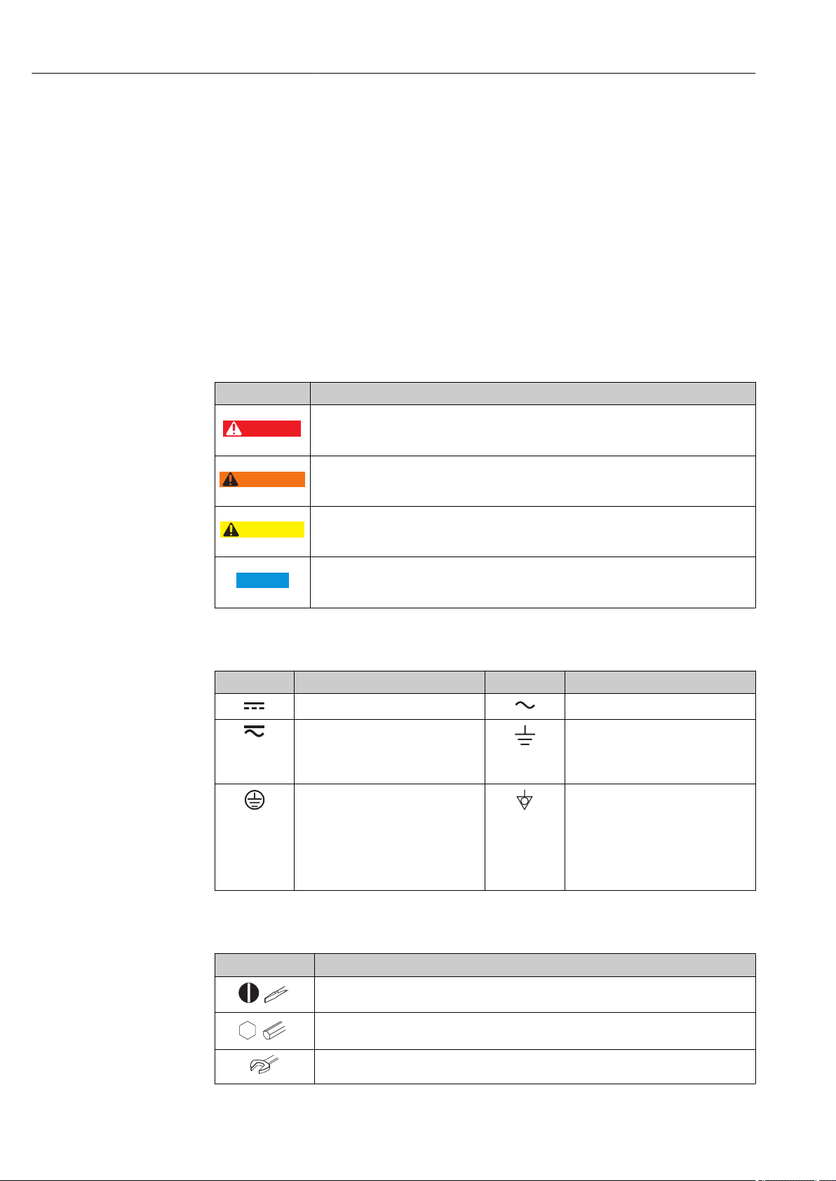
1.2.1 Safety symbols
Symbol Meaning
DANGER!
This symbol alerts you to a dangerous situation. Failure to avoid this situation will result in
serious or fatal injury.
WARNING!
This symbol alerts you to a dangerous situation. Failure to avoid this situation can result in
serious or fatal injury.
CAUTION!
This symbol alerts you to a dangerous situation. Failure to avoid this situation can result in
minor or medium injury.
NOTE!
This symbol contains information on procedures and other facts which do not result in
personal injury.
1.2.2 Electrical symbols
Symbol Meaning Symbol Meaning
Direct current Alternating current
Direct current and alternating current Ground connection
Protective ground connection
A terminal which must be connected
to ground prior to establishing any
other connections.
1.2.3 Tool symbols
Symbol Meaning
Flat blade screwdriver
Allen key
A grounded terminal which, as far as
the operator is concerned, is
grounded via a grounding system.
Equipotential connection
A connection that has to be connected
to the plant grounding system: This
may be a potential equalization line
or a star grounding system depending
on national or company codes of
practice.
Open-ended wrench
6 Endress+Hauser
Page 7
Proline Prosonic Flow B 200 HART Document information
,…,
,…,
-
.
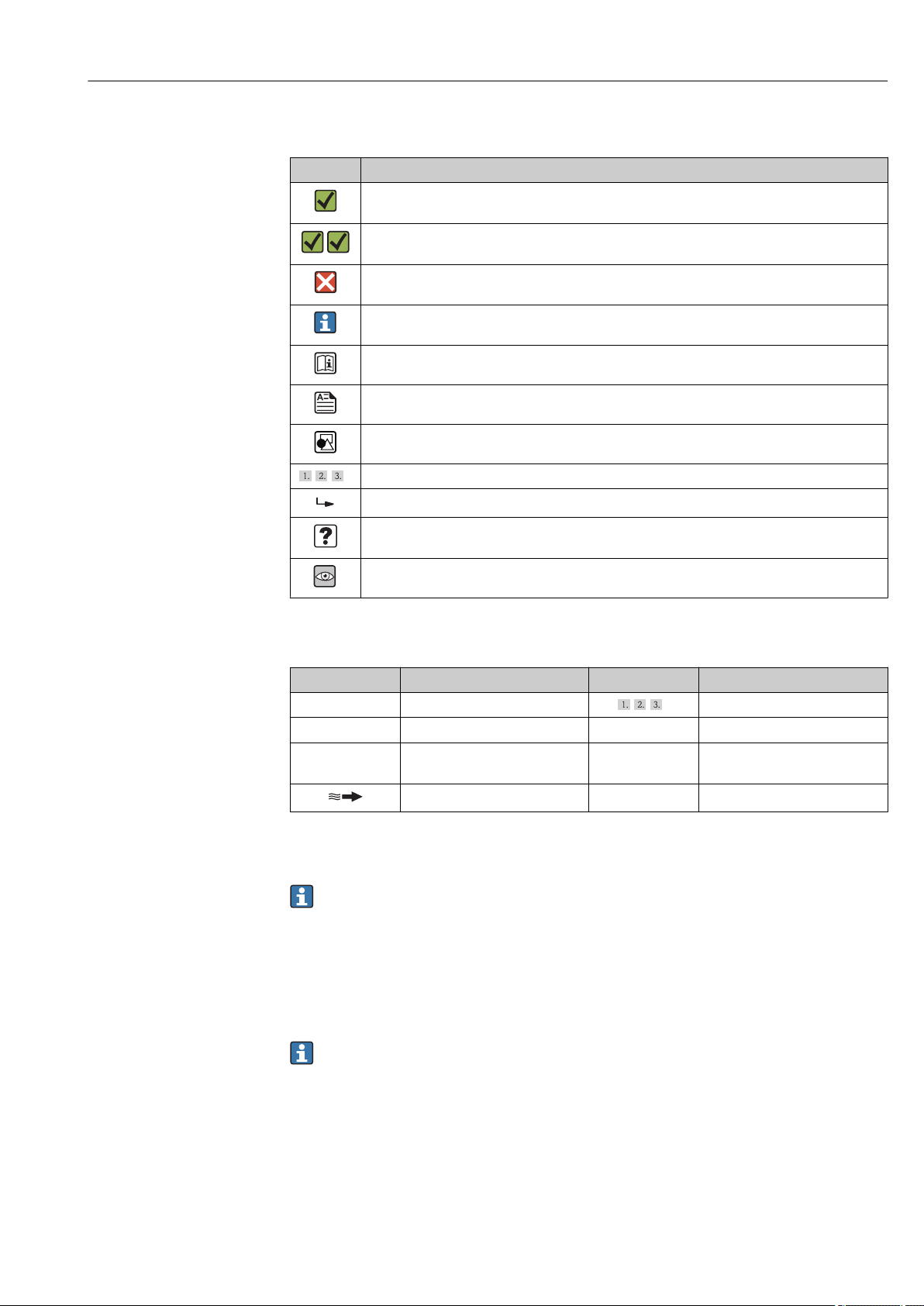
1.2.4 Symbols for certain types of information
Symbol Meaning
Permitted
Procedures, processes or actions that are permitted.
Preferred
Procedures, processes or actions that are preferred.
Forbidden
Procedures, processes or actions that are forbidden.
Tip
Indicates additional information.
Reference to documentation
Reference to page
Reference to graphic
Series of steps
Result of a sequence of actions
Help in the event of a problem
Visual inspection
1.2.5 Symbols in graphics
Symbol Meaning Symbol Meaning
1, 2, 3,... Item numbers
A, B, C, ... Views A-A, B-B, C-C, ... Sections
Hazardous area
Flow direction
Series of steps
Safe area (non-hazardous area)
1.3 Documentation
For an overview of the scope of the associated Technical Documentation, refer to the
following:
• The CD-ROM provided for the device (depending on the device version, the CD-ROM
might not be part of the delivery!)
• The W@M Device Viewer : Enter the serial number from the nameplate
(www.endress.com/deviceviewer)
• The Endress+Hauser Operations App: Enter the serial number from the nameplate
or scan the 2-D matrix code (QR code) on the nameplate.
For a detailed list of the individual documents along with the documentation code
→ 148
Endress+Hauser 7
Page 8

Document information Proline Prosonic Flow B 200 HART
1.3.1 Standard documentation
Document type Purpose and content of the document
Technical Information Planning aid for your device
The document contains all the technical data on the device and provides
an overview of the accessories and other products that can be ordered for
the device.
Brief Operating Instructions Guide that takes you quickly to the 1st measured value
The Brief Operating Instructions contain all the essential information
from incoming acceptance to initial commissioning.
Description of Device Parameters Reference for your parameters
The document provides a detailed explanation of each individual
parameter in the operating menu. The description is aimed at those who
work with the device over the entire life cycle and perform specific
configurations.
1.3.2 Supplementary device-dependent documentation
Additional documents are supplied depending on the device version ordered: Always
comply strictly with the instructions in the supplementary documentation. The
supplementary documentation is an integral part of the device documentation.
1.4 Registered trademarks
®
HART
Registered trademark of the HART Communication Foundation, Austin, USA
Applicator®, FieldCare®, Field XpertTM, HistoROM®, Heartbeat Technology
Registered or registration-pending trademarks of the Endress+Hauser Group
TM
8 Endress+Hauser
Page 9

Proline Prosonic Flow B 200 HART Basic safety instructions
2 Basic safety instructions
2.1 Requirements for the personnel
The personnel for installation, commissioning, diagnostics and maintenance must fulfill
the following requirements:
Trained, qualified specialists must have a relevant qualification for this specific function
‣
and task
Are authorized by the plant owner/operator
‣
Are familiar with federal/national regulations
‣
Before beginning work, the specialist staff must have read and understood the
‣
instructions in the Operating Instructions and supplementary documentation as well as
in the certificates (depending on the application)
Following instructions and basic conditions
‣
The operating personnel must fulfill the following requirements:
Being instructed and authorized according to the requirements of the task by the
‣
facility's owner-operator
Following the instructions in these Operating Instructions
‣
2.2 Designated use
Application and media
The measuring device described in these Instructions is intended only for flow
measurement of gases.
Depending on the version ordered, the measuring device can also measure potentially
explosive, flammable, poisonous and oxidizing media.
Measuring devices for use in hazardous areas, in hygienic applications or in applications
where there is an increased risk due to process pressure, are labeled accordingly on the
nameplate.
To ensure that the measuring device remains in proper condition for the operation time:
Only use the measuring device in full compliance with the data on the nameplate and
‣
the general conditions listed in the Operating Instructions and supplementary
documentation.
Check the nameplate to verify if the device ordered can be put to its intended use in the
‣
approval-related area (e.g. explosion protection, pressure vessel safety).
Use the measuring device only for media against which the process-wetted materials
‣
are adequately resistant.
If the measuring device is not operated at atmospheric temperature, compliance with
‣
the relevant basic conditions specified in the associated device documentation is
absolutely essential: "Documentation" section → 7.
Protect the measuring device permanently against corrosion from environmental
‣
influences.
Incorrect use
Non-designated use can compromise safety. The manufacturer is not liable for damage
caused by improper or non-designated use.
WARNING
L
Danger of breakage of the sensor due to corrosive or abrasive fluids or from
environmental conditions!
Verify the compatibility of the process fluid with the sensor material.
‣
Ensure the resistance of all fluid-wetted materials in the process.
‣
Keep within the specified pressure and temperature range.
‣
Endress+Hauser 9
Page 10

Basic safety instructions Proline Prosonic Flow B 200 HART
Verification for borderline cases:
For special fluids and fluids for cleaning, Endress+Hauser is glad to provide assistance
‣
in verifying the corrosion resistance of fluid-wetted materials, but does not accept any
warranty or liability as minute changes in the temperature, concentration or level of
contamination in the process can alter the corrosion resistance properties.
Residual risks
The external surface temperature of the housing can increase by max. 20 K due to the
power consumption of the electronic components. Hot process fluids passing through the
measuring device will further increase the surface temperature of the housing. The surface
of the sensor, in particular, can reach temperatures which are close to the fluid
temperature.
Possible burn hazard due to fluid temperatures!
For elevated fluid temperature, ensure protection against contact to prevent burns.
‣
2.3 Workplace safety
For work on and with the device:
Wear the required personal protective equipment according to federal/national
‣
regulations.
For welding work on the piping:
Do not ground the welding unit via the measuring device.
‣
If working on and with the device with wet hands:
It is recommended to wear gloves on account of the higher risk of electric shock.
‣
2.4 Operational safety
Risk of injury.
Operate the device in proper technical condition and fail-safe condition only.
‣
The operator is responsible for interference-free operation of the device.
‣
Conversions to the device
Unauthorized modifications to the device are not permitted and can lead to unforeseeable
dangers.
If, despite this, modifications are required, consult with Endress+Hauser.
‣
Repair
To ensure continued operational safety and reliability,
Carry out repairs on the device only if they are expressly permitted.
‣
Observe federal/national regulations pertaining to repair of an electrical device.
‣
Use original spare parts and accessories from Endress+Hauser only.
‣
2.5 Product safety
This measuring device is designed in accordance with good engineering practice to meet
state-of-the-art safety requirements, has been tested, and left the factory in a condition in
which it is safe to operate.
It meets general safety standards and legal requirements. It also complies with the EC
directives listed in the device-specific EC Declaration of Conformity. Endress+Hauser
confirms this by affixing the CE mark to the device.
10 Endress+Hauser
Page 11

Proline Prosonic Flow B 200 HART Basic safety instructions
2.6 IT security
We only provide a warranty if the device is installed and used as described in the
Operating Instructions. The device is equipped with security mechanisms to protect it
against any inadvertent changes to the device settings.
IT security measures in line with operators' security standards and designed to provide
additional protection for the device and device data transfer must be implemented by the
operators themselves.
Endress+Hauser 11
Page 12
Product description Proline Prosonic Flow B 200 HART
3 Product description
The device consists of a transmitter and a sensor.
The device is available as a compact version:
The transmitter and sensor form a mechanical unit.
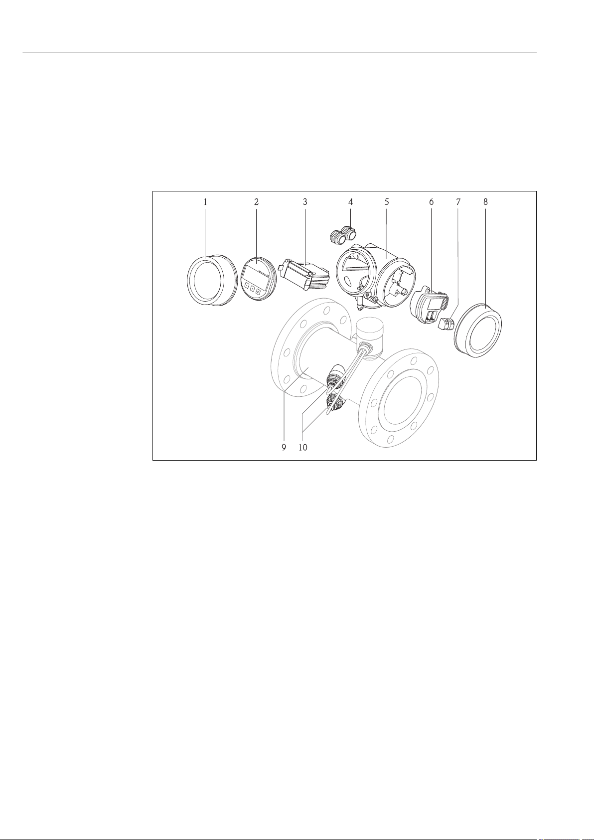
3.1 Product design
1 Important components of a measuring device
1 Electronics compartment cover
2 Display module
3 Main electronics module
4 Cable glands
5 Transmitter housing
6 I/O electronics module
7 Terminals (spring loaded terminals, pluggable)
8 Connection compartment cover
9 Sensor
10 Transducer
A0016199
12 Endress+Hauser
Page 13
Proline Prosonic Flow B 200 HART Incoming acceptance and product identification
1
+
2
1
+
2
4 Incoming acceptance and product
identification
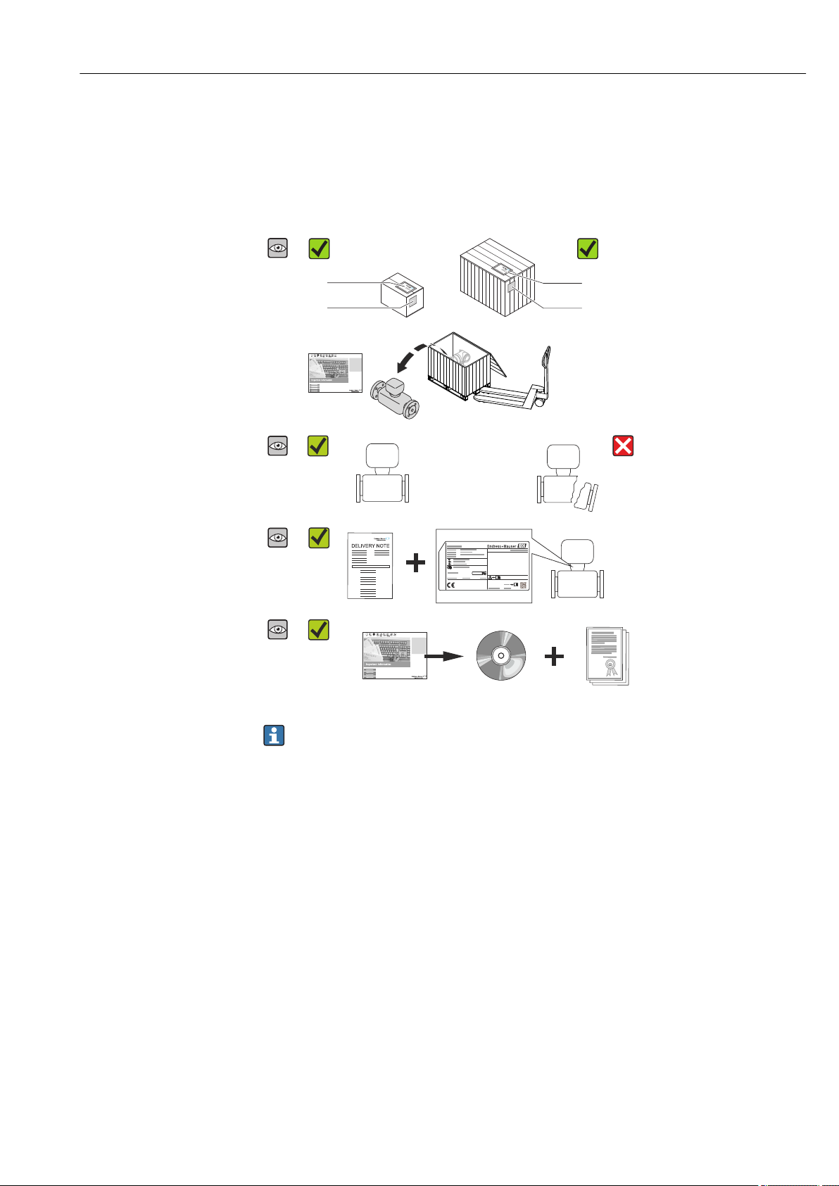
4.1 Incoming acceptance
Are the order codes on the
delivery note (1) and the
product sticker (2)
identical?
Are the goods undamaged?
Do the nameplate data
match the ordering
information on the delivery
note?
Is the CD-ROM with the
Technical Documentation
(depends on device
version) and documents
present?
• If one of the conditions is not satisfied, contact your Endress+Hauser Sales Center.
• Depending on the device version, the CD-ROM might not be part of the delivery!
The Technical Documentation is available via the Internet or via the Endress+Hauser
Operations App, see the "Product identification" section → 14.
4.2 Product identification
The following options are available for identification of the measuring device:
• Nameplate specifications
• Order code with breakdown of the device features on the delivery note
• Enter serial numbers from nameplates in W@M Device Viewer
(www.endress.com/deviceviewer): All information about the measuring device is
displayed.
• Enter the serial number from the nameplates into the Endress+Hauser Operations App
or scan the 2-D matrix code (QR code) on the nameplate with the Endress+Hauser
Operations App: all the information for the measuring device is displayed.
Endress+Hauser 13
Page 14
Incoming acceptance and product identification Proline Prosonic Flow B 200 HART
Ordercode:
Ext.ord.cd.:
Ser.no.:
Date:
i
i
Patents
322540-0001
1
2
3 4 5
6
7
8
9
10 11
12
14
15
16
17
13
For an overview of the scope of the associated Technical Documentation, refer to the
following:
• The chapters "Additional standard documentation on the device" → 8 and
"Supplementary device-dependent documentation" → 8
• The W@M Device Viewer: Enter the serial number from the nameplate
(www.endress.com/deviceviewer)
• The Endress+Hauser Operations App: Enter the serial number from the nameplate or
scan the 2-D matrix code (QR code) on the nameplate.
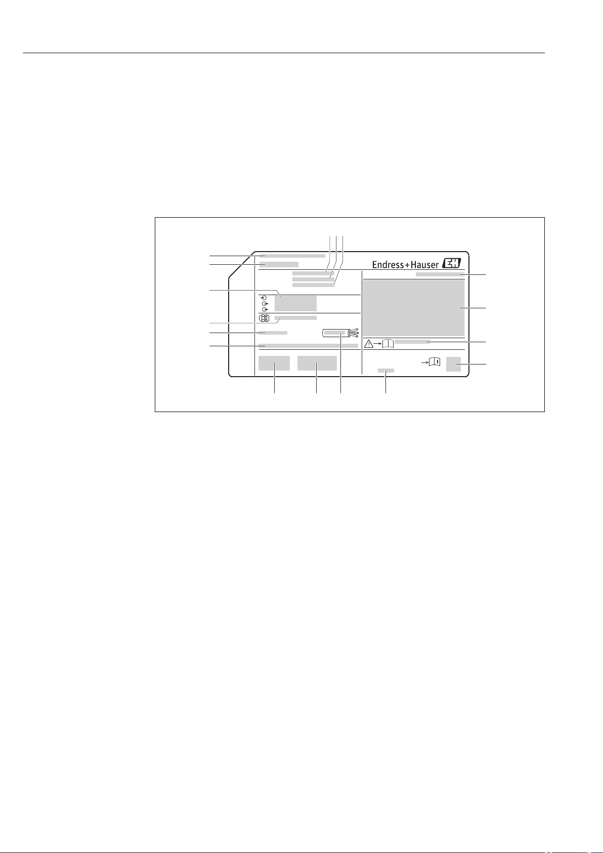
4.2.1 Transmitter nameplate
A0013906
2 Example of a transmitter nameplate
1 Manufacturing location
2 Name of the transmitter
3 Order code
4 Serial number (Ser. no.)
5 Extended order code (Ext. ord. cd.)
6 Electrical connection data, e.g. available inputs and outputs, supply voltage
7 Type of cable glands
8 Permitted ambient temperature (Ta)
9 Firmware version (FW) and device revision (Dev.Rev.) from the factory
10 CE mark, C-Tick
11 Additional information on version: certificates, approvals
12 Permitted temperature range for cable
13 Manufacturing date: year-month
14 Degree of protection
15 Approval information for explosion protection
16 Document number of safety-related supplementary documentation
17 2-D matrix code
14 Endress+Hauser
Page 15

Proline Prosonic Flow B 200 HART Incoming acceptance and product identification
6
Date:
Order code:
Ser.No.:
Ext. ord. cd.:
Tm:
Materials:
i
1
2
3 4 5
13
9
10
11
147
15
17
16
pnom = PS =
ptest=
8
Ta:
12
4.2.2 Sensor nameplate
A0016420
3 Example of 1st sensor nameplate
1 Manufacturing location
2 Name of the sensor
3 Order code
4 Serial number
5 Extended order code
6 Nominal diameter of the sensor
7 Flange type
8 Test pressure of the sensor
9 Nominal pressure of the sensor (max. permitted pressure)
10 Material of measuring tube and seal
11 Medium temperature range
12 Ambient temperature range
13 Manufacturing date: year-month
14 2-D matrix code
15 Degree of protection, approval information for explosion protection and Pressure Equipment Directive
16 CE mark, C-Tick
17 Document number of safety-related supplementary documentation
Order code
The measuring device is reordered using the order code.
Extended order code
• The device type (product root) and basic specifications (mandatory features) are
always listed.
• Of the optional specifications (optional features), only the safety and approvalrelated specifications are listed (e.g. LA). If other optional specifications are also
ordered, these are indicated collectively using the # placeholder symbol (e.g. #LA#).
• If the ordered optional specifications do not include any safety and approval-related
specifications, they are indicated by the + placeholder symbol (e.g. XXXXXX-ABCDE
+).
Endress+Hauser 15
Page 16
Storage and transport Proline Prosonic Flow B 200 HART
5 Storage and transport
5.1 Storage conditions
Observe the following notes for storage:
• Store in the original packaging to ensure protection from shock.
• Do not remove protective covers or protective caps installed on process connections.
They prevent mechanical damage to the sealing surfaces and contamination in the
measuring tube.
• Protect from direct sunlight to avoid unacceptably high surface temperatures.
• Store in a dry and dust-free place.
• Do not store outdoors.
Storage temperature: –40 to +80 °C (–40 to +176 °F),
preferably at +20 °C (+68 °F)
5.2 Transporting the product
Transport the measuring device to the measuring point in the original packaging.
A0015604
Do not remove protective covers or caps installed on process connections. They
prevent mechanical damage to the sealing surfaces and contamination in the
measuring tube.
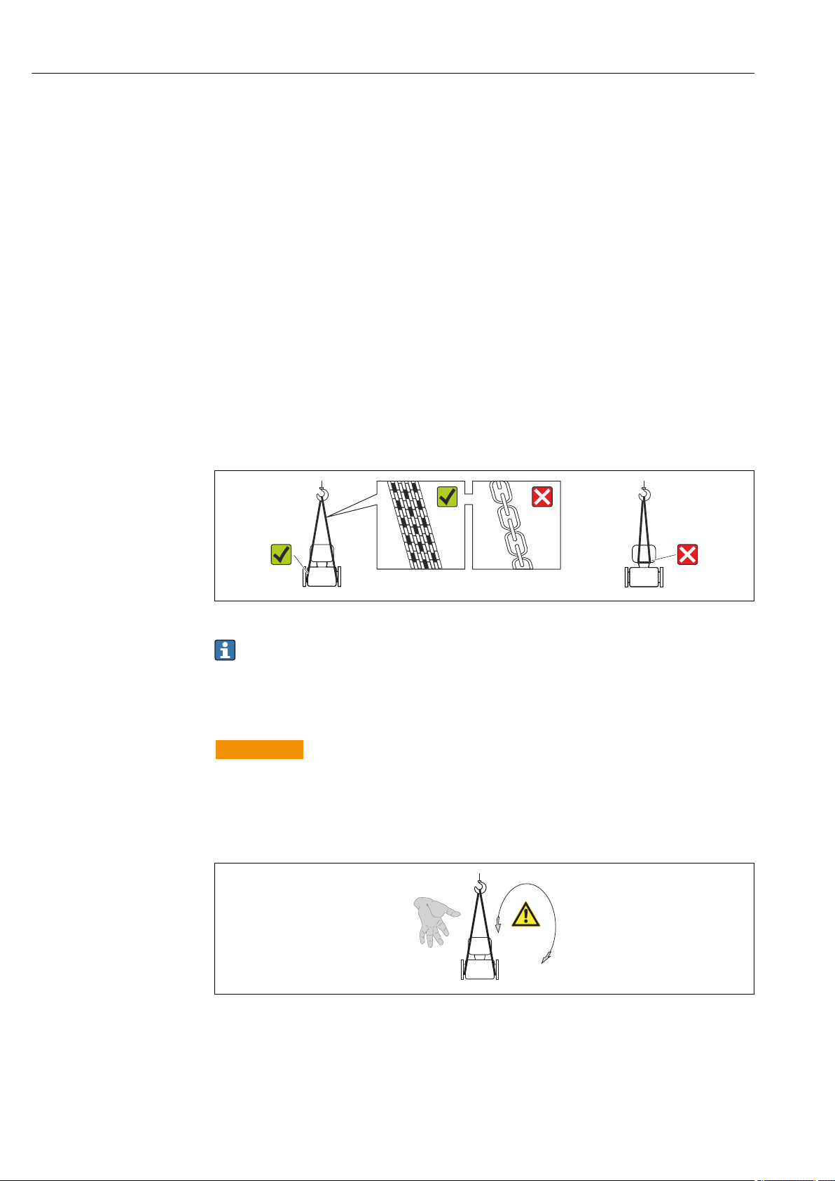
5.2.1 Measuring devices without lifting lugs
WARNING
L
Center of gravity of the measuring device is higher than the suspension points of the
webbing slings.
Risk of injury if the measuring device slips.
Secure the measuring device against slipping or turning.
‣
Observe the weight specified on the packaging (stick-on label).
‣
A0015606
16 Endress+Hauser
Page 17

Proline Prosonic Flow B 200 HART Storage and transport
5.2.2 Measuring devices with lifting lugs
CAUTION
L
Special transportation instructions for devices with lifting lugs
Only use the lifting lugs fitted on the device or flanges to transport the device.
‣
The device must always be secured at two lifting lugs at least.
‣
5.2.3 Transporting with a fork lift
If transporting in wood crates, the floor structure enables the crates to be lifted lengthwise
or at both sides using a forklift.
5.3 Packaging disposal
All packaging materials are environmentally friendly and 100% recyclable:
• Measuring device secondary packaging: polymer stretch film that conforms to EC
Directive 2002/95/EC (RoHS).
• Packaging:
– Wood crate, treated in accordance with ISPM 15 standard, which is confirmed by the
affixed IPPC logo.
or
– Carton in accordance with European Packaging Directive 94/62EC; recyclability is
confirmed by the affixed RESY symbol.
• Seaworthy packaging (optional): Wood crate, treated in accordance with ISPM 15
standard, which is confirmed by the affixed IPPC logo.
• Carrying and mounting hardware:
– Disposable plastic pallet
– Plastic straps
– Plastic adhesive strips
• Dunnage: Paper cushion
Endress+Hauser 17
Page 18
Installation Proline Prosonic Flow B 200 HART
6 Installation
6.1 Installation conditions
No special measures such as supports are necessary. External forces are absorbed by the
construction of the device.
6.1.1 Mounting position
Mounting location
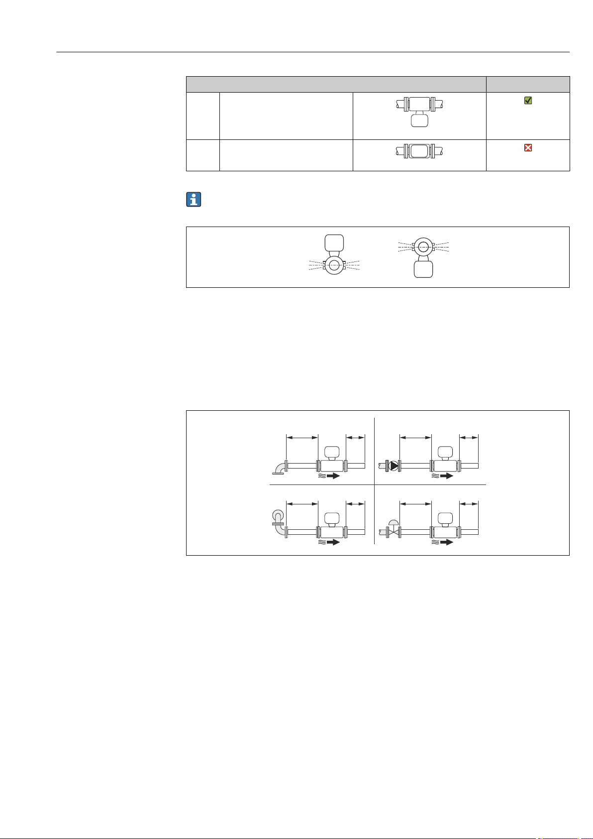
Orientation
The direction of the arrow on the sensor helps you to install the sensor according to the
flow direction (direction of medium flow through the piping).
• Install the measuring device in a parallel plane free of external mechanical stress.
• The internal diameter of the pipe must match the internal diameter of the sensor:
see the "Technical Information" device document, "Design and dimensions" section.
Orientation Compact version
A Vertical orientation
A0015545
B Horizontal orientation, transmitter
head up *
A0015543
A0015895
A0015589
18 Endress+Hauser
Page 19
Proline Prosonic Flow B 200 HART Installation
0°
+3°
–3°
0°
+3°
–3°
20 × DN 3 × DN
1
3
2
4
20 × DN 3 × DN
20 × DN 3 × DN20 × DN 3 × DN
Orientation Compact version
C Horizontal orientation, transmitter
head down *
A0015590
D Horizontal orientation, transmitter
head at side
A0015592
* A maximum deviation of only ±3° is permitted for the horizontal alignment of the
converters.
A0016534
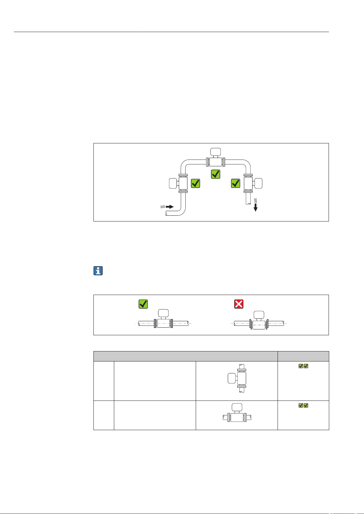
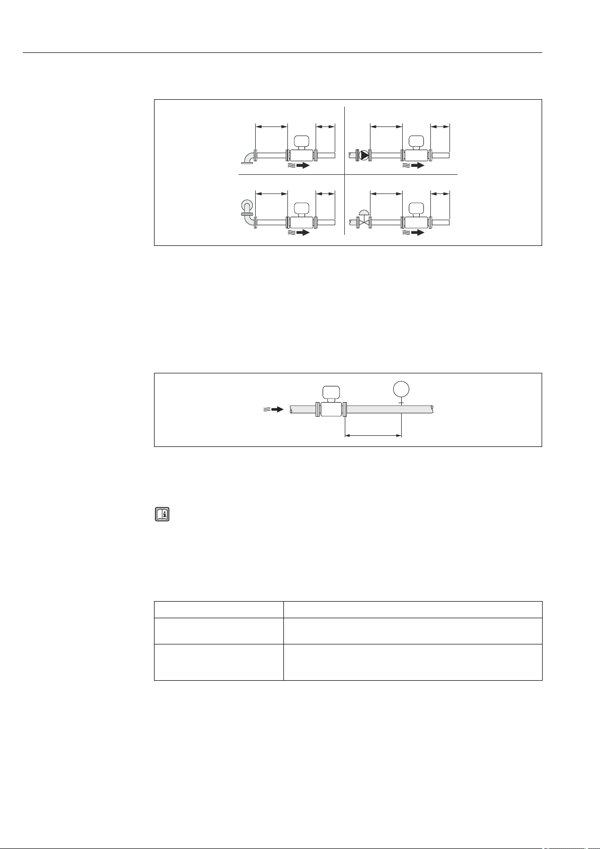
Inlet and outlet runs
If possible, the sensor should be installed upstream from valves, T-pieces, elbows etc. To
attain the specified level of accuracy of the measuring device, the below mentioned inlet
and outlet runs must be maintained at minimum. If there are several flow disturbances
present, the longest specified inlet run must be maintained.
Single-path version: DN 50 (2"), DN 80 (3")
4 Single-path version: minimum inlet and outlet runs with various flow obstructions
1 90 ° elbow or T-section
2 Pump
3 2 × 90 ° elbow, 3-dimensional
4 Control valve
A0015453
Endress+Hauser 19
Page 20
Installation Proline Prosonic Flow B 200 HART
10 × DN 3 × DN
1
3
2
4
10 × DN 3 × DN
10 × DN 3 × DN10 × DN 3 × DN
3 × DN
PT
Two-path version: DN 100 to 200 (4 to 8")
A0015553
5 Two-path version: minimum inlet and outlet runs with various flow obstructions
1 90 ° elbow or T-section
2 Pump
3 2 × 90 ° elbow, 3-dimensional
4 Control valve
Outlet runs when installing external devices
If installing an external device, observe the specified distance.
PT Pressure transmitter
Installation dimensions
For the dimensions and installation lengths of the device, see the "Technical
Information" document, "Mechanical construction" section
6.1.2 Requirements from environment and process
Ambient temperature range
Transmitter –40 to +60 °C (–40 to +140 °F)
Local display –20 to +60 °C (–4 to +140 °F), the readability of the display may be
impaired at temperatures outside the temperature range.
Sensor • Flange material carbon steel: –10 to +60 °C (+14 to +140 °F)
• Flange material stainless steel: –40 to +60 °C (–40 to +140 °F)
• Version without flange: –40 to +60 °C (–40 to +140 °F)
A0015901
If operating outdoors:
‣
Avoid direct sunlight, particularly in warm climatic regions.
System pressure
Sensor
Max. 10 bar (145 psi)
20 Endress+Hauser
Page 21

Proline Prosonic Flow B 200 HART Installation
Thermal insulation
For optimum temperature and methane fraction measurement (order characteristic for
"Sensor version", option 2 "Volume flow + Biogas analysis"), make sure that heat is neither
lost nor applied to the sensor. Thermal insulation can ensure that such heat transfer does
not take place.
Thermal insulation is particularly recommended in situations where there is a large
difference between the process temperature and the ambient temperature. This can result
in heat convection errors during temperature measurement. A further factor which can
lead to measurement errors due to heat convection is a low flow velocity.
6.2 Mounting the measuring device
6.2.1 Required tools
For transmitter
• For turning the transmitter housing: Open-ended wrench8 mm
• For opening the securing clamps: Allen key3 mm
For sensor
For flanges and other process connections: Corresponding mounting tools
6.2.2 Preparing the measuring device
1. Remove all remaining transport packaging.
2. Remove any protective covers or protective caps present from the sensor.
3. Remove stick-on label on the electronics compartment cover.
6.2.3 Mounting the measuring device
WARNING
L
Danger due to improper process sealing!
Ensure that the inside diameters of the gaskets are greater than or equal to that of the
‣
process connections and piping.
Ensure that the gaskets are clean and undamaged.
‣
Install the gaskets correctly.
‣
1. Ensure that the direction of the arrow on the sensor matches the flow direction of
the medium.
2. Install the measuring device or turn the transmitter housing so that the cable entries
do not point upwards.
A0013964
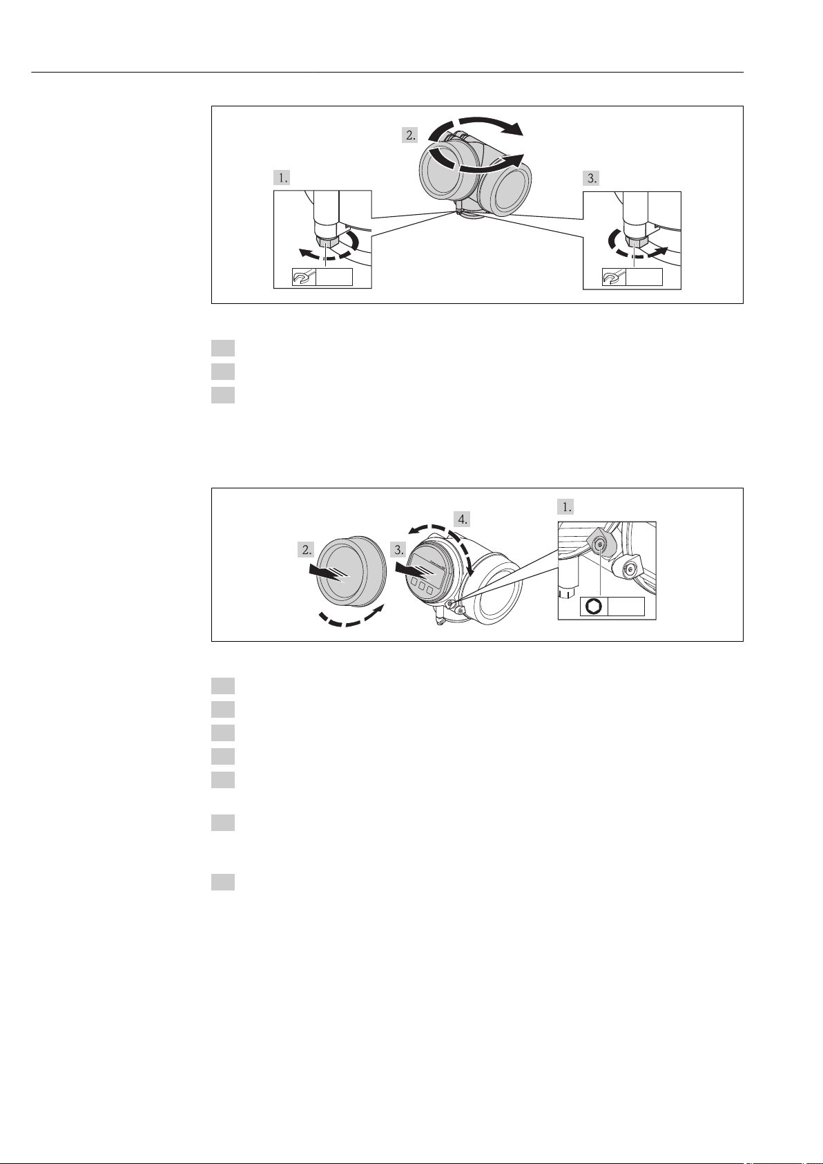
6.2.4 Turning the transmitter housing
To provide easier access to the connection compartment or display module, the transmitter
housing can be turned.
Endress+Hauser 21
Page 22
Installation Proline Prosonic Flow B 200 HART
max.350°
8mm
8mm
+
E
–
1
3mm
A0013713
1. Release the fixing screw.
2. Turn the housing to the desired position.
3. Firmly tighten the securing screw.
6.2.5 Turning the display module
The display module can be turned to optimize display readability and operability.
1. Loosen the securing clamp of the electronics compartment cover using an Allen key.
2. Unscrew cover of the electronics compartment from the transmitter housing.
3. Optional: pull out the display module with a gentle rotational movement.
4. Rotate the display module into the desired position: Max. 8 × 45° in each direction.
5. Without display module pulled out:
Allow display module to engage at desired position.
6. With display module pulled out:
Feed the cable into the gap between the housing and main electronics module and
plug the display module into the electronics compartment until it engages.
7. Reverse the removal procedure to reassemble the transmitter.
A0013905
22 Endress+Hauser
Page 23

Proline Prosonic Flow B 200 HART Installation
6.3 Post-mounting check
Is the device undamaged (visual inspection)?
Does the measuring device conform to the measuring point specifications?
For example:
• Process temperature → 139
• Process pressure (refer to the section on "Pressure-temperature ratings" in the "Technical
Information" document)
• Ambient temperature range → 20
• Measuring range → 130
Has the correct orientation for the sensor been selected → 18?
• According to sensor type
• According to medium temperature
• According to medium properties (outgassing, with entrained solids)
Does the arrow on the sensor match the direction of flow of the medium through the piping
→ 18?
Are the measuring point identification and labeling correct (visual inspection)?
Is the device adequately protected from precipitation and direct sunlight?
Are the securing screw and securing clamp tightened securely?
Endress+Hauser 23
Page 24

Electrical connection Proline Prosonic Flow B 200 HART
7 Electrical connection
The measuring device does not have an internal circuit breaker. For this reason,
assign the measuring device a switch or power-circuit breaker so that the power
supply line can be easily disconnected from the mains.
7.1 Connection conditions
7.1.1 Required tools
• For cable entries: Use corresponding tools
• For securing clamp: Allen key 3 mm
• Wire stripper
• When using stranded cables: crimping tool for ferrule
• For removing cables from terminal: flat blade screwdriver ≤3 mm (0.12 in)
7.1.2 Connecting cable requirements
The connecting cables provided by the customer must fulfill the following requirements.
Electrical safety
In accordance with applicable federal/national regulations.
Permitted temperature range
• –40 °C (–40 °F) to +80 °C (+176 °F)
• Minimum requirement: cable temperature range ≥ ambient temperature +20 K
Signal cable
Current output
• For 4-20 mA: standard installation cable is sufficient.
• For 4-20 mA HART: Shielded cable recommended. Observe grounding concept of the
plant.
Pulse/frequency/switch output
Standard installation cable is sufficient.
Current input
Standard installation cable is sufficient.
Cable diameter
• Cable glands supplied:
M20 × 1.5 with cable 6 to 12 mm (0.24 to 0.47 in)
• Plug-in spring terminals for device version without integrated overvoltage protection:
wire cross-sections 0.5 to 2.5 mm2 (20 to 14 AWG)
• Screw terminals for device version with integrated overvoltage protection: wire crosssections 0.2 to 2.5 mm2 (24 to 14 AWG)
24 Endress+Hauser
Page 25
Proline Prosonic Flow B 200 HART Electrical connection
–
4
+
1
–
2
+
3
1
2
4
–
6
+
5
3
+
1
–
2
–
4
+
3
–
6
+
5
3
1
2
4
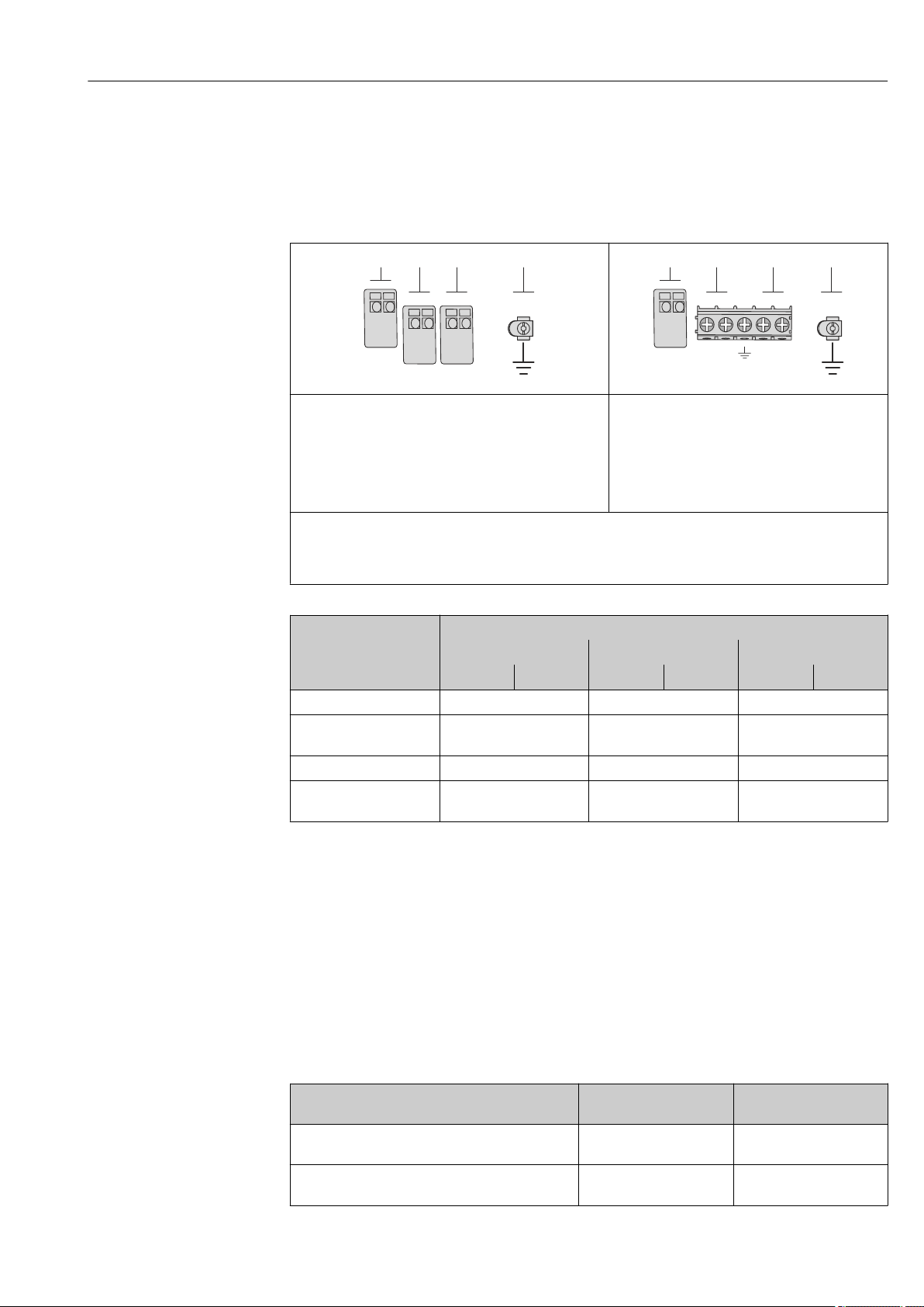
7.1.3 Terminal assignment
Transmitter
4-20 mA HART connection version with additional inputs and outputs
A0020738
Maximum number of terminals
Terminals 1 to 6:
Without integrated overvoltage protection
1
Output 1 (passive): supply voltage and signal transmission
2
Output 2 (passive): supply voltage and signal transmission
3
Input (passive): supply voltage and signal transmission
4
Ground terminal for cable shield
Order code for "Output" Terminal numbers
Output 1 Output 2 Input
1 (+) 2 (-) 3 (+) 4 (-) 5 (+) 6 (-)
Option A 4-20 mA HART (passive) - -
Option B
Option C
Option D
1)
1)
1) 2)
4-20 mA HART (passive)
4-20 mA HART (passive) 4-20 mA analog (passive) -
4-20 mA HART (passive)
Maximum number of terminals for order code for
"Accessory mounted", option NA "Overvoltage
protection"
• Terminals 1 to 4:
With integrated overvoltage protection
• Terminals 5 to 6:
Without integrated overvoltage protection
Pulse/frequency/switch
output (passive)
Pulse/frequency/switch
output (passive)
A0020739
-
4-20 mA current input
(passive)
1) Output 1 must always be used; output 2 is optional.
2) The integrated overvoltage protection is not used with option D: Terminals 5 and 6 (current input) are not
protected against overvoltage.
7.1.4 Requirements for the supply unit
Supply voltage
Transmitter
An external power supply is required for each output.
The following supply voltage values apply for the outputs available:
Order code for "Output"
Option A
Endress+Hauser 25
Option B : 4-20 mA HART, pulse/frequency/switch
output
1) 2)
: 4-20 mA HART • For 4 mA: ≥ DC 16 V
Minimum
terminal voltage
• For 20 mA: ≥ DC 12 V
• For 4 mA: ≥ DC 16 V
• For 20 mA: ≥ DC 12 V
Maximum
terminal voltage
DC 35 V
DC 35 V
Page 26
Electrical connection Proline Prosonic Flow B 200 HART
0
100
200
300
400
500
14
16 18 20
22 24
26 28 30 32
U [V]
s
R [ ]bW
600
220
16.8 23
34 36
1.1 1.21
35
Order code for "Output"
Option C : 4-20 mA HART + 4-20 mA analog • For 4 mA: ≥ DC 16 V
Option D: 4-20 mA HART, pulse/frequency/switch
output, 4-20 mA current input
1) External supply voltage of the power supply unit with load.
2) For device versions with SD03 local display: The terminal voltage must be increased by DC 2 V if
backlighting is used.
3) Voltage drop 2.2 to 3 V for 3.59 to 22 mA
3)
Minimum
terminal voltage
• For 20 mA: ≥ DC 12 V
≥ DC 12 V
Maximum
terminal voltage
DC 30 V
DC 35 V
Load
Load for current output: 0 to 500 Ω, depending on the external supply voltage of the power
supply unit
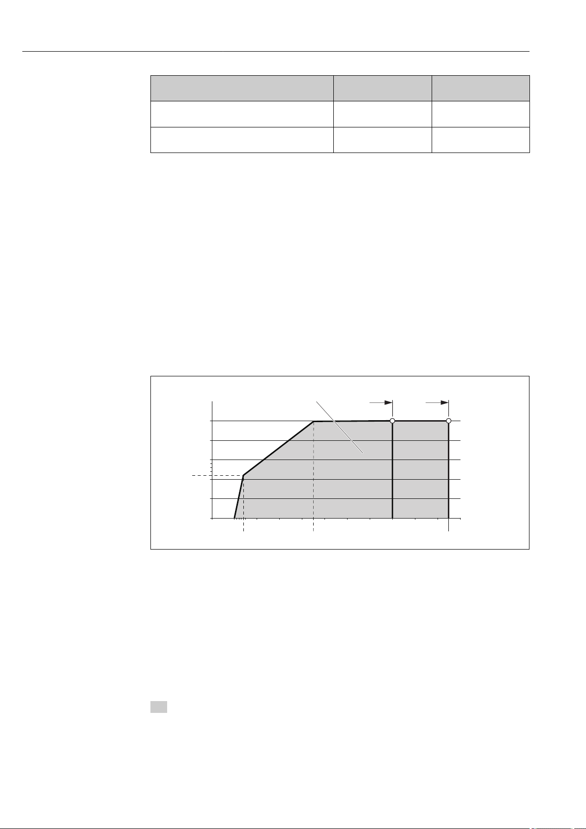
Calculation of the maximum load
Depending on the supply voltage of the power supply unit (US), the maximum load (RB)
including line resistance must be observed to ensure adequate terminal voltage at the
device. In doing so, observe the minimum terminal voltage
• For US = 16.0 to 16.8 V: RB ≤ (US - 16.0 V): 0.0036 A
• For US = 16.8 to 23.0 V: RB ≤ (US - 12.0 V): 0.022 A
• For US = 23.0 to 30.0 V: RB ≤ 500 Ω
1 Operating range
1.1 For order code for "Output", option A "4-20 mA HART"/option B "4-20 mA HART, pulse/frequency/switch
output" with Ex i and option C "4-20 mA HART + 4-20 mA analog"
1.2 For order code for "Output", option A "4-20 mA HART"/option B "4-20 mA HART, pulse/frequency/switch
output" with non-Ex and Ex d
Sample calculation
Supply voltage of the power supply unit: US = 17.5 V
Maximum load: RB ≤ (17.5 V - 12.0 V): 0.022 A = 250 Ω
7.1.5 Preparing the measuring device
1. Remove dummy plug if present.
26 Endress+Hauser
A0018972
Page 27
Proline Prosonic Flow B 200 HART Electrical connection
10(0.4)
mm(in)
20 mm3mm
2. NOTICE
Insufficient sealing of the housing!
Operational reliability of the measuring device could be compromised.
Use suitable cable glands corresponding to the degree of protection.
‣
If measuring device is delivered without cable glands:
Provide suitable cable gland for corresponding connecting cable .
3. If measuring device is delivered with cable glands:
Observe cable specification .
7.2 Connecting the measuring device
NOTICE
Limitation of electrical safety due to incorrect connection!
Have electrical connection work carried out by correspondingly trained specialists only.
‣
Observe applicable federal/national installation codes and regulations.
‣
Comply with local workplace safety regulations.
‣
For use in potentially explosive atmospheres, observe the information in the device-
‣
specific Ex documentation.
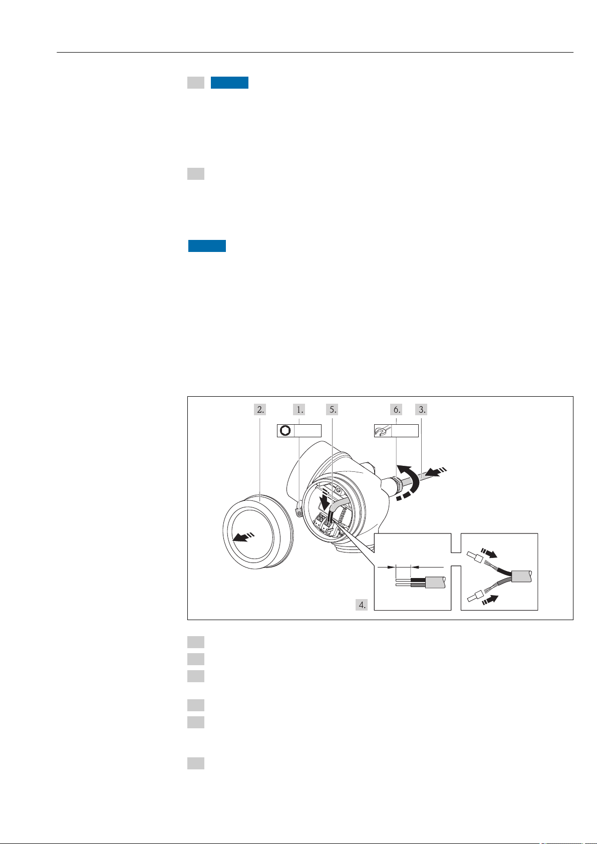
7.2.1 Connecting the transmitter
Connection via terminals
A0013836
1. Loosen the securing clamp of the connection compartment cover.
2. Unscrew the connection compartment cover.
3. Push the cable through the cable entry . To ensure tight sealing, do not remove the
sealing ring from the cable entry.
4. Strip the cable and cable ends. In the case of stranded cables, also fit ferrules.
5. Connect the cable in accordance with the terminal assignment . For HART
communication: when connecting the cable shielding to the ground terminal, observe
the grounding concept of the facility.
6. Firmly tighten the cable glands.
Endress+Hauser 27
Page 28
Electrical connection Proline Prosonic Flow B 200 HART
mm (in)
213 4
3 (0.12)
7.
WARNING
L
Housing degree of protection may be voided due to insufficient sealing of the
housing.
Screw in the screw without using any lubricant. The threads on the cover are
‣
coated with a dry lubricant.
Reverse the removal procedure to reassemble the transmitter.
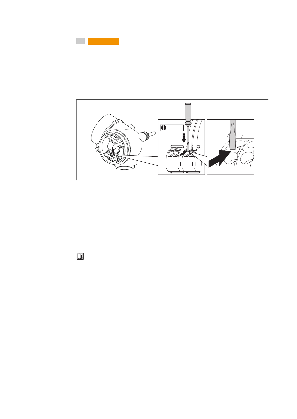
Removing a cable
A0013835
To remove a cable from the terminal, use a flat-blade screwdriver to push the slot
‣
between the two terminal holes while simultaneously pulling the cable end out of the
terminal.
7.2.2 Ensuring potential equalization
Requirements
No special measures for potential equalization are required.
For devices intended for use in hazardous locations, please observe the guidelines in
the Ex documentation (XA).
28 Endress+Hauser
Page 29
Proline Prosonic Flow B 200 HART Electrical connection
2
3
4...20 mA
41
+
-
5
+
-
2
4...20 mA
3
1
+
-
4
+
–
+
-
7.3 Special connection instructions
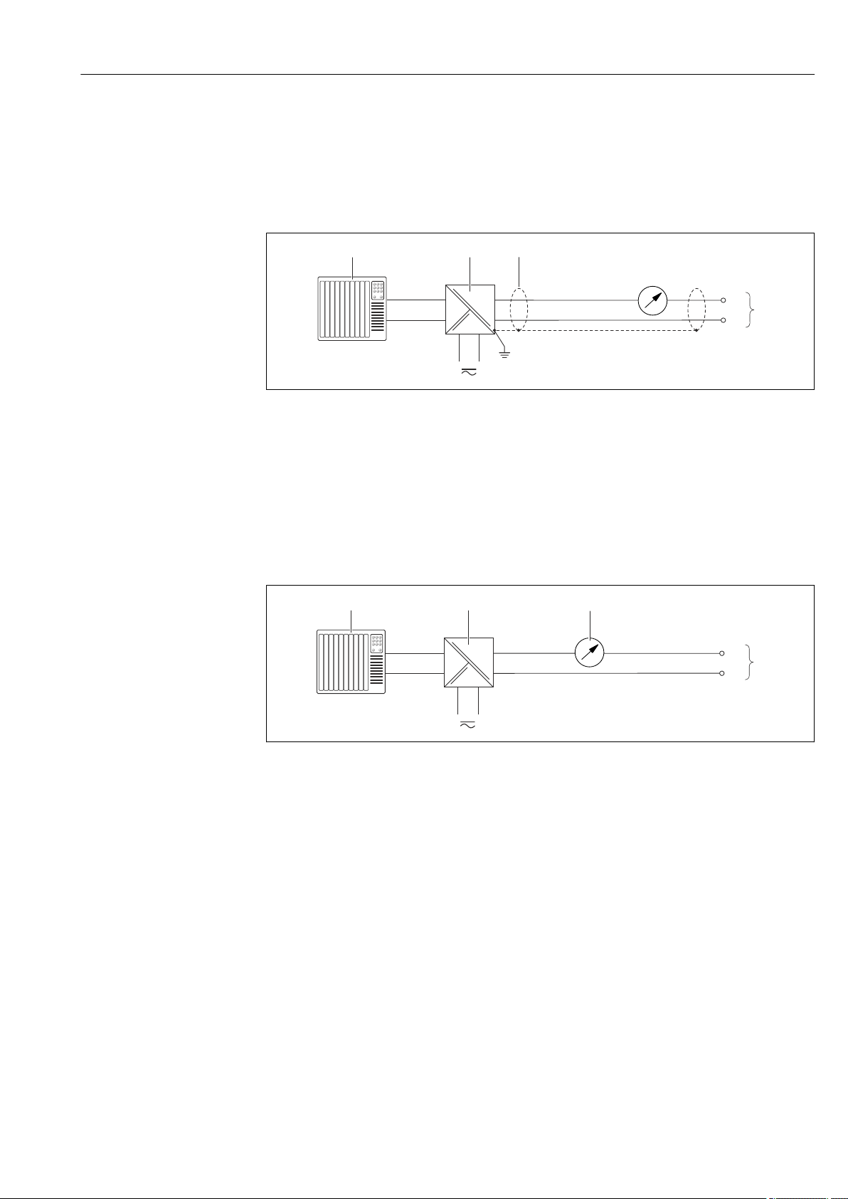
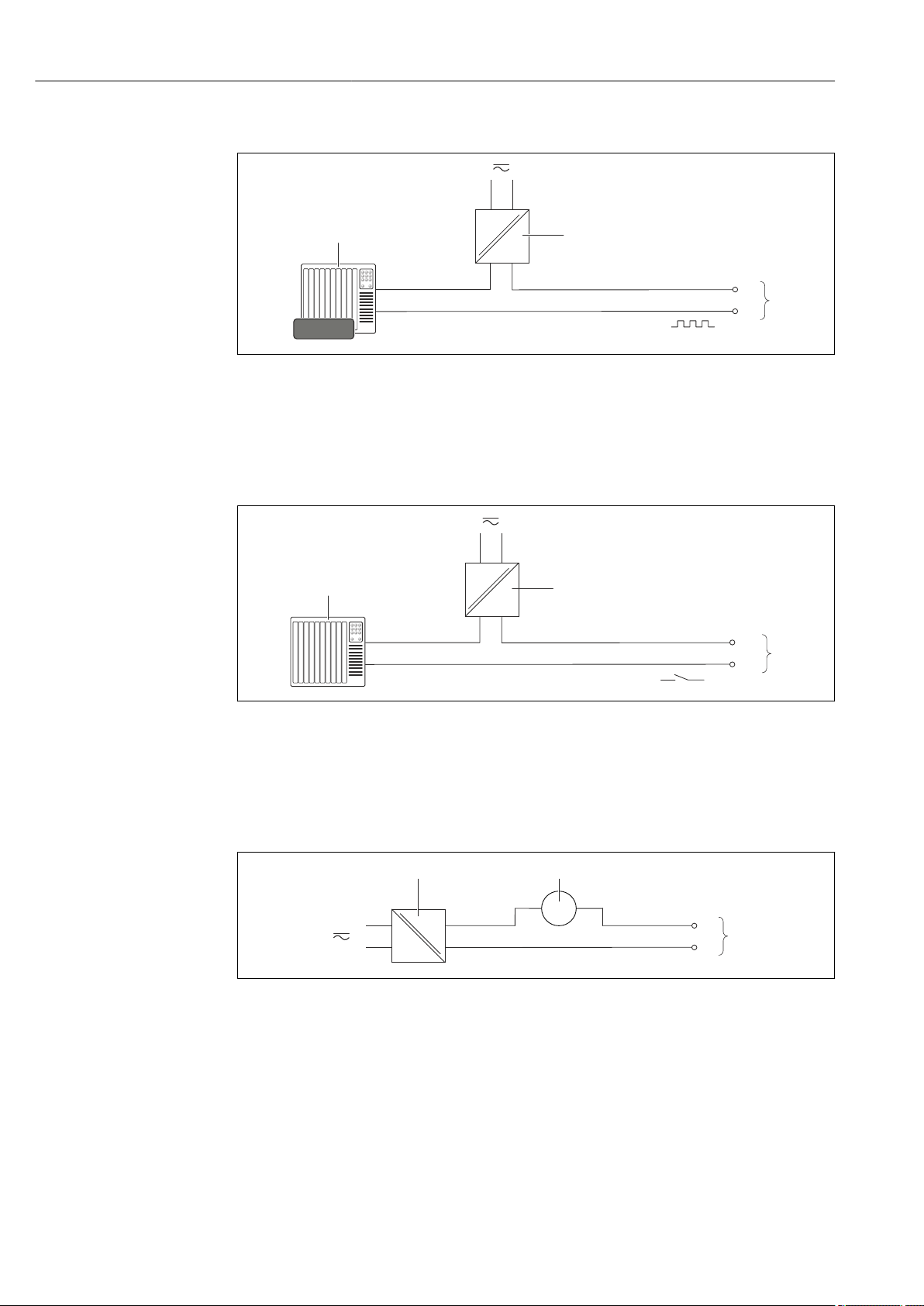
7.3.1 Connection examples
Current output 4-20 mA HART
A0015511
6 Connection example for 4-20 mA HART current output (passive)
1 Automation system with current input (e.g. PLC)
2 Active barrier for power supply with integrated resistor for HART communication (≥ 250 Ω)(e.g. RN221N)
Connection for HART operating devices → 145
Observe the maximum load → 26
3 Cable shield, observe cable specifications
4 Analog display unit: observe maximum load → 26
5 Transmitter
Current output 4-20 mA
7 Connection example for 4-20 mA current output (passive)
1 Automation system with current input (e.g. PLC)
2 Active barrier for power supply (e.g. RN221N)
3 Analog display unit: observe maximum load → 26
4 Transmitter
A0015512
Endress+Hauser 29
Page 30
Electrical connection Proline Prosonic Flow B 200 HART
1
+
_
12345
2
+
–
+
–
3
1
+
_
+
_
2
+
_
3
1
+
-
3
+
-
2
Pulse/frequency output
A0016801
8 Connection example for pulse/frequency output (passive)
1 Automation system with pulse/frequency input (e.g. PLC)
2 Power supply
3 Transmitter: observe input values
Switch output
9 Connection example for switch output (passive)
1 Automation system with switch input (e.g. PLC)
2 Power supply
3 Transmitter: observe input values
Current input
10 Connection example for 4-20 mA current input
1 Power supply
2 External measuring device (for capturing the pressure)
3 Transmitter: observe input values → 131
A0016802
A0020741
30 Endress+Hauser
Page 31

Proline Prosonic Flow B 200 HART Electrical connection
3
4...20 mA
5
1
+
-
3
6
+
–
+
+
–
+
–
+
–
+
–
–
2
4
4
7
+
-
HART input
A0016029
11 Connection example for HART input with a common negative
1 Automation system with HART output (e.g. PLC)
2 Resistor for HART communication (≥ 250 Ω): observe maximum load → 26
3 Active barrier for power supply (e.g. RN221N)
4 Cable shield, observe cable specifications
5 Analog display unit: observe maximum load → 26
6 Pressure transmitter (e.g. Cerabar M, Cerabar S): see requirements
7 Transmitter
7.4 Ensuring the degree of protection
The measuring device fulfills all the requirements for the IP66/67 degree of protection,
Type 4X enclosure.
To guarantee IP66/67 degree of protection, Type 4X enclosure, carry out the following
steps after the electrical connection:
1. Check that the housing seals are clean and fitted correctly. Dry, clean or replace the
seals if necessary.
2. Tighten all housing screws and screw covers.
3. Firmly tighten the cable glands.
4. To ensure that moisture does not enter the cable entry, route the cable so that it
loops down before the cable entry ("water trap").
5. Insert dummy plugs into unused cable entries.
A0013960
Endress+Hauser 31
Page 32

Electrical connection Proline Prosonic Flow B 200 HART
7.5 Post-connection check
Are cables or the device undamaged (visual inspection)?
Do the cables comply with the requirements ?
Do the cables have adequate strain relief?
Are all the cable glands installed, firmly tightened and leak-tight? Cable run with "water trap"
→ 31 ?
Depending on the device version: are all the device plugs firmly tightened ?
Does the supply voltage match the specifications on the transmitter nameplate ?
Is the terminal assignment correct ?
If supply voltage is present, do values appear on the display module?
Are all housing covers installed and firmly tightened?
Is the securing clamp tightened correctly?
32 Endress+Hauser
Page 33

Proline Prosonic Flow B 200 HART Operation options
1
2 3
4 5
S
C
8 Operation options
8.1 Overview of operation options
A0015607
1 Local operation via display module
2 Computer with operating tool (e.g. FieldCare, AMS Device Manager, SIMATIC PDM)
3 Field Xpert SFX350 or SFX370
4 Field Communicator 475
5 Control system (e.g. PLC)
Endress+Hauser 33
Page 34

Operation options Proline Prosonic Flow B 200 HART
!
Expert
System
Sensor
Communication
Application
Diagnostics
Access status display
Output
Operating menu for experts
Language
Operatation Language
Parameter 1
Setup
Submenu 1
Submenu n
Device tag
Advanced setup
Enter access code
Parameter 1
Parameter n
Submenu 1
Submenu n
Diagnostics
Parameter 1
Parameter n
Submenu 1
Submenu n
Operating menu for operators and maintenances
Parameter n
Operator
Maintenance
Task-oriented
Function-oriented
Expert
Wizard 1 / Parameter 1
Wizard n / Parameter n
Parameter n
Intput
8.2 Structure and function of the operating menu
8.2.1 Structure of the operating menu
For an overview of the operating menu with menus and parameters
34 Endress+Hauser
12 Schematic structure of the operating menu
A0018237-EN
Page 35

Proline Prosonic Flow B 200 HART Operation options
8.2.2 Operating philosophy
The individual parts of the operating menu are assigned to certain user roles (operator,
maintenance etc.). Each user role contains typical tasks within the device lifecycle.
Menu/parameter User role and tasks Content/meaning
Language task-oriented Role "Operator", "Maintenance"
Operation • Configuring the operational display (e.g. display format,
Setup "Maintenance" role
Diagnostics "Maintenance" role
Tasks during operation:
• Configuring the operational display
• Reading measured values
Commissioning:
• Configuration of the measurement
• Configuration of the inputs and
outputs
Fault elimination:
• Diagnostics and elimination of
process and device errors
• Measured value simulation
Defining the operating language
display contrast)
• Resetting and controlling totalizers
Wizards for fast commissioning:
• Defining the medium
• Configuring the outputs
• Configuring the operational display
• Configuring the HART input
• Defining the output conditioning
• Configuring the low flow cut off
Advanced setup
• For more customized configuration of the measurement
(adaptation to special measuring conditions)
• Configuration of totalizers
• Administration (define access code, reset measuring device)
Contains all parameters for error detection and analyzing
process and device errors:
• Diagnostic list
Contains up to 5 currently pending diagnostic messages.
• Event logbook
Contains up to 20 or 100 (order option " Extended
HistoROM") event messages that have occurred.
• Device information
Contains information for identifying the device.
• Measured values
Contains all current measured values.
• Data logging
(Order option "Extended HistoROM")
Storage and visualization of up to 1000 measured values
• Heartbeat
The functionality of the device is checked on demand and the
verification results are documented.
• Simulation
Is used to simulate measured values or output values.
Expert function-oriented Tasks that require detailed knowledge
of the function of the device:
• Commissioning measurements under
difficult conditions
• Optimal adaptation of the
measurement to difficult conditions
• Detailed configuration of the
communication interface
• Error diagnostics in difficult cases
Contains all the parameters of the device and makes it possible
to access these parameters directly using an access code. The
structure of this menu is based on the function blocks of the
device:
• System
Contains all higher-order device parameters that do not
pertain either to measurement or the measured value
communication.
• Sensor
Configuration of the measurement.
• Input
Configuration of the input.
• Output
Configuration of the outputs.
• Communication
Configuration of the digital communication interface.
• Application
Configuration of the functions that go beyond the actual
measurement (e.g. totalizer).
• Diagnostics
Error detection and analysis of process and device errors and
for device simulation and Heartbeat Technology.
Endress+Hauser 35
Page 36

Operation options Proline Prosonic Flow B 200 HART
X X X X X X XX X
4
2
1
3
5
l/h
1120.50
F
8.3 Access to the operating menu via the local display
8.3.1 Operational display
A0016502
1
Operational display
2
Device tag
3
Status area
4
Display area for measured values (4-line)
5
Operating elements → 41
Status area
The following symbols appear in the status area of the operational display at the top right:
• Status signals→ 107
– F: Failure
– C: Function check
– S: Out of specification
– M: Maintenance required
• Diagnostic behavior→ 108
– : Alarm
– : Warning
• : Locking (the device is locked via the hardware )
• : Communication (communication via remote operation is active)
Display area
In the display area, each measured value is prefaced by certain symbol types for further
description:
Measured variable Measurement channel
number
↓ ↓ ↓
Example
Diagnostic behavior
Appears only if a diagnostics
event is present for this
measured variable.
Measured variables
Symbol Meaning
• Volume flow
• Corrected volume flow
Energy flow
36 Endress+Hauser
Page 37

Proline Prosonic Flow B 200 HART Operation options
4
2
1
3
5
/../Operation
0091-1
Access stat.disp
Operator
Locking status
Display
S
4
2
1
5
3
/../Curr. output 1
Assign curr.
Volume flow
Methane fraction
Mass flow
Calorific value
Wobbe index
Temperature
Totalizer
The measurement channel number indicates which of the three totalizers is
displayed.
Output
The measurement channel number indicates which of the two current outputs is
displayed.
Measurement channel numbers
Symbol Meaning
Measurement channel 1 to 4
The measurement channel number is displayed only if more than one channel is present for the same measured
variable type (e.g. totalizer 1-3).
Diagnostic behavior
The diagnostic behavior pertains to a diagnostic event that is relevant to the displayed measured variable.
For information on the symbols → 108
The number and display format of the measured values can be configured via the
"Format display" parameter → 78. "Operation" menu → Display → Format
display
8.3.2 Navigation view
In the submenu In the wizard
A0013993-EN
1
Navigation view
2
Navigation path to current position
3
Status area
4
Display area for navigation
5
Operating elements → 41
A0016327-EN
Navigation path
The navigation path - displayed at the top left in the navigation view - consists of the
following elements:
Endress+Hauser 37
Page 38

Operation options Proline Prosonic Flow B 200 HART
• In the submenu:
Display symbol for menu
• In the wizard:
Display symbol for wizard
↓ ↓ ↓
Examples / ../ Display
Omission symbol for
operating menu levels in
between
/ ../ Display
Name of current
• Submenu
• Wizard
• Parameter
For more information about the menu icons, refer to the "Display area" section
→ 38
Status area
The following appears in the status area of the navigation view in the top right corner:
• Of the submenu
– The direct access code for the parameter you are navigating to (e.g. 0022-1)
– If a diagnostic event is present, the diagnostic behavior and status signal
• In the wizard
If a diagnostic event is present, the diagnostic behavior and status signal
• For information on the diagnostic behavior and status signal → 107
• For information on the function and entry of the direct access code → 43
Display area
Menus
Symbol Meaning
Operation
Appears:
• In the menu next to the "Operation" selection
• At the left in the navigation path in the "Operation" menu
Setup
Appears:
• In the menu next to the "Setup" selection
• At the left in the navigation path in the "Setup" menu
Diagnostics
Appears:
• In the menu next to the "Diagnostics" selection
• At the left in the navigation path in the "Diagnostics" menu
Expert
Appears:
• In the menu next to the "Expert" selection
• At the left in the navigation path in the "Expert" menu
Submenus, wizards, parameters
Symbol Meaning
Submenu
Wizard
Parameters within a wizard
No display symbol exists for parameters in submenus.
38 Endress+Hauser
Page 39

Proline Prosonic Flow B 200 HART Operation options
3
2
1
4
3
4
0
1 2
9
5
6
8
7
20
…
0
9
.
–
Locking
Symbol Meaning
Parameter locked
When displayed in front of a parameter name, indicates that the parameter is locked.
• By a user-specific access code
• By the hardware write protection switch
Wizard operation
Symbol Meaning
Switches to the previous parameter.
Confirms the parameter value and switches to the next parameter.
Opens the editing view of the parameter.
8.3.3 Editing view
Numeric editor Text editor
A0013941 A0013999
1
Editing view
2
Display area of the entered values
3
Input mask
4
Operating elements → 41
Input mask
The following input symbols are available in the input mask of the numeric and text editor:
Numeric editor
Symbol Meaning
Selection of numbers from 0 to 9.
Inserts decimal separator at the input position.
Inserts minus sign at the input position.
Confirms selection.
Moves the input position one position to the left.
Endress+Hauser 39
Page 40

Operation options Proline Prosonic Flow B 200 HART
Aa1
XYZ
ABC
_
…
xyz
abc
_
…
~&
"'^
_
…
_
Exits the input without applying the changes.
Clears all entered characters.
Text editor
Symbol Meaning
Toggle
• Between upper-case and lower-case letters
• For entering numbers
• For entering special characters
Selection of letters from A to Z.
Selection of letters from a to z.
Selection of special characters.
Confirms selection.
Switches to the selection of the correction tools.
Exits the input without applying the changes.
Clears all entered characters.
Correction symbols under
Symbol Meaning
Clears all entered characters.
Moves the input position one position to the right.
Moves the input position one position to the left.
Deletes one character immediately to the left of the input position.
40 Endress+Hauser
Page 41

Proline Prosonic Flow B 200 HART Operation options
+
+
+
++
8.3.4 Operating elements
Key Meaning
Minus key
In a menu, submenu
Moves the selection bar upwards in a choose list.
With a Wizard
Confirms the parameter value and goes to the previous parameter.
With a text and numeric editor
In the input mask, moves the selection bar to the left (backwards).
Plus key
In a menu, submenu
Moves the selection bar downwards in a choose list.
With a Wizard
Confirms the parameter value and goes to the next parameter.
With a text and numeric editor
Moves the selection bar to the right (forwards) in an input screen.
Enter key
For operational display
• Pressing the key briefly opens the operating menu.
• Pressing the key for 2 s opens the context menu.
In a menu, submenu
• Pressing the key briefly:
– Opens the selected menu, submenu or parameter.
– Starts the wizard.
– If help text is open, closes the help text of the parameter.
• Pressing the key for 2 s for parameter:
If present, opens the help text for the function of the parameter.
With a Wizard
Opens the editing view of the parameter.
With a text and numeric editor
• Pressing the key briefly:
– Opens the selected group.
– Carries out the selected action.
• Pressing the key for 2 s confirms the edited parameter value.
Escape key combination (press keys simultaneously)
In a menu, submenu
• Pressing the key briefly:
– Exits the current menu level and takes you to the next higher level.
– If help text is open, closes the help text of the parameter.
• Pressing the key for 2 s returns you to the operational display ("home position").
With a Wizard
Exits the wizard and takes you to the next higher level.
With a text and numeric editor
Closes the text or numeric editor without applying changes.
Minus/Enter key combination (press the keys simultaneously)
Reduces the contrast (brighter setting).
Plus/Enter key combination (press and hold down the keys simultaneously)
Increases the contrast (darker setting).
Minus/Plus/Enter key combination (press the keys simultaneously)
For operational display
Enables or disables the keypad lock (only SD02 display module).
8.3.5 Opening the context menu
Using the context menu, the user can call up the following menus quickly and directly from
the operational display:
Endress+Hauser 41
Page 42

Operation options Proline Prosonic Flow B 200 HART
• Setup
• Conf. backup disp.
• Simulation
Calling up and closing the context menu
The user is in the operational display.
1. Press for 2 s.
The context menu opens.
A0016326-EN
2. Press + simultaneously.
The context menu is closed and the operational display appears.
Calling up the menu via the context menu
1. Open the context menu.
2. Press to navigate to the desired menu.
3. Press to confirm the selection.
The selected menu opens.
42 Endress+Hauser
Page 43

Proline Prosonic Flow B 200 HART Operation options
X X X X X XXX X
20.50
0104-1
2 s
0091-1
0098-1
0098-1
0098-1
X X X X X XXX X
10.50
19.00
XX
XX
XXXX
Operation
Operation
Setup
Main menu
English
Main menu
Format display
/ ../Display
Contrast display
Display intervall
1 value, max.
Setup
Access stat.disp
/ ../Operation
Display
Locking status
1 value, max.
/ ../Format display
2 values
Val. large+2val.
Bargr. + 1 value
Locking status
/ ../Operation
Display
1 value, max.
/ ../Format display
2 values
Val. large+2val.
Bargr. + 1 value
Operator
Language
Language
8.3.6 Navigating and selecting from list
Different operating elements are used to navigate through the operating menu. The
navigation path is displayed on the left in the header. Icons are displayed in front of the
individual menus. These icons are also shown in the header during navigation.
For an explanation of the navigation view with symbols and operating elements
→ 37
Example: Setting the number of displayed measured values to "2 values"
Endress+Hauser 43
8.3.7 Calling the parameter directly
A parameter number is assigned to every parameter to be able to access a parameter
directly via the onsite display. Entering this access code in the Direct access parameter
calls up the desired parameter directly.
Navigation path
"Expert" menu → Direct access
A0014010-EN
Page 44

Operation options Proline Prosonic Flow B 200 HART
1
0914-2
Ent.accesscode
Enteraccesscodetodisable
writeprotec.
The direct access code consists of a 4-digit number and the channel number, which
identifies the channel of a process variable: e.g. 0914-1. In the navigation view, this
appears on the right-hand side in the header of the selected parameter.
A0017223
1 Direct access code
Note the following when entering the direct access code:
• The leading zeros in the direct access code do not have to be entered.
Example: Input of "914" instead of "0914"
• If no channel number is entered, channel 1 is jumped to automatically.
Example: Input of "0914" → Parameter Totalizer 1
• If a different channel is jumped to: Enter the direct access code with the corresponding
channel number.
Example: Input of "0914-2" → Parameter Totalizer 2
8.3.8 Calling up help text
For some parameters, help texts exist, which the user can call up from the navigation view.
These briefly describe the function of the parameter and thus support fast and reliable
commissioning.
Calling up and closing the help text
The user is in the navigation view and the selection bar is on a parameter.
1. Press for 2 s.
The help text for the selected parameter opens.
A0014002-EN
13 Example: Help text for parameter "Enter access code"
2. Press + simultaneously.
The help text is closed.
44 Endress+Hauser
Page 45

Proline Prosonic Flow B 200 HART Operation options
3x
001-FT-101
DEFG HIJK
LMNO
PQRS TUVW
XYZ
Aa1@
ABC
001-FT-101
DEFG HIJK
LMNO
PQRS TUVW
XYZ
Aa1@
ABC
001-FT-101
DEFG HIJK
ABC
001-FT-10
DEFG HIJK
ABC
001-FT-10
DEFG HIJK
ABC
1x
001-FT-10
DEFG HIJK
LMNO
PQRS TUVW
XYZ
Aa1@
ABC
001-FT-10
DEFG HIJK
LMNO
PQRS TUVW
XYZ
Aa1@
ABC
001-FT-10
DEFG HIJK
ABC
A a 1
@
001-FT-10
DEFG HIJK
ABC
A a 1
@
001-FT-10
3456 789
= + - *
/
[ ]
( )
< >
{ }
Aa1@
012
001-FT-10
3456 789
012
0 1 2
001-FT-10
3456 789
012
0 1 2
001-FT-102
3456 789
012
0 1 2
001-FT-102
3456 789
= + - *
/
[ ]
( )
< >
{ }
Aa1@
012
001-FT-102
3456 789
012
0 1 2
001-FT-102
3456 789
= + - *
/
[ ]
( )
< >
{ }
Aa1@
012
001-FT-102
3456 789
012
0 1 2
001-FT-102
3456 789
= + - *
/
[ ]
( )
< >
{ }
Aa1@
012
001-FT-102
1496-1
1x
2x
4x
2x
1x
001-FT-101
1496-1
Max.
Tag description
Ent. access code
Def. access code
/../Advanced setup
Tag description
/../Advanced setup
Ent. access code
Def. access code
8.3.9 Changing the parameters
For a description of the editing display - consisting of text editor and numeric editor with symbols → 39, for a description of the operating elements → 41
Example: Changing the tag name in the "Tag description" parameter from 001-FT-101 to
001-FT-102
Endress+Hauser 45
A message is displayed if the value entered is outside the permitted value range.
A0014020-EN
Page 46

Operation options Proline Prosonic Flow B 200 HART
Ent.accesscode
Invalidoroutofrangeinput
value
Max:9999
Min:0
A0014049-EN
8.3.10 User roles and related access authorization
The two user roles "Operator" and "Maintenance" have different write access to the
parameters if the customer defines a user-specific access code. This protects the device
configuration via the local display from unauthorized access .
Access authorization to parameters
User role Read access Write access
Without access code
(from the factory)
Operator --
Maintenance
With access code Without access code
(from the factory)
With access code
1)
1) Despite the defined access code, certain parameters can always be modified and thus are excepted from
the write protection, as they do not affect the measurement. Refer to the "Write protection via access code"
section
If an incorrect access code is entered, the user obtains the access rights of the "Operator"
role.
The user role with which the user is currently logged on is indicated by the Access
status display parameter. Navigation path: Operation → Access status display
8.3.11 Disabling write protection via access code
If the -symbol appears on the local display in front of a parameter, the parameter is
write-protected by a user-specific access code and its value cannot be changed at the
moment using the local display .
The locking of the write access via local operation can be disabled by entering the
customer-defined access code via the respective access option.
1. After you press , the input prompt for the access code appears.
2. Enter the access code.
The -symbol in front of the parameters disappears; all previously write-
protected parameters are now re-enabled.
8.3.12 Enabling and disabling the keypad lock
The keypad lock makes it possible to block access to the entire operating menu via local
operation. As a result, it is no longer possible to navigate through the operating menu or
change the values of individual parameters. Users can only read the measured values on
the operational display.
Local operation with mechanical push buttons (display module SD02)
Display module SD02: order characteristic "Display; Operation", option C
The keypad lock is switched on and off in the same way:
46 Endress+Hauser
Page 47

Proline Prosonic Flow B 200 HART Operation options
Switching on the keypad lock
The device is in the measured value display.
‣
Press the + + keys simultaneously.
The message Keylock on appears on the display: The keypad lock is switched on.
If the user attempts to access the operating menu while the keypad lock is active, the
message Keylock on appears.
Switching off the keypad lock
The keypad lock is switched on.
‣
Press the + + keys simultaneously.
The message Keylock off appears on the display: The keypad lock is switched off.
Local operation with touch control (display module SD03)
Display module SD03: Order characteristic "Display; Operation", option E
The keypad lock is switched on and off via the context menu.
Switching on the keypad lock
The keypad lock is switched on automatically:
• Each time the device is restarted.
• If the device has not been operated for longer than one minute in the measured value
display.
1. The device is in the measured value display.
Press the key for longer than 2 seconds.
A context menu appears.
2. In the context menu, select the Keylock on option.
The keypad lock is switched on.
If the user attempts to access the operating menu while the keypad lock is active, the
message Keylock on appears.
Switching off the keypad lock
1. The keypad lock is switched on.
Press the key for longer than 2 seconds.
A context menu appears.
2. In the context menu, select the Keylock off option.
The keypad lock is switched off.
8.4 Access to the operating menu via the operating tool
The structure of the operating menu in the operating tools is the same as for operation via
the local display.
Endress+Hauser 47
Page 48

Operation options Proline Prosonic Flow B 200 HART
1
2
4 5 7
9
6 8
3
+
E
–
12
3
8.4.1 Connecting the operating tool
Via HART protocol
A0013764
14 Options for remote operation via HART protocol
1 Control system (e.g. PLC)
2 Transmitter power supply unit, e.g. RN221N (with communication resistor)
3 Connection for Commubox FXA195 and Field Communicator 475
4 Field Communicator 475
5 Computer with operating tool (e.g. FieldCare, AMS Device Manager, SIMATIC PDM)
6 Commubox FXA195 (USB)
7 Field Xpert SFX350 or SFX370
8 VIATOR Bluetooth modem with connecting cable
9 Transmitter
Via service interface (CDI)
1 Service interface (CDI = Endress+Hauser Common Data Interface) of the measuring device
2 Commubox FXA291
3 Computer with "FieldCare" operating tool with COM DTM "CDI Communication FXA291"
A0014019
48 Endress+Hauser
Page 49

Proline Prosonic Flow B 200 HART Operation options
8.4.2 Field Xpert SFX350, SFX370
Function scope
Field Xpert SFX350 and Field Xpert SFX370 are mobile computers for commissioning and
maintenance. They enable efficient device configuration and diagnostics for HART and
FOUNDATION fieldbus devices in the non-Ex area (SFX350, SFX370) and the Ex area
(SFX370).
For details, see Operating Instructions BA01202S
Source for device description files
See data → 52
8.4.3 FieldCare
Function scope
FDT-based plant asset management tool from Endress+Hauser. It can configure all smart
field devices in a system and helps you manage them. By using the status information, it is
also a simple but effective way of checking their status and condition.
Access takes place via:
• HART protocol → 48
• Service interface CDI → 48
Typical functions:
• Configuring parameters of transmitters
• Loading and saving device data (upload/download)
• Documentation of the measuring point
• Visualization of the measured value memory (line recorder) and event logbook
For details, see Operating Instructions BA00027S and BA00059S
Source for device description files
See data → 52
Endress+Hauser 49
Page 50

Operation options Proline Prosonic Flow B 200 HART
6
5
32
1
Xxxxxx/…/…/
7
P
P
+
–
P
–
P
+
+
+
+
+
+
4
8 9
10
11
Xxxxxxx
GoodStatus:
Device tag:
Xxxxxxx
Device name:
Mass flow:
12.34
kg/h
Volume flow:
12.34
m /h³
Mass flow unit:
Volume flow unit:
kg/h
m /h³
Access status tooling
Operation
Setup
Xxxxxx
Mass flow unit
Volume flow unit
Select medium
Device tag
…
…
Advanced setup
Diagnostics
Expert
Maintenance
kg/h
m /h³
Xxxxxx
System units
User interface
A0021051-EN
1 Header
2 Picture of device
3 Device name
4 Device tag
5 Status area with status signal
6 Display area for current measured values
7 Event list with additional functions such as save/load, events list and document creation
8 Navigation area with operating menu structure
9 Operating range
10 Range of action
11 Status area
8.4.4 AMS Device Manager
Function scope
Program from Emerson Process Management for operating and configuring measuring
devices via HART protocol.
Source for device description files
See data → 52
8.4.5 SIMATIC PDM
Function scope
SIMATIC PDM is a standardized, manufacturer-independent program from Siemens for
the operation, configuration, maintenance and diagnosis of intelligent field devices via
HART protocol.
Source for device description files
See data → 52
50 Endress+Hauser
Page 51

Proline Prosonic Flow B 200 HART Operation options
8.4.6 Field Communicator 475
Function scope
Industrial handheld terminal from Emerson Process Management for remote
configuration and measured value display via HART protocol.
Source for device description files
See data → 52
Endress+Hauser 51
Page 52

System integration Proline Prosonic Flow B 200 HART
9 System integration
9.1 Overview of device description files
9.1.1 Current version data for the device
Firmware version 01.02.zz • On the title page of the Operating instructions
• On transmitter nameplate
• Firmware version parameter parameter
"Diagnostics" menu → Device information
→ Firmware version
Release date of firmware version 07.2015 ---
Manufacturer ID 0x11 Manufacturer ID parameter parameter
"Diagnostics" menu → Device information
→ Manufacturer ID
Device type ID 0x5A Device type parameter parameter
"Diagnostics" menu → Device information → Device
type
HART protocol revision 7 ---
Device revision 2 • On transmitter nameplate
• Device revision parameter parameter
"Diagnostics" menu → Device information → Device
revision
9.1.2 Operating tools
Operating tool via
HART protocol
• Field Xpert SFX350
• Field Xpert SFX370
FieldCare • www.endress.com → Download Area
AMS Device Manager
(Emerson Process Management)
SIMATIC PDM
(Siemens)
Field Communicator 475
(Emerson Process Management)
Sources for obtaining device descriptions
Use update function of handheld terminal
• CD–ROM (contact Endress+Hauser)
• DVD (contact Endress+Hauser)
www.endress.com → Download Area
www.endress.com → Download Area
Use update function of handheld terminal
9.2 Measured variables via HART protocol
The following measured variables (HART device variables) are assigned to the dynamic
variables at the factory:
Dynamic variables Measured variables
(HART device variables)
Primary dynamic variable (PV) Volume flow
Secondary dynamic variable (SV) Totalizer 1
Tertiary dynamic variable (TV) None
Quaternary dynamic variable (QV) None
52 Endress+Hauser
Page 53

Proline Prosonic Flow B 200 HART System integration
The assignment of the measured variables to the dynamic variables can be modified and
assigned as desired via local operation and the operating tool using the following
parameters:
• Expert → Communication → HART output → Output → Assign PV
• Expert → Communication → HART output → Output → Assign SV
• Expert → Communication → HART output → Output → Assign TV
• Expert → Communication → HART output → Output → Assign QV
The following measured variables can be assigned to the dynamic variables:
Measured variables for PV (primary dynamic variable)
• Volume flow
• Corrected volume flow
• Corrected methane volume flow
• Energy flow
• Mass flow
• Methane fraction
• Gross calorific value
• Wobbe index
• Temperature
Measured variables for SV, TV, QV (secondary, tertiary and quaternary dynamic
variable)
• Volume flow
• Corrected volume flow
• Corrected methane volume flow
• Energy flow
• Mass flow
• Methane fraction
• Gross calorific value
• Wobbe index
• Temperature
• Totalizer 1
• Totalizer 2
• Totalizer 3
9.3 Other settings
9.3.1 Burst mode functionality in accordance with HART 7 Specification
Navigation
"Expert" menu → Communication → HART output → Burst configuration → Burst
configuration 1 to 3
Burst configuration
‣
Burst configuration 1 to 3
‣
Burst mode 1 to 3
Burst command 1 to 3
Endress+Hauser 53
Page 54

System integration Proline Prosonic Flow B 200 HART
Burst variable 0
Burst variable 1
Burst variable 2
Burst variable 3
Burst variable 4
Burst variable 5
Burst variable 6
Burst variable 7
Burst trigger mode
Parameter overview with brief description
Parameter Description Selection / User entry Factory setting
Burst mode 1 to 3 Activate the HART burst mode for burst
message X.
Burst command 1 to 3 Select the HART command that is sent to the
HART master.
Burst trigger level
Min. update period
Max. update period
• Off
• On
• Command 1
• Command 2
• Command 3
• Command 9
• Command 33
• Command 48
Off
Command 2
54 Endress+Hauser
Page 55

Proline Prosonic Flow B 200 HART System integration
Parameter Description Selection / User entry Factory setting
Burst variable 0 For HART command 9 and 33, assign a
HART device variable or process variable to
burst variable.
Burst variable 1 For HART command 9 and 33, assign a
HART device variable or process variable to
burst variable.
Burst variable 2 For HART command 9 and 33, assign a
HART device variable or process variable to
burst variable.
Burst variable 3 For HART command 9 and 33, assign a
HART device variable or process variable to
burst variable.
Burst variable 4 For HART command 33, assign a HART
device variable or process variable to burst
variable.
Burst variable 5 For HART command 33, assign a HART
device variable or process variable to burst
variable.
Burst variable 6 For HART command 33, assign a HART
device variable or process variable to burst
variable.
Burst variable 7 For HART command 33, assign a HART
device variable or process variable to burst
variable.
Burst trigger mode Select the event that triggers burst messageX.• Continuous
Burst trigger level Enter the burst trigger value.
Together with the option selected in the
Burst trigger mode parameter the burst
trigger value determines the time of burst
message X.
• Volume flow
• Mass flow
• Energy flow
• Methane fraction
• Calorific value
• Wobbe index
• Corrected volume flow
• Corrected methane volume
flow
• Temperature
• Totalizer 1
• Totalizer 2
• Totalizer 3
• Pressure
• Sound velocity
• Flow velocity
• Signal asymmetry
• Acceptance rate
• Turbulence
• Signal strength
• Signal to noise ratio
*
*
*
*
*
• Percent Of Range
• Measured current
• Primary variable (PV)
• Secondary variable (SV)
• Tertiary variable (TV)
• Quaternary variable (QV)
• Not used
See Burst variable 0
parameter.
See Burst variable 0
parameter.
See Burst variable 0
parameter.
See Burst variable 0
parameter.
See Burst variable 0
parameter.
See Burst variable 0
parameter.
See Burst variable 0
parameter.
• Window
• Rising
• Falling
• On change
Positive floating-point number –
Volume flow
Not used
Not used
Not used
Not used
Not used
Not used
Not used
Continuous
Endress+Hauser 55
Page 56

System integration Proline Prosonic Flow B 200 HART
Parameter Description Selection / User entry Factory setting
Min. update period Enter the minimum time span between two
burst responses of one burst message.
Max. update period Enter the maximum time span between two
burst responses of one burst message.
* Visibility depends on order options or device settings
Positive integer 1 000 ms
Positive integer 2 000 ms
56 Endress+Hauser
Page 57

Proline Prosonic Flow B 200 HART Commissioning
X X X X X XXX X
20.50
Operation
Setup
Main menu
0104-1
Language
English
Español
Français
Language
English
Deutsch
Ã
0104-1
Ã
Español
Français
Language
English
Deutsch
0104-1
Betrieb
Setup
Hauptmenü
Sprache
Deutsch
0104-1
XXXX
10 Commissioning
10.1 Function check
Before commissioning the measuring device:
Make sure that the post-installation and post-connection checks have been performed.
‣
• "Post-installation check" checklist → 23
• "Post-connection check" checklist → 32
10.2 Switching on the measuring device
After a successful function check, switch on the measuring device.
‣
After a successful startup, the local display switches automatically from the startup
display to the operational display.
If nothing appears on the local display or a diagnostic message is displayed, refer to
the section on "Diagnostics and troubleshooting" → 105.
Endress+Hauser 57
10.3 Setting the operating language
Factory setting: English or ordered local language
15 Taking the example of the local display
A0013996
Page 58

Commissioning Proline Prosonic Flow B 200 HART
1
XXXXXXXXX
10.4 Configuring the measuring device
The Setup menuwith its guided wizards contains all the parameters needed for standard
operation.
Navigation to the Setup menu
Overview of the wizards in the "Setup" menu
Setup
Device tag (0215)
System units
‣
Medium selection
‣
Current input
‣
Current output 1 to 2
‣
Pulse/frequency/switch output
‣
Display
‣
Output conditioning
‣
Low flow cut off
‣
Advanced setup
‣
→ 59
→ 59
→ 62
→ 63
→ 65
→ 69
→ 78
→ 80
→ 82
→ 84
10.4.1 Defining the tag name
To enable fast identification of the measuring point within the system, you can enter a
unique designation using the Device tag parameter and thus change the factory setting.
16 Header of the operational display with tag name
1 Device tag
The number of characters displayed depends on the characters used.
Entry of the tag name in the "FieldCare" operating tool → 50
Navigation
"Setup" menu → Device tag
58 Endress+Hauser
A0013375
Page 59

Proline Prosonic Flow B 200 HART Commissioning
Parameter overview with brief description
Parameter Description User entry Factory setting
Device tag Enter the name for the measuring point. Max. 32 characters such as
letters, numbers or special
characters (e.g. @, %, /).
Prosonic Flow
10.4.2 Setting the system units
In the System units submenu the units of all the measured values can be set.
Navigation
"Setup" menu → Advanced setup → System units
System units
‣
Volume flow unit
Volume unit
Corrected volume flow unit
Corrected volume unit
Mass flow unit
Mass unit
Temperature unit
Pressure unit
Energy flow unit
Energy unit
Calorific value unit
Velocity unit
Endress+Hauser 59
Page 60

Commissioning Proline Prosonic Flow B 200 HART
Parameter overview with brief description
Parameter Prerequsite Description Selection Factory setting
Volume flow unit – Select volume flow unit.
Result
The selected unit applies for:
• Output
• Low flow cut off
• Simulation process variable
Volume unit – Select volume unit. Unit choose list Country-specific:
Corrected volume flow unit – Select corrected volume flow
unit.
Result
The selected unit applies for:
• Corrected volume flow
• Corrected methane volume
flow
Corrected volume unit – Select corrected volume unit. Unit choose list Country-specific:
Mass flow unit – Select mass flow unit.
Result
The selected unit applies for:
• Output
• Low flow cut off
• Simulation process variable
Mass unit – Select mass unit. Unit choose list Country-specific:
Temperature unit – Select temperature unit.
Result
The selected unit applies for:
• Temperature
• Maximum value
• Minimum value
• Average value
• Maximum value
• Minimum value
• Process temperature
• Maximum value
• Minimum value
Pressure unit – Select process pressure unit.
Result
The unit is taken from:
• Failure value
• Measured values
• 4 mA value
• 20 mA value
• Failure value
• Maximum value
• Atmospheric pressure
• Pressure value
• Process pressure (5640)
Energy flow unit – Select energy flow unit.
Result
The selected unit applies for:
• Outputs
• Low flow cut off
Unit choose list Country-specific:
• m³/h
• ft³/min
• m³
• ft³
Unit choose list Country-specific:
• Nm³/h
• Sft³/h
• Nm³
• Sft³
Unit choose list Country-specific:
• kg/h
• lb/min
• kg
• lb
Unit choose list Country-specific:
• °C
• °F
Unit choose list Country-specific:
• mbar a
• psi a
Unit choose list Country-specific:
• kW
• Btu/h
60 Endress+Hauser
Page 61

Proline Prosonic Flow B 200 HART Commissioning
Parameter Prerequsite Description Selection Factory setting
Energy unit – Select energy unit. Unit choose list Country-specific:
• kWh
• Btu
Calorific value unit For the following order code:
"Sensor version", option 2
"Volume flow + biogas analysis"
Velocity unit – Select velocity unit.
Select calorific value unit.
Result
The selected unit applies for:
• Calorific value
• Wobbe index
Result
The selected unit applies for:
• Flow velocity
• Sound velocity
• Flow velocity
• Sound velocity
• Maximum value
• Minimum value
Unit choose list Country-specific:
• kWh/Nm³
• Btu/Sft³
Unit choose list Country-specific:
• m/s
• ft/s
Endress+Hauser 61
Page 62

Commissioning Proline Prosonic Flow B 200 HART
...
Select gas type
Biogas User spec biogas
Oxygen fraction
Nitrogen fract.
Add. gas compon.
Rel. humidity
Process temp.
Pressure value
Pressure compen.
Fixed value
Ext abs pressure
End of wizard
Methane fraction
Gas fraction
Coal seam gas Air
Rel. humidity
Ambient
pressure
Ext gauge press.
10.4.3 Selecting and setting the medium
The Medium selection wizard guides you systematically through all the parameters that
have to be configured for selecting and setting the medium.
Navigation
"Setup" menu → Medium selection
Structure of the wizard
17 "Medium selection" wizard in the "Setup" menu
A0015980-EN
62 Endress+Hauser
Page 63

Proline Prosonic Flow B 200 HART Commissioning
Parameter overview with brief description
Parameter Prerequsite Description Selection / User
Select gas type – Select measured gas type. • Biogas
• Coal seam gas
• Air
• Nitrogen N2
• Natural gas
• User-specific
biogas
Methane fraction The following conditions are
met:
• Order code for "Sensor
version", option 1 "Volume
flow"
• In the Select gas type
parameter, the User-
specific biogas option is
selected.
Oxygen fraction In the Select gas type
parameter, the User-specific
biogas option is selected.
Nitrogen fraction In the Select gas type
parameter, the User-specific
biogas option is selected.
Additional gas component In the Select gas type
parameter, the User-specific
biogas option is selected.
Relative humidity In the Select gas type
parameter, the User-specific
biogas option is selected.
Relative humidity In the Select gas type
parameter, the Air option is
selected.
Pressure compensation – Select pressure compensation
Absolute pressure value In the Pressure compensation
parameter, the Fixed value
option is selected.
Atmospheric pressure In the Pressure compensation
parameter, the External
gauge pressure option is
selected.
Process temperature For the following order code:
"Sensor version", option 1
"Volume flow"
If ordered without biogas
analysis feature, enter the
methan content of biogas.
Enter O2 content of biogas to
reduce CH4 analysis
uncertainty.
Enter N2 content of biogas to
reduce CH4 analysis
uncertainty.
Select additional gas
component of biogas to reduce
CH4 analysis uncertainty.
Enter humidity content of
biogas in %.
Enter humidity content of air
in %.
type.
Enter process pressure to be
used for pressure correction.
Enter atmospheric pressure
value to be used for pressure
correction.
Dependency
The unit is taken from
the Pressure unit
parameter
Enter a fixed temperature
value for corrected volume
flow calculation.
Positive floatingpoint number
Positive floatingpoint number
Positive floatingpoint number
• None
• Hydrogen H2
• Ammonia NH3
• Hydrogen sulfide
H2S
0 to 100 % 100 %
0 to 100 % 50 %
• Fixed value
• External absolute
pressure
• External gauge
pressure
700 to 11 000 mbar Country-specific:
700 to 1 100 mbar Country-specific:
0 to 80 °C Country-specific:
Factory setting
entry
Biogas
55 %
0 %
0 %
None
Fixed value
• 1 043 mbar a
• 15.1 psi a
• 1 013.25 mbar a
• 14.696 psi a
• 50 °C
• 122 °F
10.4.4 Configuring the current input
The "Current input" submenu guides you systematically through all the parameters that
have to be set for configuring the current input.
Endress+Hauser 63
Page 64

Commissioning Proline Prosonic Flow B 200 HART
Navigation
"Setup" menu → Current input
Current input
‣
Current span
4 mA value
20 mA value
Failure mode
Failure value
Parameter overview with brief description
Parameter Prerequsite Description Selection / User
entry
Current span – Select current range for
process value output and
upper/lower level for alarm
signal.
4 mA value – Enter 4 mA value. Positive floating-
20 mA value – Enter 20 mA value. Positive floating-
Failure mode – Define input behavior in alarm
condition.
Failure value In the Failure mode
parameter, the Defined value
option is selected.
Enter value to be used by the
device if input value from
external device is missing.
• 4...20 mA
• 4...20 mA NAMUR
• 4...20 mA US
point number
point number
• Alarm
• Last valid value
• Defined value
Signed floating-point
number
Factory setting
Country-specific:
• 4...20 mA NAMUR
• 4...20 mA US
700 mbar
Depends on country
and nominal
diameter
Alarm
0 mbar
64 Endress+Hauser
Page 65

Proline Prosonic Flow B 200 HART Commissioning
Volume flow
Assign curr.
Correct.vol.flow
Corr CH4 volflow
Mass flow
Ref. conditions
Current span
4...20 mA
NAMUR
4...20 mA US 4...20 mA
Fixed current
4 mA value
20 mA value
Failure mode
Defined value
Min. …
Failure current
End of wizard
Off*
10.4.5 Configuring the current output
The "Current output 1 to 2" wizard guides you systematically through all the parameters
that have to be set for configuring the specific current output.
Navigation
"Setup" menu → Current output 1 to 2
Structure of the wizard
18 "Current output 1 to 2" wizard in the "Setup" menu (part 1)
Off* = Option only for current output 2
A0015986-EN
Endress+Hauser 65
Page 66

Commissioning Proline Prosonic Flow B 200 HART
Energy flow
Cal.value calc.
Net cal.
value
Gross cal.
value
Ref. comb. temp.
Methane fraction
Assign curr.
Net cal.
value
Gross cal.
value
Current span
4...20 mA
NAMUR
4...20 mA US 4...20 mA
Fixed current
4 mA value
20 mA value
Failure mode
Defined value
Min. …
Failure current
End of wizard
Calorific value
Wobbe index
Temperature
Cal.value calc.
19 "Current output 1 to 2" wizard in the "Setup" menu (part 2)
A0015990-EN
66 Endress+Hauser
Page 67

Proline Prosonic Flow B 200 HART Commissioning
Parameter overview with brief description
Parameter Prerequsite Description Selection / User
Assign current output – Select process variable for
current output.
Current span – Select current range for
process value output and
upper/lower level for alarm
signal.
4 mA value One of the following options is
Enter 4 mA value. Signed floating-point
selected in the Current span
parameter (→ 67):
• 4...20 mA NAMUR
• 4...20 mA US
• 4...20 mA
20 mA value One of the following options is
Enter 20 mA value. Signed floating-point
selected in the Current span
parameter (→ 67):
• 4...20 mA NAMUR
• 4...20 mA US
• 4...20 mA
Fixed current The Fixed current option is
selected in the Current span
parameter (→ 67).
Factory setting
entry
• Off
Volume flow
• Mass flow
• Volume flow
• Corrected volume
flow
• Corrected methane
volume flow
• Temperature
• Energy flow
• Methane fraction
• Calorific value
• Wobbe index
*
*
*
*
*
*
• Sound velocity
• Flow velocity
• Acceptance rate
• Signal asymmetry
• Turbulence
• Signal strength
• Signal to noise
ratio
• 4...20 mA NAMUR
• 4...20 mA US
• 4...20 mA
Country-specific:
• 4...20 mA NAMUR
• 4...20 mA US
• Fixed current
Country-specific:
number
• 0 m³/h
• 0 ft³/min
Depends on country
number
and nominal
diameter
3.59 to 22.5 mA 4 mA
Endress+Hauser 67
Page 68

Commissioning Proline Prosonic Flow B 200 HART
Parameter Prerequsite Description Selection / User
Failure mode One of the following options is
selected in the Assign current
output parameter (→ 67):
• Mass flow
• Volume flow
• Corrected volume flow
• Corrected methane volume
*
flow
• Temperature
• Energy flow
• Methane fraction
• Calorific value
• Wobbe index
*
*
*
*
• Sound velocity
• Flow velocity
• Acceptance rate
• Signal asymmetry
• Turbulence
• Signal strength
• Signal to noise ratio
*
*
*
*
*
One of the following options is
selected in the Current span
parameter (→ 67):
• 4...20 mA NAMUR
• 4...20 mA US
• 4...20 mA
Failure current The Defined value option is
selected in the Failure mode
parameter.
Define output behavior in
alarm condition.
Enter current output value in
alarm condition.
Factory setting
entry
• Min.
Max.
• Max.
• Last valid value
• Actual value
• Defined value
3.59 to 22.5 mA 22.5 mA
* Visibility depends on order options or device settings
10.4.6 Configuring the pulse/frequency/switch output
The Pulse/frequency/switch output wizard guides you systematically through all the
parameters that can be set for configuring the selected output type.
68 Endress+Hauser
Page 69

Proline Prosonic Flow B 200 HART Commissioning
Failure mode
End of wizard
Invert outp.sig.
Pulse
Volume flow
Assign pulse
Mass flow
Off
Pulse width
Value per pulse
Operating mode
Correct.vol.flow
Corr. vol.flow.
Corr CH4
volflow
Energy flow
Ref. comb. temp.
Cal.value calc.
Configuring the pulse output
Navigation
"Setup" menu → Pulse/frequency/switch output
Structure of the wizard for the pulse output
20 "Pulse/frequency/switch output" wizard in the "Setup" menu: "Operating mode" parameter"Pulse" option
Parameter overview with brief description
Parameter Prerequsite Description Selection / User
Operating mode – Define the output as a pulse,
Assign pulse output In the Operating mode
parameter the Pulse option is
selected.
frequency or switch output.
Select process variable for
pulse output.
entry
• Pulse
• Frequency
• Switch
• Off
• Volume flow
• Corrected volume
flow
• Corrected methane
volume flow
• Mass flow
• Energy flow
*
*
A0019210-EN
Factory setting
Pulse
Off
Endress+Hauser 69
Page 70

Commissioning Proline Prosonic Flow B 200 HART
Parameter Prerequsite Description Selection / User
Value per pulse One of the following options is
selected in the Assign pulse
Enter measured value at which
a pulse is output.
Signed floating-point
number
output parameter (→ 69):
• Volume flow
• Corrected volume flow
• Corrected methane volume
*
flow
• Mass flow
• Energy flow
Pulse width One of the following options is
selected in the Assign pulse
*
Define time width of the
5 to 2 000 ms 100 ms
output pulse.
output parameter (→ 69):
• Volume flow
• Corrected volume flow
• Corrected methane volume
*
flow
• Mass flow
• Energy flow
Failure mode One of the following options is
selected in the Assign pulse
*
Define output behavior in
alarm condition.
• Actual value
• No pulses
output parameter (→ 69):
• Volume flow
• Corrected volume flow
• Corrected methane volume
*
flow
• Mass flow
• Energy flow
*
Invert output signal – Invert the output signal. • No
• Yes
Factory setting
entry
Depends on country
and nominal
diameter
No pulses
No
* Visibility depends on order options or device settings
70 Endress+Hauser
Page 71

Proline Prosonic Flow B 200 HART Commissioning
Val. at min.freq
End of wizard
Invert outp.sig.
Volume flow
Off
Min. freq. value
Max. freq. value
Operating
mode
Val. at max.freq
Failure mode
Mass flow
Correct.vol.flow
Temperature
Actual value
Defined value
0 Hz
Failure freq.
Assign freq.
Methane
fraction
Corr CH4
volflow
Wobbe index
Energy flow
Calorific value
Ref. conditionsRef. conditions Ref. conditions
Cal. value calc.
Frequency
Configuring the frequency output
Navigation
"Setup" menu → Pulse/frequency/switch output
Structure of the wizard for the frequency output
21 "Pulse/frequency/switch output" wizard in the "Setup" menu: "Operating mode" parameter"Frequency" option
A0019213-EN
Endress+Hauser 71
Page 72

Commissioning Proline Prosonic Flow B 200 HART
Parameter overview with brief description
Parameter Prerequsite Description Selection / User
Operating mode – Define the output as a pulse,
frequency or switch output.
Assign frequency output The Frequency option is
selected in the Operating
Select process variable for
frequency output.
mode parameter (→ 69).
Minimum frequency value One of the following options is
Enter minimum frequency. 0 to 1 000 Hz 0 Hz
selected in the Assign
frequency output parameter
(→ 72):
• Volume flow
• Corrected volume flow
• Corrected methane volume
*
flow
• Mass flow
• Energy flow
• Methane fraction
• Wobbe index
• Calorific value
• Temperature
*
*
*
*
*
• Sound velocity
• Flow velocity
• Acceptance rate
• Signal asymmetry
• Turbulence
• Signal strength
• Signal to noise ratio
*
*
*
*
*
entry
• Pulse
• Frequency
• Switch
• Off
• Volume flow
• Corrected volume
flow
• Corrected methane
volume flow
• Mass flow
• Energy flow
• Methane fraction
• Wobbe index
• Calorific value
• Temperature
*
*
*
*
*
• Sound velocity
• Flow velocity
• Acceptance rate
• Signal asymmetry
• Turbulence
• Signal strength
• Signal to noise
*
ratio
*
*
*
Factory setting
Pulse
Off
*
*
72 Endress+Hauser
Page 73

Proline Prosonic Flow B 200 HART Commissioning
Parameter Prerequsite Description Selection / User
Maximum frequency value One of the following options is
selected in the Assign
frequency output parameter
(→ 72):
• Volume flow
• Corrected volume flow
• Corrected methane volume
*
flow
• Mass flow
• Energy flow
• Methane fraction
• Wobbe index
• Calorific value
• Temperature
*
*
*
*
*
• Sound velocity
Measuring value at minimum
frequency
• Flow velocity
• Acceptance rate
• Signal asymmetry
• Turbulence
• Signal strength
• Signal to noise ratio
One of the following options is
selected in the Assign
*
*
*
*
*
frequency output parameter
(→ 72):
• Volume flow
• Corrected volume flow
• Corrected methane volume
*
flow
• Mass flow
• Energy flow
• Methane fraction
• Wobbe index
• Calorific value
• Temperature
*
*
*
*
*
• Sound velocity
Measuring value at maximum
frequency
• Flow velocity
• Acceptance rate
• Signal asymmetry
• Turbulence
• Signal strength
• Signal to noise ratio
One of the following options is
selected in the Assign
*
*
*
*
*
frequency output parameter
(→ 72):
• Volume flow
• Corrected volume flow
• Corrected methane volume
*
flow
• Mass flow
• Energy flow
• Methane fraction
• Wobbe index
• Calorific value
• Temperature
*
*
*
*
*
• Sound velocity
• Flow velocity
• Acceptance rate
• Signal asymmetry
• Turbulence
• Signal strength
• Signal to noise ratio
*
*
*
*
*
Factory setting
entry
Enter maximum frequency. 0 to 1 000 Hz 1 000 Hz
Enter measured value for
minmum frequency.
Signed floating-point
number
Depends on country
and nominal
diameter
Enter measured value for
maximum frequency.
Signed floating-point
number
Depends on country
and nominal
diameter
Endress+Hauser 73
Page 74

Commissioning Proline Prosonic Flow B 200 HART
Parameter Prerequsite Description Selection / User
Failure mode One of the following options is
selected in the Assign
frequency output parameter
Define output behavior in
alarm condition.
• Actual value
• Defined value
• 0 Hz
(→ 72):
• Volume flow
• Corrected volume flow
• Corrected methane volume
*
flow
• Mass flow
• Energy flow
• Methane fraction
• Wobbe index
• Calorific value
• Temperature
*
*
*
*
*
• Sound velocity
• Flow velocity
• Acceptance rate
• Signal asymmetry
• Turbulence
• Signal strength
• Signal to noise ratio
Failure frequency One of the following options is
selected in the Assign
*
*
*
*
*
Enter frequency output value
0.0 to 1 250.0 Hz 0.0 Hz
in alarm condition.
frequency output parameter
(→ 72):
• Volume flow
• Corrected volume flow
• Corrected methane volume
*
flow
• Mass flow
• Energy flow
• Methane fraction
• Wobbe index
• Calorific value
• Temperature
*
*
*
*
*
• Sound velocity
• Flow velocity
• Acceptance rate
• Signal asymmetry
• Turbulence
• Signal strength
• Signal to noise ratio
*
*
*
*
*
Invert output signal – Invert the output signal. • No
• Yes
Factory setting
entry
0 Hz
No
* Visibility depends on order options or device settings
74 Endress+Hauser
Page 75

Proline Prosonic Flow B 200 HART Commissioning
End of wizard
Operating
mode
Switch
Switch
out funct
Diag.
behavior
Off
On
Assign
diag. beh
Alarm
Alarm or
warning
Warning
Invert outp.sig.
Configuring the switch output
Navigation
"Setup" menu → Pulse/frequency/switch output
Structure of the wizard for the switch output
A0018575-EN
22 "Pulse/frequency/switch output" wizard in the "Setup" menu: "Operating mode" parameter"Switch" option
(part 1)
Endress+Hauser 75
Page 76

Commissioning Proline Prosonic Flow B 200 HART
Limit
Assign
limit
End of wizard
Operating
mode
Switch
Switch
out funct
Energy flow
Mass flowVolume flow
Switch-on value
Switch-off value
Switch-on delay
Switch-off delay
Failure mode
Invert outp.sig.
Correct.
vol.flow
Corr CH4
volflow
Temperature
Methane
fraction
Wobbe index
Calorific
value
Totalizer
1/2/3
Reference
conditions
Reference
conditions
Reference
conditions
Cal. value calc.
23 "Pulse/frequency/switch output" wizard in the "Setup" menu: "Operating mode" parameter"Switch" option
(part 2)
A0019226-EN
76 Endress+Hauser
Page 77

Proline Prosonic Flow B 200 HART Commissioning
Assign
dir.check
End of wizard
Operating
mode
Switch
Switch
out funct
Energy flow
Mass flow
Volume flow
Failure mode
Invert outp.sig.
Corr CH4
volflow
Low flow cut
off
Assign
status
Fl. direct.
check
Status
Off
Correct.vol.
flow
24 "Pulse/frequency/switch output" wizard in the "Setup" menu: "Operating mode" parameter"Switch" option
(part 3)
Parameter overview with brief description
Parameter Prerequsite Description Selection / User
Operating mode – Define the output as a pulse,
frequency or switch output.
Switch output function The Switch option is selected
Assign diagnostic behavior The Diagnostic behavior
in the Operating mode
parameter.
option is selected in the Switch
output function parameter.
Select function for switch
output.
Select diagnostic behavior for
switch output.
entry
• Pulse
• Frequency
• Switch
• Off
• On
• Diagnostic
behavior
• Limit
• Flow direction
check
• Status
• Alarm
• Alarm or warning
• Warning
A0019227-EN
Factory setting
Pulse
Off
Alarm
Endress+Hauser 77
Page 78

Commissioning Proline Prosonic Flow B 200 HART
Parameter Prerequsite Description Selection / User
Assign limit In the Switch output function
parameter the Limit option is
selected.
Select process variable for limit
function.
• Volume flow
• Corrected volume
flow
• Corrected methane
volume flow
• Mass flow
• Energy flow
• Methane fraction
• Wobbe index
• Calorific value
• Temperature
• Totalizer 1
• Totalizer 2
• Totalizer 3
• Sound velocity
• Flow velocity
• Acceptance rate
• Signal asymmetry
• Turbulence
• Signal strength
• Signal to noise
ratio
Assign flow direction check The Flow direction check
option is selected in the Switch
output function parameter.
Select process variable for flow
direction monitoring.
• Off
• Volume flow
• Corrected volume
flow
• Corrected methane
volume flow
• Mass flow
• Energy flow
Assign status The Status option is selected
in the Switch output function
Select device status for switch
output.
Low flow cut off Low flow cut off
parameter.
Switch-on value In the Switch output function
parameter the Limit option is
Enter measured value for the
switch-on point.
Signed floating-point
number
selected.
Switch-off value In the Switch output function
parameter the Limit option is
Enter measured value for the
switch-off point.
Signed floating-point
number
selected.
Switch-on delay The Limit option is selected in
the Switch output function
Define delay for the switch-on
of status output.
0.0 to 100.0 s 0.0 s
parameter.
Switch-off delay The Limit option is selected in
the Switch output function
Define delay for the switch-off
of status output.
0.0 to 100.0 s 0.0 s
parameter.
Failure mode – Define output behavior in
alarm condition.
• Actual status
• Open
• Closed
Invert output signal – Invert the output signal. • No
• Yes
Factory setting
entry
Volume flow
*
*
*
*
*
*
*
*
*
*
*
Volume flow
Country-specific:
• 0 m³/h
• 0 ft³/h
Country-specific:
• 0 m³/h
• 0 ft³/h
Open
No
* Visibility depends on order options or device settings
10.4.7 Configuring the local display
The Display wizard guides you systematically through all the parameters that can
configured for configuring the local display.
78 Endress+Hauser
Page 79

Proline Prosonic Flow B 200 HART Commissioning
Formatdisplay
Value1display
0%bargraph
value1
100%bargraph
value1
Value2display
Value3display
0%bargraph
value3
100%bargraph
value3
Value4display
Endofwizard
Navigation
"Setup" menu → Display
Structure of the wizard
A0013797-EN
25 "Display" wizard in the "Setup" menu
Endress+Hauser 79
Page 80

Commissioning Proline Prosonic Flow B 200 HART
Parameter overview with brief description
Parameter Prerequsite Description Selection / User
Format display A local display is provided. Select how measured values
are shown on the display.
Value 1 display A local display is provided. Select the measured value that
is shown on the local display.
0% bargraph value 1 A local display is provided. Enter 0% value for bar graph
display.
100% bargraph value 1 A local display is provided. Enter 100% value for bar
graph display.
Value 2 display A local display is provided. Select the measured value that
is shown on the local display.
Value 3 display A local display is provided. Select the measured value that
is shown on the local display.
0% bargraph value 3 A selection has been made in
the Value 3 display
Enter 0% value for bar graph
display.
parameter.
100% bargraph value 3 An option was selected in the
Value 3 display parameter.
Enter 100% value for bar
graph display.
Value 4 display A local display is provided. Select the measured value that
is shown on the local display.
entry
• 1 value, max. size
• 1 bargraph + 1
value
• 2 values
• 1 value large + 2
values
• 4 values
• Volume flow
• Corrected volume
flow
• Corrected methane
volume flow
• Mass flow
• Energy flow
• Methane fraction
• Calorific value
• Wobbe index
• Temperature
*
*
*
*
*
• Totalizer 1
• Totalizer 2
• Totalizer 3
• Current output 1
• Current output 2
*
• Sound velocity
• Flow velocity
• Acceptance rate
• Signal asymmetry
• Turbulence
• Signal strength
• Signal to noise
*
ratio
*
*
*
Signed floating-point
number
Signed floating-point
number
Picklist see Value 1
display parameter
Picklist see Value 1
display parameter
Signed floating-point
number
Signed floating-point
number
Picklist see Value 1
display parameter
Factory setting
1 value, max. size
Volume flow
*
*
Country-specific:
• 0 m³/h
• 0 ft³/h
Depends on country
and nominal
diameter
None
None
Country-specific:
• 0 m³/h
• 0 ft³/h
Depends on country
and nominal
diameter
None
* Visibility depends on order options or device settings
10.4.8 Configuring the output conditioning
The Output conditioning wizard guides you systematically through all the parameters
that have to be set for configuring the output conditioning.
80 Endress+Hauser
Page 81

Proline Prosonic Flow B 200 HART Commissioning
Mode output 2
Rev. flow comp.
Forward flow
Forward/Reverse
End of wizard
Display damping
Damping out. 2
Damping out. 1
Mode output 1
Navigation
"Setup" menu → Output conditioning
Structure of the "Output conditioning" wizard
26 "Output conditioning" wizard in the "Setup" menu
Parameter overview with brief description
Parameter Prerequsite Description User entry /
Display damping – Set display reaction time to
fluctuations in the measured
value.
Damping output 1 – Set the reaction time of the
output signal of the current
output to fluctuations in the
measured value.
Damping output 2 The measuring device has a
second current output.
Damping output 2 The measuring device has a
pulse/frequency/switch
output.
Measuring mode output 1 – Select measuring mode for
Measuring mode output 2 – Select measuring mode for
Set the reaction time of the
output signal of the second
current output to fluctuations
in the measured value.
Set the reaction time of the
output signal of the frequency
output to fluctuations in the
measured value.
output.
output.
Selection
0.0 to 999.9 s 3.0 s
0 to 999.9 s 1 s
0 to 999 s 1 s
0 to 999 s 1 s
• Forward flow
• Forward/Reverse
flow
• Reverse flow
compensation
• Forward flow
• Forward/Reverse
flow
• Reverse flow
compensation
Forward flow
Forward flow
A0015993-EN
Factory setting
Endress+Hauser 81
Page 82

Commissioning Proline Prosonic Flow B 200 HART
Volume flow
Assign variable
Correct.vol.flow Corr CH4 volflow
Energy flow
Off value
End of wizard
Off
On value
Mass flow
Parameter Prerequsite Description User entry /
Measuring mode output 2 – Select measuring mode for
output.
Measuring mode output 2 – Select measuring mode for
output.
10.4.9 Configuring the low flow cut off
The Low flow cut off wizard guides you systematically through all the parameters that
have to be set for configuring the low flow cut off.
Structure of the wizard
Selection
• Forward flow
• Forward/Reverse
flow
• Reverse flow
• Reverse flow
compensation
• Forward flow
• Forward/Reverse
flow
• Reverse flow
• Reverse flow
compensation
Factory setting
Forward flow
Forward flow
27 "Low flow cutoff" wizard in the "Setup" menu
Navigation
"Setup" menu → Low flow cut off
Low flow cut off
‣
Assign process variable
On value low flow cutoff
Off value low flow cutoff
A0015995-EN
82 Endress+Hauser
Page 83

Proline Prosonic Flow B 200 HART Commissioning
Parameter overview with brief description
Parameter Prerequsite Description Selection / User
Assign process variable – Select process variable for low
flow cut off.
On value low flow cutoff One of the following options is
selected in the Assign process
Enter on value for low flow cut
off.
variable parameter (→ 83):
• Volume flow
• Corrected volume flow
• Corrected methane volume
*
flow
• Mass flow
• Energy flow
*
• Flow velocity
Off value low flow cutoff One of the following options is
selected in the Assign process
Enter off value for low flow cut
off.
variable parameter (→ 83):
• Volume flow
• Corrected volume flow
• Corrected methane volume
*
flow
• Mass flow
• Energy flow
*
• Flow velocity
entry
• Off
Off
• Volume flow
• Corrected volume
flow
• Corrected methane
volume flow
• Mass flow
• Energy flow
*
*
• Flow velocity
Positive floatingpoint number
Depends on country
and nominal
diameter
0 to 100.0 % 50 %
Factory setting
* Visibility depends on order options or device settings
Endress+Hauser 83
Page 84

Commissioning Proline Prosonic Flow B 200 HART
X X X X X XXX X
20.50
0104-1
0092-1
****
XXXXXXXXX
XXXXXXXXX
XXXXXXXXX
XXXXXXXXX
XX
XX
Operatation
Setup
Diagnostic
Operatation
Setup
Main menu
English
Main menu
/ ../Setup
/ ../Setup
Advanced setup
Ent. access code
/ ../Advanced setup
Def. access code
Device tag
Language
Medium selection
10.5 Advanced settings
The Advanced setup submenu with its submenus contains parameters for specific
settings.
Navigation to the "Advanced setup" submenu
28 Taking the example of the local display
Navigation
"Setup" menu → Advanced setup
Advanced setup
‣
Enter access code
Totalizer 1 to 3
‣
Display
‣
Heartbeat setup
‣
Configuration backup display
‣
Administration
‣
A0014009-EN
→ 85
→ 87
→ 90
→ 89
84 Endress+Hauser
Page 85

Proline Prosonic Flow B 200 HART Commissioning
10.5.1 Configuring the totalizer
In the "Totalizer 1 to 3" submenu the individual totalizer can be configured.
Navigation
"Setup" menu → Advanced setup → Totalizer 1 to 3
Totalizer 1 to 3
‣
Assign process variable
Unit totalizer
Totalizer operation mode
Failure mode
Parameter overview with brief description
Parameter Prerequsite Description Selection Factory setting
Assign process variable – Select process variable for
totalizer.
Unit totalizer One of the following options is
selected in the Assign process
variable parameter (→ 85)
of the Totalizer 1 to 3
submenu:
• Volume flow
• Corrected volume flow
• Corrected methane volume
*
flow
• Mass flow
• Energy flow
*
Select process variable totalizer
unit.
• Off
• Volume flow
• Corrected volume
flow
• Corrected methane
volume flow
• Mass flow
• Energy flow
• Off
• Volume flow
• Corrected volume
flow
• Corrected methane
volume flow
• Mass flow
• Energy flow
Unit choose list Country-specific:
*
*
Volume flow
• m³
• ft³
Endress+Hauser 85
Page 86

Commissioning Proline Prosonic Flow B 200 HART
Parameter Prerequsite Description Selection Factory setting
Totalizer operation mode One of the following options is
selected in the Assign process
variable parameter (→ 85)
of the Totalizer 1 to 3
submenu:
• Volume flow
• Corrected volume flow
• Corrected methane volume
*
flow
• Mass flow
• Energy flow
*
Failure mode One of the following options is
selected in the Assign process
variable parameter (→ 85)
of the Totalizer 1 to 3
submenu:
• Volume flow
• Corrected volume flow
• Corrected methane volume
*
flow
• Mass flow
• Energy flow
*
Select totalizer calculation
mode.
Define totalizer behavior in
alarm condition.
• Net flow total
• Forward flow total
• Reverse flow total
• Stop
• Actual value
• Last valid value
Net flow total
Stop
* Visibility depends on order options or device settings
86 Endress+Hauser
Page 87

Proline Prosonic Flow B 200 HART Commissioning
10.5.2 Carrying out additional display configurations
In the Display submenu you can set all the parameters associated with the configuration
of the local display.
Navigation
"Setup" menu → Advanced setup → Display
Display
‣
Format display
Value 1 display
0% bargraph value 1
100% bargraph value 1
Decimal places 1
Value 2 display
Decimal places 2
Value 3 display
0% bargraph value 3
100% bargraph value 3
Decimal places 3
Value 4 display
Decimal places 4
Language
Display interval
Display damping
Header
Header text
Separator
Backlight
Endress+Hauser 87
Page 88

Commissioning Proline Prosonic Flow B 200 HART
Parameter overview with brief description
Parameter Prerequsite Description Selection / User
Format display A local display is provided. Select how measured values
are shown on the display.
Value 1 display A local display is provided. Select the measured value that
is shown on the local display.
0% bargraph value 1 A local display is provided. Enter 0% value for bar graph
display.
100% bargraph value 1 A local display is provided. Enter 100% value for bar
graph display.
Decimal places 1 A measured value is specified
in the Value 1 display
Select the number of decimal
places for the display value.
parameter.
Value 2 display A local display is provided. Select the measured value that
is shown on the local display.
Decimal places 2 A measured value is specified
in the Value 2 display
Select the number of decimal
places for the display value.
parameter.
Value 3 display A local display is provided. Select the measured value that
is shown on the local display.
0% bargraph value 3 A selection has been made in
the Value 3 display
Enter 0% value for bar graph
display.
parameter.
100% bargraph value 3 An option was selected in the
Value 3 display parameter.
Enter 100% value for bar
graph display.
entry
• 1 value, max. size
• 1 bargraph + 1
value
• 2 values
• 1 value large + 2
values
• 4 values
• Volume flow
• Corrected volume
flow
• Corrected methane
volume flow
• Mass flow
• Energy flow
• Methane fraction
• Calorific value
• Wobbe index
• Temperature
*
*
*
*
*
• Totalizer 1
• Totalizer 2
• Totalizer 3
• Current output 1
• Current output 2
*
• Sound velocity
• Flow velocity
• Acceptance rate
• Signal asymmetry
• Turbulence
• Signal strength
• Signal to noise
*
ratio
*
*
*
Signed floating-point
number
Signed floating-point
number
• x
• x.x
• x.xx
• x.xxx
• x.xxxx
Picklist see Value 1
display parameter
• x
• x.x
• x.xx
• x.xxx
• x.xxxx
Picklist see Value 1
display parameter
Signed floating-point
number
Signed floating-point
number
Factory setting
1 value, max. size
Volume flow
*
*
Country-specific:
• 0 m³/h
• 0 ft³/h
Depends on country
and nominal
diameter
x.xx
None
x.xx
None
Country-specific:
• 0 m³/h
• 0 ft³/h
Depends on country
and nominal
diameter
88 Endress+Hauser
Page 89

Proline Prosonic Flow B 200 HART Commissioning
Parameter Prerequsite Description Selection / User
Decimal places 3 A measured value is specified
in the Value 3 display
parameter.
Select the number of decimal
places for the display value.
• x
• x.x
• x.xx
• x.xxx
• x.xxxx
Value 4 display A local display is provided. Select the measured value that
is shown on the local display.
Decimal places 4 A measured value is specified
in the Value 4 display
Select the number of decimal
places for the display value.
parameter.
Picklist see Value 1
display parameter
• x
• x.x
• x.xx
• x.xxx
• x.xxxx
Language A local display is provided. Set display language. • English
• Deutsch
• Français
• Español
• Italiano
• Nederlands
• Portuguesa
• Polski
• русский язык
(Russian)
• Svenska
• Türkçe
• 中文 (Chinese)
• 日本語
(Japanese)
• 한국어 (Korean)
• ةّيبَرَعْلا (Arabic)
• Bahasa Indonesia
• ภาษาไทย (Thai)
• tiếng Việt
(Vietnamese)
• čeština (Czech)
Display interval A local display is provided. Set time measured values are
1 to 10 s 5 s
shown on display if display
alternates between values.
Display damping A local display is provided. Set display reaction time to
0.0 to 999.9 s 3.0 s
fluctuations in the measured
value.
Header A local display is provided. Select header contents on local
display.
Header text The Free text option is
Enter display header text. Max. 12 characters
selected in the Header
parameter.
• Device tag
• Free text
such as letters,
numbers or special
characters (e.g. @,
%, /)
Separator A local display is provided. Select decimal separator for
displaying numerical values.
Backlight – Switch the local display
backlight on and off.
Only for device version
with local display SD03
• . (point)
• , (comma)
• Disable
• Enable
(touch control)
entry
*
*
*
*
*
*
*
Factory setting
x.xx
None
x.xx
English
(alternatively, the
ordered language is
preset in the device)
*
*
*
*
*
*
*
*
*
*
*
Device tag
------------
. (point)
Disable
* Visibility depends on order options or device settings
10.5.3 Administration configuration
The Administration submenu contains administrative parameters.
Endress+Hauser 89
Page 90

Commissioning Proline Prosonic Flow B 200 HART
Navigation
"Setup" menu → Advanced setup → Administration
Administration
‣
Define access code
Device reset
Parameter overview with brief description
Parameter Description User entry / Selection Factory setting
Define access code Restrict write-access to parameters to
protect the configuration of the device
against unintentional changes via the local
display.
Device reset Reset the device configuration - either
entirely or in part - to a defined state.
0 to 9 999 0
• Cancel
• To factory defaults
• To delivery settings
• Restart device
Cancel
10.6 Configuration management
After commissioning, you can save the current device configuration, copy it to another
measuring point or restore the previous device configuration.
You can do so using the Configuration management parameter and the related options
found in the Configuration backup display submenu.
Navigation
"Setup" menu → Advanced setup → Configuration backup display
Configuration backup display
‣
Operating time
Last backup
Configuration management
Comparison result
90 Endress+Hauser
Page 91

Proline Prosonic Flow B 200 HART Commissioning
Parameter overview with brief description
Parameter Prerequsite Description User interface /
Operating time – Indicates how long the device
has been in operation.
Last backup A local display is provided. Indicates when the last data
backup was saved to the
display module.
Configuration management A local display is provided. Select action for managing the
device data in the display
module.
Comparison result A local display is provided. Comparison between present
device data and display
backup.
Selection
Days (d), hours (h),
minutes (m) and
seconds (s)
Days (d), hours (h),
minutes (m) and
seconds (s)
• Cancel
• Execute backup
• Restore
• Duplicate
• Compare
• Clear backup data
• Settings identical
• Settings not
identical
• No backup
available
• Backup settings
corrupt
• Check not done
• Dataset
incompatible
Factory setting
–
–
Cancel
Check not done
10.6.1 Function scope of the "Configuration management" parameter
Options Description
Execute backup The current device configuration is backed up from the integrated HistoROM to the
device's display module. The backup copy includes the transmitter data of the
device.
Restore The last backup copy of the device configuration is restored from the display
module to the device's integrated HistoROM. The backup copy includes the
transmitter data of the device.
Duplicate The transmitter configuration from another device is duplicated to the device using
the display module.
Compare The device configuration saved in the display module is compared with the current
device configuration of the integrated HistoROM.
Clear backup data The backup copy of the device configuration is deleted from the display module of
the device.
Integrated HistoROM
A HistoROM is a "non-volatile" device memory in the form of an EEPROM.
While this action is in progress, the configuration cannot be edited via the local
display and a message on the processing status appears on the display.
10.7 Simulation
The Simulation submenu enables you to simulate, without a real flow situation, various
process variables in the process and the device alarm mode and to verify downstream
signal chains (switching valves or closed-control loops).
Endress+Hauser 91
Page 92

Commissioning Proline Prosonic Flow B 200 HART
Navigation
"Diagnostics" menu → Simulation
Simulation
‣
Assign simulation process variable
Process variable value
Simulation current input 1
Value current input 1
Simulation current output 1 to 2
Value current output 1 to 2
Frequency Output Simulation
Frequency Value
Pulse output simulation
Pulse value
Switch output simulation
Switch status
Simulation device alarm
Diagnostic event category
Diagnostic event simulation
92 Endress+Hauser
Page 93

Proline Prosonic Flow B 200 HART Commissioning
Parameter overview with brief description
Parameter Prerequsite Description Selection / User
Assign simulation process variable – Select a process variable for
the simulation process that is
activated.
Process variable value One of the following options is
selected in the Assign
Enter the simulation value for
the selected process variable.
simulation process variable
parameter (→ 93):
• Volume flow
• Corrected volume flow
• Methane fraction
• Corrected methane volume
*
flow
• Mass flow
• Temperature
• Energy flow
• Wobbe index
• Calorific value
*
*
*
*
*
• Flow velocity
• Sound velocity
Simulation current input 1 – Switch simulation of the
current input on and off.
Value current input 1 In the Simulation current
input parameter the On option
Enter the current value for
simulation.
is selected.
Simulation current output 1 to 2 – Switch the simulation of the
current output on and off.
Value current output 1 to 2 In the Simulation current
output 1 to 2 parameter, the
Enter the current value for
simulation.
On option is selected.
Frequency Output Simulation The Frequency option is
selected in the Operating
Switch the simulation of the
frequency output on and off.
mode parameter.
Frequency Value The On option is selected in
the Frequency Output
Enter the frequency value for
the simulation.
Simulation parameter.
Pulse output simulation The Pulse option is selected in
the Operating mode
parameter.
Set and switch off the pulse
output simulation.
For Fixed value option:
Pulse width parameter
(→ 70) defines the
pulse width of the pulses
output.
Pulse value In the Pulse output
simulation parameter
Enter the number of pulses for
simulation.
(→ 93), the Down-
counting value option is
selected.
Factory setting
entry
• Off
Off
• Volume flow
• Corrected volume
flow
• Methane fraction
• Corrected methane
volume flow
• Mass flow
• Temperature
• Energy flow
• Wobbe index
• Calorific value
• Flow velocity
• Sound velocity
Depends on the
0
process variable
selected
• Off
Off
• On
3.59 to 22.5 mA 3.59 mA
• Off
Off
• On
3.59 to 22.5 mA 3.59 mA
• Off
Off
• On
0.0 to 1 250.0 Hz 0.0 Hz
• Off
Off
• Fixed value
• Down-counting
value
0 to 65 535 0
Endress+Hauser 93
Page 94

Commissioning Proline Prosonic Flow B 200 HART
Parameter Prerequsite Description Selection / User
Switch output simulation The Switch option is selected
in the Operating mode
parameter.
Switch status The On option is selected in
the Switch output simulation
parameter (→ 94).
Simulation device alarm – Switch the device alarm on and
Diagnostic event category – Select a diagnostic event
Diagnostic event simulation – Select a diagnostic event to
* Visibility depends on order options or device settings
Switch the simulation of the
switch output on and off.
Select the status of the status
output for the simulation.
off.
category.
simulate this event.
10.8 Protecting settings from unauthorized access
entry
• Off
• On
• Open
• Closed
• Off
• On
• Sensor
• Electronics
• Configuration
• Process
• Off
• Diagnostic event
picklist (depends
on the category
selected)
Factory setting
Off
Open
Off
Process
Off
The following options exist for protecting the configuration of the measuring device from
unintentional modification after commissioning:
• Write protection via access code
• Write protection via write protection switch
• Write protection via keypad lock → 46
10.8.1 Write protection via access code
With the customer-specific access code, the parameters for the measuring device
configuration are write-protected and their values can no longer be changed via local
operation.
Navigation
"Setup" menu → Advanced setup → Administration → Define access code
Define access code
‣
Define access code
Confirm access code
Defining the access code via local display
1. Navigate to the Enter access code parameter.
2. Max. Define a max. 4-digit numeric code as an access code.
3. Enter the access code again to confirm the code.
The -symbol appears in front of all write-protected parameters.
The device automatically locks the write-protected parameters again if a key is not pressed
for 10 minutes in the navigation and editing view. The device locks the write-protected
94 Endress+Hauser
Page 95

Proline Prosonic Flow B 200 HART Commissioning
+
E
–
3 mm
XXXXXXXXXXXXX
WPCDI
ON
OFF
parameters automatically after 60 s if the user skips back to the operational display mode
from the navigation and editing view.
• If write access is activated via access code, it can be also be deactivated only via the
access code → 46.
• The user role with which the user is currently logged on via the local display
→ 46 is indicated by the Access status display parameter. Navigation path:
"Operation" menu → Access status display
Parameters which can always be modified via the local display
Certain parameters that do not affect the measurement are excepted from write protection
via the local display. Despite the defined access code, these parameters can always be
modified even if the other parameters are locked.
Parameters for configuring
the local display
↓ ↓
Language Format display Control Totalizer
Contrast display Preset value
Display interval Reset all totalizers
Parameters for configuring
the totalizer
10.8.2 Write protection via write protection switch
Unlike write protection via a user-specific access code, this allows write access to the entire
operating menu - other than the "Contrast display" parameter - to be locked.
The parameter values are now read only and cannot be edited any more (exception
"Contrast display" parameter):
• Via local display
• Via service interface (CDI)
• Via HART protocol
A0025794
1. Loosen the securing clamp.
2. Unscrew the electronics compartment cover.
Endress+Hauser 95
Page 96

Commissioning Proline Prosonic Flow B 200 HART
X X X X X XXX X
20.50
XX
XX
3. Pull out the display module with a gentle rotational movement. To make it easier to
access the write protection switch, attach the display module to the edge of the
electronics compartment.
Display module is attached to the edge of the electronics compartment.
A0013909
4. Setting the write protection switch (WP) on the main electronics module to the ON
position enables hardware write protection. Setting the write protection switch (WP)
on the main electronics module to the OFF position (factory setting) disables
hardware write protection.
If hardware write protection is enabled, the Locking status parameter displays
the Hardware locked option . In addition, on the local display the -symbol
appears in front of the parameters in the header of the operational display and in
the navigation view.
If hardware write protection is disabled, no option is displayed in the Locking
status parameter . On the local display, the -symbol disappears from in front
of the parameters in the header of the operational display and in the navigation
view.
5. Feed the cable into the gap between the housing and main electronics module and
plug the display module into the electronics compartment in the desired direction
until it engages.
6. Reverse the removal procedure to reassemble the transmitter.
96 Endress+Hauser
A0015870
Page 97

Proline Prosonic Flow B 200 HART Operation
11 Operation
11.1 Adjusting the operating language
Information → 57
For information on the operating languages supported by the measuring device
→ 146
11.2 Configuring the display
• Basic settings for local display → 78
• Advanced settings for local display → 87
11.3 Reading measured values
With the Measured values submenu, it is possible to read all the measured values.
11.3.1 Process variables
The Process variables submenu contains all the parameters needed to display the current
measured values for every process variable.
Navigation
"Diagnostics" menu → Measured values → Process variables
Process variables
‣
Volume flow
Corrected volume flow
Corrected methane volume flow
Mass flow
Energy flow
Dry methane in %
Calorific value
Wobbe index
Temperature
Sound velocity
Endress+Hauser 97
Page 98

Operation Proline Prosonic Flow B 200 HART
Flow velocity
Process pressure
Parameter overview with brief description
Parameter Prerequsite Description User interface
Volume flow – Displays the volume flow currently
measured.
Dependency
The unit is taken from the Volume flow
unit parameter
Corrected volume flow – Displays the corrected volume flow
currently calculated.
Dependency
The unit is taken from the Corrected
volume flow unit parameter
Corrected methane volume flow For the following order code:
"Sensor version", option 2 "Volume flow
+ biogas analysis"
Mass flow – Displays the mass flow currently
Energy flow For the following order code:
"Sensor version", option 2 "Volume flow
+ biogas analysis"
Dry methane in % For the following order code:
"Sensor version", option 2 "Volume flow
+ biogas analysis"
Calorific value For the following order code:
"Sensor version", option 2 "Volume flow
+ biogas analysis"
Wobbe index For the following order code:
"Sensor version", option 2 "Volume flow
+ biogas analysis"
Temperature For the following order code:
"Sensor version", option 2 "Volume flow
+ biogas analysis"
Sound velocity – Displays the sound velocity currently
Displays the methane corrected volume
flow currently calculated.
Dependency
The unit is taken from the Corrected
volume flow unit parameter
calculated.
Dependency
The unit is taken from the Mass flow
unit parameter
Displays the energy flow currently
calculated.
Dependency
The unit is taken from the Energy flow
unit parameter
Displays the methane fraction of the
dry gas currently measured.
Displays the calorific value currently
calculated.
Dependency
The unit is taken from the Calorific
value unit parameter
Displays the Wobbe index currently
calculated.
Dependency
The unit is taken from the Calorific
value unit parameter
Displays the temperature currently
calculated.
Dependency
The unit is taken from the
Temperature unit parameter
measured.
Dependency
The unit is taken from the Velocity
unit parameter
Signed floating-point
number
Signed floating-point
number
Signed floating-point
number
Signed floating-point
number
Signed floating-point
number
Signed floating-point
number
Signed floating-point
number
Signed floating-point
number
Signed floating-point
number
Signed floating-point
number
98 Endress+Hauser
Page 99

Proline Prosonic Flow B 200 HART Operation
Parameter Prerequsite Description User interface
Flow velocity – Displays the flow velocity currently
calculated.
Dependency
The unit is taken from the Velocity
unit parameter
Process pressure In the Pressure compensation
parameter, the External absolute
pressure option or the External gauge
pressure option is selected.
Displays the current process pressure. Positive floating-point
Signed floating-point
number
number
11.3.2 System values
The System values submenu contains all the parameters needed to display the current
measured values for every system value.
Navigation path
"Diagnostics" menu → Measured values → System values
Navigation
"Diagnostics" menu → Measured values → System values
System values
‣
Flow velocity
Sound velocity
Signal strength
Parameter overview with brief description
Parameter Description User interface
Flow velocity Displays the flow velocity currently calculated.
Dependency
The unit is taken from the Velocity unit parameter
Sound velocity Displays the sound velocity currently measured.
Dependency
The unit is taken from the Velocity unit parameter
Signal strength Displays the current signal strength. Signed floating-point number
Signed floating-point number
Signed floating-point number
11.3.3 Totalizer
The Totalizer submenu contains all the parameters needed to display the current
measured values for every totalizer.
Endress+Hauser 99
Page 100

Operation Proline Prosonic Flow B 200 HART
Navigation
"Diagnostics" menu → Measured values → Totalizer
Totalizer
‣
Totalizer value 1 to 3
Totalizer overflow 1 to 3
Parameter overview with brief description
Parameter Prerequsite Description User interface
Totalizer value 1 to 3 One of the following options is selected
in the Assign process variable
parameter (→ 85) of the Totalizer 1
to 3 submenu:
• Volume flow
• Corrected volume flow
• Corrected methane volume flow
• Mass flow
• Energy flow
Totalizer overflow 1 to 3 One of the following options is selected
in the Assign process variable
parameter (→ 85) of the Totalizer 1
to 3 submenu:
• Volume flow
• Corrected volume flow
• Corrected methane volume flow
• Mass flow
• Energy flow
*
*
Displays the current totalizer counter
value.
*
Displays the current totalizer overflow. Integer with sign
*
Signed floating-point
number
* Visibility depends on order options or device settings
11.3.4 Output values
The Output values submenu contains all the parameters needed to display the current
measured values for every output.
Navigation
"Diagnostics" menu → Measured values → Output values
Output values
‣
Output current 1
Measured current 1
Terminal voltage 1
Output current 2
Pulse output
100 Endress+Hauser
 Loading...