

Page 1
TI01018D/06/EN/05.18
71395990
Products
Solutions Services
Technical Information
Proline Prosonic Flow B 200
Ultrasonic transit time flowmeter
The device for accurate, reliable biogas measurement with loop-powered
technology
Application
• The measuring principle is unaffected by gas composition
• Inline flowmeter for wet biogas and digester gas under
fluctuating process conditions
Device properties
• Multivariable device: flow, temperature and methane
• Medium temperature: 0 to 80 °C (32 to 176 °F)
• Process pressure: 0.7 to 11 bar a (10.2 to 159 psi a)
• Loop-powered technology
• Robust dual-compartment housing
• Plant safety: worldwide approvals
Your benefits
• Integrated real-time methane fraction measurement
• Optimized for low pressure gas – specialized sensor design
• No additional pressure loss – full bore design
• Process transparency – diagnostic capability
• Convenient device wiring – separate connection
compartment
• Safe operation – no need to open the device due to display
with touch control, background lighting
• Integrated verification – Heartbeat Technology
Page 2

Table of contents
Proline Prosonic Flow B 200
Document information ....................... 3
Symbols used ................................ 3
Function and system design ................... 3
Measuring principle ............................ 3
Measuring system ............................. 4
Input ..................................... 5
Measured variable ............................. 5
Measuring range .............................. 6
Operable flow range ........................... 6
Input signal ................................. 6
Output ................................... 7
Output signal ................................ 7
Signal on alarm ............................... 8
Load ...................................... 9
Ex connection data ........................... 10
Low flow cut off ............................. 13
Galvanic isolation ............................ 13
Protocol-specific data .......................... 13
Power supply ............................. 15
Terminal assignment .......................... 15
Supply voltage .............................. 15
Power consumption ........................... 16
Current consumption .......................... 16
Power supply failure .......................... 16
Electrical connection .......................... 17
Potential equalization ......................... 19
Terminals ................................. 19
Cable entries ............................... 19
Cable specification ............................ 19
Overvoltage protection ......................... 20
Process .................................. 27
Medium temperature range ...................... 27
Pressure-temperature ratings .................... 27
Flow limit ................................. 28
Pressure loss ............................... 29
System pressure ............................. 29
Thermal insulation ........................... 29
Mechanical construction .................... 29
Dimensions in SI units ......................... 29
Dimensions in US units ......................... 33
Weight ................................... 37
Materials .................................. 38
Process connections ........................... 40
Operability ............................... 41
Operating concept ............................ 41
Local operation .............................. 41
Remote operation ............................ 42
Service interface ............................. 43
Certificates and approvals ................... 43
CE mark ................................... 43
C-Tick symbol ............................... 43
Ex approval ................................ 43
HART certification ............................ 44
Pressure Equipment Directive .................... 44
Other standards and guidelines ................... 44
Ordering information ....................... 45
Application packages ....................... 45
Diagnostics functions .......................... 45
Heartbeat Technology ......................... 46
Performance characteristics .................. 20
Reference operating conditions ................... 20
Maximum measured error ....................... 20
Repeatability ............................... 21
Response time .............................. 21
Influence of ambient temperature ................. 21
Installation ............................... 22
Mounting location ............................ 22
Orientation ................................ 22
Inlet and outlet runs .......................... 23
Special mounting instructions .................... 24
Accessories ............................... 46
Device-specific accessories ...................... 46
Communication-specific accessories ................ 47
Service-specific accessories ...................... 48
System components ........................... 48
Documentation ............................ 49
Standard documentation ........................ 49
Supplementary device-dependent documentation ....... 49
Registered trademarks ...................... 50
Environment .............................. 25
Ambient temperature range ..................... 25
Storage temperature .......................... 27
Degree of protection .......................... 27
Shock resistance ............................. 27
Vibration resistance ........................... 27
Electromagnetic compatibility (EMC) ............... 27
2 Endress+Hauser
Page 3
Proline Prosonic Flow B 200
,…,
-
.
Document information
Symbols used Electrical symbols
Symbol Meaning Symbol Meaning
Direct current Alternating current
Direct current and alternating current Ground connection
Protective ground connection
A terminal which must be connected
to ground prior to establishing any
other connections.
Symbols for certain types of information
A grounded terminal which, as far as
the operator is concerned, is
grounded via a grounding system.
Equipotential connection
A connection that has to be connected
to the plant grounding system: This
may be a potential equalization line
or a star grounding system depending
on national or company codes of
practice.
Symbol Meaning
Permitted
Procedures, processes or actions that are permitted.
Preferred
Procedures, processes or actions that are preferred.
Forbidden
Procedures, processes or actions that are forbidden.
Tip
Indicates additional information.
Reference to documentation
Reference to page
Reference to graphic
Visual inspection
Symbols in graphics
Symbol Meaning Symbol Meaning
1, 2, 3,... Item numbers
A, B, C, ... Views A-A, B-B, C-C, ... Sections
Hazardous area
Series of steps
Safe area (non-hazardous area)
Flow direction
Function and system design
Measuring principle
Endress+Hauser 3
A Proline Prosonic Flow ultrasonic flowmeter measures the flow rate of the passing fluid by using
sensor pairs located on opposite sides of the meter body and at an angle so that one of the sensors in
Page 4
Proline Prosonic Flow B 200
T'
1
T
1
D »T e
0 10
[%]
400
250
200
50 80
[m/s][ft/s]
450
90 100
350
300
500
20 30 40 60 70
T
700
850
1000
1150
1300
1450
1600
the pair is slightly mounted downstream. The design is non-invasive and does not have any moving
parts.
The flow signal is established by alternating an acoustic signal between the sensor pairs and
measuring the transit time of each transmission. Then utilizing the fact that sound travels faster
with the flow versus against the flow, this differential time (D T) can be used to determine the fluids
velocity between the sensors.
The volume flow rate is established by combining all the flow velocities determined by the sensor
pairs with the cross sectional area of the meter body and extensive knowledge about fluid flow
dynamics. The design of the sensors and their position ensures that only a short straight run of pipe
upstream of the meter is required after typical flow obstructions such as bends in one or two planes.
Advance digital signal processing facilitates constant validation of the flow measurement reducing
susceptibility to multiphase flow conditions and increases the reliability of the measurement.
A0015451
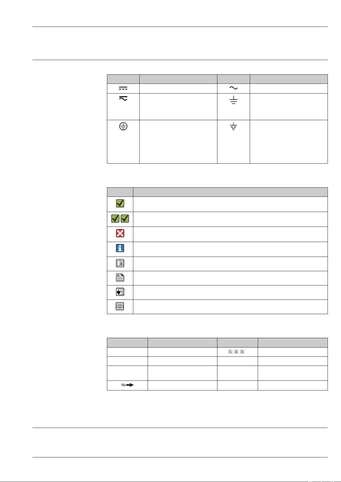
Direct measurement of the methane fraction (CH4)
The sound velocity, temperature and chemical composition of a gas are directly dependant on each
other. If two of these characteristic quantities are known, the third can be calculated. The higher the
gas temperature or the methane fraction, the higher the sound velocity in biogas.
Since the measuring device accurately measures both the sound velocity and the current gas
temperature, the methane fraction can be calculated directly and displayed on site without the need
for an additional measuring instrument → 1, 4.
The relative humidity of biogas is usually 100%. Thus, the water content can be determined by the
temperature measurement and can be compensated for.
The measuring device is unique in its ability to measure the methane fraction directly, making it
possible to monitor the gas flow and gas quality 24/7. In this way, operators of a biogas plant, for
example, can react swiftly and specifically to problems in the digestion process.
1 Calculation of the methane fraction [%] based on the sound velocity [m/s (ft/s)] and a temperature T of
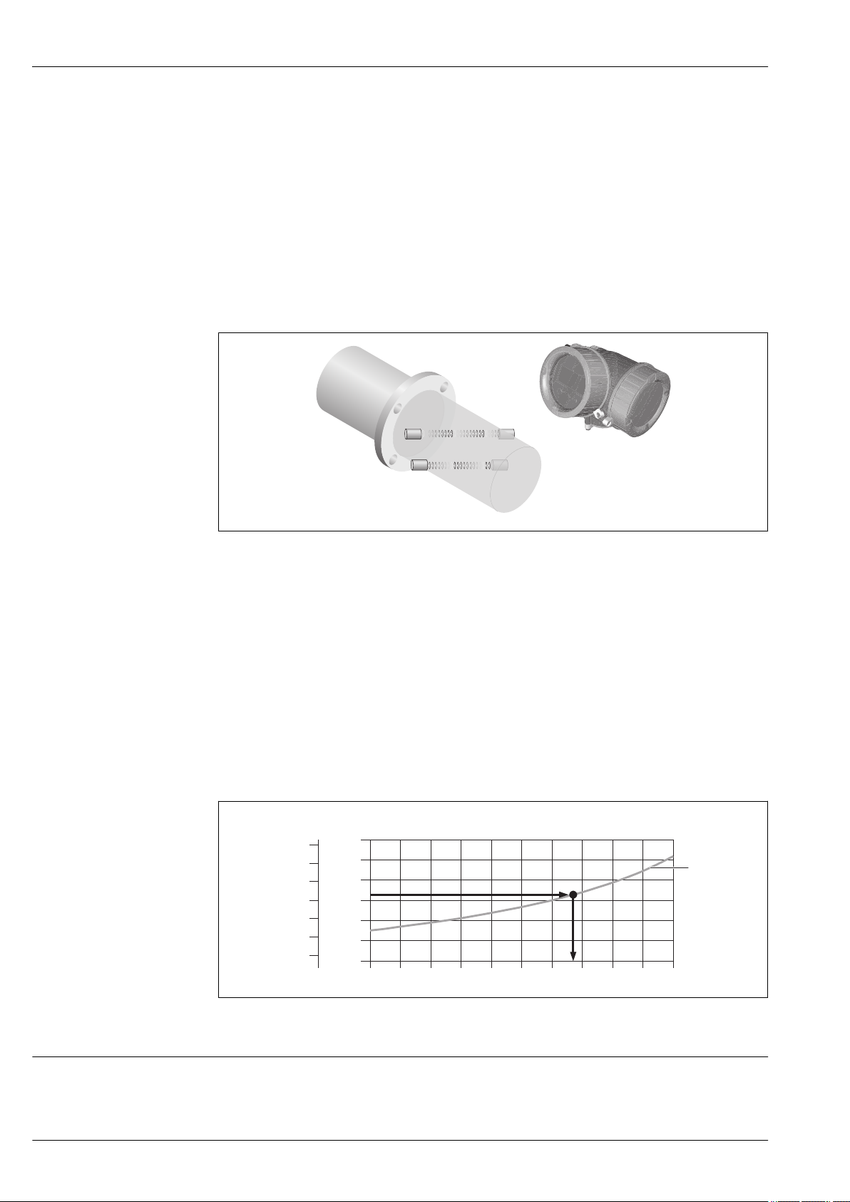
Measuring system
The device consists of a transmitter and a sensor.
The device is available as a compact version:
The transmitter and sensor form a mechanical unit.
4 Endress+Hauser
40 °C (104 °F), for example.
A0016160
Page 5
Proline Prosonic Flow B 200
Transmitter
Prosonic Flow 200 Device versions and materials:
• Compact, aluminum coated:
Aluminum, AlSi10Mg, coated
• Compact, stainless:
For maximum corrosion resistance: stainless steel 1.4404 (316L)
Configuration:
• External operation via four-line, illuminated local display with touch
A0013471
control and guided menus ("Make-it-run" wizards) for applications
• Via operating tools (e.g. FieldCare)
Sensor
Prosonic Flow B • Designed exclusively to measure:
Single-path version: DN 50 (2"),
DN 80 (3")
A0015826
Two-path version: DN 100 to 200
(4 to 8")
– Biogas
– Firedamp
– Air
– Methane
– Nitrogen
– Gas with a very high methane fraction
• Range of nominal diameter: DN 50 to 200 (2 to 8")
• Materials:
– Sensor:
Stainless steel 1.4404 (316L), cold worked
Stainless steel 1.4435 (316L), cold worked
– Process connections:
Stainless steel 1.4301 (304),
Stainless steel 1.4306 (304L),
Stainless steel 1.4404 (316L),
Steel S235JR,
Carbon steel A105
Input
Measured variable Direct measured variables
Volume flow
Calculated measured variables
• Corrected volume flow
• Mass flow
Optional measured variables (can be ordered)
Order code for "Sensor version", option 2 "Volume flow + Biogas analysis"
• Corrected methane volume flow
• Energy flow
• Methane fraction
• Gross calorific value
• Wobbe index
• Temperature
A0015452
Endress+Hauser 5
Page 6
Proline Prosonic Flow B 200
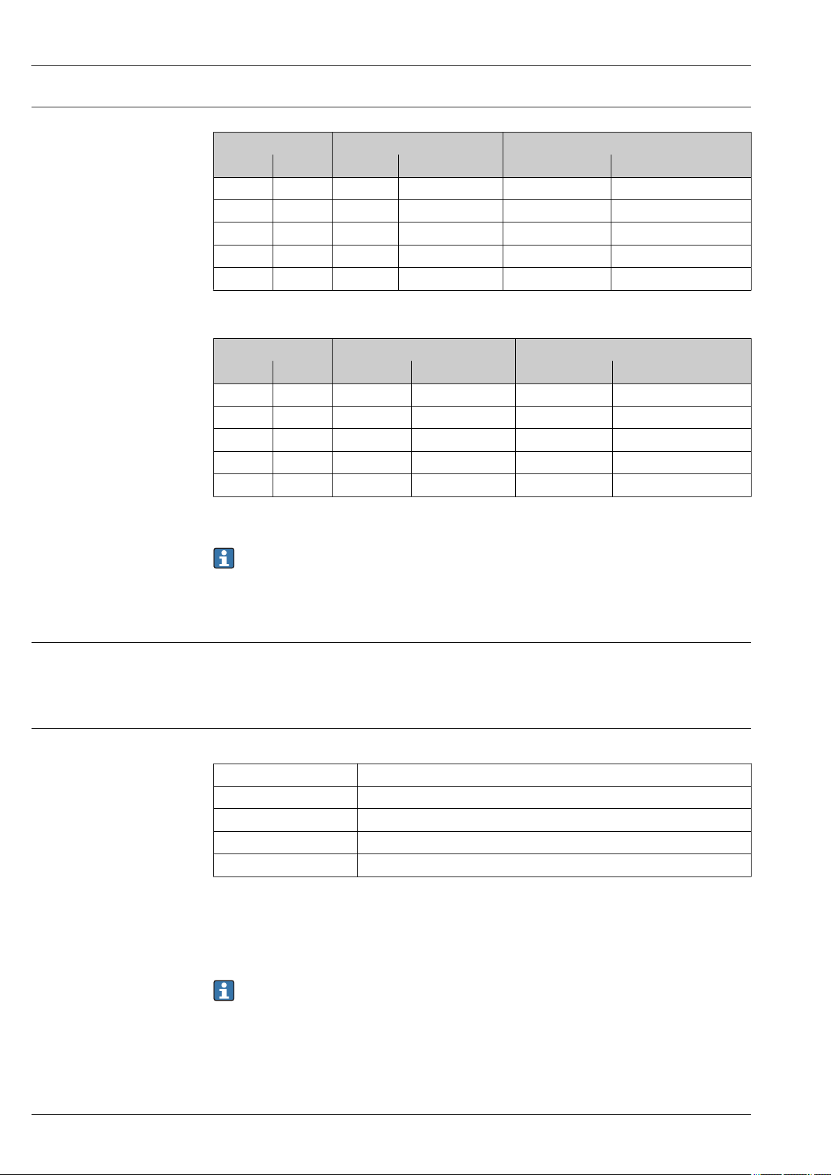
Measuring range
Standard (order code for "Calibration flow", option 1 "Operable flow range 30 : 1")
Nominal diameter Velocity Effective volume flow
[mm] [in] [m/s] [ft/s] [m3/h] [ft3/h]
50 2 1 to 30 3.28 to 98.4 9 to 269 316 to 9 495
80 3 1 to 30 3.28 to 98.4 20 to 611 720 to 21 592
100 4 1 to 30 3.28 to 98.4 34 to 1 032 1 215 to 36 443
150 6 1 to 30 3.28 to 98.4 76 to 2 290 2 695 to 80 862
200 8 1 to 30 3.28 to 98.4 131 to 3 925 4 620 to 138 596
Optional (order code for "Calibration flow", option 2 "Operable flow range 100 : 1")
Nominal diameter Velocity Effective volume flow
[mm] [in] [m/s] [ft/s] [m3/h] [ft3/h]
50 2 0.3 to 30 0.98 to 98.4 3 to 269 95 to 9 495
80 3 0.3 to 30 0.98 to 98.4 6 to 611 215 to 21 592
100 4 0.3 to 30 0.98 to 98.4 11 to 1 032 363 to 36 443
150 6 0.3 to 30 0.98 to 98.4 25 to 2 290 805 to 80 862
200 8 0.3 to 30 0.98 to 98.4 43 to 3 925 1 365 to 138 596
The values in the table should be regarded as reference values.
To calculate the measuring range, use the Applicator sizing tool → 48
Recommended measuring range
"Flow limit" section → 28
Operable flow range
• 30 : 1 (standard; order code for "Calibration Flow", option 1 "Operable flow range 30 : 1")
• 100 : 1 (optional; order code for "Calibration Flow", option 2 "Operable flow range 100 : 1")
Flow rates above the preset full scale value do not overload the amplifier so the totalized values are
registered correctly.
Input signal Current input
Current input 4-20 mA (passive)
Resolution 1 µA
Voltage drop Typically: 2.2 to 3 V for 3.6 to 22 mA
Maximum voltage ≤35 V
Possible input variables Pressure
External measured values
To increase the accuracy of certain measured variables, the automation system can continuously
write the operating pressure to the measuring device. Endress+Hauser recommends the use of a
pressure measuring device for absolute pressure, e.g. Cerabar M or Cerabar S
Various pressure transmitters can be ordered from Endress+Hauser: see "Accessories" section
→ 48
It is recommended to read in external measured values to calculate the following measured variables:
• Energy flow
• Mass flow
• Corrected volume flow
• Corrected methane volume flow
6 Endress+Hauser
Page 7

Proline Prosonic Flow B 200
Current input
The measured values are written from the automation system to the measuring device via the
current input → 6.
HART protocol
The measured values are written from the automation system to the measuring device via the HART
protocol. The pressure transmitter must support the following protocol-specific functions:
• HART protocol
• Burst mode
Output
Output signal Current output
Current output 1 4-20 mA HART (passive)
Current output 2 4-20 mA (passive)
Resolution < 1 µA
Damping Adjustable: 0.0 to 999.9 s
Assignable measured
variables
• Volume flow
• Corrected volume flow
• Corrected methane volume flow
• Mass flow
• Energy flow
• Methane fraction
• Calorific value
• Wobbe index
• Temperature
Pulse/frequency/switch output
Function Can be set to pulse, frequency or switch output
Version Passive, open collector
Maximum input values • DC 35 V
• 50 mA
For information on the Ex connection values → 10
Voltage drop • For ≤ 2 mA: 2 V
• For 10 mA: 8 V
Residual current ≤ 0.05 mA
Pulse output
Pulse width Adjustable: 5 to 2 000 ms
Maximum pulse rate 100 Impulse/s
Pulse value Adjustable
Assignable measured
variables
Frequency output
Output frequency Adjustable: 0 to 1 000 Hz
Damping Adjustable: 0 to 999 s
Pulse/pause ratio 1:1
• Volume flow
• Corrected volume flow
• Corrected methane volume flow
• Mass flow
• Energy flow
Endress+Hauser 7
Page 8

Proline Prosonic Flow B 200
Assignable measured
variables
Switch output
Switching behavior Binary, conductive or non-conductive
Switching delay Adjustable: 0 to 100 s
Number of switching
cycles
Assignable functions • Off
• Volume flow
• Corrected volume flow
• Corrected methane volume flow
• Mass flow
• Energy flow
• Methane fraction
• Calorific value
• Wobbe index
• Temperature
Unlimited
• On
• Diagnostic behavior
• Limit value
– Volume flow
– Corrected volume flow
– Corrected methane volume flow
– Mass flow
– Energy flow
– Methane fraction
– Calorific value
– Wobbe index
– Temperature
– Totalizer 1 to 3
• Flow direction monitoring
• Status
Low flow cut off
Signal on alarm
Depending on the interface, failure information is displayed as follows:
Current output
4-20 mA
Failure mode Selectable (as per NAMUR recommendation NE 43):
• Minimum value: 3.6 mA
• Maximum value: 22 mA
• Defined value: 3.59 to 22.5 mA
• Actual value
• Last valid value
HART
Device diagnostics Device condition can be read out via HART Command 48
Pulse/frequency/switch output
Pulse output
Failure mode Choose from:
• Actual value
• No pulses
Frequency output
Failure mode Choose from:
• Actual value
• 0 Hz
• Defined value: 0 to 1 250 Hz
8 Endress+Hauser
Page 9
Proline Prosonic Flow B 200
0
100
200
300
400
500
14
16 18 20
22 24
26 28 30 32
U [V]
s
R [ ]bW
600
220
16.8 23
34 36
1.1 1.21
35
Switch output
Failure mode Choose from:
• Current status
• Open
• Closed
Local display
Plain text display With information on cause and remedial measures
Backlight Additionally for device version with SD03 local display: red lighting indicates a
device error.
Status signal as per NAMUR recommendation NE 107
Operating tool
• Via digital communication:
HART protocol
• Via service interface
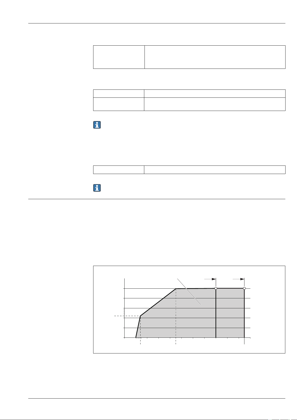
Load
Plain text display With information on cause and remedial measures
Additional information on remote operation → 42
Load for current output: 0 to 500 Ω, depending on the external supply voltage of the power supply
unit
Calculation of the maximum load
Depending on the supply voltage of the power supply unit (US), the maximum load (RB) including
line resistance must be observed to ensure adequate terminal voltage at the device. In doing so,
observe the minimum terminal voltage
• For US = 16.0 to 16.8 V: RB ≤ (US - 16.0 V): 0.0036 A
• For US = 16.8 to 23.0 V: RB ≤ (US - 12.0 V): 0.022 A
• For US = 23.0 to 30.0 V: RB ≤ 500 Ω
1 Operating range
1.1 For order code for "Output", option A "4-20 mA HART"/option B "4-20 mA HART, pulse/frequency/switch
output" with Ex i and option C "4-20 mA HART + 4-20 mA analog"
1.2 For order code for "Output", option A "4-20 mA HART"/option B "4-20 mA HART, pulse/frequency/switch
output" with non-Ex and Ex d
Endress+Hauser 9
A0018972
Page 10

Sample calculation
Supply voltage of the power supply unit: US = 17.5 V
Maximum load: RB ≤ (17.5 V - 12.0 V): 0.022 A = 250 Ω
Ex connection data Safety-related values
Type of protection Ex d
Order code for "Output" Output type Safety-related values
Option A 4-20mA HART U
Option B 4-20mA HART U
Option C 4-20mA HART
Option D 4-20mA HART U
Proline Prosonic Flow B 200
Pulse/frequency/switch output U
4-20mA analog
Pulse/frequency/switch output U
4 to 20 mA current input U
nom
U
max
nom
U
max
nom
U
max
P
max
U
nom
U
max
nom
U
max
nom
U
max
P
max
nom
U
max
= DC 35 V
= 250 V
= DC 35 V
= 250 V
= DC 35 V
= 250 V
1)
= 1 W
= DC 30 V
= 250 V
= DC 35 V
= 250 V
= DC 35 V
= 250 V
1)
= 1 W
= DC 35 V
= 250 V
1) Internal circuit limited by Ri = 760.5 Ω
Type of protection XP
Order code for "Output" Output type Safety-related values
Option A 4-20mA HART U
Option B 4-20mA HART U
Pulse/frequency/switch output U
Option C 4-20mA HART
4-20mA analog
Option D 4-20mA HART U
Pulse/frequency/switch output U
4 to 20 mA current input U
1) Internal circuit limited by Ri = 760.5 Ω
nom
U
max
nom
U
max
nom
U
max
P
max
U
nom
U
max
nom
U
max
nom
U
max
P
max
nom
U
max
= DC 35 V
= 250 V
= DC 35 V
= 250 V
= DC 35 V
= 250 V
1)
= 1 W
= DC 30 V
= 250 V
= DC 35 V
= 250 V
= DC 35 V
= 250 V
1)
= 1 W
= DC 35 V
= 250 V
10 Endress+Hauser
Page 11

Proline Prosonic Flow B 200
Type of protection NI
Order code for "Output" Output type Safety-related values
Option A 4-20mA HART U
Option B 4-20mA HART U
Pulse/frequency/switch output U
Option C 4-20mA HART
4-20mA analog
Option D 4-20mA HART U
Pulse/frequency/switch output U
4 to 20 mA current input U
nom
U
max
nom
U
max
nom
U
max
P
max
U
nom
U
max
nom
U
max
nom
U
max
P
max
nom
U
max
= DC 35 V
= 250 V
= DC 35 V
= 250 V
= DC 35 V
= 250 V
1)
= 1 W
= DC 30 V
= 250 V
= DC 35 V
= 250 V
= DC 35 V
= 250 V
1)
= 1 W
= DC 35 V
= 250 V
1) Internal circuit limited by Ri = 760.5 Ω
Type of protection NIFW
Order code for "Output" Output type Safety-related values
Option A 4-20mA HART Ui = DC 35 V
Ii = n.a.
Pi = 1 W
Li = 0 μH
Ci = 5 nF
Option B 4-20mA HART Ui = DC 35 V
Ii = n.a.
Pi = 1 W
Li = 0 μH
Ci = 5 nF
Pulse/frequency/switch output Ui = DC 35 V
Ii = n.a.
Pi = 1 W
Li = 0 μH
Ci = 6 nF
4-20mA HART Ui = DC 30 V
Ii = n.a.
Pi = 1 W
Li = 0 μH
Ci = 30 nF
Ii = n.a.
Pi = 1 W
Li = 0 μH
Ci = 5 nF
Option C
Option D
4-20mA analog
4-20mA HART Ui = DC 35 V
Endress+Hauser 11
Page 12

Proline Prosonic Flow B 200
Order code for "Output" Output type Safety-related values
Pulse/frequency/switch output Ui = DC 35 V
Ii = n.a.
Pi = 1 W
Li = 0 μH
Ci = 6 nF
4 to 20 mA current input Ui = DC 35 V
Ii = n.a.
Pi = 1 W
Li = 0 μH
Ci = 5 nF
Intrinsically safe values
Type of protection Ex ia
Order code for "Output" Output type Intrinsically safe values
Option A 4-20mA HART Ui = DC 30 V
Ii = 300 mA
Pi = 1 W
Li = 0 μH
Ci = 5 nF
Option B 4-20mA HART Ui = DC 30 V
Ii = 300 mA
Pi = 1 W
Li = 0 μH
Ci = 5 nF
Pulse/frequency/switch output Ui = DC 30 V
Ii = 300 mA
Pi = 1 W
Li = 0 μH
Ci = 6 nF
Option C 4-20mA HART Ui = DC 30 V
4-20mA analog
Option D 4-20mA HART Ui = DC 30 V
Pulse/frequency/switch output Ui = DC 30 V
4 to 20 mA current input Ui = DC 30 V
Ii = 300 mA
Pi = 1 W
Li = 0 μH
Ci = 30 nF
Ii = 300 mA
Pi = 1 W
Li = 0 μH
Ci = 5 nF
Ii = 300 mA
Pi = 1 W
Li = 0 μH
Ci = 6 nF
Ii = 300 mA
Pi = 1 W
Li = 0 μH
Ci = 5 nF
12 Endress+Hauser
Page 13

Proline Prosonic Flow B 200
Type of protection IS
Order code for "Output" Output type Intrinsically safe values
Option A 4-20mA HART Ui = DC 30 V
Ii = 300 mA
Pi = 1 W
Li = 0 μH
Ci = 5 nF
Option B 4-20mA HART Ui = DC 30 V
Ii = 300 mA
Pi = 1 W
Li = 0 μH
Ci = 5 nF
Pulse/frequency/switch output Ui = DC 30 V
Ii = 300 mA
Pi = 1 W
Li = 0 μH
Ci = 6 nF
Option C 4-20mA HART Ui = DC 30 V
4-20mA analog
Option D 4-20mA HART Ui = DC 30 V
Pulse/frequency/switch output Ui = DC 30 V
4 to 20 mA current input Ui = DC 30 V
Ii = 300 mA
Pi = 1 W
Li = 0 μH
Ci = 30 nF
Ii = 300 mA
Pi = 1 W
Li = 0 μH
Ci = 5 nF
Ii = 300 mA
Pi = 1 W
Li = 0 μH
Ci = 6 nF
Ii = 300 mA
Pi = 1 W
Li = 0 μH
Ci = 5 nF
Low flow cut off
Galvanic isolation
The switch points for low flow cut off are user-selectable.
All outputs are galvanically isolated from one another.
Protocol-specific data HART
Manufacturer ID 0x11
Device type ID 0x5A
HART protocol revision 7
Device description files
(DTM, DD)
HART load • Min. 250 Ω
Information and files under:
www.endress.com
• Max. 500 Ω
Endress+Hauser 13
Page 14

Proline Prosonic Flow B 200
Dynamic variables Read out the dynamic variables: HART command 3
The measured variables can be freely assigned to the dynamic variables.
Measured variables for PV (primary dynamic variable)
• Volume flow
• Corrected volume flow
• Corrected methane volume flow
• Energy flow
• Methane fraction in %
• Calorific value
• Wobbe index
• Temperature
• Mass flow
• Sound velocity
• Flow velocity
• Acceptance rate
• Signal asymmetry
• Turbulence
• Signal to noise ratio
• Signal strength
Measured variables for SV, TV, QV (secondary, tertiary and quaternary
dynamic variable)
• Volume flow
• Corrected volume flow
• Corrected methane volume flow
• Energy flow
• Methane fraction in %
• Calorific value
• Wobbe index
• Temperature
• Totalizer 1
• Totalizer 2
• Totalizer 3
• Mass flow
• Sound velocity
• Flow velocity
• Acceptance rate
• Signal asymmetry
• Turbulence
• Signal to noise ratio
• Signal strength
Device variables Read out the device variables: HART command 9
The device variables are permanently assigned.
A maximum of 8 device variables can be transmitted:
• 0 = volume flow
• 1 = corrected volume flow
• 2 = methane corrected volume flow
• 3 = energy flow
• 4 = methane fraction in %
• 5 = calorific value
• 6 = Wobbe index
• 7 = temperature
• 8 = totalizer 1
• 9 = totalizer 2
• 10 = totalizer 3
• 11 = mass flow
• 12 = sound velocity
• 13 = flow velocity
• 14 = acceptance rate
• 15 = signal asymmetry
• 16 = turbulence
• 17 = signal to noise ratio
• 18 = signal strength
14 Endress+Hauser
Page 15
Proline Prosonic Flow B 200
–
4
+
1
–
2
+
3
1
2
4
–
6
+
5
3
+
1
–
2
–
4
+
3
–
6
+
5
3
1
2
4
Power supply
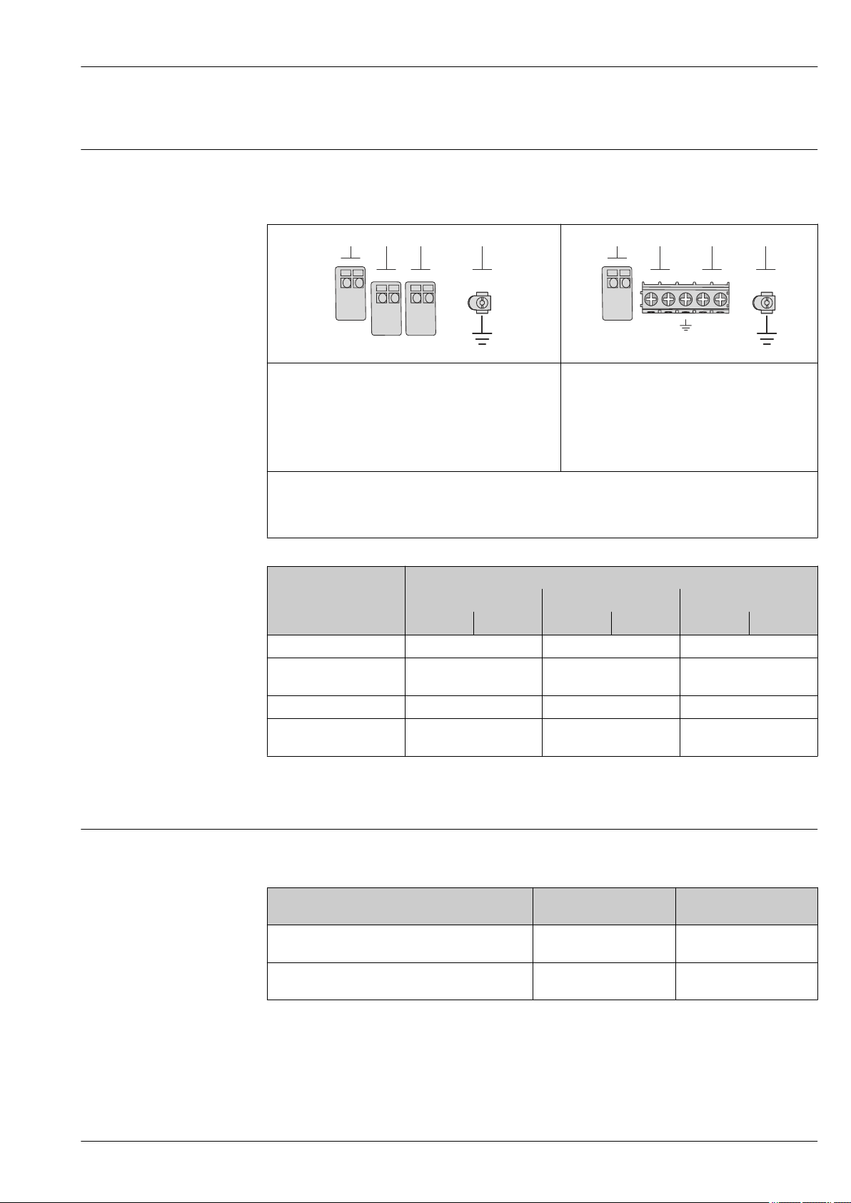
Terminal assignment Transmitter
Connection versions
A0020738
Maximum number of terminals
Terminals 1 to 6:
Without integrated overvoltage protection
1
Output 1 (passive): supply voltage and signal transmission
2
Output 2 (passive): supply voltage and signal transmission
3
Input (passive): supply voltage and signal transmission
4
Ground terminal for cable shield
Order code for "Output" Terminal numbers
Output 1 Output 2 Input
1 (+) 2 (-) 3 (+) 4 (-) 5 (+) 6 (-)
Option A 4-20 mA HART (passive) - -
Option B
Option C
Option D
1)
1)
1) 2)
4-20 mA HART (passive)
4-20 mA HART (passive) 4-20 mA analog (passive) -
4-20 mA HART (passive)
Maximum number of terminals for order code for
"Accessory mounted", option NA "Overvoltage
protection"
• Terminals 1 to 4:
With integrated overvoltage protection
• Terminals 5 to 6:
Without integrated overvoltage protection
Pulse/frequency/switch
output (passive)
Pulse/frequency/switch
output (passive)
A0020739
-
4-20 mA current input
(passive)
1) Output 1 must always be used; output 2 is optional.
2) The integrated overvoltage protection is not used with option D: Terminals 5 and 6 (current input) are not
protected against overvoltage.
Supply voltage Transmitter
An external power supply is required for each output.
Order code for "Output"
Option A
Option B : 4-20 mA HART, pulse/frequency/switch
output
Endress+Hauser 15
1) 2)
: 4-20 mA HART • For 4 mA: ≥ DC 16 V
Minimum
terminal voltage
• For 20 mA: ≥ DC 12 V
• For 4 mA: ≥ DC 16 V
• For 20 mA: ≥ DC 12 V
Maximum
terminal voltage
DC 35 V
DC 35 V
Page 16
Proline Prosonic Flow B 200
Order code for "Output"
Option C : 4-20 mA HART + 4-20 mA analog • For 4 mA: ≥ DC 16 V
Option D: 4-20 mA HART, pulse/frequency/switch
output, 4-20 mA current input
1) External supply voltage of the power supply unit with load.
2) For device versions with SD03 local display: The terminal voltage must be increased by DC 2 V if
backlighting is used.
3) Voltage drop 2.2 to 3 V for 3.59 to 22 mA
For information about the load see → 9
Various power supply units can be ordered from Endress+Hauser: see "Accessories" section
→ 48
For information on the Ex connection values → 10
Power consumption Transmitter
Order code for "Output" Maximum power consumption
Option A: 4-20 mA HART 770 mW
Option B: 4-20 mA HART, pulse/
frequency/switch output
Option C: 4-20 mA HART + 4-20 mA
analog
Option D: 4-20 mA HART, pulse/
frequency/switch output, 4-20 mA current
input
Minimum
terminal voltage
• For 20 mA: ≥ DC 12 V
3)
• Operation with output 1: 770 mW
• Operation with output 1 and 2: 2 770 mW
• Operation with output 1: 660 mW
• Operation with output 1 and 2: 1 320 mW
• Operation with output 1: 770 mW
• Operation with output 1 and 2: 2770 mW
• Operation with output 1 and input: 840 mW
• Operation with output 1, 2 and input: 2840 mW
≥ DC 12 V
Maximum
terminal voltage
DC 30 V
DC 35 V
For information on the Ex connection values → 10
Current consumption Current output
For every 4-20 mA or 4-20 mA HART current output: 3.6 to 22.5 mA
If the option Defined value is selected in the Failure mode parameter : 3.59 to 22.5 mA
Current input
3.59 to 22.5 mA
Internal current limiting: max. 26 mA
Power supply failure
• Totalizers stop at the last value measured.
• Configuration is retained in the device memory (HistoROM).
• Error messages (incl. total operated hours) are stored.
16 Endress+Hauser
Page 17

Proline Prosonic Flow B 200
1
2
2
3
4...20 mA
41
+
-
5
+
-
2
4...20 mA
3
1
+
-
4
+
–
+
-
Electrical connection Connecting the transmitter
1 Cable entry for output 1
2 Cable entry for output 2
Connection examples
Current output 4-20 mA HART
A0015510
A0015511
2 Connection example for 4-20 mA HART current output (passive)
1 Automation system with current input (e.g. PLC)
2 Active barrier for power supply with integrated resistor for HART communication (≥ 250 Ω)(e.g. RN221N)
Connection for HART operating devices → 42
Observe the maximum load → 9
3 Cable shield, observe cable specifications
4 Analog display unit: observe maximum load → 9
5 Transmitter
Current output 4-20 mA
A0015512
3 Connection example for 4-20 mA current output (passive)
1 Automation system with current input (e.g. PLC)
2 Active barrier for power supply (e.g. RN221N)
3 Analog display unit: observe maximum load → 9
4 Transmitter
Endress+Hauser 17
Page 18

Pulse/frequency output
1
+
_
12345
2
+
–
+
–
3
1
+
_
+
_
2
+
_
3
1
+
-
3
+
-
2
4 Connection example for pulse/frequency output (passive)
1 Automation system with pulse/frequency input (e.g. PLC)
2 Power supply
3 Transmitter: observe input values
Switch output
Proline Prosonic Flow B 200
A0016801
5 Connection example for switch output (passive)
1 Automation system with switch input (e.g. PLC)
2 Power supply
3 Transmitter: observe input values
Current input
6 Connection example for 4-20 mA current input
1 Power supply
2 External measuring device (for capturing the pressure)
3 Transmitter: observe input values → 6
A0016802
A0020741
18 Endress+Hauser
Page 19

Proline Prosonic Flow B 200
3
4...20 mA
5
1
+
-
3
6
+
–
+
+
–
+
–
+
–
+
–
–
2
4
4
7
+
-
HART input
A0016029
7 Connection example for HART input with a common negative
1 Automation system with HART output (e.g. PLC)
2 Resistor for HART communication (≥ 250 Ω): observe maximum load → 9
3 Active barrier for power supply (e.g. RN221N)
4 Cable shield, observe cable specifications
5 Analog display unit: observe maximum load → 9
6 Pressure transmitter (e.g. Cerabar M, Cerabar S): see requirements
7 Transmitter
Potential equalization Requirements
No special measures for potential equalization are required.
For devices intended for use in hazardous locations, please observe the guidelines in the Ex
documentation (XA).
Terminals
• For device version without integrated overvoltage protection: plug-in spring terminals for wire
cross-sections 0.5 to 2.5 mm2 (20 to 14 AWG)
• For device version with integrated overvoltage protection: screw terminals for wire cross-sections
0.2 to 2.5 mm2 (24 to 14 AWG)
Cable entries
• Cable gland (not for Ex d): M20 × 1.5 with cable 6 to 12 mm (0.24 to 0.47 in)
• Thread for cable entry:
– For non-Ex and Ex: NPT ½"
– For non-Ex and Ex (not for CSA Ex d/XP): G ½"
– For Ex d: M20 × 1.5
Cable specification Permitted temperature range
• –40 °C (–40 °F) to +80 °C (+176 °F)
• Minimum requirement: cable temperature range ≥ ambient temperature +20 K
Signal cable
Current output
• For 4-20 mA: standard installation cable is sufficient.
• For 4-20 mA HART: Shielded cable recommended. Observe grounding concept of the plant.
Pulse/frequency/switch output
Standard installation cable is sufficient.
Current input
Standard installation cable is sufficient.
Endress+Hauser 19
Page 20

Proline Prosonic Flow B 200
Overvoltage protection
Reference operating conditions
The device can be ordered with integrated overvoltage protection for diverse approvals:
Order code for "Accessory mounted", option NA "Overvoltage protection"
Input voltage range Values correspond to supply voltage specifications
Resistance per channel 2 ⋅ 0.5 Ω max
DC sparkover voltage 400 to 700 V
Trip surge voltage < 800 V
Capacitance at 1 MHz < 1.5 pF
Nominal discharge current
(8/20 μs)
Temperature range –40 to +85 °C (–40 to +185 °F)
1) The voltage is reduced by the amount of the internal resistance I
10 kA
min
⋅ R
i
1)
Depending on the temperature class, restrictions apply to the ambient temperature for device
versions with overvoltage protection → 25
Performance characteristics
• Error limits following ISO/DIS 11631
• Calibration gas: air
• Temperature regulated to 24 ± 0.5 °C (75.2 ± 0.9 °F) under atmospheric pressure
• Humidity regulated to <40% RH
• Accuracy based on accredited calibration rigs that are traced to ISO 17025.
To calculate the measuring range, use the Applicator sizing tool → 48
Maximum measured error
o.r. = of reading; o.f.s. = of full scale value; abs. = absolute; T = medium temperature
Volume flow
Standard
Order code for "Calibration flow", option 1
"Operable flow range 30 : 1"
Optional
Order code for "Calibration flow", option 2
"Operable flow range 100 : 1"
• ±1.5 % o.r. for 3 to 30 m/s (9.84 to 98.4 ft/s)
• ±3 % o.r. for 1 to 3 m/s (3.28 to 9.84 ft/s)
• ±0.1 % o.f.s. for 0.3 to 1 m/s (0.98 to 3.28 ft/s)
• ±1.5 % o.r. for 1 to 30 m/s (3.28 to 98.4 ft/s)
Methane
±2 % o.f.s. = ±2 % abs.
Temperature
±0.6 % ± 0.005 · T °C (±0.9 °F ± 0.005 · (T – 32) °F)
20 Endress+Hauser
Page 21

Proline Prosonic Flow B 200
0
[%]
2.0
1.0
0
5
v
[m/s]
[ft/s]
3.0
4.0
30
0
5 10 15 100
5.0
6.0
7.0
8.0
9.0
10.0
2
1
20
25
1 2 3 4
6
7 8
Example for max. measured error (volume flow)
A0015541
8 Example for max. measured error (volume flow) in % o.r.
1 Standard (order code for "Calibration flow", option 1 "Operable flow range 30 : 1")
2 Optional (order code for "Calibration flow", option 2 "Operable flow range 100 : 1")
Accuracy of outputs
o.r. = of reading
The outputs have the following base accuracy specifications.
Current output
Accuracy ±10 µA
Pulse/frequency output
Accuracy Max. ±100 ppm o.r.
Repeatability
o.r. = of reading; o.f.s. = of full scale value; abs. = absolute; T = medium temperature
Volume flow
±0.5 % o.r.
Methane
±0.5 % o.f.s. = ±0.5 % abs.
Temperature
±0.3 °C ± 0.0025 × T °C (±0.45 °F ± 0.0025 × (T – 32) °F)
Response time
• The response time depends on the configuration (damping).
• Response time in the event of erratic changes in the flow: after 1 000 ms 95% of the full scale
Influence of ambient
value.
o.r. = of reading
temperature
Current output
Additional error, in relation to the span of 16 mA:
Endress+Hauser 21
Page 22

Proline Prosonic Flow B 200
Mounting location
Temperature coefficient at
zero point (4 mA)
Temperature coefficient
with span (20 mA)
0.02 %/10 K
0.05 %/10 K
Pulse/frequency output
Temperature coefficient Max. ±100 ppm o.r.
Installation
No special measures such as supports are necessary. External forces are absorbed by the construction
of the device.
Orientation
A0015543
The direction of the arrow on the sensor helps you to install the sensor according to the flow
direction (direction of medium flow through the piping).
• Install the measuring device in a parallel plane free of external mechanical stress.
• The internal diameter of the pipe must match the internal diameter of the sensor .
A0015895
Orientation Compact version
A Vertical orientation
A0015545
B Horizontal orientation, transmitter
head up *
A0015589
22 Endress+Hauser
Page 23

Proline Prosonic Flow B 200
0°
+3°
–3°
0°
+3°
–3°
20 × DN 3 × DN
1
3
2
4
20 × DN 3 × DN
20 × DN 3 × DN20 × DN 3 × DN
Orientation Compact version
C Horizontal orientation, transmitter
head down *
A0015590
D Horizontal orientation, transmitter
head at side
A0015592
* A maximum deviation of only ±3° is permitted for the horizontal alignment of the converters.
A0016534
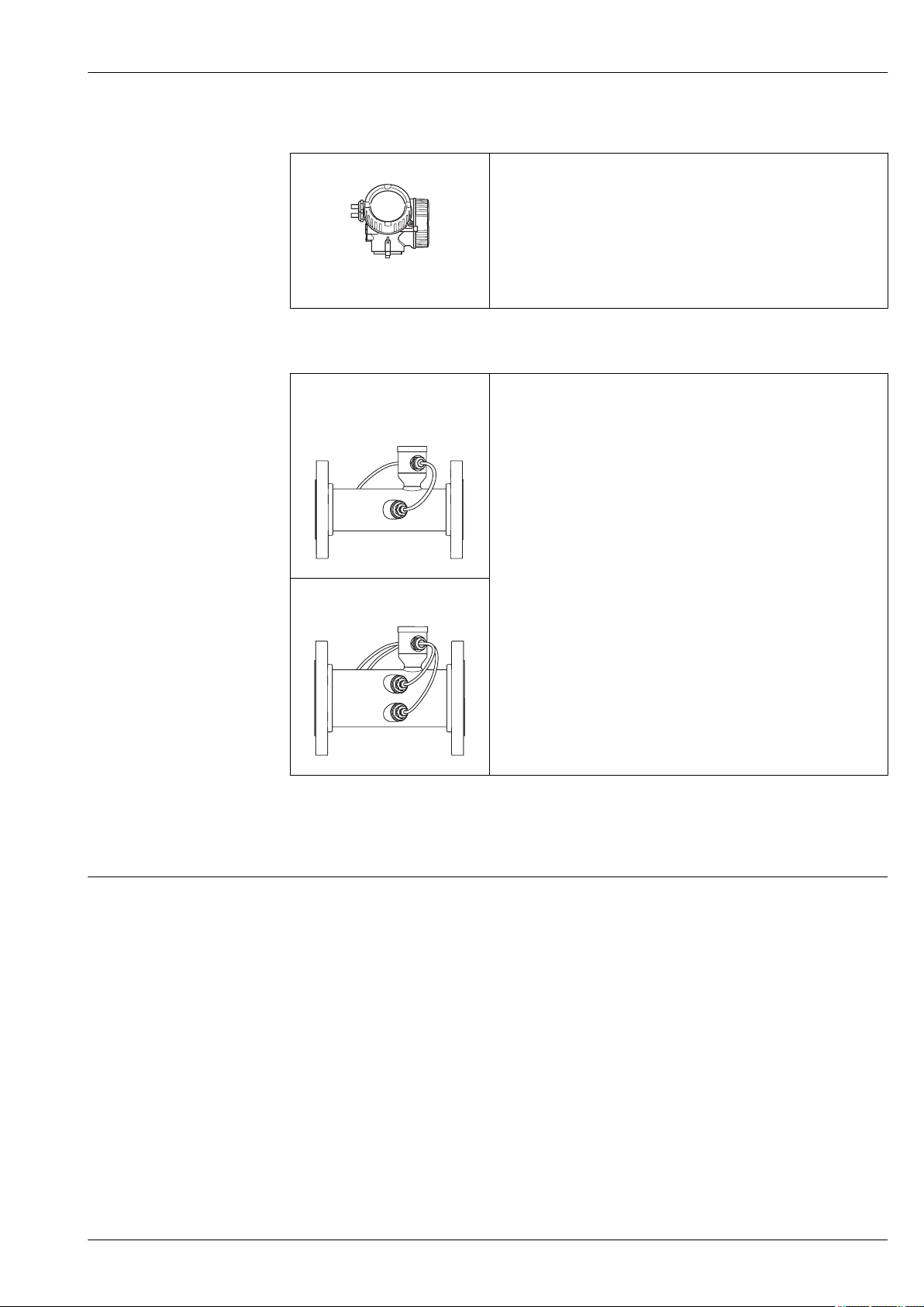
Inlet and outlet runs
If possible, the sensor should be installed upstream from valves, T-pieces, elbows etc. To attain the
specified level of accuracy of the measuring device, the below mentioned inlet and outlet runs must
be maintained at minimum. If there are several flow disturbances present, the longest specified inlet
run must be maintained.
Single-path version: DN 50 (2"), DN 80 (3")
A0015453
9 Single-path version: minimum inlet and outlet runs with various flow obstructions
1 90 ° elbow or T-section
2 Pump
3 2 × 90 ° elbow, 3-dimensional
4 Control valve
Endress+Hauser 23
Page 24

Proline Prosonic Flow B 200
10 × DN 3 × DN
1
3
2
4
10 × DN 3 × DN
10 × DN 3 × DN10 × DN 3 × DN
3 × DN
PT
8 × DN
10 × DN
2 × DN
1
Two-path version: DN 100 to 200 (4 to 8")
10 Two-path version: minimum inlet and outlet runs with various flow obstructions
1 90 ° elbow or T-section
2 Pump
3 2 × 90 ° elbow, 3-dimensional
4 Control valve
A0015553
Special mounting instructions
Outlet runs when installing external devices
If installing an external device, observe the specified distance.
A0015901
PT Pressure transmitter
Flow conditioner
If the inlet runs cannot be observed, the use of a flow conditioner is recommended. This makes the
following shorter inlet runs possible:
Single-path version Two-path version
10 × DN 5 × DN
The flow conditioner should divide the inlet run available into a ratio of around 20 : 80. Example of
an inlet run of 10 × DN:
1 Flow conditioner
Pressure loss
The pressure loss for flow conditioners is calculated as follows:
∆p [mbar] = 0.0085 · ρ [kg/m3] · v2 [m/s]
24 Endress+Hauser
A0015562
Page 25

Proline Prosonic Flow B 200
Example for biogas
p = 1 040 mbar abs.
ρ = 1.0432 kg/m3 with t = 54 °C (129 °F)
v = 7 m/s
∆p = 0.0085 · 1.0432 kg/m3 · 49 m/s = 0.434 mbar
- - abs.: absolute
ρ : density of the process medium
v: average flow velocity
Environment
Ambient temperature range
Transmitter –40 to +60 °C (–40 to +140 °F)
Local display –20 to +60 °C (–4 to +140 °F), the readability of the display may be
impaired at temperatures outside the temperature range.
Sensor • Flange material carbon steel: –10 to +60 °C (+14 to +140 °F)
• Flange material stainless steel: –40 to +60 °C (–40 to +140 °F)
• Version without flange: –40 to +60 °C (–40 to +140 °F)
If operating outdoors:
‣
Avoid direct sunlight, particularly in warm climatic regions.
Weather protection covers can be ordered from Endress+Hauser: see "Accessories" section
→ 46
Temperature tables
The following interdependencies between the permitted ambient and fluid temperatures apply when
operating the device in hazardous areas:
The following applies for installations with overvoltage protection in conjunction with approval code
BJ or IJ: Ta = Ta - 2 °C (Ta = Ta - 3.6 °F)
Order code for "Output", option A "4-20mA HART"
Ex ia, Ex d, CCSAUS IS, CCSAUS XP, CCSAUS NI
SI units
Nominal diameter
[mm]
50 to 200 40 60 80 80 80 80 80
50 to 200 50 – 80 80 80 80 80
50 to 200 60 – 80 80 80 80 80
T
a
[°C]T6[85 °C]T5[100 °C]T4[135 °C]T3[200 °C]T2[300 °C]T1[450 °C]
US units
Nominal diameter
[in]
2 to 8 104 140 176 176 176 176 176
2 to 8 122 – 176 176 176 176 176
2 to 8 140 – 176 176 176 176 176
T
a
[°F]T6[185 °F]T5[212 °F]T4[275 °F]T3[392 °F]T2[572 °F]T1[842 °F]
Order code for "Output", option B "4-20mA HART, pulse/frequency/switch output"
Endress+Hauser 25
Page 26

Ex ia, Ex d, CCSAUS IS, CCSAUS XP, CCSAUS NI
SI units
Proline Prosonic Flow B 200
Nominal diameter
[mm]
50 to 200 40 –
50 to 200 50 – 60
T
a
[°C]T6[85 °C]T5[100 °C]T4[135 °C]T3[200 °C]T2[300 °C]T1[450 °C]
1)
80 80 80 80 80
2)
80 80 80 80
50 to 200 60 – – 80 80 80 80
1) Ta = 60 °C for pulse/frequency/switch output Pi ≤ 0.85 W
2) Ta = 80 °C for pulse/frequency/switch output Pi ≤ 0.85 W
US units
Nominal diameter
[in]
2 to 8 104 –
2 to 8 122 – 140
2 to 8 140 – – 176 176 176 176
1) Ta = 140 °F for pulse/frequency/switch output Pi ≤ 0.85 W
2) Ta = 176 °F for pulse/frequency/switch output Pi ≤ 0.85 W
T
a
[°F]T6[185 °F]T5[212 °F]T4[275 °F]T3[392 °F]T2[572 °F]T1[842 °F]
1)
176 176 176 176 176
2)
176 176 176 176
Order code for "Output", option C "4-20mA HART, 4-20mA analog"
Ex ia, Ex d, CCSAUS IS, CCSAUS XP, CCSAUS NI
SI units
Nominal diameter
[mm]
50 to 200 40 60 80 80 80 80 80
50 to 200 50 – 80 80 80 80 80
50 to 200 60 – 55 80 80 80 80
T
a
[°C]T6[85 °C]T5[100 °C]T4[135 °C]T3[200 °C]T2[300 °C]T1[450 °C]
US units
Nominal diameter
[in]
2 to 8 104 140 176 176 176 176 176
2 to 8 122 – 176 176 176 176 176
2 to 8 140 – 131 176 176 176 176
T
a
[°F]T6[185 °F]T5[212 °F]T4[275 °F]T3[392 °F]T2[572 °F]T1[842 °F]
Order code for "Output", option D "4-20mA HART, PFS output; 4-20 mA input"
26 Endress+Hauser
Page 27

Proline Prosonic Flow B 200
Ex ia, Ex d, CCSAUS IS, CCSAUS XP, CCSAUS NI
SI units
Nominal diameter
[mm]
50 to 200 35 60 80 80 80 80 80
50 to 200 50 – 80 80 80 80 80
50 to 200 60 – – 80 80 80 80
1) The following applies for installations with overvoltage protection in conjunction with temperature class
T5, T6 and approval options BA, BB, BD, BH, BJ, B2, IA, IB, ID, IH, IJ, I4, C2: Ta = Ta - 2 °C
1)
T
a
[ºC]T6[85 °C]T5[100 °C]T4[135 °C]T3[200 °C]T2[300 °C]T1[450 °C]
US units
Nominal diameter
[in]
2 to 8 95 140 176 176 176 176 176
2 to 8 122 – 176 176 176 176 176
2 to 8 140 – – 176 176 176 176
1)
T
a
[ºF]T6[185 °F]T5[212 °F]T4[275 °F]T3[392 °F]T2[572 °F]T1[842 °F]
Storage temperature
Degree of protection
Shock resistance
Vibration resistance
Electromagnetic compatibility (EMC)
1) The following applies for installations with overvoltage protection in conjunction with temperature class
T5, T6 and approval options BA, BB, BD, BH, BJ, B2, IA, IB, ID, IH, IJ, I4, C2: Ta = Ta - 35.6 °F
All components apart from the display modules:
–40 to +80 °C (–40 to +176 °F), preferably at +20 °C (+68 °F)
Display modules
–40 to +80 °C (–40 to +176 °F)
Transmitter
• As standard: IP66/67, type 4X enclosure
• When housing is open: IP20, type 1 enclosure
• Display module: IP20, type 1 enclosure
Sensor
IP66/67, type 4X enclosure
In accordance with EN 60721-3-4
Class 4M4, in accordance with EN 60721-3-4
• As per IEC/EN 61326 and NAMUR Recommendation 21 (NE 21)
• Complies with emission limits for industry as per EN 55011
For details, refer to the Declaration of Conformity.
Process
Medium temperature range
Pressure-temperature ratings
Endress+Hauser 27
Sensor
0 to +80 °C (+32 to +176 °F)
The following pressure-temperature ratings refer to the entire device and not just the process
connection.
Page 28

Proline Prosonic Flow B 200
[°C]0 20 40 60 80 100
80 200
[°F]
0
10
20
[bar][psi]
200
100
300
0
40 120 160
[°C]0 20 40 60 80 100
80 200
[°F]
0
10
20
[bar][psi]
200
100
300
0
40 120 160
[°C]0 20 40 60 80 100
80 200
[°F]
0
10
20
[bar][psi]
200
100
300
0
40 120 160
[°C]0 20 40 60 80 100
80 200
[°F]
0
10
20
[bar][psi]
200
100
300
0
40 120 160
Flange connection according to EN 1092-1 (DIN 2501)
11 With lap joint flange, stamped plate PN 10, material 1.4301 (304) (DN 50 to 200 / 2 to 8")
Flange connection according to EN 1092-1 (DIN 2501)
A0015905
A0015906
12 With lap joint flange PN 10, material 1.4306 (304L) (DN 200 / 8")
Flange connection according to EN 1092-1 (DIN 2501)
A0015932
13 With lap joint flange PN 10/16, materials S235JR (DN 50 to 200 / 2 to 8") and 1.4306 (304L) (DN 50 to
150 / 2 to 6"); With lap joint flange, stamped plate PN 10, material S235JR (DN 50 to 200 / 2 to 8")
Flange connection according to ASME B16.5
14 With lap joint flange Class 150, materials 1.4404 (316L) and A105 (DN 50 to 200 / 2 to 8")
Flow limit
28 Endress+Hauser
Select the nominal diameter by optimizing between the required flow range and permissible pressure
loss.
For an overview of the measuring range full scale values, see the "Measuring range" section
→ 6
A0015568
Page 29

Proline Prosonic Flow B 200
F
G
E
D
LH
C
A
B
• The minimum recommended full scale value is approx. 1/20 of the maximum full scale value.
• In most applications, 10 to 50 % of the maximum full scale value can be considered ideal.
Pressure loss
System pressure
There is no pressure loss.
Sensor
Max. 10 bar (145 psi)
Thermal insulation
For optimum temperature and methane fraction measurement (order characteristic for "Sensor
version", option 2 "Volume flow + Biogas analysis"), make sure that heat is neither lost nor applied to
the sensor. Thermal insulation can ensure that such heat transfer does not take place.
Thermal insulation is particularly recommended in situations where there is a large difference
between the process temperature and the ambient temperature. This can result in heat convection
errors during temperature measurement. A further factor which can lead to measurement errors due
to heat convection is a low flow velocity.
Mechanical construction
Dimensions in SI units Compact version
Order code for "Housing", options C "GT20 two-chamber, aluminum coated" , S "GT18 two-chamber,
stainless steel"
Lap joint flange; lap joint flange, stamped plate
[mm]A[mm]
100 162 102 60 165 75 90 281 110.3 300
DN
50 162 102 60 165 75 90 254 56.3 250
80 162 102 60 165 75 90 268 84.9 300
1)
B
[mm]C[mm]
2)
D
[mm]E[mm]
2)
F
[mm]
3)
G
[mm]
[mm]L[mm]
Endress+Hauser 29
A0015456
⌀ H
Page 30

Proline Prosonic Flow B 200
F
G
E
D
LH
C
A
B
DN
[mm]A[mm]
1)
B
[mm]C[mm]
2)
D
[mm]E[mm]
2)
F
[mm]
3)
G
[mm]
⌀ H
[mm]L[mm]
150 162 102 60 165 75 90 308 164.3 350
200 162 102 60 165 75 90 334 213.9 400
1) For version without local display: values - 7 mm
2) For version with overvoltage protection (OVP): values + 8 mm
3) For version without local display: values - 10 mm
Without flange
A0016233
DN
[mm]A[mm]
1)
B
[mm]C[mm]
2)
D
[mm]E[mm]
2)
F
[mm]
3)
G
[mm]
⌀ H
[mm]L[mm]
50 162 102 60 165 75 90 254 56.3 282.5
80 162 102 60 165 75 90 268 84.9 336.5
100 162 102 60 165 75 90 281 110.3 338.0
150 162 102 60 165 75 90 308 164.3 394.0
200 162 102 60 165 75 90 334 213.9 447.0
1) For version without local display: values - 7 mm
2) For version with overvoltage protection (OVP): values + 8 mm
3) Version without local display: values - 10 mm
30 Endress+Hauser
Page 31

Proline Prosonic Flow B 200
L
+0,0 (+0.00)
-4,5 (-0.18)
D
C
A
B
Lap joint flange
15 mm (in)
Lap joint flange according to EN 1092-1 (DIN 2501): PN 10
1.4301 (304L): order code for "Process connection", option D23
S235JR: order code for "Process connection", option D21
Lap joint flange according to EN 1092-1 (DIN 2501): PN 16
1.4306 (304L): order code for "Process connection", option D34
S235JR: order code for "Process connection", option D32
DN
[mm]
50 165 125 22 4 × 18 250
80 200 160 22 8 × 18 300
100 220 180 24 8 × 18 300
150 285 240 26 8 × 22 350
A
[mm]
B
[mm]
C
[mm]
⌀ D
[mm]
A0015457
L
[mm]
Lap joint flange according to EN 1092-1 (DIN 2501): PN 10
1.4306 (304L): order code for "Process connection", option D24
S235JR: order code for "Process connection", option D22
DN
[mm]
A
[mm]
B
[mm]
C
[mm]
⌀ D
[mm]
L
[mm]
200 340 295 27 8 × 22 400
Lap joint flange according to ASME B16.5: Class 150
1.4404 (316L): order code for "Process connection", option A14
A105: order code for "Process connection", option A12
DN
[mm]
A
[mm]
B
[mm]
C
[mm]
⌀ D
[mm]
L
[mm]
50 152.4 120.7 21.1 4 × 19.1 250
80 190.5 152.4 25.9 4 × 19.1 300
100 228.6 190.5 25.9 8 × 19.1 300
150 279.4 241.3 27.4 8 × 22.4 350
200 342.9 298.5 31.0 8 × 22.4 400
Endress+Hauser 31
Page 32

Lap joint flange, stamped plate
L
+0,0 (+0.00)
-4,5 (-0.18)
D
C
A
B
C D
E
B
A
16 mm (in)
Lap joint flange, stamped plate according to EN 1092-1 (DIN 2501): PN 10
1.4301 (304): order code for "Process connection", option D23
S235JR: order code for "Process connection", option D21
Proline Prosonic Flow B 200
A0015457
DN
[mm]
50 165 125 22 4 × 17.5 250
80 200 160 25 8 × 17.5 300
100 220 180 26 8 × 17.5 300
150 285 240 29 8 × 21.5 350
200 340 295 34 8 × 21.5 400
A
[mm]
B
[mm]
C
[mm]
⌀ D
[mm]
Accessories
Replacement tool
L
[mm]
A0016020
Replacement tool
Order code for "Accessory enclosed", option PS
A
[mm]
108 67 131 159 330 to 430
B
[mm]
C
[mm]
D
[mm]
E
[mm]
32 Endress+Hauser
Page 33

Proline Prosonic Flow B 200
s
D2
D1
35 x s" "
Flow conditioner
Flow conditioner according to EN 1092-1 (DIN 2501): PN 10/16
Order code for "Accessory enclosed", option PF
1)
DN
[mm]
Pressure rating Centering diameter
[mm]
D1
50 PN 10/16 110.0 D2 6.80
80 PN 10/16 145.3 D2 10.1
100 PN 10/16 165.3 D2 13.3
150 PN 10/16 221.0 D2 20.0
200 PN 10 274.0 D1 26.3
/ D2
2)
A0001941
s
[mm]
1) The flow conditioner is fitted at the outer diameter between the bolts.
2) The flow conditioner is fitted at the indentations between the bolts.
Flow conditioner according to ASME B16.5: Class 150
Order code for "Accessory enclosed", option PF
DN
[mm]
50 Class 150 104.0 D2 6.80
80 Class 150 138.4 D1 10.1
100 Class 150 176.5 D2 13.3
150 Class 150 223.5 D1 20.0
200 Class 150 274.0 D2 26.3
1) The flow conditioner is fitted at the outer diameter between the bolts.
2) The flow conditioner is fitted at the indentations between the bolts.
Dimensions in US units Compact version
Order code for "Housing", options C "GT20 two-chamber, aluminum coated" , S "GT18 two-chamber,
stainless steel"
Pressure rating Centering diameter
[mm]
D1
1)
/ D2
2)
s
[mm]
Endress+Hauser 33
Page 34

Lap joint flange; lap joint flange, stamped plate
F
G
E
D
LH
C
A
B
F
G
E
D
LH
C
A
B
Proline Prosonic Flow B 200
DN
[in]
2 6.38 4.02 2.36 6.50 2.95 3.54 10.0 2.22 9.84
3 6.38 4.02 2.36 6.50 2.95 3.54 10.6 3.34 11.81
4 6.38 4.02 2.36 6.50 2.95 3.54 11.1 4.34 11.81
6 6.38 4.02 2.36 6.50 2.95 3.54 12.1 6.47 13.78
8 6.38 4.02 2.36 6.50 2.95 3.54 13.2 8.42 15.75
1) For version without local display: values - 0.28 in
2) For version with overvoltage protection (OVP): values + 0.31 in
3) For version without local display: values - 0.39 in
A
[in]
B
[in]
1)
C
[in]
2)
D
[in]
E
[in]
2)
F
[in]
3)
G
[in]
⌀ H
[in]
Without flange
A0015456
L
[in]
A0016233
34 Endress+Hauser
Page 35

Proline Prosonic Flow B 200
L
+0,0 (+0.00)
-4,5 (-0.18)
D
C
A
B
Dimensions in US units for version without overvoltage protection
DN
[in]
A
[in]
1)
B
[in]
C
[in]
2 6.38 4.02 2.36 6.5 2.95 3.54 10.0 2.22 11.1
3 6.38 4.02 2.36 6.5 2.95 3.54 10.6 3.34 13.2
4 6.38 4.02 2.36 6.5 2.95 3.54 11.1 4.34 13.3
6 6.38 4.02 2.36 6.5 2.95 3.54 12.1 6.47 15.5
8 6.38 4.02 2.36 6.5 2.95 3.54 13.1 8.42 17.6
1) For version without local display: values - 0.28 in
2) For version with overvoltage protection (OVP): values + 0.31 in
3) Version without local display: values - 0.39 in
D
[in]
2)
E
[in]
F
[in]
2)
3)
G
[in]
⌀ H
[in]
Lap joint flange
L
[in]
A0015457
17 mm (in)
Lap joint flange according to ASME B16.5: Class 150
1.4404 (316L): order code for "Process connection", option A14
A105: order code for "Process connection", option A12
DN
[in]
A
[in]
B
[in]
C
[in]
⌀ D
[in]
L
[in]
2 6.00 4.75 0.83 4 × 0.75 9.84
3 7.50 6.00 1.02 4 × 0.75 11.81
4 9.00 7.50 1.02 8 × 0.75 11.81
6 11.00 9.50 1.08 8 × 0.88 13.78
8 13.50 11.75 1.22 8 × 0.88 15.75
Endress+Hauser 35
Page 36

Proline Prosonic Flow B 200
C D
E
B
A
s
D2
D1
35 x s" "
Accessories
Replacement tool
Replacement tool
Order code for "Accessory enclosed", option PS
A
[in]
4.25 2.64 5.16 6.26 13 to 17
B
[in]
C
[in]
D
[in]
A0016020
E
[in]
Flow conditioner
(according to EN 1092-1 (DIN 2501))
Flow conditioner according to ASME B16.5: Class 150
Order code for "Accessory enclosed", option PF
1)
DN
[in]
2 Class 150 4.09 D2 0.27
3 Class 150 5.45 D1 0.40
4 Class 150 6.95 D2 0.52
6 Class 150 8.81 D1 0.79
8 Class 150 10.8 D2 1.04
Pressure rating Centering diameter
[in]
D1
/ D2
2)
A0001941
s
[in]
1) The flow conditioner is fitted at the outer diameter between the bolts.
2) The flow conditioner is fitted at the indentations between the bolts.
36 Endress+Hauser
Page 37

Proline Prosonic Flow B 200
Weight Weight in SI units
Compact version
All values (weight) refer to devices with EN (DIN) PN 10/16 flanges. Weight information in [kg].
Order code for "Housing", option C "GT20 two-chamber, aluminum coated"
Nominal diameter
[mm]
50 9.5 5.9
80 11.8 7.5
100 14.0 9.1
150 20.9 12.3
200 27.9 19.1
Lap joint flange Lap joint flange, stamped plate
1.4306 S235JR 1.4301 S235JR
Order code for "Housing", option S, "GT18 two-chamber, stainless steel"
Nominal diameter
[mm]
50 12.4 8.7
80 14.7 10.3
100 16.9 12.0
150 23.7 15.2
200 30.7 22.0
Lap joint flange Lap joint flange, stamped plate
1.4306 S235JR 1.4301 S235JR
Weight in US units
Compact version
All values (weight) refer to devices with ASME B16.5, Class 150 flanges. Weight information in
[lbs].
Order code for "Housing", option C "GT20 two-chamber, aluminum coated"
Nominal diameter
[in]
2 18.8
3 28.6
4 38.0
6 49.8
8 77.4
Lap joint flange
316L A105
Order code for "Housing", option S "GT18 two-chamber, stainless steel"
Nominal diameter
[in]
2 25.1
3 34.9
4 44.3
6 56.1
8 83.7
Lap joint flange
316L A105
Endress+Hauser 37
Page 38

Accessories
Replacement tool
Flow conditioner
Weight in SI units
Proline Prosonic Flow B 200
Weight [kg] Weight [lbs]
3.66 8.07
DN
[mm]
50
80 PN 10/16 1.4
100 PN 10/16 2.4
150
200
Weight in US units
DN
[in]
2 Class 150 1.1
3 Class 150 2.6
4 Class 150 6.0
6 Class 150 14.0
8 Class 150 27.0
Pressure rating Weight
[kg]
PN 10/16 0.5
Class 150 0.5
Class 150 1.2
Class 150 2.7
PN 10/16 6.3
Class 150 6.3
PN 10 11.5
Class 150 12.3
Pressure rating Weight
[lbs]
Materials Transmitter housing
• Order code for "Housing", option C "Compact, aluminum coated":
Aluminum, AlSi10Mg, coated
• Order code for "Housing", option S: stainless steel 1.4404 (316L)
• Window material: glass
38 Endress+Hauser
Page 39

Proline Prosonic Flow B 200
1
2
3
Cable entries/cable glands
A0020640
18 Possible cable entries/cable glands
1 Cable entry in transmitter housing or connection housing with internal thread M20 x 1.5
2 Cable gland M20 x 1.5
3 Adapter for cable entry with internal thread G ½" or NPT ½"
Order code for "Housing", option C "GT20 two-chamber, aluminum coated"
Transmitter
Cable entry/cable gland Type of protection Material
Cable gland M20 × 1.5
Adapter for cable entry with
internal thread G ½"
Adapter for cable entry with
internal thread NPT ½"
Cable gland Measuring path Material
Cable gland M20 × 1.5 Two-path Nickel-plated brass
Cable gland M12 × 1.5 Single-path
Cable gland Material
Cable gland M12 × 1.5 Nickel-plated brass
• Non-Ex
• Ex ia
For non-Ex and Ex
(except for CSA Ex d/XP)
For non-Ex and Ex
Transmitter neck
Sensor
Nickel-plated brass
Order code for "Housing", option S, "GT18 two-chamber, stainless steel"
Plastic
Transmitter
Cable entry/cable gland Type of protection Material
Cable gland M20 × 1.5 • Non-Ex
• Ex ia
Adapter for cable entry with
internal thread G ½"
Adapter for cable entry with
internal thread NPT ½"
For non-Ex and Ex
(except for CSA Ex d/XP)
For non-Ex and Ex
Stainless steel ,1.4404
Stainless steel, 1.4404 (316L)
Endress+Hauser 39
Page 40

Proline Prosonic Flow B 200
Transmitter neck
Cable gland Sensor version Material
Cable gland M20 × 1.5 Two-path Stainless steel ,1.4305
Cable gland M12 × 1.5 Single-path
Sensor
Cable gland Sensor version Material
Cable gland M20 × 1.5 Two-path Stainless steel ,1.4305
Cable gland M12 × 1.5 Single-path
Sensor housing
Stainless steel (cold worked):
– 1.4404 (316L)
– 1.4435 (316L)
Process connections
• Stainless steel:
– 1.4301 (304)
– 1.4306 (304L)
– 1.4404 (316L)
• Steel S235JR
• Carbon steel A105
List of all available process connections → 40
Process connections
Seals
• Converter: HNBR
• Temperature sensor: AFM 34
Accessories
Replacement tool
• Knurled handle: aluminum
• Stop cock: nickel-plated brass
• Shaft: brass
• Tensioning element: tempered steel
Flow conditioner
Stainless steel 1.4404 (316L) (in compliance with NACE MR0175-2003 and MR0103-2003)
Weather protection cover
Stainless steel 1.4404 (316L)
Flanges:
– EN 1092-1 (DIN 2501)
– ASME B16.5
For information on the materials of the process connections → 40
40 Endress+Hauser
Page 41

Proline Prosonic Flow B 200
+
E
–
1
1
+
E
–
E
E
Operability
Operating concept
Operator-oriented menu structure for user-specific tasks
• Commissioning
• Operation
• Diagnostics
• Expert level
Quick and safe commissioning
• Guided menus ("Make-it-run" wizards) for applications
• Menu guidance with brief explanations of the individual parameter functions
Reliable operation
• Operation in the following languages:
– Via local display:
English, German, French, Spanish, Italian, Dutch, Portuguese, Polish, Russian, Turkish, Chinese,
Japanese, Korean, Bahasa (Indonesian), Vietnamese, Czech, Swedish
– Via "FieldCare" operating tool:
English, German, French, Spanish, Italian, Chinese, Japanese
• Uniform operating philosophy applied to device and operating tools
• If replacing the electronic module, transfer the device configuration via the integrated memory
(integrated HistoROM) which contains the process and measuring device data and the event
logbook. No need to reconfigure.
Efficient diagnostics increase measurement availability
• Troubleshooting measures can be called up via the device and in the operating tools
• Diverse simulation options, logbook for events that occur and optional line recorder functions
Local operation Via display module
Order code for "Display; Operation", option C "SD02" Order code for "Display; Operation", option E "SD03"
A0015544
1 Operation with pushbuttons 1 Operation with touch control
A0015546
Display elements
• 4-line display
• With order code for "Display; operation", option E:
White background lighting; switches to red in event of device errors
• Format for displaying measured variables and status variables can be individually configured
• Permitted ambient temperature for the display: –20 to +60 °C (–4 to +140 °F)
The readability of the display may be impaired at temperatures outside the temperature range.
Operating elements
• With order code for "Display; operation", option C:
Local operation with 3 push buttons:
, ,
• With order code for "Display; operation", option E:
External operation via touch control; 3 optical keys:
, ,
• Operating elements also accessible in various hazardous areas
Endress+Hauser 41
Page 42

Proline Prosonic Flow B 200
3
2
1
1
2
4 5 7
9
6 8
3
Additional functionality
• Data backup function
The device configuration can be saved in the display module.
• Data comparison function
The device configuration saved in the display module can be compared to the current device
configuration.
• Data transfer function
The transmitter configuration can be transmitted to another device using the display module.
Via remote display and operating module FHX50
19 Operating options via FHX50
1 Housing of remote display and operating module FHX50
2 SD02 display and operating module, push buttons: cover must be opened for operation
3 SD03 display and operating module, optical buttons: operation possible through cover glass
A0013137
Remote operation Via HART protocol
This communication interface is available in device versions with a HART output.
20 Options for remote operation via HART protocol
1 Control system (e.g. PLC)
2 Transmitter power supply unit, e.g. RN221N (with communication resistor)
3 Connection for Commubox FXA195 and Field Communicator 475
4 Field Communicator 475
5 Computer with operating tool (e.g. FieldCare, AMS Device Manager, SIMATIC PDM)
6 Commubox FXA195 (USB)
7 Field Xpert SFX350 or SFX370
8 VIATOR Bluetooth modem with connecting cable
9 Transmitter
A0013764
42 Endress+Hauser
Page 43

Proline Prosonic Flow B 200
+
E
–
12
3
Service interface Via service interface (CDI)
1 Service interface (CDI = Endress+Hauser Common Data Interface) of the measuring device
2 Commubox FXA291
3 Computer with "FieldCare" operating tool with COM DTM "CDI Communication FXA291"
A0014019
CE mark
C-Tick symbol
Ex approval
Certificates and approvals
The measuring system is in conformity with the statutory requirements of the applicable EC
Directives. These are listed in the corresponding EC Declaration of Conformity along with the
standards applied.
Endress+Hauser confirms successful testing of the device by affixing to it the CE mark.
The measuring system meets the EMC requirements of the "Australian Communications and Media
Authority (ACMA)".
The measuring device is certified for use in hazardous areas and the relevant safety instructions are
provided in the separate "Safety Instructions" (XA) document. Reference is made to this document on
the nameplate.
The separate Ex documentation (XA) containing all the relevant explosion protection data is
available from your Endress+Hauser sales center.
ATEX/IECEx
Currently, the following versions for use in hazardous areas are available:
Ex d
Category Type of protection
II2G / Zone 1 Ex d[ia] IIC T6-T1 Gb
Ex ia
Category Type of protection
II2G / Zone 1 Ex ia IIC T6-T1 Gb
CSA
C
US
Currently, the following versions for use in hazardous areas are available:
Endress+Hauser 43
Page 44

Proline Prosonic Flow B 200
XP
Category Type of protection
Class I Division 1 Groups ABCD XP (Ex d Flameproof version)
IS
Category Type of protection
Class I Division 1 Groups ABCD IS (Ex i Intrinsically safe version), Entity-Parameter*
NI
Category Type of protection
Class I Division 2 Groups ABCD NI (Non-incendive version), NIFW-Parameter*
*= Entity and NIFW parameters according to control drawings
NEPSI
Currently, the following versions for use in hazardous areas are available:
Ex d
Ex ia
HART certification HART interface
The measuring device is certified and registered by the HCF (HART Communication Foundation).
The measuring system meets all the requirements of the following specifications:
• Certified according to HART 7
• The device can also be operated with certified devices of other manufacturers (interoperability)
Pressure Equipment Directive
The devices can be ordered with or without a PED approval. If a device with a PED approval is
required, this must be explicitly stated in the order.
• With the PED/G1/x (x = category) marking on the sensor nameplate, Endress+Hauser confirms
compliance with the "Essential Safety Requirements" specified in Annex I of the Pressure
Equipment Directive 97/23/EC.
• Devices bearing this marking (PED) are suitable for the following types of medium:
Media in Group 1 and 2 with a vapor pressure greater than, or smaller and equal
to0.5 bar (7.3 psi)
• Devices not bearing this marking (PED) are designed and manufactured according to good
engineering practice. They meet the requirements of Art.3 Section 3 of the Pressure Equipment
Directive 97/23/EC. The range of application is indicated in tables 6 to 9 in Annex II of the
Pressure Equipment Directive.
Category Type of protection
Zone 1 Ex d[ia] IIC T6-T1 Gb
Category Type of protection
Zone 1 Ex ia IIC T6-T1 Gb
Other standards and guidelines
• EN 60529
Degrees of protection provided by enclosures (IP code)
• EN 61010-1
Safety requirements for electrical equipment for measurement, control and laboratory use
• IEC/EN 61326
Emission in accordance with Class A requirements. Electromagnetic compatibility (EMC
requirements).
• NAMUR NE 21
Electromagnetic compatibility (EMC) of industrial process and laboratory control equipment
44 Endress+Hauser
Page 45

Proline Prosonic Flow B 200
• NAMUR NE 32
Data retention in the event of a power failure in field and control instruments with
microprocessors
• NAMUR NE 43
Standardization of the signal level for the breakdown information of digital transmitters with
analog output signal.
• NAMUR NE 53
Software of field devices and signal-processing devices with digital electronics
• NAMUR NE 80
The application of the pressure equipment directive to process control devices
• NAMUR NE 105
Specifications for integrating fieldbus devices in engineering tools for field devices
• NAMUR NE 107
Self-monitoring and diagnosis of field devices
• NAMUR NE 131
Requirements for field devices for standard applications
Ordering information
Detailed ordering information is available from the following sources:
• In the Product Configurator on the Endress+Hauser website: www.endress.com → Select your
country → Products → Select measuring technology, software or components → Select the product
(picklists: measurement method, product family etc.) → Device support (right-hand column):
Configure the selected product → The Product Configurator for the selected product opens.
• From your Endress+Hauser Sales Center: www.addresses.endress.com
Product Configurator - the tool for individual product configuration
• Up-to-the-minute configuration data
• Depending on the device: Direct input of measuring point-specific information such as
measuring range or operating language
• Automatic verification of exclusion criteria
• Automatic creation of the order code and its breakdown in PDF or Excel output format
• Ability to order directly in the Endress+Hauser Online Shop
Diagnostics functions
Application packages
Many different application packages are available to enhance the functionality of the device. Such
packages might be needed to address safety aspects or specific application requirements.
The application packages can be ordered with the device or subsequently from Endress+Hauser.
Detailed information on the order code in question is available from your local Endress+Hauser sales
center or on the product page of the Endress+Hauser website: www.endress.com.
Package Description
HistoROM extended
function
Comprises extended functions concerning the event log and the activation of the
measured value memory.
Event log:
Memory volume is extended from 20 message entries (basic version) to up to 100
entries.
Data logging (line recorder):
• Memory capacity for up to 1000 measured values is activated.
• 250 measured values can be output via each of the 4 memory channels. The
recording interval can be defined and configured by the user.
• Data logging is visualized via the local display or FieldCare.
Endress+Hauser 45
Page 46

Proline Prosonic Flow B 200
Heartbeat Technology
Package Description
Heartbeat Verification
+Monitoring
Heartbeat Monitoring:
Continuously supplies monitoring data, which are characteristic of the measuring
principle, for an external condition monitoring system. This makes it possible to:
• Draw conclusions - using these data and other information - about the impact
the measuring application has on the measuring performance over time.
• Schedule servicing in time.
• Monitor the product quality, e.g. gas pockets.
Heartbeat Verification:
Makes it possible to check the device functionality on demand when the device is
installed, without having to interrupt the process.
• Access via local operation or other operating interfaces, such as FieldCare for
instance.
• Documentation of device functionality within the framework of manufacturer
specifications, for proof testing for instance.
• End-to-end, traceable documentation of the verification results, including report.
• Makes it possible to extend calibration intervals in accordance with operator's
risk assessment.
Accessories
Various accessories, which can be ordered with the device or subsequently from Endress+Hauser, are
available for the device. Detailed information on the order code in question is available from your
local Endress+Hauser sales center or on the product page of the Endress+Hauser website:
www.endress.com.
Device-specific accessories For the transmitter
Accessories Description
Prosonic Flow 200
transmitter
Transmitter for replacement or storage. Use the order code to define the following
specifications:
• Approvals
• Output
• Display / operation
• Housing
• Software
For details, see Installation Instructions EA00104D
46 Endress+Hauser
Page 47

Proline Prosonic Flow B 200
Remote display
FHX50
FHX50 housing to accommodate a display module → 42.
• FHX50 housing suitable for:
– SD02 display module (push buttons)
– SD03 display module (touch control)
• Housing material:
– Plastic PBT
– Stainless steel CF-3M (316L, 1.4404)
• Length of connecting cable: up to max. 60 m (196 ft)
(cable lengths available for order: 5 m (16 ft), 10 m (32 ft), 20 m (65 ft),
30 m (98 ft))
The measuring device can be ordered with the FHX50 housing and a display
module. The following options must be selected in the separate order codes:
• Order code for measuring device, feature 030:
Option L or M "Prepared for FHX50 display"
• Order code for FHX50 housing, feature 050 (device version):
Option A "Prepared for FHX50 display"
• Order code for FHX50 housing, depends on the desired display module in feature
020 (display, operation):
– Option C: for an SD02 display module (push buttons)
– Option E: for an SD03 display module (touch control)
The FHX50 housing can also be ordered as a retrofit kit. The measuring device
display module is used in the FHX50 housing. The following options must be
selected in the order code for the FHX50 housing:
• Feature 050 (measuring device version): option B "Not prepared for FHX50
display"
• Feature 020 (display, operation): option A "None, existing displayed used"
For details, see Special Documentation SD01007F
Communication-specific accessories
Overvoltage protection for
2-wire devices
Weather protection cover Is used to protect the measuring device from the effects of the weather: e.g.
Ideally, the overvoltage protection module should be ordered directly with the
device. See product structure, characteristic 610 "Accessory mounted", option NA
"Overvoltage protection". Separate order necessary only if retrofitting.
• OVP10: For 1-channel devices (characteristic 020, option A):
• OVP20: For 2-channel devices (characteristic 020, options B, C, E or G)
For details, see Special Documentation SD01090F.
rainwater, excess heating from direct sunlight or extreme cold in winter.
For details, see Special Documentation SD00333F
For the sensor
Accessories Description
Replacement tool Is used to remove the converters on the fly for cleaning or replacement purposes.
For details, see Installation Instructions EA00108D
Flow conditioner Is used to shorten the necessary inlet run.
Accessories Description
Commubox FXA195
HART
For intrinsically safe HART communication with FieldCare via the USB interface.
For details, see "Technical Information" TI00404F
Commubox FXA291 Connects Endress+Hauser field devices with a CDI interface (= Endress+Hauser
Common Data Interface) and the USB port of a computer or laptop.
For details, see the "Technical Information" document TI405C/07
HART Loop Converter
HMX50
Is used to evaluate and convert dynamic HART process variables to analog current
signals or limit values.
For details, see "Technical Information" TI00429F and Operating Instructions
BA00371F
Endress+Hauser 47
Page 48

Proline Prosonic Flow B 200
Wireless HART adapter
SWA70
Fieldgate FXA320 Gateway for the remote monitoring of connected 4-20 mA measuring devices via a
Fieldgate FXA520 Gateway for the remote diagnostics and remote configuration of connected HART
Field Xpert SFX350 Field Xpert SFX350 is a mobile computer for commissioning and maintenance. It
Field Xpert SFX370 Field Xpert SFX370 is a mobile computer for commissioning and maintenance. It
Is used for the wireless connection of field devices.
The WirelessHART adapter can be easily integrated into field devices and existing
infrastructures, offers data protection and transmission safety and can be operated
in parallel with other wireless networks with minimum cabling complexity.
For details, see Operating Instructions BA00061S
Web browser.
For details, see "Technical Information" TI00025S and Operating Instructions
BA00053S
measuring devices via a Web browser.
For details, see "Technical Information" TI00025S and Operating Instructions
BA00051S
enables efficient device configuration and diagnostics for HART and FOUNDATION
Fieldbus devices in the non-Ex area.
For details, see Operating Instructions BA01202S
enables efficient device configuration and diagnostics for HART and FOUNDATION
Fieldbus devices in the non-Ex area and the Ex area.
For details, see Operating Instructions BA01202S
Service-specific accessories
Accessories Description
Applicator Software for selecting and sizing Endress+Hauser measuring devices:
• Calculation of all the necessary data for identifying the optimum flowmeter: e.g.
nominal diameter, pressure loss, accuracy or process connections.
• Graphic illustration of the calculation results
Administration, documentation and access to all project-related data and
parameters throughout the entire life cycle of a project.
Applicator is available:
• Via the Internet: https://wapps.endress.com/applicator
• On CD-ROM for local PC installation.
W@M Life cycle management for your plant
W@M supports you with a wide range of software applications over the entire
process: from planning and procurement, to the installation, commissioning and
operation of the measuring devices. All the relevant device information, such as
the device status, spare parts and device-specific documentation, is available for
every device over the entire life cycle.
The application already contains the data of your Endress+Hauser device. Endress
+Hauser also takes care of maintaining and updating the data records.
W@M is available:
• Via the Internet: www.endress.com/lifecyclemanagement
• On CD-ROM for local PC installation.
FieldCare FDT-based plant asset management tool from Endress+Hauser.
It can configure all smart field units in your system and helps you manage them. By
using the status information, it is also a simple but effective way of checking their
status and condition.
For details, see Operating Instructions BA00027S and BA00059S
System components
Accessories Description
Memograph M graphic
display recorder
The Memograph M graphic display recorder provides information on all relevant
measured variables. Measured values are recorded correctly, limit values are
monitored and measuring points analyzed. The data are stored in the 256 MB
internal memory and also on a SD card or USB stick.
For details, see "Technical Information" TI00133R and Operating Instructions
BA00247R
48 Endress+Hauser
Page 49

Proline Prosonic Flow B 200
RN221N Active barrier with power supply for safe separation of 4-20 mA standard signal
circuits. Offers bidirectional HART transmission.
For details, see "Technical Information" TI00073R and Operating Instructions
BA00202R
RNS221 Supply unit for powering two 2-wire measuring devices solely in the non-Ex area.
Bidirectional communication is possible via the HART communication jacks.
For details, see "Technical Information" TI00081R and Brief Operating
Instructions KA00110R
Cerabar M The pressure transmitter for measuring the absolute and gauge pressure of gases,
steam and liquids. It can be used to read in the operating pressure value.
For details, see "Technical Information" TI00426P, TI00436P and Operating
Instructions BA00200P, BA00382P
Cerabar S The pressure transmitter for measuring the absolute and gauge pressure of gases,
steam and liquids. It can be used to read in the operating pressure value.
For details, see "Technical Information" TI00383P and Operating Instructions
BA00271P
Documentation
For an overview of the scope of the associated Technical Documentation, refer to the following:
• The W@M Device Viewer : Enter the serial number from the nameplate
(www.endress.com/deviceviewer)
• The Endress+Hauser Operations App: Enter the serial number from the nameplate or scan the
2-D matrix code (QR code) on the nameplate.
Standard documentation Brief Operating Instructions
Measuring device Documentation code
Prosonic Flow B 200 KA01096D
Operating Instructions
Measuring device Documentation code
Prosonic Flow B 200 BA01031D
Description of Device Parameters
Measuring device Documentation code
Prosonic Flow B 200 GP01012D
HART
HART
Supplementary device-
Safety Instructions
dependent documentation
Contents Documentation code
ATEX/IECEx Ex d XA01008D
ATEX/IECEx Ex i XA01009D
CSAUS XP XA01010D
C
CSAUS IS XA01011D
C
INMETRO Ex d XA01307D
INMETRO Ex i XA01308D
Endress+Hauser 49
Page 50

Proline Prosonic Flow B 200
Contents Documentation code
NEPSI Ex d XA01068D
NEPSI Ex i XA01069D
Special Documentation
Contents Documentation code
Information on the Pressure Equipment Directive SD00152D
Heartbeat Technology SD01470D
Installation Instructions
Contents Documentation code
Installation Instructions for spare part sets Specified for each individual accessory
Registered trademarks
®
HART
Registered trademark of the HART Communication Foundation, Austin, USA
Applicator®, FieldCare®, Field XpertTM, HistoROM®, Heartbeat Technology
Registered or registration-pending trademarks of the Endress+Hauser Group
TM
50 Endress+Hauser
Page 51

Page 52

www.addresses.endress.com
 Loading...