

Page 1
Operating Instructions
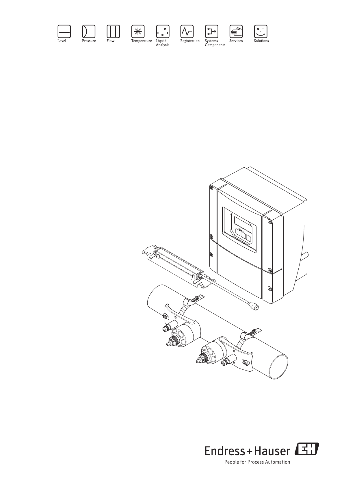
Proline Prosonic Flow 93
HART
Ultrasonic flow measuring system
6
BA00070D/06/EN/13.11
71134382
Valid as of version
V 2.02.XX (Device software)
Page 2

Page 3

Proline Prosonic Flow 93 Table of contents
Table of contents
1 Safety instructions . . . . . . . . . . . . . . . . 5
1.1 Designated use . . . . . . . . . . . . . . . . . . . . . . . . . . . . 5
1.2 Installation, commissioning and operation . . . . . . . . 5
1.3 Operational safety . . . . . . . . . . . . . . . . . . . . . . . . . . 5
1.4 Return . . . . . . . . . . . . . . . . . . . . . . . . . . . . . . . . . . . 6
1.5 Notes on safety conventions and icons . . . . . . . . . . . 6
2 Identification . . . . . . . . . . . . . . . . . . . . 7
2.1 Device designation . . . . . . . . . . . . . . . . . . . . . . . . . 7
2.1.1 Nameplate of the transmitter . . . . . . . . . . . . 7
2.1.2 Nameplate of the sensor . . . . . . . . . . . . . . . 8
2.1.3 Nameplate for the connections . . . . . . . . . . 9
2.2 Certificates and approvals . . . . . . . . . . . . . . . . . . . 10
2.3 Registered trademarks . . . . . . . . . . . . . . . . . . . . . . 10
3 Installation . . . . . . . . . . . . . . . . . . . . . 11
3.1 Incoming acceptance, transport and storage . . . . . . 11
3.1.1 Incoming acceptance . . . . . . . . . . . . . . . . . 11
3.1.2 Transport . . . . . . . . . . . . . . . . . . . . . . . . . 11
3.1.3 Storage . . . . . . . . . . . . . . . . . . . . . . . . . . . 11
3.2 Installation conditions . . . . . . . . . . . . . . . . . . . . . . 11
3.2.1 Dimensions . . . . . . . . . . . . . . . . . . . . . . . . 11
3.2.2 Mounting location . . . . . . . . . . . . . . . . . . . 11
3.2.3 Orientation . . . . . . . . . . . . . . . . . . . . . . . . 12
3.2.4 Inlet and outlet run . . . . . . . . . . . . . . . . . . 12
3.2.5 Sensor selection and arrangement . . . . . . . 13
3.3 Two-channel operation . . . . . . . . . . . . . . . . . . . . . 14
3.3.1 Two-channel measurement . . . . . . . . . . . . 14
3.3.2 Two-path measurement . . . . . . . . . . . . . . . 15
3.4 Preparatory steps prior to installation . . . . . . . . . . . 16
3.5 Determining the necessary installation distances . . 16
3.5.1 Installation distances for Prosonic Flow
P or W clamp-on . . . . . . . . . . . . . . . . . . . 16
3.5.2 Installation distances for Prosonic Flow
W Insertion . . . . . . . . . . . . . . . . . . . . . . . . 16
3.6 Determining values for installation distances . . . . . 17
3.6.1 Determining installation distances
via local operation . . . . . . . . . . . . . . . . . . . 17
3.6.2 Determining installation distances
via FieldCare . . . . . . . . . . . . . . . . . . . . . . . 22
3.6.3 Determining installation distances
via Applicator . . . . . . . . . . . . . . . . . . . . . . 28
3.7 Mechanical preparation . . . . . . . . . . . . . . . . . . . . . 30
3.7.1 Mounting the sensor holder with
U-shaped screws . . . . . . . . . . . . . . . . . . . . 30
3.7.2 Mounting the sensor holder
with strapping bands . . . . . . . . . . . . . . . . . 31
3.7.3 Premounting the strapping bands
(medium nominal diameters) . . . . . . . . . . . 32
3.7.4 Premounting the strapping bands
(large nominal diameters) . . . . . . . . . . . . . 33
3.7.5 Mounting the welded bolts . . . . . . . . . . . . 34
3.8 Installing Prosonic Flow W and P
(DN 15 to 65 / ½ to 2½") . . . . . . . . . . . . . . . . . . . 35
3.8.1 Mounting the sensor . . . . . . . . . . . . . . . . . 35
3.9 Installing Prosonic Flow P DN 50 to 4000
(2 to 160") (Clamp-on) . . . . . . . . . . . . . . . . . . . . . 37
3.9.1 Installation for measurement
via one traverse . . . . . . . . . . . . . . . . . . . . . 37
3.9.2 Installation for measurement
via two traverses . . . . . . . . . . . . . . . . . . . . 39
3.10 Installing Prosonic Flow W (Clamp-on) . . . . . . . . . 41
3.10.1 Installation for measurement
via one traverse . . . . . . . . . . . . . . . . . . . . . 41
3.10.2 Installation for measurement
via two traverses . . . . . . . . . . . . . . . . . . . . 43
3.11 Installing Prosonic Flow W (Insertion version) . . . . 45
3.11.1 Installation for measurement
as single-path insertion version . . . . . . . . . . 46
3.11.2 Installation for measurement
as dual-path insertion version . . . . . . . . . . . 49
3.12 Installing sensor DDU18 . . . . . . . . . . . . . . . . . . . . 53
3.13 Installing sensor DDU19 . . . . . . . . . . . . . . . . . . . . 54
3.13.1 Version 1 . . . . . . . . . . . . . . . . . . . . . . . . . . 54
3.13.2 Version 2 . . . . . . . . . . . . . . . . . . . . . . . . . . 54
3.14 Installing the wall-mount transmitter housing . . . . . 55
3.14.1 Direct wall mounting . . . . . . . . . . . . . . . . . 55
3.14.2 Panel mounting . . . . . . . . . . . . . . . . . . . . . 56
3.14.3 Pipe mounting . . . . . . . . . . . . . . . . . . . . . . 56
3.15 Post-installation check . . . . . . . . . . . . . . . . . . . . . . 57
4 Wiring . . . . . . . . . . . . . . . . . . . . . . . . . 58
4.1 Sensor/transmitter connecting cable . . . . . . . . . . . 58
4.1.1 Connecting and grounding Prosonic Flow
W and P (DN 50 to 4000 / 2 to 160")
Two Single coaxial cables . . . . . . . . . . . . . . 58
4.1.2 Connecting and Grounding Prosonic Flow
W and Prosonic Flow P DN 15 to 65
(½ to 2½") Multicore cable . . . . . . . . . . . . 60
4.1.3 Cable specification for connecting cable . . . 61
4.2 Connecting the measuring unit . . . . . . . . . . . . . . . 61
4.2.1 Connecting the transmitter . . . . . . . . . . . . 61
4.2.2 Terminal assignment . . . . . . . . . . . . . . . . . 62
4.2.3 HART connection . . . . . . . . . . . . . . . . . . . 63
4.3 Potential equalization . . . . . . . . . . . . . . . . . . . . . . . 64
4.4 Degree of protection . . . . . . . . . . . . . . . . . . . . . . . 64
4.5 Post-connection check . . . . . . . . . . . . . . . . . . . . . . 65
5 Operation . . . . . . . . . . . . . . . . . . . . . . 66
5.1 Quick operation guide . . . . . . . . . . . . . . . . . . . . . . 66
5.2 Display and operating elements . . . . . . . . . . . . . . . 66
5.3 Brief guide to the function matrix . . . . . . . . . . . . . . 69
5.3.1 General notes . . . . . . . . . . . . . . . . . . . . . . 70
5.3.2 Enabling the programming mode . . . . . . . . 70
5.3.3 Disabling the programming mode . . . . . . . . 70
5.4 Error messages . . . . . . . . . . . . . . . . . . . . . . . . . . . . 71
5.4.1 Type of error . . . . . . . . . . . . . . . . . . . . . . . 71
5.4.2 Error message types . . . . . . . . . . . . . . . . . . 71
5.4.3 Confirming error messages . . . . . . . . . . . . . 72
Endress+Hauser 3
Page 4

Proline Prosonic Flow 93 Table of contents
5.5 Communication (HART) . . . . . . . . . . . . . . . . . . . . 72
5.5.1 Operating options . . . . . . . . . . . . . . . . . . . 73
5.5.2 Current device description files . . . . . . . . . 74
5.5.3 Device variables and process variables . . . . 74
5.5.4 Universal/common practice
HART commands . . . . . . . . . . . . . . . . . . . 75
5.5.5 Device status/error messages . . . . . . . . . . . 80
6 Commissioning . . . . . . . . . . . . . . . . . . 83
6.1 Function check . . . . . . . . . . . . . . . . . . . . . . . . . . . 83
6.2 Commissioning via onsite display . . . . . . . . . . . . . . 84
6.2.1 Quick Setup "Sensor Installation" . . . . . . . . 84
6.2.2 Quick Setup "Commissioning" . . . . . . . . . . 85
6.2.3 Quick Setup "Pulsating Flow" . . . . . . . . . . . 88
6.3 Application-specific commissioning . . . . . . . . . . . . 91
6.3.1 Zero point adjustment . . . . . . . . . . . . . . . . 91
6.3.2 Advanced diagnostic functions . . . . . . . . . 93
6.3.3 Data storage with "T-DAT SAVE/LOAD" . . 95
6.4 Hardware settings . . . . . . . . . . . . . . . . . . . . . . . . . 96
6.4.1 Switching HART write protection on/off . . 96
6.4.2 Current output: active/passive . . . . . . . . . . 97
6.4.3 Relay contacts: NC contact/NO contact . . 98
6.5 Data storage device (HistoROM, F-CHIP) . . . . . . . . 99
6.5.1 HistoROM/T-DAT (transmitter-DAT) . . . . 99
6.5.2 F-CHIP (function chip) . . . . . . . . . . . . . . . 99
10.1.11 Human interface . . . . . . . . . . . . . . . . . . 129
10.1.12 Certificates and approvals . . . . . . . . . . . . 130
10.1.13 Accessories . . . . . . . . . . . . . . . . . . . . . . 130
10.1.14 Ordering information . . . . . . . . . . . . . . . 130
10.1.15 Documentation . . . . . . . . . . . . . . . . . . . 130
Index . . . . . . . . . . . . . . . . . . . . . . . . . . . . . 131
7 Maintenance . . . . . . . . . . . . . . . . . . . 100
8 Accessories . . . . . . . . . . . . . . . . . . . . 101
9 Troubleshooting . . . . . . . . . . . . . . . . 105
9.1 Troubleshooting instructions . . . . . . . . . . . . . . . . 105
9.2 System error messages . . . . . . . . . . . . . . . . . . . . . 106
9.3 Process error messages . . . . . . . . . . . . . . . . . . . . . 110
9.4 Process errors without messages . . . . . . . . . . . . . 111
9.5 Response of outputs to errors . . . . . . . . . . . . . . . . 112
9.6 Spare parts . . . . . . . . . . . . . . . . . . . . . . . . . . . . . 113
9.7 Installing and removing electronics boards . . . . . . 114
9.8 Installing and removing the W sensors . . . . . . . . . 116
9.9 Replacing the device fuse . . . . . . . . . . . . . . . . . . . 117
9.10 Return . . . . . . . . . . . . . . . . . . . . . . . . . . . . . . . . . 117
9.11 Disposal . . . . . . . . . . . . . . . . . . . . . . . . . . . . . . . 117
9.12 Software history . . . . . . . . . . . . . . . . . . . . . . . . . 118
10 Technical data . . . . . . . . . . . . . . . . . . 119
10.1 Quick technical data guide . . . . . . . . . . . . . . . . . . 119
10.1.1 Application . . . . . . . . . . . . . . . . . . . . . . . 119
10.1.2 Function and system design . . . . . . . . . . . 119
10.1.3 Input . . . . . . . . . . . . . . . . . . . . . . . . . . . . 119
10.1.4 Output . . . . . . . . . . . . . . . . . . . . . . . . . . 120
10.1.5 Power supply . . . . . . . . . . . . . . . . . . . . . . 122
10.1.6 Performance characteristics . . . . . . . . . . . 123
10.1.7 Operating conditions: installation . . . . . . . 125
10.1.8 Operating conditions: environment . . . . . 125
10.1.9 Operating conditions: process . . . . . . . . . 126
10.1.10 Mechanical construction . . . . . . . . . . . . . 127
4 Endress+Hauser
Page 5

Proline Prosonic Flow 93 Safety instructions
1 Safety instructions
1.1 Designated use
The measuring device described in these Operating Instructions is to be used only for measuring the
flow rate of liquids in closed pipes.
Examples:
• Acids, alkalis, paints, oils
• Liquid gas
• Ultrapure water with low conductivity, water, wastewater
As well as measuring the volume flow, the sound velocity of the fluid is also always measured.
Different fluids can be distinguished or the fluid quality can be monitored.
Resulting from incorrect use or from use other than that designated the operational safety of the
measuring devices can be suspended. The manufacturer accepts no liability for damages being
produced from this.
1.2 Installation, commissioning and operation
Note the following points:
• Installation, connection to the electricity supply, commissioning and maintenance of the device
must be carried out by trained, qualified specialists authorized to perform such work by the
facility's owner-operator.
The specialist must have read and understood these Operating Instructions and must follow the
instructions they contain.
• The device must be operated by persons authorized and trained by the facility's owner-operator.
Strict compliance with the instructions in these Operating Instructions is mandatory.
• Endress+Hauser is willing to assist in clarifying the chemical resistance properties of parts wetted
by special fluids, including fluids used for cleaning.
However, small changes in temperature, concentration or the degree of contamination in the
process can result in changes to the corrosion resistance properties. Therefore, Endress+Hauser
cannot guarantee or accept liability for the corrosion resistance properties of wetted materials in
a specific application.
The user is responsible for choosing suitable wetted materials in the process.
• If carrying out welding work on the piping, the welding unit may not be grounded by means of
the measuring device.
• The installer must ensure that the measuring system is correctly wired in accordance with the
wiring diagrams. The transmitter must be grounded, except in cases where special protective
measures have been taken (e.g. galvanically isolated power supply SELV or PELV).
• Invariably, local regulations governing the opening and repair of electrical devices apply.
1.3 Operational safety
Note the following points:
• Measuring systems for use in hazardous environments are accompanied by separate "Ex
documentation", which is an integral part of these Operating Instructions. Strict compliance with
the installation instructions and ratings as stated in this supplementary documentation is
mandatory. The symbol on the front of this supplementary Ex documentation indicates the
approval and inspection authority (e.g. 0 Europe, 2 USA, 1 Canada).
• The measuring system complies with the general safety requirements in accordance with
EN 61010-1, the EMC requirements of IEC/EN 61326, and NAMUR Recommendation NE 21
and NE 43.
• The manufacturer reserves the right to modify technical data without prior notice. Your
Endress+Hauser distributor will supply you with current information and updates to this
Operating Instructions.
Endress+Hauser 5
Page 6

Safety instructions Proline Prosonic Flow 93
1.4 Return
The following procedures must be carried out before a flowmeter requiring repair or calibration, for
example, is returned to Endress+Hauser:
• Always enclose a duly completed "Declaration of Contamination" form. Only then can
Endress+Hauser transport, examine and repair a returned device.
Note!
!
You will find a preprinted "Declaration of Contamination" form at the back of this manual.
• Enclose special handling instructions if necessary, for example a safety data sheet as per
Regulation (EC) No 1907/2006 REACH.
• Remove all residues. Pay special attention to the grooves for seals and crevices which could
contain residues. This is particularly important if the substance is hazardous to health, e.g.
flammable, toxic, caustic, carcinogenic, etc.
#
Warning!
• Do not return a measuring device if you are not absolutely certain that all traces of hazardous
substances have been removed, e.g. substances which have penetrated crevices or diffused
through plastic.
• Costs incurred for waste disposal or injury (burns, etc.) due to inadequate cleaning will be charged
to the owner-operator.
#
"
!
1.5 Notes on safety conventions and icons
The devices are designed and tested to meet state-of-the-art safety requirements, and have left the
factory in a condition in which they are safe to operate. The devices comply with the applicable
standards and regulations in accordance with EN 61010 -1 "Protection Measures for Electrical
Equipment for Measurement, Control, Regulation and Laboratory Procedures". The devices can,
however, be a source of danger if used incorrectly or for other than the designated use.
For this reason, always pay particular attention to the safety instructions indicated in these
Operating Instructions by the following icons:
Warning!
"Warning" indicates an action or procedure which, if not performed correctly, can result in personal
injury or a safety hazard. Comply strictly with the instructions and proceed with care.
Caution!
"Caution" indicates an action or procedure which, if not performed correctly, can result in incorrect
operation or destruction of the device. Comply strictly with the instructions.
Note!
"Note" indicates an action or procedure which, if not performed correctly, can have an indirect
effect on operation or trigger an unexpected response on the part of the device.
6 Endress+Hauser
Page 7
Proline Prosonic Flow 93 Identification
PROSONIC FLOW 93
-20°C (-4°F) <Tamb<+60°C (+140°F)
IP67 / NEMA/Type 4XOrder Code:
Ser.No.:
TAG No.:
93PA1-XXXXXXXXXXXX
12345678901
ABCDEFGHJKLMNPQRST
16-62VDC/20-55VAC
50-60Hz
I-OUT (HART), f-OUT
15VA/W
i
Pat. US 5,479,007
Pat. UK EP 618 680
STATUS-OUT, STATUS-IN
2
3
4
5
76
1
2 Identification
2.1 Device designation
The "Prosonic Flow 93" flowmeter system consists of the following components:
• Prosonic Flow 93 transmitter
•Sensor:
– Prosonic Flow P Clamp-on version (DN 15 to 65 / ½ to 2½")
– Prosonic Flow P Clamp-on version (DN 50 to 4000 / 2 to 160")
– Prosonic Flow W Clamp-on version (DN 15 to 65 / ½ to 2½")
– Prosonic Flow W Clamp-on version (DN 50 to 4000 / 2 to 160")
– Prosonic Flow W Insertion version
The transmitter and sensor are mounted separately from one another and connected by a
connecting cable.
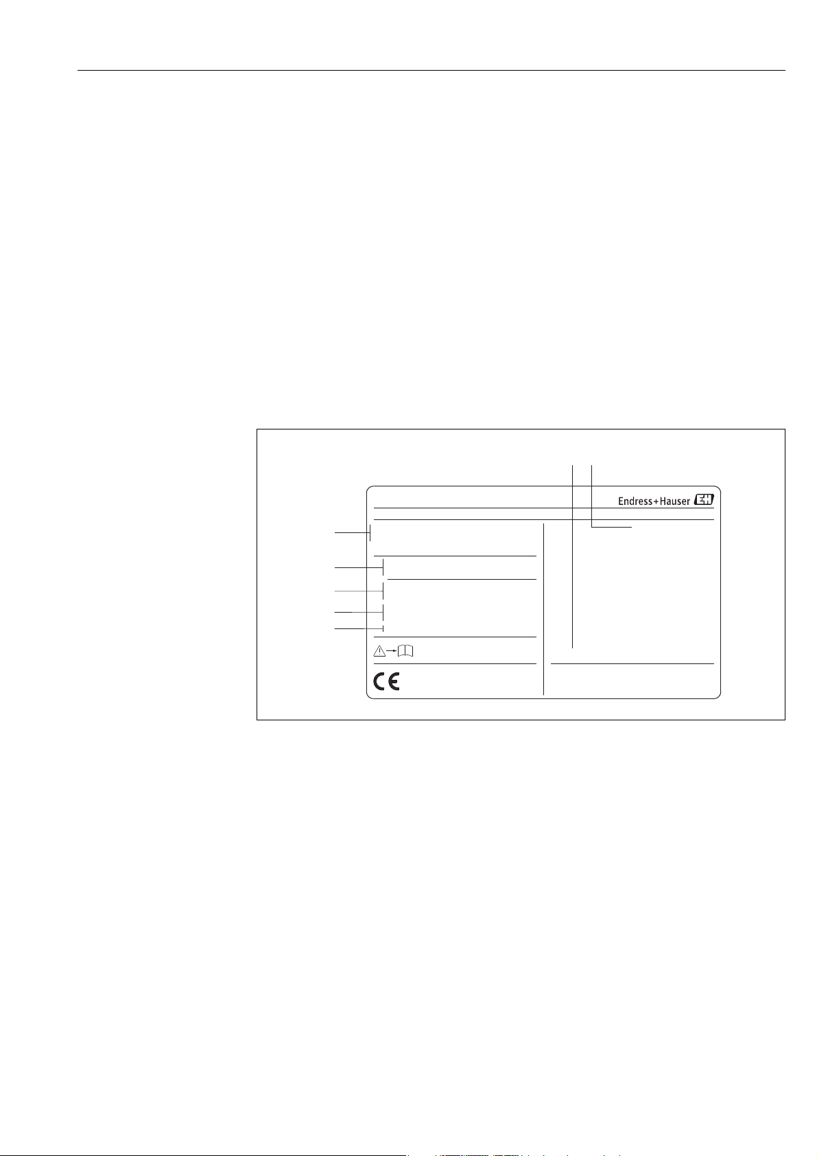
2.1.1 Nameplate of the transmitter
A0001157
Fig. 1: Nameplate specifications for the "Prosonic Flow 93" transmitter (example)
1 Order code/serial number: See the specifications on the order confirmation for the meanings of the individual
letters and digits
2 Power supply/frequency: 16 to 62 V DC / 20 to 55 V AC / 50 to 60 Hz
Power consumption: 15 VA / W
3 Reserved for additional information
4 Available inputs and outputs:
I-OUT (HART): with current output (HART)
f-OUT: with pulse/frequency output
RELAY: with relay output
STAT-IN: with status input (auxiliary input)
5Reserved for information on special products
6 Permitted ambient temperature range
7 Degree of protection
Endress+Hauser 7
Page 8
Identification Proline Prosonic Flow 93
N12895
4153 Reinach, Switzerland
II2G EEx ib IIC T6-T1
DMT 01 ATEX E 064 X
IECEx BVS 06.0... X
FEK0924
ENDRESS+HAUSER
TYPE 6P
NEMA
IP68
Tamb/Tumg:-40°C..+60°C
control dwg. of transmitter
For Installation refer to
CL.II, GP. EFG, CL.III
Dust-Ignitionproof for
CL.II, GP.EFG, CL.III
Intrinsically safe for CL.I, GP.ABCD
APPROVED
FM
0044
Warning: To maintain
Type/NEMA6p or IP68
protection the connector
must be fully engaged.
II2D Ex ibD 21 T6-T1
CH 1
XXXXX-XXXXXXXXXXXX
P-CL-1F-L-B
12345678901 RY
-40°C (-40°F) ... +80°C (+175°F)
Order Code:
DN100 - DN4000
Type:
Ser.No.:
i
2007
06/../....
XA059D/
OPEN CLOSE
PROSONIC FLOW P
4153 Reinach
Switzerland
8
7
1
2
3
4
5
6
9
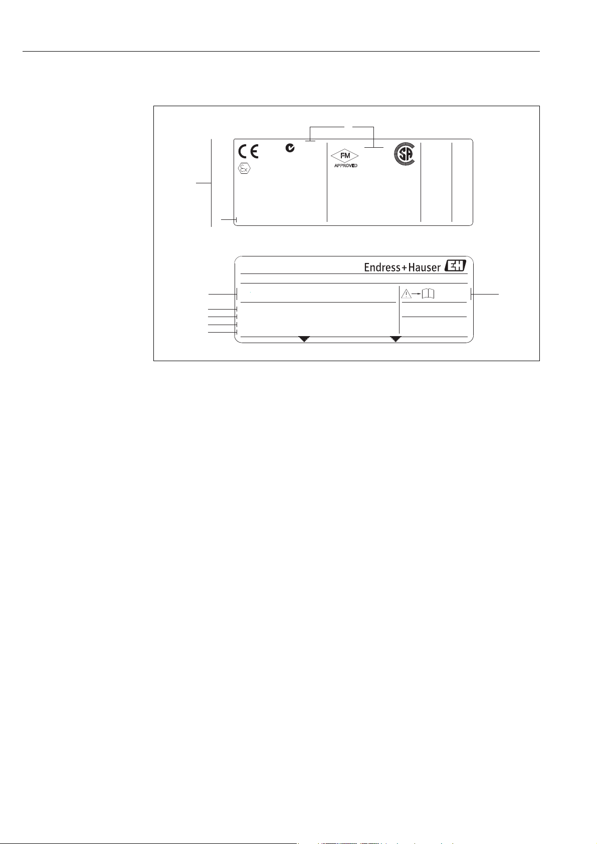
2.1.2 Nameplate of the sensor
A0001158
Fig. 2: Nameplate specifications for the "Prosonic Flow P" sensor (example)
1 Order code/serial number: See the specifications on the order confirmation for the meanings of the individual
letters and digits.
2Sensor type
3 Range of nominal diameter: DN 100 to 4000 (4 to 160")
4 Max. fluid temperature range: –40 to +80 °C (–40 to +175 °F)
5Reserved for information on special products
6 Degree of protection
7 Permitted ambient temperature range
8 Data on explosion protection
Refer to the specific additional Ex documentation for detailed information.
Please do not hesitate to contact your Endress+Hauser sales office if you have any questions.
8 Endress+Hauser
Page 9
Proline Prosonic Flow 93 Identification
Communication:
Drivers:
Device SW:
ID xxxx (HEX)
XX.XX.XX (WEA)
XXXXXXXXXX
Date: DD.MMM.YYYY
Ex-works / ab-Werk/réglages usine
26(+) / 27(-)
NC:
Versorgung /
Tension d'alimentation
Observer manuel d'instruction
See operating manual
Betriebsanleitung beachten
Active: 0/4...20mA, RL max.=700 Ohm
Passive: 4...20mA, max. 30VDC
Passive: 30VDC, 250mA
Active: 24VDC/25mA (max. 250mA/20ms)
Passive: 30VDC, 250mA
(HART:RL.min.=250 OHM)
fmax = 1kHz
3...30VDC, Ri = 5kOhm
f-OUT
I-
OUT (HART)
12345678912Ser.No.:
Supply /
24(+) / 25(-)
22(+) / 23(-)
20(+) / 21(-)
N/LPE
A:
NO:
P:
L1/L+
12
319475-00XX
A
P
active
passive
normally open contact
normallyclosed contact
X
STATUS-OUT
STATUS-IN
X
Update 1 Update 2
2
3
1
4
5
6
7
8
9
10
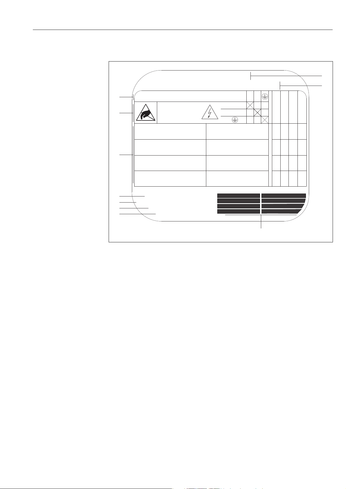
2.1.3 Nameplate for the connections
A0000963
Fig. 3: Nameplate specifications for Proline transmitter (example)
1 Serial number
2 Possible configuration of the current input
3 Possible configuration of the relay contacts
4 Terminal assignment, cable for power supply: 85 to 260 V AC, 20 to 55 V AC, 16 to 62 V DC
Terminal No. 1: L1 for AC, L+ for DC
Terminal No. 2: N for AC, L- for DC
5 Signals present at the inputs and outputs, possible configurations and terminal assignment (20 to 27), see also
"Electrical values of the inputs/outputs"
6 Version of device software currently installed
7 Installed communication mode e.g.: HART, PROFIBUS PA, etc.
8 Information on current communication software (Device Revision and Device Description),
e.g.: Dev. 01 / DD 01 for HART
9 Date of installation
10 Current updates to the information listed in Points 6 to 9
Endress+Hauser 9
Page 10

Identification Proline Prosonic Flow 93
2.2 Certificates and approvals
The devices are designed in accordance with good engineering practice to meet state-of-the-art
safety requirements, have been tested, and left the factory in a condition in which they are safe to
operate.
The devices comply with the applicable standards and regulations in accordance with EN 61010-1
"Safety requirements for electrical equipment for measurement, control and laboratory use" and
with the EMC requirements of IEC/EN 61326.
The measuring system described in these Operating Instructions thus complies with the statutory
requirements of the EC Directives. Endress+Hauser confirms successful testing of the device by
affixing to it the CE mark.
The measuring system complies with the EMC requirements of the "Australian Communications
and Media Authority (ACMA)".
2.3 Registered trademarks
HART ®
Registered trademark of HART Communication Foundation, Austin, USA
®
HistoROM™, T-DAT™, F-CHIP
Registered or registration-pending trademarks of Endress+Hauser Flowtec AG, Reinach, CH
, FieldCare®, Fieldcheck®, FieldXpert™, Applicator
®
10 Endress+Hauser
Page 11
Proline Prosonic Flow 93 Installation
3 Installation
3.1 Incoming acceptance, transport and storage
3.1.1 Incoming acceptance
On receipt of the goods, check the following points:
• Check the packaging and the contents for damage.
• Check the shipment, make sure nothing is missing and that the scope of supply matches your
order.
3.1.2 Transport
The devices must be transported in the container supplied when transporting them to the measuring
point.
3.1.3 Storage
• Pack the measuring device in such a way as to protect it reliably against impact for storage (and
transportation). The original packaging provides optimum protection.
• The storage temperature corresponds to the ambient temperature range of the transmitter, the
sensors and the corresponding sensor cables ( ä 119).
• The measuring device must be protected against direct sunlight during storage in order to avoid
unacceptably high surface temperatures.
3.2 Installation conditions
3.2.1 Dimensions
The dimensions and lengths of the sensor and transmitter are provided in the separate "Technical
Information" document on the device in question. This can be downloaded as a PDF file from
www.endress.com.
A list of the "Technical Information" documents available is provided on ä 130.
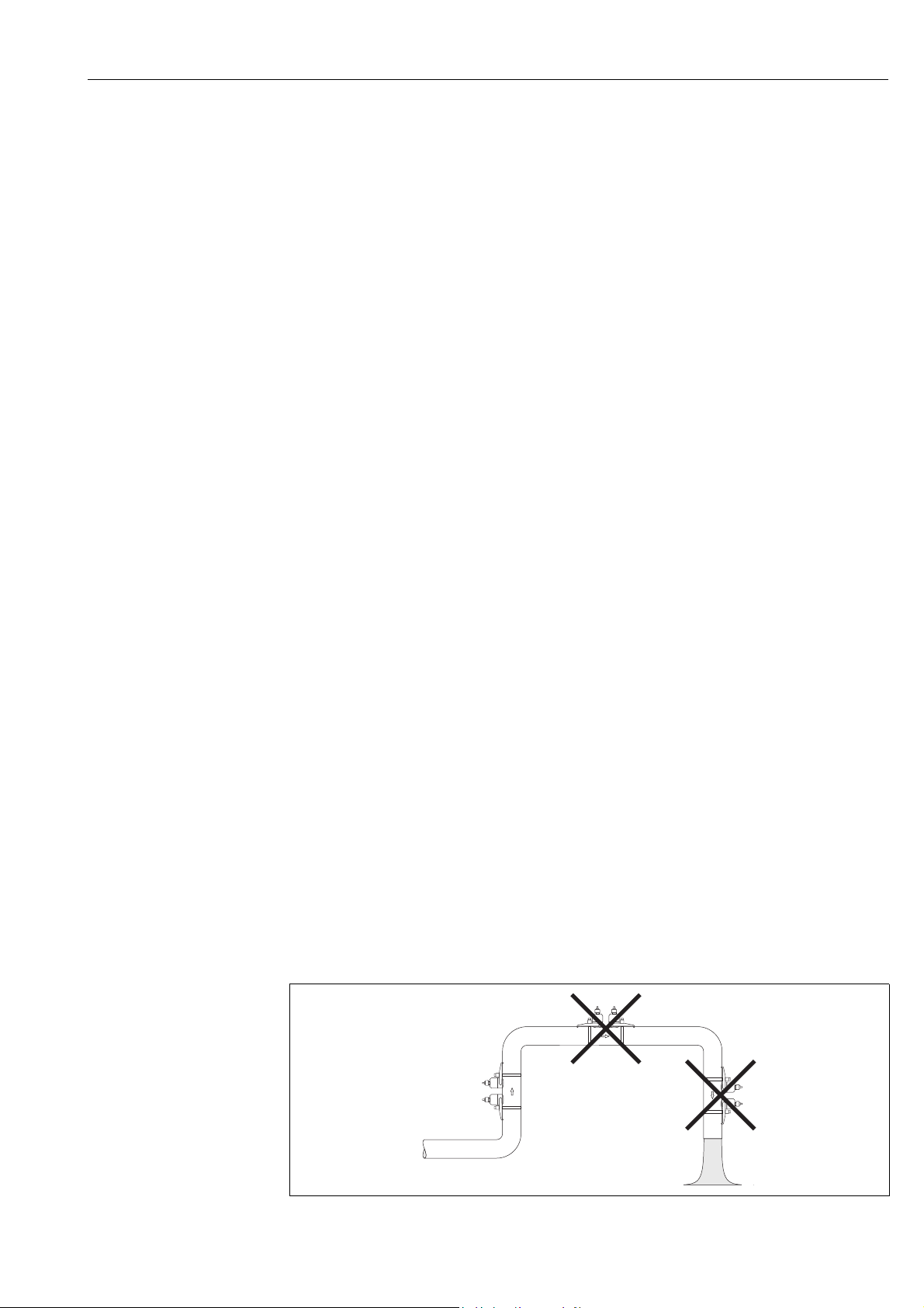
3.2.2 Mounting location
Correct flow measurement is possible only if a pipe is full. Entrained air or gas bubbles forming in
the pipe can result in an increase in measuring errors.
Avoid the following locations in the pipe installation:
• Highest point of a pipeline. Risk of air accumulating.
• Directly upstream of a free pipe outlet in a vertical pipeline.
A0001103
Fig. 4: Mounting location
Endress+Hauser 11
Page 12
Installation Proline Prosonic Flow 93
A
B
CC
15xDN
20xDN
20xDN
15xDN
3xDN
1
2
3
15xDN
10xDN
20xDN
20xDN
20xDN
15xDN
15xDN
10xDN
3xDN
3xDN
1
2
3
AB
11
22
1
2
1
2
1
2
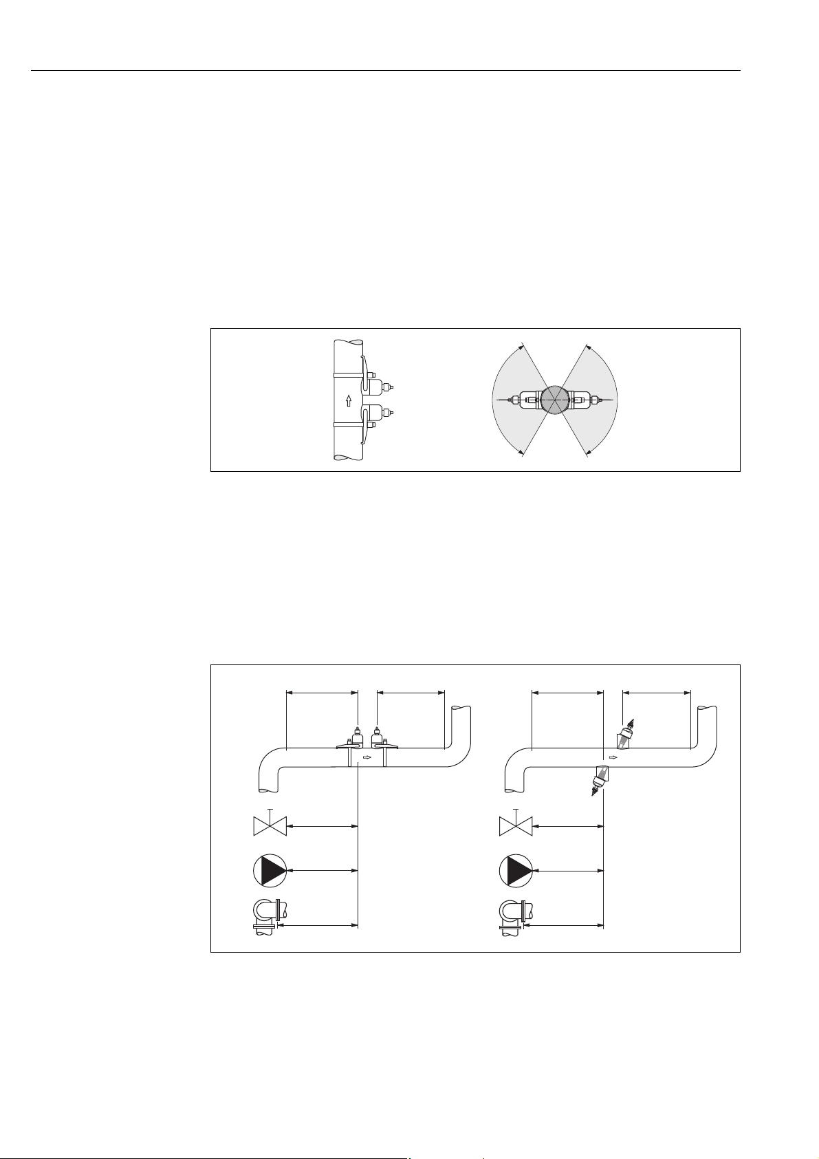
3.2.3 Orientation
Vertical orientation
We recommend the sensor be mounted where there is upward direction of flow. With this
orientation, entrained solids will sink down and gases will rise away from the sensor when the fluid
is stagnant.
Horizontal orientation
We recommend the sensors be mounted within an angle of ±60° to the horizontal (area shaded gray
in the graphic). With this orientation, flow measurement is less affected by any gas or air
accumulation in the upper area of the pipe or by buildup at the bottom of the pipe.
A0001105
Fig. 5: Recommended orientation and recommended installation range
A Vertical: Recommended installation with vertical/upward direction of flow
B Horizontal: Recommended installation range with horizontal orientation
C Recommended installation range max. 120°
3.2.4 Inlet and outlet run
If possible, install the sensor well clear of assemblies such as valves, T-pieces, elbows, etc. If several
flow obstructions are installed, the longest inlet or outlet run must be considered. Compliance with
the following inlet and outlet runs is required in order to ensure measuring accuracy.
Fig. 6: Recommended inlet and outlet runs to comply with measuring accuracy specifications
AClamp-on version
BInsertion version
1
= values for single-path version
2
= values for two-path version
1Valve (2/3 open)
2Pump
3 Two pipe bends in different directions
12 Endress+Hauser
A0013845
Page 13
Proline Prosonic Flow 93 Installation
BA
3.2.5 Sensor selection and arrangement
The sensors can be arranged in two ways:
• Mounting arrangement for measurement via one traverse: the sensors are located on opposite
sides of the pipe.
• Mounting arrangement for measurement via two traverses: the sensors are located on the same
side of the pipe.
A0001108
Fig. 7: Sensor mounting arrangement (top view)
A Mounting arrangement for measurement via one traverse
B Mounting arrangement for measurement via two traverses
The number of traverses required depends on the sensor type, the nominal diameter and the
thickness of the pipe wall. We recommend the following types of mounting:
Sensor Type Nominal Diameter Sensor Frequency Sensor ID Type of Mounting
DN 15 to 65 (½ to 2½") 6 MHz P-CL-6F* 2 traverses
DN 50 to 65 (2 to 2½") 2 MHz
P-CL-6F*
P-CL-2F*
2 (or 1) traverses
5)
DN 80 (3") 2 MHz P-CL-2F* 2 traverses
Prosonic Flow P
DN 100 to 300 (4 to 12") 2 MHz (or 1 MHz)
DN 300 to 600 (12 to 24") 1 MHz (or 2 MHz)
P-CL-2F*
P-CL-1F*
P-CL-1F*
P-CL-2F*
2 traverses
2 traverses
DN 650 to 4000 (26 to 160") 1 MHz P-CL-1F* 1 traverse
DN 15 to 65 (½ to 2½") 6 MHz W-CL-6F* 2 traverses
5)
DN 50 to 65 (2 to 2½") 2 MHz W-CL-2F* 2 (or 1) traverses
DN 80 (3") 2 MHz W-CL-2F* 2 traverses
Prosonic Flow W
DN 100 to 300 (4 to 12") 2 MHz (or 1 MHz)
DN 300 to 600 (12 to 24") 1 MHz (or 2 MHz)
DN 650 to 4000 (26 to 160") 1 MHz (or 0.5 MHz)
1)
The installation of clamp-on sensors is principally recommended in the 2 traverse type installation. This type of
W-CL-2F*
W-CL-1F*
W-CL-1F*
W-CL-2F*
W-CL-1F*
W-CL-05F*
2 traverses
2 traverses
1 traverse
3)
3)
3)
installation allows the easiest and most comfortable type of mounting and means that a system can also be mounted
even if the pipe can only be accessed from one side. However, in certain applications a 1 traverse installation may be
preferred. These include:
• Certain plastic pipes with wall thickness > 4 mm (0.16")
• Pipes made of composite materials such as GRP
• Lined pipes
• Applications with fluids with high acoustic damping
2)
If the pipe nominal diameter is small (DN 65 / 2½" and smaller), the sensor spacing with Prosonic Flow W can be too
small for two traverse installation. In this case, the 1 traverse type of installation must be used.
3)
0.5 MHz sensors are also recommended for applications with composite material pipes such as GRP and may be
recommended for certain lined pipes, pipes with wall thickness > 10 mm (0.4"), or applications with media with high
acoustic damping. In addition, for these applications we principally recommend mounting the W sensors in
a 1 traverse configuration.
4)
Insertion W sensors are mounted in a 1 traverse configuration ä 45.
5)
6 MHz sensors for applications where flow velocity10m/s (32.8Hz/s)
1)
2)
Endress+Hauser 13
Page 14
Installation Proline Prosonic Flow 93
BA
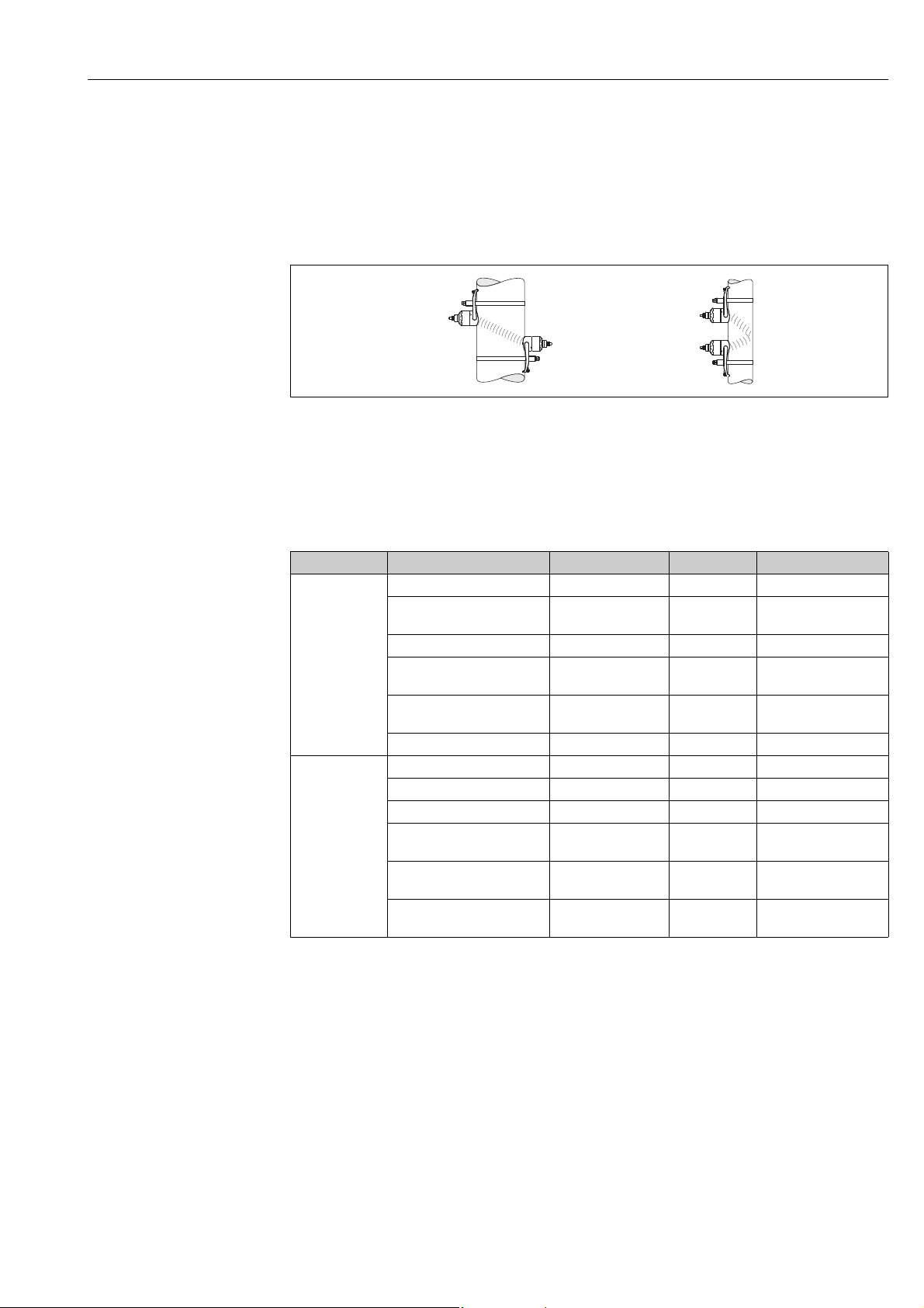
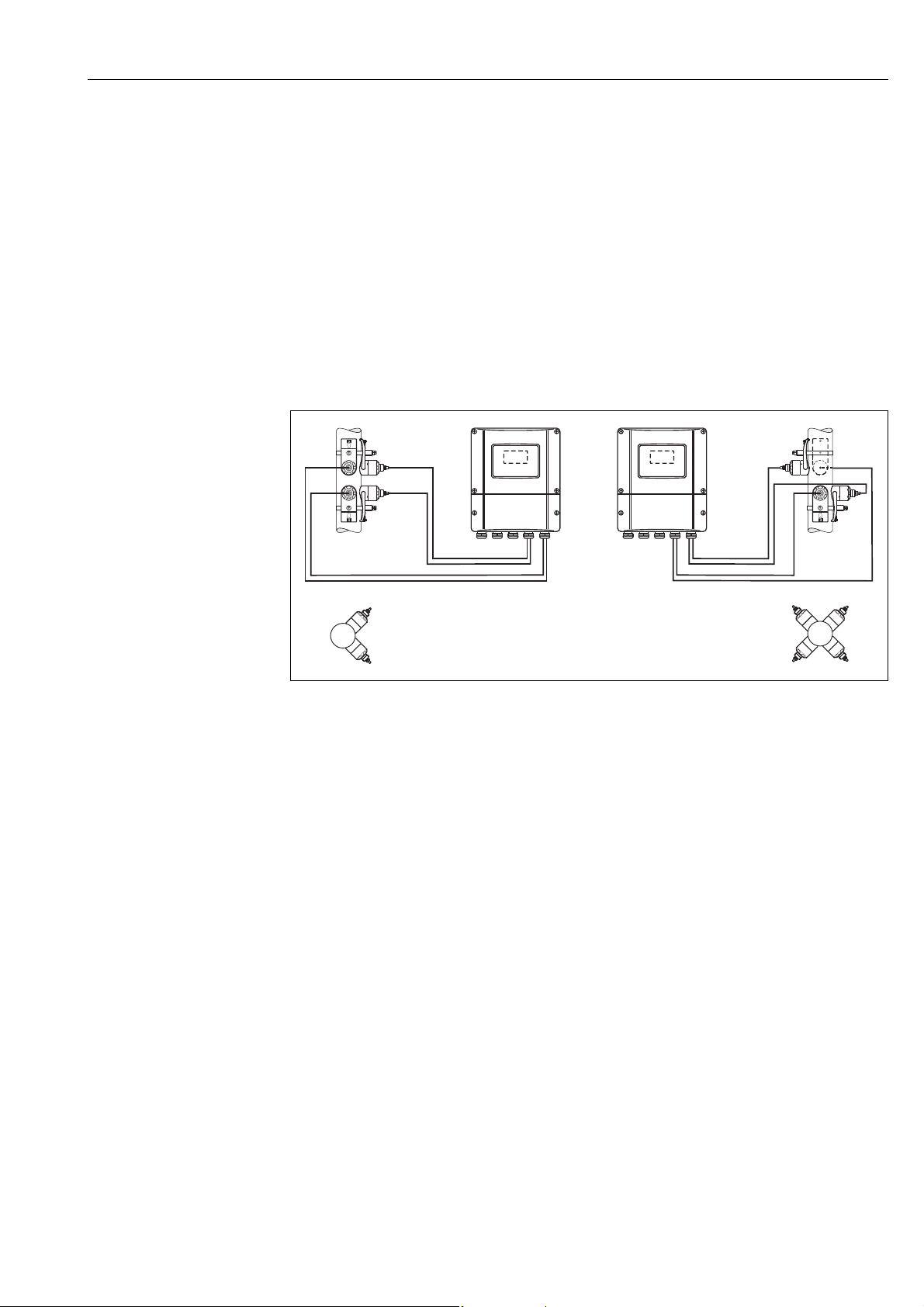
3.3 Two-channel operation
The transmitter is able to operate two independent measuring channels (measuring channel 1 and
measuring channel 2). A pair of sensors is connected per measuring channel. Both measuring
channels operate independently of one another and are supported by the transmitter to an equal
extent.
Two-channel operation can be used for the following measurements:
• Two-channel measurement = flow measurement at two separate measuring points
• Two-path measurement = redundant flow measurement at one measuring point
3.3.1 Two-channel measurement
The flow is measured at two separate measuring points in the case of two-channel measurement.
The measured values of the two measuring channels can be processed and displayed differently.
The following measured values can be output for two-channel measurement:
• Individual measured values per measuring channel (output independently of one another)
• The difference between the two measured values
• The sum of the two measured values
The two measuring channels can be configured individually. This makes it possible to independently
configure and select the display, outputs, sensor type and type of installation.
Fig. 8: Two-channel measurement: example of arranging sensor pairs at two separate measuring points
A Measuring channel 1: mounting the sensor pair for measurement via two traverses
B Measuring channel 2: mounting the sensor pair for measurement via one traverse
A0001159
14 Endress+Hauser
Page 15
Proline Prosonic Flow 93 Installation
BA
3.3.2 Two-path measurement
The flow is measured redundantly at one measuring point in the case of two-path measurement.
The measured values of the two measuring channels can be processed and displayed differently. The
following measured values can be output for two-path measurement:
• Individual measured values per measuring channel (output independently of one another)
• The average of the two measured values.
The "Averaging" function generally provides you with a more stable measured value. The function
is thus suitable for measurements under conditions that are not ideal (e.g. short inlet runs).
The two measuring channels can be configured individually. This makes it possible to independently
configure and select the display, outputs, sensor type and type of installation.
It is generally not necessary to individually configure the two measuring channels in the case of twopath measurement. However, in certain situations individual channel configuration can be used to
balance out application-specific asymmetries.
A0001160
Fig. 9: Two-path measurement: examples of arranging sensor pairs at one measuring point
A Measuring channel 1 and measuring channel 2: mounting the two sensor pairs for one measurement per pair via
two traverses
B Measuring channel 1 and measuring channel 2: mounting the two sensor pairs for one measurement per pair via
one traverse
Endress+Hauser 15
Page 16
Installation Proline Prosonic Flow 93
3.4 Preparatory steps prior to installation
Depending on the conditions specific to the measuring point (e.g. clamp-on, number of traverses,
fluid, etc.), a number of preparatory steps have to be taken before actually installing the sensors:
1. Determination of the values for the necessary installation distances based on the conditions
specific to the measuring point. A number of methods are available for determining the values:
– Local operation of the device
– FieldCare (operating program), connect a notebook to the transmitter
– Applicator (software), online on the Endress+Hauser Internet site
2. Mechanical preparation of the clamp-on retainers for the sensors:
– Premount the strapping bands (DN 50 to 200 / 2 to 8") or (DN 250 to 4000 / 10 to 160")
– Fix the welded bolts
3.5 Determining the necessary installation distances
The installation distances that have to be maintained depend on:
• The type of sensor: P or W (DN 50 to 4000 / 2 to 160"), P or W (DN 15 to 65 / ½ to 2½")
• Type of mounting:
– Clamp-on with strapping band or welded bolt
– Insertion version, installation in the pipe
• Number of traverses or single-path/dual-path version
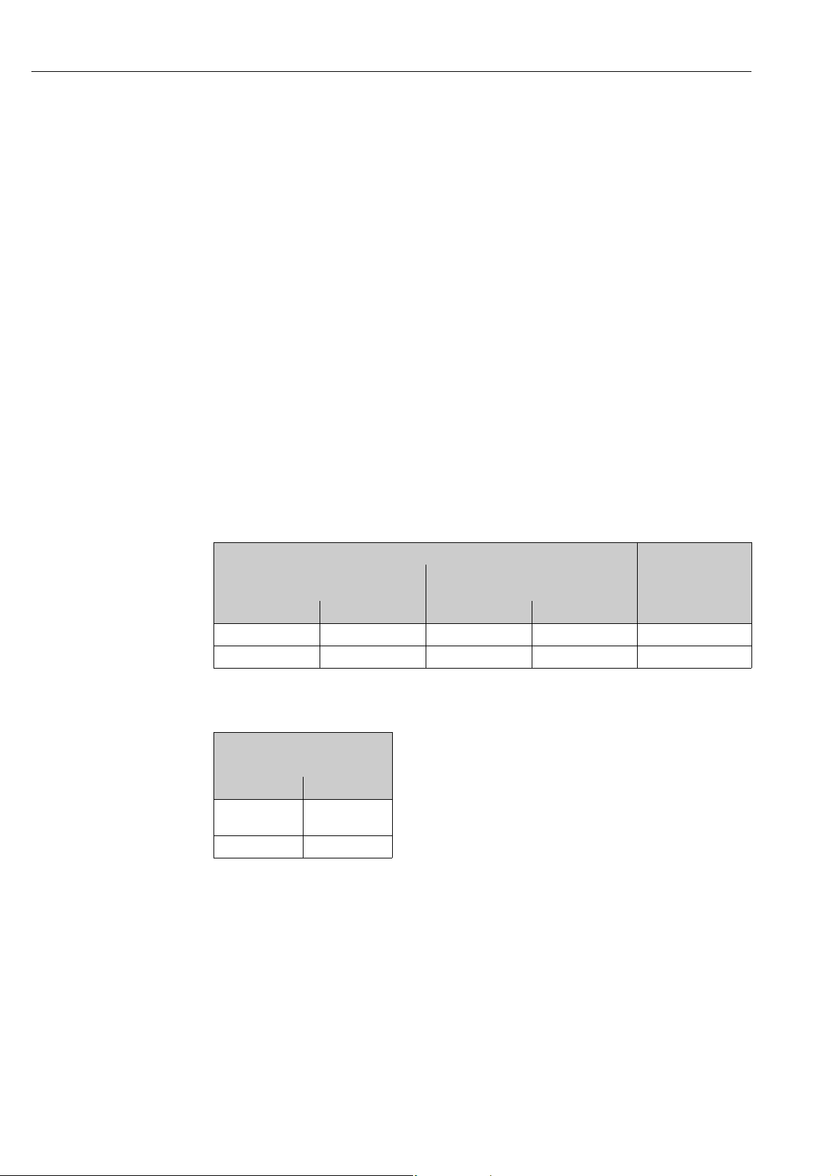
3.5.1 Installation distances for Prosonic Flow P or W clamp-on
DN 50 to 4000 (2 to 160") DN 15 to 65 (½ to 2½")
Clamp-on
Strapping band
1 traverse 2 traverses 1 traverse 2 traverses 2 traverses
SENSOR DISTANCE SENSOR DISTANCE SENSOR DISTANCE SENSOR DISTANCE SENSOR DISTANCE
WIRE LENGTH POSITION SENSOR WIRE LENGTH POSITION SENSOR –
Clamp-on
Welded bolts
Clamp-on
Strapping band
3.5.2 Installation distances for Prosonic Flow W Insertion
DN 200 to 4000 (8 to 160")
Insertion version
Single-path Dual-path
SENSOR
DISTANCE
PATH LENGTH ARC LENGTH
SENSOR
DISTANCE
16 Endress+Hauser
Page 17
Proline Prosonic Flow 93 Installation
a
b
c
c
90 (3.54)
35 (1.38)
192 (7.56)
81.5(3.2)
mm (inch)
3.6 Determining values for installation distances
3.6.1 Determining installation distances via local operation
Perform the following steps to determine the installation distances:
1. Mount the wall-mount housing.
2. Connect the power supply.
3. Switch on the measuring device.
4. Run the "Sensor Installation" Quick Setup menu.
Installing the wall-mount transmitter housing
There are various ways of installing the wall-mount housing:
• Direct wall mounting
• Panel mounting (with separate mounting kit, accessories) ä 101
• Pipe mounting (with separate mounting kit, accessories) ä 101
Caution!
"
• Make sure that the permitted operating temperature range (-20 to +60 °C / –4 to +140 °F) is not
exceeded at the mounting location. Install the device in a shady location. Avoid direct sunlight.
• Always install the wall-mount housing in such a way that the cable entries are pointing down.
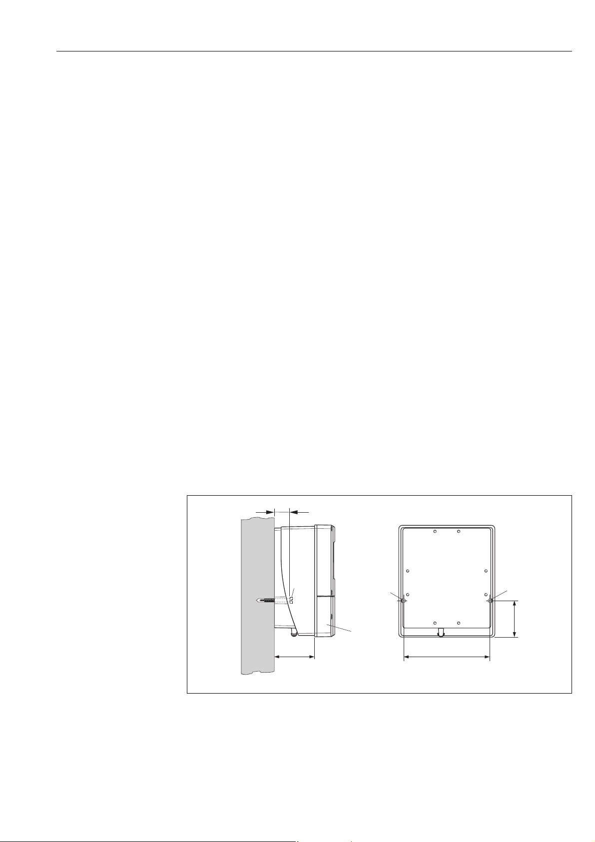
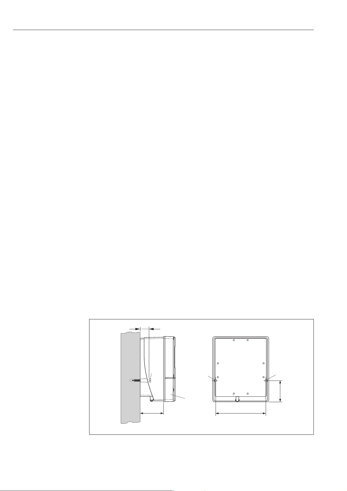
Direct wall mounting
1. Drill the holes ä 17.
2. Remove the cover of the connection compartment (a).
3. Push the two securing screws (b) through the appropriate bores (c) in the housing.
– Securing screws (M6): max. Ø 6.5 mm (0.26")
– Screw head: max. Ø 10.5 mm (0.41")
4. Secure the transmitter housing to the wall as indicated.
5. Screw the cover of the connection compartment (a) firmly onto the housing.
Fig. 10: Direct wall mounting
Endress+Hauser 17
A0001130
Page 18
Installation Proline Prosonic Flow 93
245(9.65)
~110 (~4.33)
210 (8.27)
+0.5 (+0.019)
–0.5(–0.019)
+0.5 (+0.019)
–0.5(–0.019)
mm (inch)
Ø 20…70
(Ø 0.79…2.75)
~~6.1)155 (
mm (inch)
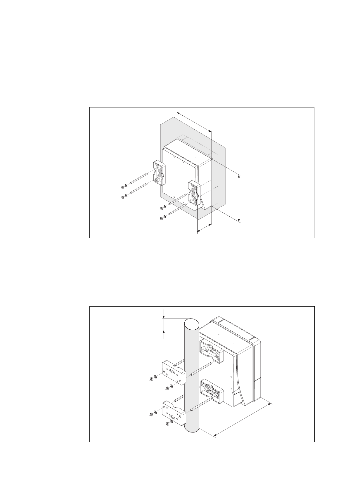
Panel mounting
1. Prepare the opening in the panel ä 18.
2. Slide the housing into the panel cutout from the front.
3. Screw the retainers onto the wall-mount housing.
4. Screw the threaded rods into the retainers and tighten until the housing is solidly seated on the
panel wall. Tighten the counter nuts. No further support is necessary.
Fig. 11: Panel mounting (wall-mount housing)
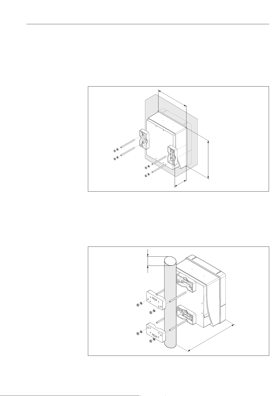
Pipe mounting
The assembly should be performed by following the instructions on ä 18.
Caution!
"
If a warm pipe is used for installation, make sure that the housing temperature does not exceed the
max. permitted value of +60 °C (+140 °F).
A0001131
Fig. 12: Pipe mounting (wall-mount housing)
18 Endress+Hauser
A0001132
Page 19
Proline Prosonic Flow 93 Installation
1
2
a1a
a
+
22
–
23
+
20
–
21
+
24
–
25
+
26
–
27
L1 (L+) N (L-)
A
A
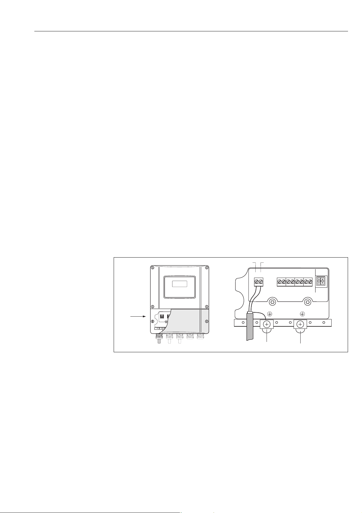
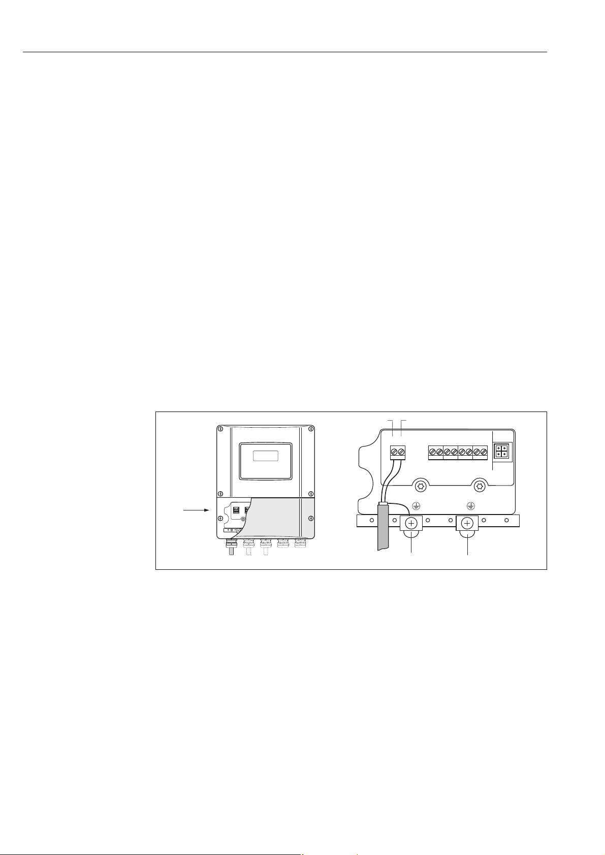
Connecting the power supply
#
!
#
Warning!
When connecting Ex-certified devices, please refer to the notes and diagrams in the Ex-specific
supplement to these Operating Instructions. Please do not hesitate to contact your Endress+Hauser
sales office if you have any questions.
Note!
The measuring device does not have an internal power switch. For this reason, assign the measuring
device a switch or power-circuit breaker which can be used to disconnect the power supply line
from the power grid.
Connecting the power supply
Warning!
• Risk of electric shock. Switch off the power supply before opening the device. Do not install or
wire the device while it is connected to the power supply. Failure to comply with this precaution
can result in irreparable damage to the electronics.
• Risk of electric shock. Connect the protective ground to the ground terminal on the housing
before the power supply is applied (not required for galvanically isolated power supply).
• Compare the specifications on the nameplate with the local supply voltage and frequency. The
national regulations governing the installation of electrical equipment also apply.
1. Remove the cover of the connection compartment from the transmitter housing.
2. Route the power supply cable through the cable entries.
3. Wire the power supply cable.
4. Tighten the cable gland.
5. Screw the connection compartment cover back onto the transmitter housing.
Fig. 13: Connecting the power supply; cable cross-section: max. 2.5 mm (14 AWG)
a Cable for power supply: 85 to 260 V AC, 20 to 55 V AC, 16 to 62 V DC
Terminal No. 1: L1 for AC, L+ for DC
Terminal No. 2: N for AC, L- for DC
a1 Ground terminal for protective ground
Switching on the measuring device
1. Perform the post-connection check as specified in the checklist ä 65.
2. Switch on the supply voltage for the device. The device performs internal test functions.
!
Various messages appear on the display.
3. Normal measuring mode commences. Various measured value and/or status variables appear
on the display (HOME position).
Note!
If startup fails, an appropriate error message is displayed, depending on the cause ä 105.
Endress+Hauser 19
A0011363
Page 20
Installation Proline Prosonic Flow 93
Running the "Sensor Installation" Quick Setup menu
!
Note!
• If you are not familiar with the operation of the device ä 66.
• The following section only describes the steps necessary for clamp-on and insertion type of
mounting within the "Sensor Installation" Quick Setup.
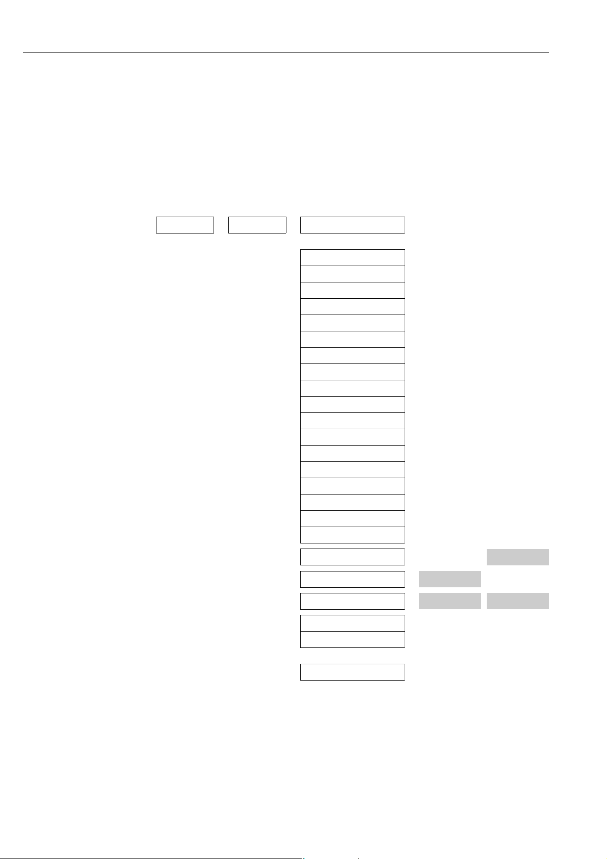
Running the Quick Setup for clamp-on type of mounting
1. Enter or select installation-specific values or the values specified here.
2. Read off the installation distances necessary for mounting.
Home position Quick Setup Setup sensor
Language
CH1 Channel
Clamp-on Measurement
Sensor type
1 or 2 Sensor configuration = Number of traverses
Pipe standard
Nominal diameter
Pipe material
Sound velocity pipe
Pipe diameter
Circumference
Wall thickness
Liner Material
Sound Velocity Liner
Liner Thickness
Liquid
Temperature
Sound velocity liquid
Installation
distances for
measurement via
one traverse:
Installation
distances for
measurement via
two traverses:
Position sensor –
Wire length –
Sensor distance
No Other measurement?
No Other channel?
Setup sensor
Subsequent procedure
The sensors can be installed once the installation distances have been determined:
• Prosonic Flow P or W (DN 15 to 65 / ½ to 2½) ä 37
• Prosonic Flow P (DN 50 to 4000 / 2 to 160") ä 37
•Prosonic Flow W ä 41
20 Endress+Hauser
Page 21

Proline Prosonic Flow 93 Installation
Running the Quick Setup for insertion type of mounting
1. Enter or select installation-specific values or the values specified here.
2. Read off the installation distances necessary for mounting.
Home position Quick Setup Setup sensor
Language
CH1 Channel
Insertion Measurement
Sensor type
1 or 2 Sensor configuration = Number of paths
Pipe standard
Nominal diameter
Pipe diameter
Circumference
Wall thickness
Liner Material
Sound Velocity Liner
Liner Thickness
Installation
distances for
measurement via
one path:
Installation
distances for
measurement via
two paths:
Sensor distance
Arc length –
Path length –
No Other measurement?
No Other channel?
Setup sensor
Subsequent procedure
The sensors can be installed once the installation distances have been determined:
•Prosonic Flow W ä 45
Endress+Hauser 21
Page 22
Installation Proline Prosonic Flow 93
a
b
c
c
90 (3.54)
35 (1.38)
192 (7.56)
81.5(3.2)
mm (inch)
3.6.2 Determining installation distances via FieldCare
FieldCare is Endress+Hauser’s FDT-based plant asset management tool and allows the configuration
and diagnosis of intelligent field devices. The Proline flowmeters are accessed via a service interface
or via the service interface FXA193.
FieldCare and the FXA193 service interface can be ordered as accessories ä 101.
Perform the following steps to determine the installation distances:
1. Mount the wall-mount housing
2. Connecting the power supply
3. Connecting the PC to the plant asset management tool
4. Switch on the measuring device.
5. Read off the installation distances via FieldCare.
Installing the wall-mount transmitter housing
There are various ways of installing the wall-mount housing:
• Direct wall mounting
Panel mounting (with separate mounting kit, accessories) ä 101
Pipe mounting (with separate mounting kit, accessories) ä 101
Caution!
"
• Make sure that the permitted operating temperature range
(-20 to +60 °C / –4 to +140 °F) is not exceeded at the mounting location. Install the device in a
shady location. Avoid direct sunlight.
• Always install the wall-mount housing in such a way that the cable entries are pointing down.
Direct wall mounting
1. Drill the holes ä 22.
2. Remove the cover of the connection compartment (a).
3. Push the two securing screws (b) through the appropriate bores (c) in the housing.
– Securing screws (M6): max. Ø 6.5 mm (0.26")
– Screw head: max. Ø 10.5 mm (0.41")
4. Secure the transmitter housing to the wall as indicated.
5. Screw the cover of the connection compartment (a) firmly onto the housing.
22 Endress+Hauser
Fig. 14: Direct wall mounting
A0001130
Page 23
Proline Prosonic Flow 93 Installation
245(9.65)
~110 (~4.33)
210 (8.27)
+0.5 (+0.019)
–0.5(–0.019)
+0.5 (+0.019)
–0.5(–0.019)
mm (inch)
Ø 20…70
(Ø 0.79…2.75)
~~6.1)155 (
mm (inch)
Panel mounting
1. Prepare the opening in the panel ä 23.
2. Slide the housing into the panel cutout from the front.
3. Screw the retainers onto the wall-mount housing.
4. Screw the threaded rods into the retainers and tighten until the housing is solidly seated on the
panel wall. Tighten the counter nuts. No further support is necessary.
Fig. 15: Panel mounting (wall-mount housing)
Pipe mounting
The assembly should be performed by following the instructions on ä 23.
Caution!
"
If a warm pipe is used for installation, make sure that the housing temperature does not exceed the
max. permitted value of +60 °C (+140 °F).
A0001131
A0001132
Fig. 16: Pipe mounting (wall-mount housing)
Endress+Hauser 23
Page 24
Installation Proline Prosonic Flow 93
1
2
a1a
a
+
22
–
23
+
20
–
21
+
24
–
25
+
26
–
27
L1 (L+) N (L-)
A
A
Connecting the power supply
#
!
#
Warning!
When connecting Ex-certified devices, please refer to the notes and diagrams in the Ex-specific
supplement to these Operating Instructions. Please do not hesitate to contact your Endress+Hauser
sales office if you have any questions.
Note!
The measuring device does not have an internal power switch. For this reason, assign the measuring
device a switch or power-circuit breaker which can be used to disconnect the power supply line
from the power grid.
Connecting the power supply
Warning!
• Risk of electric shock. Switch off the power supply before opening the device. Do not install or
wire the device while it is connected to the power supply. Failure to comply with this precaution
can result in irreparable damage to the electronics.
• Risk of electric shock. Connect the protective ground to the ground terminal on the housing
before the power supply is applied (not required for galvanically isolated power supply).
• Compare the specifications on the nameplate with the local supply voltage and frequency. The
national regulations governing the installation of electrical equipment also apply.
1. Remove the cover of the connection compartment from the transmitter housing.
2. Route the power supply cable through the cable entries.
3. Wire the power supply cable.
4. Tighten the cable gland.
Fig. 17: Connecting the power supply; cable cross-section: max. 2.5 mm (14 AWG)
a Cable for power supply: 85 to 260 V AC, 20 to 55 V AC, 16 to 62 V DC
Terminal No. 1: L1 for AC, L+ for DC
Terminal No. 2: N for AC, L- for DC
a1 Ground terminal for protective ground
24 Endress+Hauser
A0011363
Page 25
Proline Prosonic Flow 93 Installation
1
2
a
+
22
–
23
+
20
–
21
+
24
–
25
+
26
–
27
A
A
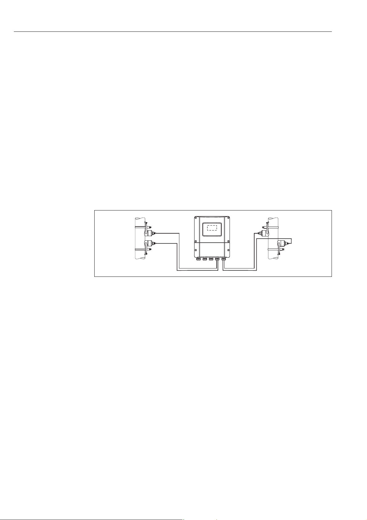
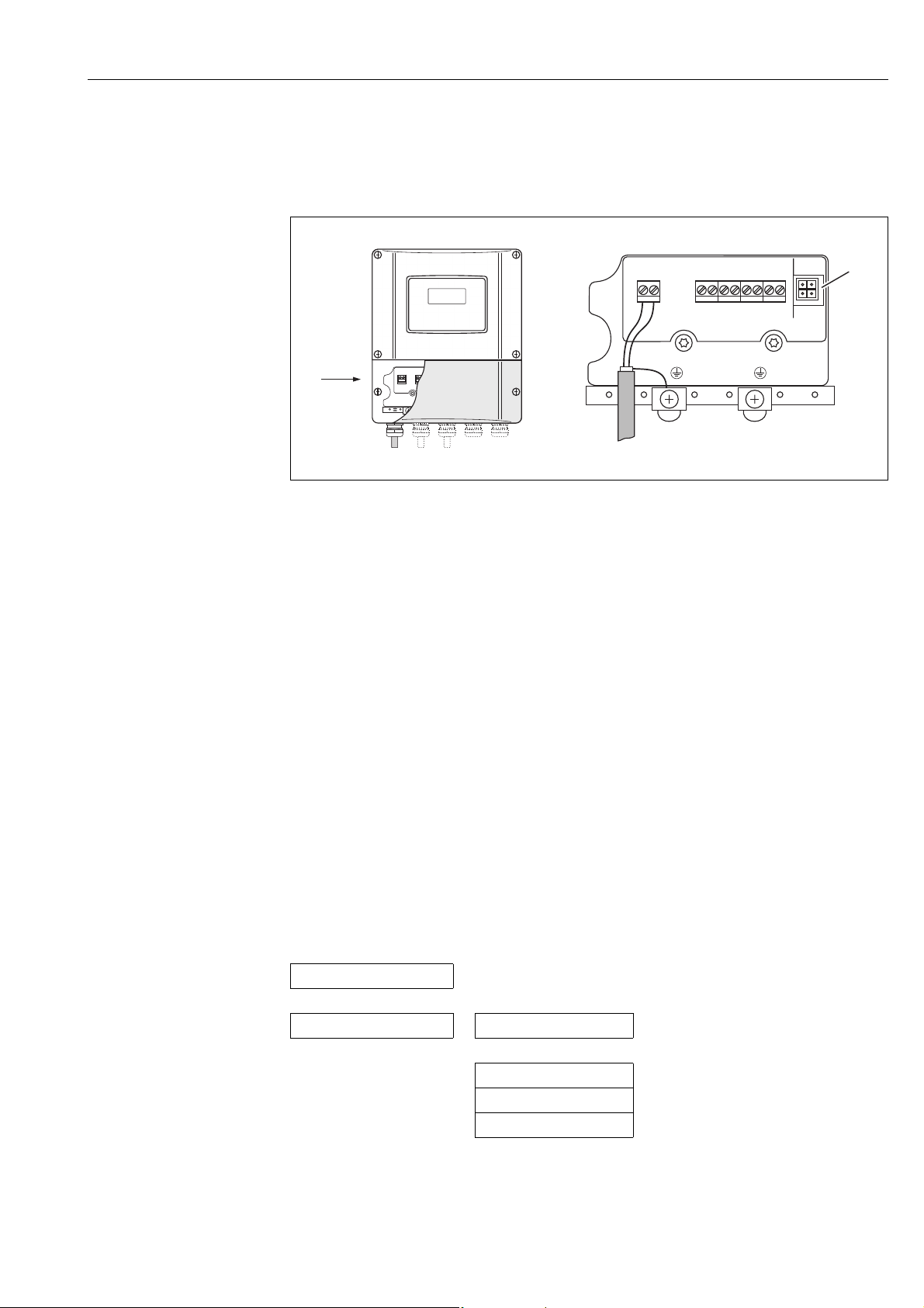
Connecting the PC to the plant asset management tool
A personal computer is connected to the FieldCare plant asset management tool via the service
interface FXA 193. The service interface FXA 193 is connected to the service connector of the
transmitter.
A0011365
Fig. 18: Connecting a PC with the FieldCare operating software
a Service adapter for connecting service interface FXA193
!
!
Switching on the measuring device
1. Perform the post-connection check as specified in the checklist ä 65.
2. Switch on the supply voltage for the device. The device performs internal test functions.
Various messages appear on the display.
3. Normal measuring mode commences. Various measured value and/or status variables appear
on the display (HOME position).
Note!
If startup fails, an appropriate error message is displayed, depending on the cause ä 105.
Reading off the installation distances via FieldCare
Note!
The following section only illustrates the functions necessary for clamp-on and insertion type of
mounting.
Reading off installation distances via FieldCare for clamp-on type of mounting
1. Enter or select installation-specific values or the values specified here.
2. Read off the installation distances necessary for mounting.
Basic function
Sensor data K1/K2 Sensor parameter
Clamp-on Measurement
Sensor type
1 or 2 Sensor configuration = Number of traverses
Endress+Hauser 25
Page 26

Installation Proline Prosonic Flow 93
Basic function
Process parameter K1/K2 Pipe data
Pipe standard
Nominal diameter
Pipe material
Sound velocity pipe
Circumference
Pipe diameter
Wall thickness
Liner material
Basic function
Process parameter K1/K2 Liquid data
Liquid
Temperature
Sound velocity liquid
Basic function
Process parameter K1/K2 Sensor parameter
Position sensor –
Wire length –
Sensor distance
Installation
distances for
measurement
via one traverse:
Installation
distances for
measurement via
two traverses:
Subsequent procedure
The sensors can be installed once the installation distances have been determined:
• Prosonic Flow P or W (DN 15 to 65 / ½ to 2½") ä 35
• Prosonic Flow P (DN 50 to 4000 / 2 to 160") ä 37
• Prosonic Flow W (Clamp-on) ä 41
26 Endress+Hauser
Page 27

Proline Prosonic Flow 93 Installation
Reading off installation distances via FieldCare for insertion type of mounting
1. Enter or select installation-specific values or the values specified here.
2. Read off the installation distances necessary for mounting.
Basic function
Sensor data K1/K2 Sensor parameter
Insertion Measurement
Sensor type
Single-path or dual-path Sensor configuration = Number of paths
Basic function
Process parameter K1/K2 Pipe data
Pipe standard
Nominal diameter
Circumference
Pipe diameter
Wall thickness
Basic function
Process parameter K1/K2 Sensor parameter
Sensor distance
Arc length –
Path length –
Installation
distances for
measurement
via one traverse:
Installation
distances for
measurement via
two traverses:
Subsequent procedure
The sensors can be installed once the installation distances have been determined:
•Prosonic Flow W ä 45.
Endress+Hauser 27
Page 28

Installation Proline Prosonic Flow 93
3.6.3 Determining installation distances via Applicator
Applicator is a software application for selecting and planning flowmeters. The installation distances
required for installation can be determined without having to commision the transmitter
beforehand.
Applicator is available:
• On a CD-ROM for installation on a local PC ä 104.
• Via the Internet for direct online entry www.endress.com select country.
On the Internet site, select Instruments Flow Tooling Applicator. In the "Applicator
Sizing Flow" field, select the "Start Applicator Sizing Flow online" link.
Determining installation distances for clamp-on, measuring via one traverse
Determine the installation distances required via Applicator:
• Select the fluid.
• Select the device (e.g. 93P Clamp-on).
• Enter or select measuring point-specific values.
• Select the number of traverses: 1
• Read off the necessary installation distances:
– Wire length: __________
– Sensor distance: __________
Subsequent procedure
The sensors can be installed once the installation distances have been determined:
• Prosonic Flow P (DN 50 to 4000 / 2 to 160") ä 37
•Prosonic Flow W ä 41.
Determining installation distances for clamp-on, measuring via two traverses
Determine the installation distances required via Applicator:
• Select the fluid.
• Select the device (e.g. 93P Clamp-on).
• Enter or select measuring point-specific values.
• Select the number of traverses: 2
• Read off the necessary installation distances:
– Sensor position: __________
– Sensor distance: __________
Subsequent procedure
The sensors can be installed once the installation distances have been determined:
• Prosonic Flow P or W (DN 15 to 65 / ½ to 2½") ä 39
• Prosonic Flow P (DN 50 to 4000 / 2 to 160") ä 39
•Prosonic Flow W ä 43.
Determining installation distances for insertion version, single-path measurement
Determine the installation distances required via Applicator:
• Select the fluid.
• Select the device (e.g. 93W Insert 1Ch).
• Enter or select measuring point-specific values.
• Read off the necessary installation distance:
– Sensor distance: __________
Subsequent procedure
The sensors can be installed once the installation distances have been determined:
•Prosonic Flow W ä 46.
28 Endress+Hauser
Page 29

Proline Prosonic Flow 93 Installation
Determining installation distances for insertion version, dual-path measurement
Determine the installation distances required via Applicator:
• Select the fluid.
• Select the device (e.g. 93W Insert 2Ch).
• Enter or select measuring point-specific values.
• Read off the necessary installation distances:
– Sensor distance: __________
– Arc length: __________
Subsequent procedure
The sensors can be installed once the installation distances have been determined:
•Prosonic Flow W ä 41.
Endress+Hauser 29
Page 30
Installation Proline Prosonic Flow 93
A
3.7 Mechanical preparation
The way in which the sensors are secured differs on account of the pipe nominal diameter and the
sensor type. Depending on the type of sensor, users also have the option of securing the sensors with
strapping bands or screws such that they can be later removed, or permanently fixing the sensors in
place with welded bolts or welded retainers.
Overview of possible ways to secure the various sensors:
Prosonic Flow For the measuring range Pipe nominal
93W/93P DN 15 to 65
(½ to 2½")
93P DN 50 to 4000
(2 to 160")
93W DN 50 to 4000
(2 to 160")
diameter
DN 32 (1¼") Sensor holder with U-shaped screws ä 30
DN 32 (1¼") Sensor holder with strapping bands ä 31
DN 200 (8") Strapping bands (medium nominal diameters) ä 32
DN 200 (8") Strapping bands (large nominal diameters) ä 33
DN 200 (8") Strapping bands (medium nominal diameters) ä 32
DN 200 (8") Strapping bands (large nominal diameters) ä 33
Secured by
Welded bolts ä 34
Welded bolts ä 34
Welded bolts ä 34
Welded bolts ä 31
Insertion version ä 45
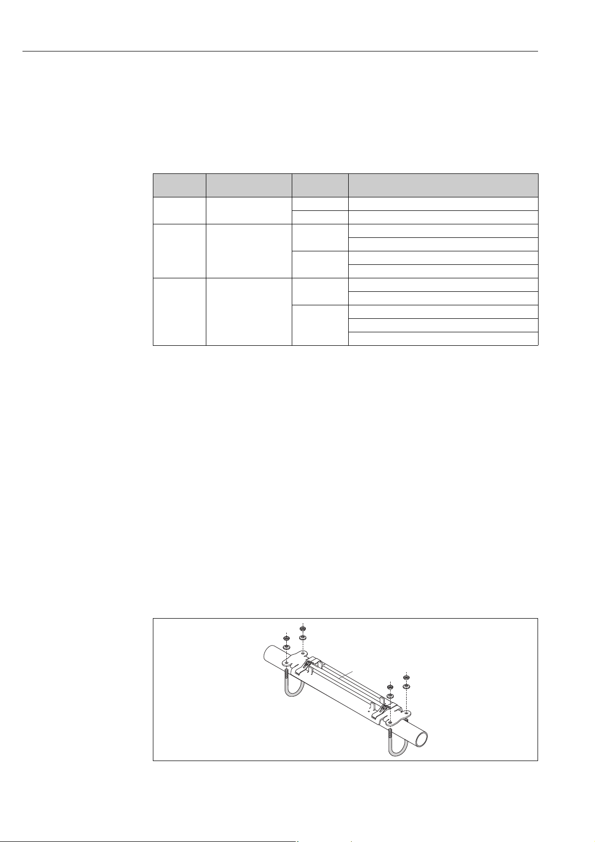
3.7.1 Mounting the sensor holder with U-shaped screws
For mounting on a pipe with a nominal diameter of DN 32 (1¼")
For sensors: Prosonic Flow 93W or P (DN 15 to 65 / ½ to 2½")
Procedure
1. Disconnect the sensor from the sensor holder.
2. Position the sensor holder on the pipe.
3. Put the U-shaped screws through the sensor holder and slightly lubricate the thread.
!
4. Screw nuts onto the U-shaped screws.
5. Set the holder to the exact position and tighten the nuts evenly.
Warning!
#
Risk of damaging plastic or glass pipes if the nuts of the U-shaped screws are tightened too
much! The use of a metal half-shell is recommended (on the opposite side of the sensor) when
working with plastic or glass pipes.
Note!
The visible pipe surface "A" must be smooth to ensure good accustic contact.
Fig. 19: Mounting the Prosonic Flow P or W sensor holder (DN 15 to 65 / ½ to 2½") with U-shaped screws
A0011XXXX
30 Endress+Hauser
Page 31

Proline Prosonic Flow 93 Installation
A
A
3.7.2 Mounting the sensor holder with strapping bands
For mounting on a pipe with a nominal diameter of DN 32 (1¼")
For sensors:
• Prosonic Flow 93W or P (DN 15 to 65 / ½ to 2½")
Procedure
1. Disconnect the sensor from the sensor holder.
2. Position the sensor holder on the pipe.
3. Wrap the strapping bands around the sensor holder and pipe without twisting them.
4. Guide the strapping bands through the strapping band locks (strapping screw is pushed up).
5. Tighten the strapping bands as tight as possible by hand.
6. Set the sensor holder to the correct position.
7. Push down the strapping screw and tighten the strapping bands so that they cannot slip.
8. Where necessary, shorten the strapping bands and trim the cut edges.
#
!
Warning!
Risk of injury. To avoid sharp edges, trim the cut edges after shortening the strapping bands.
A0011525
Fig. 20: Positioning the sensor holder and mounting the strapping bands
Note!
The visible pipe surface "A" must be smooth to ensure good accustic contact.
Endress+Hauser 31
A0011526
Fig. 21: Tightening the strapping screws of the strapping bands
Page 32

Installation Proline Prosonic Flow 93
1
2
3
3.7.3 Premounting the strapping bands (medium nominal diameters)
When mounting on a pipe with a nominal diameter of DN 200 (8")
For sensors:
• Prosonic Flow 93W or P (DN 50 to 4000 / 2 to 160")
Procedure
First strapping band
1. Fit the mounting bolt over the strapping band.
2. Wrap the strapping band around the pipe without twisting it.
3. Guide the end of the strapping band through the strapping band lock (strapping screw is
pushed up).
4. Tighten the strapping band as tight as possible by hand.
5. Set the strapping band to the desired position.
6. Push down the strapping screw and tighten the strapping band so that it cannot slip.
Second strapping band
7. Proceed as for the first strapping band (steps 1 to 7). Only slightly tighten the second strapping
band for final mounting. It must be possible to move the strapping band for final alignment.
#
Both strapping bands
8. Where necessary, shorten the strapping bands and trim the cut edges.
Warning!
Risk of injury. To avoid sharp edges, trim the cut edges after shortening the strapping bands.
A0001109
Fig. 22: Premounting strapping bands for pipe diameters DN 200 (8")
1 Mounting bolt
2 Strapping band
3 Strapping screw
32 Endress+Hauser
Page 33

Proline Prosonic Flow 93 Installation
3.
500 mm (20 in)
3.7.4 Premounting the strapping bands (large nominal diameters)
When mounting on a pipe with a nominal diameter in the range of
DN 600 (24")
For sensors:
• Prosonic Flow 93W or P (DN 50 to 4000 / 2 to 160")
Procedure
1. Measure the pipe circumference.
2. Shorten the strapping bands to one length (pipe circumference + 32 cm (12.6 in)) and trim the
cut edges.
Warning!
#
Risk of injury. To avoid sharp edges, trim the cut edges after shortening the strapping bands.
First strapping band
3. Fit the mounting bolt over the strapping band.
4. Wrap the strapping band around the pipe without twisting it.
5. Guide the end of the strapping band through the strapping band lock (strapping screw is
pushed up).
6. Tighten the strapping band as tight as possible by hand.
7. Set the strapping band to the desired position.
8. Push down the strapping screw and tighten the strapping band so that it cannot slip.
Second strapping band
9. Proceed as for the first strapping band (steps 3 to 8). Only slightly tighten the second strapping
band for final mounting. It must be possible to move the strapping band for final alignment.
A0015461
Fig. 23: Premounting strapping bands for pipe diameters DN > 600 (24")
1 Mounting bolt with guide*
2 Strapping band*
3 Strapping screw
* Distance between mounting bolt and strapping band lock min. 500 mm (20 in)
Endress+Hauser 33
Page 34

Installation Proline Prosonic Flow 93
M6
50
1
2
3
1
3.7.5 Mounting the welded bolts
When mounting on a pipe with a nominal diameter of DN 50 to 4000 (2 to 160")
For sensors:
• Prosonic Flow 93P (DN 50 to 4000 / 2 to 160")
• Prosonic Flow 93W
Procedure
The welded bolts must be fixed at the same installation distances as the mounting bolts with
strapping bands. The following sections explain how to the align the mounting bolts depending on
the type of mounting and the measurement method:
• Prosonic Flow P (DN 50 to 4000 / 2 to 160"), Clamp-on
– Installation for measurement via one traverse ä 37
– Installation for measurement via two traverses ä 39.
• Prosonic Flow W, Clamp-on
– Installation for measurement via one traverse ä 41
– Installation for measurement via two traverses ä 43.
The sensor holder is secured with a retaining nut with a metric ISO M6 thread as standard.
If you want to use another thread to secure the sensor holder, you must use a sensor holder with a
removable retaining nut (order number: 93WAx - xBxxxxxxxxxx).
A0001111
Fig. 24: Use of welded bolts
1 Welding seam
2 Retaining nut
3 Hole diameter max. 8.7 mm (0.34")
34 Endress+Hauser
Page 35

Proline Prosonic Flow 93 Installation
a
d
c
b
3.8 Installing Prosonic Flow W and P (DN 15 to 65 / ½ to 2½")
3.8.1 Mounting the sensor
Prerequisites
• The installation distance (sensor distance) is known ä 16.
• The sensor holder is already mounted ä 30.
Material
The following material is needed for mounting:
• Sensor incl. adapter cable
• Connecting cable for connecting to the transmitter
• Coupling fluid for an acoustic connection between the sensor and pipe
Procedure
1. Set the distance between the sensors as per the value determined for the sensor distance.
Press the movable sensor down slightly to move it.
!
A0011529
Fig. 25: Setting the distance between the sensors as per the value for the sensor distance
a Sensor distance (backside of sensor contact surface)
b Contact surfaces of the sensor
c Movable sensor
d Fixed sensor
2. Coat the contact surfaces of the sensors with an even layer of coupling fluid
(approx. 0.5 to 1 mm / 0.02 to 0.04") thick.
3. Fit the sensor housing on the sensor holder.
Note!
• Avoid to use a thick layer of the coupling fluid (less is more).
• Clean and reapply new coupling fluid when sensor is removed from the pipe.
• The sensor (DN 15 to 65 /½" to 2½") requires a smooth pipe surface.
Endress+Hauser 35
Page 36

Installation Proline Prosonic Flow 93
A0011527
Fig. 26: Fitting the sensor housing
4. Fix the sensor housing with the bracket.
Note!
!
– If necessary, the holder and sensor housing can be secured with a screw/nut or a
lead-seal (not part of the scope of supply).
– The bracket can only be released using an auxiliary tool.
A0011528
Fig. 27: Fixing the sensor housing
5. Connect the connecting cable to the adapter cable.
This completes the mounting process. The sensors can now be connected to the transmitter via the
connecting cables ä 61.
36 Endress+Hauser
Page 37

Proline Prosonic Flow 93 Installation
1234 567891011
SL
3.9 Installing Prosonic Flow P DN 50 to 4000 (2 to 160")
(Clamp-on)
3.9.1 Installation for measurement via one traverse
Prerequisites
• The installation distances (sensor distance and wire length) are known ä 16.
• The strapping bands are already mounted ä 30.
Material
The following material is needed for mounting:
• Two strapping bands incl. mounting bolts and centering plates where necessary
(already mounted ä 30)
• Two measuring wires, each with a cable lug and a fixer to position the strapping bands
•Two sensor holders
• Coupling fluid for an acoustic connection between the sensor and pipe
• Two sensors incl. connecting cables.
Procedure
1. Prepare the two measuring wires:
– Arrange the cable lugs and fixer such that the distance they are apart corresponds to the wire length (SL).
– Screw the fixer onto the measuring wire.
Fig. 28: Fixer (a) and cable lugs (b) at a distance that corresponds to the wire length (SL)
2. With the first measuring wire:
– Fit the fixer over the mounting bolt of the strapping band that is already securely mounted.
– Run the measuring wire clockwise around the pipe.
– Fit the cable lug over the mounting bolt of the strapping band that can still be moved.
3. With the second measuring wire:
– Fit the cable lug over the mounting bolt of the strapping band that is already securely
mounted.
– Run the measuring wire counterclockwise around the pipe.
– Fit the fixer over the mounting bolt of the strapping band that can still be moved.
4. Take the still movable strapping band, incl. the mounting bolt, and move it until both
measuring wires are evenly tensioned and tighten the strapping band so that it cannot slip.
A0001112
Endress+Hauser 37
A0001113
Fig. 29: Positioning the strapping bands (steps 2 to 4)
Page 38

Installation Proline Prosonic Flow 93
5. Loosen the screws of the fixers on the measuring wires and remove the measuring wires from
the mounting bolt.
6. Fit the sensor holders over the individual mounting bolts and tighten securely with the retaining nut.
A0001114
Fig. 30: Mounting the sensor holders
7. Coat the contact surfaces of the sensors with an even layer of coupling fluid approx. 1 mm
(0.04") thick, going from the groove through the center to the opposite edge.
!
Note!
• Avoid to use a thick layer of the coupling fluid (less is more).
• Clean and reapply new coupling fluid when the sensor is removed from the pipe.
•
On rough pipe surface e.g. GRP pipes ensure that the gaps crevices within the surface roughness
are filled. Apply sufficient coupling fluid
Fig. 31: Coating the contact surfaces of the sensor with coupling fluid
.
8. Insert the sensor into the sensor holder.
9. Fit the sensor cover on the sensor holder and turn until:
– The sensor cover engages with a click
– The arrows (Å / Æ "close") are pointing towards one another.
10. Screw the connecting cable into the individual sensor.
A0011373
A0001115
Fig. 32: Mounting the sensor and connecting the connecting cable
38 Endress+Hauser
Page 39

Proline Prosonic Flow 93 Installation
G
22
This completes the mounting process. The sensors can now be connected to the transmitter via the
connecting cables ä 61.
3.9.2 Installation for measurement via two traverses
Prerequisites
• The installation distance (position sensor) is known ä 16.
• The strapping bands are already mounted ä 30.
Material
The following material is needed for mounting:
• Two strapping bands incl. mounting bolts and centering plates where necessary
(already mounted ä 30)
• A mounting rail to position the strapping bands
• Two mounting rail retainers
•Two sensor holders
• Coupling fluid for an acoustic connection between the sensor and pipe
• Two sensors incl. connecting cables.
Mounting rail and POSITION SENSOR installation distance
The mounting rail has two rows with bores. The bores in one of the rows are indicated by letters
and the bores in the other row are indicated by numerical values. The value determined for the
POSITION SENSOR installation distance is made up of a letter and a numerical value.
The bores that are identified by the specific letter and numerical value are used to position the
strapping bands.
Procedure
1. Position the strapping bands with the aid of the mounting rail.
– Slide the mounting rail with the bore identified by the letter from POSITION SENSOR over
the mounting bolt of the strapping band that is permanently fixed in place.
– Position the movable strapping band and slide the mounting rail with the bore identified by
the numerical value from POSITION SENSOR over the mounting bolt.
Fig. 33: Determining the distance in accordance with the mounting rail (e.g. POSITION SENSOR G22)
2. Tighten the strapping band so that it cannot slip.
3. Remove the mounting rail from the mounting bolt.
4. Fit the sensor holders over the individual mounting bolts and tighten securely with the
retaining nut.
5. Screw the retainers of the mounting rail onto the sensor holder in question.
6. Screw the mounting rail onto the sensor holders.
Endress+Hauser 39
A0001116
Page 40

Installation Proline Prosonic Flow 93
A0001156
Fig. 34: Mounting the sensor holders and mounting rail
7. Coat the contact surfaces of the sensors with an even layer of coupling fluid approx. 1 mm
(0.04") thick, going from the groove through the center to the opposite edge.
!
Note!
• Avoid to use a thick layer of the coupling fluid (less is more).
• Clean and reapply new coupling fluid when sensor is removed from the pipe.
• On rough pipe surfaces e.g. GRP pipes ensure that the gaps
crevices within the surface roughness
are
filled. Apply sufficient coupling fluid.
Fig. 35: Coating the contact surfaces of the sensor with coupling fluid
8. Insert the sensor into the sensor holder.
9. Fit the sensor cover on the sensor holder and turn until:
– The sensor cover engages with a click
– The arrows (Å / Æ "close") are pointing towards one another.
10. Screw the connecting cable into the individual sensor.
Fig. 36: Mounting the sensor and connecting the connecting cable
A0011XXX
A0001112
This completes the mounting process. The sensors can now be connected to the transmitter via the
connecting cables ä 61.
40 Endress+Hauser
Page 41

Proline Prosonic Flow 93 Installation
1234 567891011
SL
3.10 Installing Prosonic Flow W (Clamp-on)
3.10.1 Installation for measurement via one traverse
Prerequisites
• The installation distances (sensor distance and wire length) are known ä 16.
• The strapping bands are already mounted ä 30.
Material
The following material is needed for mounting:
• Two strapping bands incl. mounting bolts and centering plates where necessary
(already mounted ä 30)
• Two measuring wires, each with a cable lug and a fixer to position the strapping bands
•Two sensor holders
• Coupling fluid for an acoustic connection between the sensor and pipe
• Two sensors incl. connecting cables.
Procedure
1. Prepare the two measuring wires:
– Arrange the cable lugs and fixer such that the distance they are apart corresponds to the wire
length (SL).
– Screw the fixer onto the measuring wire.
Fig. 37: Fixer (a) and cable lugs (b) at a distance that corresponds to the wire length (SL)
2. With the first measuring wire:
– Fit the fixer over the mounting bolt of the strapping band that is already securely mounted.
– Run the measuring wire clockwise around the pipe.
– Fit the cable lug over the mounting bolt of the strapping band that can still be moved.
3. With the second measuring wire:
– Fit the cable lug over the mounting bolt of the strapping band that is already securely
mounted.
– Run the measuring wire counterclockwise around the pipe.
– Fit the fixer over the mounting bolt of the strapping band that can still be moved.
4. Take the still movable strapping band, incl. the mounting bolt, and move it until both
measuring wires are evenly tensioned and tighten the strapping band so that it cannot slip.
A0001112
Endress+Hauser 41
A0001113
Fig. 38: Positioning the strapping bands (steps 2 to 4)
Page 42

Installation Proline Prosonic Flow 93
5. Loosen the screws of the fixers on the measuring wires and remove the measuring wires from
the mounting bolt.
6. Fit the sensor holders over the individual mounting bolts and tighten securely with the
retaining nut.
A0001114
Fig. 39: Mounting the sensor holders
7. Coat the contact surfaces of the sensors with an even layer of coupling fluid approx. 1 mm
(0.04") thick, going from the groove through the center to the opposite edge.
!
Note!
• Avoid to use a thick layer of the coupling fluid (less is more).
• Clean and reapply new coupling fluid when sensor is removed from the pipe.
• On rough pipe surfaces e.g. GRP pipes ensure that the gaps
crevices within the surface roughness
filled. Apply sufficient coupling fluid.
Fig. 40: Coating the contact surfaces of the sensor with coupling fluid
8. Insert the sensor into the sensor holder.
9. Fit the sensor cover on the sensor holder and turn until:
– The sensor cover engages with a click
– The arrows (Å / Æ "close") are pointing towards one another.
10. Screw the connecting cable into the individual sensor.
are
A0011373
A0001115
Fig. 41: Mounting the sensor and connecting the connecting cable
This completes the mounting process. The sensors can now be connected to the transmitter via the
connecting cables ä 61.
42 Endress+Hauser
Page 43

Proline Prosonic Flow 93 Installation
G
22
3.10.2 Installation for measurement via two traverses
Prerequisites
• The installation distance (position sensor) is known ä 16.
• The strapping bands are already mounted ä 30.
Material
The following material is needed for mounting:
• Two strapping bands incl. mounting bolts and centering plates where necessary
(already mounted ä 30)
• A mounting rail to position the strapping bands
• Two mounting rail retainers
•Two sensor holders
• Coupling fluid for an acoustic connection between the sensor and pipe
• Two sensors incl. connecting cables.
Mounting rail and POSITION SENSOR installation distance
The mounting rail has two rows with bores. The bores in one of the rows are indicated by letters
and the bores in the other row are indicated by numerical values. The value determined for the
POSITION SENSOR installation distance is made up of a letter and a numerical value.
The bores that are identified by the specific letter and numerical value are used to position the
strapping bands.
Procedure
1. Position the strapping bands with the aid of the mounting rail.
– Slide the mounting rail with the bore identified by the letter from POSITION SENSOR over
the mounting bolt of the strapping band that is permanently fixed in place.
– Position the movable strapping band and slide the mounting rail with the bore identified by
the numerical value from POSITION SENSOR over the mounting bolt.
Fig. 42: Determining the distance in accordance with the mounting rail (e.g. POSITION SENSOR G22)
2. Tighten the strapping band so that it cannot slip.
3. Remove the mounting rail from the mounting bolt.
4. Fit the sensor holders over the individual mounting bolts and tighten securely with the
retaining nut.
A0001116
Endress+Hauser 43
Page 44

Installation Proline Prosonic Flow 93
A0001117
Fig. 43: Mounting the sensor
5. Coat the contact surfaces of the sensors with an even layer of coupling fluid approx. 1 mm
(0.04") thick, going from the groove through the center to the opposite edge.
!
Note!
• Avoid to use a thick layer of the coupling fluid (less is more).
• Clean and reapply new coupling fluid when sensor is removed from the pipe.
• On rough pipe surfaces e.g. GRP pipes ensure that the gaps
crevices within the surface roughness
are
filled. Apply sufficient coupling fluid.
Fig. 44: Coating the contact surfaces of the sensor with coupling fluid
6. Insert the sensor into the sensor holder.
7. Fit the sensor cover on the sensor holder and turn until:
– The sensor cover engages with a click
– The arrows (Å / Æ "close") are pointing towards one another.
8. Screw the connecting cable into the individual sensor.
Fig. 45: Connecting the connecting cable
A0011373
A0011376
44 Endress+Hauser
Page 45

Proline Prosonic Flow 93 Installation
a
c
1
d
a
c
2
α
d
b
α
This completes the mounting process. The sensors can now be connected to the transmitter via the
connecting cables ä 61.
3.11 Installing Prosonic Flow W (Insertion version)
The graphic below provides you with an overview of the terms used when installing a
Prosonic Flow W (Insertion version).
Fig. 46: Explanation of terms
1 Single-path version
2Dual-path version
a Sensor distance
bArc length
c Path length
d Pipe outer diameter (is determined by the application)
A0013926
Endress+Hauser 45
Page 46

Installation Proline Prosonic Flow 93
e
3.11.1 Installation for measurement as single-path insertion version
1. Determine the installation area (e) on the pipe section:
– Mounting location ä 11
– Inlet/outlet run ä 12
– Space required by the measuring point: approx. 1x pipe diameter.
2. Mark the middle line on the pipe at the mounting location and mark the position of the first
drillhole (drillhole diameter: 65 mm / 2.56").
Note!
!
Make the middle line longer than the drillhole!
A0001124
Fig. 47: Installing the measuring sensors, steps 1 and 2
3. Cut the first hole, e.g. with a plasma cutter. Measure the wall thickness of the pipe if it is not
known.
4. Determine the sensor distance.
Note!
!
Determine the sensor distance as follows:
– Via the Quick Setup "Sensor Installation" for measuring devices with local operation.
Run the Quick Setup as described on ä 84. The sensor distance is displayed in the
SENSOR DISTANCE function. The transmitter must be installed and connected to the
power supply before you can run the "Sensor Installation" Quick Setup.
– As explained on ä 85 for transmitters without local operation.
A0001125
Fig. 48: Installing the measuring sensors, steps 3 and 4
5. Draw the sensor distance (a) starting from the middle line of the first drillhole.
46 Endress+Hauser
Page 47

Proline Prosonic Flow 93 Installation
6. Project the middle line to the back of the pipe and draw it on.
A0001126
Fig. 49: Installing the measuring sensors, steps 5 and 6
7. Mark the drillhole on the middle line on the back of the pipe.
8. Cut out the second drillhole and prepare the holes for welding the sensor holders, (deburr,
clean, etc.).
A0001127
Fig. 50: Installing the measuring sensors, steps 7 and 8
9. Insert the sensor holders into the two drillholes. To adjust the weld-in depth, you can fix both
sensor holders with the special tool for insertion depth regulation (optional) and then align
using the tie rod. The sensor holder must be flush with the inner side of the pipe.
10. Spot-weld both sensor holders.
Note!
!
To align the tie rod, you have to screw two guide bushings into the sensor holders.
A0001128
Fig. 51: Installing the measuring sensors, steps 9 and 10
Endress+Hauser 47
Page 48

Installation Proline Prosonic Flow 93
11. Weld in both sensor holders.
12. Check the distance between the drillholes once again and determine the path length.
Note!
!
Determine the path length as follows:
– Via the Quick Setup "Sensor Installation" for measuring devices with local operation.
Run the Quick Setup as described on ä 84. The path length is displayed in the PATH
LENGTH function. The transmitter must be installed and connected to the power supply
before you can run the "Sensor Installation" Quick Setup.
– As explained on ä 85 for transmitters without local operation.
13. Screw the sensors into the sensor holders by hand. If you use a tool, the maximum torque
permissible is 30 Nm.
14. Insert the sensor cable connectors into the opening provided and manually tighten the
connectors to the stop.
Fig. 52: Installing the measuring sensors, steps 11 to 14
A0001129
48 Endress+Hauser
Page 49

Proline Prosonic Flow 93 Installation
e
b
3.11.2 Installation for measurement as dual-path insertion version
1. Determine the installation area (e) on the pipe section:
– Mounting location ä 11
– Inlet/outlet run ä 12
– Space required by the measuring point: approx. 1× pipe diameter.
2. Mark the middle line on the pipe at the mounting location.
A0001124
Fig. 53: Installing the dual-path measuring sensors, steps 1 and 2
3. At the mounting location of the sensor holder, mark the length of the arc (b) to one side of the
middle line. Usually, the arc length is taken as approx. 1/12 of the pipe circumference.
Indicate the first drillhole (drillhole diameter approx. 81 to 82 mm / 3.19 to 3.23").
Note!
!
Make the lines longer than the drillhole!
4. Cut the first hole, e.g. with a plasma cutter. Measure the wall thickness of the pipe if it is not
known.
A0001162
Fig. 54: Installing the dual-path measuring sensors, steps 3 and 4
5. Determine the space between the distancing holes (sensor distance) and the arc length
between the sensors of the measuring groups.
Note!
!
Determine the sensor distance as follows:
– Via the Quick Setup "Sensor Installation" for measuring devices with local operation.
Run the Quick Setup as described on ä 84. The sensor distance is displayed in the
SENSOR DISTANCE function (6886) and the arc length in the ARC LENGTH function
(6887). The transmitter must be installed and connected to the power supply before you can
run the "Sensor Installation" Quick Setup.
– As explained on ä 85 for transmitters without local operation.
Endress+Hauser 49
Page 50

Installation Proline Prosonic Flow 93
a
CH 1
CH 2
CH 2
CH 1
6. You can correct the middle line with the arc length determined.
A0001163
Fig. 55: Installing the dual-path measuring sensors, steps 5 and 6
7. Project the corrected middle line onto the other side of the pipe and draw this on (half pipe
circumference).
8. Indicate the sensor distance on the middle line and project it onto the middle line on the back.
A0001164
Fig. 56: Installing the dual-path measuring sensors, steps 7 and 8
9. Extend the arc length to each side of the middle line and indicate the drillholes.
10. Create the drillholes and prepare the holes for welding in the sensor holder (deburr, clean,
etc.).
Note!
!
Drillholes for the sensor holders always come in pairs (CH 1 - CH 1 and CH 2 - CH 2).
Fig. 57: Installing the dual-path measuring sensors, steps 9 and 10
50 Endress+Hauser
A0001165
Page 51

Proline Prosonic Flow 93 Installation
11. Insert the sensor holders into the first pair of drillholes and align with the tie rod (alignment
tool). Spot-weld with the wedding apparatus and then permanently weld both sensor holders.
Note!
!
To align the tie rod, two guide bushings must be screwed onto the sensor holders.
A0001166
Fig. 58: Installing the dual-path measuring sensors, step 11
12. Weld in both sensor holders.
13. Check the path length, sensor distances and arc lengths once again.
Note!
!
These distances are given as a measurement in Quick Setup. If you determine deviations, note
these down and enter them as correction factors when commissioning the measuring point.
14. Insert the second pair of sensor holders into the two remaining drillholes, as described in
step 12 .
Fig. 59: Installing the dual-path measuring sensors, steps 13 and 14
A0001167
A0001168
Fig. 60: Installing the dual-path measuring sensors, step 13
Endress+Hauser 51
Page 52

Installation Proline Prosonic Flow 93
15. Then screw the sensors into the sensor holders by hand. If you use a tool, the maximum torque
permissible is 30 Nm.
16. Insert the sensor cable connectors into the opening provided and manually tighten the
connectors to the stop.
A0001169
Fig. 61: Installing the dual-path measuring sensors, step 14 and 15
52 Endress+Hauser
Page 53

Proline Prosonic Flow 93 Installation
3.12 Installing sensor DDU18
1. Premount the strapping band:
– Nominal diameters DN 200 (8") ä 32
– Nominal diameters DN 200 (8") ä 33
The two mounting bolts must be positioned opposite each other on either side of the pipe.
2. Fit the sensor holders over the individual mounting bolts and tighten securely with the
retaining nut.
3. Coat the contact surfaces of the sensors with an even layer of coupling fluid approx. 1 mm
(0.04") thick, going from the groove through the center to the opposite edge.
4. Insert the sensor into the sensor holder.
5. Fit the sensor cover on the sensor holder and turn until:
– The sensor cover engages with a click
– The arrows (Å / Æ "close") are pointing towards one another.
6. Screw the connecting cable into the individual sensor.
A0001171
Fig. 62: Steps 1 to 5, installing the sound velocity measuring sensors
Endress+Hauser 53
Page 54

Installation Proline Prosonic Flow 93
3.13 Installing sensor DDU19
3.13.1 Version 1
1. Premount the strapping band:
– Nominal diameters DN 200 (8") ä 32
– Nominal diameters DN 200 (8") ä 33
The two mounting bolts must be positioned opposite each other on either side of the pipe.
2. Fit the sensor holders over the individual mounting bolts and tighten securely with the
retaining nut.
3. Coat the contact surfaces of the sensors with an even layer of coupling fluid approx. 1 mm
(0.04") thick, going from the groove through the center to the opposite edge.
4. Insert the sensor into the sensor holder.
5. Fit the sensor cover on the sensor holder and turn until:
– The sensor cover engages with a click
– The arrows (Å / Æ "close") are pointing towards one another.
6. Screw the connecting cable into the connections of the sensor.
7. After determining the pipe wall thickness, replace the wall thickness sensor DDU19 with the
appropriate flow sensor.
!
Note!
Clean the coupling point carefully before the flow sensor coated with new coupling fluid is inserted.
3.13.2 Version 2
This is only suitable if the transmitter is within range of the measuring point.
1. Coat the contact surfaces of the sensors with an even layer of coupling fluid approx. 1 mm
(0.04") thick, going from the groove through the center to the opposite edge.
2. Hold the sensor vertically by hand on the pipe for measurement. Operate the local operation
with your other hand.
A0008665
Fig. 63: Installing the wall thickness measuring sensor
54 Endress+Hauser
Page 55

Proline Prosonic Flow 93 Installation
a
b
c
c
90 (3.54)
35 (1.38)
192 (7.56)
81.5(3.2)
mm (inch)
3.14 Installing the wall-mount transmitter housing
There are various ways of installing the wall-mount housing:
• Direct wall mounting
• Panel mounting (with separate mounting kit, accessories) ä 101
• Pipe mounting (with separate mounting kit, accessories) ä 101
Caution!
"
• Make sure that the permitted operating temperature range
(-20 to +60 °C / –4 to 140 °F) is not exceeded at the mounting location. Install the device in a
shady location. Avoid direct sunlight.
• Always install the wall-mount housing in such a way that the cable entries are pointing down.
3.14.1 Direct wall mounting
1. Drill the holes ä 55.
2. Remove the cover of the connection compartment (a).
3. Push the two securing screws (b) through the appropriate bores (c) in the housing.
– Securing screws (M6): max. Ø 6.5 mm (0.26")
– Screw head: max. Ø 10.5 mm (0.41")
4. Secure the transmitter housing to the wall as indicated.
5. Screw the cover of the connection compartment (a) firmly onto the housing.
Fig. 64: Direct wall mounting
Endress+Hauser 55
A0001130
Page 56

Installation Proline Prosonic Flow 93
245(9.65)
~110 (~4.33)
210 (8.27)
+0.5 (+0.019)
–0.5(–0.019)
+0.5 (+0.019)
–0.5(–0.019)
mm (inch)
Ø 20…70
(Ø 0.79…2.75)
~~6.1)155 (
mm (inch)
3.14.2 Panel mounting
1. Prepare the opening in the panel å 65.
2. Slide the housing into the panel cutout from the front.
3. Screw the retainers onto the wall-mount housing.
4. Screw the threaded rods into the retainers and tighten until the housing is solidly seated on the
panel wall. Tighten the counter nuts. No further support is necessary.
Fig. 65: Panel mounting (wall-mount housing)
3.14.3 Pipe mounting
The assembly should be performed by following the instructions on ä 56.
Caution!
"
If a warm pipe is used for installation, make sure that the housing temperature does not exceed the
max. permitted value of +60 °C (+140 °F).
A0001131ae
Fig. 66: Pipe mounting (wall-mount housing)
56 Endress+Hauser
A0001132
Page 57

Proline Prosonic Flow 93 Installation
3.15 Post-installation check
Perform the following checks after installing the measuring device on the pipe:
Device condition and specifications Notes
Is the device damaged (visual inspection)? –
Does the device correspond to specifications at the measuring point, including
process temperature, ambient temperature, measuring range, etc.?
Installation Notes
Are the measuring point number and labeling correct (visual inspection)? –
Process environment / process conditions Notes
Have the inlet and outlet runs been observed? ä 12
Is the measuring device protected against moisture and direct sunlight? –
ä 125
Endress+Hauser 57
Page 58

Wiring Proline Prosonic Flow 93
4 Wiring
#
#
!
Warning!
When connecting Ex-certified devices, please refer to the notes and diagrams in the Ex-specific
supplement to these Operating Instructions. Please do not hesitate to contact your Endress+Hauser
sales office if you have any questions.
4.1 Sensor/transmitter connecting cable
Warning!
• Risk of electric shock. Switch off the power supply before opening the device. Do not install or
wire the device while it is connected to the power supply. Failure to comply with this precaution
can result in irreparable damage to the electronics.
• Risk of electric shock. Connect the protective ground to the ground terminal on the housing
before the power supply is applied.
Note!
To ensure correct measuring results, route the cable well clear of electrical machines and switching
elements.
4.1.1 Connecting and grounding Prosonic Flow W and P
(DN 50 to 4000 / 2 to 160") Two Single coaxial cables
Procedure ä 59
1. Remove the cover (a) of the connection compartment.
2. Remove the dummy cover from the cable entry (b).
3. Route the two connecting cables (c) of channel 1 through the cable gland (d).
4. Route the two connecting cables of channel 1 through the cable entry (b) and into the
connection compartment of the transmitter.
5. Place the cable retaining sleeves (e) of the two connecting cables at the ground contact
terminals (f) (Detail B).
6. Twist down the ground contact terminals (f) so that the two cable retaining sleeves (e) are
firmly seated.
7. Screw the ground contact terminals (f) tight.
Note!
!
The Prosonic Flow W and Prosonic Flow P DN 15 to 65 (½ to 2½") is grounded via the cable
gland ä 60.
8. Connect the connecting cable:
– Channel 1 upstream = 1
– Channel 1 downstream = 2
– Channel 2 upstream = 3
– Channel 3 downstream = 4
9. Spread the rubber seal (g) along the side slit with a suitable tool (e.g. a large screwdriver) and
fix both connecting cables into place.
10. Push the rubber seal (g) up into the cable entry (b).
11. Tighten the cable gland (d).
12. Fit the cover (a) on the connection compartment and screw it on.
Note!
!
The connection compartment does not have to be assembled if the transmitter is wired (power
supply and signal cable) directly afterwards.
58 Endress+Hauser
Page 59

Proline Prosonic Flow 93 Wiring
A
1
A
32 4
d
g
e
c
f
B
b
a
A0008654
Fig. 67: Connecting the connecting cable for sensor/transmitter (with cable gland for two connecting cables per cable
AView A
B Detail B
1 Sensor cable connector, channel 1 upstream
2 Sensor cable connector, channel 1 downstream
3 Sensor cable connector, channel 2 upstream
4 Sensor cable connector, channel 2 downstream
a Connection compartment cover
b Cable entries
c Connecting cables
d Cable gland
e Cable retaining sleeves
f Ground contact terminals (only Prosonic Flow P DN 50 to 4000 / 2 to 160",
g Rubber seal
entry)
for grounding of the Prosonic Flow P DN 15 to 65 / ½ to 2½", see next section)
Endress+Hauser 59
Page 60

Wiring Proline Prosonic Flow 93
40 mm
15 mm
1
2
4
6
7
5
3
4.1.2 Connecting and Grounding Prosonic Flow W and Prosonic Flow P
DN 15 to 65 (½ to 2½") Multicore cable
The Prosonic Flow W/P DN 15 to 65 (½ to 2½") is grounded via the cable gland.
a0015587
Fig. 68: Connecting and grounding the measuring system
A Cable sheath
B Bared braided screen (pre-prepared)
C Rubber grommet
D Internal contact point for the grounding on this level (External inspection not possible)
E Cable gland
F Cable gland cover
G Grounding mechanism
!
!
Procedure
1. Screw the cable gland (E) into the transmitter housing.
2. Guide the sensor connecting cables through the cable gland cover (F).
3. Threat the sensor connecting cables into the transmitter housing.
Align the outer end of the rubber grommet with the end of the cable gland/grounding
mechanism. This ensures that the cable entry will be a) tight and b) the cable is correctly
grounded to the transmitter housing at the internal contact point (D) once tightended.
An external inspection is not possible, so it is important to follow this instruction.
4. Tighten the cable gland by turning the cable gland cover clockwise.
Note!
The red marked cable is sensor "up"; the blue marked cable is sensor "down".
Note!
The cable gland can be released from the cable by unscrewing and removing tha cable gland cover.
Then retract the grounding mechanism (G) with pair of pliers. The retraction of the mechanism does
not require strong force (strong force might destroy the screen). It might be required to lift the
internal hooks of the grounding mechanism out of a locked position by pressing the grounding
mechanism further forward by turning the cable gland clockwise. Remove the cable gland cover
again. Then retry to retract with the pair of pliers.
60 Endress+Hauser
Page 61

Proline Prosonic Flow 93 Wiring
1
2
cd
e
a
abb
f
+
22
–
23
+
20
–
21
+
24
–
25
+
26
–
27
L1 (L+)
N(L-)
4.1.3 Cable specification for connecting cable
Only use the connecting cables supplied by Endress+Hauser.
The connecting cables are available in different lengths ä 101.
For the cable specifications, see ä 122.
Operation in areas with strong electrical interference
The measuring system complies with the general safety requirements in accordance with
EN 61010, the EMC requirements of IEC/EN 61326 "Emission as per Class A requirements" and
NAMUR Recommendation NE 21.
4.2 Connecting the measuring unit
4.2.1 Connecting the transmitter
#
Warning!
• Risk of electric shock. Switch off the power supply before opening the device. Do not install or
wire the device while it is connected to the power supply. Failure to comply with this precaution
can result in irreparable damage to the electronics.
• Risk of electric shock. Connect the protective ground to the ground terminal on the housing
before the power supply is applied (not required for galvanically isolated power supply).
• Compare the specifications on the nameplate with the local supply voltage and frequency.
Furthermore, the national regulations governing the installation of electrical equipment also
apply.
1. Unscrew the connection compartment cover (f) from the transmitter housing.
2. Route the power supply cable (a) and signal cable (b) through the appropriate cable entries.
3. Wire the unit:
– Wiring diagram (wall-mount housing) ä 61
– Terminal assignment ä 62
4. Screw the cover of the connection compartment (f) back onto the transmitter housing.
Fig. 69: Connecting the transmitter (wall-mount housing). Cable cross-section: max. 2.5 mm2 (14 AWG)
a Cable for power supply: 85 to 260 V AC, 20 to 55 V AC, 16 to 62 V DC
b Signal cable: Terminals No. 20–27 ä 62
c Ground terminal for protective ground
d Ground terminal for signal cable shield
f Connection compartment cover
Terminal No. 1: L1 for AC, L+ for DC
Terminal No. 2: N for AC, L- for DC
Service adapter for connecting service interface FXA193 (FieldCare)
A0001135
Endress+Hauser 61
Page 62

Wiring Proline Prosonic Flow 93
4.2.2 Terminal assignment
The inputs and outputs on the communication board can be either permanently assigned (fixed) or
variable (flexible), depending on the version ordered (see table). Replacements for modules which
are defective or which have to be replaced can be ordered as accessories.
Order variant Terminal No. (inputs/outputs)
20 (+) / 21 (–) 22 (+) / 23 (–) 24 (+) / 25 (–) 26 (+) / 27 (–)
Fixed communication boards (fixed assignment)
93***-***********A – – Frequency output Current output HART
93***-***********B Relay output 2 Relay output 1 Frequency output Current output HART
93***-***********F
93***-***********G
93***-***********H – – – PROFIBUS PA
93***-***********J – – – PROFIBUS DP
93***-***********K – – – FOUNDATION Fieldbus
93***-***********S
93***-***********T
Flexible communication boards
93***-***********C Relay output 2 Relay output 1 Frequency output Current output HART
93***-***********D Status input Relay output Frequency output Current output HART
93***-***********L Status input Relay output 2 Relay output 1 Current output HART
93***-***********M Status input Frequency output Frequency output Current output HART
93***-***********P Current output Frequency output Status input PROFIBUS DP
93***-***********V Relay output 2 Relay output 1 Status input PROFIBUS DP
93***-***********W Relay output Current output Current output Current output HART
93***-***********2 Relay output Current output Frequency output Current output HART
93***-***********4 Current input Relay output Frequency output Current output HART
93***-***********6 Relay output Relay output Current output Current output HART
1
These options available for Prosonic Flow 93P only.
1
1
1
1
– – – PROFIBUS PA, Ex i
– – – FOUNDATION Fieldbus, Ex i
– – Frequency output, Ex i Current output, Ex i,
passive, HART
– – Frequency output, Ex i Current output, Ex i,
passive, HART
62 Endress+Hauser
Page 63

Proline Prosonic Flow 93 Wiring
+26
-27
1
2
3
4
1
#%&
Copy
GHI
PQRS
,()‘
ABC
Paste
Page
On
Page
Up
DeleteBksp
Insert
JKL
TUV
_<>
DEF
HotKey
+HotKey
MNO
WXYZ
+*/
4
7
.
2
5
8
0
375
FIELDCOMMUNICATOR
3
6
9
-
9
6
250
+26
-27
RS 232
1
3
5
4
2
250
4.2.3 HART connection
Users have the following connection options at their disposal:
• Direct connection to transmitter via terminals 26 / 27
• Connection via the 4 to 20 mA circuit.*
!
Note!
• The measuring circuit's load must be at least 250 .
• Make the following settings after commissioning:
–CURRENT SPAN function "4 to 20 mA HART" or "4 to 20 mA (25 mA) HART"
– Switch HART write protection on or off ä 96.
Connecting the HART handheld terminal
For the connection, also refer to the documentation issued by the HART Communication
Foundation, and in particular HCF LIT 20: "HART, a technical summary".
Fig. 70: Electrical connection to the HART operating terminal
1 HART operating terminal
2 Power supply
3 Shielding
4 Additional switching units or PLC with passive input
Connecting a PC with operating software
A HART modem (e.g. "Commubox FXA195") is required for connecting a PC with operating
software (e.g. "FieldCare").
For the connection, also refer to the documentation issued by the HART Communication
Foundation, and in particular HCF LIT 20: "HART, a technical summary".
A0001136
Fig. 71: Electrical connection of a PC with operating software
1 PC with operating software
2 Power supply
3 Shielding
4 Additional switching units or PLC with passive input
5 HART modem e.g. Commubox FXA195
Endress+Hauser 63
A0001137
Page 64

Wiring Proline Prosonic Flow 93
4.3 Potential equalization
No special measures are necessary for potential equalization.
!
Note!
For devices for use in hazardous areas, observe the corresponding guidelines in the specific
Ex documentation.
!
Note!
The cable screen(s) are not allowed to be used for potential equalization.
4.4 Degree of protection
Transmitter (wall-mount housing)
The transmitter fulfills all the requirements for IP 67.
Compliance with the following points is mandatory following installation in the field or servicing,
in order to ensure that IP 67 protection is maintained:
• The housing seals must be clean and undamaged when inserted into their grooves. The seals must
be greased, cleaned or replaced if necessary.
• All the threaded fasteners and screw covers must be firmly tightened.
• The cables used for connection must be of the specified outside diameter ä 61.
• Securely tighten the cable entries ä 64.
• Remove all unused cable entries and insert plugs instead.
• Do not remove the grommet from the cable entry.
A0001138
Fig. 72: Installation instructions for cable entries on the transmitter housing
Prosonic Flow P and W sensor (Clamp-on / Insertion version), DDU 18
The flowrate sensors Prosonic Flow P and W, as well as the sound velocity sensors DDU 18, meet
all the requirements for IP 67 or IP 68 degree of protection (please observe the information on the
nameplate of the sensor).
Compliance with the following points is mandatory following installation in the field or servicing,
in order to ensure that IP 67/68 protection is maintained:
• Only use connecting cables supplied by Endress+Hauser with the corresponding cable
connectors.
• When connecting, do not jam the cable connectors. Tighten them to the stop.
• The cable connector seals must be clean, dry and undamaged when inserted in the seal groove
ä 65 (1).
64 Endress+Hauser
Page 65

Proline Prosonic Flow 93 Wiring
1
A0001139
Fig. 73: Cable connector
1 Cable connector seal
4.5 Post-connection check
Perform the following checks after completing electrical installation of the measuring device:
Device condition and specifications Notes
Are cables or the device damaged (visual inspection)? –
Electrical connection Notes
Does the supply voltage match the specifications on the nameplate? 85 to 260 V AC (45 to 65 Hz)
20 to 55 V AC (45 to 65 Hz)
16 to 62 V DC
Do the cables comply with the specifications? ä 61
Is the cable type route completely isolated? –
Is the cable type route completely isolated?
Without loops and crossovers?
Are the power supply and signal cables correctly connected? See the wiring diagram inside
Are all screw terminals firmly tightened? –
Have all measures regarding grounding and potential equalization been
implemented correctly?
Are all cable entries installed, firmly tightened and correctly sealed? ä 65
Are all the housing covers installed and tightened? –
–
the cover of the terminal
compartment
Endress+Hauser 65
Page 66

Operation Proline Prosonic Flow 93
+24.502
+1863.97
x
y
–50
+50
%
v
v
3
S
Esc
E
+
-
1
2
34
x
y
+24.502
+1863.97
x
y
–50
+50
%
v
v
3
S
x
y
5Operation
5.1 Quick operation guide
You have a number of options for configuring and commissioning the device:
1. Local display (option) ä 66
The local display enables you to read all of the important parameters directly at the measuring
point, configure device-specific parameters in the field and commission the instrument.
2. Configuration program ä 73
The FieldCare configuration software facilitates the commissioning of devices without local
operation.
5.2 Display and operating elements
The local display enables you to read all important parameters directly at the measuring point and
configure the device using the "Quick Setup" or the function matrix.
The display area consists of four lines; this is where measured values are displayed, and/or status
variables (direction of flow, bar graph, etc.). You can change the assignment of display lines to
different variables to suit your needs and preferences ( "Description of Device Functions"
manual).
Fig. 74: Display and operating elements
Liquid crystal display (1)
The backlit, four-line liquid-crystal display shows measured values, dialog texts, error messages and notice
messages. The display as it appears when normal measuring is in progress is known as the HOME position
(operating mode).
Optical sensors for "Touch Control" (2)
66 Endress+Hauser
2 Plus/minus keys (3)
3 Enter key (4)
–HOME position Direct access to totalizer values and actual values of inputs/outputs
– Enter numerical values, select parameters
– Select different blocks, groups and function groups within the function matrix
Press the OS keys simultaneously to trigger the following functions:
– Exit the function matrix step by step HOME position
– Press and hold down the OS keys for longer than 3 seconds Return directly to HOME position
– Cancel data entry
–HOME position Entry into the function matrix
– Save the numerical values you input or settings you change
A0001172
Page 67

Proline Prosonic Flow 93 Operation
1
45
6
2
3
+24.502
+1863.97
x
x
y
y
–50
+50
%
v
v
3
S
Display (operating mode)
The display area consists of three lines in all; this is where measured values are displayed, and/or
status variables (direction of flow, bar graph, etc.). You can change the assignment of display lines
to different variables to suit your needs and preferences ( "Description of Device Functions"
manual).
Multiplex mode:
A maximum of two different display variables can be assigned to each line. Variables multiplexed in
this way alternate every 10 seconds on the display.
Error messages:
In-depth information on how system/process errors are displayed is provided on ä 106 ff.
!
A0001173
Fig. 75: Typical display for standard operating mode (HOME position)
1 Main line: shows main measured values, e.g. volume flow in [l/s].
2 Additional line: shows additional measured variables and status variables, e.g. totalizer reading No. 3 in [m3].
3 Information line: shows additional information on the measured variables and status variables, e.g. bar graph
display of the end value achieved by the volume flow.
4 "Info icons" field: icons representing additional information on the measured values are shown in this field.
A full overview of all the symbols and their meaning is provided on ä 68.
5 "Measured values" field: the current measured values appear in this field.
6 "Unit of measure" field: the units of measure and time defined for the current measured values appear in this field.
Note!
From the HOME position, you can use the OS keys to open an "Info Menu" containing the
following information:
• Totalizers (including overflow)
• Actual values or states of the configured inputs/outputs
• Device TAG number (user-definable).
OS key Scan of individual values within the list
Esc key (X) Return to HOME position
Endress+Hauser 67
Page 68

Operation Proline Prosonic Flow 93
Icons
The icons which appear in the field on the left make it easier to read and recognize measured
variables, device status, and error messages.
Icon Meaning Icon Meaning
S System error P Process errors
$
Fault message
(with effect on outputs)
! Notice message
(without effect on outputs)
I 1 to n Current output 1 to n P 1 to n Pulse output 1 to n
F 1 to n Frequency output 1 to n S 1 to n Status output/relay output 1 to n
(or status input)
1 to n Totalizer 1 to n
Measuring mode:
PULSATING FLOW
A0001181
Measuring mode:
STANDARD
A0001183
Totalizer count mode:
Forward
A0001185
Signal strength
A0013672
Measuring mode:
SYMMETRY (bidirectional)
A0001182
Totalizer count mode:
BALANCE (forward and backward)
A0001184
Totalizer count mode:
Backward
A0001186
Signal input
(current input or status input)
A0001187
Device operation active
A000xxxx
Volume flow
A0001188
68 Endress+Hauser
Page 69

Proline Prosonic Flow 93 Operation
-
+
E
Esc
>3s
E
E
E
E
E E E E E E E
–
+
–
+
–
E
+
Esc
–
+
–
+
–
+
–
+
Esc
–
m
op
q
r
n
+
5.3 Brief guide to the function matrix
!
Note!
• See the general notes ä 70.
• Function descriptions see the "Description of Device Functions" manual"
1. HOME position F Entry into the function matrix
2. Select a block (e.g. OUTPUTS)
3. Select a group (e.g. CURRENT OUTPUT 1)
4. Select a function group (e.g. CONFIGURATION)
5. Select a function (e.g. TIME CONSTANT)
Change parameter / enter numerical values:
OS Select or enter enable code, parameters, numerical values
F Save your entries
6. Exit the function matrix:
– Press and hold down Esc key (X) for longer than 3 seconds HOME position
– Repeatedly press Esc key (X) Return step-by-step to HOME position.
Endress+Hauser 69
Fig. 76: Selecting functions and configuring parameters (function matrix)
A0001210
Page 70

Operation Proline Prosonic Flow 93
5.3.1 General notes
The Quick Setup menu ( ä 85) contains the default settings that are adequate for commissioning.
Complex measuring operations on the other hand necessitate additional functions that you can
configure as necessary and customize to suit your process parameters. The function matrix,
therefore, comprises a multiplicity of additional functions which, for the sake of clarity, are arranged
on a number of menu levels (blocks, groups, and function groups).
Comply with the following instructions when configuring functions:
• You select functions as described on ä 69. Each cell in the function matrix is identified by a
numerical or letter code on the display.
• You can switch off certain functions (OFF). If you do so, related functions in other function groups
will no longer be displayed.
• Certain functions prompt you to confirm your data entries.
Press OS to select "SURE [ YES ]" and press F to confirm. This saves your setting or starts a
function, as applicable.
• Return to the HOME position is automatic if no key is pressed for 5 minutes.
!
"
"
Note!
• The transmitter continues to measure while data entry is in progress, i.e. the current measured
values are output via the signal outputs in the normal way.
• If the power supply fails all preset and parameterized values remain safely stored in the EEPROM.
Caution!
All functions are described in detail, as is the function matrix itself, in the "Description of Device
Functions" manual which is a separate part of these Operating Instructions.
5.3.2 Enabling the programming mode
The function matrix can be disabled. Disabling the function matrix rules out the possibility of
inadvertent changes to device functions, numerical values or factory settings. A numerical code
(factory setting = 80) has to be entered before settings can be changed.
If you use a code number of your choice, you exclude the possibility of unauthorized persons
accessing data ( "Description of Device Functions" manual).
Comply with the following instructions when entering codes:
• If programming is disabled and the OS operating elements are pressed in any function, a prompt
for the code automatically appears on the display.
• If "0" is entered as the private code, programming is always enabled.
• The Endress+Hauser service organization can be of assistance if you mislay your personal code.
Caution!
Changing certain parameters such as all sensor characteristics, for example, influences numerous
functions of the entire measuring system, particularly measuring accuracy.
There is no need to change these parameters under normal circumstances and consequently, they
are protected by a special code known only to the Endress+Hauser service organization. Please
contact Endress+Hauser if you have any questions.
5.3.3 Disabling the programming mode
Programming mode is disabled if you do not press an operating element within 60 seconds following
automatic return to the HOME position.
You can also disable programming in the "ACCESS CODE" function by entering any number other
than the customer's code.
70 Endress+Hauser
Page 71

Proline Prosonic Flow 93 Operation
1
2 453
+24.502
XXXXXXXXXX
#000 00:00:05
P
+24.502
5.4 Error messages
5.4.1 Type of error
Errors that occur during commissioning or measuring are displayed immediately. If two or more
system or process errors occur, the error with the highest priority is the only one shown on the
display.
The measuring system distinguishes between two types of error:
• System error: this group includes all device errors, for example communication errors, hardware
errors, etc. ( ä 106).
• Process error: this group includes all application errors, e.g. measuring range exceeded
( ä 110).
!
A0001211
Fig. 77: Error messages on the display (example)
1 Error type: P = process error, S = system error
2 Error message type: $ = fault message, ! = notice message, (definition: ä 105).
3 Error designation: e.g. S. V. RANGE CH1. = sound velocity of channel 1 is outside the measuring range
4 Error number: e.g. #492
5 Duration of most recent error occurrence (in hours, minutes and seconds)
5.4.2 Error message types
Users have the option of weighting system and process errors differently, by defining them as either
Fault messages or Notice messages. This is specified by means of the function matrix (see
"Description of Device Functions" manual). Serious system errors, e.g. module defects, are always
identified and classed as "fault messages" by the measuring device.
Notice message (!)
• Displayed as Exclamation mark (!), error group (S: system error, P: process error).
• The error in question has no effect on the outputs of the measuring device.
Fault message ( $)
• Displayed as Lightning flash ($), error designation (S: system error, P: process error)
• The error in question has a direct effect on the outputs.
The response of the outputs (failsafe mode) can be defined by means of functions in the function
matrix ( ä 112).
Note!
• Error conditions can be output via the relay outputs.
• If an error message occurs, an upper or lower signal level for the breakdown information
according to NAMUR NE 43 can be output via the current output.
Endress+Hauser 71
Page 72

Operation Proline Prosonic Flow 93
5.4.3 Confirming error messages
For plant and process safety reasons, the measuring device can be configured in such a way that
fault messages displayed ($) not only have to be eliminated but also have to be confirmed by pressing
F. Only then will error messages disappear from the display!
This function is enabled or disabled via the ACKNOWL. FAULTS function ( "Description of
Device Functions" manual).
!
Note!
• Fault messages ($) can also be reset and confirmed via the status input.
• Notice messages (!) do not have to be confirmed. However, they remain on the display until the
cause for the error has been eliminated.
5.5 Communication (HART)
In addition to via local operation, the measuring device can also be configured and measured values
obtained by means of the HART protocol. Digital communication takes place using the 4–20 mA
HART current output ( ä 63).
The HART protocol allows the transfer of measuring and device data between the HART master and
the field device for configuration and diagnostics purposes. HART masters, such as the handheld
terminal or PC-based operating programs (such as FieldCare), require device description (DD) files.
They are used to access all the information in a HART device. Such information is transferred solely
via "commands". There are three different command classes:
!
Universal commands:
All HART devices support and use universal commands. These are associated with the following
functionalities for example:
• Recognizing HART devices
• Reading off digital measured values (volume flow, totalizers, etc.)
Common practice commands:
Common practice commands offer functions which are supported and can be executed by many but
not all field devices.
Device-specific commands:
These commands allow access to device-specific functions which are not HART standard. Such
commands access individual field device information, (among other things), such as empty pipe/full
pipe calibration values, low flow cutoff settings, etc.
Note!
The measuring device has all three command classes. A list of all the "Universal Commands" and
"Common Practice Commands" supported is provided on ä 75 ff.
72 Endress+Hauser
Page 73

Proline Prosonic Flow 93 Operation
5.5.1 Operating options
For the complete operation of the measuring device, including device-specific commands, device
description (DD) files are available to the user for the following operating aids and programs:
!
Note!
• The HART protocol requires the "4 to 20 mA HART" or "4-20 mA (25 mA) HART" setting in the
CURRENT SPAN function (current output 1).
• A jumper on the I/O board provides the means of activating or deactivating HART write
protection.
HART handheld terminal FieldXpert
Selecting device functions with a HART Communicator is a process involving a number of menu
levels and a special HART function matrix.
The HART operating instructions in the carrying case of the HART handheld terminal contain more
detailed information on the device.
FieldCare
FieldCare is Endress+Hauser’s FDT-based plant asset management tool and allows the configuration
and diagnosis of intelligent field devices. By using status information, you also have a simple but
effective tool for monitoring devices. The Proline flowmeters are accessed via a HART interface or
via the service interface FXA193.
Operating program "SIMATIC PDM" (Siemens)
SIMATIC PDM is a standardized, manufacturer-independent tool for the operation, configuration,
maintenance and diagnosis of intelligent field devices.
"AMS" operating program (Emerson Process Management)
AMS (Asset Management Solutions): program for operating and configuring devices.
Endress+Hauser 73
Page 74

Operation Proline Prosonic Flow 93
5.5.2 Current device description files
The following table illustrates the suitable device description file for the operating tool in question
and then indicates where this can be obtained.
HART protocol:
Valid for software: 2.02.XX "Device software" function (8100)
HART device data
Manufacturer ID:
Device ID:
HART version data: Device Revision 6/ DD Revision 1
Software release: 06.2009
Operating program: Sources for obtaining device descriptions:
Handheld terminal FieldXpert • Use update function of handheld terminal
FieldCare/DTM • www.endress.com Download
AMS • www.endress.com Download
SIMATIC PDM • www.endress.com Download
(ENDRESS+HAUSER)
11
hex
59
hex
• CD-ROM (Endress+Hauser order number 56004088)
• DVD (Endress+Hauser order number 70100690)
"Manufacturer ID" function (6040)
"Device ID" function (6041)
!
Tester/simulator: Sources for obtaining device descriptions:
Fieldcheck • Update via FieldCare with Flow Device FXA193/291 DTM in Fieldflash Module
5.5.3 Device variables and process variables
Device variables:
The following device variables are available via the HART protocol:
ID (decimal) Device variable ID (decimal) Device variable
0 OFF (not assigned) 42 Average sound velocity
30 Volume flow channel 1 49 Flow velocity channel 1
31 Volume flow channel 2 50 Flow velocity channel 2
32 Average volume flow 51 Average flow velocity
33 Total volume flow 250 Totalizer 1
34 Volume flow diff 251 Totalizer 2
40 Sound velocity channel 1 252 Totalizer 3
41 Sound velocity channel 2
Process variables:
The process variables are assigned to the following device variables at the factory:
• Primary process variable (PV) Volume flow channel 1
• Secondary process variable (SV) Totalizer 1
• Third process variable (TV) Sound velocity channel 1
• Fourth process variable (FV) Flow velocity channel 1
Note!
The assignment of the device variables to the process variable can be altered or specified via
command 51 ä 75.
74 Endress+Hauser
Page 75

Proline Prosonic Flow 93 Operation
5.5.4 Universal/common practice HART commands
The following table contains all the universal commands supported by the device.
Command No.
HART command / access type
Universal commands
0 Read the unique device
identifier
Access type = Read
1 Read the primary process
variable
Access type = Read
2 Read the primary process
variable as current in mA and
percentage of the set measuring
range
Access type = Read
3 Read the primary process
variable as current in mA and
four (preset using
command 51) dynamic process
variables
Access type = Read
Command data
(numeric data in decimal form)
None The device identifier provides information on the device and
None – Byte 0: HART unit ID of the primary process variable
None – Byte 0-3: effective current of the primary process variable in mA
None 24 bytes are sent as a response:
Response data
(numeric data in decimal form)
manufacturer; it cannot be altered.
The response consists of a 12-byte device ID:
– Byte 0: fixed value 254
– Byte 1: manufacturer ID, 17 = E+H
– Byte 2: device type ID, 89 = Prosonic Flow 93
– Byte 3: number of preambles
– Byte 4: rev. no. universal commands
– Byte 5: rev. no. device-spec. commands
– Byte 6: software revision
– Byte 7: hardware revision
– Byte 8: additional device information
– Byte 9-11: device identification
– Byte 1-4: primary process variable
Factory setting:
Primary process variable = volume flow channel 1
Note!
!
• The assignment of the device variables to the process variable can be
specified via command 51.
• Manufacturer-specific units are represented using the HART
unit ID "240".
– Byte 4-7: percentage of the set measuring range
Factory setting:
Primary process variable = volume flow channel 1
Note!
!
The assignment of the device variables to the process variable can be
specified via command 51.
– Byte 0-3: current of the primary process variable in mA
– Byte 4: HART unit ID of the primary process variable
– Byte 5-8: primary process variable
– Byte 9: HART unit ID of the secondary process variable
– Byte 10-13: secondary process variable
– Byte 14: HART unit ID of the third process variable
– Byte 15-18: third process variable
– Byte 19: HART unit ID of the fourth process variable
– Byte 20-23: fourth process variable
Factory setting:
• Primary process variable = volume flow channel 1
• Secondary process variable = totalizer 1
• Third process variable = sound vel. channel 1
• Fourth process variable = flow vel. channel 2
Note!
!
• The assignment of the device variables to the process variable can be
specified via command 51.
• Manufacturer-specific units are represented using the HART
unit ID "240".
Endress+Hauser 75
Page 76

Operation Proline Prosonic Flow 93
Command No.
HART command / access type
6 Set HART short-form address
Access type = Write
11 Read unique device
identification using the TAG
(measuring point designation)
Access type = Read
12 Read user message
Access type = Read
13 Read TAG, TAG description
and date
Access type = Read
14 Read sensor information on the
primary process variable
15 Read output information of the
primary process variable
Access type = Read
Command data
(numeric data in decimal form)
Byte 0: desired address (0 to 15)
Factory setting:
0
Note!
!
With an address > 0 (multidrop mode), the
current output of the primary process variable is
fixed to 4 mA.
Byte 0-5: TAG The device identifier provides information on the device and
None Byte 0-24: user message
None – Byte 0-5: TAG
None – Byte 0-2: serial number of the sensor
None – Byte 0: alarm selection ID
Response data
(numeric data in decimal form)
Byte 0: active address
manufacturer; it cannot be altered.
The response consists of a 12-byte device ID if the TAG indicated
matches the one saved in the device:
– Byte 0: fixed value 254
– Byte 1: manufacturer ID, 17 = E+H
– Byte 2: device type ID, 89 = Prosonic Flow 93
– Byte 3: number of preambles
– Byte 4: rev. no. universal commands
– Byte 5: rev. no. device-spec. commands
– Byte 6: software revision
– Byte 7: hardware revision
– Byte 8: additional device information
– Byte 9-11: device identification
Note!
!
You can write the user message using command 17.
– Byte 6-17: TAG description
– Byte 18-20: date
Note!
!
You can write the TAG, TAG description and date using command 18.
– Byte 3: HART unit ID of the sensor limits and measuring range of the
primary process variable
– Byte 4-7: upper sensor limit
– Byte 8-11: lower sensor limit
– Byte 12-15: minimum span
Note!
!
• The data relate to the primary process variable
(= volume flow channel 1).
• Manufacturer-specific units are represented using the HART
unit ID "240".
– Byte 1: ID for transfer function
– Byte 2: HART unit ID for the set measuring range of the primary
process variable
– Byte 3-6: end of measuring range, value for 20 mA
– Byte 7-10: start of measuring range, value for 4 mA
– Byte 11-14: attenuation constant in [s]
– Byte 15: ID for write protection
– Byte 16: OEM retailer ID, 17 = E+H
Factory setting:
Primary process variable = volume flow channel 1
Note!
!
• The assignment of the device variables to the process variable can be
specified via command 51.
• Manufacturer-specific units are represented using the HART
unit ID "240".
76 Endress+Hauser
Page 77

Proline Prosonic Flow 93 Operation
Command No.
HART command / access type
16 Read the device production
number
Access type = Read
17 Write user message
Access = Write
18 Write TAG, TAG description
and date
Access = Write
Command data
(numeric data in decimal form)
None Byte 0-2: production number
You can save any 32-character text in the
device with this parameter:
Byte 0-23: desired user message
You can save an 8-character TAG, a 16character TAG description and a date with this
parameter:
–Byte 0-5: TAG
– Byte 6-17: TAG description
– Byte 18-20: date
Response data
(numeric data in decimal form)
Displays the current user message in the device:
Byte 0-23: current user message in the device
Displays the current information in the device:
– Byte 0-5: TAG
– Byte 6-17: TAG description
– Byte 18-20: date
Endress+Hauser 77
Page 78

Operation Proline Prosonic Flow 93
The following table contains all the common practice commands supported by the
device.
Command No.
HART command / access type
Common practice commands
34 Write attenuation constant for
the primary process variable
Access = Write
35 Write measuring range of the
primary process variable
Access = Write
38 Reset the device status
"configuration changed"
Command data
(numeric data in decimal form)
Byte 0-3: attenuation constant of the primary
process variable in seconds
Factory setting:
Primary process variable = volume flow channel
1
Write the desired measuring range:
– Byte 0: HART unit ID for the primary process
variable
– Byte 1-4: end of measuring range, value for
20 mA
– Byte 5-8: start of measuring range, value for
4mA
Factory setting:
Primary process variable = volume flow channel
1
Note!
!
• The assignment of the device variables to the
process variable can be specified via
command 51.
• If the HART unit ID does not suit the process
variable, the device will continue with the
last valid unit.
None None
Response data
(numeric data in decimal form)
Displays the current attenuation constant in the device:
Byte 0-3: attenuation constant in seconds
The measuring range currently set is shown as the response:
– Byte 0: HART unit ID for the set measuring range of the primary
process variable
– Byte 1-4: end of measuring range, value for 20 mA
– Byte 5-8: start of measuring range, value for 4 mA
!
Manufacturer-specific units are represented using the HART
unit ID "240".
Note!
Access = Write
40 Simulate the output current of
the primary process variable
Access = Write
42 Perform device reset
Access = Write
44 Write unit of the primary
process variable
Access = Write
Simulation of the desired output current of the
primary process variable.
If a value of 0 is entered, the device exits the
simulation mode:
Byte 0-3: output current in mA
Factory setting:
Primary process variable = volume flow channel
1
Note!
!
The assignment of the device variables to the
process variable can be specified via
command 51.
None None
Specify the unit of the primary process variable.
Only units which are suitable for the process
variable are accepted by the device:
Byte 0: HART unit ID
Factory setting:
Primary process variable = volume flow channel
1
Note!
!
• If the HART unit ID written does not suit the
process variable, the device will continue
with the last valid unit.
• If the unit of the primary process variable is
changed, this does not affect the system
units.
The current output current of the primary process variable is displayed
as the response:
Byte 0-3: output current in mA
The current unit code of the primary process variable is displayed as the
response:
Byte 0: HART unit ID
!
Manufacturer-specific units are represented using the HART
unit ID "240".
Note!
78 Endress+Hauser
Page 79

Proline Prosonic Flow 93 Operation
Command No.
HART command / access type
48 Read extended device status
Access = Read
50 Read assignment of the device
variables to the four process
variables
Access = Read
51 Write assignments of the device
variables to the four process
variables
Access = Write
53 Write unit of the device
variable
Access = Write
59 Specify the number of
preambles in message
responses
Access = Write
Command data
(numeric data in decimal form)
None The current device status is displayed in extended form as the response:
None The current variable assignment of the process variables is displayed:
Specify the device variables for the four process
variables:
– Byte 0: device variable ID for the primary
process variable
– Byte 1: device variable ID for the secondary
process variable
– Byte 2: device variable ID for the third
process variable
– Byte 3: device variable ID for the fourth
process variable
ID of the supported device variables:
See information ä 106
Factory setting:
• Primary process variable = volume flow
channel 1
• Secondary process variable = totalizer 1
• Third process variable = sound vel. channel
1
• Fourth process variable = flow vel. channel 1
This command specifies the unit of the given
device variables. Only those units which suit
the device variable are accepted:
– Byte 0: device variable ID
– Byte 1: HART unit ID
ID of the supported device variables:
See information ä 106
Note!
!
• If the written unit does not suit the device
variable, the device will continue with the
last valid unit.
• If the unit of the device variable is changed,
this does not affect the system units.
This parameter specifies the number of
preambles which are inserted in the message
responses:
Byte 0: number of preambles (2 to 20)
Response data
(numeric data in decimal form)
Coding: see table ä 80
– Byte 0: device variable ID for the primary process variable
–Byte 1: device variable ID for the secondary process variable
– Byte 2: device variable ID for the third process variable
– Byte 3: device variable ID for the fourth process variable
Factory setting:
• Primary process variable: ID 30 for volume flow, channel 1
• Secondary process variable: ID 250 for totalizer 1
• Third process variable: ID 40 for sound velocity, channel 1
• Fourth process variable: ID 49 for flow velocity, channel 1
Note!
!
The assignment of the device variables to the process variable can be
specified via command 51.
The current variable assignment of the process variables is displayed as
the response:
– Byte 0: device variable ID for the primary process variable
–Byte 1: device variable ID for the secondary process variable
– Byte 2: device variable ID for the third process variable
– Byte 3: device variable ID for the fourth process variable
The current unit of the device variables is displayed in the device as the
response:
–Byte 0: device variable ID
– Byte 1: HART unit ID
Note!
!
Manufacturer-specific units are represented using the HART
unit ID "240".
The current number of preambles is displayed in the response message
as the response:
Byte 0: number of preambles
Endress+Hauser 79
Page 80

Operation Proline Prosonic Flow 93
5.5.5 Device status/error messages
You can read the extended device status (in this case, current error messages) via command "48".
The command delivers bit-encoded information (see table below).
!
Note!
Detailed information on the device status messages and error messages, and how they are rectified,
can be found in the system error messages section ä 106.
Byte Bit Error no. Short error description ä 105
0 0 001 Critical Device Error
1 011 Faulty amplifier EEPROM.
2 012 Error when accessing data of the amplifier EEPROM.
3 041 T-DAT: defective or missing
4 042 T-DAT: error when accessing saved values
5 082 Connection (downstream) between sensor CH1 and Transmitter interrupted
6 083 Connection (downstream) between sensor CH2 and Transmitter interrupted
7 085 Connection (upstream) between sensor CH1 and Transmitter interrupted
1 0 086 Connection (upstream) between sensor CH2 and Transmitter interrupted
1 to 2 Not assigned –
3 111 Totalizer checksum error
4 205 T-Dat : Data upload failed
5 206 T-Dat : Data download failed
6 251 Communication error on the amplifier board
7 261 No data reception between amplifier and I/O board
2 0 Not assigned –
1355
2356
3357
4358
5359
6360
7361
30 362
1 – 5 Not assigned –
6 392 I/O board and amplifier board are not compatible.
7 393 Attenuation of the accoustic measurement too high (Channel 2)
4 2 Not assigned –
3 592 Channel 1: initializing. All outputs set to "0"
4 593 Channel 2: initializing. All outputs set to "0"
5 602 Positive zeo return active (CH1)
6 603 Positive zeo return active (CH2)
7 604 Positive zeo return active (CH1 + CH2)
50 621
1622
2623
3624
4631
5632
6633
7634
Frequency Output: the acutal flow is out range
Pulse Output: the pulse output frequency is outside the permitted range
Frequency Output simulation active
Pulse Output simulation active
80 Endress+Hauser
Page 81

Proline Prosonic Flow 93 Operation
Byte Bit Error no. Short error description ä 105
6 0 – 7 Not assigned –
7 0 – 7 Not assigned –
8 0 – 7 Not assigned –
9 0 to 7 Not assigned –
10 0 351
1352
2353
3354
4 – 7 Not assigned –
11 0 to 7 Not assigned –
12 0 to 7 Not assigned –
13 0 611
1612
2613
3614
4 – 7 Not assigned –
14 0 641
1642
2643
3644
4651
5652
6653
7654
15 0 661
1662
2663
3664
4671
5672
6673
7674
16 0 691 Simulation of failsafe mode (outputs) active
1 694 Channel 1: simulation of volume flow active
2 695 Channel 2: simulation of volume flow active
3 – 6 Not assigned –
7 740 Channel 1: static zero point adjustment active
17 0 741 Channel 2: static zero point adjustment active
1 742 Channel 1+2: static zero point adjustment active
2 743 Channel 1: static zero point adjustment is not possible
3 744 Channel 2: static zero point adjustment is not possible
4 745 Channels 1+ 2: static zero point adjustment is not possible
5 752 Channel 1: Wall thickness measurement active
6 753 Channel 2: Wall thickness measurement active
7 754 Channel 1: Wall thickness calibration active
Current Ouput: the actual flow is out of range
Pulse Output simulation active
Status ouput simulation active
Relay output simulation active
Current input simulation active
Status input simulation active
Endress+Hauser 81
Page 82

Operation Proline Prosonic Flow 93
Byte Bit Error no. Short error description ä 105
18 0 755 Channel 2: Wall thickness calibration active
1 757 Channel 1: Wall thickness calibration failed
2 758 Channel 2: Wall thickness calibration failed
3339
4340
5341
6342
7343
19 0 344
1345
2346
3347
4348
5349
6350
7 121 I/O Board and amplifier board are only partially compatible
20 0 061
1810
2811
3812
4813
5814
6815
7820
21 0 821
1822
2823
3824
4825
5830
6831
7833
22 0 to 5 Not assigned –
6 363 Acutal current input is out of range
7 Not assigned –
23 0 – 1 Not assigned –
2 698 The Measuring Device is being checked on site via the test and simulation
3 – 7 Not assigned –
Current Buffer:
The buffering of the flow components (measuring mode with pulsating flow)
could not be calculated within 60 seconds
Frequency Buffer:
The buffering of the flow components (measuring mode with pulsating flow)
could not be calculated within 60 seconds
Pulse Buffer:
The buffering of the flow components (measuring mode with pulsating flow)
could not be calculated within 60 seconds
Advanced diagnostic messages
Advanced diagnostic messages
device
82 Endress+Hauser
Page 83

Proline Prosonic Flow 93 Commissioning
6 Commissioning
6.1 Function check
Make sure that all final checks have been completed before you commission your measuring point:
• Checklist for "Post-installation check" ä 57
• Checklist for "Post-connection check" ä 65
Switching on the measuring device
If you have completed the post-connection checks ( ä 65), switch on the supply voltage. The
device is operational!
The measuring system performs a number of internal test functions after power-up. During this
process, the following sequence of messages appears on the local display:
PROSONIC FLOW 93
START-UP
RUNNING
Æ
PROSONIC FLOW
SW AMPLIFIER
V XX.XX.XX
Æ
CURRENT OUTPUT
FREQUENCY OUTPUT
RELAY OUTPUT
STATUS INPUT
Æ
SYSTEM OK
OPERATION
Æ
Startup message
Display of current software
Display of installed input/output modules
Beginning of standard measuring mode
Normal measuring mode commences as soon as startup completes.
Various measured value and/or status variables appear on the display (HOME position).
!
Note!
If startup fails, an appropriate error message is displayed, depending on the cause.
Endress+Hauser 83
Page 84

Commissioning Proline Prosonic Flow 93
+
+
+
E
E
Esc
E
+
-
XXX.XXX.XX
HOME-POSITION
m
n
o
o
o
r
s
t
p
q
Quick Setup
Selecting Another Measurement?
No
No
Yes
Yes
B
1001
2000
Setup
Language
Sensor
6880
Channel 1
Channel 2
Measurement
Channel
Clamp On
Insertion
Sound Velocity
Liquid
Sound Velocity
Pipe
Wall Thickness Off
No
No
Yes
Yes
Sensor
Type
Sensor
Type
Sensor
Type
Sensor
Type
Sensor
Type
Pipe Standard
Pipe Standard
Pipe Standard
Pipe Material
Pipe Material
Pipe Material
Pipe Diameter
Pipe Diameter
Pipe Diameter
Liquid
Sound
Velocity Liquid
Arc Length
Position
Sensor
6881
6881
6881
6881
6520
6520
6520
6522
6522
6522
6526
6526
6526
6540
6542
6542
6887
6882
6882
6882
6521
6521
6521
6524
6524
6527
6527
6524
6524
6524
6527
6525
6525
6525
6541
6884
6885
6886
6888
6886
SensorConfiguration
SensorConfiguration
SensorConfiguration
Nominal
Diameter
Nominal
Diameter
Nominal
Diameter
Sound
Velocity Pipe
Sound
Velocity Pipe
Sound
Velocity Liquid
Sound
Velocity Pipe
Sound
Velocity Pipe
Sound
Velocity Pipe
No
Yes
Store?
Store?
Store?
Wall Thickness
Wall Thickness
Wall Thickness
Wall Thickness
Wall Thickness
Circumference
Circumference
Circumference
Temperature
Wire Length
Sensor
Distance
Sensor
Distance
Path Length
Selection
Measurement
Reference
Value
6881
6523
6527
6527
Selection
Channels
Selecting Another Channel?
6542
Sound
Velocity Liquid
Liner Material
6528
Sound
Velocity Liner
6529
Liner
Thickness
6530
6.2 Commissioning via onsite display
6.2.1 Quick Setup "Sensor Installation"
The installation distances needed to install the sensors can be determined using the "Sensor
Installation" Quick Setup menu ä 17.
In the case of measuring devices without a local display, the installation distances can be determined
via the FieldCare operating program ä 22 or with the Applicator online tool ä 28.
Fig. 78: Quick Setup menu "Sensor" (only via onsite display)
A0008714-en
84 Endress+Hauser
Page 85

Proline Prosonic Flow 93 Commissioning
!
Note!
The display returns to the function SETUP SENSOR (1001) if you press the ESC key combination
during parameter interrogation.
m If a channel is selected for which a Quick Setup has already been executed, the previous values are overwritten.
n During each run, all the options can be selected. If settings were made during a previous run, these are
overwritten.
o "Save?" prompt for pipe sound velocity:
• YES = The value measured during Quick Setup is accepted in the appropriate function.
• NO = The measurement is discarded and the original value remains.
p The SOUND VELOCITY LINER (6529) only appears if:
• The LINER MATERIAL is selected to something other than NONE (6528).
q The LINER THICKNESS (6530) only appears if:
• The LINER MATERIAL is selected to something other than NONE (6528).
r The POSITION SENSOR function (6884) only appears if:
• The clamp-on option is selected in the MEASUREMENT function (6880)
and
• Two traverses are selected in the SENSOR CONFIGURATION function (6882)
s The WIRE LENGTH function (6885) only appears if:
• The clamp-on option is selected in the MEASUREMENT function (6880)
and
• One traverse is selected in the SENSOR CONFIGURATION function (6882)
t The ARC LENGTH function (6887) only appears if:
• The INSERTION option is selected in the MEASUREMENT function (6880)
and
• The DUAL-PATH option is selected in the SENSOR CONFIGURATION function (6882)
6.2.2 Quick Setup "Commissioning"
In the case of measuring devices without a local display, the individual parameters and functions
must be configured via the operating program, e.g. FieldCare.
If the measuring device is equipped with a local display, all the important device parameters for
standard operation, as well as additional functions, can be configured quickly and easily by means
of the following Quick Setup menus.
Endress+Hauser 85
Page 86

Commissioning Proline Prosonic Flow 93
+
+
E
+
E
m
n
o
p
Esc
E
+
-
XXX.XXX.XX
Commission
Language
System Units
Presetting
Quick Setup
HOME-POSITION
QS
1002
2000
Volume flow
Temperature
Viscosity
Length
Velocity
Quit
Configure another unit?
NOYES
Unit
Unit
Unit
Unit
Unit
Unit
Volume Flow
Temperature
Viscosity
Length
Velocity
Totalizer
Selection
System units
0402
0422
0423
0424
0425
3001
B
Frequency Pulse
Current Output Freq.-/ Pulse Output
Quit
Assign
Current
Current
Span
Value
0_4 mA
Value
20 mA
Measuring
Mode
Time
Constant
Failsafe
Mode
Failsafe
Mode
Failsafe
Mode
4000
4001
4002
4003
4004
4005
4006
Operation
Mode
4200
Selection
Output type
Assign
Frequency
End
Value Freq.
Value
f min
Value
f max
Measuring
Mode
Output
Signal
Time
Constant
4201
4203
4204
4205
4206
4207
4208
4209
Pulse
Value
Pulse
Width
Measuring
Mode
Output
Signal
4221
4222
4223
4225
4226
4227
Assign
Pulse
Configure another Output?
Autom. Configuration of the display?
NO
NO
YES
Pulsating Flow
Carrying out the Quick Setup
Pulsating Flow
Automatical configuration
of the display
Another Quick Setup?
NOYES
Current configuration
of the display persists
!
Fig. 79: Quick Setup "Commissioning"
Note!
• The display returns to the function SETUP COMMISSIONING (1002) if you press the ESC key
combination during parameter interrogation.
• If you answer YES to the question regarding the "Automatic configuration of the display", the
display lines are assigned as follows:
– Main line = volume flow
A0009881-en
86 Endress+Hauser
Page 87

Proline Prosonic Flow 93 Commissioning
– Additional line = totalizer 1
– Information line = operating/system condition
m Only units not yet configured in the current Quick Setup are offered for selection in each cycle. The volume unit is
derived from the volume flow unit.
n The "YES" option remains visible until all the units have been configured.
"NO" is the only option displayed when no further units are available.
o Only outputs not yet configured in the current Quick Setup are offered for selection in each cycle.
p The "YES" option appears as long as a free output is still available.
"NO" is the only option displayed when no further outputs are available.
Endress+Hauser 87
Page 88

Commissioning Proline Prosonic Flow 93
Q
Q
Q
Q
Q
t
t
t
t
t
1
3
25
4
AB
6.2.3 Quick Setup "Pulsating Flow"
A flow that fluctuates severely, for a temporary period, occurs when using pump types that transport
media in a pulsating manner, such as reciprocating pumps, peristaltic pumps and eccentric pumps.
Negative flow on account of the closing volume or valve leakage can also occur with these pumps.
!
Note!
Execute the Quick Setup "Commissioning" before running the Quick Setup "Pulsating Flow"
ä 85.
A0001213
Fig. 80: Flow characteristic of different pump types
A With high pulsating flow
B With low pulsating flow
1 1-cylinder eccentric pump
2 2-cylinder eccentric pump
3 Solenoid pump
4 Peristaltic pump, flexible connecting cable
5 Multi-cylinder reciprocating pump
!
High pulsating flows
By specifically configuring a number of different device functions via the "Pulsating Flow" Quick
Setup, flow fluctuations over the entire flow range can be compensated for, and pulsating liquid
flows can be measured correctly. The process for executing the Quick Setup menu is described in
detail in the next section.
Note!
It is recommended to always run the "Pulsating Flow" Quick Setup if you are unsure of the exact
flow characteristics.
Low pulsating flows
It is not absolutely essential to run the Quick Setup if only minor flow fluctuations occur, e.g. when
using gear-type pumps, three-cylinder or multi-cylinder pumps.
In such situations, however, it is advisable to adapt the functions listed below (see "Description of
Device Functions" manual) to meet the local process conditions to achieve a stable, constant output
signal. This applies, in particular, to the current output:
• Measuring system damping: "SYSTEM DAMPING" function Increase value
• Current output damping: "TIME CONSTANT" function Increase value
88 Endress+Hauser
Page 89

Proline Prosonic Flow 93 Commissioning
-
+
E
+
E
E
B
m
o
n
p
1003
2002
3002 3002 3002
4200
42254206
4208
4004
4005
8005
6400
6402
6403
6403
HOME-POSITION
Quick Setup
Frequency
Channel 1
Channel 2
Pulse
Current Output Freq.-/ PulseOutput
Quit
YES NO
Quit
Measuring
Mode
Time
Constant
Operation
Mode
Measuring
Mode
Time
Constant
Measuring
Mode
Selection
Output
Selection
Channels
Selection
Totalizer
Totalizer 3 Totalizer 2 Totalizer 1
Alarm
Delay
Assign
On-value
Off-value
Pressure
LF-Cutoff
LF-Cutoff
LF-Cutof
f
pulse suppr.
Quit Quick Setup
Puls.Flow
Display
Damping
Totalizer
Mode
(DAC)
Totalizer
Mode
(DAB)
Totalizer
Mode
(DAA)
Configure another
Output?
Select another
Channel?
YES
YES
NO
NO
QS
Configure another
Totalizer?
Running the "Pulsating Flow" Quick Setup
With the aid of this Quick Setup, the user is systematically guided through all the device functions
that have to be adjusted and configured for measuring operation with pulsating flow. Values that
are already configured, such as the measuring range, current range or full scale value, are not
changed in the process!
Fig. 81: "Quick Setup" menu for operation with high pulsating flow
A0009839-en
Endress+Hauser 89
Page 90

Commissioning Proline Prosonic Flow 93
!
Note!
• The display returns to the function SETUP PULSATING FLOW (1003) if you press the ESC key
combination during parameter interrogation.
• This Quick Setup can either be called up directly after the "COMMISSIONING" Quick Setup, or
it can be called up manually via the SETUP PULSATING FLOW function (1003).
m Only counters not yet configured in the current Quick Setup are offered for selection in each cycle.
n The "YES" option remains visible until all the counters have been configured.
"NO" is the only option displayed when no further counters are available.
o Only outputs not yet configured in the current Quick Setup are offered for selection in each cycle.
p The "YES" option remains visible until all the outputs have been configured.
"NO" is the only option displayed when no further outputs are available.
Quick Setup "Pulsating Flow"
HOME position F MEASURED VARIABLE (A)
MEASURED VARIABLE O QUICK SETUP (B)
QUICK SETUP N QS PULS. FLOW (1003)
Function No. Function name Setting to be selected ( P )
1003 QS PULS. FLOW. Yes
After F is pressed by way of confirmation, the Quick Setup menu calls up all the subsequent functions in succession.
Æ
Basic settings
2002 DISPLAY DAMPING 1 s
3002 TOTALIZER MODE (DAA) BALANCE (totalizer 1)
3002 TOTALIZER MODE (DAB) BALANCE (totalizer 2)
3002 TOTALIZER MODE (DAC) BALANCE (totalizer 3)
Type of signal for "CURRENT OUTPUT 1 to n"
4004 MEASURING MODE PULS. FLOW
4005 TIME CONSTANT 1 s
Type of signal for "FREQ./PULSE OUTPUT 1 to n" (for FREQUENCY operating mode)
4206 MEASURING MODE PULS. FLOW
4208 TIME CONSTANT 0 s
Type of signal for "FREQ./PULSE OUTPUT 1 to n" (for PULSE operating mode)
4225 MEASURING MODE PULS. FLOW
Other settings
8005 ALARM DELAY 0 s
6400 ASSIGN LF CUT OFF VOLUME FLOW
6402 ON-VAL. LF CUT OFF Recommended setting 0.4 l/s
6403 OFF-VAL. LF CUT OFF 50%
6404 PRESS. SHOCK SUPP. 0 s
Æ
Back to the HOME position
Press and hold down Esc key (X) for longer than three seconds.
Repeatedly press and release Esc key (X) Exit the function matrix step by step
90 Endress+Hauser
Page 91

Proline Prosonic Flow 93 Commissioning
1
2
6.3 Application-specific commissioning
6.3.1 Zero point adjustment
Zero point adjustment is generally not necessary!
Experience shows that the zero point adjustment is advisable only in special cases:
• To achieve highest measuring accuracy with very low flow rates.
• Under extreme process or operating conditions (e.g. very high process temperatures or very high
viscosity fluids).
Preconditions for a zero point adjustment
Note the following before you perform a zero point adjustment:
• A zero point adjustment can be performed only with fluids that have no gas or solid contents.
• Zero point adjustment is performed with the measuring tube completely filled and at zero flow
(v=0 m/s). This can be achieved, for example, with shutoff valves upstream and/or downstream
of the measuring range or by using existing valves and gates ( ä 91).
– Standard operation Valves 1 and 2 open
– Zero point adjustment with pump pressure Valve 1 open / valve 2 closed
– Zero point adjustment without pump pressure Valve 1 closed / valve 2 open.
Caution!
"
• If the fluid is very difficult to measure (e.g. containing entrained solids or gas) it may prove
impossible to obtain a stable zero point despite repeated zero point adjustments. In instances of
this nature, please contact your Endress+Hauser service center.
• You can view the currently valid zero point value using the ZERO POINT function
( "Description of Device Functions" manual).
A0001143
Fig. 82: Zero point adjustment and shutoff valves
Endress+Hauser 91
Page 92

Commissioning Proline Prosonic Flow 93
Performing a zero point adjustment
1. Operate the system until normal operating conditions resume.
2. Stop the flow (v = 0 m/s).
3. Check the shutoff valves for leaks.
4. Check that operating pressure is correct.
5. Using the local display, select the "ZEROPOINT ADJUST" function in the function matrix:
HOME F R BASIC FUNCTIONS
BASIC FUNCTIONS F R PROCESS PARAMETER CH1/CH2
PROCESS PARAMETER F R ADJUSTMENT
ADJUSTMENT F ZEROPOINT ADJUST
6. When you press OS you are automatically prompted to enter the access code if the function
matrix is still disabled. Enter the code.
7. With OS, select the START setting and confirm with F .
Acknowledge the security prompt with YES and press F to confirm. Zero point adjustment is
now started:
– The message "ZEROPOINT ADJUST RUNNING" appears on the display for 30 to 60 seconds
while adjustment is in progress.
– If the flow in the pipe exceeds 0.1 m/s (0.33 ft/s), the following error message appears on
the display: ZERO ADJUST NOT POSSIBLE.
– When the zero point adjustment completes, the "ZERO ADJUST" function reappears on the
display.
8. Back to the HOME position
– Press and hold down Esc key (X) for longer than three seconds.
– Repeatedly press and release the Esc key (X).
92 Endress+Hauser
Page 93

Proline Prosonic Flow 93 Commissioning
6.3.2 Advanced diagnostic functions
Changes to the measuring system can be detected at an early stage with the optional "Advanced
diagnostics" software package (F-CHIP, accessories, ä 99). Such influencing factors normally
reduce the system accuracy or result in system errors in extreme situations.
With the diagnostic functions, it is possible to record various process and device parameters during
measuring operation, such as volume flow, flow velocity, signal strength, sound velocity, etc.
By analyzing the trend of these measured values, deviations on the part of the measuring system
from a "reference state" can be detected at an early stage and countermeasures can be taken.
Reference values as the basis for trend analysis
For trend analysis, reference values of the parameters in question always have to be recorded. These
reference values are determined under reproducible, constant conditions. Reference data are
acquired under customer-specific process conditions, e.g. during commissioning or certain
processes (cleaning cycles, etc.).
Reference values are recorded and saved in the measuring system via the device function
REFERENCE CONDITION USER (7601).
Caution!
"
It is not possible to analyze the trend of process/device parameters without reference values!
Reference values can only be determined under constant, unchanging process conditions.
!
Data acquisition method
There are two different ways of recording process and device parameters. You can specify the
method you would like to use in the function ACQUISITION MODE (7610):
• "PERIODICAL" option: data are acquired periodically by the device. The desired interval is
entered via the "ACQUISITION PERIOD (7611)" function.
• "SINGLE SHOT" option: data are acquired manually by the user at times defined by the user.
Make sure you acquire data when the process conditions correspond to the reference state. This is
the only way deviations from the reference state can be determined reliably and clearly.
Note!
The last ten entries are stored in the measuring system.
The "history" of these values can be called up via various functions:
Diagnostic parameter Data records saved (per parameter)
Volume flow
Flow velocity
Signal strength
Sound velocity
Transit time
Acceptance rate
Note!
!
More detailed information on this is provided in the "Description of Device Functions" manual.
Triggering warnings
Where necessary, a limit value can be assigned to the process/device parameters that are relevant
to diagnosis whereby a warning message is triggered if this limit value is exceeded "WARNING
MODE (7603)" function.
The limit value is entered in the measuring system as a relative deviation from the reference value
"WARNING LEVEL (76…)" function.
Deviations can be output via the current or relay outputs.
– Reference value "REFERENCE VALUE ……" function
– Lowest measured value "MINIMUM ……" function
– Highest measured value "MAXIMUM ……" function
– List of the last ten measured values "HISTORY ……" function
– Measured value/reference value deviation "DEVIATION ……" function
Endress+Hauser 93
Page 94

Commissioning Proline Prosonic Flow 93
Interpreting data
The interpretation of the data records recorded by the measuring system depends greatly on the
actual application. This means that the user has to have a good knowledge of the process conditions
and the associated deviations in the process, which have to be determined by the user in each
individual case.
For example, knowledge of the permitted maximum and minimum deviations is particularly
important to be able to use the limit value function. Otherwise there is the risk that a warning
message is unintentionally triggered when "normal" fluctuations in the process occur.
There can be several reasons why the system deviates from the reference state. The table below lists
a number of examples and possible causes:
Diagnostic parameter Possible causes behind deviations from the reference value
Signal strength A change in the signal strength can be put down to changes in the process, e.g.
higher level of gas or solids in the liquid, or less than optimum signal processing as
the coupling fluid has dried out or has been rinsed out.
Sound velocity A change in the sound velocity can be put down to altered process conditions. The
most common reasons are changes in the temperature or makeup of the liquid.
Optimum measurement takes place when the change in sound velocity is smaller
than +/– 10 %.
Measured transit time
Time the signal takes to travel from
the transmitter to the sensor, pipe,
liquid, pipe, sensor and back to the
transmitter. The transit time in the
liquid is relevant for the flow
velocity.
Acceptance rate
The acceptance rate indicates the
number of measurements that are
used for calculating the flow.
The transit time measured is proportional to the sound velocity and behaves like it.
A drop in the acceptance rate is caused by fluctuating signal strength and is an
indicator of gas pockets or solids in the liquid.
94 Endress+Hauser
Page 95

Proline Prosonic Flow 93 Commissioning
F
Esc
E
+
-
XXX.XXX.XX
F
F
F
F
F
F
P
P
P
P
N
O
T-DAT
SAVE/LOAD
Quick Setup
HOME
POSITION
LOAD
YES NO
CANCELSAVE
YES NO
Restart of the
measuring device
Input is
saved
6.3.3 Data storage with "T-DAT SAVE/LOAD"
Using the "T-DAT SAVE/LOAD" function, it is possible to save all the settings and parameters of the
device to the T-DAT data storage device.
A0001221-en
Fig. 83: Data storage with the "T-DAT SAVE/LOAD" function
!
Options
LOAD
Data on the T-DAT data storage device are copied to the device memory (EEPROM).
This overwrites all the previous settings and parameters of the device.
The device is restarted.
SAVE
Settings and parameters are copied from the device memory (EEPROM) to the T-DAT.
CANCEL
The procedure is aborted and the system returns to the higher selection level.
Application examples
• The current measuring point parameters can be saved to the T-DAT (backup) after
commissioning.
• When replacing the transmitter, it is possible to load the data from the T-DAT to the new
transmitter (EEPROM).
Note!
• If the software of the target device is older, the message
"TRANSM. SW-DAT" is displayed during startup. Only the "SAVE" function is available then.
•LOAD
This function is only possible if the software version of the target device is the same as, or more
recent than, that of the source device.
•SAVE
This function is always available.
Endress+Hauser 95
Page 96

Commissioning Proline Prosonic Flow 93
1
2
INPUT/OUTPUT 4
INPUT/OUTPUT 3
INPUT/OUTPUT 2
6.4 Hardware settings
6.4.1 Switching HART write protection on/off
A jumper on the I/O board provides the means of activating or deactivating HART write protection.
#
Warning!
Risk of electric shock. Exposed components carry dangerous voltages. Make sure that the power
supply is switched off before you remove the cover of the electronics compartment.
1. Switch off power supply.
2. Remove the I/O board. ä 114
3. Switch HART write protection on or off with the jumper.
4. Install the I/O board ä 114.
A0001212
Fig. 84: Switching HART write protection on/off (I/O board)
1 Write protection switched off (factory setting), i.e. HART protocol enabled
2 Write protection switched on (factory setting), i.e. HART protocol disabled
96 Endress+Hauser
Page 97

Proline Prosonic Flow 93 Commissioning
INPUT/OUTPUT 4
2
1
2.1
1.1
2.2
1.2
+
+
INPUT/OUTPUT 3
INPUT/OUTPUT 2
6.4.2 Current output: active/passive
The current outputs can be configured as "active" or "passive" outputs via various jumpers on the
I/O board or the current submodule.
#
Warning!
Risk of electric shock. Exposed components carry dangerous voltages. Make sure that the power
supply is switched off before you remove the cover of the electronics compartment.
1. Switch off power supply.
2. Remove the I/O board. ä 114
3. Position the jumpers as per ä 97.
Caution!
"
– Risk of destroying measuring devices!
Observe the exact positions of the jumpers. If jumpers are incorrectly connected, this can result
in excess current and the destruction of the device itself, or devices connected externally!
– Please note that the position of the current submodule on the I/O board can differ depending on
the order version. Consequently the terminal assignment in the connection compartment of the
transmitter can also differ ä 62.
4. Install the I/O board ä 114.
Endress+Hauser 97
Fig. 85: Configuring the current output with the jumpers (I/O board)
1 Current output 1 with HART
1.1 Active (factory setting)
1.2 Passive
2 Current output 2 (optional, plug-in module)
2.1 Active (factory setting)
2.2 Passive
A0001214
Page 98

Commissioning Proline Prosonic Flow 93
INPUT/OUTPUT 4
INPUT/OUTPUT 3
+
+
1
2
INPUT/OUTPUT 2
+
1
+
2
B
+
1
A
+
2
6.4.3 Relay contacts: NC contact/NO contact
The relay contact can be configured as an "NC contact" or "NO contact" via two jumpers on the
I/O board or the relay submodule. The current configuration is displayed in the "ACTUAL STATUS
RELAY" function (4740).
#
Warning!
Risk of electric shock. Exposed components carry dangerous voltages. Make sure that the power
supply is switched off before you remove the cover of the electronics compartment.
1. Switch off power supply.
2. Remove the I/O board. ä 114
3. Position the jumpers appropriately.
Caution!
"
– The configuration of the jumpers on the permanent-assignment board is the inverse of the
configuration on the flexible-assignment board. Observe the illustration in the graphics.
– If reconfiguring, the two jumpers have to be unplugged and plugged into the opposite slot!
– Please note that the position of the relay submodule on the flexible-assignment I/O board
can differ depending on the order version. Consequently the terminal assignment in the
connection compartment of the transmitter can also differ ä 62.
4. Install the I/O board ä 114.
A0001215
Fig. 86: Configuring the relay contacts (NC contact / NO contact) for the flexible-assignment I/O board
1 NO contact shown in detail (relay 1 factory setting)
2 NC contact shown in detail (relay 2 factory setting, if available)
A0001216
Fig. 87: Configuring the relay contacts (NC contact / NO contact) for the permanent-assignment I/O board
1 NO contact shown in detail (relay 1 factory setting)
2 NC contact shown in detail (relay 2 factory setting)
98 Endress+Hauser
Page 99

Proline Prosonic Flow 93 Commissioning
6.5 Data storage device (HistoROM, F-CHIP)
At Endress+Hauser, the term HistoROM refers to various types of data storage modules on which
process and measuring device data are stored. By plugging and unplugging such modules, device
configurations can be duplicated onto other measuring devices to cite just one example.
6.5.1 HistoROM/T-DAT (transmitter-DAT)
The T-DAT is an exchangeable data storage device in which all transmitter parameters and settings
are stored.
Storing of specific parameter settings from the EEPROM to the T-DAT and vice versa has to be
carried out by the user (= manual save function). Please refer to ä 95 for a description of the
related function (T-DAT SAVE/LOAD) and the exact procedure for managing data.
6.5.2 F-CHIP (function chip)
The F-CHIP is a microprocessor module that contains additional software packages with which the
functionality, and thus the range of application, of the transmitter can be extended.
The F-CHIP is available as an accessory for subsequent retrofitting and can be simply plugged into
the I/O board. The transmitter can access this software immediately after startup.
Accessories ä 101
Plugging into the I/O board ä 114
Caution!
"
To ensure unique F-CHIP assignment, the F-CHIP bears the serial number of the transmitter as soon
as it has been plugged into the I/O board. This means that the F-CHIP cannot be used for any other
device afterwards.
Endress+Hauser 99
Page 100

Maintenance Proline Prosonic Flow 93
7 Maintenance
The flow measuring system Prosonic Flow 93 requires no special maintenance.
Exterior cleaning
When cleaning the exterior of measuring devices, always use cleaning agents that do not attack the
surface of the housing and the seals.
Coupling fluid
A coupling fluid is required to ensure the acoustic link between the sensor and the piping. This is
applied to the sensor surface during commissioning. Periodic replacement of the coupling fluid is
usually not required.
!
Note!
• Clean and reapply new coupling fluid when sensor is removed from the pipe.
• Avoid to use a thick layer of the coupling fluid (less is more).
On rough pipe surface e.g. GRP pipes ensure that the gaps crevices within the surface roughness
•
are filled.
• On rough pipe surfaces where a thicken layer of coupling fluid has been applied the risk for dust
collection on washing away is present. In such cases it is recommended to seal the external gap
between the sensor holder and the pipe surface e.g. with.
• A change in the signal strength might indicate a change of the coupling fluid. No action is required
as long as the signal strength is higher than 50 dB.
Apply sufficient coupling fluid.
100 Endress+Hauser
 Loading...