

Page 1
Technical Information
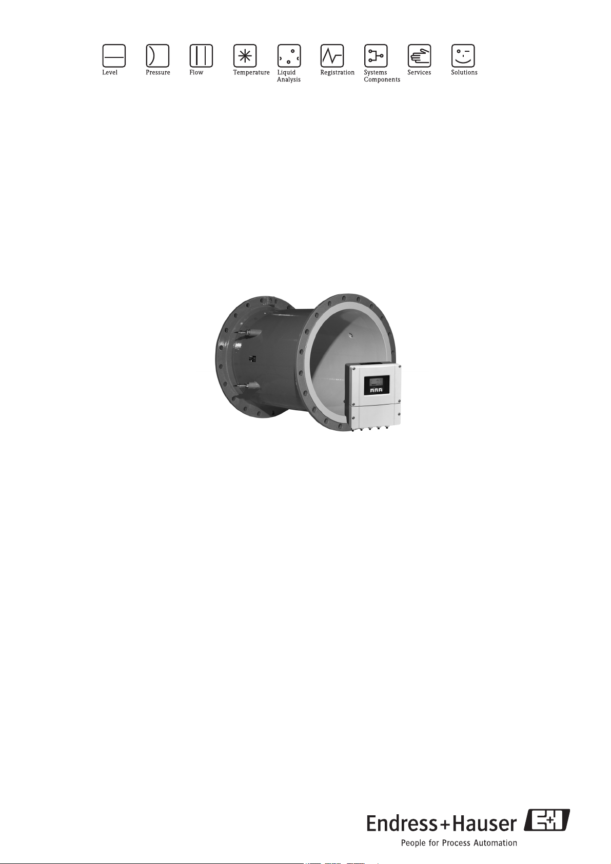
Proline Prosonic Flow 93C
Ultrasonic flow measuring system
Volume flow measurement for standard applications
with drinking water, wastewater and process water
Applications
The Prosonic Flow C sensor is perfectly suited for the
non-intrusive flow measurement of process water,
saltwater, drinking water and wastewater applications.
• Suitable for pipe diameters from DN 300 to 2000
(12 to 80")
• Available with drinking water approvals
• Interface for easy integration into all common
distributed control systems:
–HART
–PROFIBUS DP/PA
– FOUNDATION Fieldbus
Features and benefits
The Prosonic Flow C Inline is a dual path system and has
two pairs of insertion sensors. The flow measurement is
bidirectional and causes no pressure loss.
In addition, the system provides:
• High accuracy
• Traceable calibration
• Short inlet run requirements
• Removal and replacement of sensor elements without
process shutdown
• IP 68 rating
• Remote configuration using Endress+Hauser's
FieldCare Software
TI108D/06/en/07.10
71115163
Page 2

Table of contents
Proline Prosonic Flow 93C
Function and system design. . . . . . . . . . . . . . . . . . . . . 3
Measuring principle . . . . . . . . . . . . . . . . . . . . . . . . . . . . . . . . . . . 3
Measuring system . . . . . . . . . . . . . . . . . . . . . . . . . . . . . . . . . . . . . 3
Input . . . . . . . . . . . . . . . . . . . . . . . . . . . . . . . . . . . . . . 5
Measured variable . . . . . . . . . . . . . . . . . . . . . . . . . . . . . . . . . . . . 5
Measuring range . . . . . . . . . . . . . . . . . . . . . . . . . . . . . . . . . . . . . . 5
Operable flow range . . . . . . . . . . . . . . . . . . . . . . . . . . . . . . . . . . . 5
Input signal . . . . . . . . . . . . . . . . . . . . . . . . . . . . . . . . . . . . . . . . . 5
Output . . . . . . . . . . . . . . . . . . . . . . . . . . . . . . . . . . . . . 5
Output signal . . . . . . . . . . . . . . . . . . . . . . . . . . . . . . . . . . . . . . . . 5
Signal on alarm . . . . . . . . . . . . . . . . . . . . . . . . . . . . . . . . . . . . . . 6
Load . . . . . . . . . . . . . . . . . . . . . . . . . . . . . . . . . . . . . . . . . . . . . . 6
Switching output . . . . . . . . . . . . . . . . . . . . . . . . . . . . . . . . . . . . . 6
Low flow cutoff . . . . . . . . . . . . . . . . . . . . . . . . . . . . . . . . . . . . . . 6
Galvanic isolation . . . . . . . . . . . . . . . . . . . . . . . . . . . . . . . . . . . . . 6
Power supply . . . . . . . . . . . . . . . . . . . . . . . . . . . . . . . . 7
Electrical connection, measuring unit . . . . . . . . . . . . . . . . . . . . . . 7
Electrical connection, terminal assignment . . . . . . . . . . . . . . . . . . 8
Connecting the connecting cable . . . . . . . . . . . . . . . . . . . . . . . . . 8
Supply voltage . . . . . . . . . . . . . . . . . . . . . . . . . . . . . . . . . . . . . . . 9
Cable entry . . . . . . . . . . . . . . . . . . . . . . . . . . . . . . . . . . . . . . . . . 9
Connecting cable (sensor/transmitter) . . . . . . . . . . . . . . . . . . . . . 9
Power consumption . . . . . . . . . . . . . . . . . . . . . . . . . . . . . . . . . . . 9
Power supply failure . . . . . . . . . . . . . . . . . . . . . . . . . . . . . . . . . . . 9
Potential equalization . . . . . . . . . . . . . . . . . . . . . . . . . . . . . . . . . . 9
Human interface . . . . . . . . . . . . . . . . . . . . . . . . . . . . 18
Display elements . . . . . . . . . . . . . . . . . . . . . . . . . . . . . . . . . . . . 18
Operating elements . . . . . . . . . . . . . . . . . . . . . . . . . . . . . . . . . . 18
Language group . . . . . . . . . . . . . . . . . . . . . . . . . . . . . . . . . . . . . 18
Remote operation . . . . . . . . . . . . . . . . . . . . . . . . . . . . . . . . . . . . 18
Certificates and approvals . . . . . . . . . . . . . . . . . . . . . 19
CE mark . . . . . . . . . . . . . . . . . . . . . . . . . . . . . . . . . . . . . . . . . . 19
C-Tick mark . . . . . . . . . . . . . . . . . . . . . . . . . . . . . . . . . . . . . . . 19
PROFIBUS DP/PA certification . . . . . . . . . . . . . . . . . . . . . . . . . 19
FOUNDATION Fieldbus certification . . . . . . . . . . . . . . . . . . . . . 19
Other standards and guidelines . . . . . . . . . . . . . . . . . . . . . . . . . . 19
Ordering information. . . . . . . . . . . . . . . . . . . . . . . . . 19
Accessories . . . . . . . . . . . . . . . . . . . . . . . . . . . . . . . . 20
Device-specific accessories . . . . . . . . . . . . . . . . . . . . . . . . . . . . . 20
Measuring principle-specific accessories . . . . . . . . . . . . . . . . . . . 20
Communication-specific accessories . . . . . . . . . . . . . . . . . . . . . . 20
Service-specific accessories . . . . . . . . . . . . . . . . . . . . . . . . . . . . . 21
Documentation . . . . . . . . . . . . . . . . . . . . . . . . . . . . . 22
Registered trademarks . . . . . . . . . . . . . . . . . . . . . . . . 22
Performance characteristics. . . . . . . . . . . . . . . . . . . . 10
Reference operating conditions . . . . . . . . . . . . . . . . . . . . . . . . . . 10
Maximum measured error . . . . . . . . . . . . . . . . . . . . . . . . . . . . . 10
Repeatability . . . . . . . . . . . . . . . . . . . . . . . . . . . . . . . . . . . . . . . . 10
Operating conditions: installation . . . . . . . . . . . . . . . 11
Installation instructions . . . . . . . . . . . . . . . . . . . . . . . . . . . . . . . . 11
Inlet and outlet runs . . . . . . . . . . . . . . . . . . . . . . . . . . . . . . . . . . 12
Operating conditions: environment . . . . . . . . . . . . . . 13
Ambient temperature range . . . . . . . . . . . . . . . . . . . . . . . . . . . . 13
Storage temperature . . . . . . . . . . . . . . . . . . . . . . . . . . . . . . . . . . 13
Degree of protection . . . . . . . . . . . . . . . . . . . . . . . . . . . . . . . . . . 13
Shock and vibration resistance . . . . . . . . . . . . . . . . . . . . . . . . . . 13
Electromagnetic compatibility (EMC) . . . . . . . . . . . . . . . . . . . . . 13
Operating conditions: process . . . . . . . . . . . . . . . . . . 13
Medium temperature range . . . . . . . . . . . . . . . . . . . . . . . . . . . . 13
Medium pressure range (nominal pressure) . . . . . . . . . . . . . . . . . 13
Pressure loss . . . . . . . . . . . . . . . . . . . . . . . . . . . . . . . . . . . . . . . . 13
Mechanical construction . . . . . . . . . . . . . . . . . . . . . . 14
Design, dimensions . . . . . . . . . . . . . . . . . . . . . . . . . . . . . . . . . . 14
Weight . . . . . . . . . . . . . . . . . . . . . . . . . . . . . . . . . . . . . . . . . . . . 17
Materials . . . . . . . . . . . . . . . . . . . . . . . . . . . . . . . . . . . . . . . . . . 18
2 Endress+Hauser
Page 3

Proline Prosonic Flow 93C
b
a
Q
t
a
t
b
Function and system design
Measuring principle The measuring system operates on the principle of transit time difference. In this measurement method,
acoustic (ultrasonic) signals are transmitted between two sensors. The signals are sent in both directions,
i.e. the sensor in question works as both a sound transmitter and a sound receiver.
As the propagation velocity of the waves is less when the waves travel against the direction of flow than along
the direction of flow, a transit time difference occurs. This transit time difference is directly proportional to the
flow velocity.
Principle of the transit time difference measurement method
Q = v · A
aSensor
bSensor
Q Volume flow
v Flow velocity (v & t )
t Transit time difference (t = t
A Pipe cross-sectional area
– tb)
a
The measuring system calculates the volume flow of the fluid from the measured transit time difference and
the pipe cross-sectional area. In addition to measuring the transit time difference, the system simultaneously
measures the sound velocity of the fluid. This additional measured variable can be used to distinguish different
fluids or as a measure of product quality.
The measuring device can be configured onsite to suit the specific application using Quick Setup menus.
Measuring system The measuring system consists of one transmitter and four sensors.
The transmitter is used both to control the sensors and to prepare, process and evaluate the measuring signals,
and to convert the signals to a desired output variable.
The sensors work as sound transmitters and sound receivers.
A0005961
Endress+Hauser 3
Page 4
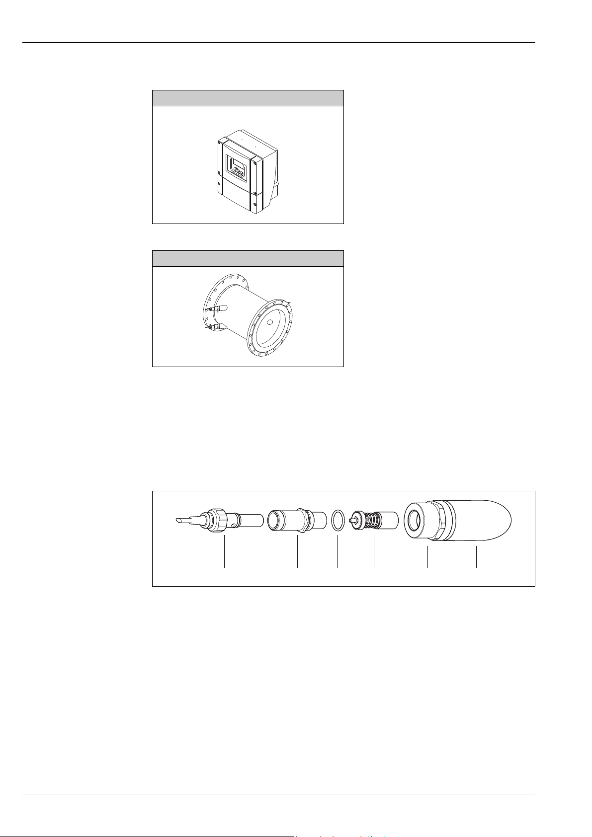
Transmitter
123456
Prosonic Flow 93 wall-mount housing
For mounting in non-hazardous zone
Sensor
Proline Prosonic Flow 93C
A0009629
Prosonic Flow C Inline
A0009681
The Prosonic Flow C Inline sensor consists of a measuring pipe which is integrated into the pipe system of the
application by means of process flanges.
The Prosonic Flow C Inline is a dual path system and has two pairs of insertion sensors.
The Prosonic Flow C Inline sensor is available with two different internal coatings depending on the
application:
• for drinking water: epoxy coating with approval for drinking water
• for wastewater: epoxy coating for wastewater
The active part of the sensor can be replaced without interrupting the process.
A0008753
1Sensor connector
2Sensor neck
3O-ring
4 Sensor element
5Sensor holer
6 Sensor support in measuring pipe Prosonic Flow C
4 Endress+Hauser
Page 5

Proline Prosonic Flow 93C
Input
Measured variable Flow velocity (transit time difference proportional to flow velocity)
Measuring range Typically v = 0 to 10 m/s (0 to 33 ft/s)
Operable flow range Over 150 : 1
Input signal Status input (auxiliary input)
U = 3 to 30 V DC, R
Configurable for:
totalizer(s) reset, measured-value suppression, error-message reset
= 5 k, galvanically isolated
i
Output
Output signal Current output
• Galvanically isolated
• Active/passive selectable
– Active: 0/4 to 20 mA, R
– Passive: 4 to 20 mA, max. 30 V DC, Ri 150
• Time constant selectable (0.01 to 100 s)
• Full scale value adjustable
• Temperature coefficient: typ. 0.005 % o.r./°C (o.r. = of reading)
• Resolution: 0.5 μA
Pulse/frequency output
• Galvanically isolated
• Active/passive selectable
– Active: 24 V DC, 25 mA (max. 250 mA during 20 ms), R
– Passive: open collector, 30 V DC, 250 mA
• Time constant selectable (0.05 to 100 s)
• Frequency output
– End frequency: 2 to 10000 Hz (f
– End frequency for EEx ia 2 to 5000 Hz
– On/off ratio 1:1, pulse width max. 10 s
• Pulse output
– Pulse value and pulse polarity selectable
– Max. pulse width adjustable (0.05 to 2000 ms)
– As of a frequency of 1 / (2 × pulse width), the on/off ratio is 1:1
< 700 (for HART: RL 250 )
L
= 12500 Hz)
max
> 100
L
PROFIBUS DP interface
• PROFIBUS DP in accordance with EN 50170 Volume 2
• Profile version 3.0
• Data transmission rate: 9.6 kBaud to 12 MBaud
• Automatic data transmission rate recognition
• Signal encoding = NRZ Code
• Function blocks: 8 × Analog input (AI), 3 × Totalizer
• Output data: volume flow channel 1 or channel 2, sound velocity channel 1 or channel 2,
flow velocity channel 1 or channel 2, average volume flow, average sound velocity, average flow velocity,
volume flow sum, volume flow difference, totalizer 1 to 3
• Input data: positive zero return (ON/OFF), zero point adjustment, measuring mode, totalizer control
• Bus address adjustable via miniature switches or local display (optional) at the measuring device
Endress+Hauser 5
Page 6

Proline Prosonic Flow 93C
PROFIBUS PA interface
• PROFIBUS PA in accordance with EN 50170 Volume 2, IEC 61158-2 (MBP)
• Galvanically isolated
• Data transmission rate, supported baudrate: 31.25 kBit/s
• Current consumption = 11 mA
• Error current FDE (fault disconnection electronic) = 0 mA
• Signal encoding = Manchester II
• Function blocks: 8 × Analog Input (AI), 3 × Totalizer
• Output data: volume flow channel 1 or channel 2, sound velocity channel 1 or channel 2,
flow velocity channel 1 or channel 2, average volume flow, average sound velocity, average flow velocity,
volume flow sum, volume flow difference, totalizer 1 to 3
• Input data: positive zero return (ON/OFF), operation control, totalizer control, zero point adjustment
control, display value
• Bus address can be set via DIP switch on device
FOUNDATION Fieldbus interface
• FOUNDATION Fieldbus H1, IEC 61158-2
• Galvanically isolated
• Data transmission rate, supported baudrate: 31.25 kBit/s
• Current consumption = 12 mA
• Error current FDE (fault disconnection electronic) = 0 mA
• Signal encoding = Manchester II
• Function blocks: 8 × Analog Input (AI), 1 × Discrete Output, 1 × PID
• Output data: volume flow channel 1 or channel 2, sound velocity channel 1 or channel 2,
flow velocity channel 1 or channel 2, signal strength channel 1 or 2, average volume flow,
average sound velocity, average flow velocity, volume flow sum, difference, volume flow, totalizer 1 to 3
• Input data: positive zero return (ON/OFF), reset totalizer, zero point adjustment control
• Link master function (LAS) is supported
Signal on alarm • Current output failsafe mode selectable
• Pulse/frequency output failsafe mode selectable
• Relay output "deenergized" in the event of a fault or if the power supply fails
Load See "Output signal"
Switching output Relay output
• NC or NO contact available
Factory setting: relay 1 = NO contact, relay 2 = NC contact
• Max. 30 V / 0.5 A AC; 60 V / 0.1 A DC
• Galvanically isolated
• Configurable for: error messages, flow direction, limit values
Low flow cutoff Switch points for low flow are selectable
Galvanic isolation All circuits for inputs, outputs, and power supply are galvanically isolated from each other.
6 Endress+Hauser
Page 7
Proline Prosonic Flow 93C
HART*
PROFIBUS DP**
27
25
23
21
2
1
26
24
22
20
L1 (L+)
N (L-)
–
–
–
+
+
+
PROFIBUS PA*
FOUNDATION Fieldbus*
PA(–)/FF(–)
27
25
23
21
2
1
26
24
22
20
L1 (L+)
N (L-)
–
–
–
+
+
+
A (RxD/TxD-N)
B (RxD/TxD-P)
PA(+)/FF(+)
d
c
e
b
–27
–25
–23
–21
+26
+24
+22
+20
N (L-) 2
L1 (L+)1
25
23
21
2
1
24
22
20
L1 (L+)
N (L-)
–
–
–
+
+
+
27
26
A (RxD/TxD-N)
B (RxD/TxD-P)
d
c
e
b
d
c
e
b
g
d
c
e
b
g
PROFIBUS DP*
f f
f f
a
A
(d)
b
d/(g)
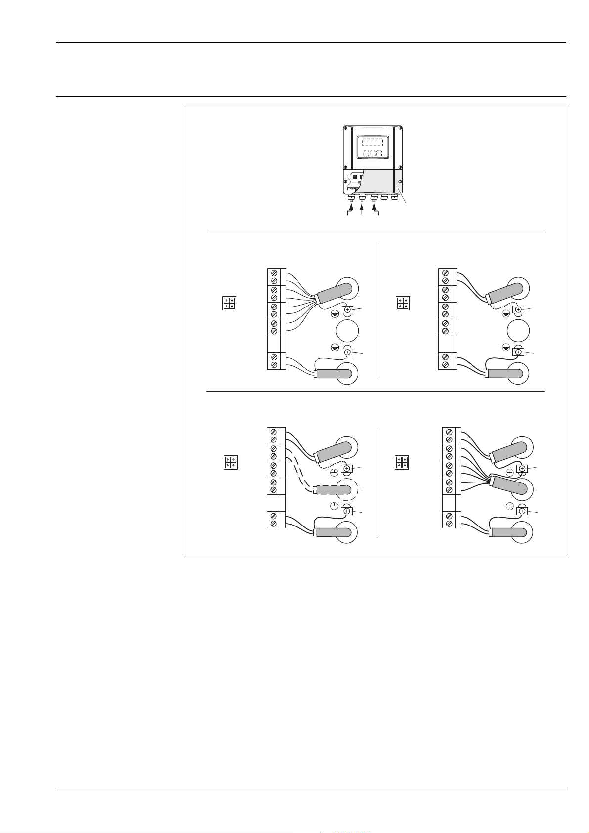
Electrical connection, measuring unit
Power supply
Connecting the transmitter, cable cross-section max. 2.5 mm2 (14 AWG)
A View A (wall-mount housing)
*) fixed communication boards
**) flexible communication boards
a Connection compartment cover
b Cable for power supply: 85 to 260 V AC / 20 to 55 V AC / 16 to 62 V DC
c Ground terminal for protective conductor
d Signal cable: see terminal assignment ä 8
- Terminal No. 1: L1 for AC, L+ for DC
- Terminal No. 2: N for AC, L– for DC
Fieldbus cable:
- Terminal No. 26: DP (B) / PA (+) / FF (+) with polarity protection
- Terminal No. 27: DP (A) / PA (–) / FF (–) with polarity protection
e Ground terminal for signal cable shield / Fieldbus cable
f Service adapter for connecting service interface FXA193 (Fieldcheck, FieldCare)
g Signal cable: see terminal assignment ä 8
Cable for external termination (only for PROFIBUS DP with fixed assignment communication board):
- Terminal No. 24: +5 V
- Terminal No. 25: DGNDA
A0013924
Endress+Hauser 7
Page 8
Proline Prosonic Flow 93C
A
1
A
32
4
Electrical connection, terminal assignment
The inputs and outputs on the communication board can be either permanently assigned or variable, depending
on the version ordered (see table). Replacements for modules which are defective or which have to be replaced
can be ordered as accessories.
Order variant Terminal No. (inputs/outputs)
20 (+) / 21 (–) 22 (+) / 23 (–) 24 (+) / 25 (–) 26 (+) / 27 (–)
Fixed communication boards (fixed assignment)
93***-***********A – – Frequency output Current output HART
93***-***********B Relay output 2 Relay output 1 Frequency output Current output HART
93***-***********H – – – PROFIBUS PA
93***-***********J – – – PROFIBUS DP
93***-***********K – – – FOUNDATION Fieldbus
Flexible communication boards
93***-***********C Relay output 2 Relay output 1 Frequency output Current output HART
93***-***********D Status input Relay output Frequency output Current output HART
93***-***********L Status input Relay output 2 Relay output 1 Current output HART
93***-***********M Status input Frequency output Frequency output Current output HART
93***-***********P Current output Frequency output Status input PROFIBUS DP
93***-***********V Relay output 2 Relay output 1 Status input PROFIBUS DP
93***-***********W Relay output Current output Current output Current output HART
93***-***********2 Relay output Current output Frequency output Current output HART
Ground terminal ä 7
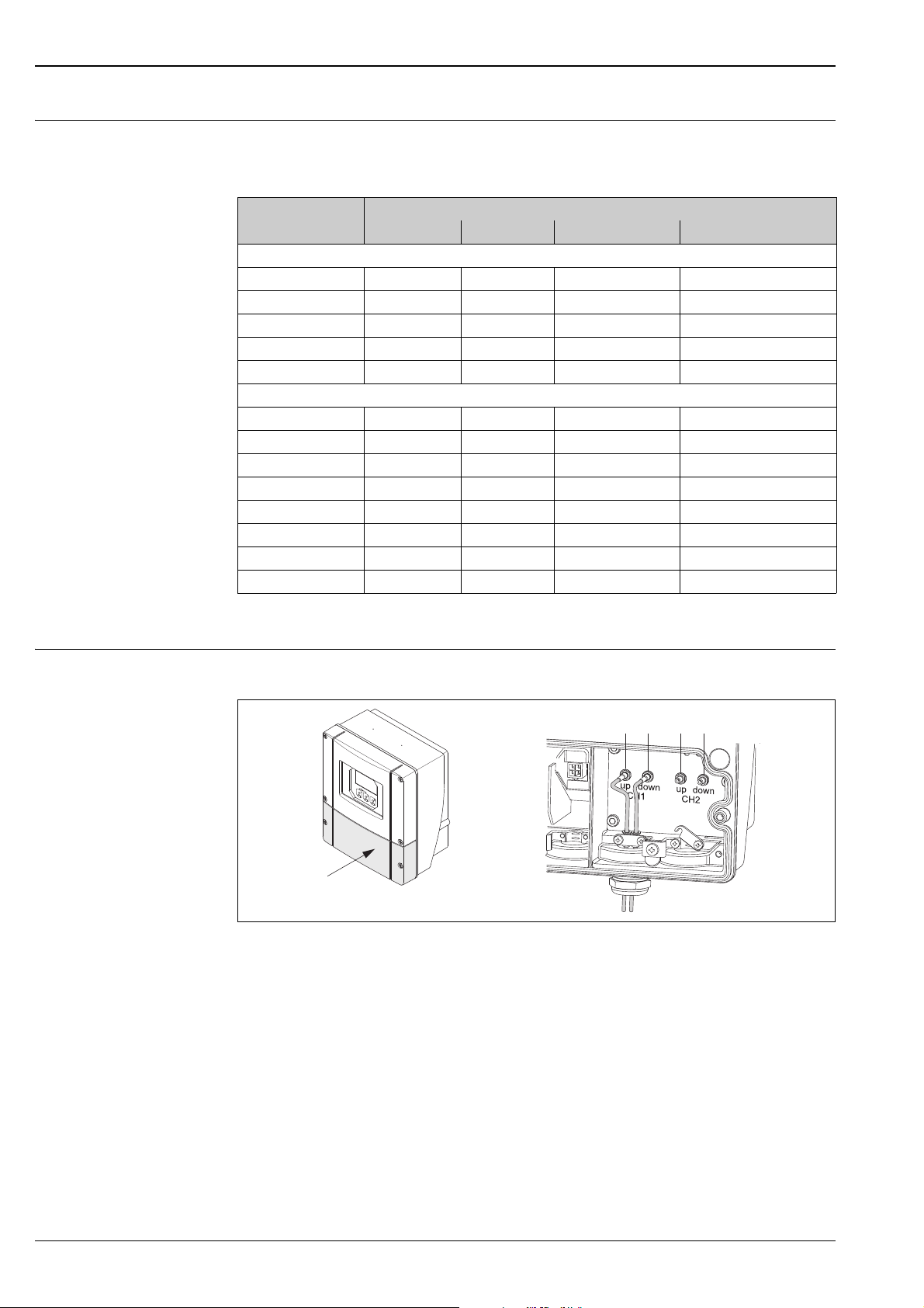
Connecting the connecting cable
Connecting the wall-mount housing
A0011390
Connecting the connecting cable, wall-mount housing
1Channel 1 upstream
2Channel 1 downstream
3 Channel 2 upstream (only available when ordered)
4 Channel 2 downstream (only available when ordered)
8 Endress+Hauser
Page 9

Proline Prosonic Flow 93C
Supply voltage Transmitter
HART
• 85 to 260 V AC, 45 to 65 Hz
• 20 to 55 V AC, 45 to 65 Hz
• 16 to 62 V DC
PROFIBUS DP/PA
• 9 to 32 V DC
FOUNDATION Fieldbus
• 9 to 32 V DC
Sensor
Powered by the transmitter
Cable entry Power supply and signal cables (inputs/outputs)
• Cable gland M20 × 1.5
– Cable gland for cables 8 to 12 mm (0.3 to 0.5")
– Cable gland for cables 6 to 12 mm (0.2 to 0.5")
• Thread for cable entry ½" NPT, G ½"
Connecting cable (sensor/transmitter)
!
Connecting cable (sensor/transmitter)
Cable gland for one connecting cable per cable entry, 1 × 8 mm (0.31")
• Cable gland M20 × 1.5
• Thread for cable entry ½" NPT, G ½"
Cable gland for two connecting cables per cable entry, 2 × 4 mm (0.16")
• Cable gland M20 × 1.5
• Thread for cable entry ½" NPT, G ½"
A0008152
Cable gland for two connecting cables per cable entry
Only use the connecting cables supplied by Endress+Hauser.
Different versions of the connecting cables are available ä 20.
• Cable material made of PVC (standard)
• Cable length: 5 to 30 m (16.4 to 98.4 ft)
Note!
To ensure correct measuring results, route the connecting cable well clear of electrical machines and switching
elements.
Power consumption AC: < 18 VA (incl. sensor)
DC: < 10 W (incl. sensor)
Switch-on current
• max. 13.5 A (< 50 ms) at 24 V DC
• max. 3 A (< 5 ms) at 260 V AC
Power supply failure Lasting min. 1 power cycle
HistoROM/T-DAT save measuring system data if the power supply fails
Potential equalization For potential equalization, no special measures are necessary.
Endress+Hauser 9
Page 10

Performance characteristics
Proline Prosonic Flow 93C
Reference operating conditions
Maximum measured error For flow velocities of > 0.3m/s (1 ft/s) and a Reynolds number of > 10000, the system accuracy is:
!
Repeatability
• Fluid temperature: +20 to +30 °C
• Ambient temperature: +22 °C ± 2 K
• Warm-up period: 30 minutes
• Sensors and transmitter are grounded.
• The measuring sensors are correctly installed.
Nominal diameter Guaranteed error limits of the device Report
DN 300 to 2000 (12 to 80") ±0.5 % o.r. ± 3 mm/s Factory measurement report
o.r. = of reading
Note!
The Prosonic Flow 93 C Inline sensor is also available without factory flow calibration.
The error limits without calibration are ±1.5 % o.r. ± 3 mm/s
±0.3 % for flow velocities > 0.3 m/s (1 ft/s)
10 Endress+Hauser
Page 11

Proline Prosonic Flow 93C
A
B
Operating conditions: installation
Installation instructions Mounting location
Correct flow measurement is possible only if the pipe is full. It is preferable to install the sensors in a riser.
!
Note!
Entrained air or gas bubbles in the measuring tube can result in an increase in measuring errors.
For this reason, avoid the following mounting locations:
• Highest point of a pipeline. Risk of air accumulating.
• Directly upstream of a free pipe outlet in a vertical pipe. Risk of partial pipe filling.
A0014011
Orientation
Vertical
Recommended orientation with upward direction of flow (View A). With this orientation, entrained solids will
sink and gases will rise away from the sensor when the fluid is stagnant. The piping can be completely drained
and protected against solids buildup.
Horizontal
In the recommended installation range in a horizontal installation position (View B), gas and air collections at
the pipe cover and problematic deposits at the bottom of the pipe have a smaller influence on measurement.
A0014015
A Recommended orientation with upward direction of flow
B Recommended installation range with horizontal orientation
Endress+Hauser 11
Page 12

Proline Prosonic Flow 93C
> 10 m (33 ft)
³ 10xDN
³ 20xDN
³ 15xDN
³ 10xDN
³ 3xDN
1
2
3
Vibrations
Secure the piping and the Prosonic Flow C Inline sensor if vibration is severe.
Information on resistance to vibration and shock ä 13.
A0006103
Foundations, supports
For all nominal diameter mount the sensor on a foundation of adequate load-beating strength. The foundation/
supports must work on the pipe flanges and not on the measuring pipe flanges of Prosonic Flow C.
A0008751
Inlet and outlet runs If possible, install the sensor well clear of fittings such as valves, T-pieces, elbows, etc. Compliance with the
following inlet and outlet runs is required in order to ensure measuring accuracy.
Inlet und outlet runs
1 Valve (2/3 open)
2Pump
3 Two pipe bends in different directions
12 Endress+Hauser
A0014016
Page 13

Proline Prosonic Flow 93C
Operating conditions: environment
Ambient temperature range Transmitter
–20 to +60 °C (–4 to +140 °F)
Sensor Prosonic Flow 93C
• –20 to +80 °C (–4 to +176 °F)
Connecting cable (sensor/transmitter)
• Standard (PVC): –20 to +70 °C (–4 to +158 °F)
!
Storage temperature The storage temperature corresponds to the ambient temperature range.
Degree of protection Transmitter
Note!
• Mount the transmitter in a shady location and avoid direct sunlight, particularly in warm climatic regions.
IP 67 (NEMA 4X)
Sensor
IP 68 (NEMA 6P)
Shock and vibration resistance According to IEC 68-2-6
Electromagnetic compatibility (EMC)
Electromagnetic compatibility (EMC requirements) according to IEC/EN 61326 "Emission to class A
requirements" and NAMUR Recommendation NE 21/43.
Operating conditions: process
Medium temperature range Prosonic Flow 93C sensor
–10 to +80 °C (+14 to +176 °F)
• Drinking Water Approval: 0 to +60 °C (+32 to +140 °F)
Medium pressure range (nominal pressure)
Pressure loss There is no pressure loss.
The maximum nominal pressure is PN 16 (16 bar / 232 psi).
Endress+Hauser 13
Page 14

Mechanical construction
Esc
E
-
+
DC
B
A
F
E
G
K
J
Q
NL
O
R
H J
M
PP
SS
T
Design, dimensions Transmitter wall-mount housing
Proline Prosonic Flow 93C
Dimensions (SI units)
A B C D E F G H J K
215 250 90.5 159.5 135 90 45 > 50 81 53
L M N O P Q R S T
95 53 102 81.5 11.5 192 8 × M5 20 2 × 6.5
1)
Securing screw for wall mounting: M6 (screw head max. 10.5 mm)
All dimensions in [mm]
Dimensions (US units)
A B C D E F G H J K
8.46 9.84 3.56 6.27 5.31 3.54 1.77 > 1.97 3.18 2.08
L M N O P Q R S T
3.74 2.08 4.01 3.20 0.45 7.55 8 × M5 0.79 2 × 0.26
1)
Securing screw for wall mounting: M6 (screw head max. 0.41")
All dimensions in [inch]
A0001150
1)
1)
14 Endress+Hauser
Page 15

Proline Prosonic Flow 93C
245 (9.65)
~110(~4.33)
210 (8.27)
+0.5 (+0.019)
–0.5 (–0.019)
+0.5 (+0.019)
–0.5 (–0.019)
mm (inch)
Ø 20…70
(Ø 0.79…2.75)
~ ~ 6.1)155 (
mm (inch)
!
Panel mounting
Note!
To aid mounting, mounting kits are available as accessories ä 20.
!
Pipe mounting
Note!
To aid mounting, mounting kits are available as accessories ä 20.
A0001131
A0001132
Endress+Hauser 15
Page 16

Prosonic Flow C Inline
K
C
B
L
A
Calibrated measuring pipe with flowrate measuring sensors C
Proline Prosonic Flow 93C
A0009677
DN A B C L K
EN (DIN)
PN 6
[mm]
– 300 – – 520 317.5 165.1 500 445
– – 300 – 517 313.9 163.2 500 460
– – – 12" 517 313.9 163.2 500 482.6
– 350 – – 548 350 182 550 505
– – 350 – 546 348 181 550 520
– – – 14" 544 346 179.9 550 533.4
– 400 – – 590 400 208 600 565
– – 400 – 589 398 207 600 580
– – – 16" 587 396 205.9 600 596.9
– – – 18" 629 445 231.4 650 635
– 500 – – 676 500 260 650 670
– – 500 – 674 498 259 650 715
– – – 20" 672 496 257.9 650 699
– 600 – – 763 602 313 780 780
– – 600 – 760 598 311 780 840
– – – 24" 756 594 308.9 780 813
– 700 – – 848 701 364.5 910 895
– – 700 – 842 695 361.4 910 910
– – – 28" 846 699 363.5 910 927.1
– – – 30" 889 750 390 975 984.25
– 800 – – 935 803 417.6 1040 1015
– – 800 – 930 797 414.4 1040 1025
– – – 32" 933 801 416.5 1040 1060.45
– 900 – – 1019 902 469 1170 1115
– – 900 – 1012 894 464.9 1170 1125
– – – 36" 1016 898 467 1170 1168.4
– 1000 – – 1106 1004 522.1 1300 1230
– – 1000 – 1100 996 517.9 1300 1255
– – – 40" 1103 1000 520 1300 1289.05
– – – 42" 1147 1051 546.5 1365 1346.2
EN (DIN)
PN 10
[mm]
EN (DIN)
PN 16
[mm]
ANSI/AWWA
[inch]
[mm] [mm] [mm] [mm] [mm]
16 Endress+Hauser
Page 17

Proline Prosonic Flow 93C
DN A B C L K
EN (DIN)
PN 6
[mm]
1200 – – – 1282 1210 629.2 1560 1405
– 1200 – – 1277 1204 626.1 1560 1455
– – 1200 – 1270 1196 621.9 1560 1485
– – – 48" 1274 1200 624 1560 1511.3
– – – 54" 1399 1347 700.4 1755 1682.75
1400 – – – 1453 1410 733.2 1820 1630
– 1400 – – 1448 1404 730.1 1820 1675
– – 1400 – 1441 1396 725.9 1820 1685
– – – 60" 1530 1500 780 1950 1854.2
1600 – – – 1622 1608 836.2 2080 1830
– 1600 – – 1615 1600 832 2080 1915
– – 1600 – 1607 1590 826.8 2080 1930
– – – 66" 1655 1646 855.9 2145 2032
1800 – – – 1793 1808 940.2 2340 2045
– 1800 – – 1786 1800 936 2340 2115
– – 1800 – 1776 1788 929.8 2340 2130
– – – 72" 1778 1790 930.8 2340 2197.1
2000 – – – 1961 2004 1042.1 2600 2265
– 2000 – – 1954 1996 1037.9 2600 2325
– – 2000 – 1943 1984 1031.7 2600 2345
– – – 80" 1949 1990 1034.8 2600 2362.2
The fitting length (L) is always the same per nominal diameter, regardless of the pressure rating selected.
EN (DIN)
PN 10
[mm]
EN (DIN)
PN 16
[mm]
ANSI/AWWA
[inch]
[mm] [mm] [mm] [mm] [mm]
Weight Transmitter
• Wall mount housing: 6.0 kg (13.2 lbs)
Measuring pipe incl. sensors
Nominal diameter Measuring pipe incl. sensors in [kg]*
[mm] [inch] EN (DIN), PN 6 EN (DIN), PN 10 EN (DIN), PN 16 ANSI, Class 150 AWWA, Class D
300 12" – 41.8 59.6 77.2 –
350 14" – 54.7 70.1 111.2 –
400 16" – 66.4 90.3 139.6 –
–18" – – – 162.7 –
500 20" – 96.8 145.9 197.8 –
600 24" – 120.4 196.6 287.9 –
700 28" – 183.6 251.3 – 229.9
– 30" – – – – 265.1
800 32" – 245.0 327.0 – 323.9
900 36" – 313.7 456.3 – 455.6
1000 40" – 379.0 587.3 – 552.6
– 42" – – – – 626.1
1200 48" 434.6 678.6 941.7 – 894.7
– 54" – – – – 1280.2
1400 – 569.2 907.6 1267.6 – –
– 60" – – – – 1584.5
1600 – 818.7 1381.4 2012.0 – –
– 66" – – – – 2268.0
1800 72" 993.5 1726.7 2608.2 – 2707.0
2000 80" 1508.2 2393.6 3601.3 – 3073.9
* Weight data valid for standard pressure ratings and without packaging material
Prosonic Flow C (Inline)
Endress+Hauser 17
Page 18

Materials Transmitter Prosonic Flow 93
• Wall-mounted housing: powder-coated die-cast aluminum
Sensor Prosonic Flow C Inline
• Sensor housing: 1.4404/DN 17440 (316L/AISI)
• Weld-in parts: 1.4404/DN 17440 (316L/AISI)
• Measuring pipe: ST 37.2 (carbon steel)
Standard sensor cable
• Cable sheath: PVC
• Cable connector: nickled brass 2.0401
Human interface
Display elements • Liquid crystal display: illuminated, four lines each with 16 characters
• Custom configuration for presenting different measured values and status variables
• 3 totalizers
Proline Prosonic Flow 93C
Operating elements • Local operation with three optical keys
• Application specific Quick Setup menus for straightforward commissioning
Language group Language groups available for operation in different countries:
• Western Europe and America (WEA):
English, German, Spanish, Italian, French, Dutch and Portuguese
• Eastern Europe/Scandinavia (EES):
English, Russian, Polish, Norwegian, Finnish, Swedish and Czech
• South and Eastern Asia (SEA):
English, Japanese, Indonesian
• China (CN):
English, Chinese
You can change the language group via the FieldCare operating program.
Remote operation Operation via HART, PROFIBUS DP/PA, FOUNDATION Fieldbus
18 Endress+Hauser
Page 19

Proline Prosonic Flow 93C
Certificates and approvals
CE mark The measuring system is in conformity with the statutory requirements of the EC Directives.
Endress+Hauser confirms successful testing of the device by affixing to it the CE mark.
C-Tick mark The measuring system is in conformity with the EMC requirements of the "Australian Communications and
Media Authority" (ACMA).
PROFIBUS DP/PA certification
FOUNDATION Fieldbus certification
Other standards and guidelines
The flowmeter has successfully passed all the test procedures carried out and is certified and registered by the
PNO (PROFIBUS/DP User Organization). The device thus meets all the requirements of the following
specifications:
• Certified to PROFIBUS DP/PA, profile version 3.0 (device certification number: on request)
• The device can also be operated with certified devices of other manufacturers (interoperability)
The flowmeter has successfully passed all the test procedures carried out and is certified and registered by the
Fieldbus Foundation. The device thus meets all the requirements of the following specifications:
• Certified to FOUNDATION Fieldbus Specification
• The device meets all the specifications of the FOUNDATION Fieldbus H1.
• Interoperability Test Kit (ITK), revision status 5.01 (device certification number: on request)
• The device can also be operated with certified devices of other manufacturers
• Physical Layer Conformance Test of the Fieldbus Foundation
• EN 60529
Degrees of protection provided by enclosures (IP code)
• EN 61010-1
Safety requirements for electrical equipment for measurement, control and laboratory use
• IEC/EN 61326
"Emission in accordance with Class A requirements".
Electromagnetic compatibility (EMC requirements).
• ANSI/ISA-S82.01
Safety Standard for Electrical and Electronic Test, Measuring, Controlling and Related
Equipment - General Requirements. Pollution Degree 2, Installation Category II.
• CAN/CSA-C22.2 No. 1010.1-92
Safety Requirements for Electrical Equipment for Measurement and Control and Laboratory Use.
Pollution degree 2, Installation Category II
• NAMUR NE 21
Electromagnetic compatibility (EMC) of industrial process and laboratory control equipment.
• NAMUR NE 43
Standardization of the signal level for the breakdown information of digital transmitters with analog output
signal.
• NAMUR NE 53
Software of field devices and signal-processing devices with digital electronics.
Ordering information
The Endress+Hauser sales and service organization can provide detailed ordering information and information
on the order codes on request.
Endress+Hauser 19
Page 20

Proline Prosonic Flow 93C
Accessories
Various accessories, which can be ordered separately from Endress+Hauser, are available for the transmitter
and the sensor. The Endress+Hauser service organization can provide detailed information on the order codes
on request.
Device-specific accessories
Measuring principle-specific
accessor
ies
Accessory Description Order code
Wall-mount housing,
transmitter
Prosonic Flow 93
Conversion kit,
inputs/outputs
Accessory Description Order code
Mounting kit for
aluminum field housing
93C Flow sensor set Type C Sensors
Conduit adapter for
connecting cable
Connecting cable 5 m sensor cable, PVC, –20 to +70 °C (–4 to +158 °F)
Transmitter for replacement or for stock. Use the order code to
define the following specifications:
•Approvals
• Degree of protection/version
•Cable entry
• Display / power supply / operation
•Software
• Outputs / inputs
Conversion kit with appropriate plug-in point modules for
converting the current input/output configuration to a new
version.
Mounting kit for wall-mount housing.
Suitable for:
• Wall mounting
• Pipe mounting
• Panel mounting
• (DN 300 to 2000 (11.8 to 78.7")
• –10 to 60 °C (14 to 140 °F)
• NEMA IP68
Prosonic Flow 93C (DN 50 to 4000 / 2 to 160")
• Conduit adapter incl. cable entry M20 × 1.5
• Conduit adapter incl. cable entry ½" NPT
• Conduit adapter incl. cable entry G ½"
10 m sensor cable, PVC, –20 to +70 °C (–4 to +158 °F)
15 m sensor cable, PVC, –20 to +70 °C (–4 to +158 °F)
30 m sensor cable, PVC, –20 to +70 °C (–4 to +158 °F)
Two-channel version:
93XXX - XX2XX********
DK9UI - **
DK9WM - A
DK9WS - L*
DK9CB - BD1
DK9CB - BD2
DK9CB - BD3
DK9SS - BDA
DK9SS - BDB
DK9SS - BDC
DK9SS - BDD
20 Endress+Hauser
Page 21

Proline Prosonic Flow 93C
Communication-specific accessories
Accessory Description Order code
HART handheld terminal
DXR375
Fieldgate FXA320 Gateway for remote interrogation of HART sensors and actuators
Fieldgate FXA520 Gateway for remote interrogation of HART sensors and actuators
Handheld terminal for remote configuration and for obtaining
measured values via the HART current output
(4 to 20 mA) and FOUNDATION Fieldbus.
Contact your Endress+Hauser representative for more
information.
via Web browser:
• 2-channel analog input (4 to 20 mA)
• 4 binary inputs with event counter function and frequency
measurement
• Communication via modem, Ethernet or GSM
• Visualization via Internet/Intranet in the Web browser and/or
WAP cellular phone
• Limit value monitoring with alarm signaling via e-mail or SMS
• Synchronized time stamping of all measured values.
via Web browser:
• Web server for remote monitoring of up to 30 measuring points
• Intrinsically safe version [EEx ia]IIC for applications in
hazardous areas
• Communication via modem, Ethernet or GSM
• Visualization via Internet/Intranet in the Web browser and/or
WAP cellular phone
• Limit value monitoring with alarm signaling via e-mail or SMS
• Synchronized time stamping of all measured values
• Remote diagnosis and remote configuration of
connected HART devices
DXR375 - *******
FXA320 - *****
FXA520 - ****
Service-specific accessories
Accessory Description Order code
Applicator Software for selecting and planning flowmeters.
The Applicator can be downloaded from the Internet or ordered
on CD-ROM for installation on a local PC.
Contact your Endress+Hauser representative for more
information.
Fieldcheck Tester/simulator for testing flowmeters in the field.
When used in conjunction with the "FieldCare" software package,
test results can be imported into a database, printed out and used
for official certification.
Contact your Endress+Hauser representative for more
information.
FieldCare FieldCare is Endress+Hauser's FDT-based plant asset management
tool. It can configure all intelligent field units in your system and
helps you manage them.
By using the status information, it is also a simple but effective way
of checking their status and condition.
FXA193 Service interface from the measuring device to the PC for
operation via FieldCare.
Communication cable Communication cable for connecting the Prosonic Flow 93C
transmitter to the FXA193 service interface.
DXA80 - *
50098801
See the product page on
the Endress+Hauser Web
site:
www.endress.com
FXA193 – *
DK9ZT – A
Endress+Hauser 21
Page 22

Proline Prosonic Flow 93C
Documentation
• Flow measurement (FA005D)
• Operating Instructions for Prosonic Flow 93 (BA070D and BA071D)
• Operating Instructions for Prosonic Flow 93 PROFIBUS DP/PA (BA076D and BA077D)
• Operating Instructions for Prosonic Flow 93 FOUNDATION Fieldbus (BA078D and BA079D)
• Supplementary documentation on Ex-ratings: ATEX, FM, CSA, IECEx, NEPSI
Registered trademarks
HART®
Registered trademark of HART Communication Foundation, Austin, USA
PROFIBUS
Registered trademark of the PROFIBUS User Organization, Karlsruhe, Germany
FOUNDATION™ Fieldbus
Registered trademark of the Fieldbus FOUNDATION, Austin, USA
HistoROM™, T-DAT™, F-CHIP
Registered or registration-pending trademarks of Endress+Hauser Flowtec AG, Reinach, CH
®
®
, FieldCare®, Fieldcheck
®
22 Endress+Hauser
Page 23

Proline Prosonic Flow 93C
Endress+Hauser 23
Page 24

Instruments International
Endress+Hauser
Instruments International AG
Kaegenstrasse 2
4153 Reinach
Switzerland
Tel. +41 61 715 81 00
Fax +41 61 715 25 00
www.endress.com
info@ii.endress.com
TI108D/06/en/07.10
71115163
FM+SGML6.0 ProMoDo
 Loading...