

Page 1
Operating Instructions
Esc
Esc
Proline Prosonic Flow 92F HART
Ultrasonic Flow Measuring System
6
BA00121D/06/EN/13.10
71124139
Valid as of version
V1.01.XX (device software)
Page 2

Page 3

Proline Prosonic Flow 92F Table of contents
Table of contents
1 Safety instructions . . . . . . . . . . . . . . . . 5
1.1 Designated use . . . . . . . . . . . . . . . . . . . . . . . . . . . . 5
1.2 Installation, commissioning and operation . . . . . . . . 5
1.3 Operational safety . . . . . . . . . . . . . . . . . . . . . . . . . . 5
1.4 Return . . . . . . . . . . . . . . . . . . . . . . . . . . . . . . . . . . . 6
1.5 Notes on safety conventions and icons . . . . . . . . . . . 6
2 Identification . . . . . . . . . . . . . . . . . . . . 7
2.1 Device designation . . . . . . . . . . . . . . . . . . . . . . . . . 7
2.1.1 Nameplate of the transmitter . . . . . . . . . . . . 7
2.1.2 Nameplate of the sensor . . . . . . . . . . . . . . . 8
2.1.3 Nameplate for connections . . . . . . . . . . . . . 8
2.2 Certificates and approvals . . . . . . . . . . . . . . . . . . . . 9
2.3 Registered trademarks . . . . . . . . . . . . . . . . . . . . . . . 9
3 Installation . . . . . . . . . . . . . . . . . . . . . 10
3.1 Incoming acceptance, transport, storage . . . . . . . . . 10
3.1.1 Incoming acceptance . . . . . . . . . . . . . . . . . 10
3.1.2 Transport . . . . . . . . . . . . . . . . . . . . . . . . . 10
3.1.3 Storage . . . . . . . . . . . . . . . . . . . . . . . . . . . 10
3.2 Installation conditions . . . . . . . . . . . . . . . . . . . . . . 11
3.2.1 Dimensions . . . . . . . . . . . . . . . . . . . . . . . . 11
3.2.2 Mounting location . . . . . . . . . . . . . . . . . . . 11
3.2.3 Orientation . . . . . . . . . . . . . . . . . . . . . . . . 12
3.2.4 Heating . . . . . . . . . . . . . . . . . . . . . . . . . . . 12
3.2.5 Thermal insulation . . . . . . . . . . . . . . . . . . 13
3.2.6 Inlet and outlet run . . . . . . . . . . . . . . . . . . 13
3.2.7 Limiting flow . . . . . . . . . . . . . . . . . . . . . . . 13
3.3 Installation instructions . . . . . . . . . . . . . . . . . . . . . 14
3.3.1 Mounting the sensor . . . . . . . . . . . . . . . . . 14
3.3.2 Turning the transmitter housing . . . . . . . . 14
3.3.3 Turning the local display . . . . . . . . . . . . . . 14
3.3.4 Mounting the remote version . . . . . . . . . . 15
3.4 Post-installation check . . . . . . . . . . . . . . . . . . . . . . 15
4 Wiring . . . . . . . . . . . . . . . . . . . . . . . . 16
4.1 Connecting the remote version . . . . . . . . . . . . . . . 16
4.1.1 Connecting cable for sensor/transmitter . . 16
4.1.2 Cable specification for connecting cable . . . 16
4.2 Connecting the measuring unit . . . . . . . . . . . . . . . 17
4.2.1 Connecting the transmitter . . . . . . . . . . . . 17
4.2.2 Terminal assignment . . . . . . . . . . . . . . . . . 19
4.2.3 HART connection . . . . . . . . . . . . . . . . . . . 20
4.3 Degree of protection . . . . . . . . . . . . . . . . . . . . . . . 21
4.4 Post-connection check . . . . . . . . . . . . . . . . . . . . . . 22
5 Operation . . . . . . . . . . . . . . . . . . . . . . 23
5.1 Display and operating elements . . . . . . . . . . . . . . . 23
5.2 Operation via the function matrix . . . . . . . . . . . . . 24
5.2.1 General notes . . . . . . . . . . . . . . . . . . . . . . 25
5.2.2 Enabling the programming mode . . . . . . . . 25
5.2.3 Disabling the programming mode . . . . . . . 25
5.3 Communication . . . . . . . . . . . . . . . . . . . . . . . . . . 26
5.3.1 Operating options . . . . . . . . . . . . . . . . . . . 27
5.3.2 Current device description files . . . . . . . . . 28
5.3.3 Device variables and process variables . . . . 29
5.3.4 Universal/common practice HART commands . . 30
5.3.5 Device status/diagnosis code messages . . . . 35
5.3.6 Switching HART write protection on/off . . 37
6 Commissioning . . . . . . . . . . . . . . . . . . 38
6.1 Function check . . . . . . . . . . . . . . . . . . . . . . . . . . . 38
6.2 Switching on the measuring device . . . . . . . . . . . . 38
6.3 Quick Setup . . . . . . . . . . . . . . . . . . . . . . . . . . . . . . 39
6.3.1 "Commissioning" Quick Setup . . . . . . . . . . 39
6.3.2 Data backup with the T–DAT SAVE/LOAD
function . . . . . . . . . . . . . . . . . . . . . . . . . . . 41
6.4 Adjust . . . . . . . . . . . . . . . . . . . . . . . . . . . . . . . . . . 42
6.4.1 Zero point adjustment . . . . . . . . . . . . . . . . 42
6.5 Data storage device (HistoROM) . . . . . . . . . . . . . . 43
6.5.1 HistoROM/T-DAT (transmitter–DAT) . . . . 43
7 Maintenance . . . . . . . . . . . . . . . . . . . . 44
7.1 Exterior cleaning . . . . . . . . . . . . . . . . . . . . . . . . . . 44
7.2 Cleaning with pigs . . . . . . . . . . . . . . . . . . . . . . . . . 44
8 Accessories . . . . . . . . . . . . . . . . . . . . . 45
8.1 Device-specific accessories . . . . . . . . . . . . . . . . . . . 45
8.2 Measuring principle-specific accessories . . . . . . . . . 45
8.3 Communication-specific accessories . . . . . . . . . . . . 45
8.4 Service-specific accessories . . . . . . . . . . . . . . . . . . . 46
9 Troubleshooting . . . . . . . . . . . . . . . . . 47
9.1 Troubleshooting instructions . . . . . . . . . . . . . . . . . 47
9.2 Diagnosis code messages . . . . . . . . . . . . . . . . . . . . 48
9.2.1 Category F diagnosis code messages . . . . . . 48
9.2.2 Category C diagnosis code messages . . . . . 49
9.2.3 Category S diagnosis code messages . . . . . . 50
9.3 Process errors without messages . . . . . . . . . . . . . . 51
9.4 Response of outputs to errors . . . . . . . . . . . . . . . . . 52
9.5 Spare parts . . . . . . . . . . . . . . . . . . . . . . . . . . . . . . . 53
9.5.1 Installing and removing electronics boards . 54
9.6 Return . . . . . . . . . . . . . . . . . . . . . . . . . . . . . . . . . . 58
9.7 Disposal . . . . . . . . . . . . . . . . . . . . . . . . . . . . . . . . . 58
9.8 Software history . . . . . . . . . . . . . . . . . . . . . . . . . . . 58
10 Technical data . . . . . . . . . . . . . . . . . . . 59
10.1 Technical data at a glance . . . . . . . . . . . . . . . . . . . 59
10.1.1 Application . . . . . . . . . . . . . . . . . . . . . . . . 59
10.1.2 Function and system design . . . . . . . . . . . . 59
10.1.3 Input . . . . . . . . . . . . . . . . . . . . . . . . . . . . . 59
10.1.4 Output . . . . . . . . . . . . . . . . . . . . . . . . . . . 60
10.1.5 Power supply . . . . . . . . . . . . . . . . . . . . . . . 62
10.1.6 Performance characteristics . . . . . . . . . . . . 62
10.1.7 Operating conditions: Installation . . . . . . . . 62
10.1.8 Operating conditions: Environment . . . . . . 63
Endress+Hauser 3
Page 4

Proline Prosonic Flow 92F Table of contents
10.1.9 Operating conditions: Process . . . . . . . . . . 64
10.1.10 Mechanical construction . . . . . . . . . . . . . . 64
10.1.11 Human interface . . . . . . . . . . . . . . . . . . . . 66
10.1.12 Certificates and approvals . . . . . . . . . . . . . 66
10.1.13 Ordering information . . . . . . . . . . . . . . . . 67
10.1.14 Accessories . . . . . . . . . . . . . . . . . . . . . . . . 67
10.1.15 Documentation . . . . . . . . . . . . . . . . . . . . 67
11 Description of device functions . . . . . . 68
11.1 Illustration of the function matrix . . . . . . . . . . . . . . 68
11.2 Group MEASURING VALUES . . . . . . . . . . . . . . . . 70
11.3 Group . . . . . . . . . . . . . . . . . . . . . SYSTEM UNITS 71
11.4 Group QUICK SETUP . . . . . . . . . . . . . . . . . . . . . . 75
11.5 Group OPERATION . . . . . . . . . . . . . . . . . . . . . . . 76
11.6 Group USER INTERFACE . . . . . . . . . . . . . . . . . . . 77
11.7 Group TOTALIZER . . . . . . . . . . . . . . . . . . . . . . . . 79
11.7.1 Function group TOTALIZER 1 (TOTALIZER 2) . 79
11.7.2 Group HANDLING TOTALIZER . . . . . . . . 81
11.8 Group CURRENT OUTPUT . . . . . . . . . . . . . . . . . . 82
11.9 Group PULSE, FREQUENCY, STATUS . . . . . . . . . . 85
11.10 Information on the response of the status output . . 98
11.11 Group COMMUNICATION . . . . . . . . . . . . . . . . . 100
11.12 Group PROCESS PARAMETER . . . . . . . . . . . . . . 101
11.13 Group SYSTEM PARAMETER . . . . . . . . . . . . . . . 103
11.14 Group SENSOR DATA . . . . . . . . . . . . . . . . . . . . . 104
11.15 Group SUPERVISION . . . . . . . . . . . . . . . . . . . . . 106
11.16 Group SIMULATION SYSTEM . . . . . . . . . . . . . . 108
11.17 Group SENSOR VERSION . . . . . . . . . . . . . . . . . . 108
11.18 Group AMPLIFIER VERSION . . . . . . . . . . . . . . . . 108
12 Factory settings . . . . . . . . . . . . . . . . . 109
12.1 Metric system units (not for USA and Canada) . . . 109
12.1.1 Low flow cut off, fullscale value, pulse value,
totalizer → Page 71 . . . . . . . . . . . . . . . . 109
12.1.2 Language → Page 76 . . . . . . . . . . . . . . . 109
12.1.3 Unit totalizer 1 + 2 → ä 79 . . . . . . . . . . 109
12.2 US units (only for USA and Canada) . . . . . . . . . . . 110
12.2.1 low flow cut off, full scale value, pulse value,
totalizer → ä 71 . . . . . . . . . . . . . . . . . . 110
Index . . . . . . . . . . . . . . . . . . . . . . . . . . . . . 111
4 Endress+Hauser
Page 5

Proline Prosonic Flow 92F Safety instructions
1 Safety instructions
1.1 Designated use
The measuring device described in these Operating Instructions is to be used only for measuring the
flow rate of liquids in closed pipes, e.g.:
• Acids, alkalis, paints, oils
• Liquefied gas
• Ultrapure water with a low conductivity, water, wastewater
In addition to measuring the volume flow, the measuring device also always measures the sound
velocity of the fluid. In this way, different fluids can be distinguished or the fluid quality can be
monitored.
Resulting from incorrect use or from use other than that designated the operational safety of the
measuring devices can be suspended. The manufacturer accepts no liability for damages being
produced from this.
1.2 Installation, commissioning and operation
Note the following points:
• Installation, connection to the electricity supply, commissioning and maintenance of the device
must be carried out by trained, qualified specialists authorized to perform such work by the
facility's owner operator. The specialist must have read and understood these Operating
Instructions and must follow the instructions they contain.
• The device must be operated by persons authorized and trained by the facility's owner-operator.
Strict compliance with the instructions in these Operating Instructions is mandatory.
• In the case of special fluids (incl. fluids for cleaning), Endress+Hauser will be happy to assist in
clarifying the corrosion resistance properties of wetted materials. Slight changes to the
temperature, concentration or degree of contamination in the process can, however, alter the
corrosion resistance. Consequently, Endress+Hauser does not accept any guarantee or liability
with regard to the corrosion resistance of wetted materials in a specific application. The user is
responsible for the choice of suitable wetted materials in the process.
• If carrying out welding work on the piping, the welding unit may not be grounded by means of
the measuring device.
• The installer must ensure that the measuring system is correctly wired in accordance with the
wiring diagrams. The transmitter must be grounded, unless the power supply is galvanically
isolated.
• Invariably, local regulations governing the opening and repair of electrical devices apply.
1.3 Operational safety
• Measuring systems for use in hazardous environments are accompanied by separate "Ex
documentation", which is an integral part of these Operating Instructions. Strict compliance with
the installation instructions and ratings as listed in this supplementary documentation is
mandatory. The symbol on the front of this supplementary Ex documentation indicates the
approval and the inspection authority (0 Europe, 2 USA, 1 Canada).
• The measuring device complies with the general safety requirements in accordance with EN 61010,
the EMC requirements of IEC/EN 61326 and NAMUR recommendations NE 21 and NE 43.
• The manufacturer reserves the right to modify technical data without prior notice. Your
Endress+Hauser distributor will supply you with current information and updates to these
Operating Instructions.
Endress+Hauser 5
Page 6

Safety instructions Proline Prosonic Flow 92F
1.4 Return
• Do not return a measuring device if you are not absolutely certain that all traces of hazardous
substances have been removed, e.g. substances which have penetrated crevices or diffused
through plastic.
• Costs incurred for waste disposal and injury (burns, etc.) due to inadequate cleaning will be
charged to the owner-operator.
• Please note the measures on → ä 58
1.5 Notes on safety conventions and icons
The devices are designed to meet state-of-the-art safety requirements, have been tested, and left the
factory in a condition in which they are safe to operate. The devices comply with the applicable
standards and regulations in accordance with EN 61010 "Protection Measures for Electrical
Equipment for Measurement, Control, Regulation and Laboratory Procedures". The devices can,
however, be a source of danger if used incorrectly or for anything other than the designated use.
Consequently, always pay particular attention to the safety instructions indicated in these Operating
Instructions by the following symbols:
#
Warning!
"Warning" indicates an action or procedure which, if not performed correctly, can result in injury
or a safety hazard. Comply strictly with the instructions and proceed with care.
"
!
Caution!
"Caution" indicates an action or procedure which, if not performed correctly, can result in incorrect
operation or destruction of the device. Comply strictly with the instructions.
Note!
"Note" indicates an action or procedure which, if not performed correctly, can have an indirect
effect on operation or trigger an unexpected response on the part of the device.
6 Endress+Hauser
Page 7
Proline Prosonic Flow 92F Identification
N12895
Prosonic Flow 92
ABCDEFGHJKLMNPQRST
TAGNo.:
Ser.No.:
12345678901
Order Code:
i
IP67 / NEMA/Type4X
-40°F<Ta<+140°F
Ta+10°C/18°F
92FXX-XXXXXXXXXXX
12-35VDC
4...20mA, HART
1.2W
-40°C<Ta<+60°C
1
2
4
5
3
2 Identification
2.1 Device designation
The "Prosonic Flow 92" flowmeter system consists of the following components:
• Prosonic Flow 92 transmitter
• Prosonic Flow F Inline sensor
Two versions are available:
• Compact version: transmitter and sensor form a single mechanical unit.
• Remote version: transmitter and sensor are installed separately.
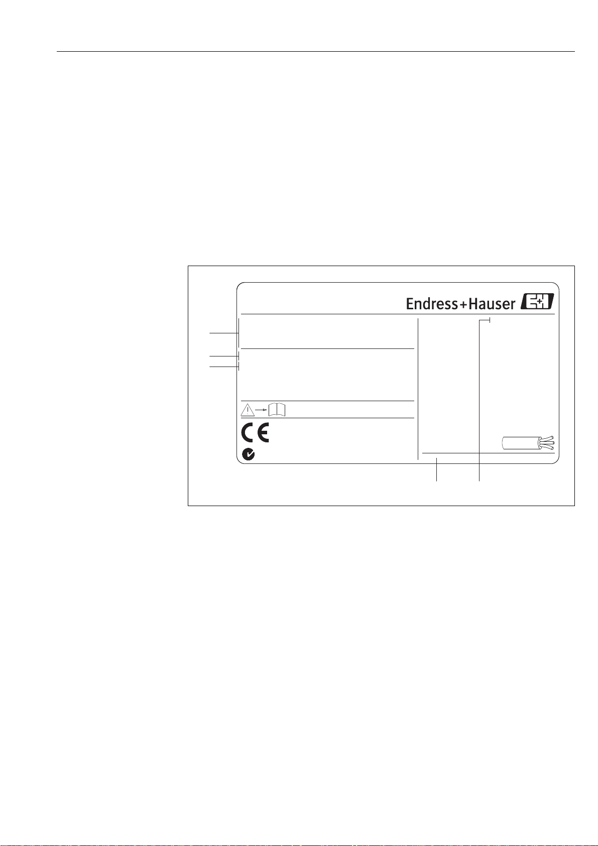
2.1.1 Nameplate of the transmitter
a0006111
Fig. 1: Nameplate specifications for the "Prosonic Flow" transmitter (example)
1 Order code / serial number: See the specifications on the order confirmation for the meanings of the individual
letters and digits
2 Power supply: 12 to 35 V DC
Power consumption: 1.2 W
3 Available outputs
4 Permitted ambient temperature range
5 Degree of protection
Endress+Hauser 7
Page 8
Identification Proline Prosonic Flow 92F
2
3
4
5
1
7
6
Switzerland
4153 Reinach
-40°C <Tamb< +80°C
-40° <TambF < +176°F
IP67 / NEMA/Type4X
5P-CAL
TM:
-40°C(-40°F)...+150°C(+302°F)
CF3M / 1.4404 / F316L / F316
Materials:
DN100/4" DIN/EN PN16
1.000/0000
K-factor:
XXXXXXXXXXX
Ser.No.:
Order Code:
Prosonic Flow F
92FXX-XXXXXXXXXXXXX
N12895
i
8
Connector
Plug
Observer manuel d'Instruction.
4..20mA
max. 36VDC
max. 36VDC
max. 15mA
Optional
Betriebsanleitung beachten.
See operating manual.
1
3
4
2
Do not sep rate when energized!a
ATEXII3G / Zone 2:
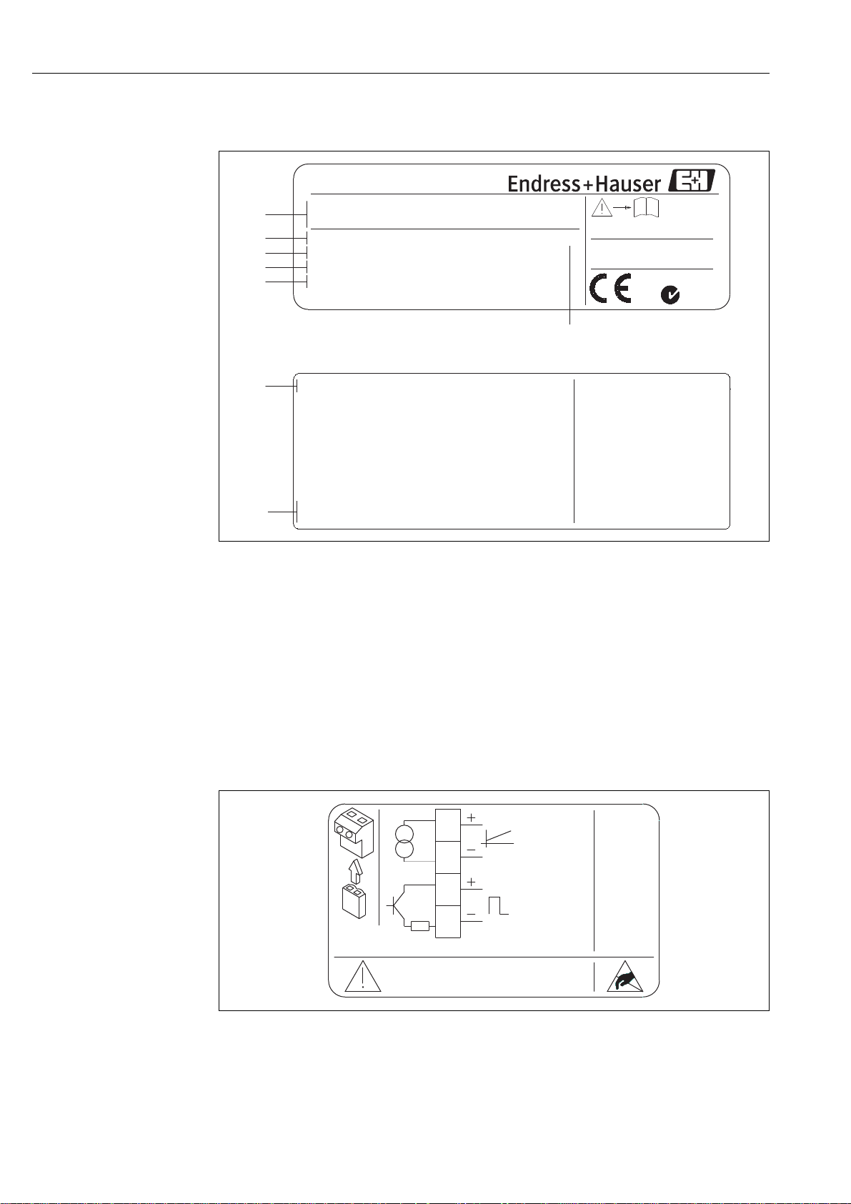
2.1.2 Nameplate of the sensor
a0006107
Fig. 2: Nameplate specifications for the Prosonic Flow F sensor (example)
1 Order code/serial number: See the specifications on the order confirmation for the meanings of the individual
letters and digits
2 Calibration factor with zero point
3 Device nominal diameter/nominal pressure
4 Measuring tube material
5 Medium temperature range
6 Degree of protection
7 Permitted ambient temperature range
8 Additional information (examples):
– 5P-CAL: with 5-point calibration
2.1.3 Nameplate for connections
Fig. 3: Nameplate specifications for Proline transmitter (example)
8 Endress+Hauser
a0006110
Page 9

Proline Prosonic Flow 92F Identification
2.2 Certificates and approvals
The devices are designed in accordance with good engineering practice to meet state-of-the-art
safety requirements, have been tested, and left the factory in a condition in which they are safe to
operate.
The measuring device complies with the general safety requirements in accordance with EN 61010,
the EMC requirements of IEC/EN 61326 and NAMUR recommendations NE 21 and NE 43.
The measuring system described in these Operating Instructions thus complies with the statutory
requirements of the EC Directives. Endress+Hauser confirms successful testing of the device by
affixing to it the CE mark.
The measuring system complies with the EMC requirements of the Australian Communications and
Media Authority (ACMA).
!
Note!
A detailed list of all the certificates and approvals is provided in the technical data on Page 66.
2.3 Registered trademarks
HART®
Registered trademark of the HART Communication Foundation, Austin, USA
®
HistoROM™ T-DAT
Registered or registration-pending trademarks of Endress+Hauser Flowtec AG, Reinach, CH
, FieldCare ®, Fieldcheck®, FieldXpert™, Applicator
®
Endress+Hauser 9
Page 10
Installation Proline Prosonic Flow 92F
3 Installation
3.1 Incoming acceptance, transport, storage
3.1.1 Incoming acceptance
On receipt of the goods, check the following points:
• Check the packaging and the contents for damage.
• Check the shipment, make sure nothing is missing and that the scope of supply matches your
order.
3.1.2 Transport
Please note the following when unpacking or transporting to the measuring point:
• The devices must be transported in the container supplied.
• The covers or caps fitted to the process connections prevent mechanical damage to the sealing
faces and the ingress of foreign matter to the measuring tube during transportation and storage.
Consequently, do not remove these covers or caps until immediately before installation.
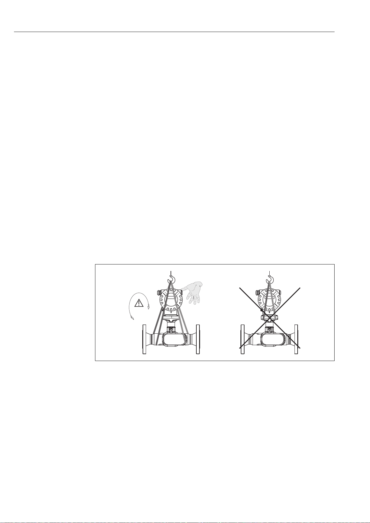
• Devices with nominal diameters > DN 40 (> 1½") may not be lifted at the transmitter housing or
at the connection housing of the remote version when transporting. Use carrier slings when
transporting and put the slings around both process connections. Avoid chains as these could
damage the housing.
#
Warning!
Risk of injury if the measuring device slips. The center of gravity of the entire measuring device
might be higher than the points around which the slings are slung.
Therefore, when transporting, make sure that the device does not unintentionally turn or slip.
a0005765
Fig. 4: Instructions for transporting sensors with a nominal diameter > DN 40 (> 1½")
3.1.3 Storage
Note the following points:
• Pack the measuring device in such a way as to protect it reliably against impact for storage (and
transportation). The original packaging provides optimum protection.
• The permissible storage temperature is –40 to +80 °C (–40 °F to 176 °F),
preferably +20 °C (68 °F).
• Do not remove the protective covers or caps on the process connections until you are ready to
install the device.
• The measuring device must be protected against direct sunlight during storage in order to avoid
unacceptably high surface temperatures.
10 Endress+Hauser
Page 11
Proline Prosonic Flow 92F Installation
1
2
3
4
5
3.2 Installation conditions
Note the following points:
• No special measures such as supports are necessary. External forces are absorbed by the
construction of the instrument.
• The flowmeter flanges must be coplanar with connecting flanges and free from tension.
• The maximum permitted ambient temperatures (→ ä 63) and fluid temperatures (→ ä 63)
must be observed.
• Pay particular attention to the notes on orientation and piping insulation on the following pages.
• The correct operation of the measuring system is not influenced by pipe vibrations.
3.2.1 Dimensions
All the dimensions and lengths of the sensor and transmitter are provided in the separate
documentation "Technical Information". → ä 67
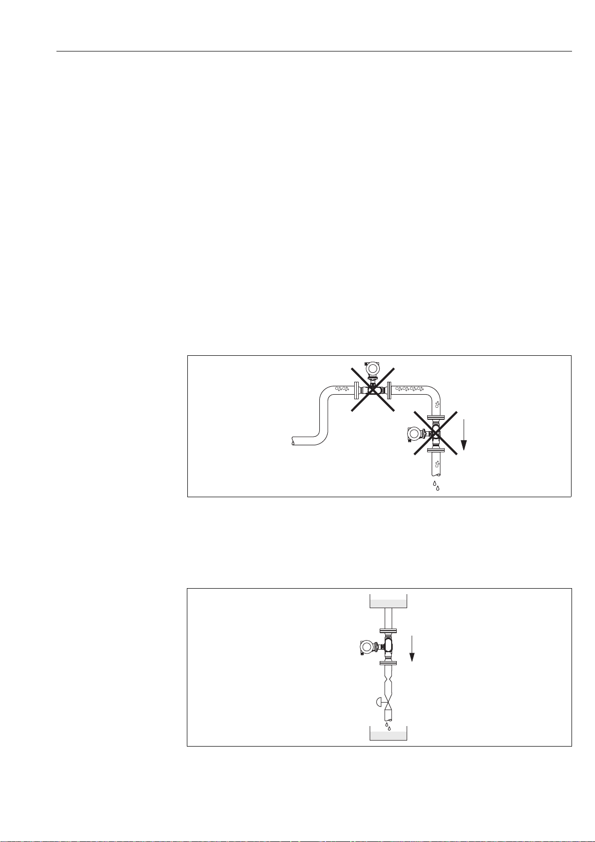
3.2.2 Mounting location
Accumulated gas bubbles in the measuring tube can result in measuring errors.
Avoid the following locations:
• Highest point of a pipeline. Risk of gas accumulating.
• Directly upstream of a free pipe outlet in a vertical pipeline.
a0006081
Fig. 5: Mounting location
The proposed configuration in the following diagram, however, permits installation in a vertical
pipeline. Pipe restrictors or the use of an orifice plate with a smaller cross section than the nominal
diameter prevent the sensor from running empty during measurement.
Fig. 6: Installation in a vertical pipe (e.g. for batching applications)
1 = Supply tank , 2 = Sensor, 3 = Orifice plate, pipe restriction , 4 = Valve, 5 = Batching tank
a0006082
Endress+Hauser 11
Page 12
Installation Proline Prosonic Flow 92F
A BC D
System pressure
No additional pressure loss results from installing the device. It is important to ensure that cavitation
or degassing does not occur at fittings upstream from the measuring device as this can affect sound
transmission in the fluid.
No special measures need to be taken for fluids which have properties similar to water under normal
conditions.
In the case of liquids with a low boiling point (hydrocarbons, solvents, liquefied gases) or in suction
lines, it is important to ensure that pressure does not drop below the vapor pressure and that the
liquid does not start to boil. It is also important to ensure that the gases that occur naturally in many
liquids do not outgas. Such effects can be prevented when system pressure is sufficiently high.
For this reason, preference should be given to the following mounting locations:
• Downstream from pumps (no danger of vacuum)
• At the lowest point in a vertical pipe
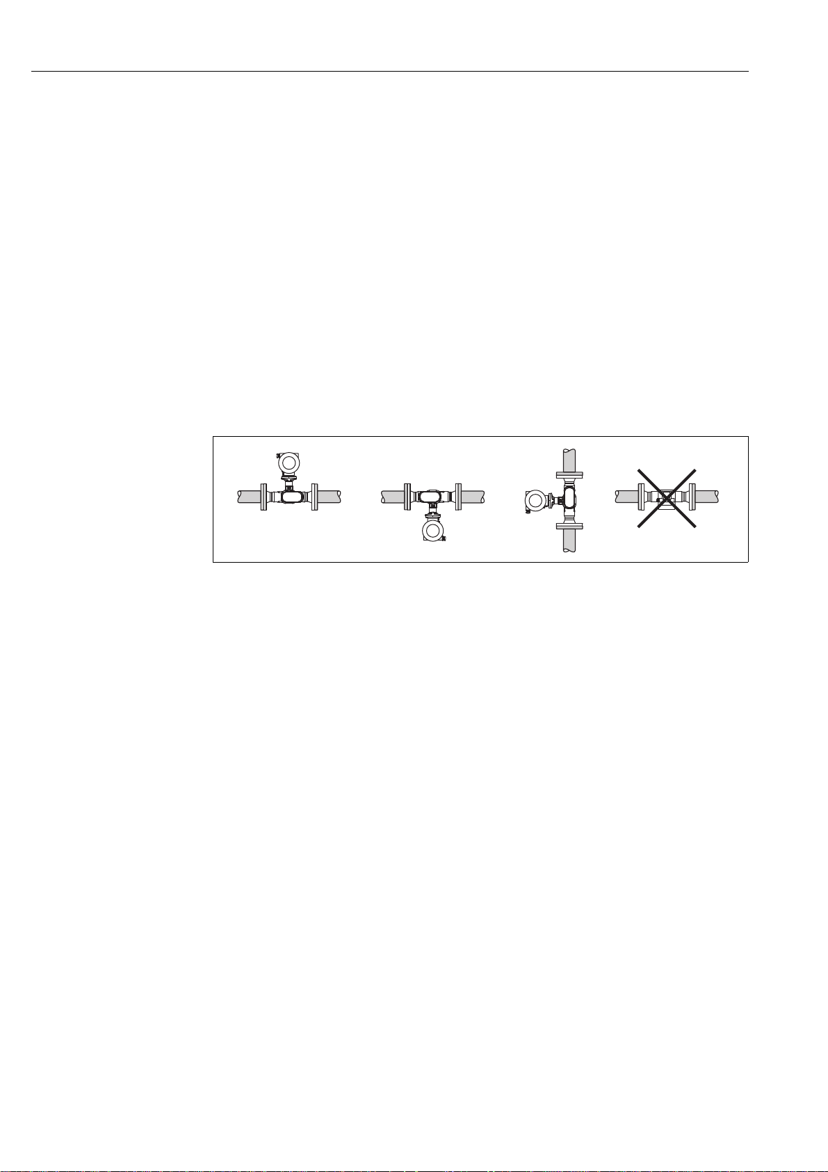
3.2.3 Orientation
Make sure that the direction of the arrow on the nameplate of the sensor matches the direction of
flow (direction in which the fluid flows through the pipe).
Fig. 7: Orientations A, B and C recommended, orientation D only recommended under certain circumstances
3.2.4 Heating
Some fluids require heat to be transfered at the sensor. Heating can be electric, e.g. with heated
elements, or by hot water or steam.
Caution!
"
• Danger of electronics overheating!
Make sure that the adapter between the sensor and transmitter and the connection housing of
the remote version always remain free of insulating material.
• When using electrical heat tracing whose heat is regulated using phase control or by pulse packs,
it cannot be ruled out that the measured values are influenced by magnetic fields which may
occur, (i.e. at values greater than those permitted by the EC standard (Sinus 30 A/m)). In such
cases, the sensor must be magnetically shielded.
a0005971
12 Endress+Hauser
Page 13
Proline Prosonic Flow 92F Installation
max. 20 (0.8)
max. 20 (0.8)
mm (inch)
2
A
1
3
A
A
4
A
5DN×
10 DN×
B
3 DN×
15 DN×
5 × DN
B
3 DN×
B
3 DN×
B
3 DN×
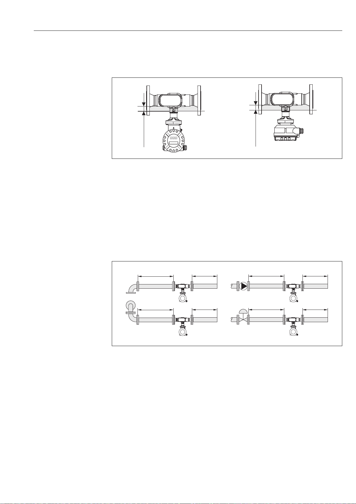
3.2.5 Thermal insulation
Some fluids require suitable measures to avoid loss of heat at the sensor. A wide range of materials
can be used to provide the required thermal insulation.
a0005763-ae
Fig. 8: A maximum insulation thickness of 20 mm (0.8 inch) must be observed in the area of the electronics/neck.
If the device is installed horizontally (with transmitter head pointing upwards), an insulation
thickness of min. 10 mm (0.4") is recommended to reduce convection. The maximum insulation
thickness of 20 mm (0.8") must not be exceeded.
3.2.6 Inlet and outlet run
If possible, install the sensor well clear of fittings such as valves, T-pieces, elbows, etc. As a
minimum, the inlet and outlet runs shown below must be observed to achieve the specified
accuracy of the device. The longest inlet run shown must be observed if two or more flow
disturbances are present.
A0006267
Fig. 9: Minimum inlet and outlet runs with various flow obstructions (values given for 3 and 4 path versions)
A = Inlet run, B = Outlet run, 1 = 90° elbow or T-piece, 2 = Pump, 3 = 2 × 90° elbow, 3-dimensional, 4 = Control valve
3.2.7 Limiting flow
Information on limiting flow is provided under "Measuring range" in the technical data section.
Endress+Hauser 13
Page 14
Installation Proline Prosonic Flow 92F
180°
180°
3.3 Installation instructions
3.3.1 Mounting the sensor
• Prior to installing the measuring device in the piping, remove all traces of transport packaging and
any protective covers from the sensor.
• Make sure that the internal diameters of seals are the same as, or greater than, those of the
measuring device and piping. If seals with a smaller internal diameter are used, this affects the
flow and results in inaccurate measurement.
• Ensure that the arrow on the measuring tube matches the direction of flow in the piping.
• For Carbon steel option remove transport protection coating using mineral spirit (optional).
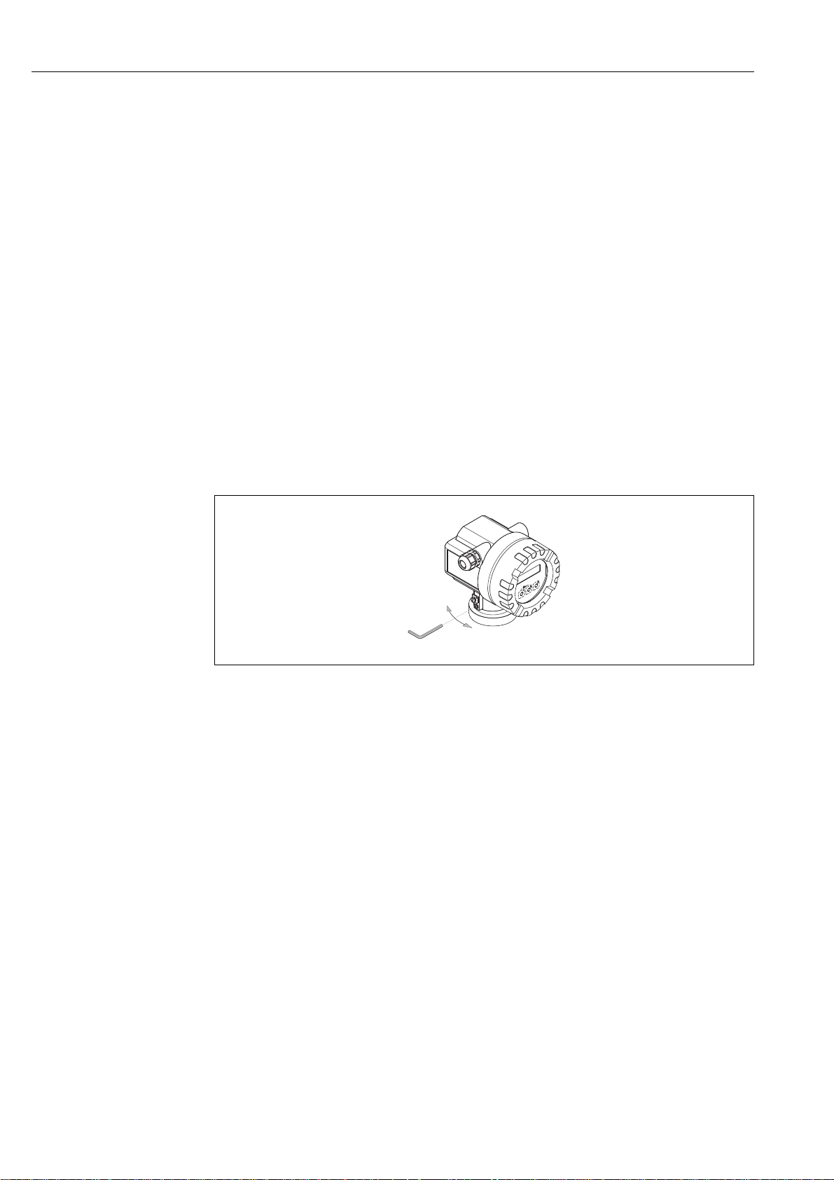
3.3.2 Turning the transmitter housing
1. Loosen the safety screw.
2. Turn the transmitter housing to the desired position (max. 180° in each direction to the stop).
Note!
!
There are recesses in the rotating groove at 90° stages (only compact version).
These help you align the transmitter easier.
3. Retighten the securing screw.
Fig. 10: Turning the transmitter housing
3.3.3 Turning the local display
1. Unscrew the cover of the electronics compartment from the transmitter housing.
2. Remove the display module from the transmitter retainer rails.
3. Turn the display to the desired position (max. 4 x 45° in each direction) and
reset it onto the retaining rails.
4. Screw the cover of the electronics compartment firmly back onto the transmitter housing.
a0005766
14 Endress+Hauser
Page 15
Proline Prosonic Flow 92F Installation
ANSCHLUSSKLEMMEN - FIELD TERMINALS
ANSCHLUSSKLEMMEN - FIELD TERMINALS
AB
232 (9.13)
227 (8.94)
mm (inch)
*226 (*8.90)
*221 (*8.70)
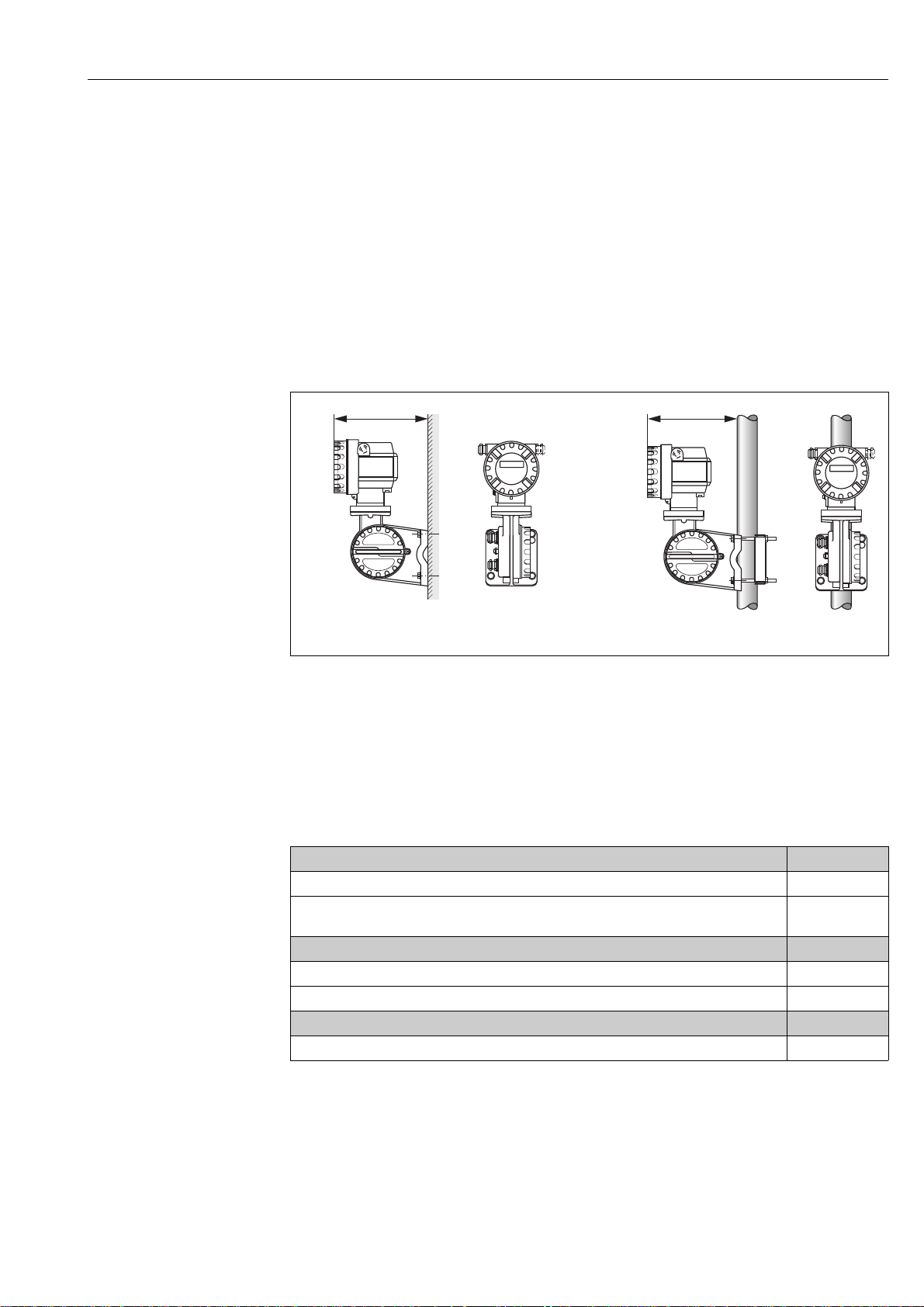
3.3.4 Mounting the remote version
The transmitter can be mounted in the following ways:
• Wall mounting
• Pipe mounting (with separate mounting kit, accessories) → ä 45
Caution!
"
When mounting on a pipe, the ambient temperature range may not be exceeded.
→ ä 63
The transmitter and the sensor must be mounted separate in the following circumstances:
• Poor accessibility
• Lack of space
• Extreme ambient temperatures
Mount the transmitter as illustrated in the diagram.
Fig. 11: Mounting the transmitter (remote version)
A Direct wall mounting
B Pipe mounting
* Dimensions for version without local display
3.4 Post-installation check
Perform the following checks after installing the measuring device:
Device condition and specifications Notes
Is the device damaged (visual inspection)? -
Do the process temperature/pressure, ambient temperature, measuring range etc. correspond to the
specifications of the device?
Installation Notes
Does the arrow on the sensor or sensor neck match the direction of flow through the pipe? -
Are the measuring point number and labeling correct (visual inspection)? –
Process environment / process conditions Notes
Is the measuring device protected against direct sunlight? -→ ä 63
→ ä 5
a0005947-ae
Endress+Hauser 15
Page 16
Wiring Proline Prosonic Flow 92F
a
c
b
d
1
G
1
GROUND
2
GROUND
2
G
1G2
G
1
GROUND
2
GROUND
3G
3
GROUND
4
GROUND
4 G
3
GROUND
4
GROUND
5G
5
GROUND
6
GROUND
6G
5
GROUND
6
GROUND
7
G
7
GROUND
8
GROUND
8G
7
GROUND
8
GROUND
3G
4
G5G6G7G8G
1
2
3
4
5
6 7
8
e
f
4 Wiring
4.1 Connecting the remote version
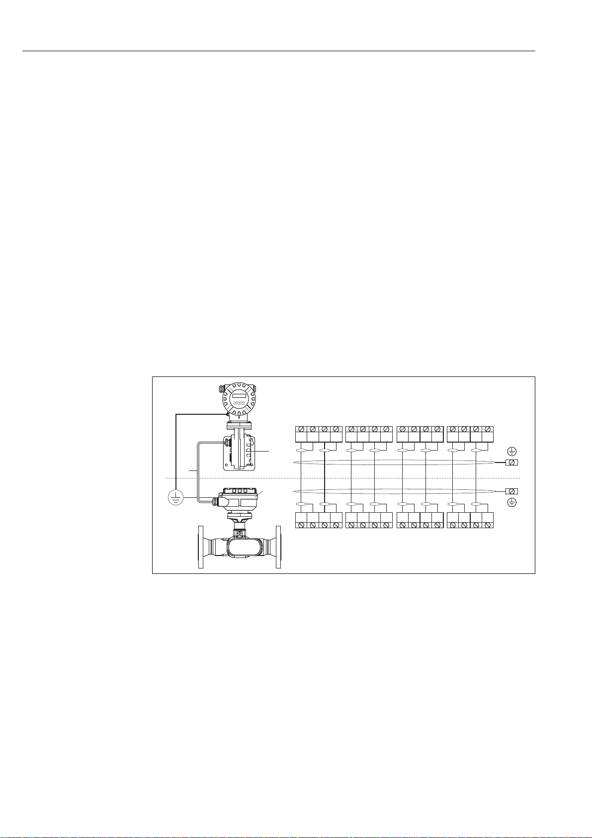
4.1.1 Connecting cable for sensor/transmitter
!
Note!
• The remote version must be grounded. In doing so, the sensor and transmitter must be connected
to the same potential matching (see Fig. 12, d).
• You may only connect the sensor to the transmitter with the same serial number (see nameplate).
Communication errors can occur if this is not observed when connecting the devices.
Procedure
1. Remove the covers of the connection compartments (a/b).
2. Feed the connecting cable (c) through the appropriate cable entries.
3. Wire the sensor and transmitter in accordance with the electrical connection diagram:
see Fig. 12 or the wiring diagram in the cover of the connection compartment.
4. Connect the appropriate cable shield (e/f).
5. Firmly tighten the glands of the cable entries.
6. Screw the covers of the connection compartments (a/b) back on.
Fig. 12: Connecting the remote version
a Cover of the connection compartment (transmitter)
b Cover of the connection compartment (sensor)
c Connecting cable (signal cable)
d Identical potential matching for sensor and transmitter
e Connect the shielding to the ground terminal in the transmitter housing and keep it as short as possible
f Connect the shielding to the ground terminal in the connection housing
4.1.2 Cable specification for connecting cable
Only use the cables supplied by Endress+Hauser and pre-terminated at the factory. The cables are
16 Endress+Hauser
available with a fixed length of 10 m (30 feet) and 30 m (90 feet) and optionally available with
variable lengths ranging from 1 m (3 feet) to max. 50 m (150 feet). The cable sheathing is made of
PVC.
a0005764
Page 17

Proline Prosonic Flow 92F Wiring
4.2 Connecting the measuring unit
4.2.1 Connecting the transmitter
#
!
Warning!
When connecting Ex-certified devices, see the notes and diagrams in the Ex-specific supplement to
these Operating Instructions. Please do not hesitate to contact your Endress+Hauser representative
if you have any questions.
Note!
• Observe national regulations governing the installation of electrical equipment.
• The remote version must be grounded. In doing so, the sensor and transmitter must be connected
to the same potential matching.
• When connecting the transmitter, use a connecting cable with a continuous service temperature
range between –40 °C (–40 °F) and the permitted max. ambient temperature plus 10 °C (plus 18 °F)
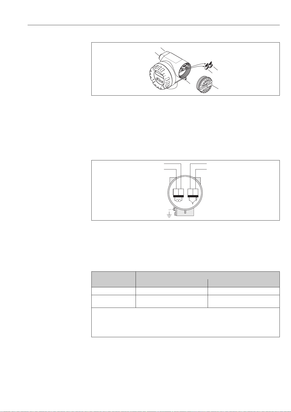
Connecting the transmitter, non-Ex/Ex-i version (→ å 13)
1. Unscrew the cover (a) of the electronics compartment from the transmitter housing.
2. Remove the display module (b) from the retaining rails (c) and refit onto the right retaining rail
with the left side of the display (this secures the display module).
3. Loosen screw (d) of the cover of the connection compartment and fold the cover down.
4. Push the cable for the power supply current output through the cable gland (e).
Optional: push the cable for the pulse output/frequency output through the cable gland (f).
5. Pull the terminal connector (g) out of the transmitter housing and connect the cable for the
power supply/current output. (→ Fig. 14, A)
Optional: pull terminal connector (h) out of the transmitter housing and connect the cable for
the pulse output/frequency output. (→ Fig. 14, B)
Note!
!
The terminal connectors (g / h) are pluggable, i.e. they can be plugged out of the transmitter
housing to connect the cables.
6. Plug the terminal connectors (g / h) into the transmitter housing.
Note!
!
The connectors are coded so you cannot mix them up.
7. Only remote version:
secure the ground cable to the ground terminal (→ Fig. 14, C).
8. Tighten the cable glands (e / f) (see alsoPage 21).
9. Fold up the cover of the connection compartment and tighten the screws (d).
10. Remove the display module (b) and fit on the retaining rails (c).
11. Screw the cover of the electronics compartment (a) onto the transmitter housing.
Endress+Hauser 17
Page 18

Wiring Proline Prosonic Flow 92F
e
f
g
h
d
a
c
b
d
a0001895
Fig. 13: Connecting the transmitter, non-Ex/Ex i version
a Cover of electronics compartment
b Display module
c Retaining rail for display module
d Connection compartment cover
e Cable gland for power supply/current output cable
f Cable gland for pulse output/frequency output cable (optional)
g Terminal connector for power supply/current output
h Terminal connector for pulse output/frequency output (optional)
Connecting the transmitter, Ex-d → å 14
1. Open the clamp (a) securing the cover of the connection compartment.
2. Unscrew the cover (b) of the connection compartment from the transmitter housing.
3. Push the cable for the power supply/current output through the cable gland (c).
Optional: push the cable for the pulse output/frequency output through the cable gland (d).
4. Pull the terminal connector (e) out of the transmitter housing and connect the cable for the
power supply/current output. (→ Fig. 14, A)
Optional: pull terminal connector (f) out of the transmitter housing and connect the cable for
the pulse output/frequency output. (→ Fig. 14, B)
Note!
!
The terminal connectors (e/f) are pluggable, i.e. they can be plugged out of the transmitter
housing to connect the cables.
5. Plug the terminal connectors (e / f) into the transmitter housing.
Note!
!
The connectors are coded so you cannot mix them up.
6. Only remote version:
secure the ground cable to the ground terminal (→ Fig. 14, C).
7. Tighten the cable glands (c / d) (see alsoPage 21).
8. Secure the ground cable to the ground terminal (only remote version)
9. Screw the cover (b) of the connection compartment onto the transmitter housing.
10. Tighten the clamp (a) securing the cover of the connection compartment.
18 Endress+Hauser
Page 19
Proline Prosonic Flow 92F Wiring
f
e
b
a
c
d
12 34
A
C
++
--
B
a0001896
Fig. 14: Connecting the transmitter, Ex d version
a Clamp securing cover of connection compartment
b Cover of connection compartment
c Cable gland for power supply/current output cable
d Cable gland for pulse output/frequency output cable (optional)
e Terminal connector for power supply/current output
f Terminal connector for pulse output/frequency output (optional)
Wiring diagram
A0014635
Fig. 15: Assignment of terminals
A Power supply/current output
B Optional pulse output/status output
C Ground terminal (only relevant for remote version)
4.2.2 Terminal assignment
Terminal No. (inputs/outputs)
Order version 1 – 2 3 – 4
92***-***********W HART current output –
92***-***********A HART current output
HART current output
Galvanically isolated, 4 to 20 mA with HART
Pulse/status output
Open collector, passive, galvanically isolated, Umax = 30 V, with 15 mA current limiting, Ri = 500 Ω, can be configured
as pulse output or status output
Pulse/status output/
frequency output
Endress+Hauser 19
Page 20
Wiring Proline Prosonic Flow 92F
+1
–2
1
3
4
1
# % &
Copy
G H I
PQ R S
, ( )‘
AB C
Paste
Page
On
Page
Up
DeleteBksp
Insert
J K L
TU V
_ < >
D E F
Hot Key
+ Hot Key
M N O
W XYZ
+ * /
4
7
.
2
5
8
0
375
FIELD COMMUNICATOR
3
6
9
-
9
6
³W250
12 34
++
--
2
+26
-27
RS 232
1
3
5
4
³W250
12 34
++
--
2
4.2.3 HART connection
Users have the following connection options at their disposal:
• Direct connection to transmitter by means of terminals 1 (+) / 2 (−)
• Connection by means of the 4 to 20 mA circuit
!
Note!
• The measuring circuit's minimum load must be at least 250 Ω .
• After commissioning, make the following setting:
Switch HART write protection on or off (see Page 38)→ Page 37
• For connecting, please refer also to the documentation issued by the HART Communication
Foundation, in particular HCF LIT 20: "HART, a technical summary".
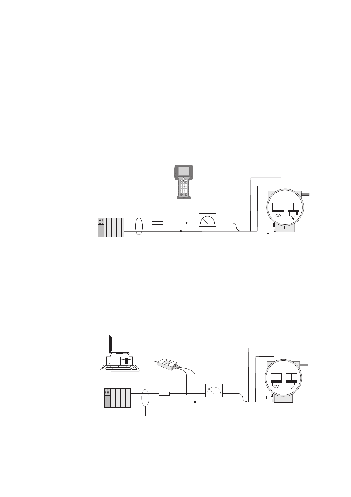
Connecting the HART handheld terminal
For the connection, also refer to the documentation issued by the HART Communication
Foundation, and in particular HCF LIT 20: "HART, a technical summary".
A0014632
Fig. 16: Electrical connection to the HART operating terminal
1HART operating terminal
2Power supply
3 Shielding
4 Additional switching units or PLC with passive input
Connecting a PC with operating software
A HART modem (e.g. "Commubox FXA195") is required for connecting a PC with operating
software (e.g. "FieldCare").
For the connection, also refer to the documentat
ion issued by the HART Communication
Foundation, and in particular HCF LIT 20: "HART, a technical summary".
20 Endress+Hauser
Fig. 17: Electrical connection of a PC with operating software
1 PC with operating software
2Power supply
3 Shielding
4 Additional switching units or PLC with passive input
5 HART modem e.g. Commubox FXA195
A0014633
Page 21
Proline Prosonic Flow 92F Wiring
a b
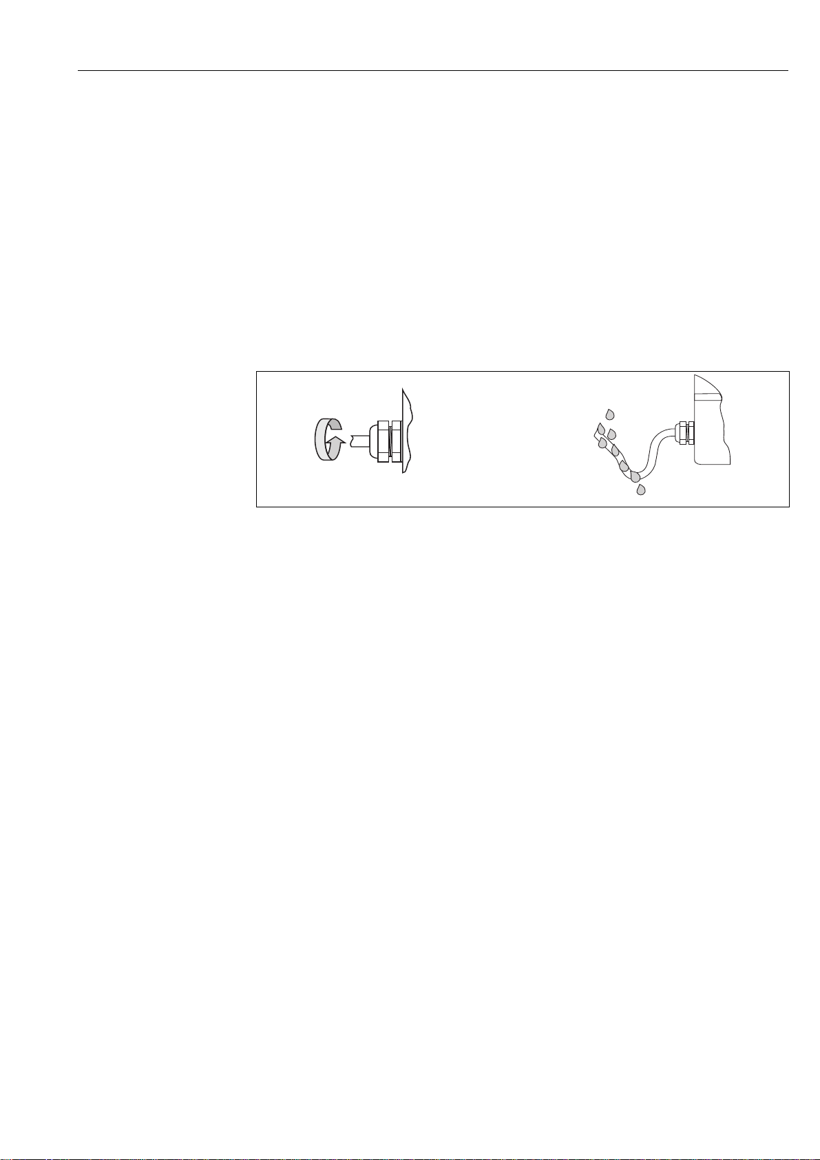
4.3 Degree of protection
The devices fulfill all the requirements for IP 67 (optional IP 68) degree of protection. Compliance
with the following points is mandatory following installation in the field or servicing in order to
ensure that IP 67 protection is maintained:
• The housing seals must be clean and undamaged when inserted into their grooves. The seals must
be dried, cleaned or replaced if necessary.
• All housing screws and screw caps must be firmly tightened.
• The cables used for connection must be of the specified outside diameter.
• Firmly tighten the cable entries.
• The cables must loop down before they enter the cable entries ("water trap").
This arrangement prevents moisture penetrating the entry. Always install the measuring device
in such a way that the cable entries do not point up.
• Replace all unused cable entries with dummy plugs.
• Do not remove the grommet from the cable entry.
"
!
a0001914
Fig. 18: Installation instructions for cable entries
Caution!
The cable glands of the sensor housing must not be released as the degree of protection guaranteed
by Endress+Hauser would no longer apply.
Note!
The Prosonic Flow 92F can be supplied with IP 68 rating (permanent immersion in water to a depth
ot 3 meters /10 ft). In this case the transmitter must be installed remote from the sensor.
Endress+Hauser 21
Page 22

Wiring Proline Prosonic Flow 92F
4.4 Post-connection check
Perform the following checks after completing electrical installation of the measuring device:
Device condition and specifications Notes
Are cables or the device damaged (visual inspection)? −
Electrical connection Notes
Does the supply voltage match the specifications on the nameplate?
• Non-Ex: 12 to 35 V DC (with HART: 18 to 35 V DC)
• Ex i and Ex n: 12 to 30 V DC (with HART 18 to 30 V DC)
• Ex d: 15 to 35 V DC (with HART 21 to 35 V DC)
Do the cables used comply with the specifications? → ä 16, → ä 62
Do the cables have adequate strain relief? −
Are the cables for power supply/current output, frequency output (optional) and
grounding connected correctly?
Remote version only:
Is the connecting cable between the sensor and transmitter connected correctly?
Remote version only:
Are the sensor and transmitter connected to the same potential matching?
Are all screw terminals firmly tightened? −
Are all the cable entries installed, tightened and sealed?
Cable run with "water trap"?
Are all the housing covers installed and tightened? −
−
→ ä 17
→ ä 16
→ ä 16
→ ä 21
22 Endress+Hauser
Page 23

Proline Prosonic Flow 92F Operation
Esc
E
+
-
1
32
+48.25 xx/yy
+3702.6 x
5Operation
5.1 Display and operating elements
The local display enables you to read important parameters directly at the measuring point and
configure the device using the "Quick Setup" or the function matrix.
The display consists of two lines; this is where measured values and/or status variables (e.g. bar
graph) are displayed.
By means of local operation, you can change the assignment of the display lines to different variables
to suit your needs and preferences. See Device Functions in the Appendix → ä 68
a0001141
Fig. 19: Display and operating elements
1 Liquid crystal display
The two-line liquid-crystal display shows measured values and diagnosis messages.
– Top line: shows main measured values, e.g. volume flow in [dm/h] or in [%].
– Bottom line: shows additional measured variables and status variables, e.g. totalizer reading in [dm], bar graph,
tag name.
– During commissioning or in the event of a fault in normal measuring operation, a diagnosis message flashes on
the screen.
The first line shows the diagnosis code beginning with the letters F, C, S or M and a short text containing the
2Plus/minus keys
3Enter key
diagnosis message appears on the second line.
– Enter numerical values, select parameters
– Select different function groups within the function matrix
Press the +/- keys simultaneously to trigger the following functions:
– Exit the function matrix step by step → HOME position
– Press and hold down +/- keys for longer than 3 seconds → return directly to the HOME position
–Cancel data entry
–HOME position→ enter the function matrix
– Save the numerical values you input or settings you changed
Endress+Hauser 23
Page 24
Operation Proline Prosonic Flow 92F
>3s
-
+
E
Esc
E
E
E
E
E E E E E
–
+
+
Esc
–
+
Esc
–
+
Esc
–
E
m
n
o
p
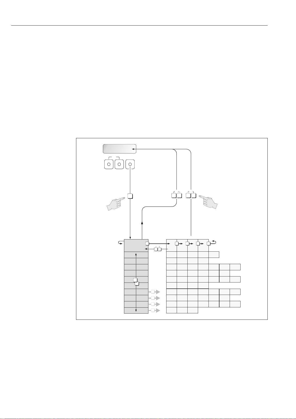
5.2 Operation via the function matrix
!
Note!
• Please refer to the general notes → ä 25
• Function descriptions → see the "Description of Device Functions" manual
1. HOME position → F → enter the function matrix
2. Select a function group e.g. CURRENT OUTPUT
3. Select a function (e.g. TIME CONSTANT)
Change parameter/enter numerical values:
P → select or enter enable code, parameters, numerical values
F → save your entries
4. Exit the function matrix:
– Press and hold down the Esc key (X) for more than 3 seconds → HOME position
– Repeatedly press Esc key (X) → return step by step to HOME position
Fig. 20: Selecting and configuring functions (function matrix)
24 Endress+Hauser
a0001142
Page 25

Proline Prosonic Flow 92F Operation
5.2.1 General notes
The Quick Setup menu is adequate for commissioning with the necessary standard settings.
Complex measuring operations on the other hand necessitate additional functions that you can
configure as necessary and customize to suit your process conditions. The function matrix,
therefore, comprises a multiplicity of additional functions which, for the sake of clarity, are arranged
in a number of function groups.
Comply with the following instructions when configuring functions:
• You select functions as described already.
• You can switch off certain functions (OFF). If you do so, related functions in other function groups
will no longer be displayed.
• Certain functions prompt you to confirm your data entries. Press P to select "SURE [ YES ]" and
press F to confirm. This saves your setting or starts a function, as applicable.
• Return to the HOME position is automatic if no key is pressed for 5 minutes.
• Programming mode is automatically disabled if you do not press a key within 60 seconds
following return to the HOME position.
!
!
"
Note!
A detailed description of all the functions required for commissioning is provided in Section 11.1
"Description of device functions".
Note!
• The transmitter continues to measure while data entry is in progress, i.e. the current measured
values are output via the signal outputs in the normal way.
• If the power supply fails, all preset and configured values remain safely stored in the EEPROM.
5.2.2 Enabling the programming mode
The function matrix can be disabled. Disabling the function matrix rules out the possibility of
inadvertent changes to device functions, numerical values or factory settings. A numerical code
(factory setting = 92) has to be entered before settings can be changed.
If you use a code number of your choice, you exclude the possibility of unauthorized persons
accessing data ( → see "Description of Device Functions" manual).
Comply with the following instructions when entering codes:
• If programming is disabled and the P operating elements are pressed in any function, a prompt
for the code automatically appears on the display.
• If "0" is entered as the private code, programming is always enabled.
• Your Endress+Hauser service organization can be of assistance if you are locked out of the device.
Caution!
Changing certain parameters influences numerous functions of the entire measuring device, and
may effect measuring accuracy!
There is no need to change these parameters under normal circumstances and consequently, they
are protected by a special service code known only to the Endress+Hauser service organization.
Please contact Endress+Hauser if you have any questions.
5.2.3 Disabling the programming mode
Programming mode is disabled if you do not press an operating element within 60 seconds following
automatic return to the HOME position.
You can also disable programming by entering any number (other than the private code) in the
ACCESS CODE function.
Endress+Hauser 25
Page 26

Operation Proline Prosonic Flow 92F
5.3 Communication
In addition to via local operation, the measuring device can also be configured and measured values
obtained by means of the HART protocol. Digital communication takes place using the 4–20 mA
current output HART.
The HART protocol allows the transfer of measuring and device data between the HART master and
the field devices for configuration and diagnostics purposes. HART masters, such as a handheld
terminal or PC-based operating programs (such as FieldCare), require device description (DD) files.
They are used to access all the information in a HART device. Such information is transferred solely
via "commands". There are three different command classes:
There are three different command classes:
• Universal commands
All HART devices support and use universal commands. The following functionalities are linked
to them:
– Recognizing HART devices
– Reading off digital measured values (volume flow, totalizer, etc.)
• Common practice commands:
Common practice commands offer functions which are supported and can be executed by many
but not all field devices.
• Device-specific commands:
These commands allow access to device-specific functions which are not HART standard. Such
commands access individual field device information, (among other things), such as empty-pipe/
full-pipe adjustment values, low flow cutoff settings etc.
!
Note!
The measuring device has all three command classes.
List of all "Universal Commands" and "Common Practice Commands": → ä 30
26 Endress+Hauser
Page 27

Proline Prosonic Flow 92F Operation
5.3.1 Operating options
For the complete operation of the measuring device, including device-specific commands, there are
device description (DD) files available to the user to provide the following operating aids and
programs:
!
Note!
• The HART protocol requires the "4 to 20 mA HART" setting (individual options see device
function) in the CURRENT SPAN function (current output 1).
HART Field Communicator Field Xpert
Selecting device functions with a HART Communicator is a process involving a number of menu
levels and a special HART function matrix.
The HART operating instructions in the carrying case of the HART handheld terminal contain more
detailed information on the device.
Operating program "FieldCare"
FieldCare is Endress+Hauser’s FDT-based plant asset management tool and allows the configuration
and diagnosis of intelligent field devices. By using status information, you also have a simple but
effective tool for monitoring devices.
Operating program "SIMATIC PDM" (Siemens)
SIMATIC PDM is a standardized, manufacturer independent tool for the operation, configuration,
maintenance and diagnosis of intelligent field devices.
Operating program "AMS" (Emerson Process Management)
AMS (Asset Management Solutions): program for operating and configuring devices.
Endress+Hauser 27
Page 28

Operation Proline Prosonic Flow 92F
5.3.2 Current device description files
The following table illustrates the suitable device description file for the operating tool in question
and then indicates where these can be obtained.
HART protocol:
Valid for software: 1.01.XX → Function "Device software"
Device data HART
Manufacturer ID:
Device ID:
HART version data: Device Revision 6/ DD Revision 1
Software release: 12.2010
Operating program: Sources for obtaining device descriptions:
Handheld terminal Field Xpert • Use update function of handheld terminal
FieldCare / DTM • www.endress.com → Download
AMS • www.endress.com → Download
SIMATIC PDM • www.endress.com → Download
(ENDRESS+HAUSER)
11
hex
61
hex
• CD-ROM (Endress+Hauser order number 56004088)
• DVD (Endress+Hauser order number 70100690)
→ Function "Manufact ID"
→ Function "Device ID"
!
Tester/simulator: Sources for obtaining device descriptions:
Fieldcheck • Update by means of FieldCare via the Flow Device FXA193/291 DTM
in the Fieldflash module
Note!
The "Fieldcheck" tester/simulator is used for testing flowmeters in the field. When used in
conjunction with the "FieldCare" software package, test results can be imported into a database,
printed out and used for official certification. Contact your Endress+Hauser representative for more
information.
28 Endress+Hauser
Page 29

Proline Prosonic Flow 92F Operation
5.3.3 Device variables and process variables
Device variables:
The following device variables are available via the HART protocol:
ID (decimal) Device variable
30 Volume flow
40 Sound velocity
43 Signal strength
49 Flow velocity
240 Totalizer 1
241 Totalizer 2
Process variables:
At the factory, the process variables are assigned to the following device variables:
• Primary process variable (PV) → volume flow
• Secondary process variable (SV) → totalizer
• Third process variable (TV) → sound velocity
• Fourth process variable (FV) → flow velocity
!
Note!
You can set or change the assignment of device variables to process variables using Command 51
→ ä 33.
Endress+Hauser 29
Page 30

Operation Proline Prosonic Flow 92F
5.3.4 Universal/common practice HART commands
The following table contains all the universal commands supported by the device.
Command No.
HART command/access type
Universal commands
0 Read the unique device identifier
Access type = Read
1 Read the primary process variable
Access type = Read
2 Read the primary process variable as
current in mA and percentage of the
set measuring range
Access type = Read
3 Read the primary process variable as
current in mA and four (preset
using command 51) dynamic
process variables
Access type = Read
Command data
(numeric data in decimal form)
None The device identifier provides information on the device
None – Byte 0: HART unit ID of the primary process variable
None – Byte 0-3: current current of the primary process
None 24 bytes are sent as a response:
Response data
(numeric data in decimal form)
and manufacturer; it cannot be altered.
The response consists of a 12-byte device ID:
– Byte 0: fixed value 254
– Byte 1: manufacturer ID, 17 = E+H
– Byte 2: device type ID, e.g. 0x61 = Prosonic 92
– Byte 3: number of preambles
– Byte 4: rev. no. universal commands
– Byte 5: rev. no. device-spec. Commands
– Byte 6: software revision
– Byte 7: hardware revision
– Byte 8: additional device information
– Byte 9-11: device identification
– Byte 1-4: primary process variable
Factory setting:
Primary process variable = volume flow
Note!
!
• You can set the assignment of device variables to
process variables using Command 51.
• Manufacturer-specific units are represented using the
HART unit ID "240".
variable in mA
– Byte 4-7: percentage of the set measuring range
Factory setting:
Primary process variable = volume flow
Note!
!
You can set the assignment of device variables to process
variables using Command 51.
– Byte 0-3: current of the primary process variable in
mA
– Byte 4: HART unit ID of the primary process variable
– Byte 5-8: primary process variable
– Byte 9: HART unit ID of the secondary process
variable
– Byte 10-13: secondary process variable
– Byte 14: HART unit ID of the third process variable
– Byte 15-18: third process variable
– Byte 19: HART unit ID of the fourth process variable
– Byte 20-23: fourth process variable
Factory setting:
• Primary process variable = volume flow
• Secondary process variable = totalizer 1
• Third process variable = sound velocity
• Fourth process variable = flow velocity
Note!
!
• You can set the assignment of device variables to
process variables using Command 51.
• Manufacturer-specific units are represented using the
HART unit ID "240".
30 Endress+Hauser
Page 31

Proline Prosonic Flow 92F Operation
Command No.
HART command/access type
6 Set HART short-form address
Access type = Write
11 Read the unique device identifier
using the TAG
Access type = Read
12 Read user message
Access type = Read
13 Read TAG, TAG description and
date
Access type = Read
14 Read sensor information on the
primary process variable
15 Read output information of the
primary process variable
Access type = Read
16 Read the device production number
Access type = Read
Command data
(numeric data in decimal form)
Byte 0: desired address (0 to 15)
Factory setting:
0
Note!
!
With an address >0 (multidrop mode), the current
output of the primary process variable is fixed to 4 mA.
Byte 0-5: TAG The device identifier provides information on the device
None Byte 0-24: user message
None – Byte 0-5: TAG
None – Byte 0-2: serial number of the sensor
None – Byte 0: alarm selection ID
None Byte 0-2: production number
Response data
(numeric data in decimal form)
Byte 0: active address
and manufacturer; it cannot be altered.
The response consists of a 12-byte device ID if the given
TAG matches the one saved in the device:
– Byte 0: fixed value 254
– Byte 1: manufacturer ID, 17 = E+H
– Byte 2: device type ID, 0x61 = Prosonic 92
– Byte 3: number of preambles
– Byte 4: rev. no. universal commands
– Byte 5: rev. no. device-spec. Commands
– Byte 6: software revision
– Byte 7: hardware revision
– Byte 8: additional device information
– Byte 9-11: device identification
Note!
!
You can write the user message using command 17.
– Byte 6-17: TAG description
– Byte 18-20: date
Note!
!
You can write the TAG, TAG description and date using
command 18.
– Byte 3: HART unit ID of the sensor limits and
measuring range of the primary process variable
– Byte 4-7: upper sensor limit
– Byte 8-11: lower sensor limit
– Byte 12-15: minimum span
Note!
!
• The data relate to the primary process variable (=
volume flow).
• Manufacturer-specific units are represented using the
HART unit ID "240".
– Byte 1: ID for transfer function
– Byte 2: HART unit ID for the set measuring range of
the primary process variable
– Byte 3-6: end of measuring range, value for 20 mA
– Byte 7-10: start of measuring range, value for 4 mA
– Byte 11-14: attenuation constant in [s]
– Byte 15: ID for write protection
– Byte 16: ID for OEM dealer, 17 = E+H
Factory setting:
Primary process variable = volume flow
Note!
!
• You can set the assignment of device variables to
process variables using Command 51.
• Manufacturer-specific units are represented using the
HART unit ID "240".
Endress+Hauser 31
Page 32

Operation Proline Prosonic Flow 92F
Command No.
HART command/access type
17 Write user message
Access = Write
18 Write TAG, TAG description and
date
Access = Write
Command data
(numeric data in decimal form)
You can save any 32-character long text in the device
with this parameter:
Byte 0-23: desired user message
You can save an 8-character TAG, a 16-character TAG
description and a date with this parameter:
–Byte 0-5: TAG
– Byte 6-17: TAG description
–Byte 18-20: date
Response data
(numeric data in decimal form)
Displays the current user message in the device:
Byte 0-23: current user message in the device
Displays the current information in the device:
–Byte 0-5: TAG
–Byte 6-17: TAG description
– Byte 18-20: date
The following table contains all the common practice commands supported by the device.
Command No.
HART command/access type
Common practice commands
33 Read measured values Byte 0: device variable ID for channel 0
34 Write attenuation constant for
primary process variable
Access = Write
35 Write measuring range of the
primary process variable
Access = Write
36 Set full scale value None None
37 Set lower range value None None
38 Device status reset "configuration
changed"
Access = Write
40 Simulate output current of the
primary process variable
Access = Write
42 Perform device reset
Access = Write
Command data
(numeric data in decimal form)
Byte 1: device variable ID for channel 1
Byte 2: device variable ID for channel 2
Byte 3: device variable ID for channel 3
Byte 0-3: attenuation constant of the primary process
variable in seconds
Factory setting:
Primary process variable = flow
Write the desired measuring range:
– Byte 0: HART unit ID for the primary process variable
– Byte 1-4: end of measuring range, value for 20 mA
– Byte 5-8: start of measuring range, value for 4 mA
Factory setting:
Primary process variable = flow
Note!
!
• You can set the assignment of device variables to
process variables using Command 51.
• If the HART unit ID does not suit the process variable,
the device will continue with the last valid unit.
None None
Simulation of the desired output current of the primary
process variable.
An entry value of 0 exits the simulation mode:
Byte 0-3: output current in mA
Factory setting:
Primary process variable = flow
Note!
!
You can set the assignment of device variables to process
variables with Command 51.
None None
Response data
(numeric data in decimal form)
Byte 0: device variable ID for channel 0
Byte 1: unit ID for channel 0
Byte 2-5: value of channel 0
Byte 6: device variable ID for channel 1
Byte 7: unit ID for channel 1
Byte 8-11: value of channel 1
Byte 12: device variable ID for channel 2
Byte 13: unit ID for channel 2
Byte 14-17: value of channel 2
Byte 18: device variable ID for channel 3
Byte 19: unit ID for channel 3
Byte 20-23: value of channel 3
Displays the current attenuation constant in the device:
Byte 0-3: attenuation constant in seconds
The measuring range currently set is shown as the
response:
– Byte 0: HART unit ID for the set measuring range of
the primary process variable
– Byte 1-4: end of measuring range, value for 20 mA
– Byte 5-8: start of measuring range, value for 4 mA
(is always at "0")
!
Manufacturer-specific units are represented using the
HART unit ID "240".
The current output current of the primary process
variable is displayed as a response:
Byte 0-3: output current in mA
Note!
32 Endress+Hauser
Page 33

Proline Prosonic Flow 92F Operation
Command No.
HART command/access type
44 Write unit of the primary process
variable
Access = Write
45 Zero point adjustment at the
current output
46 Span adjustment (adjustment of the
measuring range) at the current
output
48 Read extended device status
Access = Read
50 Read assignment of the device
variables to the four process
variables
Access = Read
51 Write assignments of the device
variables to the four process
variables
Access = Write
Command data
(numeric data in decimal form)
Specify the unit of the primary process variable.
Only units which are suitable for the process variable are
accepted by the device:
Byte 0: HART unit ID
Factory setting:
Primary process variable = flow
Note!
!
• If the written HART unit ID does not suit the process
variable, the device will continue with the last valid
unit.
• If you change the unit of the primary process variable,
this does not affect the system units.
Byte 0-3: measured current in mA The current output current of the primary process
Byte 0-3: measured current in mA The current output current of the primary process
None The current device status is displayed in extended form
None Display of the current variable assignment of the process
Specify device variables for the four process variables:
– Byte 0: device variable ID to the primary process
variable
– Byte 1: device variable ID to the secondary process
variable
– Byte 2: device variable ID to the third process variable
– Byte 3: device variable ID to the fourth process
variable
ID of the supported device variables:
See data → ä 29
Factory setting:
• Primary process variable = flow
• Secondary process variable = totalizer 1
• Third process variable = sound velocity
• Fourth process variable = flow velocity
Response data
(numeric data in decimal form)
The current unit code of the primary process variable is
displayed as a response:
Byte 0: HART unit ID
Note!
!
Manufacturer-specific units are represented using the
HART unit ID "240".
variable is displayed as a response:
Byte 0-3: output current in mA
variable is displayed as a response:
Byte 0-3: output current in mA
as the response:
Coding: see Table → Page 35
variables:
– Byte 0: device variable ID to the primary process
variable
– Byte 1: device variable ID to the secondary process
variable
– Byte 2: device variable ID to the third process variable
– Byte 3: device variable ID to the fourth process
variable
Factory setting:
• Primary process variable: ID 1 for flow
• Second process variable: code 250 for totalizer 1
• Third process variable: code 7 for sound velocity
• Fourth process variable: code 9 for flow velocity
Note!
!
You can set the assignment of device variables to process
variables with Command 51.
The variable assignment of the process variables is
displayed as a response:
– Byte 0: device variable ID to the primary process
variable
– Byte 1: device variable ID to the secondary process
variable
– Byte 2: device variable ID to the third process variable
– Byte 3: device variable ID to the fourth process
variable
Endress+Hauser 33
Page 34

Operation Proline Prosonic Flow 92F
Command No.
HART command/access type
53 Write device variable unit
Access = Write
54 Read information on the device
variables
Access = Read
59 Specify number of preambles in
message responses
Access = Write
Command data
(numeric data in decimal form)
This command sets the unit of the given device variables.
Only those units which suit the device variable are
transferred:
– Byte 0: device variable ID
– Byte 1: HART unit ID
ID of the supported device variables:
See data → ä 29
Note!
!
• If the written unit does not suit the device variable,
the device will continue with the last valid unit.
• If you change the unit of the device variable, this does
not affect the system units.
Byte 0: device variable ID Byte 0: device variable ID
This parameter specifies the number of preambles which
are inserted in the message responses:
Byte 0: number of preambles (2 to 20)
Response data
(numeric data in decimal form)
The current unit of the device variables is displayed in
the device as a response:
– Byte 0: device variable ID
– Byte 1: HART unit ID
Note!
!
Manufacturer-specific units are represented using the
HART unit ID "240".
Byte 1-3: serial number of the associated sensor
Byte 4: unit ID for device variable
Byte 5-8: upper limit of the device variable
Byte 9-12: lower limit of the device variable
Byte 13-16: time constant of device variable (unit: s)
As a response, the current number of the preambles is
displayed in the response message:
Byte 0: number of preambles
34 Endress+Hauser
Page 35

Proline Prosonic Flow 92F Operation
5.3.5 Device status/diagnosis code messages
You can read the extended device status, in this case, current diagnosis code messages, via
command "48". The command delivers bit-encoded information (see table below).
!
Note!
Detailed information on the device status messages and diagnosis code messages, and how they are
rectified, can be found in the Troubleshooting section on → ä 47
Byte Bit Diagnosis
code
0 0 284 Software update Loading new amplifier software version. No other commands
1 481 Diagnostic active
2 281 Initialization Initialization in progress. All outputs are set to 0.
3 411 Upload/download Uploading and downloading device files. No other commands
4 1 Device fault Serious device error
5 282-1 Data storage Error when accessing the amplifier EEPROM
6 282-2 Data storage Error when accessing the I/O module EEPROM
7 282-3 Data storage Error when accessing the T-DAT
1 0 283-1 Checksum error Data in the amplifier EEPROM faulty
1 283-2 Checksum error Data in the I/O module EEPROM faulty
2 283-3 Checksum error Data in the T-DAT EEPROM faulty
3 242 Incompatible SW The I/O board and the amplifier board are not compatible
4 62-1 Sensor connection Connection (down) sensor K1 / transmitter interrupted
5 62-2 Sensor connection Connection (up) sensor K1 / transmitter interrupted
6 62-3 Sensor connection Connection (down) sensor K2 / transmitter interrupted
7 62-5 Sensor connection Connection (up) sensor K2 / transmitter interrupted
2 0 62-5 Sensor connection Connection (down) sensor K3 / transmitter interrupted
1 62-6 Sensor connection Connection (up) sensor K3 / transmitter interrupted
2 62-7 Sensor connection Connection (down) sensor K4 / transmitter interrupted
3 62-8 Sensor connection Connection (up) sensor K4 / transmitter interrupted
4 283-4 Checksum error Totalizer checksum error
5 262 Module connection Internal communication error on the amplifier board
6 823-1 Ambient temp. The lower medium temperature limit for the thermosensor was
7 823-2 Ambient temp. The upper medium temperature limit for the thermosensor was
3 0 881-1 Sensor signal Channel 1: signal strength of the sensor too low
1 881-2 Sensor signal Channel 2: signal strength of the sensor too low
2 881-3 Sensor signal Channel 3: signal strength of the sensor too low
3 881-4 Sensor signal Channel 4: signal strength of the sensor too low
4 431-1 Adjust Zero point adjustment faulty
5 431-2 Adjust Channel 1: zero point adjustment faulty
6 431-3 Adjust Channel 2: zero point adjustment faulty
7 431-4 Adjust Channel 3: zero point adjustment faulty
Brief description of the message → ä 48
possible at this point.
possible at this point.
undershot
overshot
Endress+Hauser 35
Page 36

Operation Proline Prosonic Flow 92F
Byte Bit Diagnosis
code
4 0 431-5 Adjust Channel 4: zero point adjustment faulty
1 861-1 Medium Volume flow outside specified range.
2 861-2 Medium Flow velocity outside specified range.
3 861-3 Medium Signal strength outside specified range.
4 861-4 Medium Sound velocity outside specified range.
5 861-5 Medium Acceptance rate outside specified range.
6 861-6 Medium Profile factor outside specified range.
7 861-7 Medium Symmetry outside specified range.
5 0 412 Write backup Data backup to T-DAT failed
1 413 Read backup Error when accessing the T-DAT
2 461-1 Signal output Current adjustment active
3 453 Value suppression Positive zero return active
4 484 Simulation error Simulation of failsafe mode (outputs) active
5 485 Simulation value Measured variable simulation active
6 482-1 Simulation outp. Current output simulation active
7 482-2 Simulation outp. Simulation frequency output active
14 0 482-3 Simulation outp. Pulse output simulation active
1 482-4 Simulation outp. Status output simulation active
2 461-2 Signal output Current output: flow outside range
3 461-3 Signal output Frequency output: flow outside range
4 461-4 Signal output Pulse output: flow outside range
5 431-6 Adjust Zero point adjustment in progress
Brief description of the message → ä 48
36 Endress+Hauser
Page 37

Proline Prosonic Flow 92F Operation
a
b
c
A
ON
OFF
21 163264
4
8
d
ON
1 2 3 4 5 6 7 8
S
A
ON
1 2
4
0
B CD
e
ON
2345678
S
A
ON
12
4
0
1
5.3.6 Switching HART write protection on/off
Write protection can be activated or deactivated via switch block 2 (e/D).
The current status is displayed in the WRITE PROTECT function (see → ä 100).
1. Unscrew the cover of the electronics compartment from the transmitter housing.
2. Remove the display module (a) from the retaining rails (b) and refit onto right retaining rail with
the left side (this secures the display module).
3. Fold up the plastic cover (c).
4. At switch block 2 (e), move miniature switch 2 (D) to the desired position:
OFF position, miniature switch moved up = write protection deactivated ON position,
miniature switch moved down = write protection activated
5. Installation is the reverse of the removal procedure.
a0005949
Fig. 21: Switching HART write protection on/off
a Display module
b Retaining rails for the display module
cPlastic cover
dSwitch block 1:
– A (Miniature switches 1 to 7): not assigned/no function
– B (Miniature switch 8): not assigned/no function
eSwitch block 2:
– C (Miniature switch 1): not assigned/no function
– D (Miniature switch 2):
Switch write protection on/off
OFF = deactivated, write protection deactivated (miniature switch moved up)
ON = activated, write protection activated (miniature switch moved down)
(the current status of the write protection is displayed in the WRITE PROTECT function →→ä 100)
Endress+Hauser 37
Page 38

Commissioning Proline Prosonic Flow 92F
6 Commissioning
6.1 Function check
Make sure that the following function checks have been performed successfully before switching on
the supply voltage for the measuring device:
• "Post-installation check" checklist → ä 15
• "Post-connection check" checklist → ä 22
6.2 Switching on the measuring device
Once the function check has been performed successfully, the device is operational and can be
switched on via the supply voltage. The device then performs internal test functions and the
following messages are shown on the local display:
!
PROSONIC FLOW 92
V XX.XX.XX
Normal measuring mode commences as soon as device startup completes.
Various measured values and/or status variables appear on the display (HOME position).
Note!
If startup fails, an appropriate diagnosis code appears on the local display, depending on the cause.
→ ä 48
Displays the current software
38 Endress+Hauser
Page 39

Proline Prosonic Flow 92F Commissioning
+
+
+
E
HOME-POSITION
XXX.XXX.XX
E
m
n
o
Measuring Unit
Type
Unit Density
Unit Totalizer
Off valueLowflow cutoff
Value0/4 mA
Yes
Yes
No
No
Measuring Unit Type
Configuration another output ?
Automatically configuration display ?
Automatically
parameterization
of the display
Language
Quick
Set
up
Quick Setup
Commission
Flow Velocity
Flow
SonicVelocity
Quit
Current
output
Pulse /
Statusoutput
Selection output type
Unit
Flow Velocity
Unit Flow
Operation Density
Unit
SonicV
el
ocity
Operation
Mode
Pulse
Status
Assign
status
Pulse
value
Current
span
On
value
Pulse
width
Value
20 mA
Off
value
Output
signal
Time
constant
Time
constant
Failsafe
mode
Failsafe
mode
Time constant
Failsafe mode
Endvalue freq.
Value F Low
Value FHigh
Outputsignal
Frequency
On valueLowflow cutoff
Assign Lowflow cutoff
6.3 Quick Setup
In the case of measuring devices without a local display, the individual parameters and functions
must be configured via the configuration program, e.g. Fieldcare.
If the measuring device is equipped with a local display, all the important device parameters for
standard operation, as well as additional functions, can be configured quickly and easily by means
of the following Quick Setup menus.
6.3.1 "Commissioning" Quick Setup
Endress+Hauser 39
Fig. 22: "QUICK SETUP COMMISSIONING" menu for straightforward configuration of the major device functions
A0005762-en
Page 40

Commissioning Proline Prosonic Flow 92F
Note!
!
The display returns to the SETUP COMMISSIONING cell if you press the X key combination during interrogation.
The stored configuration remains valid.
m Only outputs not yet configured in the current Setup are offered for selection in each cycle.
n The "YES" option appears as long as a free output is still available.
The next poll is started if no more outputs are available.
o The "automatic parameterization of the display" option contains the following basic settings/factory settings:
•YES:
Line 1 = Volume flow or calculated Mass flow
Line 2 = Totalizer 1
• NO: the existing (selected) settings remain.
40 Endress+Hauser
Page 41

Proline Prosonic Flow 92F Commissioning
F
Esc
E
+
-
XXX.XXX.XX
F
F
F
F
F
F
P
P
P
P
N
O
T-DAT
SAVE/LOAD
Quick Setup
HOME
POSITION
LOAD
YES NO
CANCELSAVE
YES NO
Restart of the
measuring device
Input is
saved
6.3.2 Data backup with the T–DAT SAVE/LOAD function
The T-DAT SAVE/LOAD function can be used to save all the settings and parameters of the
measuring device on the HistoROM/T-DAT data storage device.
a0001221-en
Fig. 23: Data backup with the T-DAT SAVE/LOAD function
Access to HistoROM/T-DAT functions
The T-DAT SAVE/LOAD function is accessed via the QUICK SETUP function.
• Press F until the "QS COMMISSIONING NO" prompt appears.
• Press F until "QS COMMUNICATION NO" appears.
• Press F and the "CANCEL T-DAT SAVE/LOAD" prompt appears.
• Press the key or the S key and the prompt to enter the device input code appears.
• Enter the device input code and press F; programming is now enabled.
• Choose from the following options with the key or the S key:
–LOAD
Data in the HistoROM/T–DAT data storage unit are copied to the device memory (EEPROM).
This overwrites any settings and parameters of the device. The measuring device is restarted.
–SAVE
Settings and parameters are copied from the device memory (EEPROM) to the HistoROM/
T-DAT.
–CANCEL
Causes option selection to be aborted and the system to return to the higher selection level.
Application examples
• After commissioning, the current measuring point parameters can be saved to the HistoROM/
T-DAT as a backup.
• If the transmitter has to be replaced for some reason, the data can be loaded from the HistoROM/
T-DAT to the EEPROM of the new transmitter.
Endress+Hauser 41
Page 42

Commissioning Proline Prosonic Flow 92F
1
2
6.4 Adjust
6.4.1 Zero point adjustment
All measuring devices are calibrated with state-of-the-art technology. The zero point obtained in
this way is printed on the nameplate.
Calibration takes place under reference operating conditions. → ä 63
Consequently, the zero point adjustment is generally not necessary!
Experience shows that the zero point adjustment is advisable only in special cases:
• To achieve highest measuring accuracy with very small flow rates
• Under extreme process or operating conditions (e.g. very high process temperatures or very high
viscosity fluids)
Preconditions for a zero point adjustment
Note the following before you perform a zero point adjustment:
• A zero point adjustment can be performed only with fluids that contain no gas or solid contents.
• Zero point adjustment is performed with the measuring tubes completely filled and at zero flow
(v = 0 m/s). This can be achieved, for example, with shutoff valves upstream and/or downstream
of the sensor or by using existing valves and gates.
– Normal operation → valves 1 and 2 open
– Zero point adjustment with pump pressure → valve 1 open / valve 2 closed
– Zero point adjustment without pump pressure → valve 1 closed / valve 2 open
Fig. 24: Zero point adjustment and shutoff valves
Caution!
"
If the fluid is very difficult to measure (e.g. containing entrained solids or gas) it may prove
impossible to obtain a stable zero point despite repeated zero point adjustments. In instances of this
nature, please contact your Endress+Hauser service center.
Performing a zero point adjustment
1. Operate the system until operating conditions have settled.
2. Stop the flow (v = 0 m/s).
3. Check the shutoff valves for leaks.
4. Check that operating pressure is correct.
!
42 Endress+Hauser
5. Start the zero point adjustment (functional description, see → ä 101):
PROCESSPARAMETER → ZERO POINT ADJUSTMENT → START
Note!
The zero point value currently valid is displayed in the ZEROPOINT function → ä 102
a0006086
Page 43

Proline Prosonic Flow 92F Commissioning
6.5 Data storage device (HistoROM)
At Endress+Hauser, the term HistoROM refers to various types of data storage modules on which
process and measuring device data are stored. By plugging and unplugging such modules, device
configurations can be duplicated onto other measuring devices to cite just one example.
6.5.1 HistoROM/T-DAT (transmitter–DAT)
The T-DAT is an exchangeable data storage device in which all transmitter parameters and settings
are stored.
Storing of specific parameter settings from the EEPROM to the T-DAT and vice versa has to be
carried out by the user (= manual save function). Please refer to → ä 41 for a description of the
related function (T-DAT SAVE/LOAD) and the exact procedure for managing data.
Endress+Hauser 43
Page 44

Maintenance Proline Prosonic Flow 92F
7 Maintenance
No special maintenance work is required.
7.1 Exterior cleaning
When cleaning the exterior of measuring devices, always use cleaning agents that do not attack the
surface of the housing and the seals.
7.2 Cleaning with pigs
If pigs are used for cleaning, it is essential to take the inside diameters of measuring tube and process
connection into account. See also Technical Information.
44 Endress+Hauser
Page 45

Proline Prosonic Flow 92F Accessories
8 Accessories
Various accessories, which can be ordered separately from Endress +Hauser, are available for the
transmitter and the sensor. Your Endress+Hauser representative can provide detailed information
on the order codes in question.
8.1 Device-specific accessories
Accessory Description Order code
Transmitter
Proline Prosonic Flow 92
8.2 Measuring principle-specific accessories
Transmitter for replacement or for stock. Use the order
code to define the following specifications:
– Approvals
– Degree of protection/version
–Cable entry
– Display/power supply/operation
–Software
– Outputs/inputs
92XXXX - XXXXX * * * * * *
Accessory Description Order code
Mounting kit for
transmitter
Mounting kit for remote version, suitable for:
– Wall mounting
– Pipe mounting
DK8WM - B
8.3 Communication-specific accessories
Accessory Description Order code
Handheld terminal
HART Communicator
FieldXpert
FXA195 The Commubox FXA195 connects intrinsically safe Smart
Handheld terminal for remote configuration and for
obtaining measured values via the current output HART
(4 to 20 mA).
Contact your Endress+Hauser representative for more
information.
transmitters with HART protocol to the USB port of a
personal computer. This makes the remote operation of
the transmitters possible with the aid of configuration
programs (e.g. FieldCare).
Power is supplied to the Commubox by means of the USB
port.
SFX100 - * * * *
FXA195 – *
Endress+Hauser 45
Page 46

Accessories Proline Prosonic Flow 92F
8.4 Service-specific accessories
Accessory Description Order code
Applicator Software for selecting and planning flowmeters.
Applicator can be downloaded from the Internet or
ordered on CD-ROM for installation on a local PC.
Contact your Endress+Hauser representative for more
information.
Fieldcheck Tester/simulator for testing flowmeters in the field.
When used in conjunction with the "ToF Tool – Fieldtool
Package" software package, test results can be imported
into a database, printed and used for official certification.
Contact your Endress+Hauser representative for more
information.
FieldCare FieldCare is Endress+Hauser’s FDT-based plant asset
management tool. It can configure all intelligent field
units in your system and helps you manage them. By
using the status information, it is also a simple but
effective way of checking their status and condition.
Commubox FXA291 The Commubox FXA291 connects Endress+Hauser field
devices with a CDI (= Endress+Hauser Common Data
Interface) to the USB port of a computer or laptop.
This makes it possible to remotely operate and execute
service functions of field devices with the aid of an
Endress+Hauser operating program, e.g. FieldCare
software platform for plant-specific asset management.
FXA193 Service interface from the measuring device to the PC for
operation via FieldCare.
DKA80 – *
50098801
See the product page on the
Endress+Hauser website:
www.endress.com
51516983
FXA193 – *
46 Endress+Hauser
Page 47

Proline Prosonic Flow 92F Troubleshooting
9 Troubleshooting
9.1 Troubleshooting instructions
Always start troubleshooting with the following checklist if faults occur after commissioning or
during operation. This takes you directly (via various queries) to the cause of the problem and the
appropriate remedial measures.
Check the display
No display visible and no
output signals present
No display visible but
output signals are present
Display texts are in a
foreign language.
Measured value indicated,
but no signal output at the
current or pulse output
▼
Diagnosis code on the display
The measuring device is monitored during commissioning and operation. The results are shown on the display in the
form of diagnosis code messages. Diagnosis code messages help the user to detect current conditions and faults and
errors. In accordance with the diagnosis code displayed, it is then possible to maintain the measuring device.
Depending on the diagnosis code, the behavior of the device can also be affected. Where permitted, the user then has the
option of deactivating alarms and defining them as notice messages.
There are 4 categories of diagnosis code messages: F, C, S, and M:
Category F (failure):
The device does not function as it should such that the measured values cannot be used. This also includes some process
errors.
Category C (function check):
The device is being serviced, assembled, configured or is in the simulation mode. The output signals do not correspond to
the actual process values and thus cannot be used.
Category S (outside specification):
One or more measured values (e.g. flow etc.) are outside the specified limit values that were specified at the factory or by
the users themselves. Diagnosis messages of this category are also displayed during measuring device startup or during
cleaning processes.
Category M (maintenance):
The measuring signals are still valid but are affected by factors such as wear, corrosion or fouling.
The diagnosis code messages are grouped as follows within the F, C, S and M categories.
No. 000 – 199:
No. 200 – 399:
No. 400 – 599:
No. 800 – 999:
▼
Other errors (without error message)
Some other error has
occurred.
1. Check the supply voltage → terminals 1, 2
2. Electronics defective → order spare part
1. Check whether the ribbon-cable connector of the display module is correctly plugged
into the amplifier board
2. Display module defective → order spare part
3. Electronics defective → order spare part
Switch off power supply. Press and hold down both the P keys and switch on the
measuring device. The display text will appear in English (default) and is displayed at
maximum contrast.
Electronics board defective → order spare part
Messages affecting the sensor.
Messages affecting the transmitter.
Configuration-related messages (simulation, download, data storage etc.)
Process-specific messages
Diagnosis and remedial measures→ ä 51
Endress+Hauser 47
Page 48

Troubleshooting Proline Prosonic Flow 92F
9.2 Diagnosis code messages
9.2.1 Category F diagnosis code messages
Code
Local display
F 001
Device fault
F 062 - 1
Sensor connection
F 062 - 2
Sensor connection
F 062 - 3
Sensor connection
F 062 - 4
Sensor connection
F 062 - 5
Sensor connection
F 062 - 6
Sensor connection
F 062 - 7
Sensor connection
F 062 - 8
Sensor connection
F 242
Incompatible
software
F 262
Module connection
F 282 - 1
Data storage
F 282 - 2
Data storage
F 282 - 3
Data storage
F 283 - 1
Checksum errror
F 283 - 2
Checksum errror
F 283 - 3
Checksum errror
- 4
F 283
hecksum errror
C
F 438
Invalid Data
F 881 - 1
Sensor signal
F 881- 2
Sensor signal
F 881- 3
Sensor signal
F 881- 4
Sensor signal
Device behavior:
Cause Remedy:
Serious device error Replace the amplifier board. Alarm
Connection between "channel 1 down"
sensor and transmitter interrupted.
Connection between "channel 1 up" sensor
and transmitter interrupted.
Connection between "channel 2 down"
sensor and transmitter interrupted.
Connection between "channel 2 up" sensor
and transmitter interrupted.
Connection between "channel 3 down"
sensor and transmitter interrupted.
Connection between "channel 3 up" sensor
and transmitter interrupted.
Connection between "channel 4 down"
sensor and transmitter interrupted.
Connection between "channel 4 up" sensor
and transmitter interrupted.
The I/O board and the amplifier board are
not compatible
Internal communication error on the
amplifier board
Amplifier:
Faulty EEPROM
I/O board (COM module)
Faulty EEPROM
HistoROM/T-DAT is not plugged into the
amplifier board or is defective
Amplifier: error when accessing data of the
EEPROM
I/O board (COM module)
Error when accessing data of the EEPROM
Error accessing the values of the HistoROM/
T-DAT
• HistoROM/T-DAT is not plugged into the
amplifier board or is defective
• Amplifier board defective
Totalizer checksum error • Restart measuring device
Data needs uploaded into transmitter • Perform an upload Histo-RAM T/DAT Alarm
Attenuation of acoustic measurement section
for K1 is too high
Attenuation of acoustic measurement section
for K2 is too high
Attenuation of acoustic measurement section
for K3 is too high
Attenuation of acoustic measurement section
for K4 is too high
• Check cable connection between the sensor and transmitter
• Sensor possibly defective
Use only compatible modules and boards.
Check the compatibility of the modules used.
Replace the amplifier board. Alarm
Replace the amplifier board. Alarm
Replace COM module. Alarm
Order the HistoROM/T-DAT if necessary and plug it into the amplifier
board or replace it.
Contact your Endress+Hauser service organization. Alarm
Contact your Endress+Hauser service organization. Alarm
• Order the HistoROM/T-DAT if necessary and plug it into the
amplifier board or replace it.
• Replace the amplifier board.
• Replace the amplifier board if necessary.
• It is possible that the fluid exhibits too much attenuation
• The measuring tube is possibly only slightly full
• Buildup
• Fouling
• Solids content to high
• Air/gas content to high
Factory setting
( ) = options
(–)
Alarm
(Notice, off)
Note
(–)
(–)
(–)
(–)
Alarm
(–)
(–)
(–)
Alarm
(–)
Alarm
(–)
((Notice, off)
Alarm
(Notice, off)
48 Endress+Hauser
Page 49

Proline Prosonic Flow 92F Troubleshooting
9.2.2 Category C diagnosis code messages
Code
Local display
C 281
Initialization
C 284
Software update
C 411
Upload/download
C 412
Write backup
C 413
Read backup
C 431 – 1
Adjust
C 431 – 2
Adjust
C 431 – 3
Adjust
C 431 – 4
Adjust
C 431 – 5
Adjust
C 431 – 6
Adjust
C 453
Value suppression
C 461 – 1
Signal output
C 481
Diagnostic active
C 482 – 1
Simulation outp.
C 482– 2
Simulation outp.
C 482– 3
Simulation outp.
C 482– 4
Simulation outp.
C 484
Simulation error
C 485
Simulation value
Cause Remedy:
Initialization of channel 1/2 in progress.
All outputs are set to 0.
New amplifier or communication module
software version is being loaded to the
device. Currently no other functions are
possible.
Up- or downloading the device data via
configuration program. Currently no other
functions are possible.
DAT transmitter:
Data backup (download) to T-DAT failed or
error when accessing (uploading) the values
saved in the T-DAT.
Static zero point adjustment is not possible or
has been canceled.
Static zero point adjustment for channel 1 is
not possible or has been canceled.
Static zero point adjustment for channel 2 is
not possible or has been canceled.
Static zero point adjustment for channel 3 is
not possible or has been canceled.
Static zero point adjustment for channel 4 is
not possible or has been canceled.
Zero point adjustment in progress – Note
Positive zero return active. Switch off positive zero return Note
Current adjustment is active. Quit current adjustment. Alarm
The measuring device is being checked on
site via the test and simulation device.
Current output simulation active Switch off simulation Note
Simulation frequency output active
Pulse output simulation active
Status output simulation active
Simulation of failsafe mode (outputs) active Alarm
Measured variable simulation active
.g. volume flow)
e
(
Wait until process is finished. Note
Wait until process is finished. The device is restarted automatically. Alarm
Wait until process is finished. Note
• Check whether the T-DAT is correctly plugged into the amplifier
board.
• Replace T-DAT if defective.
Before replacing a DAT, check whether the new replacement DAT is
compatible with the existing electronics.
• Replace measuring electronics boards if necessary.
Check that the flow velocity is = 0 m/s. Alarm
− Note
Device behavior:
Factory setting
( ) = options
(Alarm)
(–)
(–)
Note
(–)
Alarm
(–)
(Notice, off)
(–)
(Alarm)
(–)
(–)
(Alarm, off)
(Notice, off)
Note
(Alarm, off)
Endress+Hauser 49
Page 50

Troubleshooting Proline Prosonic Flow 92F
9.2.3 Category S diagnosis code messages
Code
Local display
S 461 – 2
Signal output
S 461 – 3
Signal output
S 461 – 4
Signal output
S 823 – 1
Ambient temp.
S 823 – 2
Ambient temp.
Cause Remedy:
Current output:
The current flow is outside the set range.
Frequency output:
The current flow is outside the set range.
Pulse output:
The current flow is outside the set range.
The limit value for the minimum permissible
ambient temperature is undershot.
The limit value for the maximum permissible
ambient temperature is overshot.
• Change the upper range or lower range values entered
• Increase or reduce flow, as applicable
• Check whether the device has been correctly insulated. → ä 13
• Check whether the transmitter is pointing upwards or to the side.
• Increase the ambient temperature.
• Check whether the device has been correctly insulated. → ä 13
• Check whether the transmitter is pointing downwards or to the side.
• Reduce the ambient temperature.
Device behavior:
Factory setting
( ) = options
Note
(Alarm, off)
Note
(Alarm, off)
50 Endress+Hauser
Page 51

Proline Prosonic Flow 92F Troubleshooting
9.3 Process errors without messages
Symptoms Remedial measures
Note!
!
You may have to change or correct settings in certain functions of the function matrix in order to rectify faults. The functions outlined below, such as FLOW
DAMPING etc., are described in detail in the "Description of device functions" section.
Measured value reading fluctuates even
though flow is steady.
Flow values are negative, even though
the fluid is flowing forwards through
the pipe.
The measured value display or
measured value output pulsates or
fluctuates, e.g. because of reciprocating
pump, peristaltic pump, diaphragm
pump or pump with similar conveying
characteristics.
Measured value reading shown on
display, even though the fluid is at a
standstill and the measuring tube is full.
The current output signal is always
4 mA, irrespective of the current flow
signal.?
No flow signal. 1. Check whether the piping is completely filled. The piping must always be completely filled for accurate and reliable
The fault cannot be rectified or some
other fault not described above has
occurred.
In these instances, please contact your
E+H service organization.
1. Check the fluid for presence of gas bubbles.
2. "FLOW DAMPING" function → increase value (→ SYSTEM PARAMETER)
3. "DISPLAY DAMPING" function → increase value (→ USER INTERFACE)
1. Remote version: check wiring → ä 16.
2. Change the setting in the "INSTALLATION DIRECTION SENSOR" function accordingly (change sign)
1. "FLOW DAMPING" function → increase value (→ SYSTEM PARAMETER)
2. "DISPLAY DAMPING" function → increase value (→ USER INTERFACE)
3. If the problem persists despite these measures, a pulsation damper will have to be installed between the pump and
the flowmeter.
1. Check the fluid for presence of gas bubbles.
2. Activate "ON VALUE LF CUTOFF", i.e. enter or increase the value for the low flow cutoff
(→ PROCESSPARAMETER).
Low flow cutoff too high. Reduce corresponding value in the "LOW FLOW CUTOFF" function.
flow measurement.
2. Check whether all the packaging material, including the meter body protective covers, was completely removed
before mounting the device.
3. Check whether the desired electrical output signal was connected correctly.
The following options are available for tackling problems of this nature:
Request the services of an Endress+Hauser service technician
If you contact our service organization to have a service technician sent out, please be ready with the following
information:
– Brief description of the fault
– Nameplate specifications: order code and serial number
Return devices to Endress+Hauser
The procedures on must be carried out before you return a measuring device requiring repair or calibration to
Endress+Hauser.
Always enclose a fully completed "Declaration of Contamination" form with the flowmeter. A copy of the Dangerous
Goods Sheet can be found at the end of these Operating Instructions.
Replace transmitter electronics
Components in the electronics defective → order spare part
Endress+Hauser 51
Page 52

Troubleshooting Proline Prosonic Flow 92F
9.4 Response of outputs to errors
!
Note!
The failsafe mode of totalizers and current, pulse and frequency outputs can be configured by means
of various functions in the function matrix. You will find detailed information on these procedures
in the "Description of Device Functions" manual.
You can use positive zero return to set the signals of the current, pulse and status outputs to their
fallback value, for example when operation has to be interrupted while a pipe is being cleaned. This
function has priority over all other device functions; simulations are suppressed, for example.
Response of outputs and totalizers to errors
Diagnosis code messages present Positive zero return activated
Caution!
"
Diagnosis code messages that are defined as "notice messages" have no effect whatsoever on the inputs and outputs.
Please refer also to the information on
Current output 1, 2 MIN. CURRENT
Depends on the setting selected in the CURRENT SPAN function.
If the current range is:
4 to 20 mA HART NAMUR → output current = 3.6 mA
4 to 20 mA HART US * output current = 3.75 mA
MAX. CURRENT
22.6 mA
ACTUAL VALUE
Measured value output is based on the current flow measurement. The fault is ignored.
Pulse output FALLBACK VALUE
Signal output → no pulses
ACTUAL VALUE
Measured value output is based on the current flow measurement. The fault is ignored.
Frequency output FALLBACK VALUE
Signal output → 0 Hz
FAILSAFE VALUE
The frequency specified in the FAILSAFE VALUE function is output.
ACTUAL VALUE
Fault is ignored, i.e. normal measured value output on the basis of ongoing flow
measurement.
Totalizer STOP
The totalizer stops at the last value before the alarm condition occurred.
ACTUAL VALUE
The totalizer continues to count the flow on the basis of the last valid flow data (before the
fault occurred).
Status output In the event of fault or power supply failure: status output → non-conductive No effect on the status output
Output signal corresponds to "zero flow"
Output signal corresponds to "zero flow"
Output signal corresponds to "zero flow"
Totalizer stops
52 Endress+Hauser
Page 53

Proline Prosonic Flow 92F Troubleshooting
1
2
5
3
4
6
9.5 Spare parts
The previous sections contain a detailed troubleshooting guide. → ä 47
The measuring device, moreover, provides additional support in the form of continuous selfdiagnosis and error messages.
Troubleshooting can entail replacing defective components with tested spare parts. The illustration
below shows the available scope of spare parts.
!
Note!
You can order spare parts directly from your Endress+Hauser service organization by providing the
serial number printed on the transmitter's nameplate.
Spare parts are shipped as sets comprising the following parts:
• Spare part
• Additional parts, small items (screws, etc.)
• Installation instructions
•Packaging
a0005950
Fig. 25: Spare parts for transmitter
1 Local display module
2Board holder
3 I/O board (COM module), non-Ex/Ex i version
4 Amplifier board
5 I/O board (COM module), Ex d version
6 Histo-ROM/T-DAT data storage device
Endress+Hauser 53
Page 54

Troubleshooting Proline Prosonic Flow 92F
9.5.1 Installing and removing electronics boards
Non-Ex/Ex-i version
#
"
Warning!
• Risk of damaging electronic components (ESD protection). Static electricity can damage electronic
components or impair their operability. Use a workplace with a grounded working surface,
purpose-built for electrostatically sensitive devices!
• When connecting Ex-certified devices, see the notes and diagrams in the Ex-specific supplement
to these Operating Instructions.
Caution!
Use only genuine Endress+Hauser parts.
Procedure when installing/removing electronics boards → å 26:
1. Unscrew the cover (1) of the electronics compartment from the transmitter housing.
2. Remove the display module (2) from the retaining rails (3) and refit onto right retaining rail
with the left side (this secures the display module).
3. Loosen the fixing screw (4) of the cover of the connection compartment (5) and fold down the
cover.
4. Disconnect terminal connector (6) from the I/O board (COM module).
5. Fold up the plastic cover (7).
6. Remove the signal cable connector (8) from the amplifier board.
7. Remove the ribbon-cable connector (9) from the amplifier board and release from the cable
holder (10).
8. Remove the display module (2) from the retaining rail (3) and put it to the side.
9. Fold down the plastic cover (7) again.
10. Release both screws (11) of the board holder (12).
11. Pull the board holder (12) out completely.
12. Press the side latches (13) of the board holder (12) and separate the board holder (12) from the
board body (14).
13. Replace the I/O board (COM module) (16):
– Loosen the three fixing screws (15) of the I/O board (COM module).
– Remove the I/O board (COM module) (16) from the board body (14).
– Set a new I/O board (COM module) on the board body and screw tight.
14. Replace the amplifier board (18):
– Loosen the fixing screws (17) of the amplifier board.
– Remove the amplifier board (18) from the board body (14).
– Set the new amplifier board onto board body and screw tight.
15. Installation is the reverse of the removal procedure.
54 Endress+Hauser
Page 55

Proline Prosonic Flow 92F Troubleshooting
3
3
5
2
4
5
7
6
7
8
9
10
12
11
11
16
13
15
18
14
13
17
1
Fig. 26: Installing and removing electronics boards, non-Ex/Ex-i version
1 Electronics compartment cover
2 Display module
3 Display module retaining rails
4 Fixing screws for cover of connection compartment
5 Connection compartment
6 Terminal connector
7Plastic cover
8 Signal cable connector
9 Ribbon cable retainer
10 Display module ribbon-cable connector
11 Board holder threaded connection
12 Board holder
13 Board holder latches
14 Board body
15 I/O board (COM module) threaded connection
16 I/O board (COM module)
17 Amplifier board threaded connection
18 Amplifier board
a0005952
Endress+Hauser 55
Page 56

Troubleshooting Proline Prosonic Flow 92F
Ex-d version
#
"
Warning!
• Risk of damaging electronic components (ESD protection). Static electricity can damage electronic
components or impair their operability. Use a workplace with a grounded working surface,
purpose-built for electrostatically sensitive devices!
• When connecting Ex-certified devices, see the notes and diagrams in the Ex-specific supplement
to these Operating Instructions.
Caution!
Use only genuine Endress+Hauser parts.
Procedure when installing/removing electronics boards → å 27:
Installing/removing the I/O board (COM module)
1. Release securing clamp (1) of the connection compartment cover (2).
2. Unscrew the connection compartment cover (2) from the transmitter housing.
3. Disconnect terminal connector (3) from the I/O board (COM module) (5).
4. Release the threaded joint (4) of the I/O board (COM module) (5) and pull it out slightly.
5. Disconnect the connecting cable connector (6) from the I/O board (COM module) (5).
6. Completely remove the I/O board (COM module) (5).
7. Installation is the reverse of the removal procedure.
Installing/removing the amplifier board
1. Unscrew the cover (7) of the electronics compartment from the transmitter housing.
2. Remove the display module (8) from the retaining rails (7) and refit onto right retaining rail
with the left side (this secures the display module).
3. Fold up the plastic cover (10).
4. Remove the ribbon-cable connector of the display module (8) from the amplifier board and
release from the cable holder.
5. Remove the signal cable connector (11) from the amplifier board.
6. Release the fixing screw (12) and fold down the cover (13).
7. Release both screws (14) of the board holder (15).
8. Pull out the board holder (15) slightly and disconnect connecting cable connector (16)
from the board body.
9. Pull the board holder (15) out completely.
10. Press the side latches (17) of the board holder and separate the board holder (15) from the
board body (18).
11. Replace the amplifier board (20):
– Loosen the fixing screws (19) of the amplifier board.
– Remove the amplifier board (20) from the board body (18).
– Set the new amplifier board onto board body and screw tight.
12. Exchange Histo-ROM/T-DAT:
– Perform a T-DAT upload after sucessful installation
13. Installation is the reverse of the removal procedure.
56 Endress+Hauser
Page 57

Proline Prosonic Flow 92F Troubleshooting
2
1
3
3
6
4
4
5
7
8
9
9
10
12
12
16
14
14
15
13
17
17
18
20
19
11
Fig. 27: Installing and removing electronics boards Ex d version
1 Clamp for cover of connection compartment
2 Cover of connection compartment
3 Terminal connector
4 I/O board (COM module) threaded connection
5 I/O board (COM module)
6 Connecting cable connector, I/O board
7 Electronics compartment cover
8 Display module
9 Display module retaining rails
10 Plastic cover
11 Signal cable connector
12 Fixing screws for cover of connection compartment
13 Connection compartment cover
14 Board holder threaded connection
15 Board holder
16 Connecting cable connector
17 Board holder latches
18 Board body
19 Amplifier board threaded connection
20 Amplifier board
Endress+Hauser 57
a0005956
Page 58

Troubleshooting Proline Prosonic Flow 92F
9.6 Return
Caution!
"
Do not return a measuring device if you are not absolutely certain that all traces of hazardous
substances have been removed, e.g. substances which have penetrated crevices or diffused through
plastic.
Costs incurred for waste disposal and injury (burns, etc.) due to inadequate cleaning will be charged
to the owner-operator.
The following steps must be taken before returning a flow measuring device to Endress+Hauser,
e.g. for repair or calibration:
• Always enclose a duly completed "Declaration of contamination" form. Only then can
Endress+Hauser transport, examine and repair a returned device.
• Enclose special handling instructions if necessary, for example a safety data sheet as per
EC REACH Regulation No. 1907/2006.
• Remove all residues. Pay special attention to the grooves for seals and crevices which could
contain residues. This is particularly important if the substance is hazardous to health, e.g.
flammable, toxic, caustic, carcinogenic, etc..
!
!
Note!
You will find a preprinted "Declaration of contamination" form at the back of these Operating
ructions.
Inst
9.7 Disposal
Observe the regulations applicable in your country!
9.8 Software history
Note!
Upload/download between different software versions is normally only possible with special service
software.
Date Software version Changes to software Operating
11.2010 Amplifier:
V 1.01.01
05.2006 Amplifier:
V 1.00.00
Softwareerweiterung
– Size DN150–300
Original software can be operated using:
– FieldCare
– ToF Tool - Fieldtool Package
– HART-Communicator DRX 375
Instructions
71124139/13.10
71028166/06.06
58 Endress+Hauser
Page 59

Proline Prosonic Flow 92F Technical data
10 Technical data
10.1 Technical data at a glance
10.1.1 Application
→ ä 5
10.1.2 Function and system design
Measuring principle Prosonic Flow operates on the principle of transit time difference.
Measuring system → ä 7
10.1.3 Input
Measured variable Flow velocity (transit time difference proportional to flow velocity)
Measuring range Measuring ranges for liquids
Typically v = –10 to 10 m/s (–32 to 32 ft/s) with the specified accuracy
Nominal diameter Range for full scale values (liquids) m
25 1" 0 to 300 dm3/min 0 to 80 gal/min
40 1½" 0 to 750 dm
50 2" 0 to 1100 dm
80 3" 0 to 3000 dm
100 4" 0 to 4700 dm
150 6" 0 to 10 m
200 8" 0 to 20 m
250 10" 0 to 30 m
300 12" 0 to 40 m
to m
min(F)
3
/min 0 to 200 gal/min
3
/min 0 to 300 gal/min
3
/min 0 to 800 gal/min
3
/min 0 to 1250 gal/min
3
/min 0 to 2800 gal/min
3
/min 0 to 5280 gal/min
3
/min 0 to 7930 gal/min
3
/min 0 to 10570 gal/min
max(F)
Endress+Hauser 59
Page 60

Technical data Proline Prosonic Flow 92F
10.1.4 Output
Outputs in general The following measured variables can generally be output via the outputs:
Current output Freq. output Pulse output Status output
Volume flow X X X Limit value
Calculated Mass flow X X X Limit value
Sound velocity X X
Flow velocity X X
Signal strength X X
Output signal Current output:
Current output:
• 4 to 20 mA with HART
• Full scale value and time constant (0 to 100 s) can be set
Pulse/status output/Frequency output:
Open collector, passive, galvanically isolated
• Non-Ex, Ex d - version:
Umax = 35 V, with 15 mA current limiting, Ri = 500
• Ex i version:
Umax = 30 V, with 15 mA current limiting, Ri = 500
– Limit value
– Limit value
– Limit value
The pulse/status output can be configured as:
• Pulse output:
– Pulse value and pulse polarity can be selected,
– Pulse width can be configured (0.005 to 2s)
– Pulse frequency max. 100 Hz
• Status output:
Can be configured for diagnosis code messages or flow limit values
• Frequency output:
End frequency 0 to 1000 Hz (fmax = 1250 Hz)
Signal on alarm Current output:
Failsafe mode can be selected (e.g. in accordance with NAMUR recommendation NE 43)
Status output:
"Not conductive" in the event of a fault or power supply failure
60 Endress+Hauser
Page 61

Proline Prosonic Flow 92F Technical data
00
100 100
200 200
300 300
400 400
500 500
600 600
700 700
800 800
900 900
1000 1000
1100 1100
BB
RR
[] []
10 1020 2025 2530 3036 3615 15
18
21
W
0
100
200
300
400
500
600
700
800
900
1000
1100
B
S
R
U
V
[]
[]
10
20 25 30
15
18
W
Exi
Exi/Ex n
W
Exd
Ex
RB=
(U
SKl
–U )
(I )
max
-3
– 10 0.022
=
(U
SKl
–U )
Load
a0001921
Fig. 28: Behavior of load and supply voltage
The area marked in gray indicates the permissible load (with HART: min. 250 .)
The load is calculated as follows:
Load, load resistance
R
B
Supply voltage:
U
S
- Non-Ex = 12 to 35 V DC
- Ex d = 15 to 35 V DC
- Ex i = 12 to 30 V DC
Terminal voltage:
U
KL
- Non-Ex = min. 12 V DC
- Ex d = min. 15 V DC
- Ex i = min. 12 V DC
Output current (22.6 mA)
I
max.
Low flow cutoff Switch points for low flow cutoff can be selected as required.
Galvanic isolation All circuits for inputs, outputs, and power supply are galvanically isolated from each other.
Endress+Hauser 61
Page 62

Technical data Proline Prosonic Flow 92F
10.1.5 Power supply
Electrical connections → Page 17 ff.
Supply voltage Non-Ex: 12 to 35 V DC (with HART: 18 to 35 V DC)
Ex i: 12 to 30 V DC (with HART 18 to 30 V DC)
Ex d: 15 to 35 V DC (with HART: 21 to 35 V DC)
Cable entry Power supply and signal cables (inputs/outputs):
• Cable entry M20 × 1.5 (8 to 12 mm) (0.32" to 0.47")
• Thread for cable entries, 1/2" NPT, G 1/2" (not for threaded version)
Cable specifications • Use a connecting cable with a continuous service temperature range of at least:
–40 °C to (permitted max. ambient temperature plus 10 °C) or
–40 °F to (permitted max. ambient temperature plus 18 °F).
• Remote version connecting cable → Page 16
Power supply failure • Totalizer stops at the last value determined (can be configured).
• All settings are kept in the T-DAT.
• Diagnosis code messages (incl. value of operated hours counter) are stored.
10.1.6 Performance characteristics
Reference operating
conditions
Maximum measured error
Repeatability ±0.2% of reading
Error limits following ISO/DIS 11631:
• 20 to 30 °C (68 to 86 °F); 2 to 4 bar (30 to 60 psi)
• Calibration systems as per national norms
• Zero point calibrated under operating conditions
DN 25 to DN300 (1" to 12")
0.5 to 10 m/s (1.6 to 32.8 ft/s) ±0.5% o.r.*
optional for DN 80 to DN300 (3" to 12")
0.5 to 10 m/s (1.6 to 32.8 ft/s) ±0.3% o.r.*
o.r. = of reading
* for a Reynolds number >10000
10.1.7 Operating conditions: Installation
Installation instructions → ä 11
Length of connecting cable → ä 16
62 Endress+Hauser
Page 63

Proline Prosonic Flow 92F Technical data
10.1.8 Operating conditions: Environment
Ambient temperature range Compact version
• Standard: –40 to +60 °C (–40 to +140 °F)
• EEx-d / EEx-i version: –40 to +60 °C (–40 to +140 °F)
Display can be read between –20 °C and +70 °C (–4 to +158 °F)
Remote version
•Sensor:
– Standard: –40 to +80 °C (–40 to +176 °F)
– EEx-d / EEx-i version: –40 to +80 °C (–40 to +176 °F)
•Transmitter:
– Standard: –40 to +60 °C (–40 to +140 °F)
– EEx-i version: –40 to +60 °C (–40 to +140 °F)
– EEx-d version: –40 to +60 °C (–40 to +140 °F)
Display can be read between –20 °C and +70 °C (–4 to +158 °F)
!
Storage temperature Standard: –40 to +80 °C (–40 to +176 °F)
Note!
When mounting outside, we recommend you protect from direct sunlight with a protective cover
(order number 543199), especially in warmer climates with high ambient temperatures.
EEx-d / EEx-i version: –40 to +80° C (–40 to +176 °F)
Degree of protection • Prosonic Flow 92 transmitter: IP 67 (NEMA 4X)
• Prosonic Flow F Inline sensor: IP 67 (NEMA 4X)
Optional: IP 68 (NEMA 6P)
Shock resistance In accordance with IEC 68-2-31
Vibration resistance Acceleration up to 1 g by analogy with IEC 68-2-6
Electromagnetic compatibility
(EMC)
To IEC/EN 1326 and NAMUR recommendation NE 21
Endress+Hauser 63
Page 64

Technical data Proline Prosonic Flow 92F
10.1.9 Operating conditions: Process
Fluid Temperature Range
Limiting medium pressure
range (rated pressure)
*For PED device minimum temperature is –10 °C
The material load diagrams (pressure-temperature diagrams) for the process connections can be
found in the separate "Technical Information" documentation on the device in question which you
DN DN 25 to 100 (1 to 4") DN 150 to 300 (6 to 12")
Standard ASME & AD2000 ASME & AD2000 ASME AD2000
Version Stainless steel Stainless steel Carbon steel Carbon steel
Standard –40 to 150 °C
(–40 to 302 °F)
Optional –40 to 200 °C
(–40 to 392 °F)
–40 to 150 °C
(–40 to 302 °F)
–40 to 200 °C
(–40 to 392 °F)
–29 to 130 °C*
(–84 to 266 °F)
–29 to 200 °C*
(–20 to 392 °F)
–10 to 130 °C
(–14 to 266 °F)
–10 to 200 °C
(–14 to 392 °F)
can download in PDF format at www.endress.com.
A list of the "Technical Information" available can be found on → ä 67.
Limiting flow Refer to "Measuring range" on → ä 59.
Pressure loss Pressure loss is negligible if the sensor is installed in a pipe of the same nominal diameter.
10.1.10 Mechanical construction
Design, dimensions The dimensions and lengths of the sensor and transmitter can be found in the separate "Technical
Information" documentation on the device in question which you can download in PDF format at
www.endress.com.
A list of the "Technical Information" available can be found on → ä 67.
Weight (SI units)
DN Weight [kg]
Compact version Remote version (without a cable)
Sensor Transmitter
EN JIS ASME EN JIS ASME
25 10 10 10 8 8 8 6.0
40 12 13 12 11 11 10 6.0
50 14 15 13 12 13 11 6.0
80 24 28 28 22 26 26 6.0
100 35 44 44 32 42 42 6.0
150 54 – 57 48 – 51 6.0
200 92 – 83 86 – 77 6.0
250 131 – 118 125 – 112 6.0
300 174 – 165 168 – 159 6.0
64 Endress+Hauser
Page 65

Proline Prosonic Flow 92F Technical data
Weight (US units)
Material
DN (inch) Weight [lbs]
Compact version Remote version (without a cable)
Sensor Transmitter
EN JIS ANSI EN JIS ANSI
1" 22 22 22 18 18 18 13.0
1 ½" 26 29 26 24 24 22 13.0
2" 31 33 29 26 29 24 13.0
3" 53 62 62 49 57 57 13.0
4" 77 97 97 71 93 93 13.0
6" 119 – 125 113 – 119 13.0
8" 202 – 183 196 – 177 13.0
10" 288 – 260 282 – 254 13.0
12" 383 – 363 377 – 357 13.0
DN25 to 100 DN150 to 300
Standard ASME & AD2000 ASME & AD2000 ASME AD2000
Meter body A351-CF3M 1.4404+TP316+TP316L A106 Grd. B A106 Grd. B
Sensor 1.4404+316L+316
Flanges 1.4404+F316+F316L 1.4404+F316+F316L A105+1.0432 1.0426
Designed for NACE MR0175/ISO 15156 and NACE MR0103
It is the equipment user‘s responsibility to select the materials suitable for the intended services.
Carbon steel with outer protective painting to 130 °C (266 °F) or optional 200 °C (392 °F)
1.4462
1.4404+316L+316
1.4462
1.4404+316L+316
1.4462
1.4404+316L+316
Material load diagram The material load diagrams (pressure-temperature diagrams) for the process connections can be
found in the separate "Technical Information" documentation on the device in question which you
can download in PDF format at www.endress.com.
A list of the "Technical Information" available can be found on Page 67.
Endress+Hauser 65
Page 66

Technical data Proline Prosonic Flow 92F
10.1.11 Human interface
Display elements • Liquid crystal display: two lines with 16 characters per line
• Selectable display of different measured values and status variables
• At ambient temperatures below –20 °C (–68 °F) the readability of the display may be impaired
Operating elements • Local operation with three keys (–, +, E)
• Quick Setup menus for quick commissioning
• Operating elements accessible also in Ex zones
Remote operation Remote operation via:
•HART
• FieldCare
10.1.12 Certificates and approvals
CE mark The measuring system is in conformity with the statutory requirements of the EC Directives.
Endress+Hauser confirms successful testing of the device by affixing to it the CE mark.
C-tick mark The measuring system complies with the EMC requirements of the Australian Communications and
Media Authority (ACMA).
Ex approval Information about currently available Ex versions (ATEX, FM, CSA) can be supplied by your
Endress+Hauser sales organization. All explosion protection data are given in a separate
documentation which is available upon request.
Pressure equipment Directive
The measuring devices can be ordered with or without PED (Pressure Equipment Directive). If a
device with PED is required, this must be ordered explicitly. For devices with nominal diameters
less than or equal to DN 25 (1"), this is neither possible nor necessary.
• With the identification PED/G1/III on the sensor nameplate, Endress+Hauser confirms
conformity with the "Basic safety requirements" of Appendix I of the Pressure Equipment
Directive 97/23/EC.
• Devices with this identification (with PED) are suitable for the following types of fluid:
- Fluids of Group 1 and 2 with a steam pressure of greater or less than 0.5 bar (7.3 psi)
- Unstable gases
r
• .Devices without this identification (without PED) a
good engineering practice. They correspond to the requirements of Art. 3, Section 3 of the
Pressure Equipment Directive 97/23/EC. Their application is illustrated in Diagrams 6 to 9 in
Appendix II of the Pressure Equipment Directive 97/23/EC.
e designed and manufactured according to
66 Endress+Hauser
Page 67

Proline Prosonic Flow 92F Technical data
Other standards and
guidelines
• EN 60529
Degrees of protection by housing (IP code)
• EN 61010-1
Protection Measures for Electrical Equipment for Measurement, Control, Regulation and
Laboratory Procedures.
• IEC/EN 1326
"Emission in accordance with requirements for Class A"
Electromagnetic compatibility (EMC requirements).
•NAMUR NE 21
Electromagnetic compatibility (EMC) of industrial process and laboratory control equipment.
•NAMUR NE 43
Standardization of the signal level for the breakdown information of digital transmitters with
analog output signal.
• ANSI/ISA-S.61010-1(82.02.01) CSA-C22.2 No. 1010.1 ANSI/UL 61010-1
Safety Requirements for Electrical Equipment for Measurement and Control and Laboratory Use
Pollution degree 2
• NACE Standard MR0103
Standard Material Requirements - Materials Resistant to Sulfide Stress Cracking in Corrosive
Petroleum Refining Environments
• NACE Standard MR0175
Standard Material Requirements - Sulfide Stress Cracking Resistant Metallic Materials for Oilfield
Equipment
10.1.13 Ordering information
Your Endress +Hauser service organization can provide detailed ordering information and
information on the order codes on request.
10.1.14 Accessories
Various accessories, which can be ordered separately from Endress +Hauser, are available for the
transmitter and the sensor → Page 45.
10.1.15 Documentation
• Flow measuring technology (FA005D/06/en)
• Technical Information, Prosonic Flow 92F (TI072D/06/en)
• Supplementary documentation on Ex-ratings: ATEX, FM, CSA
Endress+Hauser 67
Page 68

Description of device functions Proline Prosonic Flow 92F
11 Description of device functions
11.1 Illustration of the function matrix
Groups / function groups Functions
MEASURED VALUES →→ä 70 → FLOW SOUND VELOCITY FLOW VELOCITY SIGNAL STRENGTH
↓
SYSTEM UNITS →→ä 71 → MEASURING UNITS UNIT FLOW UNIT VOLUME UNIT MASS
↓ UNIT DENSITY
UNIT LENGTH UNIT VELOCITY
FORMAT DATE/
TIME
QUICK SETUP →→ä 75 →
↓
OPERATION →→ä 76 → LANGUAGE ACCESS CODE
↓
USER INTERFACE →→ä 77 → ASSIGN LINE 1 ASSIGN LINE 2 100% VALUE LINE 1 100% VALUE LINE 2
↓
TOTALIZER →
↓→
CURRENT OUTPUT →→ä 82 →
↓
TOTALIZER 1
(2)
→ ä 79 TOTALIZER MODE RESET TOTAL.
↓
HANDLING
TOTAL.
→ ä 81
→ ASSIGN TOTALIZER SUM OVERFLOW UNIT TOTALIZER
→ RESET ALL TOTALIZERS
QUICK SETUP
COMMISSIONING
ACCESS CODE
COUNTER
FORMAT DISPLAY DAMPING CONTRAST LCD TEST DISPLAY
ASSIGN CURRENT
OUTPIUT
TIME CONSTANT FAILSAFE MODE ACTUAL CURRENT
VALUE SIMULATION
CURRENT
T-DAT SAVE/LOAD
DEFINE PRIVATE
CODE
FAILSAFE ALL
TOTALIZERS
CURRENT SPAN VALUE 4 mA VALUE 20 mA
STATUS ACCESS
SIMULATION
CURRENT
PUL., FREQ., STATUS →→ä 85 → OPERATION MODE ASSIGN FREQUENCY
VALUE-f LOW VALUE-f HIGH OUTPUT SIGNAL TIME CONSTANT
FAILSAFE MODE FAILSAFE VALUE ACTUAL FREQUENCY
VALUE SIMULATION
FREQUENCY
↓
OUTPUT SIGNAL FAILSAFE MODE ACTUAL PULSE SIMULATION PULSE
VALUE SIMULATION
U
LSE
P
TIME CONSTANT
ASSIGN PULSE PULSE VALUE PULSE WIDTH
ASSIGN STATUS SWITCH-ON POINT OFF VALUE
ACTUAL STATUS
OUTPUT
START VALUE
FREQUENCY
SIMULATION
SWITCHPOINT
END VALUE
FREQUENCY
SIMULATION
FREQUENCY
VALUE SIMULATION
SWITCHPOINT
68 Endress+Hauser
Page 69

Proline Prosonic Flow 92F Description of device functions
Groups / function groups Functions
COMMUNICATION →→ä 100 → TAG NAME TAG DESCRIPTION FIELDBUS ADDRESS WRITE PROTECTION
↓
MANUFACTURER ID DEVICE ID DEVICE REVISION
PROCESS PARAMETER →→ä 101 → ASSIGN LOW FLOW
CUTOFF
FIXED OPERATION
↓
SYSTEM PARAMETER →→ä 103 →
↓
SENSOR DATA →→ä 104 → CALIBRATION DATE CALIBRATION FACTOR ZEROPOINT ZEROPOINT STATIC
↓
SUPERVISION →→ä 106 →
↓
SIMULAT. SYSTEM →→ä 108 →
↓
SENSOR VERSION →→ä 108 → SERIAL NUMBER
↓
AMP. VERSION →→ä 108 → DEVICE SOFTWARE I/O TYPE
DENSITY
INSTALLATION
DIRECTION SENSOR
CORRECTION FACTOR CABLE LENGTH
ACTUAL SYSTEM
CONDITION
ALARM DELAY TROUBLESHOOTING SYSTEM RESET OPERATION HOURS
SIMULATION FAILSAFE
MODE
ON VALUE LOW FLOW
CUTOFF
FLOW DAMPING
PREVIOUS SYSTEM
CONDITIONS
SIMULATION
MEASURAND
OFF VALUE LOW
FLOW CUTOFF
POSITIVE ZERO
RETURN
CABLE LENGTH
VARIABLE
ASSIGN DIAGNOSTIC
CODE
VALUE SIMULATION
MEASURAND
ZERO POINT ADJUST
MEASURING MODE
ERROR CATEGORY
Endress+Hauser 69
Page 70

Description of device functions Proline Prosonic Flow 92F
11.2 Group MEASURING VALUES
Function description, MEASURING VALUES group
FLOW The flow currently measured appears on the display.
Display:
5-digit floating-point number, including unit
(e.g. 5.545 dm
!
The appropriate unit is taken from the UNIT FLOW function.
→ Page 71
SOUND VELOCITY The sound velocity currently measured in the liquid appears on the display.
Display:
5-digit fixed-point number, incl. unit
(e.g. 1400.0 m/s, 5249.3 ft/s)
!
The appropriate unit is taken from the UNIT VELOCITY function.
→ Page 74
FLOW VELOCITY The flow velocity currently measured appears on the display.
Display:
5-digit floating-point number, including unit and sign
(e.g. 8.0000 m/s, 26.247 ft/s)
The appropriate unit is taken from the UNIT VELOCITY function.
→ Page 74
3
/m; 731.63 gal/d etc.)
Note!
Note!
SIGNAL STRENGTH The signal strength appears on the display.
Display:
4-digit fixed point number, incl. unit
(e.g. 80.0) dB
Note!
!
To ensure reliable measurement takes place, Prosonic Flow requires a signal strength
of > 50 dB.
70 Endress+Hauser
Page 71

Proline Prosonic Flow 92F Description of device functions
11.3 Group SYSTEM UNITS
Function description, SYSTEM UNITS group
MEASURING UNITS Description
Use this function to select the desired type of unit which the measuring device should use
to output the flow.
Unit types:
• Volumetric flow (volume flow)
Is measured by the measuring device. No other calculation takes place.
• Calculated mass flow
Is calculated using the measured volume flow and the value entered in the FIXED
OPERATION DENSITY function (→ ä 102).
Note!
!
The "calculated mass flow" unit types are calculated with fixed values for FIXED
OPERATION DENSITY.
• If the process conditions are known and do not change, select these two types of unit.
• If the process conditions are not known or if the process conditions could change, we
recommend you use a flow computer (e.g. Compart DXF351 or RMC621). Even when
the process conditions change, these flow computers can calculate the flow correctly
by means of pressure and temperature compensation.
Options
VOLUME FLOW
CALCULATED MASS FLOW
Factory setting
See the parameter printout provided. The parameter printout is an integral part of these
Operating Instructions.
Note!
!
If the type of unit is changed, you are asked whether the totalizer should be reset to 0.
This message has to be confirmed before the measuring device accepts the new type of
unit; otherwise the measuring device continues to use the type of unit previously active.
Endress+Hauser 71
Page 72

Description of device functions Proline Prosonic Flow 92F
Function description, SYSTEM UNITS group
UNIT FLOW Description
For selecting the unit required and displayed for the flow. Depending on what is selected
in the MEASURING UNIT TYPE (→ ä 71) function , only the associated units (volume,
or calculated mass flow) are displayed here.
The unit you select here is also valid for:
• Flow display
• Current output (value 20 mA)
• Pulse/status output (pulse value; on-value/off-value)
• On-value low flow cut off
• Simulation measurand
Note!
!
The unit for the totalizer is independent of the option selected here; it is selected in the
UNIT TOTALIZER function (→ ä 80).
The following time units can be selected:
s = second, m = minute, h = hour, d = day
Options (MEASURING UNITS function = VOLUME FLOW)
Metric:
Cubic centimeter → cm³/time unit
Cubic decimeter → dm³/time unit
Cubic meter → m³/time unit
Milliliter → ml/time unit
Liter → l/time unit
Hectoliter → hl/time unit
Megaliter → Ml/time unit MEGA
US:
Cubic centimeter → cc/time unit
Acre foot → af/time unit
Cubic foot → ft³/time unit
Fluid ounce → ozf/time unit
Gallon → US gal/time unit
Mega gallon → US Mgal/time unit
Barrel (normal fluids: 31.5 gal/bbl) → US bbl/time unit NORM.
Barrel (beer: 31.0 gal/bbl) → US bbl/time unit BEER
Barrel (petrochemicals: 42.0 gal/bbl) → US bbl/time unit PETR.
Barrel (filling tanks: 55.0 gal/bbl) → US bbl/time unit TANK
Imperial:
Gallon → imp. gal/time unit
Mega gallon → imp. Mgal/time unit
Barrel (beer: 36.0 gal/bbl) → imp. bbl/time unit BEER
Barrel (petrochemicals: 34.97 gal/bbl) → imp. bbl/time unit PETR.
Factory setting
See the parameter printout provided. The parameter printout is an integral part of these
Operating Instructions.
Options (MEASURING UNITS function = CALCULATED MASS FLOW)
Metric:
Gram → g/time unit
Kilogram → kg/time unit
Metric ton → t/time unit
US:
Ounce → oz/time unit (US)
Pound → lb/time unit
Ton → ton/time unit
Factory setting
the parameter printout provided. The parameter printout is an integral part of these
e
Se
Operating Instructions.
72 Endress+Hauser
Page 73

Proline Prosonic Flow 92F Description of device functions
Function description, SYSTEM UNITS group
UNIT VOLUME Use this function to select the unit for displaying the volume.
The unit you select here is also valid for:
• Pulse weighting (e.g. m³/p)
Options
Metric:
cm³; dm³; m³; ml; l; hl; Ml Mega
US:
cc; af; ft³; oz f; gal; Kgal; Mgal; bbl (normal fluids); bbl (beer);
bbl (petrochemicals); bbl (filling tanks)
Imperial:
gal; Mgal; bbl (beer); bbl (petrochemicals)
Factory setting
m³
Note!
!
• The unit of the totalizers is independent of your choice here. The unit for each
totalizer is selected separately for the totalizer in question.
UNIT MASS Use this function to select the unit for displaying the mass.
The unit you select here is also valid for:
• Pulse weighting (e.g. kg/p)
Options
Metric:
g; kg; t
US:
oz; lb; ton;
Factory setting
Country-dependent (kg or US-lb)
Note!
!
• The unit of the totalizers is independent of your choice here. The unit for each
totalizer is selected separately for the totalizer in question.
FORMAT DATE/TIME Use this function to select the format for the date and the time.
The unit you select here is valid for:
Displaying the current calibration date (function CALIBRATION DATE (6808) → ä 104
Options
DD.MM.YY 24H
MM/DD/YY 12H A/P
DD.MM.YY 12H A/P
MM/DD/YY 24H
Factory setting
DD.MM.YY 24H (SI units)
MM/DD/YY 12H A/P (US units)
Endress+Hauser 73
Page 74

Description of device functions Proline Prosonic Flow 92F
Function description, SYSTEM UNITS group
UNIT DENSITY Prerequisite
This function is only available if the CALCULATED MASS FLOW values were selected in
the MEASURING UNITS function (→ ä 71).
Description
For selecting the unit required and displayed for the density. The density is selected in the
FIXED OPERATION DENSITY (→ ä 102).
Options
Metric:
g/cm³
g/cc
kg/dm³
kg/l
kg/m³
SD* 4 °C, SD 15 °C, SD 20 °C
SG* 4 °C, SG 15 °C, SG 20 °C
US:
lb/ft³
lb/US gal
lb/US bbl NORM (normal fluids)
lb/US bbl BEER (beer)
lb/US bbl PETR. (petrochemicals)
lb/US bbl TANK (filling tanks)
Imperial:
lb/imp. gal
lb/imp. bbl BEER (beer)
lb/imp. bbl PETR. (petrochemicals)
Factory setting
See the parameter printout provided. The parameter printout is an integral part of these
Operating Instructions.
* SD = specific density, SG = specific gravity
The specific density is the ratio of fluid density to water density (at water temperature
= 4, 15, 20 °C).
UNIT LENGTH For selecting the unit for the length.
Options:
MILLIMETER
INCH
Factory setting:
MILLIMETER
UNIT VELOCITY For selecting the unit for the velocity.
The unit you select here is also valid for:
•Sound velocity
• Flow velocity
Options:
m/s
ft/s
Factory setting:
m/s
74 Endress+Hauser
Page 75

Proline Prosonic Flow 92F Description of device functions
11.4 Group QUICK SETUP
Function description, QUICK SETUP group
QUICK SETUP
COMMISSIONING
T-DAT SAVE/LOAD In this function, the configuration/settings of the transmitter can be saved to a
By means of this function, you can access a range of instrument functions with which you
can put the measuring device into operation quickly.
Options:
YES
NO
Factory setting:
NO
Note!
!
Further information on Quick Setups is provided on → ä 39
transmitter DAT (T-DAT) or uploading a configuration from the T-DAT to the EEPROM
can be activated (manual safety function).
Application examples:
• After commissioning, the current measuring point parameters can be saved to the
T-DAT as a backup.
• If the transmitter is replaced for some reason, the data can be loaded from the T-DAT
to the new transmitter (EEPROM).
Options:
CANCEL
SAVE (from EEPROM to T-DAT)
LOAD (from T-DAT to EEPROM)
Factory setting:
CANCEL
Note!
!
Flowchart of T-DAT SAVE/LOAD function and more detailed description → ä 41)
Endress+Hauser 75
Page 76

Description of device functions Proline Prosonic Flow 92F
11.5 Group OPERATION
Function description, OPERATION group
LANGUAGE For selecting the language in which all messages are shown on the local display.
Options:
ENGLISH
DEUTSCH
FRANCAIS
ESPANOL
ITALIANO
NEDERLANDS
NORSK
SVENSKA
SUOMI
PORTUGUES
POLSKI
CESKI
Factory setting:
Depends on country → ä 109
Note!
!
If you press the +/– keys simultaneously at startup, the language defaults to "ENGLISH".
ACCESS CODE All data of the measuring system are protected against inadvertent change. Programming
DEFINE PRIVATE CODE Use this function to specify the private code for enabling programming.
is disabled and the settings cannot be changed until a code is entered in this function. If
you press the +/–keys in any function, the measuring system automatically goes to this
function and the prompt to enter the code appears on the display (when programming is
disabled). You can enable programming by entering the private code (factory
setting = 92, see DEFINE PRIVATE CODE function).
Application examples:
• After commissioning, the current measuring point parameters can be saved to the
HistoROM/T-DAT as a backup.
• If the transmitter is replaced for some reason, the data can be loaded from the
HistoROM/T-DAT to the new transmitter (EEPROM).
User input:
Max. 4-digit number: 0 to 9999
Note!
!
• The programming levels are disabled if you do not press a key within 60 seconds
following a return to the HOME position.
• You can also disable programming by entering any number (other than the private
code) in this function.
• Your Endress+Hauser representative can be of assistance if you mislay your private
code.
User input:
Max. 4-digit number: 0 to 9999
Factory setting:
92
Note!
!
• Programming is always enabled if the code defined = 0.
• Programming has to be enabled before this code can be changed. When programming
is disabled this function cannot be edited, thus preventing others from accessing your
personal code.
STATUS ACCESS The access status for the function matrix appears on the display.
Display:
ACCESS CUSTOMER (parameters can be modified)
LOCKED (parameters cannot be modified)
ACCESS CODE
COUNTER
The number of times the private and service code was entered to access the device
appears on the display.
Display:
Integer (delivery status: 0)
76 Endress+Hauser
Page 77

Proline Prosonic Flow 92F Description of device functions
11.6 Group USER INTERFACE
Function description, USER INTERFACE group
ASSIGN LINE 1 For assigning a display value to the main line (top line of the local display).
ASSIGN LINE 2 For assigning a display value to the additional line (bottom line of the local display).
This value is displayed during normal operation.
Options:
OFF
FLOW
FLOW IN %
TOTALIZER 1
TOTALIZER 2
Factory setting:
VOLUME FLOW
This value is displayed during normal operation.
Options:
OFF
FLOW
FLOW IN %
FLOW BAR GRAPH IN %
SOUND VELOCITY
FLOW VELOCITY
SIGNAL STRENGTH
SIGNAL STRENGTH BAR GRAPH IN %
TOTALIZER 1
TOTALIZER 2
OPERATING/SYSTEM CONDITIONS
Factory setting:
TOTALIZER 1
100% VALUE LINE 1
100% VALUE LINE 2
Note!
!
This function is not available unless the FLOW IN % option was selected in the ASSIGN
LINE 2 function.
For specifying the value which should be shown on the display as the 100% value.
User input:
5-digit floating-point number
Factory setting:
10 l/s
Note!
!
If a value was specified for the VALUE 20 mA function when ordering, this value is also
used here as the factory setting.
Note!
!
This function is not available unless the FLOW IN %, FLOW BAR GRAPH IN % or
SIGNAL STRENGTH BAR GRAPH IN % option was selected in the ASSIGN LINE 2
function.
For specifying the value which should be shown on the display as the 100% value.
User input:
5-digit floating-point number
Factory setting:
10 l/s (for volume flow); 100 dB (for signal strength)
Note!
!
If a value was specified for the VALUE 20 mA function when ordering, this value is also
used here as the factory setting.
Endress+Hauser 77
Page 78

Description of device functions Proline Prosonic Flow 92F
Function description, USER INTERFACE group
FORMAT For selecting the number of places displayed after the decimal point for the display value
DISPLAY DAMPING For entering a time constant used to define how the display reacts to severely fluctuating
CONTRAST LCD For adjusting the display contrast to suit local operating conditions.
in the main line.
Options:
XXXXX. - XXXX.X - XXX.XX - XX.XXX -X.XXXX
Factory setting:
X.XXXX
Note!
!
• Note that this setting only affects the reading as it appears on the display, it has no
influence on the accuracy of the system's calculations.
• The places after the decimal point as computed by the measuring device cannot always
be displayed, depending on this setting and the engineering unit. In these instances an
arrow appears on the display between the measured value and the engineering unit
(e.g. 1.2 → kg/h), indicating that the measuring system is computing with more
decimal places than can be shown on the display.
flow variables, either very quickly (enter a low time constant) or with damping (enter a
high time constant).
User input:
0 to 100 seconds
Factory setting:
0 seconds
Note!
!
The setting 0 seconds switches off damping.
User input:
10 to 100%
Factory setting:
50%
Note!
!
If you press the SO keys simultaneously at startup, the language defaults to "ENGLISH"
and the contrast is reset to the factory setting.
TEST DISPLAY Use this function to test the operability of the local display and its pixels.
Options:
OFF
ON
Factory setting:
OFF
Test sequence:
1. Start the test by selecting ON.
2. All pixels of the main line and additional line are darkened for minimum
0.75 seconds.
3. The main line and additional line show an "8" in each field for minimum
0.75 seconds.
4. The main line and additional line show a "0" in each field for minimum
0.75 seconds.
5. The main line and additional line show nothing (blank display) for minimum
0.75 seconds.
6. When the test is completed, the local display returns to its initial state and the
displays the option OFF.
78 Endress+Hauser
Page 79

Proline Prosonic Flow 92F Description of device functions
11.7 Group TOTALIZER
11.7.1 Function group TOTALIZER 1 (TOTALIZER 2)
Function description TOTALIZER group → TOTALIZER 1 or 2 function group
ASSIGN TOTALIZER A measured variable is assigned to the totalizer.
Options (totalizer 1 and 2):
OFF
FLOW
Factory setting: (totalizer 1)
FLOW
Factory setting: (totalizer 2)
VOLUME FLOW
Note!
!
• If the selection is changed, you are asked whether the totalizer should be reset. This
query first has to be confirmed before the new option is accepted and the totalizer is
reset to 0.
• If OFF is selected, the ASSIGN TOTALIZER function is the only function displayed in
the totalizer 1 or 2 group.
SUM The total for the totalizer's measured variable aggregated since measuring commenced
appears on the display.
Display:
Max. 7-digit floating-point number, including unit (e.g. 15467.04 m
Note!
!
The totalizer's response to errors is defined in the "FAILSAFE MODE" function.
3
)
OVERFLOW The total for the totalizer's overflow aggregated since measuring commenced appears on
the display.
Total flow is represented by a floating-point number consisting of max. 7 digits. You can
use this function to view higher numerical values (>9,999,999) as overflows. The
effective quantity is thus the total of the SUM function plus the value displayed in the
OVERFLOW function.
Example:
Reading after 2 overflows: 2 E7 kg (= 20,000,000 kg)
The value displayed in the SUM function = 196,845.7 kg
Effective total quantity = 20,196,845.7 kg
Display:
Integer with exponent, including unit, e.g. 2 E7 kg
Endress+Hauser 79
Page 80

Description of device functions Proline Prosonic Flow 92F
Function description TOTALIZER group → TOTALIZER 1 or 2 function group
UNIT TOTALIZER Description
For selecting the unit for the measured variable assigned to the totalizer.
Options (MEASURING UNITS assigned to VOLUME FLOW)
Metric:
Cubic centimeter → cm³
Cubic decimeter → dm³
Cubic meter → m³
Milliliter → ml
Liter → l
Hectoliter → hl
Megaliter → Ml MEGA
US:
Cubic centimeter → cc
Acre foot → af
Cubic foot → ft³
Fluid ounce → oz f
Gallon → US gal
Mega gallon → US Mgal
Barrel (normal fluids: 31.5 gal/bbl) → US bbl NORM.FL.
Barrel (beer: 31.0 gal/bbl) → US bbl BEER
Barrel (petrochemicals: 42.0 gal/bbl) → US bbl PETROCH.
Barrel (filling tanks: 55.0 gal/bbl) → US bbl TANK
Imperial:
Gallon → imp. gal
Mega gallon → imp. Mgal
Barrel (beer: 36.0 gal/bbl) → imp. bbl BEER
Barrel (petrochemicals: 34.97 gal/bbl) → imp. bbl PETROCH.
Factory setting
Depends on country → ä 109
Options (MEASURING UNIT TYPE assigned to CALCULATED MASS FLOW)
Metric:
Gram → g
Kilogram → kg
Metric ton → t
US:
Ounce → oz (US)
Pound → lb
Ton → ton
Factory setting
Depends on country → ä 109
TOTALIZER MODE For selecting how the flow components should be totalized.
Options:
NCE
LA
BA
Positive and negative flow components. The positive and negative flow components are
balanced. In other words, net flow in the flow direction is registered.
FORWARD
Only positive flow components are recorded.
REVERSE
Only negative flow components are recorded.
Factory setting:
Totalizer 1 = FORWARD
Totalizer 2 = FORWARD
RESET TOTALIZER Resets the sum and overflow in the totalizer selected.
Options:
NO
YES
Factory setting:
NO
80 Endress+Hauser
Page 81

Proline Prosonic Flow 92F Description of device functions
11.7.2 Group HANDLING TOTALIZER
Function description, TOTALIZER group → HANDLING TOTALIZER function group
RESET ALL TOTALIZERS Use this function to reset the sums and the overflows of both totalizers to "zero"
FAILSAFE ALL
TOTALIZERS
(=RESET).
Options:
NO
YES
Factory setting:
NO
For selecting the behavior of the totalizer in an alarm condition.
Options:
STOP
The totalizer does not continue to count the flow if a fault is present. The totalizer stops
at the last value before the alarm condition occurred.
ACTUAL VALUE
The totalizers continue to count on the basis of the current flow data. The fault is
ignored.
Factory setting:
STOP
Endress+Hauser 81
Page 82

Description of device functions Proline Prosonic Flow 92F
20
0
I [mA]
Q
m
n
o
p
A
4-20 mA HART NAMUR
3.8 - 20.5 mA
3.5 22.6
4-20 mA HART US
3.9 - 20.8 mA
3.75 22.6
nom
11.8 Group CURRENT OUTPUT
Function description, CURRENT OUTPUT group
ASSIGN CURRENT
OUTPIUT
CURRENT SPAN Use this function to define the current range. You can configure the current output either
Use this function to assign a measured variable to the current output.
Options:
FLOW
SOUND VELOCITY
FLOW VELOCITY
SIGNAL STRENGTH
Factory setting:
See parameter printout supplied (the parameter printout is an integral part of these
Operating Instructions)
in accordance with the NAMUR recommendation or for the values common in the
United States.
Options:
4-20 mA HART NAMUR
4-20 mA HART US
Factory setting:
See parameter printout supplied (the parameter printout is an integral part of these
Operating Instructions)
Current span, operational range and signal on alarm level
Fig. 29: Current span, operational range and signal on alarm level
A = Current span
m = Work range
n = Lower signal on alarm level
o = Upper signal on alarm level
p = Scaled full scale value
Q = Flow
Note!
!
• If the measured value is outside the measuring range (defined in the VALUE 20 mA
function → Page 83), a notice message is generated.
• The current output's response to faults is defined in the central ASSIGN DIAGNOSTIC
CODE function _¨ → ä 106.
82 Endress+Hauser
VALUE 4 mA Use this function to assign the 4 mA current a value.
The value must be smaller than the value entered in the VALUE 20 mA function.
User input:
5-digit floating-point number
Factory setting:
See parameter printout supplied (the parameter printout is an integral part of these
Operating Instructions)
a0006213
Page 83

Proline Prosonic Flow 92F Description of device functions
Function description, CURRENT OUTPUT group
VALUE 20 mA Use this function to assign the 20 mA current a value.
User input:
5-digit floating-point number
Factory setting:
See parameter printout supplied (the parameter printout is an integral part of these
Operating Instructions)
TIME CONSTANT Use this function to select a time constant defining how the current output signal reacts
to severely fluctuating measured variables, either very quickly (low time constant) or
with damping (high time constant).
User input:
Fixed-point number: 0 to 100 s
Factory setting:
5 s
Note!
!
The reaction time of the function also depends on the time specified in the FLOW
DAMPING function (→ ä 103).
FAILSAFE MODE The dictates of safety render it advisable to ensure that the current output assumes a
ACTUAL CURRENT The current computed actual value of the output current appears on the display.
SIMULATION
CURRENT
predefined state in the event of a fault. Use this function to define the response of the
current output to fault. The setting you select here affects only the current output. It has
no effect on other outputs or the display (e.g. totalizers).
Options:
MIN. CURRENT
Depends on the setting selected in the CURRENT SPAN function.→ Page 82
If the current range is:
4-20 mA HART NAMUR → output current = 3.6 mA
4-20 mA HART US → output current = 3.75 mA
MAX. CURRENT
22.6 mA
ACTUAL VALUE
Measured value output is based on the current flow measurement. The fault is ignored.
Factory setting:
MAX. CURRENT
Display:
3.60 to 22.60 mA
Use this function to activate simulation of the current output.
Options:
OFF
ON
Factory setting:
OFF
Note!
!
• The diagnosis code message "C 482– 1 Simulation Outpt" indicates that simulation is
active. → Page 49
• The value which should be output at the current output is defined in the VALUE
SIMULATION CURRENT function.
• The measuring device continues to measure while simulation is in progress, i.e. the
current measured values are output correctly via the other outputs and the display.
Caution!
"
The setting is not saved if the power supply fails.
Endress+Hauser 83
Page 84

Description of device functions Proline Prosonic Flow 92F
Function description, CURRENT OUTPUT group
VALUE SIMULATION
CURRENT
Note!
!
This function is not available unless the ON option was selected in the SIMULATION
CURRENT function.
Use this function to define a selectable value (e.g. 12 mA) to be output at the current
output. This value is used to test downstream devices and the measuring device itself.
User input:
Floating-point number: 3.60 to 22.60 mA
Factory setting:
3.60 mA
Note!
!
Simulation is started by confirming the simulation value with the F key. If the F key is
pressed again afterwards, the prompt "End simulation" (NO/YES) appears.
If you choose "NO", simulation remains active and the group selection is called up. The
simulation can be switched off again via the SIMULATION CURRENT function.
If you choose "YES", you end the simulation and the group selection is called up.
Caution!
"
The setting is not saved if the power supply fails.
84 Endress+Hauser
Page 85

Proline Prosonic Flow 92F Description of device functions
11.9 Group PULSE, FREQUENCY, STATUS
Function description, PULSE, FREQUENCY, STATUS group
OPERATION MODE Use this function to specify whether the output functions as a frequency output, pulse
ASSIGN FREQUENCY
output or status output. The functions available in this function group vary, depending on
which option you select here.
Options:
FREQUENCY
PULSE
STATUS
Factory setting:
PULSE
Note!
!
This function is not available unless the FREQUENCY option was selected in the
OPERATION MODE function.
Use this function to assign a measured variable to the frequency output.
Options:
OFF
FLOW
SOUND VELOCITY
FLOW VELOCITY
SIGNAL STRENGTH
Factory setting:
VOLUME FLOW
Note!
!
If the FREQUENCY option was selected in the OPERATION MODE function and the
OFF option was selected in this function, only the OPERATION MODE and ASSIGN
FREQUENCY functions are displayed in this function group.
START VALUE
FREQUENCY
END VALUE
FREQUENCY
Note!
!
This function is not available unless the FREQUENCY option was selected in the
OPERATION MODE function.
Use this function to define a start value frequency for the frequency output. You define
the associated measured value of the measuring range in the VALUE-f LOW function.
User input:
5-digit fixed point number: 0 to 1000 Hz
Factory setting:
0 Hz
Example:
Start value frequency = 0 Hz, VALUE-f LOW = 0 l/h: i.e. a frequency of 0 Hz is output at
a flow of 0 l/h.
Start value frequency = 10 Hz, VALUE-f LOW = 1 l/h: i.e. a frequency of 10 Hz is output
at a flow of 1l/h.
Note!
!
This function is not available unless the FREQUENCY option was selected in the
OPERATION MODE function.
Use this function to define an end value frequency for the frequency output. You define
the associated measured value of the measuring range in the VALUE-f HIGH function.
User input:
5-digit fixed point number: 2 to 1000 Hz
Factory setting:
1000 Hz
Example:
End value frequency = 1000 Hz, VALUE-f HIGH = 100 l/h: i.e. a frequency of
1000 Hz is output at a flow of 100l/h.
Note!
!
In the FREQUENCY operating mode the output signal is symmetrical (on/off ratio = 1:1).
Endress+Hauser 85
Page 86

Description of device functions Proline Prosonic Flow 92F
Function description, PULSE, FREQUENCY, STATUS group
VALUE-f LOW
VALUE-f HIGH
Note!
!
This function is not available unless the FREQUENCY option was selected in the
OPERATION MODE function.
Use this function to assign a value to the start value frequency.
The value entered here must be smaller than the value assigned to the VALUE-f HIGH.
The required span is defined by specifying the VALUE-f LOW and VALUE-f HIGH.
User input:
5-digit floating-point number
Factory setting:
Depends on the setting selected in the ASSIGN FREQUENCY function
– 0 [UNIT FLOW]
– 0 [UNIT FLOW VELOCITY]
– 0 [UNIT SOUND VELOCITY]
Note!
!
The appropriate unit is taken from the SYSTEM UNITS group. → Page 71
Note!
!
This function is not available unless the FREQUENCY option was selected in the
OPERATION MODE function.
Use this function to assign a value to the end value frequency.
The value entered here must be larger than the value assigned to the VALUE-f LOW. The
required span is defined by specifying the VALUE-f LOW and VALUE-f HIGH.
User input:
5-digit floating-point number
Factory setting:
Depends on the setting selected in the ASSIGN FREQUENCY function
–[UNIT FLOW]
– [UNIT FLOW VELOCITY]
– [UNIT SOUND VELOCITY]
Note!
!
The appropriate unit is taken from the SYSTEM UNITS group. → Page 71
86 Endress+Hauser
Page 87

Proline Prosonic Flow 92F Description of device functions
158 3
7
+
-
=
U =30VDC
max
m
n
U =30VDC
max
+
U (V)
t
U (V)
t
o
p
m
n
U(V)
t
Function description, PULSE, FREQUENCY, STATUS group
OUTPUT SIGNAL
Note!
!
This function is not available unless the FREQUENCY option was selected in the
OPERATION MODE function.
Use this function to select the polarity of the frequency.
Options:
PASSIVE - POSITIVE
PASSIVE-NEGATIVE
Factory setting:
PASSIVE - POSITIVE
Explanation:
PASSIVE = power is supplied to the frequency output by means of an external power
supply
Configuring the output signal level (POSITIVE or NEGATIVE) determines the quiescent
behavior (at zero flow) of the frequency output. The internal transistor is activated as
follows:
• If POSITIVE is selected, the internal transistor is activated with a positive signal level
• If NEGATIVE is selected, the internal transistor is activated with a negative signal level
(0 V)
Note!
!
With the passive output configuration, the output signal levels of the frequency output
depend on the external wiring (see examples).
Example for passive output wiring (PASSIVE):
If PASSIVE is selected, the frequency output is configured as an open collector.
1 = Open collector
2 = External power supply
Note!
!
For continuous currents up to 25 mA (Imax = 250 mA / 20 ms).
Example for output configuration PASSIVE-POSITIVE:
Output configuration with an external pull-up resistor. In the quiescent state (at zero
flow), the output signal level at the terminals is 0 V.
1 = Open collector
2 = Pull-up resistor
3 = Transistor activation in "POSITIVE" quiescent state (at zero flow)
4 = Output signal level in quiescent state (at zero flow)
In the operating status (flow present), the output signal level switches from 0 V to a
positive voltage level.
a0001225
a0004687
a0001975
Endress+Hauser 87
(continued on next page)
Page 88

Description of device functions Proline Prosonic Flow 92F
U =30VDC
max
op
+
U (V)
t
U (V)
t
m
n
U(V)
t
U =30VDC
max
+
U (V)
t
U (V)
t
o
p
m
n
U(V)
t
Function description, PULSE, FREQUENCY, STATUS group
OUTPUT SIGNAL
(continued)
Example for output configuration PASSIVE-POSITIVE:
Output configuration with an external pull-down resistor. At the quiescent state (at zero
flow), a positive voltage level is measured via the pull-down resistor.
a0004689
1 = Open collector
2 = Pull-up resistor
3 = Transistor activation in "POSITIVE" quiescent state (at zero flow)
4 = Output signal level in quiescent state (at zero flow)
In the operating status (flow present), the output signal level switches from a positive
voltage level to 0 V.
a0001981
Example for output configuration PASSIVE-NEGATIVE:
Output configuration with an external pull-up resistor. In the quiescent state (at zero
flow), the output signal level at the terminals is at a positive voltage level.
1 = Open collector
2 = Pull-up resistor
3 = Transistor activation in "NEGATIVE" quiescent state (at zero flow)
4 = Output signal level in quiescent state (at zero flow)
In the operating status (flow present), the output signal level switches from a positive
voltage level to 0 V.
88 Endress+Hauser
a0004690
a0001981
Page 89

Proline Prosonic Flow 92F Description of device functions
Function description, PULSE, FREQUENCY, STATUS group
TIME CONSTANT
FAILSAFE MODE
Note!
!
This function is not available unless the FREQUENCY option was selected in the
OPERATION MODE function.
Use this function to select a time constant defining how the frequency output signal
reacts to severely fluctuating measured variables, either very quickly (low time constant)
or with damping (high time constant).
User input:
Floating-point number 0 to 100 s
Factory setting:
5 s
Note!
!
This function is not available unless the FREQUENCY option was selected in the
OPERATION MODE function.
The dictates of safety render it advisable to ensure that the frequency output assumes a
predefined state in the event of a fault. Use this function to define this state. The setting
you select here affects only the frequency output. It has no effect on other outputs or the
display (e.g. totalizers).
Options:
FALLBACK VALUE
Output is 0 Hz.
FAILSAFE VALUE
The frequency specified in the FAILSAFE VALUE function is output.
ACTUAL VALUE
Measured value output is based on the current flow measurement. The fault is ignored.
Factory setting:
FALLBACK VALUE
FAILSAFE VALUE
ACTUAL FREQUENCY
SIMULATION
FREQUENCY
Note!
!
This function is not available unless FREQUENCY was selected in the OPERATION
MODE function and FAILSAFE LEVEL was selected in the FAILSAFE MODE function.
Use this function to define the frequency that the measuring device outputs in the event
of a fault.
Display:
Max. 4-digit number: 0 to 1250 Hz
Factory setting:
1250 Hz
Note!
!
This function is not available unless the FREQUENCY option was selected in the
OPERATION MODE function.
The current computed actual value of the output frequency appears on the display.
Display:
0 to 1250 Hz
Note!
!
This function is not available unless the FREQUENCY option was selected in the
OPERATION MODE function.
Use this function to activate simulation of the frequency output.
Options:
OFF
ON
Factory setting:
OFF
Note!
!
The diagnosis code message "C 482– 2 Simulation Outpt" indicates that simulation is
active. The measuring device continues to measure while simulation is in progress, i.e.
the current measured values are output correctly via the other outputs.
Endress+Hauser 89
Page 90

Description of device functions Proline Prosonic Flow 92F
Function description, PULSE, FREQUENCY, STATUS group
VALUE SIMULATION
FREQUENCY
ASSIGN PULSE
Note!
!
This function is not available unless FREQUENCY was selected in the OPERATION
MODE function and ON was selected in the SIMULATION FREQUENCY function.
Use this function to specify a selectable frequency value (e.g. 500 Hz) to be output at the
frequency output. This value is used to test downstream devices and the measuring
device itself.
Simulation is started once the specified value is confirmed with the F key.
User input:
0 to 1250 Hz
Factory setting:
0 Hz
Note!
!
Simulation is started by confirming the simulation value with the F key. If the F key is
pressed again afterwards, the prompt "End simulation" (NO/YES) appears.
If you choose "NO", simulation remains active and the group selection is called up. The
simulation can be switched off again by means of the "C 482– 2 Simulation Outp"
diagnosis code.
If you choose "YES", you end the simulation and the group selection is called up.
Caution!
"
The setting is not saved if the power supply fails.
Note!
!
This function is not available unless the PULSE option was selected in the OPERATION
MODE function.
Use this function to assign a measured variable to the pulse output.
Options:
OFF
VOLUME FLOW
Factory setting:
See parameter printout supplied (the parameter printout is an integral part of these
Operating Instructions)
PULSE VALUE
Note!
!
This function is not available unless the PULSE option was selected in the OPERATION
MODE function.
Use this function to define the flow at which a pulse should be output. These pulses can
be totaled by an external totalizer and in this way the total flow since measuring
commenced can be registered.
Note!
!
The pulse value must be selected as follows:
Pulse value [l/pulse] > maximum flow [l/s] ⋅ 2 ⋅ pulse width [s]
User input:
5-digit floating-point number
Factory setting:
See parameter printout supplied (the parameter printout is an integral part of these
Operating Instructions)
Note!
!
The appropriate unit is taken from the SYSTEM UNITS group.
90 Endress+Hauser
Page 91

Proline Prosonic Flow 92F Description of device functions
B=P
B
P
P
B
B<P
tt
transistor transistor
conducting
nonconducting
conducting
nonconducting
Function description, PULSE, FREQUENCY, STATUS group
PULSE WIDTH
Note!
!
This function is not available unless the PULSE option was selected in the OPERATION
MODE function.
Use this function to enter the pulse width of the output pulses.
User input:
5 to 2000 ms
Factory setting:
10 ms
Pulse output is always with the pulse width (B) entered in this function. The intervals (P)
between the individual pulses are automatically adjusted. However, they must at least
correspond to the pulse width (B = P).
a0001233-en
B = Pulse width entered (the illustration applies to positive pulses)
P = Intervals between the individual pulses
Note!
!
When entering the pulse width, select a value that can still be processed by an external
totalizer (e.g. mechanical totalizers, PLC, etc.).
Caution!
"
If the pulse number or the frequency resulting from the pulse value entered (PULSE
VALUE function) and from the current flow is too large to maintain the pulse width
selected, (interval P is smaller than the pulse width B entered), a diagnosis code message
is generated after 5 seconds buffering/idling time.
Endress+Hauser 91
Page 92

Description of device functions Proline Prosonic Flow 92F
158 3
7
+
-
=
U =30VDC
max
m
n
U =30VDC
max
+
U (V)
t
U (V)
t
o
p
m
n
U(V)
t
Function description, PULSE, FREQUENCY, STATUS group
OUTPUT SIGNAL
Note!
!
This function is not available unless the PULSE option was selected in the OPERATION
MODE function.
For selecting the output configuration of the pulse output.
Options:
PASSIVE - POSITIVE
PASSIVE-NEGATIVE
Factory setting:
PASSIVE - POSITIVE
Explanation:
PASSIVE = power is supplied to the pulse output by means of an external power supply
Configuring the output signal level (POSITIVE or NEGATIVE) determines the quiescent
behavior (at zero flow) of the pulse output. The internal transistor is activated as follows:
• If POSITIVE is selected, the internal transistor is activated with a positive signal level
• If NEGATIVE is selected, the internal transistor is activated with a negative signal level
(0 V)
Note!
!
With the passive output configuration, the output signal levels of the pulse output depend
on the external wiring (see examples).
Example for passive output wiring (PASSIVE):
If PASSIVE is selected, the pulse output is configured as an open collector.
1 = Open collector
2 = External power supply
Note!
!
For continuous currents up to 25 mA (Imax = 250 mA / 20 ms).
Example for output configuration PASSIVE-POSITIVE:
Output configuration with an external pull-up resistor. In the quiescent state (at zero
flow), the output signal level at the terminals is 0 V.
1 = Open collector
2 = Pull-up resistor
3 = Transistor activation in "POSITIVE" quiescent state (at zero flow)
4 = Output signal level in quiescent state (at zero flow)
In the operating status (flow present), the output signal level switches from 0 V to a
positive voltage level.
a0001225
a0004687
(continued on next page)
92 Endress+Hauser
a0001975
Page 93

Proline Prosonic Flow 92F Description of device functions
U =30VDC
max
op
+
U (V)
t
U (V)
t
m
n
U(V)
t
U =30VDC
max
+
U (V)
t
U (V)
t
o
p
m
n
U(V)
t
Function description, PULSE, FREQUENCY, STATUS group
OUTPUT SIGNAL
(continued)
Example for output configuration PASSIVE-POSITIVE:
Output configuration with an external pull-down resistor. At the quiescent state (at zero
flow), a positive voltage level is measured via the pull-down resistor.
a0004689
1 = Open collector
2 = Pull-up resistor
3 = Transistor activation in "POSITIVE" quiescent state (at zero flow)
4 = Output signal level in quiescent state (at zero flow)
In the operating status (flow present), the output signal level switches from a positive
voltage level to 0 V.
a0001981
Example for output configuration PASSIVE-NEGATIVE:
Output configuration with an external pull-up resistor. In the quiescent state (at zero
flow), the output signal level at the terminals is at a positive voltage level.
1 = Open collector
2 = Pull-up resistor
3 = Transistor activation in "NEGATIVE" quiescent state (at zero flow)
4 = Output signal level in quiescent state (at zero flow)
In the operating status (flow present), the output signal level switches from a positive
voltage level to 0 V.
Endress+Hauser 93
a0004690
a0001981
Page 94

Description of device functions Proline Prosonic Flow 92F
Function description, PULSE, FREQUENCY, STATUS group
FAILSAFE MODE
ACTUAL PULSE
SIMULATION PULSE
Note!
!
This function is not available unless the PULSE option was selected in the OPERATION
MODE function.
The dictates of safety render it advisable to ensure that the pulse output assumes a
predefined state in the event of a fault. Use this function to define this state. The setting
you select here affects only the pulse output. It has no effect on other outputs or the
display (e.g. totalizers).
Options:
FALLBACK VALUE
Output is 0 Hz.
ACTUAL VALUE
Measured value output is based on the current flow measurement. The fault is ignored.
Factory setting:
FALLBACK VALUE
Note!
!
This function is not available unless the PULSE option was selected in the OPERATION
MODE function.
The current computed actual value of the output frequency appears on the display.
Display:
0 to 100 pulse/second
Note!
!
This function is not available unless the PULSE option was activated in the OPERATION
MODE function.
Use this function to activate simulation of the pulse output.
Options:
OFF
COUNTDOWN
The pulses specified in the VALUE SIMULATION PULSE function are output.
CONTINUOUSLY
Pulses are continuously output with the pulse width specified in the PULSE WIDTH
function. Simulation is started once the CONTINUOUSLY option is confirmed with the
F key.
Note!
!
Simulation is started by confirming the CONTINUOUSLY option with the F key. If the
F key is pressed again afterwards, the prompt "End simulation" (NO/YES) appears.
If you choose "NO", simulation remains active and the group selection is called up. The
simulation can be switched off again via the SIMULATION PULSE function.
If you choose "YES", you end the simulation and the group selection is called up.
Factory setting:
OFF
Note!
!
• The diagnosis code message "C 482– 3 Simulation Outpt" indicates that simulation is
active. → Page 49
• The on/off ratio is for both types of simulation
• The measuring device continues to measure while simulation is in progress, i.e. the
measured values are output correctly via the other outputs.
Caution!
"
The setting is not saved if the power supply fails.
94 Endress+Hauser
Page 95

Proline Prosonic Flow 92F Description of device functions
Function description, PULSE, FREQUENCY, STATUS group
VALUE SIMULATION
PULSE
ASSIGN STATUS
Note!
!
This function is not available unless the COUNTDOWN option was selected in the
SIMULATION PULSE function.
Use this function to specify the number of pulses (e.g. 50) which are output during the
simulation. This value is used to test downstream devices and the measuring device itself.
The pulses are output with the pulse width specified in the PULSE WIDTH function. The
on/off ratio is 1:1.
Simulation is started once the specified value is confirmed with the F key. The display
remains at 0 if the specified pulses have been output.
User input:
0 to 10000
Factory setting:
0
Note!
!
Simulation is started by confirming the simulation value with the F key. If the F key is
pressed again afterwards, the prompt "End simulation" (NO/YES) appears.
If you choose "NO", simulation remains active and the group selection is called up. The
simulation can be switched off again via the SIMULATION PULSE function.
If you choose "YES", you end the simulation and the group selection is called up.
Caution!
"
The setting is not saved if the power supply fails.
Note!
!
This function is not available unless the STATUS option was selected in the OPERATION
MODE function.
Use this function to assign a switching function to the status output.
Options:
OFF
ON (operation)
FAULT MESSAGE
NOTICE MESSAGE
FAULT MESSAGE & NOTICE MESSAGE
FLOW DIRECTION
LIMIT FLOW
LIMIT SOUND VELOCITY
LIMIT FLOW VELOCITY
LIMIT SIGNAL STRENGTH
LIMIT TOTALIZER 1
LIMIT TOTALIZER 2
Factory setting:
FAULT MESSAGE
Note!
!
The status output displays quiescent current behavior, in other words the output is closed
(transistor conductive) when normal, error-free operation is in progress.
Please pay particular attention to the illustrations and detailed information on the
switching behavior of the status output. → ä 98
If you select OFF, the only function shown in this function group is this function
(ASSIGN STATUS).
Endress+Hauser 95
Page 96

Description of device functions Proline Prosonic Flow 92F
Function description, PULSE, FREQUENCY, STATUS group
SWITCH-ON POINT
OFF VALUE
Note!
!
This function is not available unless a limit value was selected in the ASSIGN STATUS
function.
Use this function to assign a value to the switch-on point (status output pulls down). The
value can be equal to, greater or less than the switch-off point.
User input:
5-digit floating-point number, [unit]
Factory setting:
Depends on the setting selected in the ASSIGN STATUS function
– If LIMIT FLOW is selected: see Table → Page 109
– If LIMIT SOUND VELOCITY is selected: 800 m/s
(converted to the selected UNIT SOUND VELOCITY)
– If LIMIT FLOW VELOCITY is selected: 10 m/s
(converted to the selected UNIT FLOW VELOCITY)
– If LIMIT SIGNAL STRENGTH is selected: 50 dB
– If LIMIT TOTALIZER 1 is selected: 0
(converted to the selected UNIT TOTALIZER 1)
– If LIMIT TOTALIZER 2 is selected: 0
(converted to the selected UNIT TOTALIZER 2)
Note!
!
The appropriate unit is taken from the SYSTEM UNITS group.
Note!
!
This function is not available unless a limit value was selected in the ASSIGN STATUS
function.
Use this function to assign a value to the switch-off point (status output drops out). The
value can be equal to, greater or less than the switch-off point.
User input:
5-digit floating-point number, [unit]
Factory setting:
Depends on the setting selected in the ASSIGN STATUS function
– If LIMIT FLOW is selected: see Table → Page 109
– If LIMIT SOUND VELOCITY is selected: 800 m/s
(converted to the selected UNIT SOUND VELOCITY)
– If LIMIT FLOW VELOCITY is selected: 10 m/s
(converted to the selected UNIT FLOW VELOCITY)
– If LIMIT SIGNAL STRENGTH is selected: 50 dB
– If LIMIT TOTALIZER 1 is selected: 0
(converted to the selected UNIT TOTALIZER 1)
– If LIMIT TOTALIZER 2 is selected: 0
(converted to the selected UNIT TOTALIZER 2)
Note!
!
The appropriate unit is taken from the SYSTEM UNITS group.
TIME CONSTANT
Note!
!
This function is not available unless a limit value (apart from LIMIT TOTALIZER 1 or 2)
was selected in the ASSIGN STATUS function.
Use this function to select a time constant defining how the measuring signal reacts to
severely fluctuating measured variables, either very quickly (low time constant) or with
damping (high time constant).
The purpose of damping, therefore, is to prevent the status output changing state
continuously in response to fluctuations in flow.
User input:
0 to 100 s
Factory setting:
0 s
Note!
!
The reaction time of the function depends on the time specified in the FLOW DAMPING
function. → ä 103
96 Endress+Hauser
Page 97

Proline Prosonic Flow 92F Description of device functions
Function description, PULSE, FREQUENCY, STATUS group
ACTUAL STATUS
OUTPUT
SIMULATION
SWITCHPOINT
VALUE SIMULATION
SWITCHPOINT
Note!
!
This function is not available unless the STATUS option was selected in the OPERATION
MODE function.
The current status of the status output appears on the display.
Display:
NOT CONDUCTIVE
CONDUCTIVE
Note!
!
This function is not available unless the STATUS option was selected in the OPERATION
MODE function.
Use this function to activate simulation of the status output.
Options:
OFF
ON
Factory setting:
OFF
Note!
!
• The diagnosis code message "C 482– 4 Simulation Outpt" indicates that simulation is
active. → ä 49
• The measuring device continues to measure while simulation is in progress, i.e. the
current measured values are output correctly via the other outputs.
Caution!
"
The setting is not saved if the power supply fails.
Note!
!
This function is not available unless the ON option was selected in the SIMULATION
SWITCH POINT function.
Use this function to define the switching behavior of the status output during the
simulation. This value is used to test downstream devices and the measuring device itself.
User input:
NOT CONDUCTIVE
CONDUCTIVE
Factory setting:
NOT CONDUCTIVE
Note!
!
You can change the switching behavior of the status output during the simulation.
The prompt "CONDUCTIVE" or "NOT CONDUCTIVE" appears if the + or – key is
pressed. Select the desired switching behavior and start the simulation with the F key.
If the F key is pressed again afterwards, the prompt "End simulation" (NO/YES) appears.
If you choose "NO", simulation remains active and the group selection is called up. The
simulation can be switched off again via the SIMULATION SWITCHPOINT function.
If you choose "YES", you end the simulation and the group selection is called up.
Caution!
"
The setting is not saved if the power supply fails.
Endress+Hauser 97
Page 98

Description of device functions Proline Prosonic Flow 92F
t
oo
nn
m
o
n
m
AB C
m
Esc
E
+
-
XXX.XXX.XX
Esc
E
+
-
XXX.XXX.XX
Esc
E
+
-
XXX.XXX.XX
Esc
E
+
-
XXX.XXX.XX
Esc
E
+
-
XXX.XXX.XX
Esc
E
+
-
XXX.XXX.XX
11.10 Information on the response of the status output
General information
If you have configured the status output for "LIMIT VALUE", you can specify the required switch
points in the ON VALUE and OFF VALUE functions.
When the measured variable in question reaches these predefined values, the status output switches
as shown in the illustrations below.
Status output configured for limit value
The status output switches as soon as the current measured variable undershoots or overshoots a
defined switch point.
Application: monitoring flow or process-related boundary conditions.
Measured variable
1 = ON ≤ OFF VALUE (maximum safety)
2 = ON > OFF VALUE (minimum safety)
3 = Status output switched off (not conductive)
Switching behavior of the status output
Function Status
ON (operation) System in operation Conductive 22
System not in operation
(power supply failed)
Fault message System OK Conductive 22
(Diagnosis code messages) fault È
Error response of outputs/inputs and
totalizer
Notice message System OK Conductive 22
Open collector behavior
(transistor)
Not conductive 22
Not conductive 22
23
23
23
23
23
(Diagnosis code messages) fault È
Not conductive 22
Continuation of measuring
98 Endress+Hauser
23
Page 99

Proline Prosonic Flow 92F Description of device functions
Esc
E
+
-
XXX.XXX.XX
Esc
E
+
-
XXX.XXX.XX
Esc
E
+
-
XXX.XXX.XX
Esc
E
+
-
XXX.XXX.XX
Function Status
Fault message or
System OK Conductive 22
notice message
(Diagnosis code messages) fault È
Failsafe mode or notice È
Continuation of measuring
Limit value
Limit value not overshot or undershot Conductive 22
•Flow
• Totalizer
Limit value overshot or undershot Not conductive 22
Open collector behavior
(transistor)
23
Not conductive 22
23
23
23
Endress+Hauser 99
Page 100

Description of device functions Proline Prosonic Flow 92F
11.11 Group COMMUNICATION
Function description, COMMUNICATION group
TAG NAME Use this function to enter a tag name for the measuring device. You can edit and read this
TAG DESCRIPTION Use this function to enter a tag description for the measuring device. You can edit and
FIELDBUS ADDRESS Use this function to define the address for the exchange of data with the HART protocol.
WRITE PROTECTION Use this function to check whether it is possible to write-access the flowmeter.
tag name via the local display or the HART protocol.
User input:
Max. 8-character text, permitted characters are: A-Z, 0-9, +,–, punctuation marks
Factory setting:
"– – – – – – – –" (no text)
read this tag description via the local display or the HART protocol.
User input:
Max. 16-character text, permitted characters are: A-Z, 0-9, +,–, punctuation marks
Factory setting:
"– – – – – – – – – – – – – – – –" (no text)
User input:
0 to 15
Factory setting:
0
Note!
!
A constant 4 mA current is applied with addresses 1 to 15.
Simulation is not possible if the address 0 is specified.
Display:
OFF = Data exchange is possible
ON = Data exchange disabled
Factory setting:
OFF
Note!
!
Write protection is activated and deactivated by means of DIP switches on the I/O
module. → ä 37
MANUFACTURER ID The manufacturer number in decimal numerical format appears on the display.
Display:
17 = (11 hex) for Endress+Hauser
DEVICE ID The instrument number in hexadecimal numerical format appears on the display.
Display:
61= Prosonic Flow 92
DEVICE REVISION Displays the device-specific revision of the HART command interface.
Display:
e. g.: = 5
100 Endress+Hauser
 Loading...