

Endress+Hauser Proline Prosonic Flow 91W Technical Information
TI00105D/06/EN/13.11
71136725
Technical Information
Proline Prosonic Flow 91W
Ultrasonic Flow Measuring System
Flowrate measurement for standard applications with
drinking water and process water
Applications
The sensors are perfectly suited for the non-contact
measurement of pure or slightly contaminated liquids,
regardless of the pressure or electrical conductivity.
• Suitable for pipe diameters in the range
DN 15 to 2000 (½" to 80")
• Can be used with all metal and plastic pipes lined or
unlined
• Ideal solution for applications with water, e.g. drinking
water, industrial water, saltwater, deionized water,
cooling water and heating water
• Perfectly suitable for
– subsequent mounting
– flow monitoring
– improving measuring points
Features and benefits
The Prosonic Flow ultrasonic clamp-on system allows
accurate and cost-effective flow measurement from
outside the pipe and without the need to interrupt the
process. The flow measurement is bidirectional and
causes no pressure loss.
• Easy, safe and menu-guided sensor mounting ensures
precise measuring results
• Long-term system integrity thanks to robust sensor
and industrial mounting kit design
• Automatic frequency scan for optimized installation
and maximum measuring performance
• IP 68 for pipes under water
• Remote configuration using Endress+Hauser's
FieldCare software

Proline Prosonic Flow 91W
2 Endress+Hauser
Table of contents
Function and system design. . . . . . . . . . . . . . . . . . . . . 3
Measuring principle . . . . . . . . . . . . . . . . . . . . . . . . . . . . . . . . . . . 3
Measuring . . . . . . . . . . . . . . . . . . . . . . . . . . . . . . . . . . . . . . . . . . 4
Sensor selection and arrangement . . . . . . . . . . . . . . . . . . . . . . . . . 5
Input . . . . . . . . . . . . . . . . . . . . . . . . . . . . . . . . . . . . . . 6
Measured variable . . . . . . . . . . . . . . . . . . . . . . . . . . . . . . . . . . . . 6
Measuring range . . . . . . . . . . . . . . . . . . . . . . . . . . . . . . . . . . . . . . 6
Operable flow range . . . . . . . . . . . . . . . . . . . . . . . . . . . . . . . . . . . 6
Output . . . . . . . . . . . . . . . . . . . . . . . . . . . . . . . . . . . . . 6
Output signal . . . . . . . . . . . . . . . . . . . . . . . . . . . . . . . . . . . . . . . . 6
Signal on alarm . . . . . . . . . . . . . . . . . . . . . . . . . . . . . . . . . . . . . . 6
Load . . . . . . . . . . . . . . . . . . . . . . . . . . . . . . . . . . . . . . . . . . . . . . 6
Low flow cutoff . . . . . . . . . . . . . . . . . . . . . . . . . . . . . . . . . . . . . . 6
Galvanic isolation . . . . . . . . . . . . . . . . . . . . . . . . . . . . . . . . . . . . . 6
Power supply . . . . . . . . . . . . . . . . . . . . . . . . . . . . . . . . 7
Measuring unit electrical connection . . . . . . . . . . . . . . . . . . . . . . . 7
Connecting the connecting cable . . . . . . . . . . . . . . . . . . . . . . . . . 8
Supply voltage . . . . . . . . . . . . . . . . . . . . . . . . . . . . . . . . . . . . . . . 8
Cable entry . . . . . . . . . . . . . . . . . . . . . . . . . . . . . . . . . . . . . . . . . 8
Cable-specification . . . . . . . . . . . . . . . . . . . . . . . . . . . . . . . . . . . . 9
power consumption . . . . . . . . . . . . . . . . . . . . . . . . . . . . . . . . . . . 9
Power supply failure . . . . . . . . . . . . . . . . . . . . . . . . . . . . . . . . . . . 9
Potential equalization . . . . . . . . . . . . . . . . . . . . . . . . . . . . . . . . . . 9
Performance characteristics. . . . . . . . . . . . . . . . . . . . 10
Reference operating conditions . . . . . . . . . . . . . . . . . . . . . . . . . . 10
Maximum measured error . . . . . . . . . . . . . . . . . . . . . . . . . . . . . 10
Repeatability . . . . . . . . . . . . . . . . . . . . . . . . . . . . . . . . . . . . . . . . 10
Operating conditions: installation . . . . . . . . . . . . . . . 11
Installation instructions . . . . . . . . . . . . . . . . . . . . . . . . . . . . . . . . 11
Inlet and outlet runs . . . . . . . . . . . . . . . . . . . . . . . . . . . . . . . . . . 12
Connection cable . . . . . . . . . . . . . . . . . . . . . . . . . . . . . . . . . . . . 12
Operating conditions: environment . . . . . . . . . . . . . . 12
Ambient temperature range . . . . . . . . . . . . . . . . . . . . . . . . . . . . 12
Storage temperature . . . . . . . . . . . . . . . . . . . . . . . . . . . . . . . . . . 12
Degree of protection . . . . . . . . . . . . . . . . . . . . . . . . . . . . . . . . . . 13
Shock and vibration resistance . . . . . . . . . . . . . . . . . . . . . . . . . . 13
Operating conditions: process . . . . . . . . . . . . . . . . . . 13
Medium temperature range . . . . . . . . . . . . . . . . . . . . . . . . . . . . 13
Medium pressure range (nominal pressure) . . . . . . . . . . . . . . . . . 13
Pressure loss . . . . . . . . . . . . . . . . . . . . . . . . . . . . . . . . . . . . . . . . 13
Energy Measurement . . . . . . . . . . . . . . . . . . . . . . . . . . . . . . . . . 13
Mechanical construction . . . . . . . . . . . . . . . . . . . . . . 14
Design, dimensions . . . . . . . . . . . . . . . . . . . . . . . . . . . . . . . . . . 14
Weight . . . . . . . . . . . . . . . . . . . . . . . . . . . . . . . . . . . . . . . . . . . . 18
Materials . . . . . . . . . . . . . . . . . . . . . . . . . . . . . . . . . . . . . . . . . . 18
Human interface . . . . . . . . . . . . . . . . . . . . . . . . . . . . 18
Display elements . . . . . . . . . . . . . . . . . . . . . . . . . . . . . . . . . . . . 18
Operating elements . . . . . . . . . . . . . . . . . . . . . . . . . . . . . . . . . . 18
Remote operation . . . . . . . . . . . . . . . . . . . . . . . . . . . . . . . . . . . . 18
Language group . . . . . . . . . . . . . . . . . . . . . . . . . . . . . . . . . . . . . 18
Certificates and approvals . . . . . . . . . . . . . . . . . . . . . 19
CE mark . . . . . . . . . . . . . . . . . . . . . . . . . . . . . . . . . . . . . . . . . . 19
C-Tick mark . . . . . . . . . . . . . . . . . . . . . . . . . . . . . . . . . . . . . . . 19
Ex approval . . . . . . . . . . . . . . . . . . . . . . . . . . . . . . . . . . . . . . . . 19
Other standards and guidelines . . . . . . . . . . . . . . . . . . . . . . . . . . 19
Ordering information. . . . . . . . . . . . . . . . . . . . . . . . . 19
Accessories . . . . . . . . . . . . . . . . . . . . . . . . . . . . . . . . 20
Device-specific accessories . . . . . . . . . . . . . . . . . . . . . . . . . . . . . 20
Device-specific accessories . . . . . . . . . . . . . . . . . . . . . . . . . . . . . 20
Communication-specific accessories . . . . . . . . . . . . . . . . . . . . . . 21
Service-specific accessories . . . . . . . . . . . . . . . . . . . . . . . . . . . . . 22
Documentation . . . . . . . . . . . . . . . . . . . . . . . . . . . . . 23
Registered trademarks . . . . . . . . . . . . . . . . . . . . . . . . 23
Proline Prosonic Flow 91W
Endress+Hauser 3
Function and system design
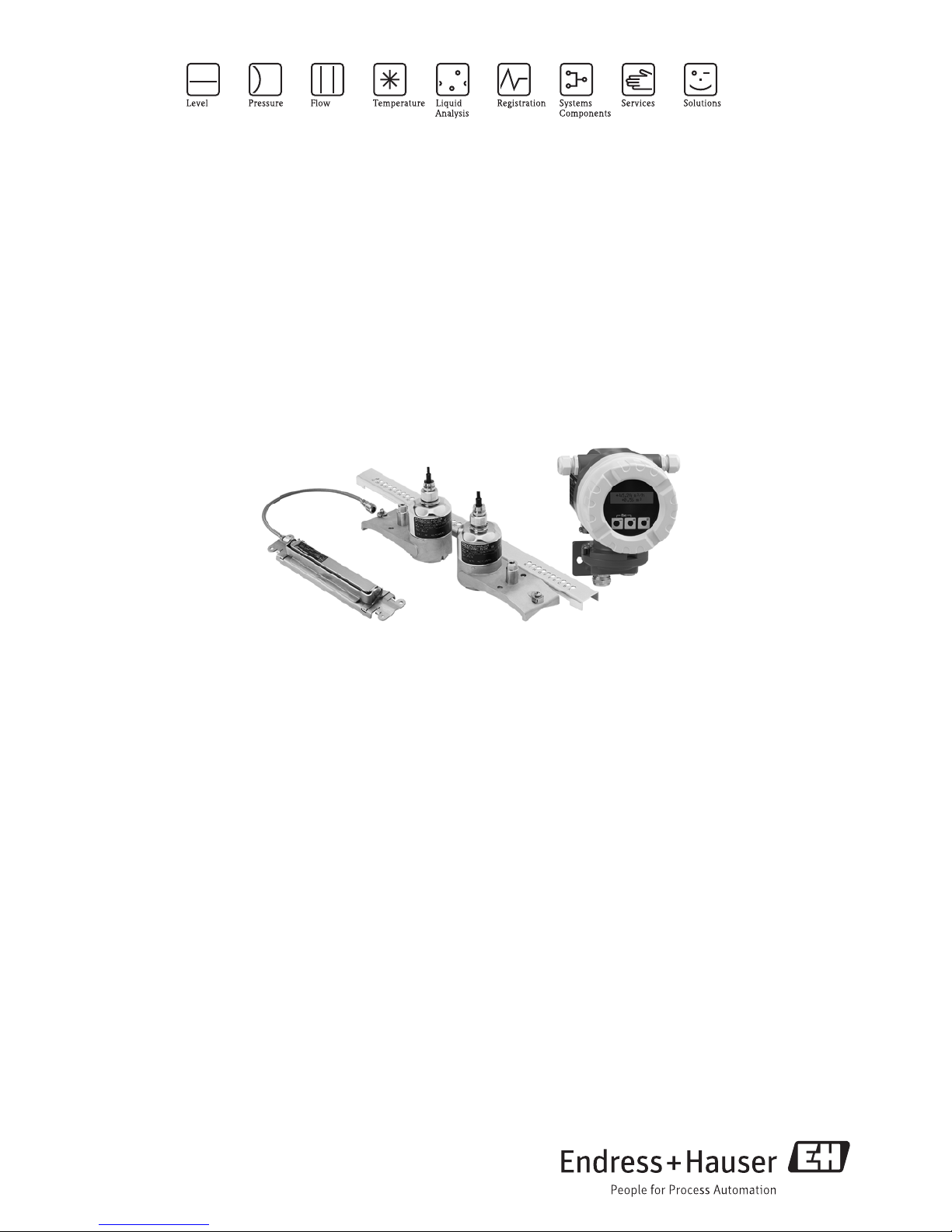
Measuring principle The measuring system operates on the principle of transit time difference. In this measurement method,
acoustic (ultrasonic) signals are transmitted between two sensors. The signals are sent in both directions,
i.e. the sensor in question works as both a sound transmitter and a sound receiver.
As the propagation velocity of the waves is less when the waves travel against the direction of flow than along
the direction of flow, a transit time difference occurs. This transit time difference is directly proportional to the
flow velocity.
A0013117
Principle of the transit time difference measurement method
Q = v · A
aSensor
bSensor
Q Volume flow
v Flow velocity (v & t )
t Transit time difference (t = t
a
– tb)
A Pipe cross-sectional area
The measuring system calculates the volume flow of the fluid from the measured transit time difference and
the pipe cross-sectional area. In addition to measuring the transit time difference, the system simultaneously
measures the sound velocity of the fluid. This additional measured variable can be used to distinguish different
fluids or as a measure of product quality.
The measuring device can be configured onsite to suit the specific application using Quick Setup menus.
b
Q
t
a
a
t
b
Proline Prosonic Flow 91W
4 Endress+Hauser
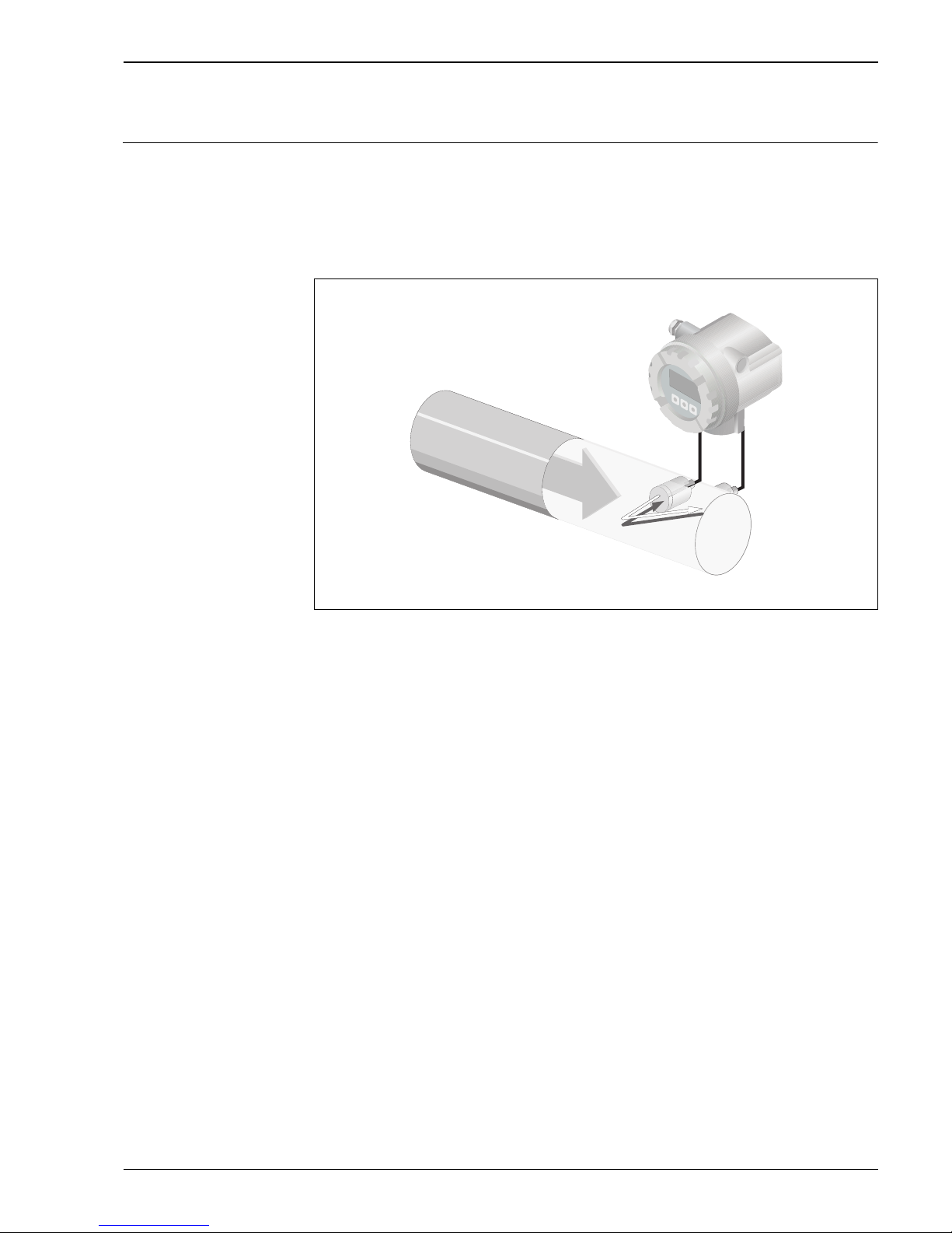
Measuring The measuring system consists of one transmitter and two sensors. Different versions are available depending
on the specific requirements.
The transmitter is used both to control the sensors and to prepare, process and evaluate the measuring signals,
and to convert the signals to a desired output variable.
The sensors work as sound transmitters and sound receivers. Depending on the application and version, the
sensors can be arranged for measurement via one or two traverses ä 5.
Transmitter
Mounting accessories
The requisite mounting distances must be determined for the sensors. Information on the fluid, the pipe
material used and the exact pipe dimensions is needed to determine these values. The values for the sound
velocity of the following fluids, pipe materials and lining materials are stored in the transmitter:
Prosonic Flow 91 W Field Housing
A0006022
Prosonic Flow W Prosonic Flow W
DN 15 to 65 (½" to 2½")
A0011484
DN 50 to 4000 (2" to 160")
A0013475
Fluid Pipe material Lining
•Water
•Sea water
• Distilled water
• Ammonia
• Alcohol
•Benzene
•Bromide
•Ethanol
•Glycol
•Kerosene
• Milk
• Methanol
• Toluene
•Lube oil
•Fuel Oil
•Petrol
• Carbon steel
• Ductile Iron
• Stainless steel
• Alloy C
•PVC
•PE
•LDPE
•HDPE
•PVDF
•PA
•PP
•PTFE
• Glass pyrex
•Mortar
• Rubber
• Tar Epoxy
Esc
Proline Prosonic Flow 91W
Endress+Hauser 5
Sensor selection and
arrangement
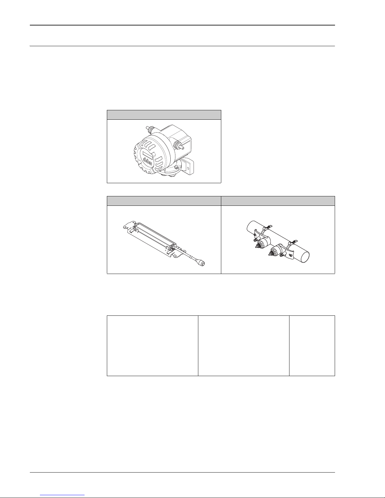
The sensors can be arranged in two ways:
• Mounting arrangement for measurement via one traverse:
the sensors are located on opposite sides of the pipe.
• Mounting arrangement for measurement via two traverses:
the sensors are located on the same side of the pipe.
A0005728
Sensor mounting arrangement (top view)
1 Mounting arrangement for measurement via one traverse
2 Mounting arrangement for measurement via two traverses
Recommendations
The number of traverses required depends on the sensor type, the nominal diameter and the thickness of the
pipe wall. We recommend the following types of mounting:
12
Sensor Type Nominal Diameter Sensor Frequency Sensor ID Type of Mounting
1)
Prosonic Flow W
DN 15 to 65 (½" to 2 ½") 6 MHz W-CL-6F 2 traverses
3)
DN 80 (3") 2 MHz W-CL-2F 2 traverses
DN 100 to 300 (4" to 12") 2 MHz (or 1 MHz)
W-CL-2F
W-CL-1F
2 traverses
2)
DN 300 to 600 (12" to 24") 1 MHz (or 2 MHz)
W-CL-1F
W-CL-2F
2 traverses
2)
DN 650 to 2000 (26" to 80") 1 MHz (or 0.5 MHz)
W-CL-1F
W-CL-05F
1 traverse
2)
1)
The installation of clamp-on sensors is principally recommended in the 2 traverse type installation. This type of
installation allows the easiest and most comfortable type of mounting. However, in certain applications a 1 traverse
installation may be preferred:
• Certain plastic pipes with wall thickness > 4 mm (0.16 in)
• Lined pipes
• Applications with fluids with high acoustic damping
2)
0.5 MHz sensors are also recommended for applications with composite material pipes such as GRP and may be
recommended for certain lined pipes, pipes with wall thickness >10 mm (0.4 in), or applications with media with
high acoustic damping. In addition, for these applications we principally recommend mounting the W sensors in
a 1 traverse configuration.
3)
6 MHz sensors are recommended for applications where flow velocity is< 10 m/s (32.8 Hz/s)

Proline Prosonic Flow 91W
6 Endress+Hauser
Input
Measured variable Flow velocity (differential delay proportional to flow velocity)
Measuring range Typically v = 0 to 15 m/s (0 to 50 ft/s) at the specified measuring accuracy
Operable flow range Over 150 : 1
Output
Output signal Current output:
• Galvanically isolated
• Full scale value adjustable
• Temperature coefficient: typ. 2 μA/°C, resolution: 1.5 μA
• Active: 4 to 20 mA, R
L
< 700 (for HART: RL 250 )
Pulse/status output:
• Galvanically isolated
• Open collector
• 30 V DC / 250 mA
• Passive
• Can be configured as:
– Pulse output: pulse value and pulse polarity can be selected, max. pulse width adjustable (5 to 2000 ms),
pulse frequency max. 100 Hz
– Status output: for example, can be configured for error messages, empty pipe detection, flow recognition,
limit value
Signal on alarm • Current output failsafe mode selectable.
• Pulse/frequency output failsafe mode selectable
Load See “Output signal”
Low flow cutoff Switching point for the low flow freely selectable.
Galvanic isolation All circuits for inputs, outputs, and power supply are galvanically isolated from each other.
Proline Prosonic Flow 91W
Endress+Hauser 7
Power supply
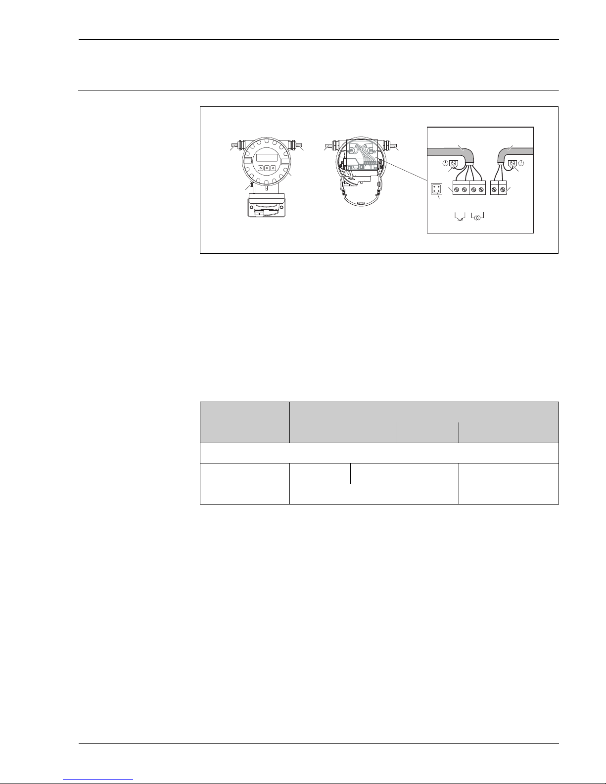
Measuring unit electrical
connection
a0005838
Connecting the transmitter (Aluminium-Fieldhousing).
cable cross-section: max. 2.5 mm
(AWG 13)
aCover
b Cable for power supply: 85 to 260 V AC, 20 to 55 V AC, 16 to 62 V DC
c Terminal for power supply:
d Terminal for power supply: Nr. 1–2 (terminal assignment)
e Signal cable
f Ground terminal für signal cable
g Terminal connector for signal cable: Nr. 24–27 (terminal assignment)
h Service connector
i Ground terminal for potential matching
Terminal assignment Prosonic Flow 91W
eb
2127
–
25–26
+
24
+
L1
(L+)
N
(L-)
e
g
b
d
h
c
f
b
a
e
i
Order variant Terminal No. (inputs/outputs)
24 (+)/25 (–) 26 (+)/27 (–) 1 (L1/L+) /2 (N/L–)
Fixed communication boards (fixed assignment)
91***-***********A Pulse output HART current output Power supply
Functional values see "Output signal" see "supply voltage"
Proline Prosonic Flow 91W
8 Endress+Hauser
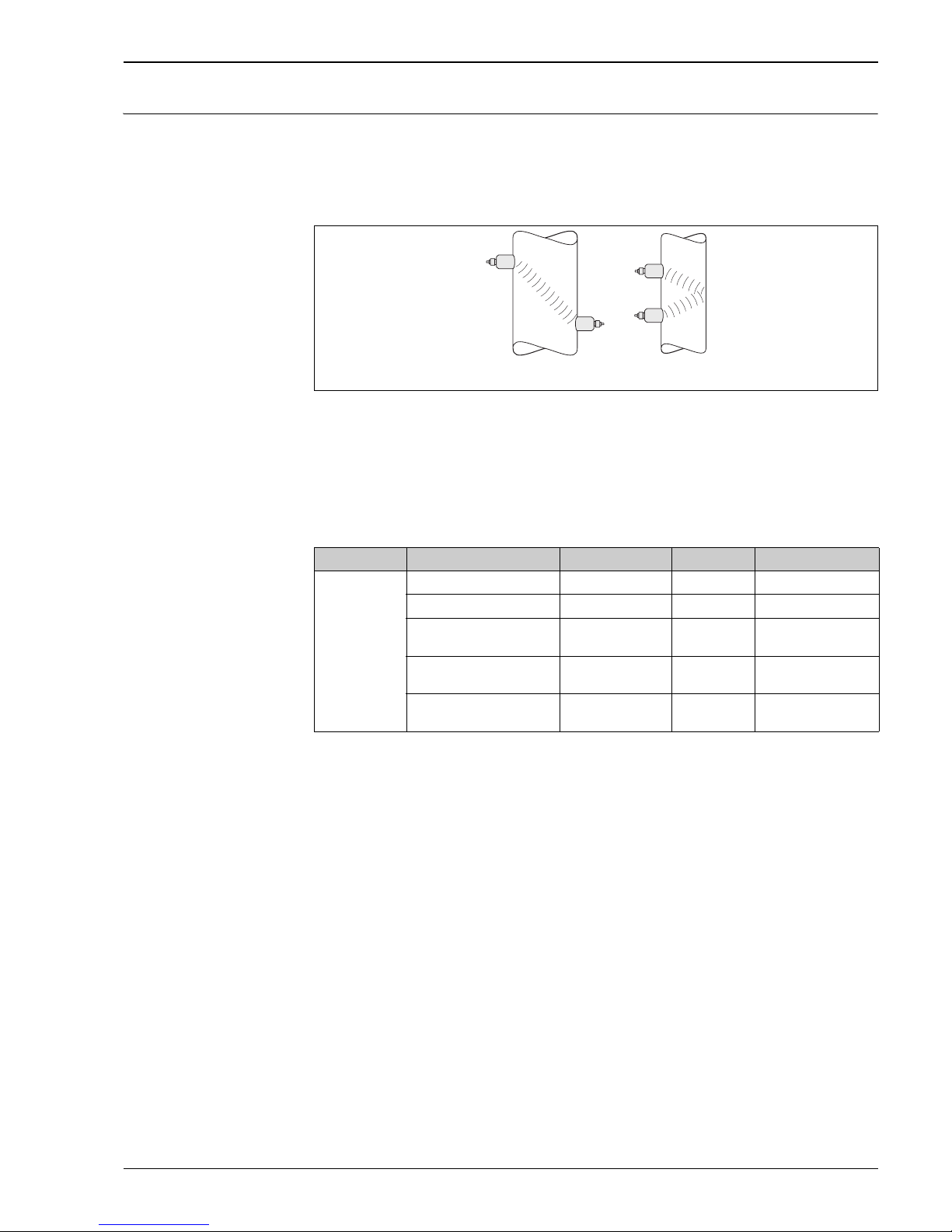
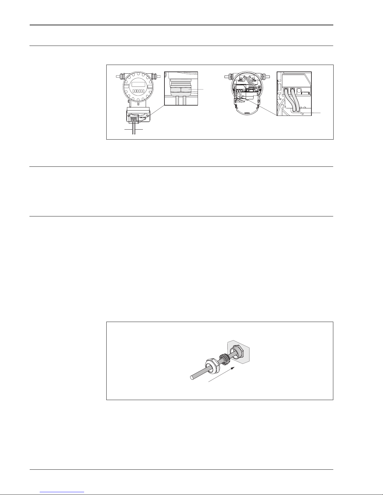
Connecting the connecting
cable
Connection sensor cable in the electronics compartment
A0015907
a, b Sensor connection cable
c Cable gland holder
d Cable gland
Supply voltage Transmitter
85 to 260 V AC, 45 to 65 Hz
20 to 55 V AC, 45 to 65 Hz
16 to 62 V DC
Sensor
Powered by the transmitter
Cable entry Power supply and signal cables (inputs/outputs)
• Cable entry M20 × 1.5 (8 to 12 mm; 0.31 to 0.47 in)
• Cable gland for cables, 6 to 12 mm ( 0.24" to 0.47")
• Thread for cable entries ½" NPT, G ½"
Connection cable (sensor /transmitter)
Cable glands for one multicore connection cable (1 ×
8 mm) per cable entry
• Cable gland M20 × 1.5
• Thread for cable entries ½" NPT, G ½"
Connection cable (sensor /transmitter)
Cable glands for two single core connection cable (2 ×
4 mm) per cable entry
• Cable gland M20 × 1.5
• Thread for cable entries ½" NPT, G ½"
The Prosonic Flow W DN 15 to 65 (½ to 2½") is grounded via the cable gland.
a0016008
Cable gland for one multicore connection cable (1 ×8 mm /0.31 in) per cable entry
ab
d
c
 Loading...