

Endress+Hauser Proline Promass P 300, Proline Promass S 300, Proline Promass Q 300 User Manual
Page 1
TI01276D/06/EN/04.18
71415042
2018-11-01
Products Solutions Services
Technical Information
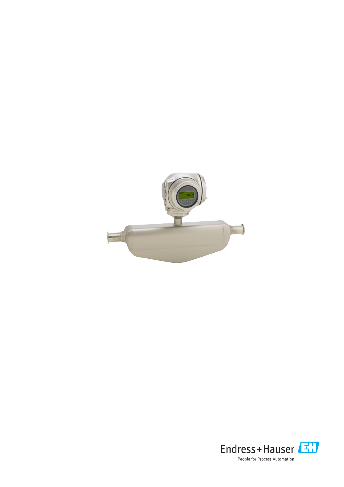
Proline Promass P 300
Coriolis flowmeter
The specialist for life sciences with a compact, easily accessible transmitter
Application
• Measuring principle operates independently of physical fluid
properties such as viscosity or density
• Dedicated to applications under sterile conditions in the life
sciences industry
Device properties
• ASME BPE, 3-A, EHEDG conform & low delta-ferrite
• Electropolished measuring tube in 1.4435 (316L)
• Fast recovery from CIP/SIP
• Compact hygienic dual-compartment housing with IP69 and
up to 3 I/Os
• Backlit display with touch control and WLAN access
• Remote display available
Your benefits
• Highest process quality – fully compliant with
industry requirements
• Fewer process measuring points – multivariable
measurement (flow, density, temperature)
• Space‐saving installation – no inlet/outlet run needs
• Full access to process and diagnostic information –
numerous, freely combinable I/Os and fieldbuses
• Reduced complexity and variety – freely configurable I/O
functionality
• Integrated verification – Heartbeat Technology
Page 2

Table of contents
Proline Promass P 300
About this document ........................ 4
Symbols used ................................ 4
Function and system design ................... 5
Measuring principle ............................ 5
Measuring system ............................. 6
Equipment architecture ......................... 7
Safety ..................................... 7
Input .................................... 10
Measured variable ............................ 10
Measuring range ............................. 10
Operable flow range ........................... 10
Input signal ................................ 10
Output .................................. 12
Output and input variants ....................... 12
Output signal ............................... 13
Signal on alarm .............................. 17
Ex connection data ........................... 19
Low flow cut off ............................. 20
Galvanic isolation ............................ 20
Protocol-specific data .......................... 20
Power supply ............................. 25
Terminal assignment .......................... 25
Device plugs available .......................... 26
Pin assignment, device plug ...................... 27
Supply voltage .............................. 28
Power consumption ........................... 29
Current consumption .......................... 29
Power supply failure .......................... 29
Electrical connection .......................... 30
Potential equalization ......................... 39
terminals .................................. 39
Cable entries ............................... 39
Cable specification ............................ 39
Climate class ............................... 49
Degree of protection .......................... 49
Vibration resistance ........................... 49
Shock resistance ............................. 49
Shock resistance ............................. 50
Interior cleaning ............................. 50
Electromagnetic compatibility (EMC) ............... 50
Process .................................. 50
Medium temperature range ...................... 50
Density ................................... 51
Pressure-temperature ratings .................... 51
Sensor housing .............................. 54
Flow limit ................................. 55
Pressure loss ............................... 55
System pressure ............................. 55
Thermal insulation ........................... 55
Heating ................................... 56
Vibrations ................................. 56
Mechanical construction .................... 57
Dimensions in SI units ......................... 57
Dimensions in US units ......................... 78
Weight ................................... 86
Materials .................................. 86
Process connections ........................... 89
Surface roughness ........................... 89
Operability ............................... 89
Operating concept ............................ 89
Languages ................................. 90
Local operation .............................. 90
Remote operation ............................ 91
Service interface ............................. 97
Network integration .......................... 98
Supported operating tools ....................... 99
HistoROM data management .................... 100
Performance characteristics .................. 42
Reference operating conditions ................... 42
Maximum measured error ....................... 42
Repeatability ............................... 43
Response time .............................. 43
Influence of ambient temperature ................. 43
Influence of medium temperature .................. 44
Influence of medium pressure .................... 44
Design fundamentals .......................... 45
Installation ............................... 45
Mounting location ............................ 46
Orientation ................................ 46
Inlet and outlet runs .......................... 47
Special mounting instructions .................... 47
Environment .............................. 49
Ambient temperature range ..................... 49
Storage temperature .......................... 49
Certificates and approvals .................. 101
CE mark .................................. 101
C-Tick symbol .............................. 101
Ex approval ............................... 101
Sanitary compatibility ......................... 103
Pharmaceutical compatibility .................... 103
Functional safety ............................ 103
HART certification ........................... 103
FOUNDATION Fieldbus certification ............... 103
Certification PROFIBUS ........................ 103
EtherNet/IP certification ....................... 103
Certification PROFINET ........................ 103
Pressure Equipment Directive ................... 104
Radio approval ............................. 104
Additional certification ........................ 104
Other standards and guidelines .................. 104
Ordering information ...................... 105
2 Endress+Hauser
Page 3

Proline Promass P 300
Application packages ...................... 105
Diagnostics functions ......................... 105
Heartbeat Technology ........................ 106
Concentration .............................. 106
Special density ............................. 106
OPC-UA server ............................. 106
Accessories .............................. 106
Device-specific accessories ...................... 107
Communication-specific accessories ............... 108
Service-specific accessories ..................... 109
System components .......................... 109
Supplementary documentation .............. 110
Standard documentation ....................... 110
Device-dependent additional documentation ......... 110
Registered trademarks ..................... 111
Endress+Hauser 3
Page 4

About this document
A
Symbols used Electrical symbols
Symbol Meaning
Proline Promass P 300
Direct current
Alternating current
Direct current and alternating current
Ground connection
A grounded terminal which, as far as the operator is concerned, is grounded via a
grounding system.
Protective Earth (PE)
A terminal which must be connected to ground prior to establishing any other
connections.
The ground terminals are situated inside and outside the device:
• Inner ground terminal: Connects the protectiv earth to the mains supply.
• Outer ground terminal: Connects the device to the plant grounding system.
Communication symbols
Symbol Meaning
Wireless Local Area Network (WLAN)
Communication via a wireless, local network.
LED
Light emitting diode is off.
LED
Light emitting diode is on.
LED
Light emitting diode is flashing.
Symbols for certain types of information
Symbol Meaning
Permitted
Procedures, processes or actions that are permitted.
Preferred
Procedures, processes or actions that are preferred.
Forbidden
Procedures, processes or actions that are forbidden.
Tip
Indicates additional information.
Reference to documentation.
Reference to page.
Reference to graphic.
Visual inspection.
4 Endress+Hauser
Page 5
Proline Promass P 300
1.
-
.
2
1
3
Symbols in graphics
Symbol Meaning
1, 2, 3, ... Item numbers
, 2., 3., … Series of steps
A, B, C, ... Views
A-A, B-B, C-C, ... Sections
Hazardous area
Safe area (non-hazardous area)
Flow direction
Function and system design
Measuring principle
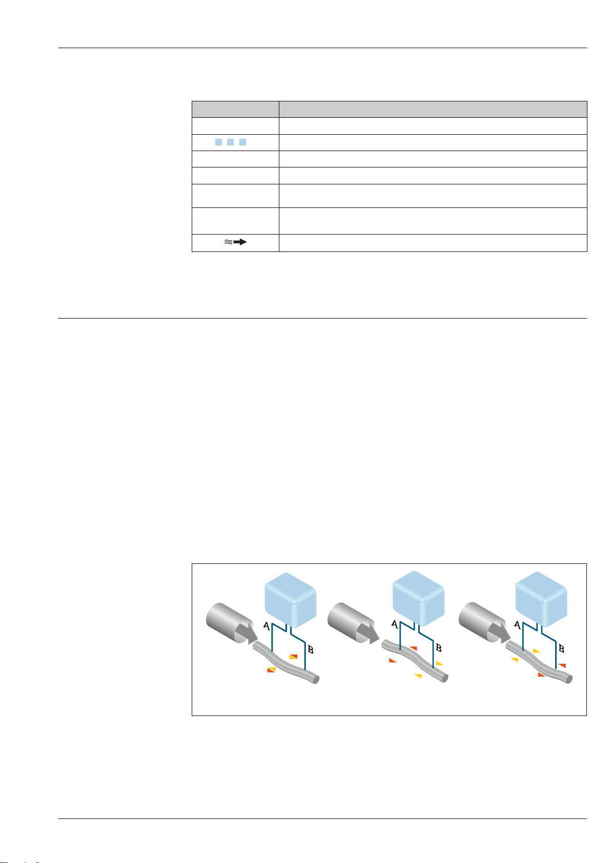
The measuring principle is based on the controlled generation of Coriolis forces. These forces are
always present in a system when both translational and rotational movements are superimposed.
Fc = 2 · ∆m (ν · ω)
Fc = Coriolis force
∆m = moving mass
ω = rotational velocity
ν = radial velocity in rotating or oscillating system
The amplitude of the Coriolis force depends on the moving mass ∆m, its velocity ν in the system and
thus on the mass flow. Instead of a constant rotational velocity ω, the sensor uses oscillation.
In the sensor, an oscillation is produced in the measuring tube. The Coriolis forces produced at the
measuring tube cause a phase shift in the tube oscillations (see illustration):
• If there is zero flow (i.e. when the fluid stands still), the oscillation measured at points A and B has
the same phase (no phase difference) (1).
• Mass flow causes deceleration of the oscillation at the inlet of the tubes (2) and acceleration at the
outlet (3).
A0029932
The phase difference (A-B) increases with increasing mass flow. Electrodynamic sensors register the
tube oscillations at the inlet and outlet. System balance is created by exciting an eccentrically
arranged swinging mass to antiphase oscillation. The measuring principle operates independently of
temperature, pressure, viscosity, conductivity and flow profile.
Endress+Hauser 5
Page 6
Proline Promass P 300
Density measurement
The measuring tube is continuously excited at its resonance frequency. A change in the mass and
thus the density of the oscillating system (comprising measuring tube and fluid) results in a
corresponding, automatic adjustment in the oscillation frequency. Resonance frequency is thus a
function of medium density. The microprocessor utilizes this relationship to obtain a density signal.
Volume measurement
Together with the measured mass flow, this is used to calculate the volume flow.
Temperature measurement
The temperature of the measuring tube is determined in order to calculate the compensation factor
due to temperature effects. This signal corresponds to the process temperature and is also available
as an output signal.
Measuring system
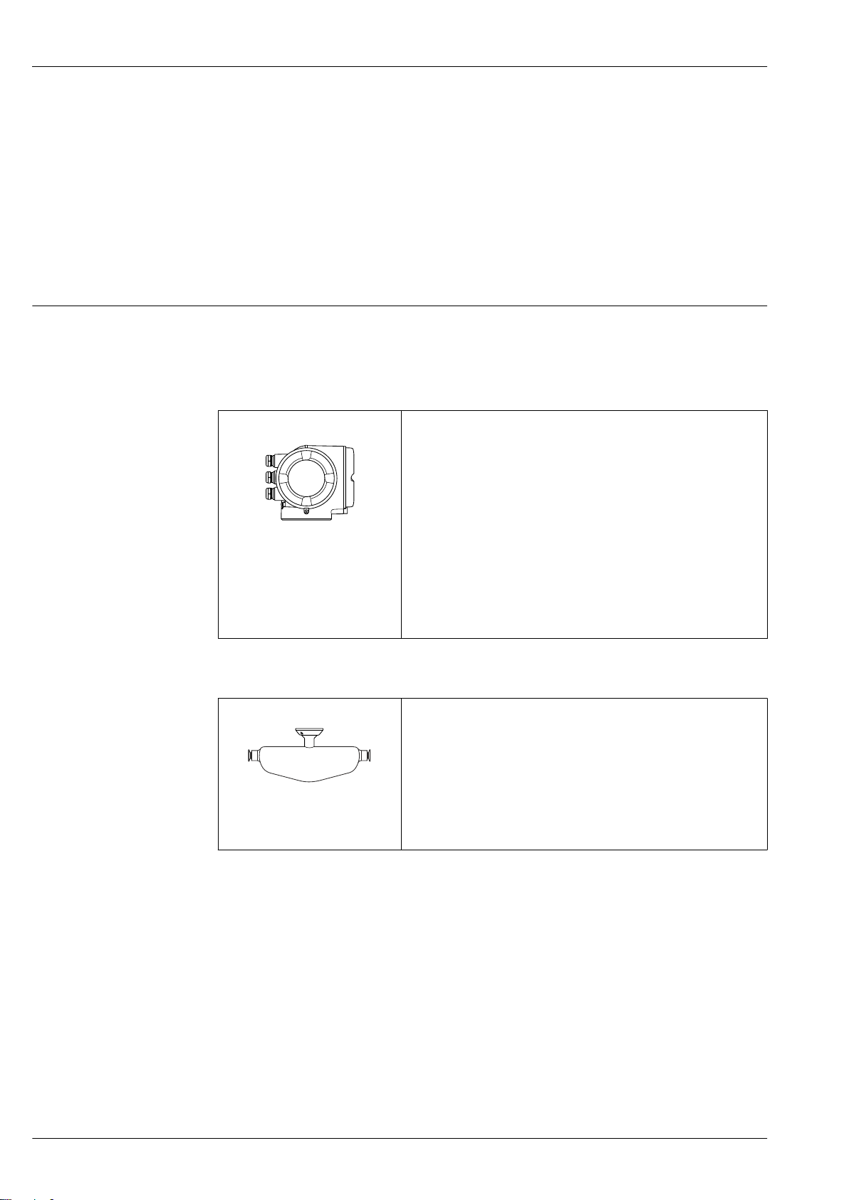
The device consists of a transmitter and a sensor.
The device is available as a compact version:
The transmitter and sensor form a mechanical unit.
Transmitter
Promass 300
Device versions and materials:
• Transmitter housing
– Aluminum, coated: aluminum, AlSi10Mg, coated
– Stainless, hygienic: stainless steel, 1.4404
• Material of window in transmitter housing:
– Aluminum, coated: glass
– Stainless, hygienic: polycarbonate
Configuration:
A0026708
• External operation via 4-line, backlit, graphic local display with touch
control and guided menus ("Make-it-run" wizards) for applicationspecific commissioning.
• Via service interface or WLAN interface:
– Operating tools (e.g. FieldCare, DeviceCare, SmartBlue app)
– Web server (access via Web browser, e.g. Microsoft Internet
Explorer, Microsoft Edge)
Sensor
Promass P • For use in sterile applications in heavily regulated industries
• Nominal diameter range: DN 8 to 50 (³⁄₈ to 2")
• Materials:
– Sensor: stainless steel, 1.4301 (304)
– Measuring tubes: stainless steel, 1.4435 BN2 (316L)
A0026710
– Process connections: stainless steel, 1.4435 BN2 (316L); 1.4404
(316/316L)
– Surface quality: Ra
Ra
0.38 µm (15 µin) (electropolished)
max
– Delta ferrite <1%
0.76 µm (30 µin)
max
6 Endress+Hauser
Page 7
Proline Promass P 300
2
1
6
5
7
4
3
3
Equipment architecture
A0027512
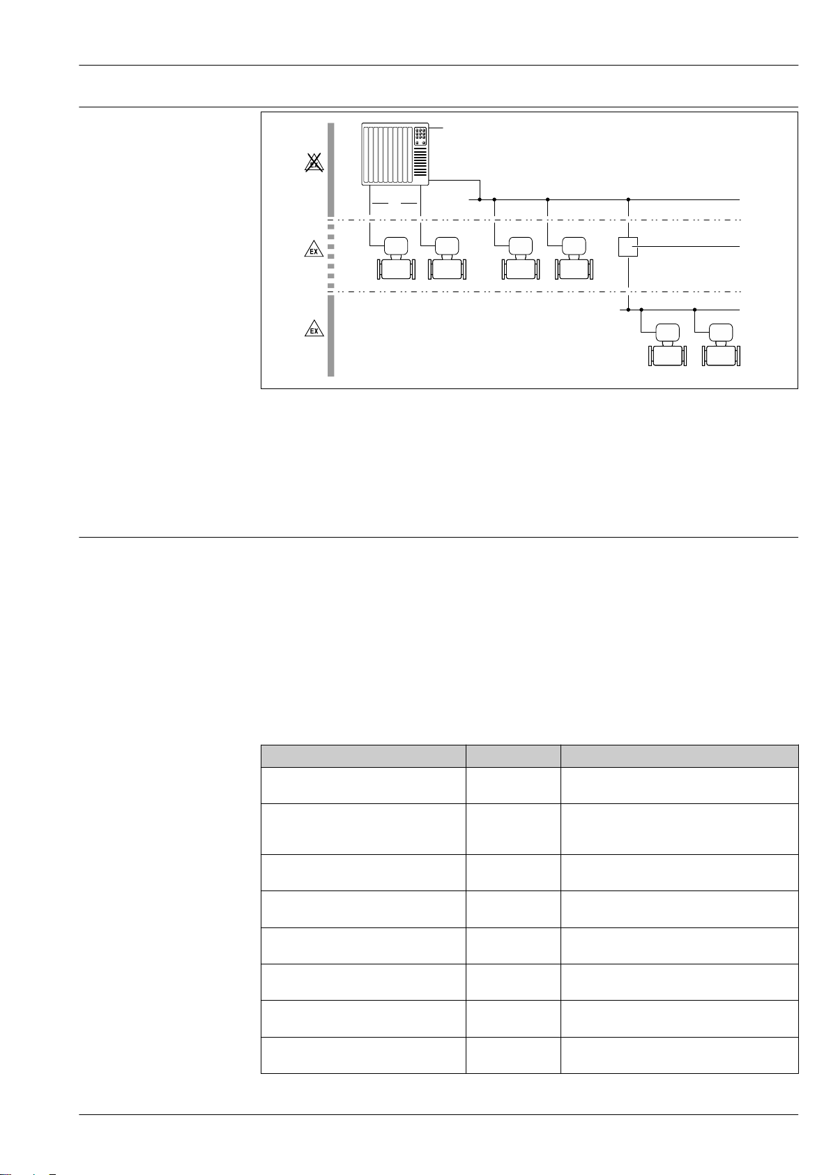
1 Possibilities for integrating measuring devices into a system
1 Control system (e.g. PLC)
2 Connecting cable (0/4 to 20 mA HART etc.)
3 Fieldbus
4 Segment coupler
5 Non-hazardous area
6 Hazardous area: Zone 2; Class I, Division 2
7 Hazardous area: Zone 1; Class I, Division 1
Safety IT security
Our warranty is valid only if the device is installed and used as described in the Operating
Instructions. The device is equipped with security mechanisms to protect it against any inadvertent
changes to the settings.
IT security measures, which provide additional protection for the device and associated data transfer,
must be implemented by the operators themselves in line with their security standards.
Device-specific IT security
The device offers a range of specific functions to support protective measures on the operator's side.
These functions can be configured by the user and guarantee greater in-operation safety if used
correctly. An overview of the most important functions is provided in the following section.
Function/interface Factory setting Recommendation
Write protection via hardware write
protection switch → 8
Access code
(also applies for Web server login or
FieldCare connection) → 8
WLAN
(order option in display module)
WLAN security mode Enabled (WPA2-
WLAN passphrase
(password) → 8
WLAN mode Access Point On an individual basis following risk
Web server→ 8 Enabled. On an individual basis following risk
CDI-RJ45 service interface → 9 – On an individual basis following risk
Not enabled. On an individual basis following risk
assessment.
Not enabled
(0000).
Enabled. On an individual basis following risk
PSK)
Serial number Assign a customized access code during
Assign a customized access code during
commissioning.
assessment.
Do not change.
commissioning.
assessment.
assessment.
assessment.
Endress+Hauser 7
Page 8
Proline Promass P 300
Protecting access via hardware write protection
Write access to the device parameters via the local display, Web browser or operating tool (e.g.
FieldCare, DeviceCare) can be disabled via a write protection switch (DIP switch on the
motherboard). When hardware write protection is enabled, only read access to the parameters is
possible.
Hardware write protection is disabled when the device is delivered.
Protecting access via a password
Different passwords are available to protect write access to the device parameters or access to the
device via the WLAN interface.
• User-specific access code
Protect write access to the device parameters via the local display, Web browser or operating tool
(e.g. FieldCare, DeviceCare). Access authorization is clearly regulated through the use of a userspecific access code.
• WLAN passphrase
The network key protects a connection between an operating unit (e.g. notebook or tablet) and the
device via the WLAN interface which can be ordered as an option.
• Infrastructure mode
When the device is operated in infrastructure mode, the WLAN passphrase corresponds to the
WLAN passphrase configured on the operator side.
User-specific access code
Write access to the device parameters via the local display, Web browser or operating tool (e.g.
FieldCare, DeviceCare) can be protected by the modifiable, user-specific access code.
WLAN passphrase: Operation as WLAN access point
A connection between an operating unit (e.g. notebook or tablet) and the device via the WLAN
interface, which can be ordered as an optional extra, is protected by the network key. The WLAN
authentication of the network key complies with the IEEE 802.11 standard.
When the device is delivered, the network key is pre-defined depending on the device. It can be
changed via the WLAN settings submenu in the WLAN passphrase parameter.
Infrastructure mode
A connection between the device and WLAN access point is protected by means of an SSID and
passphrase on the system side. Please contact the relevant system administrator for access.
General notes on the use of passwords
• The access code and network key supplied with the device should be changed during
commissioning.
• Follow the general rules for generating a secure password when defining and managing the access
code or network key.
• The user is responsible for the management and careful handling of the access code and network
key.
Access via Web server
The device can be operated and configured via a Web browser with the integrated Web server. The
connection is via the service interface (CDI-RJ45) or the WLAN interface. For device versions with
the EtherNet/IP and PROFINET communication protocols, the connection can also be established via
the terminal connection for signal transmission with EtherNet/IP or PROFINET (RJ45 connector).
The Web server is enabled when the device is delivered. The Web server can be disabled if necessary
(e.g. after commissioning) via the Web server functionality parameter.
The device and status information can be hidden on the login page. This prevents unauthorized
access to the information.
For detailed information on device parameters, see:
The "Description of Device Parameters" document → 110
Access via OPC-UA
The "OPC UA Server" application package is available in the device version with the HART
communication protocol → 106.
8 Endress+Hauser
Page 9

Proline Promass P 300
The device can communicate with OPC UA clients using the "OPC UA Server" application package.
The OPC UA server integrated in the device can be accessed via the WLAN access point using the
WLAN interface - which can be ordered as an optional extra - or the service interface (CDI- RJ45) via
Ethernet network. Access rights and authorization as per separate configuration.
The following Security Modes are supported as per the OPC UA Specification (IEC 62541):
• None
• Basic128Rsa15 – signed
• Basic128Rsa15 – signed and encrypted
Access via service interface (CDI-RJ45)
The device can be connected to a network via the service interface (CDI-RJ45). Device-specific
functions guarantee the secure operation of the device in a network.
The use of relevant industrial standards and guidelines that have been defined by national and
international safety committees, such as IEC/ISA62443 or the IEEE, is recommended. This includes
organizational security measures such as the assignment of access authorization as well as technical
measures such as network segmentation.
The device can be integrated in a ring topology. The device is integrated via the terminal
connection for signal transmission (output 1) and the connection to the service interface (CDIRJ45) → 95.
Endress+Hauser 9
Page 10
Input
Measured variable Direct measured variables
• Mass flow
• Density
• Temperature
Calculated measured variables
• Volume flow
• Corrected volume flow
• Reference density
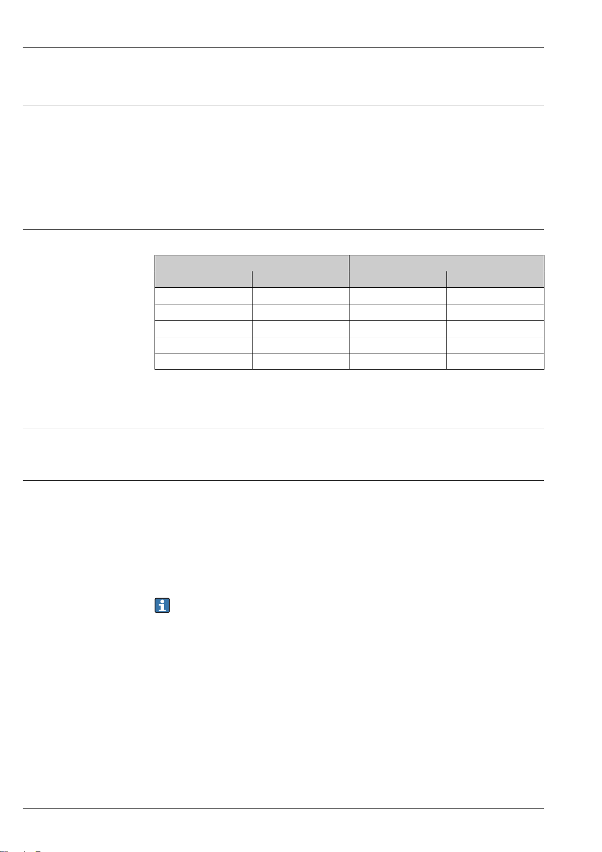
Measuring range Measuring range for liquids
Proline Promass P 300
DN Measuring range full scale values
[mm] [in] [kg/h] [lb/min]
8 ³⁄₈ 0 to 2 000 0 to 73.50
15 ½ 0 to 6 500 0 to 238.9
25 1 0 to 18 000 0 to 661.5
40 1½ 0 to 45 000 0 to 1 654
50 2 0 to 70 000 0 to 2 573
Recommended measuring range
"Flow limit" section → 55
Operable flow range
Over 1000 : 1.
Flow rates above the preset full scale value do not override the electronics unit, with the result that
the totalizer values are registered correctly.
Input signal Input and output versions
→ 12
External measured values
To increase the accuracy of certain measured variables, the automation system can continuously
write various measured values to the measuring device:
• Operating pressure to increase accuracy (Endress+Hauser recommends the use of a pressure
measuring device for absolute pressure, e.g. Cerabar M or Cerabar S)
• Medium temperature to increase accuracy (e.g. iTEMP)
Various pressure transmitters and temperature measuring devices can be ordered from Endress
+Hauser: see "Accessories" section → 109
min(F)
to
max(F)
HART protocol
The measured values are written from the automation system to the measuring device via the HART
protocol. The pressure transmitter must support the following protocol-specific functions:
• HART protocol
• Burst mode
Current input
The measured values are written from the automation system to the measuring device via the
current input → 11.
10 Endress+Hauser
Page 11
Proline Promass P 300
Digital communication
The measured values can be written from the automation system to the measuring via:
• FOUNDATION Fieldbus
• PROFIBUS DP
• PROFIBUS PA
• Modbus RS485
• EtherNet/IP
• PROFINET
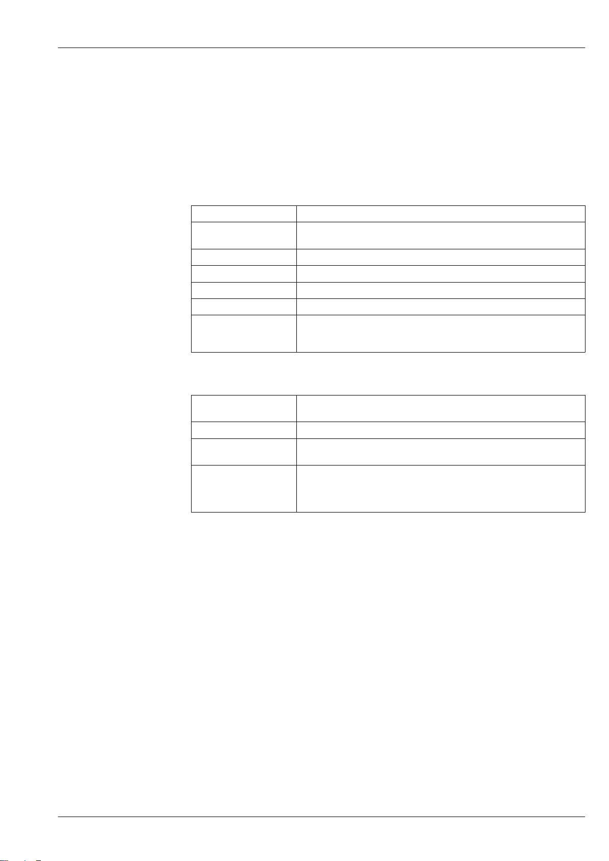
Current input 0/4 to 20 mA
Current input 0/4 to 20 mA (active/passive)
Current span • 4 to 20 mA (active)
• 0/4 to 20 mA (passive)
Resolution 1 µA
Voltage drop Typically: 0.6 to 2 V for 3.6 to 22 mA (passive)
Maximum input voltage ≤ 30 V (passive)
Open-circuit voltage ≤ 28.8 V (active)
Possible input variables • Pressure
• Temperature
• Density
Status input
Maximum input values • DC –3 to 30 V
• If status input is active (ON): Ri >3 kΩ
Response time Adjustable: 5 to 200 ms
Input signal level • Low signal: DC –3 to +5 V
• High signal: DC 12 to 30 V
Assignable functions • Off
• Reset the individual totalizers separately
• Reset all totalizers
• Flow override
Endress+Hauser 11
Page 12
Output
Proline Promass P 300
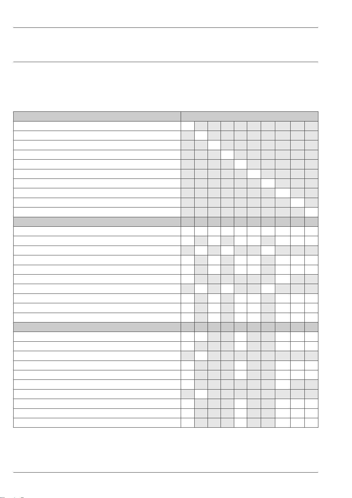
Output and input variants
Depending on the option selected for output/input 1, different options are available for the other
outputs and inputs. Only one option can be selected for each output/input 1 to 3. The table must be
read vertically (↓).
Example: If the option BA "4–20 mA HART" was selected for output/input 1, one of the options A, B,
D, E, F, H, I or J is available for output 2 and one of the options A, B, D, E, F, H, I or J is available for
output 3.
Order code for "Output; input 1" (020) → Possible options
Current output 4 to 20 mA HART BA
Current output 4 to 20 mA HART Ex i ↓ CA
FOUNDATION Fieldbus ↓ SA
FOUNDATION Fieldbus Ex i ↓ TA
PROFIBUS DP ↓ LA
PROFIBUS PA ↓ GA
PROFIBUS PA Ex i ↓ HA
Modbus RS485 ↓ MA
EtherNet/IP 2-port switch integrated ↓ NA
PROFINET 2-port switch integrated ↓ RA
Order code for "Output; input 2" (021) → ↓ ↓ ↓ ↓ ↓ ↓ ↓ ↓ ↓ ↓
Not assigned A A A A A A A A A A
Current output 0/4 to 20 mA B B B B B B B
Current output 0/4 to 20 mA (Ex i) C C C
User configurable input/output
Pulse/frequency/switch output E E E E E E E
Double pulse output
Pulse/frequency/switch output (Ex i) G G G
Relay output H H H H H H H
Current input 0/4 to 20 mA I I I I I I I
Status input J J J J J J J
Order code for "Output; input 3" (022) → ↓ ↓ ↓ ↓ ↓ ↓ ↓ ↓ ↓ ↓
Not assigned A A A A A A A A A A
Current output 0/4 to 20 mA B B B B B
Current output 0/4 to 20 mA (Ex i) C
User configurable input/output D D D D D
Pulse/frequency/switch output E E E E E
Double pulse output (slave)
Pulse/frequency/switch output (Ex i) G
Relay output H H H H H
Current input 0/4 to 20 mA I I I I I
Status input J J J J J
2)
1)
2)
D D D D D D D
F F
F F
1) A specific input or output can be assigned to a user configurable input/output → 16.
2) If double pulse output (F) is selected for output/input 2 (021), only the double pulse output (F) option is available for selection for output/input 3
(022).
12 Endress+Hauser
Page 13
Proline Promass P 300
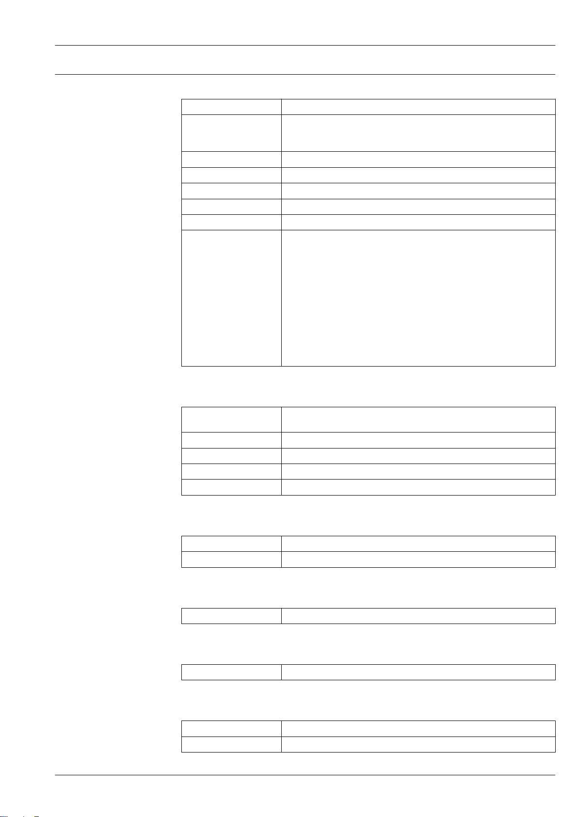
Output signal HART current output
Current output 4 to 20 mA HART
Current span Can be set to: 4 to 20 mA (active/passive)
Open-circuit voltage DC 28.8 V (active)
Maximum input voltage DC 30 V (passive)
Load 250 to 700 Ω
Resolution 0.38 µA
Damping Configurable: 0.07 to 999 s
Assignable measured
variables
Ex-i, passive
• Mass flow
• Volume flow
• Corrected volume flow
• Density
• Reference density
• Temperature
• Electronic temperature
• Oscillation frequency 0
• Oscillation damping 0
• Signal asymmetry
• Exciter current 0
The range of options increases if the measuring device has one or more
application packages.
PROFIBUS PA
PROFIBUS PA In accordance with EN 50170 Volume 2, IEC 61158-2 (MBP), galvanically
isolated
Data transmission 31.25 kbit/s
Current consumption 10 mA
Permitted supply voltage 9 to 32 V
Bus connection With integrated reverse polarity protection
PROFIBUS DP
Signal encoding NRZ code
Data transfer 9.6 kBaud…12 MBaud
EtherNet/IP
Standards In accordance with IEEE 802.3
PROFINET
Standards In accordance with IEEE 802.3
FOUNDATION Fieldbus
FOUNDATION Fieldbus H1, IEC 61158-2, galvanically isolated
Data transfer 31.25 kbit/s
Endress+Hauser 13
Page 14
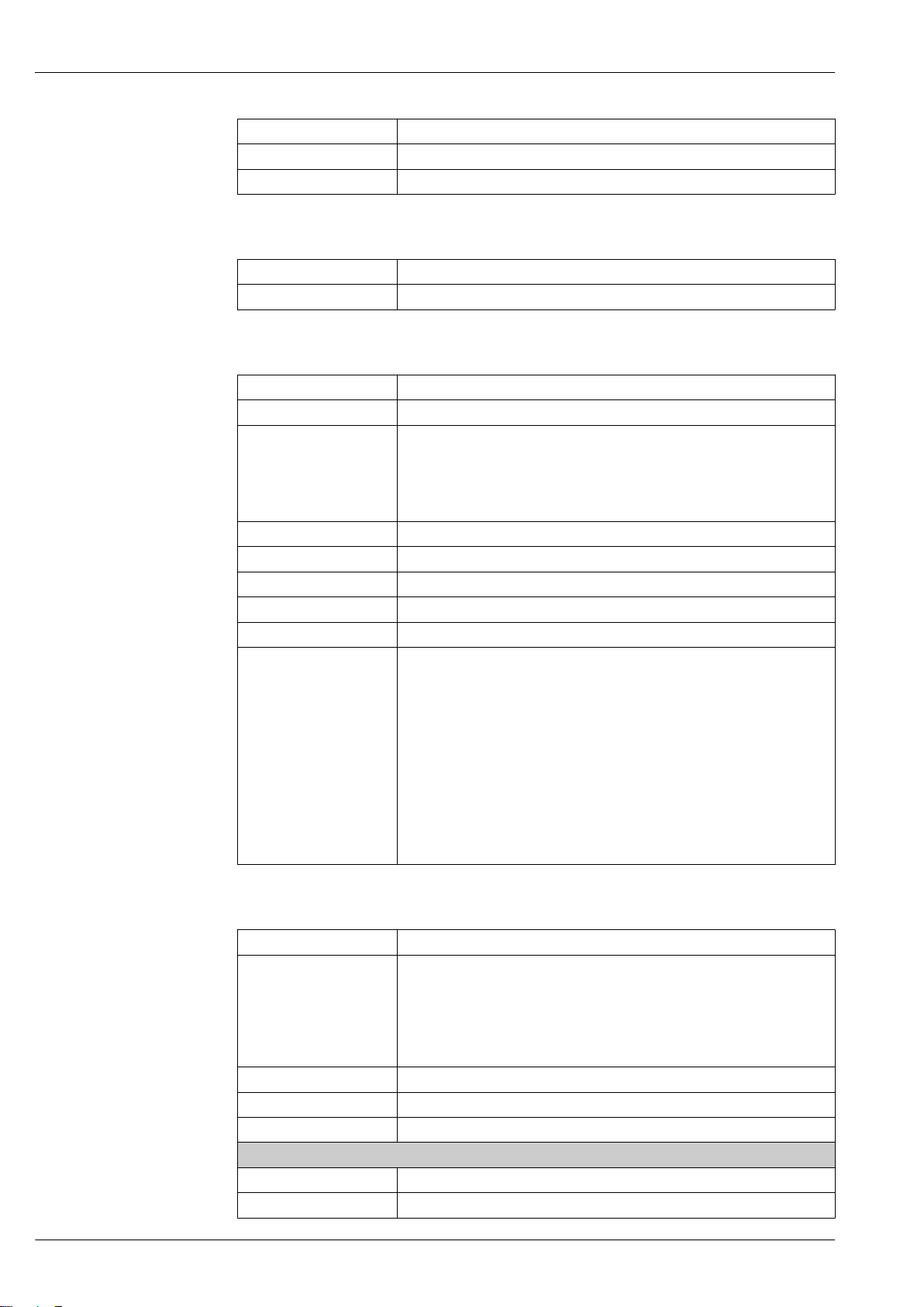
Current consumption 10 mA
Permitted supply voltage 9 to 32 V
Bus connection With integrated reverse polarity protection
Modbus RS485
Physical interface RS485 in accordance with EIA/TIA-485 standard
Terminating resistor Integrated, can be activated via DIP switches
Current output 0/4 to 20 mA
Current output 0/4 to 20 mA
Maximum output values 22.5 mA
Current span Can be set to:
• 4 to 20 mA (active)
• 0/4 to 20 mA (passive)
Ex-i, passive
Proline Promass P 300
Open-circuit voltage DC 28.8 V (active)
Maximum input voltage DC 30 V (passive)
Load 0 to 700 Ω
Resolution 0.38 µA
Damping Adjustable: 0.07 to 999 s
Assignable measured
variables
• Mass flow
• Volume flow
• Corrected volume flow
• Density
• Reference density
• Temperature
• Electronic temperature
• Oscillation frequency 0
• Oscillation damping 0
• Signal asymmetry
• Exciter current 0
The range of options increases if the measuring device has one or more
application packages.
Pulse/frequency/switch output
Function Can be set to pulse, frequency or switch output
Version Open collector
Can be set to:
• Active
• Passive
Ex-i, passive
Maximum input values DC 30 V, 250 mA (passive)
Open-circuit voltage DC 28.8 V (active)
Voltage drop For 22.5 mA: ≤ DC 2 V
Pulse output
Maximum input values DC 30 V, 250 mA (passive)
Maximum output current 22.5 mA (active)
14 Endress+Hauser
Page 15
Proline Promass P 300
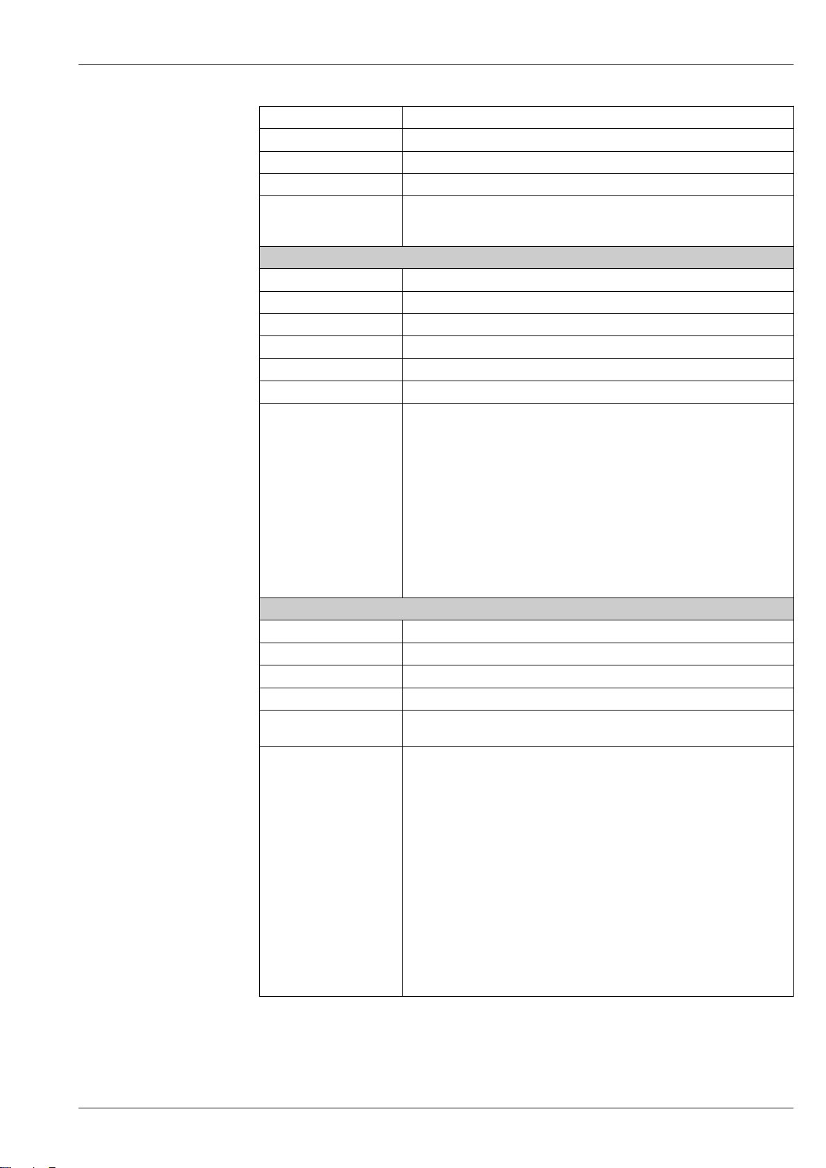
Open-circuit voltage DC 28.8 V (active)
Pulse width Adjustable: 0.05 to 2 000 ms
Maximum pulse rate 10 000 Impulse/s
Pulse value Adjustable
Assignable measured
variables
Frequency output
Maximum input values DC 30 V, 250 mA (passive)
Maximum output current 22.5 mA (active)
Open-circuit voltage DC 28.8 V (active)
Output frequency Adjustable: end value frequency 2 to 10 000 Hz (f
Damping Adjustable: 0 to 999 s
Pulse/pause ratio 1:1
Assignable measured
variables
Switch output
Maximum input values DC 30 V, 250 mA (passive)
Open-circuit voltage DC 28.8 V (active)
Switching behavior Binary, conductive or non-conductive
Switching delay Adjustable: 0 to 100 s
Number of switching
cycles
Assignable functions • Off
• Mass flow
• Volume flow
• Corrected volume flow
• Mass flow
• Volume flow
• Corrected volume flow
• Density
• Reference density
• Temperature
• Electronic temperature
• Oscillation frequency 0
• Oscillation damping 0
• Signal asymmetry
• Exciter current 0
The range of options increases if the measuring device has one or more
application packages.
Unlimited
• On
• Diagnostic behavior
• Limit value
– Mass flow
– Volume flow
– Corrected volume flow
– Density
– Reference density
– Temperature
– Totalizer 1-3
• Flow direction monitoring
• Status
– Partially filled pipe detection
– Low flow
The range of options increases if the measuring device has one or more
application packages.
= 12 500 Hz)
max
Endress+Hauser 15
Page 16
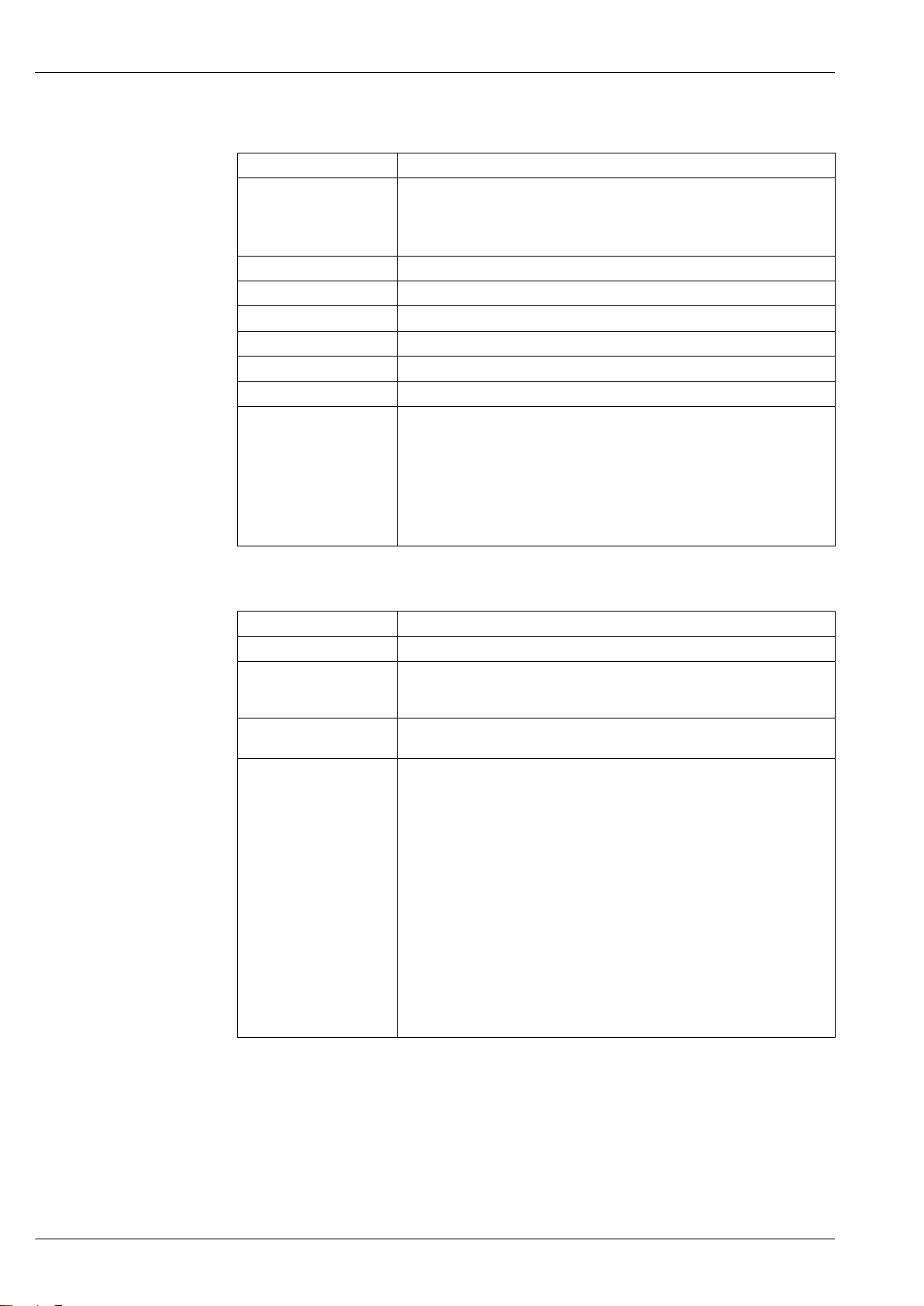
Double pulse output
Function Double pulse
Version Open collector
Can be set to:
• Active
• Passive
Maximum input values DC 30 V, 250 mA (passive)
Open-circuit voltage DC 28.8 V (active)
Voltage drop For 22.5 mA: ≤ DC 2 V
Output frequency Adjustable: 0 to 1 000 Hz
Damping Adjustable: 0 to 999 s
Pulse/pause ratio 1:1
Assignable measured
variables
• Mass flow
• Volume flow
• Corrected volume flow
• Density
• Reference density
• Temperature
The range of options increases if the measuring device has one or more
application packages.
Proline Promass P 300
Relay output
Function Switch output
Version Relay output, galvanically isolated
Switching behavior Can be set to:
• NO (normally open), factory setting
• NC (normally closed)
Maximum switching
capacity (passive)
Assignable functions • Off
• DC 30 V, 0.1 A
• AC 30 V, 0.5 A
• On
• Diagnostic behavior
• Limit value
– Mass flow
– Volume flow
– Corrected volume flow
– Density
– Reference density
– Temperature
– Totalizer 1-3
• Flow direction monitoring
• Status
– Partially filled pipe detection
– Low flow
The range of options increases if the measuring device has one or more
application packages.
User configurable input/output
One specific input or output is assigned to a user-configurable input/output (configurable I/O)
during device commissioning.
The following inputs and outputs are available for assignment:
• Choice of current output: 4 to 20 mA (active), 0/4 to 20 mA (passive)
• Pulse/frequency/switch output
• Choice of current input: 4 to 20 mA (active), 0/4 to 20 mA (passive)
• Status input
16 Endress+Hauser
Page 17
Proline Promass P 300
The technical values correspond to those of the inputs and outputs described in this section.
Signal on alarm
Depending on the interface, failure information is displayed as follows:
HART current output
Device diagnostics Device condition can be read out via HART Command 48
PROFIBUS PA
Status and alarm
messages
Failure current FDE (Fault
Disconnection Electronic)
Diagnostics in accordance with PROFIBUS PA Profile 3.02
0 mA
PROFIBUS DP
Status and alarm
messages
Diagnostics in accordance with PROFIBUS PA Profile 3.02
EtherNet/IP
Device diagnostics Device condition can be read out in Input Assembly
PROFINET
Device diagnostics According to "Application Layer protocol for decentralized periphery", Version 2.3
FOUNDATION Fieldbus
Status and alarm
messages
Failure current FDE (Fault
Disconnection Electronic)
Diagnostics in accordance with FF-891
0 mA
Modbus RS485
Failure mode Choose from:
• NaN value instead of current value
• Last valid value
Current output 0/4 to 20 mA
4 to 20 mA
Failure mode Choose from:
• 4 to 20 mA in accordance with NAMUR recommendation NE 43
• 4 to 20 mA in accordance with US
• Min. value: 3.59 mA
• Max. value: 22.5 mA
• Freely definable value between: 3.59 to 22.5 mA
• Actual value
• Last valid value
Endress+Hauser 17
Page 18
0 to 20 mA
Failure mode Choose from:
• Maximum alarm: 22 mA
• Freely definable value between: 0 to 20.5 mA
Pulse/frequency/switch output
Pulse output
Failure mode Choose from:
• Actual value
• No pulses
Frequency output
Failure mode Choose from:
• Actual value
• 0 Hz
• Defined value (f
Switch output
Failure mode Choose from:
• Current status
• Open
• Closed
2 to 12 500 Hz)
max
Proline Promass P 300
Relay output
Failure mode Choose from:
• Current status
• Open
• Closed
Local display
Plain text display With information on cause and remedial measures
Backlight Red backlighting indicates a device error.
Status signal as per NAMUR recommendation NE 107
Interface/protocol
• Via digital communication:
– HART protocol
– FOUNDATION Fieldbus
– PROFIBUS PA
– PROFIBUS DP
– Modbus RS485
– EtherNet/IP
– PROFINET
• Via service interface
– CDI-RJ45 service interface
– WLAN interface
Plain text display With information on cause and remedial measures
Additional information on remote operation → 91
18 Endress+Hauser
Page 19
Proline Promass P 300
Web server
Plain text display With information on cause and remedial measures
Light emitting diodes (LED)
Status information Status indicated by various light emitting diodes
Ex connection data Safety-related values
The following information is displayed depending on the device version:
• Supply voltage active
• Data transmission active
• Device alarm/error has occurred
• EtherNet/IP network available
• EtherNet/IP connection established
• PROFINET network available
• PROFINET connection established
• PROFINET blinking feature
Order code for
Output type Safety-related values
"Output; input 1"
Option BA Current output
4 to 20 mA HART
UN = 30 V
UM = 250 V
Option GA PROFIBUS PA UN = 30 V
UM = 250 V
Option LA PROFIBUS DP UN = 30 V
UM = 250 V
Option MA Modbus RS485 UN = 30 V
UM = 250 V
Option SA FOUNDATION Fieldbus UN = 30 V
UM = 250 V
Option NA EtherNet/IP UN = 30 V
UM = 250 V
Option RA PROFINET UN = 30 V
UM = 250 V
Order code for
"Output; input 2";
"Output; input 3"
Output type Safety-related values
Output; input 2 Output; input 3
24 (+) 25 (–) 22 (+) 23 (–)
Option B Current output
4 to 20 mA
Option D User configurable input/
output
Option E Pulse/frequency/switch
output
UN = 30 V
UM = 250 V
UN = 30 V
UM = 250 V
UN = 30 V
UM = 250 V
Option F Double pulse output UN = 30 V
UM = 250 V
Option H Relay output UN = 30 V
IN =100 mADC/500 mA
UM = 250 V
Option I Current input 4 to 20 mA UN = 30 V
UM = 250 V
Option J Status input UN = 30 V
UM = 250 V
"Output; input 1"
26 (+) 27 (–)
DC
AC
DC
AC
DC
AC
DC
AC
DC
AC
DC
AC
DC
AC
DC
AC
DC
AC
DC
AC
DC
AC
DC
AC
AC
DC
AC
DC
AC
Endress+Hauser 19
Page 20
Intrinsically safe values
Proline Promass P 300
Order code for
"Output; input 1"
Option CA Current output
Option HA PROFIBUS PA Ex i Ex ia
Option TA FOUNDATION Fieldbus
1) Only available for the Zone 1; Class I, Division 1 version
2) Only available for the Zone 2; Class I, Division 2 version transmitter
Order code for
"Output; input 2";
"Output; input 3"
Option C Current output
Option G Pulse/frequency/switch
Output type Intrinsically safe values
26 (+) 27 (–)
Ui = 30 V
4 to 20 mA HART Ex i
Ex i
Output type Intrinsically safe values or NIFW values
4 to 20 mA Ex i
output Ex i
li = 100 mA
Pi = 1.25 W
Li = 0
Ci = 0
1)
Ui = 30 V
li = 570 mA
Pi = 8.5 W
Li = 10 µH
Ci = 5 nF
1)
Ex ia
Ui = 30 V
li = 570 mA
Pi = 8.5 W
Li = 10 µH
Ci = 5 nF
Output; input 2 Output; input 3
24 (+) 25 (–) 22 (+) 23 (–)
Ui = 30 V
li = 100 mA
Pi = 1.25 W
Li = 0
Ci = 0
Ui = 30 V
li = 100 mA
Pi = 1.25 W
Li = 0
Ci = 0
"Output; input 1"
2)
Ex ic
Ui = 32 V
li = 570 mA
Pi = 8.5 W
Li = 10 µH
Ci = 5 nF
2)
Ex ic
Ui = 32 V
li = 570 mA
Pi = 8.5 W
Li = 10 µH
Ci = 5 nF
Low flow cut off
Galvanic isolation
The switch points for low flow cut off are user-selectable.
The outputs are galvanically isolated from one another and from earth (PE).
Protocol-specific data HART
Manufacturer ID 0x11
Device type ID 0x3B
HART protocol revision 7
Device description files
(DTM, DD)
HART load Min. 250 Ω
System integration Information on system integration: Operating Instructions → 110.
Information and files under:
www.endress.com
• Measured variables via HART protocol
• Burst Mode functionality
20 Endress+Hauser
Page 21
Proline Promass P 300
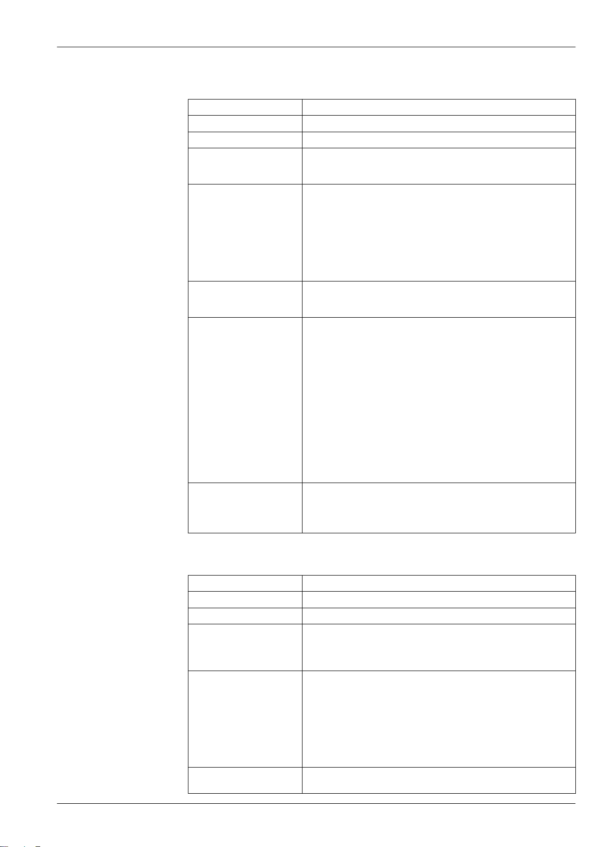
PROFIBUS PA
Manufacturer ID 0x11
Ident number 0x156D
Profile version 3.02
Device description files (GSD,
DTM, DD)
Supported functions • Identification & Maintenance
Configuration of the device
address
Compatibility with
earlier model
System integration Information regarding system integration: Operating Instructions → 110.
Information and files under:
• www.endress.com
• www.profibus.org
Simplest device identification on the part of the control system and
nameplate
• PROFIBUS upload/download
Reading and writing parameters is up to ten times faster with PROFIBUS
upload/download
• Condensed status
Simplest and self-explanatory diagnostic information by categorizing
diagnostic messages that occur
• DIP switches on the I/O electronics module
• Local display
• Via operating tools (e.g. FieldCare)
If the device is replaced, the measuring device Promass 300 supports the
compatibility of the cyclic data with previous models. It is not necessary to
adjust the engineering parameters of the PROFIBUS network with the
Promass 300 GSD file.
Earlier models:
• Promass 80 PROFIBUS PA
– ID No.: 1528 (hex)
– Extended GSD file: EH3x1528.gsd
– Standard GSD file: EH3_1528.gsd
• Promass 83 PROFIBUS PA
– ID No.: 152A (hex)
– Extended GSD file: EH3x152A.gsd
– Standard GSD file: EH3_152A.gsd
Description of the function scope of compatibility:
Operating Instructions → 110.
• Cyclic data transmission
• Block model
• Description of the modules
PROFIBUS DP
Manufacturer ID 0x11
Ident number 0x156F
Profile version 3.02
Device description files (GSD,
DTM, DD)
Supported functions • Identification & Maintenance
Configuration of the device
address
Information and files under:
• www.endress.com
On the product page for the device: Documents/Software → Device drivers
• www.profibus.org
Simplest device identification on the part of the control system and
nameplate
• PROFIBUS upload/download
Reading and writing parameters is up to ten times faster with PROFIBUS
upload/download
• Condensed status
Simplest and self-explanatory diagnostic information by categorizing
diagnostic messages that occur
• DIP switches on the I/O electronics module
• Via operating tools (e.g. FieldCare)
Endress+Hauser 21
Page 22
Proline Promass P 300
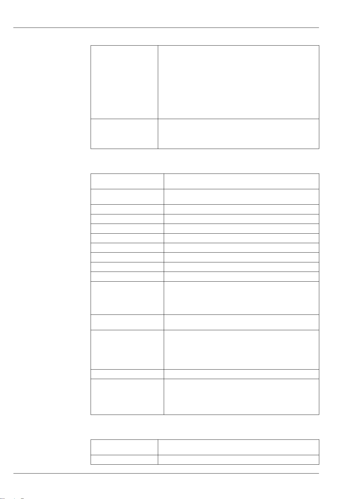
Compatibility with
earlier model
System integration Information regarding system integration: Operating Instructions → 110.
If the device is replaced, the measuring device Promass 300 supports the
compatibility of the cyclic data with previous models. It is not necessary to
adjust the engineering parameters of the PROFIBUS network with the
Promass 300 GSD file.
Previous model:
Promass 83 PROFIBUS DP
– ID No.: 1529 (hex)
– Extended GSD file: EH3x1529.gsd
– Standard GSD file: EH3_1529.gsd
Description of the function scope of compatibility:
Operating Instructions → 110.
• Cyclic data transmission
• Block model
• Description of the modules
EtherNet/IP
Protocol • The CIP Networks Library Volume 1: Common Industrial Protocol
• The CIP Networks Library Volume 2: EtherNet/IP Adaptation of CIP
Communication type • 10Base-T
• 100Base-TX
Device profile Generic device (product type: 0x2B)
Manufacturer ID 0x11
Device type ID 0x103B
Baud rates Automatic ¹⁰⁄₁₀₀ Mbit with half-duplex and full-duplex detection
Polarity Auto-polarity for automatic correction of crossed TxD and RxD pairs
Supported CIP connections Max. 3 connections
Explicit connections Max. 6 connections
I/O connections Max. 6 connections (scanner)
Configuration options for
measuring device
Configuration of the EtherNet
interface
Configuration of the device
address
Device Level Ring (DLR) Yes
System integration Information regarding system integration: Operating Instructions
• DIP switches on the electronics module for IP addressing
• Manufacturer-specific software (FieldCare)
• Add-on Profile Level 3 for Rockwell Automation control systems
• Web browser
• Electronic Data Sheet (EDS) integrated in the measuring device
• Speed: 10 MBit, 100 MBit, auto (factory setting)
• Duplex: half-duplex, full-duplex, auto (factory setting)
• DIP switches on the electronics module for IP addressing (last octet)
• DHCP
• Manufacturer-specific software (FieldCare)
• Add-on Profile Level 3 for Rockwell Automation control systems
• Web browser
• EtherNet/IP tools, e.g. RSLinx (Rockwell Automation)
→ 110.
• Cyclic data transmission
• Block model
• Input and output groups
PROFINET
Protocol "Application layer protocol for decentral device periphery and distributed
Communication type 100 MBit/s
automation", version 2.3
22 Endress+Hauser
Page 23
Proline Promass P 300
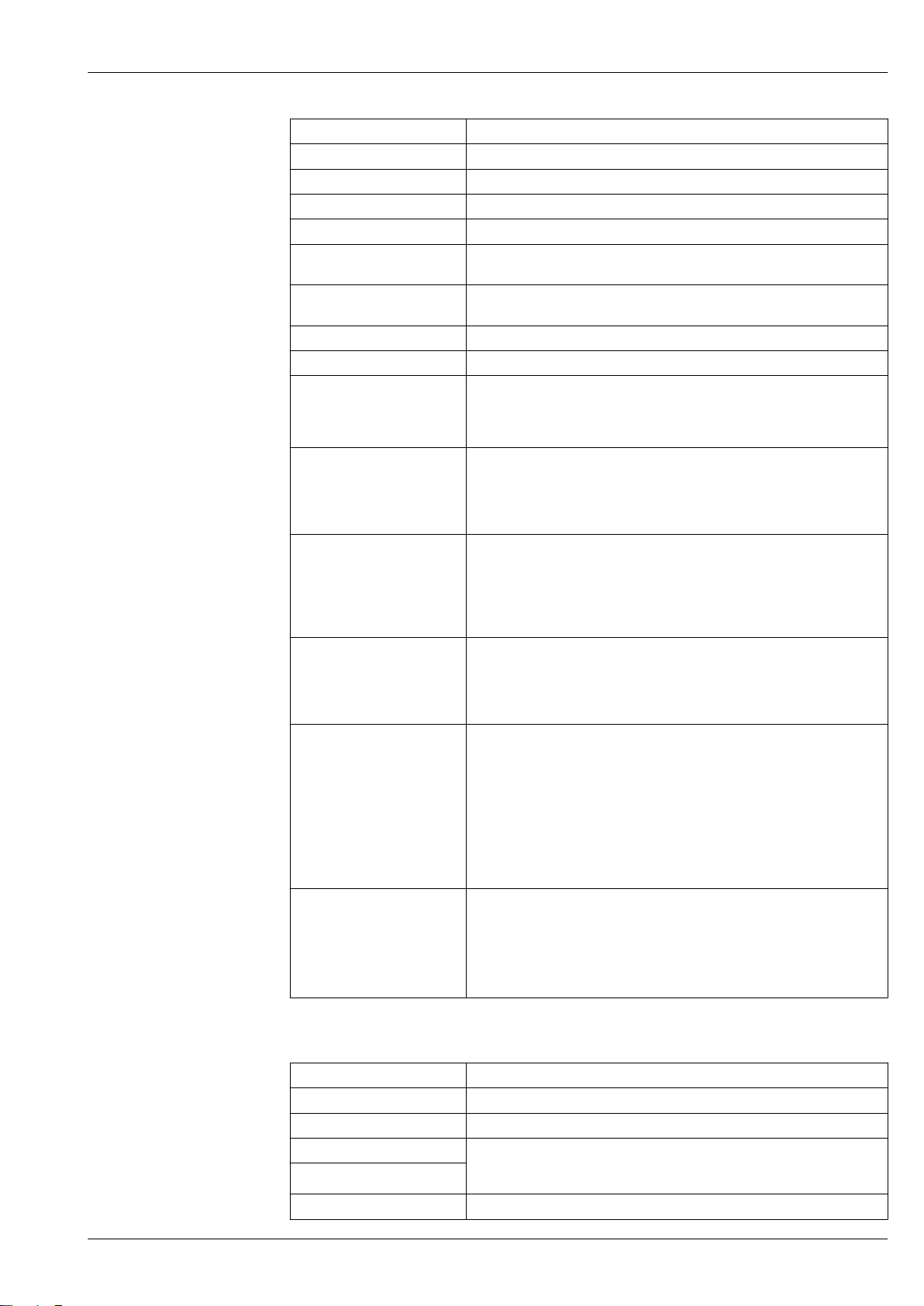
Conformity class Conformance Class B
Netload Class Netload Class II
Baud rates Automatic 100 Mbit/s with full-duplex detection
Cycle times From 8 ms
Polarity Auto-polarity for automatic correction of crossed TxD and RxD pairs
Media Redundancy Protocol
(MRP)
Device profile Application interface identifier 0xF600
Manufacturer ID 0x11
Device type ID 0x843B
Device description files (GSD,
DTM, DD)
Supported connections • 1 x AR (IO Controller AR)
Configuration options for
measuring device
Configuration of the
device name
Supported functions • Identification & Maintenance
System integration Information regarding system integration: Operating Instructions → 110.
Yes
Generic device
Information and files under:
• www.endress.com
On the product page for the device: Documents/Software → Device drivers
• www.profibus.org
• 1 x AR (IO-Supervisor Device AR connection allowed)
• 1 x Input CR (Communication Relation)
• 1 x Output CR (Communication Relation)
• 1 x Alarm CR (Communication Relation)
• DIP switches on the electronics module, for device name assignment (last
part)
• Manufacturer-specific software (FieldCare, DeviceCare)
• Web browser
• Device master file (GSD), can be read out via the integrated Web server of
the measuring device
• DIP switches on the electronics module, for device name assignment (last
part)
• DCP protocol
• Process Device Manager (PDM)
• Integrated Web server
Simple device identification via:
– Control system
– Nameplate
• Measured value status
The process variables are communicated with a measured value status
• Blinking feature via the onsite display for simple device identification and
assignment
• Device operation via operating tools (e.g. FieldCare, DeviceCare, SIMATIC
PDM)
• Cyclic data transmission
• Overview and description of the modules
• Status coding
• Startup configuration
• Factory setting:
FOUNDATION Fieldbus
Manufacturer ID 0x452B48 (hex)
Ident number 0x103B (hex)
Device revision 1
DD revision Information and files under:
CFF revision
Interoperability Test Kit (ITK) Version 6.2.0
• www.endress.com
• www.fieldbus.org
Endress+Hauser 23
Page 24
Proline Promass P 300
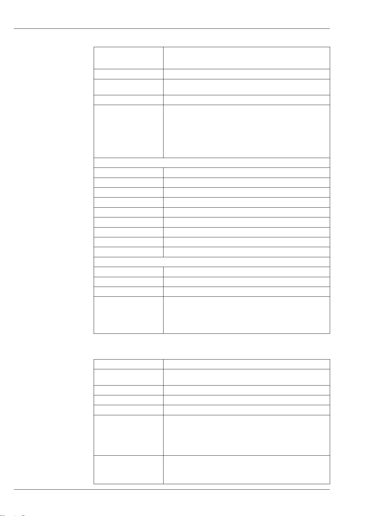
ITK Test Campaign Number Information:
• www.endress.com
• www.fieldbus.org
Link Master capability (LAS) Yes
Choice of "Link Master" and
"Basic Device"
Node address Factory setting: 247 (0xF7)
Supported functions The following methods are supported:
Virtual Communication Relationships (VCRs)
Number of VCRs 44
Number of link objects in VFD 50
Permanent entries 1
Client VCRs 0
Server VCRs 10
Source VCRs 43
Sink VCRs 0
Subscriber VCRs 43
Publisher VCRs 43
Device Link Capabilities
Slot time 4
Min. delay between PDU 8
Max. response delay 16
System integration Information regarding system integration: Operating Instructions → 110.
Yes
Factory setting: Basic Device
• Restart
• ENP Restart
• Diagnostic
• Set to OOS
• Set to AUTO
• Read trend data
• Read event logbook
• Cyclic data transmission
• Description of the modules
• Execution times
• Methods
Modbus RS485
Protocol Modbus Applications Protocol Specification V1.1
Response times • Direct data access: typically 25 to 50 ms
• Auto-scan buffer (data range): typically 3 to 5 ms
Device type Slave
Slave address range 1 to 247
Broadcast address range 0
Function codes • 03: Read holding register
• 04: Read input register
• 06: Write single registers
• 08: Diagnostics
• 16: Write multiple registers
• 23: Read/write multiple registers
Broadcast messages Supported by the following function codes:
• 06: Write single registers
• 16: Write multiple registers
• 23: Read/write multiple registers
24 Endress+Hauser
Page 25

Proline Promass P 300
Supported baud rate • 1 200 BAUD
• 2 400 BAUD
• 4 800 BAUD
• 9 600 BAUD
• 19 200 BAUD
• 38 400 BAUD
• 57 600 BAUD
• 115 200 BAUD
Data transfer mode • ASCII
• RTU
Data access Each device parameter can be accessed via Modbus RS485.
For Modbus register information
Compatibility with
earlier model
System integration Information on system integration: Operating Instructions → 110.
If the device is replaced, the measuring device Promass 300 supports the
compatibility of the Modbus registers for the process variables and the
diagnostic information with the previous model Promass 83. It is not
necessary to change the engineering parameters in the automation system.
Description of the function scope of compatibility:
Operating Instructions → 110.
• Modbus RS485 information
• Function codes
• Register information
• Response time
• Modbus data map
Power supply
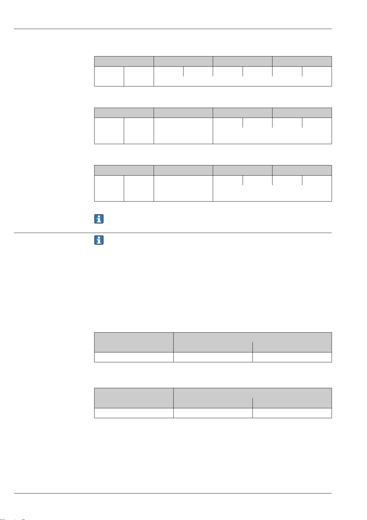
Terminal assignment Transmitter: supply voltage, input/outputs
HART
Supply voltage Input/output 1 Input/output 2 Input/output 3
1 (+) 2 (–) 26 (+) 27 (–) 24 (+) 25 (–) 22 (+) 23 (–)
The terminal assignment depends on the specific device version ordered → 12.
FOUNDATION Fieldbus
Supply voltage Input/output 1 Input/output 2 Input/output 3
1 (+) 2 (–) 26 (A) 27 (B) 24 (+) 25 (–) 22 (+) 23 (–)
The terminal assignment depends on the specific device version ordered → 12.
PROFIBUS PA
Supply voltage Input/output 1 Input/output 2 Input/output 3
1 (+) 2 (–) 26 (B) 27 (A) 24 (+) 25 (–) 22 (+) 23 (–)
The terminal assignment depends on the specific device version ordered → 12.
PROFIBUS DP
Supply voltage Input/output 1 Input/output 2 Input/output 3
1 (+) 2 (–) 26 (B) 27 (A) 24 (+) 25 (–) 22 (+) 23 (–)
The terminal assignment depends on the specific device version ordered → 12.
Endress+Hauser 25
Page 26
Proline Promass P 300
Modbus RS485
Supply voltage Input/output 1 Input/output 2 Input/output 3
1 (+) 2 (–) 26 (B) 27 (A) 24 (+) 25 (–) 22 (+) 23 (–)
The terminal assignment depends on the specific device version ordered → 12.
PROFINET
Supply voltage Input/output 1 Input/output 2 Input/output 3
1 (+) 2 (–) PROFINET
(RJ45 connector)
EtherNet/IP
Supply voltage Input/output 1 Input/output 2 Input/output 3
1 (+) 2 (–) EtherNet/IP
(RJ45 connector)
24 (+) 25 (–) 22 (+) 23 (–)
The terminal assignment depends on the specific
device version ordered → 12.
24 (+) 25 (–) 22 (+) 23 (–)
The terminal assignment depends on the specific
device version ordered → 12.
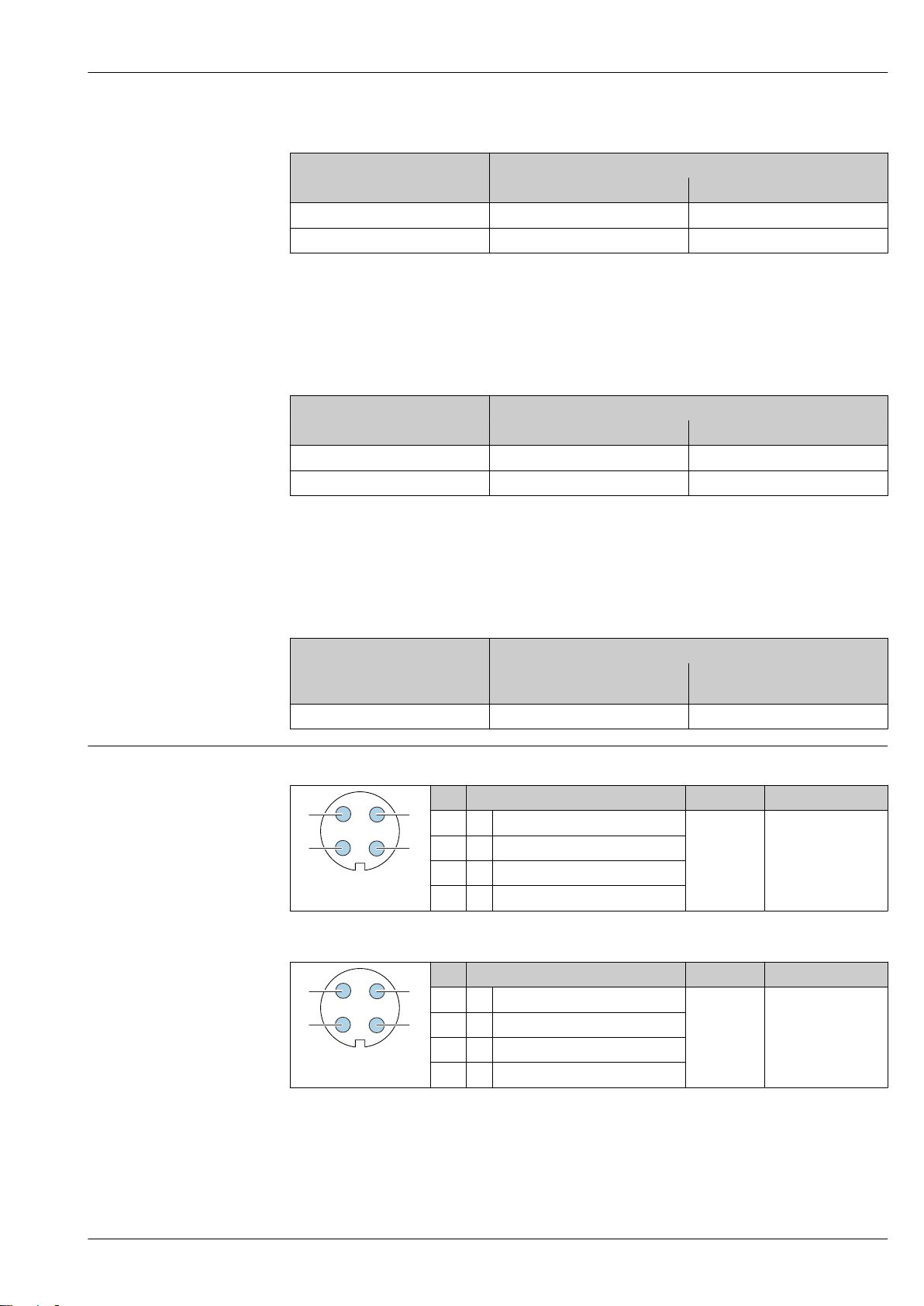
Device plugs available
Terminal assignment of the remote display and operating module → 31.
Device plugs may not be used in hazardous areas!
Device plugs for fieldbus systems:
Order code for "Input; output 1"
• Option SA "FOUNDATION Fieldbus" → 26
• Option GA "PROFIBUS PA" → 26
• Option RA "PROFINET" → 27
• Option NA "EtherNet/IP" → 27
Device plug for connecting to the service interface:
Order code for "Accessory mounted"
option NB, adapter RJ45 M12 (service interface) → 28
Order code for "Input; output 1", option SA "FOUNDATION Fieldbus"
Order code for Cable entry/connection → 30
"Electrical connection" 2 3
M, 3, 4, 5 7/8" connector –
Order code for "Input; output 1", option GA "PROFIBUS PA"
Order code for Cable entry/connection → 30
"Electrical connection" 2 3
L, N, P, U Connector M12 × 1 –
26 Endress+Hauser
Page 27
Proline Promass P 300
1
2
4
3
1
2
4
3
Order code for "Input; output 1", option RA "PROFINET"
Order code for Cable entry/connection → 30
"Electrical connection" 2 3
L, N, P, U Connector M12 × 1 –
1) 2)
1) 2)
1) 2)
R
, S
, T
, V
1) 2)
Connector M12 × 1 Connector M12 × 1
1) Cannot be combined with an external WLAN antenna (order code for "Enclosed accessories", option P8) of
an RJ45 M12 adapter for the service interface (order code for "Accessories mounted", option NB) or of the
remote display and operating module DKX001.
2) Suitable for integrating the device in a ring topology.
Order code for "Input; output 1", option NA "EtherNet/IP"
Order code for Cable entry/connection → 30
"Electrical connection" 2 3
L, N, P, U Connector M12 × 1 –
1) 2)
1) 2)
1) 2)
R
, S
, T
, V
1) 2)
Connector M12 × 1 Connector M12 × 1
1) Cannot be combined with an external WLAN antenna (order code for "Enclosed accessories", option P8) of
an RJ45 M12 adapter for the service interface (order code for "Accessories mounted", option NB) or of the
remote display and operating module DKX001
2) Suitable for integrating the device in a ring topology.
Order code for "Accessory mounted", option NB "Adapter RJ45 M12 (service interface)"
Order code Cable entry/coupling → 30
"Accessory mounted" Cable entry
NB Plug M12 × 1 –
Pin assignment, device plug FOUNDATION Fieldbus
PROFIBUS PA
Cable entry
2
3
Pin Assignment Coding Plug/socket
1 + Signal + A Plug
2 - Signal –
3 Grounding
4 Not assigned
Pin Assignment Coding Plug/socket
1 + PROFIBUS PA + A Plug
2 Grounding
3 - PROFIBUS PA –
4 Not assigned
Endress+Hauser 27
Page 28
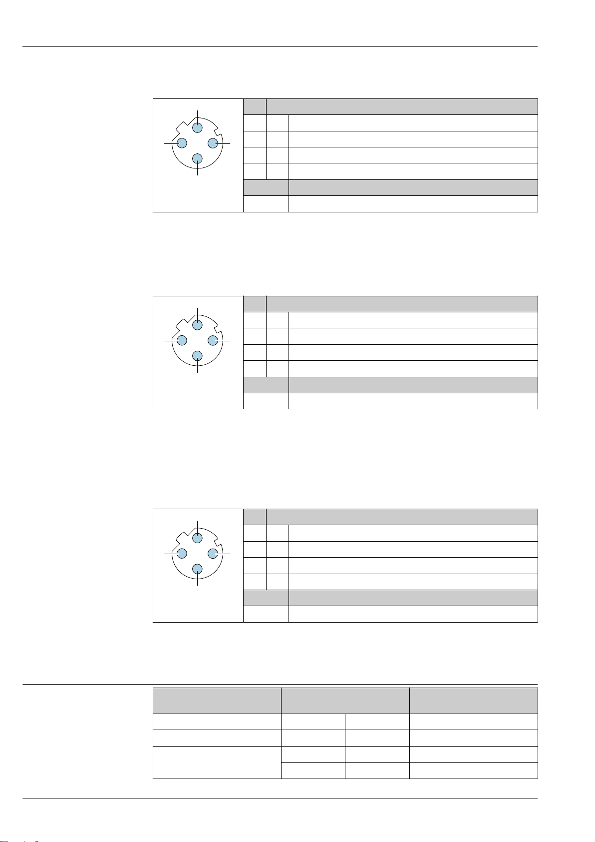
PROFINET
3
2
4
3
2
4
3
2
4
Pin Assignment
1 + TD +
2 + RD +
3 - TD –
4 - RD –
A0032047
Recommended plug:
• Binder, series 763, part no. 99 3729 810 04
• Phoenix, part no. 1543223 SACC-M12MSD-4Q
• When using the device in a hazardous location, use a suitably certified plug.
Coding Plug/socket
D Socket
EtherNet/IP
Pin Assignment
1 + Tx
2 + Rx
3 - Tx
4 - Rx
A0032047
Coding Plug/socket
D Socket
Proline Promass P 300
Supply voltage
Recommended plug:
• Binder, series 763, part no. 99 3729 810 04
• Phoenix, part no. 1543223 SACC-M12MSD-4Q
• When using the device in a hazardous location, use a suitably certified plug.
Service interface
Order code for "Accessories mounted", option NB: Adapter RJ45 M12 (service interface)
Pin Assignment
1 + Tx
2 + Rx
3 - Tx
4 - Rx
A0032047
Recommended plug:
• Binder, series 763, part no. 99 3729 810 04
• Phoenix, part no. 1543223 SACC-M12MSD-4Q
• When using the device in a hazardous location, use a suitably certified plug.
Order code for
"Power supply"
Option D DC24 V ±20% –
Option E AC100 to 240 V –15…+10% 50/60 Hz
Option I
Coding Plug/socket
D Socket
terminal voltage Frequency range
DC24 V ±20% –
AC100 to 240 V –15…+10% 50/60 Hz
28 Endress+Hauser
Page 29

Proline Promass P 300
Power consumption Transmitter
Max. 10 W (active power)
switch-on current Max. 36 A (as per NAMUR Recommendation NE21)
Current consumption Transmitter
• Max. 400 mA (24 V)
• Max. 200 mA (110 V, 50/60 Hz; 230 V, 50/60 Hz)
Power supply failure
• Totalizers stop at the last value measured.
• Depending on the device version, the configuration is retained in the device memoryor in the
pluggable data memory (HistoROM DAT).
• Error messages (incl. total operated hours) are stored.
Endress+Hauser 29
Page 30
Electrical connection Connecting the transmitter
1
2
3
4
1
2
3
4
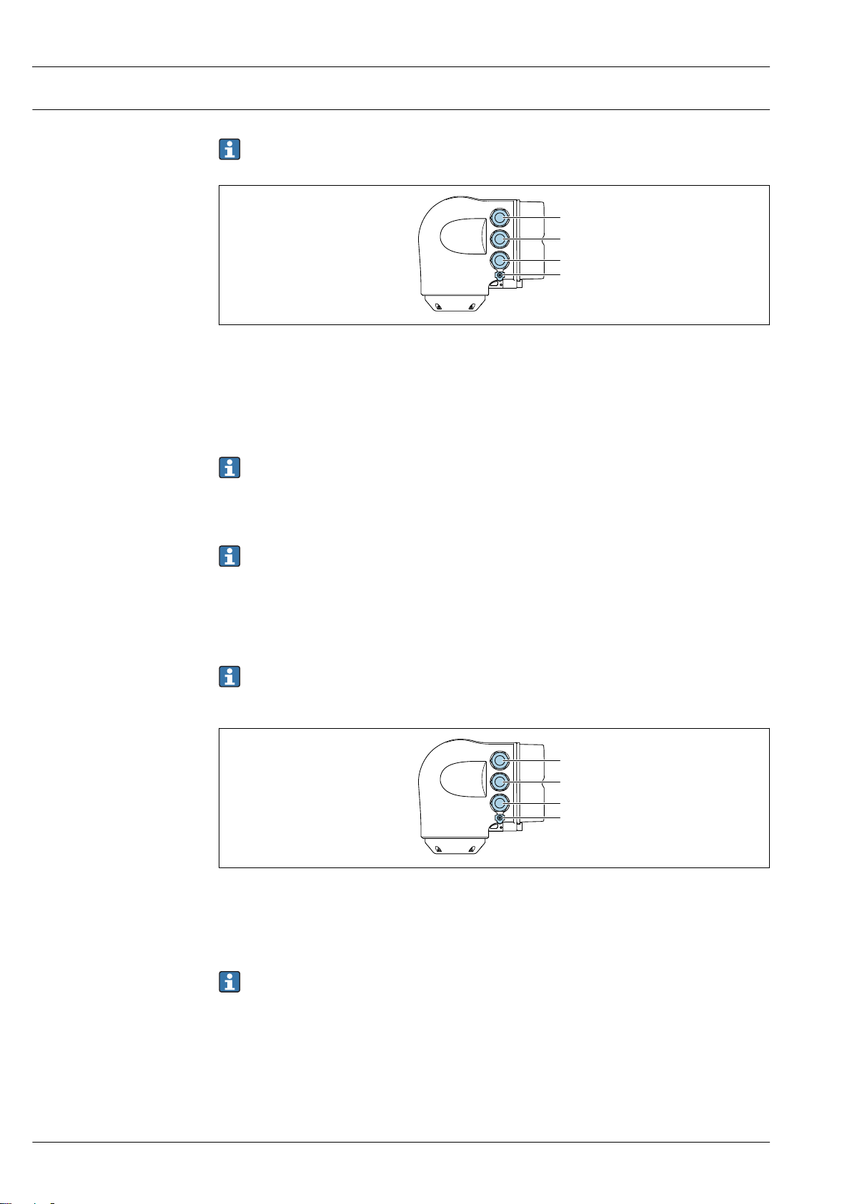
• Terminal assignment→ 25
• Device plugs available→ 26
1 Terminal connection for supply voltage
2 Terminal connection for signal transmission, input/output
3 Terminal connection for signal transmission, input/output or terminal for network connection via service
interface (CDI-RJ45); Optional: terminal connection for external WLAN antenna or connection for remote
display and operating module DKX001
4 Protective ground (PE)
An adapter for RJ45 and the M12 connector is optionally available:
Order code for "Accessories", option NB: "Adapter RJ45 M12 (service interface)"
The adapter connects the service interface (CDI-RJ45) to an M12 connector mounted in the
cable entry. Therefore the connection to the service interface can be established via an M12
connector without opening the device.
Network connection via service interface (CDI-RJ45) → 97
Proline Promass P 300
A0026781
Connecting in a ring topology
Device versions with EtherNet/IP and PROFINET communication protocols can be integrated into a
ring topology. The device is integrated via the terminal connection for signal transmission (output 1)
and the connection to the service interface (CDI-RJ45).
Integrate the transmitter into a ring topology:
• EtherNet/IP → 95
• PROFINET → 96
A0026781
1 Terminal connection for supply voltage
2 Terminal connection for signal transmission: PROFINET or EtherNet/IP (RJ45 connector)
3 Connection to service interface (CDI-RJ45)
4 Protective earth (PE)
If the device has additional input/outputs, these are routed via the cable entry for the
connection to the service interface (CDI-RJ45).
30 Endress+Hauser
Page 31
Proline Promass P 300
1
3
81
Vcc
82
Gnd
83A84
B
81
Vcc
82
Gnd
83A84
B
2
4
5
4
4...20 mA
5
2
1
3
6
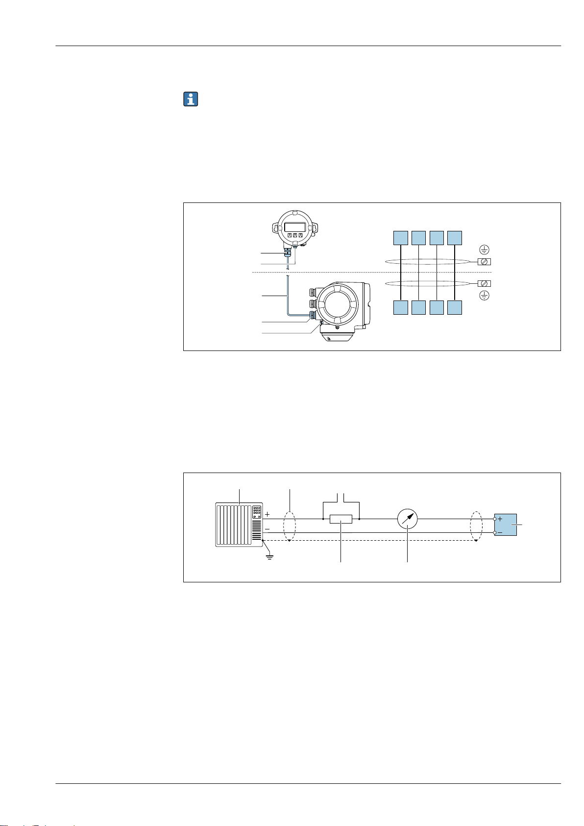
Connecting the remote display and operating module DKX001
The remote display and operating module DKX001 is available as an optional extra → 107.
• The remote display and operating module DKX001 is only available for the following housing
version: order code for "Housing": option A "Aluminum, coated"
• The measuring device is always supplied with a dummy cover when the remote display and
operating module DKX001 is ordered directly with the measuring device. Display or operation
at the transmitter is not possible in this case.
• If ordered subsequently, the remote display and operating module DKX001 may not be
connected at the same time as the existing measuring device display module. Only one
display or operation unit may be connected to the transmitter at any one time.
A0027518
1 Remote display and operating module DKX001
2 Protective earth (PE)
3 Connecting cable
4 Measuring device
5 Protective earth (PE)
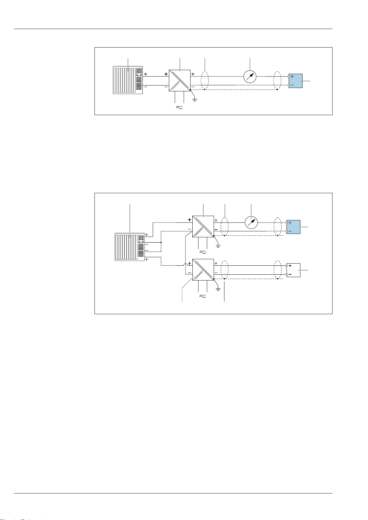
Connection examples
Current output 4 to 20 mA HART
A0029055
2 Connection example for 4 to 20 mA HART current output (active)
1 Automation system with current input (e.g. PLC)
2 Cable shield: the cable shield must be grounded at both ends to comply with EMC requirements; observe cable
specifications → 39
3 Connection for HART operating devices → 91
4 Resistor for HART communication (≥ 250 Ω): observe maximum load → 13
5 Analog display unit: observe maximum load → 13
6 Transmitter
Endress+Hauser 31
Page 32
Proline Promass P 300
2
3
4...20 mA
41
5
2
4...20 mA
4
1
2
3
3
6
5
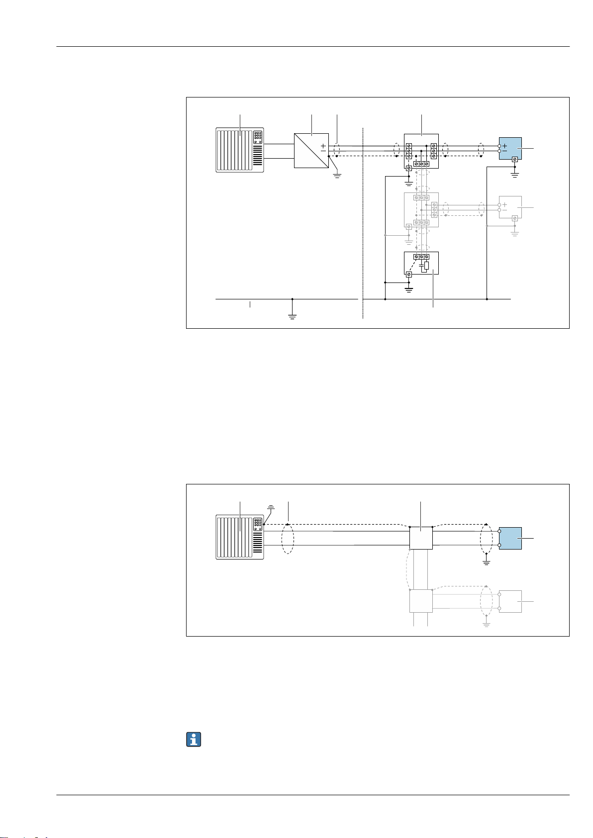
A0028762
3 Connection example for 4 to 20 mA HART current output (passive)
1 Automation system with current input (e.g. PLC)
2 Power supply
3 Cable shield: the cable shield must be grounded at both ends to comply with EMC requirements; observe cable
specifications → 39
4 Analog display unit: observe maximum load → 13
5 Transmitter
HART input
A0028763
4 Connection example for HART input with a common negative (passive)
1 Automation system with HART output (e.g. PLC)
2 Active barrier for power supply (e.g. RN221N)
3 Cable shield: the cable shield must be grounded at both ends to comply with EMC requirements; observe cable
specifications
4 Analog display unit: observe maximum load
5 Pressure transmitter (e.g. Cerabar M, Cerabar S): see requirements
6 Transmitter
32 Endress+Hauser
Page 33
Proline Promass P 300
21 3 4
78
6 6
6
6
5
6
6
5
2
1
A
B
3
4
4
A
B
A
B
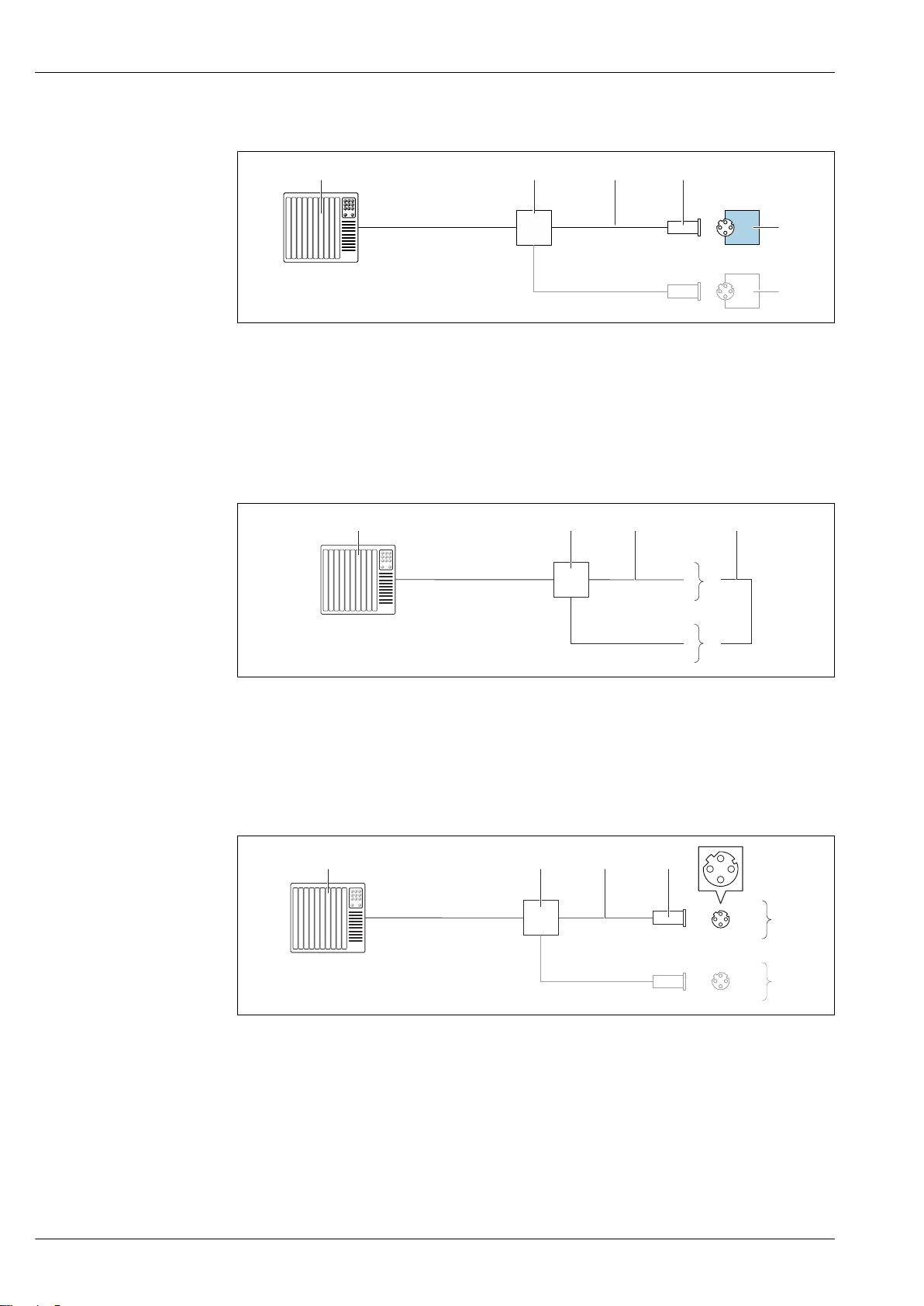
PROFIBUS PA
A0028768
5 Connection example for PROFIBUS PA
1 Control system (e.g. PLC)
2 PROFIBUS PA segment coupler
3 Cable shield: the cable shield must be grounded at both ends to comply with EMC requirements; observe cable
specifications
4 T-box
5 Measuring device
6 Local grounding
7 Bus terminator
8 Potential matching line
PROFIBUS DP
A0028765
6 Connection example for PROFIBUS DP, non-hazardous area and Zone 2/Div. 2
1 Control system (e.g. PLC)
2 Cable shield: the cable shield must be grounded at both ends to comply with EMC requirements; observe cable
specifications
3 Distribution box
4 Transmitter
If baud rates > 1.5 MBaud an EMC cable entry must be used and the cable shield must continue
Endress+Hauser 33
as far as the terminal wherever possible.
Page 34
EtherNet/IP
1
2
4
3
5
5
1 2 4
5
5
3
1 2 4
5
5
3
7 Connection example for EtherNet/IP
1 Control system (e.g. PLC)
2 Ethernet switch
3 Observe cable specifications
4 Device plug
5 Transmitter
EtherNet/IP: DLR (Device Level Ring)
Proline Promass P 300
A0028767
1 Control system (e.g. PLC)
2 Ethernet switch
3 Observe cable specifications → 39
4 Connecting cable between the two transmitters
5 Transmitter
PROFINET
8 Connection example for PROFINET
1 Control system (e.g. PLC)
2 Ethernet switch
3 Observe cable specifications
4 Device plug
5 Transmitter
A0027544
A0016805
34 Endress+Hauser
Page 35
Proline Promass P 300
1 2 4
5
5
3
21 3 4
78
6 6
6
6
5
6
6
5
PROFINET: MRP (Media Redundancy Protocol)
A0027544
1 Control system (e.g. PLC)
2 Ethernet switch
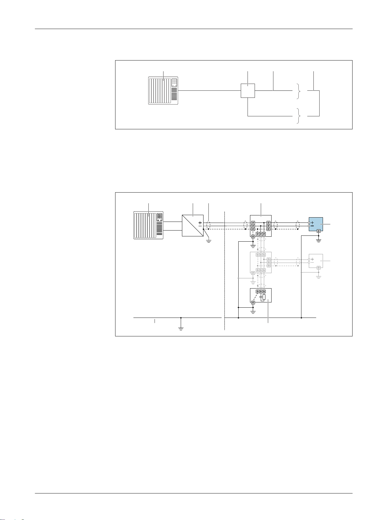
3 Observe cable specifications → 39
4 Connecting cable between the two transmitters
5 Transmitter
FOUNDATION Fieldbus
9 Connection example for FOUNDATION Fieldbus
1 Control system (e.g. PLC)
2 Power Conditioner (FOUNDATION Fieldbus)
3 Cable shield: the cable shield must be grounded at both ends to comply with EMC requirements; observe cable
specifications
4 T-box
5 Measuring device
6 Local grounding
7 Bus terminator
8 Potential matching line
Endress+Hauser 35
A0028768
Page 36
Proline Promass P 300
2
1
A
B
3
4
4
A
B
A
B
4...20 mA
2
1
3
2
4...20 mA
3
1
4
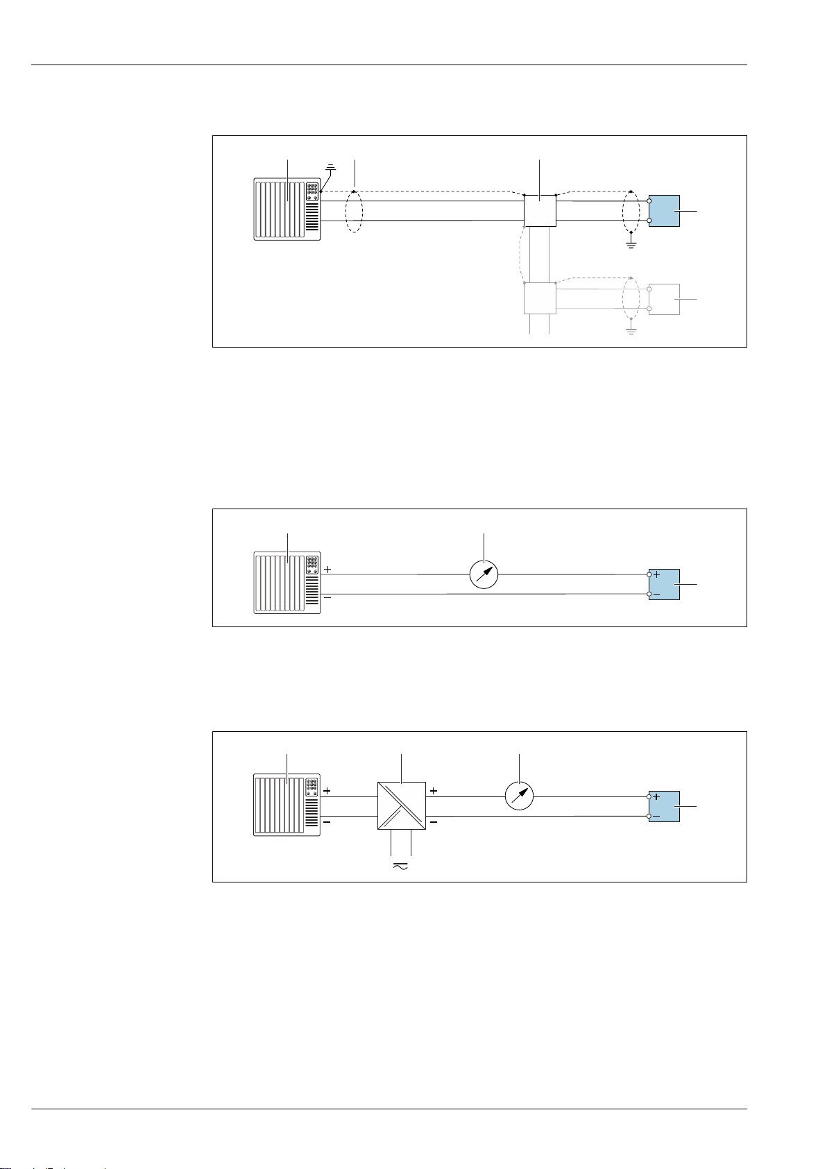
Modbus RS485
A0028765
10 Connection example for Modbus RS485, non-hazardous area and Zone 2; Class I, Division 2
1 Control system (e.g. PLC)
2 Cable shield: the cable shield must be grounded at both ends to comply with EMC requirements; observe cable
specifications
3 Distribution box
4 Transmitter
Current output 4-20 mA
A0028758
11 Connection example for 4-20 mA current output (active)
1 Automation system with current input (e.g. PLC)
2 Analog display unit: observe maximum load
3 Transmitter
A0028759
12 Connection example for 4-20 mA current output (passive)
1 Automation system with current input (e.g. PLC)
2 Active barrier for power supply (e.g. RN221N)
3 Analog display unit: observe maximum load
4 Transmitter
36 Endress+Hauser
Page 37
Proline Promass P 300
1
2
3
12345
1
2
3
1
2
3
4
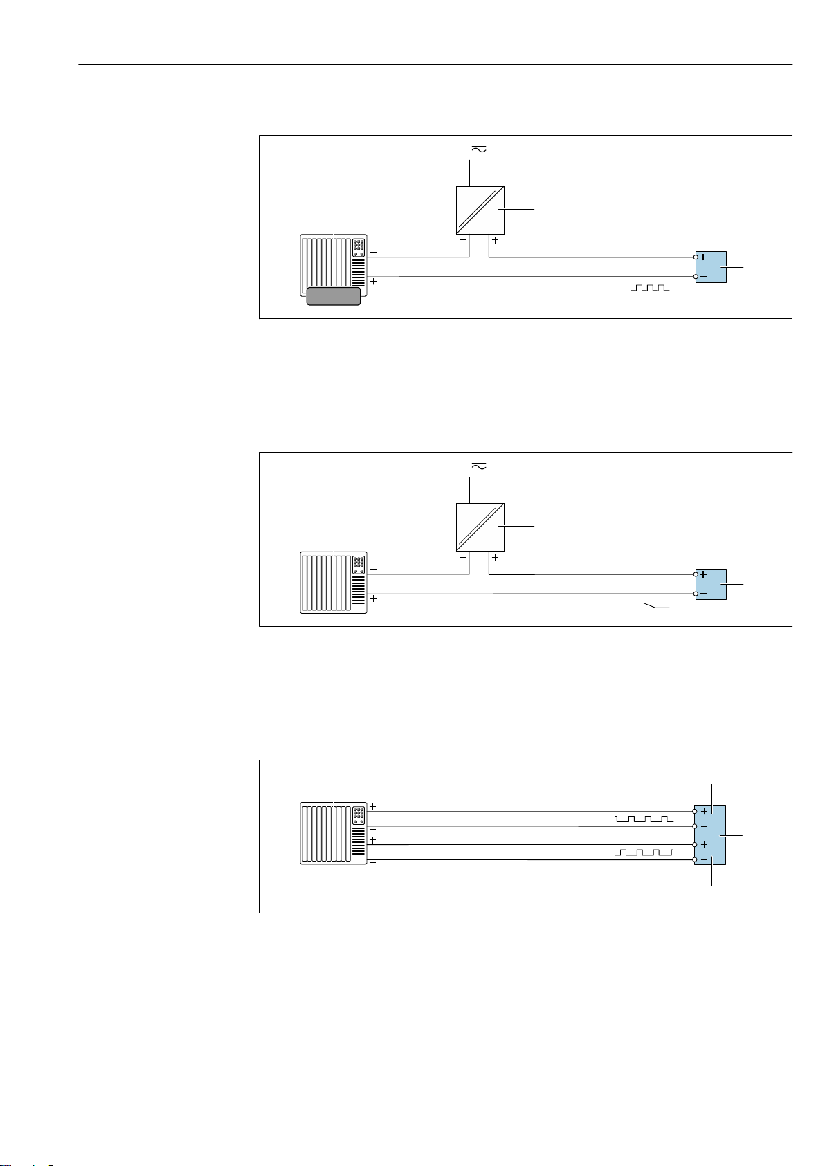
Pulse/frequency output
A0028761
13 Connection example for pulse/frequency output (passive)
1 Automation system with pulse/frequency input (e.g. PLC)
2 Power supply
3 Transmitter: Observe input values → 14
Switch output
14 Connection example for switch output (passive)
1 Automation system with switch input (e.g. PLC)
2 Power supply
3 Transmitter: Observe input values → 14
Double pulse output
15 Connection example for double pulse output (active)
1 Automation system with double pulse input (e.g. PLC)
2 Transmitter: Observe input values → 16
3 Double pulse output
4 Double pulse output (slave), phase-shifted
A0028760
A0029280
Endress+Hauser 37
Page 38
1
3
2
4
5
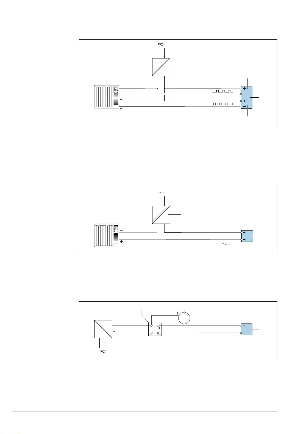
16 Connection example for double pulse output (passive)
1
2
3
31
4
2
1 Automation system with double pulse input (e.g. PLC)
2 Power supply
3 Transmitter: Observe input values → 16
4 Double pulse output
5 Double pulse output (slave), phase-shifted
Proline Promass P 300
A0029279
Relay output
17 Connection example for relay output (passive)
1 Automation system with relay input (e.g. PLC)
2 Power supply
3 Transmitter: Observe input values → 16
Current input
A0028760
A0028915
18 Connection example for 4 to 20 mA current input
1 Power supply
2 Terminal box
3 External measuring device (for reading in pressure or temperature, for instance)
4 Transmitter
38 Endress+Hauser
Page 39
Proline Promass P 300
1
2
3
Status input
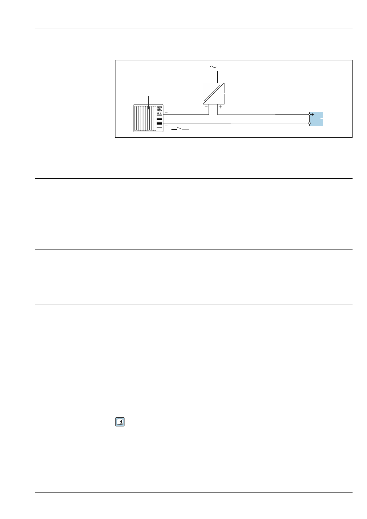
19 Connection example for status input
1 Automation system with status output (e.g. PLC)
2 Power supply
3 Transmitter
Potential equalization Requirements
No special measures for potential equalization are required.
Please consider the following to ensure correct measurement:
• Same electrical potential for the fluid and sensor
• Company-internal grounding concepts
A0028764
terminals
Spring-loaded terminals: Suitable for strands and strands with ferrules.
Conductor cross-section 0.2 to 2.5 mm2 (24 to 12 AWG).
Cable entries
• Cable gland: M20 × 1.5 with cable ⌀ 6 to 12 mm (0.24 to 0.47 in)
• Thread for cable entry:
– NPT ½"
– G ½"
– M20
• Device plug for digital communication: M12
Only available for certain device versions → 26.
Cable specification Permitted temperature range
• The installation guidelines that apply in the country of installation must be observed.
• The cables must be suitable for the minimum and maximum temperatures to be expected.
Power supply cable
Standard installation cable is sufficient.
Signal cable
Current output 4 to 20 mA HART
A shielded cable is recommended. Observe grounding concept of the plant.
PROFIBUS PA
Twisted, shielded two-wire cable. Cable type A is recommended .
For further information on planning and installing PROFIBUS networks see:
• Operating Instructions "PROFIBUS DP/PA: Guidelines for planning and commissioning"
(BA00034S)
• PNO Directive 2.092 "PROFIBUS PA User and Installation Guideline"
• IEC 61158-2 (MBP)
PROFIBUS DP
The IEC 61158 standard specifies two types of cable (A and B) for the bus line which can be used for
every transmission rate. Cable type A is recommended.
Endress+Hauser 39
Page 40
Proline Promass P 300
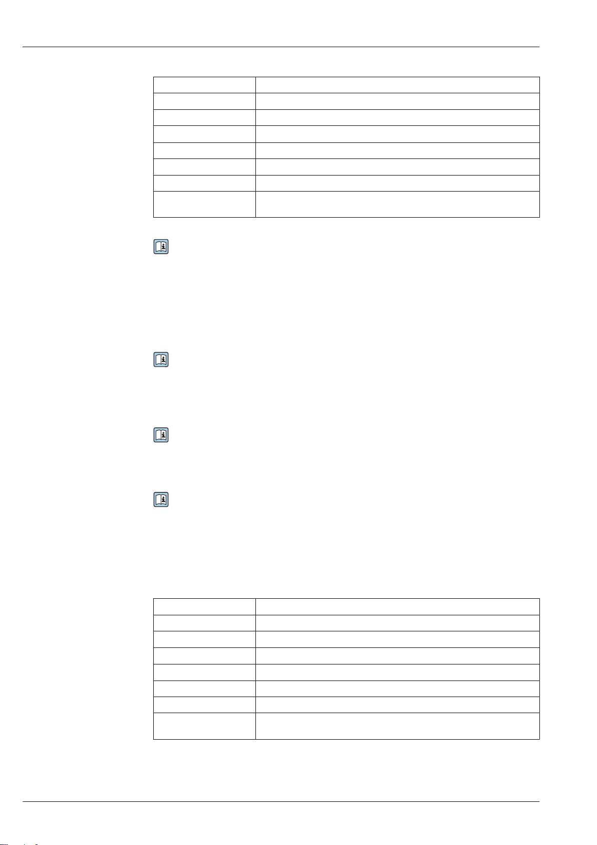
Cable type A
Characteristic impedance 135 to 165 Ω at a measuring frequency of 3 to 20 MHz
Cable capacitance < 30 pF/m
Wire cross-section
Cable type Twisted pairs
Loop resistance ≤110 Ω/km
Signal damping Max. 9 dB over the entire length of the cable cross-section
Shield Copper braided shielding or braided shielding with foil shield. When grounding
For further information on planning and installing PROFIBUS networks see:
• Operating Instructions "PROFIBUS DP/PA: Guidelines for planning and commissioning"
(BA00034S)
• PNO Directive 2.092 "PROFIBUS PA User and Installation Guideline"
• IEC 61158-2 (MBP)
EtherNet/IP
The standard ANSI/TIA/EIA-568-B.2 Annex specifies CAT 5 as the minimum category for a cable
used for EtherNet/IP. CAT 5e and CAT 6 are recommended.
For more information on planning and installing EtherNet/IP networks, please refer to the
"Media Planning and Installation Manual. EtherNet/IP" of ODVA Organization
> 0.34 mm2 (22 AWG)
the cable shield, observe the grounding concept of the plant.
PROFINET
Standard IEC 61156-6 specifies CAT 5 as the minimum category for a cable used for PROFINET. CAT
5e and CAT 6 are recommended.
For more information on planning and installing PROFINET networks, see: "PROFINET Cabling
and Interconnection Technology", Guideline for PROFINET
FOUNDATION Fieldbus
Twisted, shielded two-wire cable.
For further information on planning and installing FOUNDATION Fieldbus networks see:
• Operating Instructions for "FOUNDATION Fieldbus Overview" (BA00013S)
• FOUNDATION Fieldbus Guideline
• IEC 61158-2 (MBP)
Modbus RS485
The EIA/TIA-485 standard specifies two types of cable (A and B) for the bus line which can be used
for every transmission rate. Cable type A is recommended.
Cable type A
Characteristic impedance 135 to 165 Ω at a measuring frequency of 3 to 20 MHz
Cable capacitance < 30 pF/m
Wire cross-section
Cable type Twisted pairs
Loop resistance ≤110 Ω/km
Signal damping Max. 9 dB over the entire length of the cable cross-section
Shield Copper braided shielding or braided shielding with foil shield. When grounding
> 0.34 mm2 (22 AWG)
the cable shield, observe the grounding concept of the plant.
Current output 0/4 to 20 mA
Standard installation cable is sufficient.
40 Endress+Hauser
Page 41
Proline Promass P 300
Pulse/frequency/switch output
Standard installation cable is sufficient.
Double pulse output
Standard installation cable is sufficient.
Relay output
Standard installation cable is sufficient.
Current input 0/4 to 20 mA
Standard installation cable is sufficient.
Status input
Standard installation cable is sufficient.
Connecting cable for transmitter - remote display and operating module DKX001
Standard cable
A standard cable can be used as the connecting cable.
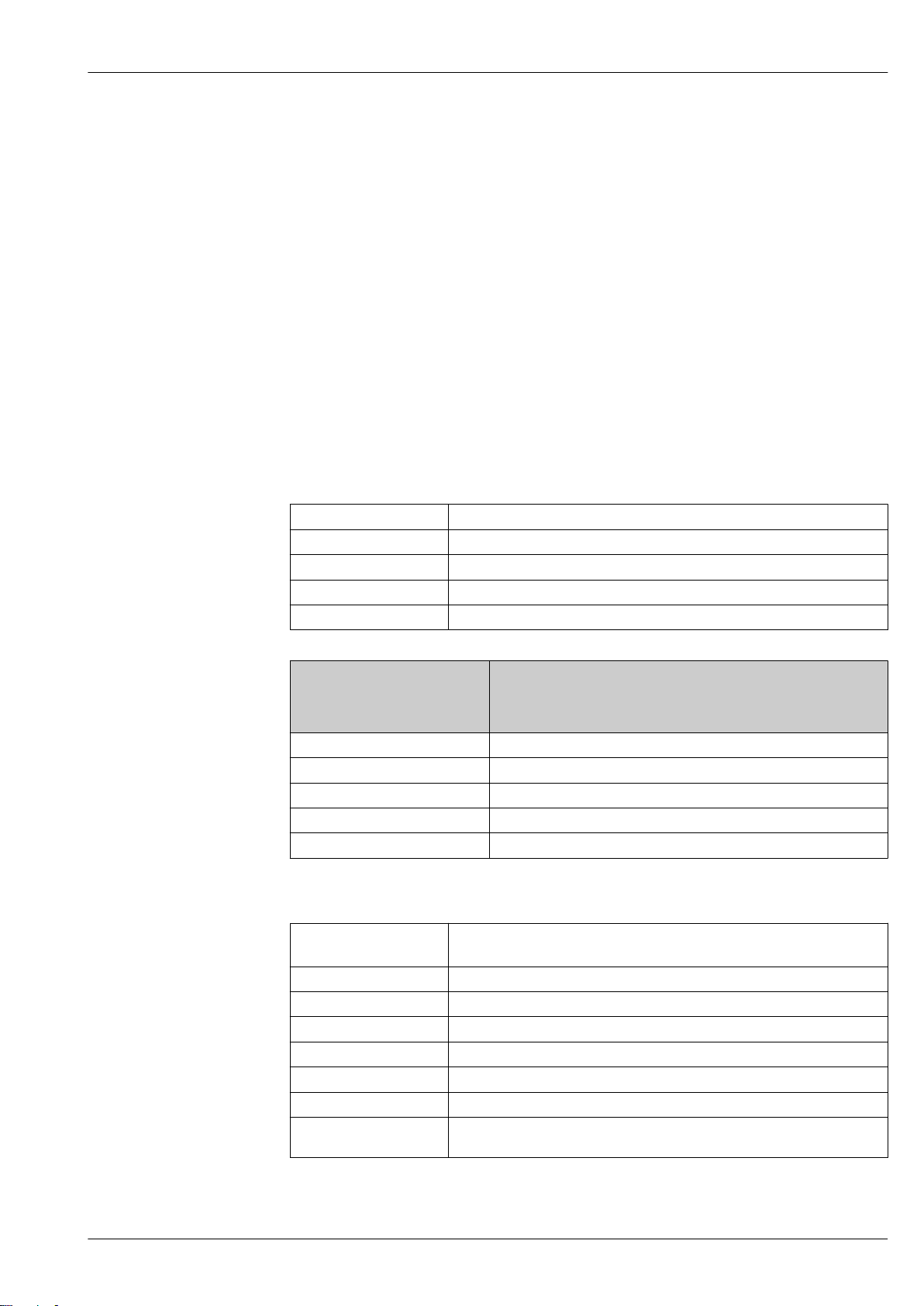
Standard cable 4 cores (2 pairs); pair-stranded with common shield
Shielding Tin-plated copper-braid, optical cover ≥ 85 %
Capacitance: core/shield Maximum 1 000 nF for Zone 1; Class I, Division 1
L/R Maximum 24 µH/Ω for Zone 1; Class I, Division 1
Cable length Maximum 300 m (1 000 ft), see the following table
Cable length for use in:
Cross-section
0.34 mm2 (22 AWG) 80 m (270 ft)
0.50 mm2 (20 AWG) 120 m (400 ft)
0.75 mm2 (18 AWG) 180 m (600 ft)
1.00 mm2 (17 AWG) 240 m (800 ft)
1.50 mm2 (15 AWG) 300 m (1 000 ft)
• Non-hazardous area
• Hazardous area: Zone 2; Class I, Division 2
• Hazardous area: Zone 1; Class I, Division 1
Optionally available connecting cable
Standard cable
Flame resistance According to DIN EN 60332-1-2
Oil-resistance According to DIN EN 60811-2-1
Shielding Tin-plated copper-braid, optical cover ≥ 85 %
Capacitance: core/shield ≤200 pF/m
L/R ≤24 µH/Ω
Available cable length 10 m (35 ft)
Operating temperature When mounted in a fixed position: –50 to +105 °C (–58 to +221 °F); when cable
2 × 2 × 0.34 mm2 (22 AWG) PVC cable
stranded)
can move freely: –25 to +105 °C (–13 to +221 °F)
1)
with common shield (2 pairs, pair-
1) UV radiation can impair the cable outer sheath. Protect the cable from direct sunshine where possible.
Endress+Hauser 41
Page 42
Performance characteristics
Proline Promass P 300
Reference operating conditions
Maximum measured error
• Error limits based on ISO 11631
• Water with +15 to +45 °C (+59 to +113 °F) at2 to 6 bar (29 to 87 psi)
• Specifications as per calibration protocol
• Accuracy based on accredited calibration rigs that are traced to ISO 17025.
To obtain measured errors, use the Applicator sizing tool → 109
o.r. = of reading; 1 g/cm³ = 1 kg/l; T = medium temperature
Base accuracy
Design fundamentals → 45
Mass flow and volume flow (liquids)
±0.10 % o.r.
Density (liquids)
Under
reference operating conditions
[g/cm³] [g/cm³] [g/cm³]
±0.0005 ±0.01 ±0.002
1) Valid over the entire temperature and density range
2) Valid range for special density calibration: 0 to 2 g/cm³, +10 to +80 °C (+50 to +176 °F)
3) Order code for "Application package", option EE "Special density"
Standard density
calibration
1)
Wide-range
Density specification
2) 3)
Temperature
±0.5 °C ± 0.005 · T °C (±0.9 °F ± 0.003 · (T – 32) °F)
Zero point stability
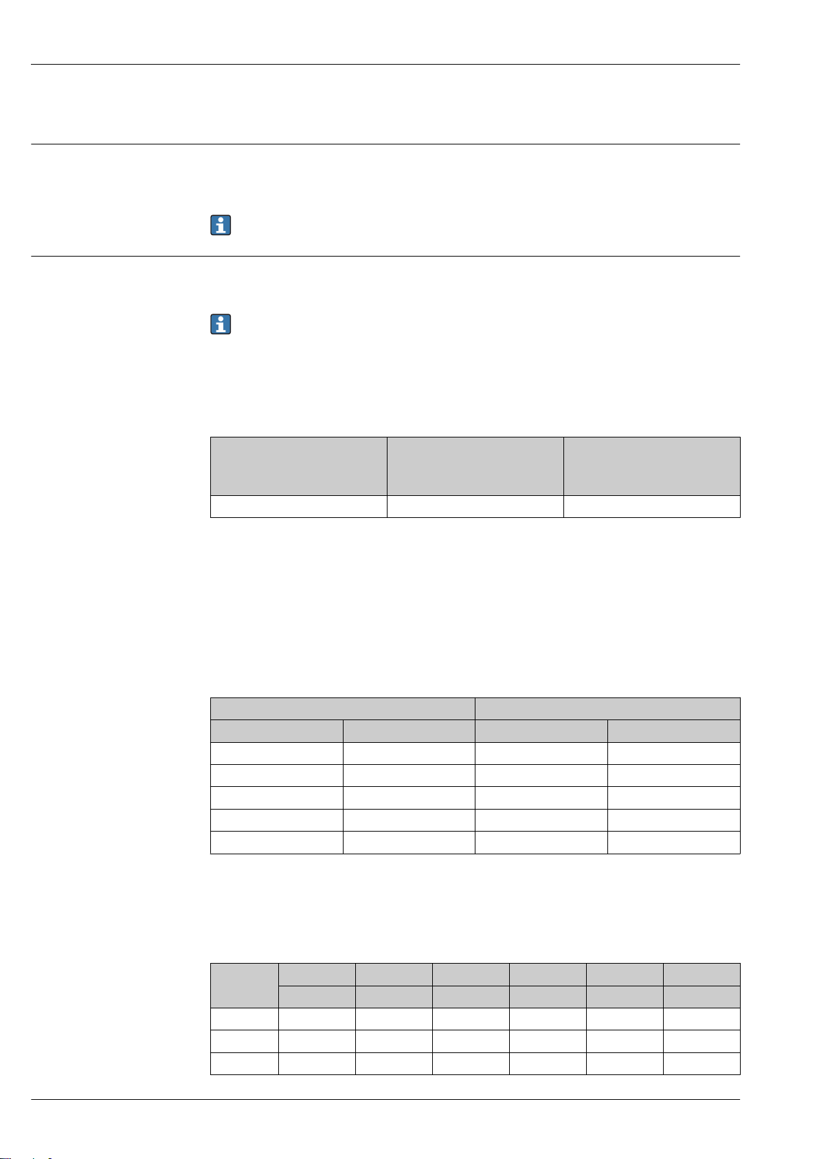
DN Zero point stability
[mm] [in] [kg/h] [lb/min]
8 ³⁄₈ 0.20 0.007
15 ½ 0.65 0.024
25 1 1.80 0.066
40 1½ 4.50 0.165
50 2 7.0 0.257
Flow values
Flow values as turndown parameter depending on nominal diameter.
SI units
DN 1:1 1:10 1:20 1:50 1:100 1:500
[mm]
8 2 000 200 100 40 20 4
15 6 500 650 325 130 65 13
25 18 000 1 800 900 360 180 36
[kg/h] [kg/h] [kg/h] [kg/h] [kg/h] [kg/h]
42 Endress+Hauser
Page 43
Proline Promass P 300
DN 1:1 1:10 1:20 1:50 1:100 1:500
[mm]
40 45 000 4 500 2 250 900 450 90
50 70 000 7 000 3 500 1 400 700 140
[kg/h] [kg/h] [kg/h] [kg/h] [kg/h] [kg/h]
US units
DN 1:1 1:10 1:20 1:50 1:100 1:500
[inch] [lb/min] [lb/min] [lb/min] [lb/min] [lb/min] [lb/min]
³⁄₈ 73.50 7.350 3.675 1.470 0.735 0.147
½ 238.9 23.89 11.95 4.778 2.389 0.478
1 661.5 66.15 33.08 13.23 6.615 1.323
1½ 1 654 165.4 82.70 33.08 16.54 3.308
2 2 573 257.3 128.7 51.46 25.73 5.146
Accuracy of outputs
The outputs have the following base accuracy specifications.
Repeatability
Current output
Accuracy ±5 µA
Pulse/frequency output
o.r. = of reading
Accuracy Max. ±50 ppm o.r. (over the entire ambient temperature range)
o.r. = of reading; 1 g/cm3 = 1 kg/l; T = medium temperature
Base repeatability
Design fundamentals → 45
Mass flow and volume flow (liquids)
±0.05 % o.r.
Density (liquids)
±0.00025 g/cm
3
Temperature
±0.25 °C ± 0.0025 · T °C (±0.45 °F ± 0.0015 · (T–32) °F)
Response time
Influence of ambient
The response time depends on the configuration (damping).
Current output
temperature
Temperature coefficient Max. 1 μA/°C
Pulse/frequency output
Temperature coefficient No additional effect. Included in accuracy.
Endress+Hauser 43
Page 44
Proline Promass P 300
3
[°C]
-40
0
-80
40 80 120 160 200 240 280 320 360 400
[°F]
-50
0
50
100 150
200
0
2
4
6
8
10
14
12
16
1
2
18
20
Influence of medium temperature
Mass flow and volume flow
o.f.s. = of full scale value
When there is a difference between the temperature for zero point adjustment and the process
temperature, the additional measured error of the sensor is typically ±0.0002 % o.f.s./°C (±0.0001 %
o. f.s./°F).
The effect is reduced if zero point adjustment is performed at process temperature.
Density
When there is a difference between the density calibration temperature and the process
temperature, the typical measured error of the sensor is ±0.0001 g/cm3 /°C (±0.00005 g/cm3 /°F).
Field density calibration is possible.
Wide-range density specification (special density calibration)
If the process temperature is outside the valid range (→ 42) the measured error is
±0.0001 g/cm3 /°C (±0.00005 g/cm3 /°F)
Influence of medium pressure
A0016610
1 Field density calibration, for example at +20 °C (+68 °F)
2 Special density calibration
Temperature
±0.005 · T °C (± 0.005 · (T – 32) °F)
The table below shows the effect on accuracy of mass flow due to a difference between calibration
pressure and process pressure.
o.r. = of reading
It is possible to compensate for the effect by:
• Reading in the current pressure measured value via the current input.
• Specifying a fixed value for the pressure in the device parameters.
Operating Instructions→ 110.
DN [% o.r./bar] [% o.r./psi]
[mm] [in]
8 ³⁄₈ –0.002 –0.0001
15 ½ –0.006 –0.0004
25 1 –0.005 –0.0003
44 Endress+Hauser
Page 45
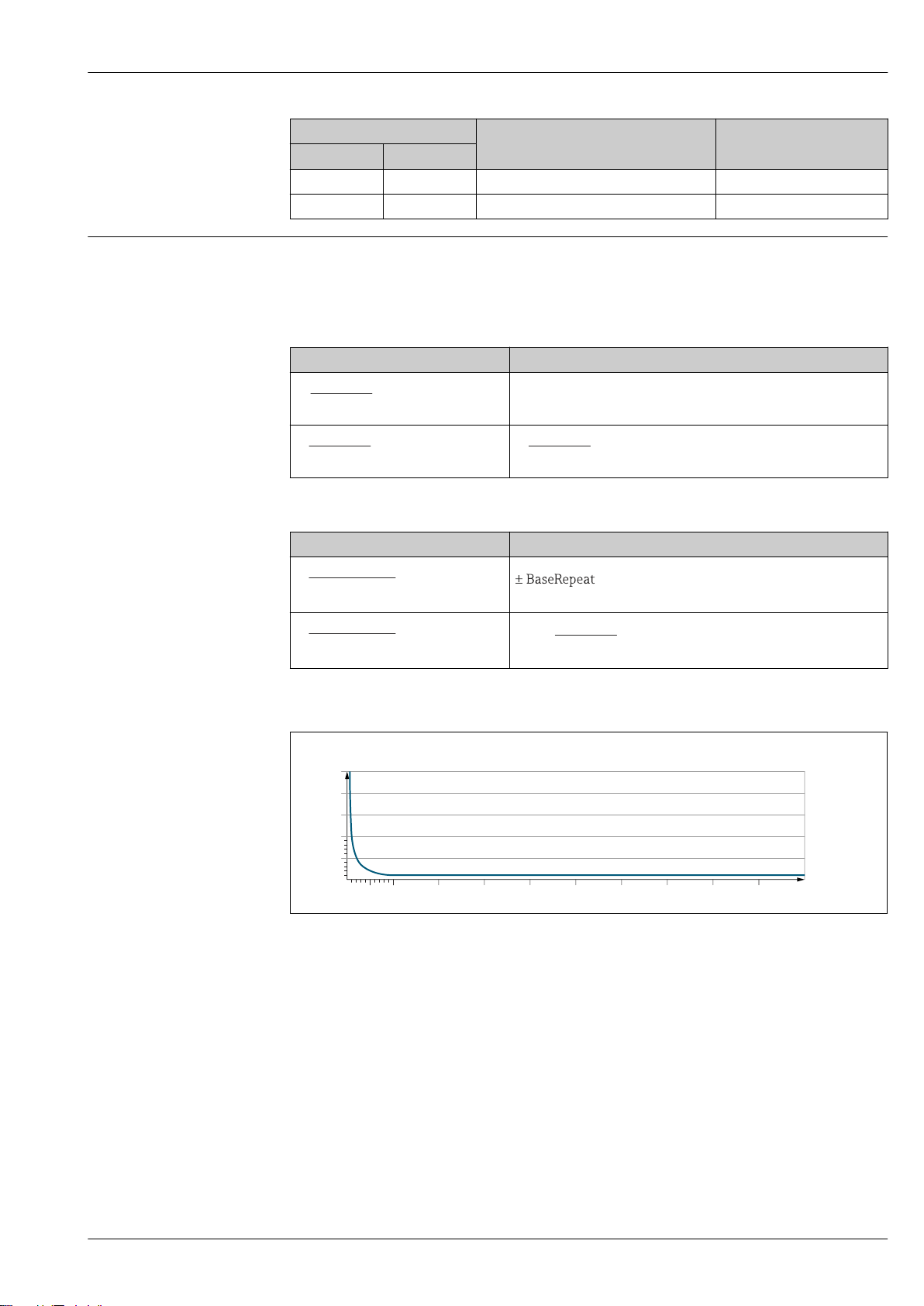
Proline Promass P 300
ZeroPoint
BaseAccu
⋅ 100
³
± BaseAccu
ZeroPoint
BaseAccu
⋅ 100
<
ZeroPoint
MeasValue
⋅ 100
±
½ ⋅ ZeroPoint
BaseRepeat
⋅ 100
³
½ ⋅ ZeroPoint
BaseRepeat
⋅ 100
<
ZeroPoint
MeasValue
⋅ 100
½ ⋅±
E [%]
0 10 20 30 40 50 60
0
0.5
1.0
1.5
2.0
2.5
70 80 90 100
Q [%]
DN [% o.r./bar] [% o.r./psi]
[mm] [in]
40 1½ –0.007 –0.0005
50 2 –0.006 –0.0004
Design fundamentals
o.r. = of reading, o.f.s. = of full scale value
BaseAccu = base accuracy in % o.r., BaseRepeat = base repeatability in % o.r.
MeasValue = measured value; ZeroPoint = zero point stability
Calculation of the maximum measured error as a function of the flow rate
Flow rate Maximum measured error in % o.r.
A0021332
A0021333
Calculation of the maximum repeatability as a function of the flow rate
Flow rate Maximum repeatability in % o.r.
A0021335
A0021336
A0021339
A0021334
A0021340
A0021337
Endress+Hauser 45
Example for maximum measured error
E Maximum measured error in % o.r. (example)
Q Flow rate in % of maximum full scale value
Installation
No special measures such as supports etc. are necessary. External forces are absorbed by the
construction of the device.
A0030317
Page 46
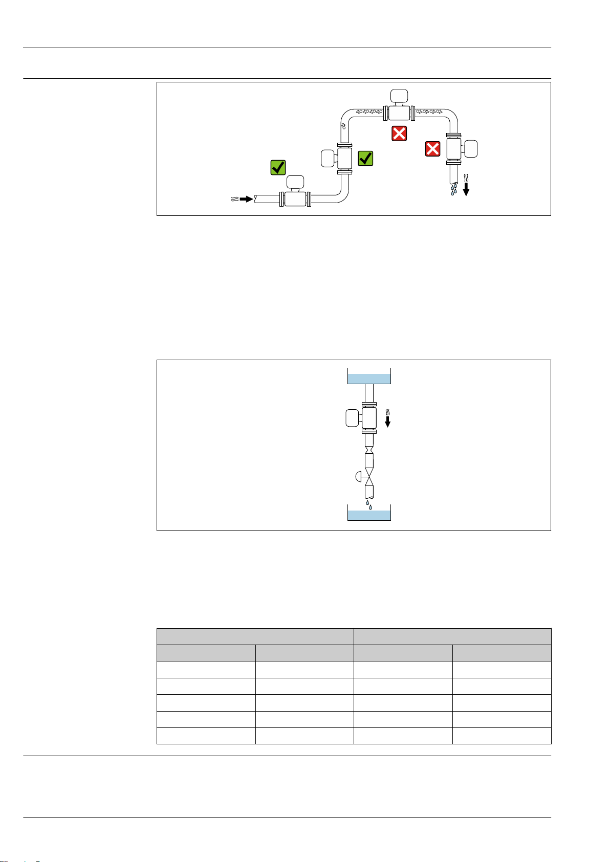
Mounting location
1
2
3
4
5
Proline Promass P 300
A0028772
To prevent measuring errors arising from accumulation of gas bubbles in the measuring tube, avoid
the following mounting locations in the pipe:
• Highest point of a pipeline.
• Directly upstream of a free pipe outlet in a down pipe.
Installation in down pipes
However, the following installation suggestion allows for installation in an open vertical pipeline.
Pipe restrictions or the use of an orifice with a smaller cross-section than the nominal diameter
prevent the sensor running empty while measurement is in progress.
20 Installation in a down pipe (e.g. for batching applications)
1 Supply tank
2 Sensor
3 Orifice plate, pipe restriction
4 Valve
5 Batching tank
DN Ø orifice plate, pipe restriction
[mm] [in] [mm] [in]
8 ³⁄₈ 6 0.24
15 ½ 10 0.40
25 1 14 0.55
Orientation
The direction of the arrow on the sensor nameplate helps you to install the sensor according to the
40 1½ 22 0.87
50 2 28 1.10
flow direction (direction of medium flow through the piping).
46 Endress+Hauser
A0028773
Page 47
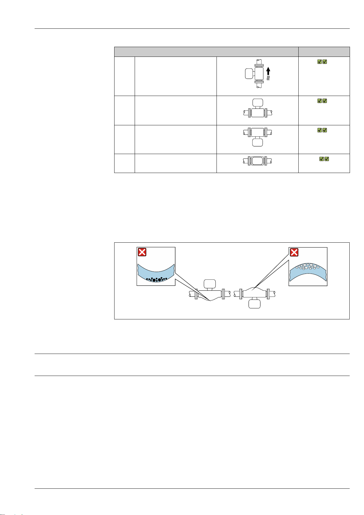
Proline Promass P 300
1 2
Orientation Recommendation
A Vertical orientation
A0015591
B Horizontal orientation, transmitter at
top
1)
2)
Exceptions:
→ 21, 47
A0015589
C Horizontal orientation, transmitter at
bottom
3)
Exceptions:
→ 21, 47
A0015590
D Horizontal orientation, transmitter at
side
A0015592
1) This orientation is recommended to ensure self-draining.
2) Applications with low process temperatures may decrease the ambient temperature. To maintain the
minimum ambient temperature for the transmitter, this orientation is recommended.
3) Applications with high process temperatures may increase the ambient temperature. To maintain the
maximum ambient temperature for the transmitter, this orientation is recommended.
Inlet and outlet runs
Special mounting instructions
If a sensor is installed horizontally with a curved measuring tube, match the position of the sensor to
the fluid properties.
A0028774
21 Orientation of sensor with curved measuring tube
1 Avoid this orientation for fluids with entrained solids: Risk of solids accumulating.
2 Avoid this orientation for outgassing fluids: Risk of gas accumulating.
No special precautions need to be taken for fittings which create turbulence, such as valves, elbows
or T-pieces, as long as no cavitation occurs → 55.
Drainability
When installed vertically, the measuring tube can be drained completely and protected against
buildup.
When the sensor is installed in a horizontal line, eccentric clamps can be used to ensure complete
drainability. When the system is pitched in a specific direction and at a specific slope, gravity can be
used to achieve complete drainability. The sensor must be mounted in the correct position to ensure
full drainability in the horizontal position. Markings on the sensor show the correct mounting
position to optimize drainability.
Endress+Hauser 47
Page 48
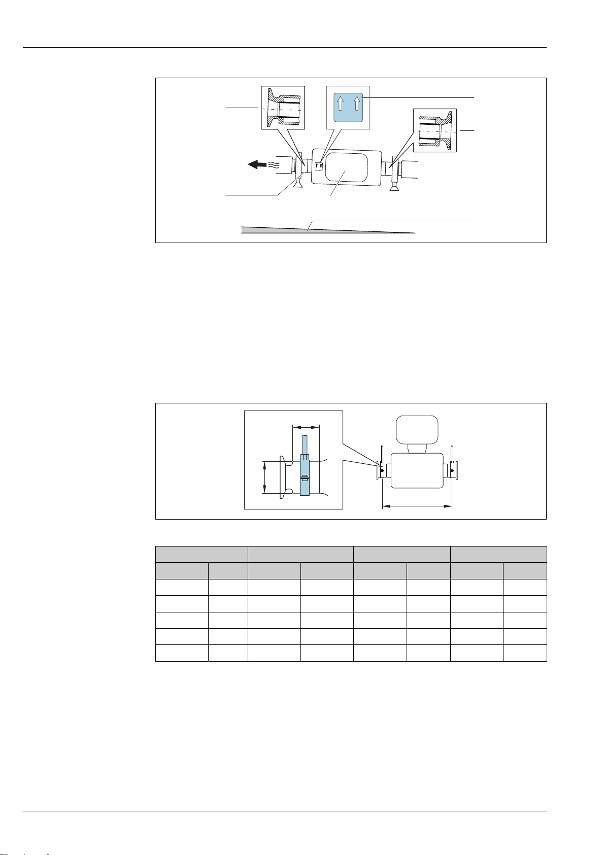
Proline Promass P 300
1
2
4
3
A
B
C
A0016583
1 Eccentric clamp connection
2 "This side up" label indicates which side is up
3 Slope the device in accordance with the hygiene guidelines. Slope: approx. 2 ° or 35 mm/m (0.42 in/feet)
4 Transmitter
5 Line on the underside indicates the lowest point of the eccentric process connection.
Securing with mounting clamp in the case of hygiene connections
It is not necessary to provide additional support for the sensor for operational performance purposes.
If, however, additional support is required for installation purposes, the following dimensions must
be observed.
Use mounting clamp with lining between clamp and measuring instrument.
A0030298
DN A B C
[mm] [in] [mm] [in] [mm] [in] [mm] [in]
8 ³⁄₈ 298 11.73 33 1.3 28 1.1
15 ½ 402 15.83 33 1.3 28 1.1
25 1 542 21.34 33 1.3 38 1.5
40 1 ½ 658 25.91 36.5 1.44 56 2.2
50 2 772 30.39 44.1 1.74 75 2.95
Zero point adjustment
All measuring devices are calibrated in accordance with state-of-the-art technology. Calibration
takes place under reference conditions→ 42. Therefore, a zero point adjustment in the field is
generally not required.
Experience shows that zero point adjustment is advisable only in special cases:
• To achieve maximum measuring accuracy even with low flow rates.
• Under extreme process or operating conditions (e.g. very high process temperatures or very highviscosity fluids).
48 Endress+Hauser
Page 49
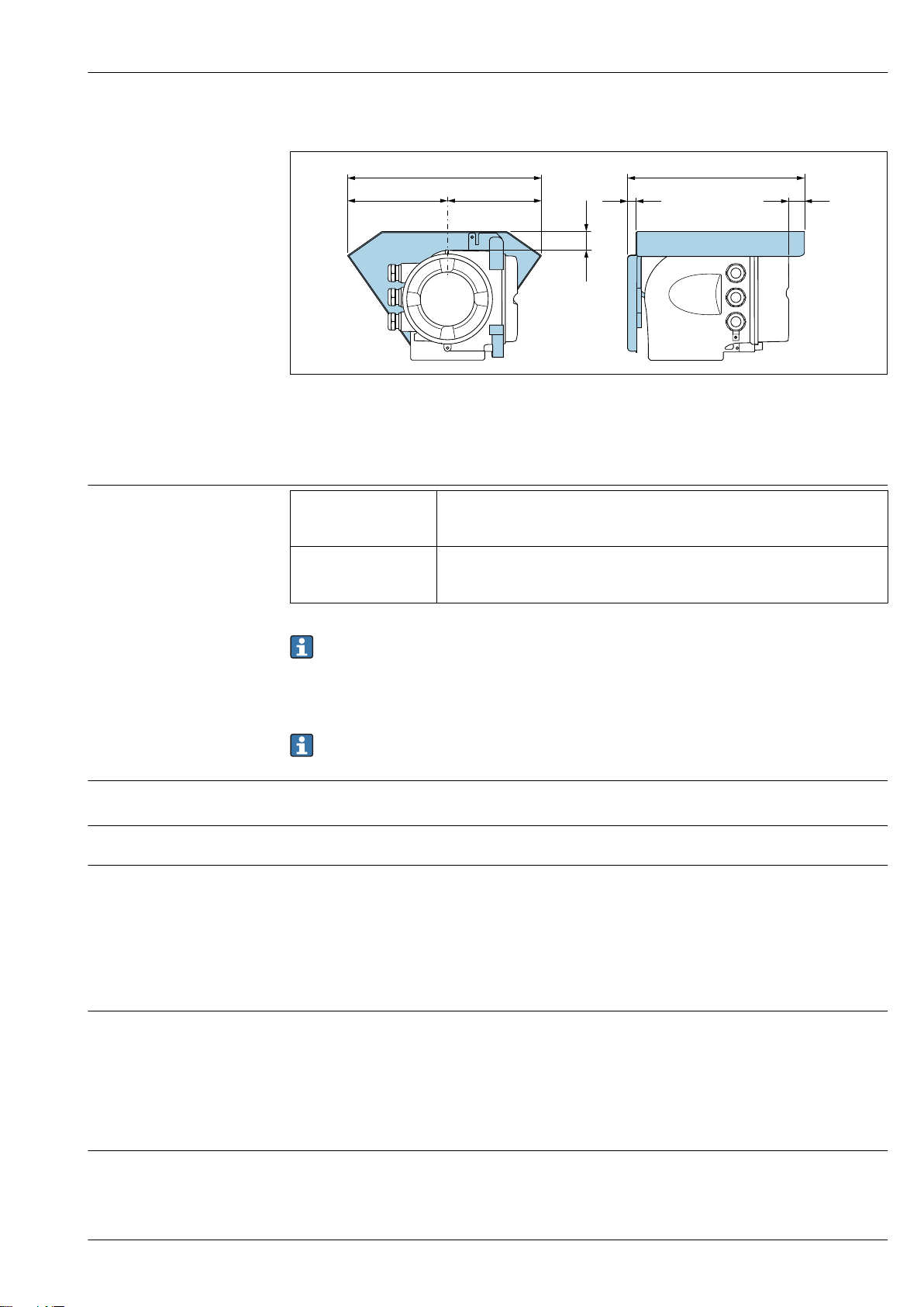
Proline Promass P 300
146 (5.75)
48 (1.9)
12 (0.47)
280 (11.0) 255 (10.0)
134 (5.3)
30 (1.18)
Protective cover
A0029553
Environment
Ambient temperature range
Storage temperature
Climate class
Degree of protection
Measuring device • –40 to +60 °C (–40 to +140 °F)
• Order code for "Test, certificate", option JP:
–50 to +60 °C (–58 to +140 °F)
Readability of the local
display
–20 to +60 °C (–4 to +140 °F)
The readability of the display may be impaired at temperatures outside the
temperature range.
Dependency of ambient temperature on medium temperature→ 50
If operating outdoors:
‣
Avoid direct sunlight, particularly in warm climatic regions.
You can order a weather protection cover from Endress+Hauser. → 107.
–50 to +80 °C (–58 to +176 °F)
DIN EN 60068-2-38 (test Z/AD)
Measuring device
• As standard: IP66/67, type 4X enclosure
• When housing is open: IP20, type 1 enclosure
• Display module: IP20, type 1 enclosure
• With the order code for "Sensor options", option CM: IP69 can also be ordered
External WLAN antenna
IP67
Vibration resistance
• Oscillation, sinusoidal, following IEC 60068-2-6
– 2 to 8.4 Hz, 3.5 mm peak
– 8.4 to 2 000 Hz, 1 g peak
• Oscillation, broadband noise following IEC 60068-2-64
– 10 to 200 Hz, 0.003 g2/Hz
– 200 to 2 000 Hz, 0.001 g2/Hz
– Total: 1.54 g rms
Shock resistance
Shock, half-sine according to IEC 60068-2-27
6 ms 50 g
Endress+Hauser 49
Page 50
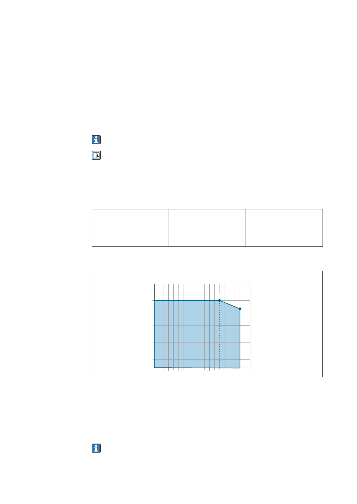
Proline Promass P 300
T
a
T
m
B
A
Shock resistance
Interior cleaning
Electromagnetic compatibility (EMC)
Medium temperature range
Shock due to rough handling following IEC 60068-2-31
• Cleaning in place (CIP)
• Sterilization in place (SIP)
• Cleaning with pigs
Options
Oil- and grease-free version for wetted parts, without declaration
Order code for "Service", option HA
• As per IEC/EN 61326 and NAMUR Recommendation 21 (NE 21)
• Device version with PROFIBUS DP: Complies with emission limits for industry as per EN 50170
Volume 2, IEC 61784
The following applies for PROFIBUS DP: If baud rates > 1.5 MBaud, an EMC cable entry must be
used and the cable shield must continue as far as the terminal wherever possible.
Details are provided in the Declaration of Conformity.
Process
Standard version –50 to +150 °C (–58 to +302 °F) Order code for "Measuring tube
mat., wetted surface", option BB,
BC, BD
Extended temperature version –50 to +205 °C (–58 to +401 °F) Order code for "Measuring tube
mat., wetted surface", option TD, TG
Dependency of ambient temperature on medium temperature
A0031121
22 Exemplary representation, values in the table below.
TaAmbient temperature
TmMedium temperature
A Maximum permitted medium temperature Tm at T
require a reduced ambient temperature T
B Maximum permitted ambient temperature Ta for the maximum specified medium temperature Tm of the
sensor
a
= 60 °C (140 °F); higher medium temperatures T
a max
m
Values for devices used in the hazardous area:
Separate Ex documentation (XA) for the device → 110.
50 Endress+Hauser
Page 51
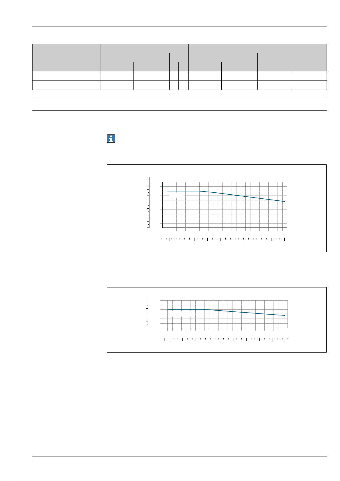
Proline Promass P 300
PN40
300 [° ]F350250200150100500- 05
[°C]200150100500- 05
400
0
10
20
30
40
50
200
400
600
0
800
[bar][psi]
Class 150
300 [°F]350250200150100500-50
[°C]200150100500-50
400
0
10
20
30
[bar][psi]
200
400
0
Not insulated Insulated
A B A B
Version T
Standard version 60 °C (140 °F) 150 °C (302 °F) – – 60 °C (140 °F) 110 °C (230 °F) 55 °C (131 °F) 150 °C (302 °F)
Extended temperature version 60 °C (140 °F) 205 °C (401 °F) – – 60 °C (140 °F) 110 °C (230 °F) 50 °C (122 °F) 205 °C (401 °F)
a
T
m
TaT
m
T
a
T
m
T
a
T
m
Density
Pressure-temperature ratings
0 to 5 000 kg/m3 (0 to 312 lb/cf)
The following pressure/temperature diagrams apply to all pressure-bearing parts of the device and
not just the process connection. The diagrams show the maximum permissible medium pressure
depending on the specific medium temperature.
Pressure-temperature curves with temperature range +151 to +205 °C (+304 to +401 °F)
exclusively for extended temperature version of measuring devices.
Flange according to EN 1092-1 (DIN 2501)
A0027769-EN
23 With flange material 1.4404 (F316/F316L).
Flange according to ASME B16.5
A0026540-EN
24 With flange material 1.4404 (F316/F316L)
Endress+Hauser 51
Page 52
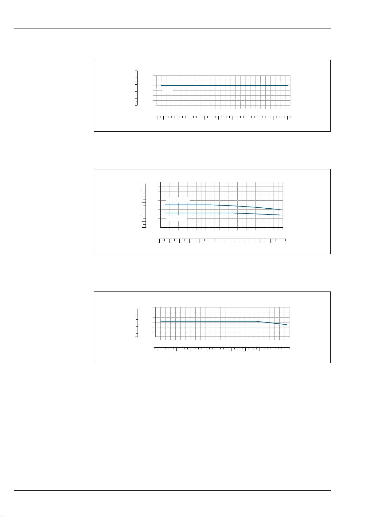
Flange JIS B2220
20K
300 [°F]350250200150100500-50
[°C]200150100500-50
400
0
10
20
30
[bar][psi]
200
400
0
DN8…40
≥ DN50
-80
0 80 160
240
320 400
0
10
20
30
40
0
[°C]
[°F]
[bar][psi]
20015010050
0
-50
50
300 [°F]350250200150100500-50
[°C]200150100500-50
400
0
10
20
30
[bar][psi]
200
400
0
25 With flange material 1.4404 (F316/F316L)
Flange DIN 11864-2 Form A
Proline Promass P 300
A0026541-EN
26 With flange material 1.4435 (316L)
Neumo BioConnect, BBS flange
27 With flange material 1.4435 (316L)
A0027781-EN
A0027782-EN
52 Endress+Hauser
Page 53
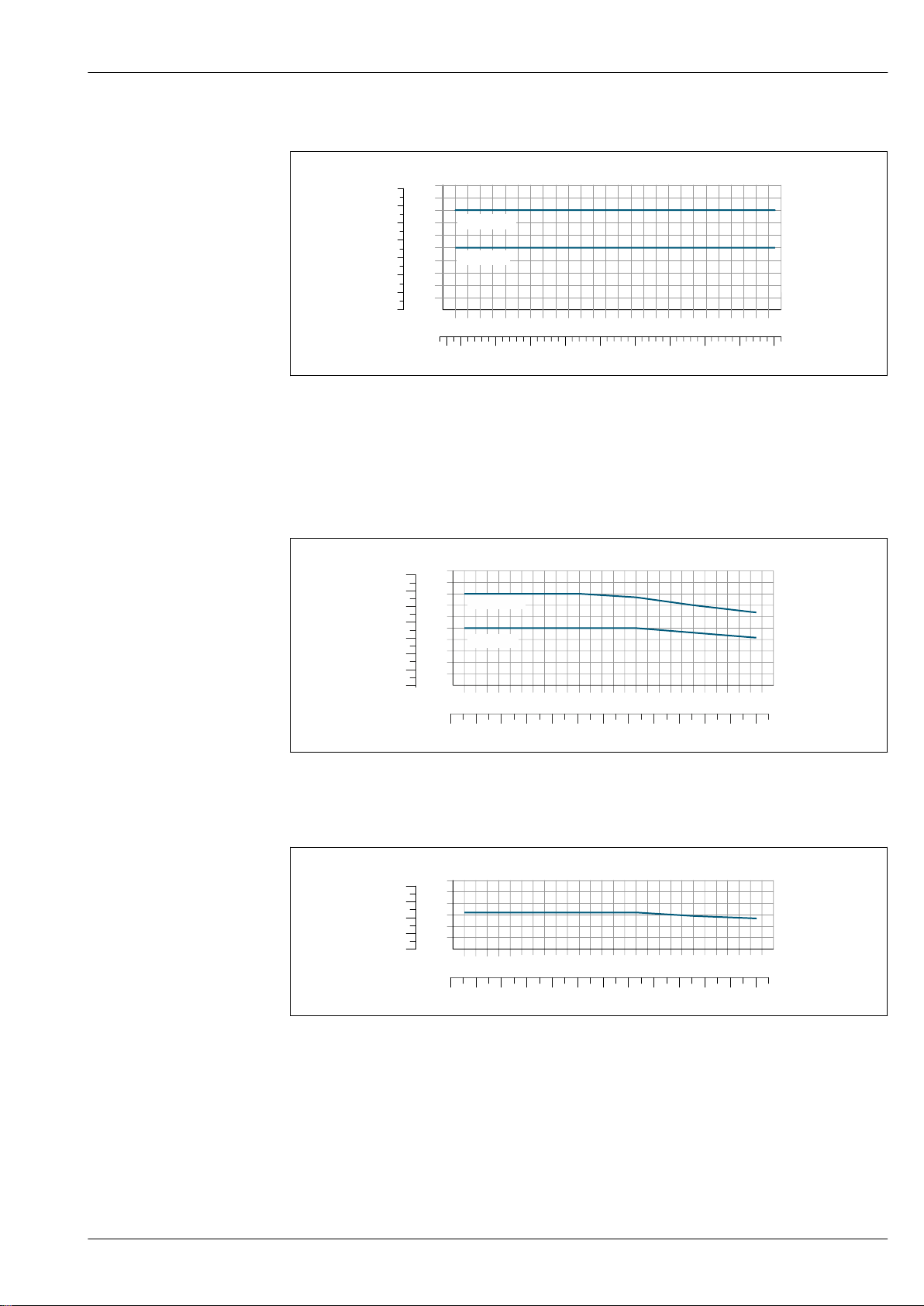
Proline Promass P 300
DN8…40
300 [°F]350250200150100500-50
[°C]200150100500-50
400
0
10
20
30
40
50
[bar][psi]
200
400
600
0
≥DN50
DN8…40
≥ DN50
-80
0 80 160
240
320 400
0
10
20
30
40
0
[°C]
[°F]
[bar][psi]
20015010050
0
-50
50
-80
0 80 160
240
320 400
0
10
20
0
[°C]
[°F]
[bar][psi]
20015010050
0
-50
Thread DIN 11851
A0027783-EN
28 With flange material 1.4435 (316L)
DIN 11851 allows for applications up to +140 °C (+284 °F) if suitable sealing materials are used.
Please take this into account when selecting seals and counterparts, as these components can limit
the pressure and temperature range.
Thread DIN 11864-1 Form A
29 With connection material 1.4435 (316L)
Thread ISO 2853
A0027784-EN
A0027785-EN
30 With connection material 1.4435 (316L)
Endress+Hauser 53
Page 54
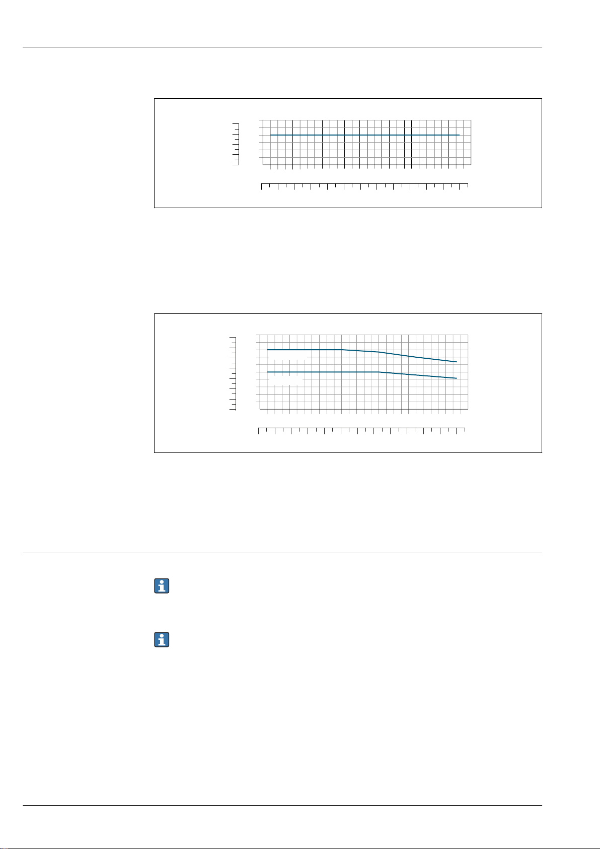
Proline Promass P 300
-80
0 80 160
240
320 400
0
2
6
0
[°C]
[°F]
[bar][psi]
20015010050
0
-50
8
DN8…40
≥ DN50
-80
0 80 160
240
320 400
0
10
20
30
40
0
[°C]
[°F]
[bar][psi]
20015010050
0
-50
50
Thread SMS 1145
A0027786-EN
31 With connection material 1.4435 (316L)
SMS 1145 allows for applications up to 6 bar (87 psi) if suitable sealing materials are used. Please
take this into account when selecting seals and counterparts, as these components can limit the
pressure and temperature range.
Clamp connections DIN 11864-3 Form A
32 With connection material 1.4435 (316L)
Tri-Clamp; clamp connection ISO 2852, DIN 32676, BBS, Neumo BioConnect
The clamp connections are suitable up to a maximum pressure of 16 bar (232 psi). Please observe
the operating limits of the clamp and seal used as they can be over 16 bar (232 psi). The clamp and
seal are not included in the scope of supply.
Sensor housing
The sensor housing is filled with dry nitrogen gas and protects the electronics and mechanics inside.
If a measuring tube fails (e.g. due to process characteristics like corrosive or abrasive fluids), the
fluid will initially be contained by the sensor housing.
If the sensor is to be purged with gas (gas detection), it should be equipped with purge connections.
Do not open the purge connections unless the containment can be filled immediately with a
dry, inert gas. Use only low pressure to purge. Maximum pressure: 5 bar (72.5 psi).
Sensor housing nominal pressure rating and burst pressure
The following sensor housing nominal pressure ratings/burst pressures are only valid for standard
devices and/or devices equipped with closed purge connections (not opened/as delivered).
If a device fitted with purge connections (order code for "Sensor option", option CH "Purge
54 Endress+Hauser
connection") is connected to the purge system, the maximum nominal pressure is determined by the
purge system itself or by the device, depending on which component has the lower nominal pressure
classification.
The sensor housing burst pressure refers to a typical internal pressure which is reached prior to
mechanical failure of the sensor housing and which was determined during type testing. The
A0027784-EN
Page 55
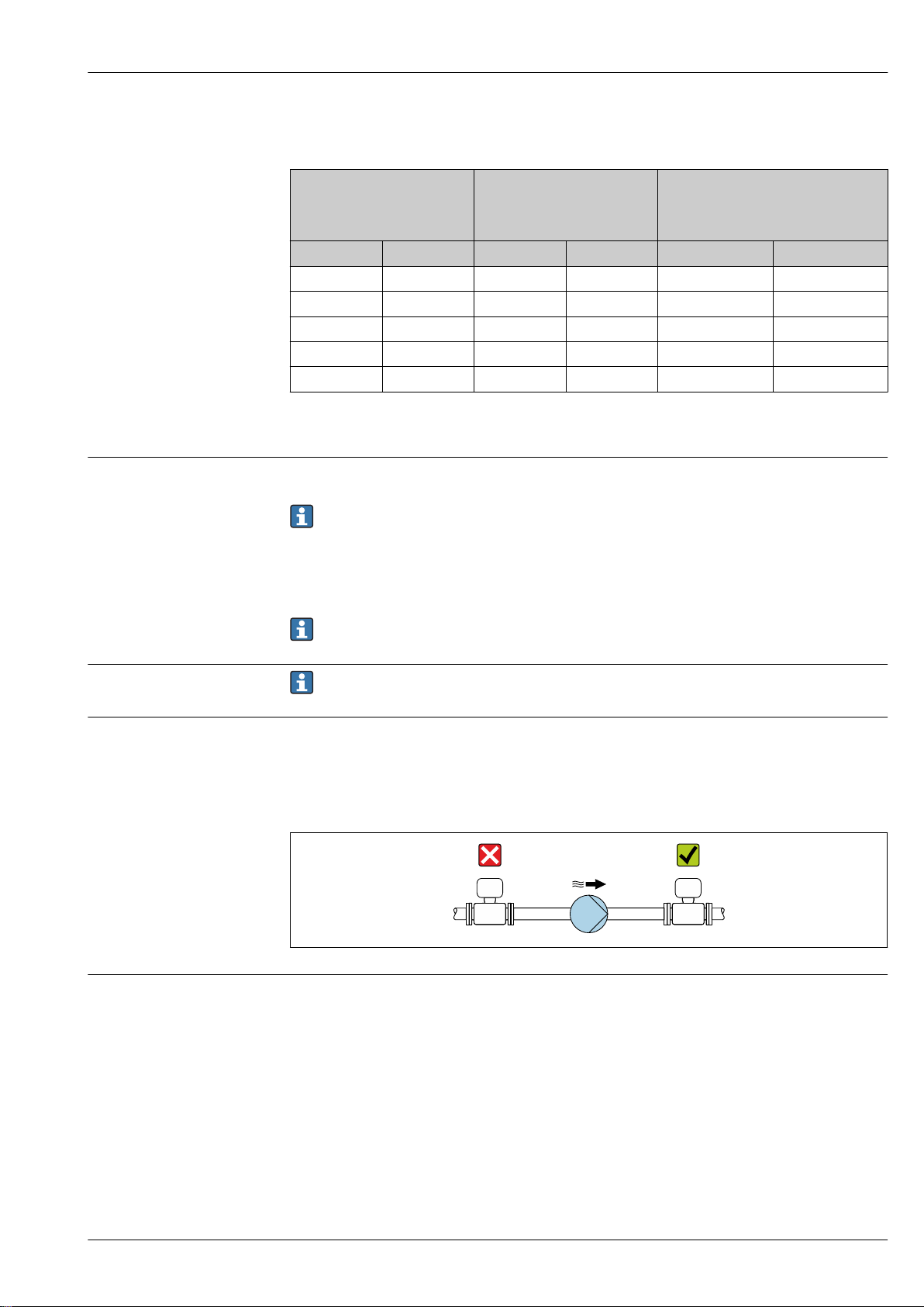
Proline Promass P 300
corresponding type test declaration can be ordered with the device (order code for "Additional
approval", option LN "Sensor housing burst pressure, type test").
Flow limit
DN Sensor housing nominal
pressure
(designed with a safety factor
≥ 4)
[mm] [in] [bar] [psi] [bar] [psi]
8 ³⁄₈ 25 362 190 2 755
15 ½ 25 362 175 2 538
25 1 25 362 165 2 392
40 1½ 25 362 152 2 204
50 2 25 362 103 1 494
Sensor housing burst pressure
For information on the dimensions: see the "Mechanical construction" section→ 57
Select the nominal diameter by optimizing between the required flow range and permissible pressure
loss.
For an overview of the full scale values for the measuring range, see the "Measuring range"
section → 10
• The minimum recommended full scale value is approx. 1/20 of the maximum full scale value
• In most applications, 20 to 50 % of the maximum full scale value can be considered ideal
• A low full scale value must be selected for abrasive media (such as liquids with entrained solids):
flow velocity < 1 m/s (< 3 ft/s).
To calculate the flow limit, use the Applicator sizing tool → 109
Pressure loss
System pressure
Thermal insulation
To calculate the pressure loss, use the Applicator sizing tool → 109
It is important that cavitation does not occur, or that gases entrained in the liquids do not outgas.
This is prevented by means of a sufficiently high system pressure.
For this reason, the following mounting locations are recommended:
• At the lowest point in a vertical pipe
• Downstream from pumps (no danger of vacuum)
A0028777
In the case of some fluids, it is important to keep the heat radiated from the sensor to the
transmitter to a low level. A wide range of materials can be used for the required insulation.
The following device versions are recommended for versions with thermal insulation:
• Version with extended neck for insulation:
Order code for "Sensor option", option CG with an extended neck length of 105 mm (4.13 in).
• Extended temperature version:
Order code for "Measuring tube material", option TD or TG with an extended neck length of
105 mm (4.13 in).
Endress+Hauser 55
Page 56
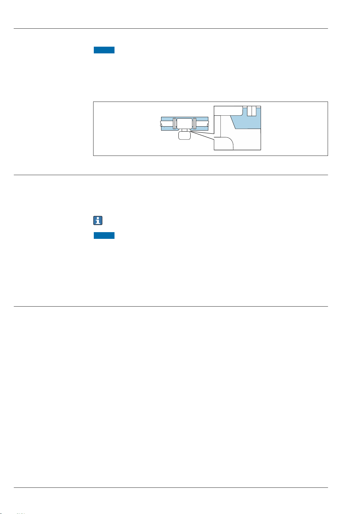
Proline Promass P 300
NOTICE
Electronics overheating on account of thermal insulation!
Recommended orientation: horizontal orientation, transmitter housing pointing downwards.
‣
Do not insulate the transmitter housing .
‣
Maximum permissible temperature at the lower end of the transmitter housing: 80 °C (176 °F)
‣
Thermal insulation with extended neck free: We recommend that you do not insulate the
‣
extended neck in order to ensure optimum dissipation of heat.
33 Thermal insulation with extended neck free
A0034391
Heating
Vibrations
Some fluids require suitable measures to avoid loss of heat at the sensor.
Heating options
• Electrical heating, e.g. with electric band heaters
• Via pipes carrying hot water or steam
• Via heating jackets
Heating jackets for the sensors can be ordered as accessories from Endress+Hauser .→ 108
NOTICE
Danger of overheating when heating
Ensure that the temperature at the lower end of the transmitter housing does not exceed
‣
80 °C (176 °F).
Ensure that sufficient convection takes place at the transmitter neck.
‣
Ensure that a sufficiently large area of the transmitted neck remains exposed. The uncovered
‣
part serves as a radiator and protects the electronics from overheating and excessive cooling.
If using in potentially explosive atmospheres, observe the information in the device-specific Ex
‣
documentation. For detailed information on the temperature tables, see the separate document
entitled "Safety Instructions" (XA) for the device.
The high oscillation frequency of the measuring tubes ensures that the correct operation of the
measuring system is not influenced by plant vibrations.
56 Endress+Hauser
Page 57
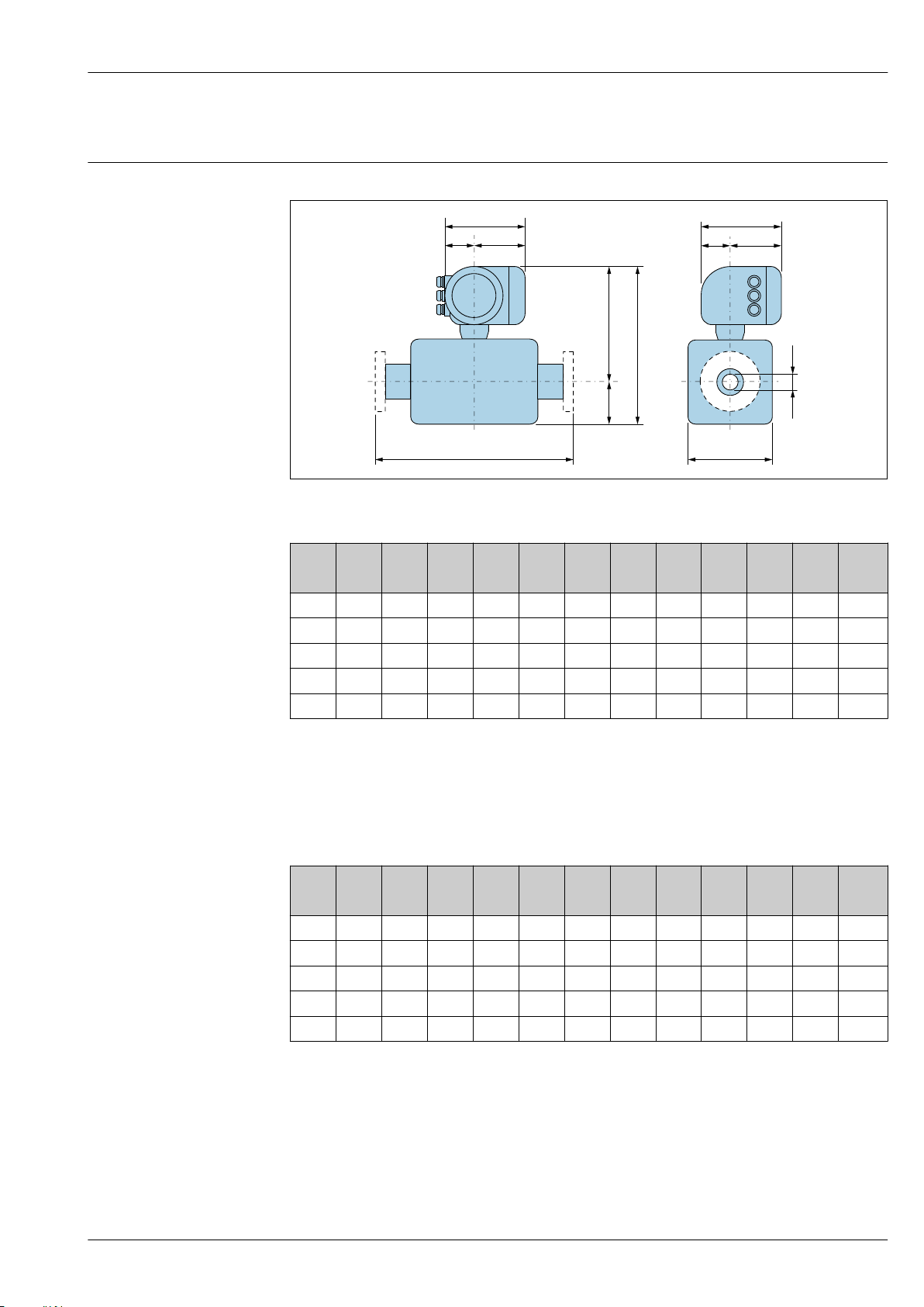
Proline Promass P 300
D
L
E
F
A
CB
K
G
H
I
M
Mechanical construction
Dimensions in SI units Compact version
A0033783
Order code for "Housing", option A "Aluminum, coated"
DN A
1)
B
C D E
2)
2)
F
3)
G
H I
3)
K L M
1)
[mm] [mm] [mm] [mm] [mm] [mm] [mm] [mm] [mm] [mm] [mm] [mm] [mm]
8 169 68 101 108 266 374 200 59 141 8.30
15 169 68 101 108 266 374 200 59 141 12.0
25 169 68 101 121 266 387 200 59 141 17.6
40 169 68 101 178 297 475 200 59 141 26.0
50 169 68 101 262 310 572 200 59 141 38.0
4)
92
4)
92
4)
92
4)
142
4)
169
1) Depending on the cable gland used: values up to + 30 mm
2) With order code for "Sensor option", option CG or order code for "Measuring tube material", option TD, TG:
values +70 mm
3) For version without local display: values - 30 mm
4) Depends on the process connection in question
Order code for "Housing", option A "Aluminum, coated"; Ex d
DN A
1)
B C D E
[mm] [mm] [mm] [mm] [mm] [mm] [mm] [mm] [mm] [mm] [mm] [mm] [mm]
8 188 85 103 108 278 404 206 58 148 8.30
15 188 85 103 108 278 404 206 58 148 12.0
25 188 85 103 121 278 417 206 58 148 17.6
40 188 85 103 178 308 505 206 58 148 26.0
50 188 85 103 262 322 602 206 58 148 38.0
2)
2)
F
3)
G
H I
3)
K L M
4)
92
4)
92
4)
92
4)
142
4)
169
1) Depending on the cable gland used: values up to + 30 mm
2) With order code for "Sensor option", option CG or order code for "Measuring tube material", option TD, TG:
values +70 mm
3) For version without local display: values - 38 mm
4) Depends on the process connection in question
Endress+Hauser 57
Page 58
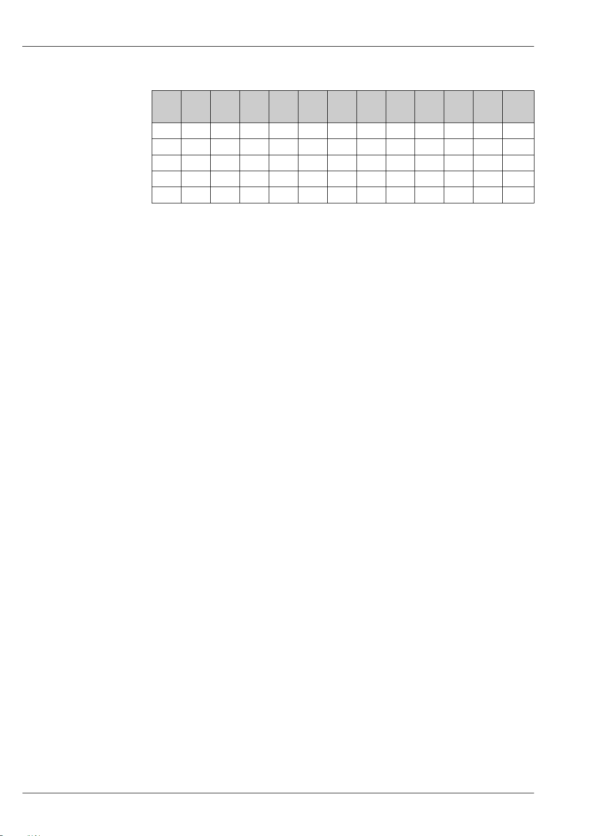
Proline Promass P 300
Order code for "Housing", option B "Stainless, hygienic"
DN A
1)
B C D E
[mm] [mm] [mm] [mm] [mm] [mm] [mm] [mm] [mm] [mm] [mm] [mm] [mm]
8 183 73 110 108 266 374 207 65 142 8.30
15 183 73 110 108 266 374 207 65 142 12.0
25 183 73 110 121 266 387 207 65 142 17.6
40 183 73 110 178 297 475 207 65 142 26.0
50 183 73 110 262 310 572 207 65 142 38.0
1) Depending on the cable gland used: values up to + 30 mm
2) With order code for "Sensor option", option CG or order code for "Measuring tube material", option TD, TG:
values +70 mm
3) Depends on the process connection in question
2)
2)
F
G H I K L M
3)
92
3)
92
3)
92
3)
142
3)
169
58 Endress+Hauser
Page 59
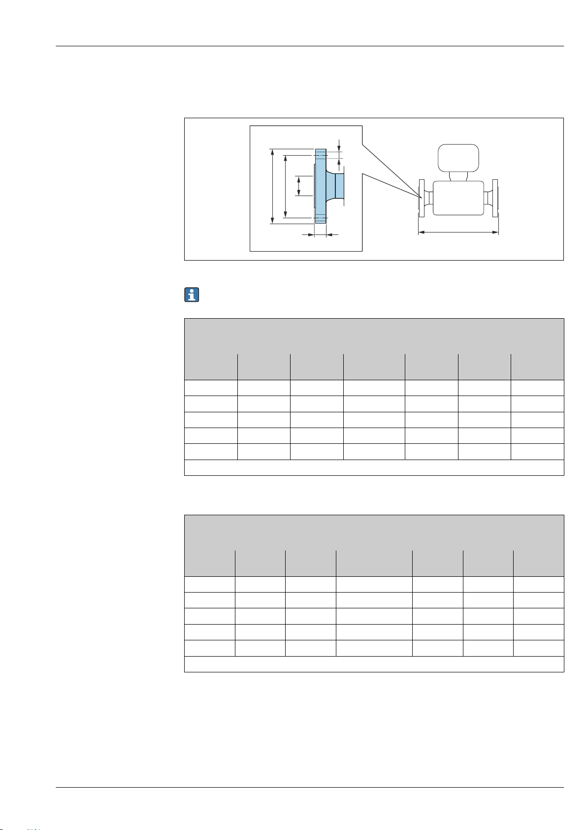
Proline Promass P 300
C
D
A
B
E
L
Flange connections
Fixed flange EN 1092-1, ASME B16.5, JIS B2220
A0015621
Length tolerance for dimension L in mm:
+1.5 / –2.0
Flange according to EN 1092-1 (DIN 2501): PN 40
1.4404 (316/316L)
Order code for "Process connection", option D2W
DN
[mm]
1)
8
15 95 65 4 × Ø14 20.0 17.3 440
25 115 85 4 × Ø14 19.0 28.5 580
40 150 110 4 × Ø18 21.0 43.1 707
50 165 125 4 × Ø18 25.0 54.5 828
Surface roughness (flange): EN 1092-1 Form B1 (DIN 2526 Form C), Ra 3.2 to 12.5 µm
1) DN 8 with DN 15 flanges as standard
Flange according to ASME B16.5: Cl 150
1.4404 (316/316L)
Order code for "Process connection", option AAW
DN
[mm]
1)
8
15 90 60.3 4 × Ø15.7 11.2 15.7 440
25 110 79.4 4 × Ø15.7 14.2 26.7 580
40 125 98.4 4 × Ø15.7 17.5 40.9 707
50 150 120.7 8 × Ø19.1 19.1 52.6 828
Surface roughness (flange): Ra 3.2 to 6.3 µm
A
[mm]
95 65 4 × Ø14 17.0 17.3 336
A
[mm]
90 60.3 4 × Ø15.7 11.2 15.7 336
[mm]
B
[mm]
B
C
[mm]
C
[mm]
D
[mm]
[mm]
E
[mm]
D
E
[mm]
L
[mm]
L
[mm]
1) DN 8 with DN 15 flanges as standard
Endress+Hauser 59
Page 60
Proline Promass P 300
Flange JIS B2220: 20K
1.4404 (316/316L)
Order code for "Process connection", option NEW
DN
[mm]
1)
8
15 95 70 4 × Ø15 16.0 15 440
25 125 90 4 × Ø19 17.5 25 580
40 140 105 4 × Ø19 20.0 40 707
50 155 120 8 × Ø19 27.5 50 828
Surface roughness (flange): Ra 3.2 to 6.3 µm
1) DN 8 with DN 15 flanges as standard
A
[mm]
95 70 4 × Ø15 16.0 15 336
B
[mm]
C
[mm]
D
[mm]
E
[mm]
L
[mm]
60 Endress+Hauser
Page 61
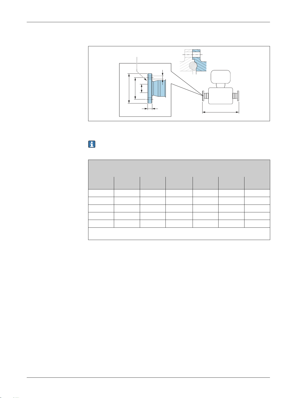
Proline Promass P 300
C
D
A
B
E
X X
L
Fixed flange DIN 11864-2
A0015627
34 Detail X: Asymmetrical process connection; the part shown in blue is provided by the supplier.
Length tolerance for dimension L in mm:
+1.5 / –2.0
Flange DIN 11864-2 Form A, for pipe according to DIN 11866 series A, flange with notch
1.4435 (316L)
Order code for "Process connection", option KJW
DN
[mm]
8 59.0 42 4 × Ø9 10 16.00 384
15 59.0 42 4 × Ø9 10 16.00 488
25 70.0 53 4 × Ø9 10 26.00 626
40 82.0 65 4 × Ø9 10 38.00 753
50 94.0 77 4 × Ø9 10 50.00 877
Ra
0.76 µm: order code for "Measuring tube material", option BB, TD
max
Ra
0.38 µm electropolished: order code for "Measuring tube material", option BC, TG
max
A
[mm]
B
[mm]
C
[mm]
D
[mm]
E
[mm]
L
[mm]
Endress+Hauser 61
Page 62
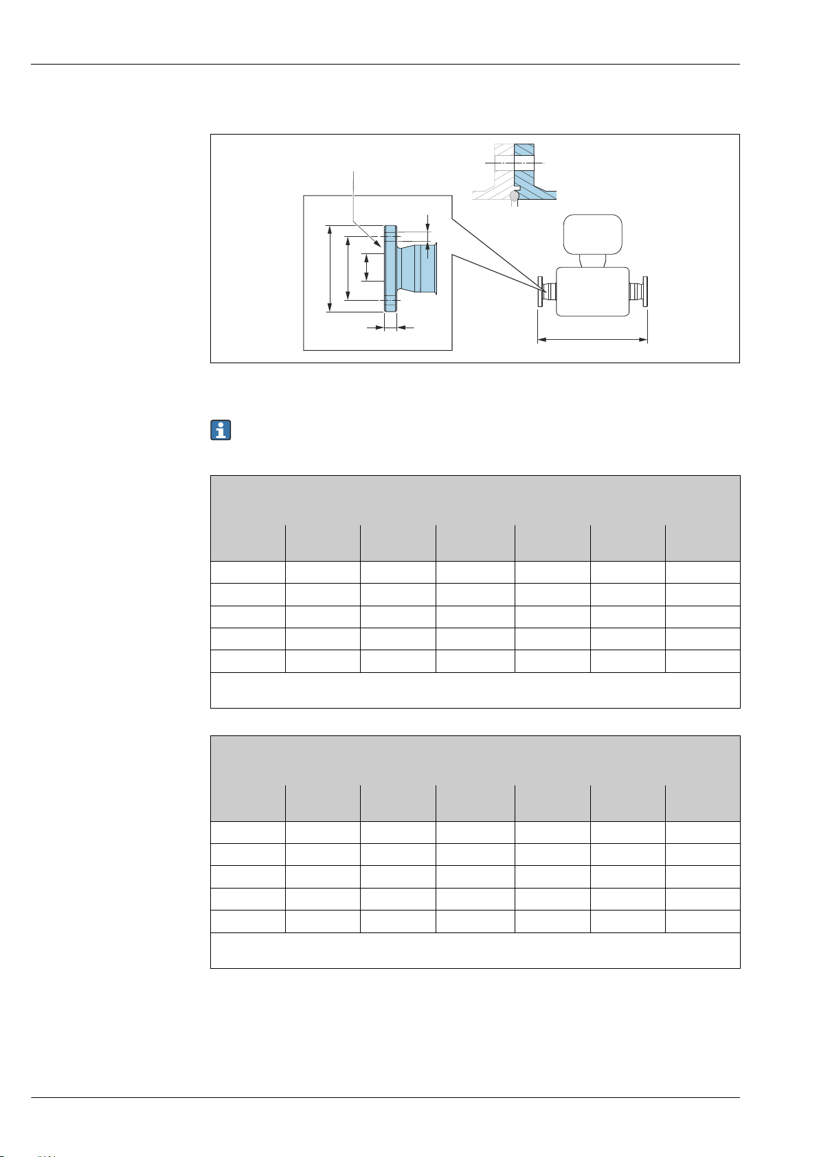
Proline Promass P 300
L
C
D
A
B
E
XX
BBS fixed flange
35 Detail X: Asymmetrical process connection; the part shown in blue is provided by the supplier.
Length tolerance for dimension L in mm:
+1.5 / –2.0
A0016910
BBS flange small (sterile orbital), for pipe according to DIN 11866 series A, female
1.4435 (316L)
Order code for "Process connection", option BSK
DN
[mm]
8 59 42 4 × Ø9 10 10.00 384
15 59 42 4 × Ø9 10 16.00 488
25 70 53 4 × Ø9 10 26.00 626
40 82 65 4 × Ø9 10 38.00 753
50 94 77 4 × Ø9 10 50.00 877
Ra
0.76 µm: order code for "Measuring tube material", option BB, TD
max
Ra
0.38 µm electropolished: order code for "Measuring tube material", option BC, TG
max
BBS flange small (sterile orbital), for pipe according to DIN 11866 series B, female
1.4435 (316L)
Order code for "Process connection", option BSL
DN
[mm]
8 59 42 4 × Ø9 10 14.00 384
15 62 45 4 × Ø9 10 18.10 488
25 74 57 4 × Ø9 10 29.70 626
40 88 71 4 × Ø9 10 44.30 753
50 103 85 4 × Ø9 10 56.30 877
Ra
0.76 µm: order code for "Measuring tube material", option BB, TD
max
Ra
0.38 µm electropolished: order code for "Measuring tube material", option BC, TG
max
A
[mm]
A
[mm]
B
[mm]
B
[mm]
C
[mm]
C
[mm]
D
[mm]
D
[mm]
E
[mm]
E
[mm]
L
[mm]
L
[mm]
62 Endress+Hauser
Page 63
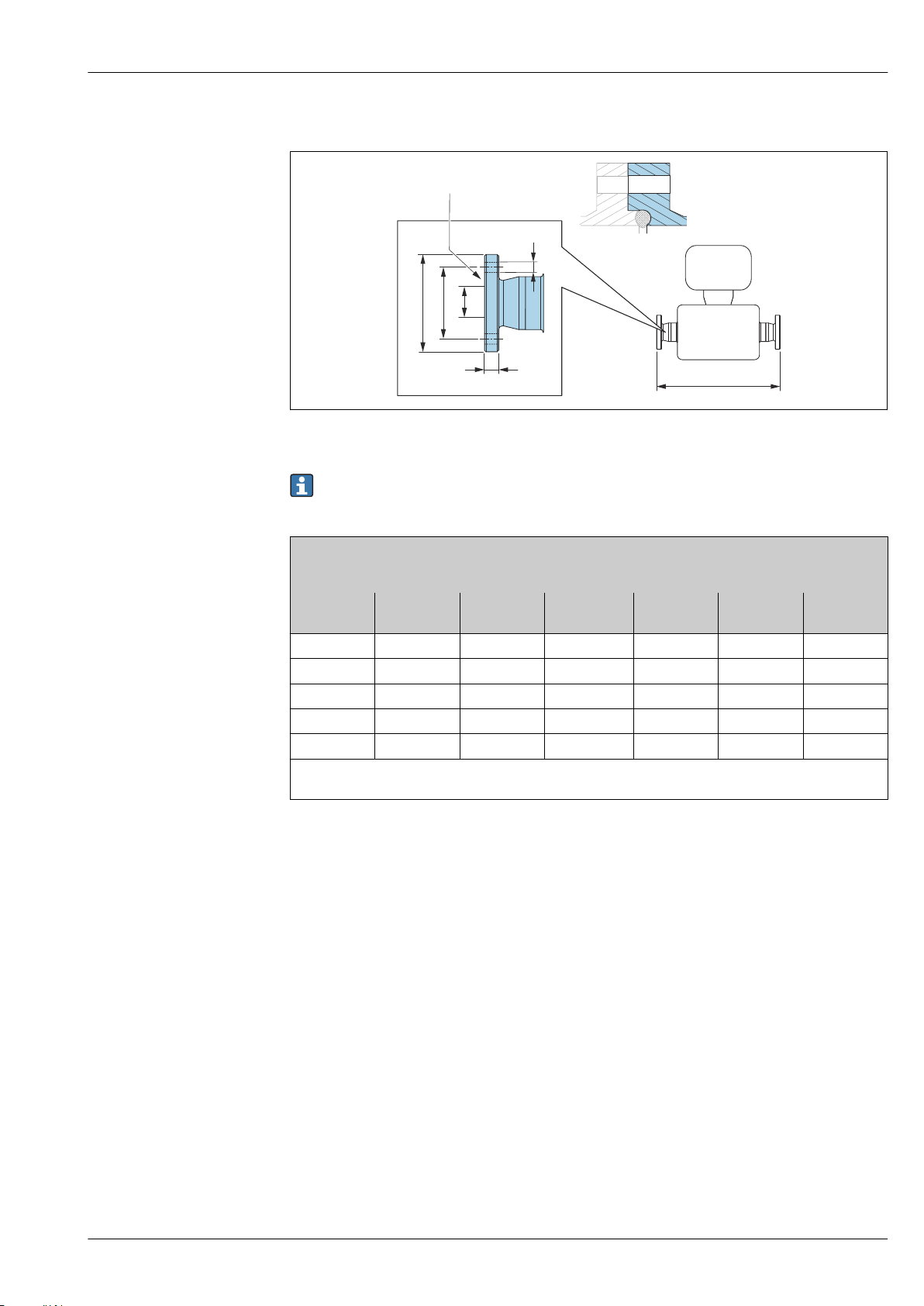
Proline Promass P 300
L
C
D
A
B
E
XX
Neumo BioConnect fixed flange
A0016907
36 Detail X: Asymmetrical process connection; the part shown in blue is provided by the supplier.
Length tolerance for dimension L in mm:
+1.5 / –2.0
Neumo BioConnect flange (sterile orbital), for pipe according to DIN 11866 series A, flange form R
1.4435 (316L)
Order code for "Process connection", option BSB
DN
[mm]
8 65 45 4 × Ø9 10 10.00 384
15 75 55 4 × Ø9 10 16.00 488
25 85 65 4 × Ø9 12 26.00 626
40 100 80 4 × Ø9 12 38.00 753
50 110 90 4 × Ø9 14 50.00 877
Ra
0.76 µm: order code for "Measuring tube material", option BB, TD
max
Ra
0.38 µm electropolished: order code for "Measuring tube material", option BC, TG
max
A
[mm]
B
[mm]
C
[mm]
D
[mm]
E
[mm]
L
[mm]
Endress+Hauser 63
Page 64
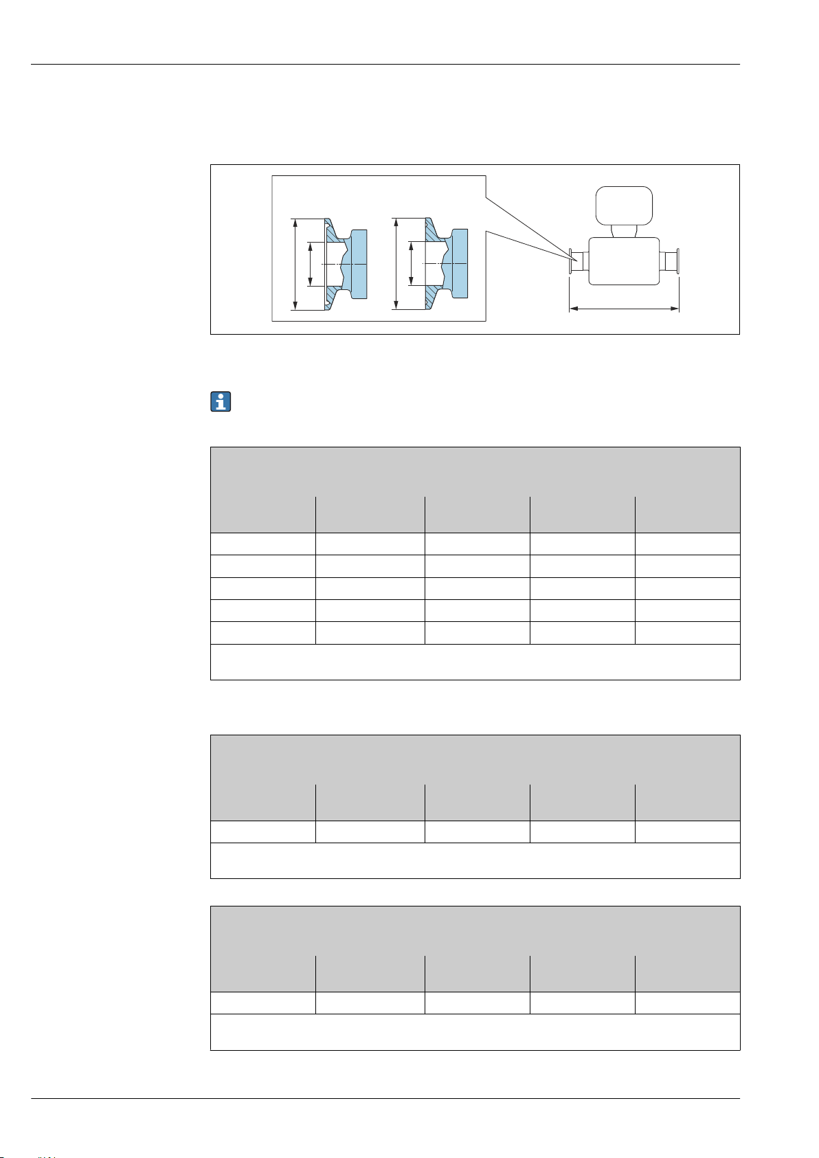
Clamp connections
L
A
B
≥ (1")DN 25DN 8, 15 (¾", ½")
A
B
Tri-Clamp
37 Engineering unit mm (in)
Length tolerance for dimension L in mm:
+1.5 / –2.0
Proline Promass P 300
A0023342
Tri-Clamp, for pipe according to DIN 11866 series C
1.4435 (316L)
Order code for "Process connection", option FHW
DN
[mm]
Clamp
[in]
A
[mm]
B
[mm]
8 ½ 25.0 9.40 362
15 ¾ 25.0 15.75 466
25 1
40 1½
50 2
Ra
0.76 µm: order code for "Measuring tube material", option BB, TD
max
Ra
0.38 µm electropolished: order code for "Measuring tube material", option BC, TG
max
1)
1)
1)
50.4 22.10 606
50.4 34.80 731
63.9 47.50 853
1) The connection complies with the hygienic clamp dimensions as per ASME BPE.
½" Tri-Clamp, for pipe according to DIN 11866 series C
1.4435 (316L)
Order code for "Process connection", option FCW
DN
[mm]
Clamp
[in]
A
[mm]
B
[mm]
15 ½ 25.0 9.40 466
Ra
0.76 µm: order code for "Measuring tube material", option BB, TD
max
Ra
0.38 µm electropolished: order code for "Measuring tube material", option BC, TG
max
L
[mm]
L
[mm]
¾" Tri-Clamp, for pipe according to DIN 11866 series C
1.4435 (316L)
Order code for "Process connection", option FFW
DN
[mm]
Clamp
[in]
A
[mm]
B
[mm]
L
[mm]
8 ¾ 25.0 15.75 362
Ra
0.76 µm: order code for "Measuring tube material", option BB, TD
max
Ra
0.38 µm electropolished: order code for "Measuring tube material", option BC, TG
max
64 Endress+Hauser
Page 65
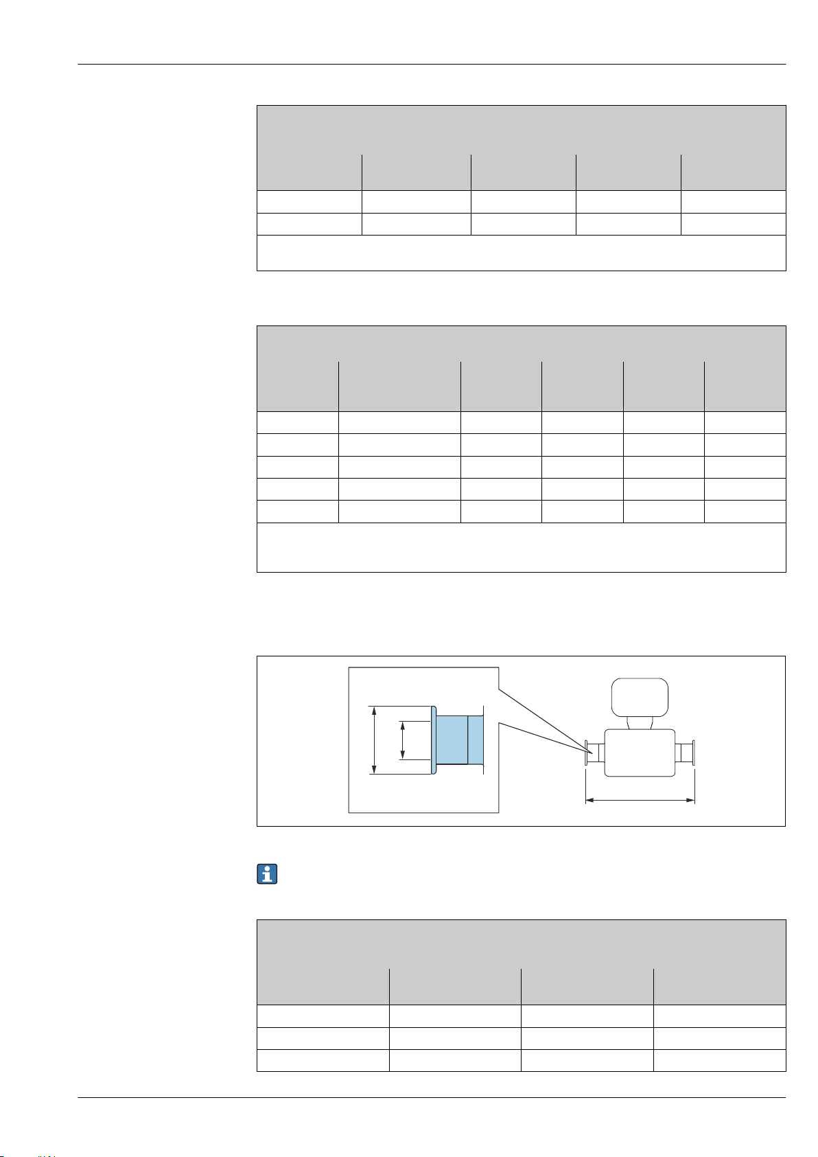
Proline Promass P 300
L
A
B
1" Tri-Clamp, for pipe according to DIN 11866 series C
1.4435 (316L)
Order code for "Process connection", option FPW
DN
[mm]
8 1
15 1
Ra
0.76 µm: order code for "Measuring tube material", option BB, TD
max
Ra
0.38 µm electropolished: order code for "Measuring tube material", option BC, TG
max
Clamp
[in]
1)
1)
A
[mm]
B
[mm]
50.4 22.10 362
50.4 22.10 466
1) The connection complies with the hygienic clamp dimensions as per ASME BPE.
Tri-Clamp eccentric, for pipe according to DIN 11866 series C
1.4435 (316L)
DN
[mm]
Order code for
"Process connection",
Clamp
[in]
A
[mm]
B
[mm]
option
8 FEB ½ 25.0 9.40 362
15 FED ¾ 25.0 15.75 466
25 FEF 1
40 FEH 1½
50 FEK 2
Ra
0.76 µm: order code for "Measuring tube material", option BB, TD
max
Ra
0.38 µm electropolished: order code for "Measuring tube material", option BC, TG
max
1)
1)
1)
50.4 22.10 606
50.4 34.80 738
63.9 47.50 860
Additional information on "Eccentric clamps"
L
[mm]
L
[mm]
1) The connection complies with the hygienic clamp dimensions as per ASME BPE.
Clamp connection DIN 32676, ISO 2852
A0015625
Length tolerance for dimension L in mm:
+1.5 / –2.0
Clamp DIN 32676, for pipe according to DIN 11866 series A
1.4435 (316L)
Order code for "Process connection", option KPW
DN
[mm]
8 34.0 16.00 362
15 34.0 16.00 466
25 50.5 26.00 606
A
[mm]
B
[mm]
L
[mm]
Endress+Hauser 65
Page 66
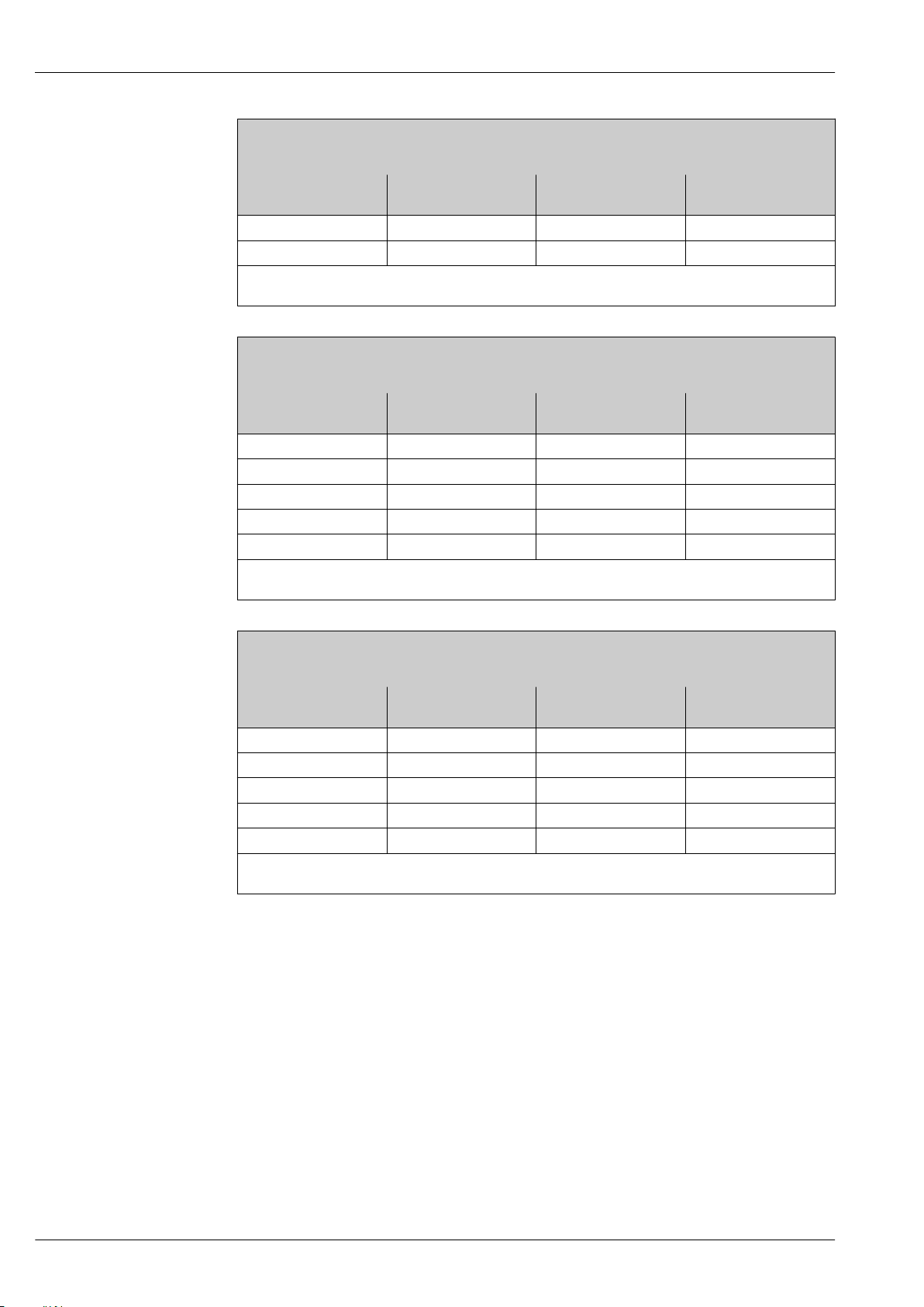
Clamp DIN 32676, for pipe according to DIN 11866 series A
1.4435 (316L)
Order code for "Process connection", option KPW
DN
[mm]
A
[mm]
B
[mm]
40 50.5 38.00 732
50 64.0 50.00 854
Ra
0.76 µm: order code for "Measuring tube material", option BB, TD
max
Ra
0.38 µm electropolished: order code for "Measuring tube material", option BC, TG
max
Clamp ISO 2852 , for pipe according to ISO 2037
1.4435 (316L)
Order code for "Process connection", option JSA
DN
[mm]
A
[mm]
B
[mm]
8 50.5 22.6 362
15 50.5 22.6 466
25 50.5 22.6 606
40 50.5 35.6 731
50 64.0 48.6 853
Ra
0.76 µm: order code for "Measuring tube material", option BB, TD
max
Ra
0.38 µm electropolished: order code for "Measuring tube material", option BC, TG
max
Proline Promass P 300
L
[mm]
L
[mm]
Clamp ISO 2852, for pipe according to DIN11866 series B
1.4435 (316L)
Order code for "Process connection", option JSC
DN
[mm]
A
[mm]
B
[mm]
8 34.0 14.00 362
15 34.0 18.10 466
25 50.5 29.70 606
40 64.0 44.30 731
50 77.5 56.30 853
Ra
0.76 µm: order code for "Measuring tube material", option BB, TD
max
Ra
0.38 µm electropolished: order code for "Measuring tube material", option BC, TG
max
L
[mm]
66 Endress+Hauser
Page 67
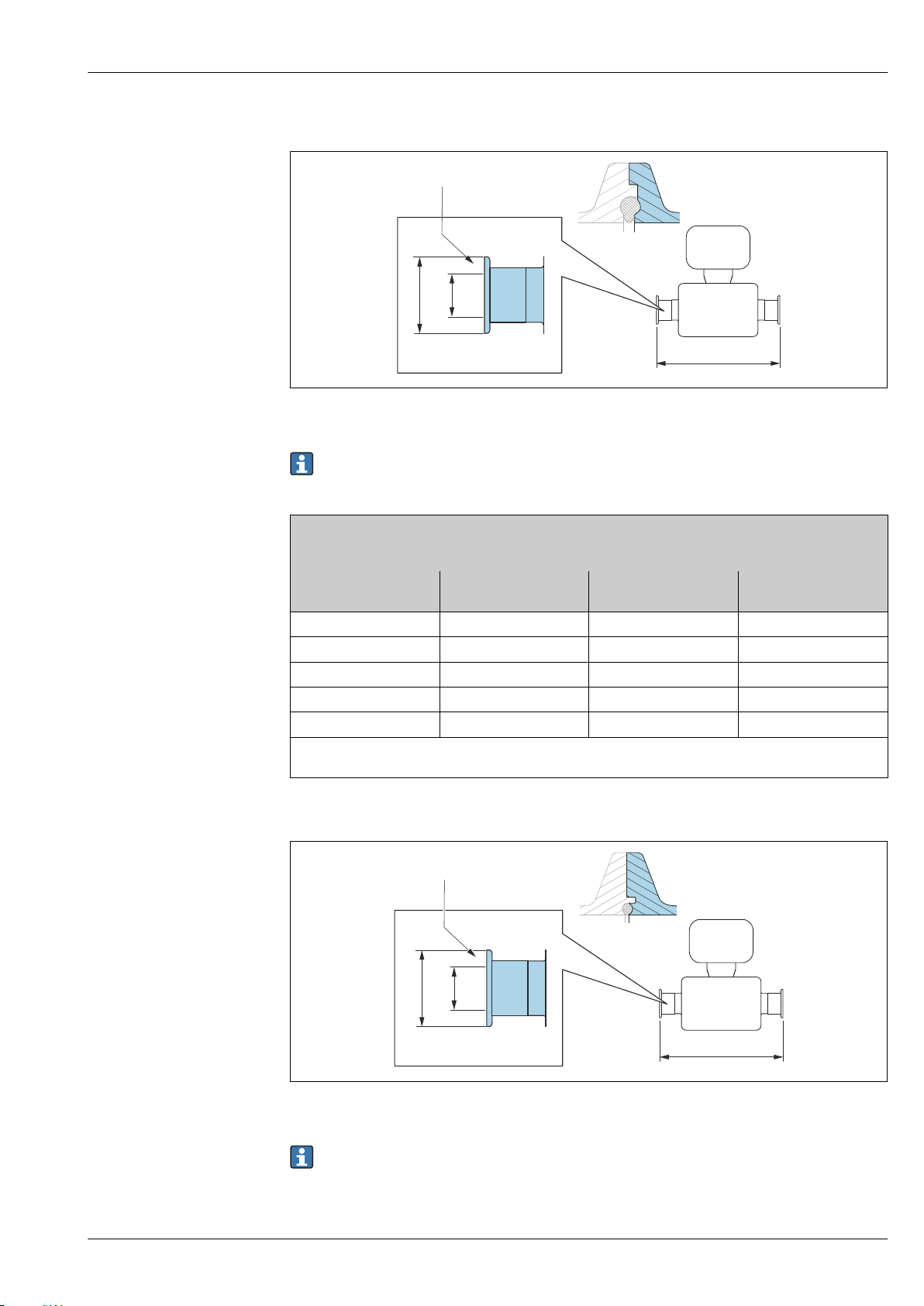
Proline Promass P 300
A
B
X
L
X
L
X
A
B
X
Clamp connection DIN 11864-3
A0016903
38 Detail X: Asymmetrical process connection; the part shown in blue is provided by the supplier.
Length tolerance for dimension L in mm:
+1.5 / –2.0
Clamp DIN 11864-3 Form A, with notch, for pipe according to DIN 11866 series A
1.4435 (316L)
Order code for "Process connection", option KLW
DN
[mm]
8 34.0 16.05 370
15 34.0 16.05 474
25 50.5 26.05 614
40 64.0 38.05 738
50 77.5 50.05 853
Ra
0.76 µm: order code for "Measuring tube material", option BB, TD
max
Ra
0.38 µm electropolished: order code for "Measuring tube material", option BC, TG
max
A
[mm]
B
[mm]
BBS clamp connection
L
[mm]
A0016908
39 Detail X: Asymmetrical process connection; the part shown in blue is provided by the supplier.
Length tolerance for dimension L in mm:
+1.5 / –2.0
Endress+Hauser 67
Page 68
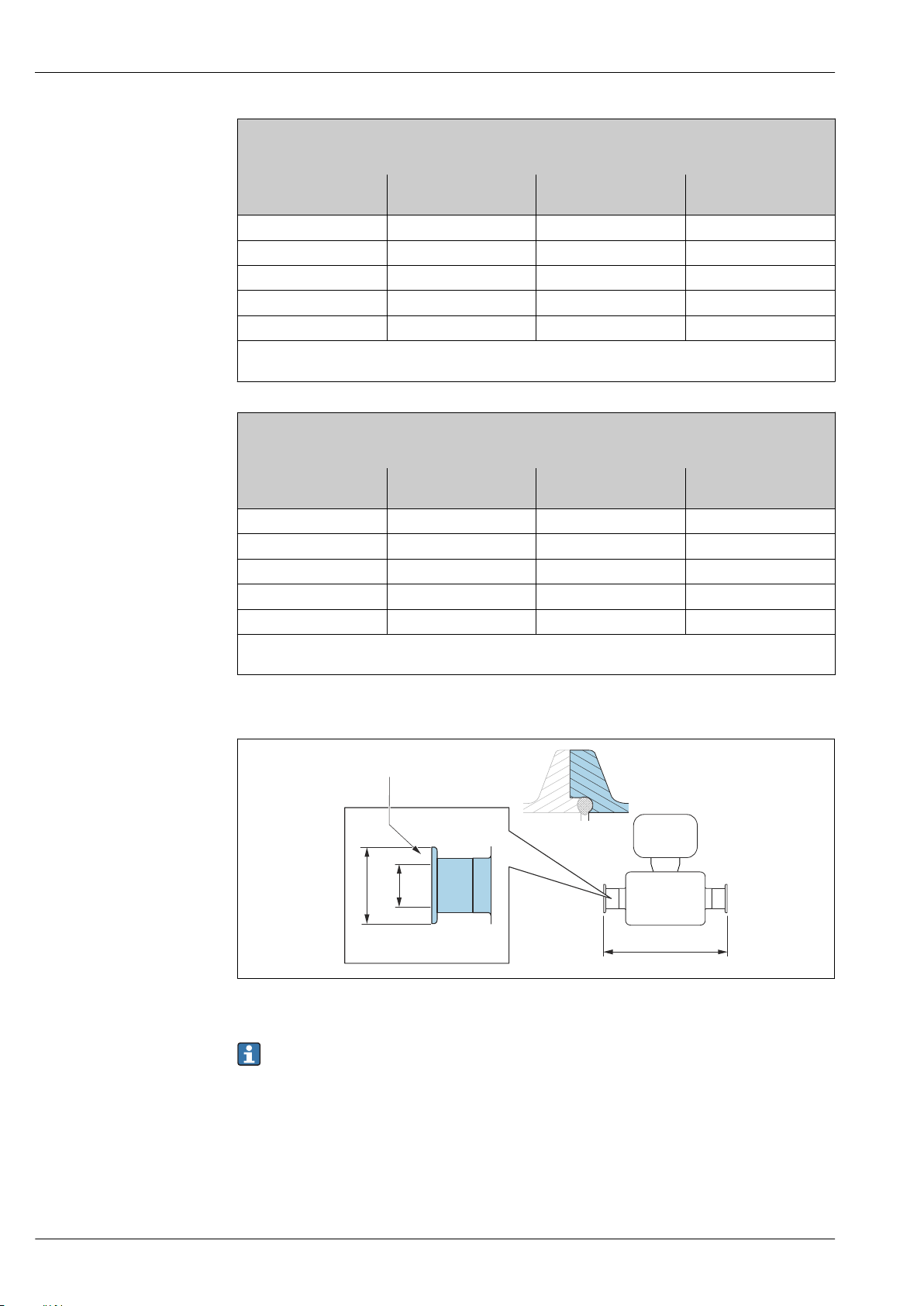
Proline Promass P 300
L
X
A
B
X
BBS Quick Connect (sterile orbital), for pipe according to DIN 11866 series A, female
1.4435 (316L)
Order code for "Process connection", option BSE
DN
[mm]
8 25.0 10.00 362
15 50.5 16.00 466
25 50.5 26.00 606
40 64.0 38.00 732
50 77.5 50.00 854
Ra
0.76 µm: order code for "Measuring tube material", option BB, TD
max
Ra
0.38 µm electropolished: order code for "Measuring tube material", option BC, TG
max
BBS Quick Connect (sterile orbital) for pipe according to DIN11866 series B, female
1.4435 (316L)
Order code for "Process connection", option BSJ
DN
[mm]
8 25.0 14.00 362
15 50.5 18.10 466
25 50.5 29.70 606
40 64.0 44.30 738
50 77.5 56.30 860
Ra
0.76 µm: order code for "Measuring tube material", option BB, TD
max
Ra
0.38 µm electropolished: order code for "Measuring tube material", option BC, TG
max
A
[mm]
A
[mm]
B
[mm]
B
[mm]
L
[mm]
L
[mm]
Neumo BioConnect clamp connection
A0016905
40 Detail X: Asymmetrical process connection; the part shown in blue is provided by the supplier.
Length tolerance for dimension L in mm:
+1.5 / –2.0
68 Endress+Hauser
Page 69
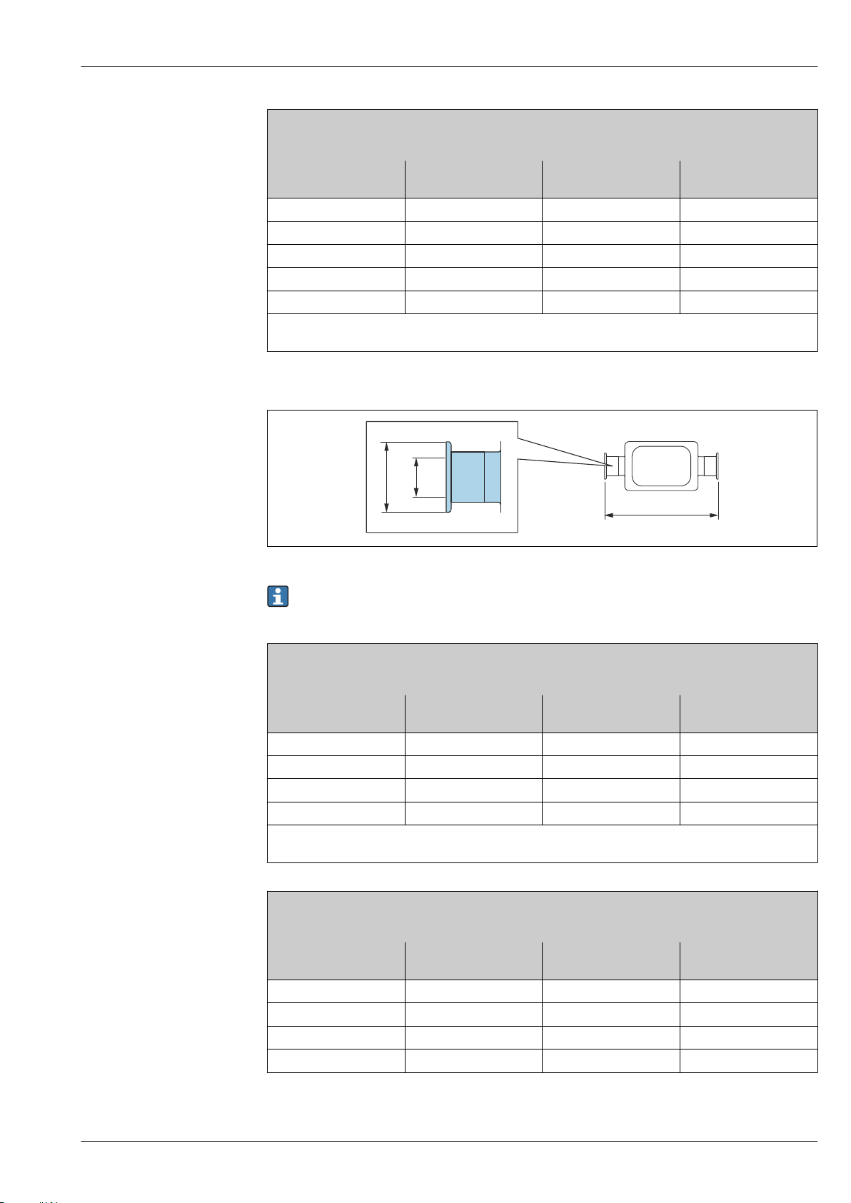
Proline Promass P 300
L
A
B
Clamp, Neumo BioConnect (sterile orbital), for pipe according to DIN 11866 series A, clamp form R
1.4435 (316L)
Order code for "Process connection", option BSA
DN
[mm]
A
[mm]
B
[mm]
L
[mm]
8 25.0 10.00 362
15 25.0 16.00 466
25 50.4 26.00 606
40 64.0 38.00 732
50 77.4 50.00 854
Ra
0.76 µm: order code for "Measuring tube material", option BB, TD
max
Ra
0.38 µm electropolished: order code for "Measuring tube material", option BC, TG
max
Eccentric clamp connection DIN 32676, ISO 2852
Length tolerance for dimension L in mm:
+1.5 / –2.0
Eccentric clamp DIN 32676, for pipe according to DIN 11866 series A
1.4435 (316L)
Order code for "Process connection", option KRW
DN
[mm]
8 34.0 10.00 362
15 34.0 16.00 466
25 50.5 26.00 606
50 64.0 50.00 860
Ra
0.76 µm: order code for "Measuring tube material", option BB, TD
max
Ra
0.38 µm electropolished: order code for "Measuring tube material", option BC, TG
max
Eccentric clamp ISO 2852, for pipe according to DIN11866 series B
1.4435 (316L)
Order code for "Process connection", option JEC
DN
[mm]
8 34.0 10.30 362
15 34.0 14.00 466
25 34.0 18.10 606
40 50.5 29.70 738
A
[mm]
A
[mm]
B
[mm]
B
[mm]
A0016543
L
[mm]
L
[mm]
Endress+Hauser 69
Page 70
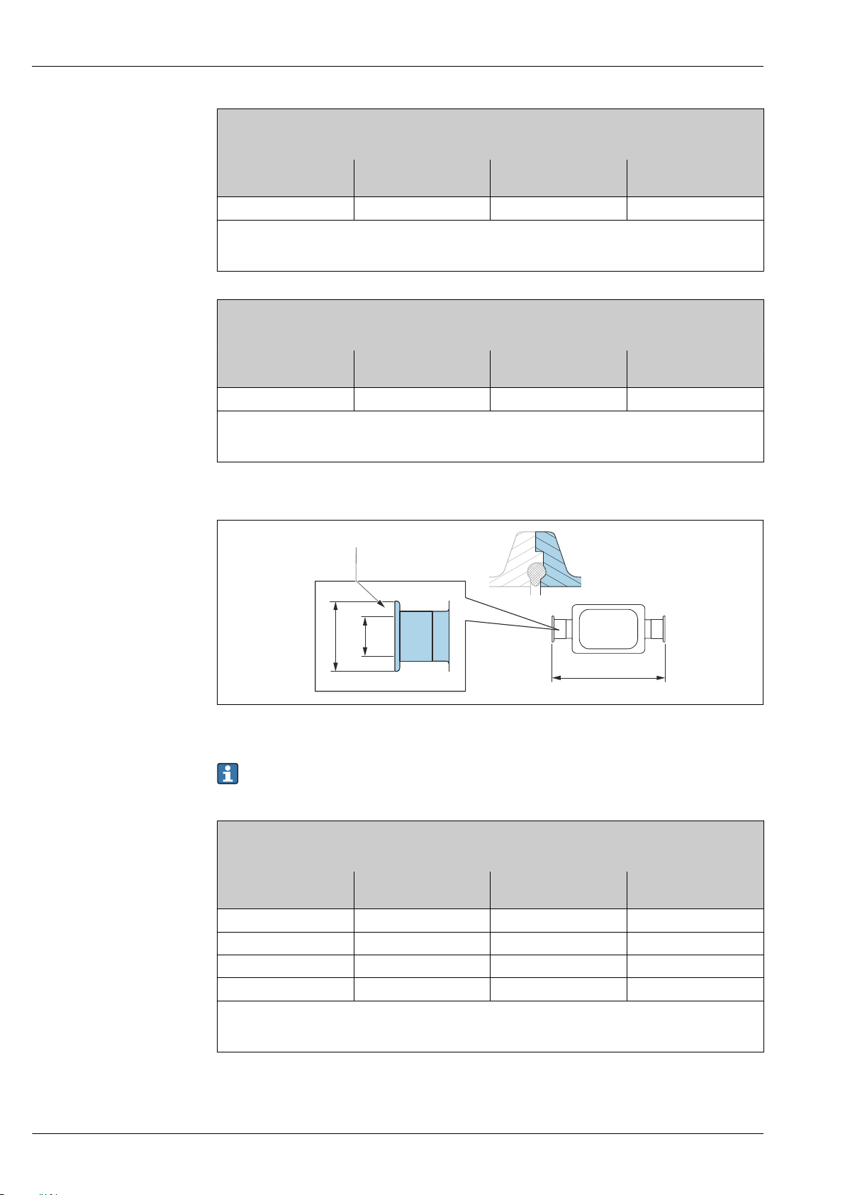
Proline Promass P 300
X
L
A
B
X
Eccentric clamp ISO 2852, for pipe according to DIN11866 series B
1.4435 (316L)
Order code for "Process connection", option JEC
DN
[mm]
50 64.0 44.30 853
Ra
0.76 µm: order code for "Measuring tube material", option BB, TD
max
Ra
0.38 µm electropolished: order code for "Measuring tube material", option BC, TG
max
Additional information on "Eccentric clamps"
Eccentric clamp ISO 2852, for pipe according to DIN11866 series B, for connection to DN15 pipes
1.4435 (316L)
Order code for "Process connection", option JED
DN
[mm]
25 50.5 18.10 606
Ra
0.76 µm: order code for "Measuring tube material", option BB, TD
max
Ra
0.38 µm electropolished: order code for "Measuring tube material", option BC, TG
max
Additional information on "Eccentric clamps"
A
[mm]
A
[mm]
B
[mm]
B
[mm]
L
[mm]
L
[mm]
Eccentric clamp connection DIN 11864-3
A0016904
41 Detail X: Asymmetrical process connection; the part shown in blue is provided by the supplier.
Length tolerance for dimension L in mm:
+1.5 / –2.0
Eccentric clamp DIN 11864-3 Form A, with notch, for pipe according to DIN 11866 series A
1.4435 (316L)
Order code for "Process connection", option KNW
DN
[mm]
8 34.0 10.00 370
15 34.0 16.00 474
25 50.5 26.00 624
50 77.5 50.00 869
Ra
0.76 µm: order code for "Measuring tube material", option BB, TD
max
Ra
0.38 µm electropolished: order code for "Measuring tube material", option BC, TG
max
Additional information on "Eccentric clamps"
A
[mm]
B
[mm]
L
[mm]
70 Endress+Hauser
Page 71
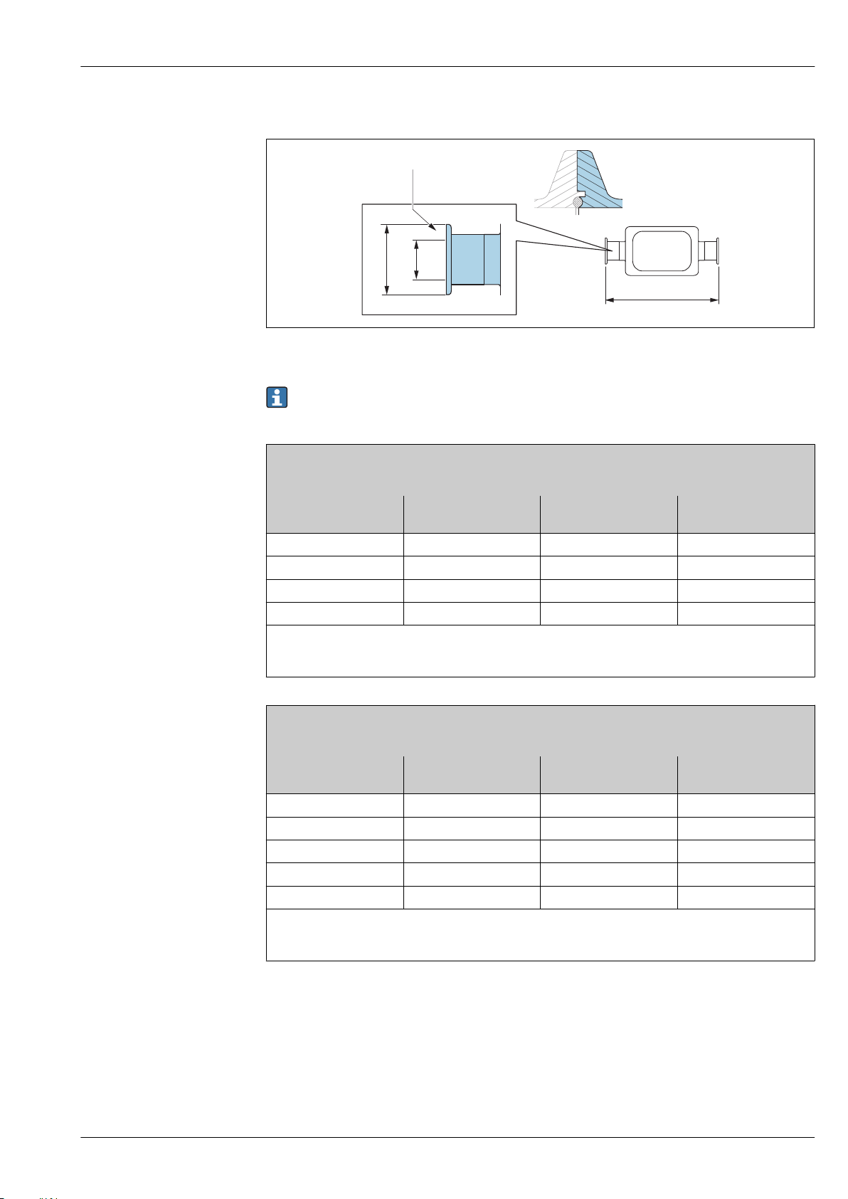
Proline Promass P 300
X
L
A
B
X
BBS eccentric clamp connection
42 Detail X: Asymmetrical process connection; the part shown in blue is provided by the supplier.
Length tolerance for dimension L in mm:
+1.5 / –2.0
BBS Quick Connect (sterile orbital), eccentric, for pipe according to DIN11866 series A, female
1.4435 (316L)
Order code for "Process connection", option BEJ
DN
[mm]
8 25.0 10.00 362
15 50.5 16.00 466
25 50.5 26.00 606
50 77.5 50.00 860
Ra
0.76 µm: order code for "Measuring tube material", option BB, TD
max
Ra
0.38 µm electropolished: order code for "Measuring tube material", option BC, TG
max
Additional information on "Eccentric clamps"
A
[mm]
B
[mm]
[mm]
A0016909
L
BBS Quick Connect (sterile orbital), eccentric, for pipe according to DIN11866 series B, female
1.4435 (316L)
Order code for "Process connection", option BEK
DN
[mm]
A
[mm]
B
[mm]
L
[mm]
8 25.0 10.30 362
15 50.5 14.00 466
25 50.5 18.10 606
40 50.5 29.70 738
50 64.0 44.30 860
Ra
0.76 µm: order code for "Measuring tube material", option BB, TD
max
Ra
0.38 µm electropolished: order code for "Measuring tube material", option BC, TG
max
Additional information on "Eccentric clamps"
Endress+Hauser 71
Page 72
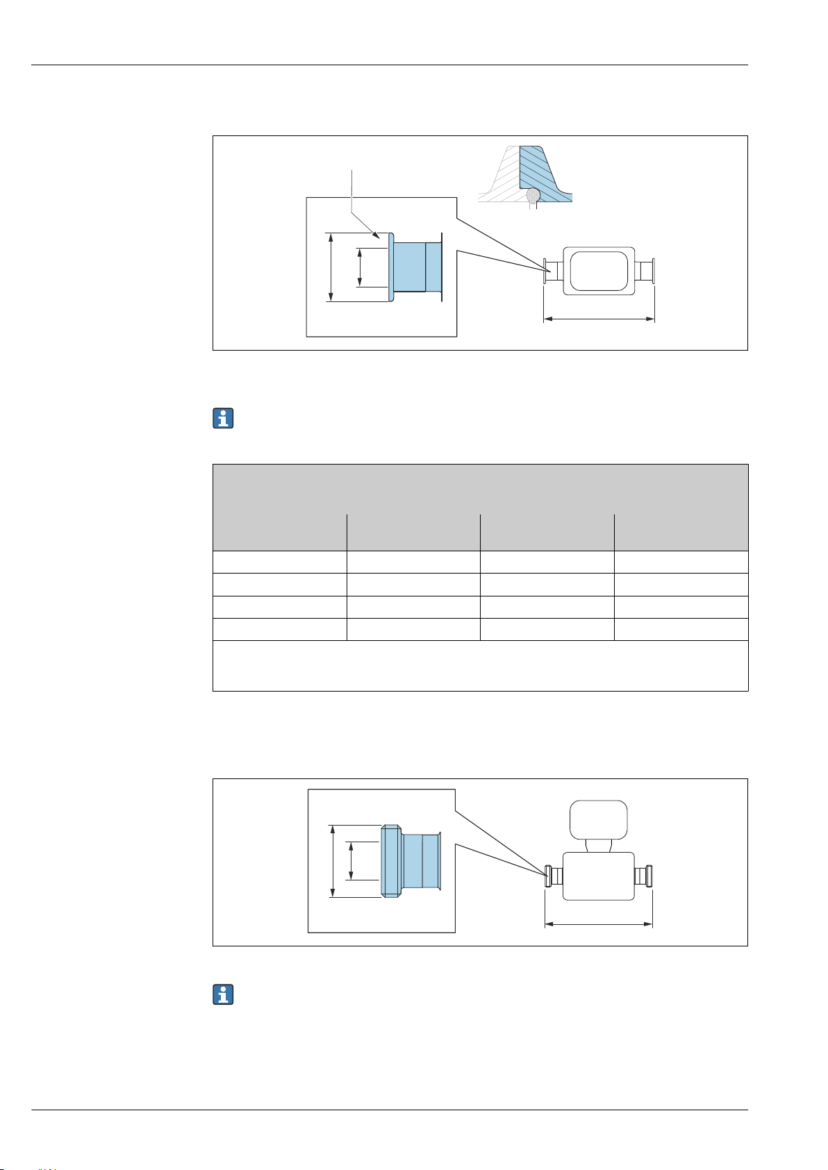
Proline Promass P 300
X
L
A
B
X
L
A
B
Neumo BioConnect eccentric clamp connection
43 Detail X: Asymmetrical process connection; the part shown in blue is provided by the supplier.
Length tolerance for dimension L in mm:
+1.5 / –2.0
A0016906
Neumo BioConnect eccentric clamp connection, for pipe according to DIN 11866 series C, clamp form R
1.4435 (316L)
Order code for "Process connection", option BEA
DN
[mm]
8 25 10.00 362
15 25 16.00 466
25 25 26.00 610
50 25 50.00 859
Ra
0.76 µm: order code for "Measuring tube material", option BB, TD
max
Ra
0.38 µm electropolished: order code for "Measuring tube material", option BC, TG
max
Additional information on "Eccentric clamps"
A
[mm]
B
[mm]
L
[mm]
Cable glands
Thread DIN 11851, DIN 11864-1, SMS 1145, BBS
Length tolerance for dimension L in mm:
+1.5 / –2.0
72 Endress+Hauser
A0015628
Page 73
Proline Promass P 300
Thread DIN 11851, for pipe according to DIN 11866 series A
1.4435 (316L)
Order code for "Process connection", option KCW
DN
[mm]
A
[mm]
B
[mm]
8 Rd 34 × ¹⁄₈ 16 362
15 Rd 34 × ¹⁄₈ 16 466
25 Rd 52 × ¹⁄₆ 26 606
40 Rd 65 × ¹⁄₆ 38 738
50 Rd 78 × ¹⁄₆ 50 864
Ra
0.76 µm: order code for "Measuring tube material", option BB, TD
max
Ra
0.38 µm electropolished: order code for "Measuring tube material", option BC, TG
max
Thread DIN 11851, Rd 28 × ¹⁄₈", for pipe according to DIN 11866 series A
1.4435 (316L)
Order code for "Process connection", option KAW
DN
[mm]
A
[mm]
B
[mm]
8 Rd 28 × ¹⁄₈" 10.00 362
15 Rd 28 × ¹⁄₈" 10.00 466
Ra
0.76 µm: order code for "Measuring tube material", option BB, TD
max
Ra
0.38 µm electropolished: order code for "Measuring tube material", option BC, TG
max
L
[mm]
L
[mm]
Thread DIN 11864-1 Form A, for pipe according to DIN 11866 series A
1.4435 (316L)
Order code for "Process connection", option KGW
DN
[mm]
A
[mm]
B
[mm]
8 Rd 34 × ¹⁄₈" 16 362
15 Rd 34 × ¹⁄₈" 16 466
25 Rd 52 × ¹⁄₆" 26 620
40 Rd 65 × ¹⁄₆" 38 738
50 Rd 78 × ¹⁄₆" 50 864
Ra
0.76 µm: order code for "Measuring tube material", option BB, TD
max
Ra
0.38 µm electropolished: order code for "Measuring tube material", option BC, TG
max
Threaded hygienic connection SMS 1145
1.4435 (316L)
Order code for "Process connection", option SAW
DN
[mm]
A
[mm]
B
[mm]
8 Rd 40 × ¹⁄₆" 22.50 362
15 Rd 40 × ¹⁄₆" 22.50 466
25 Rd 40 × ¹⁄₆" 22.50 606
40 Rd 60 × ¹⁄₆" 35.50 742
50 Rd 70 × ¹⁄₆" 48.50 864
Ra
0.76 µm: order code for "Measuring tube material", option BB, TD
max
Ra
0.38 µm electropolished: order code for "Measuring tube material", option BC, TG
max
L
[mm]
L
[mm]
Endress+Hauser 73
Page 74
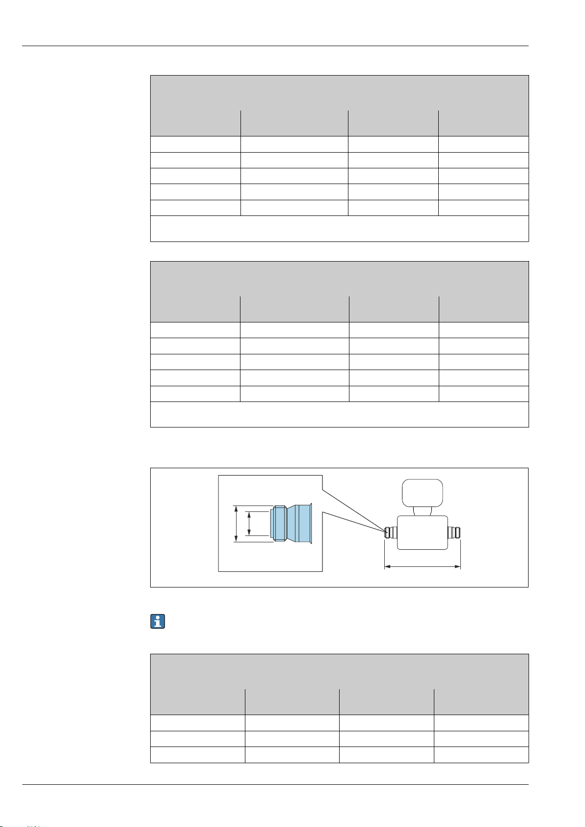
BBS thread (sterile orbital), for pipe according to DIN 11866 series A
L
A
B
1.4435 (316L)
Order code for "Process connection", option BSC
DN
[mm]
A
[mm]
B
[mm]
8 M22 ×1.5 10.00 362
15 M30 × 2 16.00 466
25 M42 × 2 26.00 606
40 M52 × 2 38.00 732
50 M68 × 2 50.00 854
Ra
0.76 µm: order code for "Measuring tube material", option BB, TD
max
Ra
0.38 µm electropolished: order code for "Measuring tube material", option BC, TG
max
BBS thread (sterile orbital), for pipe according to DIN 11866 series B
1.4435 (316L)
Order code for "Process connection", option BSD
DN
[mm]
A
[mm]
B
[mm]
8 M26 × 1.5 10.00 362
15 M30 × 2 16.00 466
25 M42 × 2 26.00 606
40 M56 × 2 38.00 738
50 M68 × 2 50.00 860
Ra
0.76 µm: order code for "Measuring tube material", option BB, TD
max
Ra
0.38 µm electropolished: order code for "Measuring tube material", option BC, TG
max
Proline Promass P 300
L
[mm]
L
[mm]
Threaded hygienic connection ISO 2853
Length tolerance for dimension L in mm:
+1.5 / –2.0
Threaded hygienic connection ISO 2853, for pipe according to ISO 2037
1.4435 (316L)
Order code for "Process connection", option JSD
DN
[mm]
8 37.13 22.60 370
15 37.13 22.60 474
25 37.13 22.60 614
A
[mm]
B
[mm]
A0015623
L
[mm]
74 Endress+Hauser
Page 75
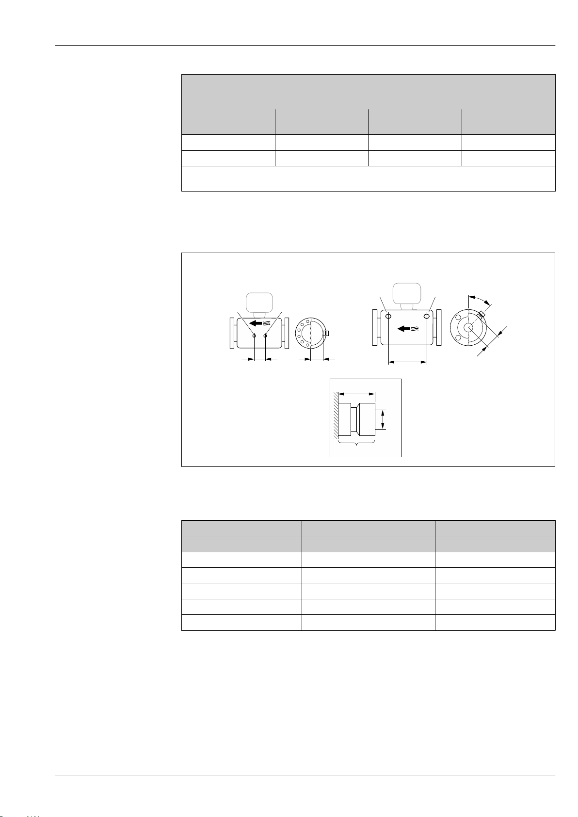
Proline Promass P 300
L
45°
A
1
½" NPT
35 (1.38)
1
1
L
A
1 1
DN 8 ( ")...25 (1")!⁄#
DN 40(1 ")…50 (2")
½
Threaded hygienic connection ISO 2853, for pipe according to ISO 2037
1.4435 (316L)
Order code for "Process connection", option JSD
DN
[mm]
40 50.65 35.60 742
50 64.10 48.60 864
Ra
0.76 µm: order code for "Measuring tube material", option BB, TD
max
Ra
0.38 µm electropolished: order code for "Measuring tube material", option BC, TG
max
A
[mm]
B
[mm]
Accessories
Rinse connections
L
[mm]
44
1 Connection nipple for purge connections: order code for "Sensor options", option CH "Purge connection"
A0029971
DN A L
[mm] [mm] [mm]
8 47 110
15 47 204
25 47 348
40 68.15 418
50 81.65 473
Endress+Hauser 75
Page 76
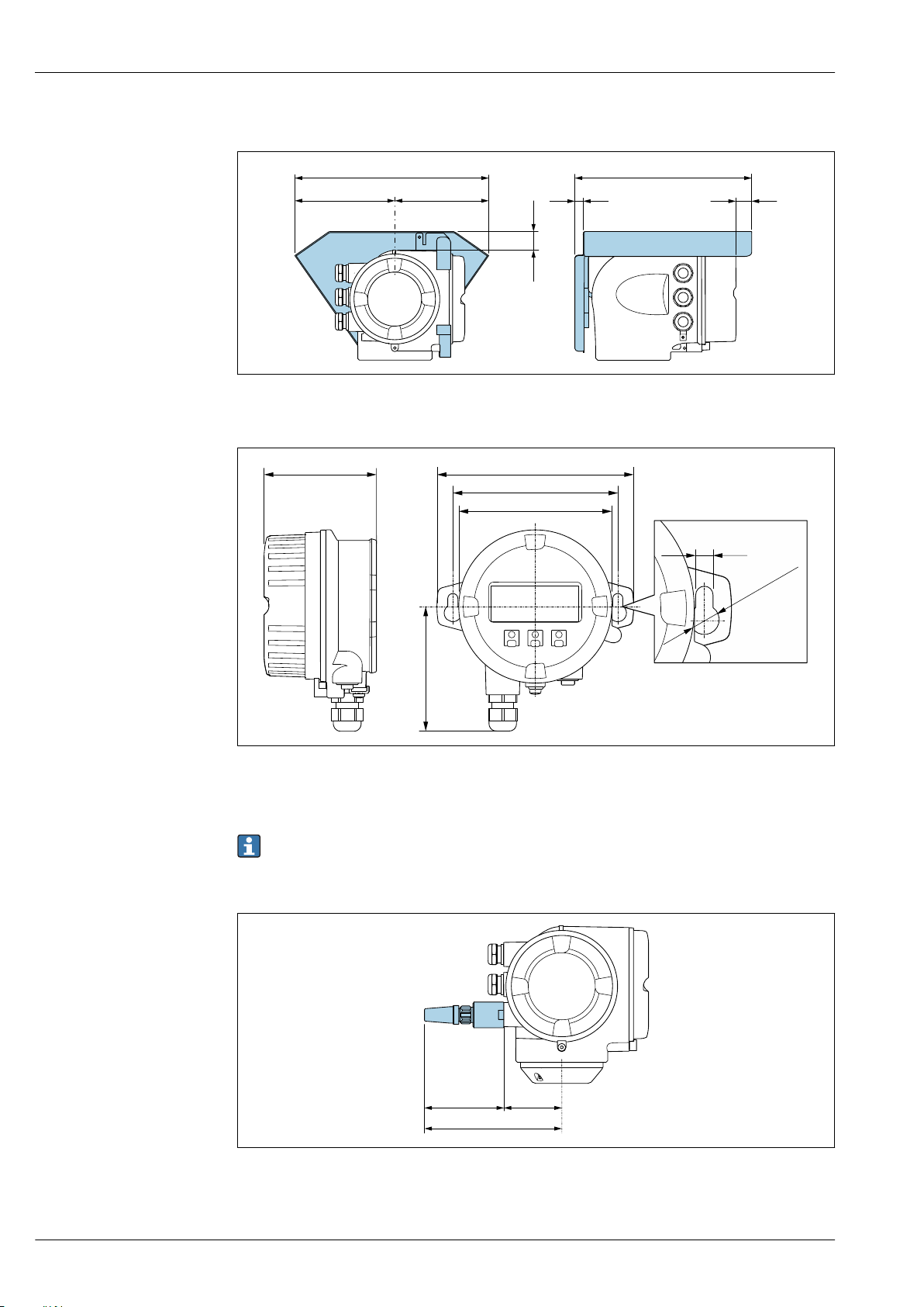
Protective cover
146 (5.75)
48 (1.9)
12 (0.47)
280 (11.0) 255 (10.0)
134 (5.3)
30 (1.18)
136 (5.35)
114 (4.49)
86 (3.39)
78 (3.07)
!103 (4.06)
!12 (0.47)
7.0 (0.27)
68 (2.7)105 (4.1)
173 (6.8)
Remote display and operating module DKX001
Proline Promass P 300
A0029553
45 Engineering unit mm (in)
External WLAN antenna
The external WLAN antenna is not suitable for use in hygienic applications.
External WLAN antenna mounted on device
46 Engineering unit mm (in)
A0028921
A0028923
76 Endress+Hauser
Page 77
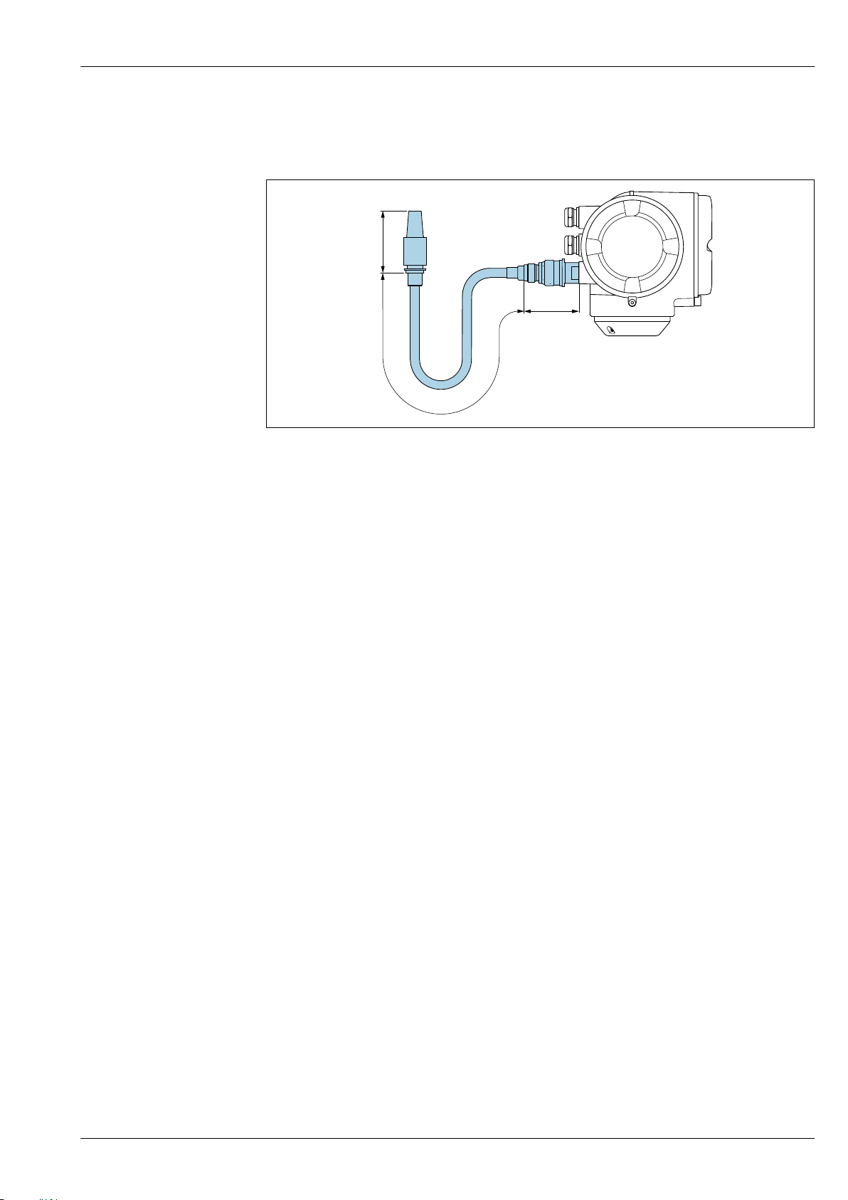
Proline Promass P 300
70 (2.8)
1500 (59.1)
72 (2.8)
External WLAN antenna mounted with cable
The external WLAN antenna can be mounted separately from the transmitter if the transmission/
reception conditions at the transmitter mounting location are poor.
A0033597
47 Engineering unit mm (in)
Endress+Hauser 77
Page 78
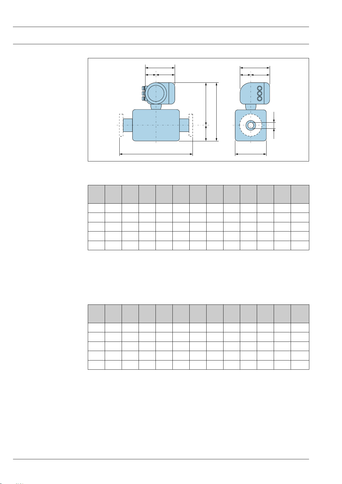
Dimensions in US units Compact version
D
L
E
F
A
CB
K
G
H
I
M
Order code for "Housing", option A "Aluminum, coated"
DN A
[in] [in] [in] [in] [in] [in] [in] [in] [in] [in] [in] [in] [in]
³⁄₈ 6.65 2.68 3.98 4.25 10.47 14.72 7.87 2.32 5.55 0.33
½ 6.65 2.68 3.98 4.25 10.47 14.72 7.87 2.32 5.55 0.47
1 6.65 2.68 3.98 4.76 10.47 15.24 7.87 2.32 5.55 0.69
1½ 6.65 2.68 3.98 6.93 11.69 18.7 7.87 2.32 5.55 1.02
2 6.65 2.68 3.98 10.24 12.2 22.52 7.87 2.32 5.55 1.49
1)
Proline Promass P 300
A0033783
1)
B
C D E
2)
2)
F
3)
G
H I
3)
K L M
4)
3.62
4)
3.62
4)
3.62
4)
5.59
4)
6.65
1) Depending on the cable gland used: values up to + 1.18 in
2) With order code for "Sensor option", option CG or order code for "Measuring tube material", option TD, TG:
values +2.76 in
3) For version without local display: values - 1.18 in
4) Depends on the process connection in question
Order code for "Housing", option A "Aluminum, coated"; Ex d
1)
DN A
1)
B
C D E
[in] [in] [in] [in] [in] [in] [in] [in] [in] [in] [in] [in] [in]
³⁄₈ 7.40 3.35 4.06 4.25 10.94 15.91 8.11 2.28 5.83 0.33
½ 7.40 3.35 4.06 4.25 10.94 15.91 8.11 2.28 5.83 0.47
1 7.40 3.35 4.06 4.76 10.94 16.42 8.11 2.28 5.83 0.69
1½ 7.40 3.35 4.06 6.93 12.13 19.88 8.11 2.28 5.83 1.02
2 7.40 3.35 4.06 10.24 12.68 23.7 8.11 2.28 5.83 1.49
1) Depending on the cable gland used: values up to + 1.18 in
2) With order code for "Sensor option", option CG or order code for "Measuring tube material", option TD, TG:
values +2.76 in
3) For version without local display: values - 1.49 in
4) Depends on the process connection in question
2)
2)
F
3)
G
H I
3)
K L M
4)
3.62
4)
3.62
4)
3.62
4)
5.59
4)
6.65
78 Endress+Hauser
Page 79
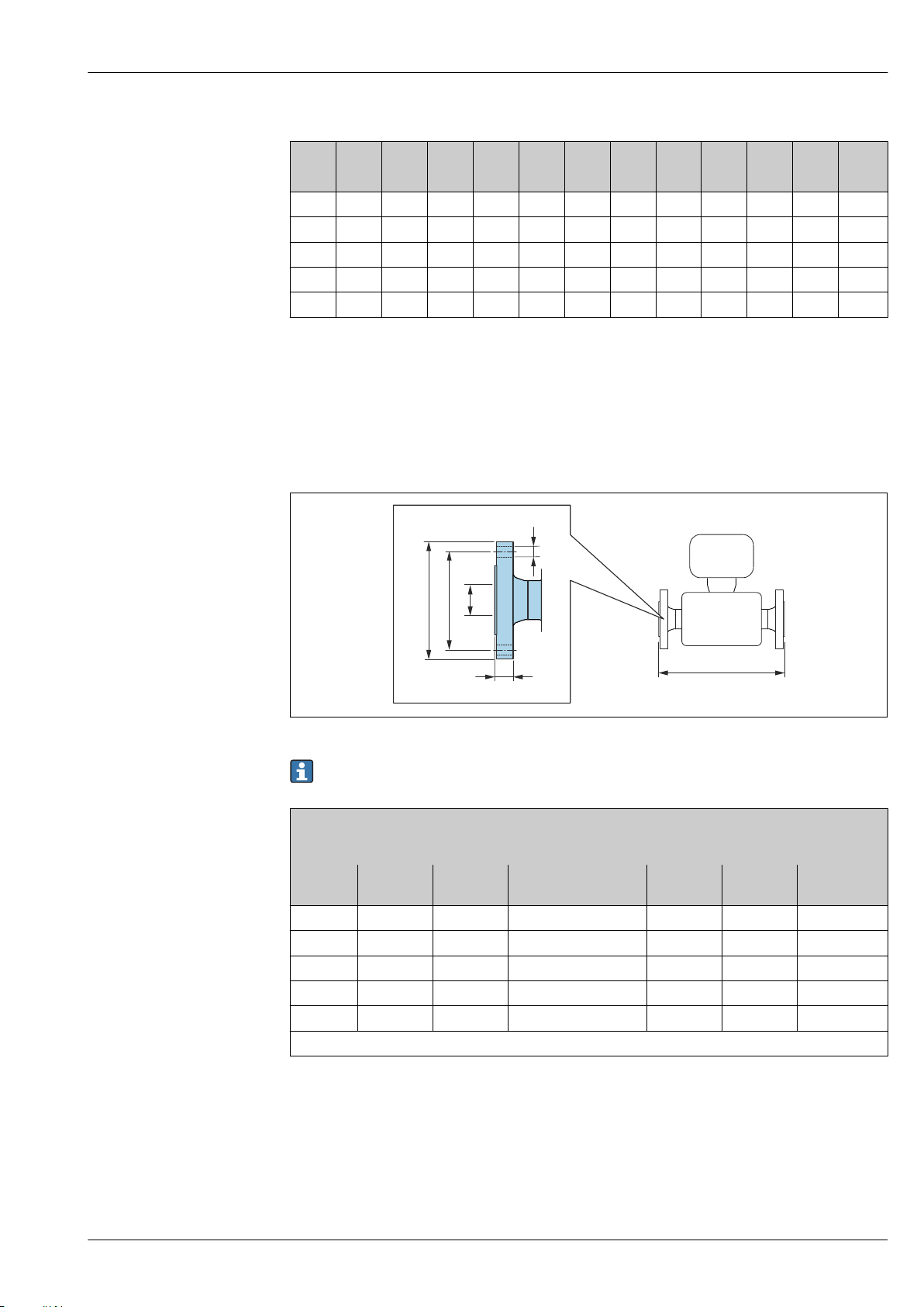
Proline Promass P 300
C
D
A
B
E
L
Order code for "Housing", option B "Stainless, hygienic"
DN A
1)
B
C D E
2)
2)
F
G H I K L M
1)
[in] [in] [in] [in] [in] [in] [in] [in] [in] [in] [in] [in] [in]
³⁄₈ 7.20 2.87 4.33 4.25 10.47 14.72 8.15 2.56 5.59 0.33
½ 7.20 2.87 4.33 4.25 10.47 14.72 8.15 2.56 5.59 0.47
1 7.20 2.87 4.33 4.76 10.47 15.24 8.15 2.56 5.59 0.69
1½ 7.20 2.87 4.33 6.93 11.69 18.70 8.15 2.56 5.59 1.02
2 7.20 2.87 4.33 10.24 12.20 22.52 8.15 2.56 5.59 1.49
3)
3.62
3)
3.62
3)
3.62
3)
5.59
3)
6.65
1) Depending on the cable gland used: values up to + 1.18 in
2) With order code for "Sensor option", option CG or order code for "Measuring tube material", option TD, TG:
values +2.76 in
3) Depends on the process connection in question
Flange connections
Fixed flange ASME B16.5
A0015621
Length tolerance for dimension L in inch:
+0.06 / –0.08
Flange according to ASME B16.5: Cl 150
1.4404 (316/316L)
Order code for "Process connection", option AAW
DN
[in]
³⁄₈
1)
A
[in]
B
[in]
C
[in]
D
[in]
[in]
E
L
[in]
3.54 2.37 4 × Ø0.62 0.44 0.62 13.23
½ 3.54 2.37 4 × Ø0.62 0.44 0.62 17.32
1 4.33 3.13 4 × Ø0.62 0.56 1.05 22.83
1½ 4.92 3.87 4 × Ø0.62 0.69 1.61 27.83
2 5.91 4.75 4 × Ø0.75 0.75 2.07 32.6
Surface roughness (flange): Ra 3.2 to 6.3 µm
1) DN ³⁄₈" with DN ½" flanges as standard
Endress+Hauser 79
Page 80
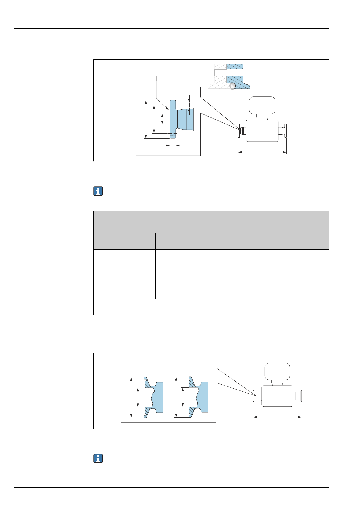
Proline Promass P 300
L
C
D
A
B
E
XX
L
A
B
≥ (1")DN 25DN 8, 15 (¾", ½")
A
B
Neumo BioConnect fixed flange
48 Detail X: Asymmetrical process connection; the part shown in blue is provided by the supplier.
Length tolerance for dimension L in inch:
+0.06 / –0.08
A0016907
Neumo BioConnect flange (sterile orbital), for pipe according to DIN 11866 series A, flange form R
1.4435 (316L)
Order code for "Process connection", option BSB
DN
[in]
³⁄₈ 2.56 1.77 4 × ⌀0.35 0.39 0.39 15.12
½ 2.95 2.17 4 × ⌀0.35 0.39 0.63 19.21
1 3.35 2.56 4 × ⌀0.35 0.47 1.02 24.65
1½ 3.94 3.15 4 × ⌀0.35 0.47 1.5 29.65
2 4.33 3.54 4 × ⌀0.35 0.55 1.97 34.53
Ra
30 µin: order code for "Measuring tube material", option BB, TD
max
Ra
15 µin electropolished: order code for "Measuring tube material", option BC, TG
max
A
[in]
B
[in]
C
[in]
D
[in]
E
[in]
Clamp connections
Tri-Clamp
L
[in]
49 Engineering unit mm (in)
Length tolerance for dimension L in inch:
+0.06 / –0.08
80 Endress+Hauser
A0023342
Page 81
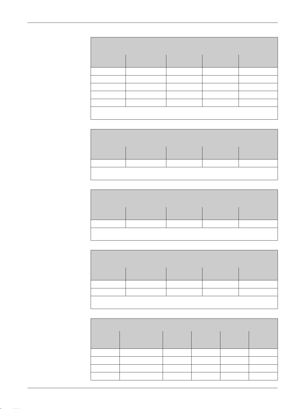
Proline Promass P 300
Tri-Clamp; for pipe according to DIN 11866 series C
1.4435 (316L)
Order code for "Process connection", option FHW
DN
[in]
Clamp
[in]
A
[in]
B
[in]
³⁄₈ ½ 0.98 0.37 14.25
½ ¾ 0.98 0.62 18.35
1 1 1.98 0.87 23.86
1½ 1 ½ 1.98 1.37 28.78
2 2 2.52 1.87 33.58
Ra
30 µin: order code for "Measuring tube material", option BB, TD
max
Ra
15 µin electropolished: order code for "Measuring tube material", option BC, TG
max
½" Tri-Clamp; for pipe according to DIN 11866 series C
1.4435 (316L)
Order code for "Process connection", option FCW
DN
[in]
Clamp
[in]
A
[in]
B
[in]
½ ½ 0.98 0.37 18.35
Ra
30 µin: order code for "Measuring tube material", option BB, TD
max
Ra
15 µin electropolished: order code for "Measuring tube material", option BC, TG
max
L
[in]
L
[in]
¾" Tri-Clamp; for pipe according to DIN 11866 series C
1.4435 (316L)
Order code for "Process connection", option FFW
DN
[in]
Clamp
[in]
A
[in]
B
[in]
³⁄₈ ¾ 0.98 0.62 14.25
Ra
30 µin: order code for "Measuring tube material", option BB, TD
max
Ra
15 µin electropolished: order code for "Measuring tube material", option BC, TG
max
1" Tri-Clamp; for pipe according to DIN 11866 series C
1.4435 (316L)
Order code for "Process connection", option FPW
DN
[in]
Clamp
[in]
A
[in]
B
[in]
³⁄₈ 1 1.98 0.87 14.25
½ 1 1.98 0.87 18.35
Ra
30 µin: order code for "Measuring tube material", option BB, TD
max
Ra
15 µin electropolished: order code for "Measuring tube material", option BC, TG
max
Tri-Clamp eccentric; for pipe according to DIN 11866 series C
1.4435 (316L)
DN
[in]
Order code for
"Process connection",
Clamp
[in]
A
[in]
B
[in]
option
³⁄₈ FEB ½ 0.98 0.37 14.25
½ FED ¾ 0.98 0.62 18.35
1 FEF 1 1.98 0.87 23.86
1½ FEH 1½ 1.98 1.37 29.06
L
[in]
L
[in]
L
[in]
Endress+Hauser 81
Page 82
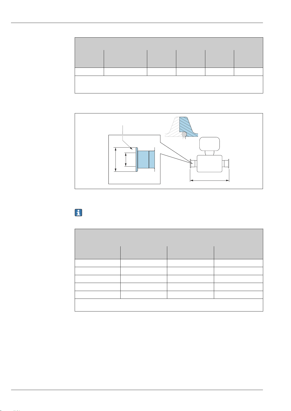
Proline Promass P 300
L
X
A
B
X
Tri-Clamp eccentric; for pipe according to DIN 11866 series C
1.4435 (316L)
DN
[in]
2 FEK 2 2.52 1.87 33.86
Ra
30 µin: order code for "Measuring tube material", option BB, TD
max
Ra
15 µin electropolished: order code for "Measuring tube material", option BC, TG
max
Additional information on "Eccentric clamps"
Neumo BioConnect clamp connection
Order code for
"Process connection",
option
Clamp
[in]
A
[in]
B
[in]
L
[in]
50 Detail X: Asymmetrical process connection; the part shown in blue is provided by the supplier.
Length tolerance for dimension L in inch:
+0.06 / –0.08
Clamp; Neumo BioConnect (sterile orbital), for pipe according to DIN 11866 series A, clamp form R
1.4435 (316L)
Order code for "Process connection", option BSA
DN
[in]
³⁄₈ 0.98 0.39 14.25
½ 0.98 0.63 18.35
1 1.98 1.02 23.86
1½ 2.52 1.5 28.82
2 3.05 1.97 33.62
Ra
30 µin: order code for "Measuring tube material", option BB, TD
max
Ra
15 µin electropolished: order code for "Measuring tube material", option BC, TG
max
A
[in]
B
[in]
L
[in]
A0016905
82 Endress+Hauser
Page 83
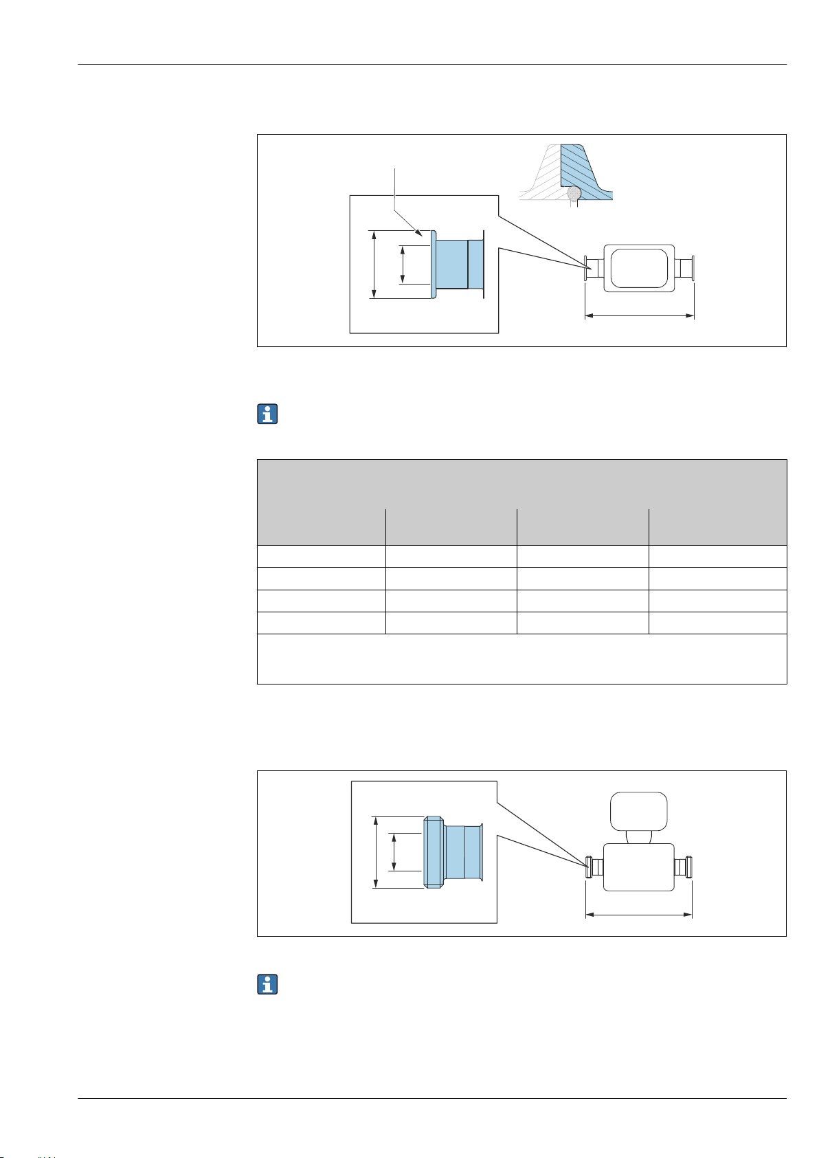
Proline Promass P 300
X
L
A
B
X
L
A
B
Neumo BioConnect eccentric clamp connection
A0016906
51 Detail X: Asymmetrical process connection; the part shown in blue is provided by the supplier.
Length tolerance for dimension L in inch:
+0.06 / –0.08
Neumo BioConnect eccentric clamp connection, for pipe according to DIN 11866 series C, clamp form R
1.4435 (316L)
Order code for "Process connection", option BEA
DN
[in]
³⁄₈ 0.98 0.39 14.25
½ 0.98 0.63 18.35
1 0.98 1.02 24.02
2 0.98 1.97 43.39
Ra
30 µin: order code for "Measuring tube material", option BB, TD
max
Ra
15 µin electropolished: order code for "Measuring tube material", option BC, TG
max
Additional information on "Eccentric clamps"
A
[in]
B
[in]
L
[in]
Cable glands
Threaded hygienic connection SMS 1145
A0015628
Length tolerance for dimension L in inch:
+0.06 / –0.08
Endress+Hauser 83
Page 84
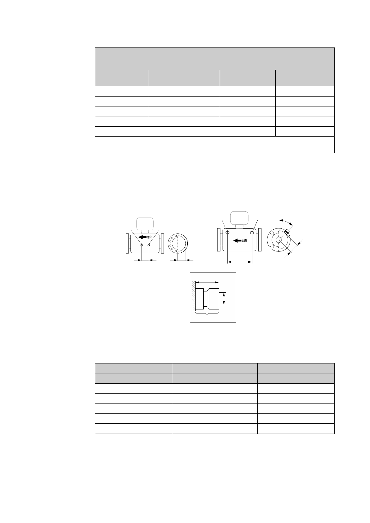
Threaded hygienic connection SMS 1145
L
45°
A
1
½" NPT
35 (1.38)
1
1
L
A
1 1
DN 8 ( ")...25 (1")!⁄#
DN 40(1 ")…50 (2")
½
1.4435 (316L)
Order code for "Process connection", option SAW
DN
[in]
³⁄₈ Rd 40 × ¹⁄₆ 0.89 14.25
½ Rd 40 × ¹⁄₆ 0.89 18.35
1 Rd 40 × ¹⁄₆ 0.89 23.86
1½ Rd 60 × ¹⁄₆ 1.4 29.21
2 Rd 70 × ¹⁄₆ 1.91 34.02
Ra
30 µin: order code for "Measuring tube material", option BB, TD
max
Ra
15 µin electropolished: order code for "Measuring tube material", option BC, TG
max
A
[in]
Accessories
Rinse connections
B
[in]
Proline Promass P 300
L
[in]
52
1 Connection nipple for purge connections: order code for "Sensor options", option CH "Purge connection"
DN A L
[in] [in] [in]
³⁄₈ 1.85 4.33
½ 1.85 8.03
1 1.85 13.7
1½ 2.683 16.46
2 3.215 18.62
84 Endress+Hauser
A0029971
Page 85
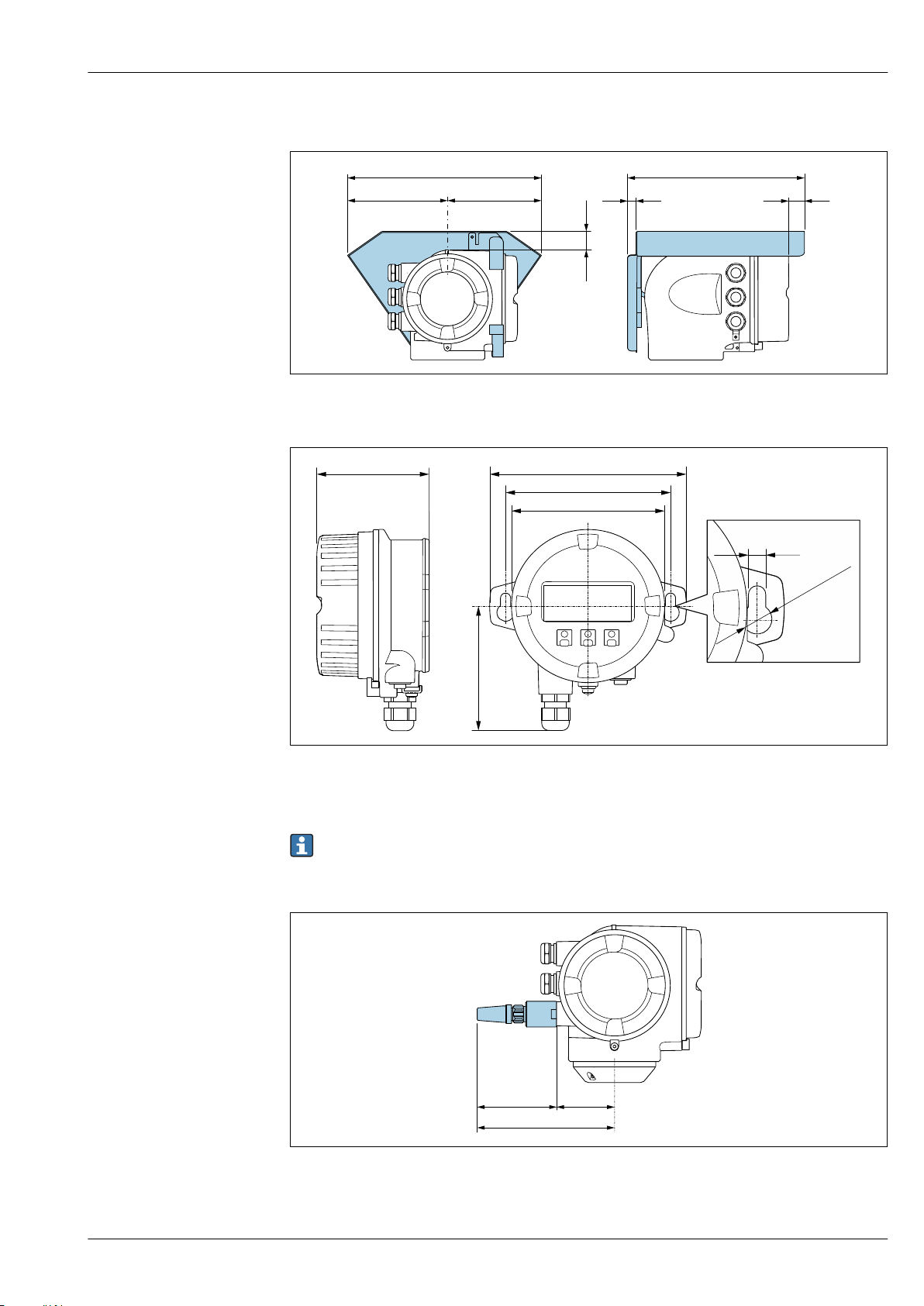
Proline Promass P 300
146 (5.75)
48 (1.9)
12 (0.47)
280 (11.0) 255 (10.0)
134 (5.3)
30 (1.18)
136 (5.35)
114 (4.49)
86 (3.39)
78 (3.07)
!103 (4.06)
!12 (0.47)
7.0 (0.27)
68 (2.7)105 (4.1)
173 (6.8)
Protective cover
A0029553
Remote display and operating module DKX001
53 Engineering unit mm (in)
External WLAN antenna
External WLAN antenna mounted on device
54 Engineering unit mm (in)
A0028921
The external WLAN antenna is not suitable for use in hygienic applications.
A0028923
Endress+Hauser 85
Page 86
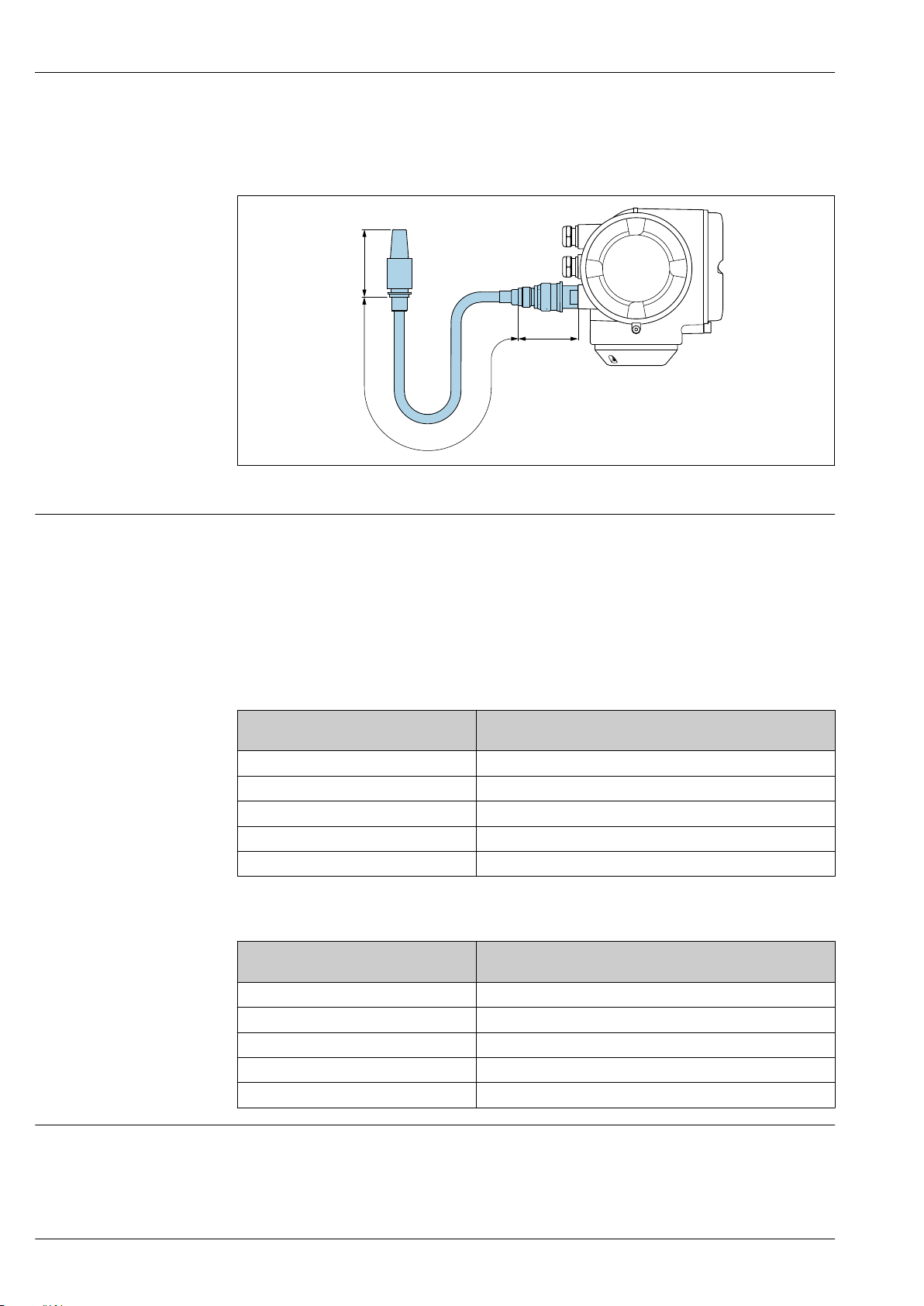
Proline Promass P 300
70 (2.8)
1500 (59.1)
72 (2.8)
External WLAN antenna mounted with cable
The external WLAN antenna can be mounted separately from the transmitter if the transmission/
reception conditions at the transmitter mounting location are poor.
A0033597
55 Engineering unit mm (in)
Weight
All values (weight exclusive of packaging material) refer to devices with EN/DIN PN 40 flanges.
Weight specifications including transmitter as per order code for "Housing", option A "Aluminum,
coated".
Different values due to different transmitter versions:
• Transmitter version for the hazardous area
(Order code for "Housing", option A "Aluminum, coated"; Ex d): +2 kg (+4.4 lbs)
• Transmitter version for hygienic area
(Order code for "Housing", option B "Stainless, hygienic"): +0.2 kg (+0.44 lbs)
Weight in SI units
DN
[mm]
8 12
15 14
25 20
40 36
50 59
Weight [kg]
Weight in US units
DN
[in]
3/8 26
½ 31
1 44
1½ 79
2 130
Weight [lbs]
Materials Transmitter housing
Order code for "Housing":
• Option A "Aluminum, coated": aluminum, AlSi10Mg, coated
• Option B "Stainless, hygienic": stainless steel, 1.4404 (316L)
86 Endress+Hauser
Page 87
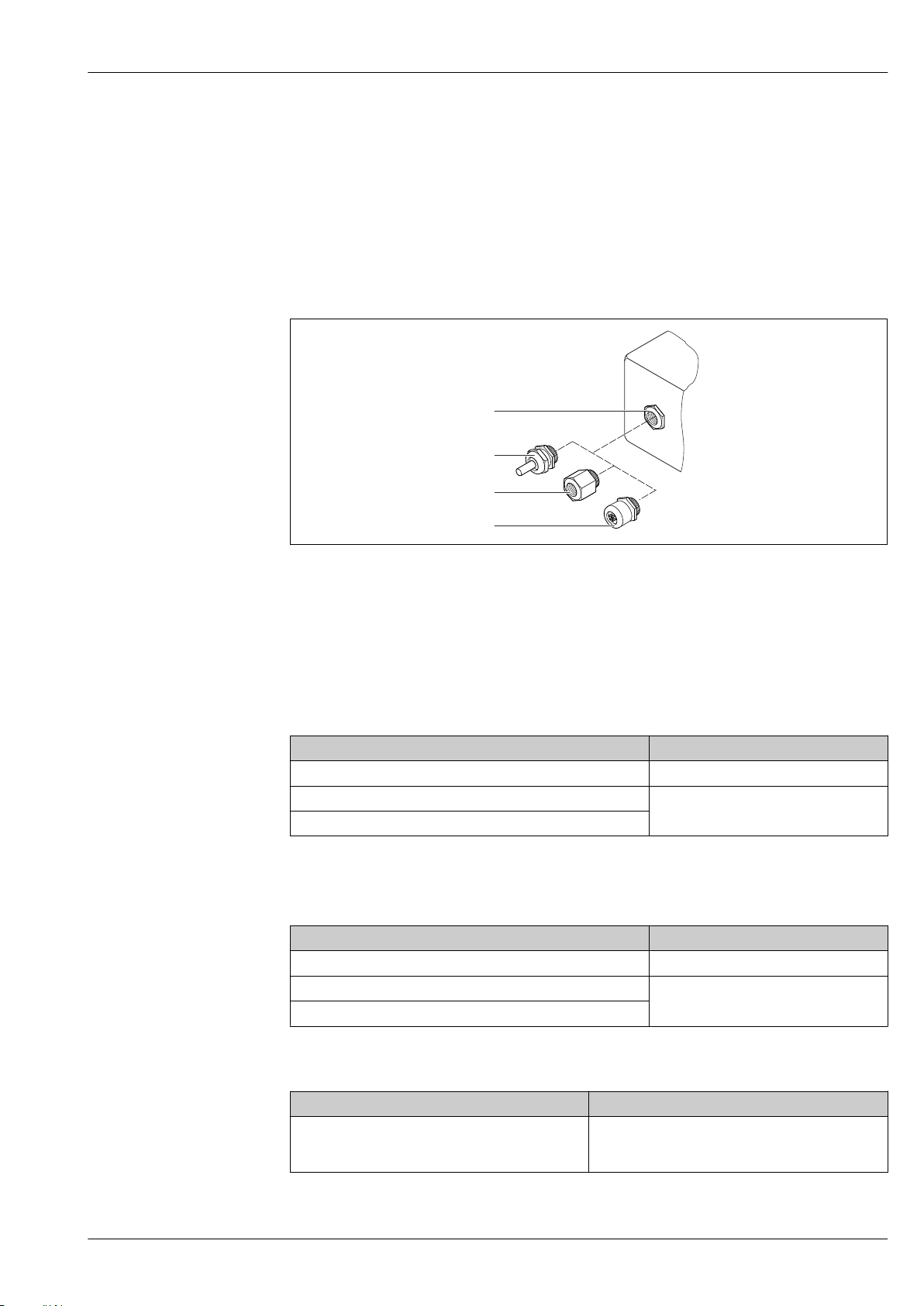
Proline Promass P 300
1
2
3
4
Window material
Order code for "Housing":
• Option A "Aluminum, coated": glass
• Option B "Stainless, hygienic": polycarbonate
Seals
Order code for "Housing":
Option B "Stainless, hygienic": EPDM and silicone
Cable entries/cable glands
56 Possible cable entries/cable glands
1 Female thread M20 × 1.5
2 Cable gland M20 × 1.5
3 Adapter for cable entry with internal thread G ½" or NPT ½"
4 Device plugs
Order code for "Housing", option A "Aluminum, coated"
The various cable entries are suitable for hazardous and non-hazardous areas.
Cable entry/cable gland Material
Cable gland M20 × 1.5 Plastic/nickel-plated brass
Adapter for cable entry with internal thread G ½" Nickel-plated brass
Adapter for cable entry with internal thread NPT ½"
Order code for "Housing", option B "Stainless, hygienic"
The various cable entries are suitable for hazardous and non-hazardous areas.
Cable entry/cable gland Material
Cable gland M20 × 1.5 Plastic
Adapter for cable entry with internal thread G ½" Nickel-plated brass
Adapter for cable entry with internal thread NPT ½"
A0028352
Device plug
Electrical connection Material
Plug M12x1 • Socket: Stainless steel, 1.4404 (316L)
• Contact housing: Polyamide
• Contacts: Gold-plated brass
Endress+Hauser 87
Page 88

Proline Promass P 300
Sensor housing
• Acid and alkali-resistant outer surface
• Stainless steel 1.4301 (304)
Measuring tubes
Stainless steel, 1.4435 BN2 (316L)
Process connections
• Flanges according to EN 1092-1 (DIN 2501) / according to ASME B16.5 / according to JIS B2220:
Stainless steel, 1.4404 (316/316L)
• All other process connections:
Stainless steel, 1.4435 BN2 (316L)
Available process connections→ 89
Seals
Welded process connections without internal seals
Accessories
Protective cover
Stainless steel, 1.4404 (316L)
External WLAN antenna
• Antenna: ASA plastic (acrylic ester-styrene-acrylonitrile) and nickel-plated brass
• Adapter: Stainless steel and nickel-plated brass
• Cable: Polyethylene
• Plug: Nickel-plated brass
• Angle bracket: Stainless steel
88 Endress+Hauser
Page 89
Proline Promass P 300
Process connections
• Fixed flange connections:
– EN 1092-1 (DIN 2501) flange
– EN 1092-1 (DIN 2512N) flange
– ASME B16.5 flange
– JIS B2220 flange
– DIN 11864-2 Form A flange, DIN 11866 series A, flange with notch
– BBS flange small (sterile orbital), DIN 11866 series A, female
– BBS flange small (sterile orbital), DIN 11866 series B, female
• Clamp connections:
– Tri-Clamp (OD tubes), DIN 11866 series C
– DIN 11864-3 Form A clamp, DIN 11866 series A, with notch
– DIN 32676 clamp, DIN 11866 series A
– ISO 2852 clamp, ISO 2037
– ISO 2852 clamp, DIN 11866 series B
– BBS Quick-Connect (sterile orbital), DIN 11866 series A, female
– BBS Quick-Connect (sterile orbital), DIN 11866 series B, female
– Neumo BioConnect clamp, DIN 11866 series A, clamp form R
• Eccentric clamp connection:
– Eccen. Tri-Clamp, DIN 11866 series C
– DIN 11864-3 Form A clamp, DIN 11866 series A, with notch
– DIN 32676 clamp, DIN 11866 series A
– ISO 2852 clamp, DIN 11866 series B
– BBS Quick-Connect (sterile orbital), DIN 11866 series A, female
– BBS Quick-Connect (sterile orbital), DIN 11866 series B, female
– Neumo BioConnect clamp, DIN 11866 series A, clamp form R
• Thread:
– DIN 11851 thread, DIN 11866 series A
– SMS 1145 thread
– ISO 2853 thread, ISO 2037
– DIN 11864-1 Form A thread, DIN 11866 series A
– BBS thread (sterile orbital), DIN 11866 series A
– BBS thread (sterile orbital), DIN 11866 series B
Process connection materials → 88
Surface roughness
Operating concept
All data relate to parts in contact with fluid. The following surface roughness quality can be ordered.
• Ra
= 0.76 µm (30 µin)
max
• Ra
= 0.38 µm (15 µin) electropolished
max
• Delta ferrite <1%
Operability
Operator-oriented menu structure for user-specific tasks
• Commissioning
• Operation
• Diagnostics
• Expert level
Fast and safe commissioning
• Guided menus ("Make-it-run" wizards) for applications
• Menu guidance with brief descriptions of the individual parameter functions
• Device access via Web server or SmartBlue app → 109
• WLAN access to the device via mobile handheld terminal, tablet or smart phone
Reliable operation
• Operation in local language → 90
• Uniform operating philosophy applied to device and operating tools
• If replacing electronic modules, transfer the device configuration via the integrated memory
(HistoROM backup) which contains the process and measuring device data and the event logbook.
No need to reconfigure.
Endress+Hauser 89
Page 90
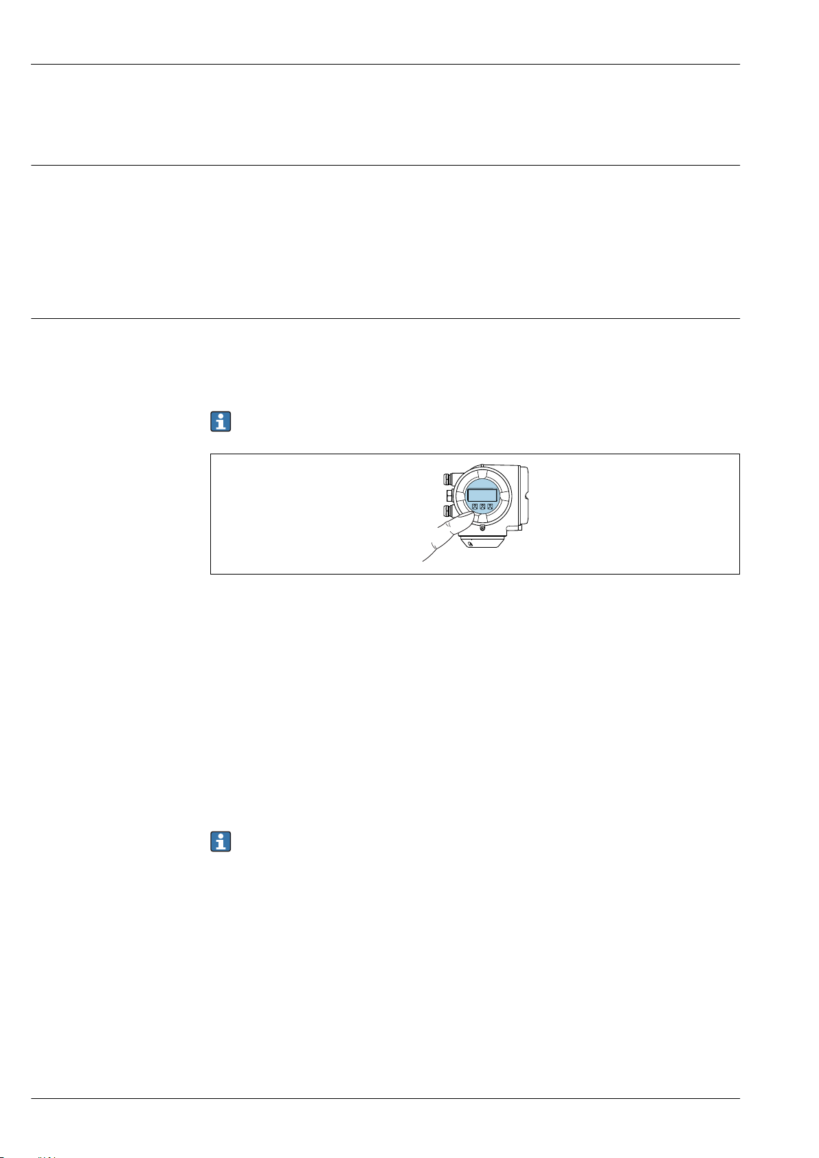
Proline Promass P 300
Efficient diagnostics increase measurement availability
• Troubleshooting measures can be called up via the device and in the operating tools
• Diverse simulation options, logbook for events that occur and optional line recorder functions
Languages
Can be operated in the following languages:
• Via local operation
English, German, French, Spanish, Italian, Dutch, Portuguese, Polish, Russian, Turkish, Chinese,
Japanese, Korean, Bahasa (Indonesian), Vietnamese, Czech, Swedish
• Via Web browser
English, German, French, Spanish, Italian, Dutch, Portuguese, Polish, Russian, Turkish, Chinese,
Japanese, Korean, Bahasa (Indonesian), Vietnamese, Czech, Swedish
• Via "FieldCare", "DeviceCare" operating tool: English, German, French, Spanish, Italian, Chinese,
Japanese
Local operation Via display module
Two display modules are available:
• Order code for "Display; operation", option F "4-line, illuminated, graphic display; touch control"
• Order code for "Display; operation", option G "4-line, illuminated, graphic display; touch control +
WLAN"
Information about WLAN interface → 97
57 Operation with touch control
Display elements
• 4-line, illuminated, graphic display
• White background lighting; switches to red in event of device errors
• Format for displaying measured variables and status variables can be individually configured
• Permitted ambient temperature for the display: –20 to +60 °C (–4 to +140 °F)
The readability of the display may be impaired at temperatures outside the temperature range.
Operating elements
• External operation via touch control (3 optical keys) without opening the housing: , ,
• Operating elements also accessible in the various zones of the hazardous area
Via remote display and operating module DKX001
The remote display and operating module DKX001 is available as an optional extra → 107.
• The remote display and operating module DKX001 is only available for the following housing
version: order code for "Housing": option A "Aluminum, coated"
• The measuring device is always supplied with a dummy cover when the remote display and
operating module DKX001 is ordered directly with the measuring device. Display or operation
at the transmitter is not possible in this case.
• If ordered subsequently, the remote display and operating module DKX001 may not be
connected at the same time as the existing measuring device display module. Only one
display or operation unit may be connected to the transmitter at any one time.
A0026785
90 Endress+Hauser
Page 91
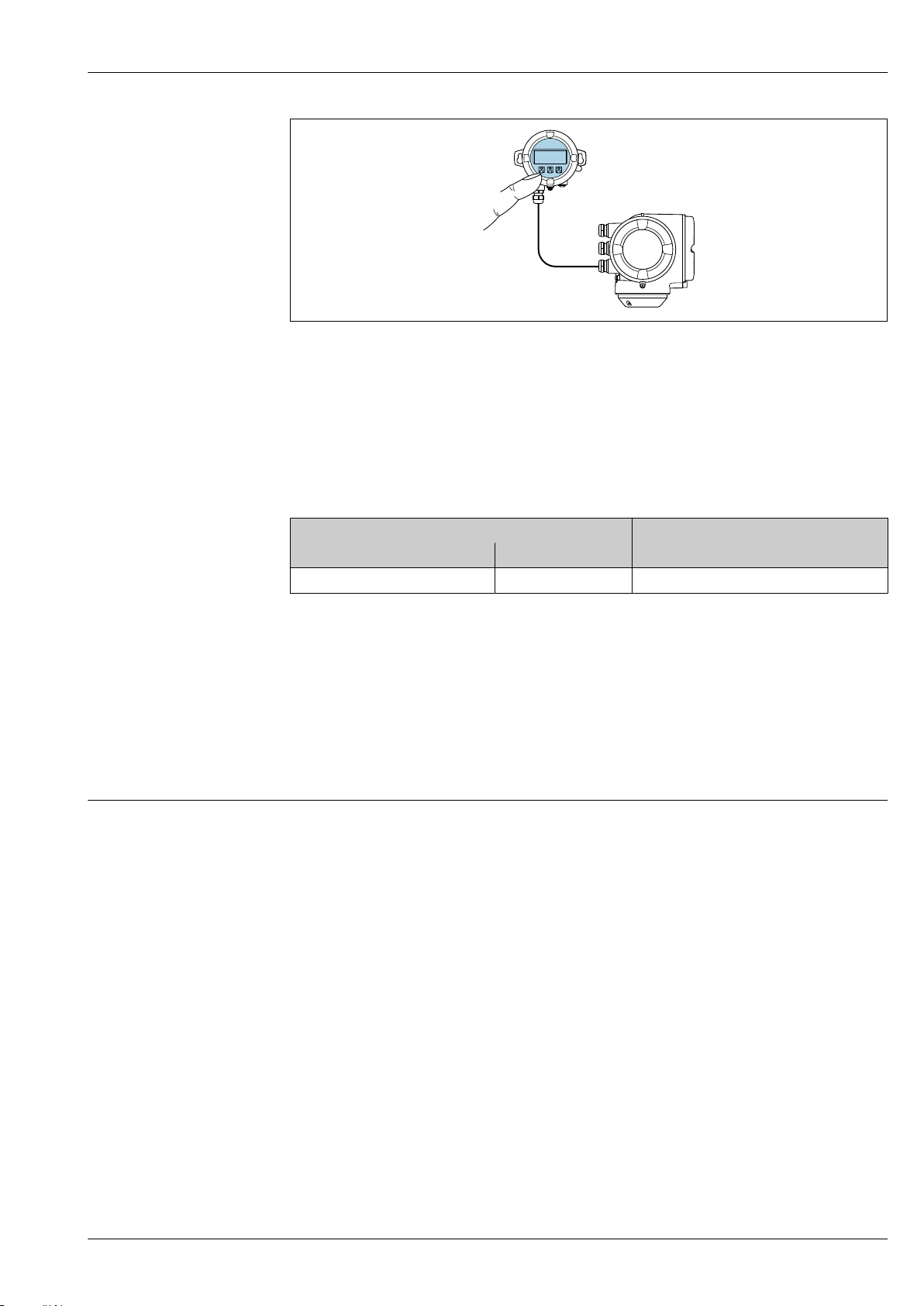
Proline Promass P 300
A0026786
58 Operation via remote display and operating module DKX001
Display and operating elements
The display and operating elements correspond to those of the display module → 90.
Material
The housing material of the display and operating module DKX001 depends on the choice of
transmitter housing material.
Transmitter housing Remote display and operating module
Order code for "Housing" Material Material
Option A "Aluminum, coated" AlSi10Mg, coated AlSi10Mg, coated
Cable entry
Corresponds to the choice of transmitter housing, order code for "Electrical connection".
Connecting cable
→ 41
Dimensions
→ 76
Remote operation Via HART protocol
This communication interface is available in device versions with a HART output.
Endress+Hauser 91
Page 92
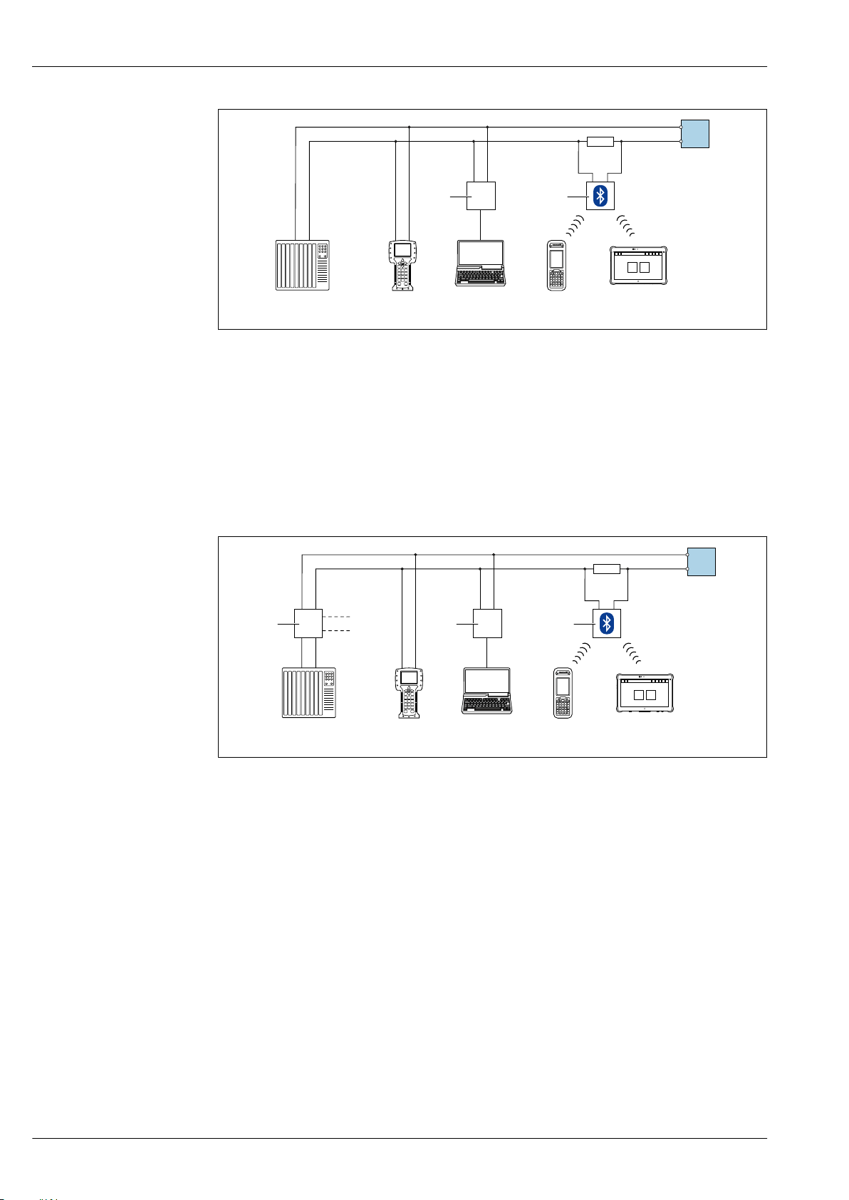
Proline Promass P 300
1 2 3 5
8
4 7
6
1
10
2
3
4 5 7
6 9
8
59 Options for remote operation via HART protocol (active)
1 Control system (e.g. PLC)
2 Field Communicator 475
3 Computer with Web browser (e.g. Internet Explorer) for access to the integrated device Web server or
computer with an operating tool (e.g. FieldCare, DeviceCare, AMS Device Manager, SIMATIC PDM) with COM
DTM "CDI Communication TCP/IP"
4 Commubox FXA195 (USB)
5 Field Xpert SFX350 or SFX370
6 Field Xpert SMT70
7 VIATOR Bluetooth modem with connecting cable
8 Transmitter
A0028747
60 Options for remote operation via HART protocol (passive)
1 Control system (e.g. PLC)
2 Transmitter power supply unit, e.g. RN221N (with communication resistor)
3 Connection for Commubox FXA195 and Field Communicator 475
4 Field Communicator 475
5 Computer with Web browser (e.g. Internet Explorer) for access to the integrated device Web server or
computer with an operating tool (e.g. FieldCare, DeviceCare, AMS Device Manager, SIMATIC PDM) with COM
DTM "CDI Communication TCP/IP"
6 Commubox FXA195 (USB)
7 Field Xpert SFX350 or SFX370
8 Field Xpert SMT70
9 VIATOR Bluetooth modem with connecting cable
10 Transmitter
Via FOUNDATION Fieldbus network
This communication interface is available in device versions with FOUNDATION Fieldbus.
92 Endress+Hauser
A0028746
Page 93
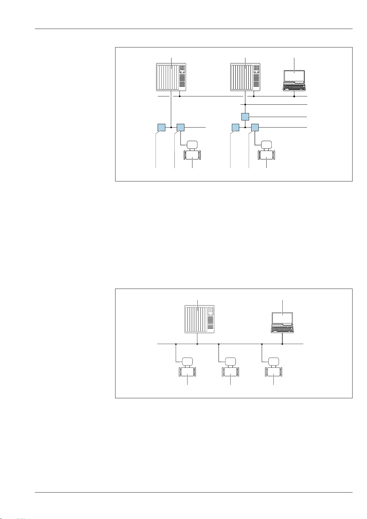
Proline Promass P 300
1 2
3
1
98 98
4
6 6
5
1 2
3
444
A0028837
61 Options for remote operation via FOUNDATION Fieldbus network
1 Automation system
2 Computer with FOUNDATION Fieldbus network card
3 Industry network
4 High Speed Ethernet FF-HSE network
5 Segment coupler FF-HSE/FF-H1
6 FOUNDATION Fieldbus FF-H1 network
7 Power supply FF-H1 network
8 T-box
9 Measuring device
Via PROFIBUS DP network
This communication interface is available in device versions with PROFIBUS DP.
62 Options for remote operation via PROFIBUS DP network
1 Automation system
2 Computer with PROFIBUS network card
3 PROFIBUS DP network
4 Measuring device
Via PROFIBUS PA network
This communication interface is available in device versions with PROFIBUS PA.
A0020903
Endress+Hauser 93
Page 94
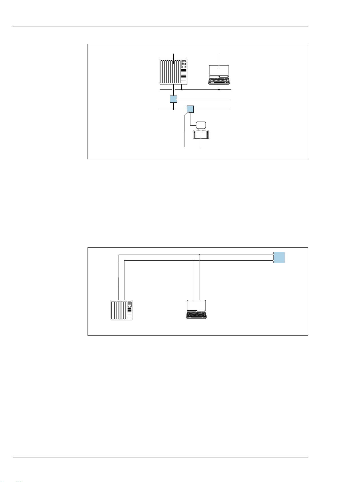
2
3
1
76
5
4
63 Options for remote operation via PROFIBUS PA network
1 2
3
1 Automation system
2 Computer with PROFIBUS network card
3 PROFIBUS DP network
4 Segment coupler PROFIBUS DP/PA
5 PROFIBUS PA network
6 T-box
7 Measuring device
Proline Promass P 300
A0028838
Via Modbus RS485 protocol
This communication interface is available in device versions with a Modbus-RS485 output.
A0029437
64 Options for remote operation via Modbus-RS485 protocol (active)
1 Control system (e.g. PLC)
2 Computer with Web browser (e.g. Internet Explorer) for accessing the integrated device Web server or with
operating tool (e.g. FieldCare, DeviceCare) with COM DTM "CDI Communication TCP/IP" or Modbus DTM
3 Transmitter
Via EtherNet/IP network
This communication interface is available in device versions with EtherNet/IP.
94 Endress+Hauser
Page 95
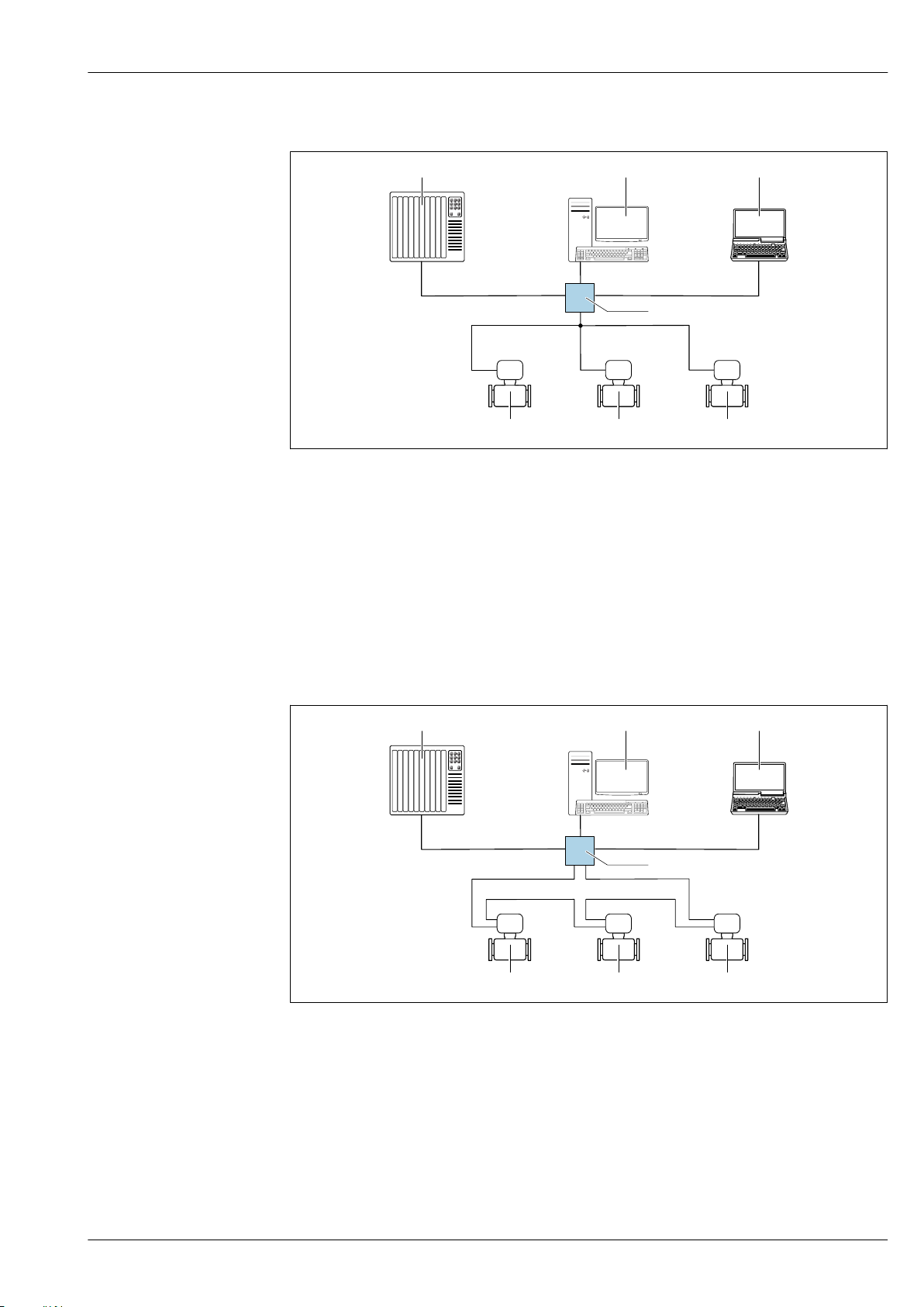
Proline Promass P 300
4
21 3
5 5 5
4
21 3
5
5 5
Star topology
A0032078
65 Options for remote operation via EtherNet/IP network: star topology
1 Automation system, e.g. "RSLogix" (Rockwell Automation)
2 Workstation for measuring device operation: with Custom Add-On Profile for "RSLogix 5000" (Rockwell
Automation) or with Electronic Data Sheet (EDS)
3 Computer with Web browser (e.g. Internet Explorer) for accessing the integrated device Web server or
computer with operating tool (e.g. FieldCare, DeviceCare) with COM DTM "CDI Communication TCP/IP"
4 Ethernet switch
5 Measuring device
Ring topology
The device is integrated via the terminal connection for signal transmission (output 1) and the
service interface (CDI-RJ45).
66 Options for remote operation via EtherNet/IP network: ring topology
1 Automation system, e.g. "RSLogix" (Rockwell Automation)
2 Workstation for measuring device operation: with Custom Add-On Profile for "RSLogix 5000" (Rockwell
Automation) or with Electronic Data Sheet (EDS)
3 Computer with Web browser (e.g. Internet Explorer) for accessing the integrated device Web server or
computer with operating tool (e.g. FieldCare, DeviceCare) with COM DTM "CDI Communication TCP/IP"
4 Ethernet switch
5 Measuring device
A0033725
Via PROFINET network
This communication interface is available in device versions with PROFINET.
Endress+Hauser 95
Page 96
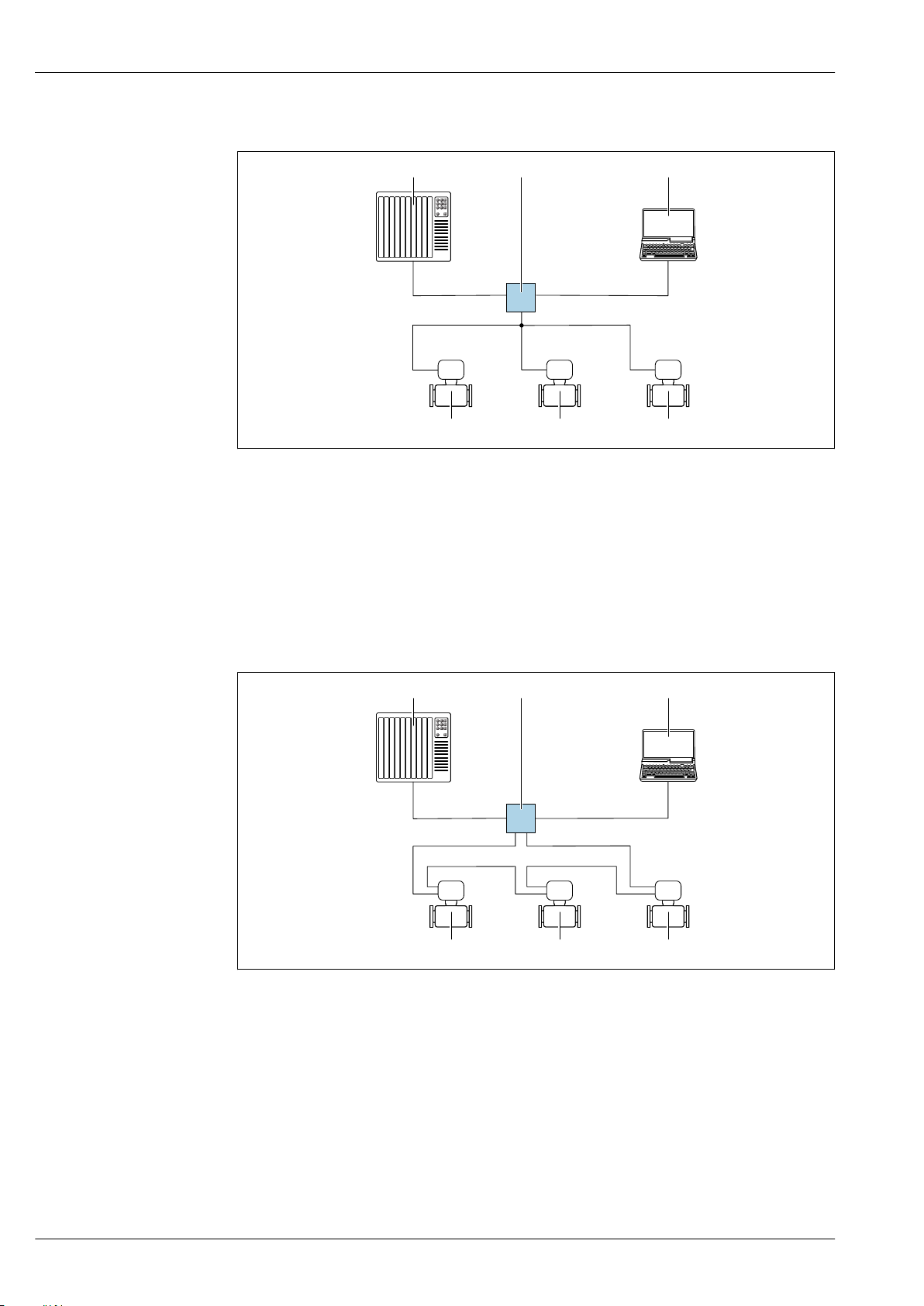
Proline Promass P 300
31 2
4 4 4
3
1 2
4 4 4
Star topology
67 Options for remote operation via PROFINET network: star topology
1 Automation system, e.g. Simatic S7 (Siemens)
2 Computer with Web browser (e.g. Internet Explorer) for accessing the integrated device Web server or
computer with operating tool (e.g. FieldCare, DeviceCare, SIMATIC PDM) with COM DTM "CDI Communication
TCP/IP"
3 Switch, e.g. Scalance X204 (Siemens)
4 Measuring device
A0026545
Ring topology
This communication interface is available in device versions with PROFINET.
68 Options for remote operation via PROFINET network: ring topology
1 Automation system, e.g. Simatic S7 (Siemens)
2 Computer with Web browser (e.g. Internet Explorer) for accessing the integrated device Web server or
computer with operating tool (e.g. FieldCare, DeviceCare, SIMATIC PDM) with COM DTM "CDI Communication
TCP/IP"
3 Switch, e.g. Scalance X204 (Siemens)
4 Measuring device
A0033719
96 Endress+Hauser
Page 97
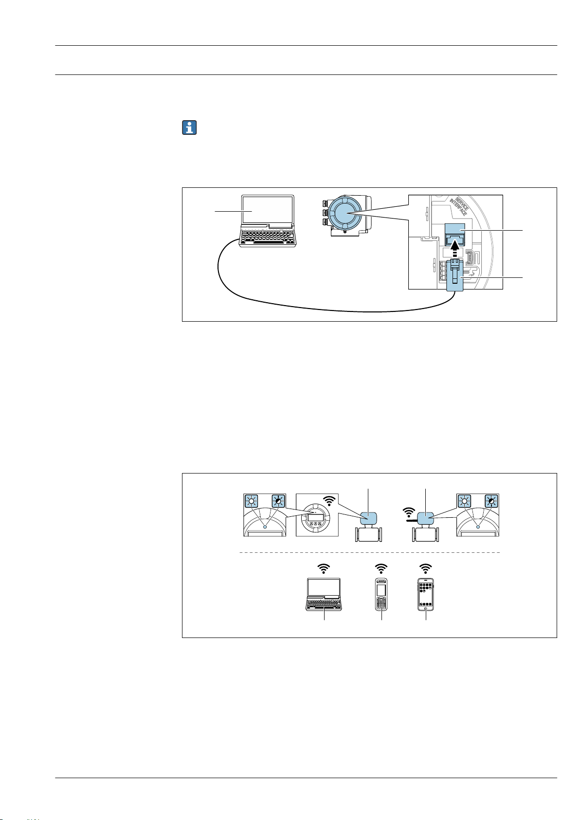
Proline Promass P 300
2
3
213
4
3
4
5 6 7
Service interface Via service interface (CDI-RJ45)
A point-to-point connection can be established to configure the device onsite. With the housing
open, the connection is established directly via the service interface (CDI-RJ45) of the device.
An adapter for RJ45 and the M12 connector is optionally available:
Order code for "Accessories", option NB: "Adapter RJ45 M12 (service interface)"
The adapter connects the service interface (CDI-RJ45) to an M12 connector mounted in the
cable entry. Therefore the connection to the service interface can be established via an M12
connector without opening the device.
A0027563
69 Connection via service interface (CDI-RJ45)
1 Computer with Web browser (e.g. Microsoft Internet Explorer, Microsoft Edge) for accessing the integrated
device Web server or with "FieldCare", "DeviceCare" operating tool with COM DTM "CDI Communication TCP/IP"
or Modbus DTM
2 Standard Ethernet connecting cable with RJ45 connector
3 Service interface (CDI-RJ45) of the measuring device with access to the integrated Web server
Via WLAN interface
The optional WLAN interface is available on the following device version:
Order code for "Display; operation", option G "4-line, illuminated, graphic display; touch control +
WLAN"
1 Transmitter with integrated WLAN antenna
2 Transmitter with external WLAN antenna
3 LED lit constantly: WLAN reception is enabled on measuring device
4 LED flashing: WLAN connection established between operating unit and measuring device
5 Computer with WLAN interface and Web browser (e.g. Microsoft Internet Explorer, Microsoft Edge) for
6 Mobile handheld terminal with WLAN interface and Web browser (e.g. Microsoft Internet Explorer, Microsoft
7 Smart phone or tablet (e.g. Field Xpert SMT70)
Endress+Hauser 97
accessing the integrated device Web server or with operating tool (e.g. FieldCare, DeviceCare)
Edge) for accessing the integrated device Web server or operating tool (e.g. FieldCare, DeviceCare)
A0034570
Page 98
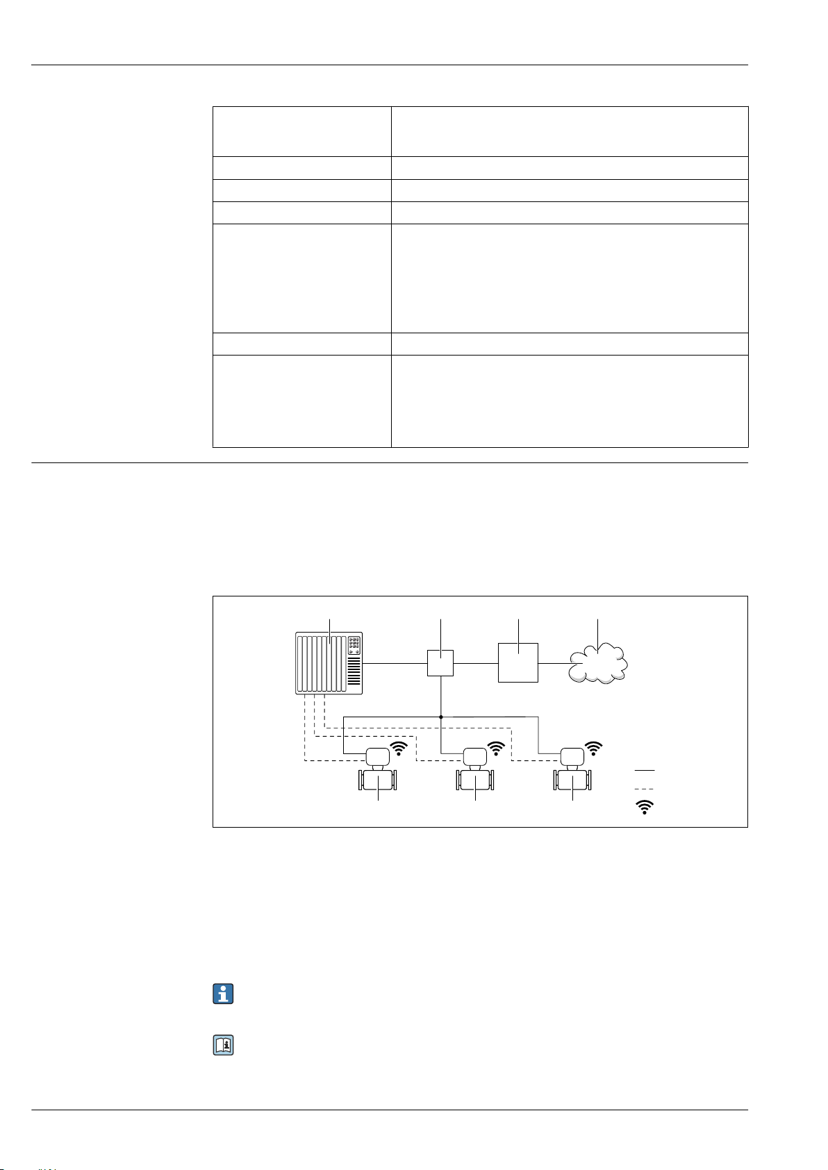
Proline Promass P 300
21 3
5 5 5
4
6
7
8
Function WLAN: IEEE 802.11 b/g (2.4 GHz)
• Access point with DHCP server (default setting)
• Network
Encryption WPA2-PSK AES-128 (in accordance with IEEE 802.11i)
Configurable WLAN channels 1 to 11
Degree of protection IP67
Available antennas • Internal antenna
• External antenna (optional)
In the event of poor transmission/reception conditions at the place of
installation.
Available as an accessory → 107.
Only one antenna active in each case!
Max. range 50 m (164 ft)
Materials:
External WLAN antenna
• Antenna: ASA plastic (acrylic ester-styrene-acrylonitrile) and nickelplated brass
• Adapter: Stainless steel and nickel-plated brass
• Cable: Polyethylene
• Connector: Nickel-plated brass
• Angle bracket: Stainless steel
Network integration
With the optional OPC-UA-Server application package, the device can be integrated into an Ethernet
network via the service interface (CDI-RJ45 and WLAN) and communicate with OPC-UA clients. If
the device is used in this way, IT security must be considered.
For permanent access to device data and for device configuration via the Web server, the device is
incorporated directly in a network via the service interface (CDI-RJ45). In this way, the device can be
accessed any time from the control station. The measured values are processed separately via the
inputs and outputs through the automation system.
1 Automation system, e.g. Simatic S7 (Siemens)
2 Ethernet switch
3 Edge Gateway
4 Cloud
5 Measuring device
6 Ethernet network
7 Measured values via inputs and outputs
8 Optional WLAN interface
A0033618
The optional WLAN interface is available on the following device version:
Order code for "Display; operation", option G "4-line, illuminated, graphic display; touch control +
WLAN"
Special Documentation for the OPC-UA-Server application package → 111.
98 Endress+Hauser
Page 99
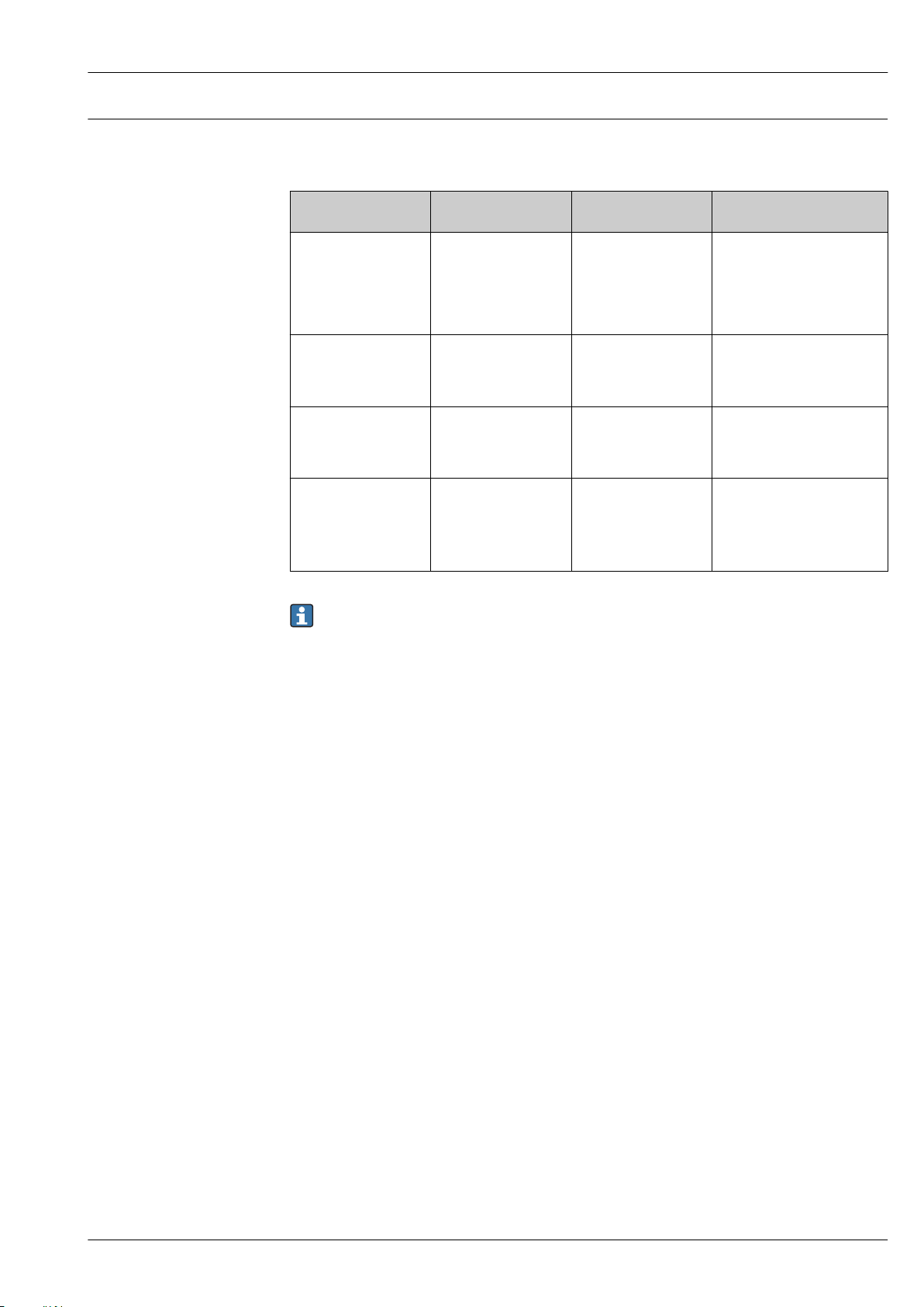
Proline Promass P 300
Supported operating tools
Different operating tools can be used for local or remote access to the measuring device. Depending
on the operating tool used, access is possible with different operating units and via a variety of
interfaces.
Supported operating
tools
Web browser Notebook, PC or tablet
DeviceCare SFE100 Notebook, PC or tablet
FieldCare SFE500 Notebook, PC or tablet
Device Xpert Field Xpert SFX
Operating unit Interface Additional information
with Web browser
with Microsoft Windows
system
with Microsoft Windows
system
100/350/370
• CDI-RJ45 service
interface
• WLAN interface
• Ethernet-based
fieldbus (EtherNet/IP,
PROFINET)
• CDI-RJ45 service
interface
• WLAN interface
• Fieldbus protocol
• CDI-RJ45 service
interface
• WLAN interface
• Fieldbus protocol
HART and
FOUNDATION Fieldbus
fieldbus protocol
Special Documentation for
device → 111
→ 109
→ 109
Operating Instructions
BA01202S
Device description files:
Use update function of
handheld terminal
Other operating tools based on FDT technology with a device driver such as DTM/iDTM or
DD/EDD can be used for device operation. These operating tools are available from the
individual manufacturers. Integration into the following operating tools, among others, is
supported:
• FactoryTalk AssetCentre (FTAC) by Rockwell Automation → www.rockwellautomation.com
• Process Device Manager (PDM) by Siemens → www.siemens.com
• Asset Management Solutions (AMS) by Emerson → www.emersonprocess.com
• FieldCommunicator 375/475 by Emerson → www.emersonprocess.com
• Field Device Manager (FDM) by Honeywell → www.honeywellprocess.com
• FieldMate by Yokogawa → www.yokogawa.com
• PACTWare → www.pactware.com
The associated device description files are available at: www.endress.com → Downloads
Web server
Thanks to the integrated Web server, the device can be operated and configured via a Web browser
and via a service interface (CDI-RJ45) or via a WLAN interface. The structure of the operating menu
is the same as for the local display. In addition to the measured values, status information on the
device is also displayed and allows the user to monitor the status of the device. Furthermore the
device data can be managed and the network parameters can be configured.
A device that has a WLAN interface (can be ordered as an option) is required for the WLAN
connection: order code for "Display; operation", option G "4-line, illuminated; touch control + WLAN".
The device acts as an Access Point and enables communication by computer or a mobile handheld
terminal.
Supported functions
Data exchange between the operating unit (such as a notebook for example) and the measuring
device:
– Upload the configuration from the measuring device (XML format, configuration backup)
– Save the configuration to the measuring device (XML format, restore configuration)
– Export event list (.csv file)
– Export parameter settings (.csv file or PDF file, document the measuring point configuration)
– Export the Heartbeat verification log (PDF file, only available with the "Heartbeat Verification"
application package)
Endress+Hauser 99
Page 100
Proline Promass P 300
– Flash firmware version for device firmware upgrade, for instance
– Download driver for system integration
– Visualize up to 1000 saved measured values (only available with the Extended HistoROM
application package → 105)
Web server special documentation → 111
HistoROM data management
The measuring device features HistoROM data management. HistoROM data management
comprises both the storage and import/export of key device and process data, making operation and
servicing far more reliable, secure and efficient.
When the device is delivered, the factory settings of the configuration data are stored as a
backup in the device memory. This memory can be overwritten with an updated data record, for
example after commissioning.
Additional information on the data storage concept
There are different types of data storage units in which device data are stored and used by the device:
Device memory T-DAT S-DAT
Available data • Event logbook such as diagnostic events for example
• Parameter data record backup
• Device firmware package
• Driver for system integration for exporting via Web
server, e.g:
– GSD for PROFIBUS DP
– GSD for PROFIBUS PA
– GSDML for PROFINET
– EDS for EtherNet/IP
– DD for FOUNDATION Fieldbus
Storage location Fixed on the user interface board in the connection
compartment
• Measured value logging
("Extended HistoROM" order
option)
• Current parameter data record
(used by firmware at run time)
• Peakhold indicator (min/max
values)
• Totalizer values
Attachable to the user interface
board in the connection
compartment
• Sensor data: nominal diameter
etc.
• Serial number
• Calibration data
• Device configuration (e.g. SW
options, fixed I/O or multi I/O)
In the sensor plug in the transmitter
neck part
Data backup
Automatic
• The most important device data (sensor and transmitter) are automatically saved in the DAT
modules
• If the transmitter or measuring device is replaced: once the T-DAT containing the previous device
data has been exchanged, the new measuring device is ready for operation again immediately
without any errors
• If the sensor is replaced: once the sensor has been replaced, new sensor data are transferred from
the S-DAT in the measuring device and the measuring device is ready for operation again
immediately without any errors
• If exchanging the electronics module (e.g. I/O electronics module): Once the electronics module
has been replaced, the software of the module is compared against the current device firmware.
The module software is upgraded or downgraded where necessary. The electronics module is
available for use immediately afterwards and no compatibility problems occur.
Manual
Additional parameter data record (complete parameter settings) in the integrated device memory
HistoROM backup for:
• Data backup function
Backup and subsequent restoration of a device configuration in the device memory HistoROM
backup
• Data comparison function
Comparison of the current device configuration with the device configuration saved in the device
memory HistoROM backup
100 Endress+Hauser
 Loading...