

Page 1
BA01058D/06/EN/02.13
71211168
Valid as of version
01.02.zz (Device firmware)
Products Solutions Services
Operating Instructions
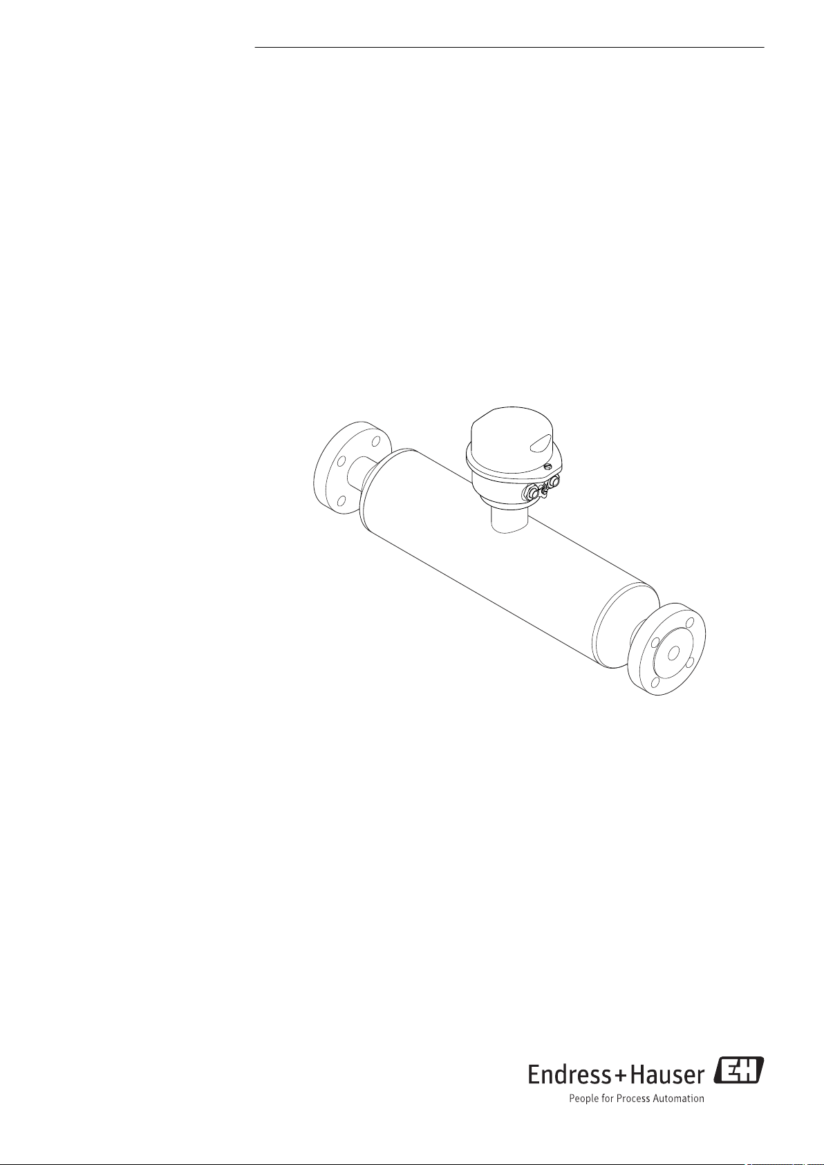
Proline Promass I 100
Modbus RS485
Coriolis flowmeter
Page 2

Proline Promass I 100 Modbus RS485
• Make sure the document is stored in a safe place such that it is always available when
working on or with the device.
• To avoid danger to individuals or the facility, read the "Basic safety instructions" section
carefully, as well as all other safety instructions in the document that are specific to
working procedures.
• The manufacturer reserves the right to modify technical data in line with technological
developments without prior notice. Your Endress+Hauser sales center will supply you
with current information and updates to this manual.
2 Endress+Hauser
Page 3

Proline Promass I 100 Modbus RS485 Table of contents
Table of contents
1 Document information .............. 5
1.1 Document function ..................... 5
1.2 Symbols used .......................... 5
1.2.1 Safety symbols .................. 5
1.2.2 Electrical symbols ................ 5
1.2.3 Tool symbols .................... 6
1.2.4 Symbols for certain types of
information .................... 6
1.2.5 Symbols in graphics ............... 6
1.3 Documentation ........................ 7
1.3.1 Standard documentation ........... 7
1.3.2 Supplementary device-dependent
documentation .................. 7
1.4 Registered trademarks ................... 7
2 Basic safety instructions ............ 8
2.1 Requirements for the personnel ............ 8
2.2 Designated use ........................ 8
2.3 Workplace safety ....................... 9
2.4 Operational safety ...................... 9
2.5 Product safety ......................... 9
3 Product description ................ 10
3.1 Product design ........................ 10
3.1.1 Device version with Modbus RS485
communication type ............. 10
4 Incoming acceptance and product
identification ..................... 11
4.1 Incoming acceptance ................... 11
4.2 Product identification ................... 12
4.2.1 Transmitter nameplate ........... 12
4.2.2 Sensor nameplate ............... 13
4.2.3 Promass 100 safety barrier -
nameplate .................... 14
4.2.4 Symbols on measuring device ...... 14
5 Storage and transport ............. 15
5.1 Storage conditions ..................... 15
5.2 Transporting the product ................ 15
5.3 Packaging disposal ..................... 16
6 Installation ....................... 17
6.1 Installation conditions .................. 17
6.1.1 Mounting position ............... 17
6.1.2 Requirements from environment and
process ....................... 19
6.1.3 Special mounting instructions ...... 20
6.2 Mounting the measuring device ........... 22
6.2.1 Required tools .................. 22
6.2.2 Preparing the measuring device ..... 22
6.2.3 Mounting the measuring device ..... 22
6.3 Post-installation check .................. 23
7 Electrical connection .............. 24
7.1 Connection conditions .................. 24
7.1.1 Required tools .................. 24
7.1.2 Requirements for connecting cable ... 24
7.1.3 Terminal assignment ............. 26
7.1.4 Pin assignment, device plug ........ 28
7.1.5 Shielding and grounding .......... 29
7.1.6 Preparing the measuring device ..... 29
7.2 Connecting the measuring device .......... 29
7.2.1 Connecting the transmitter ........ 30
7.2.2 Connecting the Safety Barrier
Promass 100 ................... 31
7.3 Hardware settings ..................... 32
7.3.1 Enabling the terminating resistor .... 32
7.4 Ensuring the degree of protection .......... 32
7.5 Post-connection check .................. 33
8 Operation options ................. 34
8.1 Overview of operation options ............ 34
8.2 Structure and function of the operating
menu .............................. 35
8.2.1 Structure of the operating menu .... 35
8.2.2 Operating philosophy ............ 36
8.3 Access to the operating menu via the
operating tool ........................ 37
8.3.1 Connecting the operating tool ...... 37
8.3.2 FieldCare ..................... 37
9 System integration ................ 39
9.1 Overview of device description files ......... 39
9.1.1 Current version data for the device ... 39
9.1.2 Operating tools ................. 39
9.2 Modbus RS485 information .............. 39
9.2.1 Function codes ................. 39
9.2.2 Register information ............. 40
9.2.3 Response time .................. 40
9.2.4 Modbus data map ............... 40
10 Commissioning .................... 43
10.1 Function check ....................... 43
10.2 Establishing a connection via FieldCare ...... 43
10.3 Configuring the measuring device .......... 43
10.3.1 Setting the system units .......... 43
10.3.2 Selecting and setting the medium ... 46
10.3.3 Configuring communication
interface ...................... 47
10.3.4 Configuring the low flow cut off ..... 49
10.3.5 Configuring the partial filled pipe
detection ..................... 50
Endress+Hauser 3
Page 4

Table of contents Proline Promass I 100 Modbus RS485
10.4 Advanced settings ..................... 51
10.4.1 Defining the tag name ............ 51
10.4.2 Calculated values ................ 51
10.4.3 Carrying out a sensor adjustment .... 52
10.4.4 Configuring the totalizer .......... 53
10.5 Simulation ........................... 54
10.5.1 Parameter overview with brief
description .................... 55
10.6 Protecting settings from unauthorized
access .............................. 55
10.6.1 Write protection via write protection
switch ........................ 55
11 Operation ......................... 57
11.1 Read device locking status ............... 57
11.2 Reading measured values ................ 57
11.2.1 Process variables ................ 57
11.2.2 Totalizer ...................... 58
11.3 Adapting the measuring device to the process
conditions ........................... 59
11.4 Performing a totalizer reset .............. 59
12 Diagnostics and troubleshooting ... 61
12.1 General troubleshooting ................. 61
12.2 Diagnostic information via light emitting
diodes .............................. 61
12.2.1 Transmitter .................... 61
12.2.2 Safety Barrier Promass 100 ........ 62
12.3 Diagnostic information in FieldCare ........ 62
12.3.1 Diagnostic options ............... 62
12.3.2 Calling up remedy information ...... 63
12.4 Diagnostic information via communication
interface ............................ 63
12.4.1 Reading out diagnostic information .. 63
12.4.2 Configuring error response mode .... 64
12.5 Adapting the diagnostic information ....... 64
12.5.1 Adapting the diagnostic behavior .... 64
12.6 Overview of diagnostic information ........ 65
12.7 Pending diagnostic events ............... 67
12.8 Diagnostic list ........................ 67
12.9 Event logbook ........................ 68
12.9.1 Event history ................... 68
12.9.2 Filtering the event logbook ........ 68
12.9.3 Overview of information events ..... 68
12.10 Resetting the measuring device ........... 69
12.11 Device information .................... 69
12.12 Firmware history ...................... 70
14 Repair ............................ 72
14.1 General notes ........................ 72
14.2 Spare parts .......................... 72
14.3 Endress+Hauser services ................ 72
14.4 Return .............................. 72
14.5 Disposal ............................ 72
14.5.1 Removing the measuring device ..... 72
14.5.2 Disposing of the measuring device ... 73
15 Accessories ....................... 74
15.1 Device-specific accessories ............... 74
15.1.1 For the sensor .................. 74
15.2 Communication-specific accessories ........ 74
15.3 Service-specific accessories ............... 75
15.4 System components .................... 75
16 Technical data .................... 76
16.1 Application .......................... 76
16.2 Function and system design .............. 76
16.3 Input ............................... 76
16.4 Output ............................. 78
16.5 Power supply ......................... 80
16.6 Performance characteristics .............. 81
16.7 Installation .......................... 85
16.8 Environment ......................... 85
16.9 Process ............................. 86
16.10 Mechanical construction ................ 88
16.11 Operability .......................... 90
16.12 Certificates and approvals ............... 90
16.13 Application packages ................... 92
16.14 Accessories .......................... 93
16.15 Documentation ....................... 93
17 Appendix ......................... 94
17.1 Overview of the operating menu ........... 94
Index ................................. 110
13 Maintenance ...................... 71
13.1 Maintenance tasks ..................... 71
13.1.1 Exterior cleaning ................ 71
13.1.2 Interior cleaning ................ 71
13.2 Measuring and test equipment ............ 71
13.3 Endress+Hauser services ................ 71
4 Endress+Hauser
Page 5
Proline Promass I 100 Modbus RS485 Document information
DANGER
WARNING
CAUTION
NOTICE
1 Document information
1.1 Document function
These Operating Instructions contain all the information that is required in various phases
of the life cycle of the device: from product identification, incoming acceptance and
storage, to mounting, connection, operation and commissioning through to
troubleshooting, maintenance and disposal.
1.2 Symbols used
1.2.1 Safety symbols
Symbol Meaning
DANGER!
A0011189-EN
A0011190-EN
A0011191-EN
A0011192-EN
This symbol alerts you to a dangerous situation. Failure to avoid this situation will result in
serious or fatal injury.
WARNING!
This symbol alerts you to a dangerous situation. Failure to avoid this situation can result in
serious or fatal injury.
CAUTION!
This symbol alerts you to a dangerous situation. Failure to avoid this situation can result in
minor or medium injury.
NOTICE!
This symbol contains information on procedures and other facts which do not result in
personal injury.
1.2.2 Electrical symbols
Symbol Meaning
Direct current
A0011197
A terminal to which DC voltage is applied or through which direct current flows.
Alternating current
A0011198
A terminal to which alternating voltage is applied or through which alternating current flows.
Direct current and alternating current
• A terminal to which alternating voltage or DC voltage is applied.
A0017381
• A terminal through which alternating current or direct current flows.
Ground connection
A grounded terminal which, as far as the operator is concerned, is grounded via a grounding
A0011200
system.
Protective ground connection
A terminal which must be connected to ground prior to establishing any other connections.
A0011199
Equipotential connection
A connection that has to be connected to the plant grounding system: This may be a potential
A0011201
equalization line or a star grounding system depending on national or company codes of practice.
Endress+Hauser 5
Page 6
Document information Proline Promass I 100 Modbus RS485
,…,
,…,
-
.
1.2.3 Tool symbols
Symbol Meaning
Allen key
A0011221
Open-ended wrench
A0011222
1.2.4 Symbols for certain types of information
Symbol Meaning
Allowed
Indicates procedures, processes or actions that are allowed.
A0011182
Preferred
Indicates procedures, processes or actions that are preferred.
A0011183
Forbidden
Indicates procedures, processes or actions that are forbidden.
A0011184
Tip
Indicates additional information.
A0011193
Reference to documentation
Refers to the corresponding device documentation.
A0011194
Reference to page
Refers to the corresponding page number.
A0011195
Reference to graphic
Refers to the corresponding graphic number and page number.
A0011196
Series of steps
Result of a sequence of actions
Help in the event of a problem
A0013562
1.2.5 Symbols in graphics
Symbol Meaning
1, 2, 3,... Item numbers
Series of steps
A, B, C, ... Views
A-A, B-B, C-C, ... Sections
Flow direction
A0013441
Hazardous area
Indicates a hazardous area.
A0011187
Safe area (non-hazardous area)
Indicates a non-hazardous area.
A0011188
6 Endress+Hauser
Page 7
Proline Promass I 100 Modbus RS485 Document information
1.3 Documentation
The following document types are available:
• On the CD-ROM supplied with the device
• In the Download Area of the Endress+Hauser Internet site: www.endress.com
Download
For a detailed list of the individual documents along with the documentation code
( 93)
1.3.1 Standard documentation
Document type Purpose and content of the document
Technical Information Planning aid for your device
The document contains all the technical data on the device and provides
an overview of the accessories and other products that can be ordered for
the device.
Brief Operating Instructions Guide that takes you quickly to the 1st measured value
The Brief Operating Instructions contain all the essential information
from incoming acceptance to initial commissioning.
Modbus RS485 register information Reference for Modbus RS485 register information
The document provides Modbus-specific information for each individual
parameter in the operating menu.
1.3.2 Supplementary device-dependent documentation
Additional documents are supplied depending on the device version ordered: Always
comply strictly with the instructions in the supplementary documentation. The
supplementary documentation is an integral part of the device documentation.
1.4 Registered trademarks
Modbus
Registered trademark of SCHNEIDER AUTOMATION, INC.
TRI-CLAMP
Registered trademark of Ladish & Co., Inc., Kenosha, USA
Applicator®, FieldCare®, Field XpertTM, HistoROM®, TMB®, Heartbeat Technology
Registered or registration-pending trademarks of the Endress+Hauser Group
®
®
TM
Endress+Hauser 7
Page 8

Basic safety instructions Proline Promass I 100 Modbus RS485
2 Basic safety instructions
2.1 Requirements for the personnel
The personnel for installation, commissioning, diagnostics and maintenance must fulfill
the following requirements:
Trained, qualified specialists must have a relevant qualification for this specific function
‣
and task
Are authorized by the plant owner/operator
‣
Are familiar with federal/national regulations
‣
Before beginning work, the specialist staff must have read and understood the
‣
instructions in the Operating Instructions and supplementary documentation as well as
in the certificates (depending on the application)
Following instructions and basic conditions
‣
The operating personnel must fulfill the following requirements:
Being instructed and authorized according to the requirements of the task by the
‣
facility's owner-operator
Following the instructions in these Operating Instructions
‣
2.2 Designated use
Application and media
The measuring device described in these Instructions is intended only for flow
measurement of liquids and gases.
Depending on the version ordered, the measuring device can also measure potentially
explosive, flammable, poisonous and oxidizing media.
Measuring devices for use in hazardous areas, in hygienic applications or in applications
where there is an increased risk due to process pressure, are labeled accordingly on the
nameplate.
To ensure that the measuring device remains in proper condition for the operation time:
Only use the measuring device in full compliance with the data on the nameplate and
‣
the general conditions listed in the Operating Instructions and supplementary
documentation.
Based on the nameplate, check whether the ordered device is permitted for the
‣
intended use in the hazardous area (e.g. explosion protection, pressure vessel safety).
Use the measuring device only for media against which the process-wetted materials
‣
are adequately resistant.
If the measuring device is not operated at atmospheric temperature, compliance with
‣
the relevant basic conditions specified in the device documentation provided (on the
CD-ROM) is absolutely essential.
Incorrect use
Non-designated use can compromise safety. The manufacturer is not liable for damage
caused by improper or non-designated use.
NOTICE
Danger of breakage of the measuring tube due to corrosive or abrasive fluids.
Housing breakage due to mechanical overload possible!
Verify the compatibility of the process fluid with the measuring tube material.
‣
Ensure the resistance of all fluid-wetted materials in the process.
‣
Observe the specified maximum process pressure.
‣
Verification for borderline cases:
For special fluids and fluids for cleaning, Endress+Hauser is glad to provide assistance
‣
in verifying the corrosion resistance of fluid-wetted materials, but does not accept any
8 Endress+Hauser
Page 9

Proline Promass I 100 Modbus RS485 Basic safety instructions
warranty or liability as minute changes in the temperature, concentration or level of
contamination in the process can alter the corrosion resistance properties.
Residual risks
The external surface temperature of the housing can increase by max. 20 K due to the
power consumption of the electronic components. Hot process fluids passing through the
measuring device will further increase the surface temperature of the housing. The surface
of the sensor, in particular, can reach temperatures which are close to the fluid
temperature.
Possible burn hazard due to fluid temperatures!
For elevated fluid temperature, ensure protection against contact to prevent burns.
‣
2.3 Workplace safety
For work on and with the device:
Wear the required personal protective equipment according to federal/national
‣
regulations.
For welding work on the piping:
Do not ground the welding unit via the measuring device.
‣
2.4 Operational safety
Risk of injury.
Operate the device in proper technical condition and fail-safe condition only.
‣
The operator is responsible for interference-free operation of the device.
‣
Conversions to the device
Unauthorized modifications to the device are not permitted and can lead to unforeseeable
dangers.
If, despite this, modifications are required, consult with Endress+Hauser.
‣
Repair
To ensure continued operational safety and reliability,
Carry out repairs on the device only if they are expressly permitted.
‣
Observe federal/national regulations pertaining to repair of an electrical device.
‣
Use original spare parts and accessories from Endress+Hauser only.
‣
2.5 Product safety
This measuring device is designed in accordance with good engineering practice to meet
state-of-the-art safety requirements, has been tested, and left the factory in a condition in
which they are safe to operate.
It meets general safety standards and legal requirements. It also complies with the EC
directives listed in the device-specific EC Declaration of Conformity. Endress+Hauser
confirms this by affixing the CE mark to the device.
Endress+Hauser 9
Page 10
Product description Proline Promass I 100 Modbus RS485
2
3
4
1
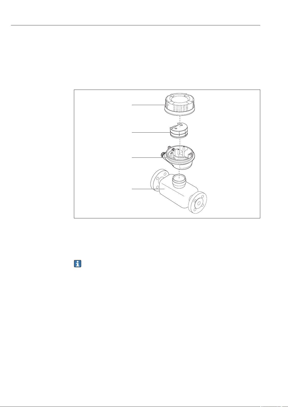
3 Product description
3.1 Product design
3.1.1 Device version with Modbus RS485 communication type
A0017609
1 Important components of a measuring device
1 Transmitter housing cover
2 Main electronics module for Modbus RS485
3 Transmitter housing
4 Sensor
In the case of the device version with Modbus RS485 intrinsically safe, the Safety
Barrier Promass 100 forms part of the scope of supply.
10 Endress+Hauser
Page 11
Proline Promass I 100 Modbus RS485 Incoming acceptance and product identification
1
+
2
1
+
2
4 Incoming acceptance and product
identification
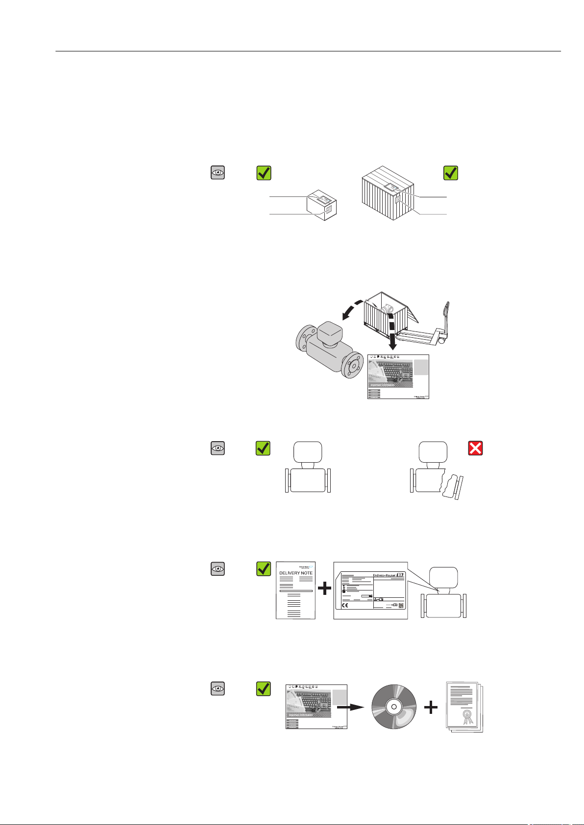
4.1 Incoming acceptance
A0015502
A0013843
Is the order code on the delivery note (1) identical to the order code on the product sticker
(2)?
A0013695
A0015502
A0013698
Are the goods undamaged?
A0015502
A0013699
Do the nameplate data match the ordering information on the delivery note?
A0015502
A0013697
Is the CD-ROM with the Technical Documentation and documents present?
Endress+Hauser 11
Page 12
Incoming acceptance and product identification Proline Promass I 100 Modbus RS485
i
1
2
3
4
5
6
7
8
9
101112
Order code:
Ext. ord. cd.:
Ser. no.:
13
If one of the conditions is not satisfied, contact your Endress+Hauser Sales Center.
4.2 Product identification
The following options are available for identification of the measuring device:
• Nameplate specifications
• Order code with breakdown of the device features on the delivery note
• Enter serial numbers from nameplates in W@M Device Viewer
www.endress.com/deviceviewer): All information about the measuring device is
(
displayed.
For an overview of the scope of the Technical Documentation provided, refer to the
following:
• The "Additional standard documentation on the device" ( 7) and "Supplementary
device-dependent documentation" ( 7) sections
• The W@M Device Viewer: Enter the serial number from the nameplate
(www.endress.com/deviceviewer)
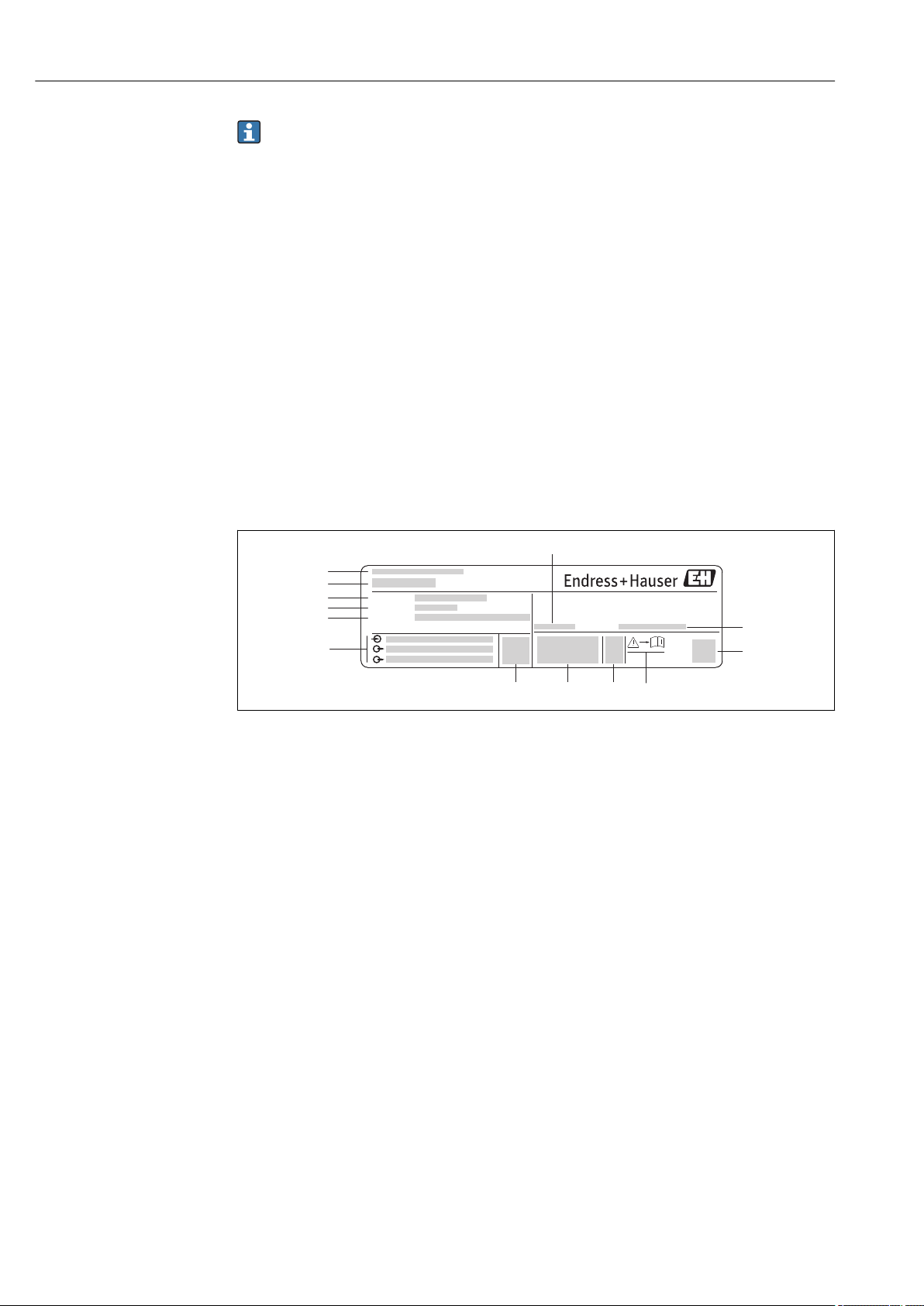
4.2.1 Transmitter nameplate
2 Example of a transmitter nameplate
1 Manufacturing location
2 Name of the transmitter
3 Order code
4 Serial number
5 Extended order code
6 Electrical connection data, e.g. available inputs and outputs, supply voltage
7 Permitted ambient temperature range (Ta)
8 Degree of protection
9 2-D matrix code
10 Document number of safety-related supplementary documentation (→ 93)
11 Manufacturing date: year-month
12 CE mark, C-Tick
13 Firmware version (FW)
12 Endress+Hauser
A0017520
Page 13
Proline Promass I 100 Modbus RS485 Incoming acceptance and product identification
Ext. ord. cd.:
Order code:
Ser. no.:
Material:
Tm:
Size:
Ta:
Date:
6
10
11
1 2
3
4
5
Ptest:
7
8
12
Patents
16
17
19
18
13
15
9
14
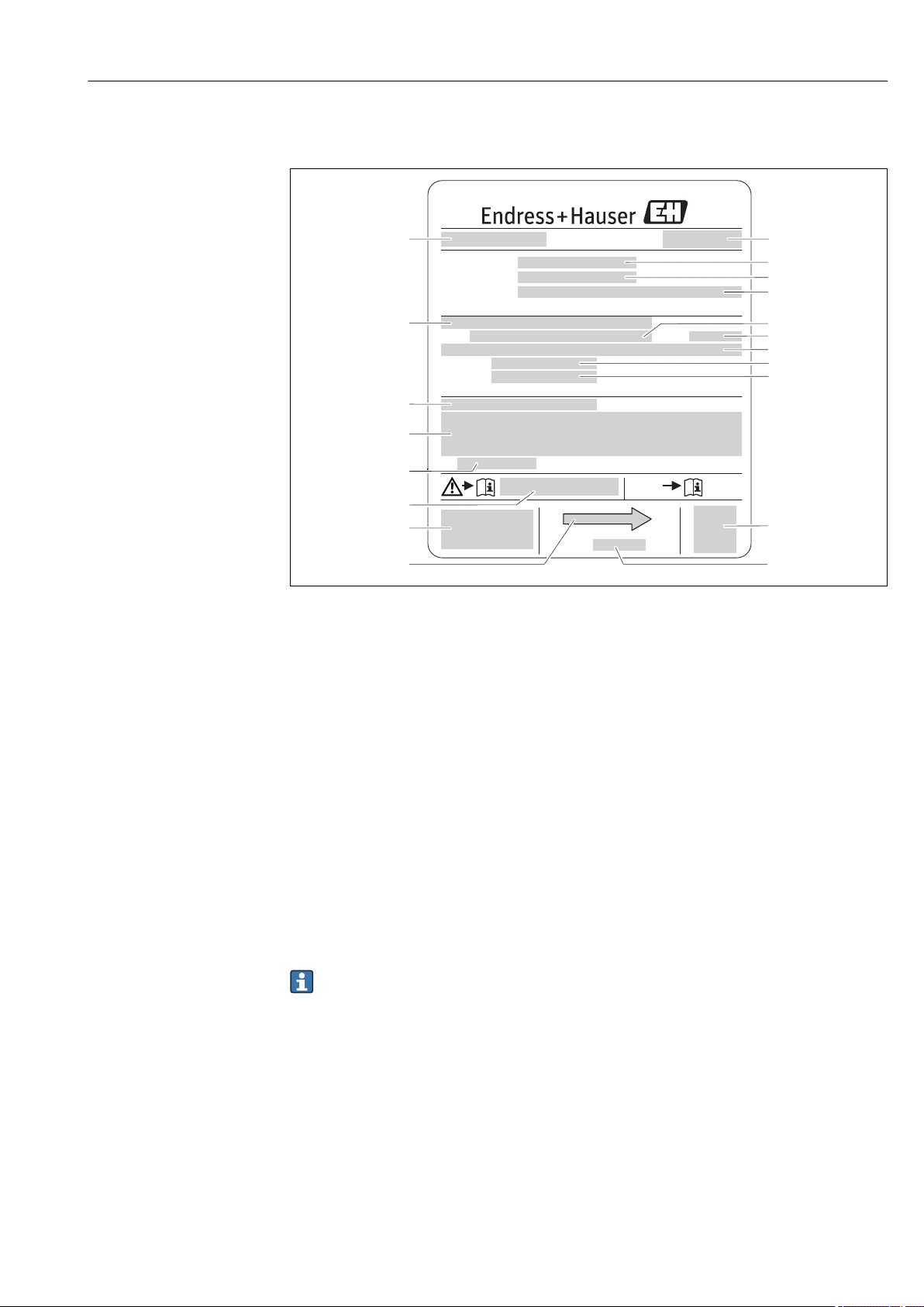
4.2.2 Sensor nameplate
3 Example of a sensor nameplate
1 Name of the sensor
2 Manufacturing location
3 Order code
4 Serial number (Ser. no.)
5 Extended order code (Ext. ord. cd.)
6 Flange nominal diameter/nominal pressure
7 Test pressure of the sensor
8 Nominal diameter of the sensor
9 Sensor-specific data: e.g. pressure range of secondary containment, wide-range density specification (special
density calibration)
10 Material of measuring tube and manifold
11 Medium temperature range
12 Degree of protection
13 Approval information for explosion protection and Pressure Equipment Directive
14 Permitted ambient temperature (Ta)
15 Document number of safety-related supplementary documentation (→ 93)
16 CE mark, C-Tick
17 Flow direction
18 Manufacturing date: year-month
19 2-D matrix code
Order code
The measuring device is reordered using the order code.
Extended order code
• The device type (product root) and basic specifications (mandatory features) are
always listed.
• Of the optional specifications (optional features), only the safety and approvalrelated specifications are listed (e.g. LA). If other optional specifications are also
ordered, these are indicated collectively using the # placeholder symbol (e.g. #LA#).
• If the ordered optional specifications do not include any safety and approval-related
specifications, they are indicated by the + placeholder symbol (e.g. XXXXXX-ABCDE
Endress+Hauser 13
+).
A0017923
Page 14
Incoming acceptance and product identification Proline Promass I 100 Modbus RS485
NON intrinsically safe circuit
(grey terminals)
Safe area
Safety Barrier
Promass 100
Intrinsically safe circuits
(blue terminals)
HAZARDOUS area
i
1
3
4
5
6
7
8
9
10
11
2
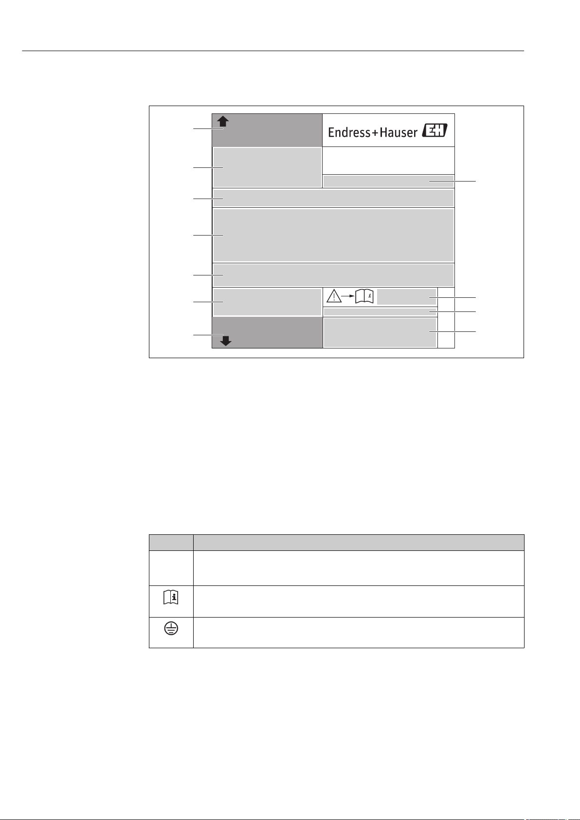
4.2.3 Promass 100 safety barrier - nameplate
A0017854
4 Example of a Safety Barrier Promass 100 nameplate
1 Non-hazardous area or zone 2/div. 2
2 Serial number, material number and 2-D matrix code of the Safety Barrier Promass 100
3 Electrical connection data, e.g. available inputs and outputs, supply voltage
4 Explosion protection approval information
5 Safety warning
6 Communication-specific information
7 Intrinsically safe area
8 Manufacturing location
9 Document number of safety-related supplementary documentation (→ 93)
10 Permitted ambient temperature (Ta)
11 CE mark, C-Tick
4.2.4 Symbols on measuring device
Symbol Meaning
WARNING!
This symbol alerts you to a dangerous situation. Failure to avoid this situation can result in serious
or fatal injury.
Reference to documentation
Refers to the corresponding device documentation.
A0011194
Protective ground connection
A terminal which must be connected to ground prior to establishing any other connections.
A0011199
14 Endress+Hauser
Page 15
Proline Promass I 100 Modbus RS485 Storage and transport
5 Storage and transport
5.1 Storage conditions
Observe the following notes for storage:
• Store in the original packaging to ensure protection from shock.
• Do not remove protective covers or protective caps installed on process connections.
They prevent mechanical damage to the sealing surfaces and fouling in the measuring
tube.
• Protect from direct sunlight to avoid unacceptably high surface temperatures.
• Storage temperature: –40 to +80 °C (–40 to +176 °F), preferable for +20 °C (+68 °F)
• Store in a dry and dust-free place.
• Do not store outdoors.
5.2 Transporting the product
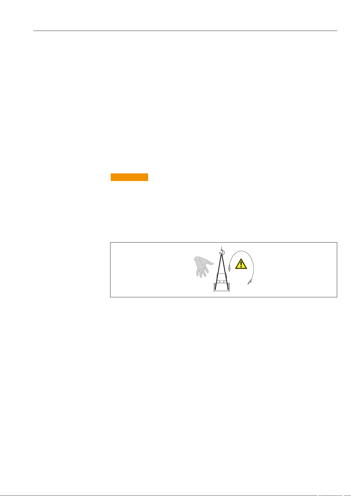
WARNING
Center of gravity of the measuring device is higher than the suspension points of the
webbing slings.
Risk of injury if the measuring device slips.
Secure the measuring device from rotating or slipping.
‣
Observe the weight specified on the packaging (stick-on label).
‣
Observe the transport instructions on the stick-on label on the electronics compartment
‣
cover.
Observe the following notes during transport:
• Transport the measuring device to the measuring point in the original packaging.
• Lifting gear
– Webbing slings: Do not use chains, as they could damage the housing.
– For wood crates, the floor structure enables these to be loaded lengthwise or broadside
using a forklift.
• For measuring device > DN 40 (1½ in): lift the measuring device using the webbing
slings at the process connections; do not lift at the transmitter housing.
• Do not remove protective covers or protective caps installed on process connections.
They prevent mechanical damage to the sealing surfaces and fouling in the measuring
tube.
A0015606
Endress+Hauser 15
Page 16

Storage and transport Proline Promass I 100 Modbus RS485
5.3 Packaging disposal
All packaging materials are environmentally friendly and 100% recyclable:
• Measuring device secondary packaging: polymer stretch film that conforms to EC
Directive 2002/95/EC (RoHS).
• Packaging:
– Wood crate, treated in accordance with ISPM 15 standard, which is confirmed by the
affixed IPPC logo.
or
– Carton in accordance with European Packaging Directive 94/62EC; recyclability is
confirmed by the affixed RESY symbol.
• Seaworthy packaging (optional): Wood crate, treated in accordance with ISPM 15
standard, which is confirmed by the affixed IPPC logo.
• Carrying and mounting hardware:
– Disposable plastic pallet
– Plastic straps
– Plastic adhesive strips
• Dunnage: Paper cushion
16 Endress+Hauser
Page 17
Proline Promass I 100 Modbus RS485 Installation
1
2
3
4
5
6 Installation
6.1 Installation conditions
No special measures such as supports are necessary. External forces are absorbed by the
construction of the device.
6.1.1 Mounting position
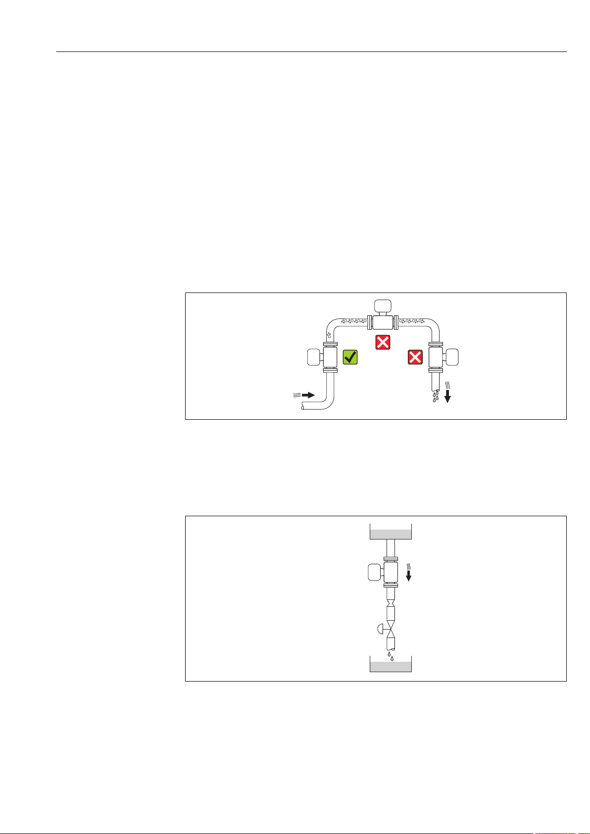
Mounting location
To prevent measuring errors arising from accumulation of gas bubbles in the measuring
tube, avoid the following mounting locations in the pipe:
• Highest point of a pipeline.
• Directly upstream of a free pipe outlet in a down pipe.
A0015595
Installation in down pipes
However, the following installation suggestion allows for installation in an open vertical
pipeline. Pipe restrictions or the use of an orifice with a smaller cross-section than the
nominal diameter prevent the sensor running empty while measurement is in progress.
A0015596
5 Installation in a down pipe (e.g. for batching applications)
1 Supply tank
2 Sensor
3 Orifice plate, pipe restriction
4 Valve
5 Batching tank
Endress+Hauser 17
Page 18
Installation Proline Promass I 100 Modbus RS485
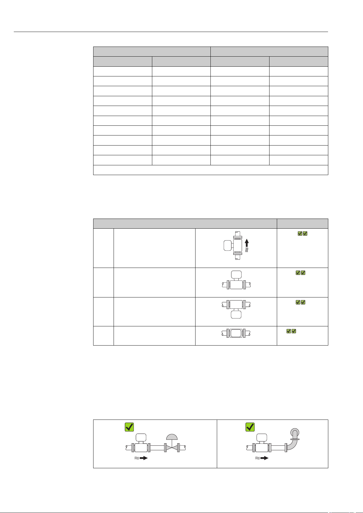
DN Ø orifice plate, pipe restriction
[mm] [in] [mm] [in]
8 ³⁄₈ 6 0.24
15 ½ 10 0.40
15 FB ½ FB 15 0.60
25 1 14 0.55
25 FB 1 FB 24 0.95
40 1½ 22 0.87
40 FB 1½ FB 35 1.38
50 2 28 1.10
50 FB 2 FB 54 2.13
80 3 50 1.97
FB = Full bore
Orientation
The direction of the arrow on the sensor nameplate helps you to install the sensor
according to the flow direction (direction of medium flow through the piping).
Orientation Recommendation
A Vertical orientation
A0015591
B Horizontal orientation, transmitter
head up
C Horizontal orientation, transmitter
head down
D Horizontal orientation, transmitter
head at side
A0015589
A0015590
A0015592
1)
Exception:
2)
Exception:
( 20)
1) Applications with low process temperatures may reduce the ambient temperature. To maintain the
minimum ambient temperature for the transmitter, this orientation is recommended.
2) Applications with high process temperatures may increase the ambient temperature. To maintain the
maximum ambient temperature for the transmitter, this orientation is recommended.
Inlet and outlet runs
No special precautions need to be taken for fittings which create turbulence, such as
valves, elbows or T-pieces, as long as no cavitation occurs ( 19).
A0015597 A0015598
18 Endress+Hauser
Page 19
Proline Promass I 100 Modbus RS485 Installation
Installation dimensions
For the dimensions and installation lengths of the device, see the "Technical
Information" document, "Mechanical construction" section
6.1.2 Requirements from environment and process
Ambient temperature range
Measuring device • –40 to +60 °C (–40 to +140 °F)
• –50 to +60 °C (–58 to +140 °F) (Order code for "Test, certificate", option JM
Safety Barrier Promass 100 –40 to +60 °C (–40 to +140 °F)
If operating outdoors:
‣
Avoid direct sunlight, particularly in warm climatic regions.
System pressure
It is important that cavitation does not occur, or that gases entrained in the liquids do not
outgas.
Cavitation is caused if the pressure drops below the vapor pressure:
• In liquids that have a low boiling point (e.g. hydrocarbons, solvents, liquefied gases)
• In suction lines
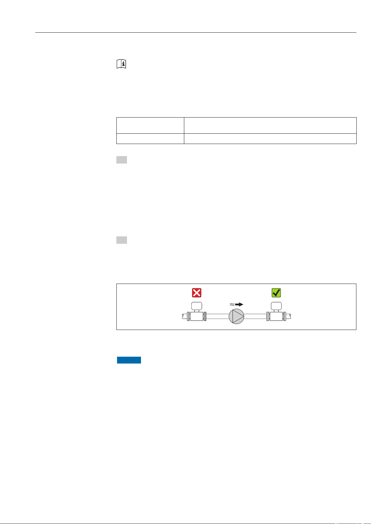
Ensure the system pressure is sufficiently high to prevent cavitation and outgassing.
‣
For this reason, the following mounting locations are recommended:
• At the lowest point in a vertical pipe
• Downstream from pumps (no danger of vacuum)
Heating
NOTICE
Electronics can overheat due to elevated ambient temperature!
Observe maximum permitted ambient temperature for the transmitter ( 19).
‣
Depending on the fluid temperature, take the device orientation requirements into
‣
account .
Heating options
If a fluid requires that no heat loss should occur at the sensor, users can avail of the
following heating options:
• Electrical heating, e.g. with electric band heaters
• Via pipes carrying hot water or steam
• Via heating jackets
A0015594
Endress+Hauser 19
Page 20
Installation Proline Promass I 100 Modbus RS485
3…5 × DN
PT TT
4…8 × DN
Using an electrical trace heating system
If heating is regulated via phase angle control or pulse packages, magnetic fields can affect
the measured values (= for values that are greater than the values approved by the EN
standard (sine 30 A/m)).
For this reason, the sensor must be magnetically shielded: the housing can be shielded
with tin plates or electric sheets without a privileged direction (e.g. V330-35A).
The sheet must have the following properties:
• Relative magnetic permeability µr ≥ 300
• Plate thickness d ≥ 0.35 mm (d ≥ 0.014 in)
Vibrations
The high oscillation frequency of the measuring tubes ensures that the correct operation of
the measuring system is not influenced by plant vibrations.
6.1.3 Special mounting instructions
Outlet run for peripheral device
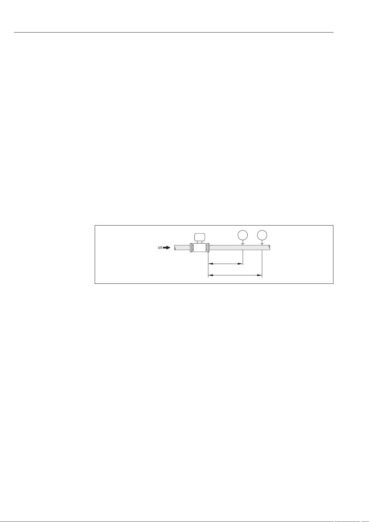
If a pressure and temperature measuring device are installed downstream from the
measuring device, make sure there is sufficient distance between the two devices.
A0016893
PT Pressure transmitter
TT Temperature transmitter
Guarantees complete drainability
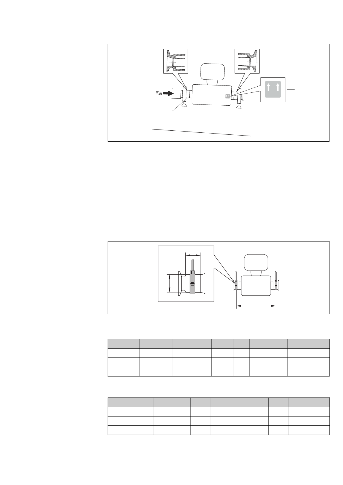
When the sensor is installed in a horizontal line, eccentric clamps can be used to ensure
complete drainability. When the system is pitched in a specific direction and at a specific
slope, gravity can be used to achieve complete drainability. The sensor must be mounted in
the correct position to ensure full drainability in the horizontal position. Markings on the
sensor show the correct mounting position to optimize drainability.
20 Endress+Hauser
Page 21
Proline Promass I 100 Modbus RS485 Installation
21 mm/m (¼ in/ft) ~2%
1
2
3
4
1
A
B
C
A0016585
6
1 Eccentric clamp connection
2 Line on the underside indicates the lowest point of the eccentric process connection.
3 "This side up" label indicates which side is up
4 Slope the device in accordance with the hygiene guidelines. Slope: approx. 2 % or 21mm/m (0.24 in/feet)
Securing with mounting clamp in the case of hygiene connections
It is not necessary to provide additional support for the sensor for operational performance
purposes. If, however, additional support is required for installation purposes, the
following dimensions must be observed.
Use mounting clamp with lining between clamp and measuring instrument.
A0016588
SI units
DN [mm] 8 15 15 FB 25 25 FB 40 40 FB 50 50 FB 80
A [mm] 373 409 539 539 668 668 780 780 1 152 1 152
B [mm] 20 20 30 30 28 28 35 35 57 57
C [mm] 40 40 44.5 44.5 60 60 80 80 90 90
US units
DN [in] 8 15 15 FB 25 25 FB 40 40 FB 50 50 FB 80
A [in] 14.69 16.1 21.22 21.22 26.3 26.3 30.71 30.71 45.35 45.35
B [in] 0.79 0.79 1.18 1.18 1.1 1.1 1.38 1.38 2.24 2.24
C [in] 1.57 1.57 1.75 1.75 2.36 2.36 3.15 3.15 3.54 3.54
Endress+Hauser 21
Page 22
Installation Proline Promass I 100 Modbus RS485
Zero point adjustment
All measuring devices are calibrated in accordance with state-of-the-art technology. The
zero point obtained in this way is printed on the nameplate of the measuring device.
Calibration takes place under reference conditions ( 81). Therefore, a zero point
adjustment in the field is generally not required! )
Experience shows that zero point adjustment is advisable only in special cases:
• To achieve maximum measuring accuracy even with very low flow rates
• Under extreme process or operating conditions, e.g.:
– high process temperature (> 50 °C (122 °F)
– high viscosity (> 100 cSt)
– high process pressure (> 20 bar (290 psi))
6.2 Mounting the measuring device
6.2.1 Required tools
For sensor
For flanges and other process connections: Corresponding mounting tools
6.2.2 Preparing the measuring device
1. Remove all remaining transport packaging.
2. Remove any protective covers or protective caps present from the sensor.
3. Remove stick-on label on the electronics compartment cover.
6.2.3 Mounting the measuring device
WARNING
Danger due to improper process sealing!
Ensure that the inside diameters of the gaskets are greater than or equal to that of the
‣
process connections and piping.
Ensure that the gaskets are clean and undamaged.
‣
Install the gaskets correctly.
‣
1. Ensure that the direction of the arrow on the nameplate of the sensor matches the
flow direction of the fluid.
2. Install the measuring device or turn the transmitter housing so that the cable entries
do not point upwards.
A0013964
22 Endress+Hauser
Page 23
Proline Promass I 100 Modbus RS485 Installation
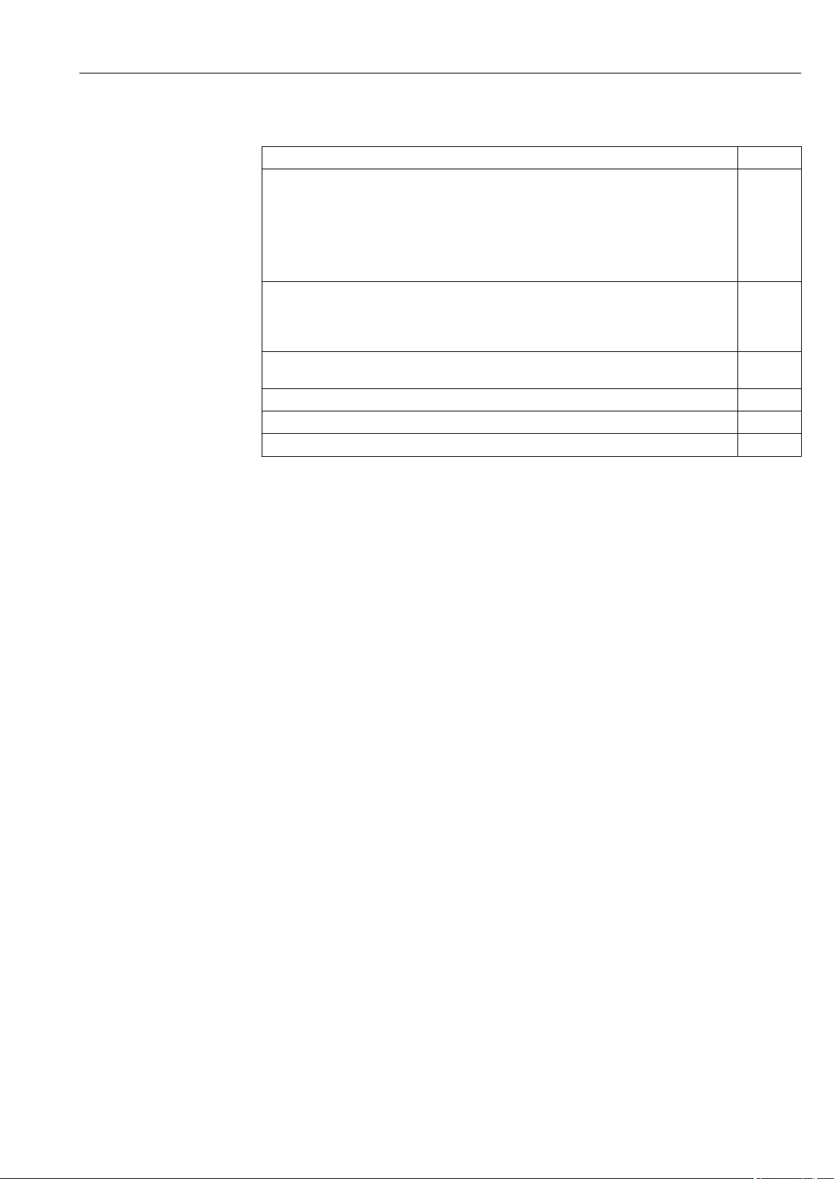
6.3 Post-installation check
Is the device damaged (visual inspection)?
Does the measuring device conform to the measuring point specifications?
For example:
• Process temperature ( 86)
• Process pressure (refer to the chapter on "Material load curves" of the "Technical Information"
document)
• Ambient temperature ( 19)
• Measuring range ( 76)
Has the correct orientation for the sensor been selected ?
• According to sensor type
• According to medium temperature
• According to medium properties (outgassing, with entrained solids)
Does the arrow on the sensor nameplate match the direction of flow of the fluid through the
piping ( 18)?
Are the measuring point identification and labeling correct (visual inspection)?
Is the device adequately protected from precipitation and direct sunlight?
Are the securing screw and securing clamp tightened securely?
Endress+Hauser 23
Page 24

Electrical connection Proline Promass I 100 Modbus RS485
7 Electrical connection
7.1 Connection conditions
7.1.1 Required tools
• For cable entries: Use corresponding tools
• For securing clamp (on aluminum housing): Allen screw 3 mm
• For securing screw (for stainless steel housing): open-ended wrench 8 mm
• Wire stripper
• When using stranded cables: Crimping tool for wire end ferrule
7.1.2 Requirements for connecting cable
The connecting cables provided by the customer must fulfill the following requirements.
Electrical safety
In accordance with applicable federal/national regulations.
Permitted temperature range
• –40 °C (–40 °F)...≥ 80 °C (176 °F)
• Minimum requirement: cable temperature range ≥ ambient temperature + 20 K
Power supply cable
Standard installation cable is sufficient.
Signal cable
Modbus RS485
The EIA/TIA-485 standard specifies two types of cable (A and B) for the bus line which
can be used for every transmission rate. Cable type A is recommended.
Cable type A
Characteristic impedance 135 to 165 Ωat a measuring frequency of 3 to 20 MHz
Cable capacitance < 30 pF/m
Wire cross-section
Cable type Twisted pairs
Loop resistance ≤ 110 Ω/km
Signal damping Max. 9 dB over the entire length of the cable cross-section
Shielding Copper braided shielding or braided shielding with foil shield. When grounding
> 0.34 mm2 (22 AWG)
the cable shield, observe the grounding concept of the plant.
Connecting cable between Safety Barrier Promass 100 and measuring device
Cable type Shielded twisted-pair cable with 2x2 wires. When grounding the cable shield,
observe the grounding concept of the plant.
Maximum cable resistance 2.5 Ω, one side
24 Endress+Hauser
Page 25
Proline Promass I 100 Modbus RS485 Electrical connection
Comply with the maximum cable resistance specifications to ensure the operational
‣
reliability of the measuring device.
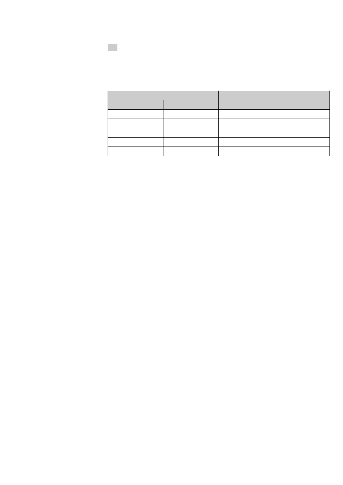
The maximum cable length for individual wire cross-sections is specified in the table
below. Observe the maximum capacitance and inductance per unit length of the cable and
the connection values in the Ex documentation ( 93).
Wire cross-section Maximum cable length
[mm2] [AWG] [m] [ft]
0.5 20 70 230
0.75 18 100 328
1.0 17 100 328
1.5 16 200 656
2.5 14 300 984
Cable diameter
• Cable glands supplied:
M20 × 1.5 with cable 6 to 12 mm (0.24 to 0.47 in)
• Spring terminals:
wire cross-sections 0.5 to 2.5 mm2 (20 to 14 AWG)
• With Safety Barrier Promass 100:
Plug-in screw terminals for wire cross-sections 0.5 to 2.5 mm2 (20 to 14 AWG)
Endress+Hauser 25
Page 26
Electrical connection Proline Promass I 100 Modbus RS485
L
L
26
27AB
1
2
+
_
1
2
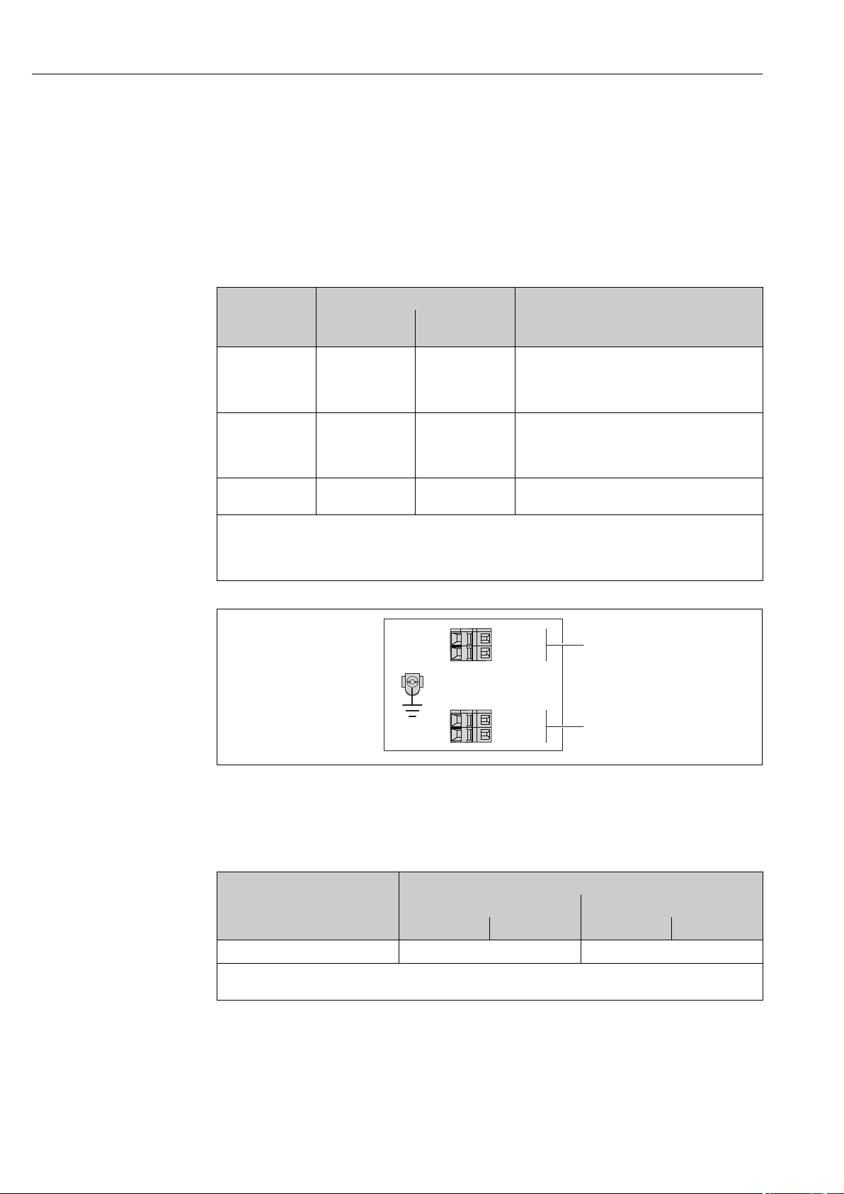
7.1.3 Terminal assignment
Transmitter
Connection version Modbus RS485, for use in non-hazardous areas and Zone 2/Div. 2
Order code for "Output", option M
Depending on the housing version, the transmitters can be ordered with terminals or
device plugs.
Order code for
"Housing"
Options
A, B
Options
A, B
Options
A, B, C
Order code for "Housing":
• Option A: compact, coated alu
• Option B: compact hygienic, stainless
• Option C: ultra compact hygienic, stainless, M12 device plug
Connection methods available
Output
Terminals Terminals • Option A: coupling M20x1
Device plug
( 28)
Device plug
( 28)
Power
supply
Terminals • Option L: plug M12x1 + thread NPT ½"
Device plug
( 28)
Possible options for order code
"Electrical connection"
• Option B: thread M20x1
• Option C: thread G ½"
• Option D: thread NPT ½"
• Option N: plug M12x1 + coupling M20
• Option P: plug M12x1 + thread G ½"
• Option U: plug M12x1 + thread M20
Option Q: 2 x plug M12x1
A0019528
7 Modbus RS485 terminal assignment, connection version for use in non-hazardous areas and Zone 2/Div.
2
1 Power supply: DC 24 V
2 Output: Modbus RS485
Terminal number
Order code for
"Output"
Option M 24 DC V Modbus RS485
Order code for "Output":
Option M: Modbus RS485, for use in non-hazardous areas and Zone 2/Div. 2
Power supply Output
2 (L-) 1 (L+) 27 (B) 26 (A)
Connection version Modbus RS485, for use in intrinsically safe areas (connection via Safety
Barrier Promass 100)
26 Endress+Hauser
Order code for "Output", option M: Modbus R485, for use in intrinsically safe areas
(connection via Safety Barrier Promass 100)
Page 27
Proline Promass I 100 Modbus RS485 Electrical connection
L
L
62
72AB
10
20
+
_
1
2
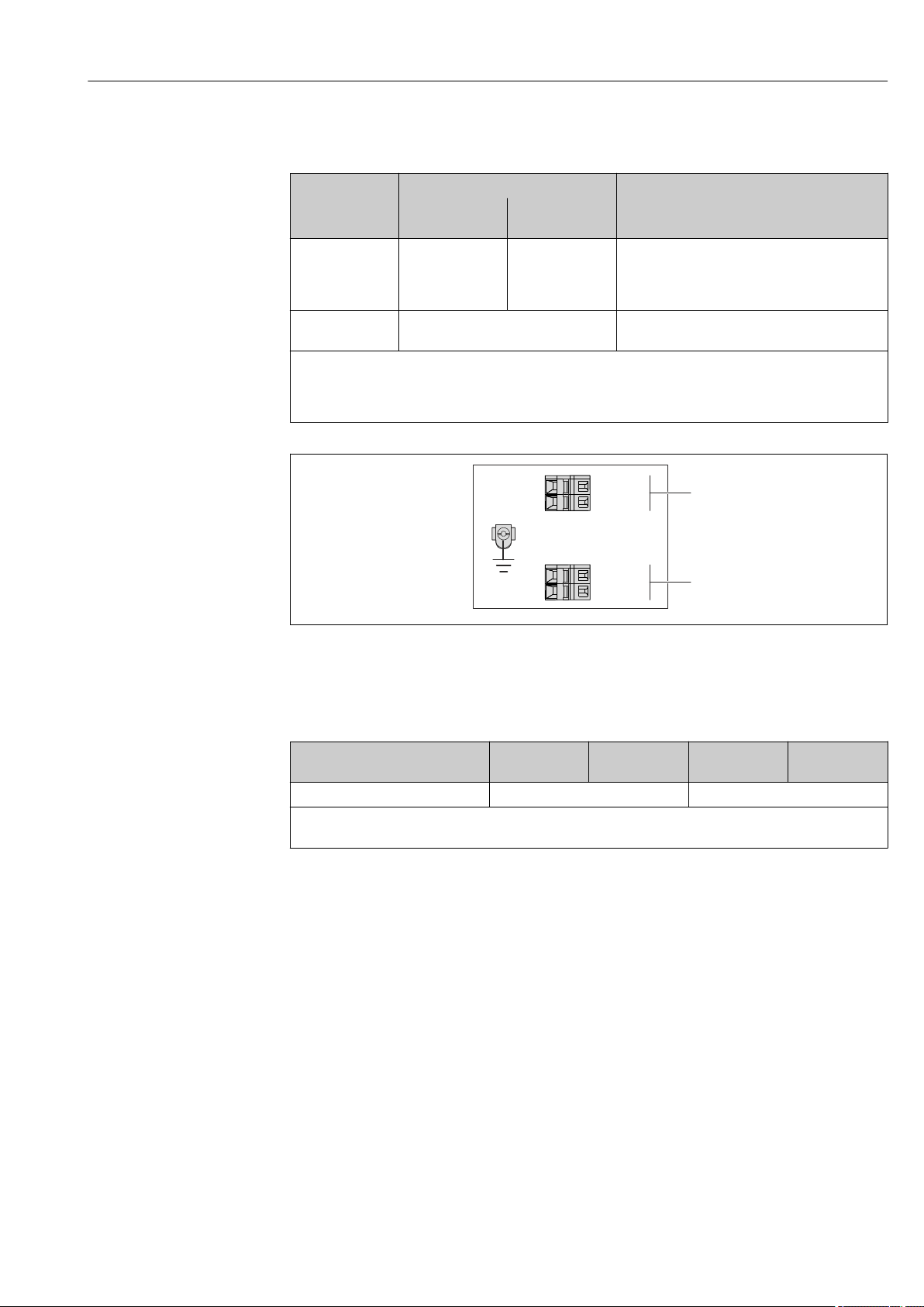
Depending on the housing version, the transmitters can be ordered with terminals or
device plugs.
Order code for
"Housing"
Options
A, B
A, B, C Device plug
Order code for "Housing":
• Option A: compact, coated alu
• Option B: compact hygienic, stainless
• Option C: ultra compact hygienic, stainless, M12 device plug
8 Modbus RS485 terminal assignment, connection version for use in intrinsically safe areas (connection via
Safety Barrier Promass 100)
1 Intrinsically safe power supply
2 Output: Modbus RS485
Connection methods available
Output
Terminals Terminals • Option A: coupling M20x1
( 28)
Power
supply
Possible options for order code
"Electrical connection"
• Option B: thread M20x1
• Option C: thread G ½"
• Option D: thread NPT ½"
Option I: plug M12x1
A0017053
Order code for
"Output"
Option M Intrinsically safe supply voltage Modbus RS485 intrinsically safe
Order code for "Output":
Option M: Modbus RS485, for use in intrinsically safe areas (connection via Safety Barrier Promass 100)
20 (L-) 10 (L+) 72 (B) 62 (A)
Endress+Hauser 27
Page 28
Electrical connection Proline Promass I 100 Modbus RS485
A
Safe area
1
L+2L
27
26
A B
Power
supply
24V
DC
Modbus
RS485
10207262
L+L A B
Power
supply
Modbus
RS485
Hazardous area
Safety Barrier
Promass 100
Power
Communication
Lift panel for
bus termination
1
2
A
1
2
4
3
5
1
2
4
3
5
Safety Barrier Promass 100
A0016922
9 Safety Barrier Promass 100 with terminals
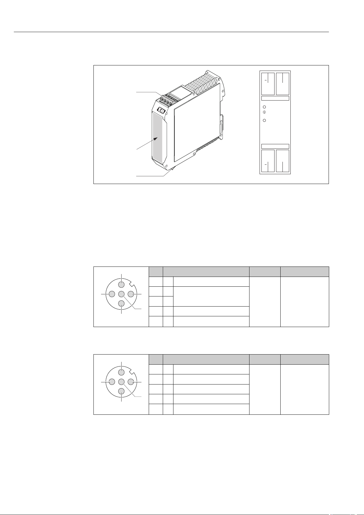
1 Non-hazardous area and Zone 2/Div. 2
2 Intrinsically safe area
7.1.4 Pin assignment, device plug
Modbus RS485
Modbus RS485 intrinsically safe with supply voltage (on the device side)
Pin Assignment Coding Plug/socket
1 L+ Supply voltage, intrinsically safe A Plug
2 A
3 B
4 L- Supply voltage, intrinsically safe
A0016809
5 Grounding/shielding
Supply voltage for Modbus RS485, non-hazardous area and Zone 2/Div. 2 (on the device
side)
Pin Assignment Coding Plug/socket
1 L+ DC24 V A Plug
2
3
4 L- DC24 V
A0016809
28 Endress+Hauser
5 Grounding/shielding
Modbus RS485 intrinsically safe
Page 29

Proline Promass I 100 Modbus RS485 Electrical connection
3
2
4
1
5
Modbus RS485, non-hazardous areas and zone 2/Div. 2 (on the device side)
Pin Assignment Coding Plug/socket
1 B Socket
2 A Modbus RS485
3
4 B Modbus RS485
A0016811
5 Grounding/shielding
7.1.5 Shielding and grounding
The shielding and grounding concept requires compliance with the following:
• Electromagnetic compatibility (EMC)
• Explosion protection
• Personal protection equipment
• National installation regulations and guidelines
• Observe cable specification ( 24).
• Keep the stripped and twisted lengths of cable shield to the ground terminal as short as
possible.
• Seamless cable shielding.
Grounding of the cable shield
To comply with EMC requirements:
• Ensure the cable shield is grounded to the potential matching line at multiple points.
• Connect every local ground terminal to the potential matching line.
NOTICE
In systems without potential matching, the multiple grounding of the cable shield
causes mains frequency equalizing currents!
Damage to the bus cable shield.
Only ground the bus cable shield to either the local ground or the protective ground at
‣
one end.
7.1.6 Preparing the measuring device
1. Remove dummy plug if present.
2. NOTICE! Insufficient sealing of the housing! Operational reliability of the measuring
device could be compromised. Use suitable cable glands corresponding to the degree
of protection.
If measuring device is delivered without cable glands:
Provide suitable cable gland for corresponding connecting cable ( 24).
3. If measuring device is delivered with cable glands:
Observe cable specification ( 24).
7.2 Connecting the measuring device
NOTICE
Limitation of electrical safety due to incorrect connection!
Have electrical connection work carried out by correspondingly trained specialists only.
‣
Observe applicable federal/national installation codes and regulations.
‣
Comply with local workplace safety regulations.
‣
For use in potentially explosive atmospheres, observe the information in the device-
‣
specific Ex documentation.
Endress+Hauser 29
Page 30
Electrical connection Proline Promass I 100 Modbus RS485
1 2 1 2 3 4
A B C
10 (0.4)
mm (in)
1 2
3
2
1
2
1
2
3
8 mm
3 mm
8 mm
7.2.1 Connecting the transmitter
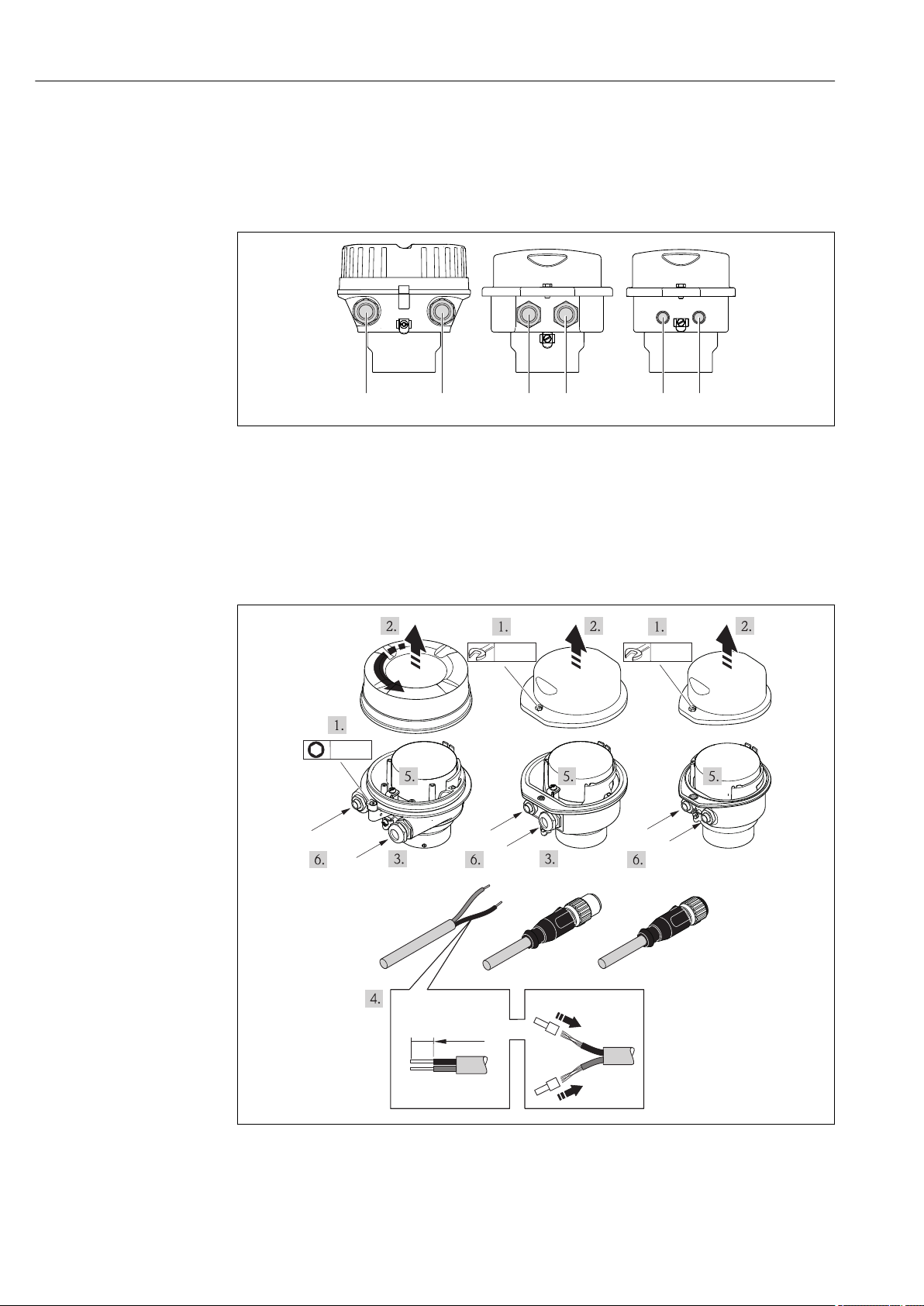
The connection of the transmitter depends on the following order codes:
• Housing version: compact or ultracompact
• Connection version: device plug or terminals
A0016924
10 Device versions and connection versions
A Housing version: compact, aluminum coated
B Housing version: compact hygienic, stainless
1 Cable entry or device plug for signal transmission
2 Cable entry or device plug for supply voltage
C Housing version: ultra-compact hygienic, stainless, device plug M12
3 Device plug for signal transmission
4 Device plug for supply voltage
11 Device versions with connection examples
1 Cable
2 Device plug for signal transmission
3 Device plug for supply voltage
30 Endress+Hauser
A0017844
Page 31
Proline Promass I 100 Modbus RS485 Electrical connection
21
A
B
A
B
3
L+
L-
A
B
L+
L-
L- L+
A
B
5 6 7
8
4
For device version with device plug: only pay attention to Step 6.
1. Depending on the housing version, loosen the securing clamp or fixing screw of the
housing cover.
2. Depending on the housing version, unscrew or open the housing cover.
3. Push the cable through the cable entry . To ensure tight sealing, do not remove the
sealing ring from the cable entry.
4. Strip the cable and cable ends. In the case of stranded cables, also fit ferrules.
5. Connect the cable in accordance with the terminal assignment or the device plug pin
assignment ( 28).
6. Depending on the device version: tighten the cable glands or plug in the device plug
and tighten ( 28).
7. Enable the terminating resistor if applicable ( 32).
8. NOTICE! Housing degree of protection voided due to insufficient sealing of the
housing. Screw in the screw without using any lubricant. The threads on the cover are
coated with a dry lubricant.
Reverse the removal procedure to reassemble the transmitter.
7.2.2 Connecting the Safety Barrier Promass 100
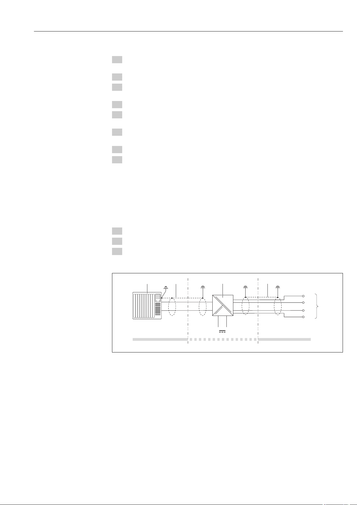
In the case of the device version with Modbus RS485 intrinsically safe, the transmitter
must be connected to the Safety Barrier Promass 100.
1. Strip the cable ends. In the case of stranded cables, also fit ferrules.
2. Connect the cable in accordance with the terminal assignment ( 28).
3. Where applicable, enable the terminating resistor in the Safety Barrier Promass 100
( 32).
12 Electrical connection between the transmitter and Safety Barrier Promass 100
1 Control system (e.g. PLC)
2 Observe cable specification
3 Safety Barrier Promass 100: terminal assignment (→ 28)
4 Observe cable specification (→ 24)
5 Non-hazardous area
6 Non-hazardous area and Zone 2/Div. 2
7 Intrinsically safe area
8 Transmitter: terminal assignment
A0016804
Endress+Hauser 31
Page 32
Electrical connection Proline Promass I 100 Modbus RS485
2 - Not used
1 - Write protection
4 - Bus termination
3 - Not used
OFFON
26
27AB
220 W
26
27AB
220 W
ON
1 2
A
A
7.3 Hardware settings
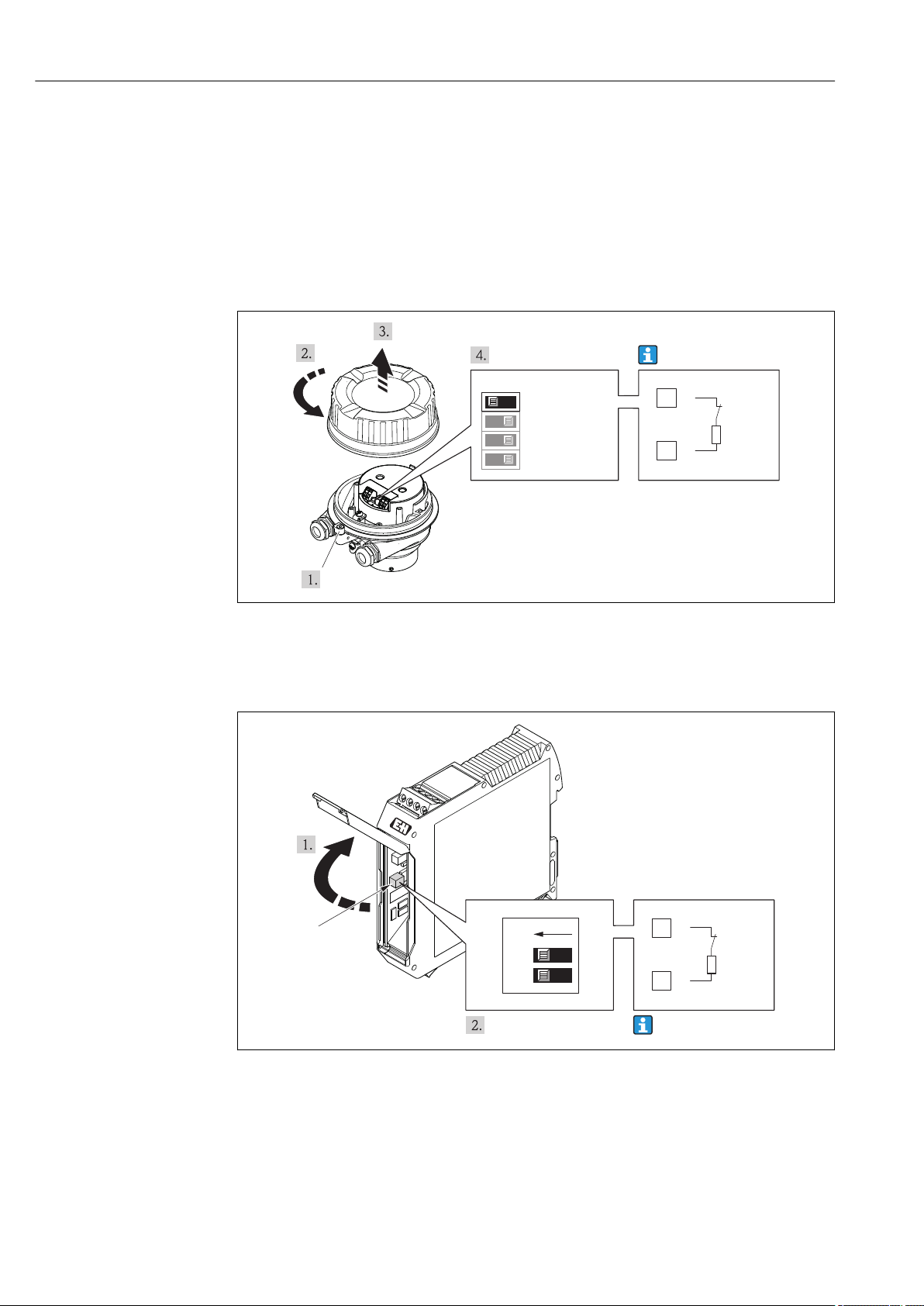
7.3.1 Enabling the terminating resistor
To avoid incorrect communication transmission caused by impedance mismatch, connect
the Modbus RS485 cable correctly to the start and end of the bus segment.
If the transmitter is used in the non-hazardous area or Zone 2/Div. 2
13 Terminating resistor can be enabled via DIP switch on the main electronics module
If the transmitter is used in the intrinsically safe area
14 Terminating resistor can be enabled via DIP switch in the Safety Barrier Promass 100
7.4 Ensuring the degree of protection
The measuring device fulfills all the requirements for the IP66/67 degree of protection,
Type 4X enclosure.
32 Endress+Hauser
A0017610
A0017791
Page 33
Proline Promass I 100 Modbus RS485 Electrical connection
To guarantee IP66/67 degree of protection, Type 4X enclosure, carry out the following
steps after the electrical connection:
1. Check that the housing seals are clean and fitted correctly. Dry, clean or replace the
seals if necessary.
2. Tighten all housing screws and screw covers.
3. Firmly tighten the cable glands.
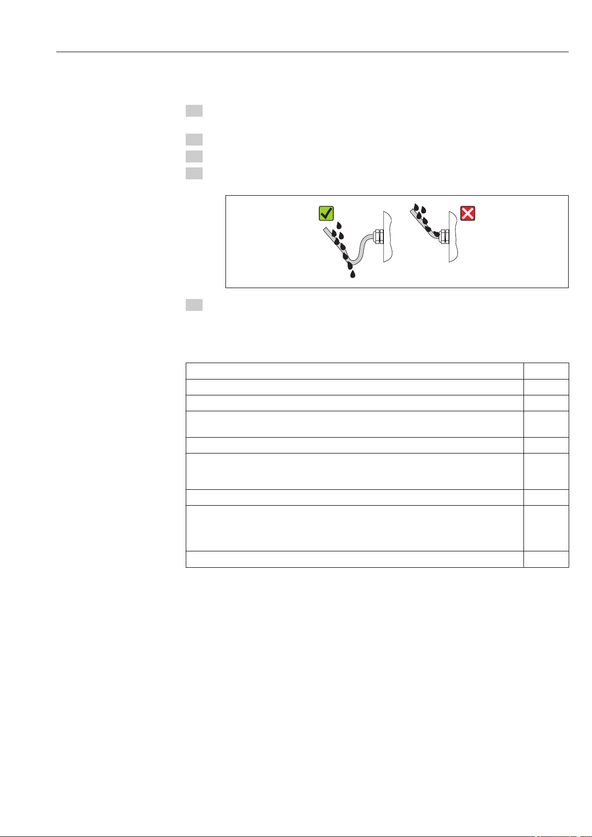
4. To ensure that moisture does not enter the cable entry, route the cable so that it
loops down before the cable entry ("water trap").
A0013960
5. Insert dummy plugs into unused cable entries.
7.5 Post-connection check
Are cables or the device undamaged (visual inspection)?
Do the cables comply with the requirements ( 24)?
Do the cables have adequate strain relief?
Are all the cable glands installed, firmly tightened and leak-tight? Cable run with "water trap"
( 32) ?
Depending on the device version: are all the device plugs firmly tightened ( 30)?
• Does the supply voltage match the specifications on the transmitter nameplate ( 80)?
• For device version with Modbus RS485 intrinsically safe: does the supply voltage match the
specifications on the nameplate of the Safety Barrier Promass 100 ( 80)?
Is the terminal assignment or the pin assignment of the device plug ( 28) correct?
• If supply voltage is present, is the power LED on the electronics module of the transmitter lit
green ( 10)?
• For device version with Modbus RS485 intrinsically safe, if supply voltage is present, is the
power LED on the Safety Barrier Promass 100 lit ( 10)?
Depending on the device version, is the securing clamp or fixing screw firmly tightened?
Endress+Hauser 33
Page 34
Operation options Proline Promass I 100 Modbus RS485
1
2
8 Operation options
8.1 Overview of operation options
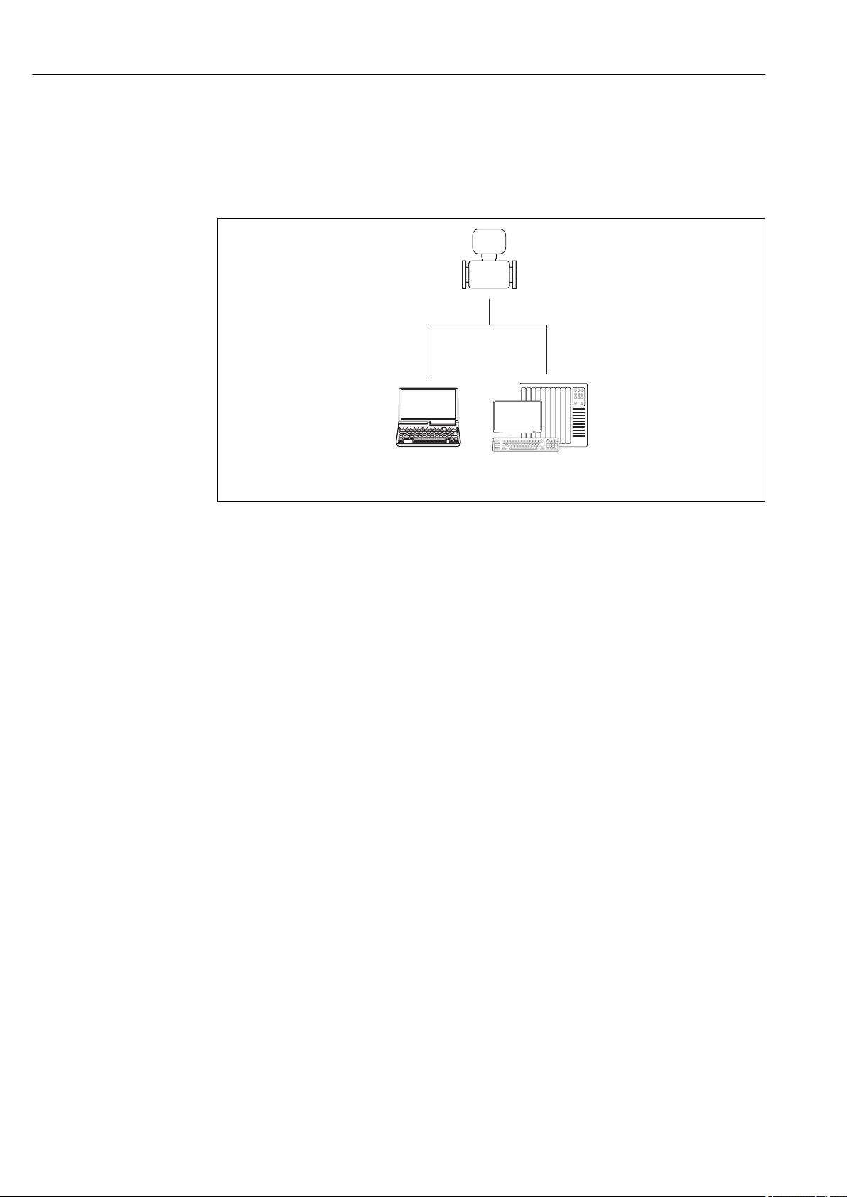
1 Computer with "FieldCare" operating tool via Commubox FXA291 and service interface (CDI)
2 Control system (e.g. PLC)
A0017760
34 Endress+Hauser
Page 35
Proline Promass I 100 Modbus RS485 Operation options
Expert
System
Sensor
Communication
Application
Diagnostics
Locking status
Access status tooling
Operating menu for experts
Display/operat.
Locking status
Operation
Setup
Advanced setup
Enter access code
Parameter 1
Parameter n
Submenu 1
Submenu n
Diagnostics
Parameter 1
Parameter n
Submenu 1
Submenu n
Operating menu for operators and maintenances
Operator
Maintenance
Task-oriented
Function-oriented
Expert
Enter access code
Submenu 1
Submenu n
Submenu 2
8.2 Structure and function of the operating menu
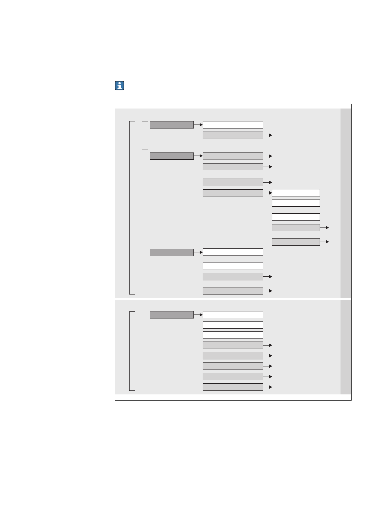
8.2.1 Structure of the operating menu
For an overview of the operating menu with menus and parameters ( 94)
15 Taking the example of the "FieldCare" operating tool
A0016726-EN
Endress+Hauser 35
Page 36

Operation options Proline Promass I 100 Modbus RS485
8.2.2 Operating philosophy
The individual parts of the operating menu are assigned to certain user roles. Each user
role corresponds to typical tasks within the device lifecycle.
Menu User role and tasks Content/meaning
Display/operat. task-oriented Role "Operator", "Maintenance"
Tasks during operation:
Reading measured values
Setup "Maintenance" role
Commissioning:
• Configuration of the measurement
• Configuration of the communication interface
Diagnostics "Maintenance" role
Fault elimination:
• Diagnostics and elimination of process and
device errors
• Measured value simulation
Resetting and controlling totalizers
Submenus for fast commissioning:
• Setting the individual system units
• Defining the medium
• Configuration of the digital communication interface
• Configuring the low flow cut off
• Configuring the monitoring of partial and empty pipe
detection
"Advanced setup" submenu:
• For more customized configuration of the
measurement (adaptation to special measuring
conditions)
• Configuration of totalizers
Contains all parameters for error detection and
analyzing process and device errors:
• "Diagnostic list" submenu
Contains up to 5 currently pending diagnostic
messages.
• "Event logbook" submenu
Contains 20 event messages that have occurred.
• "Device information" submenu
Contains information for identifying the device.
• "Measured values" submenu
Contains all current measured values.
• "Simulation" submenu
Is used to simulate measured values or output values.
• "Device reset" submenu
Resets the device configuration to certain settings
Expert function-oriented Tasks that require detailed knowledge of the
function of the device:
• Commissioning measurements under difficult
conditions
• Optimal adaptation of the measurement to
difficult conditions
• Detailed configuration of the communication
interface
• Error diagnostics in difficult cases
Contains all the parameters of the device and makes it
possible to access these parameters directly using an
access code. The structure of this menu is based on the
function blocks of the device:
• "System" submenu
Contains all higher-order device parameters that do
not pertain either to measurement or the measured
value communication.
• "Sensor" submenu
Contains all parameters for configuring the
measurement.
• "Communication" submenu
Contains all parameters for configuring the digital
communication interface.
• "Application" submenu
Contains all parameters for configuring the functions
that go beyond the actual measurement (e.g.
totalizer).
• "Diagnostics" submenu
Contains all parameters for error detection and
analyzing process and device errors and for device
simulation.
36 Endress+Hauser
Page 37
Proline Promass I 100 Modbus RS485 Operation options
1
2
3
8.3 Access to the operating menu via the operating tool
8.3.1 Connecting the operating tool
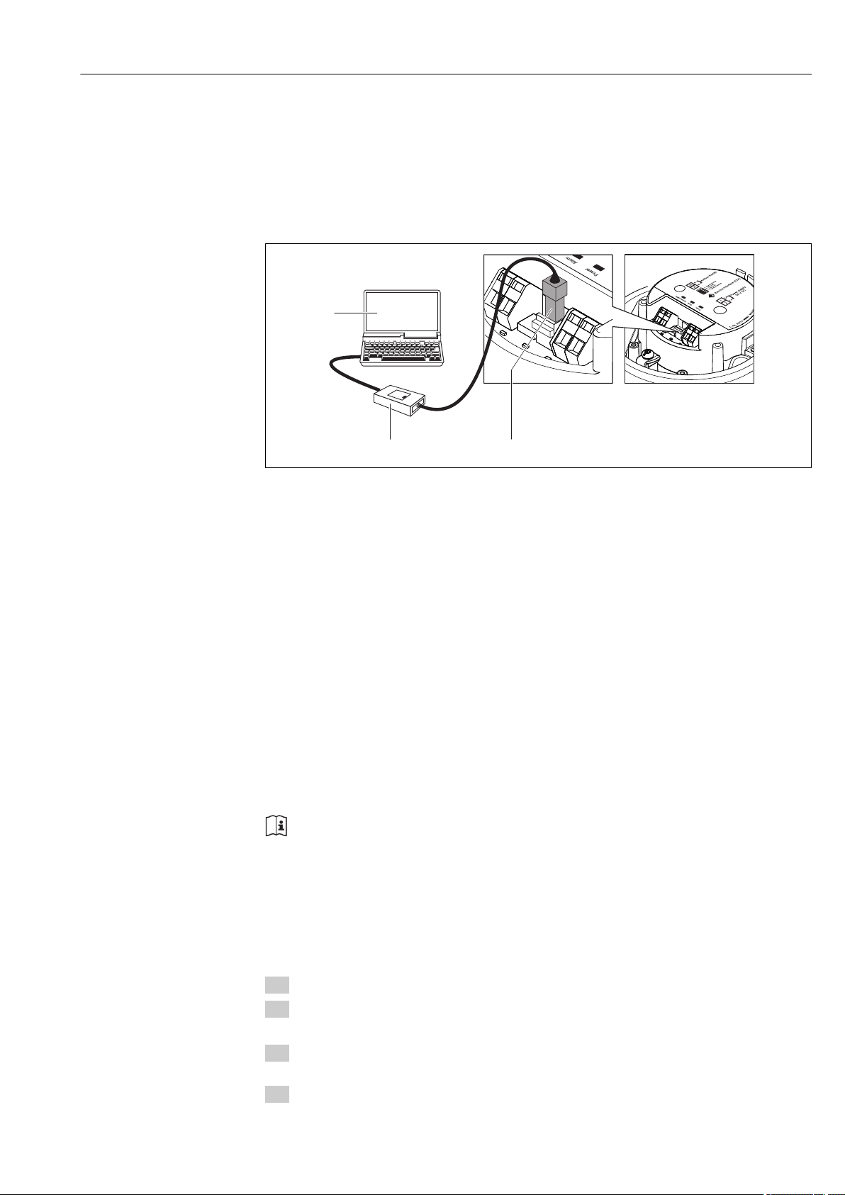
Via service interface (CDI)
A0016925
1 Service interface (CDI) of the measuring device
2 Commubox FXA291
3 Computer with "FieldCare" operating tool with COM DTM "CDI Communication FXA291"
8.3.2 FieldCare
Function scope
FDT-based plant asset management tool from Endress+Hauser. It can configure all smart
field units in a system and helps you manage them. By using the status information, it is
also a simple but effective way of checking their status and condition.
Access takes place via:
Service interface CDI ( 37)
Typical functions:
• Configuring parameters of transmitters
• Loading and saving device data (upload/download)
• Documentation of the measuring point
• Visualization of the measured value memory (line recorder) and event logbook
For details, see Operating Instructions BA00027S and BA00059S
Source for device description files
See data ( 39)
Establishing a connection
Via service interface (CDI)
1. Start FieldCare and launch the project.
2. In the network: Add a device.
The Add device window opens.
3. Select the CDI Communication FXA291 option from the list and press OK to
confirm.
4. Right-click CDI Communication FXA291 and select the Add device option in the
context menu that opens.
Endress+Hauser 37
Page 38
Operation options Proline Promass I 100 Modbus RS485
5. Select the desired device from the list and press OK to confirm.
6. Establish the online connection to the device.
For details, see Operating Instructions BA00027S and BA00059S
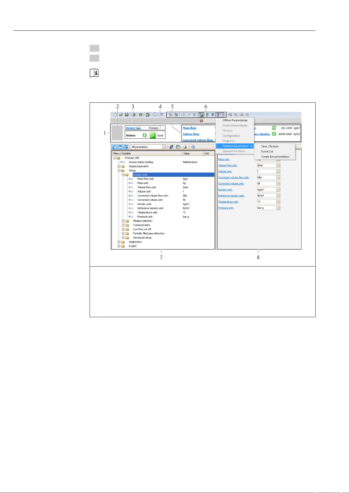
User interface
1
Header
2
Picture of device
3
Device tag (→ 57)
4
Status area with status signal (→ 63)
5
Display area for current measured values (→ 57)
6
Event list with additional functions such as save/load, events list and document creation
7
Navigation area with operating menu structure
8
Working area
A0017402-EN
38 Endress+Hauser
Page 39
Proline Promass I 100 Modbus RS485 System integration
9 System integration
9.1 Overview of device description files
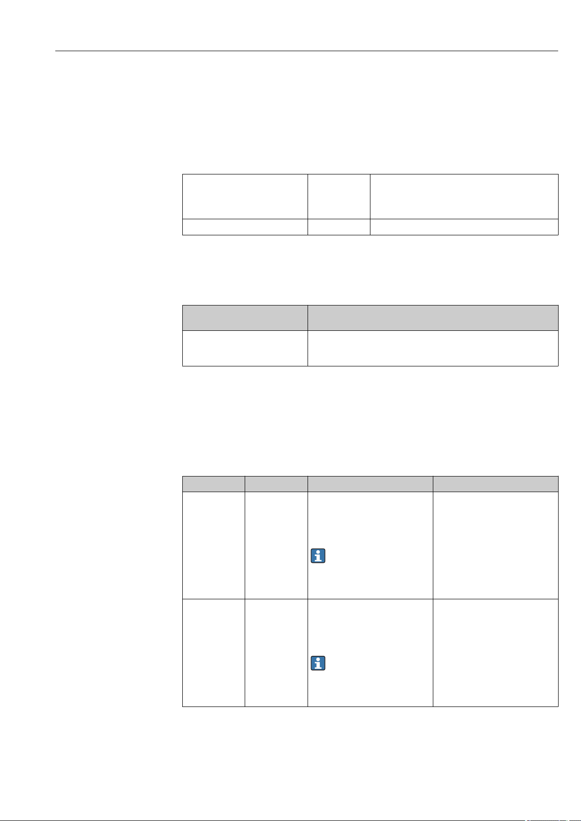
9.1.1 Current version data for the device
Firmware version 01.02.00 • On the title page of the Operating instructions
• On transmitter nameplate ( 12)
• Parameter firmware version
Diagnostics Device info Firmware version
Release date of firmware version 04.2013 ---
9.1.2 Operating tools
The suitable device description file for the operating tool is listed in the table below, along
with information on where the file can be acquired.
Operating tool via service
interface (CDI)
FieldCare • www.endress.com Download Area
Sources for obtaining device descriptions
• CD–ROM (contact Endress+Hauser)
• DVD (contact Endress+Hauser)
9.2 Modbus RS485 information
9.2.1 Function codes
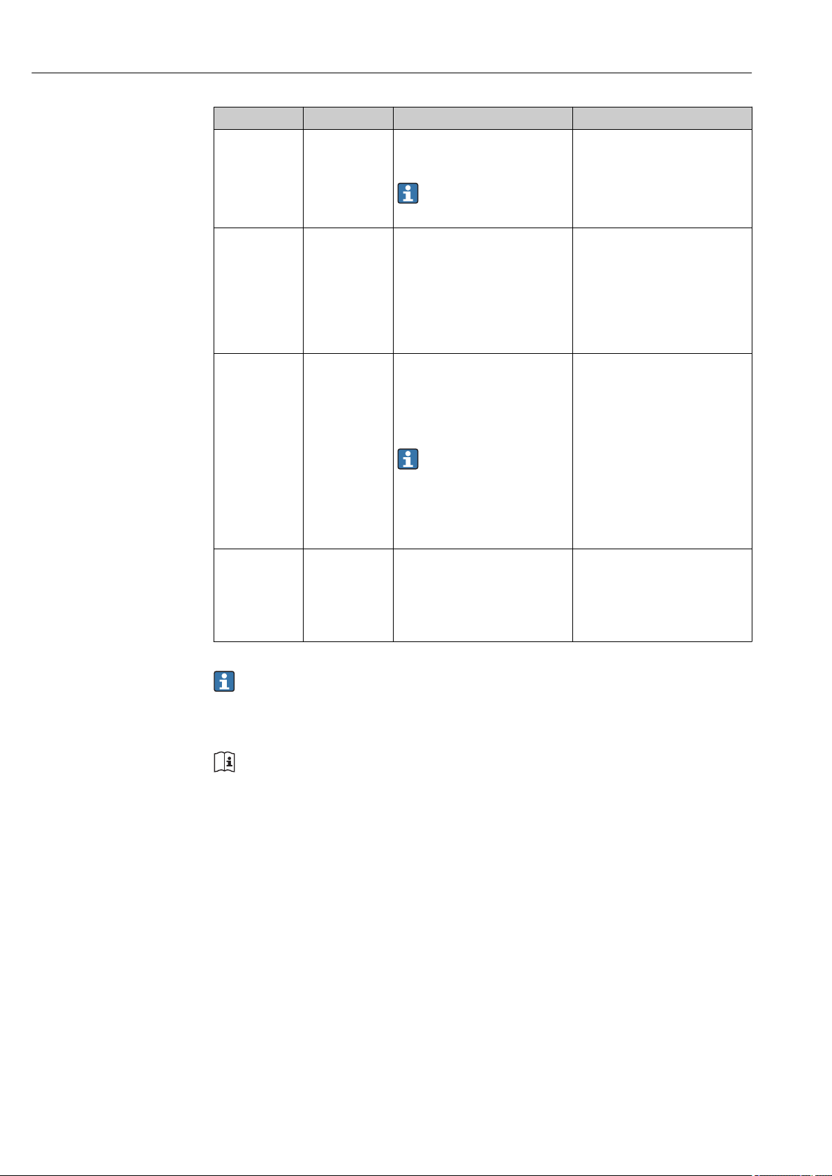
Function codes are used to define which read or write action is carried out via the Modbus
protocol. The measuring device supports the following function codes:
Code Name Description Application
03 Read holding
register
04 Read input
register
Master reads one or more Modbus
registers from the device.
A maximum of 125 consecutive
registers can be read with 1
telegram: 1 register = 2 bytes
The measuring device does
not make a distinction
between function codes 03
and 04; these codes therefore
yield the same result.
Master reads one or more Modbus
registers from the device.
A maximum of 125 consecutive
registers can be read with 1
telegram: 1 register = 2 bytes
The measuring device does
not make a distinction
between function codes 03
and 04; these codes therefore
yield the same result.
Read device parameters with read
and write access
Example:
Read mass flow
Read device parameters with read
access
Example:
Read totalizer value
Endress+Hauser 39
Page 40
System integration Proline Promass I 100 Modbus RS485
Code Name Description Application
06 Write single
registers
08 Diagnostics Master checks the communication
16 Write multiple
registers
23 Read/Write
multiple
registers
Master writes a new value to one
Modbus register of the measuring
device.
Use function code 16 to write
multiple registers with just 1
telegram.
connection to the measuring device.
The following "Diagnostics codes"
are supported:
• Sub-function 00 = Return query
data (loopback test)
• Sub-function 02 = Return
diagnostics register
Master writes a new value to
multiple Modbus registers of the
device.
A maximum of 120 consecutive
registers can be written with 1
telegram.
If the required device
parameters are not available
as a group, yet must
nevertheless be addressed
with a single telegram, use
Modbus data map
( 40)
Master reads and writes a
maximum of 118 Modbus registers
of the measuring device
simultaneously with 1 telegram.
Write access is executed before
read access.
Write only 1 device parameter
Example: reset totalizer
Write multiple device parameters
Example:
• Mass flow unit
• Mass unit
Write and read multiple device
parameters
Example:
• Read mass flow
• Reset totalizer
Broadcast messages are only allowed with function codes 06, 16 and 23.
9.2.2 Register information
For an overview on Modbus-specific information of the individual device parameters,
please refer to the additional document on Modbus RS485 register information
( 93)
9.2.3 Response time
Response time of the measuring device to the request telegram of the Modbus master:
typically 3 to 5 ms
9.2.4 Modbus data map
Function of the Modbus data map
The device offers a special memory area, the Modbus data map (for a maximum of 16
device parameters), to allow users to call up multiple device parameters via Modbus RS485
and not only individual device parameters or a group of consecutive device parameters.
Grouping of device parameters is flexible and the Modbus master can read or write to the
entire data block simultaneously with a single request telegram.
40 Endress+Hauser
Page 41
Proline Promass I 100 Modbus RS485 System integration
Structure of the Modbus data map
The Modbus data map consists of two data sets:
• Scan list: Configuration area
The device parameters to be grouped are defined in a list in that their Modbus RS485
register addresses are entered in the list.
• Data area
The measuring device reads out the register addresses entered in the scan list cyclically
and writes the associated device data (values) to the data area.
For an overview of device parameters with their individual Modbus register address,
please refer to the additional document on Modbus RS485 register information
( 93)
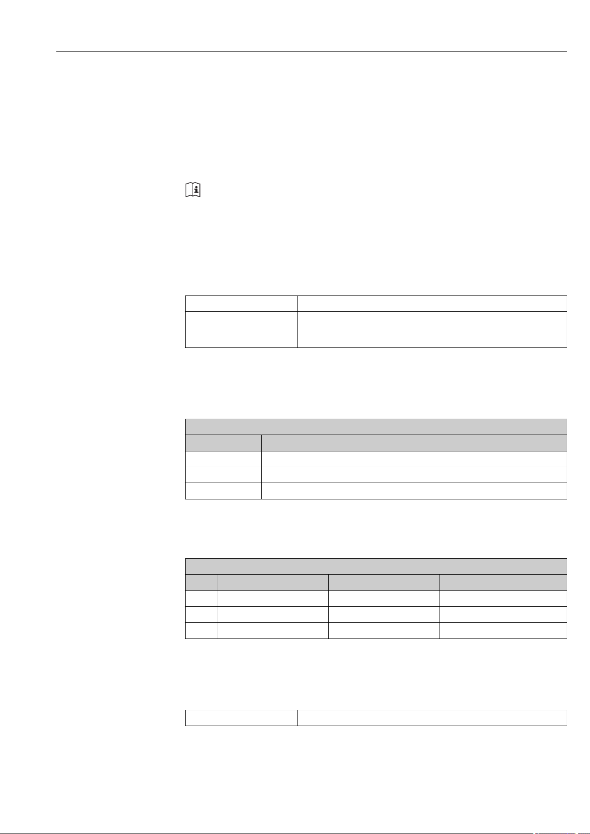
Scan list configuration
For configuration, the Modbus RS485 register addresses of the device parameters to be
grouped must be entered in the scan list. Please note the following basic requirements of
the scan list:
Max. entries 16 device parameters
Supported device parameters Only parameters with the following characteristics are supported:
• Access type: read or write access
• Data type: float or integer
Configuring the scan list via FieldCare
Carried out using the operating menu of the measuring device:
Expert Communication Modbus data map Scan list register 0 -15
Scan list
No. Configuration register
0 Scan list register 0
... ...
15 Scan list register 15
Configuring the scan list via Modbus RS485
Carried out using register addresses 5001 - 5016
Scan list
No. Modbus RS485 register Data type Configuration register
0 5001 Integer Scan list register 0
... ... Integer ...
15 5016 Integer Scan list register 15
Reading out data via Modbus RS485
The Modbus master accesses the data area of the Modbus data map to read out the current
values of the device parameters defined in the scan list.
Master access to data area Via register addresses 5051-5081
Endress+Hauser 41
Page 42

System integration Proline Promass I 100 Modbus RS485
Data area
Device parameter value Modbus RS485
register
Value of scan list register 0 5051 Integer/float Read/write
Value of scan list register 1 5053 Integer/float Read/write
Value of scan list register ... ... ... ...
Value of scan list register 15 5081 Integer/float Read/write
* Data type depends on the device parameters entered in the scan list.
** Data access depends on the device parameters entered in the scan list. If the device parameter entered
supports read and write access, the parameter can also be accessed via the data area.
Data type* Access**
42 Endress+Hauser
Page 43
Proline Promass I 100 Modbus RS485 Commissioning
10 Commissioning
10.1 Function check
Before commissioning the device, make sure that the post-installation and postconnection checks have been performed.
• "Post-mounting check" checklist ( 23)
• "Post-connection check" checklist ( 33)
10.2 Establishing a connection via FieldCare
• For FieldCare connection ( 37)
• For establishing a connection via FieldCare ( 37)
• For FieldCare user interface ( 38)
10.3 Configuring the measuring device
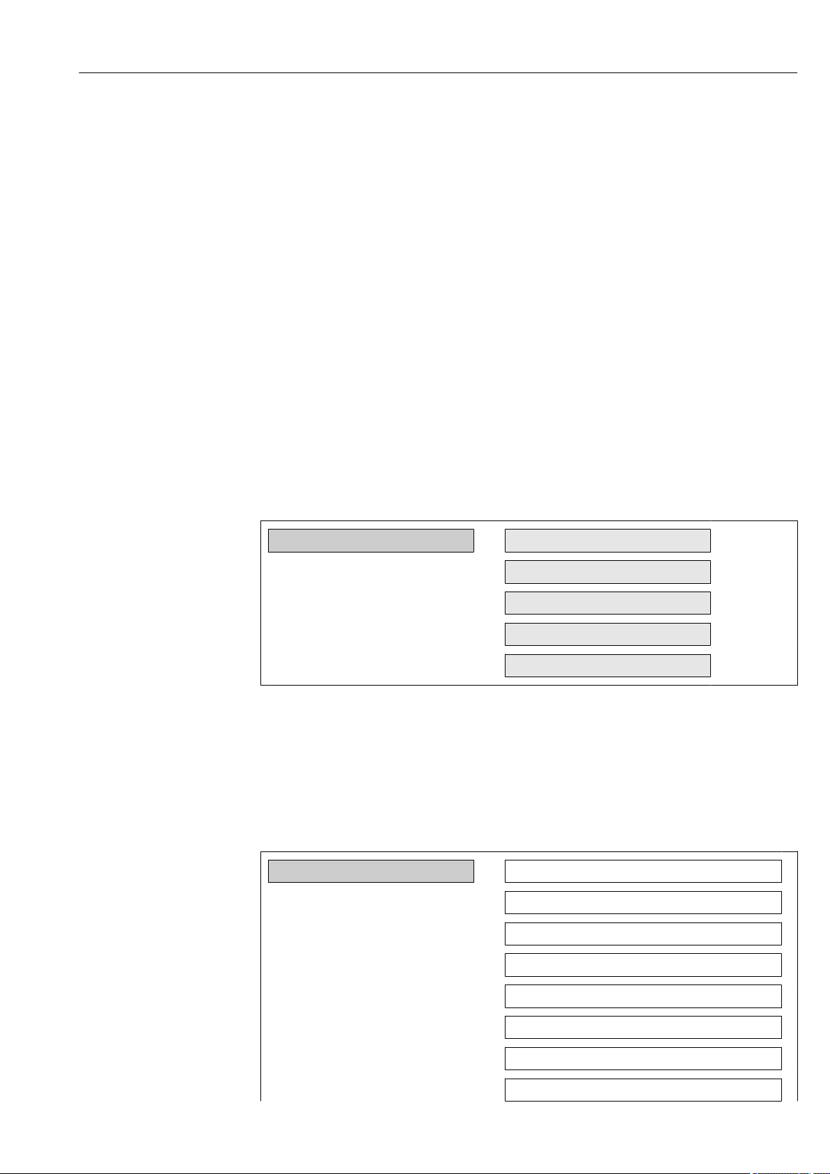
The Setup menu with its submenus contains all parameters needed for standard
operation.
Structure of the "Setup" menu
Setup
System units
Select medium
Communication
Low flow cut off
Partially filled pipe detection
( 43)
( 46)
( 47)
( 49)
( 50)
10.3.1 Setting the system units
In the System units submenu, you can configure the units of all measured values.
Navigation path
"Setup" menu Advanced setup System units
Structure of the submenu
System units
Mass flow unit
Mass unit
Volume flow unit
Volume unit
Corrected volume flow unit
Corrected volume unit
Density unit
Reference density unit
Endress+Hauser 43
Page 44
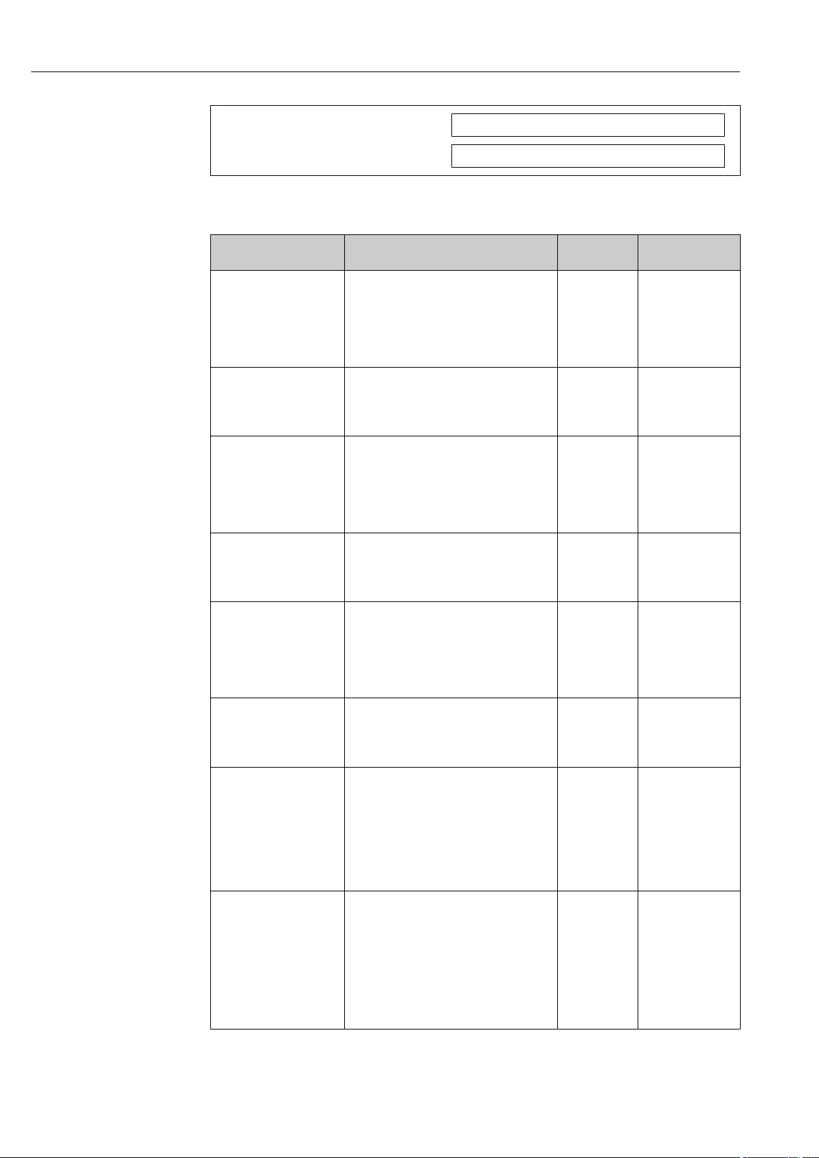
Commissioning Proline Promass I 100 Modbus RS485
Temperature unit
Pressure unit
Parameter overview with brief description
Parameter Description Selection/
User entry
Mass flow unit Select the unit for mass flow.
Result
The selected unit applies for:
– Output
– Low flow cut off
– Simulation process variable
Mass unit Select the unit for mass.
Result
The selected unit is taken from:
Mass flow unit
Volume flow unit Select the unit for volume flow.
Result
The selected unit applies for:
– Output
– Low flow cut off
– Simulation process variable
Volume Select the unit for volume.
Result
The selected unit is taken from:
Volume flow unit
Corrected volume flow
unit
Corrected volume unit Select the unit for standard volume.
Density unit Select the unit for density.
Reference density unit Select the unit for reference density.
Select the unit for corrected volume flow.
Result
The selected unit applies for:
– Output
– Low flow cut off
– Simulation process variable
Result
The selected unit is taken from:
Corrected volume flow unit
Result
The selected unit applies for:
– Output
– Low value partial filled pipe detection
– High value partial filled pipe detection
– Simulation process variable
– Density adjustment (in the Expert menu)
Result
The selected unit applies for:
– Output
– Low value partial filled pipe detection
– High value partial filled pipe detection
– Simulation process variable
– Fixed reference density
– Density adjustment (in the Expert menu)
Unit choose list Country-dependent:
Unit choose list Country-dependent:
Unit choose list Country-dependent:
Unit choose list Country-dependent:
Unit choose list Country-dependent:
Unit choose list Country-dependent
Unit choose list Country-dependent:
Factory setting
• kg/h
• lb/min
• kg
• lb
• l/h
• gal/min (us)
Country-dependent
• l
• gal (us)
• Nl/h
• Scf/min
• Nl
• Scf
• kg/l
• lb/cf
• kg/Nl
• lb/Scf
44 Endress+Hauser
Page 45

Proline Promass I 100 Modbus RS485 Commissioning
Parameter Description Selection/
User entry
Temperature unit Select the unit for temperature.
Result
The selected unit applies for:
– Output
– Reference temperature
– Simulation process variable
Pressure unit Select the unit for pipe pressure. Unit choose list Country-dependent:
Unit choose list Country-dependent:
Factory setting
• °C (Celsius)
• °F (Fahrenheit)
• bar a
• psi a
Endress+Hauser 45
Page 46
Commissioning Proline Promass I 100 Modbus RS485
10.3.2 Selecting and setting the medium
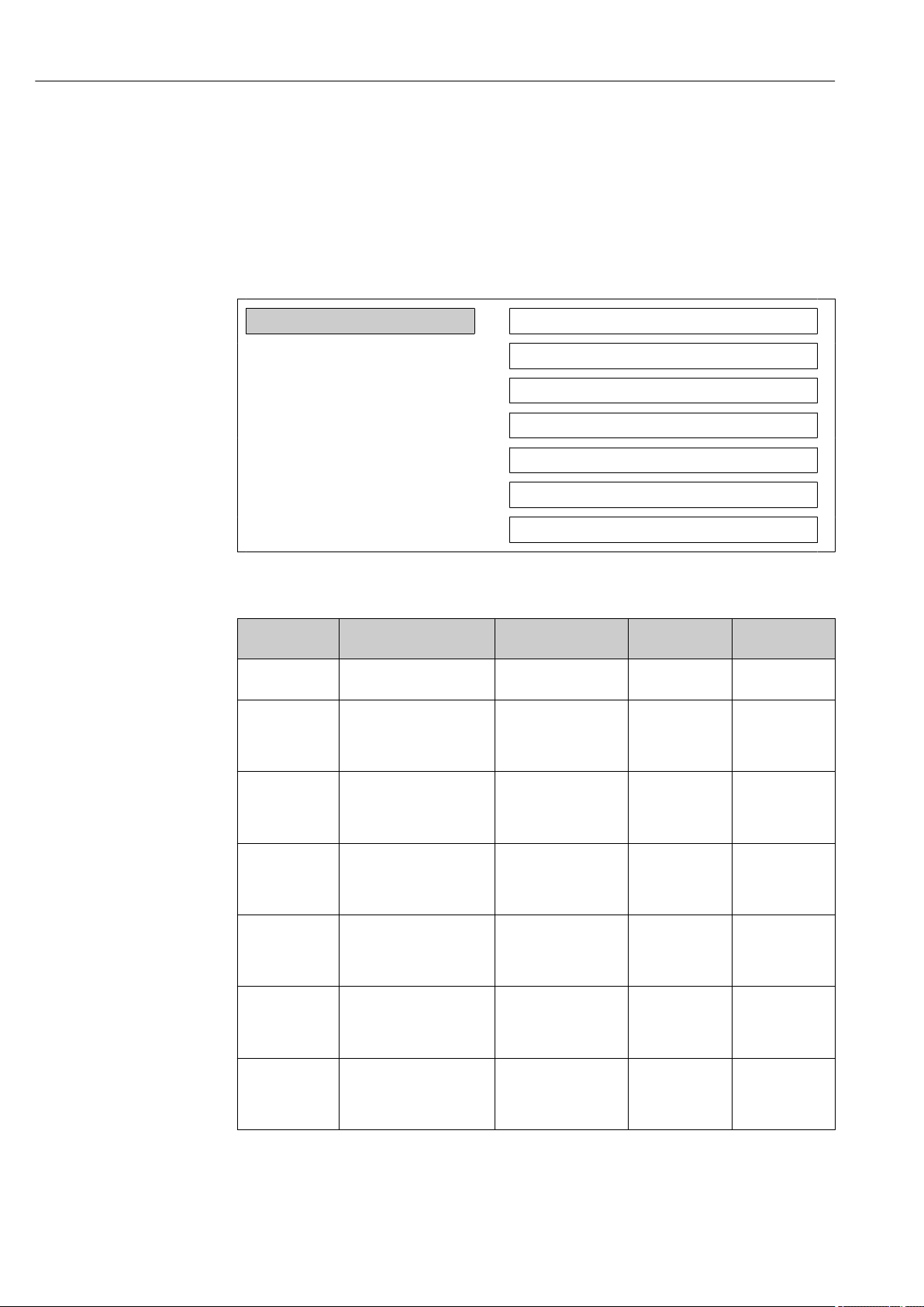
The Medium selection submenu contains parameters that have to be configured for
selecting and setting the medium.
Navigation path
"Setup" menu Medium selection
Structure of the submenu
Medium selection
Select medium
Select gas type
Reference sound velocity
Temperature coefficient sound velocity
Pressure compensation
Pressure value
External pressure
Parameter overview with brief description
Parameter Prerequisite Description Selection/
User entry
Medium
selection
Select gas type The following option is
Reference sound
velocity
Temperature
coefficient sound
velocity
Pressure
compensation
Pressure value The following option is
External
pressure
– Select the medium
type.
Select the gas type for
selected in the Medium
selection parameter:
Gas
The following option is
selected in the Select gas
type parameter:
Others
The following option is
selected in the Select gas
type parameter:
Others
The following option is
selected in the Medium
selection parameter:
Gas
selected in the Pressure
compensation parameter:
Fixed value
The following option is
selected in the Pressure
compensation parameter:
External value
the measurement
application.
Enter the sound
velocity of the gas at
0°C (32°F).
Enter the temperature
coefficient of the sound
velocity of the gas.
Enable the automatic
pressure correction.
Enter a value for the
process pressure to be
used for pressure
correction.
External value 0 to 99 999 [bar,
• Liquid
• Gas
Gas type choose
list
0 to 99 999 m/s 0 m/s
Max. 15-digit,
positive floatingpoint number
• Off
• Fixed value
0 to 99 999 [bar,
psi]
psi]
Factory setting
Liquid
Air
0 (m/s)/K
Off
Countrydependent:
• 1.01325 bar
• 14.7 psi
Countrydependent:
• 1.01325 bar
• 14.7 psi
46 Endress+Hauser
Page 47
Proline Promass I 100 Modbus RS485 Commissioning
10.3.3 Configuring communication interface
The Communication submenu guides you systematically through all parameters that must
be configured for selecting and setting the communication interface.
Navigation path
"Setup" menu Communication
Structure of the submenu
Communication
Bus address
Baud rate
Data transfer mode
Parity
Byte order
Assign diagnostic behavior
Failure mode
Parameter overview with brief description
Parameter Description
Bus address Enter device address. 1 to 247 247
Baud rate Define data transfer
speed.
Data transfer mode Select data transfer mode. • ASCII
Parity Select parity bits. ASCII picklist
Byte order Select byte transmission
sequence.
Selection/
User entry
Baud rate list
box( 79)
Transmission of data in
the form of readable
ASCII characters. Error
protection via LRC.
• RTU
Transmission of data in
binary form. Error
protection via CRC16.
• 0 = even
• 1 = odd
RTU picklist
• 0 = even
• 1 = odd
• 2 = no parity bit/1 stop
bit
• 3 = no parity bit/2 stop
bits
• 0-1-2-3
• 3-2-1-0
• 1-0-3-2
• 2-3-0-1
Factory setting
19 200 BAUD
RTU
Even
1-0-3-2
Endress+Hauser 47
Page 48
Commissioning Proline Promass I 100 Modbus RS485
Parameter Description
Assign diagnostic
behavior
Failure mode Select measured value
Select diagnostic behavior
for MODBUS
communication.
output behavior when a
diagnostic message occurs
via Modbus
communication.
This parameter
operates in
accordance with the
option selected in
the Assign
diagnostic
behavior
parameter.
Selection/
User entry
• Off
• Alarm or warning
• Warning
• Alarm
• NaN value
• Last valid value
NaN º not a number
Factory setting
Alarm
NaN value
48 Endress+Hauser
Page 49
Proline Promass I 100 Modbus RS485 Commissioning
10.3.4 Configuring the low flow cut off
The Low flow cut off submenu contains parameters that have to be set for configuring the
low flow cut off.
Navigation path
"Setup" menu Low flow cut off
Structure of the submenu
Low flow cut off
Assign process variable
On value low flow cut off
Off value low flow cutoff
Pressure shock suppression
Parameter overview with brief description
Parameter Prerequisite Description Selection/
User entry
Assign process
variable
On value low
flow cut off
Off value low
flow cut off
Pressure shock
suppression
– Select the process
variable for low flow cut
off.
One of the following options
is selected in the Assign
process variable parameter:
• Mass flow
• Volume flow
• Corrected volume flow
One of the following options
is selected in the Assign
process variable parameter:
• Mass flow
• Volume flow
• Corrected volume flow
One of the following options
is selected in the Assign
process variable parameter:
• Mass flow
• Volume flow
• Corrected volume flow
Enter the on value for
low flow cut off.
Enter the off value for
low flow cut off.
Enter the time interval
for signal suppression (=
active pressure shock
suppression).
• Off
• Mass flow
• Volume flow
• Corrected
volume flow
Max. 15-digit,
positive floatingpoint number
0 to 100 % 50 %
0 to 100 s 0 s
Factory
setting
Mass flow
For liquids:
depends on
country and
nominal
diameter
Endress+Hauser 49
Page 50
Commissioning Proline Promass I 100 Modbus RS485
10.3.5 Configuring the partial filled pipe detection
The Partially filled pipe detection submenu contains parameters that have to be set for
configuring empty pipe detection.
Navigation path
"Setup" menu Partial filled pipe detection
Structure of the submenu
Partially filled pipe detection
Assign process variable
Low value partial filled pipe detection
High value partial filled pipe detection
Response time part. filled pipe detect.
Parameter overview with brief description
Parameter Prerequisite Description Selection/
User entry
Assign process
variable
Low value
partial filled
pipe detection
High value
partial filled
pipe detection
Response time
part. filled pipe
detect.
– Select a process variable to
detect empty or partially
filled pipes.
One of the following
options is selected in the
Assign process variable
parameter:
• Density
• Reference density
One of the following
options is selected in the
Assign process variable
parameter:
• Density
• Reference density
One of the following
options is selected in the
Assign process variable
parameter:
• Density
• Reference density
Enter a lower limit value to
activate detection of an
empty or partially filled
pipe.
Enter an upper limit value
to activate detection of an
empty or partially filled
pipe.
Enter the time interval
until the diagnostic
message S862 Partly
filled pipe detection is
displayed for an empty or
partially filled pipe.
• Off
• Density
• Reference
density
Max. 15-digit,
positive floatingpoint number
Max. 15-digit,
positive floatingpoint number
0 to 100 s 1 s
Factory setting
Density
Countrydependent:
• 0.2 kg/l
• 12.5 lb/cf
Countrydependent:
• 6 kg/l
• 374.6 lb/cf
50 Endress+Hauser
Page 51
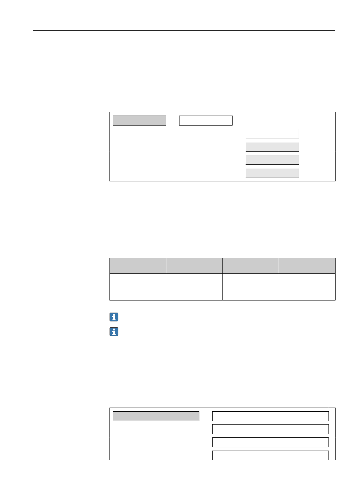
Proline Promass I 100 Modbus RS485 Commissioning
10.4 Advanced settings
The Advanced setup menu with its submenus contains all parameters needed for specific
settings.
Navigation path
"Setup" menu Advanced setup
Overview of the parameters and submenus in the "Advanced setup" menu taking the
example of the Web browser
Advanced setup
Enter access code
Device tag
Calculated values
Sensor adjustment
Totalizer 1 to 3
( 51)
( 51)
( 52)
( 53)
10.4.1 Defining the tag name
To enable quick identification of the measuring point within the system, you can enter a
unique designation using the Device tag parameter and thus change the factory setting.
Navigation path
Setup Advanced setup Device tag
Parameter overview with brief description
Parameter Description
Device tag Enter the name for the
measuring point.
Selection/
User entry
Max. 32 characters, such
as letters, numbers or
special characters (e.g. @,
%, /)
Factory setting
Promass
The number of characters displayed depends on the characters used.
For information on the tag name in the "FieldCare" operating tool ( 38)
10.4.2 Calculated values
The Calculated values submenu contains parameters for calculating the corrected volume
flow.
Navigation path
"Setup" menu Advanced setup Calculated values
Structure of the submenu
Calculated values
Endress+Hauser 51
Corrected volume flow calculation
External reference density
Fixed reference density
Reference temperature
Page 52

Commissioning Proline Promass I 100 Modbus RS485
Linear expansion coefficient
Square expansion coefficient
Parameter overview with brief description
Parameter Prerequisites Description Selection/input Factory settings
Corrected
volume flow
calculation
External
reference
density
Fixed
reference
density
Reference
temperature
Linear
expansion
coefficient
Square
expansion
coefficient
– Select the reference
density for
calculating the
corrected volume
flow.
– Shows external
reference density.
The following
option is selected in
the Corrected
volume flow
calculation
parameter:
Fixed reference
density
The following
option is selected in
the Corrected
volume flow
calculation
parameter:
Calculated reference
density
The following
option is selected in
the Corrected
volume flow
calculation
parameter:
Calculated reference
density
– For media with a
Enter the fixed value
for the reference
density.
Enter the reference
temperature for
calculating the
reference density.
Enter the linear,
medium-specific
expansion coefficient
for calculating the
reference density.
non-linear expansion
pattern, use this
function to enter a
quadratic, mediumspecific expansion
coefficient for
calculating the
reference density.
• Fixed reference
density
• Calculated
reference
density
• Reference
density
according to
API 53
• External
reference
density
Floating-point
number with sign
Positive floatingpoint number
with leading sign
Floating-point
number with sign
0 to 1 0.0
0 to 1 0.0
Calculated reference density
Country-dependent:
0 kg/Nl (0 lb/scf)
Country-dependent:
0.001 kg/Nl (0.062 lb/scf)
Country-dependent:
20 °C (68 ° F)
10.4.3 Carrying out a sensor adjustment
The Sensor adjustment submenu contains parameters that pertain to the functionality of
the sensor.
52 Endress+Hauser
Page 53
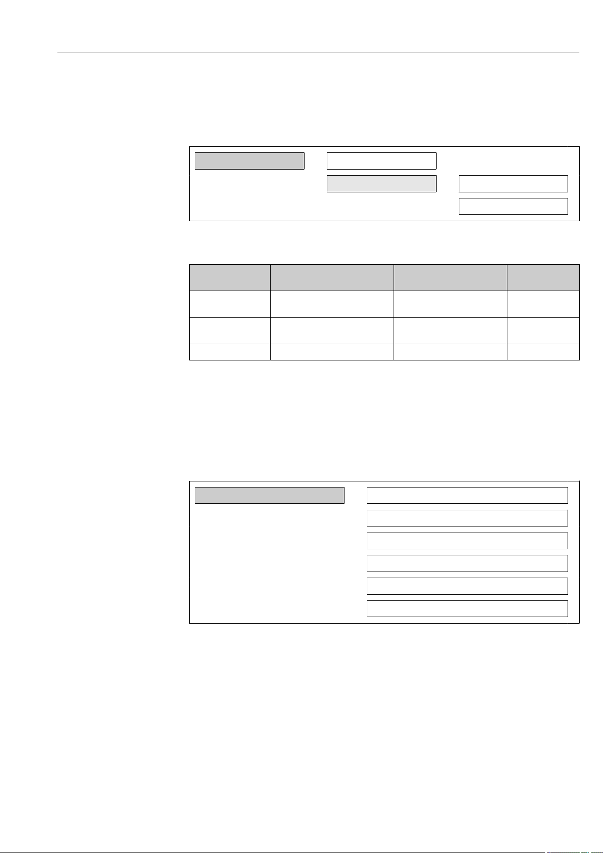
Proline Promass I 100 Modbus RS485 Commissioning
Navigation path
"Setup" menu Advanced setup Sensor adjustment
Structure of the submenu
Sensor adjustment
Installation direction
Zero point adjustment
Zero point adjustment control
Progress
Parameter overview with brief description
Parameter Description Selection/
User entry
Installation direction Change the sign of the direction
of flow of the fluid.
Zero point
adjustment control
Progress 0…100 % 0
Start the zero point adjustment. • Cancel
• Flow in arrow direction
• Flow against arrow direction
• Start
10.4.4 Configuring the totalizer
You can configure each totalizer in the three submenus Totalizer 1-3.
Navigation path
"Setup" menu Advanced setup Totalizer 1-3
Factory setting
Flow in arrow
direction
Cancel
Structure of the submenu
Totalizer 1-3
Assign process variable
Mass unit
Volume unit
Corrected volume unit
Totalizer operation mode
Failure mode
Endress+Hauser 53
Page 54

Commissioning Proline Promass I 100 Modbus RS485
Parameter overview with brief description
Parameter Prerequisite Description
Assign process
variable
Mass unit The following option
Volume unit The following option
Corrected volume
unit
Totalizer operation
mode
Failure mode One of the following
- Select process
variable for totalizer.
Result
The selection
determines the
choose list of the
Unit parameter.
Select the unit for
is selected in the
Assign process
variable parameter:
Mass flow
is selected in the
Assign process
variable parameter:
Volume flow
The following option
is selected in the
Assign process
variable parameter:
Corrected volume
flow
One of the following
options is selected in
the Assign process
variable parameter:
• Mass flow
• Volume flow
• Corrected volume
flow
options is selected in
the Assign process
variable parameter:
• Mass flow
• Volume flow
• Corrected volume
flow
mass.
Result
The selected unit is
taken from:
Mass flow unit
Select the unit for
volume.
Result
The selected unit is
taken from:
Volume flow unit
Select the unit for
standard volume.
Result
The selected unit is
taken from:
Corrected volume
flow unit
Select totalizer
calculation mode.
Specify the behavior
of the totalizer in
the event of a device
alarm.
Selection/
User entry
• Off
• Mass flow
• Volume flow
• Corrected volume
flow
The range of
options
increases if
the measuring
device has one
or more
application
packages.
Unit choose list Country-dependent:
Unit choose list Country-dependent
Unit choose list Country-dependent:
• Net flow total
• Forward flow
total
• Reverse flow total
• Stop
• Actual value
• Last valid value
Factory setting
Mass flow
• kg
• lb
• l
• gal (us)
• Nl
• Scf
Net flow total
Stop
10.5 Simulation
The Simulation submenu enables you to simulate, without a real flow situation, various
process variables in the process and the device alarm mode and to verify downstream
signal chains (switching valves or closed-control loops).
54 Endress+Hauser
Page 55
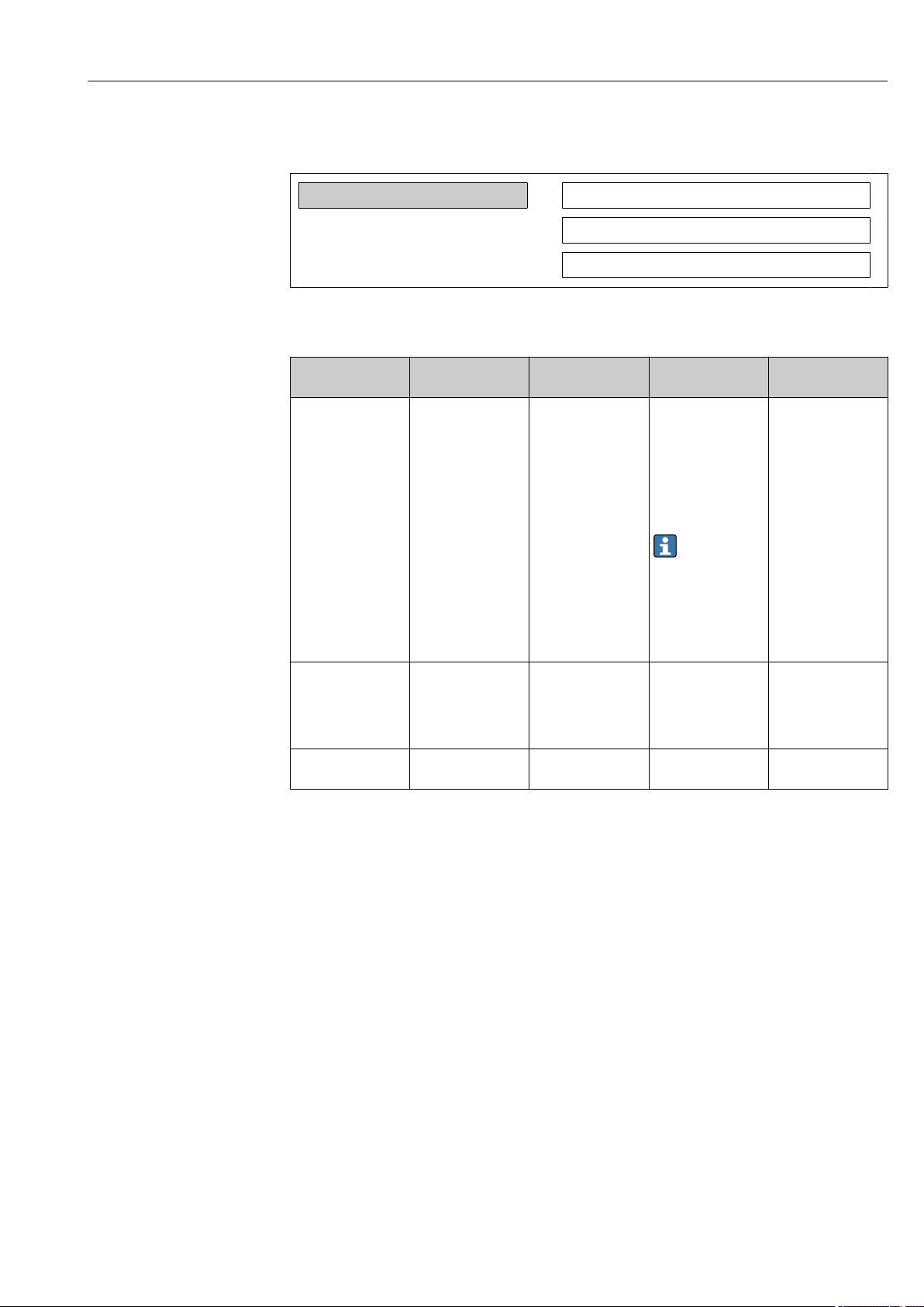
Proline Promass I 100 Modbus RS485 Commissioning
Navigation path
"Diagnostics" menu Simulation
Simulation
Assign simulation process variable
Value process variable
Simulation device alarm
10.5.1 Parameter overview with brief description
Parameter Prerequisite Description
Assign simulation
process variable
Value process
variable
Simulation device
alarm
- Select a process
variable for the
simulation process
that is activated.
A process variable is
selected in the
Assign simulation
process variable
parameter.
- Switch the device
Enter the simulation
value for the
selected process
variable.
alarm on and off.
Selection/
User entry
• Off
• Mass flow
• Volume flow
• Corrected volume
flow
• Density
• Reference density
• Temperature
The range of
options
increases if
the measuring
device has one
or more
application
packages.
Depends on the
process variable
selected
• Off
• On
Factory setting
Off
-
Off
10.6 Protecting settings from unauthorized access
The following option exists for protecting the configuration of the measuring device from
unintentional modification after commissioning: Write protection via write protection
switch
10.6.1 Write protection via write protection switch
The write protection switch makes it possible to block write access to the entire operating
menu with the exception of the following parameters:
• External pressure
• External temperature
• Reference density
• All parameters for configuring the totalizer
The parameter values are now read only and cannot be edited any more:
• Via service interface (CDI)
• Via Modbus RS485
Endress+Hauser 55
Page 56
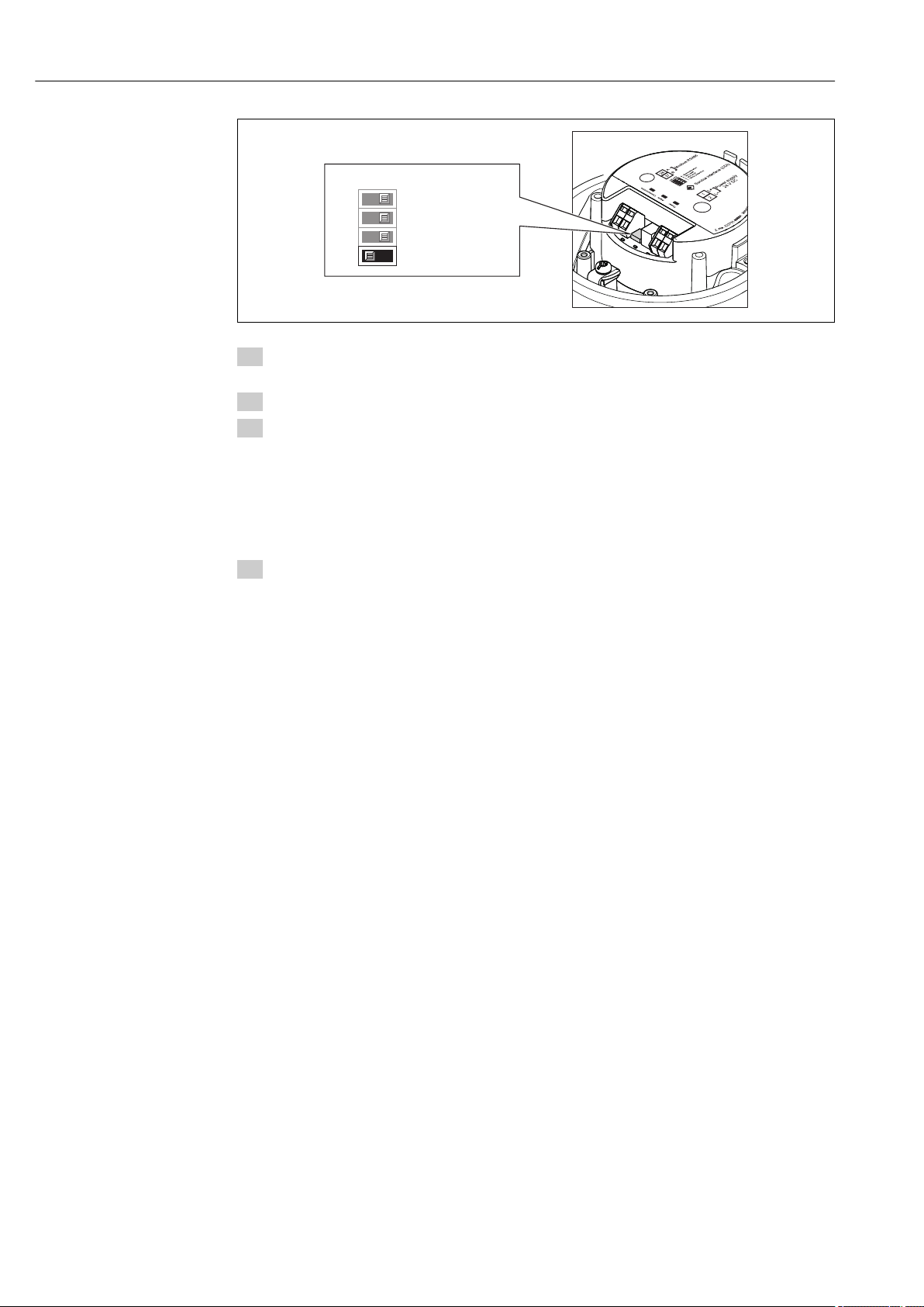
Commissioning Proline Promass I 100 Modbus RS485
OFFON
1 - Write protection
2 - Not used
3 - Not used
4 - Bus termination
A0017954
1. Depending on the housing version, loosen the securing clamp or fixing screw of the
housing cover.
2. Depending on the housing version, unscrew or open the housing cover.
3. Setting the write protection switch on the main electronics module to the ON position
enables the hardware write protection. Setting the write protection switch on the
main electronics module to the OFF position (factory setting) disables the hardware
write protection.
If hardware write protection is enabled, the Hardware locked option is displayed
in the Locking status parameter ( 57); if disabled, no option is displayed
in the Locking status parameter ( 57)
4. Reverse the removal procedure to reassemble the transmitter.
56 Endress+Hauser
Page 57
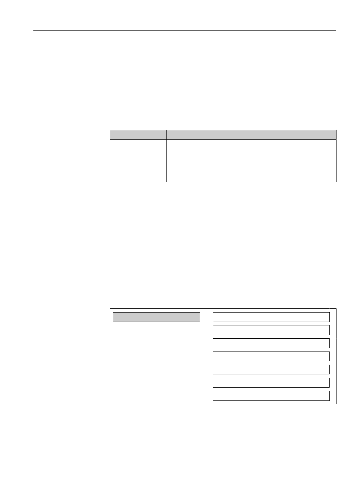
Proline Promass I 100 Modbus RS485 Operation
11 Operation
11.1 Read device locking status
The write protection types that are currently active can be determined using the Locking
status parameter.
Navigation path
"Display/operation" menu Locking status
Function scope of "Locking status" parameter
Options Description
Hardware locked The write protection switch (DIP switch) for hardware locking is activated on the
main electronics module. This prevents write access to the parameters ( 55).
Temporarily locked Write access to the parameters is temporarily locked on account of internal
processes running in the device (e.g. data upload/download, reset etc). Once the
internal processing has been completed, the parameters can be changed once
again.
11.2 Reading measured values
You can read all measured values using the Measured values menu.
Navigation path
Diagnostics Measured values
11.2.1 Process variables
The Process variables submenu contains all the parameters needed to display the current
measured values for every process variable.
Navigation path
"Diagnostics" menu Measured values Process variables
Structure of the submenu
Process variable
Mass flow
Volume flow
Corrected volume flow
Density
Reference density
Temperature
Pressure value
Endress+Hauser 57
Page 58
Operation Proline Promass I 100 Modbus RS485
Parameter overview with brief description
Parameter overview with brief description
Parameter Prerequisite Description Display
Mass flow – Displays the mass flow currently
measured
Volume flow – Displays the volume flow currently
calculated
Corrected volume
flow
Density – Displays the density currently measured Floating-point number with
Reference density – Displays the density currently measured
Temperature – Displays the medium temperature
Pressure value – Displays either a fixed or external
– Displays the corrected volume flow
currently calculated
at reference temperature
currently measured
pressure value
Floating-point number with
sign
Floating-point number with
sign
Floating-point number with
sign
sign
Floating-point number with
sign
Floating-point number with
sign
Floating-point number with
sign
11.2.2 Totalizer
The Totalizer submenu contains all the parameters needed to display the current
measured values for every totalizer.
Navigation path
"Diagnostics" menu Measured values Totalizer
Structure of the submenu
Totalizer 1 to 3
Totalizer value 1
Totalizer overflow 1
Totalizer value 2
Totalizer overflow 2
Totalizer value 3
Totalizer overflow 3
58 Endress+Hauser
Page 59
Proline Promass I 100 Modbus RS485 Operation
Parameter overview with brief description
Parameter Prerequisite Description Display
Totalizer value 1-3 One of the following
options is selected in the
Assign process variable
parameter of the
Totalizer 1-3 submenu:
• Mass flow
• Volume flow
• Corrected volume flow
Totalizer overflow 1-3 One of the following
options is selected in the
Assign process variable
parameter of the
Totalizer 1-3 submenu:
• Mass flow
• Volume flow
• Corrected volume flow
Displays the current
totalizer counter value.
Displays the current
totalizer overflow.
Floating point number
with sign
Integer
11.3 Adapting the measuring device to the process conditions
The following are available for this purpose:
• Basic settings using the Setup menu ( 43)
• Advanced settings using the Advanced setup menu ( 51)
11.4 Performing a totalizer reset
In the Operation submenu, 2 parameters with various options for resetting the three
totalizers are available:
• Control totalizer 1-3
• Reset all totalizers
Navigation path
"Display/operat." menu Operation
Function scope of the "Control totalizer" parameter
Options Description
Totalize The totalizer is started.
Reset + hold The totaling process is stopped and the totalizer is reset to 0.
Preset + hold The totaling process is stopped and the totalizer is set to the defined start value in
the Preset parameter.
Reset + totalize The totalizer is reset to 0 and the totaling process is restarted.
Preset + totalize The totalizer is set to the defined start value in the Preset parameter and the
totaling process is restarted.
Function scope of the "Reset all totalizers" parameter
Options Description
Reset + totalize Resets all totalizers to 0 and restarts the totaling process. This deletes all the flow
values previously totalized.
Endress+Hauser 59
Page 60
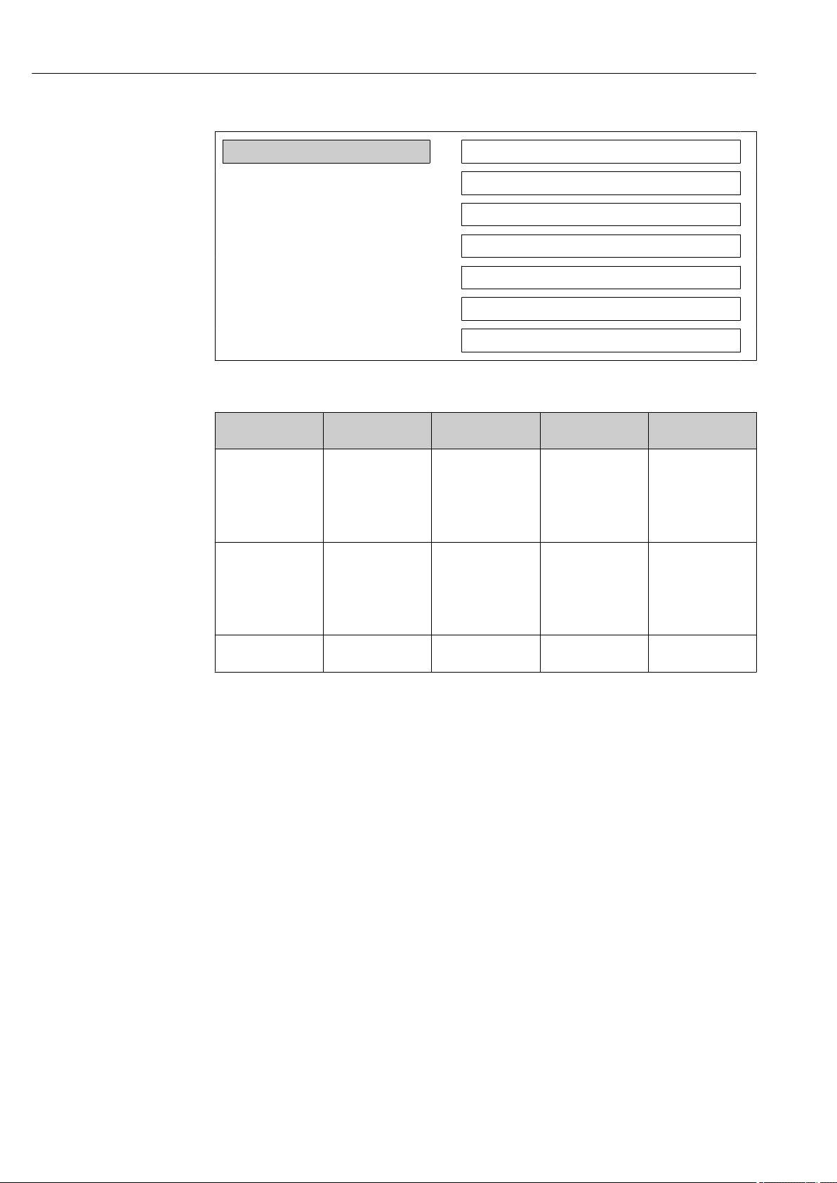
Operation Proline Promass I 100 Modbus RS485
"Operation" submenu
Operation
Control totalizer 1
Preset value 1
Control totalizer 2
Preset value 2
Control totalizer 3
Preset value 3
Reset all totalizers
Parameter overview with brief description
Parameter Prerequisite Description
Control totalizer 1-3 A process variable is
selected in the
Assign process
variable parameter
of the Totalizer 1-3
submenu.
Preset value 1-3 A process variable is
selected in the
Assign process
variable parameter
of the Totalizer 1-3
submenu.
Reset all totalizers - Reset all totalizers
Control totalizer
value.
Specify start value
for totalizer.
to 0 and start.
Selection/
User entry
• Totalize
• Reset + hold
• Preset + hold
• Reset + totalize
• Preset + totalize
Floating-point
number with sign
• Cancel
• Reset + totalize
Factory setting
Totalize
Country-dependent:
• 0 kg
• 0 lb
Cancel
60 Endress+Hauser
Page 61
Proline Promass I 100 Modbus RS485 Diagnostics and troubleshooting
12 Diagnostics and troubleshooting
12.1 General troubleshooting
For output signals
Problem Possible causes Remedy
Green power LED on the main
electronics module of the
transmitter is dark
Green power LED on the main
electronics module of the
transmitter is dark
Green power LED on Safety Barrier
Promass 100 is dark
Green power LED on Safety Barrier
Promass 100 is dark
Device measures incorrectly. Configuration error or device is
Supply voltage does not match that
specified on the nameplate.
Power supply cable connected
incorrectly
Supply voltage does not match that
specified on the nameplate.
Power supply cable connected
incorrectly
operated outside the application.
Apply the correct supply voltage
( 30).
Check the terminal assignment .
Apply the correct supply voltage
( 30).
Check the terminal assignment
( 28).
1. Check and correct parameter
configuration.
2. Observe limit values specified in
the "Technical Data".
For access
Problem Possible causes Remedy
No write access to parameters Hardware write protection enabled Set the write protection switch on
the main electronics module to the
OFF position ( 55).
No connection via Modbus RS485 Modbus RS485 bus cable connected
incorrectly
No connection via Modbus RS485 Device plug connected incorrectly Check the pin assignment of the
No connection via Modbus RS485 Modbus RS485 cable incorrectly
terminated
No connection via Modbus RS485 Incorrect settings for the
communication interface
No connection via service interface Incorrect configuration of USB
interface on PC or driver not
installed correctly.
Check the terminal assignment .
device plug ( 28).
Check terminating resistor
( 32).
Check the Modbus RS485
configuration ( 47).
Observe the documentation for the
Commubox.
FXA291: Document
"Technical Information"
TI00405C
12.2 Diagnostic information via light emitting diodes
12.2.1 Transmitter
Various light emitting diodes (LEDs) on the main electronics module of the transmitter
provide information on device status.
LED Color Meaning
Power Off Supply voltage is off or too low.
Green Supply voltage is ok.
Endress+Hauser 61
Page 62
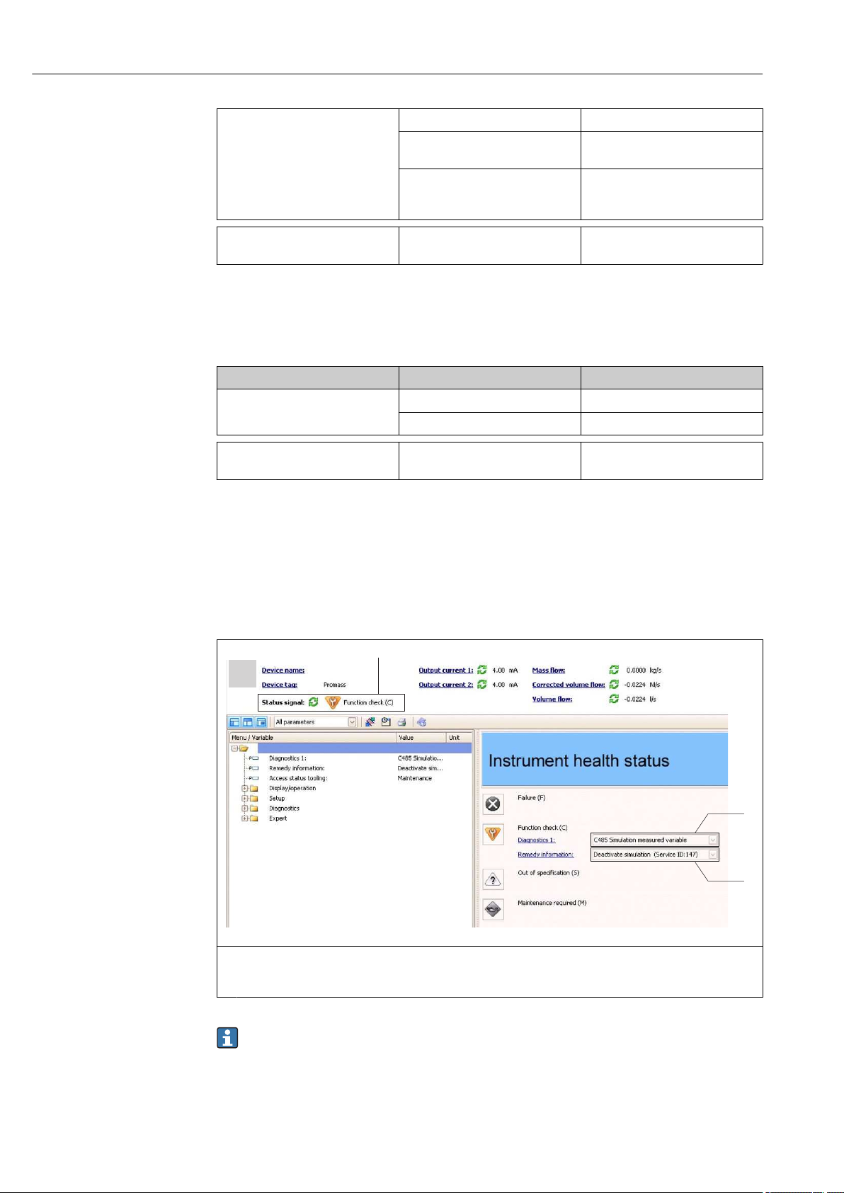
Diagnostics and troubleshooting Proline Promass I 100 Modbus RS485
2
3
1
XXXXXXX
XXXXXXX
Alarm Off Device status is ok.
Flashing red A device error of diagnostic
behavior "Warning" has occurred.
Red • A device error of diagnostic
behavior "Alarm" has occurred.
• Boot loader is active.
Communication Flashing white Modbus RS485 communication is
active.
12.2.2 Safety Barrier Promass 100
Various light emitting diodes (LEDs) on the Safety Barrier Promass 100 provide status
information.
LED Color Meaning
Power Off Supply voltage is off or too low.
Green Supply voltage is ok.
Communication Flashing white Modbus RS485 communication is
active.
12.3 Diagnostic information in FieldCare
12.3.1 Diagnostic options
Any faults detected by the measuring device are displayed on the home page of the
operating tool once the connection has been established.
A0014014-EN
1
Status area with status signal
2
Diagnostic information
3
Remedy information with Service ID
Furthermore, diagnostic events that have occurred can be viewed in the Diagnostics
menu:
• Via parameters
• Via submenu ( 67)
62 Endress+Hauser
Page 63
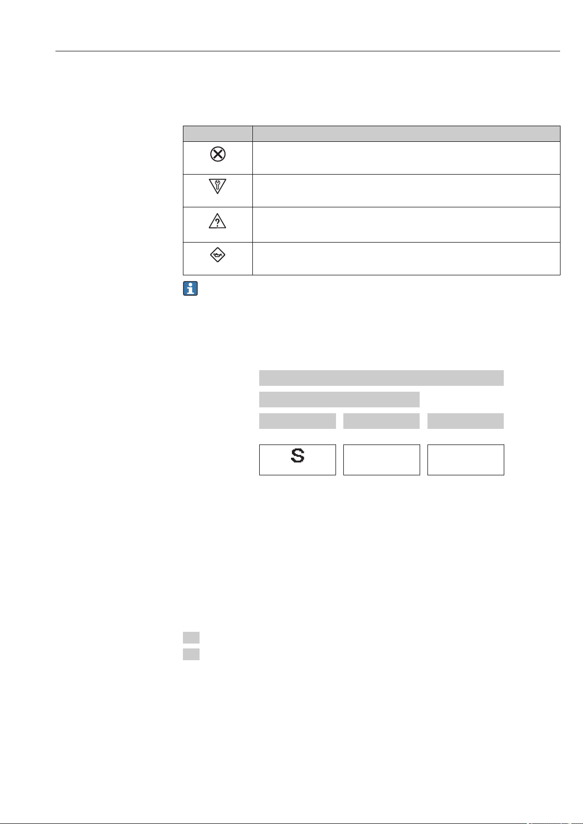
Proline Promass I 100 Modbus RS485 Diagnostics and troubleshooting
Status signals
The status signals provide information on the state and reliability of the device by
categorizing the cause of the diagnostic information (diagnostic event).
Symbol Meaning
Failure
A device error has occurred. The measured value is no longer valid.
A0017271
Function check
The device is in service mode (e.g. during a simulation).
A0017278
Out of specification
The device is operated:
Outside its technical specification limits (e.g. outside the process temperature range)
A0017277
Maintenance required
Maintenance is required. The measured value is still valid.
A0017276
The status signals are categorized in accordance with VDI/VDE 2650 and NAMUR
Recommendation NE 107.
Diagnostic information
The fault can be identified using the diagnostic information. The short text helps you by
providing information about the fault.
Diagnostic information
Diagnostic code
Status signal Diagnostic number Short text
Example
A0013958
842 Process limit
3-digit number
12.3.2 Calling up remedy information
Remedy information is provided for every diagnostic event to ensure that problems can be
rectified quickly:
• On the home page
Remedy information is displayed in a separate field below the diagnostics information.
• In the Diagnostics menu
Remedy information can be called up in the working area of the user interface.
The user is in the Diagnostics menu.
1. Call up the desired parameter.
2. On the right in the working area, mouse over the parameter.
A tool tip with remedy information for the diagnostic event appears.
12.4 Diagnostic information via communication interface
12.4.1 Reading out diagnostic information
Diagnostic information can be read out via Modbus RS485 register addresses.
Endress+Hauser 63
Page 64
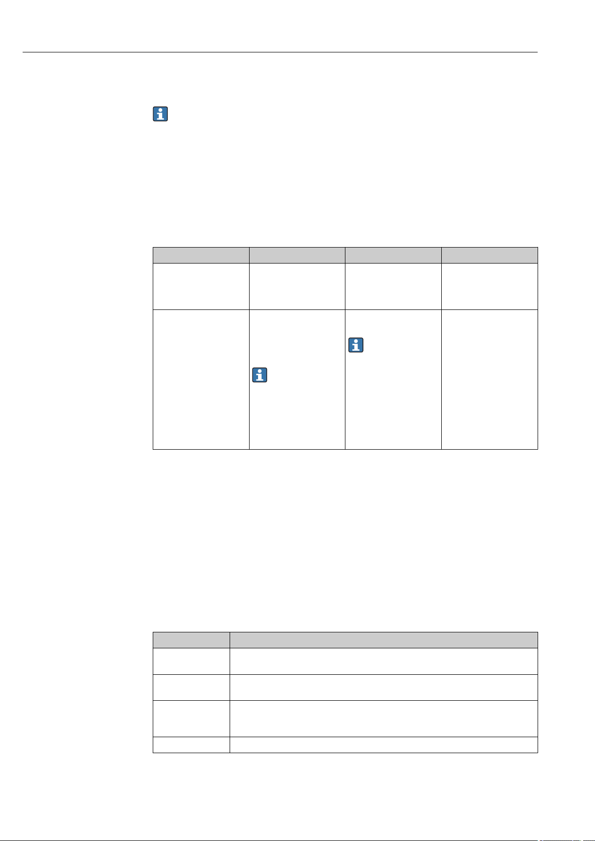
Diagnostics and troubleshooting Proline Promass I 100 Modbus RS485
• Via register address 6821 (data type = string): diagnosis code, e.g. F270
• Via register address 6859 (data type = integer): diagnosis number, e.g. 270
For an overview of diagnostic events with diagnosis number and diagnosis code
( 65)
12.4.2 Configuring error response mode
Error response mode for Modbus RS485 communication can be configured in the
Communication submenu using 2 parameters.
Navigation path
"Setup" menu Communication
Parameter overview with brief description
Parameter Description Options Factory setting
Assign diagnostic
behavior
Failure mode Select measured value
Select diagnostic behavior
for MODBUS
communication.
output behavior when a
diagnostic message occurs
via Modbus
communication.
This parameter
operates in
accordance with the
option selected in
the Assign
diagnostic
behavior
parameter.
• Off
• Alarm or warning
• Warning
• Alarm
• NaN value
• Last valid value
NaN º not a number
Alarm
NaN value
12.5 Adapting the diagnostic information
12.5.1 Adapting the diagnostic behavior
Each diagnostic number is assigned a certain diagnostic behavior at the factory. The user
can change this assignment for certain diagnostic numbers via the Diagnostic no. xxx
parameter.
Navigation path
"Expert" menu System Diagnostic handling Diagnostic behavior Assign behavior
of diagnostic no. xxx
You can assign the following options to the diagnostic number as the diagnostic behavior:
Options Description
Alarm Measurement is interrupted. Measured value output via Modbus RS485 and totalizers
assume the defined alarm condition. A diagnostic message is generated.
Warning Measurement is resumed. Measured value output via Modbus RS485 and totalizers are
not affected. A diagnostic message is generated.
Logbook entry only The device continues to measure. The diagnostic message is entered in the Event
logbook (events list) submenu only and is not displayed in alternation with the measured
value display.
Off The diagnostic event is ignored, and no diagnostic message is generated or entered.
64 Endress+Hauser
Page 65
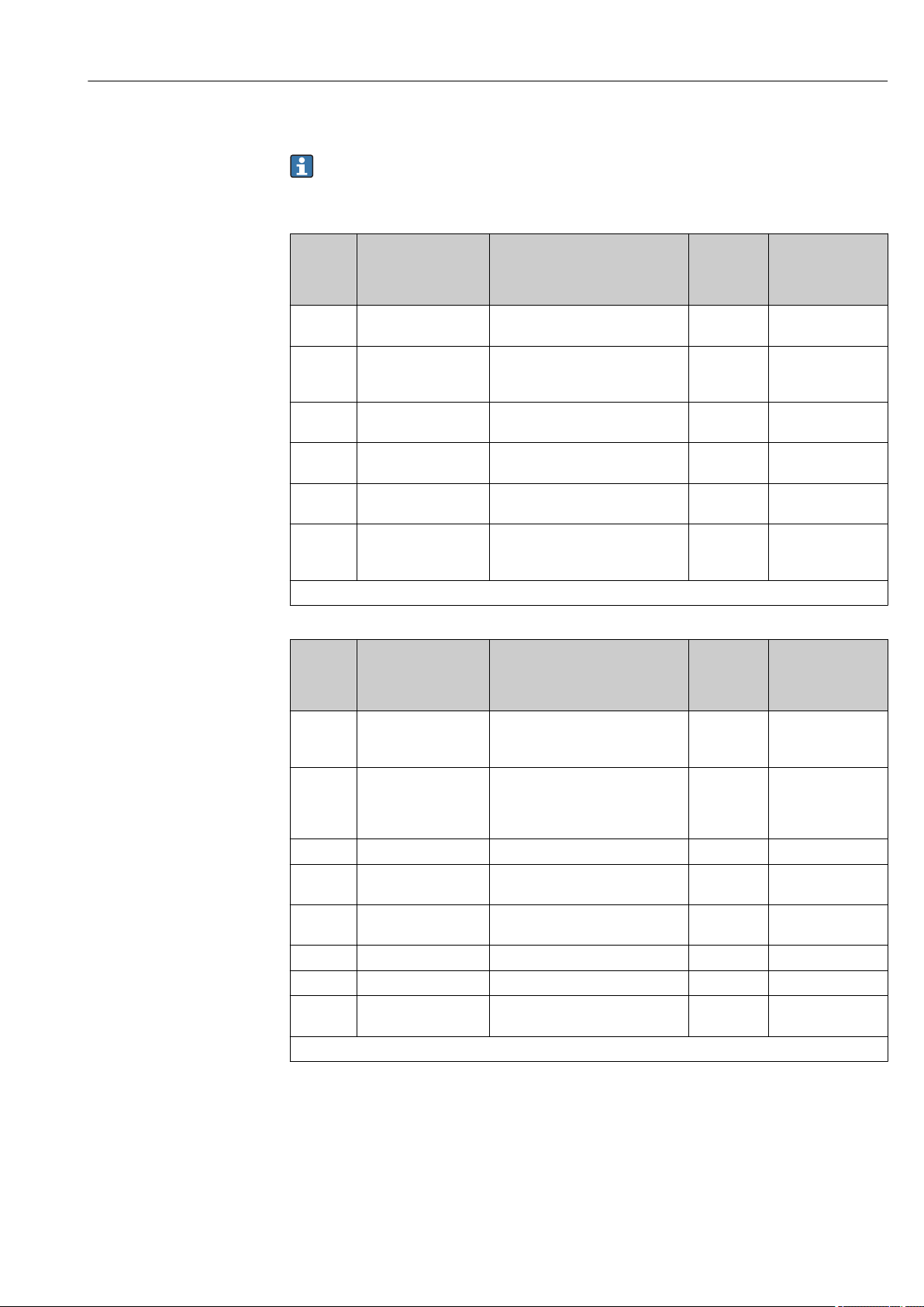
Proline Promass I 100 Modbus RS485 Diagnostics and troubleshooting
12.6 Overview of diagnostic information
The amount of diagnostic information increases if the measuring device has one or
more application packages.
Diagnostics for the sensor
Status
Diagnosti
c number
022 Sensor temperature 1. Change main electronic module.
044 Sensor drift 1. Check or change main
046 Sensor limit 1. Inspect sensor.
062 Sensor connection 1. Change main electronic module.
082 Data storage 1. Change main electronic module.
083 Memory content 1. Restart device.
*
Diagnostic behavior can be changed: "Adapting the diagnostic behavior" section ( 64)
Short text Remedial measures
2. Change sensor.
electronics.
2. Change sensor.
2. Check process conditions.
2. Change sensor.
2. Change sensor.
2. Restore S-DAT data.
3. Change sensor.
signal
from the
factory
F Alarm
S Alarm
S Alarm
F Alarm
F Alarm
F Alarm
Diagnostic
from the factory
Diagnostics for the electronics
Status
Diagnosti
c number
242 Software incompatible 1. Check software.
261 Electronic modules 1. Restart device.
270 Main electronic failure Change main electronic module. F Alarm
271 Main electronic failure 1. Restart device.
272 Main electronic failure 1. Restart device.
273 Main electronic failure Replace electronics. F Alarm
274 Main electronic failure Replace electronics. S Warning
311 Electronic failure 1. Transfer data or reset device.
*
Diagnostic behavior can be changed: "Adapting the diagnostic behavior" section ( 64)
Short text Remedial measures
2. Flash or change main electronic
module.
2. Check electronic modules.
3. Change I/O module or main
electronics.
2. Change main electronic module.
2. Contact service.
2. Contact service.
signal
from the
factory
F Alarm
F Alarm
F Alarm
F Alarm
F Alarm
Diagnostic
from the factory
behavior
*
*
behavior
*
Endress+Hauser 65
Page 66
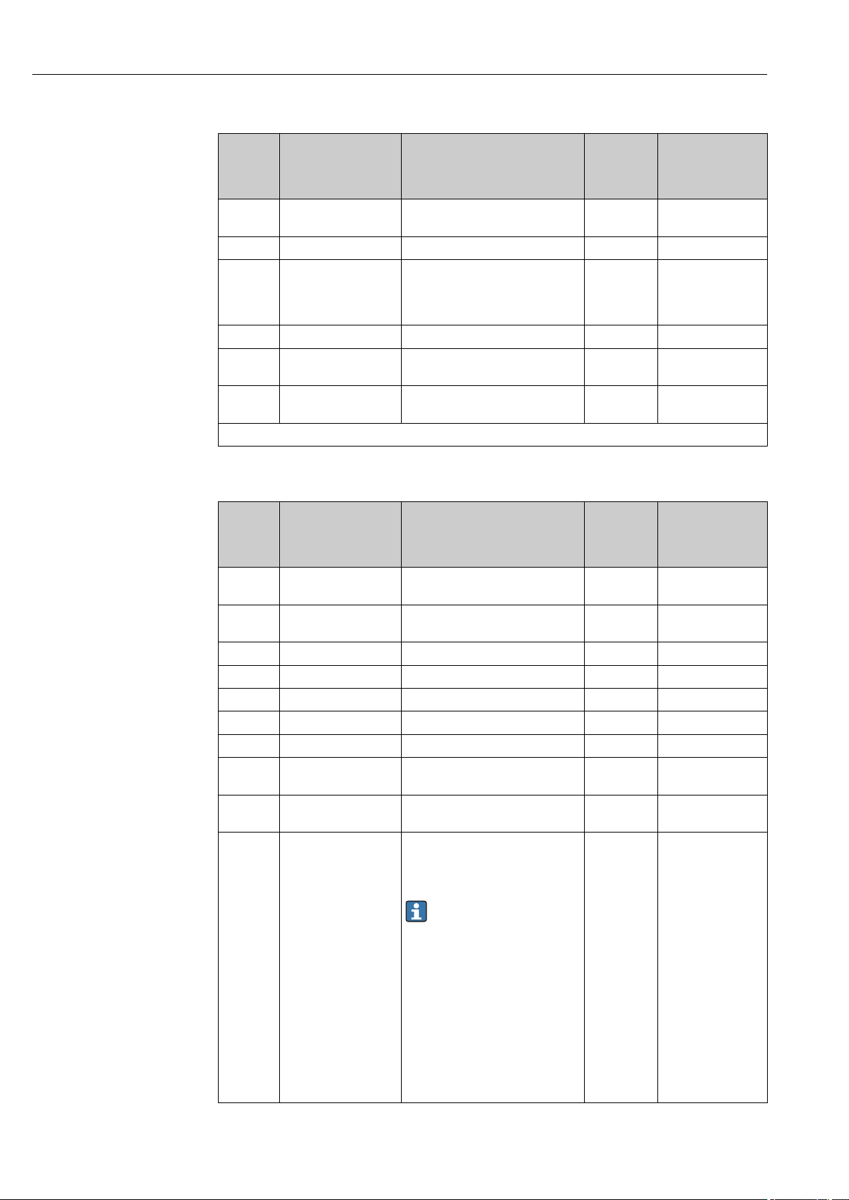
Diagnostics and troubleshooting Proline Promass I 100 Modbus RS485
Diagnostics for the configuration
Status
Diagnosti
c number
Short text Remedial measures
410 Data transfer 1. Check connection.
signal
from the
factory
from the factory
F Alarm
2. Retry data transfer.
411 Up-/download active Up-/download active, please wait C Warning
438 Dataset 1. Check data set file.
M Warning
2. Check device configuration.
3. Up- and download new
configuration.
453 Flow override Deactivate flow override. C Warning
484 Simulation failsafe
Deactivate simulation. C Alarm
mode
485 Simulation process
Deactivate simulation. C Warning
variable
*
Diagnostic behavior can be changed: "Adapting the diagnostic behavior" section ( 64)
Diagnostics for the process
Status
Diagnosti
c number
Short text Remedial measures
830 Ambient temperature Reduce the ambient temperature
around the sensor housing.
831 Ambient temperature Increase the ambient temperature
around the sensor housing.
832 Ambient temperature Reduce ambient temperature. S Warning
833 Ambient temperature Increase ambient temperature. S Warning
834 Process temperature Reduce process temperature. S Warning
835 Process temperature Increase process temperature. S Warning
843 Process limit Check process conditions. S Warning
862 Partly filled pipe 1. Check for gas in process.
2. Check detection limits.
910 Measuring tube does
not vibrate
1. Check electronics.
2. Inspect sensor.
912 Inhomogeneous Fluid is inhomogeneous, e.g. gas or
solid content!
1. Check process conditions.
2. Increase system pressure.
In particular with outgassing
media and/or increased gas
content, the following
measures are recommended
to increase system pressure:
• Install the instrument at
the outlet side of a pump.
• Install the instrument at
the lowest point of an
ascending pipeline.
• Install a flow restriction,
e.g. reducer or orifice plate,
downstream from the
instrument.
signal
from the
factory
from the factory
S Warning
S Warning
S Warning
F Alarm
S Warning
Diagnostic
behavior
Diagnostic
behavior
*
*
*
*
*
66 Endress+Hauser
Page 67
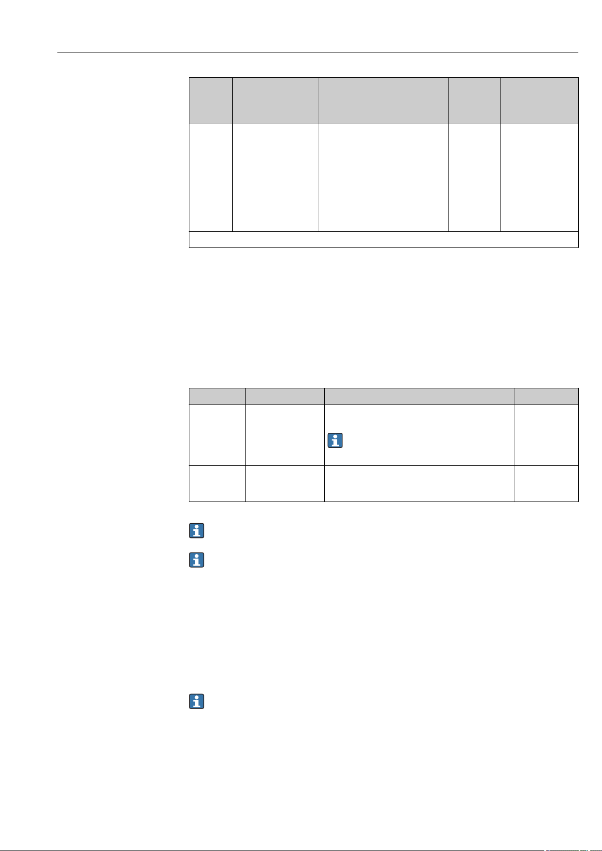
Proline Promass I 100 Modbus RS485 Diagnostics and troubleshooting
Status
Diagnosti
c number
913 Inhomogeneous Oscillation amplitude limit!
*
Diagnostic behavior can be changed: "Adapting the diagnostic behavior" section ( 64)
Short text Remedial measures
The fluid properties do not allow a
precise measurement.
Cause: Process fluid is very
inhomogeneous (gas or solid
content)
1. Check process conditions.
2. Increase voltage.
3. Check main electronic module or
sensor.
signal
from the
factory
S Alarm*
Diagnostic
behavior
from the factory
12.7 Pending diagnostic events
The Diagnostics menu allows the user to view the current diagnostic event and the
previous diagnostic event separately.
Navigation path
• "Diagnostics" menu Actual diagnostics
• "Diagnostics" menu Previous diagnostics
Parameter overview with brief description
Parameter Prerequisite Description Display
Actual
diagnostics
Previous
diagnostics
1 diagnostic event
has occurred
2 diagnostic events
have already
occurred
Displays the current diagnostic event along with the
diagnostic information.
If two or more messages occur simultaneously,
the message with the highest priority is shown
on the display.
Displays the diagnostic event that occurred prior to
the current diagnostic event along with the
diagnostic information.
Diagnostic code,
short message
Diagnostic code,
short message
To call up the measures to rectify a diagnostic event:
Via "FieldCare" operating tool ( 63)
Other diagnostic events that are pending can be viewed in the Diagnostic list
submenu ( 67)
12.8 Diagnostic list
In the Diagnostic list submenu, up to 5 currently pending diagnostic events can be
displayed along with the related diagnostic information. If more than 5 diagnostic events
are pending, the events with the highest priority are shown on the display.
Navigation path
"Diagnostics" menu Diagnostic list
To call up the measures to rectify a diagnostic event:
Via "FieldCare" operating tool ( 63)
Endress+Hauser 67
Page 68
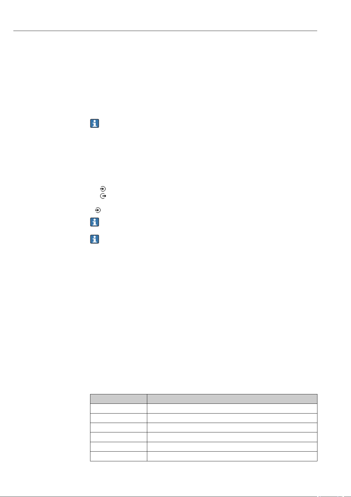
Diagnostics and troubleshooting Proline Promass I 100 Modbus RS485
12.9 Event logbook
12.9.1 Event history
A chronological overview of the event messages that have occurred is provided in the
events list which contains a maximum of 20 message entries. This list can be displayed via
FieldCare if necessary.
Navigation path
Event list: F Tool box Additional functions
For information on the event list, see the FieldCare user interface ( 38)
This event history includes entries for:
• Diagnostic events ( 65)
• Information events ( 68)
In addition to the operation time of its occurrence and possible troubleshooting measures,
each event is also assigned a symbol that indicates whether the event has occurred or is
ended:
• Diagnostics event
: Event has occurred
–
– : Event has ended
• Information event
: Event has occurred
To call up the measures to rectify a diagnostic event:
Via "FieldCare" operating tool ( 63)
For filtering the displayed event messages ( 68)
12.9.2 Filtering the event logbook
Using the Filter options parameter, you can define which category of event messages is
displayed in the Events list submenu.
Navigation path
"Diagnostics" menu Event logbook Filter options
Filter categories
• All
• Failure (F)
• Function check (C)
• Out of specification (S)
• Maintenance required (M)
• Information (I)
12.9.3 Overview of information events
Unlike a diagnostic event, an information event is displayed in the event logbook only and
not in the diagnostic list.
Information event Event text
I1000 -------- (device ok)
I1089 Power on
I1090 Configuration reset
I1091 Configuration changed
I1110 Write protection switch changed
I1111 Density adjust. error
68 Endress+Hauser
Page 69
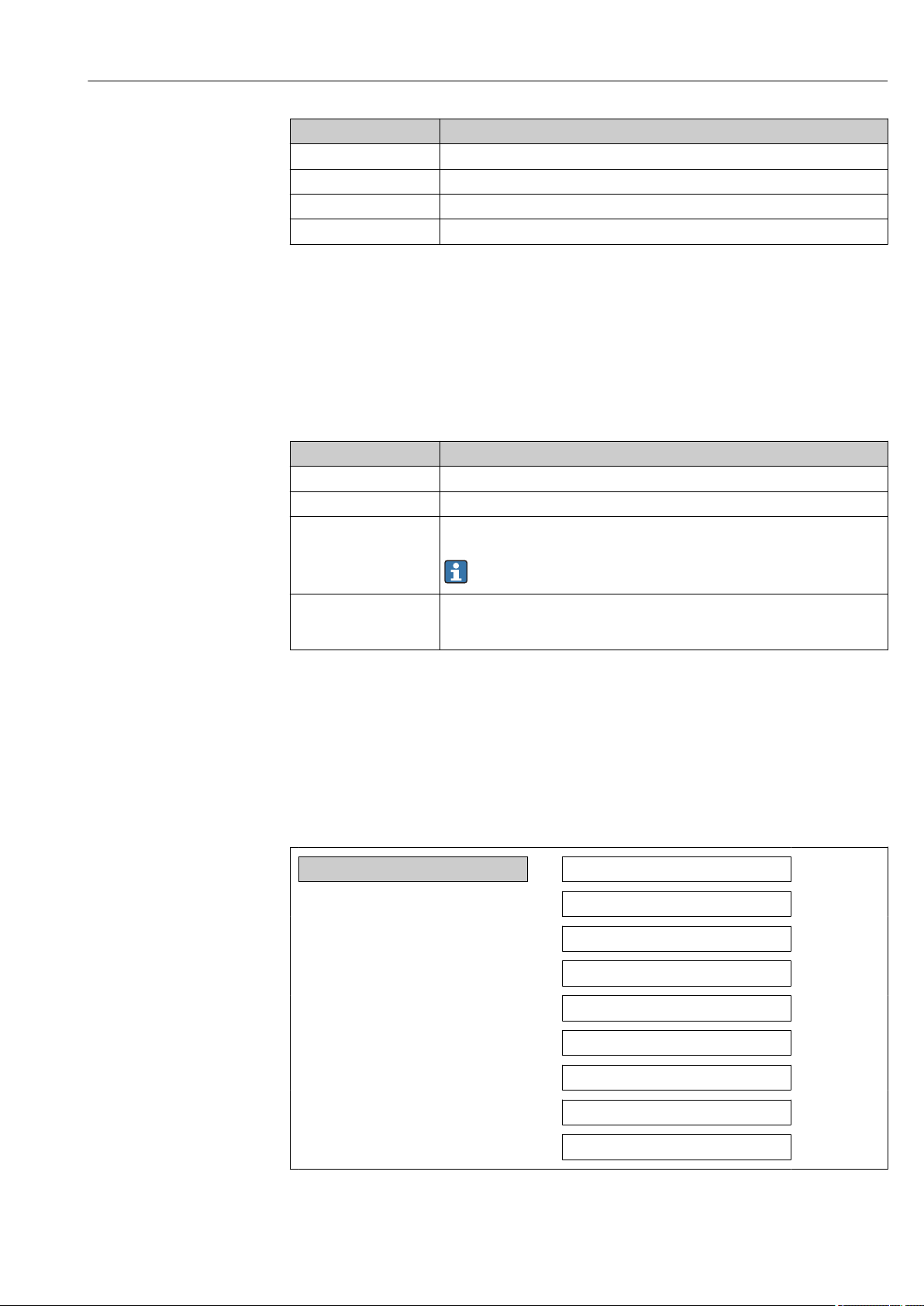
Proline Promass I 100 Modbus RS485 Diagnostics and troubleshooting
Information event Event text
I1151 History reset
I1209 Density adjustment OK
I1221 Zero point adjust failure
I1222 Zero point adjustment OK
12.10 Resetting the measuring device
Using the Device reset parameter it is possible to reset the entire device configuration or
some of the configuration to a defined state.
Navigation path
"Diagnostics" menu Device reset Device reset
Function scope of the "Device reset" parameter
Options Description
Cancel The user exists the parameter and no action is performed.
To factory defaults Every parameter is reset to its factory setting.
To delivery settings Every parameter for which a customized default setting was ordered is reset to that
customized value; all other parameters are reset to their factory setting.
This option is not visible if no customized settings were ordered.
Restart device Restarting the device resets every parameter whose data are saved in the volatile
memory (RAM) to the parameter's factory setting (e.g. measured value data). The
device configuration remains unchanged.
12.11 Device information
The Device information submenu contains all the parameters that display different
information for identifying the device.
Navigation path
"Diagnostics" menu Device information
Structure of the submenu
Device information
Device tag
Serial number
Firmware version
Device name
Order code
Extended order code 1
( 51)
Extended order code 2
Extended order code 3
ENP version
Endress+Hauser 69
Page 70
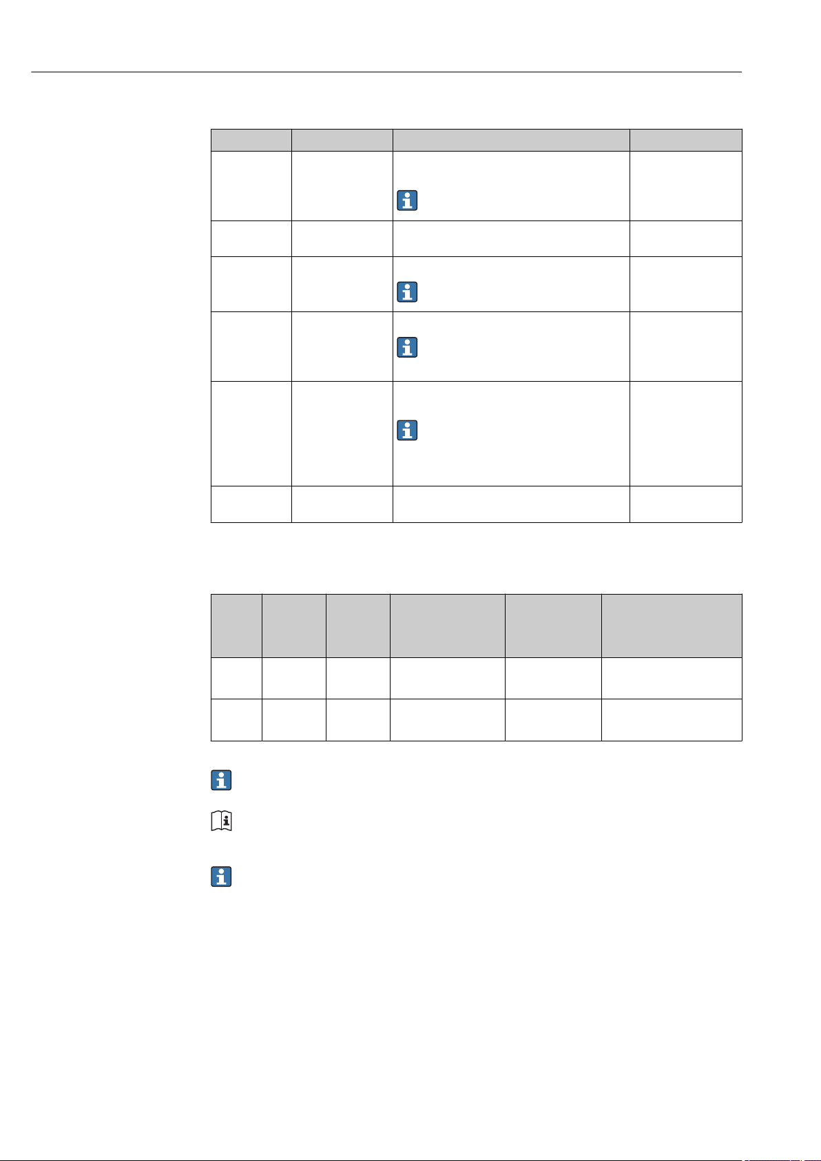
Diagnostics and troubleshooting Proline Promass I 100 Modbus RS485
Parameter overview with brief description
Parameter Prerequisite Description Display
Serial number - Displays the serial number of the measuring
device.
The number can be found on the
nameplate of the sensor and transmitter.
Firmware
version
Device name - Displays the name of the transmitter.
Order code - Displays the device order code.
Extended order
code 1-3
ENP version - Displays the version of the electronic nameplate. Character string in
- Displays the device firmware version installed. Character string in
The name can be found on the nameplate
of the transmitter.
The order code can be found on the
nameplate of the sensor and transmitter in
the "Order code" field.
Depending on the
length of the
extended order
code, the code is
divided into a
maximum of 3
parameters.
Displays the 1st, 2nd or 3rd part of the extended
order code.
The extended order code can also be found
on the nameplate of the sensor and
transmitter in the "Ext. ord. cd." field.
Max. 11-digit
character string
comprising letters
and numbers
the format xx.yy.zz
Promass 100
Character string
composed of letters,
numbers and certain
punctuation marks
Character string
the format xx.yy.zz
12.12 Firmware history
Release
date
04.2013 01.02.00 Option 74 Update Operating
06.2012 01.01.00 Option 78 Original firmware Operating
Firmware
version
Order code
for
"Firmware
version"
Firmware changes Documentation
type
Instructions
Instructions
Documentation
BA01058D/06/DE/02.13
BA01058D/06/EN/02.13
BA01058D/06/DE/01.12
BA01058D/06/EN/01.12
Flashing the firmware to the current version or to the previous version is possible via
the service interface (CDI) .
For the compatibility of the firmware version with the previous version, the installed
device description files and operating tools, observe the information about the device
in the "Manufacturer's information" document.
The manufacturer's information is available:
• In the Download Area of the Endress+Hauser Internet site: www.endress.com
Download
• Specify the following details:
– Product root, e.g. 8E1B
– Text search: Manufacturer's information
– Search range: documentation
70 Endress+Hauser
Page 71

Proline Promass I 100 Modbus RS485 Maintenance
13 Maintenance
13.1 Maintenance tasks
No special maintenance work is required.
13.1.1 Exterior cleaning
When cleaning the exterior of measuring devices, always use cleaning agents that do not
attack the surface of the housing or the seals.
13.1.2 Interior cleaning
Observe the following points for CIP and SIP cleaning:
• Use only cleaning agents to which the process-wetted materials are adequately resistant.
• Observe the maximum permitted medium temperature for the measuring device
( 86).
Observe the following points for cleaning with pigs:
Observe the inside diameter of the measuring tube and process connection.
13.2 Measuring and test equipment
Endress+Hauser offers a wide variety of measuring and test equipment, such as W@M or
device tests.
Your Endress+Hauser Sales Center can provide detailed information on the services.
For a list of some of the measuring and test equipment, refer to the "Accessories"
chapter of the "Technical Information" document for the device.
13.3 Endress+Hauser services
Endress+Hauser offers a wide variety of services for maintenance such as recalibration,
maintenance service or device tests.
Your Endress+Hauser Sales Center can provide detailed information on the services.
Endress+Hauser 71
Page 72

Repair Proline Promass I 100 Modbus RS485
14 Repair
14.1 General notes
Repair and conversion concept
The Endress+Hauser repair and conversion concept provides for the following:
• The measuring devices have a modular design.
• Spare parts are grouped into logical kits with the associated Installation Instructions.
• Repairs are carried out by Endress+Hauser Service or by correspondingly trained
customers.
• Certified devices can be converted into other certified devices by Endress+Hauser Service
or at the factory only.
Notes for repair and conversion
For repair and modification of a measuring device, observe the following notes:
• Use only original Endress+Hauser spare parts.
• Carry out the repair according to the Installation Instructions.
• Observe the applicable standards, federal/national regulations, Ex documentation (XA)
and certificates.
• Document every repair and each conversion and enter them into the W@M life cycle
management database.
14.2 Spare parts
W@M Device Viewer (
All the spare parts for the measuring device, along with the order code, are listed here and
can be ordered. If available, users can also download the associated Installation
Instructions.
Measuring device serial number:
• Is located on the nameplate of the device.
• Can be read out via the Serial number parameter in the Device information
submenu ( 69).
www.endress.com/deviceviewer):
14.3 Endress+Hauser services
Contact your Endress+Hauser Sales Center for information on services and spare
parts.
14.4 Return
The measuring device must be returned if repairs or a factory calibration are required, or if
the wrong measuring device has been ordered or delivered. According to legal regulations,
Endress+Hauser, as an ISO-certified company, is required to follow certain procedures
when handling returned products that are in contact with medium.
To ensure swift, safe and professional device returns, please read the return procedures
and conditions on the Endress+Hauser website at
www.services.endress.com/return-material
14.5 Disposal
14.5.1 Removing the measuring device
1. Switch off the device.
72 Endress+Hauser
Page 73

Proline Promass I 100 Modbus RS485 Repair
2. WARNING! Danger to persons from process conditions. Beware of hazardous process
conditions such as pressure in the measuring device, high temperatures or aggressive
fluids.
Carry out the mounting and connection steps from the chapters "Mounting the
measuring device" and "Connecting the measuring device" in the logically reverse
sequence. Observe the safety instructions.
14.5.2 Disposing of the measuring device
WARNING
Danger to personnel and environment from fluids that are hazardous to health.
Ensure that the measuring device and all cavities are free of fluid residues that are
‣
hazardous to health or the environment, e.g. substances that have permeated into
crevices or diffused through plastic.
Observe the following notes during disposal:
• Observe valid federal/national regulations.
• Ensure proper separation and reuse of the device components.
Endress+Hauser 73
Page 74
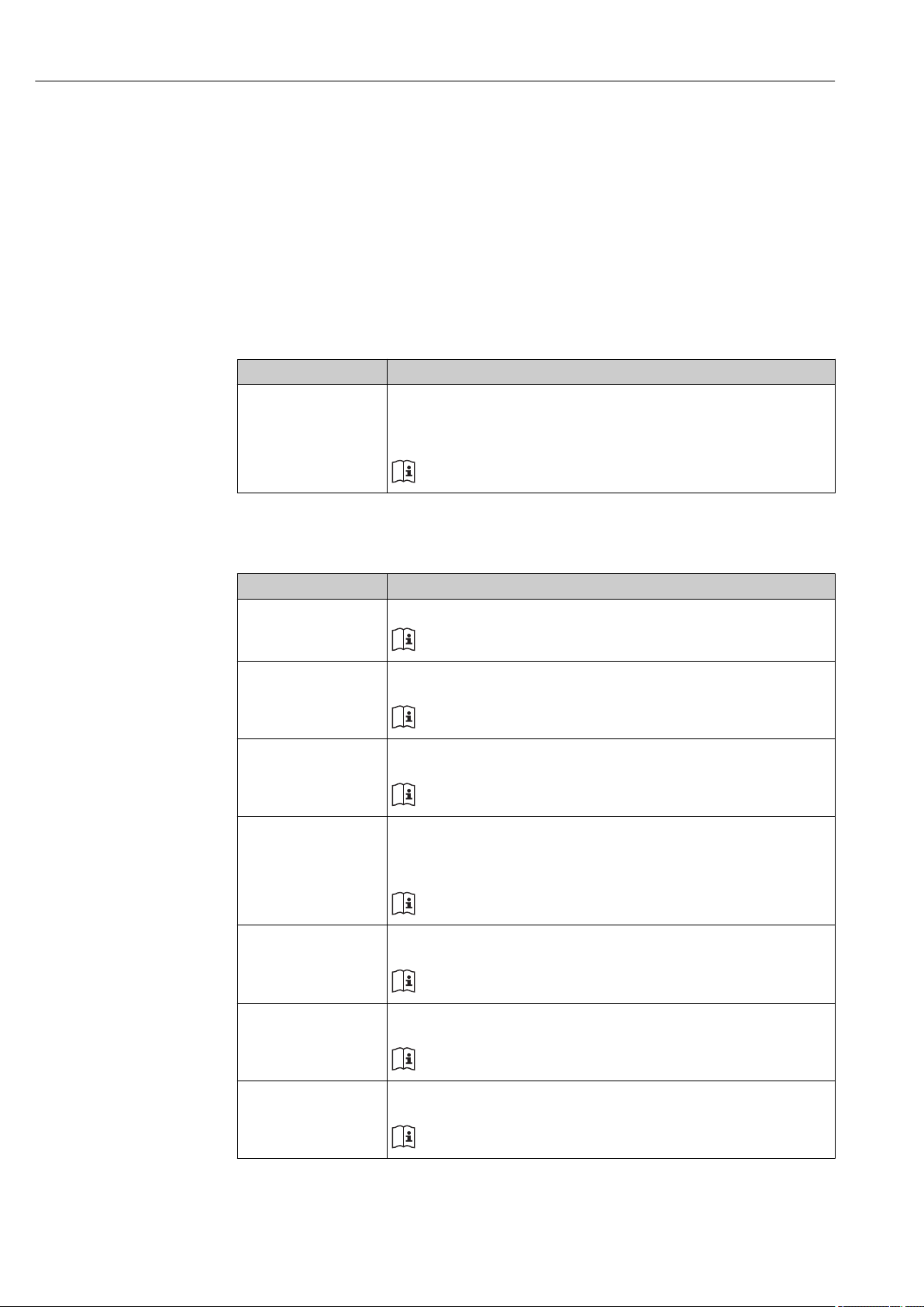
Accessories Proline Promass I 100 Modbus RS485
15 Accessories
Various accessories, which can be ordered with the device or subsequently from Endress
+Hauser, are available for the device. Detailed information on the order code in question is
available from your local Endress+Hauser sales center or on the product page of the
Endress+Hauser website:
15.1 Device-specific accessories
15.1.1 For the sensor
Accessories Description
Heating jacket Is used to stabilize the temperature of the fluids in the sensor.
www.endress.com.
Water, water vapor and other non-corrosive liquids are permitted for use as fluids.
If using oil as a heating medium, please consult with Endress+Hauser.
Heating jackets cannot be used with sensors fitted with a rupture disk.
For details, see Operating Instructions BA00099D
15.2 Communication-specific accessories
Accessories Description
Commubox FXA195
HART
Commubox FXA291 Connects Endress+Hauser field devices with a CDI interface (= Endress+Hauser
HART Loop Converter
HMX50
Wireless HART adapter
SWA70
Fieldgate FXA320 Gateway for the remote monitoring of connected 4-20 mA measuring devices via a
Fieldgate FXA520 Gateway for the remote diagnostics and remote configuration of connected HART
Field Xpert SFX100 Compact, flexible and robust industry handheld terminal for remote configuration
For intrinsically safe HART communication with FieldCare via the USB interface.
For details, see "Technical Information" TI00404F
Common Data Interface) and the USB port of a computer or laptop.
For details, see "Technical Information" TI00405C
Is used to evaluate and convert dynamic HART process variables to analog current
signals or limit values.
For details, see "Technical Information" TI00429F and Operating Instructions
BA00371F
Is used for the wireless connection of field devices.
The WirelessHART adapter can be easily integrated into field devices and existing
infrastructures, offers data protection and transmission safety and can be operated
in parallel with other wireless networks with minimum cabling complexity.
For details, see Operating Instructions BA00061S
Web browser.
For details, see "Technical Information" TI00025S and Operating Instructions
BA00053S
measuring devices via a Web browser.
For details, see "Technical Information" TI00025S and Operating Instructions
BA00051S
and for obtaining measured values via the HART current output (4-20 mA).
For details, see Operating Instructions BA00060S
74 Endress+Hauser
Page 75
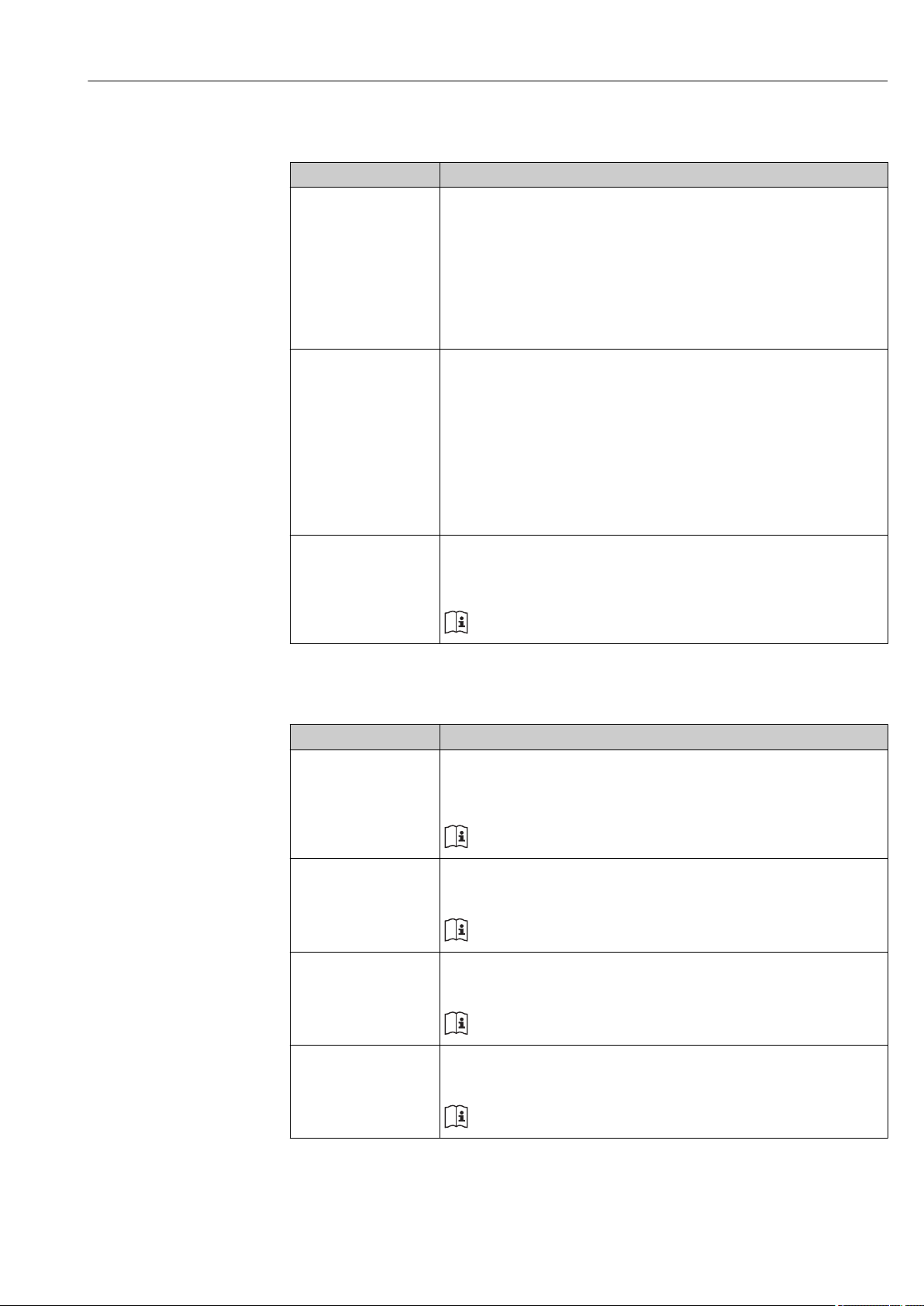
Proline Promass I 100 Modbus RS485 Accessories
15.3 Service-specific accessories
Accessories Description
Applicator Software for selecting and sizing Endress+Hauser measuring devices:
• Calculation of all the necessary data for identifying the optimum flowmeter: e.g.
nominal diameter, pressure loss, accuracy or process connections.
• Graphic illustration of the calculation results
Administration, documentation and access to all project-related data and
parameters over the entire life cycle of a project.
Applicator is available:
• Via the Internet: https://wapps.endress.com/applicator
• On CD-ROM for local PC installation.
W@M Life cycle management for your plant
W@M supports you with a wide range of software applications over the entire
process: from planning and procurement, to the installation, commissioning and
operation of the measuring devices. All the relevant device information, such as
the device status, spare parts and device-specific documentation, is available for
every device over the entire life cycle.
The application already contains the data of your Endress+Hauser device. Endress
+Hauser also takes care of maintaining and updating the data records.
W@M is available:
• Via the Internet: www.endress.com/lifecyclemanagement
• On CD-ROM for local PC installation.
FieldCare FDT-based plant asset management tool from Endress+Hauser.
It can configure all smart field units in your system and helps you manage them. By
using the status information, it is also a simple but effective way of checking their
status and condition.
For details, see Operating Instructions BA00027S and BA00059S
15.4 System components
Accessories Description
Memograph M graphic
display recorder
Cerabar M The pressure transmitter for measuring the absolute and gauge pressure of gases,
Cerabar S The pressure transmitter for measuring the absolute and gauge pressure of gases,
iTEMP The temperature transmitters can be used in all applications and are suitable for
The Memograph M graphic data manager provides information on all the relevant
measured variables. Measured values are recorded correctly, limit values are
monitored and measuring points analyzed. The data are stored in the 256 MB
internal memory and also on a SD card or USB stick.
For details, see "Technical Information" TI00133R and Operating Instructions
BA00247R
steam and liquids. It can be used to read in the operating pressure value via
Modbus RS485 or EtherNet/IP.
For details, see "Technical Information" TI00426P, TI00436P and Operating
Instructions BA00200P, BA00382P
steam and liquids. It can be used to read in the operating pressure value via
Modbus RS485 or EtherNet/IP.
For details, see "Technical Information" TI00383P and Operating Instructions
BA00271P
the measurement of gases, steam and liquids. They can be used to read in the
medium temperature via analog or digital communication.
For details, see "Fields of Activity", FA00006T
Endress+Hauser 75
Page 76

Technical data Proline Promass I 100 Modbus RS485
16 Technical data
16.1 Application
The measuring device is suitable for flow measurement of liquids and gases only.
Depending on the version ordered, the measuring device can also measure potentially
explosive, flammable, poisonous and oxidizing media.
To ensure that the device remains in proper operating condition for its service life, use the
measuring device only for media against which the process-wetted materials are
adequately resistant.
16.2 Function and system design
Measuring principle Mass flow measurement based on the Coriolis measuring principle
Measuring system The device consists of a transmitter and a sensor. If a device with Modbus RS485
intrinsically safe is ordered, the Safety Barrier Promass 100 is part of the scope of supply
and must be implemented to operate the device.
One device version is available: compact version, transmitter and sensor form a mechanical
unit.
For information on the structure of the device ( 10)
16.3 Input
Measured variable Direct measured variables
• Mass flow
• Density
• Temperature
• Viscosity
Calculated measured variables
• Volume flow
• Corrected volume flow
• Reference density
Measuring range Measuring ranges for liquids
DN Measuring range full scale values
[mm] [in] [kg/h] [lb/min]
8 ³⁄₈ 0 to 2 000 0 to 73.5
15 ½ 0 to 6 500 0 to 238
15 FB ½ FB 0 to 18 000 0 to 660
25 1 0 to 18 000 0 to 660
25 FB 1 FB 0 to 45 000 0 to 1 650
40 1½ 0 to 45 000 0 to 1 650
40 FB 1½ FB 0 to 70 000 0 to 2 570
min(F)
to
max(F)
76 Endress+Hauser
Page 77
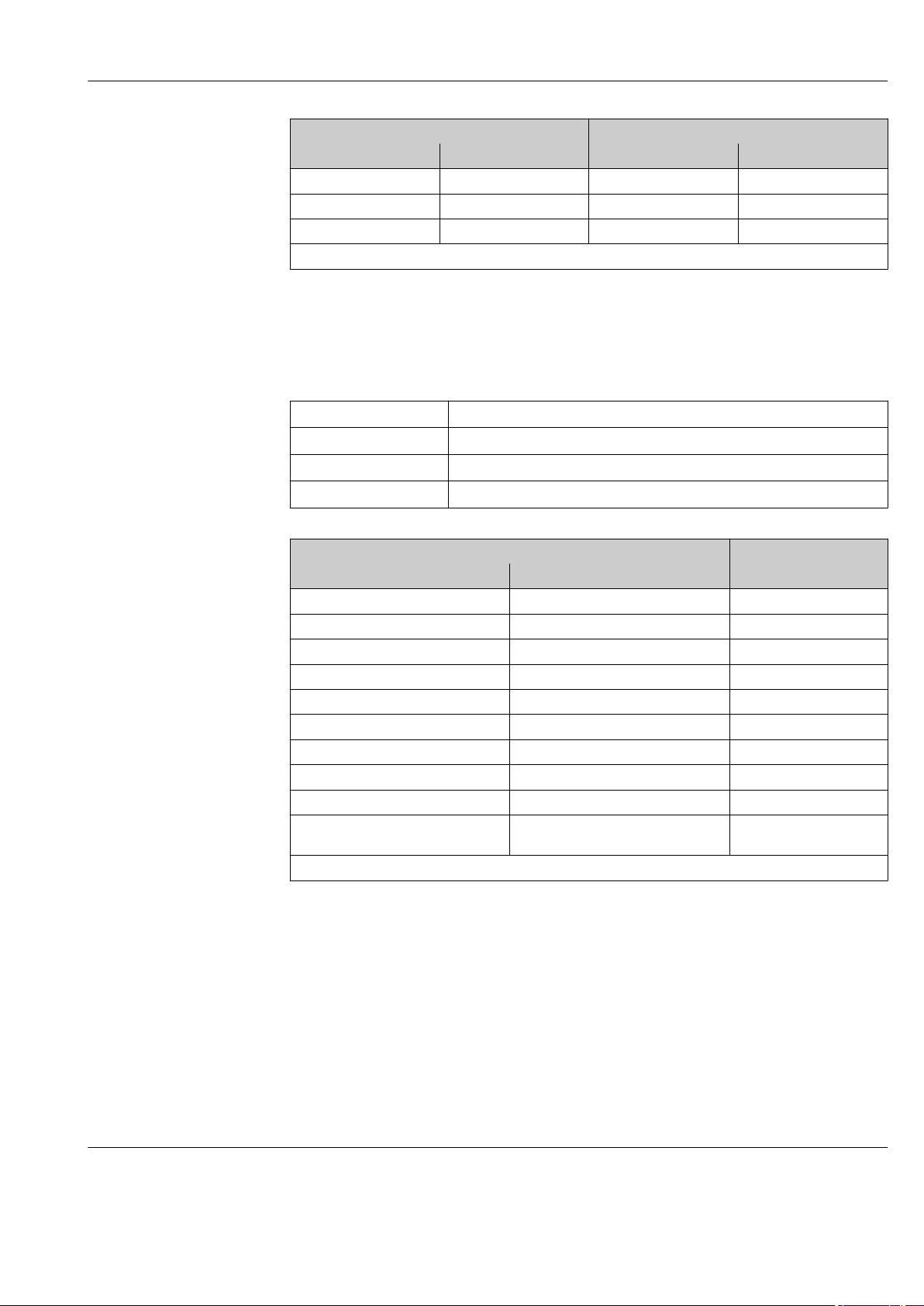
Proline Promass I 100 Modbus RS485 Technical data
DN Measuring range full scale values
[mm] [in] [kg/h] [lb/min]
50 2 0 to 70 000 0 to 2 570
50 FB 2 FB 0 to 180 000 0 to 6 600
80 3 0 to 180 000 0 to 6 600
FB = Full bore
min(F)
to
Measuring ranges for gases
The full scale values depend on the density of the gas and can be calculated with the
formula below:
=
max(G)
max(G)
max(F)
<
max(G)
ρ
G
FB = Full bore
· ρG : x
max(F)
Maximum full scale value for gas [kg/h]
Maximum full scale value for liquid [kg/h]
max(F)
[mm] [in] [kg/m3]
8 ³⁄₈ 60
15 ½ 80
15 FB ½ FB 90
25 1 90
25 FB 1 FB 90
40 1½ 90
40 FB 1½ FB 90
50 2 90
50 FB 2 FB 110
80 3 155
can never be greater than
max(G)
Gas density in [kg/m³] at operating conditions
DN x
max(F)
110
max(F)
Calculation example for gas
• Sensor: Promass I, DN 50
• Gas: Air with a density of 60.3 kg/m³ (at 20 °C and 50 bar)
• Measuring range (liquid):70 000 kg/h
• x = 90 kg/m³ (for Promass I, DN 50)
Maximum possible full scale value:
max(G)
=
· ρG : x = 70 000 kg/h · 60.3 kg/m³ : 90 kg/m³ = 46 900 kg/h
max(F)
Recommended measuring range
"Flow limit" section ( 86)
Operable flow range Over 1000 : 1.
Flow rates above the preset full scale value are not overridden by the electronics unit, with
the result that the totalizer values are registered correctly.
Endress+Hauser 77
Page 78
Technical data Proline Promass I 100 Modbus RS485
Input signal Fieldbuses
To increase the accuracy of certain measured variables or to calculate the corrected volume
flow for gases, the automation system can continuously write different measured values to
the measuring device via Modbus RS485, EtherNet/IP or HART input:
• Process pressure or medium temperature to increase accuracy (e.g. external values from
Cerabar M, Cerabar S or iTEMP)
• Reference density for calculating the corrected volume flow
16.4 Output
Output signal Modbus RS485
Physical interface In accordance with EIA/TIA-485-A standard
Terminating resistor • For device version used in non-hazardous areas or Zone 2/Div. 2: integrated
and can be activated via DIP switches on the transmitter electronics module
• For device version used in intrinsically safe areas: integrated and can be
activated via DIP switches on the Safety Barrier Promass 100
Signal on alarm Depending on the interface, failure information is displayed as follows:
Modbus RS485
Failure mode Choose from:
• NaN value instead of current value
• Last valid value
Operating tool
Plain text display With information on cause and remedial measures
Light emitting diodes (LED)
Status information Status indicated by various light emitting diodes
The following information is displayed depending on the device version:
• Supply voltage active
• Data transmission active
• Device alarm/error has occurred
Ex connection data These values only apply for the following device version:
Order code for "Output", option M: Modbus RS485, for use in intrinsically safe areas
78 Endress+Hauser
Page 79
Proline Promass I 100 Modbus RS485 Technical data
Transmitter
Intrinsically safe values
Order code for
"Approvals"
• Option BM: ATEX II2G + IECEx Z1 Ex ia, II2D Ex tb
• Option BO: ATEX II1/2G + IECEx Z0/Z1 Ex ia, II2D
• Option BQ: ATEX II1/2G + IECEx Z0/Z1 Ex ia
• Option BU: ATEX II2G + IECEx Z1 Ex ia
• Option C2: CSA C/US IS Cl. I, II, III Div. 1
• Option 85: ATEX II2G + IECEx Z1 Ex ia + CSA C/US
IS Cl. I, II, III Div. 1
*
The gas group depends on the sensor and nominal diameter.
For an overview and for information on the interdependencies between the gas group - sensor - nominal
diameter, see the "Safety Instructions" (XA) document for the measuring device
Supply voltage Signal transmission
20 (L-) 10 (L+) 62 (A) 72 (B)
Terminal numbers
Ui =16.24 V
Ii =623 mA
Pi =2.45 W
Li = 0 µH
Ci =6 nF
Low flow cut off The switch points for low flow cut off are user-selectable.
Galvanic isolation The following connections are galvanically isolated from each other:
• Outputs
• Power supply
Protocol-specific data Modbus RS485
Protocol Modbus Applications Protocol Specification V1.1
Device type Slave
Slave address range 1 to 247
Broadcast address range 0
Function codes • 03: Read holding register
• 04: Read input register
• 06: Write single registers
• 08: Diagnostics
• 16: Write multiple registers
• 23: Read/write multiple registers
Broadcast messages Supported by the following function codes:
• 06: Write single registers
• 16: Write multiple registers
• 23: Read/write multiple registers
Supported baud rate • 1 200 BAUD
• 2 400 BAUD
• 4 800 BAUD
• 9 600 BAUD
• 19 200 BAUD
• 38 400 BAUD
• 57 600 BAUD
• 115 200 BAUD
Data transfer mode • ASCII
• RTU
Data access Each device parameter can be accessed via Modbus RS485.
For Modbus register information ( 93)
Endress+Hauser 79
Page 80
Technical data Proline Promass I 100 Modbus RS485
16.5 Power supply
Terminal assignment ( 26)
Pin assignment, device plug ( 28)
Supply voltage Transmitter
• For device version with all communication types except Modbus RS485 intrinsically safe:
DC20 to 30 V
• For device version with Modbus RS485100 intrinsically safe: power supply via Safety
Barrier Promass 100
The power unit must be tested to ensure it meets safety requirements (e.g. PELV, SELV).
Safety Barrier Promass 100
DC20 to 30 V
Power consumption Transmitter
Option M: Modbus RS485, for use in non-hazardous areas and
Zone 2/Div. 2
Option M: Modbus RS485, for use in intrinsically safe areas 2.45 W
Safety Barrier Promass 100
Option M: Modbus RS485, for use in intrinsically safe areas 4.8 W
Current consumption Transmitter
Option M: Modbus RS485, for use in non-hazardous areas and
Zone 2/Div. 2
Option M: Modbus RS485, for use in intrinsically safe areas 145 mA 16 A (< 0.4 ms)
Order code for
"Output"
Order code for
"Output"
Order code for
"Output"
Maximum
Power consumption
3.5 W
Maximum
Power consumption
Maximum
Current consumption
90 mA 10 A (< 0.8 ms)
Maximum
switch-on current
Safety Barrier Promass 100
Order code for
"Output"
Option M: Modbus RS485, for use in intrinsically safe areas 230 mA 10 A (< 0.8 ms)
Maximum
Current consumption
Maximum
switch-on current
Power supply failure • Totalizers stop at the last value measured.
• Depending on the device version, the configuration is retained in the device memory or
in the plug-in memory (HistoROM DAT).
• Error messages (incl. total operated hours) are stored.
Electrical connection ( 29)
80 Endress+Hauser
Page 81

Proline Promass I 100 Modbus RS485 Technical data
Potential equalization No special measures for potential equalization are required.
Terminals Transmitter
Spring terminals for wire cross-sections0.5 to 2.5 mm2 (20 to 14 AWG)
Safety Barrier Promass 100
Plug-in screw terminals for wire cross-sections0.5 to 2.5 mm2 (20 to 14 AWG)
Cable entries Transmitter
• Cable gland: M20 × 1.5 with cable 6 to 12 mm (0.24 to 0.47 in)
• Thread for cable entry:
– NPT ½"
– G ½"
– M20
Cable specification ( 24)
16.6 Performance characteristics
Reference operating conditions
Maximum measured error o.r. = of reading; 1 g/cm³ = 1 kg/l; T = medium temperature
• Error limits based on ISO 11631
• Water with +15 to +45 °C (+59 to +113 °F) at2 to 6 bar (29 to 87 psi)
• Specifications as per calibration protocol
• Accuracy based on accredited calibration rigs that are traced to ISO 17025.
To obtain measured errors, use the Applicator sizing tool ( 93)
Base accuracy
Mass flow and volume flow (liquids)
±0.10 %
Mass flow (gases)
±0.50 % o.r.
Design fundamentals ( 84)
Density (liquids)
• Reference conditions:±0.0005 g/cm³
• Standard density calibration:±0.02 g/cm³
(valid over the entire temperature range and density range )
• Wide-range density specification (order code for "Application package", option EF "Special
density and concentration" or EH " Special density and viscosity"): ±0.004 g/cm³ (valid
range for special density calibration: 0 to 2 g/cm³, +10 to +80 °C (+50 to +176 °F))
Temperature
±0.5 °C ± 0.005 · T °C (±0.9 °F ± 0.003 · (T – 32) °F)
Endress+Hauser 81
Page 82
Technical data Proline Promass I 100 Modbus RS485
E [%]
Q [%]
0 5 10 15 20 25 30 35 40 45 50 60 6555
0
0.5
1.0
1.5
2.0
2.5
70 75 80 85 90 95 100
Zero point stability
DN Zero point stability
[mm] [in] [kg/h] [lb/min]
8 ³⁄₈ 0.150 0.0055
15 ½ 0.488 0.0179
15 FB ½ FB 1.350 0.0496
25 1 1.350 0.0496
25 FB 1 FB 3.375 0.124
40 1½ 3.375 0.124
40 FB 1 ½ FB 5.25 0.193
50 2 5.25 0.193
50 FB 2 FB 13.5 0.496
80 3 13.5 0.496
FB = Full bore
Example for max. measured error
E Error: Maximum measured error as % o.r. (example)
Q Flow rate as %
Design fundamentals ( 84)
Flow values
Flow values as turndown parameter depending on nominal diameter.
SI units
A0016709
DN 1:1 1:10 1:20 1:50 1:100 1:500
[mm]
[kg/h] [kg/h] [kg/h] [kg/h] [kg/h] [kg/h]
8 2 000 200 100 40 20 4
15 6 500 650 325 130 65 13
15 FB 18 000 1 800 900 360 180 36
25 18 000 1 800 900 360 180 36
82 Endress+Hauser
25 FB 45 000 4 500 2 250 900 450 90
40 45 000 4 500 2 250 900 450 90
40 FB 70 000 7 000 3 500 1 400 700 140
Page 83
Proline Promass I 100 Modbus RS485 Technical data
DN 1:1 1:10 1:20 1:50 1:100 1:500
[mm]
50 70 000 7 000 3 500 1 400 700 140
50 FB 180 000 18 000 9 000 3 600 1 800 360
80 180 000 18 000 9 000 3 600 1 800 360
FB = Full bore
[kg/h] [kg/h] [kg/h] [kg/h] [kg/h] [kg/h]
US units
DN 1:1 1:10 1:20 1:50 1:100 1:500
[inch] [lb/min] [lb/min] [lb/min] [lb/min] [lb/min] [lb/min]
³⁄₈ 73.5 7.35 3.675 1.47 0.735 0.147
½ 238 23.8 11.9 4.76 2.38 476
½ FB 660 66 33 13.2 6.6 1.32
1 660 66 33 13.2 6.6 1.32
1 FB 1 650 165 825 33 16.5 3.3
1½ 1 650 165 825 33 16.5 3.3
1½ FB 2 570 257 1'285 51.4 25.7 5.14
2 2 570 257 1'285 51.4 25.7 5.14
2 FB 6 600 660 330 132 66 13.2
3 6 600 660 330 132 66 13.2
FB = Full bore
Repeatability o.r. = of reading; 1 g/cm3 = 1 kg/l; T = medium temperature
Mass flow and volume flow (liquids)
±0.05 % o.r.
Mass flow (gases)
±0.25 % o.r.
Design fundamentals ( 84)
Density (liquids)
±0.00025 g/cm
3
Temperature
±0.25 °C ± 0.0025 · T °C (±0.45 °F ± 0.0015 · (T–32) °F)
Response time • The response time depends on the configuration (damping).
• Response time in the event of erratic changes in the measured variable (only mass flow):
after 100 ms 95 % of the full scale value
Influence of medium temperature
Mass flow and volume flow
When there is a difference between the temperature for zero point adjustment and the
process temperature, the typical measured error of the sensor is ±0.0002 % of the full
scale value/°C (±0.0001 % of the full scale value/°F).
Density
When there is a difference between the density calibration temperature and the process
temperature, the typical measured error of the sensor is
±0.0001 g/cm3 /°C (±0.00005 g/cm3 /°F). Field density calibration is possible.
Endress+Hauser 83
Page 84
Technical data Proline Promass I 100 Modbus RS485
[kg/m ]
3
-40
0
-80
40 80 120 160 200 240 280 320
-50
0
50
100 150
0
2
4
6
8
10
14
12
16
1
2
[°C]
[°F]
Wide-range density specification (special density calibration)
If the process temperature is outside the valid range ( 81) the measured error is
±0.0001 g/cm3 /°C (±0.00005 g/cm3 /°F)
Influence of medium pressure
A0016614
1 Field density calibration, for example at +20 °C (+68 °F)
2 Special density calibration
Temperature
±0.005 · T °C (± 0.005 · (T – 32) °F)
The table below shows the effect on accuracy of mass flow due to a difference between
calibration pressure and process pressure.
o.r. = of reading
DN [% o.r./bar] [% o.r./psi]
[mm] [in]
8 ³⁄₈ no influence no influence
15 ½ no influence no influence
15 FB ½ FB –0.003 –0.0002
25 1 –0.003 –0.0002
25 FB 1 FB no influence no influence
40 1½ no influence no influence
40 FB 1½ FB no influence no influence
50 2 no influence no influence
50 FB 2 FB –0.003 –0.0002
80 3 no influence no influence
FB = Full bore
Design fundamentals o.r. = of reading, o.f.s. = of full scale value
84 Endress+Hauser
Page 85

Proline Promass I 100 Modbus RS485 Technical data
Dependent on the flow:
• Flow in % o.f.s. ≥ (zero point stability : base accuracy in % o.r.) · 100
– Maximum measured error in % o.r.: ±base accuracy in % o.r.
– Repeatability in % o.r.: ±½ · base accuracy in % o.r.
• Flow in % o.f.s. < (zero point stability : base accuracy in % o.r.) · 100
– Maximum measured error in % o.r.: ± (zero point stability : measured value) · 100
– Repeatability in % o.r.: ±½ · (zero point stability : measured value) · 100
Base accuracy for [% o.r.]
Mass flow, liquids 0.1
Volume flow, liquids 0.1
Mass flow, gases 0.5
16.7 Installation
"Mounting requirements" ( 17)
16.8 Environment
Ambient temperature range
Storage temperature –40 to +80 °C (–40 to +176 °F), preferably at +20 °C (+68 °F)
Climate class DIN EN 60068-2-38 (test Z/AD)
Degree of protection Transmitter and sensor
Shock resistance As per IEC/EN 60068-2-31
Vibration resistance Acceleration up to 1 g, 10 to 150 Hz, based on IEC/EN 60068-2-6
Interior cleaning • SIP cleaning
( 19)
• As standard: IP66/67, type 4X enclosure
• With the order code for "Sensor options", option CM: IP69K can also be ordered
• When housing is open: IP20, type 1 enclosure
Safety Barrier Promass 100
IP20
• CIP cleaning
Electromagnetic compatibility (EMC)
Endress+Hauser 85
• As per IEC/EN 61326 and NAMUR Recommendation 21 (NE 21)
• Complies with emission limits for industry as per EN 55011 (Class A)
Details are provided in the Declaration of Conformity.
Page 86
Technical data Proline Promass I 100 Modbus RS485
16.9 Process
Medium temperature range Sensor
–50 to +150 °C (–58 to +302 °F)
Seals
No internal seals
Medium density 0 to 5 000 kg/m3 (0 to 312 lb/cf)
Pressure-temperature ratings
Secondary containment pressure range
An overview of the material load diagrams (pressure/temperature diagrams) for the
process connections is provided in the "Technical Information" document.
The sensor housing is filled with dry nitrogen and protects the electronics and mechanics
inside.
DN Secondary containment
pressure range
[mm] [in] [bar] [psi] [bar] [psi]
8 ³⁄₈ 40 580 220 3190
15 ½ 40 580 220 3190
15 FB ½ FB 40 580 235 3405
25 1 40 580 235 3405
25 FB 1 FB 40 580 220 3190
40 1½ 40 580 220 3190
40 FB 1 ½ FB 40 580 235 3405
50 2 40 580 235 3405
50 FB 2 FB 40 580 460 6670
80 3 40 580 460 6670
FB = Full bore
Burst pressure
If there is a risk of measuring tube failure due to process characteristics, e.g. with
corrosive process fluids, we recommend the use of sensors whose secondary
containment is equipped with special pressure monitoring connections (order code for
"Purge connection", option CH). With the help of these connections, the fluid collected
in the secondary containment can be bled off in the event of tube failure. This is
especially important in high-pressure gas applications. These connections can also be
used for gas purging (gas detection).
Dimensions:
Flow limit Select the nominal diameter by optimizing between the required flow range and
permissible pressure loss.
For an overview of the measuring range full scale values, see the "Measuring range"
section ( 76)
86 Endress+Hauser
Page 87

Proline Promass I 100 Modbus RS485 Technical data
• The minimum recommended full scale value is approx. 1/20 of the maximum full scale
value
• In most applications, 20 to 50 % of the maximum full scale value can be considered ideal
• Select a lower full scale value for abrasive substances (such as liquids with entrained
solids): flow velocity <1 m/s (<3 ft/s).
• For gas measurement the following rules apply:
– The flow velocity in the measuring tubes should not exceed half the sonic velocity
(0.5 Mach).
– The maximum mass flow depends on the density of the gas: formula ( 77)
Pressure loss
To calculate the pressure loss, use the Applicator sizing tool ( 93)
Endress+Hauser 87
Page 88
Technical data Proline Promass I 100 Modbus RS485
16.10 Mechanical construction
Design, dimensions
For the dimensions and installation lengths of the device, see the "Technical
Information" document, "Mechanical construction" section
Weight Compact version
Weight in SI units
All values (weight) refer to devices with EN/DIN PN 40 flanges. Weight information in
[kg].
FB = Full bore
DN
[mm]
8 11
15 13
15 FB 19
25 20
25 FB 39
40 40
40 FB 65
50 67
50 FB 118
80 122
Weight [kg]
Weight in US units
All values (weight) refer to devices with EN/DIN PN 40 flanges. Weight information in
[lbs].
DN
[in]
3/8 24
½ 29
½ FB 42
1 44
1 FB 86
1½ 88
1½ FB 143
2 148
2 FB 260
3 269
FB = Full bore
Weight [lbs]
Safety Barrier Promass 100
49 g (25 ounce)
88 Endress+Hauser
Page 89
Proline Promass I 100 Modbus RS485 Technical data
Materials Transmitter housing
• Order code for "Housing", option A "Compact, coated alu":
Coated aluminum AlSi10Mg
• Order code for "Housing", option B "Compact, hygienic, stainless":
Hygienic version, stainless steel 1.4301 (304)
• Order code for "Housing", option C "Ultra compact hygienic, stainless":
Hygienic version, stainless steel 1.4301 (304)
Cable entries
Order code for "Housing", option A "Compact, coated alu"
The various cable entries are suitable for hazardous and non-hazardous areas.
Electrical connection Material
Cable gland M20 × 1.5 Nickel-plated brass
Thread G ½", via adapter
Thread NPT ½", via adapter
Order code for "Housing", option B "Compact, hygienic, stainless"
The various cable entries are suitable for hazardous and non-hazardous areas.
Electrical connection Material
Cable gland M20 × 1.5 Stainless steel 1.4404 (316L)
Thread G ½", via adapter
Thread NPT ½", via adapter
Device plug
Electrical connection Material
Plug M12x1 • Socket: Stainless steel 1.4404 (316L)
• Contact housing: Polyamide
• Contacts: Gold-plated brass
Sensor housing
• Acid and alkali-resistant outer surface
• Stainless steel 1.4301 (304)
Measuring tubes
Grade 9 titanium
Surface quality:
• Not polished
• Ra
• Ra
= 0.8 µm (32 µin)
max
= 0.4 µm (16 µin)
max
Endress+Hauser 89
Page 90

Technical data Proline Promass I 100 Modbus RS485
Process connections
• Flanges according to EN 1092-1 (DIN 2501) / according to ASME B16.5/ according to
JIS:
– Stainless steel 1.4301 (304),
– Wetted parts: Grade 2 titanium
• All other process connections:
Grade 2 titanium
List of all available process connections ( 90)
Seals
Welded process connections without internal seals
Safety Barrier Promass 100
Housing: Polyamide
Process connections • Flanges:
– EN 1092-1 (DIN 2501)
– ASME B16.5
– JIS B2220
• Tri-Clamp (OD tubes)
• Clamp (eccentric) :
Tri-Clamp
• Threaded hygienic connection:
– DIN 11851
– SMS 1145
– ISO 2853
– DIN 11864-1 Form A
• Flange:
DIN 11864-2 Form A
For information on the materials of the process connections ( 89)
16.11 Operability
Remote operation Service interface (CDI)
Operation of the measuring device with the service interface (CDI) via:
"FieldCare" operating tool with COM DTM "CDI Communication FXA291" via Commubox
FXA291
Languages Can be operated in the following languages:
Via "FieldCare" operating tool:
English, German, French, Spanish, Italian, Chinese, Japanese
16.12 Certificates and approvals
CE mark The measuring system is in conformity with the statutory requirements of the applicable
EC Directives. These are listed in the corresponding EC Declaration of Conformity along
with the standards applied.
Endress+Hauser confirms successful testing of the device by affixing to it the CE mark.
90 Endress+Hauser
Page 91

Proline Promass I 100 Modbus RS485 Technical data
C-Tick symbol The measuring system meets the EMC requirements of the "Australian Communications
and Media Authority (ACMA)".
Ex approval The devices are certified for use in hazardous areas and the relevant safety instructions are
provided in the separate "Safety Instructions" (XA) document. Reference is made to this
document on the nameplate.
Hygienic compatibility • 3A approval
• EHEDG-tested
Modbus RS485 certification The measuring device meets all the requirements of the MODBUS/TCP conformity test and
has the "MODBUS/TCP Conformance Test Policy, Version 2.0". The measuring device has
successfully passed all the test procedures carried out and is certified by the
“MODBUS/TCP Conformance Test Laboratory” of the University of Michigan.
Pressure Equipment Directive
Other standards and guidelines
• With the PED/G1/x (x = category) marking on the sensor nameplate, Endress+Hauser
confirms compliance with the "Essential Safety Requirements" specified in Annex I of the
Pressure Equipment Directive 97/23/EC.
• Devices not bearing this marking (PED) are designed and manufactured according to
good engineering practice. They meet the requirements of Art.3 Section 3 of the
Pressure Equipment Directive 97/23/EC. The range of application is indicated in tables 6
to 9 in Annex II of the Pressure Equipment Directive.
• EN 60529
Degrees of protection provided by enclosures (IP code)
• IEC/EN 60068-2-6
Environmental influences: Test procedure - Test Fc: vibrate (sinusoidal).
• IEC/EN 60068-2-31
Environmental influences: Test procedure - Test Ec: shocks due to rough handling,
primarily for devices.
• EN 61010-1
Safety requirements for electrical equipment for measurement, control and laboratory
use
• IEC/EN 61326
Emission in accordance with Class A requirements. Electromagnetic compatibility (EMC
requirements)
• NAMUR NE 21
Electromagnetic compatibility (EMC) of industrial process and laboratory control
equipment
• NAMUR NE 32
Data retention in the event of a power failure in field and control instruments with
microprocessors
• NAMUR NE 43
Standardization of the signal level for the breakdown information of digital transmitters
with analog output signal.
• NAMUR NE 53
Software of field devices and signal-processing devices with digital electronics
• NAMUR NE 80
The application of the pressure equipment directive to process control devices
• NAMUR NE 105
Specifications for integrating fieldbus devices in engineering tools for field devices
Endress+Hauser 91
Page 92

Technical data Proline Promass I 100 Modbus RS485
• NAMUR NE 107
Self-monitoring and diagnosis of field devices
• NAMUR NE 131
Requirements for field devices for standard applications
• NAMUR NE 132
Coriolis mass meter
16.13 Application packages
Many different application packages are available to enhance the functionality of the
device. Such packages might be needed to address safety aspects or specific application
requirements.
The application packages can be ordered from Endress+Hauser either directly with the
device or subsequently. Detailed information on the order code in question is available
from your local Endress+Hauser sales center or on the product page of the Endress+Hauser
website:
www.endress.com.
Heartbeat Technology
Concentration
Package Description
Heartbeat Verification
+Monitoring
Package Description
Concentration
measurement and special
density
Heartbeat Monitoring:
Continuously supplies monitoring data, which are characteristic of the measuring
principle, for an external condition monitoring system. This makes it possible to:
• Draw conclusions - using these data and other information - about the impact
the measuring application has on the measuring performance over time.
• Schedule servicing in time.
• Monitor the product quality, e.g. gas pockets.
Heartbeat Verification:
Makes it possible to check the device functionality on demand when the device is
installed, without having to interrupt the process.
• Access via onsite operation or other interfaces (requires no on-site presence).
• Ideal solution for recurring device checks (SIL).
• End-to-end, traceable documentation of the verification results and verification
report.
• Extension of calibration intervals.
Calculation and outputting of fluid concentrations
Many applications use density as a key measured value for monitoring quality or
controlling processes. The device measures the density of the fluid as standard and
makes this value available to the control system.
The "Special Density" application package offers high-precision density
measurement over a wide density and temperature range particularly for
applications subject to varying process conditions.
With the help of the "Concentration Measurement" application package, the
measured density is used to calculate other process parameters:
• Temperature-compensated density (reference density).
• Percentage mass of the individual substances in a two-phase fluid.
(Concentration in %).
• Fluid concentration is output with special units (°Brix, °Baumé, °API, etc.) for
standard applications.
The measured values are output via the digital and analog outputs of the device.
92 Endress+Hauser
Page 93
Proline Promass I 100 Modbus RS485 Technical data
Viscosity
Package Description
Viscosity measurement In-line and real-time viscosity measurement
Promass I with the "Viscosity" application package also measures the real-time
viscosity of the fluid directly in the process, in addition to measuring the mass
flow/volume flow/ temperature and density.
The following viscosity measurements are performed on liquids:
• Dynamic viscosity
• Kinematic viscosity
• Temperature-compensated viscosity (kinematic and dynamic) in relation to the
reference temperature
Viscosity measurement can be used for Newtonian and non-Newtonian
applications and supplies accurate measured data irrespective of the flow, even
under difficult conditions.
16.14 Accessories
Overview of accessories available for order ( 74)
16.15 Documentation
The following document types are available:
• On the CD-ROM supplied with the device
• In the Download Area of the Endress+Hauser Internet site: www.endress.com
Download
Standard documentation
Supplementary devicedependent documentation
Communication Document type Documentation code
- - - - Brief Operating Instructions KA01117D
- - - - Technical Information TI01035D
Document type Contents Documentation code
Safety Instructions ATEX/IECEx Ex i XA00159D
ATEX/IECEx Ex nA XA01029D
cCSAus IS XA00160D
Special documentation Information on the Pressure Equipment
Directive
Special documentation Modbus RS485 Register Information SD00154D
Special documentation Concentration Measurement SD01152D
Special documentation Viscosity Measurement SD01151D
Special documentation Heartbeat Technology SD01153D
Installation Instructions Specified for each individual accessory
SD00142D
( 74)
Overview of accessories available
for order ( 74)
Endress+Hauser 93
Page 94
Appendix Proline Promass I 100 Modbus RS485
17 Appendix
17.1 Overview of the operating menu
The following table provides an overview of the entire operating menu structure with
menus and parameters. The page reference indicates where a description of the parameter
can be found in the manual.
Display/operat.
Locking status
Setup
( 36)
( 57)
Operation
Control totalizer 1 to 3
Preset value 1 to 3
Reset all totalizers
( 43)
System units
Mass flow unit
Mass unit
Volume flow unit
Volume unit
Corrected volume flow
unit
( 59)
( 59)
( 59)
( 59)
( 43)
Corrected volume unit
Density unit
Reference density unit
Temperature unit
Pressure unit
Medium selection
Select medium
Select gas type
Reference sound velocity
Temperature coefficient
sound velocity
Pressure compensation
Pressure value
External pressure
( 46)
94 Endress+Hauser
Page 95
Proline Promass I 100 Modbus RS485 Appendix
Communication
Bus address
Baud rate
Data transfer mode
Parity
Byte order
Assign diagnostic
behavior
Failure mode
Low flow cut off
Assign process variable
On value low flow cutoff
Off value low flow cutoff
Pressure shock
suppression
( 47)
( 49)
Partially filled pipe
detection
Assign process variable
Low value partial filled
pipe detection
High value partial filled
pipe detection
Response time part.
filled pipe detect.
Advanced setup
Enter access code
Device tag
( 50)
( 51)
( 51)
Calculated values
Corrected volume flow
calculation
External reference
density
( 51)
Fixed reference density
Reference temperature
Linear expansion
coefficient
Endress+Hauser 95
Page 96
Appendix Proline Promass I 100 Modbus RS485
Square expansion
coefficient
Sensor adjustment
Installation direction
Totalizer 1 to 3
Assign process variable
Mass unit
Volume unit
Corrected volume unit
Totalizer operation mode
Failure mode
Viscosity
( 52)
Zero point adjustment
Zero point adjustment
control
Progress
( 53)
( 93)
Temperature
compensation
Calculation model
Reference temperature
Compensation coefficient
X1
Compensation coefficient
X1
Dynamic viscosity
Dynamic viscosity unit
User dynamic viscosity
text
User dynamic viscosity
factor
User dynamic viscosity
offset
Kinematic viscosity
Kinematic viscosity unit
User kinematic viscosity
text
96 Endress+Hauser
Page 97
Proline Promass I 100 Modbus RS485 Appendix
User kinematic viscosity
factor
User kinematic viscosity
offset
Diagnostics
Actual diagnostics
Concentration
Concentration unit
User concentration text
User concentration factor
User concentration offset
A0 to A4
B1 to B3
Heartbeat Setup
Progress
Heartbeat Monitoring
Activate monitoring
( 67)
( 93)
( 93)
Timestamp
Previous diagnostics
Timestamp
Operating time from
restart
Operating time
Diagnostic list
Diagnostics 1 to 5
Timestamp
Event logbook
Filter options
Device information
Device tag
Serial number
( 67)
( 68)
( 68)
( 69)
( 51)
Firmware version
Device name
Endress+Hauser 97
Page 98
Appendix Proline Promass I 100 Modbus RS485
Order code
Extended order
code1 to 3
ENP version
Measured values
( 57)
Process variables
Mass flow
Volume flow
Corrected volume flow
Density
Reference density
Temperature
Pressure value
Dynamic viscosity
Kinematic viscosity
Temp. compensated
dynamic viscosity
Concentration
( 57)
( 93)
( 93)
( 93)
( 93)
Simulation
Assign simulation
process variable
Value process variable
Simulation device alarm
Heartbeat
Target mass flow
Carrier mass flow
Totalizer
Totalizer value1 to 3
Totalizer overflow1 to 3
( 54)
( 93)
Performing verification
Year
Month
( 53)
Day
98 Endress+Hauser
Page 99
Proline Promass I 100 Modbus RS485 Appendix
Hour
AM/PM
Minute
Start verification
Progress
Status
Expert
Locking status
Access status tooling
Verification results
Date/time
Verification ID
Operating time
Overall result
Sensor
Sensor integrity
Sensor electronic module
I/O module
Monitoring results
Device reset
( 36)
( 69)
( 57)
( 55)
Enter access code
System
Diagnostic behavior
Alarm delay
Assign behavior of
diagnostic no. 044
Assign behavior of
diagnostic no. 46
Assign behavior of
diagnostic no. 144
Assign behavior of
diagnostic no. 192
Assign behavior of
diagnostic no. 274
( 64)
Endress+Hauser 99
Page 100
Appendix Proline Promass I 100 Modbus RS485
Assign behavior of
diagnostic no. 392
Assign behavior of
diagnostic no. 592
Assign behavior of
diagnostic no. 832
Assign behavior of
diagnostic no. 833
Assign behavior of
diagnostic no. 834
Assign behavior of
diagnostic no. 835
Assign behavior of
diagnostic no. 912
Assign behavior of
diagnostic no. 913
Sensor
Assign behavior of
diagnostic no. 944
Assign behavior of
diagnostic no. 992
Management
Device reset
Activate SW option
SW option overview
Permanent storage
Device tag
( 57)
Measured values
( 57)
Process variables
Mass flow
Volume flow
( 57)
Corrected volume flow
Density
Reference density
Temperature
Pressure value
Dynamic viscosity
( 93)
100 Endress+Hauser
 Loading...