

Page 1
K
e
e
p
c
o
v
e
r
h
t
i
g
t
w
h
i
l
e
S
p
a
n
n
u
n
g
ö
f
f
n
e
n
N
i
c
h
t
u
n
t
e
r
c
i
r
c
u
i
t
s
a
r
e
a
l
i
v
e
BA01540D/06/EN/01.16
71303227
Valid as of version
01.00.zz (Device firmware)
Products Solutions Services
Operating Instructions
Proline Promass F 500
Modbus RS485
Coriolis flowmeter
Page 2

• Make sure the document is stored in a safe place such that it is always available when
working on or with the device.
• To avoid danger to individuals or the facility, read the "Basic safety instructions" section
carefully, as well as all other safety instructions in the document that are specific to
working procedures.
• The manufacturer reserves the right to modify technical data without prior notice. Your
Endress+Hauser Sales Center will supply you with current information and updates to
these instructions.
2 Endress+Hauser
Page 3

Table of contents
Table of contents
1 Document information .............. 6
1.1 Document function ..................... 6
1.2 Symbols used .......................... 6
1.2.1 Safety symbols .................. 6
1.2.2 Electrical symbols ................ 6
1.2.3 Communication symbols ........... 6
1.2.4 Tool symbols .................... 7
1.2.5 Symbols for certain types of
information .................... 7
1.2.6 Symbols in graphics ............... 7
1.3 Documentation ........................ 8
1.3.1 Standard documentation ........... 8
1.3.2 Supplementary device-dependent
documentation .................. 8
1.4 Registered trademarks ................... 9
2 Basic safety instructions ........... 10
2.1 Requirements for personnel .............. 10
2.2 Designated use ....................... 10
2.3 Workplace safety ...................... 11
2.4 Operational safety ..................... 11
2.5 Product safety ........................ 11
2.6 IT security ........................... 12
2.7 Device-specific IT security ................ 12
2.7.1 Protecting access via hardware write
protection ..................... 12
2.7.2 Protecting access via a password .... 12
2.7.3 Access via fieldbus ............... 13
2.7.4 Access via Web server ............ 13
3 Product description ................ 14
3.1 Product design ........................ 14
3.1.1 Proline 500 – digital ............. 14
3.1.2 Proline 500 .................... 15
4 Incoming acceptance and product
identification ..................... 16
4.1 Incoming acceptance ................... 16
4.2 Product identification ................... 17
4.2.1 Transmitter nameplate ........... 17
4.2.2 Sensor nameplate ............... 19
4.2.3 Symbols on measuring device ...... 20
5 Storage and transport ............. 21
5.1 Storage conditions ..................... 21
5.2 Transporting the product ................ 21
5.2.1 Measuring devices without lifting
lugs ......................... 21
5.2.2 Measuring devices with lifting lugs .. 22
5.2.3 Transporting with a fork lift ........ 22
5.3 Packaging disposal ..................... 22
6 Installation ....................... 22
6.1 Installation conditions .................. 22
6.1.1 Mounting position ............... 22
6.1.2 Requirements from environment and
process ....................... 25
6.1.3 Special mounting instructions ...... 28
6.2 Mounting the measuring device ........... 31
6.2.1 Required tools .................. 31
6.2.2 Preparing the measuring device ..... 31
6.2.3 Mounting the measuring device ..... 31
6.2.4 Mounting the transmitter housing:
Proline 500 – digital ............. 32
6.2.5 Mounting the transmitter housing:
Proline 500 .................... 33
6.2.6 Turning the transmitter housing:
Proline 500 .................... 34
6.2.7 Turning the display module: Proline
500 ......................... 35
6.3 Post-installation check .................. 36
7 Electrical connection .............. 37
7.1 Connection conditions .................. 37
7.1.1 Required tools .................. 37
7.1.2 Requirements for connecting cable ... 37
7.1.3 Terminal assignment ............. 40
7.1.4 Preparing the measuring device ..... 41
7.2 Connecting the measuring device: Proline
500 – digital ......................... 42
7.2.1 Connecting the connecting cable .... 42
7.2.2 Connecting the signal cable and the
supply voltage cable ............. 47
7.3 Connecting the measuring device: Proline
500 ................................ 49
7.3.1 Connecting the connecting cable .... 49
7.3.2 Connecting the signal cable and the
supply voltage cable ............. 53
7.4 Ensure potential equalization ............. 55
7.4.1 Requirements .................. 55
7.5 Special connection instructions ............ 55
7.5.1 Connection examples ............. 55
7.6 Hardware settings ..................... 59
7.6.1 Setting the device address ......... 59
7.6.2 Enabling the terminating resistor .... 60
7.7 Ensuring the degree of protection .......... 61
7.8 Post-connection check .................. 62
8 Operation options ................. 63
8.1 Overview of operation options ............ 63
8.2 Structure and function of the operating
menu .............................. 64
8.2.1 Structure of the operating menu .... 64
8.2.2 Operating philosophy ............ 65
Endress+Hauser 3
Page 4

Table of contents
8.3 Access to the operating menu via the local
display ............................. 66
8.3.1 Operational display .............. 66
8.3.2 Navigation view ................ 68
8.3.3 Editing view ................... 70
8.3.4 Operating elements .............. 71
8.3.5 Opening the context menu ......... 72
8.3.6 Navigating and selecting from list ... 74
8.3.7 Calling the parameter directly ...... 74
8.3.8 Calling up help text .............. 75
8.3.9 Changing the parameters ......... 76
8.3.10 User roles and related access
authorization .................. 77
8.3.11 Disabling write protection via access
code ......................... 77
8.3.12 Enabling and disabling the keypad
lock ......................... 77
8.4 Access to the operating menu via the Web
browser ............................. 78
8.4.1 Function range ................. 78
8.4.2 Prerequisites ................... 78
8.4.3 Establishing a connection ......... 80
8.4.4 Logging on .................... 81
8.4.5 User interface .................. 82
8.4.6 Disabling the Web server .......... 83
8.4.7 Logging out .................... 83
8.5 Access to the operating menu via the
operating tool ........................ 83
8.5.1 Connecting the operating tool ...... 84
8.5.2 FieldCare ..................... 86
8.5.3 DeviceCare .................... 87
9 System integration ................ 89
9.1 Overview of device description files ......... 89
9.1.1 Current version data for the device ... 89
9.1.2 Operating tools ................. 89
9.2 Compatibility with earlier model ........... 89
9.3 Modbus RS485 information .............. 90
9.3.1 Function codes ................. 90
9.3.2 Register information ............. 91
9.3.3 Response time .................. 91
9.3.4 Modbus data map ............... 91
10 Commissioning .................... 93
10.1 Function check ....................... 93
10.2 Setting the operating language ............ 93
10.3 Configuring the measuring device .......... 93
10.3.1 Defining the tag name ............ 94
10.3.2 Setting the system units .......... 95
10.3.3 Configuring the communication
interface ...................... 96
10.3.4 Selecting and setting the medium ... 98
10.3.5 Displaying the I/O configuration .... 99
10.3.6 Configuring the current input ..... 100
10.3.7 Configuring the status input ...... 101
10.3.8 Configuring the current output .... 102
10.3.9 Configuring the pulse/frequency/
switch output ................. 105
10.3.10 Configuring the relay output ...... 114
10.3.11 Configuring the double pulse output 116
10.3.12 Configuring the local display ...... 117
10.3.13 Configuring the low flow cut off .... 120
10.3.14 Configuring the partial filled pipe
detection .................... 121
10.4 Advanced settings .................... 122
10.4.1 Calculated values ............... 123
10.4.2 Carrying out a sensor adjustment ... 124
10.4.3 Configuring the totalizer ......... 125
10.4.4 Carrying out additional display
configurations ................. 127
10.4.5 WLAN configuration ............ 130
10.4.6 Configuration management ....... 131
10.4.7 Using parameters for device
administration ................ 133
10.5 Simulation .......................... 134
10.6 Protecting settings from unauthorized
access ............................. 137
10.6.1 Write protection via access code ... 137
10.6.2 Write protection via write protection
switch ....................... 139
11 Operation ....................... 141
11.1 Reading the device locking status ......... 141
11.2 Adjusting the operating language ......... 141
11.3 Configuring the display ................ 141
11.4 Reading measured values ............... 141
11.4.1 "Measured variables" submenu ..... 142
11.4.2 "Totalizer" submenu ............. 143
11.4.3 "Input values" submenu .......... 144
11.4.4 Output values ................. 145
11.5 Adapting the measuring device to the process
conditions .......................... 148
11.6 Performing a totalizer reset ............. 148
11.6.1 Function scope of the "Control
Totalizer" parameter ............ 149
11.6.2 Function scope of the "Reset all
totalizers" parameter ............ 149
11.7 Showing data logging ................. 149
12 Diagnostics and troubleshooting .. 152
12.1 General troubleshooting ................ 152
12.2 Diagnostic information via light emitting
diodes ............................. 154
12.2.1 Transmitter ................... 154
12.2.2 Sensor connection housing ....... 156
12.3 Diagnostic information on local display ..... 158
12.3.1 Diagnostic message ............. 158
12.3.2 Calling up remedial measures ..... 160
12.4 Diagnostic information in the Web browser . 160
12.4.1 Diagnostic options .............. 160
12.4.2 Calling up remedy information .... 161
12.5 Diagnostic information in DeviceCare or
FieldCare ........................... 161
12.5.1 Diagnostic options .............. 161
12.5.2 Calling up remedy information .... 162
4 Endress+Hauser
Page 5

Table of contents
12.6 Diagnostic information via communication
interface ........................... 163
12.6.1 Reading out diagnostic information 163
12.6.2 Configuring error response mode ... 163
12.7 Adapting the diagnostic information ...... 163
12.7.1 Adapting the diagnostic behavior ... 163
12.8 Overview of diagnostic information ....... 164
12.9 Pending diagnostic events .............. 168
12.10 Diagnostic list ....................... 169
12.11 Event logbook ....................... 169
12.11.1 Event history .................. 169
12.11.2 Filtering the event logbook ....... 170
12.11.3 Overview of information events .... 170
12.12 Resetting the measuring device .......... 172
12.12.1 Function scope of the "Device reset"
parameter .................... 172
12.13 Device information ................... 172
12.14 Firmware history ..................... 174
13 Maintenance .................... 175
13.1 Maintenance tasks .................... 175
13.1.1 Exterior cleaning ............... 175
13.1.2 Interior cleaning ............... 175
13.2 Measuring and test equipment ........... 175
13.3 Endress+Hauser services ............... 175
16.12 Certificates and approvals .............. 206
16.13 Application packages .................. 208
16.14 Accessories ......................... 209
16.15 Supplementary documentation ........... 210
Index ................................. 212
14 Repairs .......................... 176
14.1 General notes ....................... 176
14.1.1 Repair and conversion concept ..... 176
14.1.2 Notes for repair and conversion .... 176
14.2 Spare parts ......................... 176
14.3 Endress+Hauser services ............... 176
14.4 Return ............................. 176
14.5 Disposal ........................... 177
14.5.1 Removing the measuring device .... 177
14.5.2 Disposing of the measuring device .. 177
15 Accessories ...................... 178
15.1 Device-specific accessories .............. 178
15.1.1 For the transmitter ............. 178
15.1.2 For the sensor ................. 179
15.2 Service-specific accessories .............. 179
15.3 System components ................... 179
16 Technical data ................... 181
16.1 Application ......................... 181
16.2 Function and system design ............. 181
16.3 Input .............................. 182
16.4 Output ............................ 185
16.5 Power supply ........................ 189
16.6 Performance characteristics ............. 190
16.7 Installation ......................... 195
16.8 Environment ........................ 195
16.9 Process ............................ 196
16.10 Mechanical construction ............... 198
16.11 Operability ......................... 202
Endress+Hauser 5
Page 6
Document information Proline Promass F 500 Modbus RS485
DANGER
WARNING
CAUTION
NOTICE
1 Document information
1.1 Document function
These Operating Instructions contain all the information that is required in various phases
of the life cycle of the device: from product identification, incoming acceptance and
storage, to mounting, connection, operation and commissioning through to
troubleshooting, maintenance and disposal.
1.2 Symbols used
1.2.1 Safety symbols
Symbol Meaning
DANGER!
This symbol alerts you to a dangerous situation. Failure to avoid this situation will
result in serious or fatal injury.
WARNING!
This symbol alerts you to a dangerous situation. Failure to avoid this situation can
result in serious or fatal injury.
CAUTION!
This symbol alerts you to a dangerous situation. Failure to avoid this situation can
result in minor or medium injury.
NOTE!
This symbol contains information on procedures and other facts which do not result in
personal injury.
1.2.2 Electrical symbols
Symbol Meaning
Direct current
Alternating current
Direct current and alternating current
Ground connection
A grounded terminal which, as far as the operator is concerned, is grounded via a
grounding system.
Protective ground connection
A terminal which must be connected to ground prior to establishing any other
connections.
Equipotential connection
A connection that has to be connected to the plant grounding system: This may be a
potential equalization line or a star grounding system depending on national or
company codes of practice.
1.2.3 Communication symbols
Symbol Meaning
Wireless Local Area Network (WLAN)
Communication via a wireless, local network.
Bluetooth
Wireless data transmission between devices over a short distance.
6 Endress+Hauser
Page 7
Proline Promass F 500 Modbus RS485 Document information
A
1.
1.
Symbol Meaning
LED
Light emitting diode is off.
LED
Light emitting diode is on.
LED
Light emitting diode is flashing.
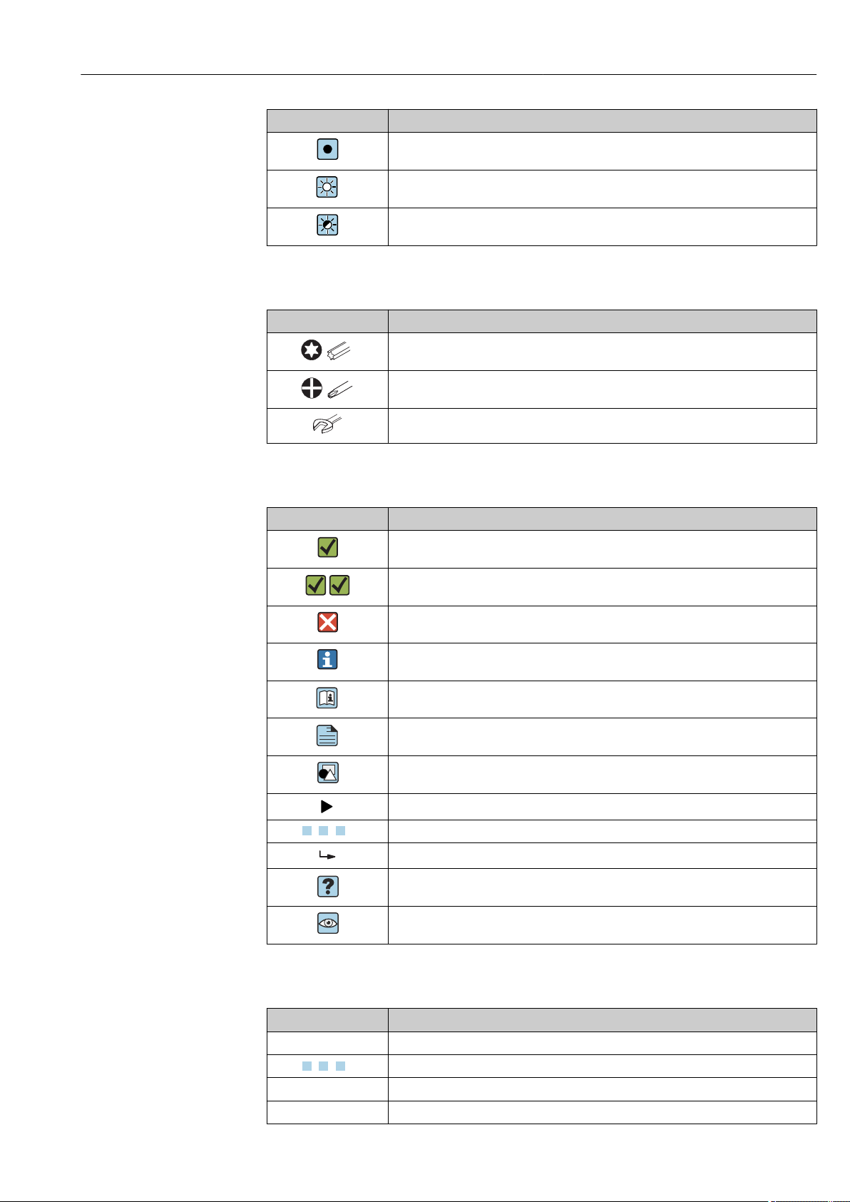
1.2.4 Tool symbols
Symbol Meaning
Torx screwdriver
Phillips head screwdriver
Open-ended wrench
1.2.5 Symbols for certain types of information
Symbol Meaning
Permitted
Procedures, processes or actions that are permitted.
Preferred
Procedures, processes or actions that are preferred.
Forbidden
Procedures, processes or actions that are forbidden.
Tip
Indicates additional information.
Reference to documentation
Reference to page
Reference to graphic
Notice or individual step to be observed
, 2., 3.… Series of steps
Result of a step
Help in the event of a problem
Visual inspection
1.2.6 Symbols in graphics
Symbol Meaning
1, 2, 3,... Item numbers
, 2., 3.… Series of steps
A, B, C, ... Views
A-A, B-B, C-C, ... Sections
Endress+Hauser 7
Page 8
Document information Proline Promass F 500 Modbus RS485
-
.
Symbol Meaning
Hazardous area
Safe area (non-hazardous area)
Flow direction
1.3 Documentation
For an overview of the scope of the associated Technical Documentation, refer to the
following:
• The W@M Device Viewer : Enter the serial number from the nameplate
(www.endress.com/deviceviewer)
• The Endress+Hauser Operations App: Enter the serial number from the nameplate
or scan the 2-D matrix code (QR code) on the nameplate.
For a detailed list of the individual documents along with the documentation code
→ 210
1.3.1 Standard documentation
Document type Purpose and content of the document
Technical Information Planning aid for your device
The document contains all the technical data on the device and provides
an overview of the accessories and other products that can be ordered for
the device.
Sensor Brief Operating Instructions Guides you quickly to the 1st measured value - Part 1
The Sensor Brief Operating Instructions are aimed at specialists with
responsibility for installing the measuring device.
• Incoming acceptance and product identification
• Storage and transport
• Installation
Transmitter Brief Operating
Instructions
Description of Device Parameters Reference for your parameters
Guides you quickly to the 1st measured value - Part 2
The Transmitter Brief Operating Instructions are aimed at specialists with
responsibility for commissioning, configuring and parameterizing the
measuring device (until the first measured value).
• Product description
• Installation
• Electrical connection
• Operation options
• System integration
• Commissioning
• Diagnostic information
The document provides a detailed explanation of each individual
parameter in the Expert operating menu. The description is aimed at
those who work with the device over the entire life cycle and perform
specific configurations.
The document provides Modbus-specific information for each individual
parameter in the Expert operating menu.
1.3.2 Supplementary device-dependent documentation
Additional documents are supplied depending on the device version ordered: Always
comply strictly with the instructions in the supplementary documentation. The
supplementary documentation is an integral part of the device documentation.
8 Endress+Hauser
Page 9

Proline Promass F 500 Modbus RS485 Document information
1.4 Registered trademarks
Modbus
Registered trademark of SCHNEIDER AUTOMATION, INC.
TRI-CLAMP
Registered trademark of Ladish & Co., Inc., Kenosha, USA
®
®
Applicator®, FieldCare®, DeviceCare ®, Field XpertTM, HistoROM®, Heartbeat
Technology
TM
Registered or registration-pending trademarks of the Endress+Hauser Group
Endress+Hauser 9
Page 10

Basic safety instructions Proline Promass F 500 Modbus RS485
2 Basic safety instructions
2.1 Requirements for personnel
The personnel for installation, commissioning, diagnostics and maintenance must fulfill
the following requirements:
Trained, qualified specialists must have a relevant qualification for this specific function
‣
and task.
Are authorized by the plant owner/operator.
‣
Are familiar with federal/national regulations.
‣
Before starting work, read and understand the instructions in the manual and
‣
supplementary documentation as well as the certificates (depending on the
application).
Follow instructions and comply with basic conditions.
‣
The operating personnel must fulfill the following requirements:
Are instructed and authorized according to the requirements of the task by the facility's
‣
owner-operator.
Follow the instructions in this manual.
‣
2.2 Designated use
Application and media
The measuring device described in these Instructions is intended only for flow
measurement of liquids and gases.
Depending on the version ordered, the measuring device can also measure potentially
explosive, flammable, poisonous and oxidizing media.
Measuring devices for use in hazardous areas, in hygienic applications or where there is an
increased risk due to process pressure, are labeled accordingly on the nameplate.
To ensure that the measuring device remains in proper condition for the operation time:
Only use the measuring device in full compliance with the data on the nameplate and
‣
the general conditions listed in the Operating Instructions and supplementary
documentation.
Based on the nameplate, check whether the ordered device is permitted for the
‣
intended use in the hazardous area (e.g. explosion protection, pressure vessel safety).
Use the measuring device only for media to which the process-wetted materials are
‣
sufficiently resistant.
If the measuring device is not operated at atmospheric temperature, compliance with
‣
the relevant basic conditions specified in the associated device documentation is
absolutely essential: "Documentation" section.→ 8.
Protect the measuring device permanently against corrosion from environmental
‣
influences.
Incorrect use
Non-designated use can compromise safety. The manufacturer is not liable for damage
caused by improper or non-designated use.
WARNING
L
Danger of breakage due to corrosive or abrasive fluids!
Verify the compatibility of the process fluid with the sensor material.
‣
Ensure the resistance of all fluid-wetted materials in the process.
‣
Keep within the specified pressure and temperature range.
‣
10 Endress+Hauser
Page 11

Proline Promass F 500 Modbus RS485 Basic safety instructions
NOTICE
Verification for borderline cases:
For special fluids and fluids for cleaning, Endress+Hauser is glad to provide assistance
‣
in verifying the corrosion resistance of fluid-wetted materials, but does not accept any
warranty or liability as minute changes in the temperature, concentration or level of
contamination in the process can alter the corrosion resistance properties.
Residual risks
WARNING
L
The electronics and the medium may cause the surfaces to heat up. This presents a
burn hazard!
For elevated fluid temperatures, ensure protection against contact to prevent burns.
‣
WARNING
L
Danger of housing breaking due to measuring tube breakage!
In the event of a measuring tube breakage for a device version without rupture disk it is
‣
possible for the pressure loading capacity of the sensor housing to be exceeded. This
can lead to rupture or failure of the sensor housing.
2.3 Workplace safety
For work on and with the device:
Wear the required personal protective equipment according to federal/national
‣
regulations.
For welding work on the piping:
Do not ground the welding unit via the measuring device.
‣
If working on and with the device with wet hands:
Due to the increased risk of electric shock, gloves must be worn.
‣
2.4 Operational safety
Risk of injury.
Operate the device in proper technical condition and fail-safe condition only.
‣
The operator is responsible for interference-free operation of the device.
‣
Conversions to the device
Unauthorized modifications to the device are not permitted and can lead to unforeseeable
dangers.
If, despite this, modifications are required, consult with Endress+Hauser.
‣
Repair
To ensure continued operational safety and reliability,
Carry out repairs on the device only if they are expressly permitted.
‣
Observe federal/national regulations pertaining to repair of an electrical device.
‣
Use original spare parts and accessories from Endress+Hauser only.
‣
2.5 Product safety
This measuring device is designed in accordance with good engineering practice to meet
state-of-the-art safety requirements, has been tested, and left the factory in a condition in
which it is safe to operate.
Endress+Hauser 11
Page 12

Basic safety instructions Proline Promass F 500 Modbus RS485
It meets general safety standards and legal requirements. It also complies with the EU
directives listed in the device-specific EU Declaration of Conformity. Endress+Hauser
confirms this by affixing the CE mark to the device.
2.6 IT security
We only provide a warranty if the device is installed and used as described in the
Operating Instructions. The device is equipped with security mechanisms to protect it
against any inadvertent changes to the device settings.
IT security measures in line with operators' security standards and designed to provide
additional protection for the device and device data transfer must be implemented by the
operators themselves.
2.7 Device-specific IT security
The device offers a range of specific functions to support protective measures on the
operator's side. These functions can be configured by the user and guarantee greater inoperation safety if used correctly. An overview of the most important functions is provided
in the following section.
2.7.1 Protecting access via hardware write protection
Write access to the device parameters via the local display, Web browser or operating tool
(e.g. FieldCare, DeviceCare) can be disabled via a write protection switch (DIP switch on
the motherboard). When hardware write protection is enabled, only read access to the
parameters is possible.
Hardware write protection is disabled when the device is delivered → 139.
2.7.2 Protecting access via a password
Different passwords are available to protect write access to the device parameters or access
to the device via the WLAN interface.
• User-specific access code
Protect write access to the device parameters via the local display, Web browser or
operating tool (e.g. FieldCare, DeviceCare). Is equivalent to hardware write protection in
terms of functionality.
• WLAN passphrase
The network key protects a connection between an operating unit (e.g. notebook or
tablet) and the device via the WLAN interface which can be ordered as an option.
User-specific access code
Write access to the device parameters via the local display, Web browser or operating tool
(e.g. FieldCare, DeviceCare) can be protected by the modifiable, user-specific access code
(→ 137).
When the device is delivered, the device does not have an access code and is equivalent to
0000 (open).
WLAN passphrase
A connection between an operating unit (e.g. notebook or tablet) and the device via the
WLAN interface (→ 85) which can be ordered as an option is protected by the
network key. The WLAN authentication of the network key complies with the IEEE 802.11
standard.
12 Endress+Hauser
Page 13

Proline Promass F 500 Modbus RS485 Basic safety instructions
When the device is delivered, the network key is pre-defined depending on the device. It
can be changed via the WLAN settings submenu in the WLAN passphrase
parameter→ 130.
General notes on the use of passwords
• The access code and network key supplied with the device should be changed during
commissioning.
• Follow the general rules for generating a secure password when defining and managing
the access code or network key.
• The user is responsible for the management and careful handling of the access code and
network key.
2.7.3 Access via fieldbus
When communicating via fieldbus, access to the device parameters can be restricted to
"Read only" access. The option can be changed in the Fieldbus writing access parameter.
This does not affect cyclic measured value transmission to the higher-order system, which
is always guaranteed.
Additional information: "Description of Device Parameters" document pertaining to the
device → 210.
2.7.4 Access via Web server
The device can be operated and configured via a Web browser with the integrated Web
server (→ 78). The connection is via the service interface (CDI-RJ45) or the WLAN
interface.
The Web server is enabled when the device is delivered. The Web server can be disabled if
necessary (e.g. after commissioning) via the Web server functionality parameter.
The device and status information can be hidden on the login page. This prevents
unauthorized access to the information.
Additional information: "Description of Device Parameters" document pertaining to the
device → 210.
Endress+Hauser 13
Page 14
Product description Proline Promass F 500 Modbus RS485
5
2
-
+
-
ESC
1
4
3
3 Product description
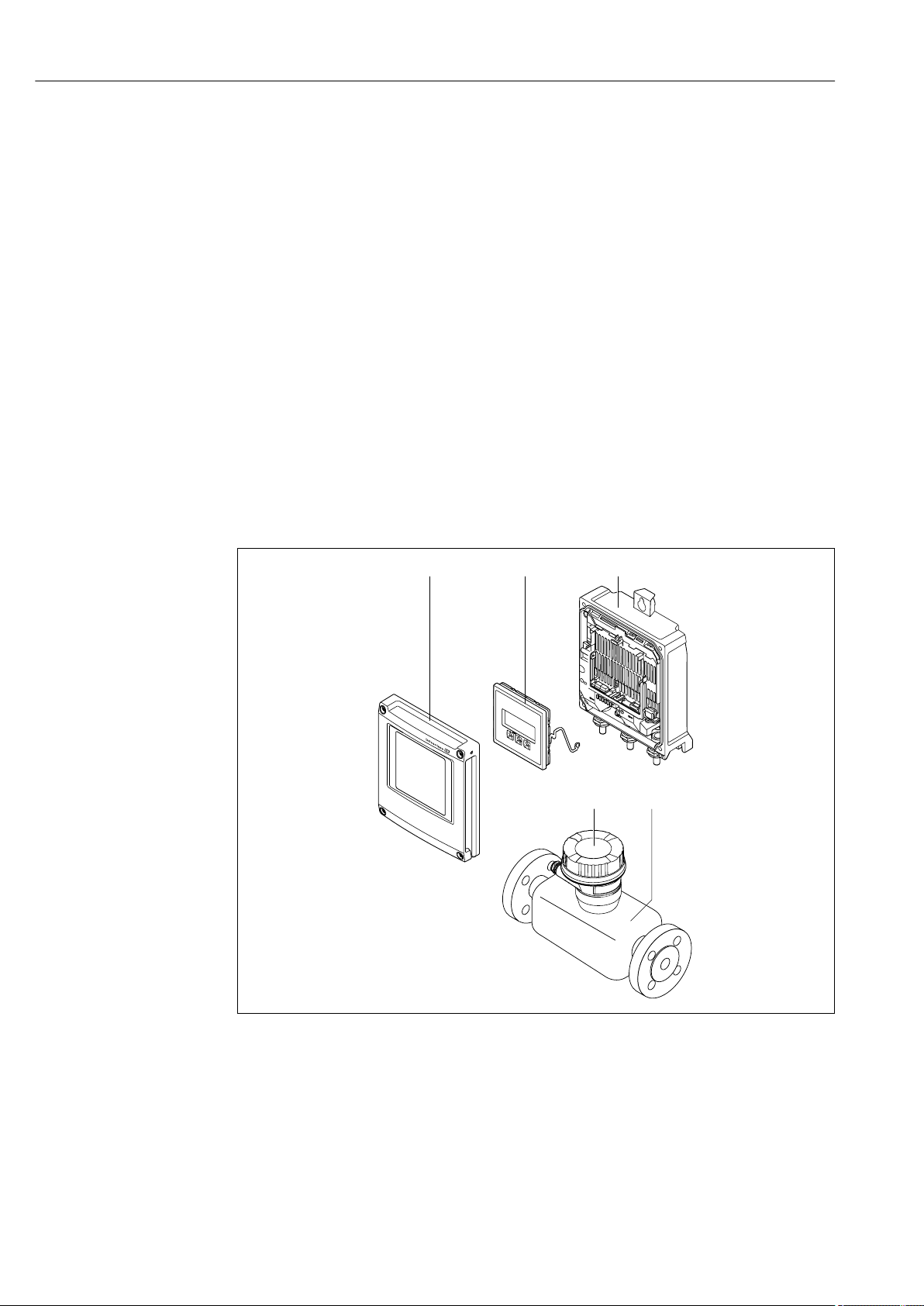
The measuring system consists of a transmitter and a sensor. The transmitter and sensor
are mounted in physically separate locations. They are interconnected by one connecting
cable(s).
3.1 Product design
Two versions of the transmitter are available.
3.1.1 Proline 500 – digital
Signal transmission: digital
Order code for "Integrated ISEM electronics", option A "Sensor"
For use in applications not required to meet special requirements due to ambient or
operating conditions.
As the electronics are located in the sensor, the device is ideal:
For simple transmitter replacement.
• A standard cable can be used as the connecting cable.
• Not sensitive to external EMC interference.
1 Important components of a measuring device
1 Electronics compartment cover
2 Display module
3 Transmitter housing
4 Sensor connection housing with integrated ISEM electronics: connecting cable connection
5 Sensor
A0029593
14 Endress+Hauser
Page 15
Proline Promass F 500 Modbus RS485 Product description
N
i
c
h
t
u
n
t
e
r
c
i
r
c
u
i
t
s
a
r
e
a
l
i
v
e
4
7
Nicht unter
Spannung öffnen
Do not open when
energized
Ne pas ouvrir
sous tension
Power
I/O
N
i
c
h
t
u
n
t
e
r
a
r
e
ö
f
f
n
e
n
D
i
s
p
l
a
y
+
E
ESC
–
1
2
3
5
6
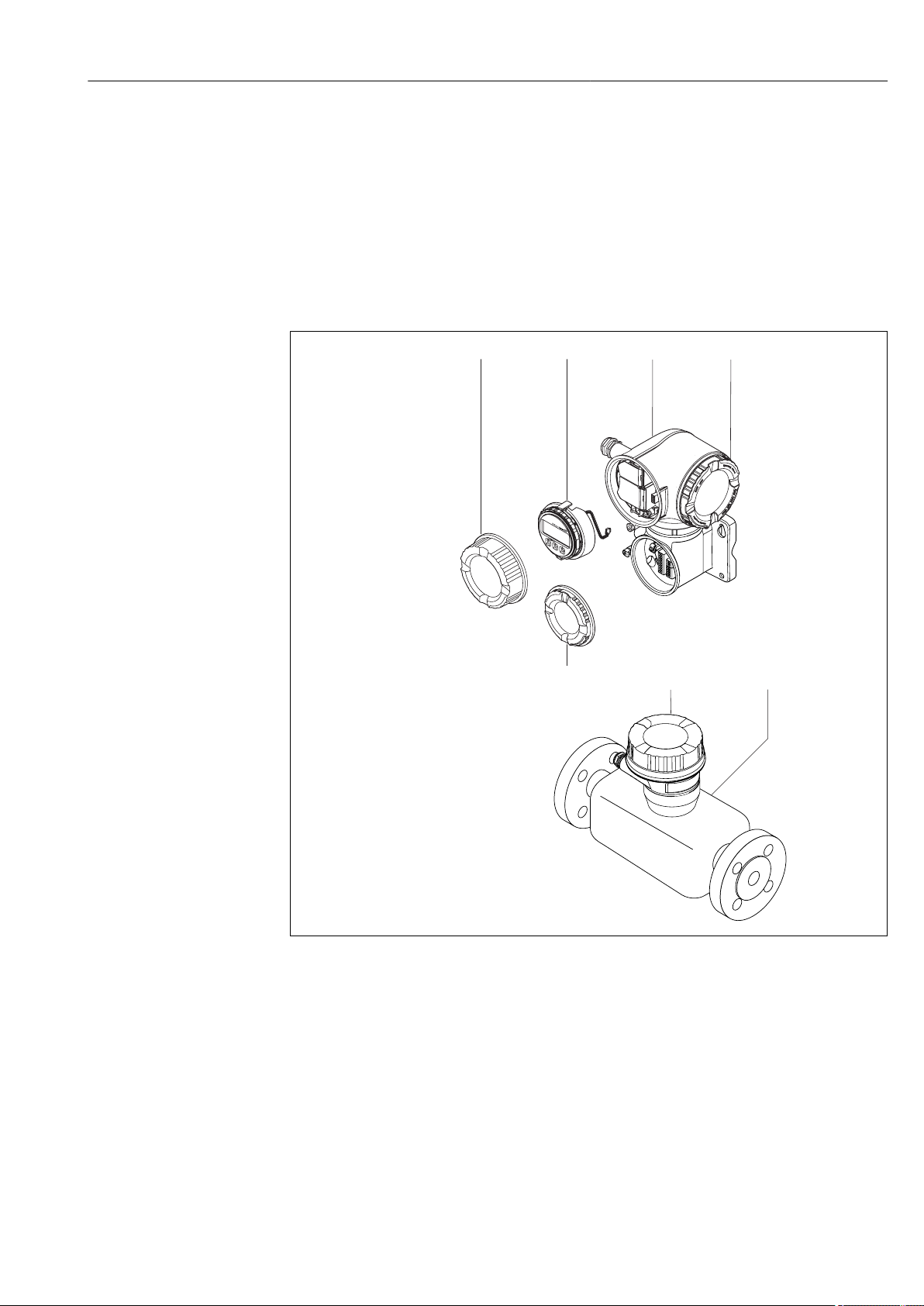
3.1.2 Proline 500
Signal transmission: analog
Order code for "Integrated ISEM electronics", option B "Transmitter"
For use in applications required to meet special requirements due to ambient or operating
conditions.
As the electronics are located in the transmitter, the device is ideal in the event of:
• Strong vibrations at the sensor.
• Sensor operation in underground installations.
• Permanent sensor immersion in water.
A0029589
2 Important components of a measuring device
1 Connection compartment cover
2 Display module
3 Transmitter housing with integrated ISEM electronics
4 Electronics compartment cover
5 Sensor
6 Sensor connection housing: connecting cable connection
7 Connection compartment cover: connecting cable connection
Endress+Hauser 15
Page 16
Incoming acceptance and product identification Proline Promass F 500 Modbus RS485
1
2
1
2
Order code:
Ser. no.:
Ext. ord. cd.:
i
i
Date:
4 Incoming acceptance and product
identification
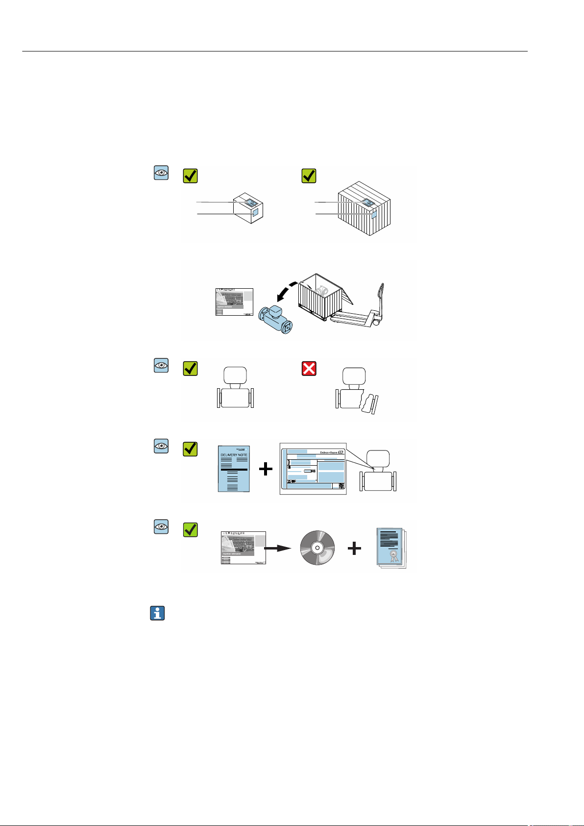
4.1 Incoming acceptance
Are the order codes on the
A0028673
A0029314
delivery note (1) and the
product sticker (2) identical?
A0029315
Are the goods undamaged?
A0028673
A0029316
Do the nameplate data
A0028673
match the ordering
information on the delivery
note?
A0029317
Is the CD-ROM with the
A0028673
Technical Documentation
(depends on device version)
and documents present?
A0029318
• If one of the conditions is not satisfied, contact your Endress+Hauser Sales Center.
• Depending on the device version, the CD-ROM might not be part of the delivery!
The Technical Documentation is available via the Internet or via the Endress+Hauser
Operations App, see the "Product identification" section → 17.
16 Endress+Hauser
Page 17
Proline Promass F 500 Modbus RS485 Incoming acceptance and product identification
Order code:
Ser. no.:
Ext. ord. cd.:
i
i
Date:
1
4
5
6
7
891012
2
13
11
3
4.2 Product identification
The following options are available for identification of the measuring device:
• Nameplate specifications
• Order code with breakdown of the device features on the delivery note
• Enter serial numbers from nameplates in W@M Device Viewer
(www.endress.com/deviceviewer): All information about the measuring device is
displayed.
• Enter the serial number from the nameplates into the Endress+Hauser Operations App
or scan the 2-D matrix code (QR code) on the nameplate with the Endress+Hauser
Operations App: all the information for the measuring device is displayed.
For an overview of the scope of the associated Technical Documentation, refer to the
following:
• The chapters "Additional standard documentation on the device" → 8 and
"Supplementary device-dependent documentation" → 8
• The W@M Device Viewer: Enter the serial number from the nameplate
(www.endress.com/deviceviewer)
• The Endress+Hauser Operations App: Enter the serial number from the nameplate or
scan the 2-D matrix code (QR code) on the nameplate.
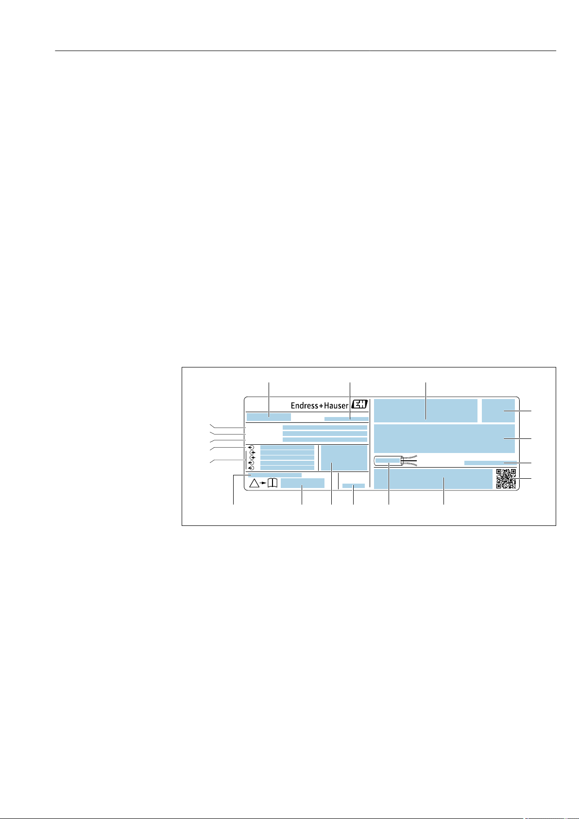
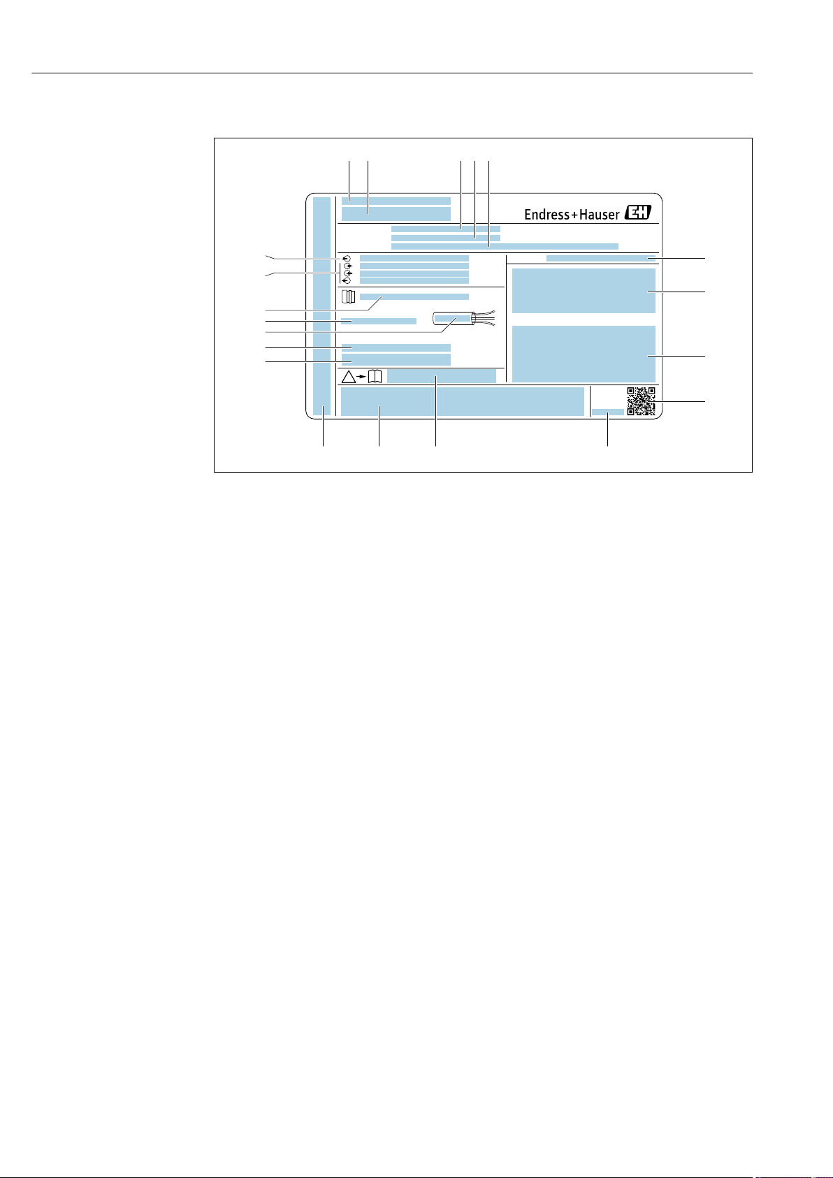
4.2.1 Transmitter nameplate
Proline 500 – digital
A0029194
3 Example of a transmitter nameplate
1 Name of the transmitter
2 Manufacturing location
3 Space for approvals: use in hazardous areas
4 Degree of protection
5 Electrical connection data: available inputs and outputs
6 Permitted ambient temperature (Ta)
7 2-D matrix code
8 Space for approvals and certificates: e.g. CE mark, C-Tick
9 Permitted temperature range for cable
10 Manufacturing date: year-month
11 Firmware version (FW) and device revision (Dev.Rev.) from the factory
12 Document number of safety-related supplementary documentation
13 Space for additional information in the case of special products
14 Available inputs and outputs, supply voltage
15 Electrical connection data: supply voltage
16 Extended order code (Ext. ord. cd.)
17 Serial number (ser. no.)
18 Order code
Endress+Hauser 17
Page 18
Incoming acceptance and product identification Proline Promass F 500 Modbus RS485
Order code:
Ser. no.:
Ext. ord. cd.:
i
i
Date:
1 2 3 4 5
6
7
8
9
13 12 1011
Proline 500
4 Example of a transmitter nameplate
1 Manufacturing location
2 Name of the transmitter
3 Order code
4 Serial number (ser. no.)
5 Extended order code (Ext. ord. cd.)
6 Degree of protection
7 Space for approvals: use in hazardous areas
8 Electrical connection data: available inputs and outputs
9 2-D matrix code
10 Manufacturing date: year-month
11 Document number of safety-related supplementary documentation
12 Space for approvals and certificates: e.g. CE mark, C-Tick
13 Space for degree of protection of connection and electronics compartment when used in hazardous areas
14 Firmware version (FW) and device revision (Dev.Rev.) from the factory
15 Space for additional information in the case of special products
16 Permitted temperature range for cable
17 Permitted ambient temperature (Ta)
18 Information on cable gland
19 Available inputs and outputs, supply voltage
20 Electrical connection data: supply voltage
A0029192
18 Endress+Hauser
Page 19
Proline Promass F 500 Modbus RS485 Incoming acceptance and product identification
Order code:
Ser. no.:
Ext. ord. cd.:
i
i
Date:
1
3
4
5
6
7
8
9
2
10
1112
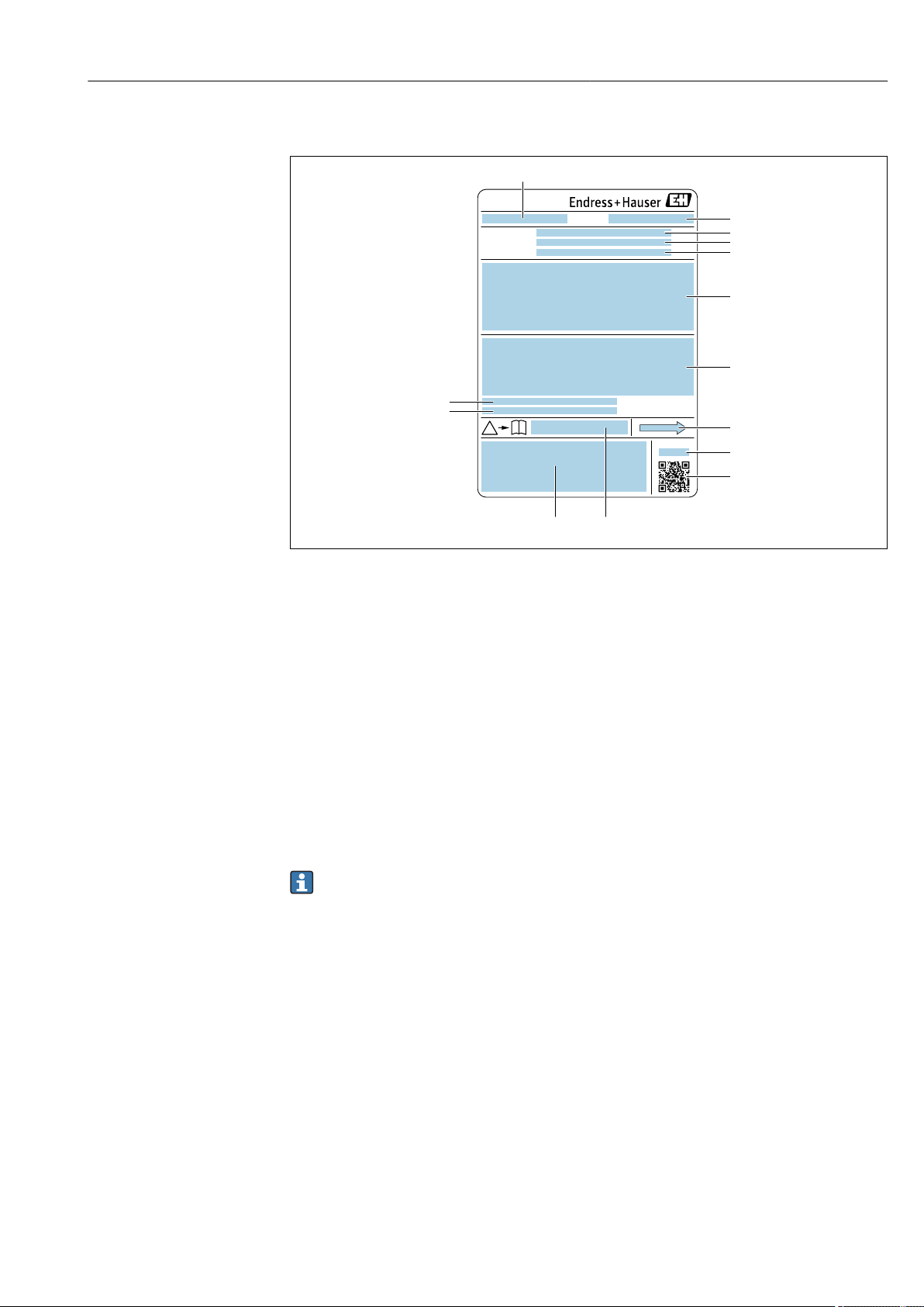
4.2.2 Sensor nameplate
A0029199
5 Example of a sensor nameplate
1 Name of the sensor
2 Manufacturing location
3 Order code
4 Serial number (ser. no.)
5 Extended order code (Ext. ord. cd.)
6 Nominal diameter of the sensor; flange nominal diameter/nominal pressure; sensor test pressure; medium
temperature range; material of measuring tube and manifold; sensor-specific information: e.g. pressure range
of secondary containment, wide-range density specification (special density calibration)
7 Approval information for explosion protection, Pressure Equipment Directive and degree of protection
8 Flow direction
9 Manufacturing date: year-month
10 2-D matrix code
11 Document number of safety-related supplementary documentation
12 CE mark, C-Tick
13 Surface roughness
14 Permitted ambient temperature (Ta)
Order code
The measuring device is reordered using the order code.
Extended order code
• The device type (product root) and basic specifications (mandatory features) are
always listed.
• Of the optional specifications (optional features), only the safety and approvalrelated specifications are listed (e.g. LA). If other optional specifications are also
ordered, these are indicated collectively using the # placeholder symbol (e.g. #LA#).
• If the ordered optional specifications do not include any safety and approval-related
specifications, they are indicated by the + placeholder symbol (e.g. XXXXXX-ABCDE
+).
Endress+Hauser 19
Page 20
Incoming acceptance and product identification Proline Promass F 500 Modbus RS485
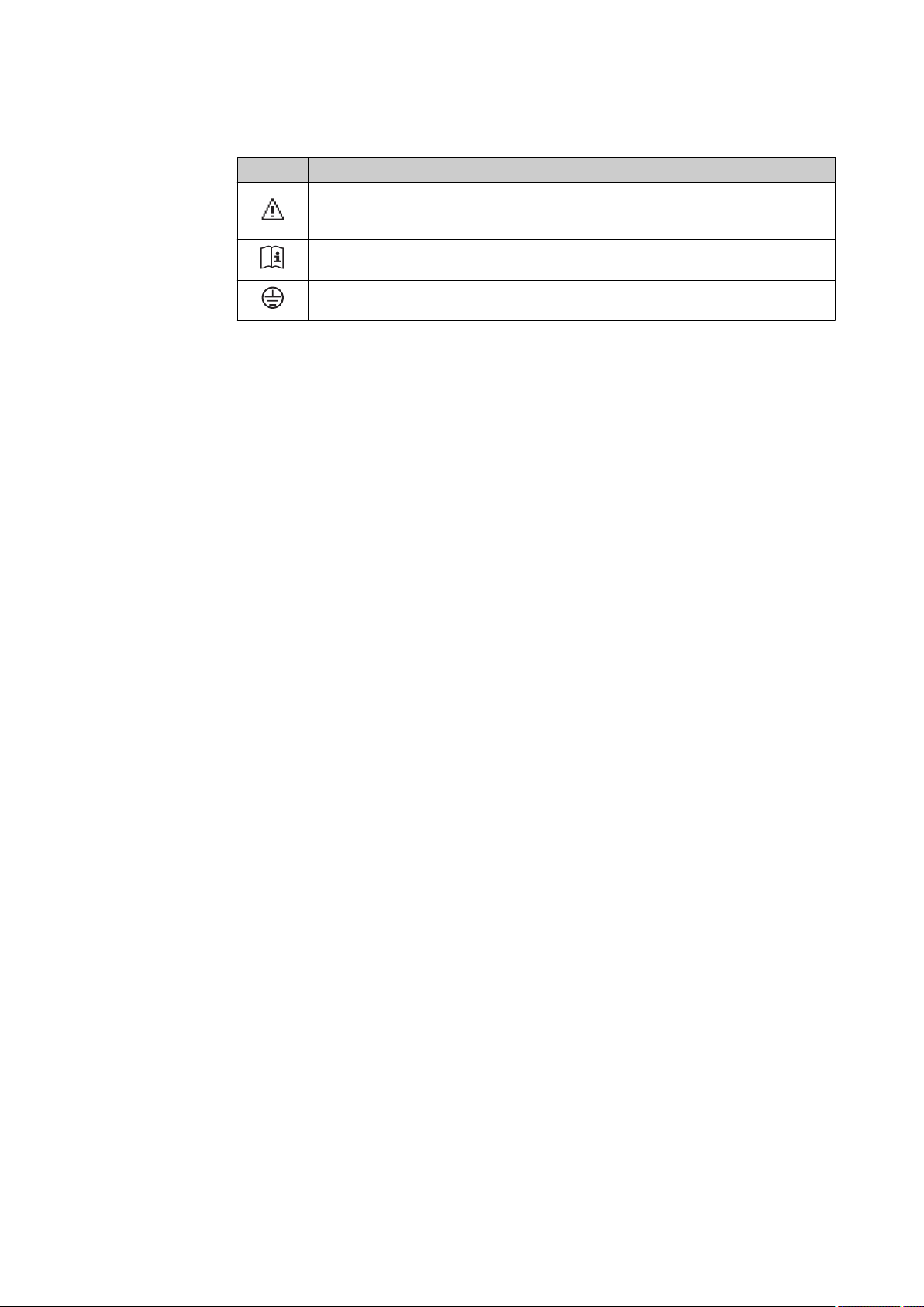
4.2.3 Symbols on measuring device
Symbol Meaning
WARNING!
This symbol alerts you to a dangerous situation. Failure to avoid this situation can result in serious
or fatal injury.
Reference to documentation
Refers to the corresponding device documentation.
Protective ground connection
A terminal which must be connected to ground prior to establishing any other connections.
20 Endress+Hauser
Page 21
Proline Promass F 500 Modbus RS485 Storage and transport
5 Storage and transport
5.1 Storage conditions
Observe the following notes for storage:
• Store in the original packaging to ensure protection from shock.
• Do not remove protective covers or protective caps installed on process connections.
They prevent mechanical damage to the sealing surfaces and contamination in the
measuring tube.
• Protect from direct sunlight to avoid unacceptably high surface temperatures.
• Store in a dry and dust-free place.
• Do not store outdoors.
Storage temperature: –50 to +80 °C (–58 to +176 °F),
5.2 Transporting the product
Transport the measuring device to the measuring point in the original packaging.
A0029252
Do not remove protective covers or caps installed on process connections. They
prevent mechanical damage to the sealing surfaces and contamination in the
measuring tube.
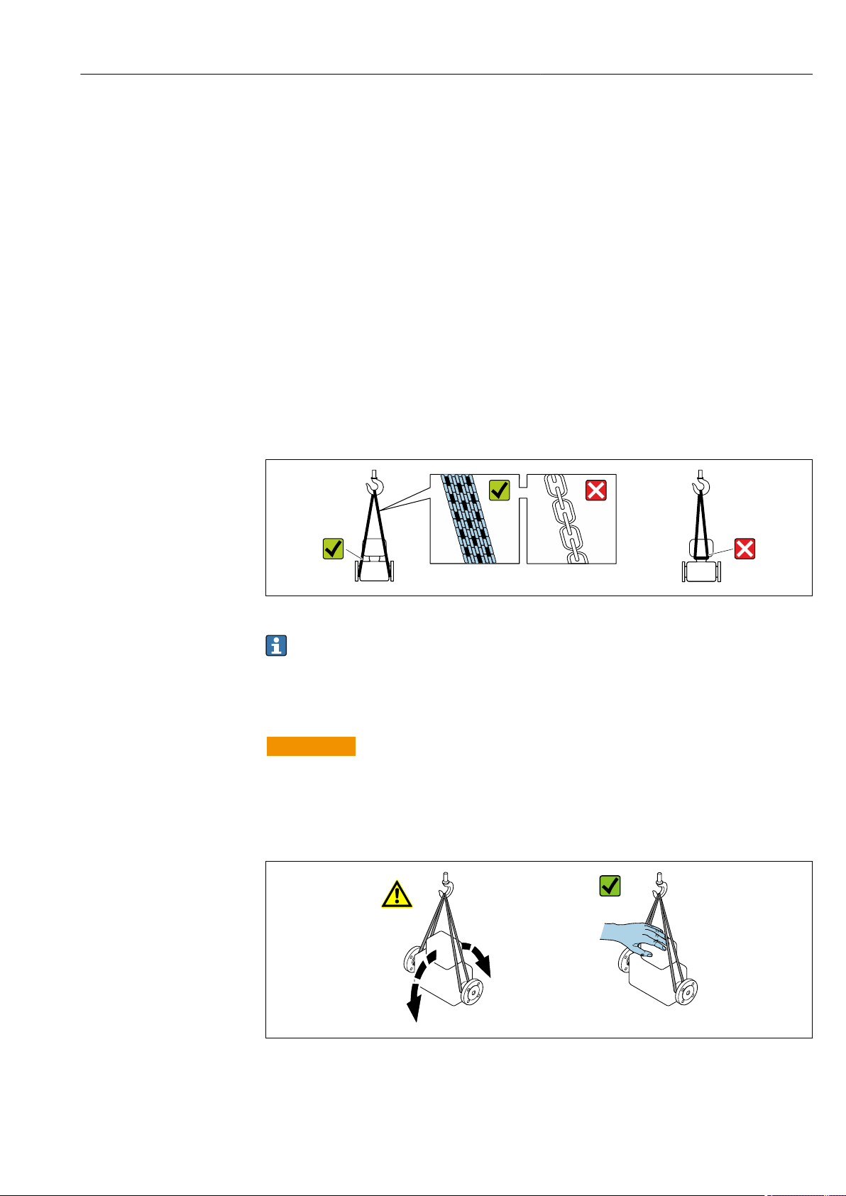
5.2.1 Measuring devices without lifting lugs
WARNING
L
Center of gravity of the measuring device is higher than the suspension points of the
webbing slings.
Risk of injury if the measuring device slips.
Secure the measuring device against slipping or turning.
‣
Observe the weight specified on the packaging (stick-on label).
‣
A0029214
Endress+Hauser 21
Page 22
Installation Proline Promass F 500 Modbus RS485
5.2.2 Measuring devices with lifting lugs
CAUTION
L
Special transportation instructions for devices with lifting lugs
Only use the lifting lugs fitted on the device or flanges to transport the device.
‣
The device must always be secured at two lifting lugs at least.
‣
5.2.3 Transporting with a fork lift
If transporting in wood crates, the floor structure enables the crates to be lifted lengthwise
or at both sides using a forklift.
5.3 Packaging disposal
All packaging materials are environmentally friendly and 100% recyclable:
• Measuring device secondary packaging: polymer stretch film that conforms to EC
Directive 2002/95/EC (RoHS).
• Packaging:
– Wood crate, treated in accordance with ISPM 15 standard, which is confirmed by the
affixed IPPC logo.
or
– Carton in accordance with European Packaging Directive 94/62EC; recyclability is
confirmed by the affixed RESY symbol.
• Seaworthy packaging (optional): Wood crate, treated in accordance with ISPM 15
standard, which is confirmed by the affixed IPPC logo.
• Carrying and mounting hardware:
– Disposable plastic pallet
– Plastic straps
– Plastic adhesive strips
• Dunnage: Paper cushion
6 Installation
6.1 Installation conditions
No special measures such as supports are necessary. External forces are absorbed by the
construction of the device.
6.1.1 Mounting position
Mounting location
A0028772
22 Endress+Hauser
Page 23
Proline Promass F 500 Modbus RS485 Installation
1
2
3
4
5
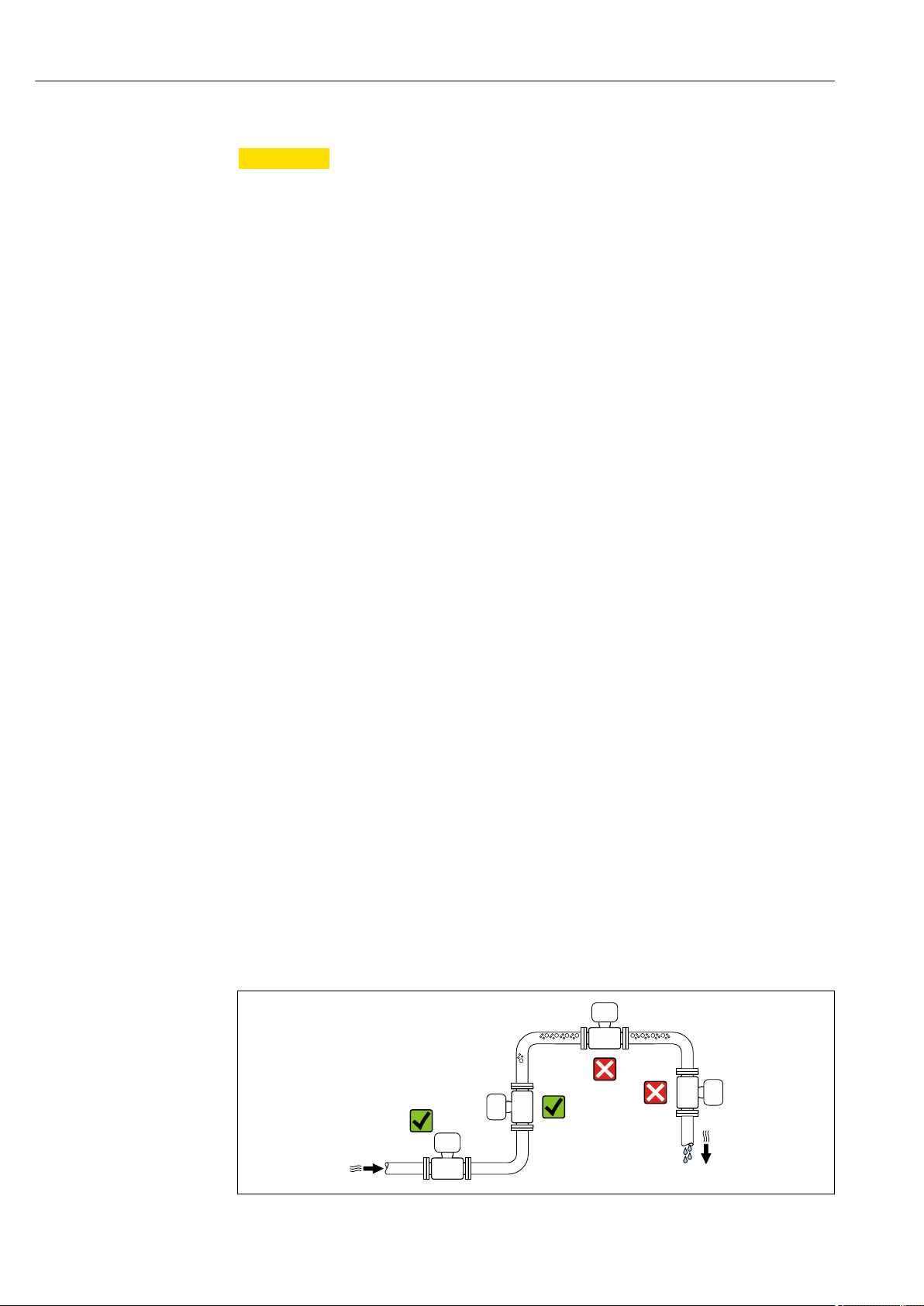
To prevent measuring errors arising from accumulation of gas bubbles in the measuring
tube, avoid the following mounting locations in the pipe:
• Highest point of a pipeline.
• Directly upstream of a free pipe outlet in a down pipe.
Installation in down pipes
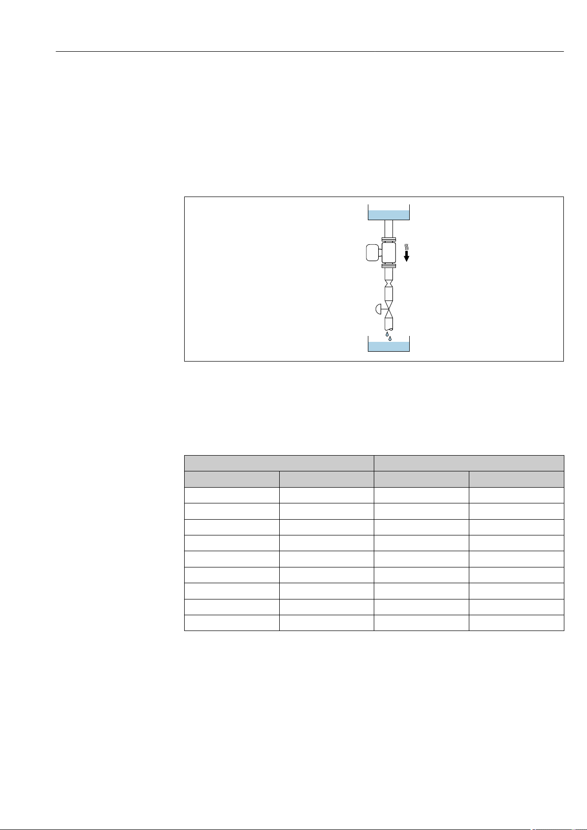
However, the following installation suggestion allows for installation in an open vertical
pipeline. Pipe restrictions or the use of an orifice with a smaller cross-section than the
nominal diameter prevent the sensor running empty while measurement is in progress.
6 Installation in a down pipe (e.g. for batching applications)
1 Supply tank
2 Sensor
3 Orifice plate, pipe restriction
4 Valve
5 Batching tank
DN Ø orifice plate, pipe restriction
[mm] [in] [mm] [in]
8 ³⁄₈ 6 0.24
15 ½ 10 0.40
25 1 14 0.55
40 1½ 22 0.87
50 2 28 1.10
80 3 50 1.97
100 4 65 2.60
150 6 90 3.54
250 10 150 5.91
A0028773
Orientation
The direction of the arrow on the sensor nameplate helps you to install the sensor
according to the flow direction (direction of medium flow through the piping).
Endress+Hauser 23
Page 24
Installation Proline Promass F 500 Modbus RS485
1 2
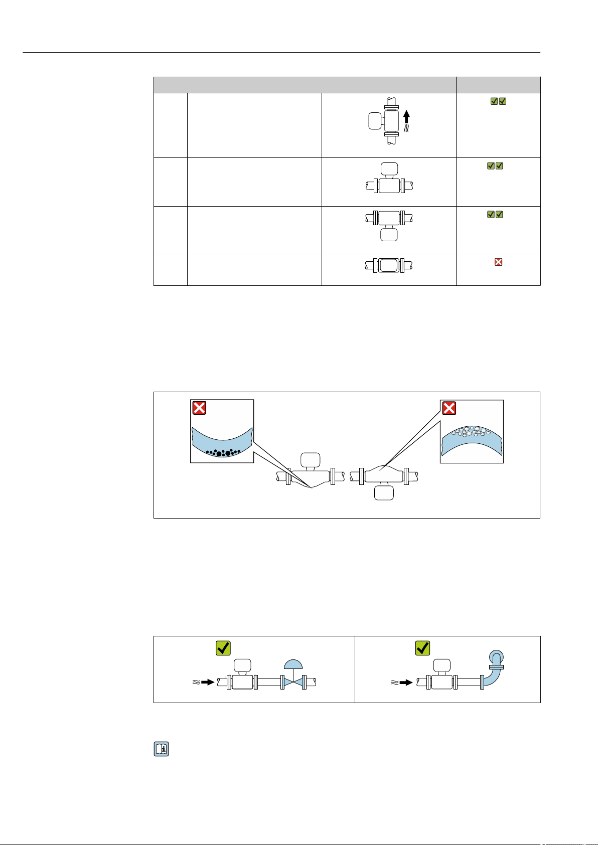
Orientation Recommendation
A Vertical orientation
A0015591
B Horizontal orientation, transmitter at
top
A0015589
C Horizontal orientation, transmitter at
bottom
A0015590
D Horizontal orientation, transmitter at
side
A0015592
1) Applications with low process temperatures may decrease the ambient temperature. To maintain the
minimum ambient temperature for the transmitter, this orientation is recommended.
2) Applications with high process temperatures may increase the ambient temperature. To maintain the
maximum ambient temperature for the transmitter, this orientation is recommended.
1)
Exceptions:
→ 7, 24
2)
Exceptions:
→ 7, 24
If a sensor is installed horizontally with a curved measuring tube, match the position of the
sensor to the fluid properties.
A0028774
7 Orientation of sensor with curved measuring tube
1 Avoid this orientation for fluids with entrained solids: Risk of solids accumulating.
2 Avoid this orientation for outgassing fluids: Risk of gas accumulating.
Inlet and outlet runs
No special precautions need to be taken for fittings which create turbulence, such as
valves, elbows or T-pieces, as long as no cavitation occurs → 25.
A0029322 A0029323
Installation dimensions
For the dimensions and installation lengths of the device, see the "Technical
Information" document, "Mechanical construction" section
24 Endress+Hauser
Page 25
Proline Promass F 500 Modbus RS485 Installation
6.1.2 Requirements from environment and process
Ambient temperature range
Measuring device Non-Ex –40 to +60 °C (–40 to +140 °F)
Ex ec, NI version –40 to +60 °C (–40 to +140 °F)
Ex ia, IS version • –40 to +60 °C (–40 to +140 °F)
• Order code for "Test, certificate", option JP
–50 to +60 °C (–58 to +140 °F)
• Order code for "Test, certificate", option JQ
–60 to +60 °C (–76 to +140 °F) (sensor)
–50 to +60 °C (–58 to +140 °F) (transmitter)
Readability of the local display –20 to +60 °C (–4 to +140 °F)
The readability of the display may be impaired at temperatures outside
the temperature range.
If operating outdoors:
‣
Avoid direct sunlight, particularly in warm climatic regions.
You can order a weather protection cover from Endress+Hauser : → 178
System pressure
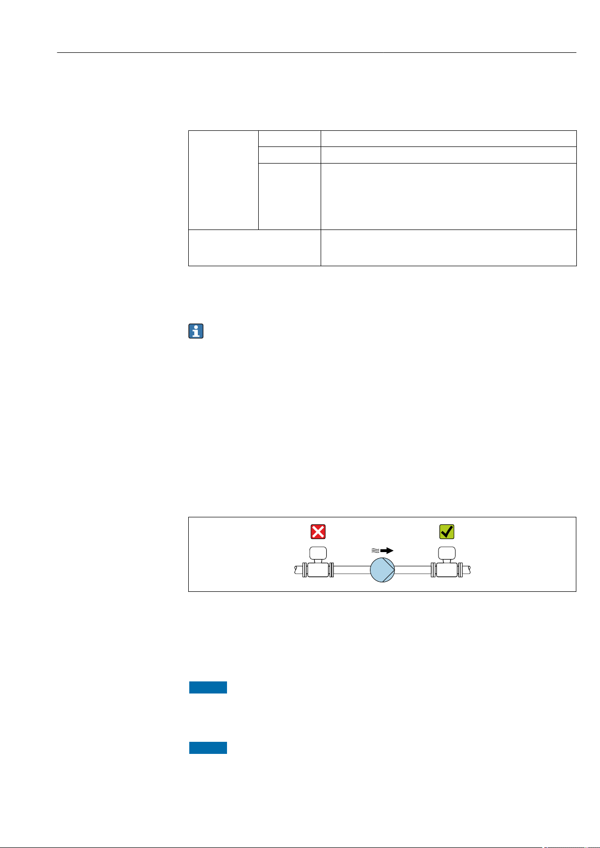
It is important that cavitation does not occur, or that gases entrained in the liquids do not
outgas.
Cavitation is caused if the pressure drops below the vapor pressure:
• In liquids that have a low boiling point (e.g. hydrocarbons, solvents, liquefied gases)
• In suction lines
Ensure the system pressure is sufficiently high to prevent cavitation and outgassing.
‣
For this reason, the following mounting locations are recommended:
• At the lowest point in a vertical pipe
• Downstream from pumps (no danger of vacuum)
A0028777
Thermal insulation
In the case of some fluids, it is important that the heat radiated from the sensor to the
transmitter is kept to a minimum. A wide range of materials can be used for the required
insulation.
NOTICE
Electronics overheating on account of thermal insulation!
Observe maximum permitted insulation height of the transmitter neck so that the
‣
transmitter head is completely free.
NOTICE
Danger of overheating with insulation
Ensure that the temperature at the lower end of the sensor housing does not exceed
‣
80 °C (176 °F)
Endress+Hauser 25
Page 26

Installation Proline Promass F 500 Modbus RS485
t
a
0
10
30
20
40
[ ]mm[ ]in
80 90 100 110
[°C]
[°F]
200 250 290
0.5
1.0
1.5
0
t
40(104)
t
60(140)
t
120 130 140
T
m
150
NOTICE
The insulation can also be thicker than the maximum recommended insulation
thickness.
Prerequisite:
Ensure that convection takes place on a sufficiently large scale at the transmitter neck.
‣
Ensure that a sufficiently large area of the housing support remains exposed. The
‣
uncovered part serves as a radiator and protects the electronics from overheating and
excessive cooling.
A0028853
a Minimum distance to insulation
t maximum Insulation thickness
The minimum distance a between the sensor connection housing and the insulation is
10 mm (0.39 in). This is to ensure that the sensor connection housing remains completely
exposed.
Maximum recommended insulation thickness
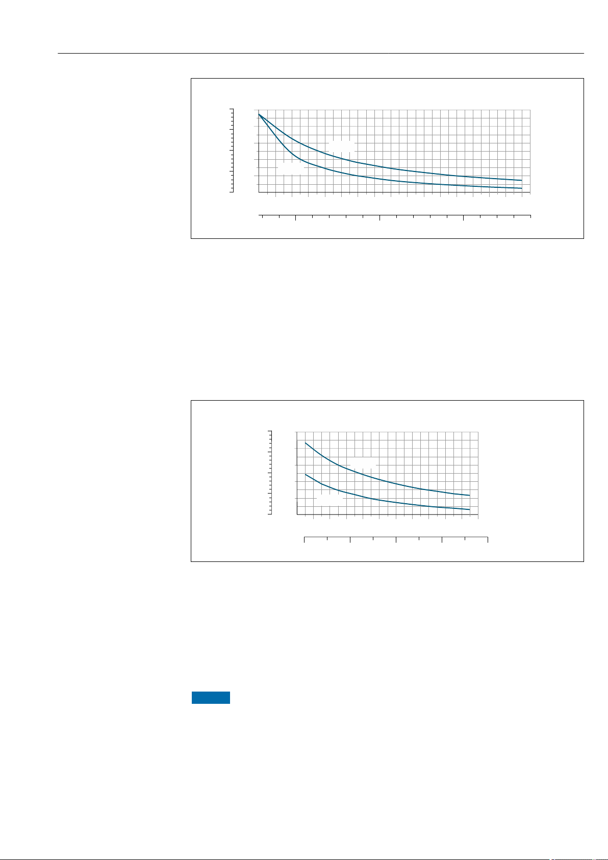
A0028904
8 Maximum recommended insulation thickness depending on the temperature of the medium and the
ambient temperature
t Insulation thickness
T
t40
t60
m
(104)
(140)
Medium temperature
Maximum recommended insulation thickness at an ambient temperature of Ta = 40 °C (104 °F)
Maximum recommended insulation thickness at an ambient temperature of Ta = 60 °C (140 °F)
Maximum recommended insulation thickness for the extended temperature range or
insulation
For the extended temperature range, version with long extension neck, order code for
"Measuring tube material", option SD, SE, SF, TH or extension neck for insulation, order
26 Endress+Hauser
code for "Sensor option", option CG:
Page 27
Proline Promass F 500 Modbus RS485 Installation
0
20
60
40
80
1
2
3
0
t
100
4
[ ]mm
t
40(104)
t
60(140)
80 100 120 140
200 300 400
160 180 200
[°F]
T
m
[°C]
220
240
0
10
30
20
40
0.5
1.0
1.5
0
t
50
2.0
[mm]
t
40(104)
t
60(140)
200
240
300
500 700
280
[°F]
T
m
[°C]
320
160
360
600400
A0028906
t Insulation thickness
T
t40
t60
m
(104)
(140)
Medium temperature
Maximum recommended insulation thickness at an ambient temperature of Ta = 40 °C (104 °F)
Maximum recommended insulation thickness at an ambient temperature of Ta = 60 °C (140 °F)
Maximum recommended insulation thickness for the high-temperature range
For the extended temperature range, version with long extension neck, order code for
"Measuring tube material", option TT, TU:
t Insulation thickness
T
t40
t60
m
(104)
(140)
Medium temperature
Maximum recommended insulation thickness at an ambient temperature of Ta = 40 °C (104 °F)
Maximum recommended insulation thickness at an ambient temperature of Ta = 60 °C (140 °F)
A0029903
Endress+Hauser 27
Heating
NOTICE
Electronics can overheat due to elevated ambient temperature!
‣
‣
Observe maximum permitted ambient temperature for the transmitter .
Depending on the fluid temperature, take the device orientation requirements into
account .
Page 28

Installation Proline Promass F 500 Modbus RS485
NOTICE
Danger of overheating when heating
Ensure that the temperature at the lower end of the transmitter housing does not
‣
exceed 80 °C (176 °F).
Ensure that convection takes place on a sufficiently large scale at the transmitter neck.
‣
Ensure that a sufficiently large area of the housing support remains exposed. The
‣
uncovered part serves as a radiator and protects the electronics from overheating and
excessive cooling.
Heating options
If a fluid requires that no heat loss should occur at the sensor, users can avail of the
following heating options:
• Electrical heating, e.g. with electric band heaters
• Via pipes carrying hot water or steam
• Via heating jackets
Using an electrical trace heating system
If heating is regulated via phase angle control or pulse packages, magnetic fields can affect
the measured values (= for values that are greater than the values permitted by the EN
standard (sine 30 A/m)).
For this reason, the sensor must be magnetically shielded: the housing can be shielded
with tin plates or electric sheets without a privileged direction (e.g. V330-35A).
The sheet must have the following properties:
• Relative magnetic permeability µr ≥ 300
• Plate thickness d ≥ 0.35 mm (d ≥ 0.014 in)
Vibrations
The high oscillation frequency of the measuring tubes ensures that the correct operation of
the measuring system is not influenced by plant vibrations.
6.1.3 Special mounting instructions
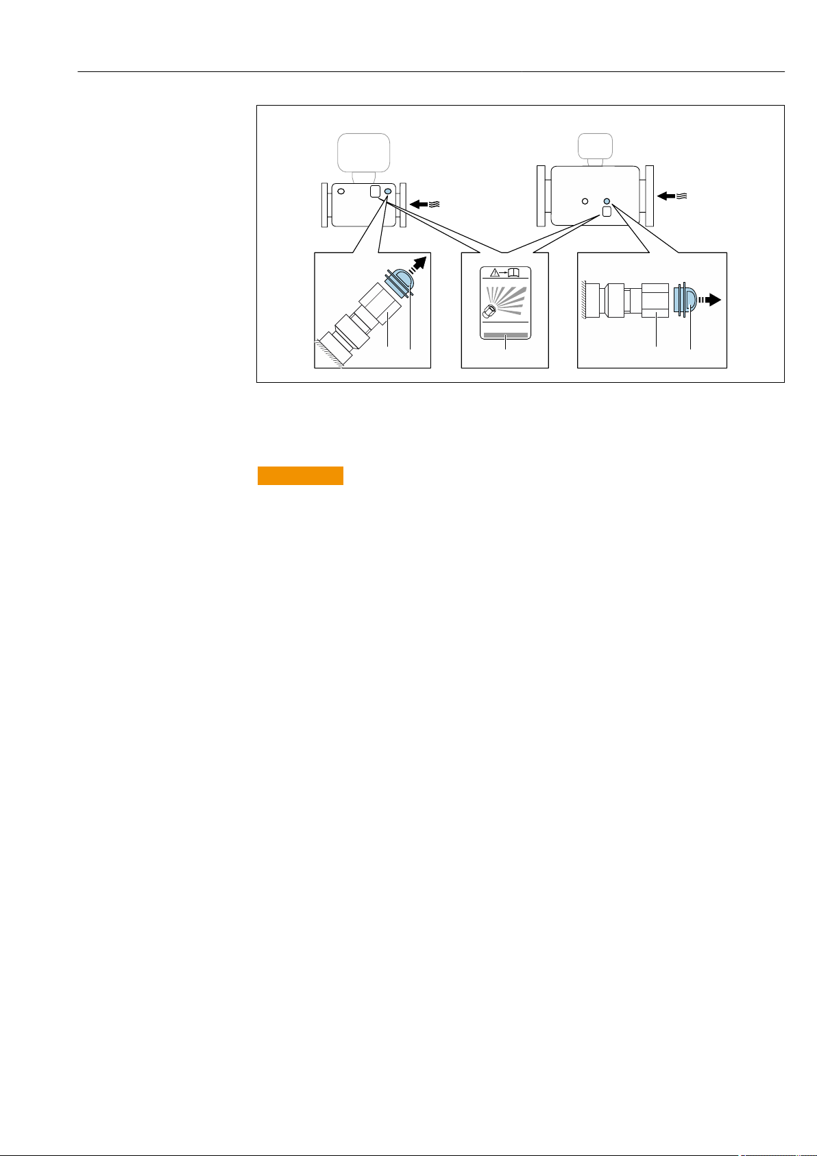
Rupture disk
Make sure that the function and operation of the rupture disk is not impeded through the
installation of the device. The position of the rupture disk is indicated on a sticker beside it.
The transportation guard must be removed.
Information that is relevant to the process: → 197.
For information on the dimensions: see the "Mechanical construction" section of the
"Technical Information" document
The existing connecting nozzles are not intended for the purpose of rinsing or pressure
monitoring, but instead serve as the mounting location for the rupture disk.
In the event of a failure of the rupture disk, a discharge device can be screwed onto the
internal thread of the rupture disk in order to drain off any escaping medium.
28 Endress+Hauser
Page 29
Proline Promass F 500 Modbus RS485 Installation
RUPTURE DISK
i
2
3
1
2
3
A0028903
1 Rupture disk label
2 Rupture disk with 1/2" NPT internal thread with 1" width across flat
3 Transport protection
WARNING
L
Limited functional reliability of the rupture disk.
Danger to persons from escaping fluids!
Do not remove the rupture disk.
‣
When using a rupture disk, do not use a heating jacket.
‣
Make sure that the function and operation of the rupture disk is not impeded through
‣
the installation of the device.
Take precautions to prevent damage and danger to persons if the rupture disk is
‣
actuated.
Observe information on the rupture disk sticker.
‣
Zero point adjustment
All measuring devices are calibrated in accordance with state-of-the-art technology.
Calibration takes place under reference conditions → 190. Therefore, a zero point
adjustment in the field is generally not required.
Experience shows that zero point adjustment is advisable only in special cases:
• To achieve maximum measuring accuracy even with low flow rates
• Under extreme process or operating conditions (e.g. very high process temperatures or
very high-viscosity fluids).
Endress+Hauser 29
Page 30
Installation Proline Promass F 500 Modbus RS485
213 (8.4)
39 (1.5)
243 (9.6)
203 (8.0)
280 (11.0)
66 (2.6)
270 (10.5)
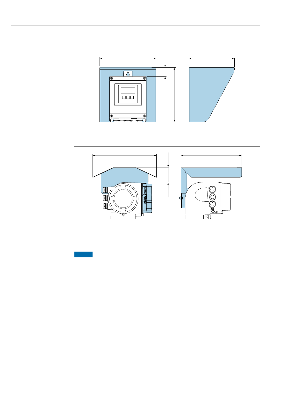
Protective cover
A0029552
9 Weather protection cover for Proline 500 – digital
10 Weather protection cover for Proline 500
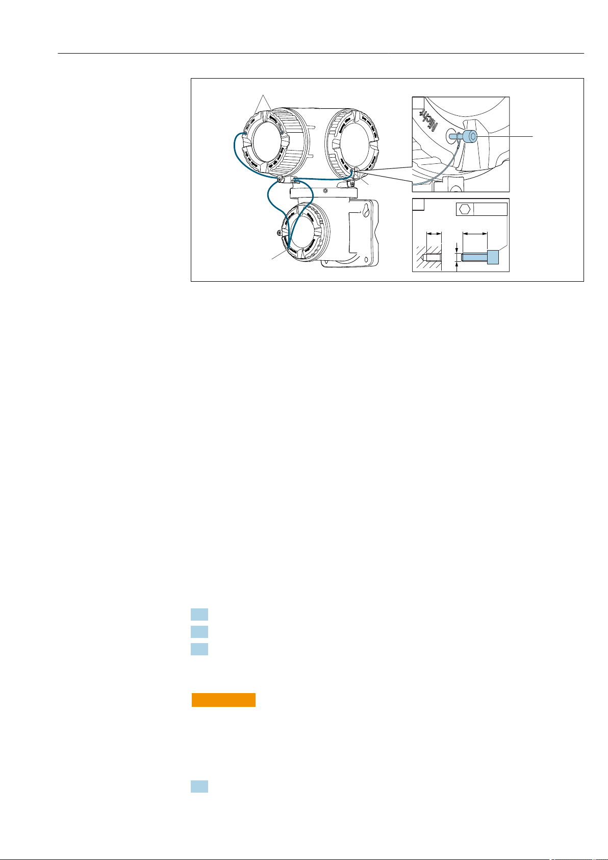
Cover locking: Proline 500
NOTICE
Order code for "Housing", option L "Cast, stainless": The covers of the transmitter
housing are provided with a borehole to lock the cover.
The cover can be locked using screws and a chain or cable provided by the customer.
It is recommended to use stainless steel cables or chains.
‣
If a protective coating is applied, it is recommended to use a heat shrink tube to protect
‣
the housing paint.
A0029553
30 Endress+Hauser
Page 31
Proline Promass F 500 Modbus RS485 Installation
1
1
2
2
1
1
5 (0.2) min. 15 (0.6)
SW 2.5
M3
A0029799
1 Cover borehole for the securing screw
2 Securing screw to lock the cover
6.2 Mounting the measuring device
6.2.1 Required tools
For transmitter
For mounting on a post:
• Proline 500 – digital transmitter
– Open-ended wrench AF 10
– Torx screwdriver TX 25
• Proline 500 transmitter
Open-ended wrench AF 13
For wall mounting:
Drill with drill bit ⌀ 6.0 mm
For sensor
For flanges and other process connections: Corresponding mounting tools
6.2.2 Preparing the measuring device
1. Remove all remaining transport packaging.
2. Remove any protective covers or protective caps present from the sensor.
3. Remove stick-on label on the electronics compartment cover.
6.2.3 Mounting the measuring device
WARNING
L
Danger due to improper process sealing!
Ensure that the inside diameters of the gaskets are greater than or equal to that of the
‣
process connections and piping.
Ensure that the gaskets are clean and undamaged.
‣
Install the gaskets correctly.
‣
1. Ensure that the direction of the arrow on the nameplate of the sensor matches the
flow direction of the fluid.
Endress+Hauser 31
Page 32
Installation Proline Promass F 500 Modbus RS485
ø 20…70
( 0.79…2.75)ø
~102 (~ 4.0)
4 x
SW 10
3 x
TX 25
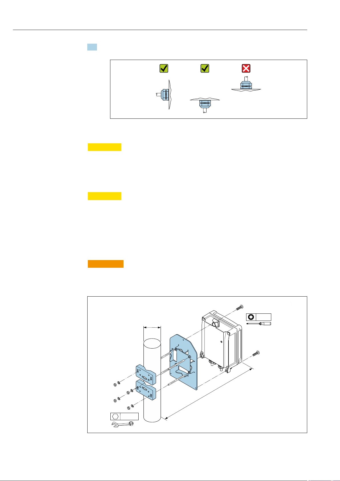
2. Install the measuring device or turn the transmitter housing so that the cable entries
do not point upwards.
A0029263
6.2.4 Mounting the transmitter housing: Proline 500 – digital
CAUTION
L
Ambient temperature too high!
Danger of electronics overheating and housing deformation.
Do not exceed the permitted maximum ambient temperature .
‣
If operating outdoors: Avoid direct sunlight and exposure to weathering, particularly in
‣
warm climatic regions.
CAUTION
L
Excessive force can damage the housing!
Avoid excessive mechanical stress.
‣
The transmitter can be mounted in the following ways:
• Post mounting
• Wall mounting
Post mounting
WARNING
L
Excessive tightening torque applied to the fixing screws!
Risk of damaging the plastic transmitter.
Tighten the fixing screws as per the tightening torque: 2 Nm (1.5 lbf ft).
‣
11 Engineering unit mm (in)
32 Endress+Hauser
A0029051
Page 33
Proline Promass F 500 Modbus RS485 Installation
149 (5.85)
211 (8.31)
=
5.8 (0.23)
17 (0.67) =
14 (0.55)
5.8 (0.23)
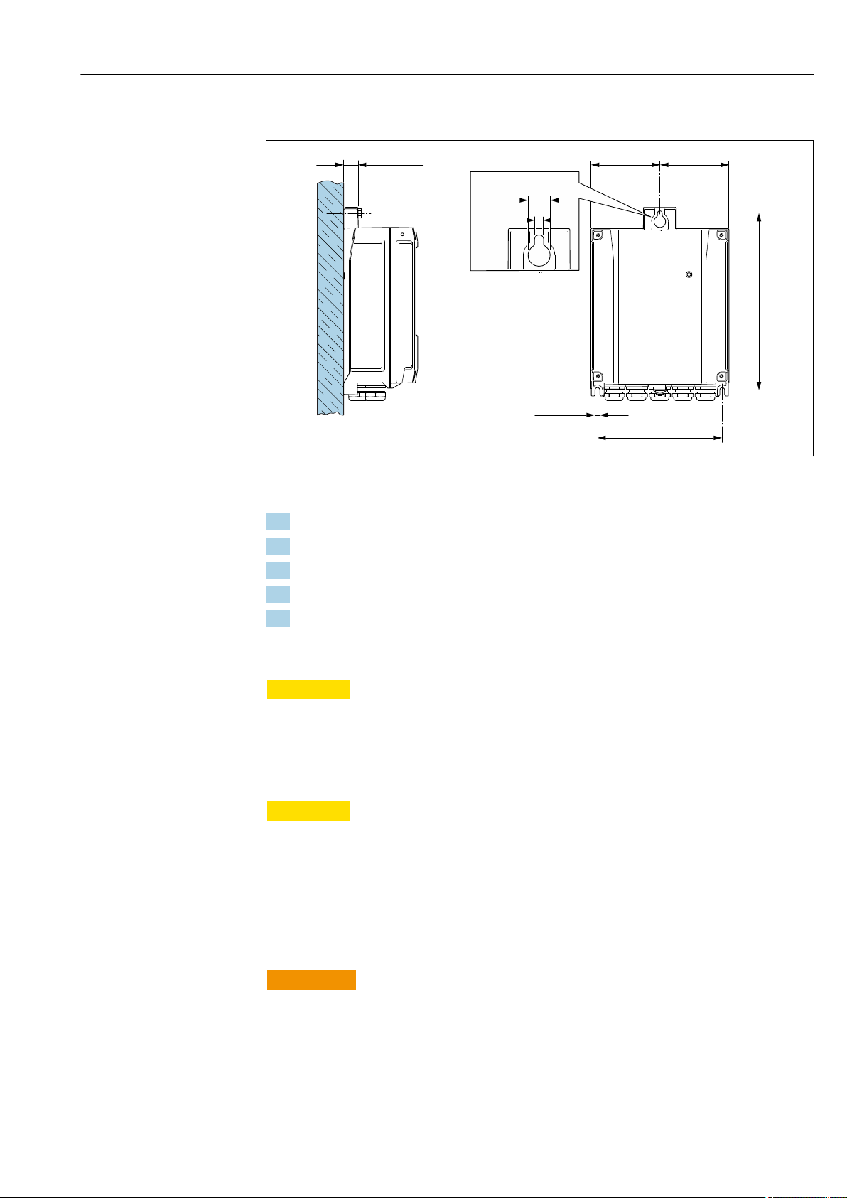
Wall mounting
A0029054
12 Engineering unit mm (in)
1. Drill the holes.
2. Insert wall plugs into the drilled holes.
3. Screw in the securing screws slightly at first.
4. Fit the transmitter housing over the securing screws and mount in place.
5. Tighten the securing screws.
6.2.5 Mounting the transmitter housing: Proline 500
CAUTION
L
Ambient temperature too high!
Danger of electronics overheating and housing deformation.
Do not exceed the permitted maximum ambient temperature .
‣
If operating outdoors: Avoid direct sunlight and exposure to weathering, particularly in
‣
warm climatic regions.
CAUTION
L
Excessive force can damage the housing!
Avoid excessive mechanical stress.
‣
The transmitter can be mounted in the following ways:
• Post mounting
• Wall mounting
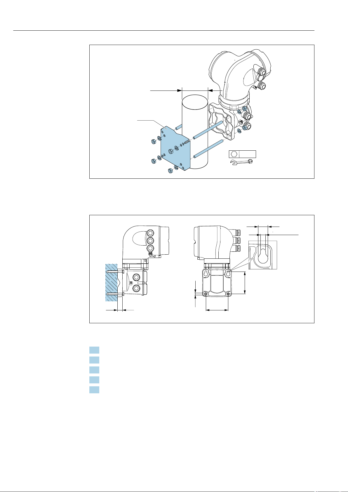
Post mounting
WARNING
L
Order code for "Transmitter housing", option L "Cast, stainless": cast transmitters are
very heavy.
They are unstable if they are not mounted on a secure, fixed post.
Only mount the transmitter on a secure, fixed post on a stable surface.
‣
Endress+Hauser 33
Page 34
Installation Proline Promass F 500 Modbus RS485
4 x
SW 13
! … (! 0.79 to 2.75)20 70
20 (0.79)
100 (3.94)
100 (3.94)
! 8.6 (0.39)
! 18 (0.71)
! 10 (0.39)
A0029057
13 Engineering unit mm (in)
Wall mounting
14 Engineering unit mm (in)
1. Drill the holes.
2. Insert wall plugs into the drilled holes.
3. Screw in the securing screws slightly at first.
4. Fit the transmitter housing over the securing screws and mount in place.
5. Tighten the securing screws.
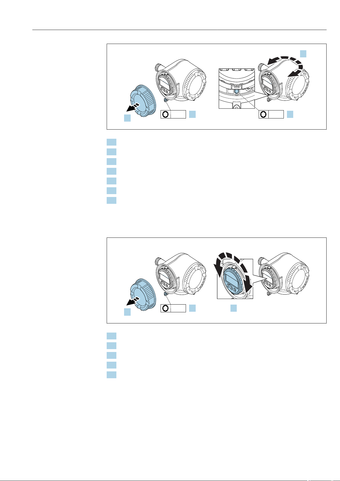
6.2.6 Turning the transmitter housing: Proline 500
A0029068
To provide easier access to the connection compartment or display module, the transmitter
housing can be turned.
34 Endress+Hauser
Page 35
Proline Promass F 500 Modbus RS485 Installation
N
i
c
h
t
u
n
t
e
r
a
r
e
ö
f
f
n
e
n
+
E
ESC
–
1.
2.
N
i
c
h
t
u
n
t
e
r
a
r
e
ö
f
f
n
e
n
+
E
ESC
–
3.
3 mm 4 mm
4.
N
i
c
h
t
u
n
t
e
r
a
r
e
ö
f
f
n
e
n
+
E
ESC
–
1.
2.
N
i
c
h
t
u
n
t
e
r
a
r
e
ö
f
f
n
e
n
+
E
ESC
–
3.
3 mm
+
E
ESC
–
A0029993
1. Loosen the securing clamp of the connection compartment cover.
2. Unscrew the connection compartment cover.
3. Release the fixing screw.
4. Turn the housing to the desired position.
5. Firmly tighten the securing screw.
6. Screw on the connection compartment cover
7. Fit the securing clamp of the connection compartment cover.
6.2.7 Turning the display module: Proline 500
The display module can be turned to optimize display readability and operability.
1. Loosen the securing clamp of the connection compartment cover.
2. Unscrew the connection compartment cover.
3. Turn the display module to the desired position: max. 8 × 45° in every direction.
4. Screw on the connection compartment cover.
5. Fit the securing clamp of the connection compartment cover.
A0030035
Endress+Hauser 35
Page 36
Installation Proline Promass F 500 Modbus RS485
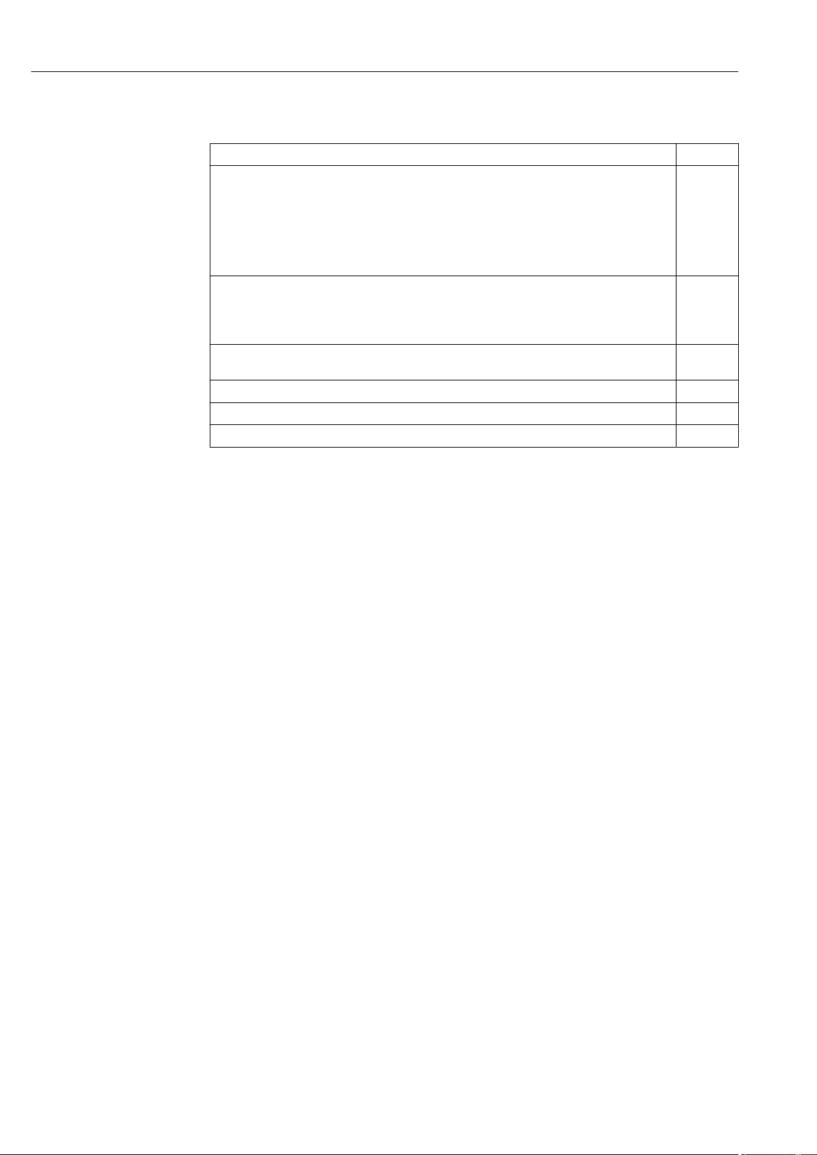
6.3 Post-installation check
Is the device undamaged (visual inspection)?
Does the measuring device conform to the measuring point specifications?
For example:
• Process temperature → 196
• Process pressure (refer to the chapter on "Pressure-temperature ratings" of the "Technical
Information" document)
• Ambient temperature
• Measuring range
Has the correct orientation for the sensor been selected ?
• According to sensor type
• According to medium temperature
• According to medium properties (outgassing, with entrained solids)
Does the arrow on the sensor nameplate match the direction of flow of the fluid through the
piping → 23?
Are the measuring point identification and labeling correct (visual inspection)?
Is the device adequately protected from precipitation and direct sunlight?
Are the securing screw and securing clamp tightened securely?
36 Endress+Hauser
Page 37

Proline Promass F 500 Modbus RS485 Electrical connection
7 Electrical connection
NOTICE
The measuring device does not have an internal circuit breaker.
For this reason, assign the measuring device a switch or power-circuit breaker so that
‣
the power supply line can be easily disconnected from the mains.
Although the measuring device is equipped with a fuse, additional overcurrent
‣
protection (maximum 10 A) should be integrated into the system installation.
7.1 Connection conditions
7.1.1 Required tools
• For cable entries: Use corresponding tools
• For securing clamp: Allen key 3 mm
• Wire stripper
• When using stranded cables: crimper for wire end ferrule
• For removing cables from terminal: Flat blade screwdriver ≤ 3 mm (0.12 in)
7.1.2 Requirements for connecting cable
The connecting cables provided by the customer must fulfill the following requirements.
Electrical safety
In accordance with applicable federal/national regulations.
Protective ground cable
Cable: 2.1 mm2 (14 AWG)
The grounding impedance must be less than 1 Ω.
Permitted temperature range
Minimum requirement: cable temperature range ≥ ambient temperature +20 K
Power supply cable
Standard installation cable is sufficient.
Signal cable
Modbus RS485
The EIA/TIA-485 standard specifies two types of cable (A and B) for the bus line which
can be used for every transmission rate. Cable type A is recommended.
Cable type A
Characteristic impedance 135 to 165 Ω at a measuring frequency of 3 to 20 MHz
Cable capacitance < 30 pF/m
Wire cross-section
Cable type Twisted pairs
Loop resistance ≤110 Ω/km
Signal damping Max. 9 dB over the entire length of the cable cross-section
Shield Copper braided shielding or braided shielding with foil shield. When grounding
> 0.34 mm2 (22 AWG)
the cable shield, observe the grounding concept of the plant.
Endress+Hauser 37
Page 38
Electrical connection Proline Promass F 500 Modbus RS485
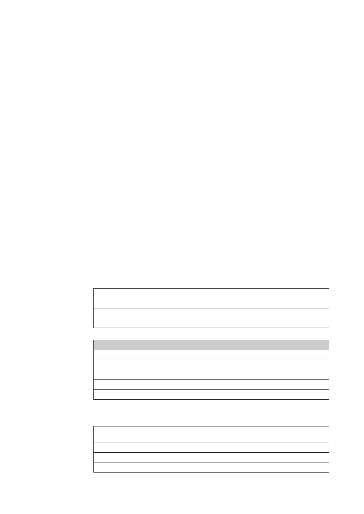
Current output 0/4 to 20 mA
Standard installation cable is sufficient.
Pulse/frequency/switch output
Standard installation cable is sufficient.
Double pulse output
Standard installation cable is sufficient.
Relay output
Standard installation cable is sufficient.
Current input 0/4 to 20 mA
Standard installation cable is sufficient.
Status input
Standard installation cable is sufficient.
Cable diameter
• Cable glands supplied:
M20 × 1.5 with cable ⌀ 6 to 12 mm (0.24 to 0.47 in)
• Spring terminals:
Conductor cross-section0.2 to 2.5 mm2 (24 to 12 AWG)
Connecting cable for sensor - transmitter: Proline 500 – digital
Non-hazardous area, Ex Zone 2, Class I, Division 2
Standard cable
A standard cable can be used as the connecting cable.
Standard cable 4 cores (2 pairs); twisted pair with common shield
Shielding Tin-plated copper-braid, optical cover ≥ 85 %
Loop resistance Power supply line (+, –): maximum 10 Ω
Cable length Maximum 300 m (1 000 ft), see the following table.
Cross-section Cable length
0.34 mm2 (AWG 22) 80 m (270 ft)
0.50 mm2 (AWG 20) 120 m (400 ft)
0.75 mm2 (AWG 18) 180 m (600 ft)
1.00 mm2 (AWG 17) 240 m (800 ft)
1.50 mm2 (AWG 15) 300 m (1 000 ft)
Optionally available connecting cable
Standard cable
Flame resistance According to DIN EN 60332-1-2
Oil-resistance According to DIN EN 60811-2-1
Shielding Tin-plated copper-braid, optical cover ≥ 85 %
2 × 2 × 0.34 mm2 (AWG 22) PVC cable with common shield (2 pairs, twisted
pair)
38 Endress+Hauser
Page 39
Proline Promass F 500 Modbus RS485 Electrical connection
A
B
A
B
A
B
Operating temperature When mounted in a fixed position: –50 to +105 °C (–58 to +221 °F); when cable
can move freely: –25 to +105 °C (–13 to +221 °F)
Available cable length Fixed: 20 m (65 ft); variable: up to maximum 50 m (165 ft)
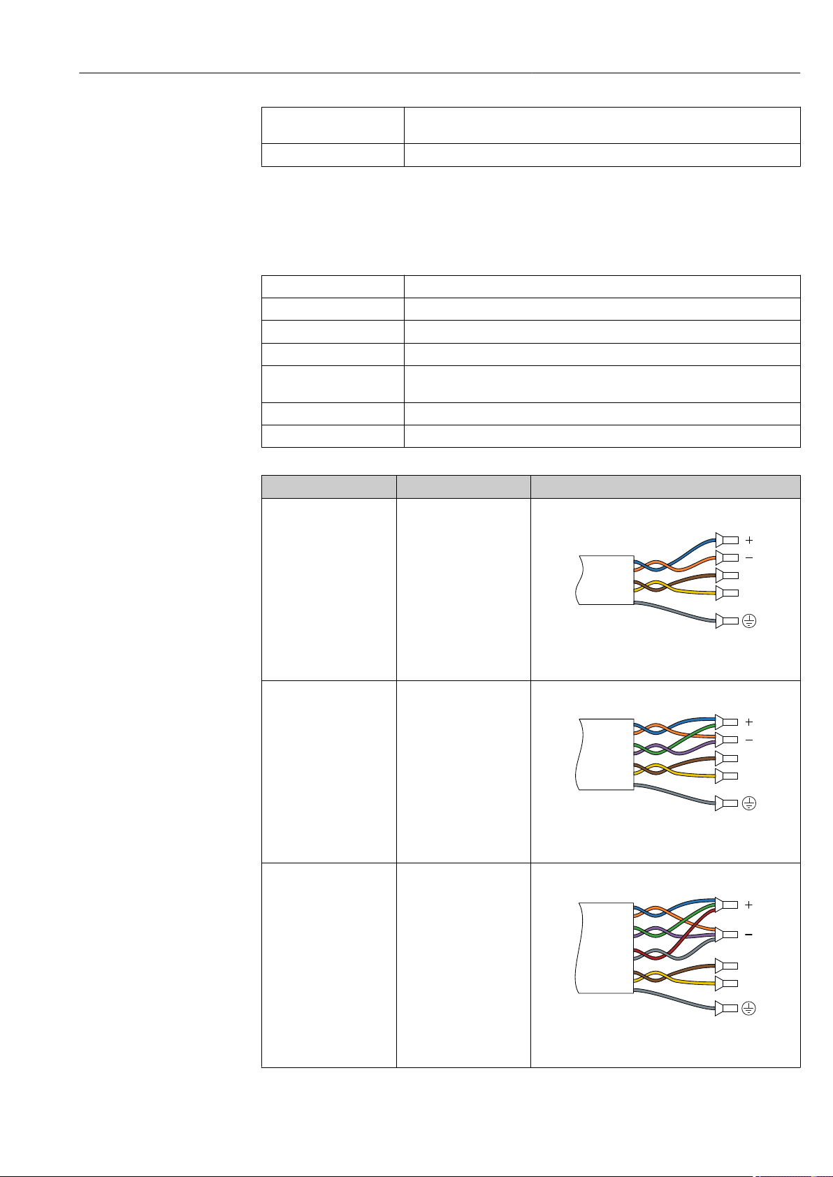
Hazardous area, Ex Zone 1, Class I, Division 1
Standard cable
A standard cable can be used as the connecting cable.
Standard cable 4, 6, 8 cores (2, 3, 4 pairs); twisted pair with common shield
Shielding Tin-plated copper-braid, optical cover ≥ 85 %
Capacitance C Maximum 730 nF IIC, maximum 4.2 µF IIB
Inductance L Maximum 26 µH IIC, maximum 104 µH IIB
Inductance/resistance
ratio (L/R)
Loop resistance Power supply line (+, –): maximum 5 Ω
Cable length Maximum 150 m (500 ft), see the following table.
Maximum 8.9 µH/Ω IIC, maximum 35.6 µH/Ω IIB (e.g. in accordance with IEC
60079-25)
Cross-section Cable length Assembly
2 x 2 x 0.50 mm
2
50 m (165 ft) 2 x 2 x 0.50 mm2 (AWG 22)
(AWG 22)
• +, – = 0.5 mm
• A, B = 0.5 mm
3 x 2 x 0.50 mm
2
100 m (330 ft) 3 x 2 x 0.50 mm2 (AWG 22)
(AWG 22)
• +, – = 1.0 mm
• A, B = 0.5 mm
4 x 2 x 0.50 mm
2
150 m (500 ft) 4 x 2 x 0.50 mm2 (AWG 22)
(AWG 22)
2
2
2
2
• +, – = 1.5 mm
• A, B = 0.5 mm
Endress+Hauser 39
2
2
Page 40
Electrical connection Proline Promass F 500 Modbus RS485
Optionally available connecting cable
Connecting cable for Ex Zone 1, Class I, Division 1, IIC, IIB
Standard cable
Flame resistance According to DIN EN 60332-1-2
Oil-resistance According to DIN EN 60811-2-1
Shielding Tin-plated copper-braid, optical cover ≥ 85 %
Operating temperature When mounted in a fixed position: –50 to +105 °C (–58 to +221 °F); when cable
Available cable length Fixed: 20 m (65 ft); variable: up to maximum 50 m (165 ft)
2 × 2 × 0.5 mm2 (AWG 20) PVC cable with common shield (2 pairs, twisted pair)
can move freely: –25 to +105 °C (–13 to +221 °F)
Connecting cable for sensor - Proline 500 transmitter
Standard cable
Conductor resistance ≤50 Ω/km (0.015 Ω/ft)
Capacitance: core/shield ≤420 pF/m (128 pF/ft)
Cable length (max.) 20 m (65 ft)
Cable lengths (available
for order)
Operating temperature max. 105 °C (221 °F)
6 × 0.38 mm2 PVC cable with common shield and individual shielded cores
5 m (15 ft), 10 m (32 ft), 20 m (65 ft)
Operation in zones of severe electrical interference
The measuring system meets the general safety requirements → 208 and EMC
specifications → 196.
Grounding is by means of the ground terminal provided for the purpose inside the
connection housing. The stripped and twisted lengths of cable shield to the ground
terminal must be as short as possible.
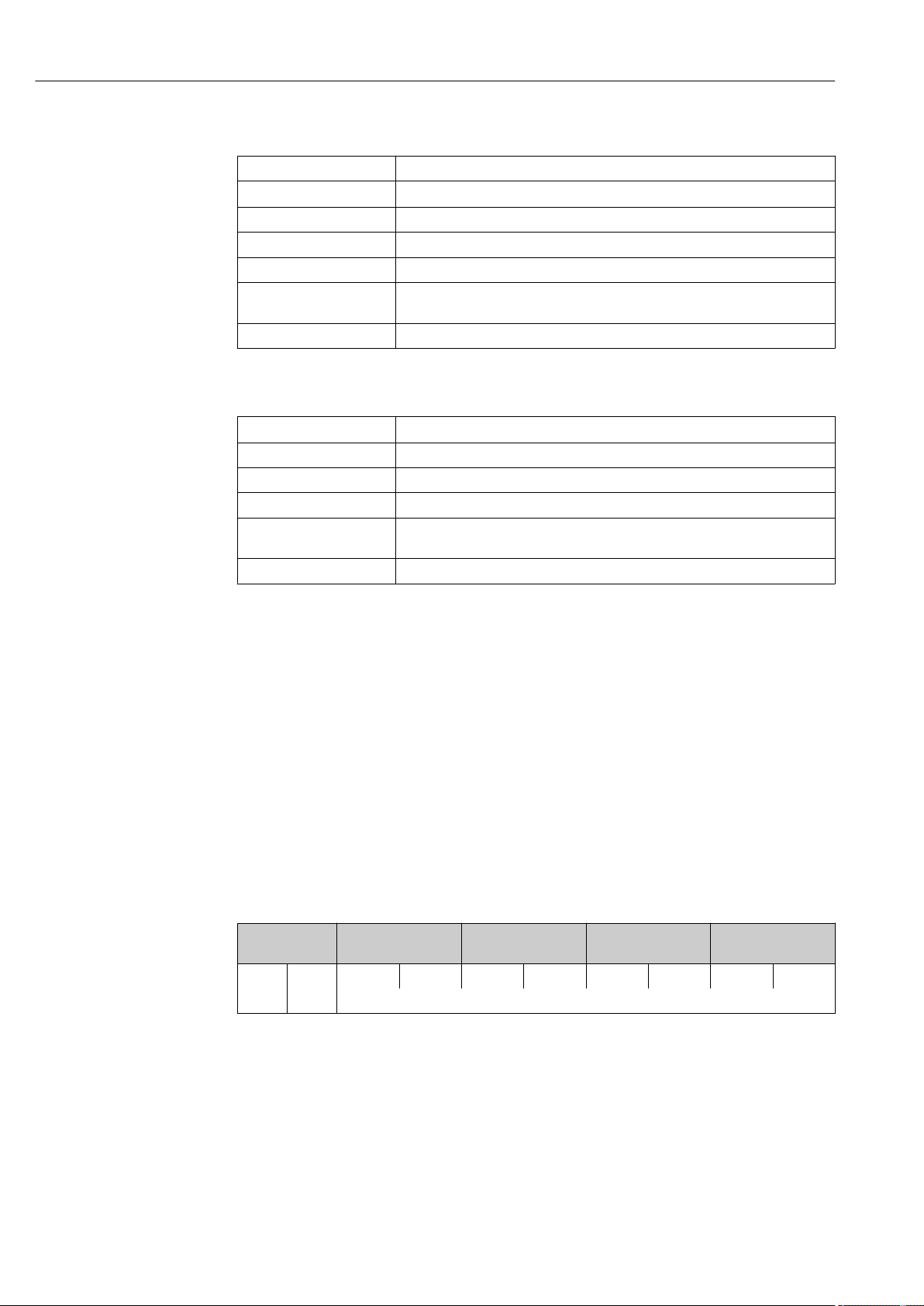
7.1.3 Terminal assignment
Transmitter: supply voltage, input/outputs
The terminal assignment of the inputs and outputs depends on the individual order
version of the device. The device-specific terminal assignment is documented on an
adhesive label in the terminal cover.
Supply voltage Input/output
1
1 (+) 2 (–) 26 (B) 27 (A) 24 (+) 25 (–) 22 (+) 23 (–) 20 (+) 21 (–)
Device-specific terminal assignment: adhesive label in terminal cover.
Input/output
2
Input/output
3
Input/output
4
Transmitter and sensor connection housing: connecting cable
The sensor and transmitter, which are mounted in separate locations, are interconnected
by a connecting cable. The cable is connected via the sensor connection housing and the
transmitter housing.
Terminal assignment and connection of the connecting cable:
• Proline 500 – digital→ 42
• Proline 500 → 49
40 Endress+Hauser
Page 41

Proline Promass F 500 Modbus RS485 Electrical connection
7.1.4 Preparing the measuring device
Carry out the steps in the following order:
1. Mount the sensor and transmitter.
2. Connection housing, sensor: Connect connecting cable.
3. Transmitter: Connect connecting cable.
4. Transmitter: Connect signal cable and cable for supply voltage.
NOTICE
Insufficient sealing of the housing!
Operational reliability of the measuring device could be compromised.
Use suitable cable glands corresponding to the degree of protection.
‣
1. Remove dummy plug if present.
2. If the measuring device is supplied without cable glands:
Provide suitable cable gland for corresponding connecting cable.
3. If the measuring device is supplied with cable glands:
Observe requirements for connecting cables → 37.
Endress+Hauser 41
Page 42
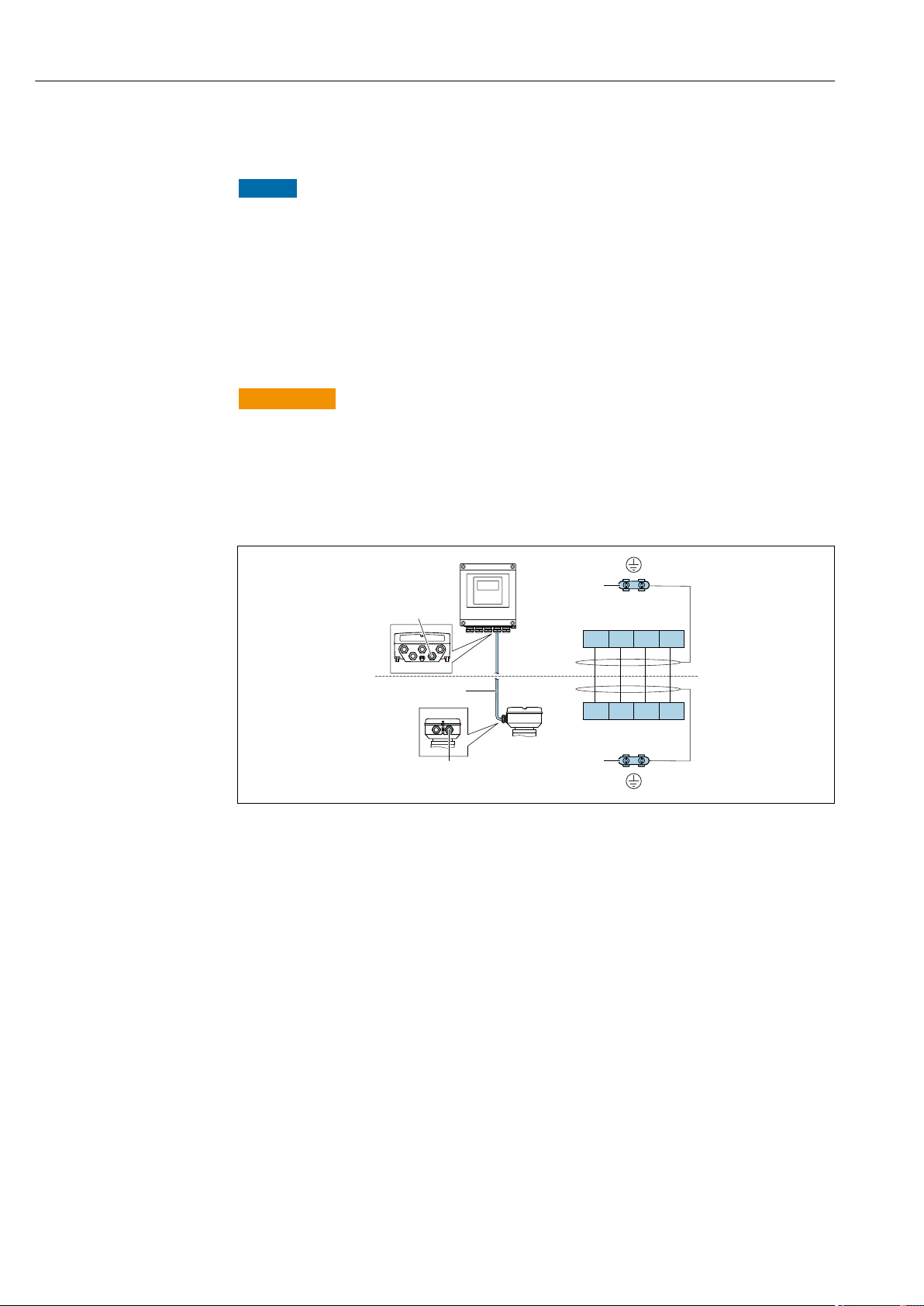
Electrical connection Proline Promass F 500 Modbus RS485
+ – AB
61 62 63 64
+ – AB
61 62 63 64
4
1
2
4
3
7.2 Connecting the measuring device: Proline 500 – digital
NOTICE
Limitation of electrical safety due to incorrect connection!
Have electrical connection work carried out by correspondingly trained specialists only.
‣
Observe applicable federal/national installation codes and regulations.
‣
Comply with local workplace safety regulations.
‣
Always connect the protective ground cable before connecting additional cables.
‣
For use in potentially explosive atmospheres, observe the information in the device-
‣
specific Ex documentation.
7.2.1 Connecting the connecting cable
WARNING
L
Risk of damaging the electronic components!
Connect the sensor and transmitter to the same potential equalization.
‣
Only connect the sensor to a transmitter with the same serial number.
‣
Ground the connection housing of the sensor via the external screw terminal.
‣
Terminal assignment
1 Cable entry for connecting cable on transmitter housing
2 Connecting cable ISEM communication
3 Cable entry for connecting cable or connector on sensor connection housing
4 Grounding via cable strain relief
Connecting the connecting cable to the sensor connection housing
• Connection via terminals with order code for "Sensor connection housing":
– Option A "Aluminum, coated"→ 43
– Option B "Stainless" → 44
– Option L "Cast, stainless"→ 43
• Connection via connectors with order code for "Sensor connection housing":
Option C "Ultra-compact hygienic, stainless"→ 45
A0028198
Connecting the connecting cable to the transmitter
The cable is connected to the transmitter via terminals → 46.
42 Endress+Hauser
Page 43
Proline Promass F 500 Modbus RS485 Electrical connection
2.
1.
3.
6.
5.
3 mm
10 (0.4)
TX 20TX 20
22 mm
7.
24 mm
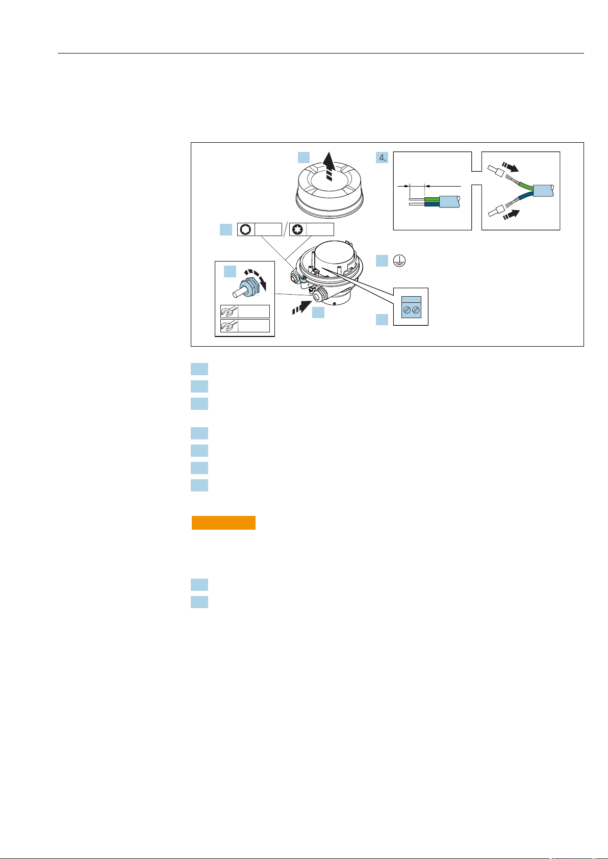
Connecting the sensor connection housing via terminals
For the device version with the order code for "Sensor connection housing":
• Option A "Aluminum coated"
• Option L "Cast, stainless"
1. Loosen the securing clamp of the housing cover.
2. Unscrew the housing cover.
3. Push the cable through the cable entry . To ensure tight sealing, do not remove the
sealing ring from the cable entry.
4. Strip the cable and cable ends. In the case of stranded cables, fit ferrules.
5. Connect the protective ground.
6. Connect the cable in accordance with the terminal assignment → 42.
7. Firmly tighten the cable glands.
This concludes the process for connecting the connecting cable.
WARNING
L
Housing degree of protection voided due to insufficient sealing of the housing.
Screw in the thread on the cover without using any lubricant. The thread on the cover is
‣
coated with a dry lubricant.
8. Screw on the housing cover.
9. Tighten the securing clamp of the housing cover.
A0029616
Endress+Hauser 43
Page 44
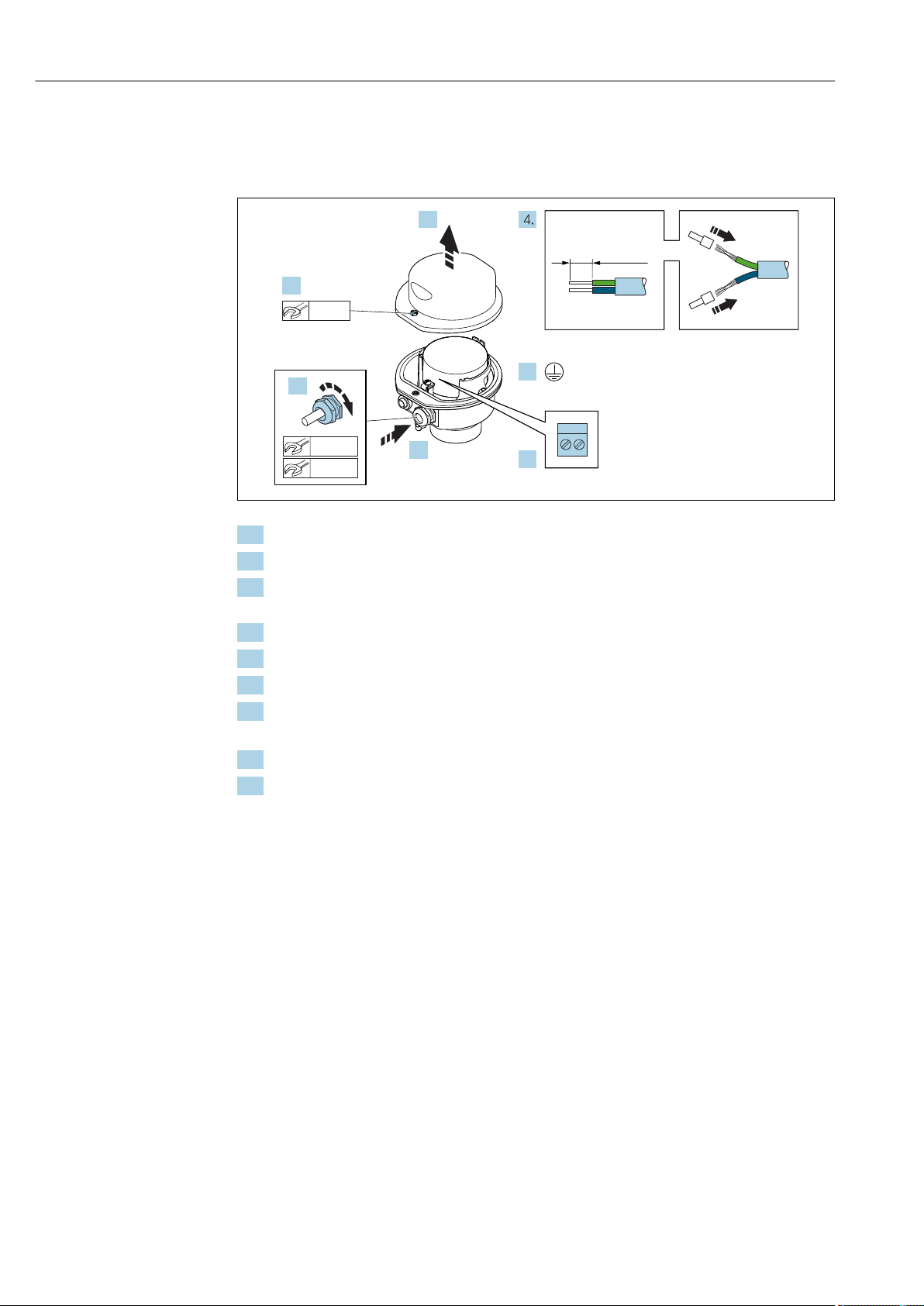
Electrical connection Proline Promass F 500 Modbus RS485
2.
1.
3.
6.
5.
10 (0.4)
8 mm
22 mm
7.
24 mm
Connecting the sensor connection housing via terminals
For the device version with the order code for "Sensor connection housing":
Option B "Stainless"
A0029613
1. Release the securing screw of the housing cover.
2. Open the housing cover.
3. Push the cable through the cable entry . To ensure tight sealing, do not remove the
sealing ring from the cable entry.
4. Strip the cable and cable ends. In the case of stranded cables, fit ferrules.
5. Connect the protective ground.
6. Connect the cable in accordance with the terminal assignment → 42.
7. Firmly tighten the cable glands.
This concludes the process for connecting the connecting cable.
8. Close the housing cover.
9. Tighten the securing screw of the housing cover.
44 Endress+Hauser
Page 45
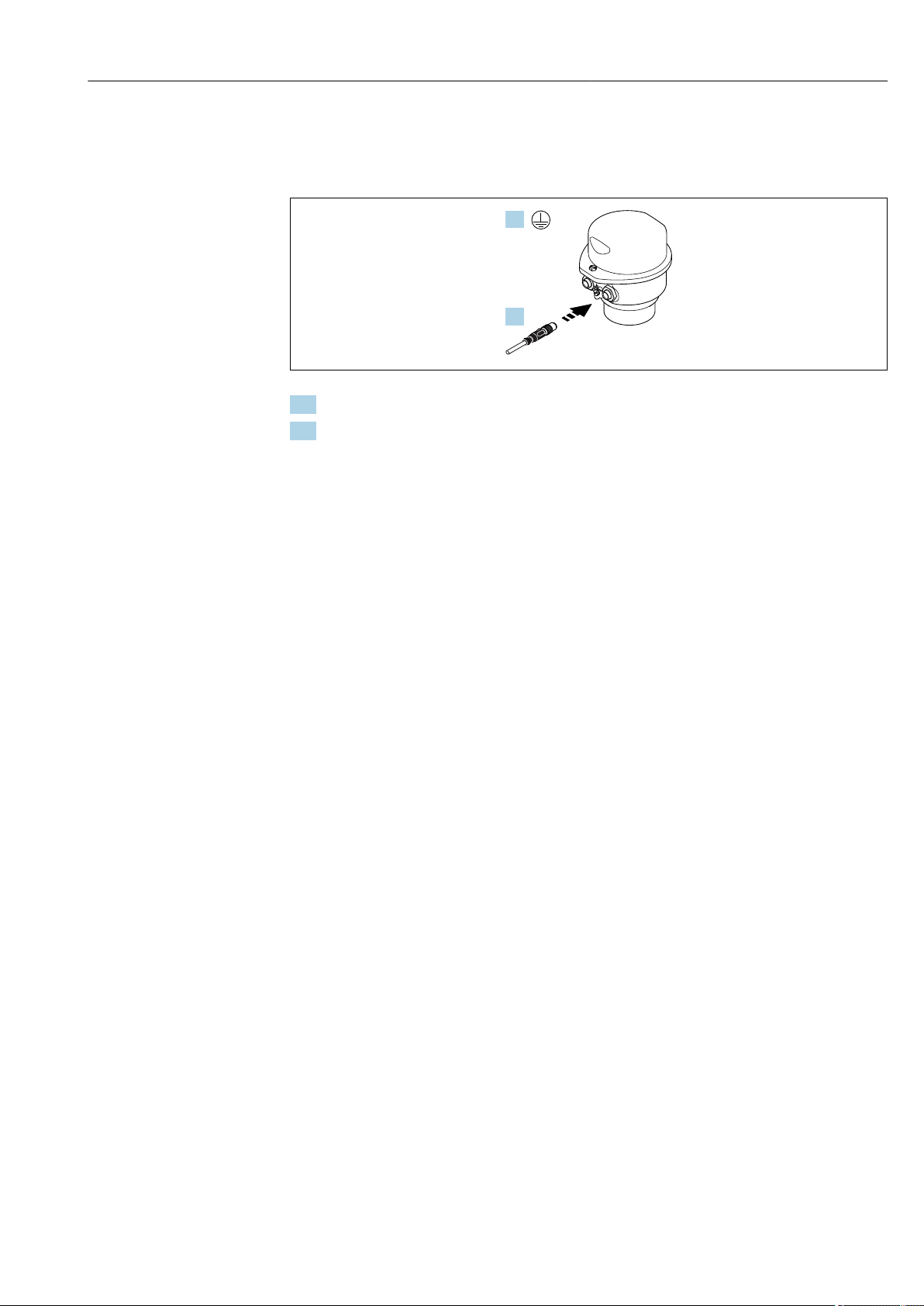
Proline Promass F 500 Modbus RS485 Electrical connection
1.
2.
Connecting the sensor connection housing via the connector
For the device version with the order code for "Sensor connection housing":
Option C "Ultra-compact hygienic, stainless"
A0029615
1. Connect the protective ground.
2. Connect the connector.
Endress+Hauser 45
Page 46
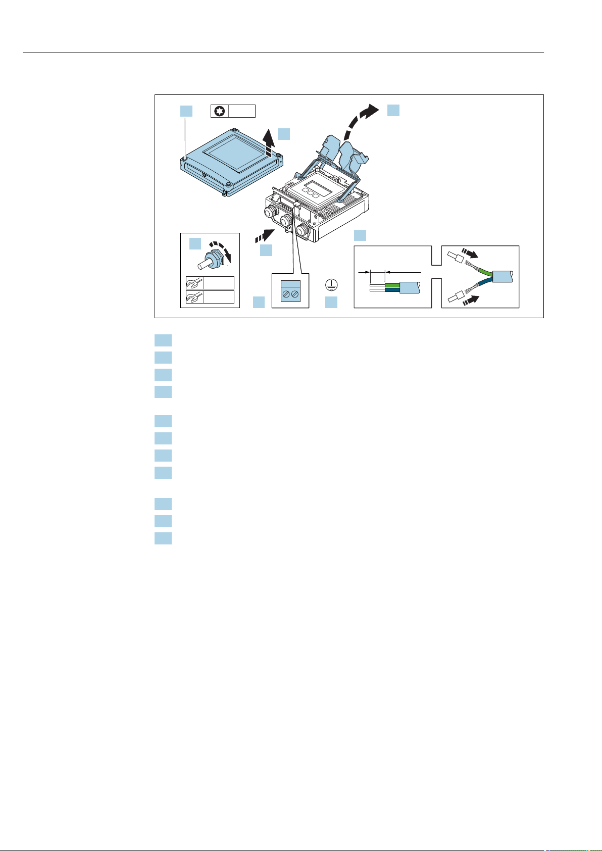
Electrical connection Proline Promass F 500 Modbus RS485
1.
3.
2.
4.
4 x
5.
7.
TX 20TX 20
6.
10 (0.4)
22 mm
8.
24 mm
Connecting the connecting cable to the transmitter
A0029597
1. Loosen the 4 fixing screws on the housing cover.
2. Open the housing cover.
3. Fold open the terminal cover.
4. Push the cable through the cable entry . To ensure tight sealing, do not remove the
sealing ring from the cable entry.
5. Strip the cable and cable ends. In the case of stranded cables, fit ferrules.
6. Connect the protective ground.
7. Connect the cable in accordance with the terminal assignment → 42.
8. Firmly tighten the cable glands.
This concludes the process for connecting the connecting cable.
9. Close the housing cover.
10. Tighten the securing screw of the housing cover.
11. After connecting the connecting cable:
Connect the signal cable and the supply voltage cable → 47.
46 Endress+Hauser
Page 47
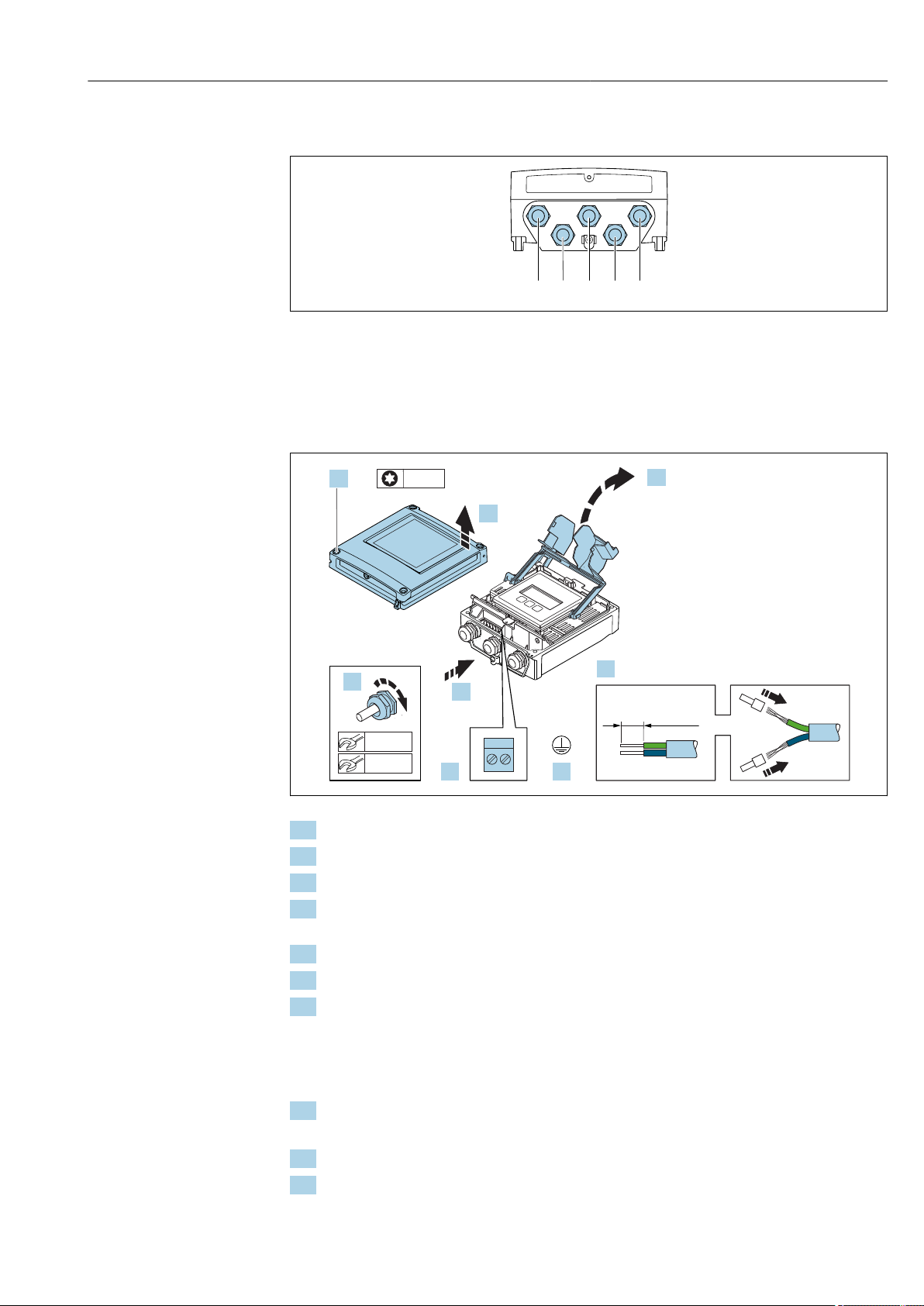
Proline Promass F 500 Modbus RS485 Electrical connection
1 2 3 4 5
1.
3.
2.
4.
4 x
5.
7.
TX 20TX 20
6.
10 (0.4)
22 mm
8.
24 mm
7.2.2 Connecting the signal cable and the supply voltage cable
A0028200
1 Cable entry for supply voltage
2 Cable entry for cable or connection of device plug for signal transmission
3 Cable entry for cable or connection of device plug for signal transmission
4 Cable entry for sensor - transmitter connecting cable
5 Cable entry for cable or connection of device plug for signal transmission, optional: connection of external
WLAN antenna or service connector
A0029597
1. Loosen the 4 fixing screws on the housing cover.
2. Open the housing cover.
3. Fold open the terminal cover.
4. Push the cable through the cable entry . To ensure tight sealing, do not remove the
sealing ring from the cable entry.
5. Strip the cable and cable ends. In the case of stranded cables, fit ferrules.
6. Connect the protective ground.
7. Connect the cable in accordance with the terminal assignment .
Signal cable terminal assignment: The device-specific terminal assignment is
documented on an adhesive label in the terminal cover.
Supply voltage terminal assignment: Adhesive label in the terminal cover or
→ 40.
8. Firmly tighten the cable glands.
This concludes the cable connection process.
9. Close the terminal cover.
10. Close the housing cover.
Endress+Hauser 47
Page 48
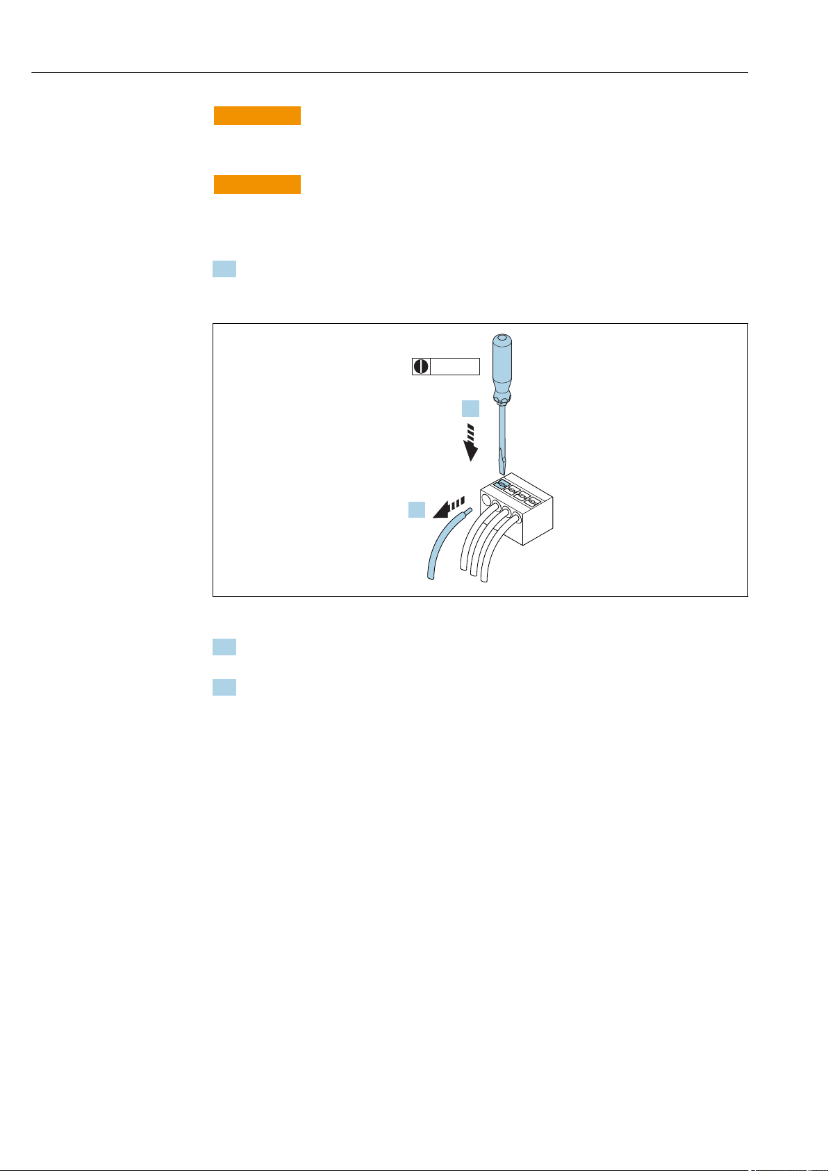
Electrical connection Proline Promass F 500 Modbus RS485
3 (0.12)
2.
1.
WARNING
L
Housing degree of protection may be voided due to insufficient sealing of the housing.
Screw in the screw without using any lubricant.
‣
WARNING
L
Excessive tightening torque applied to the fixing screws!
Risk of damaging the plastic transmitter.
Tighten the fixing screws as per the tightening torque: 2 Nm (1.5 lbf ft).
‣
11. Tighten the 4 fixing screws on the housing cover.
Removing a cable
A0029598
15 Engineering unit mm (in)
1. To remove a cable from the terminal, use a flat-blade screwdriver to push the slot
between the two terminal holes
2. while simultaneously pulling the cable end out of the terminal.
48 Endress+Hauser
Page 49
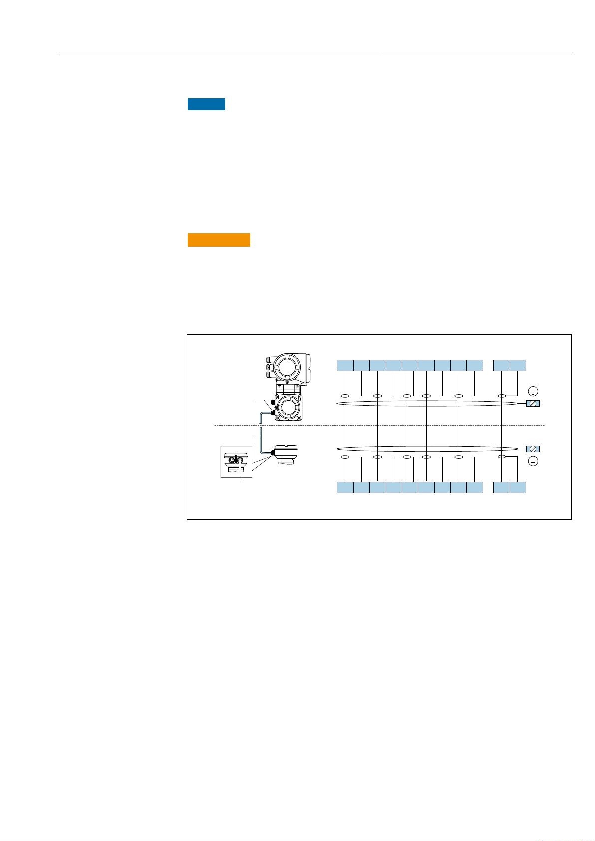
Proline Promass F 500 Modbus RS485 Electrical connection
4
5 6
7
8
11 12 41
42
S1 S1 S2 S2 GNDTM TM TT TT
+ + + +
+ + + +
S1 S1 S2 S2 GND TM TM TT TT
3
ER
+
+
ERERER
2
1
10
9
4 5 6 7 8 9 10 11 12 41 42
7.3 Connecting the measuring device: Proline 500
NOTICE
Limitation of electrical safety due to incorrect connection!
Have electrical connection work carried out by correspondingly trained specialists only.
‣
Observe applicable federal/national installation codes and regulations.
‣
Comply with local workplace safety regulations.
‣
Always connect the protective ground cable before connecting additional cables.
‣
For use in potentially explosive atmospheres, observe the information in the device-
‣
specific Ex documentation.
7.3.1 Connecting the connecting cable
WARNING
L
Risk of damaging the electronic components!
Connect the sensor and transmitter to the same potential equalization.
‣
Only connect the sensor to a transmitter with the same serial number.
‣
Ground the connection housing of the sensor via the external screw terminal.
‣
Terminal assignment
A0028197
1 Cable entry for connecting cable on transmitter connection housing
2 Connecting cable
3 Cable entry for connecting cable on sensor connection housing
Connecting the connecting cable to the sensor connection housing
Connection via terminals with order code for "Housing":
– Option B "Stainless"→ 51
– Option L "Cast, stainless"→ 50
Connecting the connecting cable to the transmitter
Endress+Hauser 49
The cable is connected to the transmitter via terminals → 52.
Page 50
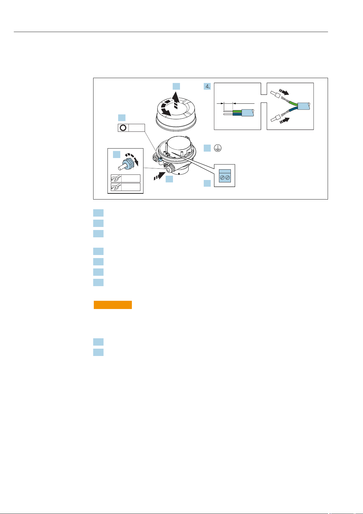
Electrical connection Proline Promass F 500 Modbus RS485
2.
1.
3.
6.
5.
3 mm
10 (0.4)
22 mm
7.
24 mm
Connecting the sensor connection housing via terminals
For the device version with the order code for "Housing":
Option L "Cast, stainless"
A0029612
1. Loosen the securing clamp of the housing cover.
2. Unscrew the housing cover.
3. Push the cable through the cable entry . To ensure tight sealing, do not remove the
sealing ring from the cable entry.
4. Strip the cable and cable ends. In the case of stranded cables, fit ferrules.
5. Connect the protective ground.
6. Connect the cable in accordance with the terminal assignment → 49.
7. Firmly tighten the cable glands.
This concludes the process for connecting the connecting cable.
WARNING
L
Housing degree of protection voided due to insufficient sealing of the housing.
Screw in the thread on the cover without using any lubricant. The thread on the cover is
‣
coated with a dry lubricant.
8. Screw on the housing cover.
9. Tighten the securing clamp of the housing cover.
50 Endress+Hauser
Page 51
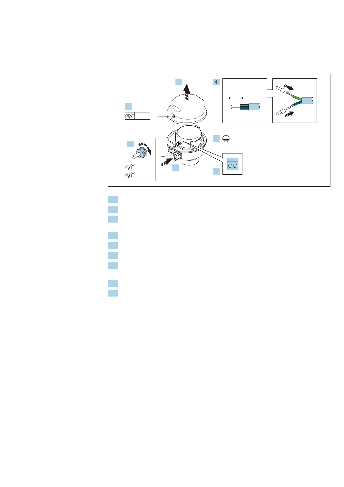
Proline Promass F 500 Modbus RS485 Electrical connection
2.
1.
3.
6.
5.
10 (0.4)
8 mm
22 mm
7.
24 mm
Connecting the sensor connection housing via terminals
For the device version with the order code for "Housing":
Option B "Stainless"
A0029613
1. Release the securing screw of the housing cover.
2. Open the housing cover.
3. Push the cable through the cable entry . To ensure tight sealing, do not remove the
sealing ring from the cable entry.
4. Strip the cable and cable ends. In the case of stranded cables, fit ferrules.
5. Connect the protective ground.
6. Connect the cable in accordance with the terminal assignment → 49.
7. Firmly tighten the cable glands.
This concludes the process for connecting the connecting cable.
8. Close the housing cover.
9. Tighten the securing screw of the housing cover.
Endress+Hauser 51
Page 52
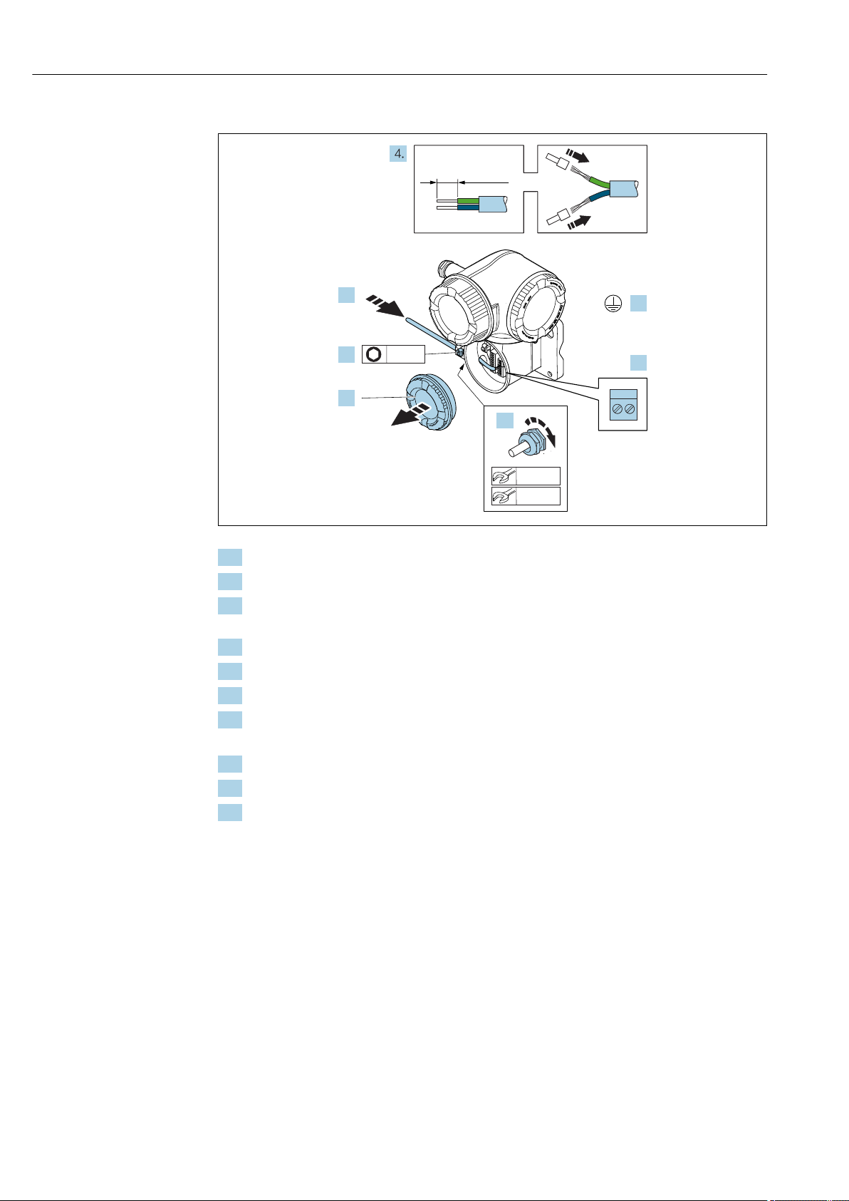
Electrical connection Proline Promass F 500 Modbus RS485
N
i
c
h
t
u
n
t
e
r
a
r
e
ö
f
f
n
e
n
N
i
c
h
t
u
n
t
e
r
c
i
r
c
u
i
t
s
a
r
e
a
l
i
v
e
1.
2.
3.
6.
5.
10 (0.4)
3 mm
22 mm
7.
24 mm
Connecting the connecting cable to the transmitter
A0029592
1. Loosen the securing clamp of the connection compartment cover.
2. Unscrew the connection compartment cover.
3. Push the cable through the cable entry . To ensure tight sealing, do not remove the
sealing ring from the cable entry.
4. Strip the cable and cable ends. In the case of stranded cables, also fit ferrules.
5. Connect the protective ground.
6. Connect the cable in accordance with the terminal assignment → 49.
7. Firmly tighten the cable glands.
This concludes the process for connecting the connecting cable.
8. Screw on the connection compartment cover.
9. Tighten the securing clamp of the connection compartment cover.
10. After connecting the connecting cable: After connecting the connecting cables:
Connect the signal cable and the supply voltage cable → 53.
52 Endress+Hauser
Page 53
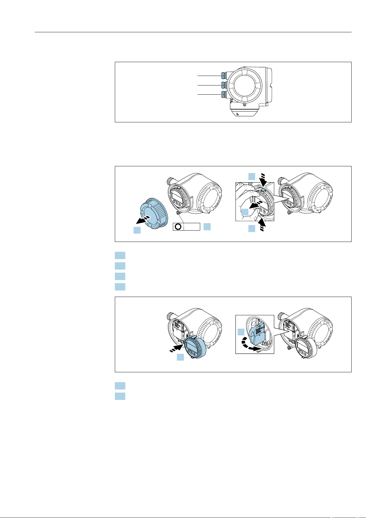
Proline Promass F 500 Modbus RS485 Electrical connection
2
3
N
i
c
h
t
u
n
t
e
r
a
r
e
ö
f
f
n
e
n
+
E
ESC
–
1.
2.
N
i
c
h
t
u
n
t
e
r
a
r
e
ö
f
f
n
e
n
+
E
ESC
–
+
E
ESC
–
3.
3.
4.
3 mm
N
i
c
h
t
u
n
t
e
r
a
r
e
ö
f
f
n
e
n
Nicht unter
Spannung öffnen
Do not open when
energized
Ne pas ouvrir
sous tension
Power
I/O
+
E
ESC
–
5.
N
i
c
h
t
u
n
t
e
r
a
r
e
ö
f
f
n
e
n
Nicht unter
Spannung öffnen
Do not open when
energized
Ne pas ouvrir
sous tension
Power
I/O
+
E
ESC
–
Power
Nicht unter
Spannung öffnen
Do not open when
energized
Ne pas ouvrir
sous tension
I/O
6.
7.3.2 Connecting the signal cable and the supply voltage cable
A0026781
1 Cable entry for supply voltage
2 Cable entry for signal transmission, input/output 1 and 2
3 Cable entry for input/output signal transmission; Optional: connection of external WLAN antenna or service
plug
1. Loosen the securing clamp of the connection compartment cover.
2. Unscrew the connection compartment cover.
3. Squeeze the tabs of the display module holder together.
4. Remove the display module holder.
5. Attach the holder to the edge of the electronics compartment.
6. Open the terminal cover.
A0029813
A0029814
Endress+Hauser 53
Page 54
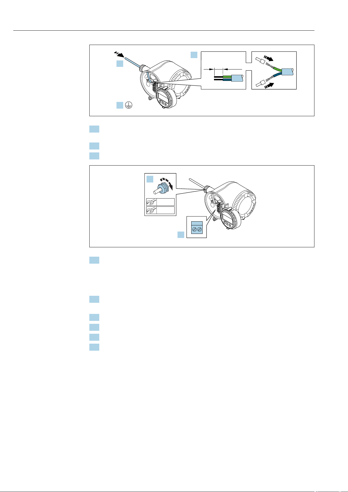
Electrical connection Proline Promass F 500 Modbus RS485
N
i
c
h
t
u
n
t
e
r
a
r
e
ö
f
f
n
e
n
+
E
ESC
–
10 (0.4)
mm (in)
7.
8.
9.
N
i
c
h
t
u
n
t
e
r
a
r
e
ö
f
f
n
e
n
+
E
ESC
–
10.
11.
22 mm
24 mm
A0029815
7. Push the cable through the cable entry . To ensure tight sealing, do not remove the
sealing ring from the cable entry.
8. Strip the cable and cable ends. In the case of stranded cables, also fit ferrules.
9. Connect the protective ground.
10. Connect the cable in accordance with the terminal assignment .
Signal cable terminal assignment: The device-specific terminal assignment is
documented on an adhesive label in the terminal cover.
Supply voltage terminal assignment: Adhesive label in the terminal cover or
→ 40.
11. Firmly tighten the cable glands.
This concludes the cable connection process.
12. Close the terminal cover.
13. Fit the display module holder in the electronics compartment.
14. Screw on the connection compartment cover.
15. Secure the securing clamp of the connection compartment cover.
A0029816
54 Endress+Hauser
Page 55
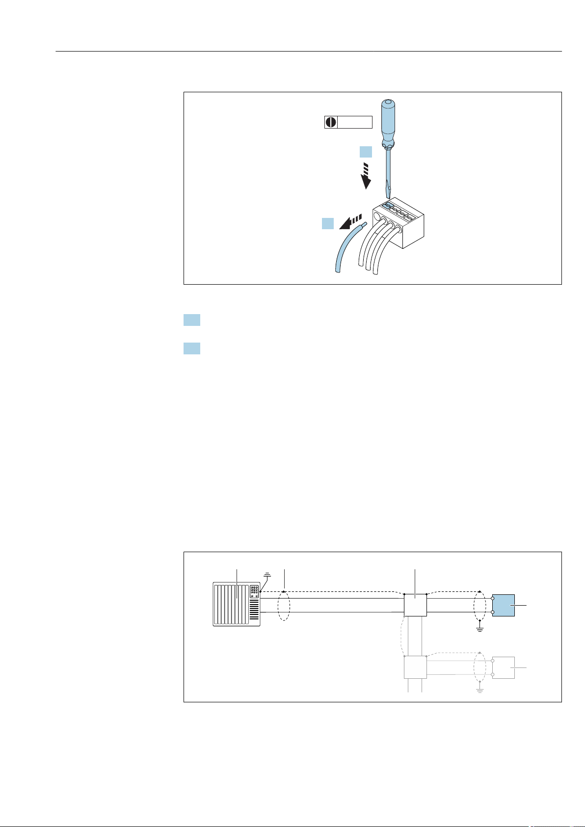
Proline Promass F 500 Modbus RS485 Electrical connection
3 (0.12)
2.
1.
2
1
A
B
3
4
4
A
B
A
B
Removing a cable
A0029598
16 Engineering unit mm (in)
1. To remove a cable from the terminal, use a flat-blade screwdriver to push the slot
between the two terminal holes
2. while simultaneously pulling the cable end out of the terminal.
7.4 Ensure potential equalization
7.4.1 Requirements
No special measures for potential equalization are required.
7.5 Special connection instructions
7.5.1 Connection examples
Modbus RS485
Endress+Hauser 55
17 Connection example for Modbus RS485, non-hazardous area and Zone 2/Div. 2
1 Control system (e.g. PLC)
2 Cable shield: the cable shield must be grounded at both ends to comply with EMC requirements; observe cable
specifications
3 Distribution box
4 Transmitter
A0028765
Page 56
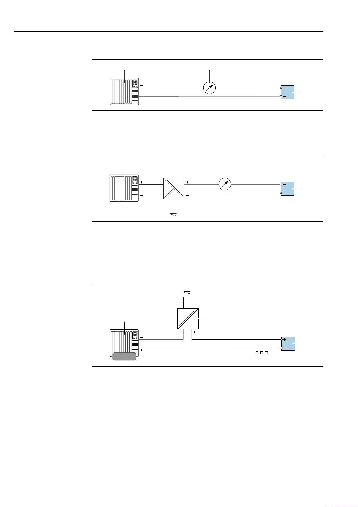
Electrical connection Proline Promass F 500 Modbus RS485
4...20 mA
2
1
3
2
4...20 mA
3
1
4
1
2
3
12345
Current output 4-20 mA
A0028758
18 Connection example for 4-20 mA current output (active)
1 Automation system with current input (e.g. PLC)
2 Analog display unit: observe maximum load
3 Transmitter
19 Connection example for 4-20 mA current output (passive)
1 Automation system with current input (e.g. PLC)
2 Active barrier for power supply (e.g. RN221N)
3 Analog display unit: observe maximum load
4 Transmitter
Pulse/frequency output
20 Connection example for pulse/frequency output (passive)
1 Automation system with pulse/frequency input (e.g. PLC)
2 Power supply
3 Transmitter: Observe input values → 185
A0028759
A0028761
56 Endress+Hauser
Page 57
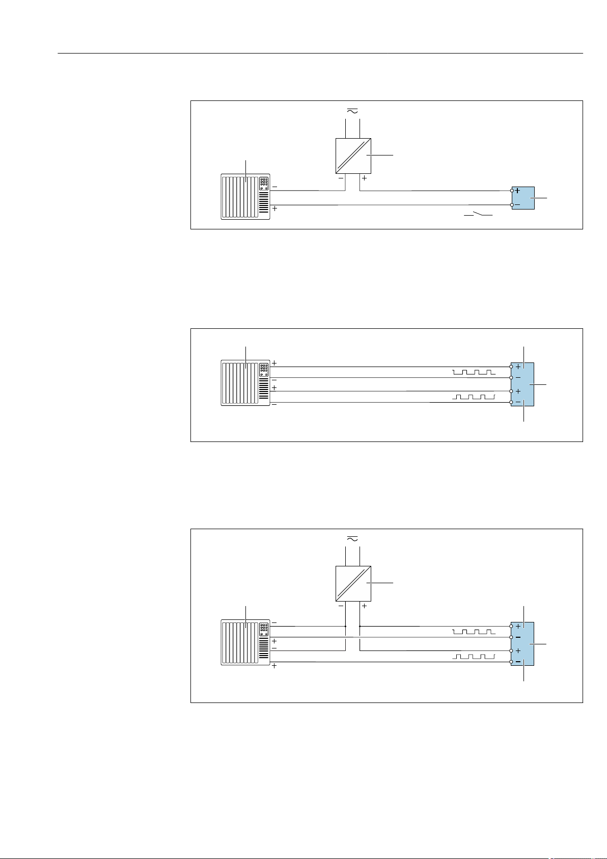
Proline Promass F 500 Modbus RS485 Electrical connection
1
2
3
1
2
3
4
1
3
2
4
5
Switch output
A0028760
21 Connection example for switch output (passive)
1 Automation system with switch input (e.g. PLC)
2 Power supply
3 Transmitter: Observe input values → 185
Double pulse output
A0029280
22 Connection example for double pulse output (active)
1 Automation system with double pulse input (e.g. PLC)
2 Transmitter: Observe input values → 186
3 Double pulse output
4 Double pulse output (slave), phase-shifted
A0029279
23 Connection example for double pulse output (passive)
1 Automation system with double pulse input (e.g. PLC)
2 Power supply
3 Transmitter: Observe input values → 186
4 Double pulse output
5 Double pulse output (slave), phase-shifted
Endress+Hauser 57
Page 58
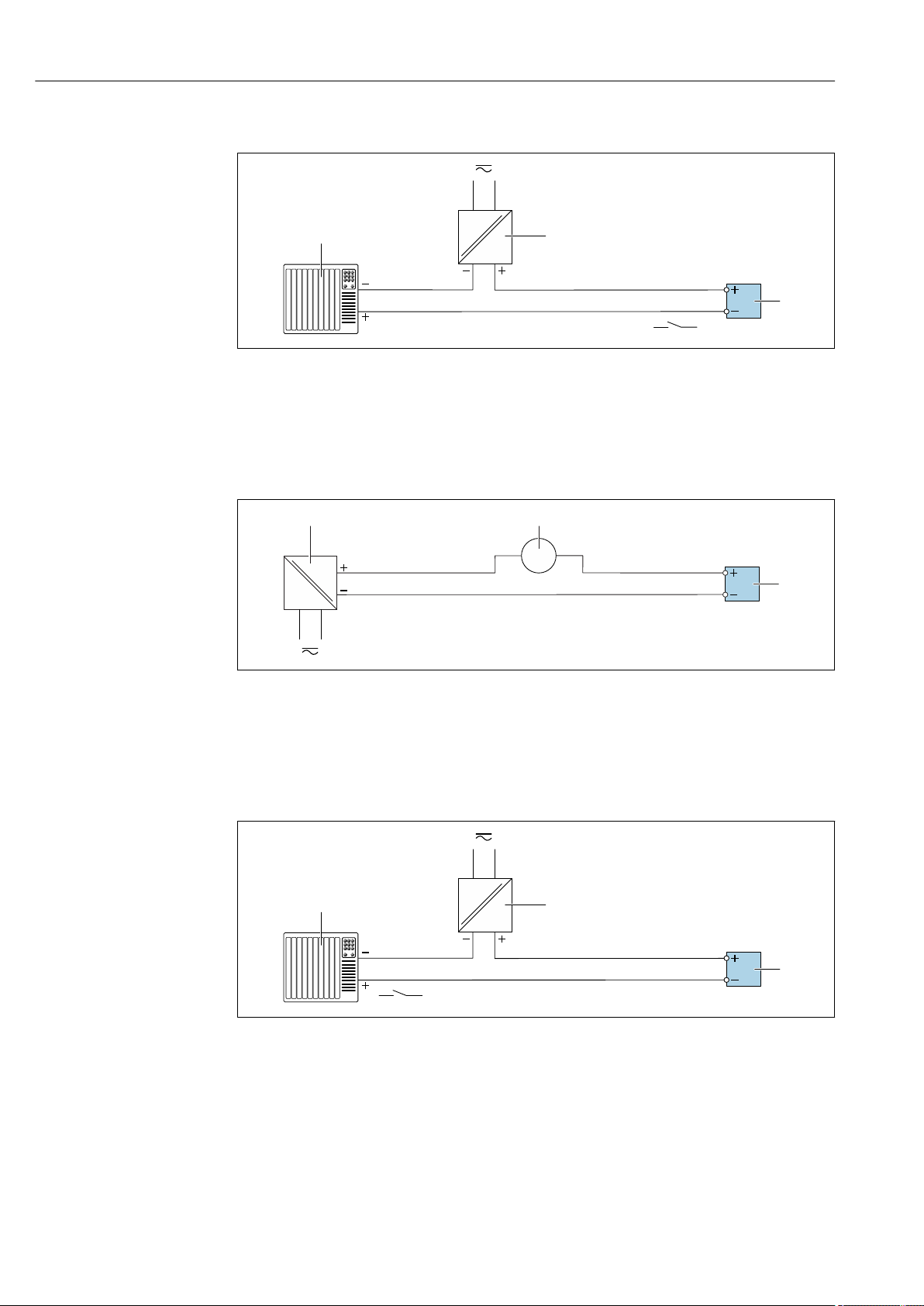
Electrical connection Proline Promass F 500 Modbus RS485
1
2
3
21
3
1
2
3
Relay output
A0028760
24 Connection example for relay output (passive)
1 Automation system with relay input (e.g. PLC)
2 Power supply
3 Transmitter: Observe input values → 187
Current input
25 Connection example for 4 to 20 mA current input
1 Power supply
2 External measuring device (for reading in pressure or temperature, for instance)
3 Transmitter: Observe input values
Status input
26 Connection example for status input
1 Automation system with status output (e.g. PLC)
2 Power supply
3 Transmitter: Observe input values
A0028915
A0028764
58 Endress+Hauser
Page 59
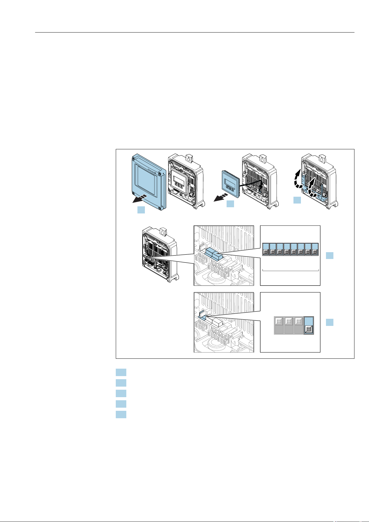
Proline Promass F 500 Modbus RS485 Electrical connection
Power
I/O 2
I/O 3
I/O 3
4.
1
2 3
4
567
8
128
64
32
16
8
4
2
1
Modbus address
Off
On
1 2
3
4
5.
3.
-
+
-
ESC
2.
Power
open
press
open
press
ESC
E+
-
I/O 4
Power
I/O 2
I/O 3
1.
7.6 Hardware settings
7.6.1 Setting the device address
The device address must always be configured for a Modbus slave. The valid device
addresses are in the range from 1 to 247. Each address may only be assigned once in a
Modbus RS485 network. If an address is not configured correctly, the measuring device is
not recognized by the Modbus master. All measuring devices are delivered from the
factory with the device address 247 and with the "software addressing" address mode.
Proline 500 – digital transmitter
Hardware addressing
1. Open the housing cover.
A0029677
2. Remove the display module.
3. Fold open the terminal cover.
4. Set the desired device address using the DIP switches.
5. To switch addressing from software addressing to hardware addressing: set the DIP
switch to On.
The change of device address takes effect after 10 seconds.
Software addressing
‣
To switch addressing from hardware addressing to software addressing: set the DIP
switch to Off.
The device address configured in the Device address parameter takes effect after
10 seconds.
Endress+Hauser 59
Page 60
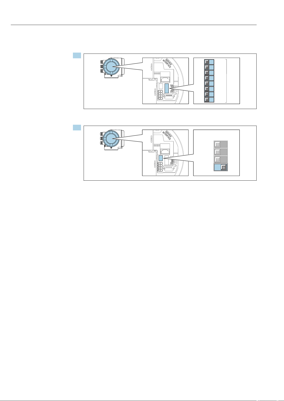
Electrical connection Proline Promass F 500 Modbus RS485
1
2
3
4
5
6
7
8
128
64
32
16
8
4
2
1
Modbus address
On
Off
2
3
1
4
Proline 500 transmitter
Hardware addressing
1.
A0029634
Set the desired device address using the DIP switches in the connection compartment.
2.
A0029633
To switch addressing from software addressing to hardware addressing: set the DIP
switch to On.
The change of device address takes effect after 10 seconds.
Software addressing
To switch addressing from hardware addressing to software addressing: set the DIP
‣
switch to Off.
The device address configured in the Device address parameter takes effect after
10 seconds.
7.6.2 Enabling the terminating resistor
To avoid incorrect communication transmission caused by impedance mismatch, terminate
the Modbus RS485 cable correctly at the start and end of the bus segment.
60 Endress+Hauser
Page 61
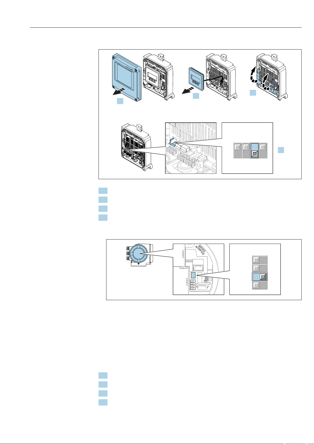
Proline Promass F 500 Modbus RS485 Electrical connection
Power
I/O 2
I/O 3
I/O 3
Off
On
1 2
3
4
4.
3.
-
+
-
ESC
2.
Power
open
press
open
press
ESC
E+
-
I/O 4
Power
I/O 2
I/O 3
1.
On
Off
2
1
4
3
Proline 500 – digital transmitter
A0029675
1. Open the housing cover.
2. Remove the display module.
3. Fold open the terminal cover.
4. Switch DIP switch No. 3 to On.
Proline 500 transmitter
‣
A0029632
Switch DIP switch No. 3 to On.
Endress+Hauser 61
7.7 Ensuring the degree of protection
The measuring device fulfills all the requirements for the IP66/67 degree of protection,
Type 4X enclosure.
To guarantee IP66/67 degree of protection, Type 4X enclosure, carry out the following
steps after the electrical connection:
1. Check that the housing seals are clean and fitted correctly.
2. Dry, clean or replace the seals if necessary.
3. Tighten all housing screws and screw covers.
4. Firmly tighten the cable glands.
Page 62
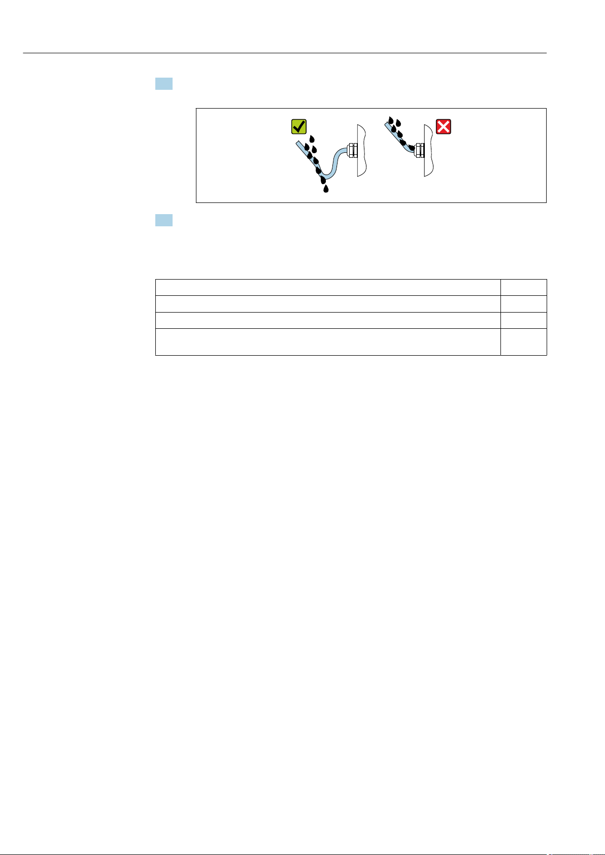
Electrical connection Proline Promass F 500 Modbus RS485
5. To ensure that moisture does not enter the cable entry:
Route the cable so that it loops down before the cable entry ("water trap").
A0029278
6. Insert dummy plugs into unused cable entries.
7.8 Post-connection check
Are cables or the device undamaged (visual inspection)?
Do the cables used meet the requirements?
Do the cables have adequate strain relief?
Are all the cable glands installed, firmly tightened and leak-tight? Cable run with "water trap"
→ 61 ?
62 Endress+Hauser
Page 63
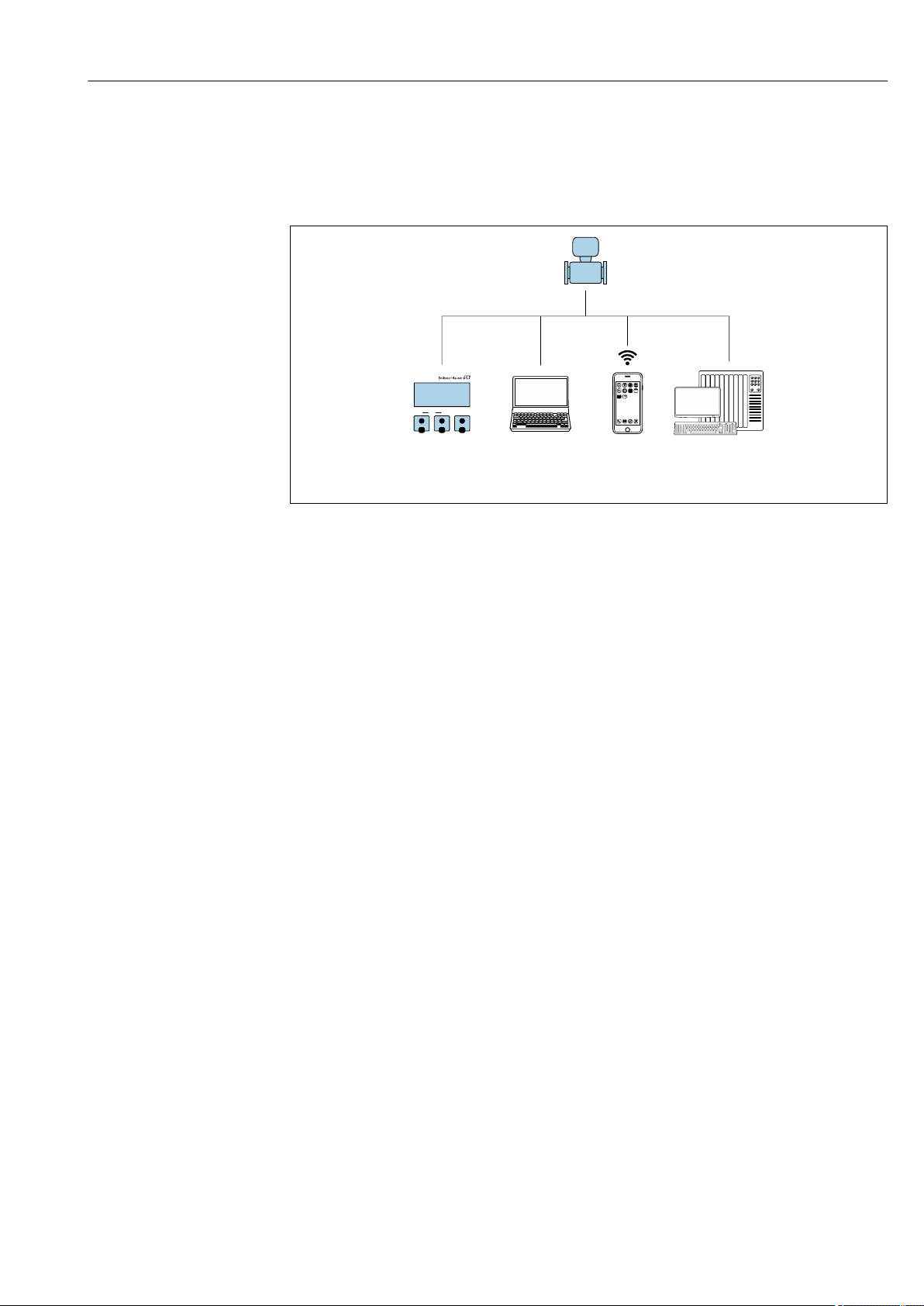
Proline Promass F 500 Modbus RS485 Operation options
1
2 3 4
E+-
ESC
8 Operation options
8.1 Overview of operation options
A0030213
1 Local operation via display module
2 Computer with Web browser (e.g. Internet Explorer) or with operating tool (e.g. FieldCare, DeviceCare, AMS
Device Manager, SIMATIC PDM)
3 Mobile handheld terminal
4 Control system (e.g. PLC)
Endress+Hauser 63
Page 64
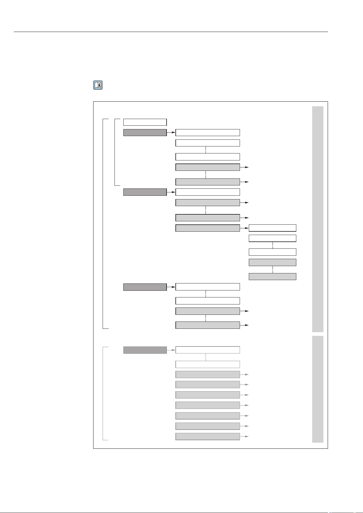
Operation options Proline Promass F 500 Modbus RS485
!
Expert
System
Sensor
Communication
Application
Diagnostics
Access status display
Output
Operating menu for experts
Language
Operatation Language
Parameter 1
Setup
Submenu 1
Submenu n
Device tag
Advanced setup
Enter access code
Parameter 1
Parameter n
Submenu 1
Submenu n
Diagnostics
Parameter 1
Parameter n
Submenu 1
Submenu n
Operating menu for operators and maintenances
Parameter n
Operator
Maintenance
Task-oriented
Function-oriented
Expert
Wizard 1 / Parameter 1
Wizard n / Parameter n
Parameter n
Input
8.2 Structure and function of the operating menu
8.2.1 Structure of the operating menu
For an overview of the operating menu for experts: "Description of Device Parameters"
document supplied with the device→ 210
64 Endress+Hauser
27 Schematic structure of the operating menu
A0018237-EN
Page 65
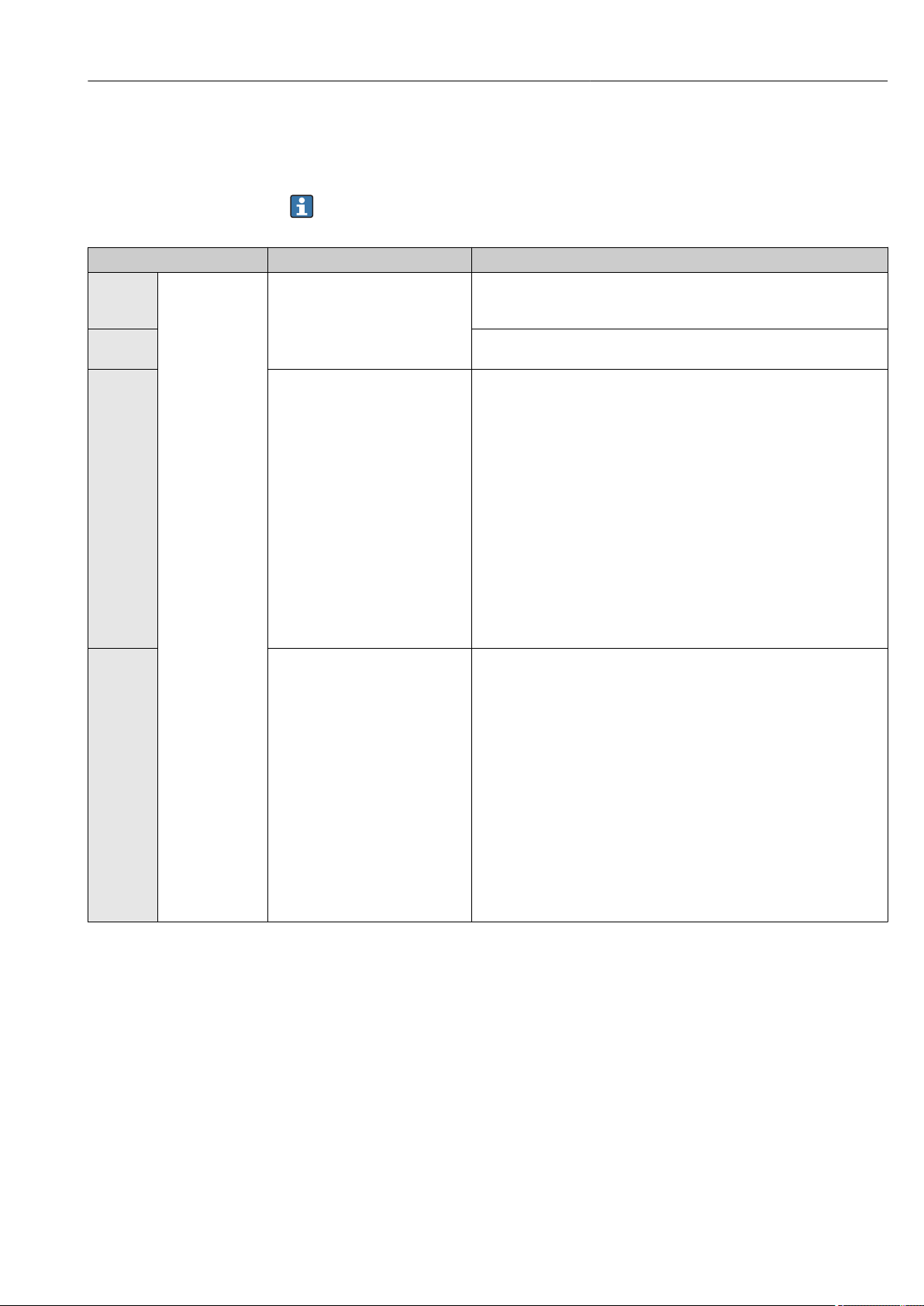
Proline Promass F 500 Modbus RS485 Operation options
8.2.2 Operating philosophy
The individual parts of the operating menu are assigned to certain user roles (operator,
maintenance etc.). Each user role contains typical tasks within the device lifecycle.
For custody transfer, once the device has been put into circulation or sealed, its
operation is restricted.
Menu/parameter User role and tasks Content/meaning
Language task-oriented Role "Operator", "Maintenance"
Tasks during operation:
• Configuring the operational
Operation • Configuring the operational display (e.g. display format, display contrast)
Setup "Maintenance" role
Diagnostics "Maintenance" role
display
• Reading measured values
Commissioning:
• Configuration of the
measurement
• Configuration of the inputs and
outputs
• Configuration of the
communication interface
Fault elimination:
• Diagnostics and elimination of
process and device errors
• Measured value simulation
• Defining the operating language
• Defining the Web server operating language
• Resetting and controlling totalizers
• Resetting and controlling totalizers
Wizards for fast commissioning:
• Set the system units
• Configuration of the communication interface
• Define the medium
• Display I/O/configuration
• Configure the inputs
• Configure the outputs
• Configuring the operational display
• Define the output conditioning
• Set the low flow cut off
• Configure partial and empty pipe detection
Advanced setup
• For more customized configuration of the measurement (adaptation to
special measuring conditions)
• Configuration of totalizers
• Configure the WLAN settings
• Administration (define access code, reset measuring device)
Contains all parameters for error detection and analyzing process and device
errors:
• Diagnostic list
Contains up to 5 currently pending diagnostic messages.
• Event logbook
Contains event messages that have occurred.
• Device information
Contains information for identifying the device.
• Measured values
Contains all current measured values.
• Data logging submenu with "Extended HistoROM" order option
Storage and visualization of measured values
• Heartbeat
The functionality of the device is checked on demand and the verification
results are documented.
• Simulation
Is used to simulate measured values or output values.
Endress+Hauser 65
Page 66
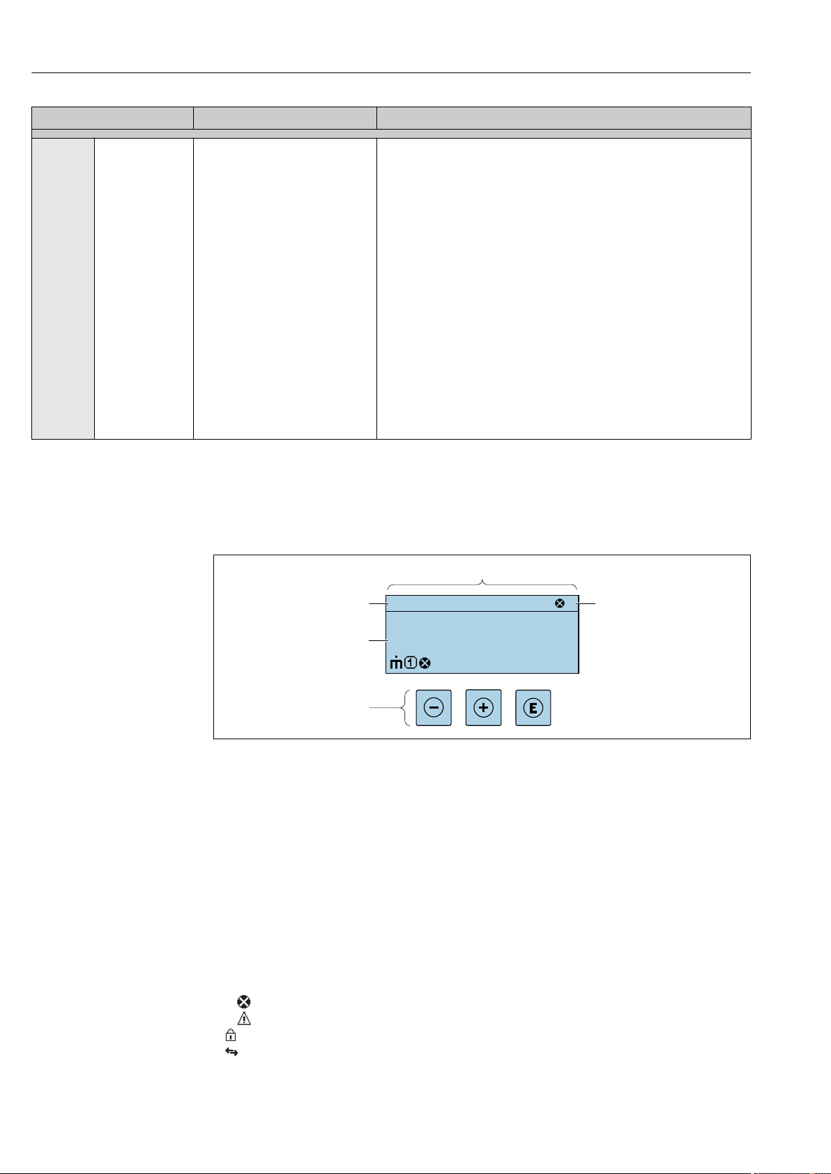
Operation options Proline Promass F 500 Modbus RS485
X X XX X XXX X
1
3
kg/h
1120.50
F
Menu/parameter User role and tasks Content/meaning
Expert function-oriented Tasks that require detailed
knowledge of the function of the
device:
• Commissioning measurements
under difficult conditions
• Optimal adaptation of the
measurement to difficult
conditions
• Detailed configuration of the
communication interface
• Error diagnostics in difficult cases
8.3 Access to the operating menu via the local display
8.3.1 Operational display
Contains all the parameters of the device and makes it possible to access
these parameters directly using an access code. The structure of this menu is
based on the function blocks of the device:
• System
Contains all higher-order device parameters which do not concern the
measurement or the communication interface.
• Sensor
Configuration of the measurement.
• Input
Configuring the status input.
• Output
Configuring of the analog current outputs as well as the pulse/frequency
and switch output.
• Communication
Configuration of the digital communication interface and the Web server.
• Application
Configure the functions that go beyond the actual measurement (e.g.
totalizer).
• Diagnostics
Error detection and analysis of process and device errors and for device
simulation and Heartbeat Technology.
A0029348
1 Operational display
2 Device tag
3 Status area
4 Display area for measured values (4-line)
5 Operating elements→ 71
Status area
The following symbols appear in the status area of the operational display at the top right:
• Status signals→ 158
– F: Failure
– C: Function check
– S: Out of specification
– M: Maintenance required
• Diagnostic behavior→ 159
– : Alarm
– : Warning
• : Locking (the device is locked via the hardware )
• : Communication (communication via remote operation is active)
66 Endress+Hauser
Page 67
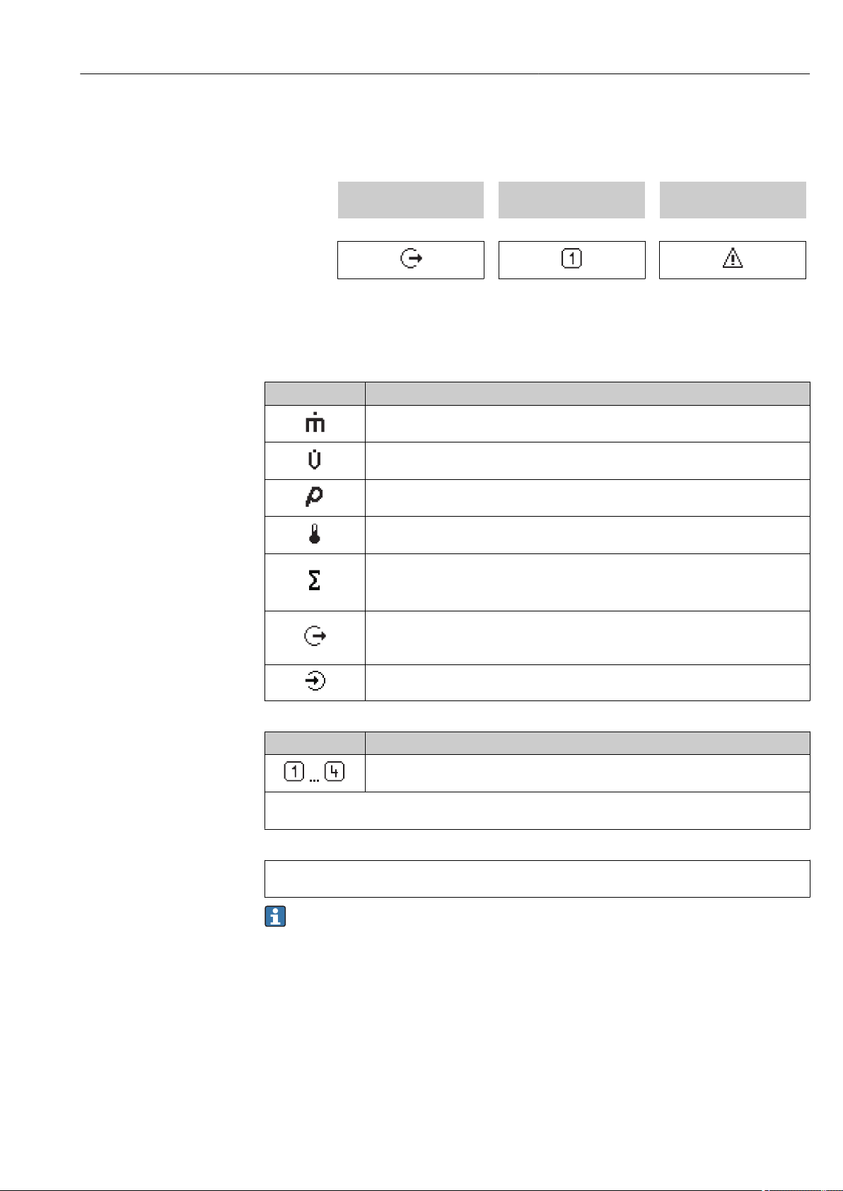
Proline Promass F 500 Modbus RS485 Operation options
Display area
In the display area, each measured value is prefaced by certain symbol types for further
description:
Measured variable Measurement channel
Example
Measured values
Symbol Meaning
Mass flow
• Volume flow
• Corrected volume flow
• Density
• Reference density
Temperature
Totalizer
Output
Diagnostic behavior
number
↓ ↓ ↓
Appears only if a diagnostics
event is present for this
measured variable.
The measurement channel number indicates which of the three totalizers is
displayed.
The measurement channel number indicates which of the outputs is displayed.
Status input
Measurement channel numbers
Symbol Meaning
Measurement channel 1 to 4
The measurement channel number is displayed only if more than one channel is present for the same measured
variable type (e.g. Totalizer 1 to 3).
Diagnostic behavior
The diagnostic behavior pertains to a diagnostic event that is relevant to the displayed measured variable.
For information on the symbols → 159
The number and display format of the measured values can be configured via the
"Format display" parameter → 117. Operation → Display → Format display
Endress+Hauser 67
Page 68
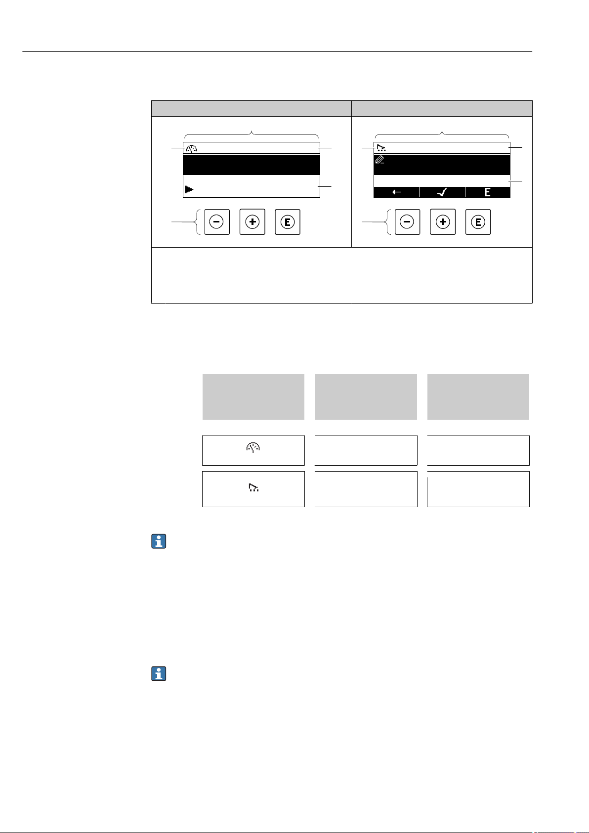
Operation options Proline Promass F 500 Modbus RS485
4
1
3
/../Operation
0091-1
Access stat.disp
Operator
Locking status
Display
4
1
3
/../Select medium
Select medium
Liquid
8.3.2 Navigation view
In the submenu In the wizard
A0013993-EN
1
Navigation view
2
Navigation path to current position
3
Status area
4
Display area for navigation
5
Operating elements → 71
Navigation path
The navigation path - displayed at the top left in the navigation view - consists of the
following elements:
• In the submenu:
Display symbol for menu
• In the wizard:
Display symbol for wizard
↓ ↓ ↓
Examples / ../ Display
Omission symbol for
operating menu levels in
between
/ ../ Display
Name of current
• Submenu
• Wizard
• Parameters
A0013995-EN
For more information about the icons in the menu, refer to the "Display area" section
→ 69
Status area
The following appears in the status area of the navigation view in the top right corner:
• In the submenu
– The direct access code for the parameter you are navigating to (e.g. 0022-1)
– If a diagnostic event is present, the diagnostic behavior and status signal
• In the wizard
If a diagnostic event is present, the diagnostic behavior and status signal
• For information on the diagnostic behavior and status signal → 158
• For information on the function and entry of the direct access code → 74
68 Endress+Hauser
Page 69
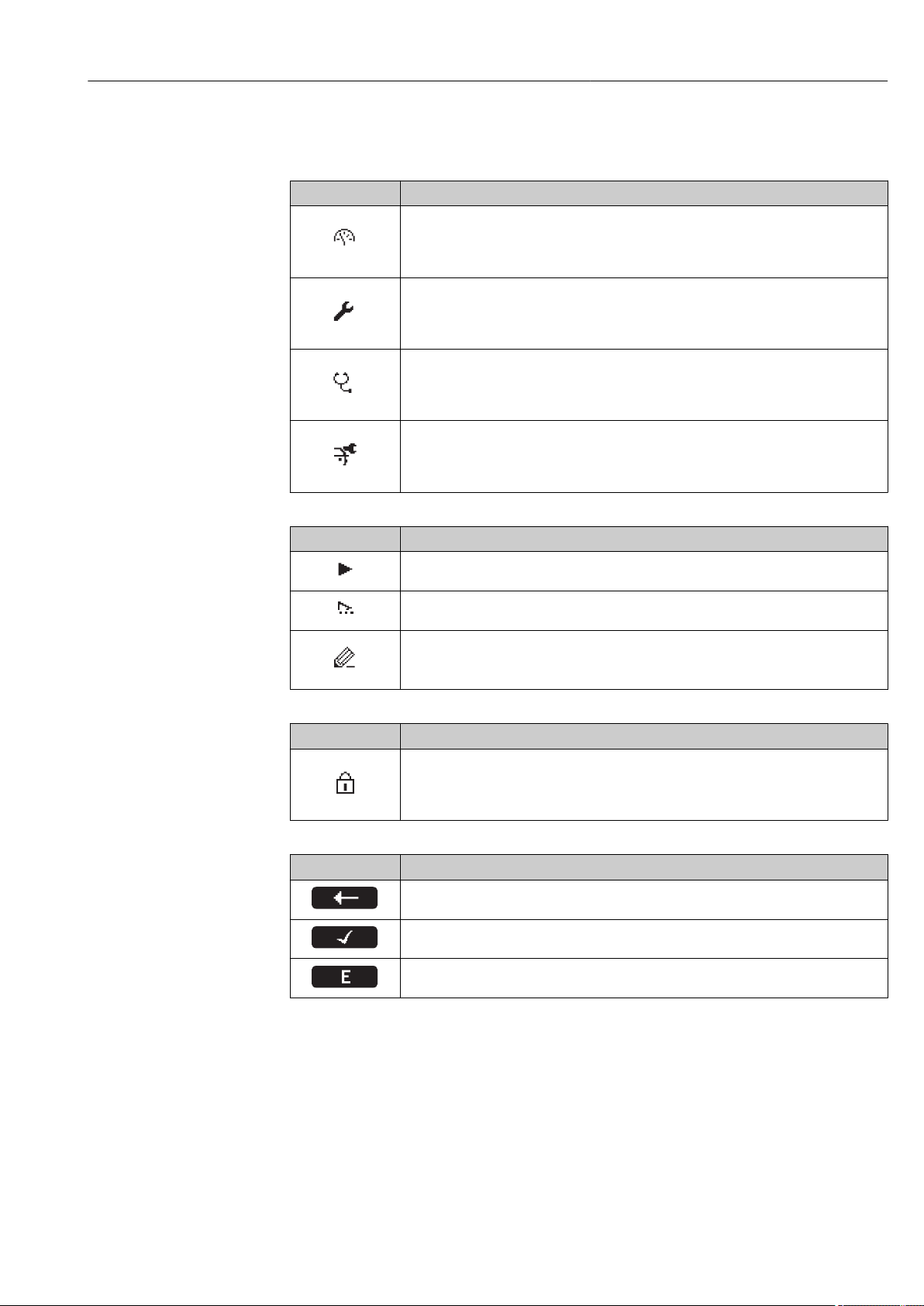
Proline Promass F 500 Modbus RS485 Operation options
Display area
Menus
Symbol Meaning
Operation
Appears:
• In the menu next to the "Operation" selection
• At the left in the navigation path in the Operation menu
Setup
Appears:
• In the menu next to the "Setup" selection
• At the left in the navigation path in the Setup menu
Diagnostics
Appears:
• In the menu next to the "Diagnostics" selection
• At the left in the navigation path in the Diagnostics menu
Expert
Appears:
• In the menu next to the "Expert" selection
• At the left in the navigation path in the Expert menu
Submenus, wizards, parameters
Symbol Meaning
Submenu
Wizard
Parameters within a wizard
Locking
Symbol Meaning
Parameter locked
When displayed in front of a parameter name, indicates that the parameter is locked.
• By a user-specific access code
• By the hardware write protection switch
Wizard operation
Symbol Meaning
Switches to the previous parameter.
Confirms the parameter value and switches to the next parameter.
Opens the editing view of the parameter.
No display symbol exists for parameters in submenus.
Endress+Hauser 69
Page 70
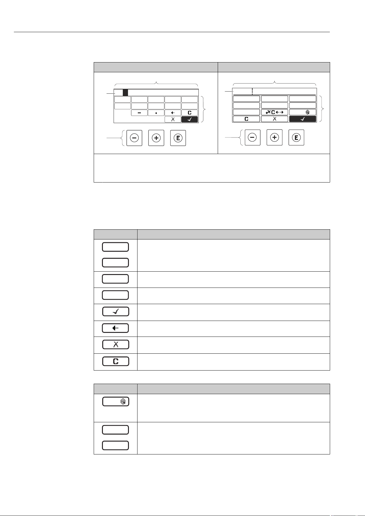
Operation options Proline Promass F 500 Modbus RS485
3
2
1
4
3
4
0
1 2
9
5
6
8
7
20
ABC_
DEFG
User
HIJK
LMNO
PQRS
TUVW
XYZ
Aa1
3
2
1
4
…
0
9
.
–
Aa1
XYZ
ABC
_
…
8.3.3 Editing view
Numeric editor Text editor
A0013999
1
Editing view
2
Display area of the entered values
3
Input mask
4
Operating elements → 71
A0013941
Input mask
The following input symbols are available in the input mask of the numeric and text editor:
Numeric editor
Symbol Meaning
Selection of numbers from 0 to 9.
Inserts decimal separator at the input position.
Inserts minus sign at the input position.
Confirms selection.
Moves the input position one position to the left.
Exits the input without applying the changes.
Clears all entered characters.
Text editor
Symbol Meaning
Toggle
• Between upper-case and lower-case letters
• For entering numbers
• For entering special characters
Selection of letters from A to Z.
70 Endress+Hauser
Page 71
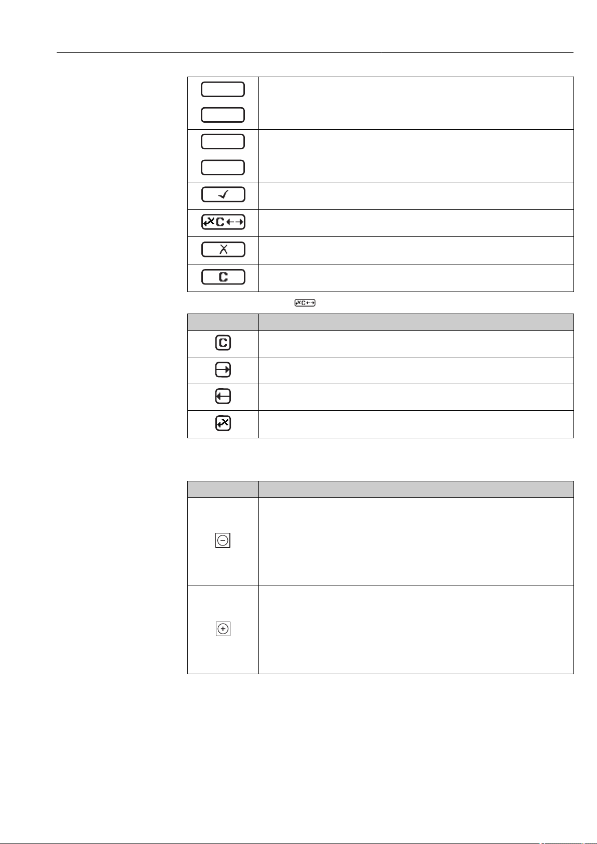
Proline Promass F 500 Modbus RS485 Operation options
xyz
abc
_
…
~&
"'^
_
…
_
Selection of letters from a to z.
Selection of special characters.
Confirms selection.
Switches to the selection of the correction tools.
Exits the input without applying the changes.
Clears all entered characters.
Correction symbols under
Symbol Meaning
Clears all entered characters.
Moves the input position one position to the right.
Moves the input position one position to the left.
Deletes one character immediately to the left of the input position.
8.3.4 Operating elements
Key Meaning
Minus key
In a menu, submenu
Moves the selection bar upwards in a choose list.
With a Wizard
Confirms the parameter value and goes to the previous parameter.
With a text and numeric editor
In the input mask, moves the selection bar to the left (backwards).
Plus key
In a menu, submenu
Moves the selection bar downwards in a choose list.
With a Wizard
Confirms the parameter value and goes to the next parameter.
With a text and numeric editor
Moves the selection bar to the right (forwards) in an input screen.
Endress+Hauser 71
Page 72
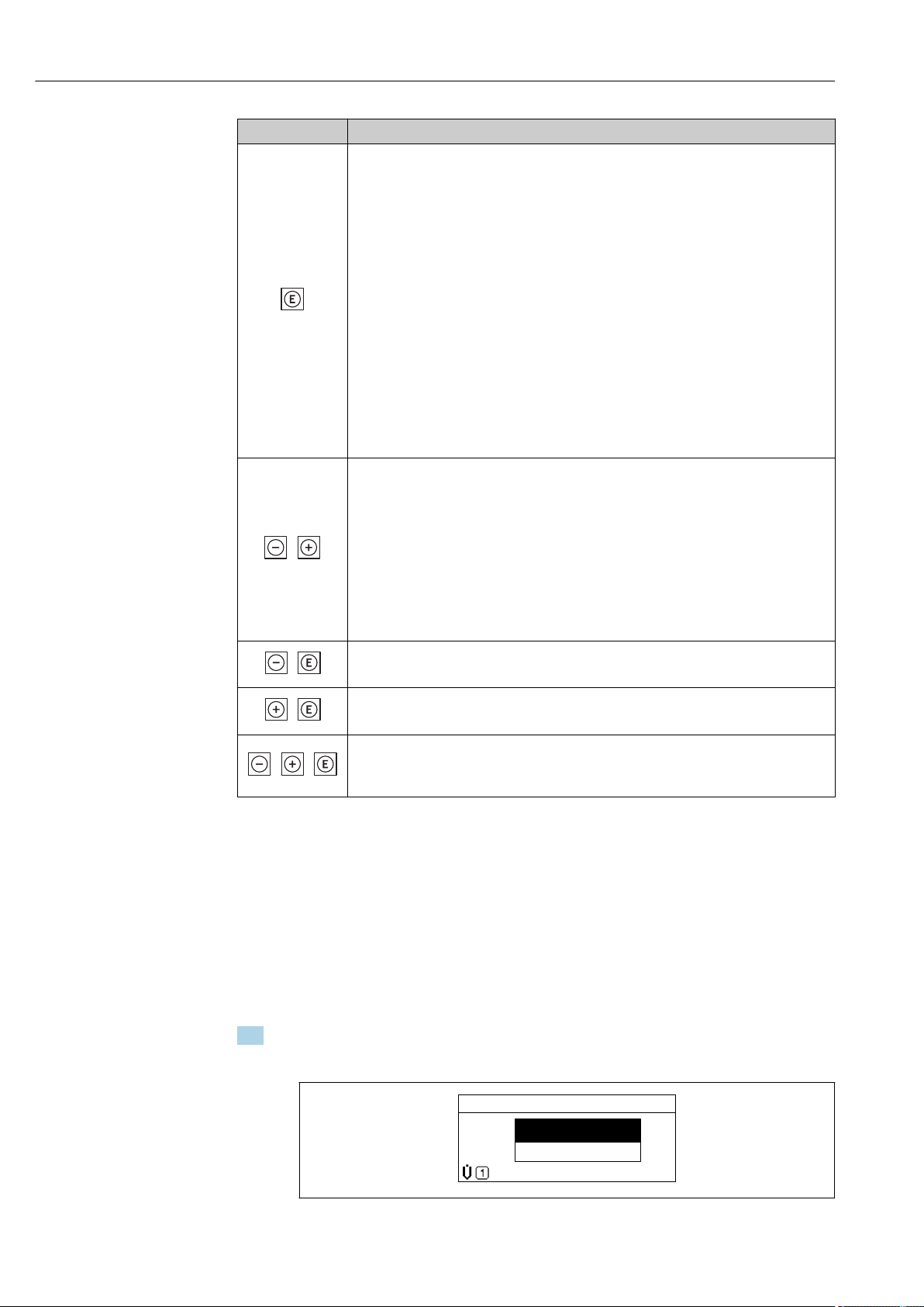
Operation options Proline Promass F 500 Modbus RS485
+
+
+
++
XXXXXXXXXX
l/h
20.50
Setup
Simulation
Key Meaning
Enter key
For operational display
• Pressing the key briefly opens the operating menu.
• Pressing the key for 2 s opens the context menu.
In a menu, submenu
• Pressing the key briefly:
– Opens the selected menu, submenu or parameter.
– Starts the wizard.
– If help text is open, closes the help text of the parameter.
• Pressing the key for 2 s for parameter:
If present, opens the help text for the function of the parameter.
With a Wizard
Opens the editing view of the parameter.
With a text and numeric editor
• Pressing the key briefly:
– Opens the selected group.
– Carries out the selected action.
• Pressing the key for 2 s confirms the edited parameter value.
Escape key combination (press keys simultaneously)
In a menu, submenu
• Pressing the key briefly:
– Exits the current menu level and takes you to the next higher level.
– If help text is open, closes the help text of the parameter.
• Pressing the key for 2 s returns you to the operational display ("home position").
With a Wizard
Exits the wizard and takes you to the next higher level.
With a text and numeric editor
Closes the text or numeric editor without applying changes.
Minus/Enter key combination (press the keys simultaneously)
Reduces the contrast (brighter setting).
Plus/Enter key combination (press and hold down the keys simultaneously)
Increases the contrast (darker setting).
Minus/Plus/Enter key combination (press the keys simultaneously)
For operational display
Enables or disables the keypad lock (only SD02 display module).
8.3.5 Opening the context menu
Using the context menu, the user can call up the following menus quickly and directly from
the operational display:
• Setup
• Data backup
• Simulation
Calling up and closing the context menu
The user is in the operational display.
1. Press for 2 s.
The context menu opens.
72 Endress+Hauser
A0017421-EN
Page 73

Proline Promass F 500 Modbus RS485 Operation options
2. Press + simultaneously.
The context menu is closed and the operational display appears.
Calling up the menu via the context menu
1. Open the context menu.
2. Press to navigate to the desired menu.
3. Press to confirm the selection.
The selected menu opens.
Endress+Hauser 73
Page 74
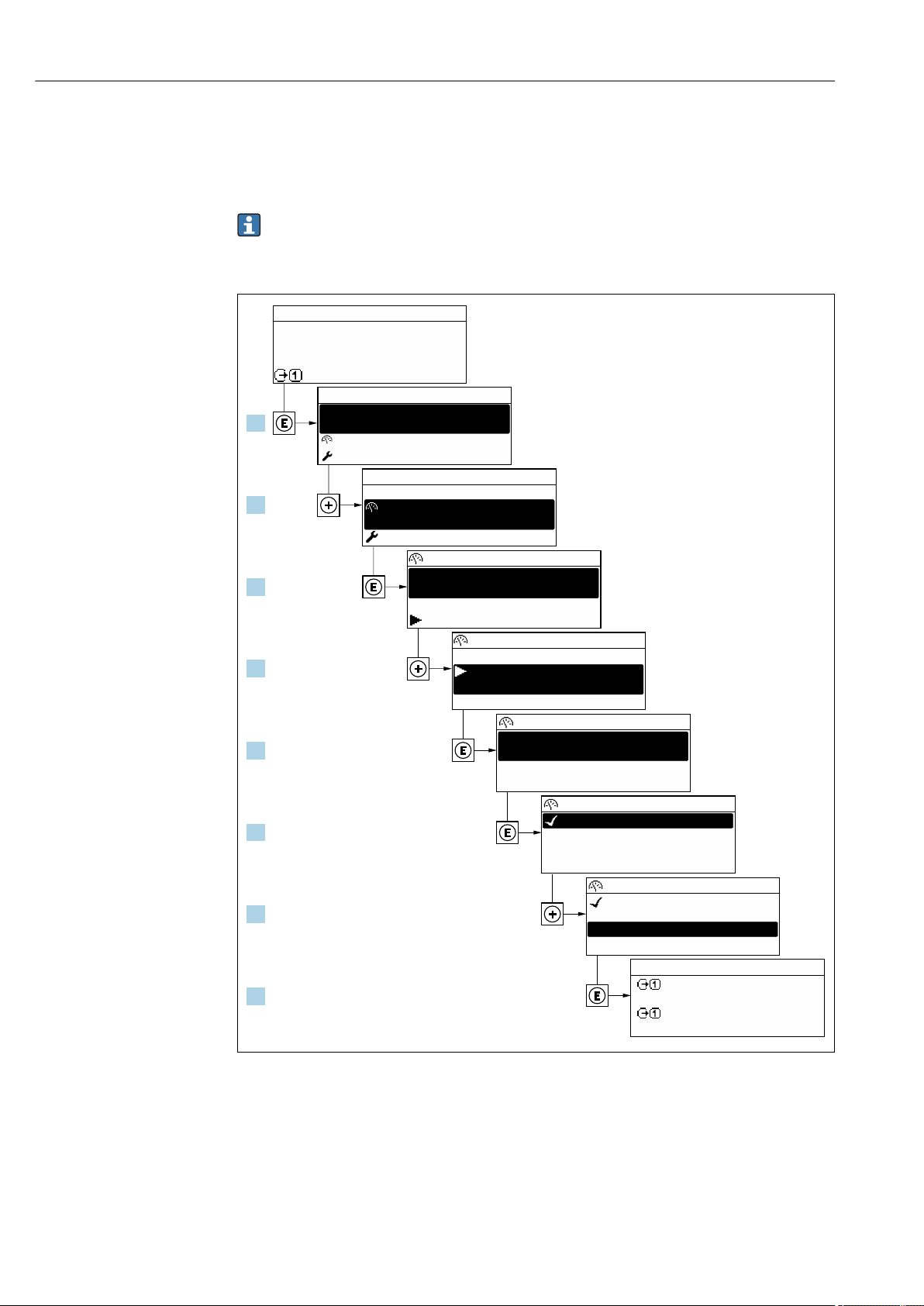
Operation options Proline Promass F 500 Modbus RS485
X X X X X X XX X
20.50
0104-1
2 s
0091-1
0098-1
0098-1
0098-1
X X X X X X XX X
10.50
2800
Hz
mA
3.
4.
5.
6.
7.
8.
1.
2.
Display/operat.
Display/operat.
Setup
Main menu
English
Main menu
Format display
/ ../Display
Contrast display
Display intervall
1 value, max.
Setup
Access stat.disp
/ ../Display/operat.
Display
Locking status
1 value, max.
/ ../Format display
2 values
Val. large+2val.
Bargr. + 1 value
Locking status
/ ../Display/operat.
Display
1 value, max.
/ ../Format display
2 values
Val. large+2val.
Bargr. + 1 value
Operator
Language
Language
8.3.6 Navigating and selecting from list
Different operating elements are used to navigate through the operating menu. The
navigation path is displayed on the left in the header. Icons are displayed in front of the
individual menus. These icons are also shown in the header during navigation.
For an explanation of the navigation view with symbols and operating elements
→ 68
Example: Setting the number of displayed measured values to "2 values"
74 Endress+Hauser
8.3.7 Calling the parameter directly
A parameter number is assigned to every parameter to be able to access a parameter
directly via the onsite display. Entering this access code in the Direct access parameter
calls up the desired parameter directly.
Navigation path
Expert → Direct access
A0029562-EN
Page 75
Proline Promass F 500 Modbus RS485 Operation options
1
0914-2
Ent.accesscode
Enteraccesscodetodisable
writeprotec.
The direct access code consists of a 4-digit number and the channel number, which
identifies the channel of a process variable: e.g. 0914-1. In the navigation view, this
appears on the right-hand side in the header of the selected parameter.
A0029414
1 Direct access code
Note the following when entering the direct access code:
• The leading zeros in the direct access code do not have to be entered.
Example: Input of "914" instead of "0914"
• If no channel number is entered, channel 1 is jumped to automatically.
Example: Enter 0914 → Assign process variable parameter
• If a different channel is jumped to: Enter the direct access code with the corresponding
channel number.
Example: Enter 0914-2 → Assign process variable parameter
For the direct access codes of the individual parameters, see the "Description of Device
Parameters" document for the device
8.3.8 Calling up help text
Help text is available for some parameters and can be called up from the navigation view.
The help text provides a brief explanation of the parameter function and thereby supports
swift and safe commissioning.
Calling up and closing the help text
The user is in the navigation view and the selection bar is on a parameter.
1. Press for 2 s.
The help text for the selected parameter opens.
A0014002-EN
28 Example: Help text for parameter "Enter access code"
2. Press + simultaneously.
The help text is closed.
Endress+Hauser 75
Page 76
Operation options Proline Promass F 500 Modbus RS485
3x
001-FT-101
DEFG HIJK
LMNO
PQRS TUVW
XYZ
Aa1@
ABC
001-FT-101
DEFG HIJK
LMNO
PQRS TUVW
XYZ
Aa1@
ABC
001-FT-101
DEFG HIJK
ABC
001-FT-10
DEFG HIJK
ABC
001-FT-10
DEFG HIJK
ABC
1x
001-FT-10
DEFG HIJK
LMNO
PQRS TUVW
XYZ
Aa1@
ABC
001-FT-10
DEFG HIJK
LMNO
PQRS TUVW
XYZ
Aa1@
ABC
001-FT-10
DEFG HIJK
ABC
A a 1
@
001-FT-10
DEFG HIJK
ABC
A a 1
@
001-FT-10
3456 789
= + - *
/
[ ]
( )
< >
{ }
Aa1@
012
001-FT-10
3456 789
012
0 1 2
001-FT-10
3456 789
012
0 1 2
001-FT-102
3456 789
012
0 1 2
001-FT-102
3456 789
= + - *
/
[ ]
( )
< >
{ }
Aa1@
012
001-FT-102
3456 789
012
0 1 2
001-FT-102
3456 789
= + - *
/
[ ]
( )
< >
{ }
Aa1@
012
001-FT-102
3456 789
012
0 1 2
001-FT-102
3456 789
= + - *
/
[ ]
( )
< >
{ }
Aa1@
012
001-FT-102
1496-1
1x
2x
4x
2x
1x
001-FT-101
1496-1
1.
2.
3.
4.
5.
6.
7.
8.
9.
Max.
Tag description
Ent. access code
Def. access code
/../Advanced setup
Tag description
/../Advanced setup
Ent. access code
Def. access code
8.3.9 Changing the parameters
For a description of the editing display - consisting of text editor and numeric editor with symbols → 70, for a description of the operating elements → 71
Example: Changing the tag name in the "Tag description" parameter from 001-FT-101 to
001-FT-102
76 Endress+Hauser
A message is displayed if the value entered is outside the permitted value range.
A0029563-EN
Page 77
Proline Promass F 500 Modbus RS485 Operation options
Ent.accesscode
Invalidoroutofrangeinput
value
Max:9999
Min:0
A0014049-EN
8.3.10 User roles and related access authorization
The two user roles "Operator" and "Maintenance" have different write access to the
parameters if the customer defines a user-specific access code. This protects the device
configuration via the local display from unauthorized access → 137.
Access authorization to parameters: "Operator" user role
Access code status Read access Write access
An access code has not yet been defined
(factory setting).
After an access code has been defined. ––
1)
1) Despite the defined access code, certain parameters can always be modified and thus are excepted from
the write protection, as they do not affect the measurement. Refer to the "Write protection via access code"
section
Access authorization to parameters: "Maintenance" user role
Access code status Read access Write access
An access code has not yet been defined
(factory setting).
After an access code has been defined.
1) If an incorrect access code is entered, the user obtains the access rights of the "Operator" user role.
1)
The user role with which the user is currently logged on is indicated by the Access
status parameter. Navigation path: Operation → Access status
8.3.11 Disabling write protection via access code
If the -symbol appears on the local display in front of a parameter, the parameter is
write-protected by a user-specific access code and its value cannot be changed at the
moment using local operation → 137.
Parameter write protection via local operation can be disabled by entering the user-specific
access code in the Enter access code parameter via the respective access option.
1. After you press , the input prompt for the access code appears.
2. Enter the access code.
The -symbol in front of the parameters disappears; all previously write-
protected parameters are now re-enabled.
Endress+Hauser 77
8.3.12 Enabling and disabling the keypad lock
The keypad lock makes it possible to block access to the entire operating menu via local
operation. As a result, it is no longer possible to navigate through the operating menu or
change the values of individual parameters. Users can only read the measured values on
the operational display.
Page 78
Operation options Proline Promass F 500 Modbus RS485
Local operation with touch control
The keypad lock is switched on and off via the context menu.
Switching on the keypad lock
The keypad lock is switched on automatically:
• Each time the device is restarted.
• If the device has not been operated for longer than one minute in the measured value
display.
1. The device is in the measured value display.
Press for at least 2 seconds.
A context menu appears.
2. In the context menu, select the Keylock on option.
The keypad lock is switched on.
If the user attempts to access the operating menu while the keypad lock is active, the
message Keylock on appears.
Switching off the keypad lock
1. The keypad lock is switched on.
Press for at least 2 seconds.
A context menu appears.
2. In the context menu, select the Keylock off option.
The keypad lock is switched off.
8.4 Access to the operating menu via the Web browser
8.4.1 Function range
Thanks to the integrated Web server, the device can be operated and configured via a Web
browser and via a service interface (CDI-RJ45) or a WLAN interface. The structure of the
operating menu is the same as for the local display. In addition to the measured values,
status information on the device is also displayed and allows the user to monitor the status
of the device. Furthermore the measuring device data can be managed and the network
parameters can be configured. The WLAN connection requires a device that acts as an
access point to enable communication via a computer or mobile handheld terminal.
For additional information on the Web server, refer to the Special Documentation for
the device → 211
8.4.2 Prerequisites
Computer hardware
Hardware Interface
CDI-RJ45 WLAN
Interface The computer must have an RJ45
interface.
Connection Standard Ethernet cable with RJ45
connector.
Screen Recommended size: ≥12" (depends on the screen resolution)
The operating unit must have a
WLAN interface.
Connection via Wireless LAN.
78 Endress+Hauser
Page 79
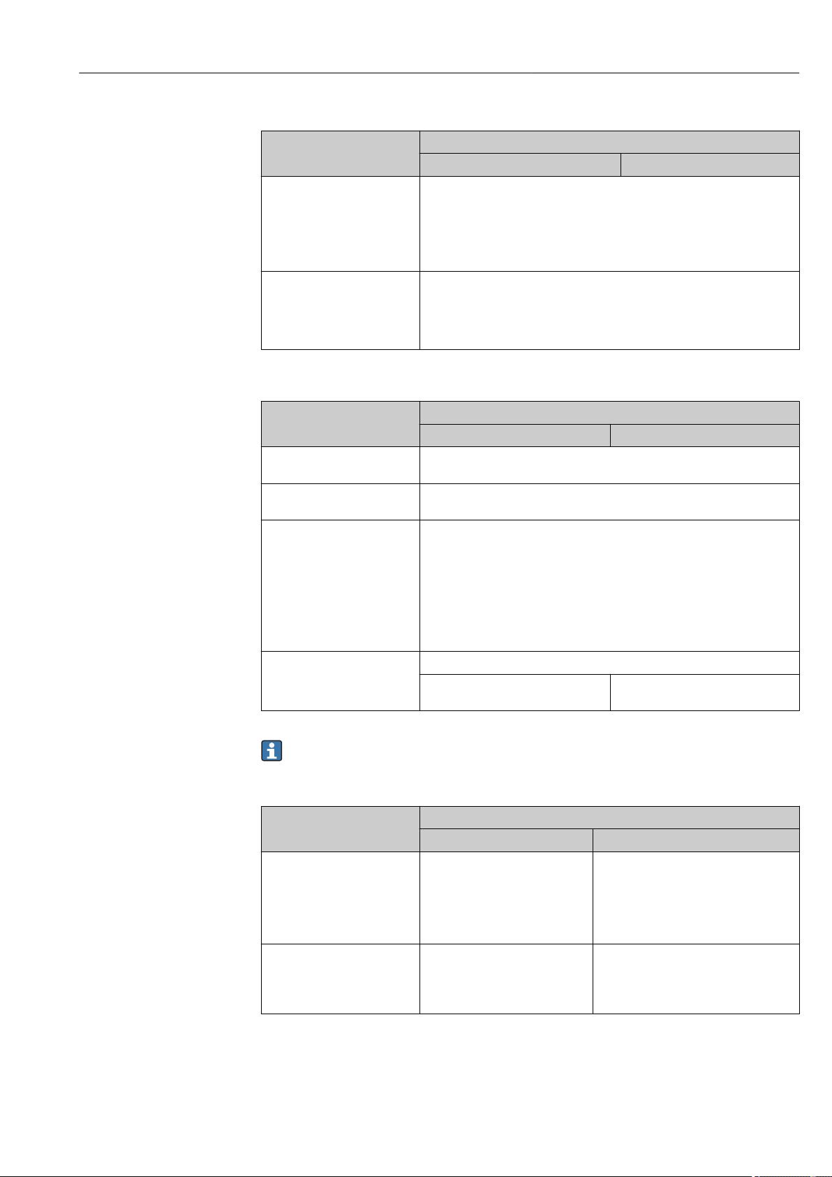
Proline Promass F 500 Modbus RS485 Operation options
Computer software
Software Interface
CDI-RJ45 WLAN
Recommended operating
systems
Web browsers supported • Microsoft Internet Explorer 8 or higher
• Microsoft Windows 7 or higher.
• Mobile operating systems:
– iOS
– Android
Microsoft Windows XP is supported.
• Microsoft Edge
• Mozilla Firefox
• Google Chrome
• Safari
Computer settings
Settings Interface
CDI-RJ45 WLAN
User rights Appropriate user rights (e.g. administrator rights) for TCP/IP and proxy server
settings are necessary (for adjusting the IP address, subnet mask etc.).
Proxy server settings of the
Web browser
JavaScript JavaScript must be enabled.
Network connections Only the active network connections to the measuring device should be used.
The Web browser setting Use a Proxy Server for Your LAN must be
deselected .
If JavaScript cannot be enabled:
enter http://192.168.1.212/basic.html in the address line of the Web
browser. A fully functional but simplified version of the operating menu
structure starts in the Web browser.
When installing a new firmware version: To enable correct data display,
clear the temporary memory (cache) of the Web browser under Internet
options.
Switch off all other network
connections such as WLAN.
Switch off all other network
connections.
In the event of connection problems: → 153
Measuring device
Device Interface
CDI-RJ45 WLAN
Measuring device The measuring device has an RJ45
interface.
Web server Web server must be enabled;
factory setting: ON
For information on enabling
the Web server → 83
The measuring device has a WLAN
antenna:
• Transmitter with integrated WLAN
antenna
• Transmitter with external WLAN
antenna
Web server and WLAN must be enabled;
factory setting: ON
For information on enabling the
Web server → 83
Endress+Hauser 79
Page 80
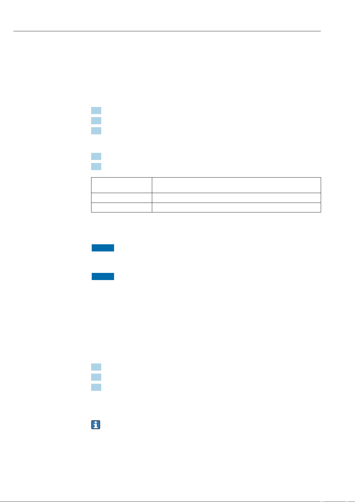
Operation options Proline Promass F 500 Modbus RS485
8.4.3 Establishing a connection
Via service interface (CDI-RJ45)
Configuring the Internet protocol of the computer
The following information refers to the default Ethernet settings of the device.
IP address of the device: 192.168.1.212 (factory setting)
1. Switch on the measuring device.
2. Connect to the computer using a cable → 84.
3. If a 2nd network card is not used, close all the applications on the notebook.
Applications requiring Internet or a network, such as e-mail, SAP applications,
Internet or Windows Explorer.
4. Close any open Internet browsers.
5. Configure the properties of the Internet protocol (TCP/IP) as defined in the table:
IP address 192.168.1.XXX; for XXX all numerical sequences except: 0, 212 and 255 → e.g.
192.168.1.213
Subnet mask 255.255.255.0
Default gateway 192.168.1.212 or leave cells empty
Via WLAN interface
Configuring the Internet protocol of the operating unit
NOTICE
If the WLAN connection is lost during the configuration, settings made may be lost.
Make sure that the WLAN connection is not disconnected while configuring the device.
‣
NOTICE
In principle, avoid simultaneous access to the measuring device via the service
interface (CDI-RJ45) and the WLAN interface from the same operating unit. This
could cause a network conflict.
Only activate one service interface (CDI-RJ45 service interface or WLAN interface).
‣
If simultaneous communication is necessary: configure different IP address ranges, e.g.
‣
192.168.0.1 (WLAN interface) and 192.168.1.212 (CDI-RJ45 service interface).
Preparation
Enable WLAN reception on the operating unit.
‣
Establishing a connection
1. Select the measuring device using the SSID (e.g. EH_Promass_500_A802000).
2. If necessary, select the WPA2 encryption method.
3. Enter the password: serial number of the measuring device ex-works (e.g.
L100A802000).
LED on display module flashes: it is now possible to operate the measuring device
with the Web browser, FieldCare or DeviceCare.
The serial number can be found on the nameplate.
Disconnecting
Once the configuration is completed, disconnect the WLAN connection between the
‣
operating unit and the measuring device.
80 Endress+Hauser
Page 81
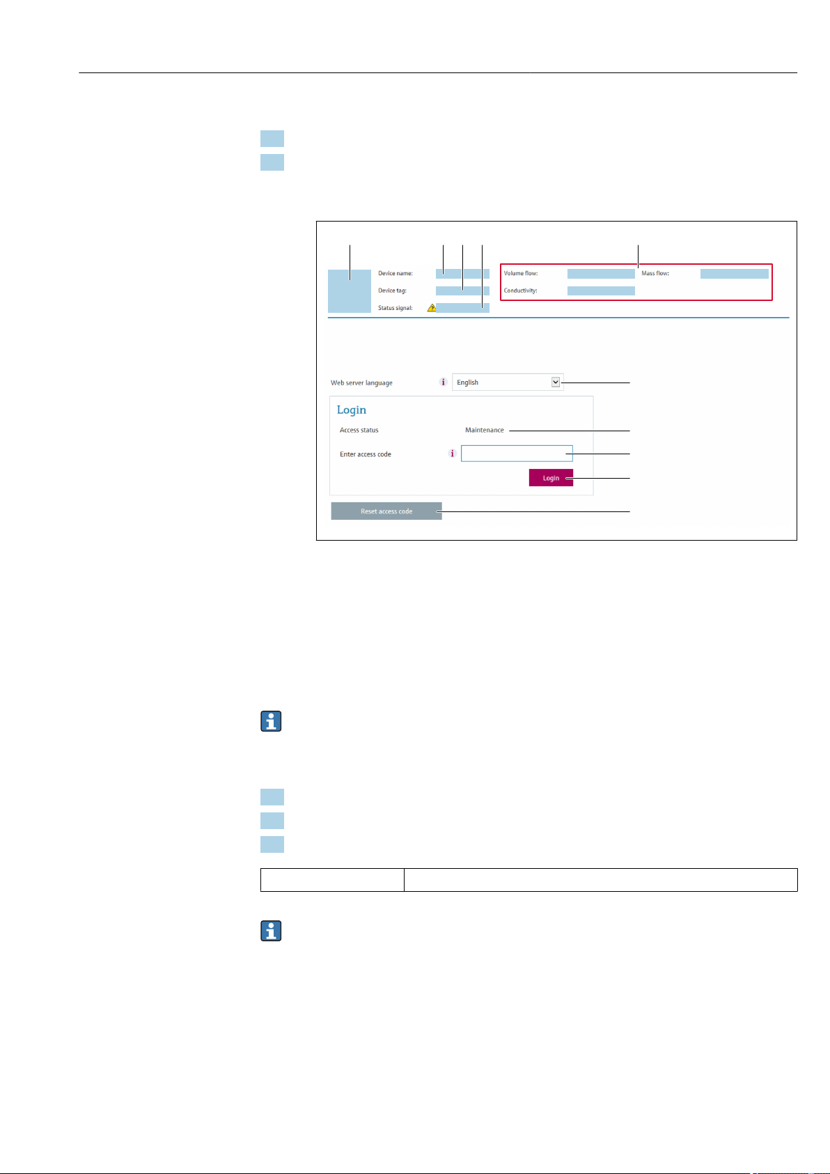
Proline Promass F 500 Modbus RS485 Operation options
6
7
8
9
10
1 52 3 4
Starting the Web browser
1. Start the Web browser on the computer.
2. Enter the IP address of the Web server in the address line of the Web browser:
192.168.1.212
The login page appears.
A0029417
1 Picture of device
2 Device name
3 Device tag
4 Status signal
5 Current measured values
6 Operating language
7 User role
8 Access code
9 Login
10 Reset access code (→ 134)
If a login page does not appear, or if the page is incomplete → 153
8.4.4 Logging on
1. Select the preferred operating language for the Web browser.
2. Enter the user-specific access code.
3. Press OK to confirm your entry.
Access code 0000 (factory setting); can be changed by customer
If no action is performed for 10 minutes, the Web browser automatically returns to
the login page.
Endress+Hauser 81
Page 82
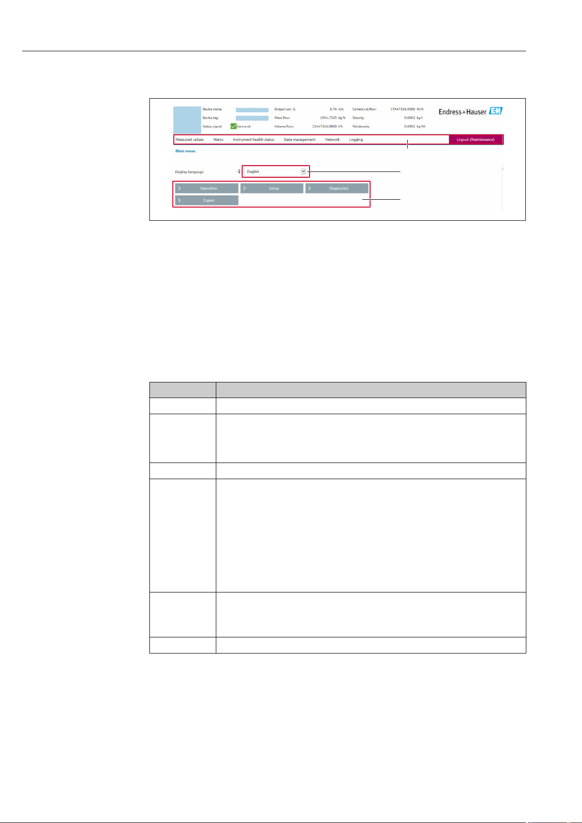
Operation options Proline Promass F 500 Modbus RS485
2
1
3
8.4.5 User interface
A0029418
1 Function row
2 Operating language
3 Navigation area
Header
The following information appears in the header:
• Device tag
• Device status with status signal → 161
• Current measured values
Function row
Functions Meaning
Measured values Displays the measured values of the measuring device
• Access to the operating menu from the measuring device
Menu
Device status Displays the diagnostic messages currently pending, listed in order of priority
Data
management
Network
configuration
Logout End the operation and call up the login page
• The structure of the operating menu is the same as for the local display
For detailed information on the structure of the operating menu, see the Operating
Instructions for the measuring device
• Data exchange between PC and measuring device:
– Load the configuration from the measuring device
(XML format, save configuration)
– Save the configuration to the measuring device
(XML format, restore configuration)
– Export the event list (.csv file)
– Export parameter settings
(.csv file, create documentation of the measuring point configuration)
– Export the Heartbeat verification log
(PDF file, only available with the "Heartbeat Verification" application package)
• Flashing a firmware version
Configuration and checking of all the parameters required for establishing the connection
to the measuring device:
• Network settings (e.g. IP address, MAC address)
• Device information (e.g. serial number, firmware version)
Navigation area
If a function is selected in the function bar, the submenus of the function open in the
navigation area. The user can now navigate through the menu structure.
82 Endress+Hauser
Page 83
Proline Promass F 500 Modbus RS485 Operation options
Working area
Depending on the selected function and the related submenus, various actions can be
performed in this area:
• Configuring parameters
• Reading measured values
• Calling up help text
• Starting an upload/download
8.4.6 Disabling the Web server
The Web server of the measuring device can be switched on and off as required using the
Web server functionality parameter.
Navigation
"Expert" menu → Communication → Web server
Parameter overview with brief description
Parameter Description Selection Factory setting
Web server functionality Switch the Web server on and off. • Off
• On
On
Function scope of the "Web server functionality" parameter
Option Description
Off • The web server is completely disabled.
• Port 80 is locked.
On • The complete functionality of the web server is available.
• JavaScript is used.
• The password is transferred in an encrypted state.
• Any change to the password is also transferred in an encrypted state.
Enabling the Web server
If the Web server is disabled it can only be re-enabled with the Web server functionality
parameter via the following operating options:
• Via local display
• Via Bedientool "FieldCare"
• Via "DeviceCare" operating tool
8.4.7 Logging out
Before logging out, perform a data backup via the Data management function
(upload configuration from device) if necessary.
1. Select the Logout entry in the function row.
The home page with the Login box appears.
2. Close the Web browser.
3. Reset the modified properties of the Internet protocol (TCP/IP) if they are no longer
needed → 80.
8.5 Access to the operating menu via the operating tool
The structure of the operating menu in the operating tools is the same as for operation via
the local display.
Endress+Hauser 83
Page 84
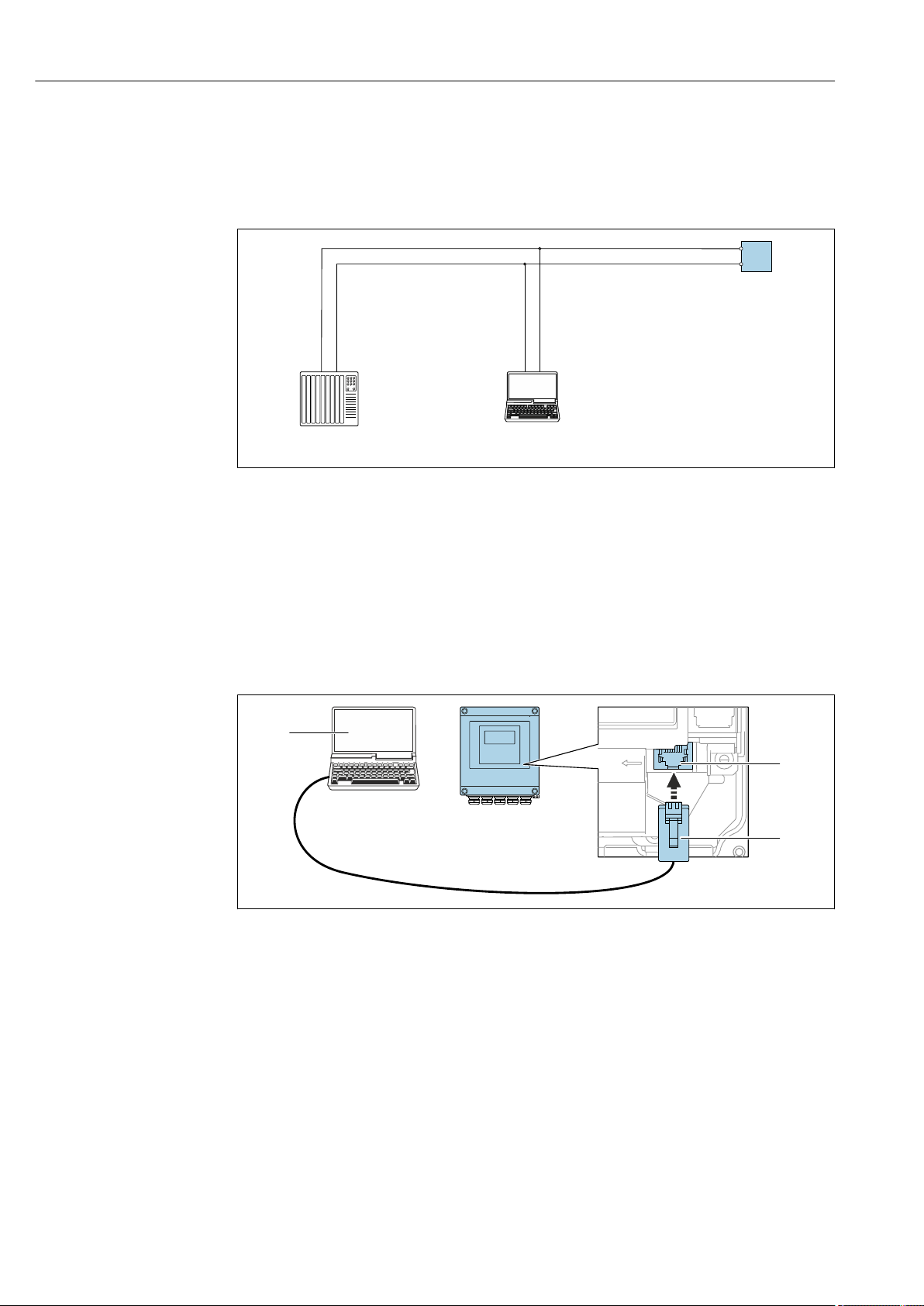
Operation options Proline Promass F 500 Modbus RS485
1 2
3
open
press
2
3
8.5.1 Connecting the operating tool
Via Modbus RS485 protocol
This communication interface is available in device versions with a Modbus-RS485 output.
A0029437
29 Options for remote operation via Modbus-RS485 protocol (active)
1 Control system (e.g. PLC)
2 Computer with Web browser (e.g. Internet Explorer) for accessing the integrated device Web server or with
operating tool (e.g. FieldCare, DeviceCare) with COM DTM "CDI Communication TCP/IP" or Modbus DTM
3 Transmitter
Service interface
Via service interface (CDI-RJ45)
Proline 500 – digital transmitter
A0029163
30 Connection via service interface (CDI-RJ45)
1 Computer with Web browser (e.g. Microsoft Internet Explorer, Microsoft Edge) for accessing the integrated
device Web server or with "FieldCare", "DeviceCare" operating tool with COM DTM "CDI Communication TCP/IP"
or Modbus DTM
2 Standard Ethernet connecting cable with RJ45 connector
3 Service interface (CDI-RJ45) of the measuring device with access to the integrated Web server
84 Endress+Hauser
Page 85
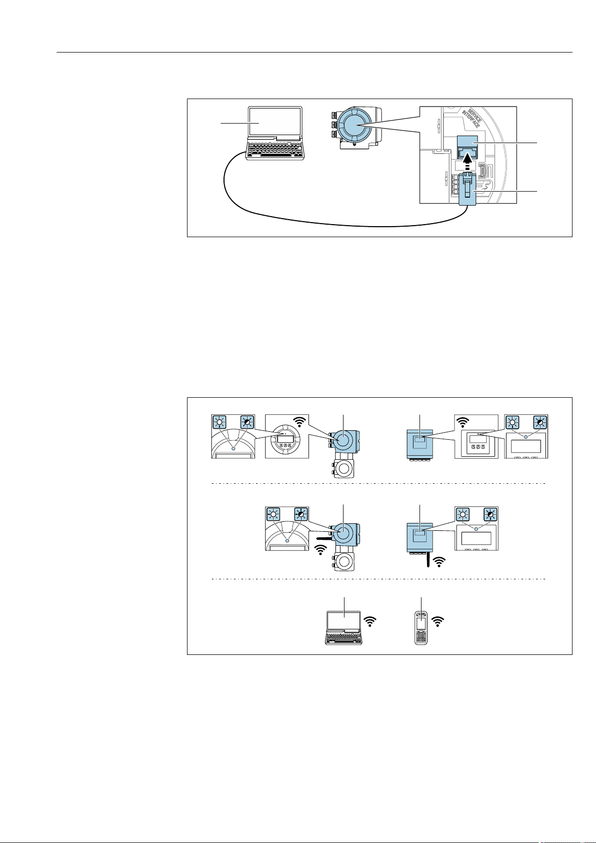
Proline Promass F 500 Modbus RS485 Operation options
2
3
5
6
1
2 2
1
3
4
3
4
3
4
3
4
Proline 500 transmitter
A0027563
31 Connection via service interface (CDI-RJ45)
1 Computer with Web browser (e.g. Microsoft Internet Explorer, Microsoft Edge) for accessing the integrated
device Web server or with "FieldCare", "DeviceCare" operating tool with COM DTM "CDI Communication TCP/IP"
or Modbus DTM
2 Standard Ethernet connecting cable with RJ45 connector
3 Service interface (CDI-RJ45) of the measuring device with access to the integrated Web server
Via WLAN interface
The optional WLAN interface is available on the following device version:
Order code for "Display; operation", option G "4-line, backlit, graphic display; touch control +
WLAN"
A0029165
1 Transmitter with integrated WLAN antenna
2 Transmitter with external WLAN antenna
3 LED lit constantly: WLAN reception is enabled on measuring device
4 LED flashing: WLAN connection established between operating unit and measuring device
5 Computer with WLAN interface and Web browser (e.g. Microsoft Internet Explorer, Microsoft Edge) for
accessing the integrated device Web server or with operating tool (e.g. FieldCare, DeviceCare)
6 Mobile handheld terminal with WLAN interface and Web browser (e.g. Microsoft Internet Explorer, Microsoft
Edge) for accessing the integrated device Web server or operating tool (e.g. FieldCare, DeviceCare)
Endress+Hauser 85
Page 86

Operation options Proline Promass F 500 Modbus RS485
Wireless LAN IEEE 802.11 b/g (2.4 GHz) WLAN
Encryption WPA2 PSK/TKIP AES-128
Configurable channels 1 to 11
Function Access point with DHCP
Range with integrated
antenna
Range with external
antenna
Max. 10 m (32 ft)
Max. 50 m (164 ft)
Configuring the Internet protocol of the operating unit
NOTICE
If the WLAN connection is lost during the configuration, settings made may be lost.
Make sure that the WLAN connection is not disconnected while configuring the device.
‣
NOTICE
In principle, avoid simultaneous access to the measuring device via the service
interface (CDI-RJ45) and the WLAN interface from the same operating unit. This
could cause a network conflict.
Only activate one service interface (CDI-RJ45 service interface or WLAN interface).
‣
If simultaneous communication is necessary: configure different IP address ranges, e.g.
‣
192.168.0.1 (WLAN interface) and 192.168.1.212 (CDI-RJ45 service interface).
Preparation
Enable WLAN reception on the operating unit.
‣
Establishing a connection
1. Select the measuring device using the SSID (e.g. EH_Promass_500_A802000).
2. If necessary, select the WPA2 encryption method.
3. Enter the password: serial number of the measuring device ex-works (e.g.
L100A802000).
LED on display module flashes: it is now possible to operate the measuring device
with the Web browser, FieldCare or DeviceCare.
The serial number can be found on the nameplate.
Disconnecting
Once the configuration is completed, disconnect the WLAN connection between the
‣
operating unit and the measuring device.
8.5.2 FieldCare
Function scope
FDT-based plant asset management tool from Endress+Hauser. It can configure all smart
field devices in a system and helps you manage them. By using the status information, it is
also a simple but effective way of checking their status and condition.
Access is via:
• CDI-RJ45 service interface → 84
• WLAN interface→ 85
86 Endress+Hauser
Page 87
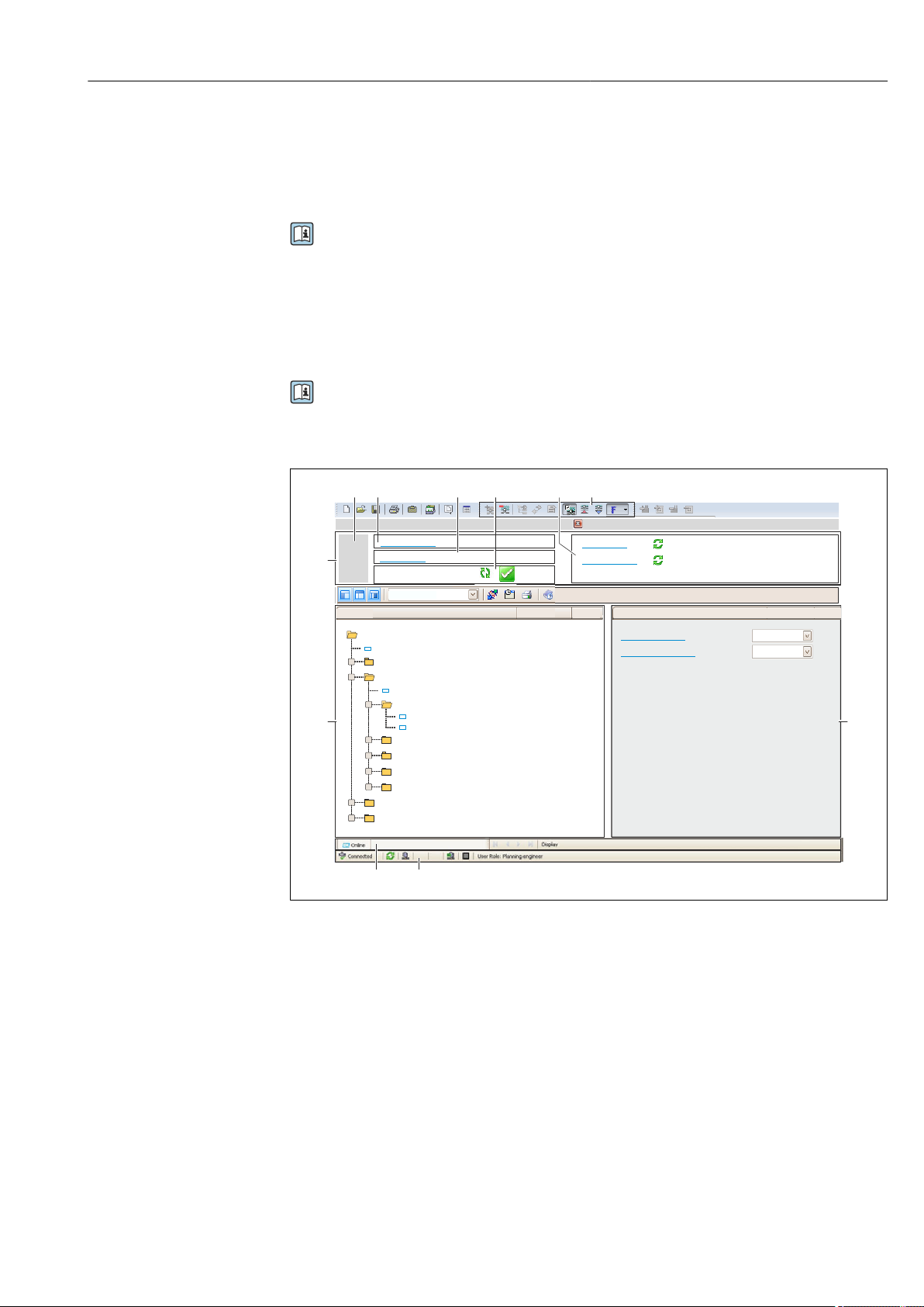
Proline Promass F 500 Modbus RS485 Operation options
6
5
32
1
Xxxxxx/…/…/
7
P
P
+
–
P
–
P
+
+
+
+
+
+
4
8 9
10
11
Xxxxxxx
GoodStatus:
Device tag:
Xxxxxxx
Device name:
Mass flow:
12.34
kg/h
Volume flow:
12.34
m /h³
Mass flow unit:
Volume flow unit:
kg/h
m /h³
Access status tooling
Operation
Setup
Xxxxxx
Mass flow unit
Volume flow unit
Select medium
Device tag
…
…
Advanced setup
Diagnostics
Expert
Maintenance
kg/h
m /h³
Xxxxxx
System units
Typical functions:
• Configuring parameters of transmitters
• Loading and saving device data (upload/download)
• Documentation of the measuring point
• Visualization of the measured value memory (line recorder) and event logbook
For additional information about FieldCare, see Operating Instructions BA00027S
and BA00059S
Source for device description files
See information → 89
Establishing a connection
For additional information, see Operating Instructions BA00027S and BA00059S
User interface
1 Header
2 Picture of device
3 Device name
4 Tag name
5 Status area with status signal→ 161
6 Display area for current measured values
7 Edit toolbar with additional functions such as save/restore, event list and create documentation
8 Navigation area with operating menu structure
9 Working area
10 Range of action
11 Status area
8.5.3 DeviceCare
Function scope
Tool to connect and configure Endress+Hauser field devices.
Endress+Hauser 87
A0021051-EN
Page 88

Operation options Proline Promass F 500 Modbus RS485
The fastest way to configure Endress+Hauser field devices is with the dedicated
"DeviceCare" tool. Together with the device type managers (DTMs) it presents a convenient,
comprehensive solution.
For details, see Innovation Brochure IN01047S
Source for device description files
See information → 89
88 Endress+Hauser
Page 89
Proline Promass F 500 Modbus RS485 System integration
9 System integration
9.1 Overview of device description files
9.1.1 Current version data for the device
Firmware version 01.00.zz • On the title page of the Operating instructions
• On the transmitter nameplate
• Firmware version
Diagnostics → Device information → Firmware
version
Release date of firmware version 08.2016 ---
For an overview of the different firmware versions for the device → 174
9.1.2 Operating tools
The suitable device description file for the individual operating tools is listed in the table
below, along with information on where the file can be acquired.
Operating tool via service
interface (CDI) or Modbus
interface
FieldCare • www.endress.com → Download Area
DeviceCare • www.endress.com → Download Area
Sources for obtaining device descriptions
• CD–ROM (contact Endress+Hauser)
• DVD (contact Endress+Hauser)
• CD–ROM (contact Endress+Hauser)
• DVD (contact Endress+Hauser)
9.2 Compatibility with earlier model
If the device is replaced, the measuring device Promass 500 supports the compatibility of
the Modbus registers for the process variables and the diagnostic information with
previous models Promass 83. It is not necessary to change the engineering parameters in
the automation system.
Compatible Modbus registers: process variables
Process variable Compatible Modbus registers
Mass flow 2007
Volume flow 2009
Corrected volume flow 2011
Density 2013
Reference density 2015
Temperature 2017
Totalizer 1 2610
Totalizer 2 2810
Totalizer 3 3010
Endress+Hauser 89
Page 90

System integration Proline Promass F 500 Modbus RS485
Compatible Modbus registers: diagnostic information
Diagnostic information Compatible Modbus registers
Diagnostic code (data type: String), e.g. F270 6821
Diagnostic number (data type: Integer), e.g. 270 6859
The Modbus registers are compatible but the diagnostic numbers are not. Overview of
the new diagnostic numbers → 164.
9.3 Modbus RS485 information
9.3.1 Function codes
Function codes are used to define which read or write action is carried out via the Modbus
protocol. The measuring device supports the following function codes:
Code Name Description Application
03 Read holding
register
04 Read input
register
06 Write single
registers
08 Diagnostics Master checks the communication
Master reads one or more Modbus
registers from the device.
A maximum of 125 consecutive
registers can be read with 1
telegram: 1 register = 2 bytes
The measuring device does
not make a distinction
between function codes 03
and 04; these codes therefore
yield the same result.
Master reads one or more Modbus
registers from the device.
A maximum of 125 consecutive
registers can be read with 1
telegram: 1 register = 2 bytes
The measuring device does
not make a distinction
between function codes 03
and 04; these codes therefore
yield the same result.
Master writes a new value to one
Modbus register of the measuring
device.
Use function code 16 to write
multiple registers with just 1
telegram.
connection to the measuring device.
The following "Diagnostics codes"
are supported:
• Sub-function 00 = Return query
data (loopback test)
• Sub-function 02 = Return
diagnostics register
Read device parameters with read
and write access
Example:
Read mass flow
Read device parameters with read
access
Example:
Read totalizer value
Write only 1 device parameter
Example: reset totalizer
90 Endress+Hauser
Page 91
Proline Promass F 500 Modbus RS485 System integration
Code Name Description Application
16 Write multiple
registers
23 Read/Write
multiple
registers
Master writes a new value to
multiple Modbus registers of the
device.
A maximum of 120 consecutive
registers can be written with 1
telegram.
If the required device
parameters are not available
as a group, yet must
nevertheless be addressed
with a single telegram, use
Modbus data map → 91
Master reads and writes a
maximum of 118 Modbus registers
of the measuring device
simultaneously with 1 telegram.
Write access is executed before
read access.
Write multiple device parameters
Example:
• Mass flow unit
• Mass unit
Write and read multiple device
parameters
Example:
• Read mass flow
• Reset totalizer
Broadcast messages are only allowed with function codes 06, 16 and 23.
9.3.2 Register information
For an overview of device parameters with their respective Modbus register
information, please refer to the "Modbus RS485 register information" section in the
"Description of device parameters" documentation → 210.
9.3.3 Response time
Response time of the measuring device to the request telegram of the Modbus master:
typically 3 to 5 ms
9.3.4 Modbus data map
Function of the Modbus data map
The device offers a special memory area, the Modbus data map (for a maximum of 16
device parameters), to allow users to call up multiple device parameters via Modbus RS485
and not only individual device parameters or a group of consecutive device parameters.
Grouping of device parameters is flexible and the Modbus master can read or write to the
entire data block simultaneously with a single request telegram.
Structure of the Modbus data map
The Modbus data map consists of two data sets:
• Scan list: Configuration area
The device parameters to be grouped are defined in a list in that their Modbus RS485
register addresses are entered in the list.
• Data area
The measuring device reads out the register addresses entered in the scan list cyclically
and writes the associated device data (values) to the data area.
For an overview of device parameters with their respective Modbus register
information, please refer to the "Modbus RS485 register information" section in the
"Description of device parameters" documentation → 210.
Endress+Hauser 91
Page 92
System integration Proline Promass F 500 Modbus RS485
Scan list configuration
For configuration, the Modbus RS485 register addresses of the device parameters to be
grouped must be entered in the scan list. Please note the following basic requirements of
the scan list:
Max. entries 16 device parameters
Supported device parameters Only parameters with the following characteristics are supported:
• Access type: read or write access
• Data type: float or integer
Configuring the scan list via FieldCare or DeviceCare
Carried out using the operating menu of the measuring device:
Expert → Communication → Modbus data map → Scan list register 0 to 15
Scan list
No. Configuration register
0 Scan list register 0
... ...
15 Scan list register 15
Configuring the scan list via Modbus RS485
Carried out using register addresses 5001 - 5016
Scan list
No. Modbus RS485 register Data type Configuration register
0 5001 Integer Scan list register 0
... ... Integer ...
15 5016 Integer Scan list register 15
Reading out data via Modbus RS485
The Modbus master accesses the data area of the Modbus data map to read out the current
values of the device parameters defined in the scan list.
Master access to data area Via register addresses 5051-5081
Data area
Device parameter value Modbus RS485
register
Value of scan list register 0 5051 Integer/float Read/write
Value of scan list register 1 5053 Integer/float Read/write
Value of scan list register ... ... ... ...
Value of scan list register 15 5081 Integer/float Read/write
* Data type depends on the device parameters entered in the scan list.
** Data access depends on the device parameters entered in the scan list. If the device parameter entered
supports read and write access, the parameter can also be accessed via the data area.
Data type* Access**
92 Endress+Hauser
Page 93
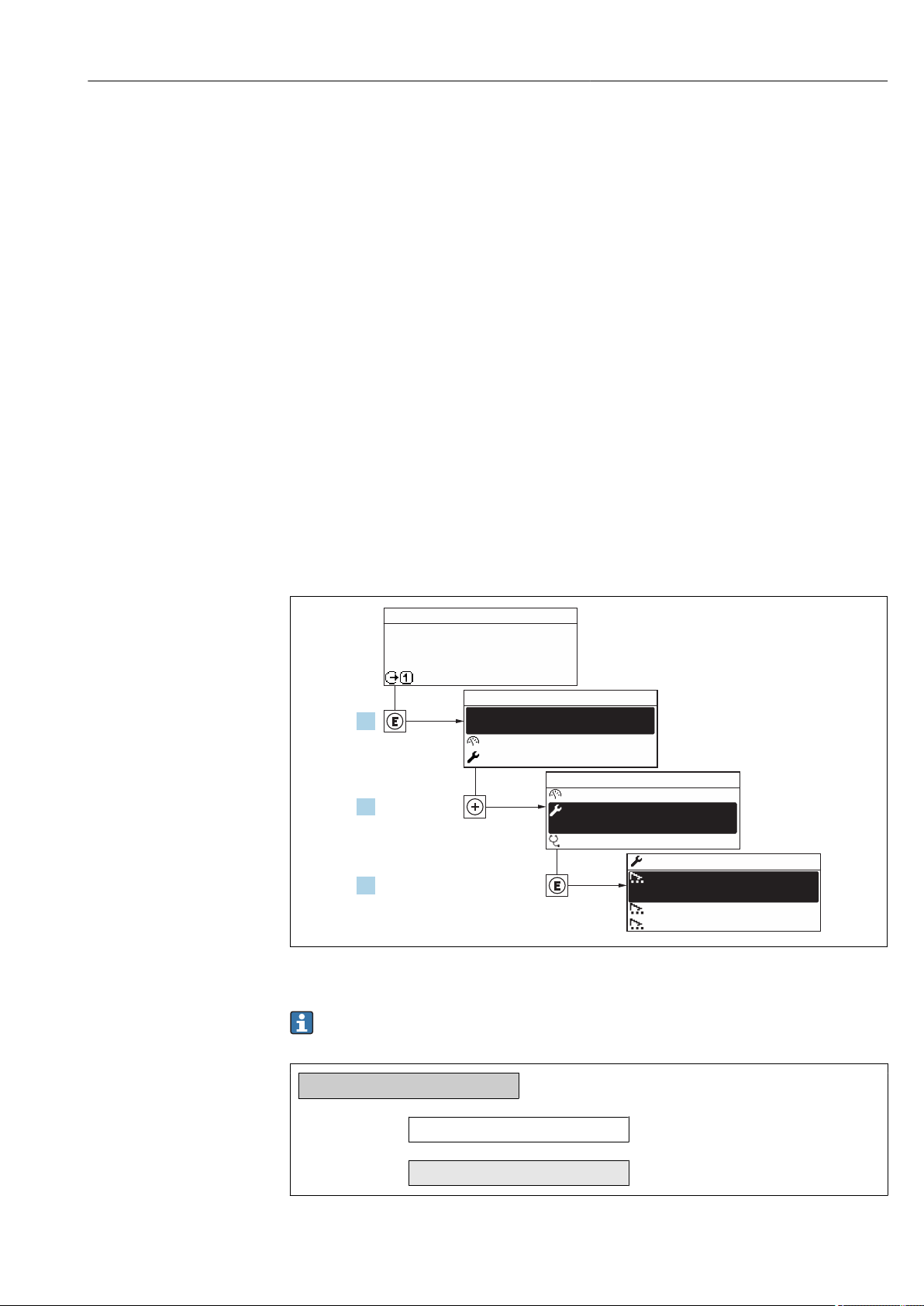
Proline Promass F 500 Modbus RS485 Commissioning
X X X X X X XX X
20.50
0104-1
XXXXXXXXX
XXXXXXXXX
mA
1.
2.
3.
Display/operat.
Setup
Diagnostic
Display/operat.
Setup
Main menu
English
Main menu
Status input
/ ../Setup
Display language
10 Commissioning
10.1 Function check
Before commissioning the measuring device:
Make sure that the post-installation and post-connection checks have been performed.
‣
• "Post-installation check" checklist → 36
• "Post-connection check" checklist → 62
10.2 Setting the operating language
Factory setting: English or ordered local language
The operating language can be set in FieldCare or DeviceCare: Operation → Display
language
10.3 Configuring the measuring device
• The Setup menuwith its guided wizards contains all the parameters needed for standard
operation.
• Navigation to the Setup menu
A0029700-EN
32 Taking the example of the local display
Endress+Hauser 93
Depending on the device version, not all submenus and parameters are available in
every device. The selection can vary depending on the order code.
Setup
Device tag
System units
‣
→ 95
→ 95
Page 94
Commissioning Proline Promass F 500 Modbus RS485
XXXXXXXXX
Communication
‣
Medium selection
‣
I/O configuration
‣
Current input 1 to n
‣
Status input 1 to n
‣
Current output 1 to n
‣
Pulse/frequency/switch output 1
‣
to n
Relay output 1 to n
‣
Double pulse output
‣
Display
‣
→ 96
→ 98
→ 99
→ 100
→ 101
→ 102
→ 105
→ 114
→ 116
→ 117
Low flow cut off
‣
Partially filled pipe detection
‣
Advanced setup
‣
→ 120
→ 121
→ 122
10.3.1 Defining the tag name
To enable fast identification of the measuring point within the system, you can enter a
unique designation using the Device tag parameter and thus change the factory setting.
A0029422
33 Header of the operational display with tag name
1 Tag name
Enter the tag name in the "FieldCare" operating tool → 87
Navigation
"Setup" menu → Device tag
94 Endress+Hauser
Page 95
Proline Promass F 500 Modbus RS485 Commissioning
Parameter overview with brief description
Parameter Description User entry Factory setting
Device tag Enter the name for the measuring point. Max. 32 characters such as
letters, numbers or special
characters (e.g. @, %, /).
Promass
10.3.2 Setting the system units
In the System units submenu the units of all the measured values can be set.
Depending on the device version, not all submenus and parameters are available in
every device. The selection can vary depending on the order code.
Navigation
"Setup" menu → System units
System units
‣
Mass flow unit
Mass unit
Volume flow unit
Volume unit
Corrected volume flow unit
Corrected volume unit
Density unit
Reference density unit
Temperature unit
Pressure unit
→ 95
→ 95
→ 96
→ 96
→ 96
→ 96
→ 96
→ 96
→ 96
→ 96
Parameter overview with brief description
Parameter Description Selection Factory setting
Mass flow unit Select mass flow unit.
Result
The selected unit applies for:
• Output
• Low flow cut off
• Simulation process variable
Mass unit Select mass unit. Unit choose list Country-specific:
Unit choose list Country-specific:
• kg/h
• lb/min
• kg
• lb
Endress+Hauser 95
Page 96

Commissioning Proline Promass F 500 Modbus RS485
Parameter Description Selection Factory setting
Volume flow unit Select volume flow unit.
Result
The selected unit applies for:
• Output
• Low flow cut off
• Simulation process variable
Volume unit Select volume unit. Unit choose list Country-specific:
Corrected volume flow unit Select corrected volume flow unit.
Result
The selected unit applies for:
Corrected volume flow parameter
(→ 143)
Corrected volume unit Select corrected volume unit. Unit choose list Country-specific:
Density unit Select density unit.
Result
The selected unit applies for:
• Output
• Simulation process variable
• Density adjustment (Expert menu)
Reference density unit Select reference density unit. Unit choose list Country-dependent
Temperature unit Select temperature unit.
Result
The selected unit applies for:
• Electronic temperature parameter
(6053)
• Maximum value parameter (6051)
• Minimum value parameter (6052)
• External temperature parameter (6080)
• Maximum value parameter (6108)
• Minimum value parameter (6109)
• Carrier pipe temperature parameter
(6027)
• Maximum value parameter (6029)
• Minimum value parameter (6030)
• Reference temperature parameter
(1816)
• Temperature parameter
Pressure unit Select process pressure unit.
Result
The unit is taken from:
• Pressure value parameter (→ 99)
• External pressure parameter
(→ 99)
• Pressure value
Unit choose list Country-specific:
• l/h
• gal/min (us)
• l (DN > 150 (6"): m³)
• gal (us)
Unit choose list Country-specific:
• Nl/h
• Sft³/min
• Nl
• Sft³
Unit choose list Country-specific:
• kg/l
• lb/ft³
• kg/Nl
• lb/Sft³
Unit choose list Country-specific:
• °C
• °F
Unit choose list Country-specific:
• bar a
• psi a
10.3.3 Configuring the communication interface
The Communication submenu guides you systematically through all the parameters that
have to be configured for selecting and setting the communication interface.
96 Endress+Hauser
Page 97
Proline Promass F 500 Modbus RS485 Commissioning
Navigation
"Setup" menu → Communication
Communication
‣
Bus address
Baudrate
Data transfer mode
Parity
Byte order
Failure mode
Parameter overview with brief description
Parameter Description User entry / Selection Factory setting
Bus address Enter device address. 1 to 247 247
Baudrate Define data transfer speed. • 1200 BAUD
• 2400 BAUD
• 4800 BAUD
• 9600 BAUD
• 19200 BAUD
• 38400 BAUD
• 57600 BAUD
• 115200 BAUD
Data transfer mode Select data transfer mode. • ASCII
• RTU
Parity Select parity bits. Picklist ASCII option:
• 0 = Even option
• 1 = Odd option
Picklist RTU option:
• 0 = Even option
• 1 = Odd option
• 2 = None / 1 stop bit option
• 3 = None / 2 stop bits
option
Byte order Select byte transmission sequence. • 0-1-2-3
• 3-2-1-0
• 1-0-3-2
• 2-3-0-1
Failure mode Select measured value output behavior when
a diagnostic message occurs via Modbus
communication.
1)
NaN
• NaN value
• Last valid value
19200 BAUD
RTU
Even
1-0-3-2
NaN value
→ 97
→ 97
→ 97
→ 97
→ 97
→ 97
1) Not a Number
Endress+Hauser 97
Page 98
Commissioning Proline Promass F 500 Modbus RS485
10.3.4 Selecting and setting the medium
The Select medium wizard submenu contains parameters that must be configured in
order to select and set the medium.
Navigation
"Setup" menu → Select medium
Medium selection
‣
Select medium
Select gas type
Reference sound velocity
Temperature coefficient sound velocity
Pressure compensation
Pressure value
External pressure
→ 99
→ 99
→ 99
→ 99
→ 99
→ 99
→ 99
98 Endress+Hauser
Page 99

Proline Promass F 500 Modbus RS485 Commissioning
Parameter overview with brief description
Parameter Prerequisite Description Selection / User
Select medium – Select medium type. • Liquid
• Gas
Select gas type The Gas option is selected in
the Select medium parameter.
Reference sound velocity In the Select gas type
parameter, the Others option
is selected.
Temperature coefficient sound
velocity
Pressure compensation – Select pressure compensation
Pressure value The Fixed value option is
External pressure The External value option is
The Others option is selected
in the Select gas type
parameter.
selected in the Pressure
compensation parameter.
selected in the Pressure
compensation parameter.
Select measured gas type. • Air
• Ammonia NH3
• Argon Ar
• Sulfur hexafluoride
SF6
• Oxygen O2
• Ozone O3
• Nitrogen oxide
NOx
• Nitrogen N2
• Nitrous oxide N2O
• Methane CH4
• Hydrogen H2
• Helium He
• Hydrogen chloride
HCl
• Hydrogen sulfide
H2S
• Ethylene C2H4
• Carbon dioxide
CO2
• Carbon monoxide
CO
• Chlorine Cl2
• Butane C4H10
• Propane C3H8
• Propylene C3H6
• Ethane C2H6
• Others
Enter sound velocity of gas at 0
°C (32 °F).
Enter temperature coefficient
for the gas sound velocity.
type.
Enter process pressure to be
used for pressure correction.
Shows the external process
pressure value.
1 to
99 999.9999 m/s
Positive floatingpoint number
• Off
• Fixed value
• External value
• Current input 1
• Current input 2
• Current input 3
Positive floatingpoint number
Positive floatingpoint number
Factory setting
entry
Liquid
Methane CH4
415.0 m/s
0 (m/s)/K
Off
*
*
*
0 bar
0 bar
* Visibility depends on order options or device settings
10.3.5 Displaying the I/O configuration
The I/O configuration submenu guides the user systematically through all the parameters
in which the configuration of the I/O modules is displayed.
Endress+Hauser 99
Page 100
Commissioning Proline Promass F 500 Modbus RS485
Navigation
"Setup" menu → I/O configuration
I/O configuration
‣
I/O module 1 to n terminal numbers
I/O module 1 to n information
I/O module 1 to n type
Apply I/O configuration
Conversion code
Parameter overview with brief description
Parameter Description User interface / Selection /
I/O module 1 to n terminal numbers Shows the terminal numbers used by the I/O
module.
I/O module 1 to n information Shows information of the plugged I/O
module.
I/O module 1 to n type Shows the I/O module type. • Off
Apply I/O configuration Apply parameterization of the freely
configurable I/O module.
Conversion code Enter the code in order to change the I/O
configuration.
• Not used
• 26-27 (I/O 1)
• 24-25 (I/O 2)
• 22-23 (I/O 3)
• 20-21 (I/O 4)
• Not plugged
• Invalid
• Not configurable
• Configurable
• Fieldbus
• Current output
• Current input
• Status input
• Pulse/frequency/switch
output
• No
• Yes
Positive integer 0
User entry
*
*
*
*
→ 100
→ 100
→ 100
→ 100
→ 100
Factory setting
–
–
*
Off
No
* Visibility depends on order options or device settings
10.3.6 Configuring the current input
The "Current input" wizard guides the user systematically through all the parameters that
have to be set for configuring the current input.
Navigation
"Setup" menu → Current input
Current input 1 to n
‣
Terminal number
100 Endress+Hauser
→ 101
 Loading...