

Page 1
Proline Promass F 300 Coriolis Flowmeter
EtherNet/IP
Operating Instructions Manual
BA01807O/06/EN/01.17
Valid as of version 01.00 zz (Device rmware)
71382409
MANUAL
p
c
e
o
e
K
v
e
r
t
i
g
h
t
w
h
i
l
n
e
n
f
f
ö
g
n
u
n
n
a
p
S
e
Page 2

•M
• To avoid danger to individuals or the facility, read the "Basic safety instructions" section
•
Important
ake sure the document is stored in a safe place such that it is always available when
working on or with the device.
carefully, as well as all other safety instructions in the document that are specific to
working procedures.
The manufacturer reserves the right to modify technical data without prior notice. Your
Endress+Hauser Sales Center will supply you with current information and updates to
these instructions.
All information and technical specications in this documentation have been carefully checked and compiled by
the author. However, we cannot completely exclude the possibility of errors. TechnipFMC is always grateful to be
informed of any errors. Contact us on the website.
Smith Meter® is a registered trademark of TechnipFMC.
Technical Support
Contact Information:
Field Service Response Center
24/7 Technical Support/Schedule a Technician: 1-844-798-3819
System Installation Supervision, Start-Up, and Commissioning Services Available
Customer Support
Contact Information:
Customer Service
TechnipFMC
1602 Wagner Avenue
Erie, Pennsylvania 16510 USA
P: +1 814 898-5000
F: +1 814 899-8927
TechnipFMC.com
Literature Library:
http://fmctechnologies.com/en/MeasurementSolutions/OnlineServices.aspx
Page 3

Proline Promass F 300 EtherNet/IP Table of contents
Table of contents
1 About this document ................ 6
1.1 Document function ..................... 6
1.2 Symbols used .......................... 6
1.2.1 Safety symbols .................. 6
1.2.2 Electrical symbols ................ 6
1.2.3 Communication symbols ........... 7
1.2.4 Tool symbols .................... 7
1.2.5 Symbols for
certain types of information ......... 7
1.2.6 Symbols in graphics ............... 8
1.3 Documentation ........................ 8
1.3.1 Standard documentation ........... 8
1.3.2 Supplementary device-dependent
documentation .................. 9
1.4 Registered trademarks ................... 9
2 Basic safety instructions ........... 10
2.1 Requirements for the personnel ........... 10
2.2 Designated use ....................... 10
2.3 Workplace safety ...................... 11
2.4 Operational safety ..................... 11
2.5 Product safety ........................ 12
2.6 IT security ........................... 12
2.7 Device-specific IT security ................ 12
2.7.1 Protecting access via hardware write
protection ..................... 12
2.7.2 Protecting access via a password .... 13
2.7.3 Access via fieldbus ............... 13
2.7.4 Access via Web server ............ 14
2.7.5 Access via CDI-RJ45 service
interface ...................... 14
3 Product description ................ 15
3.1 Product design ........................ 15
4 Incoming acceptance and product
identification ..................... 16
4.1 Incoming acceptance ................... 16
4.2 Product identification ................... 17
4.2.1 Transmitter nameplate ........... 18
4.2.2 Sensor nameplate ............... 19
4.2.3 Symbols on measuring device ...... 20
5 Storage and transport ............. 21
5.1 Storage conditions ..................... 21
5.2 Transporting the product ................ 21
5.2.1 Measuring devices without lifting
lugs ......................... 21
5.2.2 Measuring devices with lifting lugs .. 22
5.2.3 Transporting with a fork lift ........ 22
5.3 Packaging disposal ..................... 22
6 Installation ....................... 23
6.1 Installation conditions .................. 23
6.1.1 Mounting position ............... 23
6.1.2 Requirements from environment and
process ....................... 26
6.1.3 Special mounting instructions ...... 28
6.2 Mounting the measuring device ........... 30
6.2.1 Required tools .................. 30
6.2.2 Preparing the measuring device ..... 30
6.2.3 Mounting the measuring device ..... 30
6.2.4 Turning the transmitter housing .... 31
6.2.5 Turning the display module ........ 31
6.3 Post-installation check .................. 32
7 Electrical connection .............. 33
7.1 Connection conditions .................. 33
7.1.1 Required tools .................. 33
7.1.2 Requirements for connecting cable ... 33
7.1.3 Terminal assignment ............. 36
7.1.4 Device plugs available ............ 36
7.1.5 Pin assignment of device plug ...... 36
7.1.6 Preparing the measuring device ..... 37
7.2 Connecting the measuring device .......... 37
7.2.1 Connecting the transmitter ........ 37
7.2.2 Integrating the transmitter into a
network ...................... 41
7.2.3 Connecting the remote display and
operating module DKX001 ........ 43
7.3 Ensure potential equalization ............. 43
7.3.1 Requirements .................. 43
7.4 Special connection instructions ............ 44
7.4.1 Connection examples ............. 44
7.5 Hardware settings ..................... 47
7.5.1 Setting the device address ......... 47
7.5.2 Activating the default IP address .... 48
7.6 Ensuring the degree of protection .......... 49
7.7 Post-connection check .................. 49
8 Operation options ................. 50
8.1 Overview of operation options ............ 50
8.2 Structure and function of the operating
menu .............................. 51
8.2.1 Structure of the operating menu .... 51
8.2.2 Operating philosophy ............ 53
3
Page 4

Table of contents Proline Promass F 300 EtherNet/IP
8.3 Access to the operating menu via the local
display ............................. 54
8.3.1 Operational display .............. 54
8.3.2 Navigation view ................ 56
8.3.3 Editing view ................... 58
8.3.4 Operating elements .............. 60
8.3.5 Opening the context menu ......... 61
8.3.6 Navigating and selecting from list ... 62
8.3.7 Calling the parameter directly ...... 63
8.3.8 Calling up help text .............. 63
8.3.9 Changing the parameters ......... 64
8.3.10 User roles and related access
authorization .................. 64
8.3.11 Disabling write protection via access
code ......................... 65
8.3.12 Enabling and disabling the keypad
lock ......................... 65
8.4 Access to the operating menu via the Web
browser ............................. 66
8.4.1 Function range ................. 66
8.4.2 Prerequisites ................... 66
8.4.3 Establishing a connection ......... 68
8.4.4 Logging on .................... 70
8.4.5 User interface .................. 71
8.4.6 Disabling the Web server .......... 72
8.4.7 Logging out .................... 72
8.5 Access to the operating menu via the
operating tool ........................ 73
8.5.1 Connecting the operating tool ...... 73
8.5.2 FieldCare ..................... 77
8.5.3 DeviceCare .................... 78
9 System integration ................ 79
9.1 Overview of device description files ......... 79
9.1.1 Current version data for the device ... 79
9.1.2 Operating tools ................. 79
9.2 Overview of system files ................. 80
9.3 Integrating the measuring device in the
system ............................. 80
9.4 Cyclic data transmission ................ 80
9.4.1 Block model ................... 80
9.4.2 Input and output groups .......... 82
9.5 Diagnostic information via EtherNet/IP ..... 93
10 Commissioning .................... 98
10.1 Function check ....................... 98
10.2 Switching on the measuring device ......... 98
10.3 Connecting via FieldCare ................ 98
10.4 Setting the operating language ............ 98
10.5 Configuring the measuring device .......... 99
10.5.1 Defining the tag name ........... 101
10.5.2 Setting the system units ......... 101
10.5.3 Configuring the communication
interface ..................... 103
10.5.4 Selecting and setting the medium .. 105
10.5.5 Displaying the I/O configuration ... 107
10.5.6 Configuring the current input ..... 107
10.5.7 Configuring the status input ...... 109
10.5.8 Configuring the current output .... 109
10.5.9 Configuring the pulse/frequency/
switch output ................. 114
10.5.10 Configuring the relay output ...... 125
10.5.11 Configuring the local display ...... 128
10.5.12 Configuring the low flow cut off .... 139
10.5.13 Configuring the partial filled pipe
detection .................... 140
10.6 Advanced settings .................... 141
10.6.1 Using the parameter to enter the
access code ................... 142
10.6.2 Calculated values ............... 142
10.6.3 Carrying out a sensor adjustment ... 143
10.6.4 Configuring the totalizer ......... 144
10.6.5 Carrying out additional display
configurations ................. 147
10.6.6 WLAN configuration ............ 158
10.6.7 Configuration management ....... 160
10.6.8 Using parameters for device
administration ................ 161
10.7 Simulation .......................... 163
10.8 Protecting settings from unauthorized
access ............................. 167
10.8.1 Write protection via access code ... 167
10.8.2 Write protection via write protection
switch ....................... 169
11 Operation ....................... 170
11.1 Reading the device locking status ......... 170
11.2 Adjusting the operating language ......... 170
11.3 Configuring the display ................ 170
11.4 Reading measured values ............... 170
11.4.1 "Measured variables" submenu ..... 171
11.4.2 "Totalizer" submenu ............. 173
11.4.3 "Input values" submenu .......... 173
11.4.4 Output values ................. 175
11.5 Adapting the measuring device to the process
conditions .......................... 177
11.6 Performing a totalizer reset ............. 177
11.6.1 Function scope of the "Control
Totalizer" parameter ............ 178
11.6.2 Function scope of the "Reset all
totalizers" parameter ............ 178
11.7 Showing data logging ................. 179
12 Diagnostics and troubleshooting .. 184
12.1 General troubleshooting ................ 184
12.2 Diagnostic information via light emitting
diodes ............................. 187
12.2.1 Transmitter ................... 187
4
Page 5

Proline Promass F 300 EtherNet/IP Table of contents
12.3 Diagnostic information on local display ..... 189
12.3.1 Diagnostic message ............. 189
12.3.2 Calling up remedial measures ..... 191
12.4 Diagnostic information in the Web browser . 192
12.4.1 Diagnostic options .............. 192
12.4.2 Calling up remedy information .... 193
12.5 Diagnostic information in DeviceCare or
FieldCare ........................... 193
12.5.1 Diagnostic options .............. 193
12.5.2 Calling up remedy information .... 194
12.6 Diagnostic information via communication
interface ........................... 194
12.6.1 Reading out diagnostic information 194
12.7 Adapting the diagnostic information ...... 195
12.7.1 Adapting the diagnostic behavior ... 195
12.8 Overview of diagnostic information ....... 195
12.8.1 Diagnostic of sensor ............ 195
12.8.2 Diagnostic of electronic .......... 197
12.8.3 Diagnostic of configuration ....... 201
12.8.4 Diagnostic of process ............ 205
12.9 Pending diagnostic events .............. 209
12.10 Diagnostic list ....................... 210
12.11 Event logbook ....................... 211
12.11.1 Reading out the event logbook ..... 211
12.11.2 Filtering the event logbook ....... 211
12.11.3 Overview of information events .... 212
12.12 Resetting the measuring device .......... 213
12.12.1 Function scope of the "Device reset"
parameter .................... 213
12.13 Device information ................... 214
12.14 Firmware history ..................... 215
15.1.2 For the sensor ................. 220
15.2 Communication-specific accessories ....... 220
15.3 Service-specific accessories .............. 220
15.4 System components ................... 221
16 Technical data ................... 222
16.1 Application ......................... 222
16.2 Function and system design ............. 222
16.3 Input .............................. 223
16.4 Output ............................ 226
16.5 Power supply ........................ 231
16.6 Performance characteristics ............. 232
16.7 Installation ......................... 237
16.8 Environment ........................ 237
16.9 Process ............................ 238
16.10 Mechanical construction ............... 242
16.11 Operability ......................... 246
16.12 Certificates and approvals .............. 251
16.13 Application packages .................. 253
16.14 Accessories ......................... 255
16.15 Supplementary documentation ........... 255
Index ................................. 257
13 Maintenance .................... 216
13.1 Maintenance tasks .................... 216
13.1.1 Exterior cleaning ............... 216
13.1.2 Interior cleaning ............... 216
13.2 Measuring and test equipment ........... 216
13.3 Endress+Hauser services ............... 216
14 Repairs .......................... 217
14.1 General notes ....................... 217
14.1.1 Repair and conversion concept ..... 217
14.1.2 Notes for repair and conversion .... 217
14.2 Spare parts ......................... 217
14.3 Endress+Hauser services ............... 217
14.4 Return ............................. 217
14.5 Disposal ........................... 218
14.5.1 Removing the measuring device .... 218
14.5.2 Disposing of the measuring device .. 218
15 Accessories ...................... 219
15.1 Device-specific accessories .............. 219
15.1.1 For the transmitter ............. 219
5
Page 6
About this document Proline Promass F 300 EtherNet/IP
DANGER
WARNING
CAUTION
NOTICE
1 About this document
1.1 Document function
These Operating Instructions contain all the information that is required in various phases
of the life cycle of the device: from product identification, incoming acceptance and
storage, to mounting, connection, operation and commissioning through to
troubleshooting, maintenance and disposal.
1.2 Symbols used
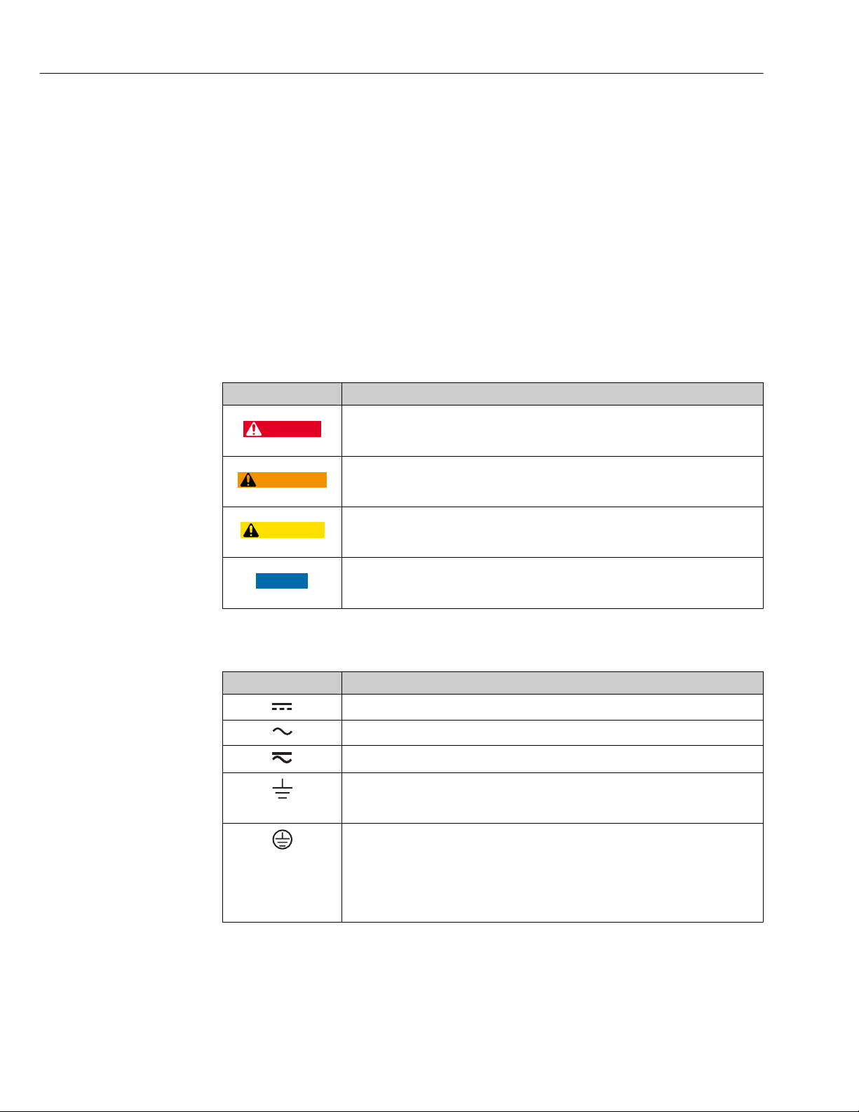
1.2.1 Safety symbols
Symbol Meaning
DANGER!
This symbol alerts you to a dangerous situation. Failure to avoid this situation will
result in serious or fatal injury.
WARNING!
This symbol alerts you to a dangerous situation. Failure to avoid this situation can
result in serious or fatal injury.
CAUTION!
This symbol alerts you to a dangerous situation. Failure to avoid this situation can
result in minor or medium injury.
NOTE!
This symbol contains information on procedures and other facts which do not result in
personal injury.
1.2.2 Electrical symbols
Symbol Meaning
Direct current
Alternating current
Direct current and alternating current
Ground connection
A grounded terminal which, as far as the operator is concerned, is grounded via a
grounding system.
Protective Earth (PE)
A terminal which must be connected to ground prior to establishing any other
connections.
The ground terminals are situated inside and outside the device:
• Inner ground terminal: Connects the protectiv earth to the mains supply.
• Outer ground terminal: Connects the device to the plant grounding system.
6
Page 7
Proline Promass F 300 EtherNet/IP About this document
A
1.
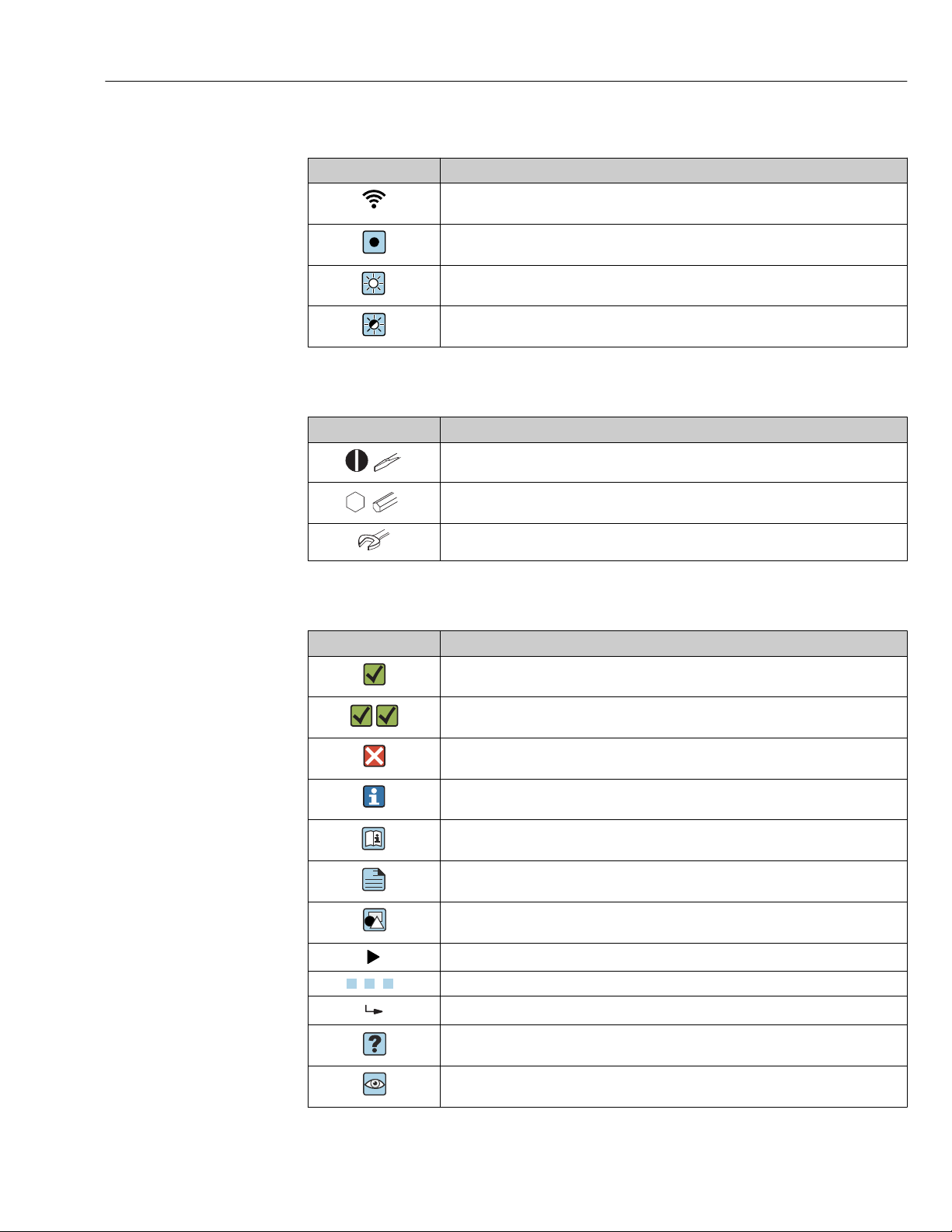
1.2.3 Communication symbols
Symbol Meaning
Wireless Local Area Network (WLAN)
Communication via a wireless, local network.
LED
Light emitting diode is off.
LED
Light emitting diode is on.
LED
Light emitting diode is flashing.
1.2.4 Tool symbols
Symbol Meaning
Flat blade screwdriver
Allen key
Open-ended wrench
1.2.5 Symbols for certain types of information
Symbol Meaning
Permitted
Procedures, processes or actions that are permitted.
Preferred
Procedures, processes or actions that are preferred.
Forbidden
Procedures, processes or actions that are forbidden.
Tip
Indicates additional information.
Reference to documentation.
Reference to page.
Reference to graphic.
Notice or individual step to be observed.
, 2., 3.… Series of steps.
Result of a step.
Help in the event of a problem.
Visual inspection.
7
Page 8
About this document Proline Promass F 300 EtherNet/IP
1.
-
.
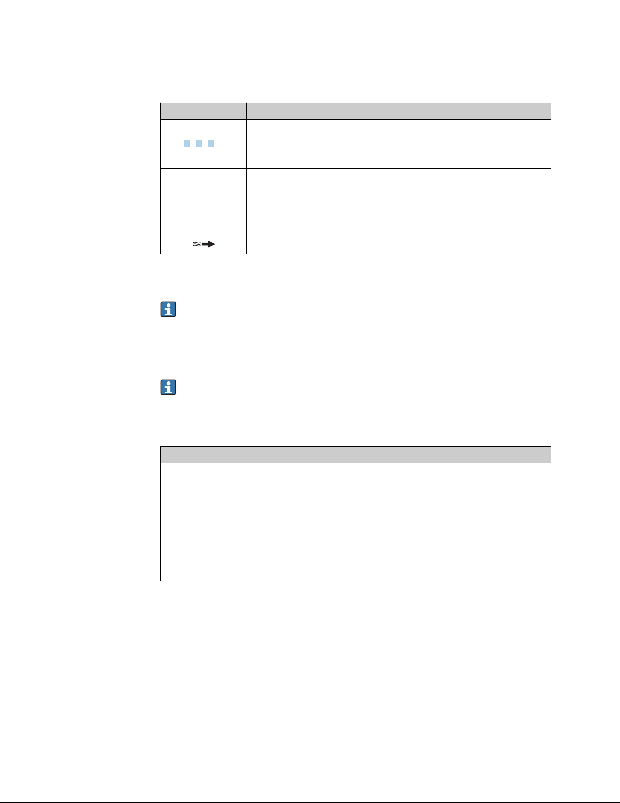
1.2.6 Symbols in graphics
Symbol Meaning
1, 2, 3, ... Item numbers
, 2., 3., … Series of steps
A, B, C, ... Views
A-A, B-B, C-C, ... Sections
Hazardous area
Safe area (non-hazardous area)
Flow direction
1.3 Documentation
For an overview of the scope of the associated Technical Documentation, refer to the
following:
• The W@M Device Viewer : Enter the serial number from the nameplate
(www.endress.com/deviceviewer)
• The Endress+Hauser Operations App: Enter the serial number from the nameplate
or scan the 2-D matrix code (QR code) on the nameplate.
For a detailed list of the individual documents along with the documentation code
→ 255
1.3.1 Standard documentation
Document type Purpose and content of the document
Technical Information Planning aid for your device
The document contains all the technical data on the device and provides
an overview of the accessories and other products that can be ordered for
the device.
Sensor Brief Operating Instructions Guides you quickly to the 1st measured value - Part 1
The Sensor Brief Operating Instructions are aimed at specialists with
responsibility for installing the measuring device.
• Incoming acceptance and product identification
• Storage and transport
• Installation
8
Page 9
Proline Promass F 300 EtherNet/IP About this document
Document type Purpose and content of the document
Transmitter Brief Operating
Instructions
Description of Device Parameters Reference for your parameters
Guides you quickly to the 1st measured value - Part 2
The Transmitter Brief Operating Instructions are aimed at specialists with
responsibility for commissioning, configuring and parameterizing the
measuring device (until the first measured value).
• Product description
• Installation
• Electrical connection
• Operation options
• System integration
• Commissioning
• Diagnostic information
The document provides a detailed explanation of each individual
parameter in the Expert operating menu. The description is aimed at
those who work with the device over the entire life cycle and perform
specific configurations.
1.3.2 Supplementary device-dependent documentation
Additional documents are supplied depending on the device version ordered: Always
comply strictly with the instructions in the supplementary documentation. The
supplementary documentation is an integral part of the device documentation.
1.4 Registered trademarks
EtherNet/IP™
Trademark of ODVA, Inc.
TRI-CLAMP®
Registered trademark of Ladish & Co., Inc., Kenosha, USA
9
Page 10

Basic safety instructions Proline Promass F 300 EtherNet/IP
2 Basic safety instructions
2.1 Requirements for the personnel
The personnel for installation, commissioning, diagnostics and maintenance must fulfill
the following requirements:
Trained, qualified specialists must have a relevant qualification for this specific function
‣
and task.
Are authorized by the plant owner/operator.
‣
Are familiar with federal/national regulations.
‣
Before starting work, read and understand the instructions in the manual and
‣
supplementary documentation as well as the certificates (depending on the
application).
Follow instructions and comply with basic conditions.
‣
The operating personnel must fulfill the following requirements:
Are instructed and authorized according to the requirements of the task by the facility's
‣
owner-operator.
Follow the instructions in this manual.
‣
2.2 Designated use
Application and media
The measuring device described in these Brief Operating Instructions is intended only for
flow measurement of liquids and gases.
Depending on the version ordered, the measuring device can also measure potentially
explosive, flammable, poisonous and oxidizing media.
Measuring devices for use in hazardous areas, in hygienic applications or where there is an
increased risk due to process pressure, are labeled accordingly on the nameplate.
To ensure that the measuring device remains in proper condition for the operation time:
Keep within the specified pressure and temperature range.
‣
Only use the measuring device in full compliance with the data on the nameplate and
‣
the general conditions listed in the Operating Instructions and supplementary
documentation.
Based on the nameplate, check whether the ordered device is permitted for the
‣
intended use in the hazardous area (e.g. explosion protection, pressure vessel safety).
Use the measuring device only for media to which the process-wetted materials are
‣
sufficiently resistant.
If the measuring device is not operated at atmospheric temperature, compliance with
‣
the relevant basic conditions specified in the associated device documentation is
absolutely essential: "Documentation" section→ 8.
Protect the measuring device permanently against corrosion from environmental
‣
influences.
10
Incorrect use
Non-designated use can compromise safety. The manufacturer is not liable for damage
caused by improper or non-designated use.
Page 11
Proline Promass F 300 EtherNet/IP Basic safety instructions
WARNING
L
Danger of breakage due to corrosive or abrasive fluids!
Verify the compatibility of the process fluid with the sensor material.
‣
Ensure the resistance of all fluid-wetted materials in the process.
‣
Keep within the specified pressure and temperature range.
‣
NOTICE
Verification for borderline cases:
For special fluids and fluids for cleaning, Endress+Hauser is glad to provide assistance
‣
in verifying the corrosion resistance of fluid-wetted materials, but does not accept any
warranty or liability as minute changes in the temperature, concentration or level of
contamination in the process can alter the corrosion resistance properties.
Residual risks
WARNING
L
The electronics and the medium may cause the surfaces to heat up. This presents a
burn hazard!
For elevated fluid temperatures, ensure protection against contact to prevent burns.
‣
WARNING
L
Danger of housing breaking due to measuring tube breakage!
In the event of a measuring tube breakage for a device version without rupture disk it is
‣
possible for the pressure loading capacity of the sensor housing to be exceeded. This
can lead to rupture or failure of the sensor housing.
2.3 Workplace safety
For work on and with the device:
Wear the required personal protective equipment according to federal/national
‣
regulations.
For welding work on the piping:
Do not ground the welding unit via the measuring device.
‣
If working on and with the device with wet hands:
Due to the increased risk of electric shock, gloves must be worn.
‣
2.4 Operational safety
Risk of injury.
Operate the device in proper technical condition and fail-safe condition only.
‣
The operator is responsible for interference-free operation of the device.
‣
Conversions to the device
Unauthorized modifications to the device are not permitted and can lead to unforeseeable
dangers.
If, despite this, modifications are required, consult with Endress+Hauser.
‣
Repair
To ensure continued operational safety and reliability,
Carry out repairs on the device only if they are expressly permitted.
‣
Observe federal/national regulations pertaining to repair of an electrical device.
‣
11
Page 12
Basic safety instructions Proline Promass F 300 EtherNet/IP
Use original spare parts and accessories from Endress+Hauser only.
‣
2.5 Product safety
This measuring device is designed in accordance with good engineering practice to meet
state-of-the-art safety requirements, has been tested, and left the factory in a condition in
which it is safe to operate.
It meets general safety standards and legal requirements. It also complies with the EU
directives listed in the device-specific EU Declaration of Conformity. Endress+Hauser
confirms this by affixing the CE mark to the device.
2.6 IT security
We only provide a warranty if the device is installed and used as described in the
Operating Instructions. The device is equipped with security mechanisms to protect it
against any inadvertent changes to the device settings.
IT security measures in line with operators' security standards and designed to provide
additional protection for the device and device data transfer must be implemented by the
operators themselves.
2.7 Device-specific IT security
The device offers a range of specific functions to support protective measures on the
operator's side. These functions can be configured by the user and guarantee greater inoperation safety if used correctly. An overview of the most important functions is provided
in the following section.
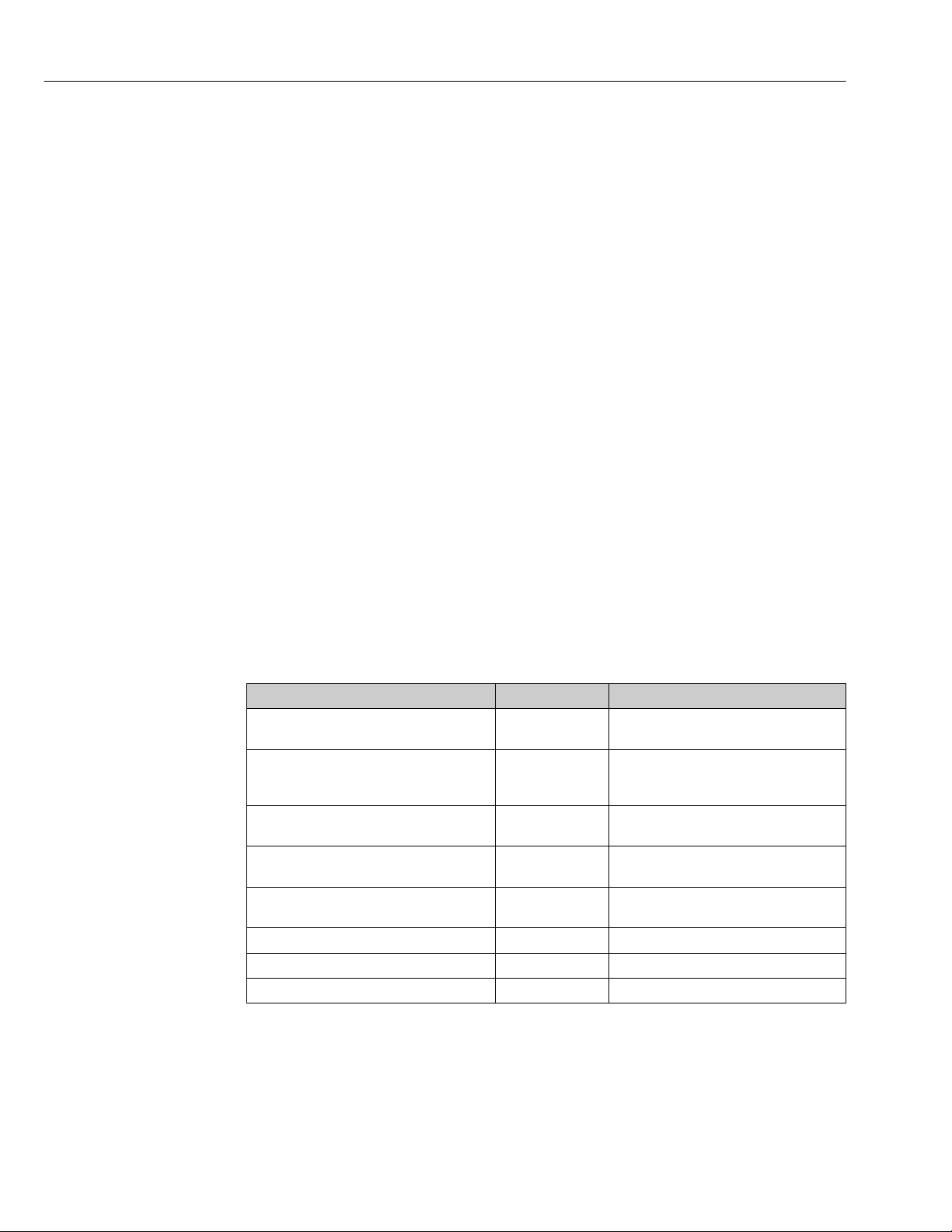
Function/interface Factory setting Recommendation
Write protection via hardware write
protection switch → 12
Access code
(also applies for Web server login or
FieldCare connection) → 13
WLAN
(order option in display module)
WLAN security mode Enabled (WPA2-
WLAN passphrase
(password) → 13
WLAN mode Access Point Individually following risk assessment.
Web server→ 14 Enabled. Individually following risk assessment.
CDI-RJ45 service interface → 14 – Individually following risk assessment.
Not enabled. Individually following risk assessment.
Not enabled
(0000).
Enabled. Individually following risk assessment.
PSK)
Serial number Assign an individual access code during
Assign an individual access code during
commissioning.
Do not change.
commissioning.
12
2.7.1 Protecting access via hardware write protection
Write access to the device parameters via the local display, Web browser or operating tool
(e.g. FieldCare, DeviceCare) can be disabled via a write protection switch (DIP switch on
Page 13

Proline Promass F 300 EtherNet/IP Basic safety instructions
the motherboard). When hardware write protection is enabled, only read access to the
parameters is possible.
Hardware write protection is disabled when the device is delivered → 169.
2.7.2 Protecting access via a password
Different passwords are available to protect write access to the device parameters or access
to the device via the WLAN interface.
• User-specific access code
Protect write access to the device parameters via the local display, Web browser or
operating tool (e.g. FieldCare, DeviceCare). Access authorization is clearly regulated
through the use of a user-specific access code.
• WLAN passphrase
The network key protects a connection between an operating unit (e.g. notebook or
tablet) and the device via the WLAN interface which can be ordered as an option.
User-specific access code
Write access to the device parameters via the local display, Web browser or operating tool
(e.g. FieldCare, DeviceCare) can be protected by the modifiable, user-specific access code
(→ 167).
When the device is delivered, the device does not have an access code and is equivalent to
0000 (open).
WLAN passphrase
A connection between an operating unit (e.g. notebook or tablet) and the device via the
WLAN interface (→ 75) which can be ordered as an option is protected by the
network key. The WLAN authentication of the network key complies with the IEEE 802.11
standard.
When the device is delivered, the network key is pre-defined depending on the device. It
can be changed via the WLAN settings submenu in the WLAN passphrase parameter
(→ 159).
General notes on the use of passwords
• The access code and network key supplied with the device should be changed during
commissioning.
• Follow the general rules for generating a secure password when defining and managing
the access code or network key.
• The user is responsible for the management and careful handling of the access code and
network key.
• For information on configuring the access code or on what to do if you lose the
password, see the "Write protection via access code" section → 167
2.7.3 Access via fieldbus
When communicating via fieldbus, access to the device parameters can be restricted to
"Read only" access. The option can be changed in the Fieldbus writing access parameter.
This does not affect cyclic measured value transmission to the higher-order system, which
is always guaranteed.
For detailed information, see the "Description of Device Parameters" document
pertaining to the device → 255
13
Page 14

Basic safety instructions Proline Promass F 300 EtherNet/IP
2.7.4 Access via Web server
The device can be operated and configured via a Web browser with the integrated Web
server (→ 66). The connection is via the service interface (CDI-RJ45), the connection
for EtherNet/IP signal transmission (RJ45 connector) or the WLAN interface.
The Web server is enabled when the device is delivered. The Web server can be disabled if
necessary (e.g. after commissioning) via the Web server functionality parameter.
The device and status information can be hidden on the login page. This prevents
unauthorized access to the information.
For detailed information, see the "Description of Device Parameters" document
pertaining to the device → 255
2.7.5 Access via CDI-RJ45 service interface
The device can be connected to a network via the CDI-RJ45 service interface. Devicespecific functions guarantee the secure operation of the device in a network.
It is advisable to take relevant security concepts into consideration, such as those issued by
the Federal Office for Information Security. This includes organizational security measures
such as the assignment of access authorization as well as technical measures such as
network segmentation.
The device can be integrated in a ring topology. The device is integrated via the
terminal connection for signal transmission (output 1) and the connection to the
service interface (CDI-RJ45) → 42.
14
Page 15
Proline Promass F 300 EtherNet/IP Product description
5
4
Nicht unter
Spannung öffnen
Do not open when
energized
Ne pas ouvrir
sous tension
Power
I/O
N
i
c
h
t
u
n
t
e
r
a
r
e
ö
f
f
n
e
n
D
i
s
p
l
a
y
+
E
ESC
–
1
2
3
3 Product description
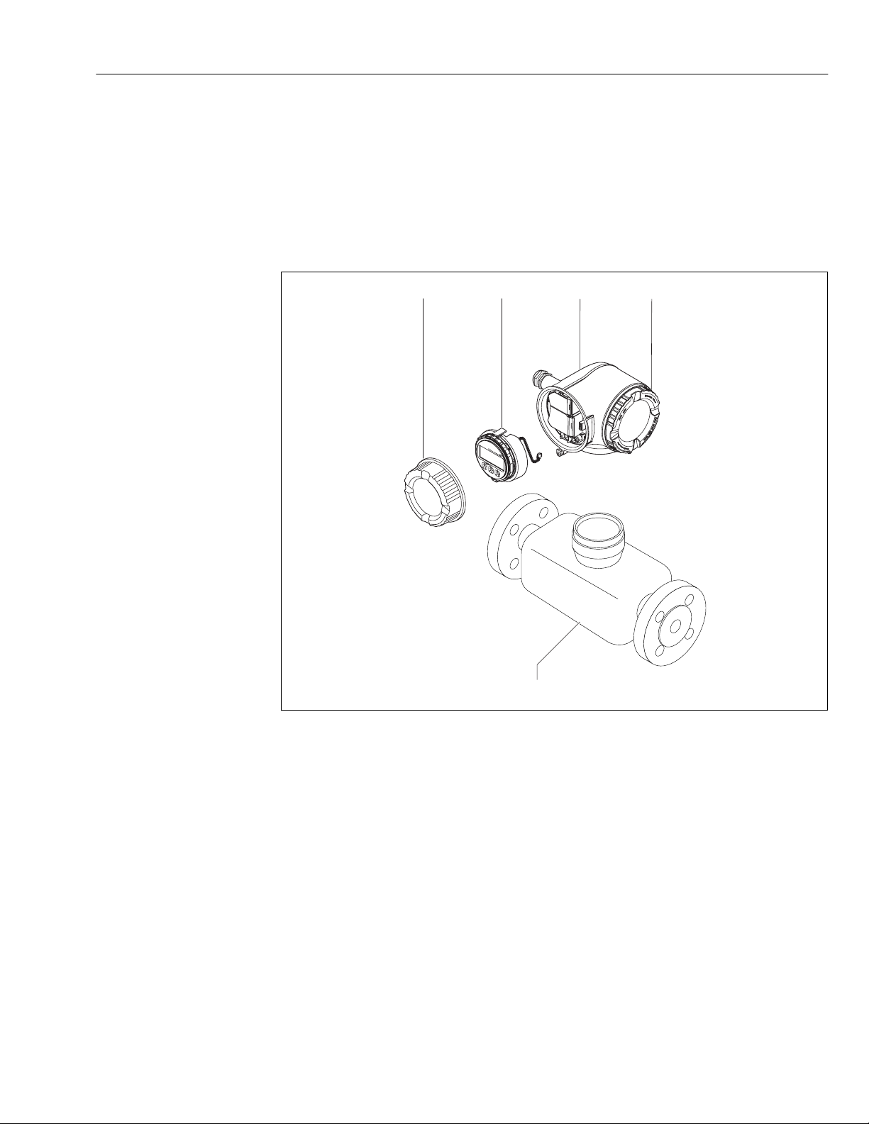
The device consists of a transmitter and a sensor.
The device is available as a compact version:
The transmitter and sensor form a mechanical unit.
3.1 Product design
A0029586
1 Important components of a measuring device
1 Connection compartment cover
2 Display module
3 Transmitter housing
4 Electronics compartment cover
5 Sensor
15
Page 16
Incoming acceptance and product identification Proline Promass F 300 EtherNet/IP
1
2
1
2
Order code:
Ser. no.:
Ext. ord. cd.:
i
i
Date:
4 Incoming acceptance and product
identification
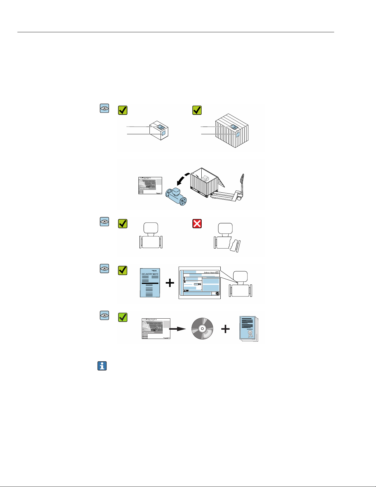
4.1 Incoming acceptance
Are the order codes on the
A0028673
delivery note (1) and the
product sticker (2) identical?
Are the goods undamaged?
A0028673
Do the nameplate data
A0028673
match the ordering
information on the delivery
note?
Is the CD-ROM with the
A0028673
Technical Documentation
(depends on device version)
and documents present?
• If one of the conditions is not satisfied, contact your Endress+Hauser Sales Center.
• Depending on the device version, the CD-ROM might not be part of the delivery!
The Technical Documentation is available via the Internet or via the Endress+Hauser
Operations App, see the "Product identification" section → 17.
16
Page 17

Proline Promass F 300 EtherNet/IP Incoming acceptance and product identification
4.2 Product identification
The following options are available for identification of the measuring device:
• Nameplate specifications
• Order code with breakdown of the device features on the delivery note
• Enter serial numbers from nameplates in W@M Device Viewer
(www.endress.com/deviceviewer): All information about the measuring device is
displayed.
• Enter the serial number from the nameplates into the Endress+Hauser Operations App
or scan the 2-D matrix code (QR code) on the nameplate with the Endress+Hauser
Operations App: all the information for the measuring device is displayed.
For an overview of the scope of the associated Technical Documentation, refer to the
following:
• The chapters "Additional standard documentation on the device" → 8 and
"Supplementary device-dependent documentation" → 9
• The W@M Device Viewer: Enter the serial number from the nameplate
(www.endress.com/deviceviewer)
• The Endress+Hauser Operations App: Enter the serial number from the nameplate or
scan the 2-D matrix code (QR code) on the nameplate.
17
Page 18
Incoming acceptance and product identification Proline Promass F 300 EtherNet/IP
Order code:
Ser. no.:
Ext. ord. cd.:
i
i
Date:
1 2 3 4 5
20
19
6
7
8
9
13 12 1011
18
17
16
14
15
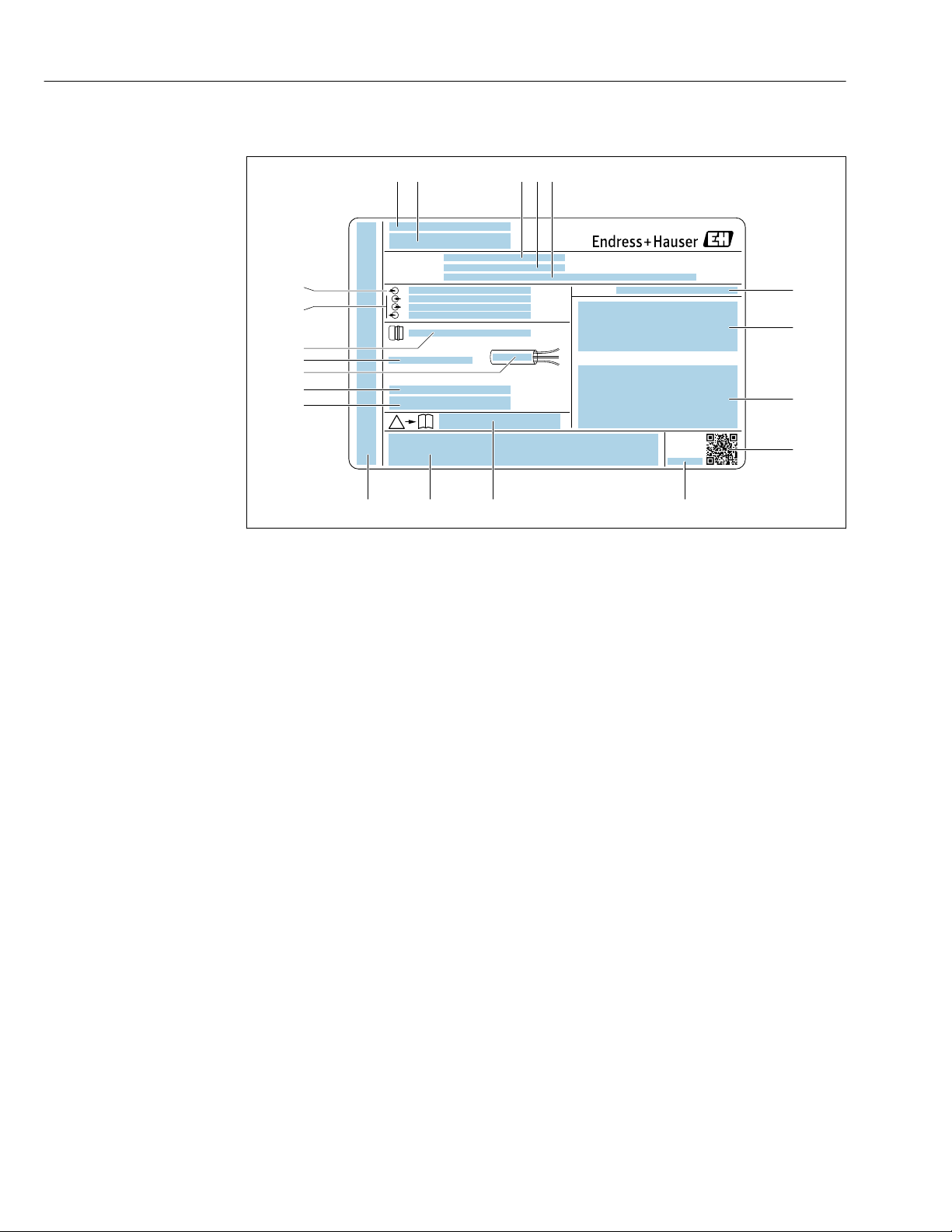
4.2.1 Transmitter nameplate
2 Example of a transmitter nameplate
1 Manufacturing location
2 Name of the transmitter
3 Order code
4 Serial number (ser. no.)
5 Extended order code (Ext. ord. cd.)
6 Degree of protection
7 Space for approvals: use in hazardous areas
8 Electrical connection data: available inputs and outputs
9 2-D matrix code
10 Manufacturing date: year-month
11 Document number of safety-related supplementary documentation
12 Space for approvals and certificates: e.g. CE mark, C-Tick
13 Space for degree of protection of connection and electronics compartment when used in hazardous areas
14 Firmware version (FW) and device revision (Dev.Rev.) from the factory
15 Space for additional information in the case of special products
16 Permitted temperature range for cable
17 Permitted ambient temperature (Ta)
18 Information on cable gland
19 Available inputs and outputs, supply voltage
20 Electrical connection data: supply voltage
A0029192
18
Page 19
Proline Promass F 300 EtherNet/IP Incoming acceptance and product identification
Order code:
Ser. no.:
Ext. ord. cd.:
i
i
Date:
1
3
4
5
6
7
8
9
2
10
1112
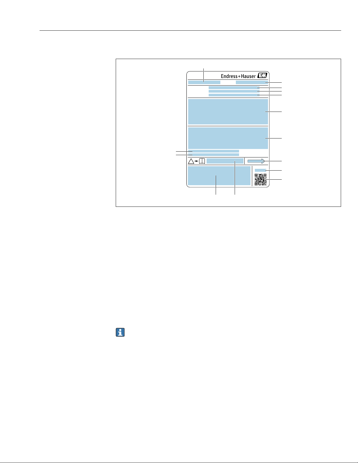
4.2.2 Sensor nameplate
A0029199
3 Example of a sensor nameplate
1 Name of the sensor
2 Manufacturing location
3 Order code
4 Serial number (ser. no.)
5 Extended order code (Ext. ord. cd.)
6 Nominal diameter of the sensor; flange nominal diameter/nominal pressure; sensor test pressure; medium
temperature range; material of measuring tube and manifold; sensor-specific information: e.g. pressure range
of secondary containment, wide-range density specification (special density calibration)
7 Approval information for explosion protection, Pressure Equipment Directive and degree of protection
8 Flow direction
9 Manufacturing date: year-month
10 2-D matrix code
11 Document number of safety-related supplementary documentation
12 CE mark, C-Tick
13 Surface roughness
14 Permitted ambient temperature (Ta)
Order code
The measuring device is reordered using the order code.
Extended order code
• The device type (product root) and basic specifications (mandatory features) are
always listed.
• Of the optional specifications (optional features), only the safety and approvalrelated specifications are listed (e.g. LA). If other optional specifications are also
ordered, these are indicated collectively using the # placeholder symbol (e.g. #LA#).
• If the ordered optional specifications do not include any safety and approval-related
specifications, they are indicated by the + placeholder symbol (e.g. XXXXXX-ABCDE
+).
19
Page 20
Incoming acceptance and product identification Proline Promass F 300 EtherNet/IP
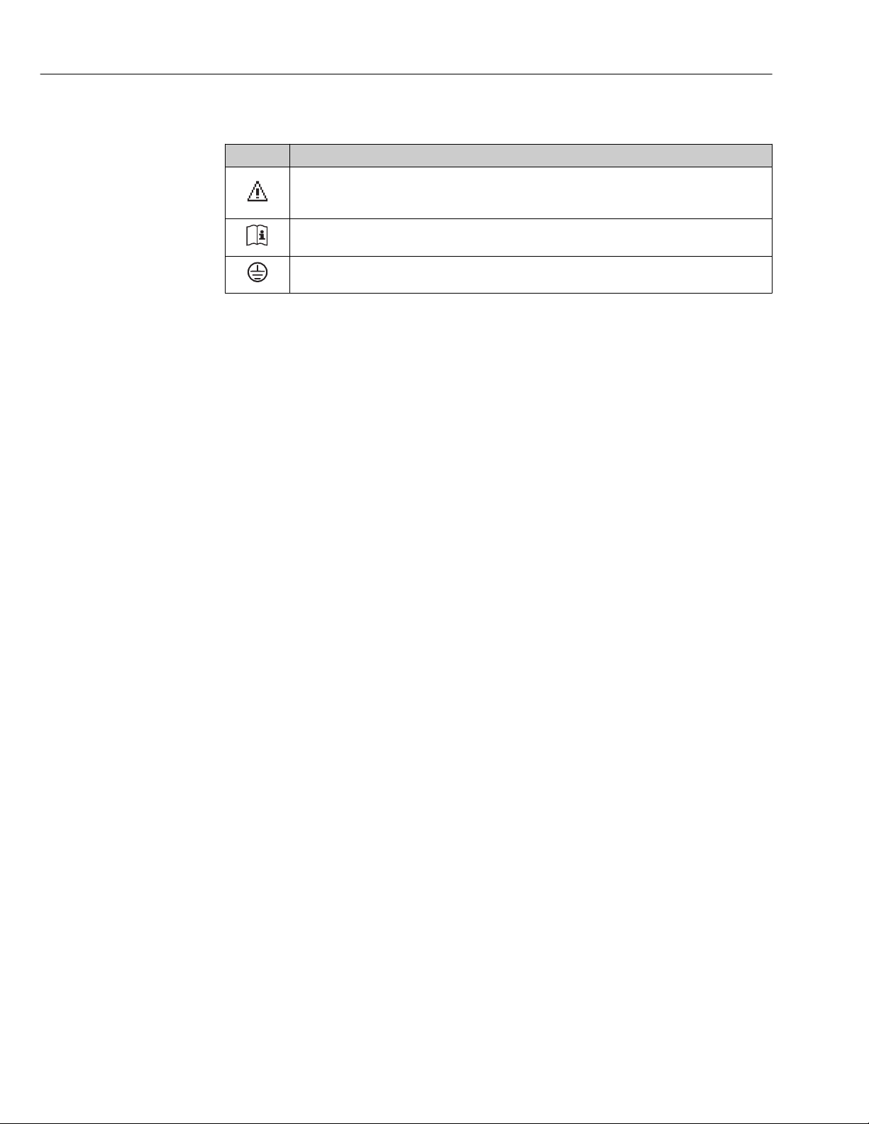
4.2.3 Symbols on measuring device
Symbol Meaning
WARNING!
This symbol alerts you to a dangerous situation. Failure to avoid this situation can result in serious
or fatal injury.
Reference to documentation
Refers to the corresponding device documentation.
Protective ground connection
A terminal which must be connected to ground prior to establishing any other connections.
20
Page 21
Proline Promass F 300 EtherNet/IP Storage and transport
5 Storage and transport
5.1 Storage conditions
Observe the following notes for storage:
Store in the original packaging to ensure protection from shock.
‣
Do not remove protective covers or protective caps installed on process connections.
‣
They prevent mechanical damage to the sealing surfaces and contamination in the
measuring tube.
Protect from direct sunlight to avoid unacceptably high surface temperatures.
‣
Store in a dry and dust-free place.
‣
Do not store outdoors.
‣
Storage temperature→ 238
5.2 Transporting the product
Transport the measuring device to the measuring point in the original packaging.
A0029252
Do not remove protective covers or caps installed on process connections. They
prevent mechanical damage to the sealing surfaces and contamination in the
measuring tube.
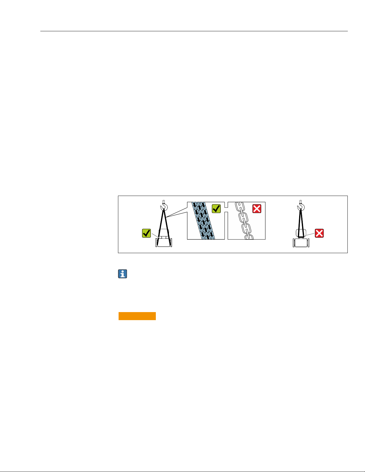
5.2.1 Measuring devices without lifting lugs
WARNING
L
Center of gravity of the measuring device is higher than the suspension points of the
webbing slings.
Risk of injury if the measuring device slips.
Secure the measuring device against slipping or turning.
‣
Observe the weight specified on the packaging (stick-on label).
‣
21
Page 22
Storage and transport Proline Promass F 300 EtherNet/IP
A0029214
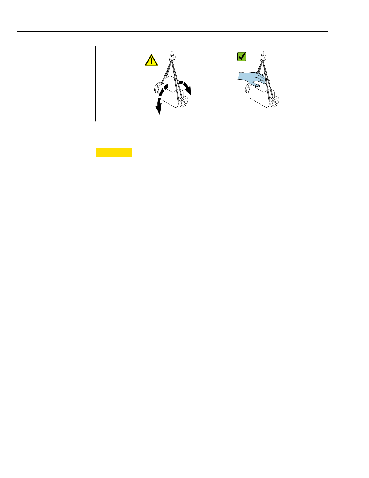
5.2.2 Measuring devices with lifting lugs
CAUTION
L
Special transportation instructions for devices with lifting lugs
Only use the lifting lugs fitted on the device or flanges to transport the device.
‣
The device must always be secured at two lifting lugs at least.
‣
5.2.3 Transporting with a fork lift
If transporting in wood crates, the floor structure enables the crates to be lifted lengthwise
or at both sides using a forklift.
5.3 Packaging disposal
All packaging materials are environmentally friendly and 100% recyclable:
• Measuring device secondary packaging: polymer stretch film that conforms to EC
Directive 2002/95/EC (RoHS).
• Packaging:
– Wood crate, treated in accordance with ISPM 15 standard, which is confirmed by the
affixed IPPC logo.
or
– Carton in accordance with European Packaging Directive 94/62EC; recyclability is
confirmed by the affixed RESY symbol.
• Seaworthy packaging (optional): Wood crate, treated in accordance with ISPM 15
standard, which is confirmed by the affixed IPPC logo.
• Carrying and mounting hardware:
– Disposable plastic pallet
– Plastic straps
– Plastic adhesive strips
• Dunnage: Paper cushion
22
Page 23
Proline Promass F 300 EtherNet/IP Installation
6 Installation
6.1 Installation conditions
No special measures such as supports are necessary. External forces are absorbed by the
construction of the device.
6.1.1 Mounting position
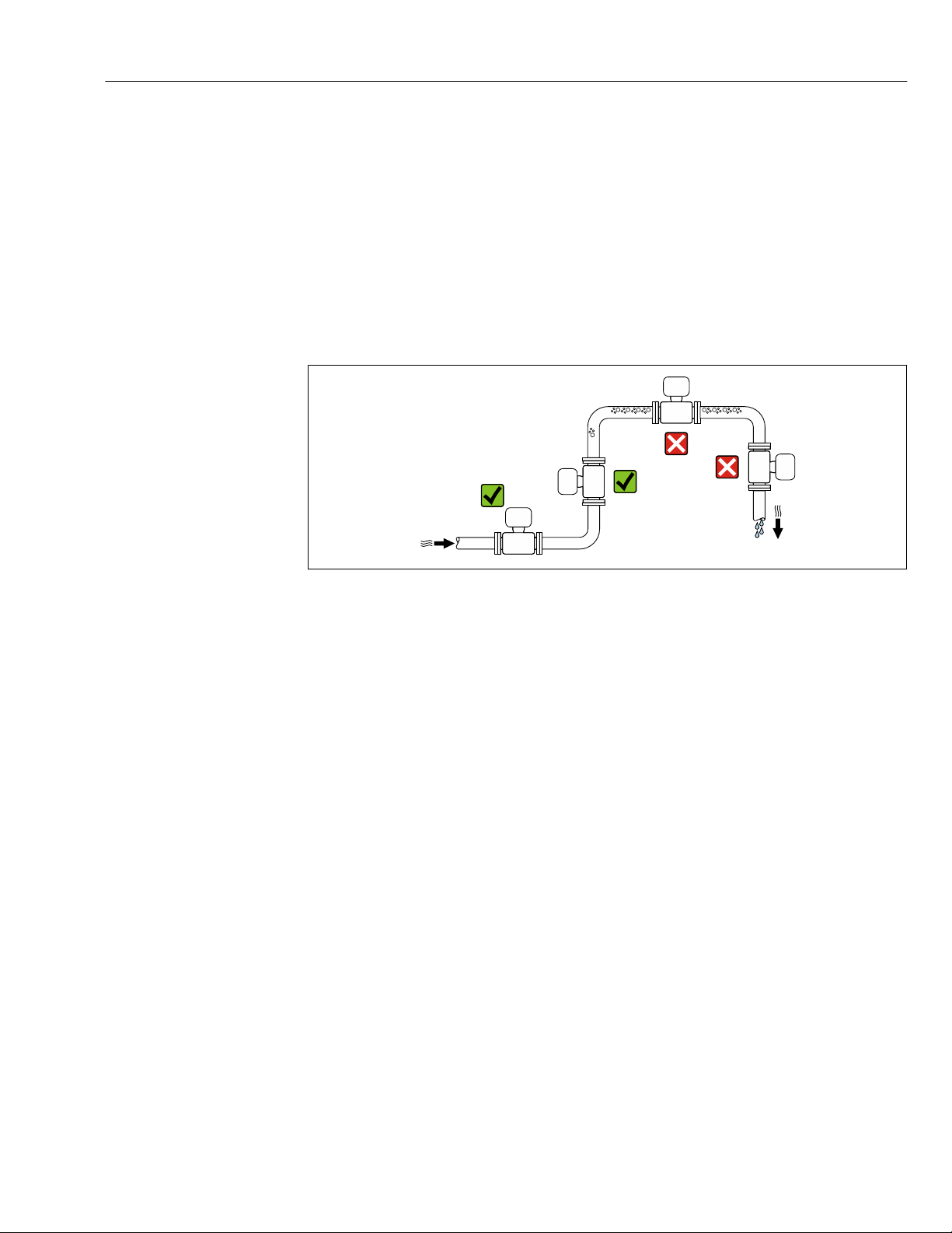
Mounting location
To prevent measuring errors arising from accumulation of gas bubbles in the measuring
tube, avoid the following mounting locations in the pipe:
• Highest point of a pipeline.
• Directly upstream of a free pipe outlet in a down pipe.
Installation in down pipes
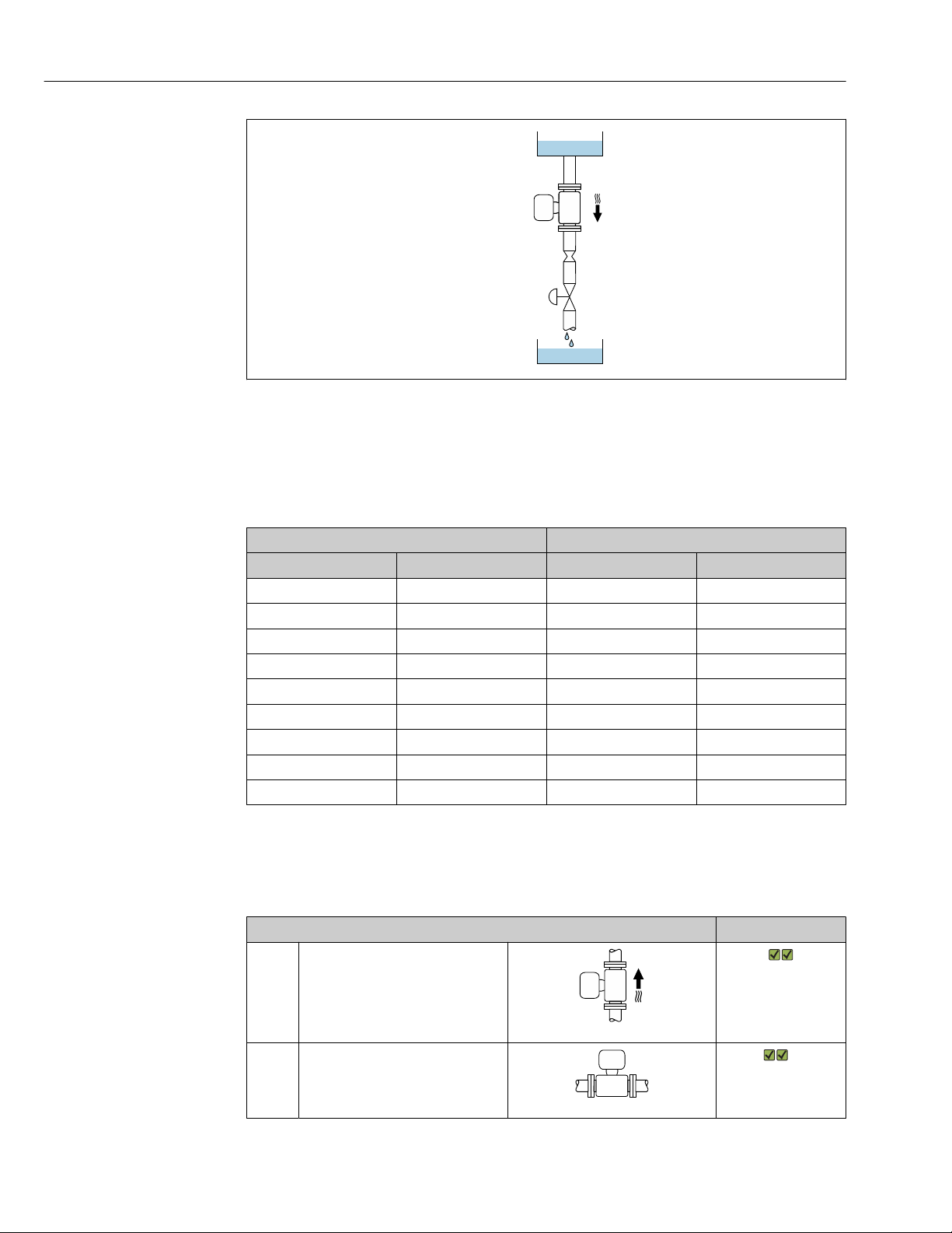
However, the following installation suggestion allows for installation in an open vertical
pipeline. Pipe restrictions or the use of an orifice with a smaller cross-section than the
nominal diameter prevent the sensor running empty while measurement is in progress.
A0028772
23
Page 24
Installation Proline Promass F 300 EtherNet/IP
1
2
3
4
5
A0028773
4 Installation in a down pipe (e.g. for batching applications)
1 Supply tank
2 Sensor
3 Orifice plate, pipe restriction
4 Valve
5 Batching tank
DN Ø orifice plate, pipe restriction
[mm] [in] [mm] [in]
8 ³⁄₈ 6 0.24
15 ½ 10 0.40
25 1 14 0.55
40 1½ 22 0.87
50 2 28 1.10
80 3 50 1.97
100 4 65 2.60
150 6 90 3.54
250 10 150 5.91
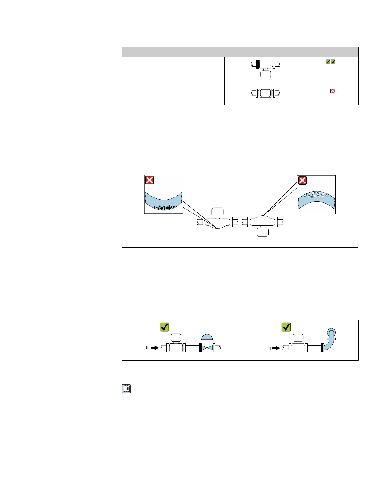
Orientation
The direction of the arrow on the sensor nameplate helps you to install the sensor
according to the flow direction (direction of medium flow through the piping).
Orientation Recommendation
A Vertical orientation
A0015591
B Horizontal orientation, transmitter at
top
A0015589
1)
Exceptions:
→ 5, 25
24
Page 25
Proline Promass F 300 EtherNet/IP Installation
1 2
Orientation Recommendation
C Horizontal orientation, transmitter at
bottom
A0015590
D Horizontal orientation, transmitter at
side
1) Applications with low process temperatures may decrease the ambient temperature. To maintain the
minimum ambient temperature for the transmitter, this orientation is recommended.
2) Applications with high process temperatures may increase the ambient temperature. To maintain the
maximum ambient temperature for the transmitter, this orientation is recommended.
A0015592
2)
Exceptions:
→ 5, 25
If a sensor is installed horizontally with a curved measuring tube, match the position of the
sensor to the fluid properties.
5 Orientation of sensor with curved measuring tube
1 Avoid this orientation for fluids with entrained solids: Risk of solids accumulating.
2 Avoid this orientation for outgassing fluids: Risk of gas accumulating.
Inlet and outlet runs
No special precautions need to be taken for fittings which create turbulence, such as
valves, elbows or T-pieces, as long as no cavitation occurs → 26.
A0029322 A0029323
Installation dimensions
For the dimensions and installation lengths of the device, see the "Technical
Information" document, "Mechanical construction" section.
A0028774
25
Page 26
Installation Proline Promass F 300 EtherNet/IP
6.1.2 Requirements from environment and process
Ambient temperature range
Measuring device • –40 to +60 °C (–40 to +140 °F)
• Order code for "Test, certificate", option JP:
–50 to +60 °C (–58 to +140 °F)
Readability of the local
display
Dependency of ambient temperature on medium temperature→ 238
If operating outdoors:
‣
Avoid direct sunlight, particularly in warm climatic regions.
You can order a weather protection cover from Endress+Hauser : → 219
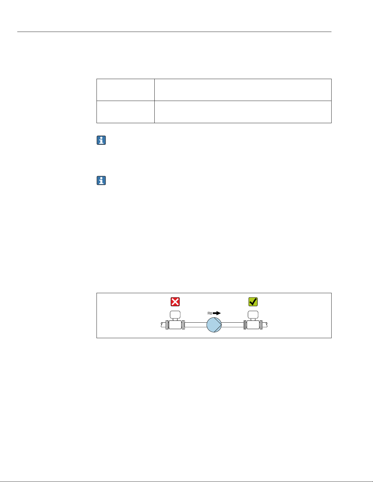
System pressure
It is important that cavitation does not occur, or that gases entrained in the liquids do not
outgas.
Cavitation is caused if the pressure drops below the vapor pressure:
• In liquids that have a low boiling point (e.g. hydrocarbons, solvents, liquefied gases)
• In suction lines
Ensure the system pressure is sufficiently high to prevent cavitation and outgassing.
‣
–20 to +60 °C (–4 to +140 °F)
The readability of the display may be impaired at temperatures outside the
temperature range.
For this reason, the following mounting locations are recommended:
• At the lowest point in a vertical pipe
• Downstream from pumps (no danger of vacuum)
A0028777
Thermal insulation
In the case of some fluids, it is important to keep the heat radiated from the sensor to the
transmitter to a low level. A wide range of materials can be used for the required
insulation.
26
Page 27
Proline Promass F 300 EtherNet/IP Installation
The following device versions are recommended for versions with thermal insulation:
• Version with extended neck for insulation:
Order code for "Sensor option", option CG with an extended neck length of
105 mm (4.13 in).
• Extended temperature version:
Order code for "Measuring tube material", option SD, SE, SF or TH with an extended neck
length of 105 mm (4.13 in).
• High-temperature version:
Order code for "Measuring tube material", option TT or TU with an extended neck length
of 142 mm (5.59 in).
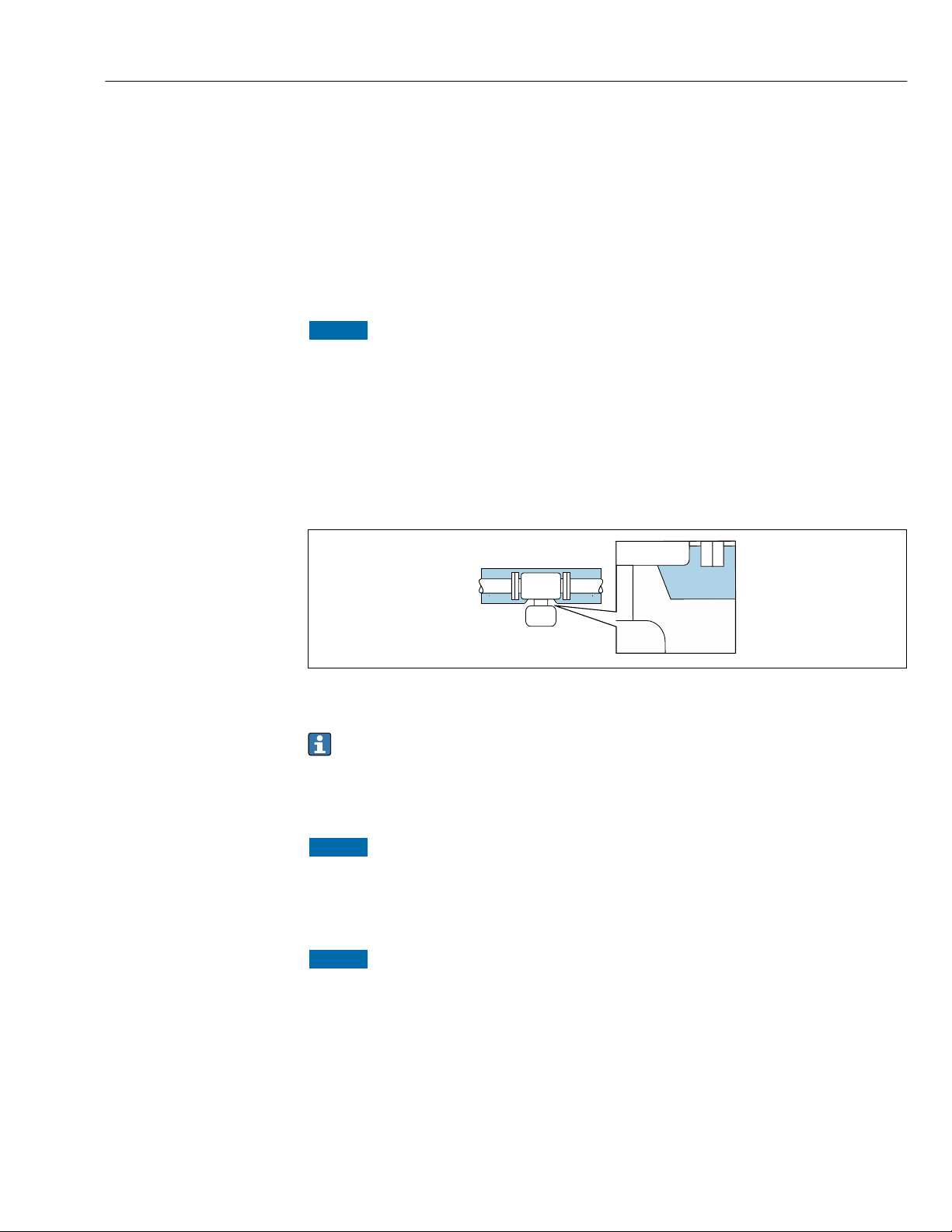
NOTICE
Electronics overheating on account of thermal insulation!
Recommended orientation: horizontal orientation, transmitter housing pointing
‣
downwards.
Do not insulate the transmitter housing .
‣
Maximum permissible temperature at the lower end of the transmitter housing:
‣
80 °C (176 °F)
Thermal insulation with extended neck free: the insulation is omitted around the
‣
extended neck. We recommend that you do not insulate the extended neck in order to
ensure optimum dissipation of heat.
6 Thermal insulation with extended neck free
Low-temperature version: It is generally not necessary to insulate the transmitter
housing . If insulation is provided, the rules that apply are the same as those for
thermal insulation.
Heating
NOTICE
Electronics can overheat due to elevated ambient temperature!
Observe maximum permitted ambient temperature for the transmitter .
‣
Depending on the fluid temperature, take the device orientation requirements into
‣
account .
NOTICE
Danger of overheating when heating
Ensure that the temperature at the lower end of the transmitter housing does not
‣
exceed 80 °C (176 °F).
Ensure that convection takes place on a sufficiently large scale at the transmitter neck.
‣
Ensure that a sufficiently large area of the housing support remains exposed. The
‣
uncovered part serves as a radiator and protects the electronics from overheating and
excessive cooling.
A0034391
27
Page 28
Installation Proline Promass F 300 EtherNet/IP
Heating options
If a fluid requires that no heat loss should occur at the sensor, users can avail of the
following heating options:
• Electrical heating, e.g. with electric band heaters
• Via pipes carrying hot water or steam
• Via heating jackets
Using an electrical trace heating system
If heating is regulated via phase angle control or pulse packages, magnetic fields can affect
the measured values (= for values that are greater than the values permitted by the EN
standard (sine 30 A/m)).
For this reason, the sensor must be magnetically shielded: the housing can be shielded
with tin plates or electric sheets without a privileged direction (e.g. V330-35A).
The sheet must have the following properties:
• Relative magnetic permeability µr ≥ 300
• Plate thickness d ≥ 0.35 mm (d ≥ 0.014 in)
Vibrations
The high oscillation frequency of the measuring tubes ensures that the correct operation of
the measuring system is not influenced by plant vibrations.
6.1.3 Special mounting instructions
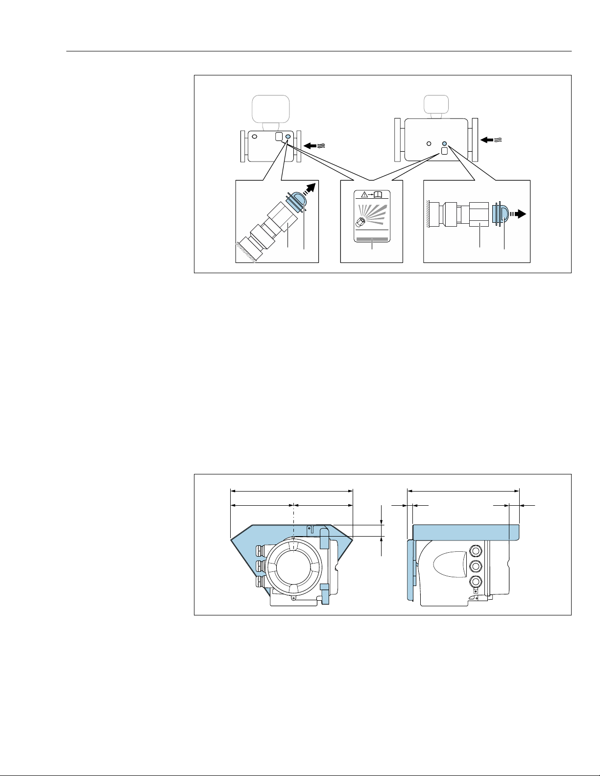
Rupture disk
Information that is relevant to the process: → 241.
WARNING
L
Limited functional reliability of the rupture disk.
Danger to persons from escaping fluids!
Do not remove the rupture disk.
‣
When using a rupture disk, do not use a heating jacket.
‣
Make sure that the function and operation of the rupture disk is not impeded through
‣
the installation of the device.
Take precautions to prevent damage and danger to persons if the rupture disk is
‣
actuated.
Observe information on the rupture disk sticker.
‣
The position of the rupture disk is indicated on a sticker beside it.
The transportation guard must be removed.
For information on the dimensions: see the "Mechanical construction" section
The existing connecting nozzles are not intended for the purpose of rinsing or pressure
monitoring, but instead serve as the mounting location for the rupture disk.
In the event of a failure of the rupture disk, a discharge device can be screwed onto the
internal thread of the rupture disk in order to drain off any escaping medium.
28
Page 29
Proline Promass F 300 EtherNet/IP Installation
RUPTURE DISK
i
2
3
1
DN 8 ( ")...150 (6")!⁄# DN 250 (10")
2
3
146 (5.75)
48 (1.9)
12 (0.47)
280 (11.0) 255 (10.0)
134 (5.3)
30 (1.18)
A0028903
1 Rupture disk label
2 Rupture disk with 1/2" NPT internal thread with 1" width across flat
3 Transport protection
Zero point adjustment
All measuring devices are calibrated in accordance with state-of-the-art technology.
Calibration takes place under reference conditions→ 232. Therefore, a zero point
adjustment in the field is generally not required.
Experience shows that zero point adjustment is advisable only in special cases:
• To achieve maximum measuring accuracy even with low flow rates.
• Under extreme process or operating conditions (e.g. very high process temperatures or
very high-viscosity fluids).
Protective cover
A0029553
29
Page 30
Installation Proline Promass F 300 EtherNet/IP
1
1
2
2
1
5 (0.2) min. 15 (0.6)
SW 2.5
M3
Cover locking
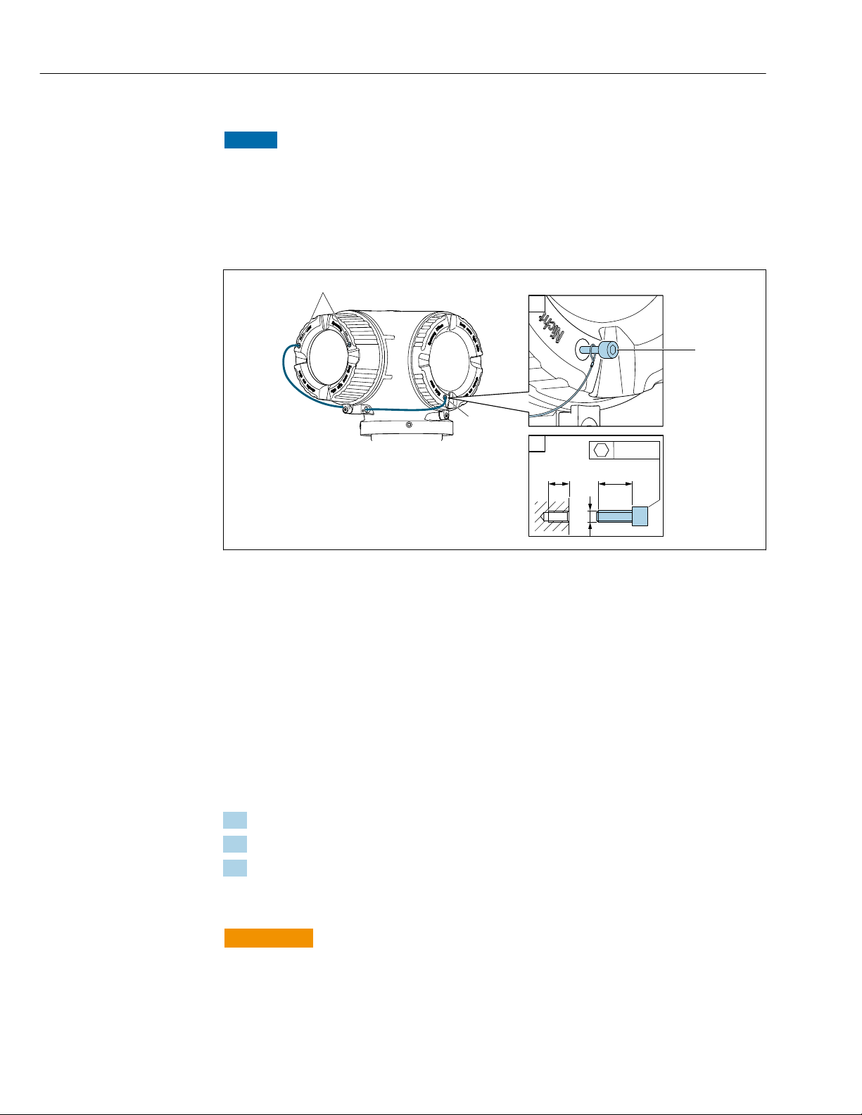
NOTICE
Order code "Housing", option L "Cast, stainless": The covers of the transmitter housing
are provided with a borehole to lock the cover.
The cover can be locked using screws and a chain or cable provided by the customer.
It is recommended to use stainless steel cables or chains.
‣
If a protective coating is applied, it is recommended to use a heat shrink tube to protect
‣
the housing paint.
30
1 Cover borehole for the securing screw
2 Securing screw to lock the cover
6.2 Mounting the measuring device
6.2.1 Required tools
For sensor
For flanges and other process connections: Corresponding mounting tools
6.2.2 Preparing the measuring device
1. Remove all remaining transport packaging.
2. Remove any protective covers or protective caps present from the sensor.
3. Remove stick-on label on the electronics compartment cover.
6.2.3 Mounting the measuring device
WARNING
L
Danger due to improper process sealing!
Ensure that the inside diameters of the gaskets are greater than or equal to that of the
‣
process connections and piping.
Ensure that the gaskets are clean and undamaged.
‣
Install the gaskets correctly.
‣
A0029800
Page 31
Proline Promass F 300 EtherNet/IP Installation
N
i
c
h
t
u
n
t
e
r
a
r
e
ö
f
f
n
e
n
+
E
ESC
–
1.
2.
N
i
c
h
t
u
n
t
e
r
a
r
e
ö
f
f
n
e
n
+
E
ESC
–
3.
3 mm 4 mm
4.
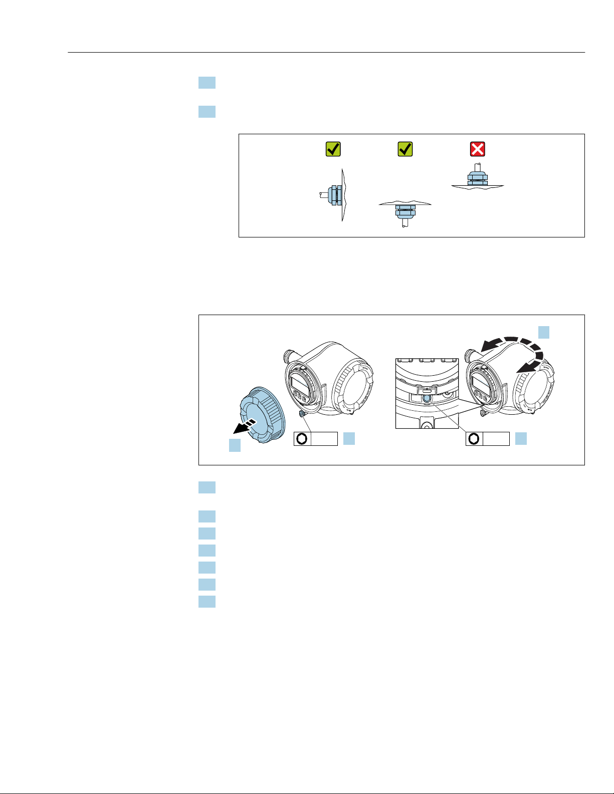
1. Ensure that the direction of the arrow on the nameplate of the sensor matches the
flow direction of the fluid.
2. Install the measuring device or turn the transmitter housing so that the cable entries
do not point upwards.
A0029263
6.2.4 Turning the transmitter housing
To provide easier access to the connection compartment or display module, the transmitter
housing can be turned.
A0029993
1. Depending on the device version: Loosen the securing clamp of the connection
compartment cover.
2. Unscrew the connection compartment cover.
3. Release the fixing screw.
4. Turn the housing to the desired position.
5. Firmly tighten the securing screw.
6. Screw on the connection compartment cover
7. Depending on the device version: Attach the securing clamp of the connection
compartment cover.
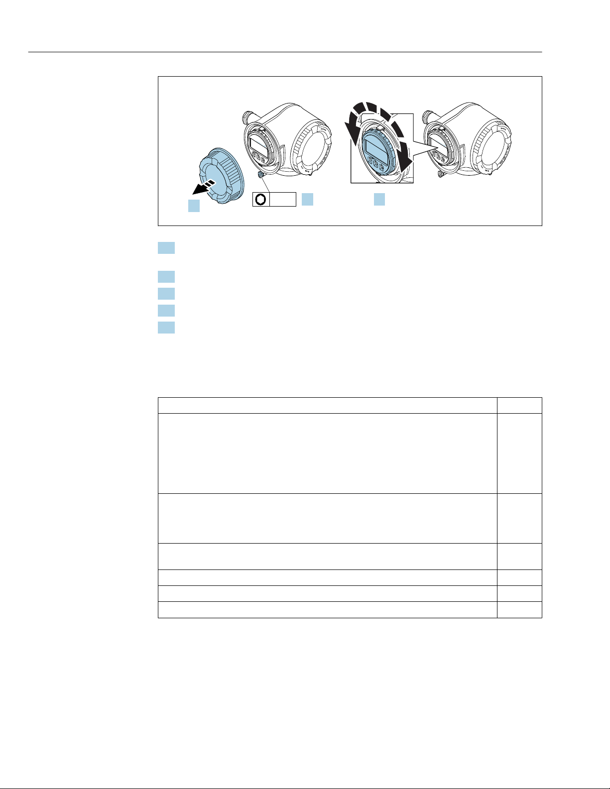
6.2.5 Turning the display module
The display module can be turned to optimize display readability and operability.
31
Page 32
Installation Proline Promass F 300 EtherNet/IP
N
i
c
h
t
u
n
t
e
r
a
r
e
ö
f
f
n
e
n
+
E
ESC
–
1.
2.
N
i
c
h
t
u
n
t
e
r
a
r
e
ö
f
f
n
e
n
+
E
ESC
–
3.
3 mm
+
E
ESC
–
A0030035
1. Depending on the device version: Loosen the securing clamp of the connection
compartment cover.
2. Unscrew the connection compartment cover.
3. Turn the display module to the desired position: max. 8 × 45° in each direction.
4. Screw on the connection compartment cover.
5. Depending on the device version: Attach the securing clamp of the connection
compartment cover.
6.3 Post-installation check
Is the device undamaged (visual inspection)?
Does the measuring device conform to the measuring point specifications?
For example:
• Process temperature → 238
• Process pressure (refer to the section on "Pressure-temperature ratings" in the "Technical
Information" document)
• Ambient temperature
• Measuring range
Has the correct orientation for the sensor been selected ?
• According to sensor type
• According to medium temperature
• According to medium properties (outgassing, with entrained solids)
Does the arrow on the sensor nameplate match the direction of flow of the fluid through the
piping → 24?
Are the measuring point identification and labeling correct (visual inspection)?
Is the device adequately protected from precipitation and direct sunlight?
Are the securing screw and securing clamp tightened securely?
32
Page 33

Proline Promass F 300 EtherNet/IP Electrical connection
7 Electrical connection
NOTICE
The measuring device does not have an internal circuit breaker.
For this reason, assign the measuring device a switch or power-circuit breaker so that
‣
the power supply line can be easily disconnected from the mains.
Although the measuring device is equipped with a fuse, additional overcurrent
‣
protection (maximum 10 A) should be integrated into the system installation.
7.1 Connection conditions
7.1.1 Required tools
• For cable entries: Use corresponding tools
• For securing clamp: Allen key 3 mm
• Wire stripper
• When using stranded cables: Crimper for wire end ferrule
• For removing cables from terminal: Flat blade screwdriver ≤ 3 mm (0.12 in)
7.1.2 Requirements for connecting cable
The connecting cables provided by the customer must fulfill the following requirements.
Electrical safety
In accordance with applicable federal/national regulations.
Protective ground cable
Cable: 2.1 mm2 (14 AWG)
The grounding impedance must be less than 1 Ω.
Permitted temperature range
• The installation guidelines that apply in the country of installation must be observed.
• The cables must be suitable for the minimum and maximum temperatures to be
expected.
Power supply cable
Standard installation cable is sufficient.
Signal cable
EtherNet/IP
The standard ANSI/TIA/EIA-568-B.2 Annex specifies CAT 5 as the minimum category for
a cable used for EtherNet/IP. CAT 5e and CAT 6 are recommended.
For more information on planning and installing EtherNet/IP networks, please refer
to the "Media Planning and Installation Manual. EtherNet/IP" of ODVA Organization
Current output 0/4 to 20 mA
Standard installation cable is sufficient.
33
Page 34

Electrical connection Proline Promass F 300 EtherNet/IP
Pulse/frequency/switch output
Standard installation cable is sufficient.
Relay output
Standard installation cable is sufficient.
Current input 0/4 to 20 mA
Standard installation cable is sufficient.
Status input
Standard installation cable is sufficient.
Cable diameter
• Cable glands supplied:
M20 × 1.5 with cable ⌀ 6 to 12 mm (0.24 to 0.47 in)
• Spring-loaded terminals: Suitable for strands and strands with ferrules.
Conductor cross-section 0.2 to 2.5 mm2 (24 to 12 AWG).
Requirements for the connecting cable
Optionally available connecting cable
A cable is supplied depending on the order option
• Order code for measuring device: order code 030 for "Display; operation", option O
or
• Order code for measuring device: order code 030 for "Display; operation", option M
and
• Order code for DKX001: order code 040 for "Cable", option A, B, D, E
Standard cable
Flame resistance According to DIN EN 60332-1-2
Oil-resistance According to DIN EN 60811-2-1
Shielding Tin-plated copper-braid, optical cover ≥ 85 %
Capacitance: core/shield ≤200 pF/m
L/R ≤24 µH/Ω
Available cable length 5 m (15 ft)/10 m (35 ft)/20 m (65 ft)/30 m (100 ft)
Operating temperature When mounted in a fixed position: –50 to +105 °C (–58 to +221 °F); when cable
2 × 2 × 0.34 mm2 (22 AWG) PVC cable with common shield (2 pairs, pairstranded)
can move freely: –25 to +105 °C (–13 to +221 °F)
Standard cable - customer-specific cable
No cable is supplied, and it must be provided by the customer (up to max.
300 m (1 000 ft)) for the following order option:
Order code for DKX001: Order code 040 for "Cable", option 1 "None, provided by customer,
max 300 m"
A standard cable can be used as the connecting cable.
34
Standard cable 4 cores (2 pairs); pair-stranded with common shield
Shielding Tin-plated copper-braid, optical cover ≥ 85 %
Page 35
Proline Promass F 300 EtherNet/IP Electrical connection
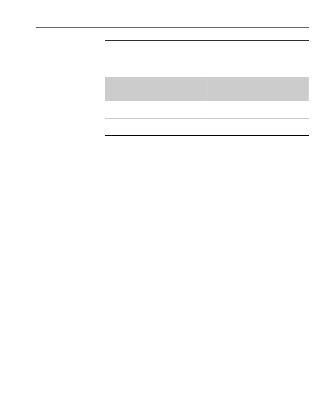
Capacitance: core/shield Maximum 1 000 nF for Zone 1, Class I, Division 1
L/R Maximum 24 µH/Ω for Zone 1, Class I, Division 1
Cable length Maximum 300 m (1 000 ft), see the following table
Max. cable length for use in
Cross-section
0.34 mm2 (22 AWG) 80 m (270 ft)
0.50 mm2 (20 AWG) 120 m (400 ft)
0.75 mm2 (18 AWG) 180 m (600 ft)
1.00 mm2 (17 AWG) 240 m (800 ft)
1.50 mm2 (15 AWG) 300 m (1 000 ft)
Non-hazardous area,
Ex Zone 2, Class I, Division 2
Ex Zone 1, Class I, Division 1
35
Page 36
Electrical connection Proline Promass F 300 EtherNet/IP
3
2
4
1
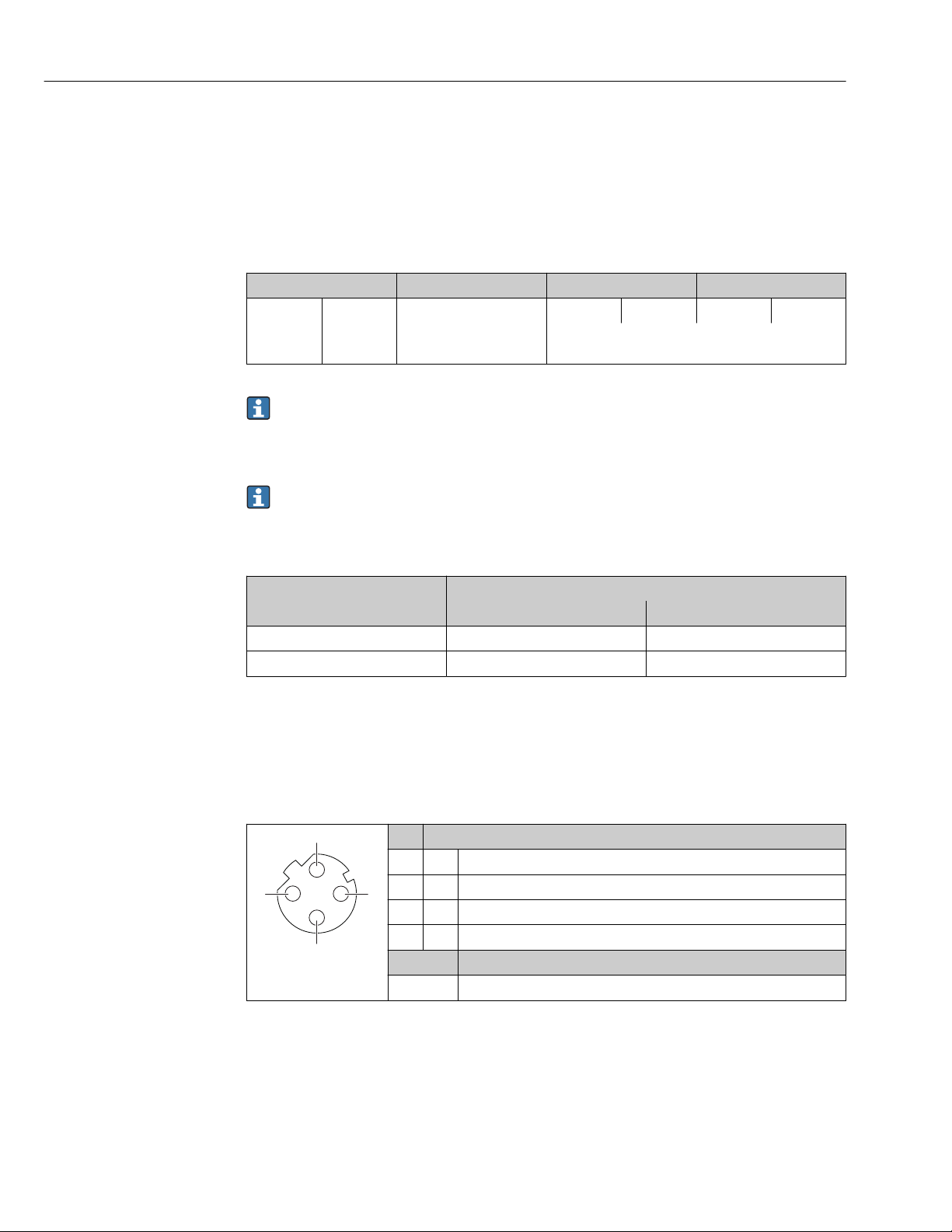
7.1.3 Terminal assignment
Transmitter: supply voltage, input/outputs
The terminal assignment of the inputs and outputs depends on the individual order
version of the device. The device-specific terminal assignment is documented on an
adhesive label in the terminal cover.
Supply voltage Input/output 1 Input/output 2 Input/output 3
1 (+) 2 (–) EtherNet/IP
(RJ45 connector)
24 (+) 25 (–) 22 (+) 23 (–)
Device-specific terminal assignment: adhesive label in
terminal cover.
Terminal assignment of the remote display and operating module → 43.
7.1.4 Device plugs available
Device plugs may not be used in hazardous areas!
Order code for "Input; output 1", option NA "EtherNet/IP"
Order code for Cable entry/connection
"Electrical connection" 2 3
L, N, P, U Connector M12 × 1 –
1) 2)
1) 2)
1) 2)
R
, S
, T
1) Cannot be combined with an external WLAN antenna (order code for "Enclosed accessories", option P8) of
an RJ45 M12 adapter for the service interface (order code for "Accessories mounted", option NB) or of the
remote display and operating module DKX001
2) Suitable for integrating the device in a ring topology.
, V
1) 2)
Connector M12 × 1 Connector M12 × 1
7.1.5 Pin assignment of device plug
Pin Assignment
1 + Tx
2 + Rx
3 - Tx
4 - Rx
A0016812
Coding Plug/socket
D Socket
36
Page 37
Proline Promass F 300 EtherNet/IP Electrical connection
1
2
3
4
7.1.6 Preparing the measuring device
NOTICE
Insufficient sealing of the housing!
Operational reliability of the measuring device could be compromised.
Use suitable cable glands corresponding to the degree of protection.
‣
1. Remove dummy plug if present.
2. If the measuring device is supplied without cable glands:
Provide suitable cable gland for corresponding connecting cable.
3. If the measuring device is supplied with cable glands:
Observe requirements for connecting cables → 33.
7.2 Connecting the measuring device
NOTICE
Limitation of electrical safety due to incorrect connection!
Have electrical connection work carried out by appropriately trained specialists only.
‣
Observe applicable federal/national installation codes and regulations.
‣
Comply with local workplace safety regulations.
‣
Always connect the protective ground cable before connecting additional cables.
‣
For use in potentially explosive atmospheres, observe the information in the device-
‣
specific Ex documentation.
7.2.1 Connecting the transmitter
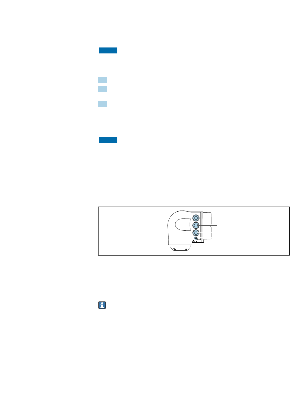
A0026781
1 Terminal connection for supply voltage
2 Terminal connection for signal transmission, input/output
3 Terminal connection for signal transmission, input/output or terminal connection for network connection via
service interface (CDI-RJ45); optional: connection for external WLAN antenna or remote display and
operating module DKX001
4 Protective earth (PE)
In addition to connecting the device via EtherNet/IP and the available inputs/outputs,
additional connection options are also available:
• Integrate into a network via the service interface (CDI-RJ45) → 41.
• Integrate the device into a ring topology → 42.
37
Page 38
Electrical connection Proline Promass F 300 EtherNet/IP
N
i
c
h
t
u
n
t
e
r
a
r
e
ö
f
f
n
e
n
+
E
ESC
–
1.
2.
N
i
c
h
t
u
n
t
e
r
a
r
e
ö
f
f
n
e
n
+
E
ESC
–
+
E
ESC
–
3.
3.
4.
3 mm
N
i
c
h
t
u
n
t
e
r
a
r
e
ö
f
f
n
e
n
Nicht unter
Spannung öffnen
Do not open when
energized
Ne pas ouvrir
sous tension
Power
I/O
+
E
ESC
–
5.
N
i
c
h
t
u
n
t
e
r
a
r
e
ö
f
f
n
e
n
Nicht unter
Spannung öffnen
Do not open when
energized
Ne pas ouvrir
sous tension
Power
I/O
+
E
ESC
–
Power
Nicht unter
Spannung öffnen
Do not open when
energized
Ne pas ouvrir
sous tension
I/O
6.
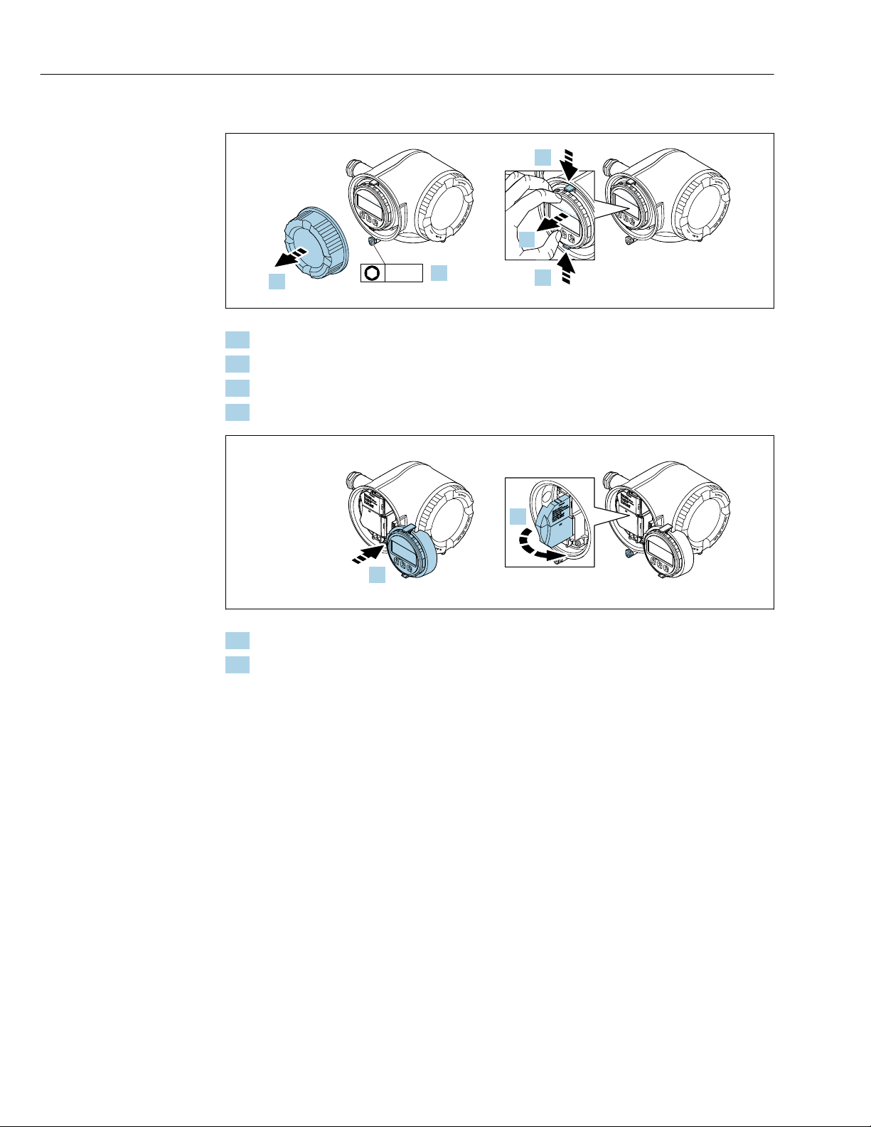
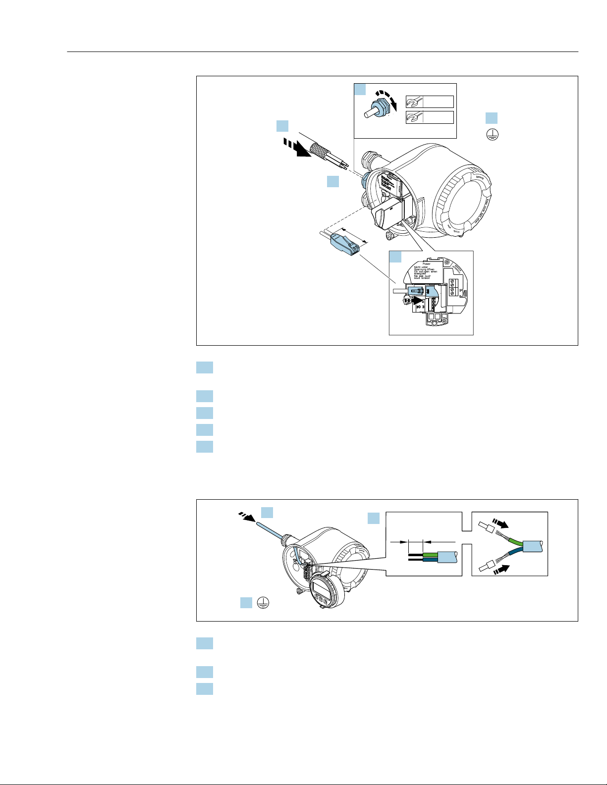
Connecting the EtherNet/IP connector
A0029813
1. Loosen the securing clamp of the connection compartment cover.
2. Unscrew the connection compartment cover.
3. Squeeze the tabs of the display module holder together.
4. Remove the display module holder.
A0029814
5. Attach the holder to the edge of the electronics compartment.
6. Open the terminal cover.
38
Page 39
Proline Promass F 300 EtherNet/IP Electrical connection
N
i
c
h
t
u
n
t
e
r
a
r
e
ö
f
f
n
e
n
Nicht unter
Spannung öffnen
Do not open when
energized
Ne pas ouvrir
sous tension
Power
7.
10.
22 mm
24 mm
8.
9.
11.
≤
42 (1.6)
N
i
c
h
t
u
n
t
e
r
a
r
e
ö
f
f
n
e
n
+
E
ESC
–
10 (0.4)
mm (in)
2.
1.
3.
A0033722
7. Push the cable through the cable entry . To ensure tight sealing, do not remove the
sealing ring from the cable entry.
8. Strip the cable and cable ends and connect to the RJ45 connector.
9. Connect the protective ground.
10. Plug in the RJ45 connector.
11. Firmly tighten the cable glands.
This concludes the EtherNet/IP connection process.
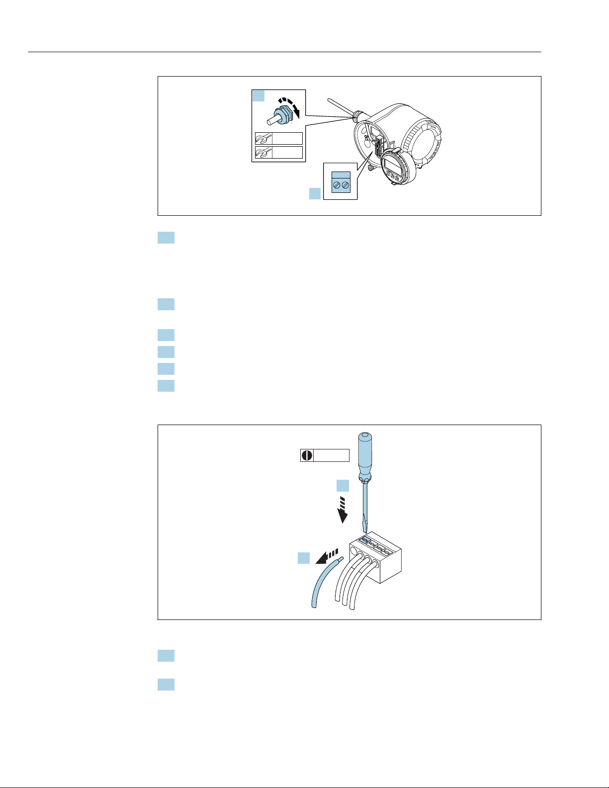
Connecting the supply voltage and additional inputs/outputs
A0033983
1. Push the cable through the cable entry . To ensure tight sealing, do not remove the
sealing ring from the cable entry.
2. Strip the cable and cable ends. In the case of stranded cables, also fit ferrules.
3. Connect the protective ground.
39
Page 40
Electrical connection Proline Promass F 300 EtherNet/IP
N
i
c
h
t
u
n
t
e
r
a
r
e
ö
f
f
n
e
n
+
E
ESC
–
22 mm
24 mm
5.
4.
3 (0.12)
2.
1.
A0033984
4. Connect the cable in accordance with the terminal assignment .
Signal cable terminal assignment: The device-specific terminal assignment is
documented on an adhesive label in the terminal cover.
Supply voltage terminal assignment: Adhesive label in the terminal cover or
→ 36.
5. Firmly tighten the cable glands.
This concludes the cable connection process.
6. Close the terminal cover.
7. Fit the display module holder in the electronics compartment.
8. Screw on the connection compartment cover.
9. Secure the securing clamp of the connection compartment cover.
Removing a cable
A0029598
7 Engineering unit mm (in)
1. To remove a cable from the terminal, use a flat-blade screwdriver to push the slot
between the two terminal holes
2. while simultaneously pulling the cable end out of the terminal.
40
Page 41
Proline Promass F 300 EtherNet/IP Electrical connection
N
i
c
h
t
u
n
t
e
r
a
r
e
ö
f
f
n
e
n
Nicht unter
Spannung öffnen
Do not open when
energized
Ne pas ouvrir
sous tension
Power
I/O
≤
42 (1.6)
1
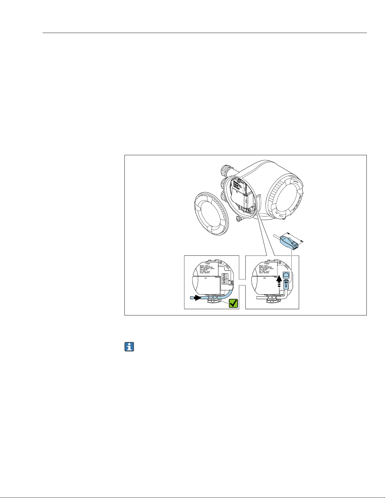
7.2.2 Integrating the transmitter into a network
This section only presents the basic options for integrating the device into a network.
For information on the procedure to follow to connect the transmitter correctly → 37.
Integrating via the service interface
The device is integrated via the connection to the service interface (CDI-RJ45).
Note the following when connecting:
• Recommended cable: CAT 5e, CAT 6 or CAT 7, with shielded connector
• Maximum cable thickness: 6 mm
• Length of connector including bend protection: 42 mm
• Bending radius: 5 x cable thickness
A0033703
1 Service interface (CDI-RJ45)
An adapter for RJ45 and the M12 connector is optionally available:
Order code for "Accessories", option NB: "Adapter RJ45 M12 (service interface)"
The adapter connects the service interface (CDI-RJ45) to an M12 connector mounted
in the cable entry. Therefore the connection to the service interface can be established
via an M12 connector without opening the device.
41
Page 42
Electrical connection Proline Promass F 300 EtherNet/IP
N
i
c
h
t
u
n
t
e
r
a
r
e
ö
f
f
n
e
n
Nicht unter
Spannung öffnen
Do not open when
energized
Ne pas ouvrir
sous tension
Power
≤
42 (1.6)
1
2
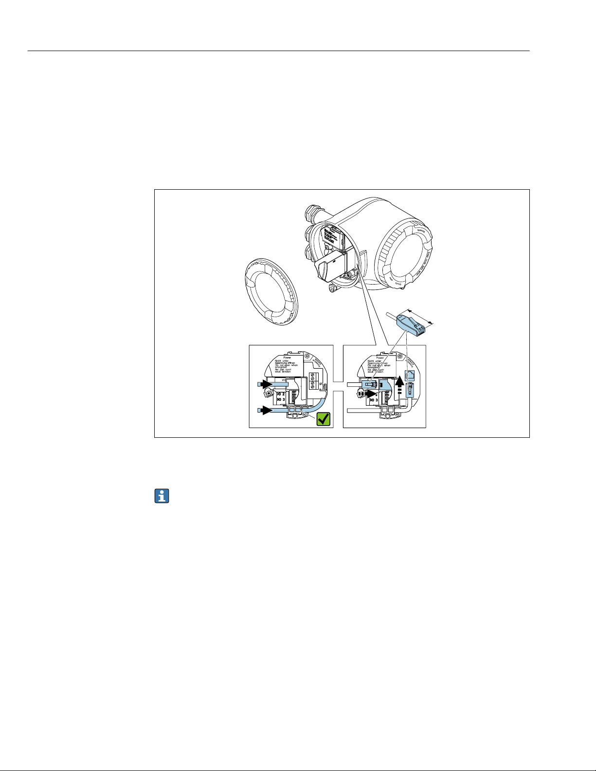
Integrating into a ring topology
The device is integrated via the terminal connection for signal transmission (output 1) and
the connection to the service interface (CDI-RJ45).
Note the following when connecting:
• Recommended cable: CAT5e, CAT6 or CAT7, with shielded connector
• Maximum cable thickness: 6 mm
• Length of connector including bend protection: 42 mm
• Bending radius: 2.5 x cable thickness
1 EtherNet/IP connection
2 Service interface (CDI-RJ45)
An adapter for RJ45 and the M12 connector is optionally available:
Order code for "Accessories", option NB: "Adapter RJ45 M12 (service interface)"
The adapter connects the service interface (CDI-RJ45) to an M12 connector mounted
in the cable entry. Therefore the connection to the service interface can be established
via an M12 connector without opening the device.
A0033717
42
Page 43
Proline Promass F 300 EtherNet/IP Electrical connection
1
3
81
Vcc
82
Gnd
83A84
B
81
Vcc
82
Gnd
83A84
B
2
4
5
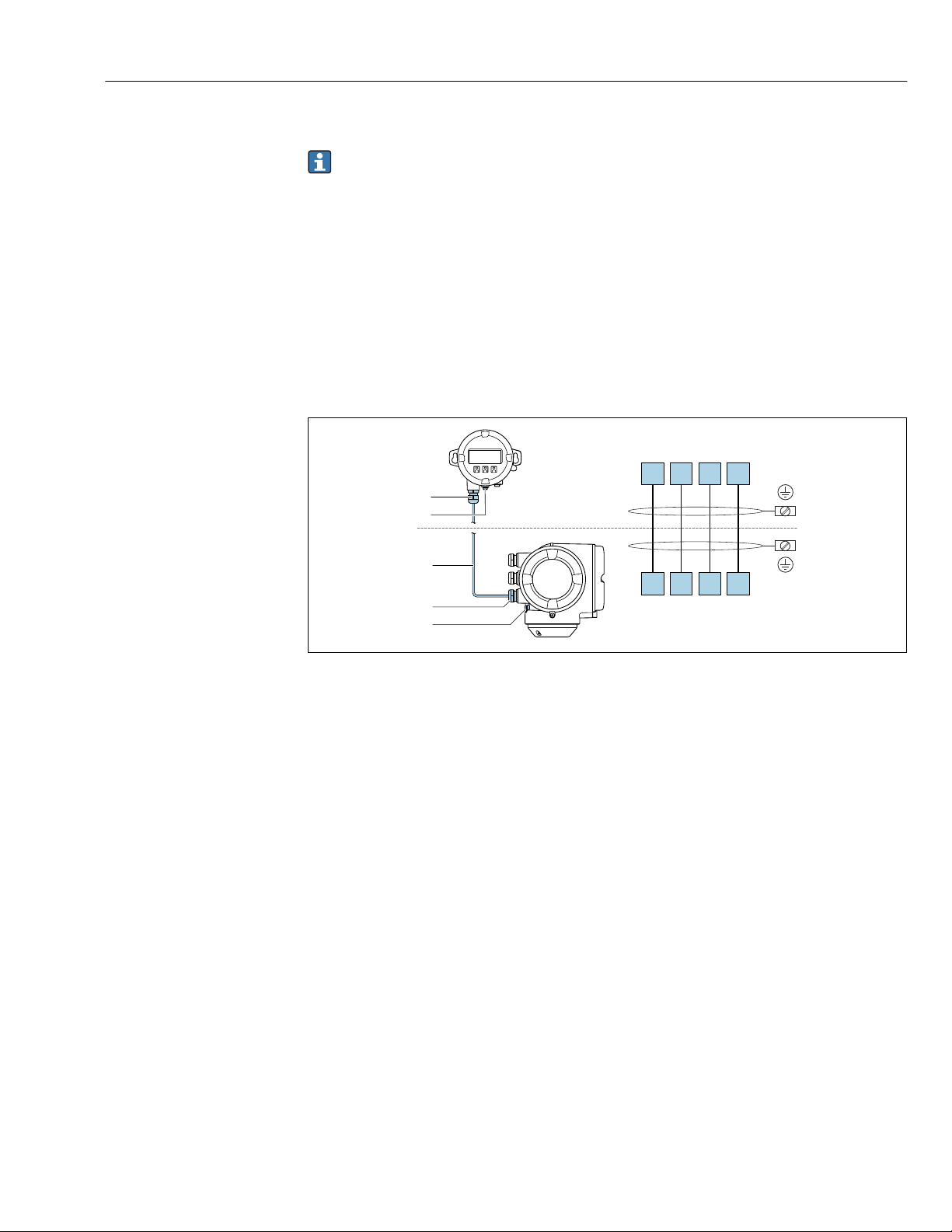
7.2.3 Connecting the remote display and operating module DKX001
The remote display and operating module DKX001 is available as an optional extra
→ 219.
• The remote display and operating module DKX001 is only available for the
following housing versions, order code for "Housing":
– Option A "Aluminum, coated"
– Option L "Cast, stainless"
• The measuring device is always supplied with a dummy cover when the remote
display and operating module DKX001 is ordered directly with the measuring
device. Display or operation at the transmitter is not possible in this case.
• If ordered subsequently, the remote display and operating module DKX001 may not
be connected at the same time as the existing measuring device display module.
Only one display or operation unit may be connected to the transmitter at any one
time.
A0027518
1 Remote display and operating module DKX001
2 Protective earth (PE)
3 Connecting cable
4 Measuring device
5 Protective earth (PE)
7.3 Ensure potential equalization
7.3.1 Requirements
No special measures for potential equalization are required.
43
Page 44
Electrical connection Proline Promass F 300 EtherNet/IP
1
2
4
3
5
5
1 2 4
5
5
3
7.4 Special connection instructions
7.4.1 Connection examples
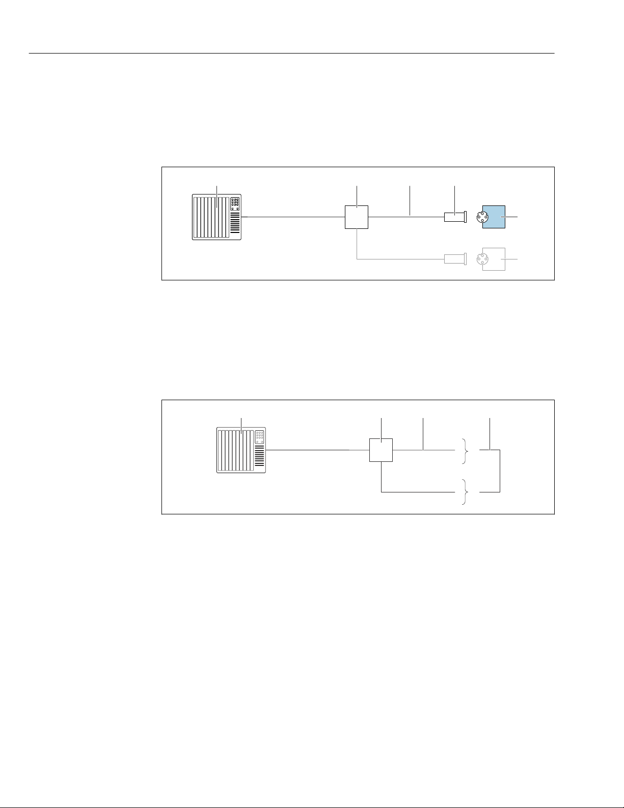
EtherNet/IP
A0028767
8 Connection example for EtherNet/IP
1 Control system (e.g. PLC)
2 Ethernet switch
3 Observe cable specifications
4 Device plug
5 Transmitter
EtherNet/IP: DLR (Device Level Ring)
1 Control system (e.g. PLC)
2 Ethernet switch
3 Observe cable specifications → 33
4 Connecting cable between the two transmitters
5 Transmitter
A0027544
44
Page 45
Proline Promass F 300 EtherNet/IP Electrical connection
4...20 mA
2
1
3
2
4...20 mA
3
1
4
1
2
3
12345
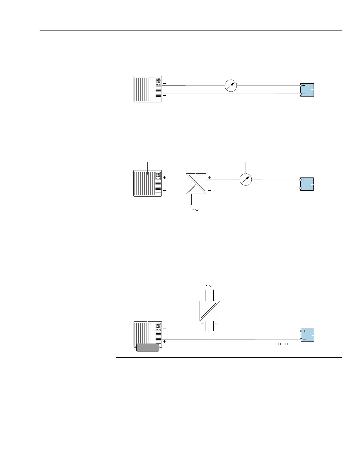
Current output 4-20 mA
A0028758
9 Connection example for 4-20 mA current output (active)
1 Automation system with current input (e.g. PLC)
2 Analog display unit: observe maximum load
3 Transmitter
10 Connection example for 4-20 mA current output (passive)
1 Automation system with current input (e.g. PLC)
2 Active barrier for power supply (e.g. RN221N)
3 Analog display unit: observe maximum load
4 Transmitter
Pulse/frequency output
11 Connection example for pulse/frequency output (passive)
1 Automation system with pulse/frequency input (e.g. PLC)
2 Power supply
3 Transmitter: Observe input values → 226
A0028759
A0028761
45
Page 46
Electrical connection Proline Promass F 300 EtherNet/IP
1
2
3
1
2
3
31
4
2
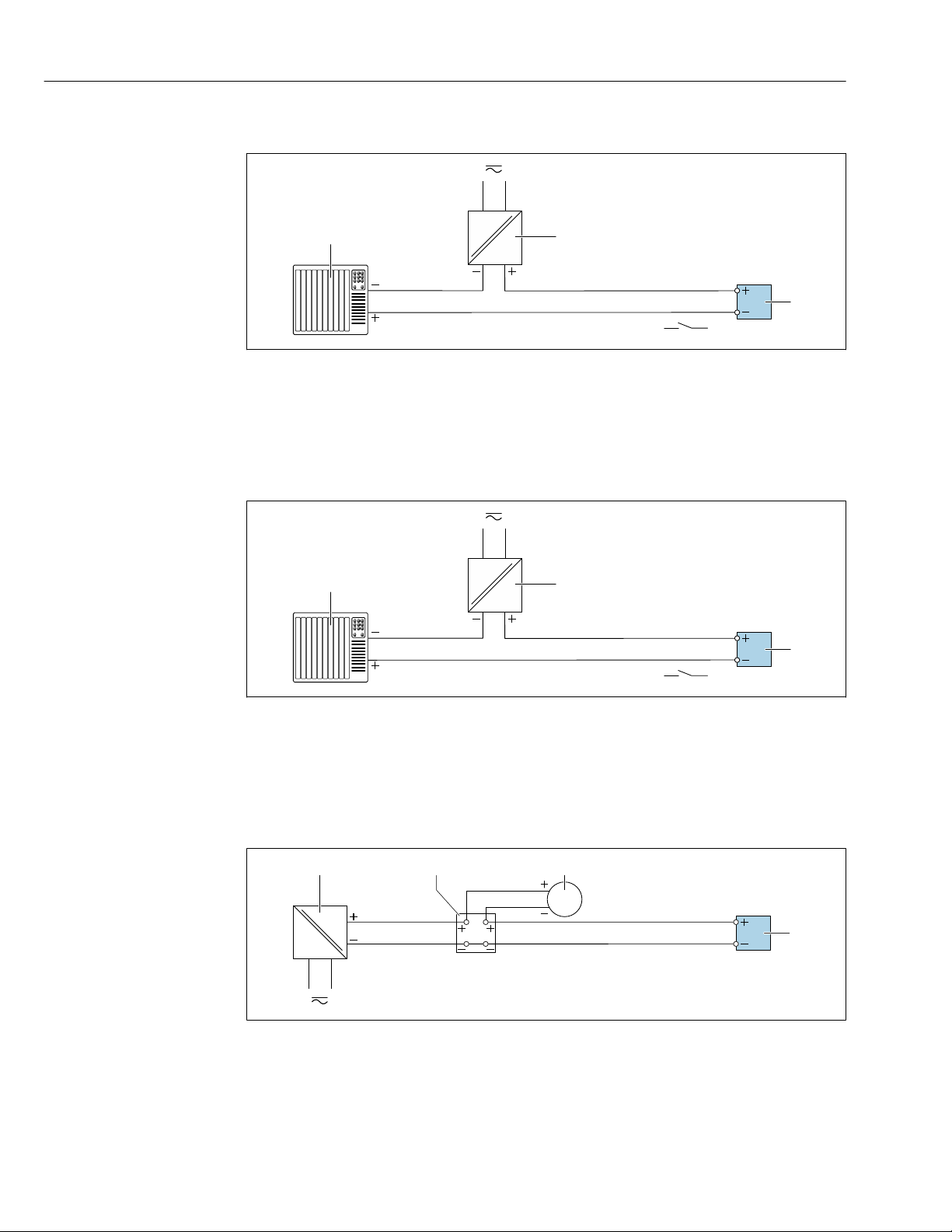
Switch output
A0028760
12 Connection example for switch output (passive)
1 Automation system with switch input (e.g. PLC)
2 Power supply
3 Transmitter: Observe input values → 226
Relay output
A0028760
13 Connection example for relay output (passive)
1 Automation system with relay input (e.g. PLC)
2 Power supply
3 Transmitter: Observe input values → 228
Current input
A0028915
14 Connection example for 4 to 20 mA current input
1 Power supply
2 External measuring device (for reading in pressure or temperature, for instance)
3 Transmitter: Observe input values
46
Page 47
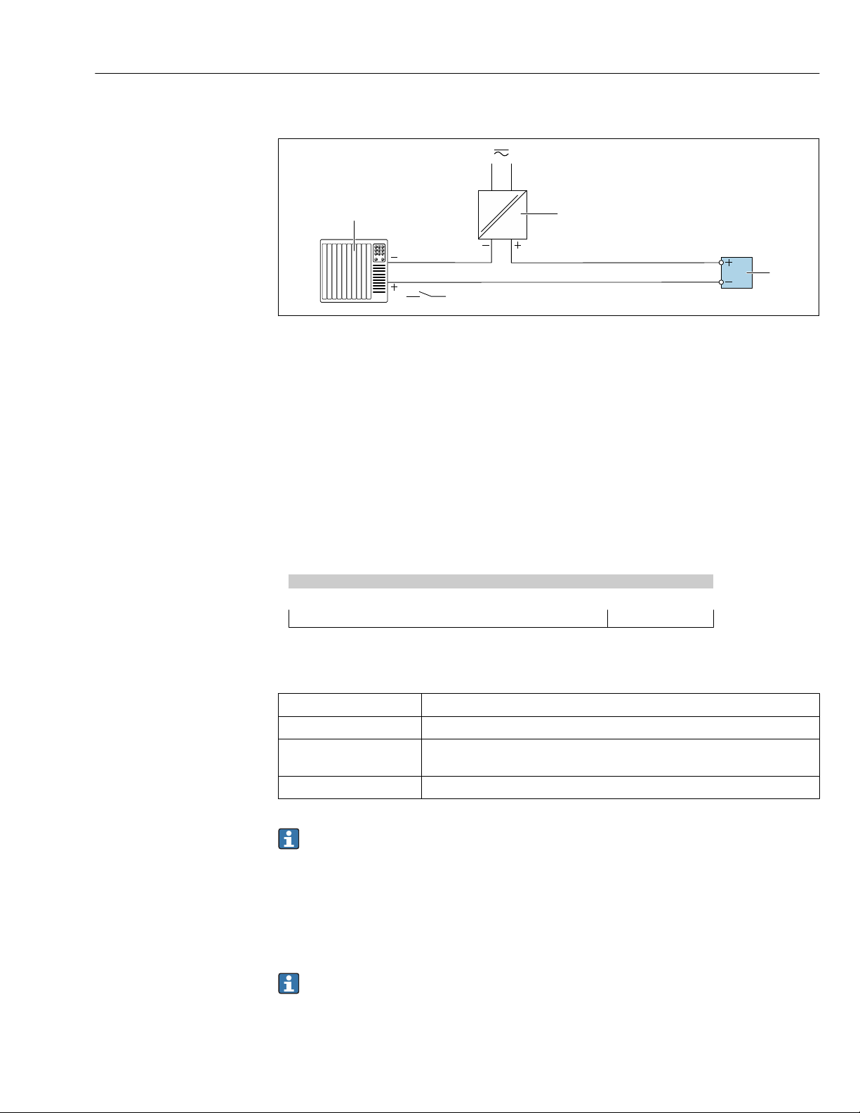
Proline Promass F 300 EtherNet/IP Electrical connection
1
2
3
Status input
A0028764
15 Connection example for status input
1 Automation system with status output (e.g. PLC)
2 Power supply
3 Transmitter: Observe input values
7.5 Hardware settings
7.5.1 Setting the device address
The IP address of the measuring device can be configured for the network via DIP switches.
Addressing data
IP address and configuration options
1st octet 2nd octet 3rd octet 4th octet
192. 168. 1. XXX
↓ ↓
Can only be configured via software addressing Can be configured via software addressing
and hardware addressing
IP address range 1 to 254 (4th octet)
IP address broadcast 255
Addressing mode ex
works
IP address ex works DHCP server active
Software addressing: The IP address is entered via the IP address parameter
(→ 104) .
Setting the IP address
Risk of electric shock when opening the transmitter housing.
Before opening the transmitter housing:
‣
Disconnect the device from the power supply.
‣
Software addressing; all DIP switches for hardware addressing are set to OFF.
The default IP address may not be activated → 48.
47
Page 48
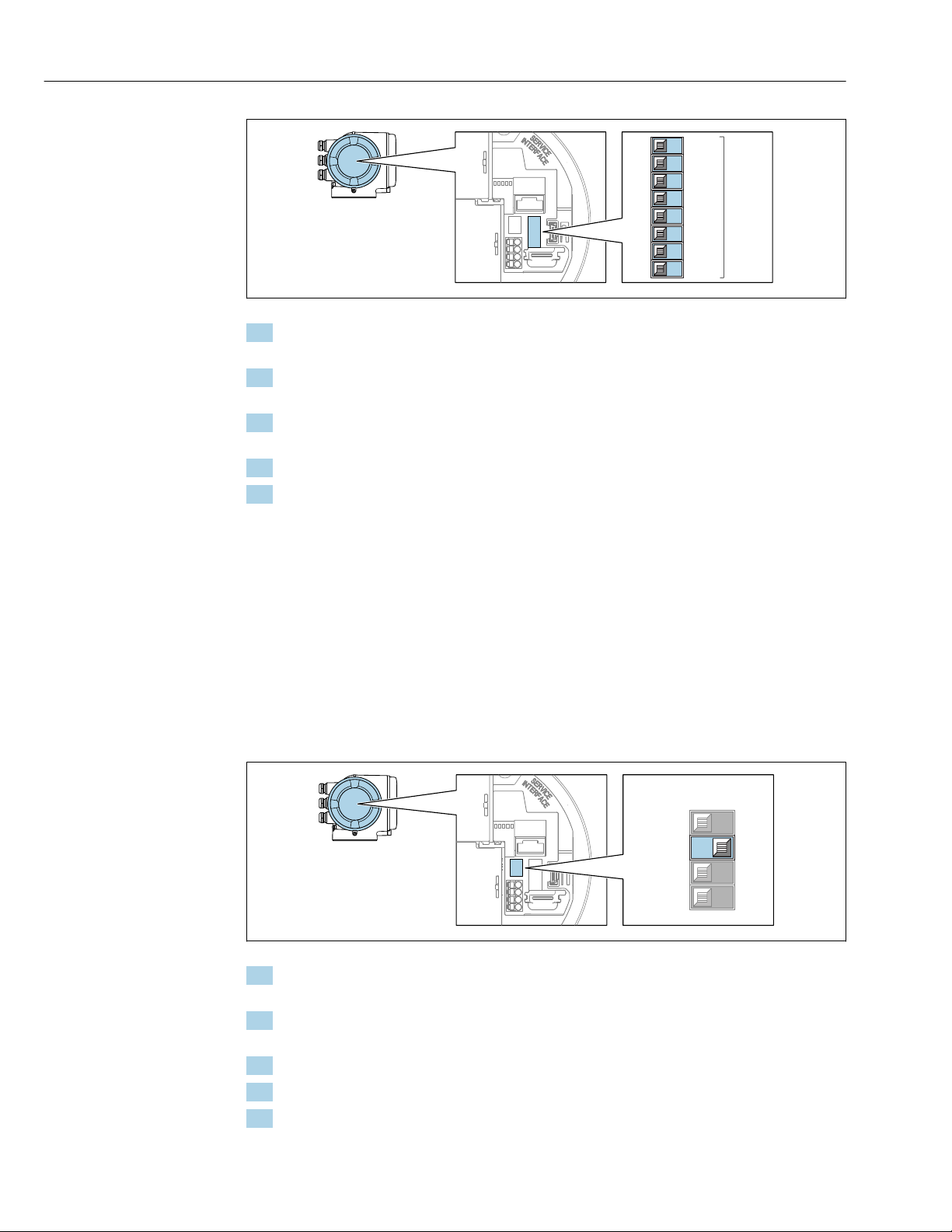
Electrical connection Proline Promass F 300 EtherNet/IP
1
2
3
4
5
6
7
8
128
64
32
16
8
4
2
1
IP Address setting
(last octet)
On
Off
4
3
1
2
A0029635
1. Depending on the housing version, loosen the securing clamp or fixing screw of the
housing cover.
2. Depending on the housing version, unscrew or open the housing cover and
disconnect the local display from the main electronics module where necessary.
3. Set the desired IP address using the corresponding DIP switches on the I/O
electronics module.
4. Reverse the removal procedure to reassemble the transmitter.
5. Reconnect the device to the power supply.
The configured device address is used once the device is restarted.
48
7.5.2 Activating the default IP address
The DHCP function is enabled in the device at the factory, i.e. the device expects an IP
address to be assigned by the network. This function can be disabled and the device can be
set to the default IP address 192.168.1.212 by DIP switch.
Activating the default IP address via the DIP switch
Risk of electric shock when opening the transmitter housing.
Before opening the transmitter housing:
‣
Disconnect the device from the power supply.
‣
A0034499
1. Depending on the housing version, loosen the securing clamp or fixing screw of the
housing cover.
2. Depending on the housing version, unscrew or open the housing cover and
disconnect the local display from the main electronics module where necessary .
3. Set DIP switch No. 2 on the I/O electronics module from OFF → ON.
4. Reverse the removal procedure to reassemble the transmitter.
5. Reconnect the device to the power supply.
The default IP address is used once the device is restarted.
Page 49
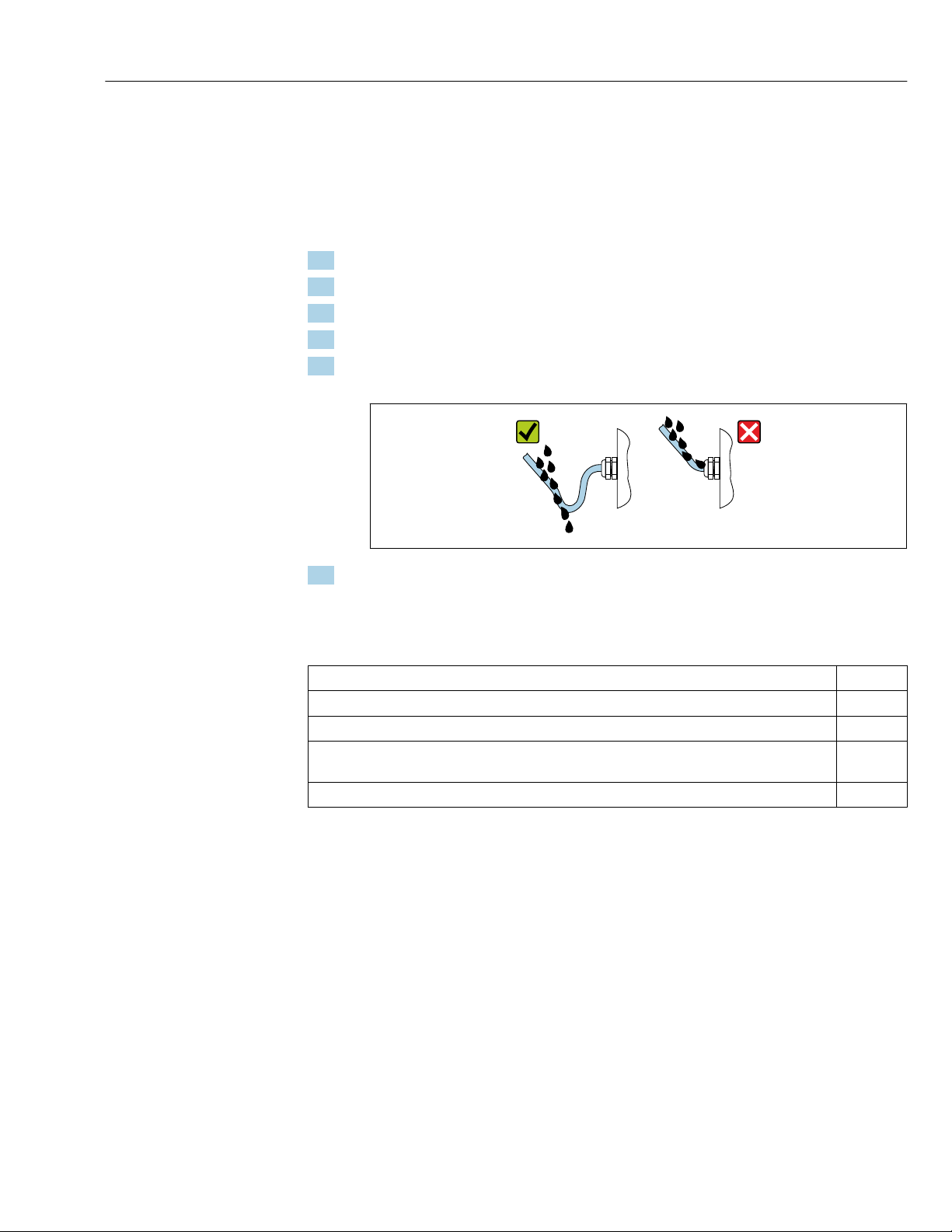
Proline Promass F 300 EtherNet/IP Electrical connection
7.6 Ensuring the degree of protection
The measuring device fulfills all the requirements for the IP66/67 degree of protection,
Type 4X enclosure.
To guarantee IP66/67 degree of protection, Type 4X enclosure, carry out the following
steps after the electrical connection:
1. Check that the housing seals are clean and fitted correctly.
2. Dry, clean or replace the seals if necessary.
3. Tighten all housing screws and screw covers.
4. Firmly tighten the cable glands.
5. To ensure that moisture does not enter the cable entry:
Route the cable so that it loops down before the cable entry ("water trap").
6. Insert dummy plugs into unused cable entries.
7.7 Post-connection check
Are cables or the device undamaged (visual inspection)?
Do the cables used meet the requirements?
Do the cables have adequate strain relief?
Are all the cable glands installed, firmly tightened and leak-tight? Cable run with "water trap"
→ 49 ?
If supply voltage is present, do values appear on the display module?
A0029278
49
Page 50
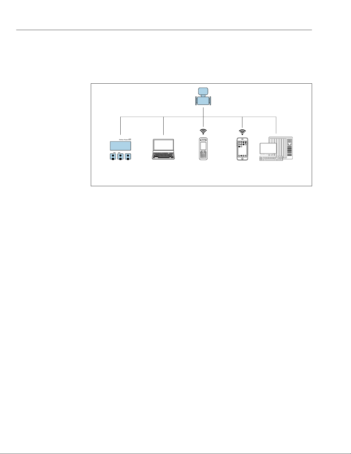
Operation options Proline Promass F 300 EtherNet/IP
1
2 3 4
5
E+-
ESC
8 Operation options
8.1 Overview of operation options
A0034513
1 Local operation via display module
2 Computer with Web browser (e.g. Internet Explorer) or with operating tool (e.g. FieldCare, DeviceCare, AMS
Device Manager, SIMATIC PDM)
3 Field Xpert SFX350 or SFX370
5 Mobile handheld terminal
6 Control system (e.g. PLC)
50
Page 51

Proline Promass F 300 EtherNet/IP Operation options
8.2 Structure and function of the operating menu
8.2.1 Structure of the operating menu
For an overview of the operating menu for experts: "Description of Device Parameters"
document supplied with the device→ 255
51
Page 52
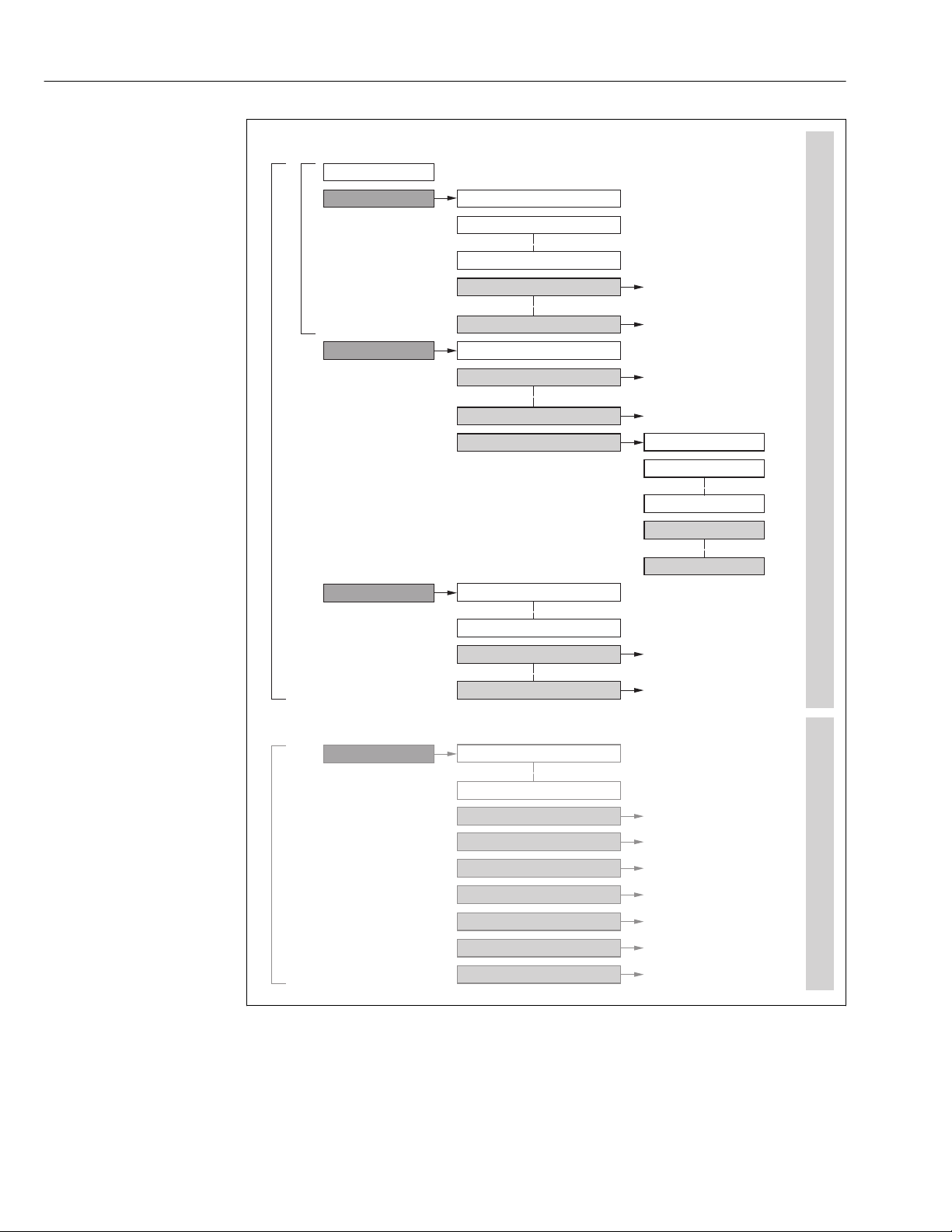
Operation options Proline Promass F 300 EtherNet/IP
!
Expert
System
Sensor
Communication
Application
Diagnostics
Access status display
Output
Operating menu for experts
Language
Operatation Language
Parameter 1
Setup
Submenu 1
Submenu n
Device tag
Advanced setup
Enter access code
Parameter 1
Parameter n
Submenu 1
Submenu n
Diagnostics
Parameter 1
Parameter n
Submenu 1
Submenu n
Operating menu for operators and maintenances
Parameter n
Operator
Maintenance
Task-oriented
Function-oriented
Expert
Wizard 1 / Parameter 1
Wizard n / Parameter n
Parameter n
Input
52
16 Schematic structure of the operating menu
A0018237-EN
Page 53
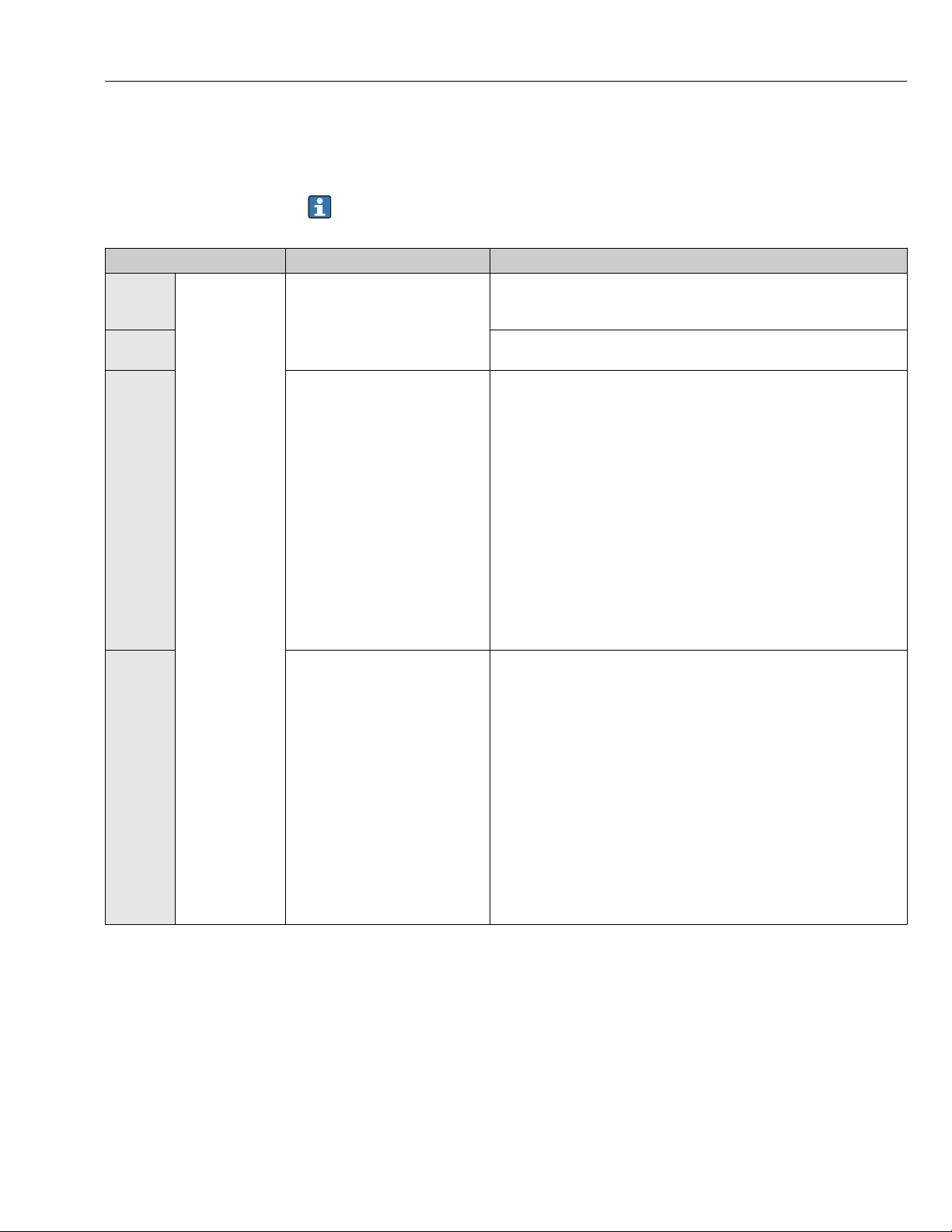
Proline Promass F 300 EtherNet/IP Operation options
8.2.2 Operating philosophy
The individual parts of the operating menu are assigned to certain user roles (operator,
maintenance etc.). Each user role contains typical tasks within the device lifecycle.
For custody transfer, once the device has been put into circulation or sealed, its
operation is restricted.
Menu/parameter User role and tasks Content/meaning
Language task-oriented Role "Operator", "Maintenance"
Tasks during operation:
• Configuring the operational
Operation • Configuring the operational display (e.g. display format, display contrast)
Setup "Maintenance" role
Diagnostics "Maintenance" role
display
• Reading measured values
Commissioning:
• Configuration of the
measurement
• Configuration of the inputs and
outputs
• Configuration of the
communication interface
Fault elimination:
• Diagnostics and elimination of
process and device errors
• Measured value simulation
• Defining the operating language
• Defining the Web server operating language
• Resetting and controlling totalizers
• Resetting and controlling totalizers
Wizards for fast commissioning:
• Set the system units
• Configuration of the communication interface
• Define the medium
• Display I/O/configuration
• Configure the inputs
• Configure the outputs
• Configuring the operational display
• Define the output conditioning
• Set the low flow cut off
• Configure partial and empty pipe detection
Advanced setup
• For more customized configuration of the measurement (adaptation to
special measuring conditions)
• Configuration of totalizers
• Configure the WLAN settings
• Administration (define access code, reset measuring device)
Contains all parameters for error detection and analyzing process and device
errors:
• Diagnostic list
Contains up to 5 currently pending diagnostic messages.
• Event logbook
Contains event messages that have occurred.
• Device information
Contains information for identifying the device.
• Measured values
Contains all current measured values.
• Data logging submenu with "Extended HistoROM" order option
Storage and visualization of measured values
• Heartbeat
The functionality of the device is checked on demand and the verification
results are documented.
• Simulation
Is used to simulate measured values or output values.
53
Page 54
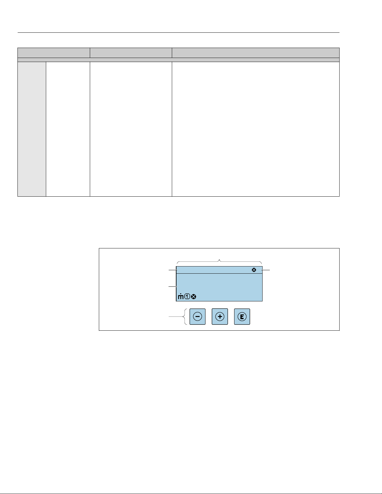
Operation options Proline Promass F 300 EtherNet/IP
X X X X X X XX X
2
1
3
kg/h
1120.50
F
Menu/parameter User role and tasks Content/meaning
Expert function-oriented Tasks that require detailed
knowledge of the function of the
device:
• Commissioning measurements
under difficult conditions
• Optimal adaptation of the
measurement to difficult
conditions
• Detailed configuration of the
communication interface
• Error diagnostics in difficult cases
8.3 Access to the operating menu via the local display
8.3.1 Operational display
Contains all the parameters of the device and makes it possible to access
these parameters directly using an access code. The structure of this menu is
based on the function blocks of the device:
• System
Contains all higher-order device parameters which do not concern the
measurement or the communication interface.
• Sensor
Configuration of the measurement.
• Input
Configuring the status input.
• Output
Configuring of the analog current outputs as well as the pulse/frequency
and switch output.
• Communication
Configuration of the digital communication interface and the Web server.
• Application
Configure the functions that go beyond the actual measurement (e.g.
totalizer).
• Diagnostics
Error detection and analysis of process and device errors and for device
simulation and Heartbeat Technology.
54
1 Operational display
2 Device tag
3 Status area
4 Display area for measured values (4-line)
5 Operating elements→ 60
A0029348
Page 55
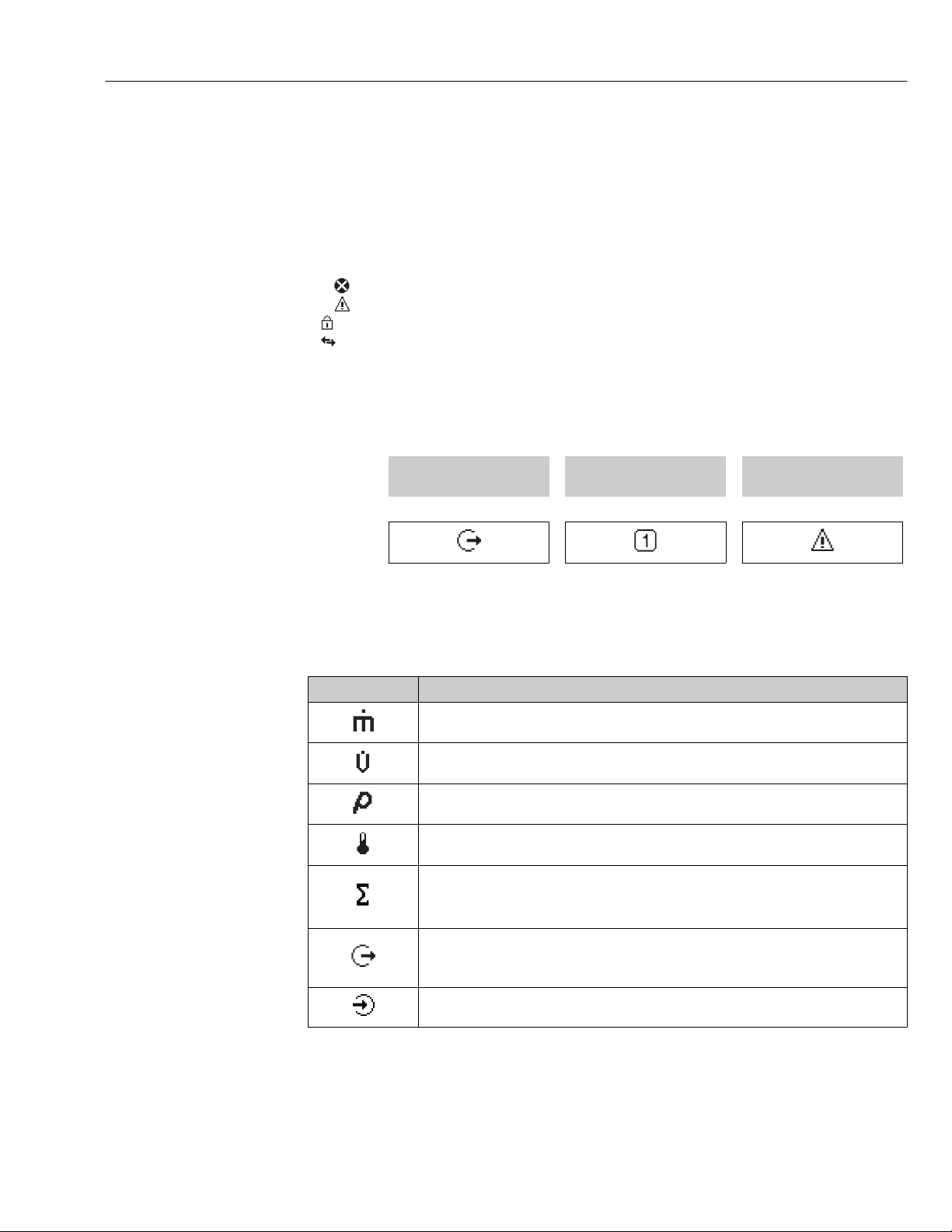
Proline Promass F 300 EtherNet/IP Operation options
Status area
The following symbols appear in the status area of the operational display at the top right:
• Status signals→ 189
– F: Failure
– C: Function check
– S: Out of specification
– M: Maintenance required
• Diagnostic behavior→ 190
– : Alarm
– : Warning
• : Locking (the device is locked via the hardware )
• : Communication (communication via remote operation is active)
Display area
In the display area, each measured value is prefaced by certain symbol types for further
description:
Measured variable Measurement channel
Example
Measured values
Symbol Meaning
Mass flow
• Volume flow
• Corrected volume flow
• Density
• Reference density
Temperature
Totalizer
Output
Diagnostic behavior
number
↓ ↓ ↓
Appears only if a diagnostics
event is present for this
measured variable.
The measurement channel number indicates which of the three totalizers is
displayed.
The measurement channel number indicates which of the outputs is displayed.
Status input
55
Page 56
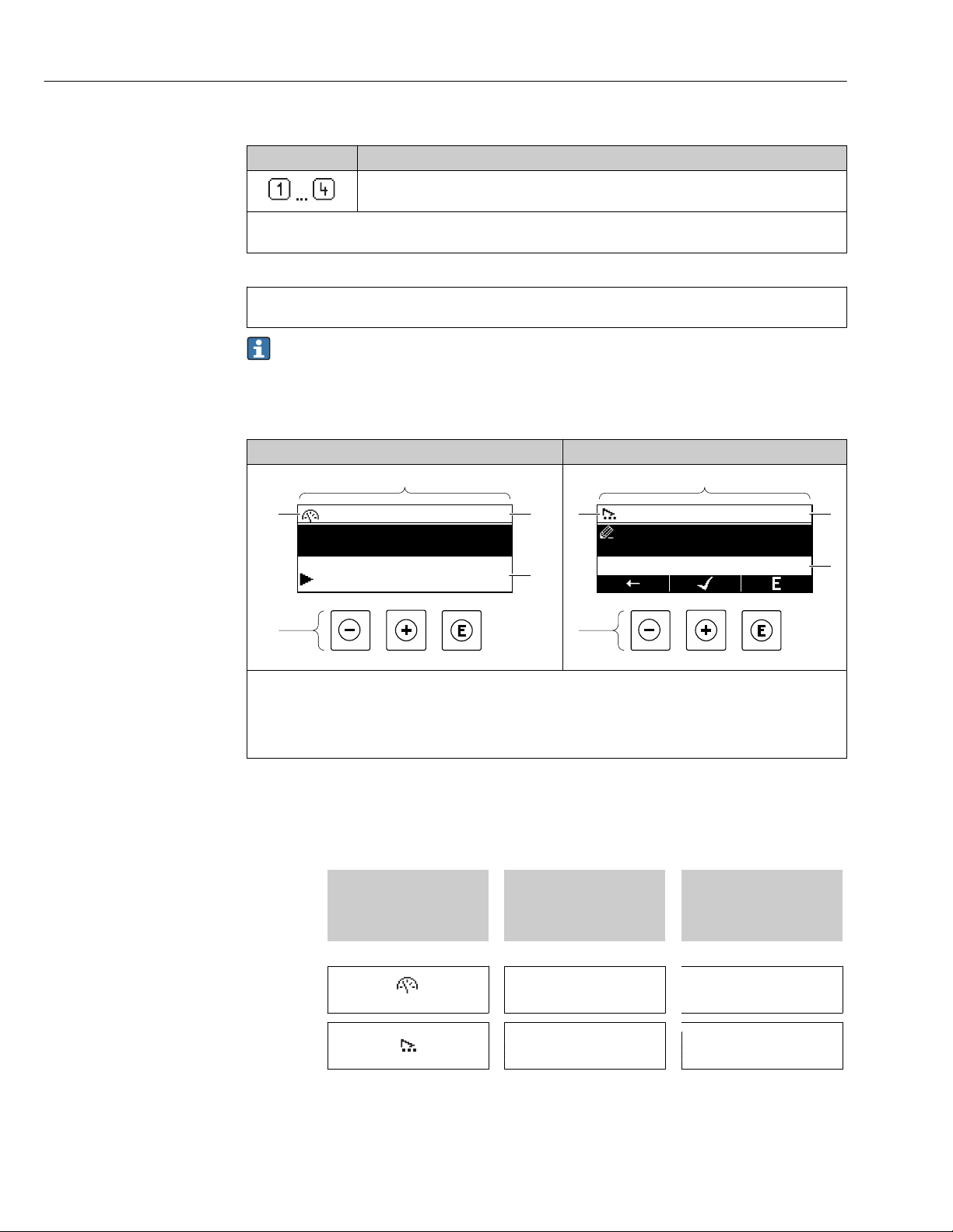
Operation options Proline Promass F 300 EtherNet/IP
4
2
1
3
/../Operation
0091-1
Access stat.disp
Operator
Locking status
Display
4
2
1
3
/../Select medium
Select medium
Liquid
Measurement channel numbers
Symbol Meaning
Measurement channel 1 to 4
The measurement channel number is displayed only if more than one channel is present for the same measured
variable type (e.g. Totalizer 1 to 3).
Diagnostic behavior
The diagnostic behavior pertains to a diagnostic event that is relevant to the displayed measured variable.
For information on the symbols → 190
The number and display format of the measured values can be configured via the
Format display parameter (→ 129).
8.3.2 Navigation view
In the submenu In the wizard
1
Navigation view
2
Navigation path to current position
3
Status area
4
Display area for navigation
5
Operating elements → 60
A0013993-EN
A0013995-EN
Navigation path
The navigation path - displayed at the top left in the navigation view - consists of the
following elements:
• In the submenu:
Display symbol for menu
• In the wizard:
Display symbol for wizard
↓ ↓ ↓
Examples / ../ Display
Omission symbol for
operating menu levels in
between
/ ../ Display
Name of current
• Submenu
• Wizard
• Parameters
56
Page 57
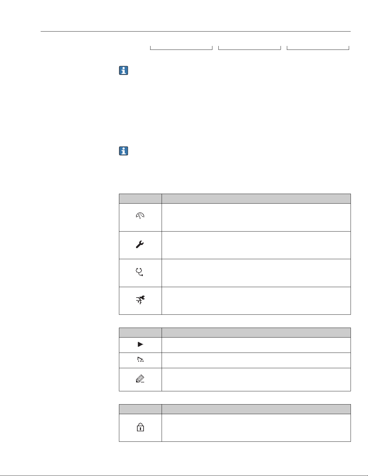
Proline Promass F 300 EtherNet/IP Operation options
For more information about the icons in the menu, refer to the "Display area" section
→ 57
Status area
The following appears in the status area of the navigation view in the top right corner:
• In the submenu
– The direct access code for the parameter you are navigating to (e.g. 0022-1)
– If a diagnostic event is present, the diagnostic behavior and status signal
• In the wizard
If a diagnostic event is present, the diagnostic behavior and status signal
• For information on the diagnostic behavior and status signal → 189
• For information on the function and entry of the direct access code → 63
Display area
Menus
Symbol Meaning
Operation
Appears:
• In the menu next to the "Operation" selection
• At the left in the navigation path in the Operation menu
Setup
Appears:
• In the menu next to the "Setup" selection
• At the left in the navigation path in the Setup menu
Diagnostics
Appears:
• In the menu next to the "Diagnostics" selection
• At the left in the navigation path in the Diagnostics menu
Expert
Appears:
• In the menu next to the "Expert" selection
• At the left in the navigation path in the Expert menu
Submenus, wizards, parameters
Symbol Meaning
Submenu
Wizard
Parameters within a wizard
No display symbol exists for parameters in submenus.
Locking
Symbol Meaning
Parameter locked
When displayed in front of a parameter name, indicates that the parameter is locked.
• By a user-specific access code
• By the hardware write protection switch
57
Page 58
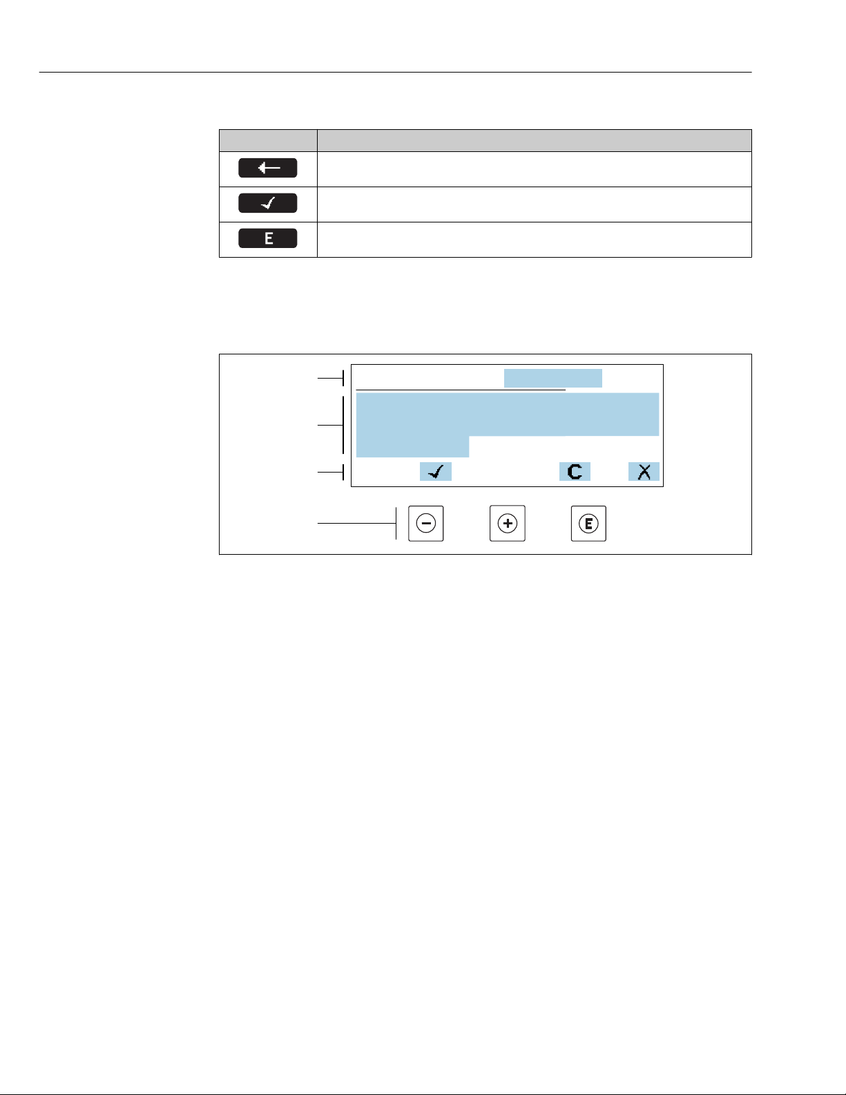
Operation options Proline Promass F 300 EtherNet/IP
+0.000 Xx
0 1 2 3 4
+
5
1
2
3
4
6 7
8
9
–
Wizard operation
Symbol Meaning
Switches to the previous parameter.
Confirms the parameter value and switches to the next parameter.
Opens the editing view of the parameter.
8.3.3 Editing view
Numeric editor
A0034250
17 For entering values in parameters (e.g. limit values)
1 Entry display area
2 Input screen
3 Confirm, delete or reject entry
4 Operating elements
58
Page 59
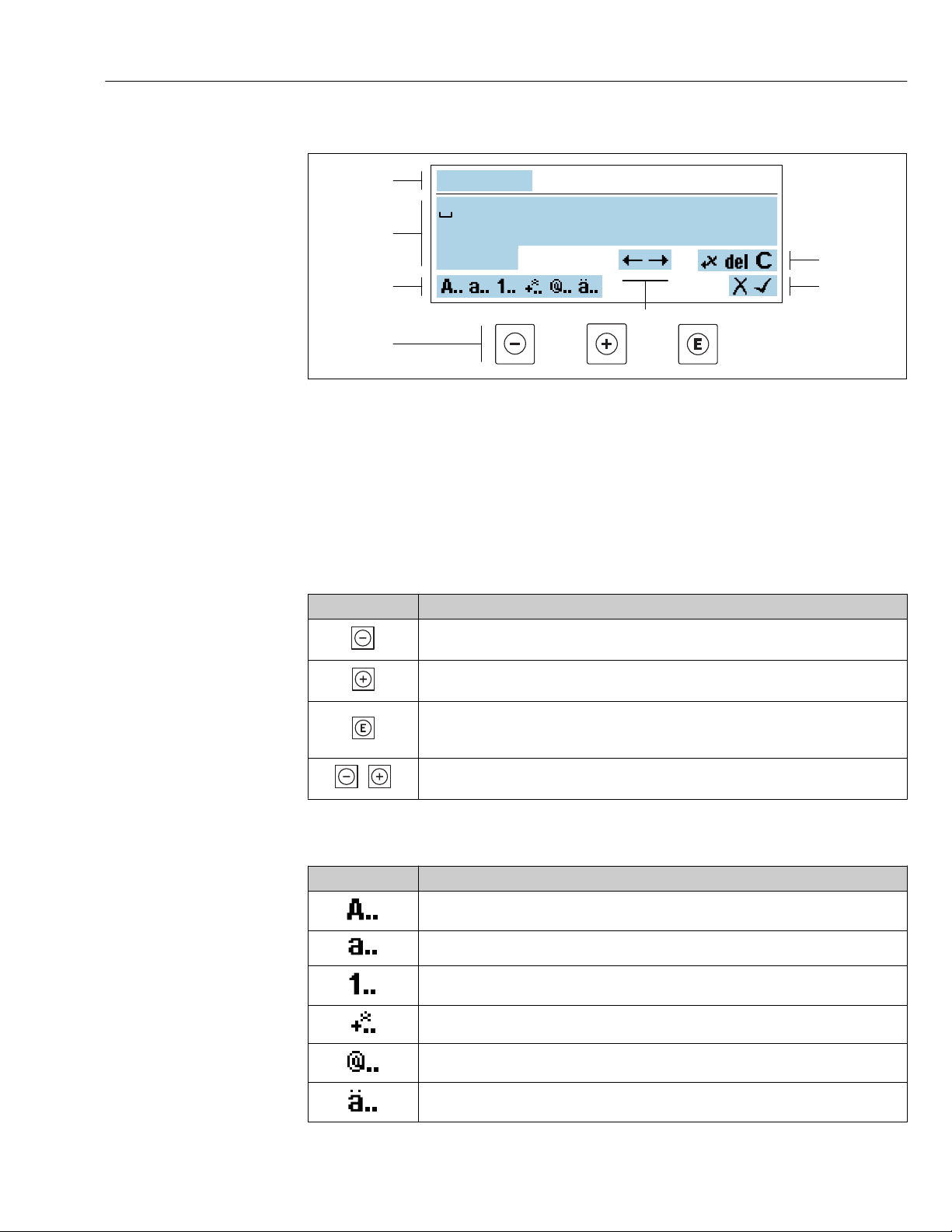
Proline Promass F 300 EtherNet/IP Operation options
Xxxxxxx
A B C D E F G H I J K
M N O P Q R S T U V W
X YLZ
1
2
3
5
6
7
4
+
Text editor
A0034114
18 For entering text in parameters (e.g. tag name)
1 Entry display area
2 Current input screen
3 Change input screen
4 Operating elements
5 Move entry position
6 Delete entry
7 Reject or confirm entry
Using the operating elements in the editing view
Operating key(s) Meaning
Minus key
Move the entry position to the left.
Plus key
Move the entry position to the right.
Enter key
• Press the key briefly: confirm your selection.
• Press the key for 2 s: confirm the entry.
Escape key combination (press keys simultaneously)
Close the editing view without accepting the changes.
Input screens
Symbol Meaning
Upper case
Lower case
Numbers
Punctuation marks and special characters: = + – * / ² ³ ¼ ½ ¾ ( ) [ ] < > { }
Punctuation marks and special characters: ' " `^. , ; : ? ! % µ ° € $ £ ¥ § @ # / \ I ~ & _
Umlauts and accents
59
Page 60
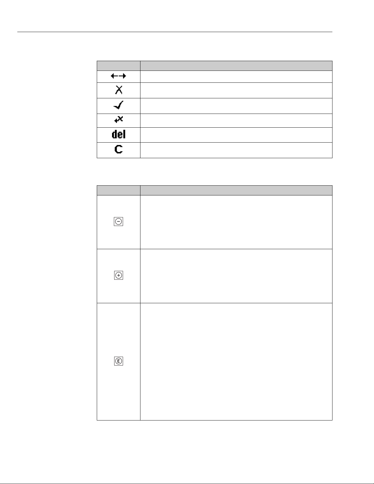
Operation options Proline Promass F 300 EtherNet/IP
Controlling data entries
Symbol Meaning
Move entry position
Reject entry
Confirm entry
Delete character immediately to the left of the entry position
Delete character immediately to the right of the entry position
Clear all the characters entered
8.3.4 Operating elements
Operating key(s) Meaning
Minus key
In a menu, submenu
Moves the selection bar upwards in a choose list.
With a Wizard
Confirms the parameter value and goes to the previous parameter.
With a text and numeric editor
Move the entry position to the left.
Plus key
In a menu, submenu
Moves the selection bar downwards in a choose list.
With a Wizard
Confirms the parameter value and goes to the next parameter.
With a text and numeric editor
Move the entry position to the right.
Enter key
For operational display
• Pressing the key briefly opens the operating menu.
• Pressing the key for 2 s opens the context menu including the option for activating the
keypad lock.
In a menu, submenu
• Pressing the key briefly:
– Opens the selected menu, submenu or parameter.
– Starts the wizard.
– If help text is open, closes the help text of the parameter.
• Pressing the key for 2 s for parameter:
If present, opens the help text for the function of the parameter.
With a Wizard
Opens the editing view of the parameter.
With a text and numeric editor
• Press the key briefly: confirm your selection.
• Press the key for 2 s: confirm the entry.
60
Page 61
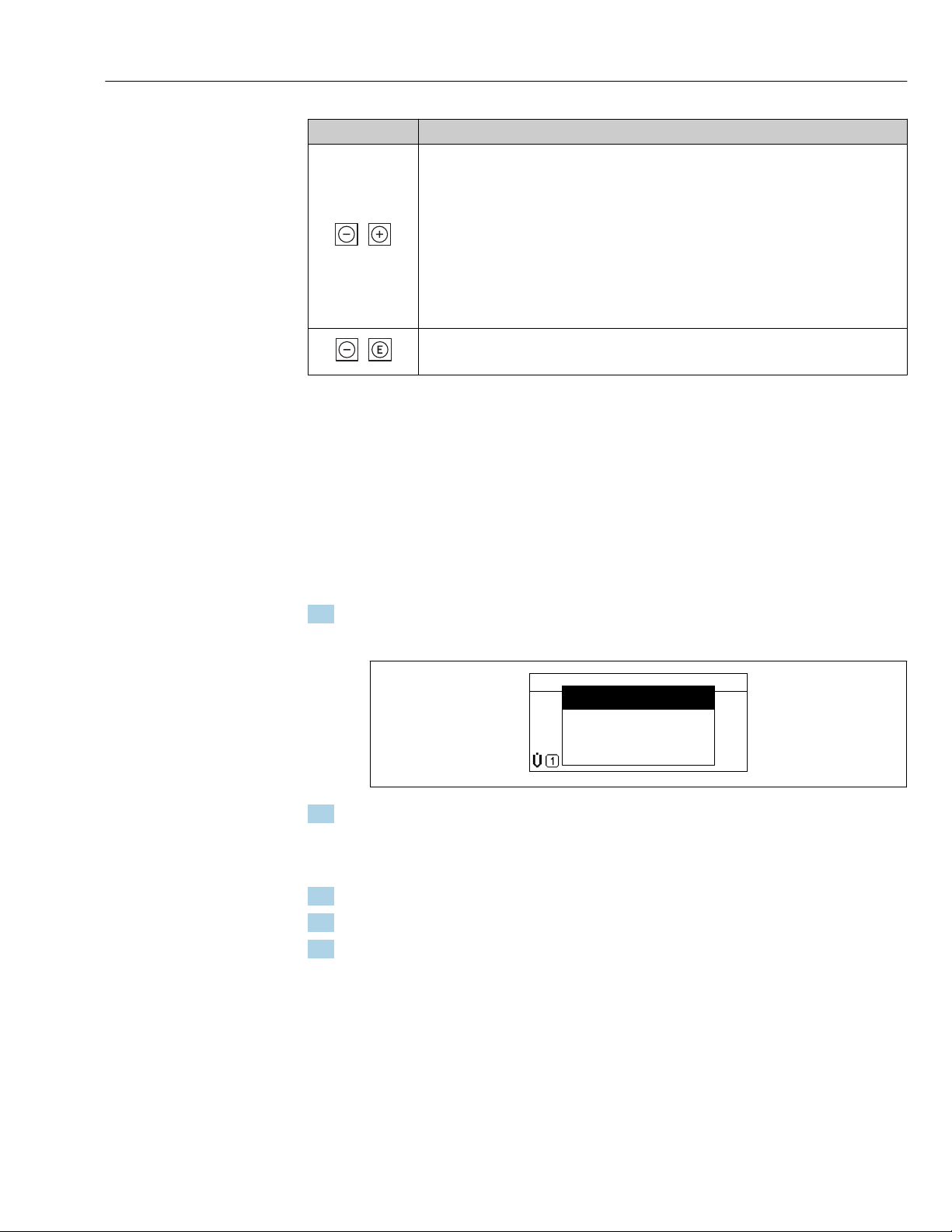
Proline Promass F 300 EtherNet/IP Operation options
+
+
XXXXXXXXXX
l/h
Setup
Conf.backup
Simulation
Keylock on
Operating key(s) Meaning
Escape key combination (press keys simultaneously)
In a menu, submenu
• Pressing the key briefly:
– Exits the current menu level and takes you to the next higher level.
– If help text is open, closes the help text of the parameter.
• Pressing the key for 2 s returns you to the operational display ("home position").
With a Wizard
Exits the wizard and takes you to the next higher level.
With a text and numeric editor
Close the editing view without accepting the changes.
Minus/Enter key combination (press the keys simultaneously)
Press the key for 3 s: deactivate the keypad lock.
8.3.5 Opening the context menu
Using the context menu, the user can call up the following menus quickly and directly from
the operational display:
• Setup
• Data backup
• Simulation
Calling up and closing the context menu
The user is in the operational display.
1. Press for 2 s.
The context menu opens.
2. Press + simultaneously.
The context menu is closed and the operational display appears.
Calling up the menu via the context menu
1. Open the context menu.
2. Press to navigate to the desired menu.
3. Press to confirm the selection.
The selected menu opens.
A0034608-EN
61
Page 62
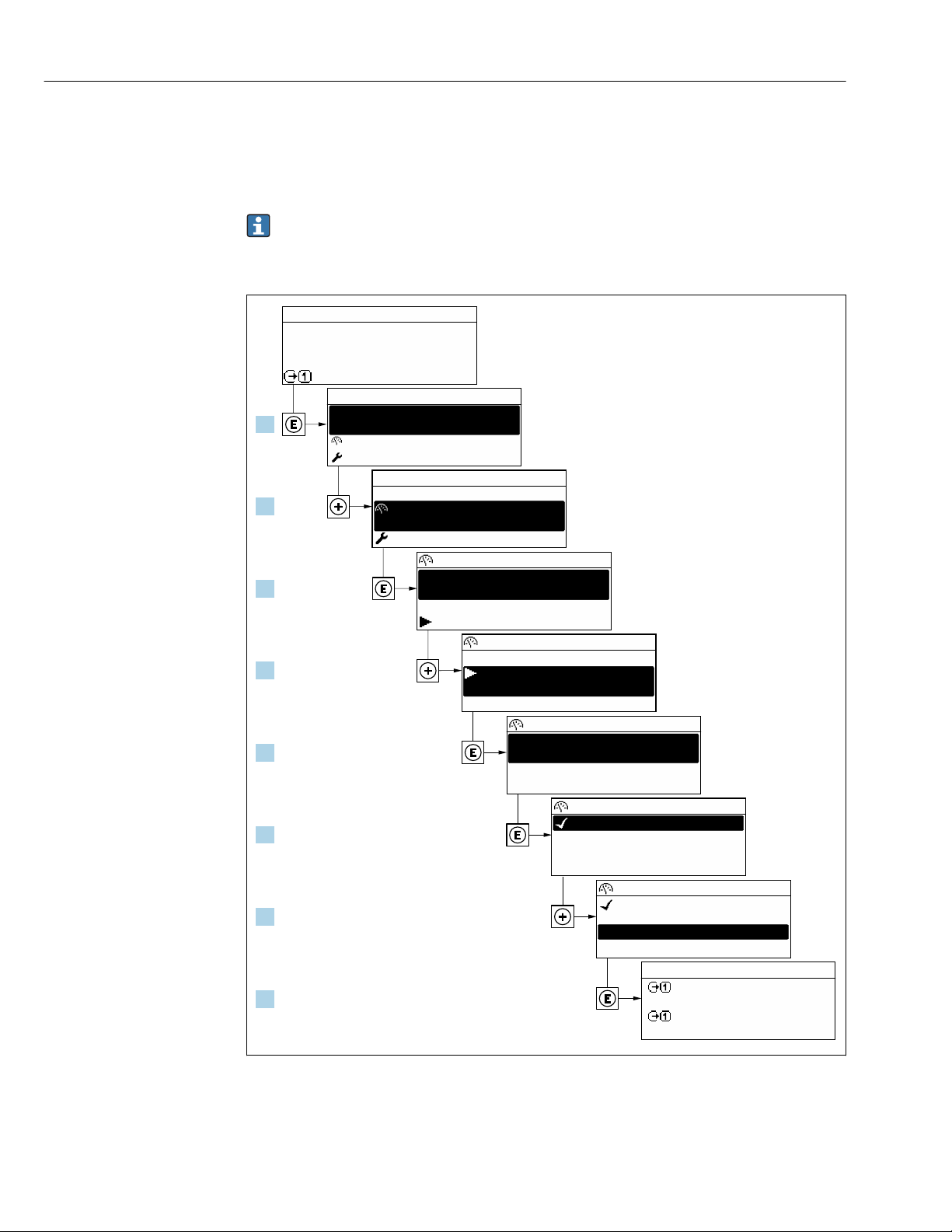
Operation options Proline Promass F 300 EtherNet/IP
X X X X X X XX X
20.50
0104-1
2 s
0091-1
0098-1
0098-1
0098-1
X X X X X X XX X
10.50
2800
Hz
mA
3.
4.
5.
6.
7.
8.
1.
2.
Display/operat.
Display/operat.
Setup
Main menu
English
Main menu
Format display
/ ../Display
Contrast display
Display intervall
1 value, max.
Setup
Access stat.disp
/ ../Display/operat.
Display
Locking status
1 value, max.
/ ../Format display
2 values
Val. large+2val.
Bargr. + 1 value
Locking status
/ ../Display/operat.
Display
1 value, max.
/ ../Format display
2 values
Val. large+2val.
Bargr. + 1 value
Operator
Language
Language
8.3.6 Navigating and selecting from list
Different operating elements are used to navigate through the operating menu. The
navigation path is displayed on the left in the header. Icons are displayed in front of the
individual menus. These icons are also shown in the header during navigation.
For an explanation of the navigation view with symbols and operating elements
→ 56
Example: Setting the number of displayed measured values to "2 values"
62
A0029562-EN
Page 63
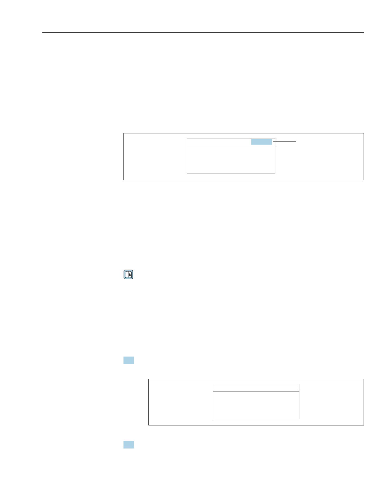
Proline Promass F 300 EtherNet/IP Operation options
1
00914-2
Ent.accesscode
Enteraccesscodetodisable
writeprotec.
8.3.7 Calling the parameter directly
A parameter number is assigned to every parameter to be able to access a parameter
directly via the onsite display. Entering this access code in the Direct access parameter
calls up the desired parameter directly.
Navigation path
Expert → Direct access
The direct access code consists of a 5-digit number (at maximum) and the channel
number, which identifies the channel of a process variable: e.g. 00914-2. In the navigation
view, this appears on the right-hand side in the header of the selected parameter.
A0029414
1 Direct access code
Note the following when entering the direct access code:
• The leading zeros in the direct access code do not have to be entered.
Example: Enter "914" instead of "00914"
• If no channel number is entered, channel 1 is accessed automatically.
Example: Enter 00914 → Assign process variable parameter
• If a different channel is accessed: Enter the direct access code with the corresponding
channel number.
Example: Enter 00914-2 → Assign process variable parameter
For the direct access codes of the individual parameters, see the "Description of Device
Parameters" document for the device
8.3.8 Calling up help text
Help text is available for some parameters and can be called up from the navigation view.
The help text provides a brief explanation of the parameter function and thereby supports
swift and safe commissioning.
Calling up and closing the help text
The user is in the navigation view and the selection bar is on a parameter.
1. Press for 2 s.
The help text for the selected parameter opens.
A0014002-EN
19 Example: Help text for parameter "Enter access code"
2. Press + simultaneously.
The help text is closed.
63
Page 64
Operation options Proline Promass F 300 EtherNet/IP
Ent.accesscode
Invalidoroutofrangeinput
value
Max:9999
Min:0
8.3.9 Changing the parameters
Parameters can be changed via the numeric editor or text editor.
• Numeric editor: Change values in a parameter, e.g. specifications for limit values.
• Text editor: Enter text in a parameter, e.g. tag name.
A message is displayed if the value entered is outside the permitted value range.
A0014049-EN
For a description of the editing view - consisting of the text editor and numeric editor
- with symbols → 58, for a description of the operating elements → 60
8.3.10 User roles and related access authorization
The two user roles "Operator" and "Maintenance" have different write access to the
parameters if the customer defines a user-specific access code. This protects the device
configuration via the local display from unauthorized access → 167.
Defining access authorization for user roles
An access code is not yet defined when the device is delivered from the factory. Access
authorization (read and write access) to the device is not restricted and corresponds to the
"Maintenance" user role.
Define the access code.
‣
The "Operator" user role is redefined in addition to the "Maintenance" user role.
Access authorization differs for the two user roles.
Access authorization to parameters: "Maintenance" user role
Access code status Read access Write access
An access code has not yet been defined
(factory setting).
After an access code has been defined.
1) The user only has write access after entering the access code.
1)
Access authorization to parameters: "Operator" user role
Access code status Read access Write access
After an access code has been defined. ––
1) Despite the defined access code, certain parameters can always be modified and thus are excepted from
the write protection, as they do not affect the measurement. Refer to the "Write protection via access code"
section
1)
64
The user role with which the user is currently logged on is indicated by the Access
status parameter. Navigation path: Operation → Access status
Page 65
Proline Promass F 300 EtherNet/IP Operation options
8.3.11 Disabling write protection via access code
If the -symbol appears on the local display in front of a parameter, the parameter is
write-protected by a user-specific access code and its value cannot be changed at the
moment using local operation → 167.
Parameter write protection via local operation can be disabled by entering the user-specific
access code in the Enter access code parameter (→ 142) via the respective access
option.
1. After you press , the input prompt for the access code appears.
2. Enter the access code.
The -symbol in front of the parameters disappears; all previously write-
protected parameters are now re-enabled.
8.3.12 Enabling and disabling the keypad lock
The keypad lock makes it possible to block access to the entire operating menu via local
operation. As a result, it is no longer possible to navigate through the operating menu or
change the values of individual parameters. Users can only read the measured values on
the operational display.
The keypad lock is switched on and off via the context menu.
Switching on the keypad lock
The keypad lock is switched on automatically:
• If the device has not been operated via the display for > 1 minute.
• Each time the device is restarted.
To activate the keylock manually:
1. The device is in the measured value display.
Press for at least 2 seconds.
A context menu appears.
2. In the context menu select the Keylock on option.
The keypad lock is switched on.
If the user attempts to access the operating menu while the keypad lock is active, the
Keylock on message appears.
Switching off the keypad lock
1. The keypad lock is switched on.
Press for at least 2 seconds.
A context menu appears.
2. In the context menu select the Keylock off option.
The keypad lock is switched off.
65
Page 66
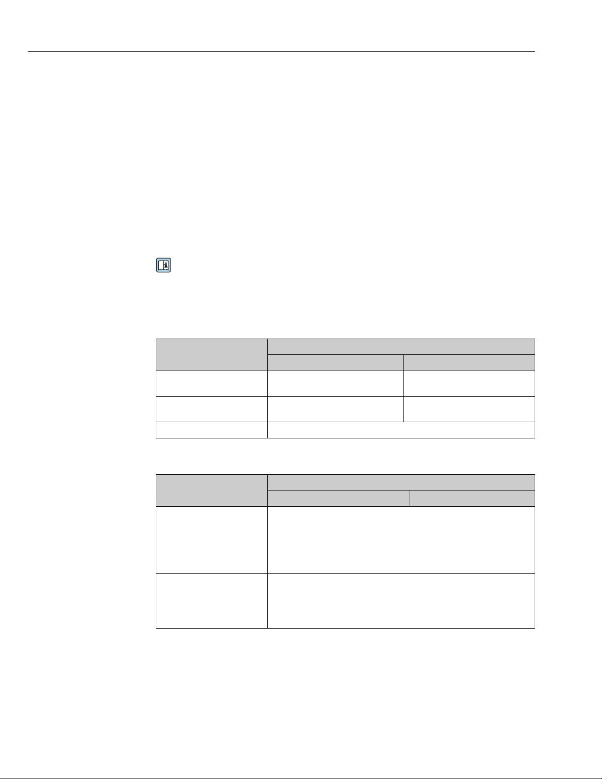
Operation options Proline Promass F 300 EtherNet/IP
8.4 Access to the operating menu via the Web browser
8.4.1 Function range
Thanks to the integrated Web server, the device can be operated and configured via a Web
browser and via a service interface (CDI-RJ45) or via a WLAN interface. The structure of
the operating menu is the same as for the local display. In addition to the measured values,
status information on the device is also displayed and allows the user to monitor the status
of the device. Furthermore the device data can be managed and the network parameters
can be configured.
A device that has a WLAN interface (can be ordered as an option) is required for the
WLAN connection: order code for "Display; operation", option G "4-line, illuminated; touch
control + WLAN". The device acts as an Access Point and enables communication by
computer or a mobile handheld terminal.
For additional information on the Web server, refer to the Special Documentation for
the device → 256
8.4.2 Prerequisites
Computer hardware
Hardware Interface
CDI-RJ45 WLAN
Interface The computer must have an RJ45
interface.
Connection Standard Ethernet cable with RJ45
connector.
Screen Recommended size: ≥12" (depends on the screen resolution)
The operating unit must have a
WLAN interface.
Connection via Wireless LAN.
Computer software
Software Interface
CDI-RJ45 WLAN
Recommended operating
systems
Web browsers supported • Microsoft Internet Explorer 8 or higher
• Microsoft Windows 7 or higher.
• Mobile operating systems:
– iOS
– Android
Microsoft Windows XP is supported.
• Microsoft Edge
• Mozilla Firefox
• Google Chrome
• Safari
66
Page 67
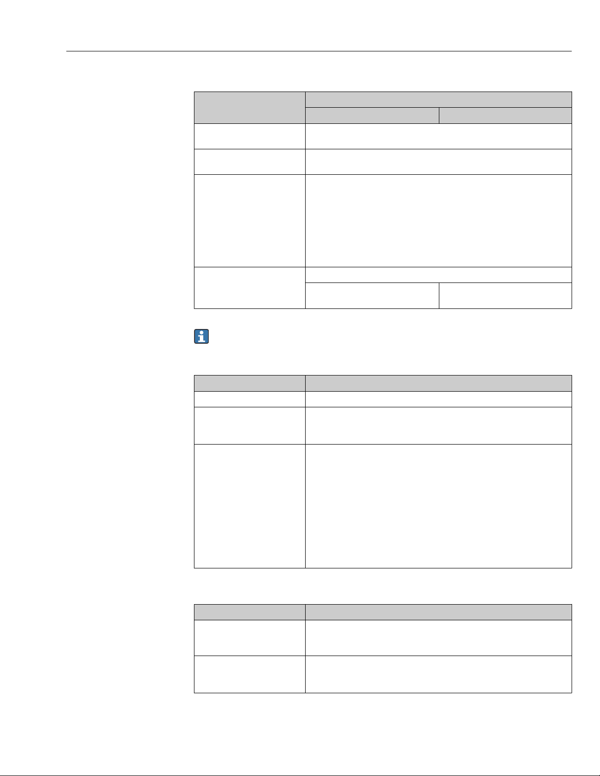
Proline Promass F 300 EtherNet/IP Operation options
Computer settings
Settings Interface
CDI-RJ45 WLAN
User rights Appropriate user rights (e.g. administrator rights) for TCP/IP and proxy server
settings are necessary (for adjusting the IP address, subnet mask etc.).
Proxy server settings of the
Web browser
JavaScript JavaScript must be enabled.
Network connections Only the active network connections to the measuring device should be used.
The Web browser setting Use a Proxy Server for Your LAN must be
deselected .
If JavaScript cannot be enabled:
enter http://192.168.1.212/basic.html in the address line of the Web
browser. A fully functional but simplified version of the operating menu
structure starts in the Web browser.
When installing a new firmware version: To enable correct data display,
clear the temporary memory (cache) of the Web browser under Internet
options.
Switch off all other network
connections such as WLAN.
Switch off all other network
connections.
In the event of connection problems: → 185
Measuring device: Via CDI-RJ45 service interface
Device CDI-RJ45 service interface
Measuring device The measuring device has an RJ45 interface.
Web server Web server must be enabled; factory setting: ON
For information on enabling the Web server → 72
IP address If the IP address of the device is not known:
• The IP address can be read out via local operation:
Diagnostics → Device information → IP address
• Communication with the Web server can be established via the default IP
address 192.168.1.212.
The DHCP function is enabled in the device at the factory, i.e. the device
expects an IP address to be assigned by the network. This function can be
disabled and the device can be set to the default IP address 192.168.1.212:
set DIP switch No. 4 from OFF → ON.
Set the default IP address → 48.
Measuring device: via WLAN interface
Device WLAN interface
Measuring device The measuring device has a WLAN antenna:
• Transmitter with integrated WLAN antenna
• Transmitter with external WLAN antenna
Web server Web server and WLAN must be enabled; factory setting: ON
For information on enabling the Web server → 72
67
Page 68
Operation options Proline Promass F 300 EtherNet/IP
Device WLAN interface
IP address If the IP address of the device is not known:
• The IP address can be read out via local operation:
Diagnostics → Device information → IP address
• Communication with the Web server can be established via the default IP
address 192.168.1.212.
The DHCP function is enabled in the device at the factory, i.e. the device
expects an IP address to be assigned by the network. This function can be
disabled and the device can be set to the default IP address 192.168.1.212:
set DIP switch No. 4 from OFF → ON.
Set the default IP address → 48.
8.4.3 Establishing a connection
Via service interface (CDI-RJ45)
Preparing the measuring device
1. Depending on the housing version:
Release the securing clamp or securing screw of the housing cover.
2. Depending on the housing version:
Unscrew or open the housing cover.
3. The location of the connection socket depends on the measuring device and the
communication protocol:
Connect the computer to the RJ45 connector via the standard Ethernet connecting
cable .
Configuring the Internet protocol of the computer
The IP address can be assigned to the measuring device in a variety of ways:
• Dynamic Host Configuration Protocol (DHCP), factory setting:
The IP address is automatically assigned to the measuring device by the automation
system (DHCP server).
• Hardware addressing:
The IP address is set via DIP switches → 47.
• Software addressing:
The IP address is entered via the IP address parameter (→ 104) .
• DIP switch for "Default IP address":
To establish the network connection via the service interface (CDI-RJ45): the fixed IP
address 192.168.1.212 is used → 48.
The measuring device works with the Dynamic Host Configuration Protocol (DHCP), on
leaving the factory, i.e. the IP address of the measuring device is automatically assigned by
the automation system (DHCP server).
To establish a network connection via the service interface (CDI-RJ45): the "Default IP
address" DIP switch must be set to ON. The measuring device then has the fixed IP address:
192.168.1.212. This address can now be used to establish the network connection.
68
1. Via DIP switch 2, activate the default IP address 192.168.1.212: → 48.
2. Switch on the measuring device.
3. Connect to the computer using a cable → 74.
Page 69
Proline Promass F 300 EtherNet/IP Operation options
4. If a 2nd network card is not used, close all the applications on the notebook.
Applications requiring Internet or a network, such as e-mail, SAP applications,
Internet or Windows Explorer.
5. Close any open Internet browsers.
6. Configure the properties of the Internet protocol (TCP/IP) as defined in the table:
IP address 192.168.1.XXX; for XXX all numerical sequences except: 0, 212 and 255 → e.g.
192.168.1.213
Subnet mask 255.255.255.0
Default gateway 192.168.1.212 or leave cells empty
Via WLAN interface
Configuring the Internet protocol of the mobile terminal
NOTICE
If the WLAN connection is lost during the configuration, settings made may be lost.
Make sure that the WLAN connection is not disconnected while configuring the device.
‣
NOTICE
In principle, avoid simultaneous access to the measuring device via the service
interface (CDI-RJ45) and the WLAN interface from the same mobile terminal. This
could cause a network conflict.
Only activate one service interface (CDI-RJ45 service interface or WLAN interface).
‣
If simultaneous communication is necessary: configure different IP address ranges, e.g.
‣
192.168.0.1 (WLAN interface) and 192.168.1.212 (CDI-RJ45 service interface).
Preparing the mobile terminal
Enable WLAN reception on the mobile terminal.
‣
Establishing a connection from the mobile terminal to the measuring device
1. In the WLAN settings of the mobile terminal:
Select the measuring device using the SSID (e.g. EH_Promass_300_A802000).
2. If necessary, select the WPA2 encryption method.
3. Enter the password: serial number of the measuring device ex-works (e.g.
L100A802000).
LED on display module flashes: it is now possible to operate the measuring device
with the Web browser, FieldCare or DeviceCare.
The serial number can be found on the nameplate.
To ensure the safe and swift assignment of the WLAN network to the measuring
point, it is advisable to change the SSID name. It should be possible to clearly assign
the new SSID name to the measuring point (e.g. tag name) because it is displayed as
the WLAN network.
Disconnecting
After configuring the device:
‣
Terminate the WLAN connection between the operating unit and measuring device.
69
Page 70
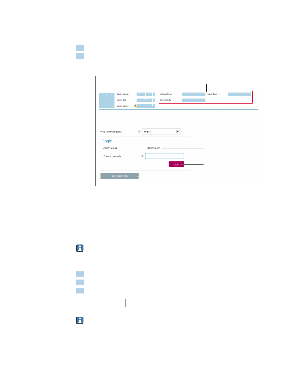
Operation options Proline Promass F 300 EtherNet/IP
6
7
8
9
10
1 52 3 4
Starting the Web browser
1. Start the Web browser on the computer.
2. Enter the IP address of the Web server in the address line of the Web browser:
192.168.1.212
The login page appears.
A0029417
1 Picture of device
2 Device name
3 Device tag
4 Status signal
5 Current measured values
6 Operating language
7 User role
8 Access code
9 Login
10 Reset access code (→ 163)
If a login page does not appear, or if the page is incomplete → 185
8.4.4 Logging on
1. Select the preferred operating language for the Web browser.
2. Enter the user-specific access code.
3. Press OK to confirm your entry.
Access code 0000 (factory setting); can be changed by customer
If no action is performed for 10 minutes, the Web browser automatically returns to
the login page.
70
Page 71
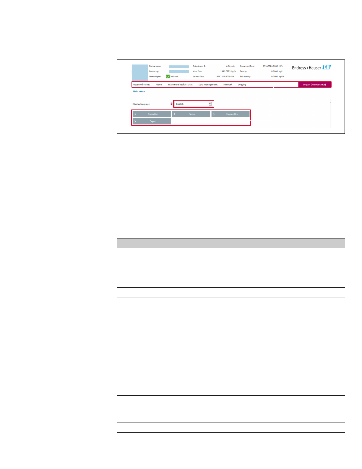
Proline Promass F 300 EtherNet/IP Operation options
2
1
3
8.4.5 User interface
A0029418
1 Function row
2 Local display language
3 Navigation area
Header
The following information appears in the header:
• Device name
• Device tag
• Device status with status signal → 192
• Current measured values
Function row
Functions Meaning
Measured values Displays the measured values of the measuring device
• Access to the operating menu from the measuring device
Menu
Device status Displays the diagnostic messages currently pending, listed in order of priority
Data
management
Network
configuration
Logout End the operation and call up the login page
• The structure of the operating menu is the same as for the local display
For detailed information on the structure of the operating menu, see the Operating
Instructions for the measuring device
Data exchange between PC and measuring device:
• Device configuration:
– Load settings from the device
(XML format, save configuration)
– Save settings to the device
(XML format, restore configuration)
• Logbook - Export Event logbook (.csv file)
• Documents - Export documents:
– Export backup data record
(.csv file, create documentation of the measuring point configuration)
– Verification report
(PDF file, only available with the "Heartbeat Verification" application package)
• File for system integration - If using fieldbuses, upload device drivers for system
integration from the measuring device:
EtherNet/IP: EDS file
• Firmware update - Flashing a firmware version
Configuration and checking of all the parameters required for establishing the connection to
the measuring device:
• Network settings (e.g. IP address, MAC address)
• Device information (e.g. serial number, firmware version)
71
Page 72
Operation options Proline Promass F 300 EtherNet/IP
Navigation area
If a function is selected in the function bar, the submenus of the function open in the
navigation area. The user can now navigate through the menu structure.
Working area
Depending on the selected function and the related submenus, various actions can be
performed in this area:
• Configuring parameters
• Reading measured values
• Calling up help text
• Starting an upload/download
8.4.6 Disabling the Web server
The Web server of the measuring device can be switched on and off as required using the
Web server functionality parameter.
Navigation
"Expert" menu → Communication → Web server
Parameter overview with brief description
Parameter Description Selection Factory setting
Web server functionality Switch the Web server on and off. • Off
• HTML Off
• On
Function scope of the "Web server functionality" parameter
Option Description
Off • The web server is completely disabled.
• Port 80 is locked.
On • The complete functionality of the web server is available.
• JavaScript is used.
• The password is transferred in an encrypted state.
• Any change to the password is also transferred in an encrypted state.
Enabling the Web server
If the Web server is disabled it can only be re-enabled with the Web server functionality
parameter via the following operating options:
• Via local display
• Via Bedientool "FieldCare"
• Via "DeviceCare" operating tool
On
72
8.4.7 Logging out
Before logging out, perform a data backup via the Data management function
(upload configuration from device) if necessary.
1. Select the Logout entry in the function row.
The home page with the Login box appears.
Page 73
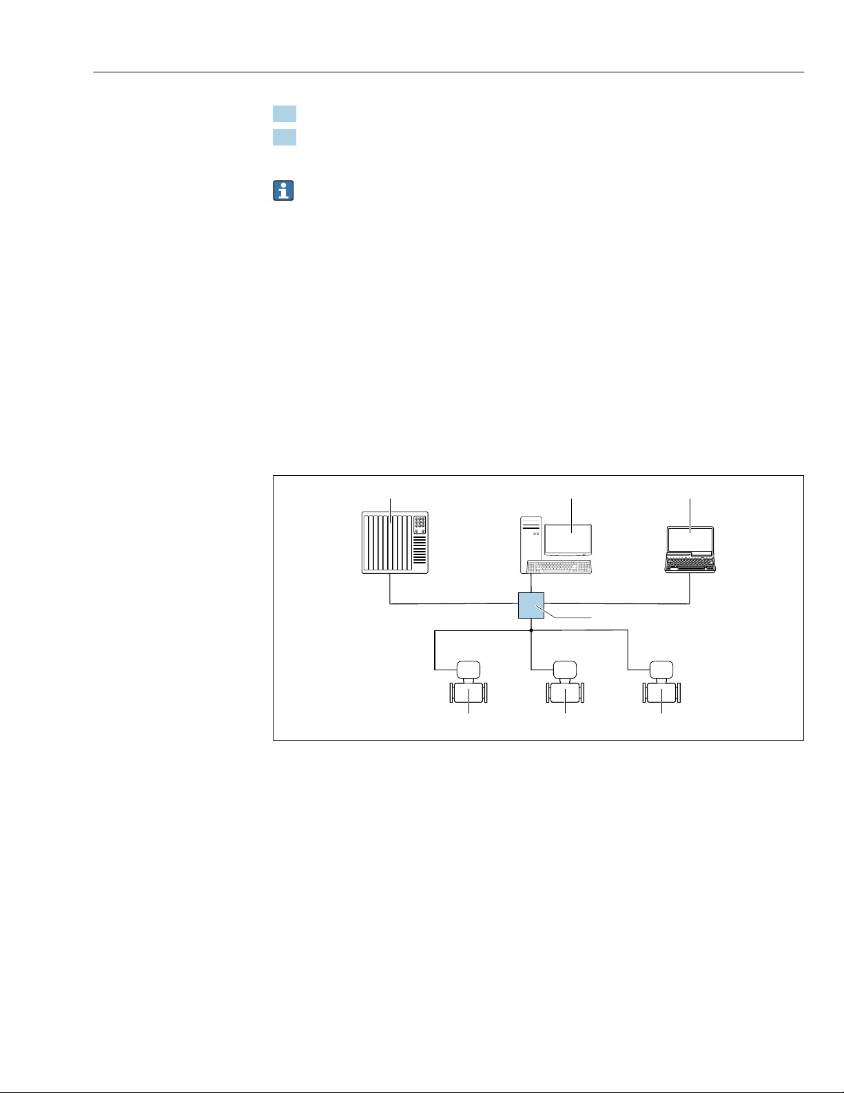
Proline Promass F 300 EtherNet/IP Operation options
4
21 3
5 5 5
2. Close the Web browser.
3. If no longer needed:
Reset modified properties of the Internet protocol (TCP/IP) → 68.
If communication with the Web server was established via the default IP address
192.168.1.212, DIP switch No. 10 must be reset (from ON → OFF). Afterwards, the IP
address of the device is active again for network communication.
8.5 Access to the operating menu via the operating tool
The structure of the operating menu in the operating tools is the same as for operation via
the local display.
8.5.1 Connecting the operating tool
Via EtherNet/IP network
This communication interface is available in device versions with EtherNet/IP.
Star topology
20 Options for remote operation via EtherNet/IP network: star topology
1 Automation system, e.g. "RSLogix" (Rockwell Automation)
2 Workstation for measuring device operation: with Custom Add-On Profile for "RSLogix 5000" (Rockwell
3 Computer with Web browser (e.g. Internet Explorer) for accessing the integrated device Web server or
4 Ethernet switch
5 Measuring device
Ring topology
The device is integrated via the terminal connection for signal transmission (output 1) and
the service interface (CDI-RJ45).
A0032078
Automation) or with Electronic Data Sheet (EDS)
computer with operating tool (e.g. FieldCare, DeviceCare) with COM DTM "CDI Communication TCP/IP"
73
Page 74
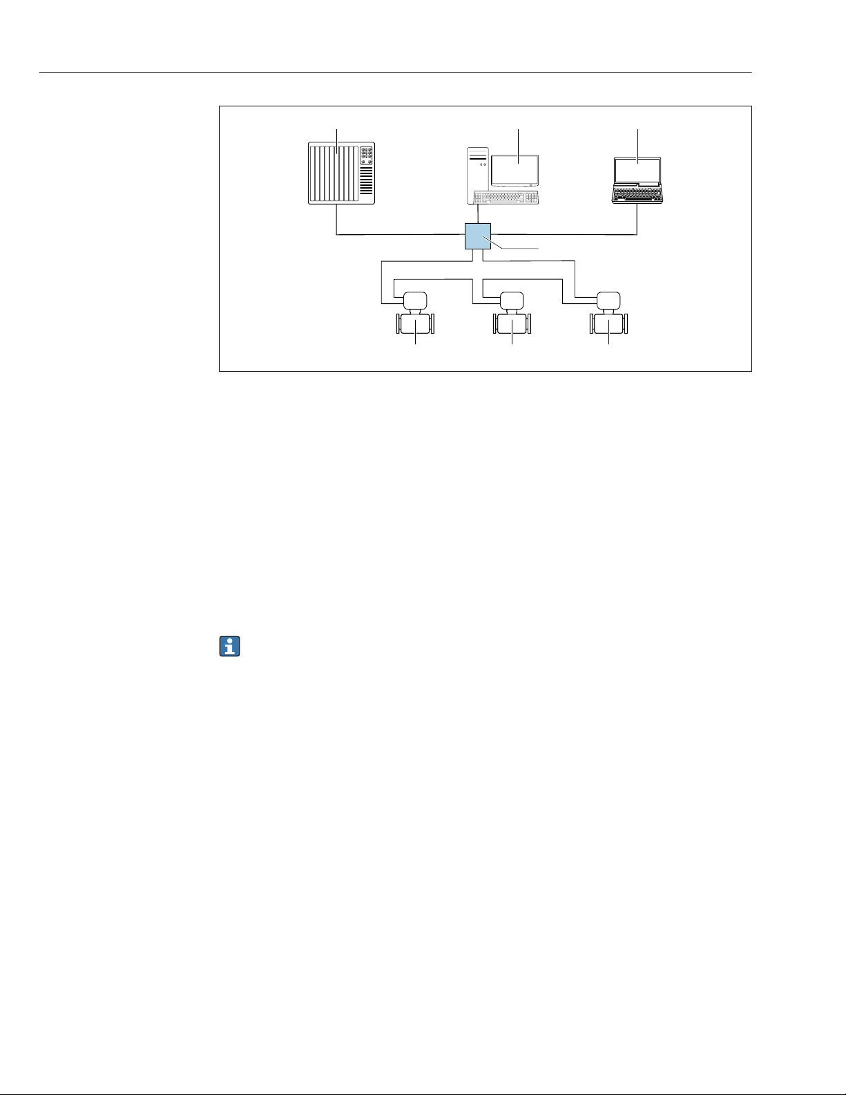
Operation options Proline Promass F 300 EtherNet/IP
4
21 3
5
5 5
A0033725
21 Options for remote operation via EtherNet/IP network: ring topology
1 Automation system, e.g. "RSLogix" (Rockwell Automation)
2 Workstation for measuring device operation: with Custom Add-On Profile for "RSLogix 5000" (Rockwell
Automation) or with Electronic Data Sheet (EDS)
3 Computer with Web browser (e.g. Internet Explorer) for accessing the integrated device Web server or
computer with operating tool (e.g. FieldCare, DeviceCare) with COM DTM "CDI Communication TCP/IP"
4 Ethernet switch
5 Measuring device
Service interface
Via service interface (CDI-RJ45)
A point-to-point connection can be established to configure the device onsite. With the
housing open, the connection is established directly via the service interface (CDI-RJ45) of
the device.
An adapter for RJ45 and the M12 connector is optionally available:
Order code for "Accessories", option NB: "Adapter RJ45 M12 (service interface)"
The adapter connects the service interface (CDI-RJ45) to an M12 connector mounted
in the cable entry. Therefore the connection to the service interface can be established
via an M12 connector without opening the device.
74
Page 75
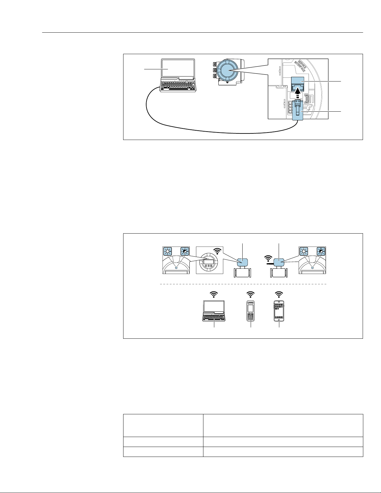
Proline Promass F 300 EtherNet/IP Operation options
2
3
1
213
4
3
4
5 6 7
A0027563
22 Connection via service interface (CDI-RJ45)
1 Computer with Web browser (e.g. Microsoft Internet Explorer, Microsoft Edge) for accessing the integrated
device Web server or with "FieldCare", "DeviceCare" operating tool with COM DTM "CDI Communication TCP/IP"
2 Standard Ethernet connecting cable with RJ45 connector
3 Service interface (CDI-RJ45) of the measuring device with access to the integrated Web server
Via WLAN interface
The optional WLAN interface is available on the following device version:
Order code for "Display; operation", option G "4-line, illuminated, graphic display; touch
control + WLAN"
A0034570
1 Transmitter with integrated WLAN antenna
2 Transmitter with external WLAN antenna
3 LED lit constantly: WLAN reception is enabled on measuring device
4 LED flashing: WLAN connection established between operating unit and measuring device
5 Computer with WLAN interface and Web browser (e.g. Microsoft Internet Explorer, Microsoft Edge) for
accessing the integrated device Web server or with operating tool (e.g. FieldCare, DeviceCare)
6 Mobile handheld terminal with WLAN interface and Web browser (e.g. Microsoft Internet Explorer, Microsoft
Edge) for accessing the integrated device Web server or operating tool (e.g. FieldCare, DeviceCare)
7 Smartphone or tablet
Function WLAN: IEEE 802.11 b/g (2.4 GHz)
• Access point with DHCP server (default setting)
• Network
Encryption WPA2-PSK/AES 128 bit
Configurable WLAN channels 1 to 11
75
Page 76
Operation options Proline Promass F 300 EtherNet/IP
Degree of protection IP67
Available antennas • Internal antenna
• External antenna (optional)
In the event of poor transmission/reception conditions at the place of
installation.
Only one antenna active in each case!
Max. range 50 m (164 ft)
Materials:
External WLAN antenna
• Antenna: ASA plastic (acrylic ester-styrene-acrylonitrile) and nickelplated brass
• Adapter: Stainless steel and nickel-plated brass
• Cable: Polyethylene
• Connector: Nickel-plated brass
• Angle bracket: Stainless steel
Configuring the Internet protocol of the mobile terminal
NOTICE
If the WLAN connection is lost during the configuration, settings made may be lost.
Make sure that the WLAN connection is not disconnected while configuring the device.
‣
NOTICE
In principle, avoid simultaneous access to the measuring device via the service
interface (CDI-RJ45) and the WLAN interface from the same mobile terminal. This
could cause a network conflict.
Only activate one service interface (CDI-RJ45 service interface or WLAN interface).
‣
If simultaneous communication is necessary: configure different IP address ranges, e.g.
‣
192.168.0.1 (WLAN interface) and 192.168.1.212 (CDI-RJ45 service interface).
Preparing the mobile terminal
Enable WLAN reception on the mobile terminal.
‣
Establishing a connection from the mobile terminal to the measuring device
1. In the WLAN settings of the mobile terminal:
Select the measuring device using the SSID (e.g. EH_Promass_300_A802000).
2. If necessary, select the WPA2 encryption method.
3. Enter the password: serial number of the measuring device ex-works (e.g.
L100A802000).
LED on display module flashes: it is now possible to operate the measuring device
with the Web browser, FieldCare or DeviceCare.
The serial number can be found on the nameplate.
To ensure the safe and swift assignment of the WLAN network to the measuring
point, it is advisable to change the SSID name. It should be possible to clearly assign
the new SSID name to the measuring point (e.g. tag name) because it is displayed as
the WLAN network.
76
Disconnecting
After configuring the device:
‣
Terminate the WLAN connection between the operating unit and measuring device.
Page 77
Proline Promass F 300 EtherNet/IP Operation options
8.5.2 FieldCare
Function scope
FDT-based plant asset management tool from Endress+Hauser. It can configure all smart
field devices in a system and helps you manage them. By using the status information, it is
also a simple but effective way of checking their status and condition.
Access is via:
• CDI-RJ45 service interface → 74
• WLAN interface→ 75
Typical functions:
• Configuring parameters of transmitters
• Loading and saving device data (upload/download)
• Documentation of the measuring point
• Visualization of the measured value memory (line recorder) and event logbook
For additional information about FieldCare, see Operating Instructions BA00027S
and BA00059S
Source for device description files
See information → 79
Establishing a connection
1. Start FieldCare and launch the project.
2. In the network: Add a device.
The Add device window opens.
3. Select the CDI Communication TCP/IP option from the list and press OK to confirm.
4. Right-click CDI Communication TCP/IP and select the Add device option in the
context menu that opens.
5. Select the desired device from the list and press OK to confirm.
The CDI Communication TCP/IP (Configuration) window opens.
6. Enter the device address in the IP address field: 192.168.1.212 and press Enter to
confirm.
7. Establish the online connection to the device.
For additional information, see Operating Instructions BA00027S and BA00059S
77
Page 78
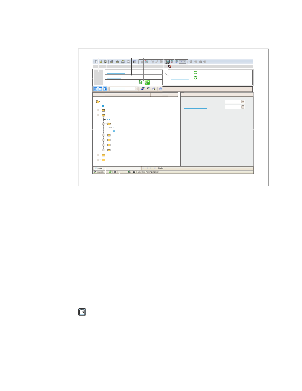
Operation options Proline Promass F 300 EtherNet/IP
6
5
32
1
Xxxxxx/…/…/
7
P
P
+
–
P
–
P
+
+
+
+
+
+
4
8 9
10
11
Xxxxxxx
GoodStatus:
Device tag:
Xxxxxxx
Device name:
Mass flow:
12.34
kg/h
Volume flow:
12.34
m /h³
Mass flow unit:
Volume flow unit:
kg/h
m /h³
Access status tooling
Operation
Setup
Xxxxxx
Mass flow unit
Volume flow unit
Select medium
Device tag
…
…
Advanced setup
Diagnostics
Expert
Maintenance
kg/h
m /h³
Xxxxxx
System units
User interface
1 Header
2 Picture of device
3 Device name
4 Tag name
5 Status area with status signal→ 192
6 Display area for current measured values
7 Edit toolbar with additional functions such as save/restore, event list and create documentation
8 Navigation area with operating menu structure
9 Working area
10 Range of action
11 Status area
8.5.3 DeviceCare
78
Function scope
Tool to connect and configure Endress+Hauser field devices.
The fastest way to configure Endress+Hauser field devices is with the dedicated
"DeviceCare" tool. Together with the device type managers (DTMs) it presents a convenient,
comprehensive solution.
For details, see Innovation Brochure IN01047S
Source for device description files
See information → 79
A0021051-EN
Page 79
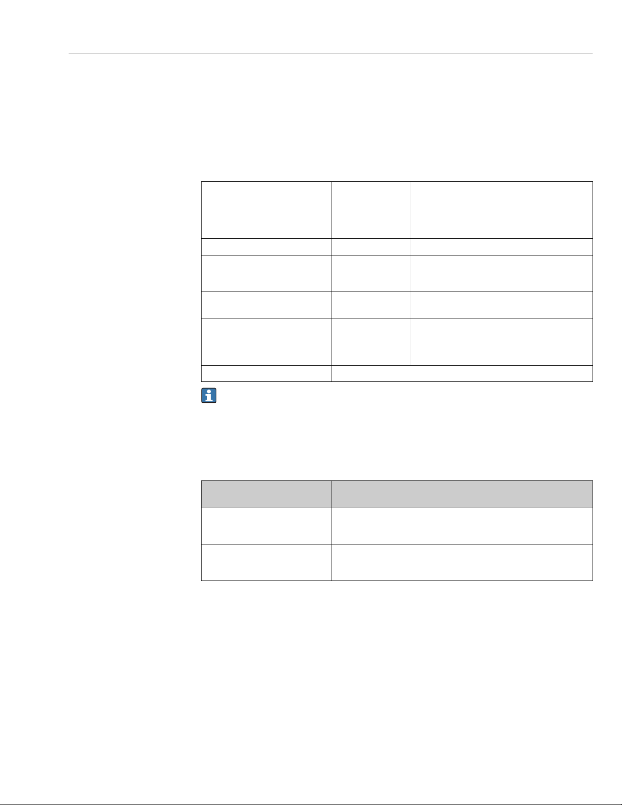
Proline Promass F 300 EtherNet/IP System integration
9 System integration
9.1 Overview of device description files
9.1.1 Current version data for the device
Firmware version 01.00.zz • On the title page of the Operating Instructions
• On the transmitter nameplate
• Firmware version
Diagnostics → Device information → Firmware
version
Release date of firmware version 10.2017 ---
Manufacturer ID 0x11 Manufacturer ID
Diagnostics → Device information → Manufacturer
ID
Device type ID 0x103B Device type
Diagnostics → Device information → Device type
Device revision • Major revision 1
• Minor revision 1
Device profile Generic device (product type: 0x2B)
• On the transmitter nameplate
• Device revision
Diagnostics → Device information → Device
revision
For an overview of the different firmware versions for the device → 215
9.1.2 Operating tools
The suitable device description file for the individual operating tools is listed in the table
below, along with information on where the file can be acquired.
Operating tool via
Service interface (CDI)
FieldCare • www.endress.com → Download Area
DeviceCare • www.endress.com → Download Area
Sources for obtaining device descriptions
• CD–ROM (contact Endress+Hauser)
• DVD (contact Endress+Hauser)
• CD–ROM (contact Endress+Hauser)
• DVD (contact Endress+Hauser)
79
Page 80
System integration Proline Promass F 300 EtherNet/IP
9.2 Overview of system files
System files Version Description How to acquire
Electronic Data
Sheet (EDS
system file)
Add-on Profile
Level 3
2.1 Certified in accordance with the
following ODVA guidelines:
• Conformance test
• Performance test
• PlugFest
Embedded EDS Support (File Object
0x37)
• Major
revision 1
• Minor
revision 1
System file for "Studio 5000"
software (Rockwell Automation)
• www.endress.com → DownloadArea
• EDS system file integrated in the
device: can be downloaded via
the Web browser
www.endress.com → Download-
Area
9.3 Integrating the measuring device in the system
A detailed description of how to integrate the device into an automation system (e.g.
from Rockwell Automation) is available as a separate document: www.endress.com →
Select country → Automation → Digital communication → Fieldbus device
integration → EtherNet/IP
Protocol-specific data → 230.
9.4 Cyclic data transmission
Cyclic data transmission when using the device master file (GSD).
9.4.1 Block model
The block model shows which input and output data the measuring device makes available
for implicit messaging. Cyclical data exchange is performed using an EtherNet/IP scanner,
e.g. a distributed control system etc.
Measuring device Control system
Transducer
Block
Input Assembly Fix
(Assem100) 44 byte
Mass flow fixed input
assembly
(Assem106) 32 byte
Volume flow fixed input
assembly
(Assem107) 62 byte
Concentration fixed input
assembly
(Assem109) 66 byte
API Referenced corrections
fixed input assembly
(Assem110) 64 byte
Water cut % fixed input
assembly
(Assem111) 80 byte
1)
2)
2)
→ 83
→ 84
→ 84
→ 84
→ 85
→ 85
Permanently assigned
input group
Permanently assigned
input group
Permanently assigned
input group
Permanently assigned
input group
Permanently assigned
input group
Permanently assigned
input group
→
→
→
→
→
→
EtherNet/IP
80
Page 81
Proline Promass F 300 EtherNet/IP System integration
Heartbeat monitoring
fixed input assembly
(Assem112) 96 byte
Input assembly custom
(Assem101) 88 byte
Output assembly fix
(Assem102) 54 byte
Config assembly
(Assem104) 2709 byte
1) Only available with the Concentration application package.
2) Only available with the Petroleum application package.
3) Only available with the Heartbeat Verification application package.
3)
→ 86
→ 86
→ 87
→ 89
Permanently assigned
input group
Configurable
input group
Permanently assigned
output group
Permanently assigned
configuration
→
→
←
→
81
Page 82
System integration Proline Promass F 300 EtherNet/IP
9.4.2 Input and output groups
Possible configurations
Configuration 1: Exclusive Owner Multicast
Input Assembly Fix Instance Size (byte) Min. RPI (ms)
Input Assembly Configurable Configuration 0 x 64 398 –
Output Assembly Fix O → T Configuration 0 x 66 64 5
Input Assembly Fix T → O Configuration 0 x 64 44 5
Configuration 2: Input Only Multicast
Input Assembly Fix Instance Size (byte) Min. RPI (ms)
Input Assembly Configurable Configuration 0 x 68 398 –
Output Assembly Fix O → T Configuration 0 x C7 – –
Input Assembly Fix T → O Configuration 0 x 64 44 5
Configuration 3: Exclusive Owner Multicast
Input Assembly Configurable Instance Size (byte) Min. RPI (ms)
Input Assembly Configurable Configuration 0 x 68 398 –
Output Assembly Fix O → T Configuration 0 x 66 64 5
Input Assembly Fix T → O Configuration 0 x 65 88 5
Configuration 4: Input Only Multicast
Input Assembly Configurable Instance Size (byte) Min. RPI (ms)
Input Assembly Configurable Configuration 0 x 68 398 –
Output Assembly Fix O → T Configuration 0 x C7 – –
Input Assembly Fix T → O Configuration 0 x 64 88 5
Configuration 5: Exclusive Owner Multicast
Input Assembly Fix Instance Size (byte) Min. RPI (ms)
Input Assembly Configurable Configuration 0 x 69 – –
Output Assembly Fix O → T Configuration 0 x 66 64 5
Input Assembly Fix T → O Configuration 0 x 64 44 5
82
Configuration 6: Input Only Multicast
Input Assembly Fix Instance Size (byte) Min. RPI (ms)
Input Assembly Configurable Configuration 0 x 69 – –
Output Assembly Fix O → T Configuration 0 x C7 – –
Input Assembly Fix T → O Configuration 0 x 65 44 5
Page 83
Proline Promass F 300 EtherNet/IP System integration
Configuration 7: Exclusive Owner Multicast
Input Assembly Configurable Instance Size (byte) Min. RPI (ms)
Input Assembly Configurable Configuration 0 x 69 – –
Output Assembly Fix O → T Configuration 0 x 66 64 5
Input Assembly Fix T → O Configuration 0 x 64 88 5
Configuration 8: Input Only Multicast
Input Assembly Configurable Instance Size (byte) Min. RPI (ms)
Input Assembly Configurable Configuration 0 x 69 – –
Output Assembly Fix O → T Configuration 0 x C7 – –
Input Assembly Fix T → O Configuration 0 x 65 88 5
Possible connections
No. #1 #2 #3 #4 #5 #6 #7 #8 #9
Number of connections 1 1 1 1 1 1 1 1 1
Input assembly fixed (Assem100) X
Mass flow fixed input assembly
(Assem106)
Volume flow fixed input assembly
(Assem107)
Input assembly custom (Assem101) X
Viscosity fixed input assembly
(Assem108)
Concentration fixed input assembly
(Assem109)
API Referenced corrections fixed
input assembly (Assem110)
Water cut % fixed input assembly
(Assem111)
Heartbeat monitoring fixed input
assembly (Assem112)
X
X
X
X
X
X
X
Permanently assigned input group
Input assembly fixed (Assem100), 44 byte
Description Byte
1. File header (not visible) 1-4
2. Current diagnosis
3. Mass flow 9-12
4. Volume flow 13-16
5. Corrected volume flow 17-20
6. Temperature 21-24
7. Density 25-28
1)
5-8
83
Page 84
System integration Proline Promass F 300 EtherNet/IP
Description Byte
8. Reference density 29-32
9. Totalizer 1 33-36
10. Totalizer 2 37-40
11. Totalizer 3 41-44
1) Diagnostic information via EtherNet/IP → 93
Mass flow fixed input assembly (Assem106), 32 byte
Description Byte
1. File header (not visible) 1-4
2. Current diagnosis
3. Mass flow 9-12
4. Density 13-16
5. Temperature 17-20
6. Totalizer 1 21-24
7. Mass flow unit 25-26
8. Density unit 27-28
9. Temperature unit 29-30
10. Totalizer 1 unit 31-32
1)
5-8
1) Diagnostic information via EtherNet/IP → 93
Volume flow fixed input assembly (Assem107), 62 byte
Description Byte
1. Mass flow fixed input assembly 1-32
2. Volume flow 33-36
3. Corrected volume flow 37-40
4. Reference density 41-44
5. Totalizer 2 45-48
6. Totalizer 3 49-52
7. Volume flow unit 53-54
8. Corrected volume flow unit 55-56
9. Reference density unit 57-58
10. Totalizer 2 unit 59-60
11. Totalizer 3 unit 61-62
Concentration fixed input assembly (Assem109), 66 byte
Description Byte
1. Mass flow fixed input assembly 1-32
2. Target mass flow 33-36
1)
84
Page 85
Proline Promass F 300 EtherNet/IP System integration
Description Byte
3. Carrier mass flow 37-40
4. Target volume flow 41-44
5. Carrier volume flow 45-48
6. Target corrected volume flow 49-52
7. Carrier corrected volume flow 53-56
8. Concentration 57-60
9. Volume flow unit 61-62
10. Corrected volume flow unit 63-64
11. Concentration unit 65-66
1) Only available with the Concentration application package.
API Referenced corrections fixed input assembly (Assem110), 60 byte
Description Byte
1. Mass flow fixed input assembly 1-32
2. Alternative reference density 33-36
3. GSV flow 37-40
4. Alternative GSV flow 41-44
5. NSV flow 45-48
6. Alternative NSV flow 49-52
7. S&W volume flow 53-56
8. Volume flow unit 57-58
9. Reference density unit 59-60
1) Only available with the Petroleum application package.
Water cut % fixed input assembly (Assem111), 76 byte
Description Byte
1. Mass flow fixed input assembly 1-32
2. Oil density 33-36
3. Water density 37-40
4. Water cut % 41-44
5. Oil mass flow 45-48
6. Water mass flow 49-52
7. Oil volume flow 53-56
8. Water volume flow 57-60
9. Oil corrected volume flow 61-64
10. Water corrected volume flow 65-68
11. Volume flow unit 69-70
12. Corrected volume flow unit 71-72
1)
1)
85
Page 86
System integration Proline Promass F 300 EtherNet/IP
Description Byte
13. Oil density unit 73-74
14. Water density unit 75-76
1) Only available with the Petroleum application package
Heartbeat monitoring fixed input assembly (Assem112), 100 byte
Description Byte
1. Mass flow fixed input assembly 1-32
2. Signal asymmetry 33-36
3. Oscillation frequency 0 37-40
4. Oscillation frequency 1 41-44
5. Oscillation amplitude 0 45-48
6. Oscillation amplitude 1 49-52
7. Oscillation damping 0 53-56
8. Oscillation damping 1 57-60
9. Tube damping fluctuation 0 61-64
10. Tube damping fluctuation 1 65-68
11. Exciter current 0 69-72
12. Exciter current 1 73-76
13. HBSI 77-80
14. Frequency fluctuation 0 81-84
15. Frequency fluctuation 1 85-88
16. Electronic temperature 89-92
17. Carrier pipe temperature 93-96
18. Verification status 97-98
19. Verification results 99-100
1)
86
1) Only available with the Heartbeat Verification application package.
Configurable input group
Input assembly custom (Assem101), 88 byte
Description Format
1. - 10. Input values 1 to 10 Real
11. - 20. Input values 11 to 20 Double integer
Page 87
Proline Promass F 300 EtherNet/IP System integration
Possible input values
Possible input values 1 to 10:
• Off
• Mass flow
• Volume flow
• Corrected volume flow
• Target mass flow
• Carrier mass flow
• Target volume flow
• Carrier volume flow
1)
1)
1)
1)
• Target corrected volume flow
• Carrier corrected volume flow
• Density
• Reference density
• Concentration
1)
1) Only available with the Concentration application package.
2) Only available with the Heartbeat Verification application package.
3) Only available with the Petroleum application package.
Possible input values 11 to 20:
• Off
• Actual diagnostics
• Previous diagnosis
• Mass flow unit
• Volume flow unit
• Corrected volume flow unit
• Temperature
• Carrier tube temperature
• Electronic temperature
• Oscillation frequency 0
• Oscillation frequency 1
• Oscillation amplitude 0
• Oscillation amplitude 1
• Frequency fluctuation 0
1)
• Frequency fluctuation 1
1)
• Oscillation damping 0
• Oscillation damping 1
• Tube damping fluctuation 0
• Tube damping fluctuation 1
• Signal asymmetry
• Temperature unit
• Density unit
• Reference density unit
• Concentration unit
• Current unit
2)
2)
2)
2)
• Exciter current 0
• Exciter current 1
2)
• Monitoring of exciter current 0
• Monitoring of exciter current 1
2)
• HBSI
• Totalizer 1
• Totalizer 2
• Totalizer 3
• Alternative reference density
• GSV flow
• Alternative GSV flow
• NSV flow
• Alternative NSV flow
• S&W volume flow
3)
3)
3)
3)
3)
2)
3)
• Totalizer 1 unit
• Totalizer 2 unit
• Totalizer 3 unit
• Verification results
• Verification status
• Status zero point adjustment
Permanently assigned output group
Output assembly fix (Assem102), 54 byte
Description (format) Byte Bit Value
1. Totalizer 1 1 0
2. Totalizer 2 1
3. Totalizer 3 2
4. Verification 3
5. Concentration of medium type 4
6. Compensation, pressure 5
7. Reference density compensation 6
8. Compensation, temperature 7
9. S&W correction value % 2 0
10. Water cut % 1
11. Flow override 2
12. Zero point adjustment 3
13. Not used 4
14. Not used 5
15. Not used 6
16. Not used 7
• 0: Enable
• 1: Disable
• 0: Enable
• 1: Disable
87
Page 88
System integration Proline Promass F 300 EtherNet/IP
Description (format) Byte Bit Value
17. Not used 3-4 16 –
18. Control totalizer 1 (integer) 5-6 16 • 32226 (0): Add
19. Control totalizer 2 (integer) 7-8 16
20. Control totalizer 3 (integer) 9-10 16
21. Start verification (integer) 11-12 16 • 32823 (0): Cancel
22. Select concentration of medium type 13-14 16 • 3062 (0) : Aqueous Fructose
23. Not used 15-16 16 –
24. External pressure (real) 17-20 32 Data format:
25. External pressure unit (integer) 21-22 16 • 1610 (11): Pa a
26. Not used 23-24 16 –
27. External reference density (real) 25-28 32 Data format:
• 32490 (1): Reset and stop
• 32228 (2): Default value and stop
• 198 (3): Reset and add
• 199 (4): Default value and add
• 32928 (3): Stop
• 33158 (1): Start
• 3063 (0) : Aqueous Glucose
• 3068 (0) : Aqueous Hydrochloric Acid
• 3077 (0) : Aqueous Hydrogen
Peroxide
• 3065 (0) : Aqueous Sucrose
• 3064 (0) : Aqueous Invert Sugar
• 3069 (0) : Aqueous Nitric Acid
• 3070 (0) : Aqueous Phosphoric Acid
• 3075 (0) : Aqueous Potassium
Hydroxide
• 3071 (0) : Aqueous Sodium Hydroxide
• 3060 (0) : Ethanol Water
• 3061 (0) : Methanol Water
• 3066 (0) : Ammonium Nitrate In
Water
• 3067 (0) : Ferric Chloride In Water
• 3073 (0) : High Fructose Corn Syrup
42
• 3074 (0) : High Fructose Corn Syrup
55
• 3072 (0) : High Fructose Corn Syrup
90
• 3092 (0) : Percent Volume / Percent
Mass
• 3081 (0) : Wort
• 3082 (0) : Coef Set 1
• 3083 (0) : Coef Set 2
• 3084 (0) : Coef Set 3
Byte 1-4: External pressure
Floating-point number (IEEE754)
• 1616 (12): kPa a
• 1614 (237): MPa a
• 1137 (7): bar
• 1611 (240): Pa g
• 1617 (240): kPa a
• 1615 (240): MPa a
• 32797 (7): bar g
• 1142 (6): psi a
• 1143 (240): psi g
Byte 1-4: External ref. density
Floating-point number (IEEE754)
88
Page 89
Proline Promass F 300 EtherNet/IP System integration
Description (format) Byte Bit Value
28. External reference density unit (integer) 29-30 16 • 32840 (240): kg/Nm
• 32841 (240): kg/Nl
• 32842 (240): g/Scm
• 32843 (240): kg/Scm
• 32844 (240): lb/Sft
29. Not used 31-32 16 –
30. External temperature (real) 33-36 32 Data format:
Byte 1-4: External temperature
Floating-point number (IEEE754)
31. External temperature unit (integer) 37-38 16 • 1001 (32): °C
• 1002 (33): °F
• 1000 (35): K
• 1003 (34): °R
32. Not used 39-40 16 –
33. External value % S&W (real) 41-44 32 Data format:
Byte 1-4: External value, % S&W
Floating-point number (IEEE754)
34. External value, water cut % (real) 45-48 32 Data format:
Byte 1-4: External value, water cut %
Floating-point number (IEEE754)
35 Flow override monitoring 49-50 16 • 33004 (0): Off
• 33006 (1): On
36 Zero point adjustment monitoring 51-52 16 • 32823 (0): Cancel
• 33242 (0): Active
• 248 (0): Error zero point adjustment
• 33158 (1): Start
3
3
3
3
Permanently assigned configuration group
Config assembly (Assem104), 2704 byte
Description (format) Bits Byte Offset
1. None 32 4 0
2. Parameter 36 – Write protection 8 1 4
3. None 8 1 5
4. Parameter 87 System units Mass flow unit 16 2 6
5. Parameter 86 System units Mass unit 16 2 8
6. Parameter 93 System units Volume flow unit 16 2 10
7. Parameter 92 System units Volume unit 16 2 12
8. Parameter 80 System units Corrected volume flow unit 16 2 14
9. Parameter 79 System units Corrected volume unit 16 2 16
10. Parameter 81 System units Density unit 16 2 18
11. Parameter 89 System units Reference density unit 16 2 20
12. Parameter 91 System units Temperature unit 16 2 22
13. None 16 2 24
14. Parameter 88 System units Press. eng. unit 16 2 26
15. Parameter 85 System units Kinematic viscosity unit 16 2 28
89
Page 90

System integration Proline Promass F 300 EtherNet/IP
Description (format) Bits Byte Offset
16. Parameter 84 System units Dynamic viscosity unit 16 2 30
17. Parameter 78 System units Concentration unit 16 2 32
18. Parameter 82 System units Oil density unit 16 2 34
19. Parameter 83 System units Water density unit 16 2 36
20. Parameter 90 System units Water reference density unit 16 2 38
21. None 32 4 40
22. None 16 2 44
23. Parameter 224 – Enter access code 16 2 46
24. Parameter 94 Totalizer 1 Assign process variable 16 2 48
25. Parameter 106 Totalizer 1 Unit totalizer 16 2 50
26. Parameter 103 Totalizer 1 Totalizer operation mode 16 2 52
27. Parameter 100 Totalizer 1 Failure mode 16 2 54
28. Parameter 244 Totalizer operation Preset value tot. 1 32 4 56
29. Parameter 97 Totalizer operation Control totalizer 1 16 2 60
30. Parameter 95 Totalizer 2 Assign process variable 16 2 62
31. Parameter 107 Totalizer 2 Unit totalizer 16 2 64
32. Parameter 104 Totalizer 2 Totalizer operation mode 16 2 66
33. Parameter 101 Totalizer 2 Failure mode 16 2 68
34. Parameter 98 Totalizer operation Control totalizer 2 16 2 70
35. Parameter 245 Totalizer operation Preset value tot. 2 32 4 72
36. Parameter 96 Totalizer 3 Assign process variable 16 2 76
37. Parameter 108 Totalizer 3 Unit totalizer 16 2 78
38. Parameter 105 Totalizer 3 Totalizer operation mode 16 2 80
39. Parameter 102 Totalizer 3 Failure mode 16 2 82
40. Parameter 246 Totalizer operation Preset value tot. 3 32 4 84
41. Parameter 99 Totalizer operation Control totalizer 3 16 2 88
42. Parameter 16 Configurable input assembly Input assembly position 1 16 2 90
43. Parameter 27 Configurable input assembly Input assembly position 2 16 2 92
44. Parameter 29 Configurable input assembly Input assembly position 3 16 2 94
45. Parameter 30 Configurable input assembly Input assembly position 4 16 2 96
46. Parameter 31 Configurable input assembly Input assembly position 5 16 2 98
47. Parameter 32 Configurable input assembly Input assembly position 6 16 2 100
48. Parameter 33 Configurable input assembly Input assembly position 7 16 2 102
49. Parameter 34 Configurable input assembly Input assembly position 8 16 2 104
50. Parameter 35 Configurable input assembly Input assembly position 9 16 2 106
51. Parameter 17 Configurable input assembly Input assembly position 10 16 2 108
52. Parameter 18 Configurable input assembly Input assembly position 11 16 2 110
53. Parameter 19 Configurable input assembly Input assembly position 12 16 2 112
54. Parameter 20 Configurable input assembly Input assembly position 13 16 2 114
55. Parameter 21 Configurable input assembly Input assembly position 14 16 2 116
90
Page 91

Proline Promass F 300 EtherNet/IP System integration
Description (format) Bits Byte Offset
56. Parameter 22 Configurable input assembly Input assembly position 15 16 2 118
57. Parameter 23 Configurable input assembly Input assembly position 16 16 2 120
58. Parameter 24 Configurable input assembly Input assembly position 17 16 2 122
59. Parameter 25 Configurable input assembly Input assembly position 18 16 2 124
60. Parameter 26 Configurable input assembly Input assembly position 19 16 2 126
61. Parameter 28 Configurable input assembly Input assembly position 20 16 2 128
62. Parameter 38 Sensor adjustment Flow direction 16 2 130
63. Parameter 40 Process parameter Flow override 16 2 132
64. Parameter 37 Low flow cut off Assign process variable 16 2 134
65. Parameter 39 Empty pipe detection Assign process variable 16 2 136
66. Parameter 41 Corrected volume flow calculation Corrected volume flow calculation 16 2 138
67. Parameter 188 Low flow cut off On value low flow cut off 32 4 140
68. Parameter 187 Low flow cut off Off value low flow cutoff 32 4 144
69. Parameter 209 Low flow cut off Pressure shock suppression 32 4 148
70. Parameter 191 Empty pipe detection Low value partial filled pipe detection 32 4 152
71. Parameter 189 Partially filled pipe detection High value partial filled pipe detection 32 4 156
72. Parameter 190 Empty pipe detection Response time part. filled pipe detect. 32 4 160
73. Parameter 182 Corrected volume flow calculation Fixed reference density 32 4 164
74. Parameter 186 Corrected volume flow calculation Linear expansion coefficient 32 4 168
75. Parameter 211 Corrected volume flow calculation Square expansion coefficient 32 4 172
76. Parameter 210 Corrected volume flow calculation Reference temperature 32 4 176
77. Parameter 183 Process parameter Flow damping 32 4 180
78. Parameter 184 Process parameter Density damping 32 4 184
79. Parameter 185 Process parameter Temperature damping 32 4 188
80. Parameter 5 External compensation Pressure compensation 16 2 192
81. Parameter 6 External compensation Temperature mode 16 2 194
82. Parameter 2 Medium selection Select medium 16 2 196
83. Parameter 3 Medium selection Select gas type 16 2 198
84. Parameter 119 External compensation Pressure value 32 4 200
85. Parameter 133 Medium selection Temperature coefficient sound velocity 32 4 204
86. Parameter 128 Medium selection Reference sound velocity 32 4 208
87. Parameter 115 Empty pipe detection Max. damping empty pipe detection 32 4 212
88. Parameter 241 Diagnostic settings Alarm delay 32 4 216
89. Parameter 58 Diagnostic behavior Assign behavior for diagnostic
information 046
90. Parameter 57 Diagnostic behavior Assign behavior for diagnostic
information 140
91. Parameter 59 Diagnostic behavior Assign behavior for diagnostic
information 144
92. Parameter 60 Diagnostic behavior Assign behavior for diagnostic
information 374
8 1 220
8 1 221
8 1 222
8 1 223
91
Page 92
System integration Proline Promass F 300 EtherNet/IP
Description (format) Bits Byte Offset
93. Parameter 61 Diagnostic behavior Assign behavior for diagnostic
information 302
94. None 8 1 225
95. Parameter 74 Diagnostic behavior Assign behavior for diagnostic
information 441
96. Parameter 75 Diagnostic behavior Assign behavior for diagnostic
information 442
97. Parameter 76 Diagnostic behavior Assign behavior for diagnostic
information 443
98. Parameter 73 Diagnostic behavior Assign behavior for diagnostic
information 444
99. Parameter 62 Diagnostic behavior Assign behavior for diagnostic
information 830
100. Parameter 63 Diagnostic behavior Assign behavior for diagnostic
information 831
101. Parameter 64 Diagnostic behavior Assign behavior for diagnostic
information 832
102. Parameter 65 Diagnostic behavior Assign behavior for diagnostic
information 833
103. Parameter 66 Diagnostic behavior Assign behavior for diagnostic
information 834
104. Parameter 67 Diagnostic behavior Assign behavior for diagnostic
information 835
105. Parameter 72 Diagnostic behavior Assign behavior for diagnostic
information 862
106. Parameter 68 Diagnostic behavior Assign behavior for diagnostic
information 912
107. Parameter 69 Diagnostic behavior Assign behavior for diagnostic
information 913
108. Parameter 70 Diagnostic behavior Assign behavior for diagnostic
information 944
109. Parameter 71 Diagnostic behavior Assign behavior for diagnostic
information 948
110. None 32 4 246
111. None 16 2 250
112. Parameter 12 Concentration Liquid type 16 2 252
113. None 32 4 254
114. None 16 2 258
115. Parameter 138 Concentration Coefficient A0 32 4 260
116. Parameter 141 Concentration Coefficient A1 32 4 264
117. Parameter 144 Concentration Coefficient A2 32 4 268
118. Parameter 147 Concentration Coefficient A3 32 4 272
119. Parameter 150 Concentration Coefficient A4 32 4 276
120. Parameter 153 Concentration Coefficient B1 32 4 280
121. Parameter 156 Concentration Coefficient B2 32 4 284
122. Parameter 159 Concentration Coefficient B3 32 4 288
8 1 224
16 2 226
16 2 228
16 2 230
16 2 232
8 1 234
8 1 235
8 1 236
8 1 237
8 1 238
8 1 239
16 2 240
8 1 242
8 1 243
8 1 244
8 1 245
92
Page 93
Proline Promass F 300 EtherNet/IP System integration
Description (format) Bits Byte Offset
123. Parameter 162 Concentration Coefficient D1 32 4 292
124. Parameter 165 Concentration Coefficient D2 32 4 296
125. Parameter 168 Concentration Coefficient D3 32 4 300
126. Parameter 171 Concentration Coefficient D4 32 4 304
127. Parameter 55 Petroleum mode 16 2 308
128. Parameter 53 API product group 16 2 310
129. Parameter 54 API table selection 16 2 312
130. None 16 2 314
131. Parameter 237 Thermal expansion coefficient 32 4 316
132. Parameter 220 Oil density sample 32 4 320
133. Parameter 235 Oil temperature sample 32 4 324
134 Parameter 230 Oil pressure sample 32 4 328
135 Parameter 222 Water density sample 32 4 332
136 Parameter 236 Water temperature sample 32 4 336
9.5 Diagnostic information via EtherNet/IP
Status signal No. Short text Value
000 – 0
F 882 Input signal 16777265
F 910 Tubes not oscillating 16777296
F 437 Configuration incompatible 16777312
F 242 Software incompatible 16777319
F 252 Modules incompatible 16777323
F 272 Main electronic failure 16777337
F 270 Main electronic failure 16777340
F 271 Main electronic failure 16777341
F 270 Main electronic failure 16777343
F 270 Main electronic failure 16777344
F 825 Operating temperature 16777352
F 410 Data transfer 16777355
F 273 Main electronic failure 16777368
F 270 Main electronic failure 16777375
F 083 Memory content 16777376
F 270 Main electronic failure 16777377
F 022 Sensor temperature 16777406
F 022 Sensor temperature 16777407
F 833 Electronic temperature too low 16777409
F 832 Electronic temperature too high 16777411
93
Page 94

System integration Proline Promass F 300 EtherNet/IP
Status signal No. Short text Value
F 834 Process temperature too high 16777413
F 835 Process temperature too low 16777414
F 270 Main electronic failure 16777428
F 022 Sensor temperature 16777429
F 022 Sensor temperature 16777430
F 062 Sensor connection 16777435
F 062 Sensor connection 16777436
F 311 Electronic failure 16777441
F 273 Main electronic failure 16777445
F 082 Data storage 16777447
F 190 Special event 2 16777450
F 273 Main electronic failure 16777483
F 390 Special event 3 16777490
F 062 Sensor connection 16777491
F 062 Sensor connection 16777492
F 992 Special event 13 16777503
F 590 Special event 4 16777508
F 990 Special event 5 16777509
F 991 Special event 9 16777510
F 591 Special event 8 16777511
F 391 Special event 7 16777512
F 191 Special event 6 16777513
F 262 Module connection 16777545
F 537 Configuration 16777546
F 201 Device failure 16777547
F 192 Special event 10 16777552
F 392 Special event 11 16777553
F 592 Special event 12 16777554
F 382 Data storage 16777581
F 383 Memory content 16777582
F 283 Memory content 16777583
F 144 Measuring error too high 16777671
C 411 Up-/download active 33554536
C 411 Up-/download active 33554537
C 411 Up-/download active 33554540
C 484 Simulation failure mode 33554576
C 485 Simulation measured variable 33554579
C 453 Flow override 33554580
C 833 Electronic temperature too low 33554625
C 832 Electronic temperature too high 33554627
94
Page 95

Proline Promass F 300 EtherNet/IP System integration
Status signal No. Short text Value
C 834 Process temperature too high 33554629
C 835 Process temperature too low 33554630
C 992 Special event 13 33554719
C 192 Special event 10 33554768
C 392 Special event 11 33554769
C 592 Special event 12 33554770
C 495 Simulation diagnostic event 33554782
C 302 Device verification active 33554926
M 438 Dataset 67108970
M 833 Electronic temperature too low 67109057
M 832 Electronic temperature too high 67109059
M 834 Process temperature too high 67109061
M 835 Process temperature too low 67109062
M 311 Electronic failure 67109090
M 992 Special event 13 67109151
M 192 Special event 10 67109200
M 392 Special event 11 67109201
M 592 Special event 12 67109202
S 825 Operating temperature 134217861
S 825 Operating temperature 134217863
S 842 Process limit 134217873
S 862 Partly filled pipe 134217874
S 830 Sensor temperature too high 134217920
S 833 Electronic temperature too low 134217921
S 831 Sensor temperature too low 134217922
S 832 Electronic temperature too high 134217923
S 912 Medium inhomogeneous 134217924
S 834 Process temperature too high 134217925
S 835 Process temperature too low 134217926
S 046 Sensor limit exceeded 134217928
S 046 Sensor limit exceeded 134217930
S 140 Sensor signal 134217932
S 913 Medium unsuitable 134217933
S 274 Main electronic failure 134217934
S 274 Main electronic failure 134217935
S 912 Medium inhomogeneous 134217951
S 912 Inhomogeneous 134218005
S 992 Special event 13 134218015
S 843 Process limit 134218019
S 192 Special event 10 134218064
95
Page 96

System integration Proline Promass F 300 EtherNet/IP
Status signal No. Short text Value
S 392 Special event 11 134218065
S 592 Special event 12 134218066
S 912 Inhomogeneous 134218082
S 948 Tube damping too high 134218088
S 944 Monitoring failed 134218182
I 1089 Power on 268435545
I 1090 Configuration reset 268435546
I 1091 Configuration changed 268435547
I 1110 Write protection switch changed 268435566
I 1111 Density adjust failure 268435567
I 1137 Electronic changed 268435593
I 1151 History reset 268435607
I 1155 Reset electronic temperature 268435611
I 1157 Memory error event list 268435613
I 1185 Display backup done 268435641
I 1186 Restore via display done 268435642
I 1187 Settings downloaded with display 268435643
I 1188 Display data cleared 268435644
I 1189 Backup compared 268435645
I 1209 Density adjustment ok 268435665
I 1221 Zero point adjust failure 268435677
I 1222 Zero point adjustment ok 268435678
I 1256 Display: access status changed 268435712
I 1264 Safety sequence aborted 268435720
I 1335 Firmware changed 268435791
I 1361 Wrong web server login 268435817
I 1397 Fieldbus: access status changed 268435853
I 1398 CDI: access status changed 268435854
I 1444 Device verification passed 268435900
I 1445 Device verification failed 268435901
I 1446 Device verification active 268435902
I 1447 Record application reference data 268435903
I 1448 Application reference data recorded 268435904
I 1449 Recording application ref. data failed 268435905
I 1450 Monitoring off 268435906
I 1451 Monitoring on 268435907
I 1457 Failed: Measured error verification 268435913
I 1459 Failed: I/O module verification 268435915
I 1460 Failed: Sensor integrity verification 268435916
96
Page 97
Proline Promass F 300 EtherNet/IP System integration
Status signal No. Short text Value
I 1461 Failed: Sensor verification 268435917
I 1462 Failed: Sensor electronic module verific. 268435918
97
Page 98

Commissioning Proline Promass F 300 EtherNet/IP
10 Commissioning
10.1 Function check
Before commissioning the measuring device:
Make sure that the post-installation and post-connection checks have been performed.
‣
• "Post-installation check" checklist→ 32
• "Post-connection check" checklist → 49
10.2 Switching on the measuring device
After a successful function check, switch on the measuring device.
‣
After a successful startup, the local display switches automatically from the startup
display to the operational display.
If nothing appears on the local display or a diagnostic message is displayed, refer to
the section on "Diagnostics and troubleshooting" → 184.
10.3 Connecting via FieldCare
• For FieldCare → 74 connection
• For connecting via FieldCare → 77
• For the FieldCare → 78 user interface
10.4 Setting the operating language
Factory setting: English or ordered local language
98
Page 99
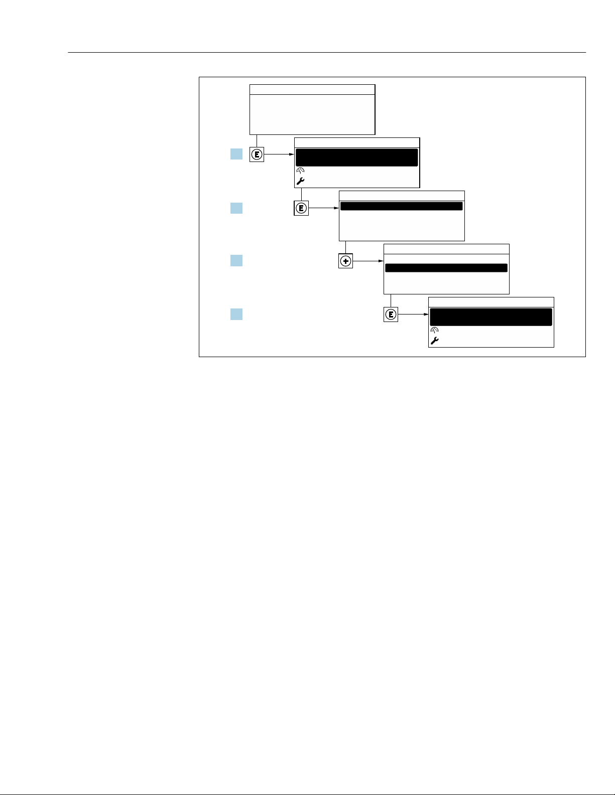
Proline Promass F 300 EtherNet/IP Commissioning
X X X X X X XX X
20.50
Operation
Setup
Main menu
0104-1
Display language
English
Español
Français
Display language
English
Deutsch
Ã
0104-1
Ã
Español
Français
Display language
English
Deutsch
0104-1
Betrieb
Setup
Hauptmenü
Sprache
Deutsch
0104-1
XXXX
1.
2.
3.
4.
23 Taking the example of the local display
10.5 Configuring the measuring device
• The Setup menu with its guided wizards contains all the parameters needed for standard
operation.
• Navigation to the Setup menu
A0029420
99
Page 100
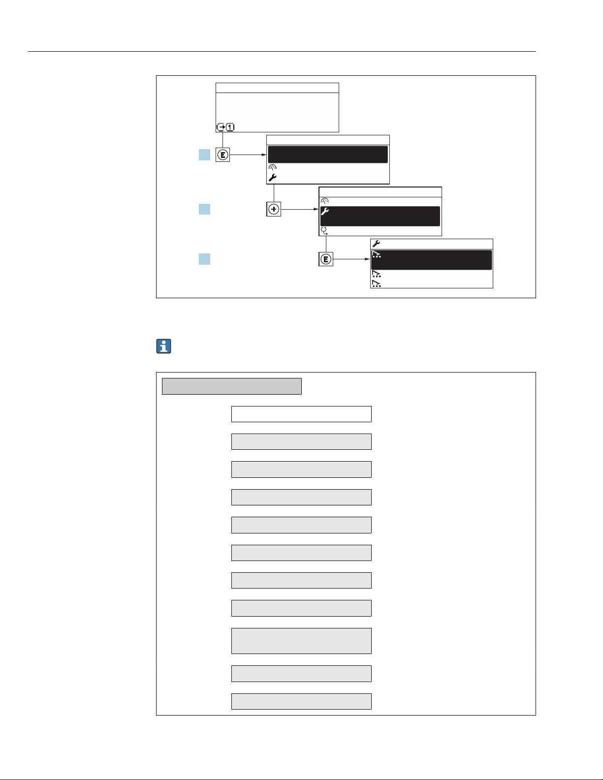
Commissioning Proline Promass F 300 EtherNet/IP
X X X X X X XX X
20.50
0104-1
XXXXXXXXX
XXXXXXXXX
mA
1.
2.
3.
Display/operat.
Setup
Diagnostic
Display/operat.
Setup
Main menu
English
Main menu
Medium selection
/ ../Setup
Display language
A0032222-EN
24 Taking the example of the local display
Depending on the device version, not all submenus and parameters are available in
every device. The selection can vary depending on the order code.
Setup
→ 101
→ 101
→ 103
→ 105
→ 107
→ 107
→ 109
→ 109
→ 114
→ 125
→ 128
Device tag
System units
‣
Communication
‣
Medium selection
‣
I/O configuration
‣
Current input 1 to n
‣
Status input 1 to n
‣
Current output 1 to n
‣
Pulse/frequency/switch output
‣
1 to n
Relay output 1 to n
‣
Display
‣
100
 Loading...