

Page 1
Technical
The PowerofKnowHo w
Information
TI 046D/24/ae
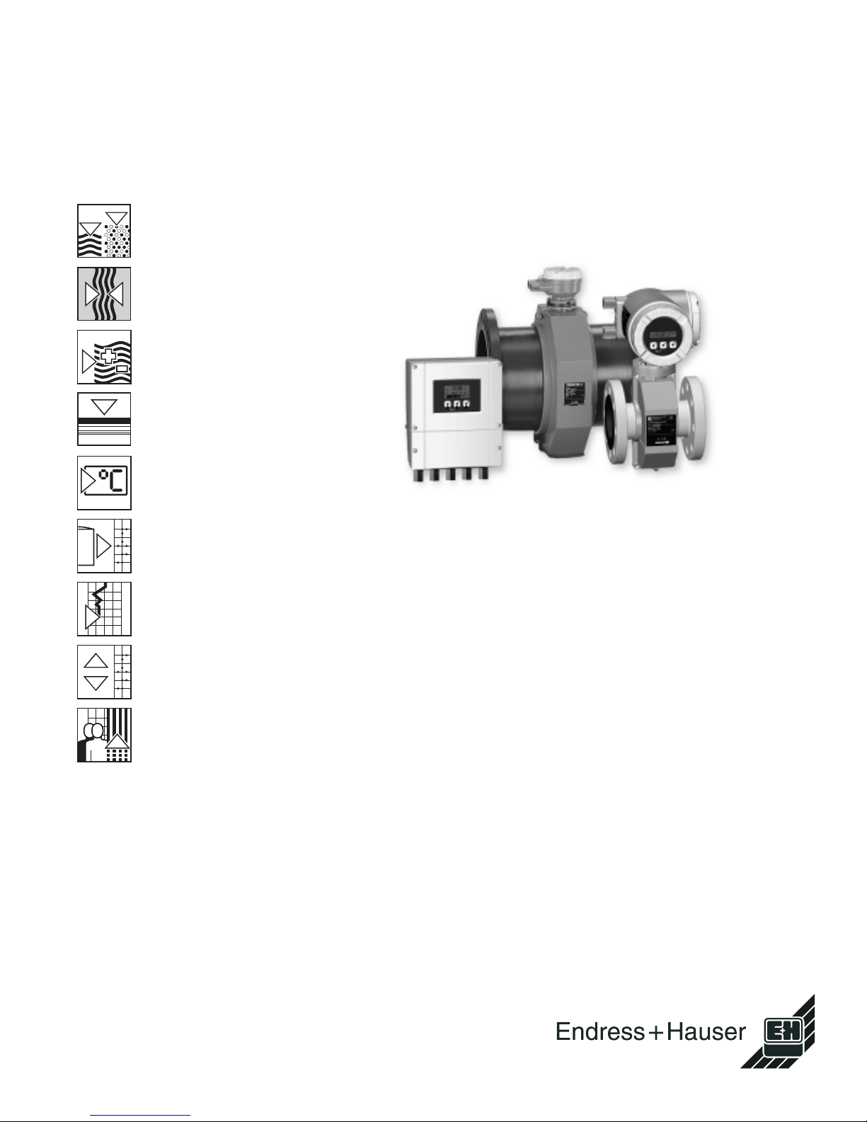
Electromagnetic
Flow Measuring System
PROline promag 50/53 W
Flow measurement in
water or wastewater applications
Features and benefits
• Nominal diameters 1” to 78”
• Hard rubber or polyurethane liners
• PFA for high-temperature applications up to +355°F (+180°C)
• Fitting lengths to ISO and DVGW
• High measuring accuracy for
improved process control:
– Promag 50: ± 0.5%
(option: ± 0.2%)
– Promag 53: ± 0.2%
• Robust field housing, NEMA 4X
(IP 67)
• NEMA 4X (IP 67) wall-mount housing
for straight-forward installation of the
remote version
• NEMA 6P (IP 68) sensor version
• Promag 53 with Touch Control:
operation without opening the
housing - also for explosion proof
applications
• Expandable software packages:
– electrode cleaning
– pulsating flow
• Quick setup menus for straightforward commissioning in the field
• Potable-water approvals:
KTW , WRC, etc.
• Interfaces for integration into all
major process-control systems:
– HART
®
interface as standard
– Promag 50: PROFIBUS-PA
– Promag 53: PROFIBUS-PA/-DP,
FOUNDATION fieldbus
• Explosion proof approval for
installation in Division 1 (FM, CSA,
A TEX, etc.)
Application
All fluids with a minimum conductivity of
≥ 5 µS/cm can be measured:
• Drinking water
• Wastewater
• Wastewater sludge, etc.
A minimum conductivity of ≥ 20 µS/cm is
required for measuring demineralized
water.
Liner specific applications
• Polyurethane lining for applications
with cold water and for slightly
abrasive fluids
• Hard rubber lining for all applications
with water (especially for drinking
water)
Page 2
Function and system design
Promag 50/53 W
Measuring principle
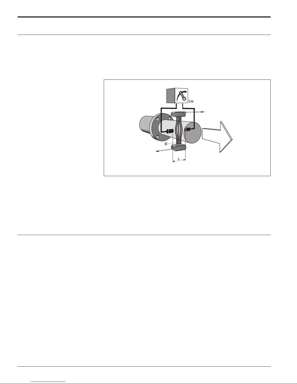
Faraday’s law of induction
states that a voltage is induced in a conductor moving in a
magnetic field.
In electromagnetic measuring, the flowing medium corresponds to the moving
conductor. The induced voltage is proportional to the flow velocity and is detected by
two measuring electrodes and transmitted to the amplifier. Flow volume is computed
on the basis of the pipe’s diameter. The constant magnetic field is generated by a
switched direct current of alternating polarity.
I
V
I
Measuring system
Ue = B · L · v
Q = A · v
U e = induced voltage
B = magnetic induction (magnetic field)
L = electrode gap
v = flow velocity
Q = volume flow
A = pipe cross-section
I = current strength
The measuring system consists of a transmitter and a sensor.
Two versions are available:
• Compact version: transmitter and sensor form a single mechanical unit.
• Remote version: transmitter and sensor are installed separately.
Transmitter:
• Promag 50 (user interface with push buttons for operation, two-line display)
• Promag 53 (“Touch Control” without opening the housing, four-line display)
Sensor:
• Promag W, 1” to 78” (DN 25 to 2000)
2
Endress+Hauser
Page 3

Promag 50/53 W
Input
Measured variable
Measuring range
Operable flow range
Input signal
Output signal
Flow rate (proportional to induced voltage)
Typically v = 0.033 to 33 ft/s (0.01 to 10 m/s) with the specified measur ing accuracy
Over 1000 : 1
Status input (auxiliary input):
U = 3 to 30 V DC, R
Configurable for: totalizer(s) reset, measured-value suppression, error-message
= 5 kΩ, galvanically isolated.
i
reset
Current input (for Promag 53 only):
Active/passive selectable, galvanically isolated, full scale value selectable,
µ
resolution: 3
A
Temperature coefficient: typically 0.003% o.r./°F (0.005% o.r./°C) (o.r = of reading)
Active: 4 to 20 mA, Ri ≤ 150 Ω, U
Passive: 0/4 to 20 mA, Ri ≤ 150 Ω, U
= 24 VDC, short-circuit proof
out
= 30 VDC
max
Output
Promag 50
Current output:
Active/passive selectable, galvanically isolated, time constant selectable
(0.01 to 100 s), full scale value selectable, temperature coefficient: typically
0.003% o.r./°F (0.005% o.r./°C); resolution: 0.5 µA
• active: 0/4 to 20 mA, R
• passive: 4 to 20 mA, max. 30 V DC, Ri ≤ 150 Ω
< 700 Ω (HART®: RL ≥ 250 Ω)
L
Pulse/frequency output:
Passive, open collector, 30 V DC, 250 mA, galvanically isolated.
Frequency output:
pulse width max. 10 s
Pulse output:
full scale frequency 2 to 1000 Hz (f
= 1250 Hz), on/off ratio 1:1,
max
pulse value and pulse polarity selectable, max. pulse width
configurable (0.5 ms to 2 s), maximum pulse frequency selectable
PROFIBUS-PA interface
• PROFIBUS-PA in accordance with EN 50170 Volume 2, IEC 61158-2 (MPB),
galvanically isolated
• Current consumption: 11 mA
• Permissible supply voltage: 9 to 32 V
• FDE (Fault Disconnection Electronic): 0 mA
• Data transmission rate, supported bauderate: 31.25 kBit/s
• Signal encoding: Manchester II
• Function blocks: 1 x Analog Input, 1 x Totalizer
• Output data: Volume flow , Totalizer
• Input data: Positive zero return (ON/OFF), Control totalizer, Value for local display
• Bus address adjustable via DIP switches at the measuring device
Endress+Hauser
3
Page 4

Promag 50/53 W
Promag 53
Current output:
Active/passive selectable, galvanically isolated, time constant selectable
(0.01 to 100 s), full scale value selectable, temperature coefficient: typically
0.003% o.r./°F (0.005% o.r./°C); resolution: 0.5 µA
• active: 0/4 to 20 mA, R
• passive: 4 to 20 mA, max. 30 V DC, Ri ≤ 150 Ω
< 700 Ω (HART®: RL ≥ 250 Ω)
L
Pulse/frequency output:
Active/passive selectable, galvanically isolated (I.S. version: passive only)
• active: 24 V DC, 25 mA (max. 250 mA during 20 ms), R
• passive: open collector, 30 V DC, 250 mA
Frequency output:
full scale frequency 2 to 10,000 Hz (f
on/off ratio 1:1, pulse width max. 10 s
Pulse output:
pulse value and pulse polarity selectable, pulse width configurable
> 100 Ω
L
= 12,500 Hz),
max
(0.05 ms to 2 s), on/off ratio is 1:1 as of a frequency of 1 / (2 x pulse width)
PROFIBUS-DP interface:
• PROFIBUS-DP/PA in accordance with EN 50170 Volume 2, IEC 61158-2 (MPB),
galvanically isolated
• Data transmission rate, supported baudrate: 9.6 kBaud to 12 MBaud
• Automatic data transmission rate recognition
• Signal encoding: NRZ-Code
• Function blocks: 2 x Analog Input, 3 x Totalizer
• Output data: Volume flow, Corrected volume flow, Totalizer 1 to 3
• Input data: Positive zero return (ON/OFF), Totalizer control, Value for local display
• Bus address adjustable via DIP switches at the measuring device
PROFIBUS-PA interface:
• PROFIBUS-PA in accordance with EN 50170 Volume 2, IEC 61158-2 (MPB),
galvanically isolated
• Current consumption: 11 mA
• Permissible supply voltage: 9 to 32 V
• Data transmission rate, supported baudrate: 31.25 kBit/s
• Error current FDE (Fault Disconnection Electronic): 0 mA
• Signal encoding: Manchester II
• Function blocks: 2 x Analog Input, 3 x Totalizer
• Output data: Volume flow, Corrected volume flow, Totalizer 1 to 3
• Input data: Positive zero return (ON/OFF), Totalizer control, Value for local display
• Bus address adjustable via DIP switches at the measuring device
FOUNDATION Fieldbus interface:
• FOUNDATION Fieldbus H1, IEC 61158-2 (MBP), galvanically isolated
• Current consumption: 12 mA
• Permissible supply voltage: 9 to 32 V
• Error current FDE (Fault Disconnection Electronic): 0 mA
• Data transmission rate, supported buadrate: 31.25 kBit/s
• Signal encoding: Manchester II
• Function blocks: 5 x Analog Input, 1 x Discrete Output, 1 x PID
• Output data: Volume flow, Corrected volume flow, Totalizer 1 to 3
• Input data: Positive zero return (ON/OFF), Reset totalizer
• Link Master (LM) functionality is supported
Endress+Hauser4
Page 5

Promag 50/53 W
Signal on alarm
Load
Switching output
Low flow cutoff
Galvanic isolation
• Current output → failure response selectable
• Pulse/frequency output → failure response selectable
• Status output (Promag 50) → non-conductive by fault or power supply failure
• Relay output (Promag 53) → de-energized by fault or power supply failure
See “Output signal”
Status output (Promag 50):
Open collector, max. 30 V DC / 250 mA, galvanically isolated
Configurable for: error messages, Empty Pipe Detection (EPD), flow direction, limit
values
Relay output (Promag 53):
Normally closed (NC or break) or normally open (NO or make) contacts available
(default: relay 1 = NO, relay 2 = NC),
max. 30 V / 0.5 A AC; 60 V / 0.1 A DC, galvanically isolated.
Configurable for: error messages, Empty Pipe Detection (EPD), flow direction, limit
values, batching contacts
Switch points for low flow cutoff are selectable
All circuits for inputs, outputs, and power supply are galvanically isolated from each
other.
Endress+Hauser 5
Page 6
Electrical connection
measuring unit
Power supply
b
a
Promag 50/53 W
−27
f
+26
−25
e
+24
−23
+22
−21
+20
b
d
N (L-)
g
L1 (L+)
2
1
c
a
N (L-)
L1 (L+)
1
222320
21 24
+ − + − + − + −
2
27
26
25
e
f
a
b
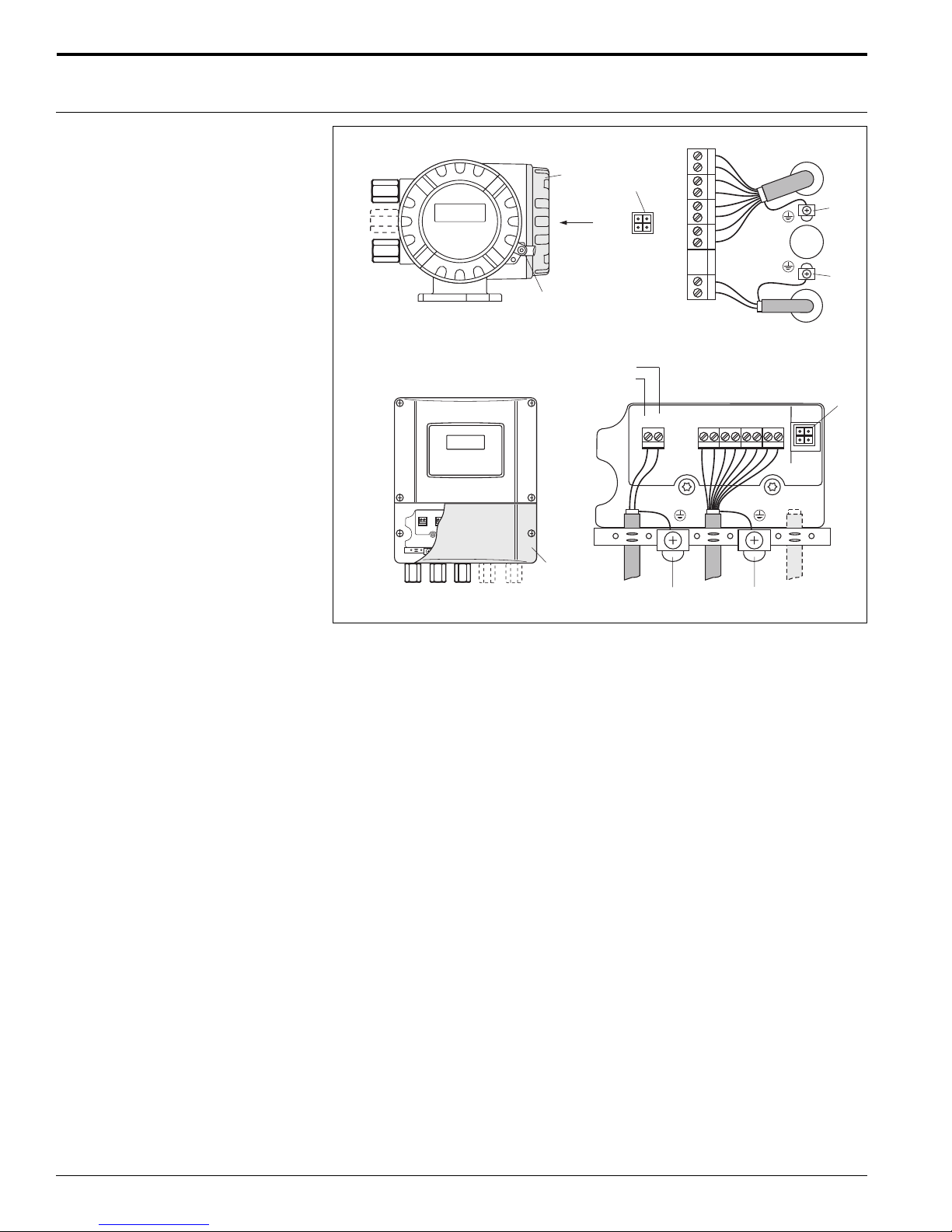
Top: field housing
Bottom: wall-mount housing
a Cable for power supply: 85 to 260 VAC, 20 to 55 VAC, or 16 to 62 VDC; power consumption: 15 VA / 15 W
Terminal No. 1: L1 fo AC, L+ for DC
Terminal No. 2: N for AC, L- for DC
b Signal cable: terminals No. 20 to 27 ´® see Page 8
c Grounding terminal for protective conductor
d Grounding terminal for signal-cable shield
e Service connection for connecting service interface FXA 193 (FieldChec k, ToF T ool-Field Tool Package)
f Cover for wiring compartment
g Cover securing clamp
cda
b
Endress+Hauser6
Page 7
Promag 50/53 W
Electrical connection
Measuring unit (bus communication)
f
DP (A)/PA (–)/FF (–)
DP (B)/PA (+)/FF (+)
b
g
e
a
h
N (L–)
L1 (L+)
Esc
-
+
E
(DGND)
(+5 V)
N (L-)
L1 (L+)
2
1
27
26
25
24
23
22
21
20
2
1
222320 21 242526
27
b
d
g
c
a
(+5 V)
(DGND)
DP (B)/PA (+)/FF (+)
DP (A)/PA (–)/FF (–)
e
f
cd
a
bg
a
g
b
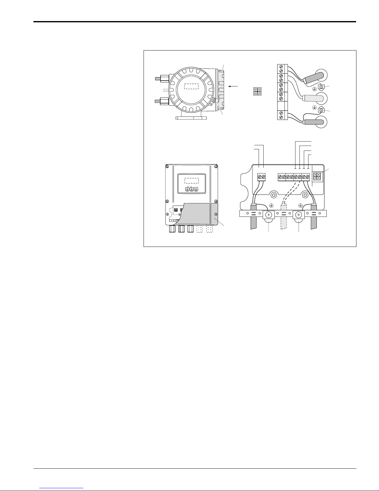
T op: Field housing
Bottom: Wall-mount housing
a Cable for power supply: 85 to 260 VAC, 20 to 55 VAC, or 16 to 62 VDC; power consumption:15 VA / 15 W
Terminal No. 1: L1 fo AC, L+ for DC
Terminal No. 2: N for AC, L- for DC
b Fieldbus cable:
Terminal No. 26: DP (B) / PA (+) / FF (+) (with polarity protection)
Termianl No. 27: DP (A) / PA (-) / FF (-) (with reverse polarity protection)
DP (A) = RxD/TxD-N; DP (B) = RxD/TxD-P
c Grounding terminal for protective conductor
d Grounding terminal for signal-cable shield
e Service connector for connecting service interface FXA 193 (FieldChec k, ToF T ool-Field Tool Package)
f Cover for connection compartment
g Cable for external termination (PROFIBUS only)
h Cover securing clamp
Endress+Hauser 7
Page 8
Promag 50/53 W
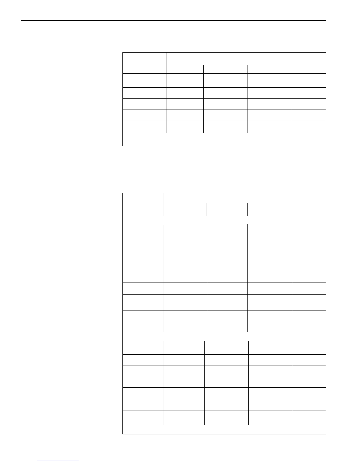
Terminal assignment Promag 50
Terminal No. (inputs / outputs)
Order variant 20 (+) / 21 (-) 22 (+) / 23 (-) 24 (+) / 25 (-) 26 (+) / 27 (-)
50***-***********W - - - Current output
HART
50***-***********A - - Frequency output Current output
HART
50***-***********D Status input Status output Frequency output Current output
HART
50***-***********S - - Frequency output Current output
IS, passive HART
50***-***********T - - Frequency output Current output
Intrinsically Safe HART
®
®
®
®
®
Ground connection, power supply → refer to illustration on top of page 6
Terminal assignment Promag 53
The inputs and outputs on the communication board can be either permanently
assigned or variable, depending on the version ordered (see table). Replacement
for modules which are defective or which have to be replaced can be ordered as
accessories.
Terminal No. (inputs / outputs)
Order variant 20 (+) / 21 (-) 22 (+) / 23 (-) 24 (+) / 25 (-) 26 (+) / 27 (-)
Fixed communication boards (fixed assignment)
53***-***********A - - Frequency output Current output
HART
53***-***********B Relay output 2 Relay output 1 Frequency output Current output
HART
53***-***********F - - - Profibus-PA
IS
53***-***********G - - - Foundation
Fieldbus IS
53***-***********H - - - Profibus-PA
53***-***********J - - - Profibus-DP
53***-***********K - - - Foundation
Fieldbus
53***-***********S - - Frequency output Current output
Intrinsically safe IS, active
HART
53***-***********T - - Frequency output Current output
Intrinsically safe IS, passive
HART
®
®
®
®
8
Flexible communication boards
53***-***********C Relay output 2 Relay output 1 Frequency output Current output
HART
53***-***********D Status input Relay output Frequency output Current output
HART
53***-***********L Status input Relay output 2 Relay output 1 Current output
HART
53***-***********M Status input Frequency output 2 Frequency output 1 Current output
HART
53***-***********2 Relay output Current output 2 Frequency output Current output
1 HART
53***-***********4 Current input Relay output Frequency output Current output
HART
53***-***********5 Status input Current input Frequency output Current output
HART
®
®
®
®
®
®
®
Ground connection, power supply → refer to illustration on top of page 6
Endress+Hauser
Page 9
Promag 50/53 W
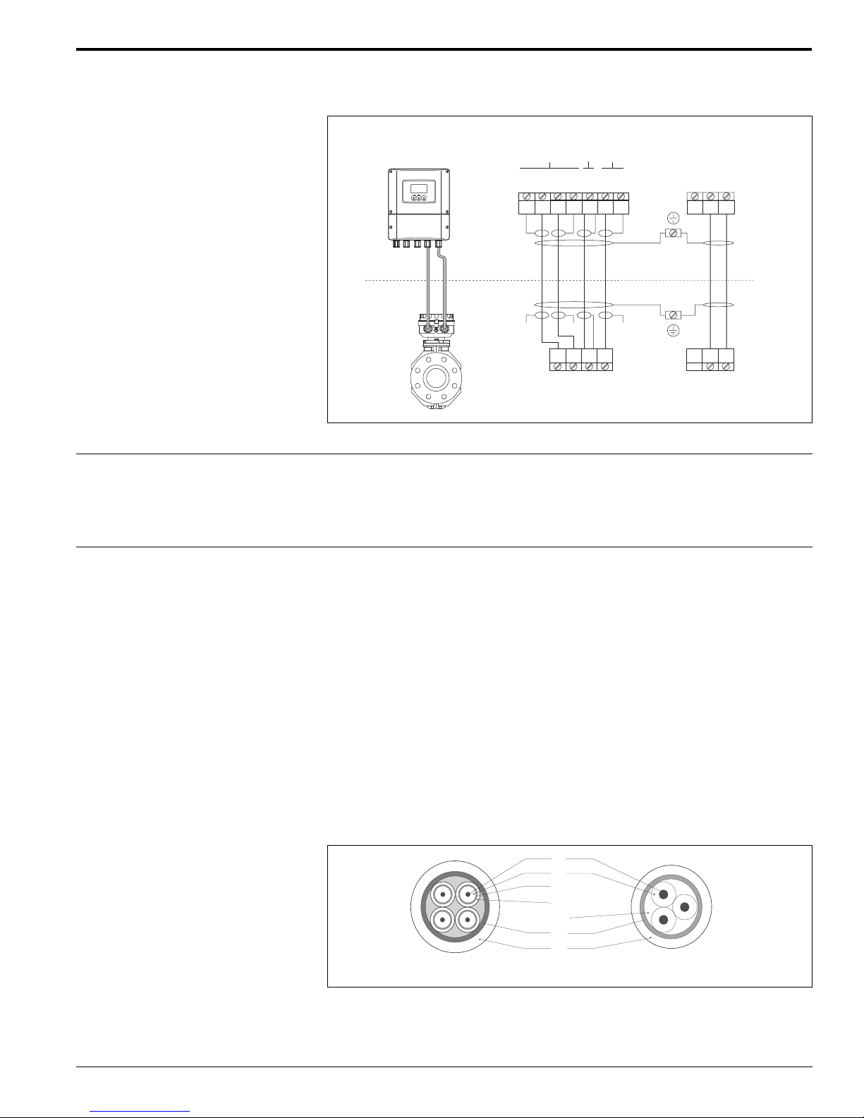
Electrical connection
remote version
Electrode Circuit
EPDMeas.signal Pipe
Cable entry
Cable specifications
remote version
Esc
-
+
E
n.c. = cable shields to be isolated and not to be connected
S1
6
n.c. n.c.n.c.
5
brown
E2
7
white
5
E1E1E2
S2
8
7
4
green
4
E
GND
373736
yellow
GND
S
E
Coil circuit
424241
2
1
41
Power-supply and signal cables (inputs/outputs):
• 1/2" NPT
Connecting cable for remote version:
• 1/2" NPT
Coil cable:
• 2 x 18 AWG (0.75 mm2) PVC cable with common, braided copper shield,
approximately 0.28” diameter (Ø approx. 7 mm)
• Conductor resistance: ≤ 0.011 Ω/ft (37 Ω/km)
• Capacitance: core/core, shield grounded: ≤ 36 pF/ft (120 pF/m)
• Permanent operating temperature: -5° to +180°F (–20 to +80°C)
• Cable cross-section: maximum 16 AWG (2.5 mm2)
Endress+Hauser
Signal cable:
• 3 x 20 AWG (0.38 mm
2
) PVC cable with common, braided copper shield,
approximately 0.28” diameter (Ø approx. 7 mm) and individually shielded cores.
• With Empty Pipe Detection (EPD): 4 x 20 AWG (0.38 mm2) PVC cable with
common, braided copper shield, approximately 0.28” diameter (Ø approx. 7 mm)
and individually shielded cores.
• Conductor resistance: ≤ 0.015 Ω/ft (50 Ω/km)
• Capacitance: core/shield: ≤ 128 pF/ft (420 pF/m)
• Permanent operating temperature: -5° to +180°F (–20 to +80 °C)
• Cable cross-section: maximum 16 AWG (2.5 mm2)
1
2
3
4
5
6
7
a
a = signal cable, b = coil current cable (maximum 16 AWG (2.5 mm2)
1 = Core 5 = Core strengthening
2 = Core insulation 6 = Cable shield
3 = Core shield 7 = Outer jacket
4 = Core jacket
b
9
Page 10
Promag 50/53 W
Endress+Hauser optionally supplies reinforced connecting cables with an additional
metal braid. We recommend such cables for the following cases:
• Underground laid cables
• Danger of rodent attack
• Device used with NEMA 6P (IP 68) ingress protection
Operation in areas of severe electrical interference:
The measuring device complies with the general safety requirements in accordance
with EN 61010, the EMC requirements of EN 61326, and NAMUR recommendation
NE 21.
Caution:
Grounding is by means of the ground terminals provided for that purpose inside the
connection housing. Keep the stripped and twisted lengths of cable shield to the
terminals as short as possible.
Supply voltage
Power consumption
Power supply failure
Potential equalization
85 to 260 VAC, 45 to 65 Hz
20 to 55 VAC, 45 to 65 Hz
16 to 62 V DC
PROFIBUS-PA and FOUNDATION Fieldbus
Nonhazardous: 9 to 32 VDC
Intrinsically safe: 9 to 24 VDC
Explosion proof: 9 to 32 VDC
AC: <15 VA (including sensor)
DC: <15 W (including sensor)
Switch-on current:
• maximum 13.5 A (< 50 ms) at 24 V DC
• maximum 3 A (< 5 ms) at 260 V AC
Lasting minimum 1 power cycle:
• EEPROM or T-DAT™ (Promag 53 only) retain the measuring-system data in the
event of a power supply failure
• S-DAT™ = exchangeable data storage chip which stores the data of the sensor:
nominal diameter, serial number, calibration factor, zero point, etc.
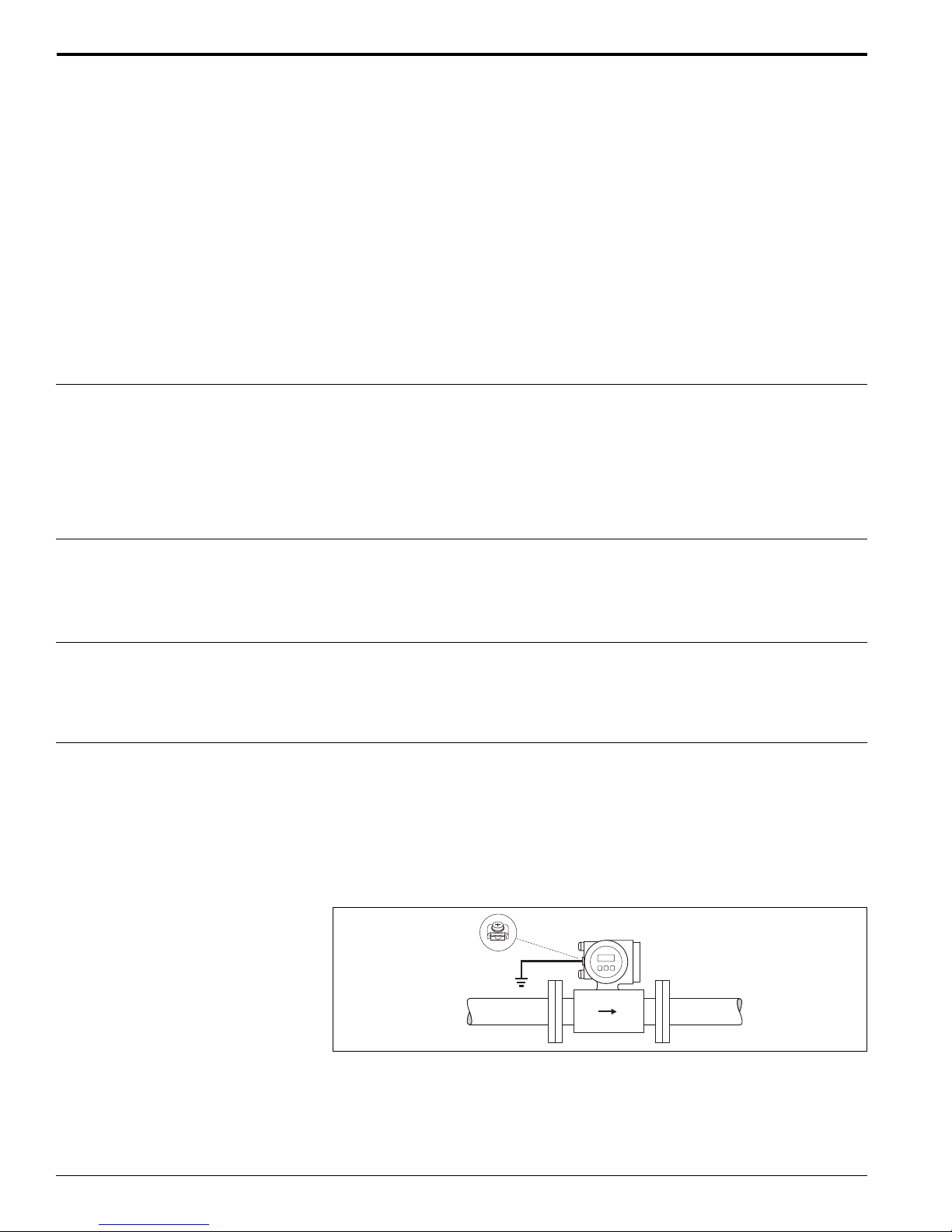
Standard case
Perfect measurement is only ensured when the medium and the sensor have the
same electrical potential. Most Promag sensors have a standard installed reference
electrode which guarantees the required potential matching. This usually means that
additional potential matching measures are unnecessary.
NOTE: For installation in metal pipes, it is advisable to connect the ground terminal
of the transmitter housing to the piping.
Caution:
For sensors without reference electrodes or without metal process terminals, carry
out potential matching as per the instructions for special cases described below.
These special measures are particularly important when standard grounding
practice cannot be ensured or extremely strong matching currents are expected.
Endress+Hauser10
Page 11
Promag 50/53 W
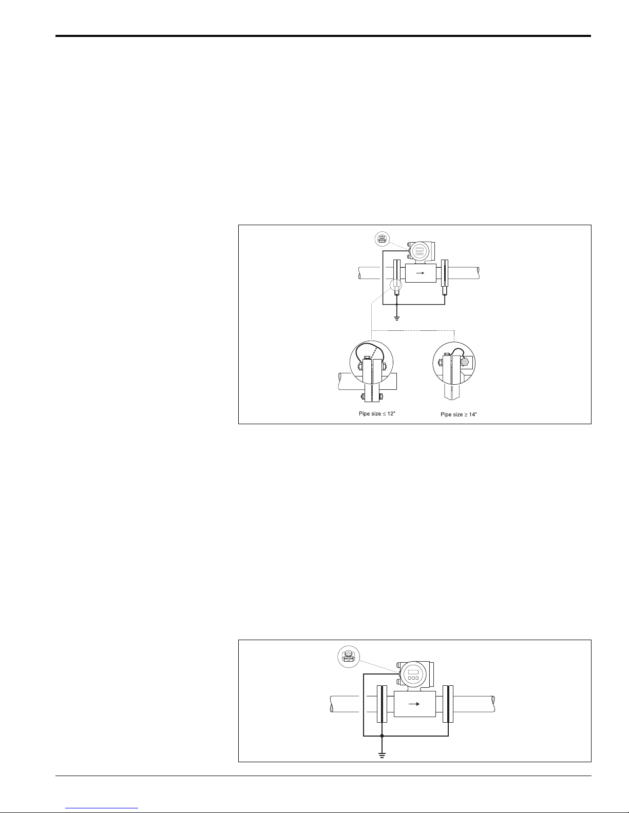
Metallic, ungrounded pipes
In order to avoid errors in measurement, use grounding cables to connect each
sensor flange to its corresponding pipe flange and ground the flanges. Connect the
transmitter or sensor connection housing, as applicable, to ground by means of the
grounding terminal provided for that purpose.
Note:
The grounding cable for flange-to-flange connections can be ordered separately as
an accessory from Endress+Hauser.
• ≤ 12”; the grounding cable is in direct connection with the conductive flange
coating and is secured by the flange screws.
• ≥ 14”, the grounding cable connects directly to the metal transport bracket.
9 AWG Cu
Plastic pipes and lined pipes
Normally, potential is matched using the reference electrodes in the measuring tube.
However, in exceptional cases it is possible that, due to the grounding plan of a
system, large matching currents flow over the reference electrodes. This can lead to
destruction of the sensor, e.g. through electrochemical decomposition of the electrodes. In such cases, e.g. for fiberglass or PVC piping, it is recommended that you
use additional ground disks for potential matching.
When using ground disks, not the following points:
• Ground disks (1” to 12”) can be ordered from Endress+Hauser as an accessory
• Ground disks (including seals) increase the installation length. Refer to the
disk dimensions on page 22.
Caution:
Risk of damage by electrochemical corrosion. Note the electrochemical insulation
rating if the grounding rings and measuring electrodes are made of different materials.
Observe the plant internal grounding guidelines.
Endress+Hauser 11
9 AWG Cu
Page 12
Promag 50/53 W
Pipes with cathodic protection
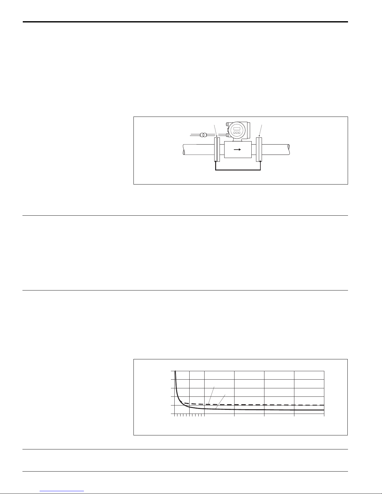
If the medium cannot be grounded for process-related reasons, the measuring
device must be installed in such a way as to be potential-free:
• When installing the measuring device, make sure that there is an electrical
connection between the two piping runs, 9 AWG copper wire (6 mm
2
).
• Make sure that the installation materials do not establish a conductive connection
to the measuring device and that the installation materials withstand the
tightening torques applied when the threaded fasteners are tightened.
• Also comply with the regulations applicable to potential-free installation.
bb
a
9 AWG Cu
a = isolating transformer, b = electrically insulated
Reference conditions
Measured error
Performance characteristics
To DIN 19200 and VDI/VDE 2641:
• Medium temperature: +28 °C ± 2 K
• Ambient temperature: +22 °C ± 2 K
• Warm-up time: 30 minutes
Installation:
• Inlet run >10 x Dia
• Outlet run > 5 x Dia
• Sensor and transmitter grounded.
• Sensor centered relative to the pipe.
Promag 50:
Pulse output: ± 0.5% o.r. ± 1 mm/s (o.r. = of reading)
Current output: plus typically ± 5 µA
Promag 53:
Pulse output: ± 0.2% o.r. ± 2 mm/s (o.r. = of reading)
Current output: plus typically ± 5 µA
Supply-voltage fluctuations have no effect within the specified range.
[%]
2.5
2.0
1.5
1.0
0.5
0
Measured error in [%] of reading
3
0
(1)
(2)
0.5 %
0.2 %
6
13
(4)
v ft/s (m/s)
(6)
20
26
(8)
33
(10)
Repeatability
12
± 0.1% o.r. ± 0.5 mm/s (o.r. = of reading)
Endress+Hauser
Page 13
Promag 50/53 W
h 2 x D³
Operating conditions
Installation conditions
Installation instructions Mounting location
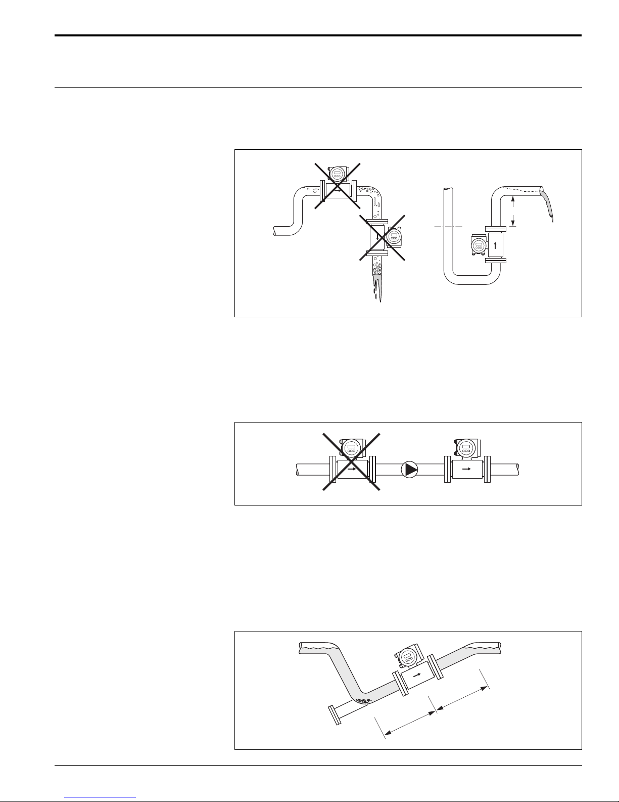
Correct measuring is possible only if the pipe is full. Avoid the following locations:
• Highest point in the run. Risk of air accumulating
• Directly upstream from an open pipe outlet in a down pipe
Installation of pumps
Do not install the sensor on the inlet side of a pump. This precaution is to avoid low
pressure and the consequent risk of damage to the lining of the measuring tube.
It might be necessary to install pulse dampers in systems incorporating reciprocating, diaphragm or peristaltic pumps. The sensor is shock and vibration resistant for
acceleration up to 2 g in accordance with IEC 68-2-6.
Partially filled pipes
Partially filled pipes with gradients necessitate a drain-type configuration. The Empty
Pipe Detection (EPD) function offers additional protection by detecting empty or
partially filled pipes.
Caution:
To avoid the risk of solids accumulating, do not install the sensor at the lowest point
in the drain. It is advisable to install a cleaning valve.
Endress+Hauser 13
³ 2 x D
³ 5 x D
Page 14
Promag 50/53 W
Vertical pipes
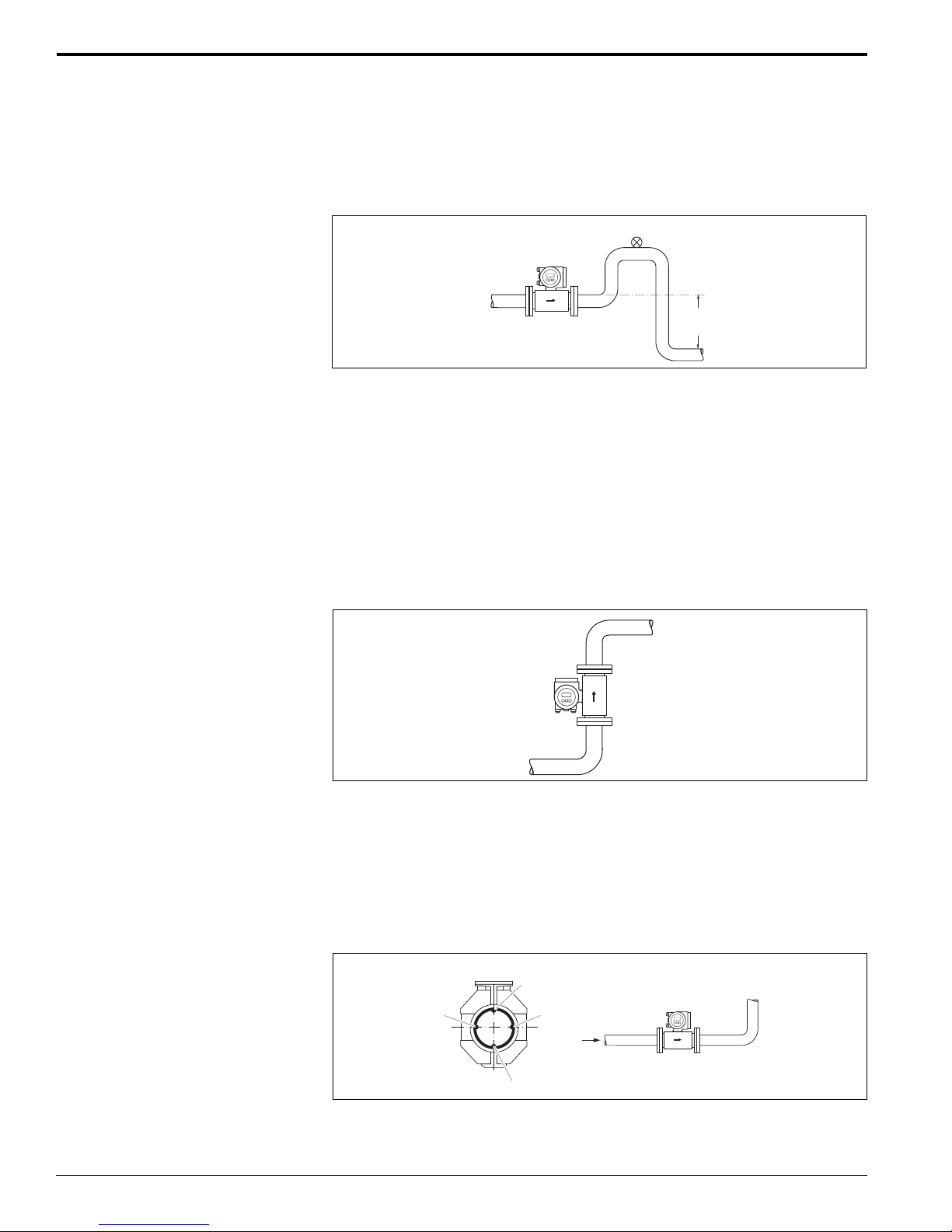
Install a siphon (b) or a vent valve (a) downstream of the sensor in vertical pipes
longer than 15 feet (5 meters). This precaution is to avoid low pressure and the
consequent risk of damage to the lining of the measuring tube. These measures also
prevent the system losing prime, which could cause air inclusions.
a
b
> 15 ft
(5 m)
a = vent valve, b = siphon
Orientation
An optimum orientation helps avoid gas and air accumulations and deposits in the
measuring tube. Promag, nevertheless, supplies a range of options and accessories
for correct measuring of problematic mediums:
• Electrode Cleaning Circuitry (ECC) to remove electrically conductive deposits in
the measuring tube, e.g. in accretive mediums
• Empty Pipe Detection (EPD) for recognition of partially filled measuring tubes, or
for degassing mediums or for applications with fluctuating process pressure.
Vertical orientation:
This orientation is ideal for self-emptying piping systems and for use in conjunction
with Empty Pipe Detection.
Horizontal orientation:
The measuring electrode-plane should be horizontal. This prevents brief insulation
of the two electrodes by entrained air bubbles.
Caution:
Empty Pipe Detection functions correctly only when the measuring device is installed
horizontally and the transmitter housing is facing upward. Otherwise, there is no
guarantee that Empty Pipe Detection will respond if the measuring tube is only
partially filled or empty.
A
1
2
1 = EPD electrode (Empty Pipe Detection)
2 = Measuring electrodes (signal detection)
3 = Reference electrode (potential equalization)
2
3
A
Endress+Hauser14
Page 15
Promag 50/53 W
> 30 feet
(> 10 m)
D
d
max. 4°
Vibrations
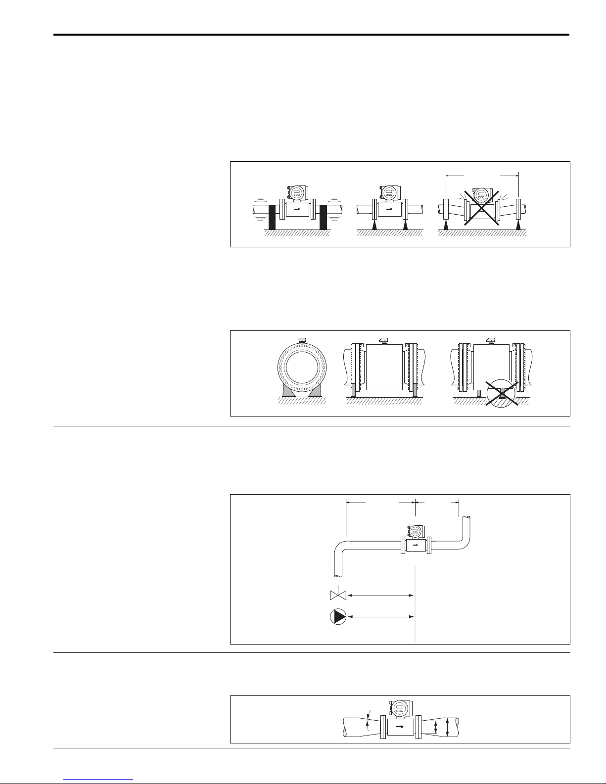
Secure the piping and the sensor if vibration is severe.
Caution:
It is advisable to install the sensor and transmitter separately if vibration is excessively severe. The sensor is shock and vibration resistant for acceleration up to 2 g
in accordance with IEC 68-2-6.
Foundations, supports
If the nominal diameter is 14” or larger, mount the sensor on a foundation of adequate loadbearing strength.
Caution:
Do not allow the sensor casing to take the weight of the sensor. This would buckle
the casing and damage the internal magnetic coils.
Inlet and outlet runs
If possible, install the sensor well clear of fittings such as valves, T-pieces, elbows,
etc. Compliance with the following requirements for the inlet and outlet runs is
necessary in order to ensure measuring accuracy:
• Inlet run ≥ 5 x pipe diameter
• Outlet run ≥ 2 x pipe diameter
5 x D³
2 x D³
Adapters With the help of the appropriate adapters (reducers and expanders) the sensor can
be mounted in a pipeline of a larger diameter. For slowly flowing fluids, the resulting
higher velocity increases the measuring accuracy.
Endress+Hauser 15
Page 16
Promag 50/53 W
Esc
E
-
+
200
100
5
33
(10)
330
(100)
650
(200)
L max
ft (m)
[ S/cm]m
L max
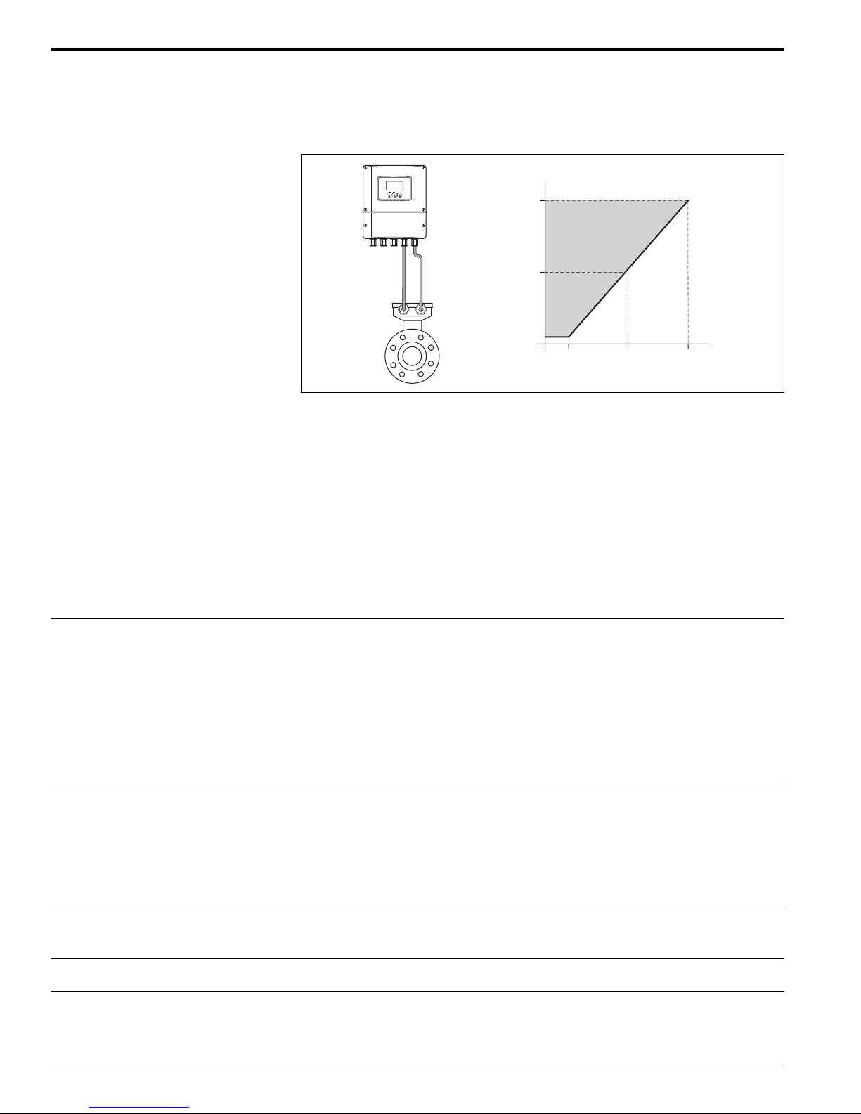
Length of connecting cable Permissible cable length Lmax depends on the conductivity of the medium. A
minimum conductivity of 20 µS/cm is required for measuring demineralized water.
Gray shaded area = permissible range for medium conductivity
Lmax = length of connecting cable in feet (m)
Medium conductivity in µS/cm
In order to ensure measuring accuracy, comply with the following instructions when
installing the remote version:
• Secure the cable run or route the cable in a conduit. Movement of the cable
can falsify the measuring signal, particularly if the conductivity of the medium
is low.
• Route the cable well clear of electrical machines and switching elements.
• Ensure ground equalization between the sensor and transmitter, if necessary.
Environment
Ambient temperature Standard: -5° to +140°F (-20° to +60°C) for sensor and transmitter
Optional: -40° to +140°F (-40° to +60°C)
Note the following points:
• Install the device at a shady location. Avoid direct sunlight, particularly in
warm climatic regions.
• If both medium and ambient temperatures are high, specify the remote
transmitter (refer to the “Medium temperature” ranges).
• At ambient temperatures below -5°F (-20°C), the readability of the display may
be impaired.
Storage temperature
Degree of protection
15° to + 120°F (-10° to +50°C), 70°F (20°C) is the preferable storage temperature.
• The measuring device must be protected against direct sunlight during storage
in order to avoid unacceptably high surface temperatures.
• Choose a storage location where moisture does not collect in the measuring
device. This helps prevent mold, fungus and bacteria from damaging the liner.
• Do not remove the protective plates or caps on the process connections until the
device is ready to install.
• Standard: NEMA 4X (IP 67) for transmitter and sensor
• Optional: NEMA 6P (IP 68) for Promag W sensor, remote version
Shock and vibration resistance
Electromagnetic compatibility (EMC)
Acceleration up to 2 g in accordance with IEC 68-2-6
To EN 61326 and NAMUR recommendation NE 21
Endress+Hauser16
Page 17
Promag 50/53 W
Process conditions
Medium temperature range The permissible medium temperature depends on the measuring tube liner:
• Polyurethane, -5° to +125°F (-20° to +50°C) for 1” to 78” sensors
• Hard rubber, 32° to +180°F (0° to +80°C) for 3” to 78” sensors
Conductivity Minimum conductivity:
≥ 5µS/cm → for fluids generally
≥ 20µS/cm → for demineralized water
Note that in the case of the remote version, the minimum conductivity is also influenced by the length of the connecting cable. Refer to “Length of connecting cable”.
Medium pressure range
(nominal pressure)
Pressure tightness (liner)
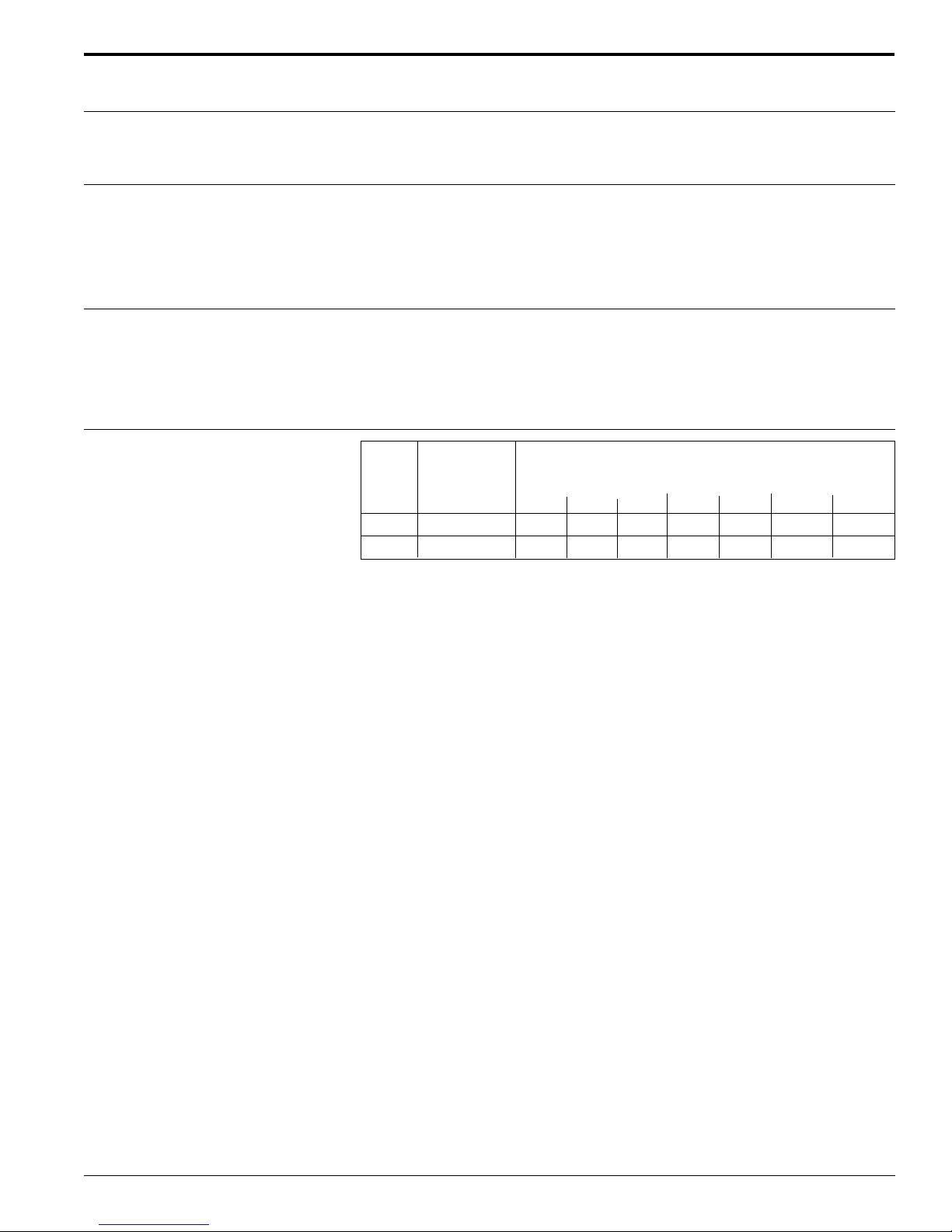
ANSI B 16.5:
Class 150, 1” to 24”
Class 300, 1” to 6”
AWWA:
Class D, 28” to 78”
Size Measuring Resistance to partial vacuum of measuring tube lining
tube limit values for abs. pressure (psia) at various
lining fluid temperatures
75°F 160°F 175°F 212°F 265°F 300°F 355°F
1” to 40” Polyurethane 0 0 - - - - 3” to 78” Hard rubber 0 0 0 - - - -
Endress+Hauser 17
Page 18
Promag 50/53 W
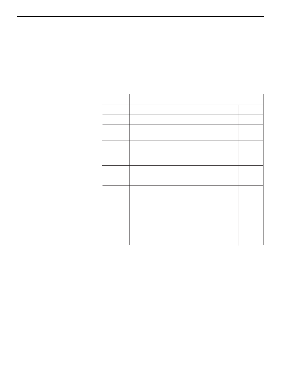
Flow limit
As a rule, the pipeline diameter determines the sensor diameter. With a known
flowrate and the help of the Endress+Hauser Flow Applicator, the best size can be
selected. Generally, a velocity range of 6 to 10 ft/sec should be selected.
A necessary increase in velocity can be achieved through a reduction of the sensor
diameter. The higher installation expense is normally balanced by the lower sensor
cost.
The flow velocity should also be determined by the fluid’s physical properties:
• v < 6 ft/sec, for abrasive mediums such as potter’s clay, lime milk, ore slurry, etc.
• v > 6 ft/sec, for fluids causing build-up such as wastewater sludge, etc.
Nominal
diameter
inch
1
1-1/2
2
3
4
6
8
10
12
14
16
18
20
24
28
30
32
36
40
42
48
54
60
66
72
78
mm
25
40
50
80
100
150
200
250
300
350
400
450
500
600
700
750
800
900
1000
1050
1200
1350
1500
1650
1800
2000
Recommended
flow rate
Min./max. full scale value
(v ~ 1.0 or 33 ft/s)
2.5 to 80 gpm
7 to 190 gpm
10 to 300 gpm
24 to 800 gpm
40 to 1250 gpm
90 to 2650 gpm
155 to 4850 gpm
250 to 7500 gpm
350 to 10,600 gpm
500 to 15,000 gpm
600 to 19,000 gpm
800 to 24,000 gpm
1000 to 30,000 gpm
1400 to 44,000 gpm
1900 to 60,000 gpm
2150 to 67,000 gpm
2450 to 80,000 gpm
3100 to 100,000 gpm
3800 to 125,000 gpm
4200 to 135,000 gpm
5500 to 175,000 gpm
9 to 300 Mgal/day
12 to 380 Mgal/day
14 to 500 Mgal/day
16 to 570 Mgal/day
18 to 650 Mgal/day
Full scale value
(v ~ 8 ft/s)
200 gpm
300 gpm
600 gpm
1200 gpm
1500 gpm
2400 gpm
3600 gpm
4800 gpm
6000 gpm
7500 gpm
10,500 gpm
13,500 gpm
16,500 gpm
19,500 gpm
24,000 gpm
30,000 gpm
33,000 gpm
52,000 gpm
75 Mgal/day
95 Mgal/day
120 Mgal/day
140 Mgal/day
175 Mgal/day
18 gpm
50 gpm
75 gpm
Factory settings
Pulse weighting
(~ 2 pulses/s)
0.20 gal
0.50 gal
0.5 gal
2 gal
2 gal
5 gal
10 gal
15 gal
25 gal
30 gal
50 gal
50 gal
75 gal
100 gal
125 gal
150 gal
200 gal
225 gal
250 gal
250 gal
400 gal
0.0005 Mgal/day
0.0005 Mgal/day
0.00075 Mgal/day
0.00075 Mgal/day
0.001 Mgal/day
Creepage
(~ 0.1 ft/s)
0.25 gpm
0.75 gpm
1.25 gpm
2.5 gpm
4.0 gpm
12 gpm
15 gpm
30 gpm
45 gpm
60 gpm
60 gpm
90 gpm
120 gpm
180 gpm
210 gpm
270 gpm
300 gpm
360 gpm
480 gpm
600 gpm
600 gpm
1.3 Mgal/day
1.3 Mgal/day
2.2 Mgal/day
2.6 Mgal/day
3.0 Mgal/day
Pressure loss No pressure loss if the sensor is installed in a pipe of the same nominal diameter.
Pressure losses occur in configurations incorporating adapters (reducers, expanders). Contact your Endress+Hauser representative or Endress+Hauser for information.
Endress+Hauser18
Page 19
Promag 50/53 W
13.9"
(355)
6.57"
(167)
10.4"
(265)
9.53"
(242)
Blind version
7.40"
(188)
5.24"
(133)
4.84"
(123)
Æ 0.34"
(8.6 M8)
3.94"
(100)
3.94"
(100)
Mechanical construction
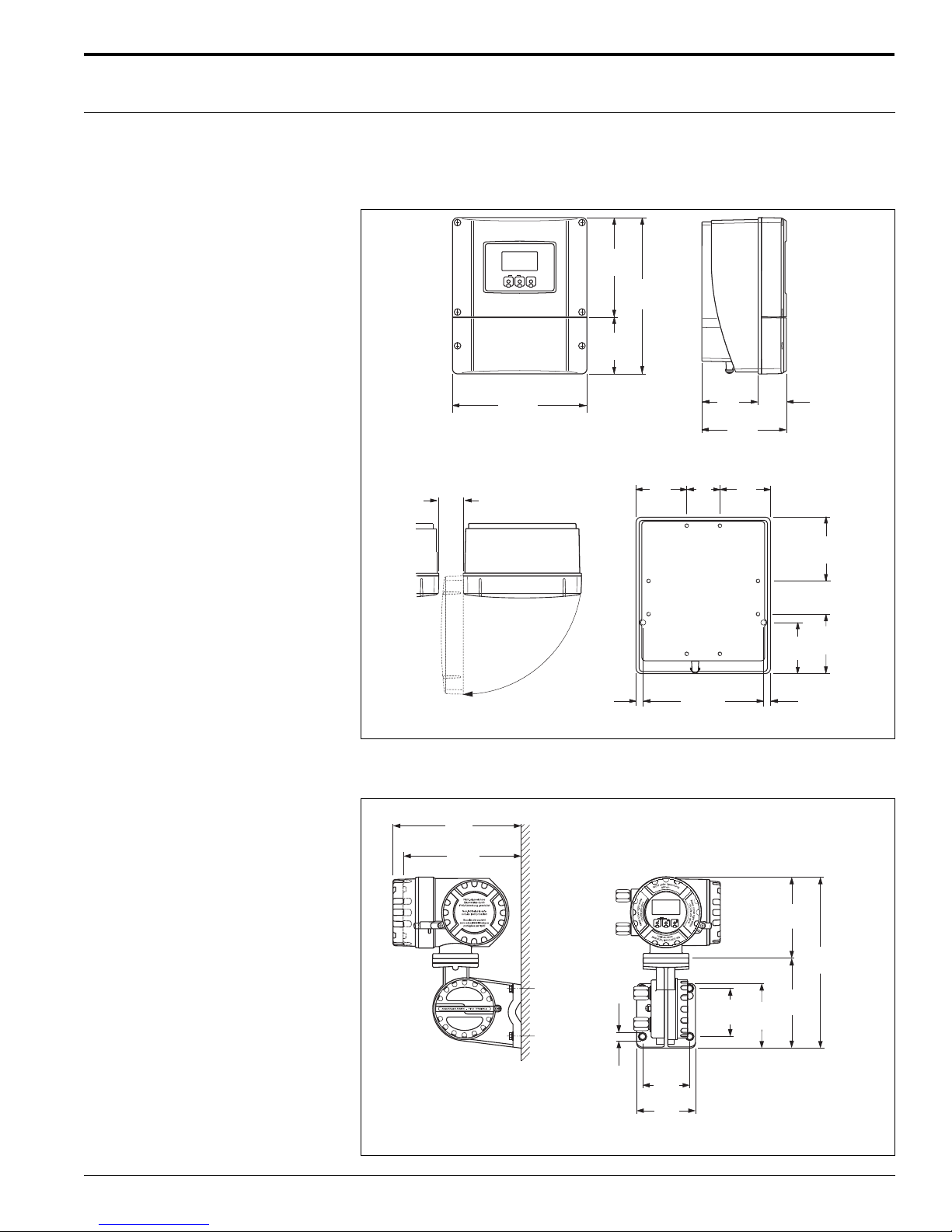
Dimensions / mounting details Wall mounted housing
Weight: 13 lbs (6 kg)
NOTE: A mounting kit (for panel or post mounting) is available from
Endress+Hauser. Please refer to Accessories.
> 1.97"
(50)
Esc
-
+
8.46"
(215)
6.27"
E
(159.5)
9.84"
(250)
3.56"
(90.5)
3.54"
1.77"
(90)
(45)
5.31"
(135)
2.08"
(53)
3.18"
(81)
3.18"
(81)
Remote field housing
(nonhazardous areas only U.S.)
Dimensions in inches (mm)
0.45"
(11.5)
7.55"
(192)
3.20"
(81.5)
4.01"
(102)
2.08"
(53)
3.74"
(95)
0.45"
(11.5)
Endress+Hauser 19
Page 20
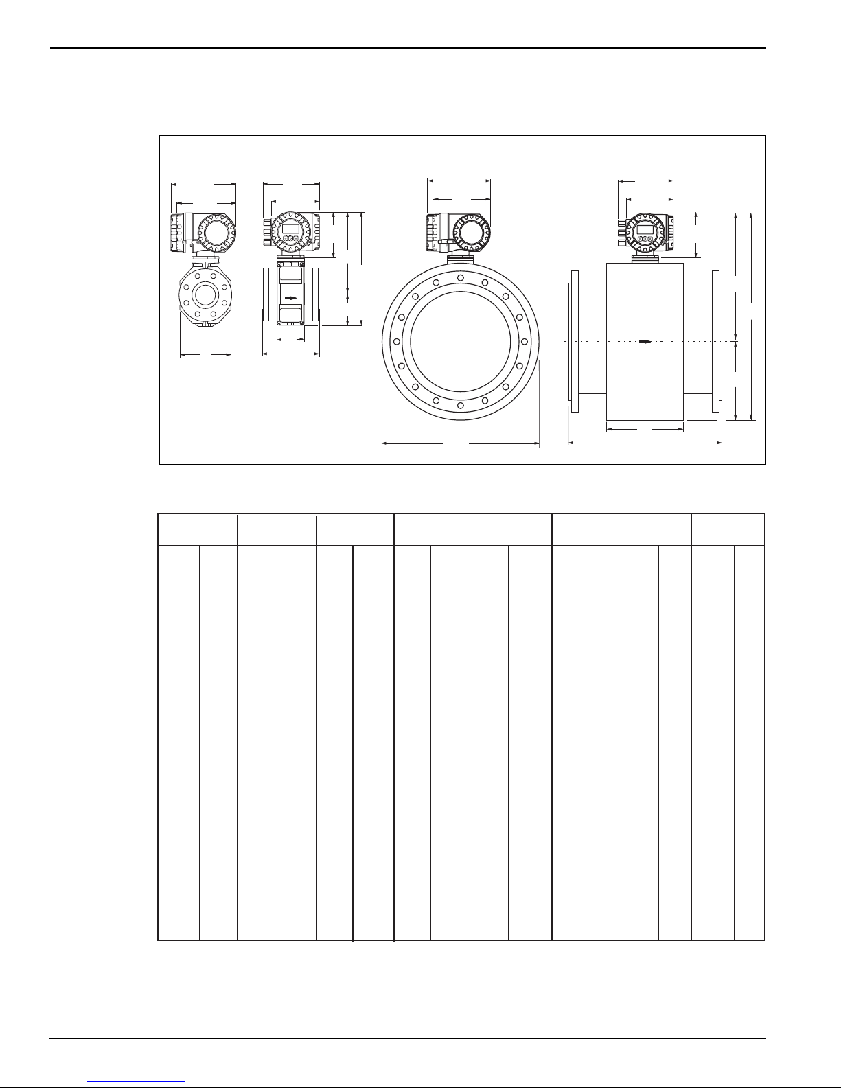
Promag W (compact version)
Promag 50/53 W
Promag W 1" to 12”
Compact Version
8.94"
(227)
8.15" *
(207)
K
Dimensions in inches (mm)
Nominal
Size
inches mm
1
1-1/2
2
3
4
6
8
10
12
14
16
18
20
24
28
30
32
36
40
1000
42
1050
48
1200
54
1350
60
1500
66
1650
72
1800
78
2000
25
40
50
80
100
150
200
250
300
350
400
450
500
600
700
750
800
900
in mm
7.87
7.87
7.87
7.87
9.84
11.8
13.8
17.7
19.7
21.6
23.6
25.6
25.6
30.7
35.8
38.4
40.9
46.0
51.2
53.7
61.4
69.1
76.8
84.4
92.1
102.3
7.68"
(195)
6.61"
(168)
6.30"
Esc
-
+
E
(160)
E
L
* Blind option dimension
L
13.4
200
13.4
200
13.4
200
15.4
200
15.4
250
18.6
300
20.7
350
22.7
450
24.7
500
29.1
550
31.1
600
33.1
650
35.1
650
39.2
780
47.2
910
47.2
975
48.9
1040
54.9
1170
60.9
1300
62.9
1365
71.7
1560
78.7
1755
86.5
1950
92.9
2145
100.4
2340
104.3
2600
B
A
C
A
in mm
341
341
341
391
391
472
527
577
627
738.5
790.5
840.5
891.5
995.5
1198.5
1198.5
1241.5
1394.5
1546.5
1598.5
1796.5
1998.5
2196.5
2360.5
2550.5
2650.5
in mm
10.1
10.1
10.1
11.1
11.1
12.7
13.6
14.6
15.6
17.9
18.9
19.9
20.9
23.0
27.0
27.0
27.9
30.9
33.9
34.9
38.8
42.8
46.7
49.9
53.6
55.6
B
257
257
257
282
282
322
347
372
397
456.5
482.5
507.5
533
585
686.5
686.5
708
784.5
860.5
886.5
985.5
1086.5
1185.5
1267.5
1362.5
1412.5
8.94"
(227)
8.15" *
(207)
K
in mm
3.31
3.31
3.31
4.29
4.29
5.90
7.08
8.07
9.05
11.1
12.1
13.1
14.1
16.2
20.1
20.1
21.0
24.0
27.0
28.0
31.9
35.9
39.8
43.0
46.8
48.7
C
358.5
410.5
533.5
1011
1093
1188
1238
NOTE: The fitting length (L) is always the same, regardless of the pressure rating.
* Weight data valid for 150 lb ANSI and AWWA Class D versions.
Promag W 14" to 78”
Compact Version
K
in mmEin mm
84
4.72
84
4.72
84
4.72
109
7.08
109
7.08
150
10.2
180
12.7
205
15.7
230
18.1
282
22.2
308
24.2
333
26.2
28.2
32.3
512
40.3
512
40.3
42.0
610
48.0
686
54.0
712
56.0
811
63.8
912
71.8
79.6
86.0
93.5
97.5
120
120
120
180
180
260
324
400
460
564
616
666
717
821
1024
1024
1067
1220
1372
1424
1622
1824
2022
2186
2376
2476
7.68"
(195)
(168)
Esc
-
3.70
3.70
3.70
3.70
3.70
5.51
6.14
6.14
6.53
10.9
10.9
11.5
11.5
15.8
23.2
24.6
25.5
30.9
33.9
35.9
39.0
42.3
54.8
58.3
64.2
68.2
6.61"
+
E
L
6.30"
E
(160)
B
A
C
Weight *
lb kg
16
20
23
31
35
56
99
165
242
386
452
562
628
893
882
1014
1212
1764
1984
2425
3086
4850
5952
8157
9039
7.3
9.4
10.6
14
16
25.5
45
75
110
175
205
255
285
405
400
460
550
800
900
1100
1400
2200
2700
3700
4100
4600
94
94
94
94
94
140
156
156
166
276
276
292
292
402
589
626
647
785
862
912
992
1252
1392
1482
1632
1732
10,1421
Endress+Hauser20
Page 21
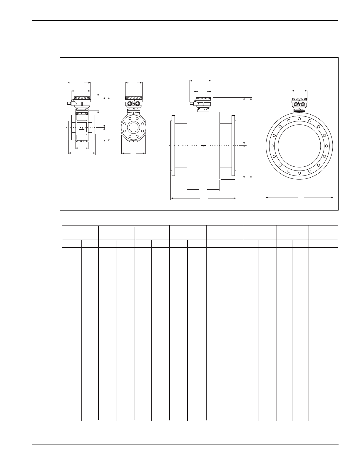
Promag 50/53 W
Promag W (remote version)
Promag W 1” to 12"
Remote Version
B
in mm
202
202
202
227
227
267
292
317
342
401.5
427.5
452.5
478
530
631.5
631.5
653
729.5
805.5
831.5
930.5
1031.5
1130.5
1212.5
1307.5
1357.5
6.73"
(171)
5.63"
(143)
E
L
in mm
3.31
3.31
3.31
4.29
4.29
5.90
7.08
8.07
9.05
11.1
12.1
13.1
14.1
16.2
20.1
20.1
21.0
24.0
27.0
28.0
31.9
35.9
39.8
43.0
46.8
48.7
6.73"
(171)
5.63"
(143)
4.01"
(102)
B
C
E
L
Dimensions in inches (mm)
Nominal
Size
inches mm
7.87
1
1-1/2
2
3
4
6
8
10
12
14
16
18
20
24
28
30
32
36
40
42
48
54
60
66
72
78
25
40
50
80
100
150
200
250
300
350
400
450
500
600
700
750
800
900
1000
1050
1200
1350
1500
1650
1800
2000
7.87
7.87
7.87
9.84
11.8
13.8
17.7
19.7
21.6
23.6
25.6
25.6
30.7
35.8
38.4
40.9
46.0
51.2
53.7
61.4
69.1
76.8
84.4
92.1
102.3
A
L
in mm
1040
1170
1300
1365
1560
1755
1950
2145
2340
2600
200
200
200
200
250
300
350
450
500
550
600
650
650
780
910
975
5.08"
(129)
K
in mm
11.2
11.2
11.2
13.2
13.2
16.4
18.6
20.5
22.5
26.9
29.0
30.9
32.9
37.0
45.0
45.0
46.7
52.7
58.7
60.7
68.5
76.5
84.3
90.8
98.2
102.2
A
286
286
286
336
336
417
472
522
572
683.5
735.5
785.5
836.5
940.5
1143.5
1143.5
1186.5
1339.5
1491.5
1543.5
1741.5
1943.5
2141.5
2305.5
2495.5
2595.5
7.95
7.95
7.95
8.94
8.94
10.5
11.5
12.5
13.5
15.8
16.8
17.8
18.8
20.9
24.9
24.9
25.7
28.7
31.7
32.7
36.6
40.6
44.5
47.7
51.5
53.4
NOTE:The fitting length (L) is always the same, regardless of the pressure rating
* Weight data valid for 150 lb ANSI and AWWA Class D versions
Promag W 14" to 78”
Remote Version
B
A
C
C
in mmEin mm
84
4.72
84
4.72
84
4.72
109
109
150
180
205
230
282
308
333
358.5
410.5
512
512
533.5
610
686
712
811
912
1011
1093
1188
1238
7.08
7.08
10.2
12.7
15.7
18.1
22.2
24.2
26.2
28.2
32.3
40.3
40.3
42.0
48.0
54.0
56.0
63.8
71.8
79.6
86.0
93.5
97.5
K
120
120
120
180
180
260
324
400
460
564
616
666
717
821
1024
1024
1067
1220
1372
1424
1622
1824
2022
2186
2376
2476
3.70
3.70
3.70
3.70
3.70
5.51
6.14
6.14
6.53
10.9
10.9
11.5
11.5
15.8
23.2
24.6
25.5
30.9
33.9
35.9
39.0
42.3
54.8
58.3
64.2
68.2
5.08"
(129)
K
94
94
94
94
94
140
156
156
166
276
276
292
292
402
589
626
647
785
862
912
992
1252
1392
1482
1632
1732
Weight *
lb kg
12
16
19
24
31
52
95
161
238
381
448
558
624
888
877
1010
1208
1759
1980
2421
3082
4846
5948
8153
9035
10,137
5.3
7.4
8.6
12
14
23.5
43
73
108
173
203
253
283
403
398
458
548
798
898
1098
1398
2198
2698
3698
4098
4598
Endress+Hauser 21
Page 22
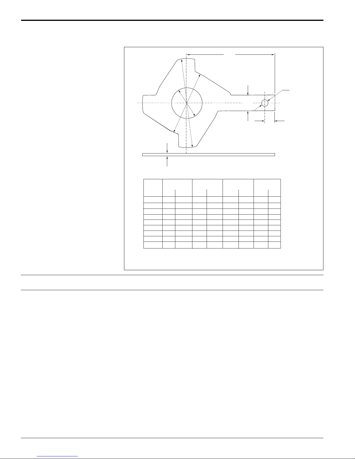
Promag 50/53 W
Ground disk, 1” to 12”
H
Ø B
Ø A
Ø D
0.08"
(2)
in mm
1.18
1.75
2.22
3.35
4.33
6.42
8.29
10.4
12.5
A
30
44.5
56.5
85
110
163
210.5
265
317
Nominal
1)
size
1
1-1/2
2
3
4
6
8
10
2)
12
1)
Ground disks, apart from those for 12", can be used for all
supplied flange standards / pressure ratings
2)
Class 150
B
in mm
2.44
3.23
3.98
5.16
6.14
8.54
10.5
12.9
14.8
62
82
101
131
156
217
267
328
375
D
in mm
3.05
3.98
4.55
6.08
7.34
10.1
11.3
14.1
16.3
0.59"
(15)
77.5
101
115.5
154.5
186.5
256
288
359
413
H
in mm
3.44
4.06
4.25
5.31
6.02
7.24
8.07
9.45
10.7
Æ 0.26"
(6.5)
0.39"
(10)
87.5
103
108
135
153
184
205
240
273
Weight Refer to Pages 20 to 21.
Materials
Transmitter housing:
• Compact housing: powder coated die-cast aluminum
• Remote field housing: powder coated die-cast aluminum
• Wall mounted housing: powder coated die-cast aluminum
Sensor housing:
• 1” to 12”: powder coated die-cast aluminum
• 14” to 78”: painted steel (Amerlock 400)
Measuring tube:
• < 14”: 304 SS or 304L SS with Al/Zn protective coating when supplied with
non-stainless flange material
• > 12”: 304 SS with Amerlock 400 paint when supplied with non-stainless flange
material
Flanges:
• ANSI: A105 CS (< 14” with Al/Zn protective coating; > 12” with
Amerlock 400 paint) or 316L SS
• AWW A: A36
Electrodes:
• Standard, 316L SS; optional Alloy C-22, tantalum
Seal:
• Seals to DIN 2690
Ground disks (accessory):
• 316L SS or Alloy C-22
Endress+Hauser22
Page 23
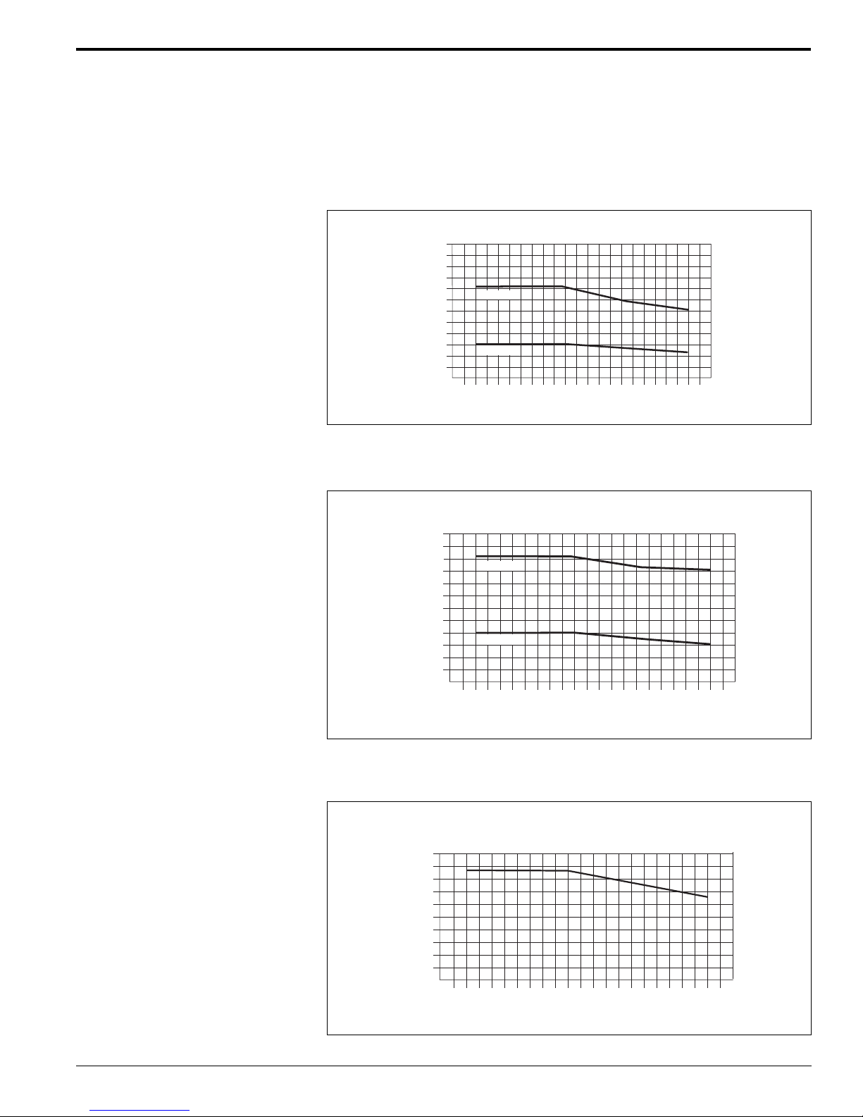
Promag 50/53 W
Material load diagrams Caution!
The following material load diagrams are refering to a temperature range of -40° to
+356°F (-40° to +180°C) reference curves. The maximum permissible fluid temperature always depends on the lining material of the sensor and/or the seal material.
Flange, 316L SS, ANSI B16.5
[psi]
870
725
580
435
290
145
0
-76
-60
Class300
Class150
-40
-40-4-20
Flange, A105 CS, ANSI B16.5
[psi]
870
725
580
435
290
145
0
-76
-60
Class300
Class150
-40
-40-4-20
[bar]
60
50
40
30
20
10
0
10440140
32
68
0
20
60
176
80
212
100
248
120
284
140
320
160
[°F]
[°C]
[bar]
60
50
40
30
20
10
0
68
20
10440140
60
32
0
176
80
212
100
248
120
284
140
320
160
[°F]
[°C]
Endress+Hauser 23
Flange, A105 CS, to AS2129 Table E
[psi]
160
145
130
115
100
0
-76
-60
-40
-40-4-20
32
0
68
20
10440140
60
176
80
212
100
248
120
284
140
320
160
[bar]
11
10
9
8
7
0
[°F]
[°C]
Page 24

Fitted electrodes Measuring, reference and Empty Pipe Detection electrodes:
• Standard with: 316L SS, Alloy C-22 or tantalum
• Optional: exchangeable measuring electrodes, 316L SS, 14” to 78”. For hard
rubber liner only, no EPD or reference electrodes, for safe areas only.
Promag 50/53 W
Process connections
Surface roughness
Display elements
Operating elements
Flange connections: ANSI
• Electrodes:
- 316L SS, Alloy C-22, tantalum: 12
All data relates to wetted parts.
µ
in to 20 µin (0.3 µm to 0.5 µm)
Human interface
• Liquid crystal display, backlit, two lines (Promag 50) or four lines (Promag 53)
with 16 characters per line
• Custom configurations for presenting different measured value and status
variables
• Flow rate: 5 digits with sign and units
• Totalizer :
Promag 50: 2 totalizers (7-digit plus 7-digit overflow with sign and units)
Promag 53: 3 totalizers (7-digit plus 7-digit overflow with sign and units)
Unified operation concept for both types of transmitter:
Promag 50:
• Local operation with three push buttons (-, +, E)
• Quick Setup menus for straightforward commissioning
Promag 53:
• Local operation with Touch Control (-, +, E)
• Application specific Quick Setup menus for straightforward commissioning
Remote operation
Promag 50; remote operation via HART®, PROFIBUS-PA
Promag 53; remote operation via HART®, PROFIBUS-PA/DP, FOUNDATION fieldbus
Endress+Hauser24
Page 25

Promag 50/53 W
Certificates and approvals
Hazardous area approvals Information on the currently available hazardous area rated versions
(FM, CSA, ATEX, etc.) is available on request from Endress+Hauser. All information
relevant to explosion protection is available in separate documentation.
CE mark
Pressure equipment directive
PROFIBUS-DP/PA certification
FOUNDATION Fieldbus certification
By attaching the CE mark, Endress+Hauser confirms that the instrument fulfills all the
requirements of the relevant EC directives.
Flow meters with a nominal diameter smaller or equal to 1” (DN 25) are covered by
Art. 3(3) of the European directive 97/23/EG (Pressure Equipment Directive) and are
designed according to sound engineering practice. For larger nominal diameters,
optional approvals according to Cat. III are available when required (depends on the
fluid and process pressure).
The flow device has successfully passed all the test procedures carried out and is
certified and registered by the PNO (PROFIBUS User Organization). The device thus
meets all the requirements of the following specifications:
• Certified to PROFIBUS-PA, profile version 3.0 (device certification number on
request)
• The device can also be operated with certified devices of other manufacturers
(interoperability)
The flow device has successfully passed all the test procedures carried out and is
certified and registered by the Fieldbus FOUNDATION. The device thus meets all the
requirements of the following specifications:
• Certified to FOUNDATION Fieldbus Specification
• The device meets all the specifications of the FOUNDATION Fieldbus H1
• Interoperability Test Kit (ITK), revision status 4.0 (device certification number on
request)
• The device can also be operated with certified devices of other manufacturers
• Physical Layer Conformance Test of the Fieldbus FOUNDATION
Other standards, guidelines
EN 60529:
Degrees of protection by housing (IP Code)
EN 61010:
Protection Measures for Electrical Equipment for Measurement, Control, Regulation
and Laboratory Procedures
EN 61326/A1 (IEC 1326):
Electromagnetic compatibility (EMC requirements)
NAMUR 21:
Electromagnetic compatibility (EMC) of industrial process and laboratory control
equipment
NAMUR 43:
Standarization of the signal level for the breakdown information of digital transmitters
with analog output signals
Endress+Hauser 25
Page 26

Ordering information
Promag 50 W Electromagnetic Flowmeter, 1” to 24” sizes
1 2 3 4 5 6 7 8 9 10 11 12 13
Promag 50 W -
Promag 50/53 W
Nominal Diameter
1251”
40 1-1/2”
50 2”
80 3”
1H 4”
1F 6”
2H 8”
2F 10”
3H 12”
3F 14”
4H 16”
4F 18”
5H 20”
6H 24”
2 Liner
H Hard rubber
U Polyurethane
3 Process Connection
L Class 150 ANSI B16.5 carbon steel A105 flanges
M Class 300 ANSI B16.5 carbon steel A105 flanges
R Class 150 ANSI B16.5, 316L SS flanges
S Class 300 ANSI B16.5, 316L SS flanges (not for 8” and
larger sensors)
9 Other
4 Electrodes / Material
0 Measuring, reference and EPD electrodes / 316L SS
1 Measuring, reference and EPD electrodes / Alloy C-22
2 Measuring, reference and EPD electrodes / tantalum
7 Measuring electrode, exchangeable / 316L SS
(for hard rubber liner only, 14” and larger sensors, no EPD or
reference electrodes, for safe areas only)
G Measuring, reference and EPD electrodes, bullet nose / 316L SS
H Measuring, reference and EPD electrodes, bullet nose / Alloy C-22
9 Other
5 Calibration
A 3-point calibration, 0.5%
B 3-point calibration, 0.2%
D SCS/A2LA 3-point 0.5% calibration (ISO/IEC 17025) with certificate
traceable according to ISO 9000 (specify flow range)
E SCS/A2LA 3-point 0.2% calibration (ISO/IEC 17025) with certificate
traceable according to ISO 9000 (specify flow range)
9 Other
6 Certificates
1 Standard, no certificate
2 3.1B material certificate for pipe and flanges
3 2.3 pressure test certificate (1.5 x PN, 3 minutes) for sensors
up to 12” only
4 3.1B material and 2.3 pressure test certificate for sensors
up to 12” only
5 CRN approval for ANSI flanges only
8 CRN approval, 3.1B material certificate and 2.3 pressure test
certificate (1.5 x PN) for ANSI flanges only
7 Approvals
A For use in nonhazardous areas
N FM explosion proof Class I, Div. 1 / CSA Class I, Div. 1 (only for
aluminum field housing, compact version, not for 14” and larger
sensors)
R FM non-incendive Class I, Div. 2 / CSA Class I, Div. 2
8 Protection type / Version
A NEMA 4X / compact, aluminum field housing
C NEMA 4X / remote wall mounted housing (only for approvals A or R)
G NEMA 4X / remote aluminum field housing for nonhazardous areas
K NEMA 6P / remote, wall mounted housing (only for approvals A or R)
N NEMA 6P / remote aluminum field housing, nonhazardous
1 -40°F (-40°C) ambient temperature, NEMA 4X / compact aluminum
housing for transmitter (only for approvals A or R)
3 -40°F (-40°C) ambient temperature, NEMA 4X / compact SS housing
for transmitter (only for approvals A or R)
5 -40°F (-40°C) ambient temperature, NEMA 4X / remote wall mount
housing for transmitter (only for approvals A or R)
9 Other
9 Cable for Remote Version
0 Without cable
1 15 foot coil and signal cable
2 30 foot coil and signal cable
5 Coil and signal cable, specify length in feet, maximum 650 feet,
depending on conductivity of process material
9 Other
10 Cable Entries
B 1/2” NPT
L Fieldbus connector (Outputs / Inputs H and Approval A only)
X Sensor only, without cable (compact version only)
9 Other
11 Display / Power Supply / Operation
7 85 to 260 VAC, without display, remote configuration only (not for
wall mount or SS housing)
8 20 to 55 VAC / 16 to 62 VDC, without display, remote configuration
only (not for wall mount or SS housing)
A 85 to 260 VAC, with display, push button operation (language: EN,
ES, FR, IT, NL, PT, DE)
B 20 to 55 VAC / 16 to 62 VDC, with display, push button operation
(language: EN, ES, FR, IT, NL, PT, DE)
X Sensor only (without transmitter, only available up to 8”)
12 Software
A Standard
X Sensor only
13 Outputs / Inputs
W Current / HART
A Current / HART, frequency
D Current / HART, frequency, status, status input
H PROFIBUS-P A (only f or appro vals A or R)
S Current HART active, frequency passive; I.S. (only for approval N)
T Current HART passive, frequency passive; I.S. (only for approval N)
X Sensor only
26
Endress+Hauser
Page 27

Promag 50/53 W
Promag 50 W Electromagnetic Flowmeter, 28” to 78” sizes
1 2 3 4 5 6 7 8 9 10 11 12 13
Promag 50 W -
Nominal Diameter
1 7 H 28”
7F 30”, AWWA
8H 32”
9H 36”
T0 40”
V0 42”, AWWA
T2 48”
V3 54”, AWWA
V5 60”, AWWA
V6 66”, AWWA
T8 72”
V9 78”, AWWA
2 Liner
H Hard rubber
U Polyurethane
3 Process Connection
L Class 150 ANSI B16.5 carbon steel A105 flanges
M Class 300 ANSI B16.5 carbon steel A105 flanges
P Class D AWWA carbon steel A105 flanges
R Class 150 ANSI B16.5, 316L SS flanges
S Class 300 ANSI B16.5, 316L SS flanges (not for 8” and
larger sensors)
9 Other
4 Electrodes / Material
0 Measuring, reference and EPD electrodes / 316L SS
1 Measuring, reference and EPD electrodes / Alloy C-22
2 Measuring, reference and EPD electrodes / tantalum
7 Measuring electrode, exchangeable / 316L SS
(for hard rubber liner only, 14” and larger sensors, no EPD or
reference electrodes, for safe areas only)
G Measuring, reference and EPD electrodes, bullet nose / 316L SS
H Measuring, reference and EPD electrodes, bullet nose / Alloy C-22
9 Other
5 Calibration
A 3-point calibration, 0.5%
B 3-point calibration, 0.2%
D SCS/A2LA 3-point 0.5% calibration (ISO/IEC 17025) with certificate
traceable according to ISO 9000 (specify flow range)
E SCS/A2LA 3-point 0.2% calibration (ISO/IEC 17025) with certificate
traceable according to ISO 9000 (specify flow range)
9 Other
6 Certificates
1 Standard, no certificate
2 3.1B material certificate for pipe and flanges
3 2.3 pressure test certificate (1.5 x PN, 3 minutes) for sensors
up to 12” only
4 3.1B material and 2.3 pressure test certificate for sensors
up to 12” only
5 CRN approval for ANSI flanges only
8 CRN approval, 3.1B material certificate and 2.3 pressure test
certificate (1.5 x PN) for ANSI flanges only
7 Approvals
A For use in nonhazardous areas
N FM explosion proof Class I, Div. 1 / CSA Class I, Div. 1 (only for
aluminum field housing, compact version, not for 12” and larger
sensors)
R FM non-incendive Class I, Div. 2 / CSA Class I, Div. 2
8 Protection type / Version
A NEMA 4X / compact, aluminum field housing
C NEMA 4X / remote wall mounted housing (only for approvals A or R)
G NEMA 4X / remote aluminum field housing for nonhazardous areas
K NEMA 6P / remote, wall mounted housing (only for approvals A or R)
N NEMA 6P / remote aluminum field housing, nonhazardous
1 -40°F (-40°C) ambient temperature, NEMA 4X / compact aluminum
housing for transmitter (only for approvals A or R)
3 -40°F (-40°C) ambient temperature, NEMA 4X / compact SS housing
for transmitter (only for approvals A or R)
5 -40°F (-40°C) ambient temperature, NEMA 4X / remote wall mount
housing for transmitter (only for approvals A or R)
9 Other
9 Cable for Remote Version
0 Without cable
1 15 foot coil and signal cable
2 30 foot coil and signal cable
5 Coil and signal cable, specify length in feet, maximum 650 feet,
depending on conductivity of process material
9 Other
10 Cable Entries
B 1/2” NPT
L Fieldbus connector (Outputs / Inputs H and Approval A only)
X Sensor only, without cable (compact version only)
9 Other
11 Display / Power Supply / Operation
7 85 to 260 VAC, without display, remote configuration only (not for
wall mount or SS housing)
8 20 to 55 VAC / 16 to 62 VDC, without display, remote configuration
only (not for wall mount or SS housing)
A 85 to 260 VAC, with display, push button operation (language: EN,
ES, FR, IT, NL, PT, DE)
B 20 to 55 VAC / 16 to 62 VDC, with display, push button operation
(language: EN, ES, FR, IT, NL, PT, DE)
X Sensor only (without transmitter, only available up to 8”)
12 Software
A Standard
X Sensor only
13 Outputs / Inputs
W Current / HART
A Current / HART, frequency
D Current / HART, frequency, status, status input
H PROFIBUS-P A (only f or appro vals A or R)
S Current HART active, frequency passive; I.S. (only for approval N)
T Current HART passive, frequency passive; I.S. (only for approval N)
X Sensor only
Endress+Hauser
27
Page 28

Promag 53 W Electromagnetic Flowmeter, 1” to 24”
1 2 3 4 5 6 7 8 9 10 11 12 13
Promag 53 W -
Promag 50/53 W
Nominal Diameter
1251”
40 1-1/2”
50 2”
80 3”
1H 4”
1F 6”
2H 8”
2F 10”
3H 12”
3F 14”
4H 16”
4F 18”
5H 20”
6H 24”
2 Liner
H Hard rubber
U Polyurethane
3 Process Connection
L Class 150 ANSI B16.5 carbon steel A105 flanges
M Class 300 ANSI B16.5 carbon steel A105 flanges
P Class D AWWA carbon steel C207 flanges
R Class 150 ANSI B16.5, 316L SS flanges
S Class 300 ANSI B16.5, 316L SS flanges (not for 8” and
larger sensors)
9 Other
4 Electrodes / Material
0 Measuring, reference and EPD electrodes / 316L SS
1 Measuring, reference and EPD electrodes / Alloy C-22
2 Measuring, reference and EPD electrodes / tantalum
7 Measuring electrode, exchangeable / 316L SS
(for hard rubber liner only, 14” and larger sensors , no EPD or
reference electrodes, for safe areas only)
G Measuring, reference and EPD electrodes, bullet nose / 316L SS
H Measuring, reference and EPD electrodes, bullet nose / Alloy C-22
9 Other
5 Calibration
B 3-point calibration, 0.2%
E SCS/A2LA 3-point 0.2% calibration (ISO/IEC 17025) with certificate
traceable according to ISO 9000 (specify flow range)
9 Other
6 Certificates
1 Standard, no certificate
2 3.1B material certificate for pipe and flanges
3 2.3 pressure test certificate (1.5 x PN, 3 minutes) for sensors
up to 12” only
4 3.1B material and 2.3 pressure test certificate for sensors
up to 12” only
5 CRN approval for ANSI flanges only
8 CRN approval, 3.1B material certificate and 2.3 pressure test
certificate (1.5 x PN) for ANSI flanges only
7 Approvals
A For use in non-hazardous areas
N FM explosion proof Class I, Div. 1 / CSA Class I, Div. 1 (only for
aluminum field housing, compact version, not for 12” and larger
sensors)
R FM non-incendive Class I, Div. 2 / CSA Class I, Div. 2
8 Protection type / Version
A NEMA 4X / compact, aluminum field housing
C NEMA 4X / remote wall mounted housing (only for approvals A or R)
K NEMA 6P remote, wall mounted housing (only for approvals A or R)
N NEMA 6P / remote aluminum field housing, nonhazardous
1 -40°F (-40°C) ambient temperature, NEMA 4X / compact aluminum
housing for transmitter (only for approvals A or R)
3 -40°F (-40°C) ambient temperature, NEMA 4X / compact SS housing
for transmitter (only for approvals A or R)
5 -40°F (-40°C) ambient temperature, NEMA 4X / remote wall mount
housing for transmitter (only for approvals A or R)
9 Other
9 Cable for Remote Version
0 Without cable
1 15 foot coil and signal cable
2 30 foot coil and signal cable
5 Coil and signal cable, specify length in feet, maximum 650 feet,
depending on conductivity of process material
9 Other
10 Cable Entries
B 1/2” NPT
L Fieldbus connector (Outputs / Inputs H or K, and Approval A only)
X Sensor only, without cable (compact version only)
9 Other
11 Display / Power Supply / Operation
7 85 to 260 VAC, without display, remote configuration only (not for
wall mount or SS housing)
8 20 to 55 VAC / 16 to 62 VDC, without display, remote configuration
only (not for wall mount or SS housing)
A 85 to 260 VAC, with display, touch control operation (language: EN,
ES, FR, IT, NL, PT, DE)
B 20 to 55 VAC / 16 to 62 VDC, with display, touch control operation
(language: EN, ES, FR, IT, NL, PT, DE)
X Sensor only (without transmitter, only available up to 8”)
9 Other
12 Software
A Standard
C ECC electrode cleaning circuit (only for Approvals A or R)
X Sensor only
13 Outputs / Inputs
A Current / HART, frequency
B Current / HART, frequency and 2 relays
C Current / HART , frequency, 2 relays (flexible module)
D Current / HART, frequency, relay, and status input (flexible module)
F PROFIBUS PA IS (only for Approval N)
G FOUNDATION fieldbus IS (only for Approval N)
H PROFIBUS-P A (only f or Approv als A or R)
J PROFIBUS-DP
K FOUNDA TION fieldb us
L Current / HART, 2 relays and status input/output (flexible module)
M Current / HART, 2 frequency, status input/output (flexible module)
S Current / HART (active), frequency; IS(only for Approval N)
T Current / HART (passive), frequency; IS (only for Approval N)
2 Current / HART, frequency, current, relay (flexible module)
4 Current / HART, frequency, current input, relay (flexible module)
5 Current / HART, frequency, current input, status input (flexible module)
X Sensor only
28
Endress+Hauser
Page 29

Promag 50/53 W
Promag 53 W Electromagnetic Flowmeter, 28” to 78”
1 2 3 4 5 6 7 8 9 10 11 12 13
Promag 53 W -
Nominal Diameter
1 7 H 28”
7F 30”, AWWA
8H 32”
9H 36”
T0 40”
V0 42”, AWWA
T2 48”
V3 54”, AWWA
V5 60”, AWWA
V6 66”, AWWA
T8 72”
V9 78”, AWWA
2 Liner
H Hard rubber
U Polyurethane
3 Process Connection
L Class 150 ANSI B16.5 carbon steel A105 flanges
M Class 300 ANSI B16.5 carbon steel A105 flanges
P Class D AWWA carbon steel C207 flanges
R Class 150 ANSI B16.5, 316L SS flanges
S Class 300 ANSI B16.5, 316L SS flanges (not for 8” and
larger sensors)
9 Other
4 Electrodes / Material
0 Measuring, reference and EPD electrodes / 316L SS
1 Measuring, reference and EPD electrodes / Alloy C-22
2 Measuring, reference and EPD electrodes / tantalum
7 Measuring electrode, exchangeable / 316L SS
(for hard rubber liner only, 14” and larger sensors , no EPD or
reference electrodes, for safe areas only)
G Measuring, reference and EPD electrodes, bullet nose / 316L SS
H Measuring, reference and EPD electrodes, bullet nose / Alloy C-22
9 Other
5 Calibration
B 3-point calibration, 0.2%
E SCS/A2LA 3-point 0.2% calibration (ISO/IEC 17025) with certificate
traceable according to ISO 9000 (specify flow range)
9 Other
6 Certificates
1 Standard, no certificate
2 3.1B material certificate for pipe and flanges
3 2.3 pressure test certificate (1.5 x PN, 3 minutes) for sensors
up to 12” only
4 3.1B material and 2.3 pressure test certificate for sensors
up to 12” only
5 CRN approval for ANSI flanges only
8 CRN approval, 3.1B material certificate and 2.3 pressure test
certificate (1.5 x PN) for ANSI flanges only
7 Approvals
A For use in non-hazardous areas
N FM explosion proof Class I, Div. 1 / CSA Class I, Div. 1 (only for
aluminum field housing, compact version, not for 12” and larger
sensors)
R FM non-incendive Class I, Div. 2 / CSA Class I, Div. 2
8 Protection type / Version
A NEMA 4X / compact, aluminum field housing
C NEMA 4X / remote wall mounted housing (only for approvals A or R)
K NEMA 6P remote, wall mounted housing (only for approvals A or R)
N NEMA 6P / remote aluminum field housing, nonhazardous, not for
12” and larger sensors
1 -40°F (-40°C) ambient temperature, NEMA 4X / compact aluminum
housing for transmitter (only for approvals A or R)
3 -40°F (-40°C) ambient temperature, NEMA 4X / compact SS housing
for transmitter (only for approvals A or R)
5 -40°F (-40°C) ambient temperature, NEMA 4X / remote wall mount
housing for transmitter (only for approvals A or R)
9 Other
9 Cable for Remote Version
0 Without cable
1 15 foot coil and signal cable
2 30 foot coil and signal cable
5 Coil and signal cable, specify length in feet, maximum 650 feet,
depending on conductivity of process material
9 Other
10 Cable Entries
B 1/2” NPT
L Fieldbus connector (Outputs / Inputs H or K, and Approval A only)
X Sensor only, without cable (compact version only)
9 Other
11 Display / Power Supply / Operation
7 85 to 260 VAC, without display, remote configuration only (not for
wall mount or SS housing)
8 20 to 55 VAC / 16 to 62 VDC, without display, remote configuration
only (not for wall mount or SS housing)
A 85 to 260 VAC, with display, touch control operation (language: EN,
ES, FR, IT, NL, PT, DE)
B 20 to 55 VAC / 16 to 62 VDC, with display, touch control operation
(language: EN, ES, FR, IT, NL, PT, DE)
X Sensor only (without transmitter, only available up to 8”)
9 Other
12 Software
A Standard
C ECC electrode cleaning circuit (only for Approvals A or R)
X Sensor only
13 Outputs / Inputs
A Current / HART, frequency
B Current / HART, frequency and 2 relays
C Current / HART, frequency , 2 relays (flexible module)
D Current / HART, frequency, relay, and status input (flexible module)
F PROFIBUS PA IS (only for Approval N)
G FOUNDATION fieldbus IS (only for Approval N)
H PROFIBUS-P A (only f or Approv als A or R)
J PROFIBUS-DP
K FOUNDA TION fieldb us
L Current / HART, 2 relays and status input/output (flexible module)
M Current / HART, 2 frequency, status input/output (flexible module)
S Current / HART (active), frequency; IS(only for Approval N)
T Current / HART (passive), frequency; IS (only for Approval N)
2 Current / HART, frequency, current, relay (flexible module)
4 Current / HART, frequency, current input, relay (flexible module)
5 Current / HART, frequency, current input, status input (flexible module)
X Sensor only
Endress+Hauser
29
Page 30
Promag 50/53 W
Accessories
Various accessories, which can be ordered from Endress+Hauser, are available for
the transmitter and the sensor. Contact your local representative or Endress+Hauser
for detailed information.
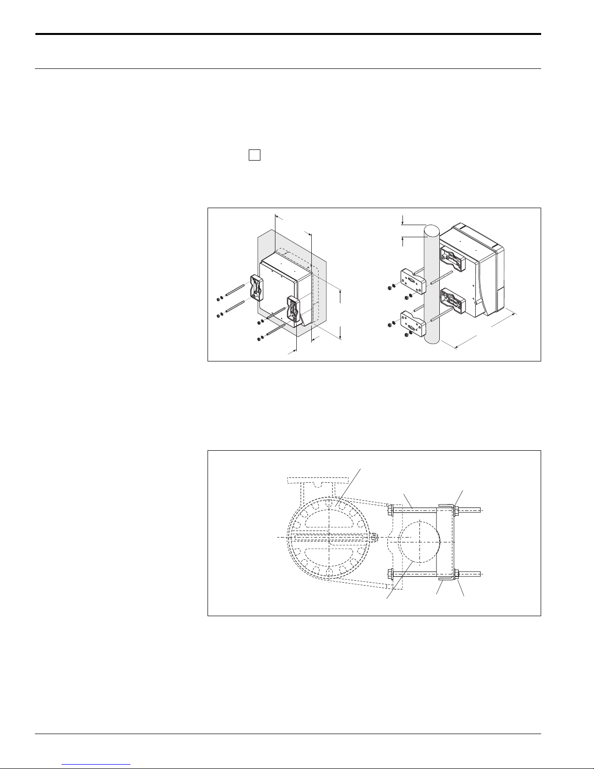
Promag 50/53 field housing mounting kit
DK8WM -
1 Transmitter type
A Panel/wall/pipe mount (2” pipe) hardware
B Wall/pipe mount for remote field housing
+0.02
-0.02
8.27"
+0.5
-0.5
(210 )
4.33"
(110)
9.65"
(245 )
+0.02
-0.02
+0.5
-0.5
Ø 2"
(50)
6.10"
(155)
DK8WM - A
Mounting set for wall / panel enclosure, 3/4” to 2-3/4”
pipe
Includes:
4 mounting plates
4 threaded rods, M6 x 150 mm
4 washers
4 nuts, M6
Remote Transmitter Housing
Bolt
3/4" to 3" Pipe
Mounting Plate
DK8WM - B
Mounting set for wall / pipe mount remote field enclosure, 3/4” to 3” pipe
Includes:
Mounting plate
4 bolts, M8 x 150 mm
4 washers
4 nuts, M8
Washer
Nut
Endress+Hauser30
Page 31

Promag 50/53 W
Supplemental documentation
Promag System Information (SI 028D/24/ae)
Promag 50/53 P Technical Information (TI 047D/24/ae)
Promag 50/53 H Technical Information (TI 048D/24/ae)
Promag 50 Operating Instructions (BA 046D/06/en and BA 049D/06/en)
Promag 53 Operating Instructions (BA 047D/06/en and BA 048D/06/en)
Hazardous Area Approvals Documentation (FM, CSA, ATEX, etc.)
Endress+Hauser 31
Page 32

For application and selection assistance,
in the U.S. call 888-ENDRESS
For total support of your installed base, 24 hours
a day, in the U.S. call 800-642-8737
Visit us on our web site, www.us.endress.com
United States
Endress+Hauser, Inc.
2350 Endress Place
Greenwood, IN 46143
Phone: (317) 535-7138
888-ENDRESS
FAX: (317) 535-8498
TI 046D/24/ae/05.04
© 2004 Endress+Hauser, Inc.
Canada
Endress+Hauser Canada
1075 Sutton Drive
Burlington, ON L7L 5Z8
Phone: (905) 681-9292
800-668-3199
FAX: (905) 681-9444
Mexico
Endress+Hauser
Paseo del Pedregal No. 610
Col. Jardines del Pedregal
01900, Mexico D .F.
Mexico
Phone: (525) 568-2405
FAX: (525) 568-7459
Endress+Hauser
The Power ofKnow How
 Loading...