

Page 1
Products Solutions Services
Brief Operating Instructions
Proline Promag
Part 1 of 2
Electromagnetic sensor
These Instructions are Brief Operating Instructions; they are
not a substitute for the Operating Instructions pertaining to
the device.
These Brief Operating Instructions contain all of the
information on the sensor. Please also follow the Brief
Operating Instructions for the transmitter during
commissioning → 3.
KA01216D/06/EN/03.17
71360077
Page 2
Proline Promag
2 Endress+Hauser
1.
Order code:
Ext. ord. cd.:
Ser. no.:
www.endress.com/deviceviewer Endress+Hauser Operations App
XXXXXXXXXXXX
XXXXX-XXXXXX
XXX.XXXX.XX
Serial number
2.
3.
A0023555
Page 3

Proline Promag Brief Operating Instructions for the device
Endress+Hauser 3
Brief Operating Instructions for the device
The device consists of a transmitter and a sensor.
The process of commissioning these two components is described in two separate manuals:
• Sensor Brief Operating Instructions
• Transmitter Brief Operating Instructions
Please refer to both Brief Operating Instructions when commissioning the device as the
contents of the manuals complement one another:
Sensor Brief Operating Instructions
The Sensor Brief Operating Instructions are aimed at specialists with responsibility for
installing the measuring device.
• Incoming acceptance and product identification
• Storage and transport
• Installation
Transmitter Brief Operating Instructions
The Transmitter Brief Operating Instructions are aimed at specialists with responsibility for
commissioning, configuring and parameterizing the measuring device (until the first
measured value).
• Product description
• Installation
• Electrical connection
• Operation options
• System integration
• Commissioning
• Diagnostic information
Additional device documentation
These Brief Operating Instructions are the Sensor Brief Operating Instructions.
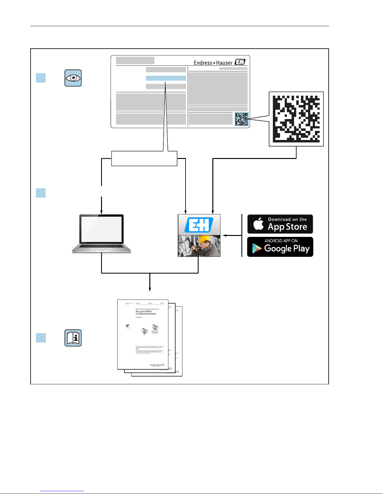
The "Transmitter Brief Operating Instructions" are available via:
• Internet: www.endress.com/deviceviewer
• Smart phone/tablet: Endress+Hauser Operations App
Detailed information about the device can be found in the Operating Instructions and the
other documentation:
• Internet: www.endress.com/deviceviewer
• Smart phone/tablet: Endress+Hauser Operations App
Page 4

Table of contents Proline Promag
4 Endress+Hauser
Table of contents
1 Document information ............................................................ 5
1.1 Symbols used ......................................................................... 5
2 Basic safety instructions .......................................................... 7
2.1 Requirements for the personnel ............................................................7
2.2 Designated use ........................................................................ 7
2.3 Workplace safety ...................................................................... 8
2.4 Operational safety ......................................................................8
2.5 Product safety .........................................................................8
2.6 IT security ............................................................................9
3 Incoming acceptance and product identification ...................................9
3.1 Incoming acceptance .................................................................... 9
3.2 Product identification .................................................................. 10
4 Storage and transport ........................................................... 11
4.1 Storage conditions .................................................................... 11
4.2 Transporting the product ................................................................11
5 Installation ...................................................................... 13
5.1 Installation conditions ..................................................................13
5.2 Mounting the measuring device ...........................................................20
5.3 Post-installation check ................................................................. 32
6 Disposal ......................................................................... 32
6.1 Removing the measuring device .......................................................... 32
6.2 Disposing of the measuring device ......................................................... 32
7 Appendix ........................................................................ 33
7.1 Screw tightening torques ................................................................ 33
Page 5
Proline Promag Document information
Endress+Hauser 5
1 Document information
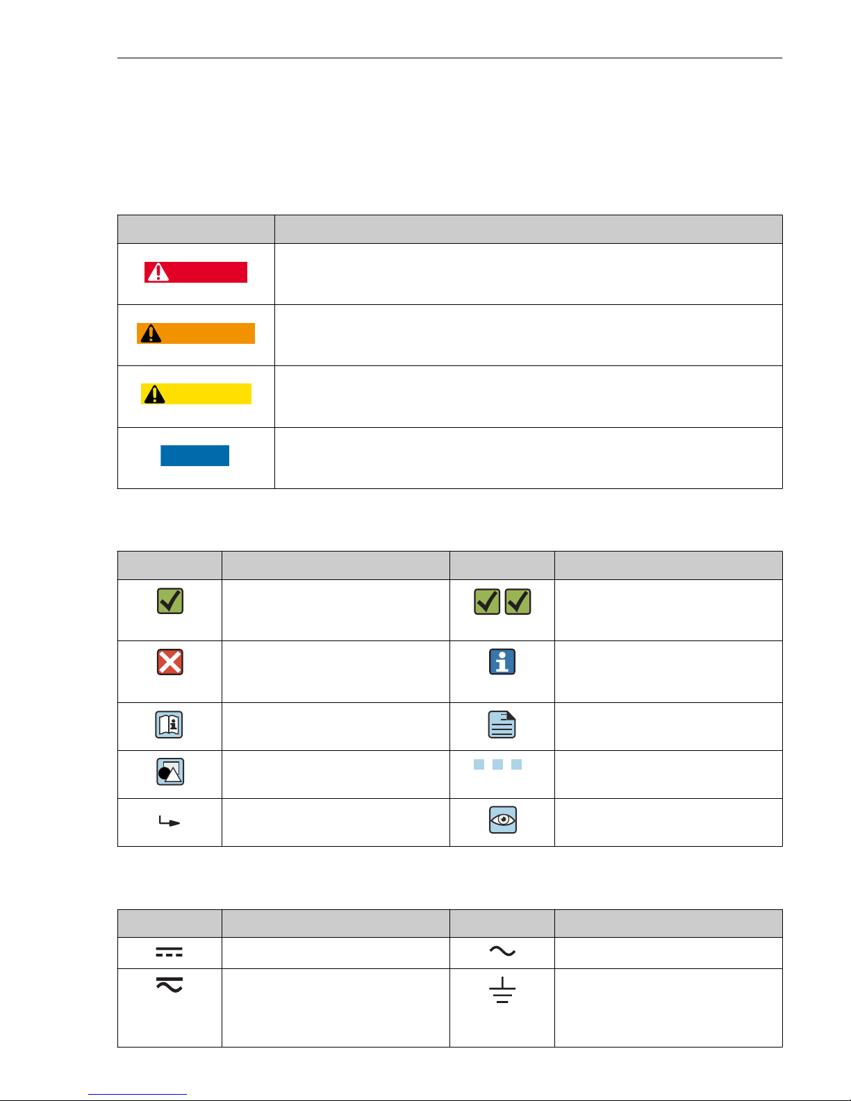
1.1 Symbols used
1.1.1 Safety symbols
Symbol Meaning
DANGER
DANGER!
This symbol alerts you to a dangerous situation. Failure to avoid this situation will result in
serious or fatal injury.
WARNING
WARNING!
This symbol alerts you to a dangerous situation. Failure to avoid this situation can result in
serious or fatal injury.
CAUTION
CAUTION!
This symbol alerts you to a dangerous situation. Failure to avoid this situation can result in
minor or medium injury.
NOTICE
NOTE!
This symbol contains information on procedures and other facts which do not result in
personal injury.
1.1.2 Symbols for certain types of information
Symbol Meaning Symbol Meaning
Permitted
Procedures, processes or actions that
are permitted.
Preferred
Procedures, processes or actions that
are preferred.
Forbidden
Procedures, processes or actions that
are forbidden.
Tip
Indicates additional information.
Reference to documentation
A
Reference to page
Reference to graphic
1.
, 2., 3.… Series of steps
Result of a step Visual inspection
1.1.3 Electrical symbols
Symbol Meaning Symbol Meaning
Direct current Alternating current
Direct current and alternating current Ground connection
A grounded terminal which, as far as
the operator is concerned, is grounded
via a grounding system.
Page 6
Document information Proline Promag
6 Endress+Hauser
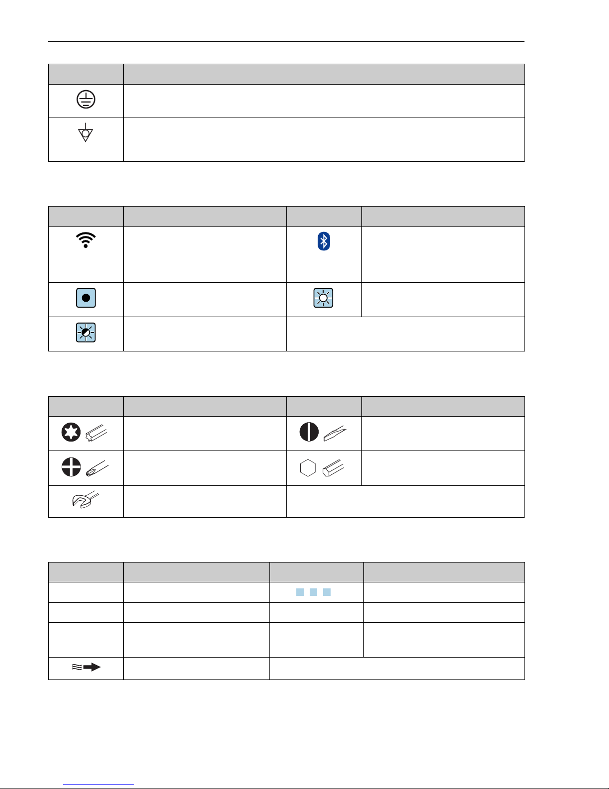
Symbol Meaning
Protective ground connection
A terminal which must be connected to ground prior to establishing any other connections.
Equipotential connection
A connection that has to be connected to the plant grounding system: This may be a potential
equalization line or a star grounding system depending on national or company codes of practice.
1.1.4 Communication symbols
Symbol Meaning Symbol Meaning
Wireless Local Area Network
(WLAN)
Communication via a wireless, local
network.
Bluetooth
Wireless data transmission between
devices over a short distance.
LED
Light emitting diode is off.
LED
Light emitting diode is on.
LED
Light emitting diode is flashing.
1.1.5 Tool symbols
Symbol Meaning Symbol Meaning
Torx screwdriver Flat blade screwdriver
Cross-head screwdriver Allen key
Open-ended wrench
1.1.6 Symbols in graphics
Symbol Meaning Symbol Meaning
1, 2, 3,... Item numbers
1.
, 2., 3.… Series of steps
A, B, C, ... Views A-A, B-B, C-C, ... Sections
-
Hazardous area
.
Safe area (non-hazardous area)
Flow direction
Page 7

Proline Promag Basic safety instructions
Endress+Hauser 7
2 Basic safety instructions
2.1 Requirements for the personnel
The personnel must fulfill the following requirements for its tasks:
‣
Trained, qualified specialists must have a relevant qualification for this specific function
and task.
‣
Are authorized by the plant owner/operator.
‣
Are familiar with federal/national regulations.
‣
Before starting work, read and understand the instructions in the manual and
supplementary documentation as well as the certificates (depending on the application).
‣
Follow instructions and comply with basic conditions.
2.2 Designated use
Application and media
The measuring device is only suitable for flow measurement of liquids with a minimum
conductivity of 5 μS/cm(Promag 100, 300, 500) or 20 μS/cm (Promag 200).
Depending on the version ordered, the measuring device can also measure potentially
explosive, flammable, poisonous and oxidizing media.
Measuring devices for use in hazardous areas, in hygienic applications or where there is an
increased risk due to process pressure, are labeled accordingly on the nameplate.
To ensure that the measuring device remains in proper condition for the operation time:
‣
Only use the measuring device in full compliance with the data on the nameplate and the
general conditions listed in the Operating Instructions and supplementary documentation.
‣
Based on the nameplate, check whether the ordered device is permitted for the intended
use in the hazardous area (e.g. explosion protection, pressure vessel safety).
‣
Use the measuring device only for media to which the process-wetted materials are
sufficiently resistant.
‣
If the measuring device is not operated at atmospheric temperature, compliance with the
relevant basic conditions specified in the associated device documentation is absolutely
essential: "Documentation" section..
‣
Protect the measuring device permanently against corrosion from environmental
influences.
Promag 400
The measuring device is optionally tested in accordance with OIML R49: 2006 and has
an EC type-examination certificate according to Measuring Instruments Directive
2004/22/EC (MID) for service subject to legal metrological control ("custody transfer")
for cold water (Annex MI‐001).
The permitted fluid temperature in these applications is 0 to 50 °C (32 to 122 °F).
Incorrect use
Non-designated use can compromise safety. The manufacturer is not liable for damage caused
by improper or non-designated use.
Page 8

Basic safety instructions Proline Promag
8 Endress+Hauser
L
WARNING
Danger of breakage due to corrosive or abrasive fluids!
‣
Verify the compatibility of the process fluid with the sensor material.
‣
Ensure the resistance of all fluid-wetted materials in the process.
‣
Keep within the specified pressure and temperature range.
NOTICE
Verification for borderline cases:
‣
For special fluids and fluids for cleaning, Endress+Hauser is glad to provide assistance in
verifying the corrosion resistance of fluid-wetted materials, but does not accept any
warranty or liability as minute changes in the temperature, concentration or level of
contamination in the process can alter the corrosion resistance properties.
Residual risks
L
WARNING
The electronics and the medium may cause the surfaces to heat up. This presents a burn
hazard!
‣
For elevated fluid temperatures, ensure protection against contact to prevent burns.
2.3 Workplace safety
For work on and with the device:
‣
Wear the required personal protective equipment according to federal/national
regulations.
For welding work on the piping:
‣
Do not ground the welding unit via the measuring device.
If working on and with the device with wet hands:
‣
Due to the increased risk of electric shock, gloves must be worn.
2.4 Operational safety
Risk of injury!
‣
Operate the device in proper technical condition and fail-safe condition only.
‣
The operator is responsible for interference-free operation of the device.
Environmental requirements Promag 400
If a plastic transmitter housing is permanently exposed to certain steam and air mixtures, this
can damage the housing.
‣
If you are unsure, please contact your Endress+Hauser Sales Center for clarification.
‣
If used in an approval-related area, observe the information on the nameplate.
2.5 Product safety
This measuring device is designed in accordance with good engineering practice to meet stateof-the-art safety requirements, has been tested, and left the factory in a condition in which it
is safe to operate.
Page 9
Proline Promag Incoming acceptance and product identification
Endress+Hauser 9
It meets general safety standards and legal requirements. It also complies with the EU
directives listed in the device-specific EU Declaration of Conformity. Endress+Hauser confirms
this by affixing the CE mark to the device.
2.6 IT security
We only provide a warranty if the device is installed and used as described in the Operating
Instructions. The device is equipped with security mechanisms to protect it against any
inadvertent changes to the device settings.
IT security measures in line with operators' security standards and designed to provide
additional protection for the device and device data transfer must be implemented by the
operators themselves.
3 Incoming acceptance and product identification
3.1 Incoming acceptance
A0028673
1
2
1
2
A0029314
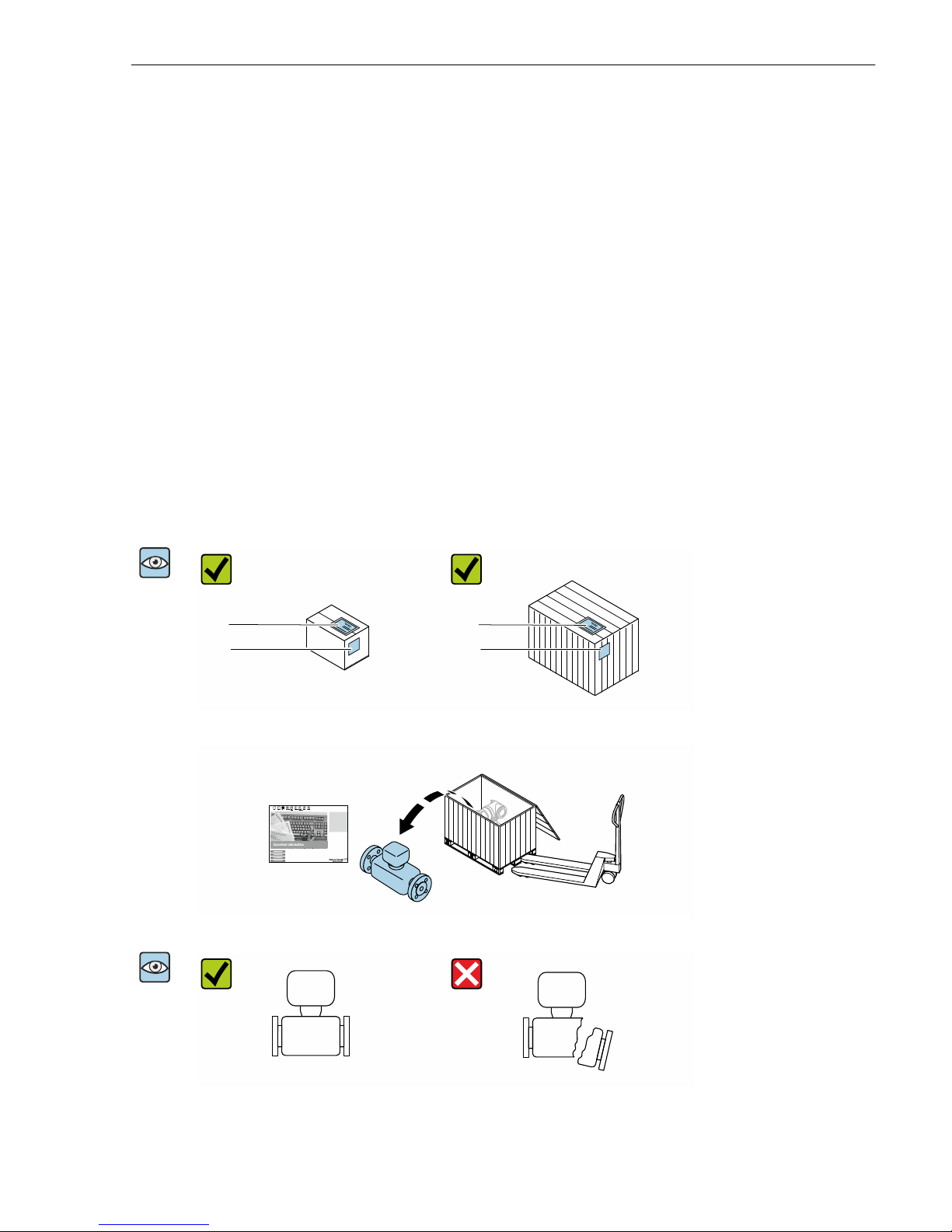
Are the order codes on
the delivery note (1)
and the product sticker
(2) identical?
A0029315
A0028673
A0029316
Are the goods
undamaged?
Page 10
Incoming acceptance and product identification Proline Promag
10 Endress+Hauser
A0028673
Order code:
Ser. no.:
Ext. ord. cd.:
i
i
Date:
A0029317
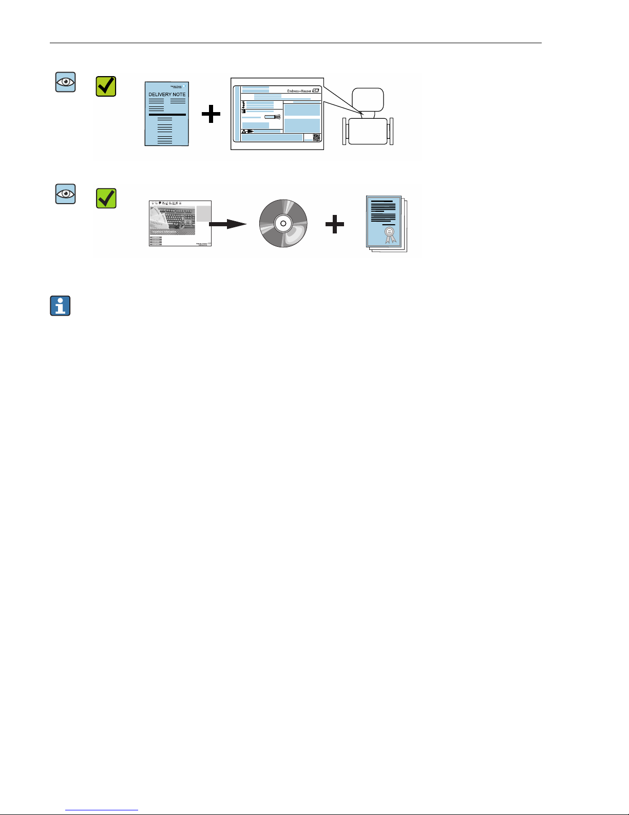
Do the nameplate data
match the ordering
information on the
delivery note?
A0028673
A0029318
Is the CD-ROM with the
Technical
Documentation
(depends on device
version) and documents
present?
• If one of the conditions is not satisfied, contact your Endress+Hauser Sales Center.
• Depending on the device version, the CD-ROM might not be part of the delivery! The
Technical Documentation is available via the Internet or via the Endress+Hauser
Operations App.
3.2 Product identification
The following options are available for identification of the measuring device:
• Nameplate specifications
• Order code with breakdown of the device features on the delivery note
• Enter serial numbers from nameplates in W@M Device Viewer
(www.endress.com/deviceviewer): All information about the measuring device is displayed.
• Enter the serial number from the nameplates into the Endress+Hauser Operations App or
scan the 2-D matrix code (QR code) on the nameplate with the Endress+Hauser Operations
App: all the information for the measuring device is displayed.
Page 11
Proline Promag Storage and transport
Endress+Hauser 11
Order code:
Ext. ord. cd.:
Ser. no.:
Order code:
Ext. ord. cd.:
Ser. no.:
1
2
3
4
A0030196
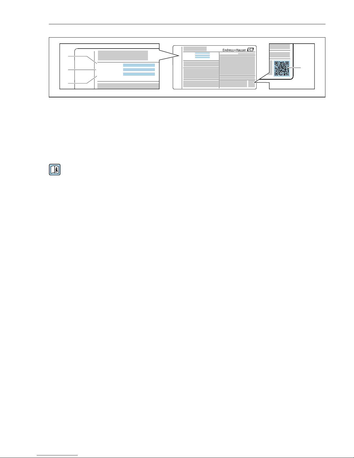
1 Example of a nameplate
1 Order code
2 Serial number (Ser. no.)
3 Extended order code (Ext. ord. cd.)
4 2-D matrix code (QR code)
For detailed information on the breakdown of the specifications on the nameplate, see
the Operating Instructions for the device .
4 Storage and transport
4.1 Storage conditions
Observe the following notes for storage:
‣
Store in the original packaging to ensure protection from shock.
‣
Do not remove protective covers or protective caps installed on process connections. They
prevent mechanical damage to the sealing surfaces and contamination in the measuring
tube.
‣
Protect from direct sunlight to avoid unacceptably high surface temperatures.
‣
Select a storage location where moisture cannot collect in the measuring device as fungus
and bacteria infestation can damage the lining.
‣
Store in a dry and dust-free place.
‣
Do not store outdoors.
4.2 Transporting the product
Transport the measuring device to the measuring point in the original packaging.
Page 12
Storage and transport Proline Promag
12 Endress+Hauser
A0029252
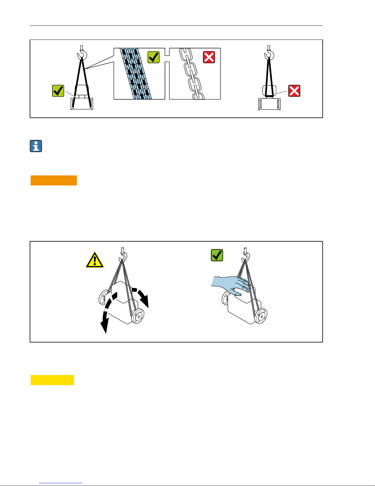
Do not remove protective covers or caps installed on process connections. They prevent
mechanical damage to the sealing surfaces and contamination in the measuring tube.
4.2.1 Measuring devices without lifting lugs
L
WARNING
Center of gravity of the measuring device is higher than the suspension points of the
webbing slings.
Risk of injury if the measuring device slips.
‣
Secure the measuring device against slipping or turning.
‣
Observe the weight specified on the packaging (stick-on label).
A0029214
4.2.2 Measuring devices with lifting lugs
L
CAUTION
Special transportation instructions for devices with lifting lugs
‣
Only use the lifting lugs fitted on the device or flanges to transport the device.
‣
The device must always be secured at two lifting lugs at least.
4.2.3 Transporting with a fork lift
If transporting in wood crates, the floor structure enables the crates to be lifted lengthwise or
at both sides using a forklift.
Page 13
Proline Promag Installation
Endress+Hauser 13
L
CAUTION
Risk of damaging the magnetic coil
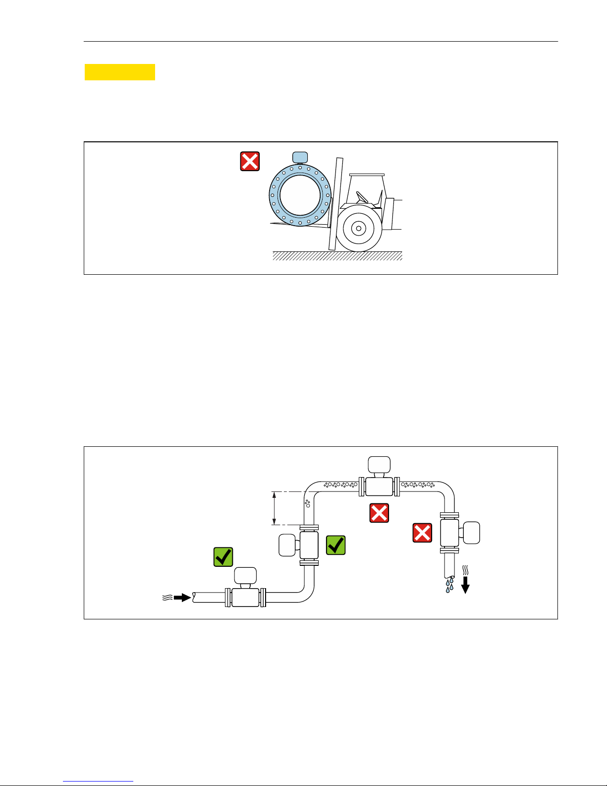
‣
If transporting by forklift, do not lift the sensor by the metal casing.
‣
This would buckle the casing and damage the internal magnetic coils.
A0029319
5 Installation
5.1 Installation conditions
5.1.1 Mounting position
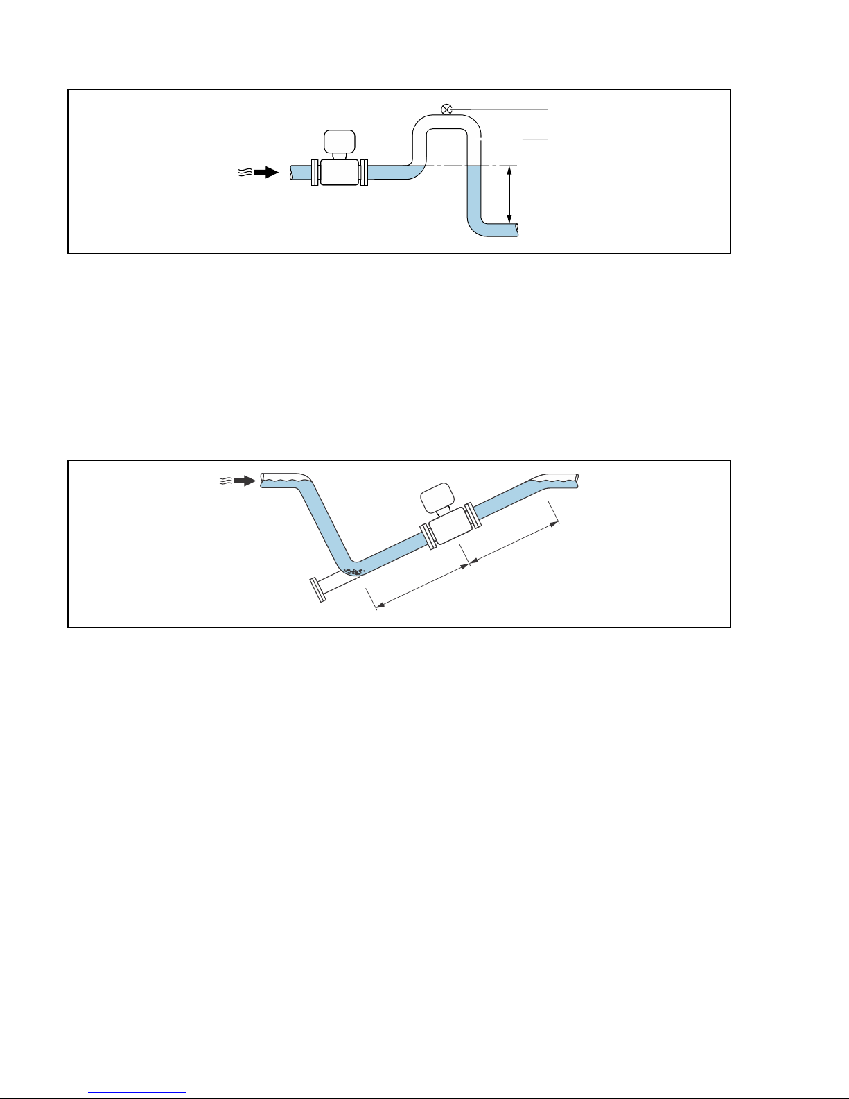
Mounting location
h
A0029343
h ≥ 2 × DN
Installation in down pipes
Install a siphon with a vent valve downstream of the sensor in down pipes whose length h ≥
5 m (16,4 ft). This precaution is to avoid low pressure and the consequent risk of damage to
the measuring tube. This measure also prevents the system losing prime.
Page 14
Installation Proline Promag
14 Endress+Hauser
h
2
1
A0028981
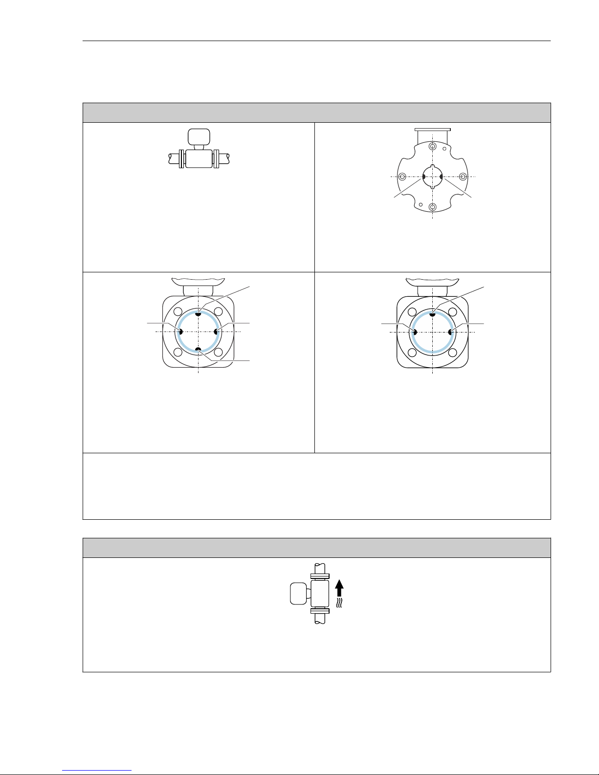
2 Installation in a down pipe
1 Vent valve
2 Pipe siphon
h Length of down pipe
Installation in partially filled pipes
A partially filled pipe with a gradient necessitates a drain-type configuration.
2 x DN³
5 x DN³
A0029257
Orientation
The direction of the arrow on the sensor nameplate helps you to install the sensor according
to the flow direction.
Page 15
Proline Promag Installation
Endress+Hauser 15
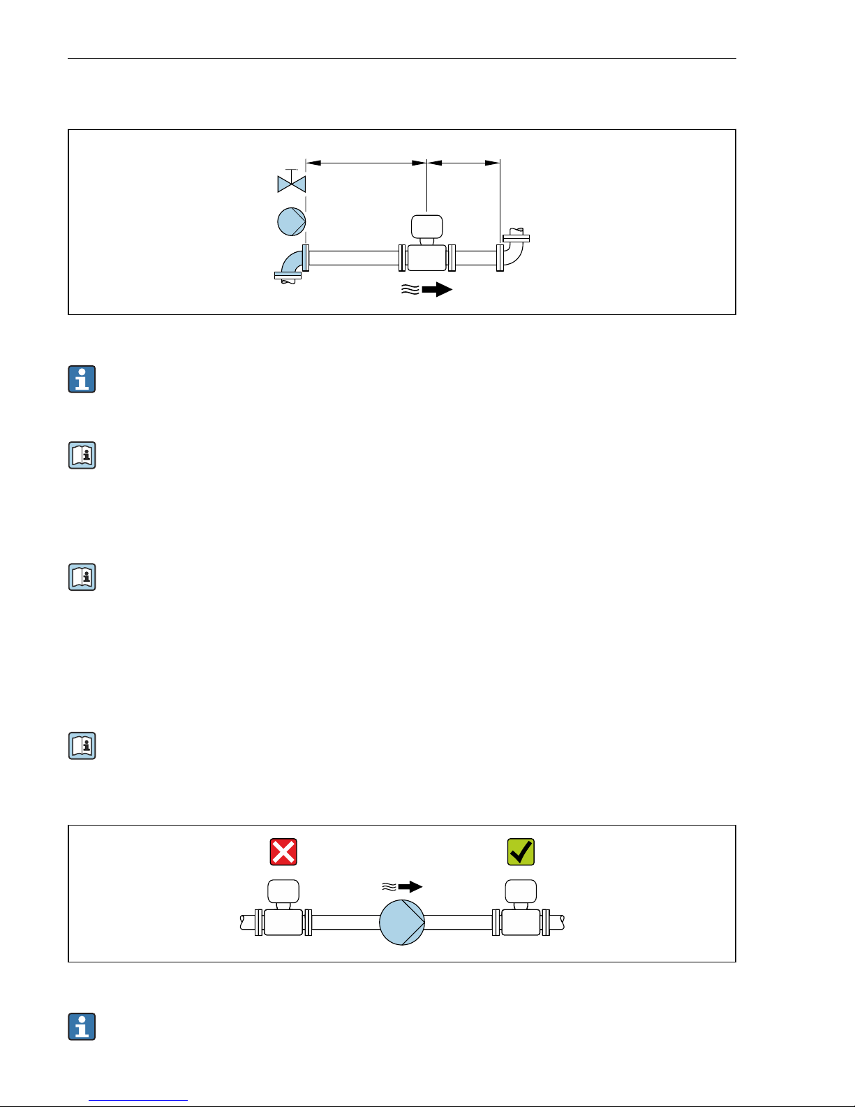
An optimum orientation position helps avoid gas and air accumulations and deposits in the
measuring tube.
Horizontal orientation (transmitter at top)
A0015589
1 1
A0017195
3 Promag D
1 Measuring electrodes for signal detection
1
2
3
A0029344
4 Promag E, L, P, W
1 EPD electrode for empty pipe detection
2 Measuring electrodes for signal detection
3 Reference electrode for potential equalization
1
22
A0028998
5 Promag H
1 EPD electrode for empty pipe detection
2 Measuring electrodes for signal detection
The measuring electrode plane must be horizontal. This prevents brief insulation of the two measuring electrodes by
entrained air bubbles.
Empty pipe detection (Promag E, H, L, P, W) only works if the transmitter housing is pointing upwards as otherwise
there is no guarantee that the empty pipe detection function will actually respond to a partially filled or empty
measuring tube.
Vertical orientation
A0015591
Optimum for self-emptying pipe systems.
Optimum if using empty pipe detection (Promag E, H, L, P, W).
Page 16
Installation Proline Promag
16 Endress+Hauser
Inlet and outlet runs
≥ 5 x DN
≥ 2 x DN
A0028997
Promag W 400
To keep within the in-service maximum permissible errors for custody transfer no
additional requirements apply with regard to the graphic illustrated above.
For the dimensions and installation lengths of the device, see the "Technical Information"
document, "Mechanical construction" section
5.1.2 Requirements from environment and process
Ambient temperature range
For detailed information on the ambient temperature range, see the Operating
Instructions for the device.
If operating outdoors:
• Install the measuring device in a shady location.
• Avoid direct sunlight, particularly in warm climatic regions.
• Avoid direct exposure to weather conditions.
Temperature tables
For detailed information on the temperature tables, see the separate document entitled
"Safety Instructions" (XA) for the device.
System pressure
A0028777
Furthermore, install pulse dampers if reciprocating, diaphragm or peristaltic pumps are
used.
Page 17
Proline Promag Installation
Endress+Hauser 17
Thermal insulation Promag P 300/500
Pipes generally have to be insulated if they carry very hot fluids to avoid energy losses and
prevent accidental contact with pipes at temperatures that could cause injury. Guidelines
regulating the insulation of pipes have to be taken into account.
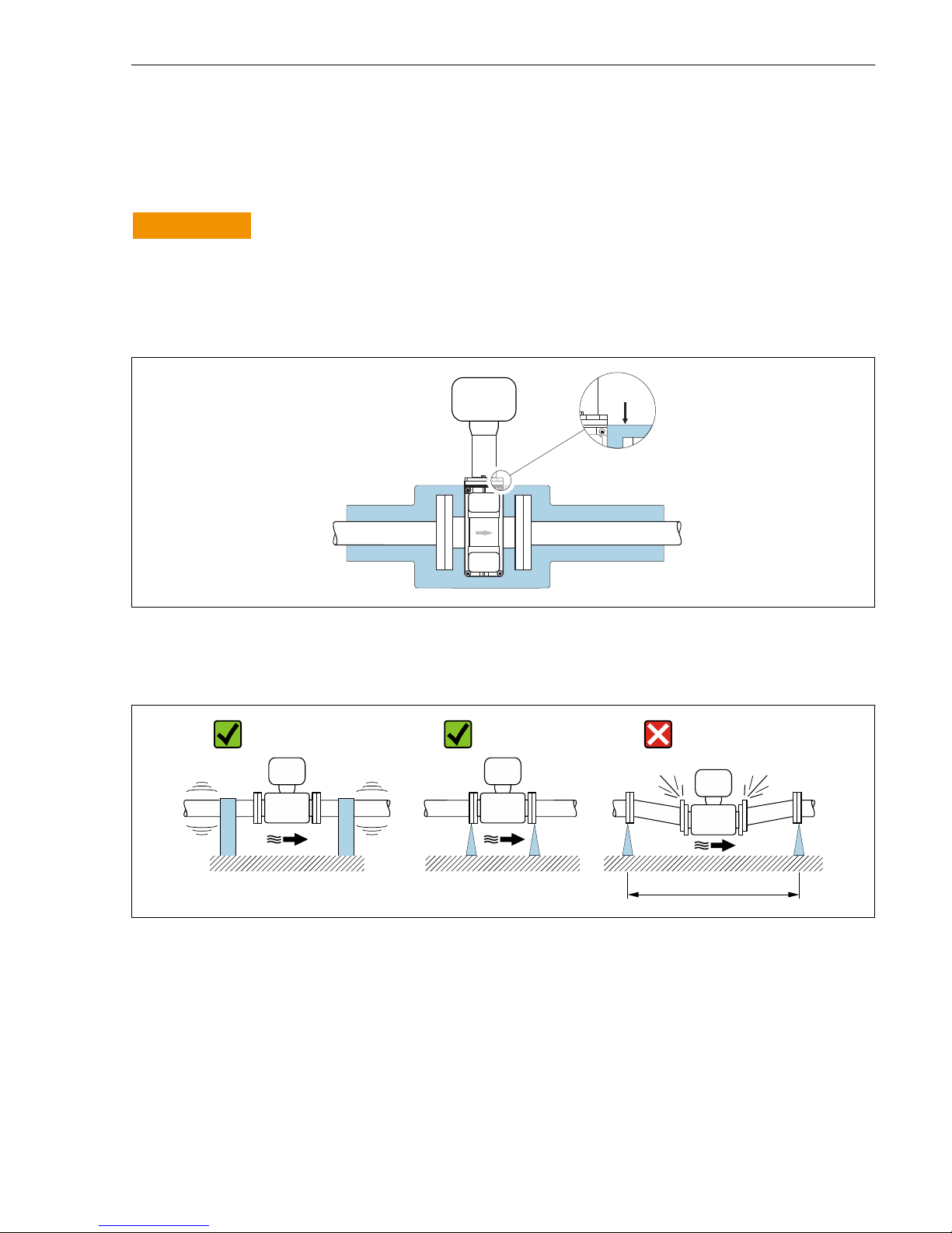
L
WARNING
Electronics overheating on account of thermal insulation!
‣
The housing support dissipates heat and its entire surface area must remain uncovered.
Make sure that the sensor insulation does not extend past the top of the two sensor halfshells.
max.
A0031216
Vibrations
L
A0029004
6 Measures to avoid device vibrations (L > 10 m (33 ft))
Page 18
Installation Proline Promag
18 Endress+Hauser
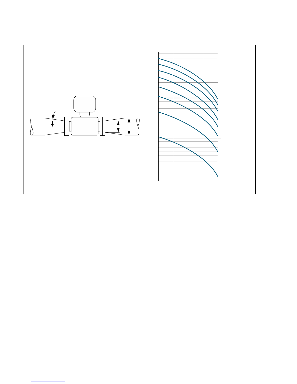
Adapters
100
10
0.5
d / D
[mbar]
0.6 0.7 0.8 0.9
1 m/s
2 m/s
3 m/s
4 m/s
5 m/s
6 m/s
7 m/s
8 m/s
1
D
d
max. 8°
A0029002
5.1.3 Special mounting instructions
Promag 200, 400
Display protection
‣
To ensure that the optional display guard can be easily opened, maintain the following
minimum head clearance: 350 mm (13,8 in)
Promag L 400
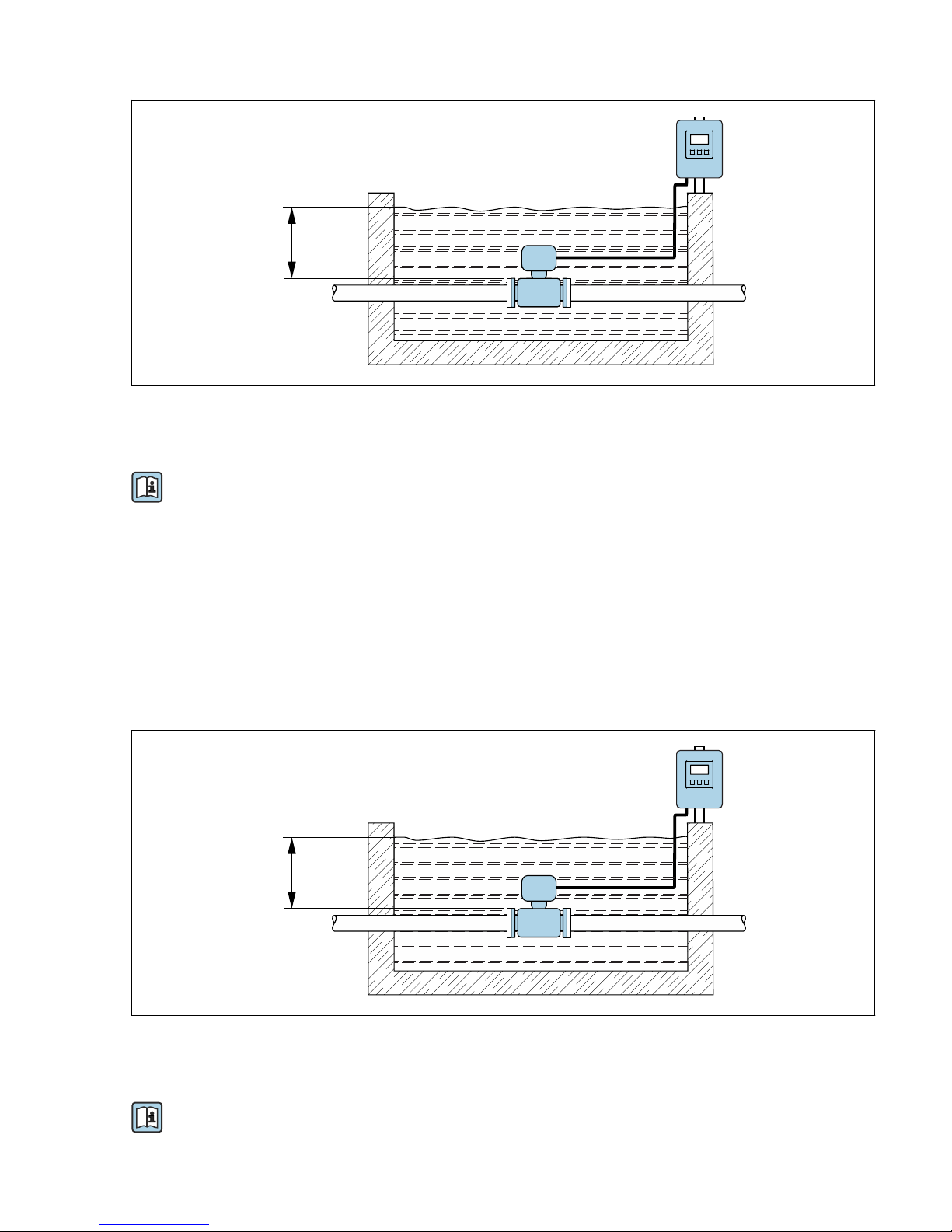
Temporary immersion in water
A remote version with IP67 protection, Type 6 is optionally available for temporary immersion
in water for up to 168 hours at ≤ 3 m (10 ft) or in exceptional cases for use for up to 48 hours
at ≤ 10 m (30 ft).
Compared with the standard degree of protection IP67, Type 4X enclosure, the version IP67,
Type 6 enclosure has been designed to withstand short-term or temporary flooding.
Page 19
Proline Promag Installation
Endress+Hauser 19
≤ ≤
3 ( 10)
A0029320
7 Engineering unit in m(ft)
For detailed information on replacing the cable gland on the connection housing, see the
Transmitter Brief Operating Instructions.
Promag W 400, W 500
Permanent immersion in water
A fully welded remote version with IP68 protection is optionally available for permanent
immersion in water ≤ 3 m (10 ft) or in exceptional cases for use for up to 48 hours at ≤
10 m (30 ft). The measuring device meets the requirements of corrosion categories C5-M and
Im1/Im2/Im3. The fully welded design along with the connection compartment sealing
system ensure that moisture cannot enter the measuring device.
≤ ≤
3 ( 10)
A0029320
8 Engineering unit in m(ft)
For detailed information on replacing the cable gland on the connection housing, see the
Transmitter Brief Operating Instructions.
Page 20
Installation Proline Promag
20 Endress+Hauser
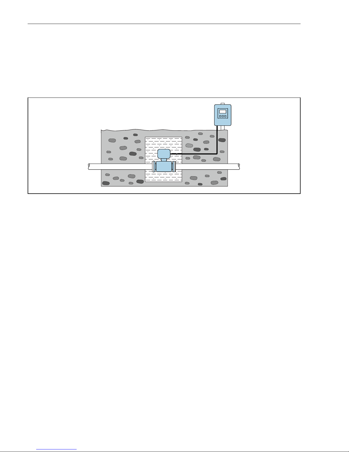
Buried applications
A remote version with IP68 protection is optionally available for buried applications. The
measuring device meets the requirements of certified corrosion protection Im1/Im2/Im3
according to EN ISO 12944. It can be used directly in buried applications without having to
take any additional precautions for the measuring device. The device is mounted in
accordance with the usual regional installation regulations (e.g. EN DIN 1610).
A0029321
5.2 Mounting the measuring device
5.2.1 Required tools
For transmitter
• For turning the transmitter housing: Open-ended wrench8 mm
• For opening the securing clamps: Allen key3 mm
• For turning the transmitter housing: Open-ended wrench8 mm
• For opening the securing clamps: Allen key3 mm
• Torque wrench
• For wall mounting:
Open-ended wrench for hexagonal screw max. M5
• For pipe mounting:
– Open-ended wrench AF 8
– Phillips head screwdriver PH 2
• For turning the transmitter housing (compact version):
– Phillips head screwdriver PH 2
– Torx screwdriver TX 20
– Open-ended wrench AF 7
Page 21

Proline Promag Installation
Endress+Hauser 21
For mounting on a post:
• Proline 500 – digital transmitter
– Open-ended wrench AF 10
– Torx screwdriver TX 25
• Proline 500 transmitter
Open-ended wrench AF 13
• Open-ended wrench AF 13
For wall mounting:
Drill with drill bit ⌀ 6.0 mm
For sensor
For flanges and other process connections:
• Screws, nuts, seals etc. are not included in the scope of supply and must be provided by the
customer.
• Appropriate mounting tools
5.2.2 Preparing the measuring device
1. Remove all remaining transport packaging.
2. Remove any protective covers or protective caps present from the sensor.
3. Remove stick-on label on the electronics compartment cover.
5.2.3 Mounting the sensor
L
WARNING
An electrically conductive layer could form on the inside of the measuring tube!
Risk of measuring signal short circuit.
‣
Ensure that the inside diameters of the gaskets are greater than or equal to that of the
process connections and piping.
‣
Ensure that the gaskets are clean and undamaged.
‣
Install the gaskets correctly.
‣
Do not use electrically conductive sealing compounds such as graphite.
L
WARNING
Danger due to improper process sealing!
‣
Ensure that the inside diameters of the gaskets are greater than or equal to that of the
process connections and piping.
‣
Ensure that the gaskets are clean and undamaged.
‣
Install the gaskets correctly.
1. Ensure that the direction of the arrow on the sensor matches the flow direction of the
medium.
2. To ensure compliance with device specifications, install the measuring device between
the pipe flanges in a way that it is centered in the measurement section.
3. If using ground disks, comply with the Installation Instructions provided.
4. Observe required screw tightening torques.
Page 22
Installation Proline Promag
22 Endress+Hauser
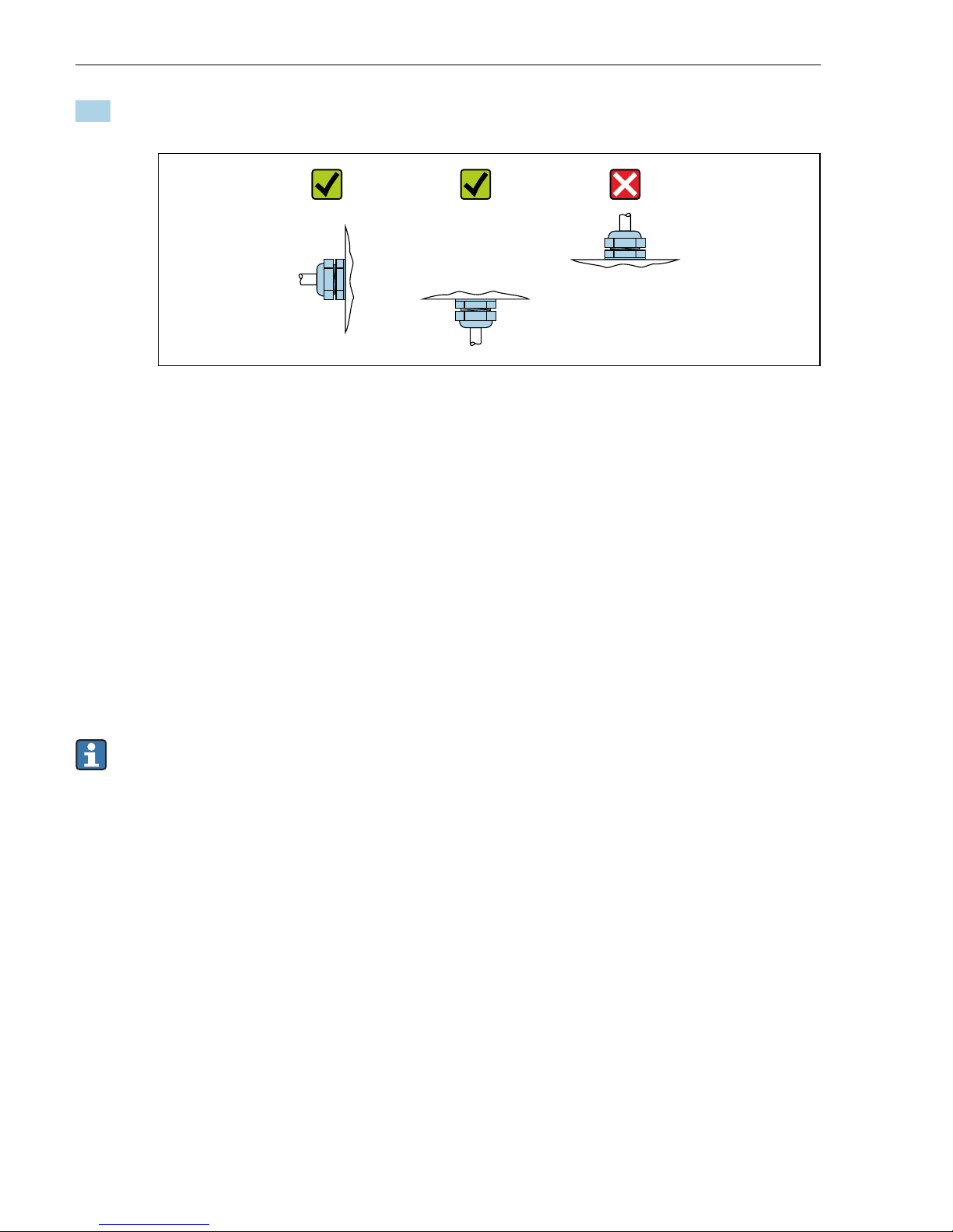
5. Install the measuring device or turn the transmitter housing so that the cable entries do
not point upwards.
A0029263
Promag D
Seals
Comply with the following instructions when installing seals:
• Use seals with a hardness rating of 70° Shore.
• For DIN flanges: only use seals according to DIN EN 1514-1.
Mounting the ground cable
For information on potential equalization and detailed mounting instructions for the use of
ground cables, see the Transmitter Brief Operating Instructions.
Mounting kit
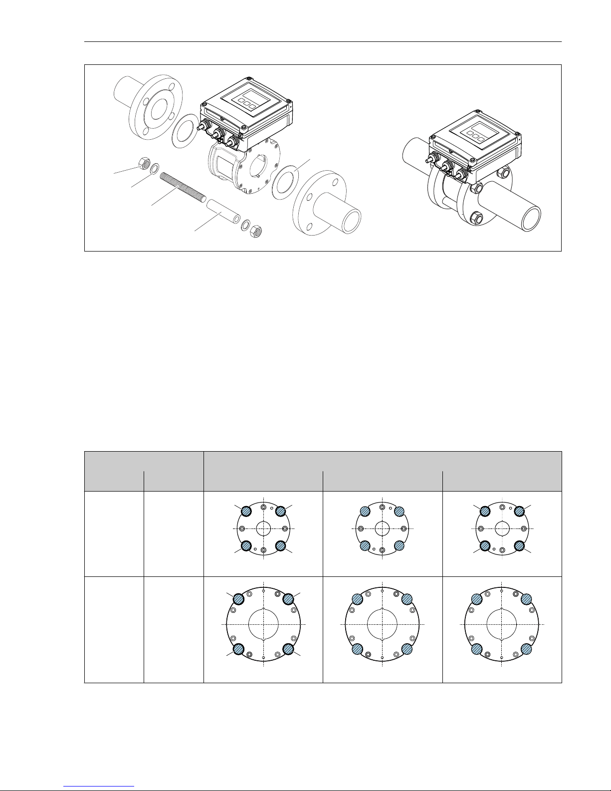
The sensor is installed between the pipe flanges using a mounting kit. The device is centered
using the recesses on the sensor. Centering sleeves are also provided depending on the flange
standard or the diameter of the pitch circle.
A mounting kit – consisting of mounting bolts, seals, nuts and washers – can be ordered
separately (see "Accessories" section ).
Page 23
Proline Promag Installation
Endress+Hauser 23
5
1
2
3
4
A0018060
9 Mounting the sensor
1 Nut
2 Washer
3 Mounting bolts
4 Centering sleeve
5 Seal
Arranging the mounting bolts and centering sleeves
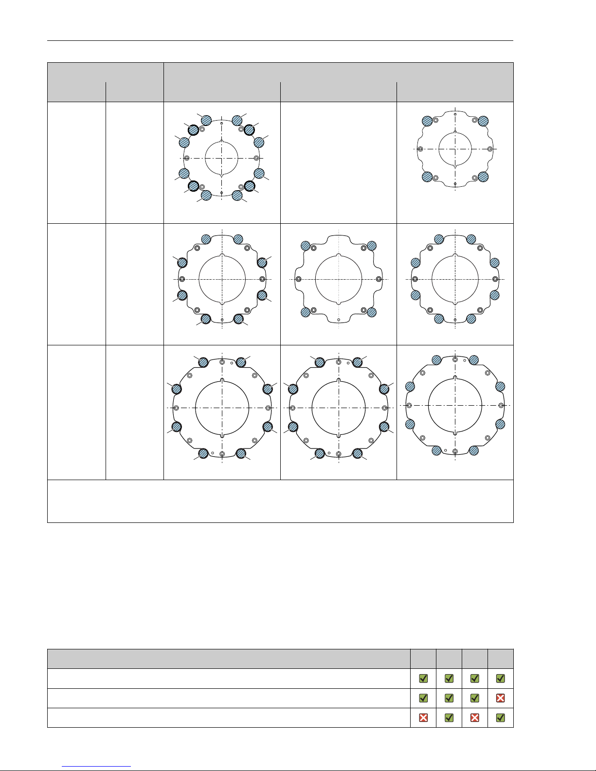
The device is centered using recesses on the sensor. The arrangement of the mounting bolts
and the use of the centering sleeves supplied depend on the nominal diameter, the flange
standard and the diameter of the pitch circle.
Nominal diameter Process connection
[mm] [in]5 EN 1092-1 (DIN 2501) ASME B16.5 JIS B2220
25…40 1…1 ½
1
1
A0029490 A0029491
1
1
A0029490
50 2
1
1
A0029492 A0029493 A0029493
Page 24
Installation Proline Promag
24 Endress+Hauser
Nominal diameter Process connection
[mm] [in]5 EN 1092-1 (DIN 2501) ASME B16.5 JIS B2220
65 2 ½
2
2 2
33
3
3
2
3
3
A0029494
–
A0029495
80 3
1
1
1 1
A0029496 A0029497 A0029498
100 4
1
11
1
11
A0029499
1
11
1
11
A0029499
A0029500
1 = Mounting bolts with centering sleeves
2 = EN (DIN) flange: 4-hole → with centering sleeves
3 = EN (DIN) flange: 8-hole → without centering sleeves
Screw tightening torques
→ 33
Promag E, L, P, W
Seals
Comply with the following instructions when installing seals:
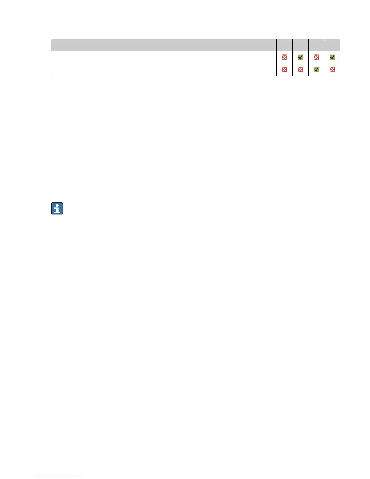
E L P W
For DIN flanges: only use seals according to DIN EN 1514-1.
For "PTFE" lining: generally additional seals are not required.
For "hard rubber" lining: additional seals are always required.
Page 25
Proline Promag Installation
Endress+Hauser 25
E L P W
For "polyurethane" lining: generally additional seals are not required.
For "PFA" lining: generally additional seals are not required.
Mounting the ground cable/ground disks
For information on potential equalization and detailed mounting instructions for the use of
ground cables/ground disks, see the Transmitter Brief Operating Instructions.
Screw tightening torques
→ 33
Promag H
Process connections
The sensor is supplied to order, with or without pre-installed process connections. Preinstalled process connections are firmly secured to the sensor by 4 or 6 hexagonal-headed
bolts.
The sensor may need to be supported or additionally secured depending on the
application and pipe length. In particular, it is absolutely essential to secure the sensor
additionally if plastic process connections are used. An appropriate wall mounting kit can
be ordered separately as an accessory from Endress+Hauser.
Seals
• In the case of metal process connections, the screws must be tightened securely. The
process connection forms a metal connection with the sensor, which ensures a defined
compression of the seal.
• In the case of plastic process connections, observe the maximum torques for lubricated
threads: 7 Nm (5,2 lbf ft); always insert a seal between the connection and the
counterflange.
• Depending on the application the seals should be replaced periodically, particularly if
molded seals are used (aseptic version)! The interval between changes depends on the
frequency of the cleaning cycles, the cleaning temperature and the medium temperature.
Replacement seals can be ordered as an accessory.
• For "PFA" lining: additional seals are always required (Promag 200).
Page 26
Installation Proline Promag
26 Endress+Hauser
A
B
C
DN 2…25
( 1")1/12…
DN 40…1 05
(1 ½… ")6
A0019804
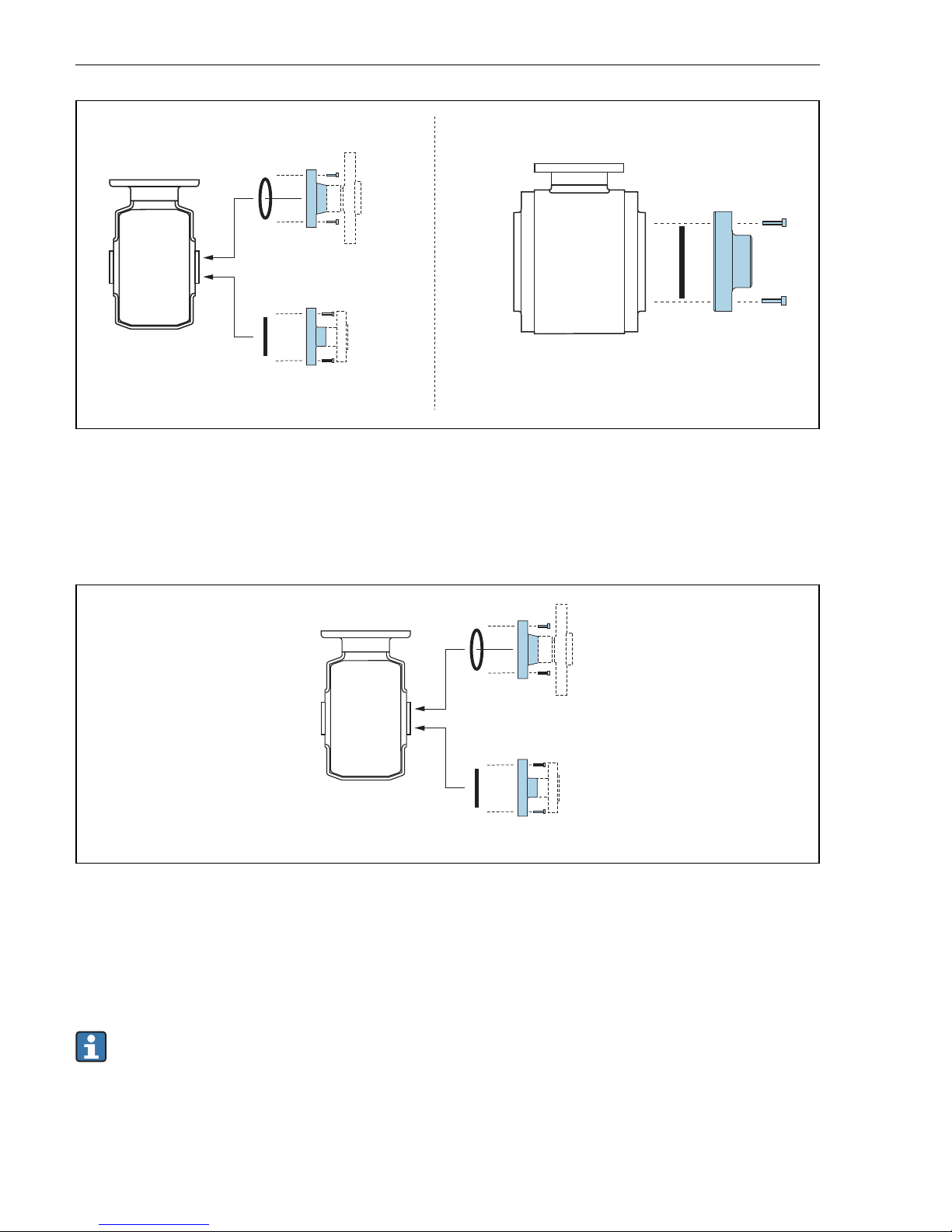
10 Seals of process connections, Promag H 100
A Process connections with O-ring seal
B Process connections with aseptic molded seal, DN 2 to 25 (1/12 to 1")
C Process connections with aseptic molded seal, DN 40 to 150 (1 ½ to 6")
A
B
DN 2…25
( 1")1/12…
A0018782
11 Seals of process connections, Promag H 200
A Process connections with O-ring seal
B Process connections with aseptic gasket seal
Mounting grounding rings, DN 2 to 25 (1/12 to 1")
For information on potential equalization, see the Transmitter Brief Operating
Instructions.
In the case of plastic process connections (e.g. flange connections or adhesive fittings),
additional ground rings must be used to ensure potential matching between the sensor and
the fluid. If grounding rings are not installed, this can affect the measuring accuracy or cause
Page 27
Proline Promag Installation
Endress+Hauser 27
the destruction of the sensor as a result of the electrochemical decomposition of the
electrodes.
• Depending on the option ordered, plastic disks are used instead of grounding rings on
some process connections. These plastic disks only act as "spacers" and do not have any
potential matching function. Furthermore, they also perform a significant sealing
function at the sensor/process connection interface. Therefore, in the case of process
connections without metal grounding rings, these plastic disks/seals should never be
removed and should always be installed!
• Grounding rings can be ordered separately as an accessory from Endress+Hauser .
When ordering make sure that the grounding rings are compatible with the material
used for the electrodes, as otherwise there is the danger that the electrodes could be
destroyed by electrochemical corrosion!
• Grounding rings, including seals, are mounted inside the process connections.
Therefore the installation length is not affected.
1
3
2
4
2
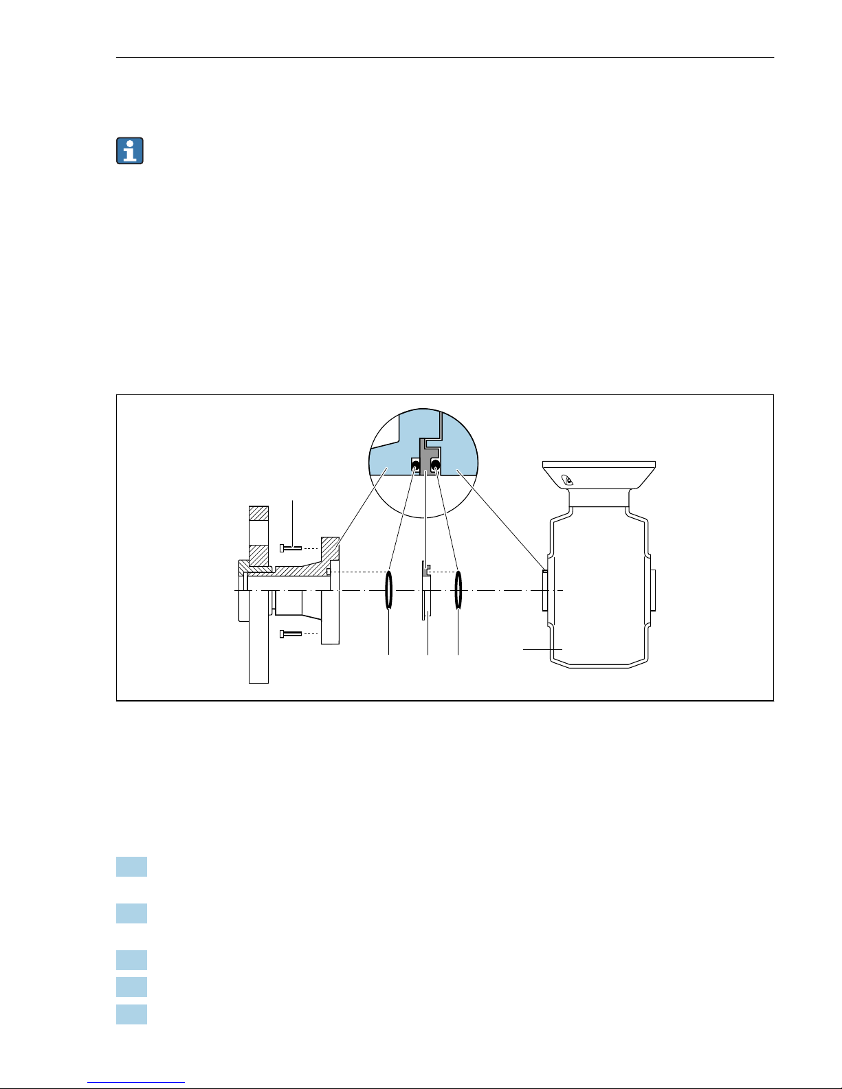
A0028971
12 Installing grounding rings
1 Hexagonal-headed bolts of process connection
2 O-ring seals
3 Grounding ring or plastic disk (spacer)
4 Sensor
1. Release the 4 or 6 hexagonal-headed bolts (1) and remove the process connection from
the sensor (4).
2. Remove the plastic disk (3), along with the two O-ring seals (2), from the process
connection.
3. Place the first O-ring seal (2) back into the groove of the process connection.
4. Fit the metal grounding ring (3) in the process connection as illustrated.
5. Place the second O-ring seal (2) into the groove of the grounding ring.
Page 28
Installation Proline Promag
28 Endress+Hauser
6. Mount the process connection back on the sensor. When doing so, make sure to observe
the maximum screw tightening torques for lubricated threads: 7 Nm (5,2 lbf ft)
Welding the sensor into the pipe (welding connections)
L
WARNING
Risk of destroying the electronics!
‣
Make sure that the welding system is not grounded via the sensor or transmitter.
1. Tack-weld the sensor to secure it in the pipe. A suitable welding aid can be ordered
separately as an accessory.
2. Release the screws on the process connection flange and remove the sensor, along with
the seal, from the pipe.
3. Weld the process connection into the pipe.
4. Reinstall the sensor in the pipe, and in doing so make sure that the seal is clean and in
the right position.
• If thin-walled pipes carrying food are welded correctly, the seal is not damaged by the
heat even when mounted. However, it is recommended to disassemble the sensor and
seal.
• It must be possible to open the pipe by approx. 8 mm (0,31 in) for disassembly.
Cleaning with pigs
It is essential to take the internal diameters of the measuring tube and process connection
into account when cleaning with pigs. All the dimensions and lengths of the sensor and
transmitter are provided in the separate "Technical Information" document.
5.2.4 Mounting the transmitter of the remote version: Promag 400,
Proline 500 – digital
L
CAUTION
Ambient temperature too high!
Danger of electronics overheating and housing deformation.
‣
Do not exceed the permitted maximum ambient temperature .
‣
If operating outdoors: Avoid direct sunlight and exposure to weathering, particularly in
warm climatic regions.
L
CAUTION
Excessive force can damage the housing!
‣
Avoid excessive mechanical stress.
Page 29
Proline Promag Installation
Endress+Hauser 29
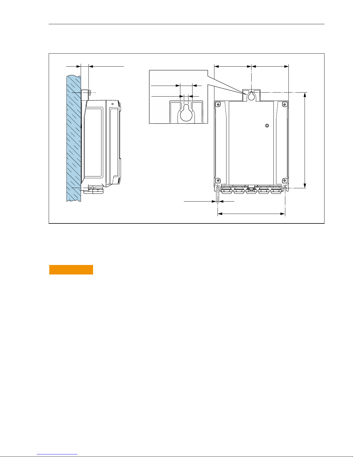
Wall mounting
149 (5.85)
211 (8.31)
=
5.8 (0.23)
17 (0.67) =
14 (0.55)
5.8 (0.23)
A0029054
13 Engineering unit mm (in)
Post mounting
L
WARNING
Excessive tightening torque applied to the fixing screws on plastic housing!
Risk of damaging the plastic transmitter.
‣
Tighten the fixing screws as per the tightening torque: 2 Nm (1,5 lbf ft)
Page 30
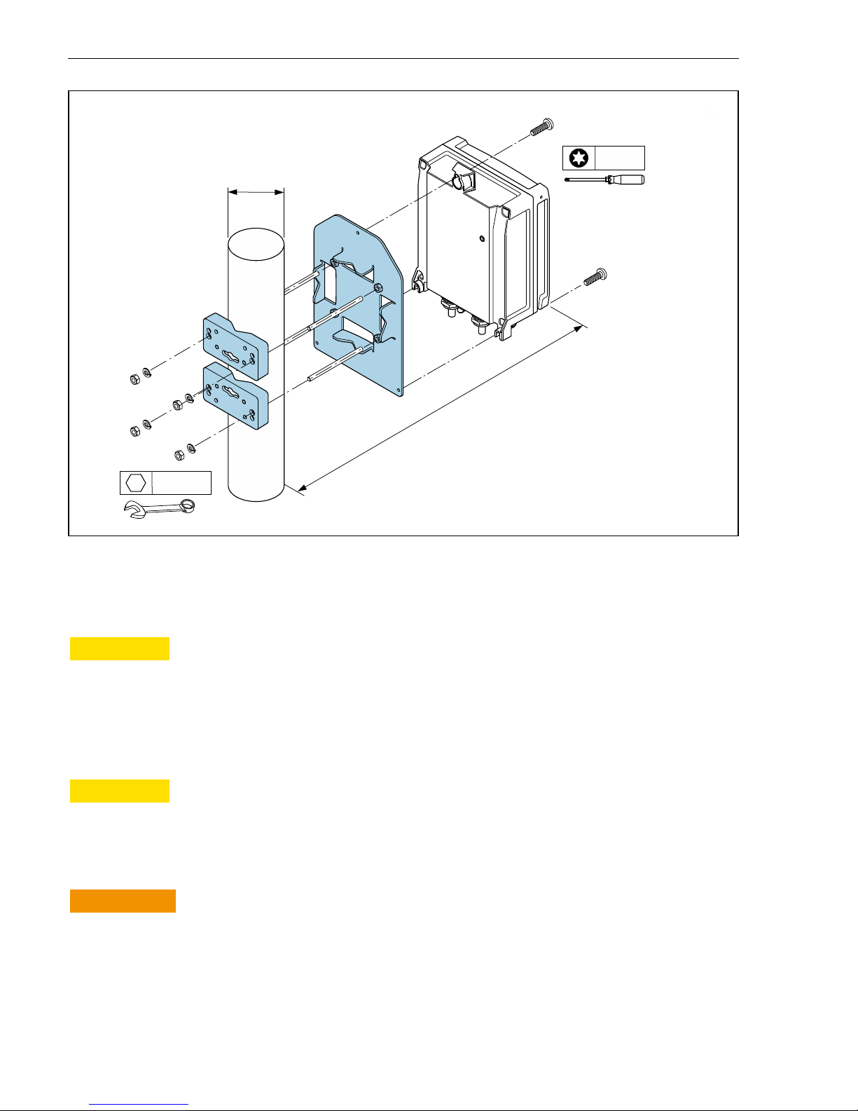
Installation Proline Promag
30 Endress+Hauser
ø 20…70
( 0.79…2.75)ø
~102 (~ 4.0)
4 x
SW 10
3 x
TX 25
A0029051
14 Engineering unit mm (in)
5.2.5 Mounting the transmitter housing: Proline 500
L
CAUTION
Ambient temperature too high!
Danger of electronics overheating and housing deformation.
‣
Do not exceed the permitted maximum ambient temperature .
‣
If operating outdoors: Avoid direct sunlight and exposure to weathering, particularly in
warm climatic regions.
L
CAUTION
Excessive force can damage the housing!
‣
Avoid excessive mechanical stress.
Post mounting
L
WARNING
Order code for "Transmitter housing", option L "Cast, stainless": cast transmitters are
very heavy.
They are unstable if they are not mounted on a secure, fixed post.
‣
Only mount the transmitter on a secure, fixed post on a stable surface.
Page 31
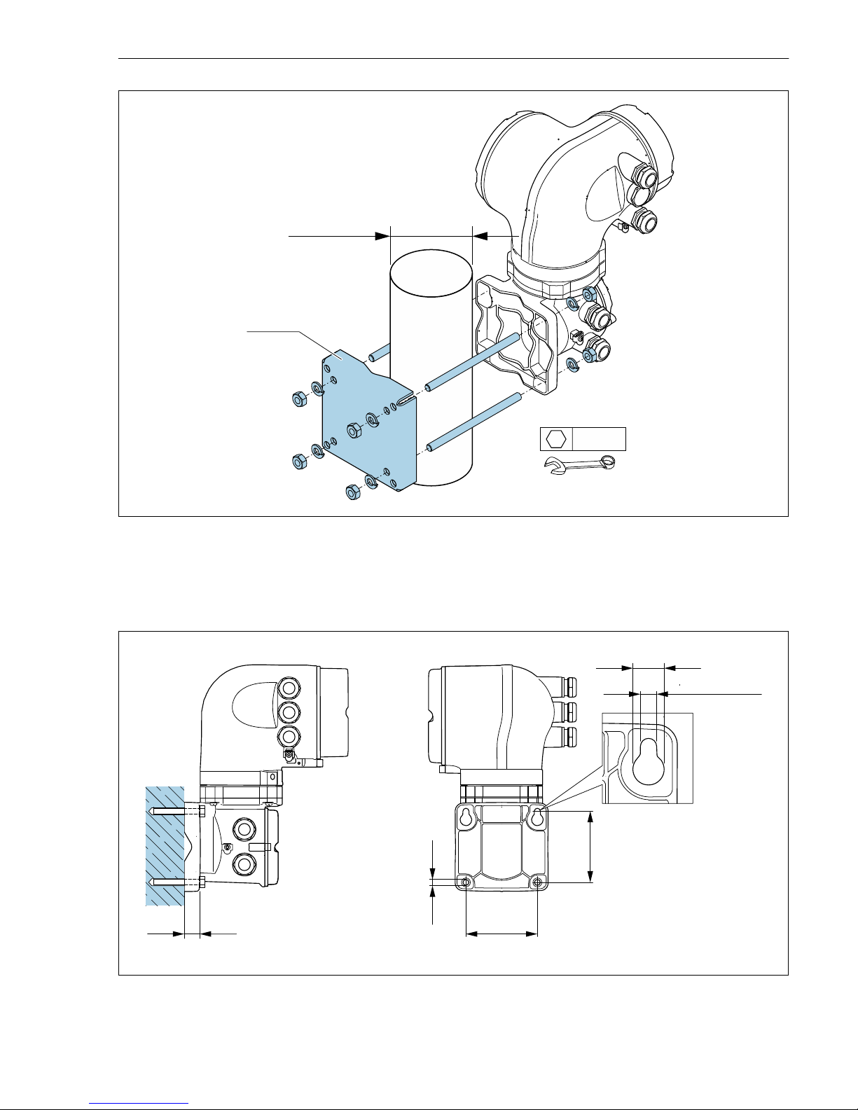
Proline Promag Installation
Endress+Hauser 31
4 x
SW 13
! … (! 0.79 to 2.75)20 70
A0029057
15 Engineering unit mm (in)
Wall mounting
20 (0.79)
100 (3.94)
100 (3.94)
! 8.6 (0.39)
! 18 (0.71)
! 10 (0.39)
A0029068
16 Engineering unit mm (in)
Page 32
Disposal Proline Promag
32 Endress+Hauser
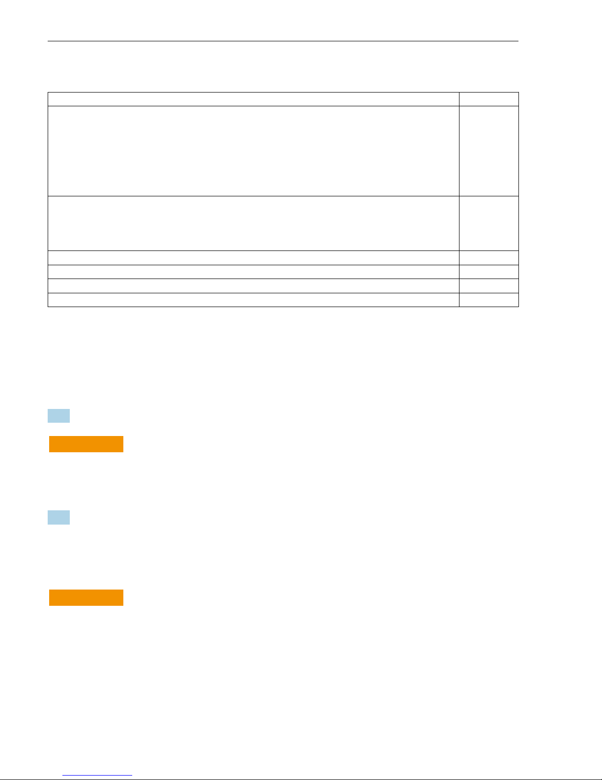
5.3 Post-installation check
Is the device undamaged (visual inspection)?
Does the measuring device conform to the measuring point specifications?
For example:
• Process temperature
• Process pressure (refer to the section on "Pressure-temperature ratings" in the "Technical Information"
document on the CD-ROM provided)
• Ambient temperature
• Measuring range
Has the correct orientation for the sensor been selected ?
• According to sensor type
• According to medium temperature
• According to medium properties (outgassing, with entrained solids)
Does the arrow on the sensor nameplate match the direction of flow of the fluid through the piping ?
Are the measuring point identification and labeling correct (visual inspection)?
Is the device adequately protected from precipitation and direct sunlight?
Have the fixing screws been tightened with the correct tightening torque?
6 Disposal
6.1 Removing the measuring device
1. Switch off the device.
L
WARNING
Danger to persons from process conditions.
‣
Beware of hazardous process conditions such as pressure in the measuring device, high
temperatures or aggressive fluids.
2. Carry out the mounting and connection steps from the "Mounting the measuring device"
and "Connecting the measuring device" sections in reverse order. Observe the safety
instructions.
6.2 Disposing of the measuring device
L
WARNING
Danger to personnel and environment from fluids that are hazardous to health.
‣
Ensure that the measuring device and all cavities are free of fluid residues that are
hazardous to health or the environment, e.g. substances that have permeated into crevices
or diffused through plastic.
Observe the following notes during disposal:
‣
Observe valid federal/national regulations.
‣
Ensure proper separation and reuse of the device components.
Page 33
Proline Promag Appendix
Endress+Hauser 33
7 Appendix
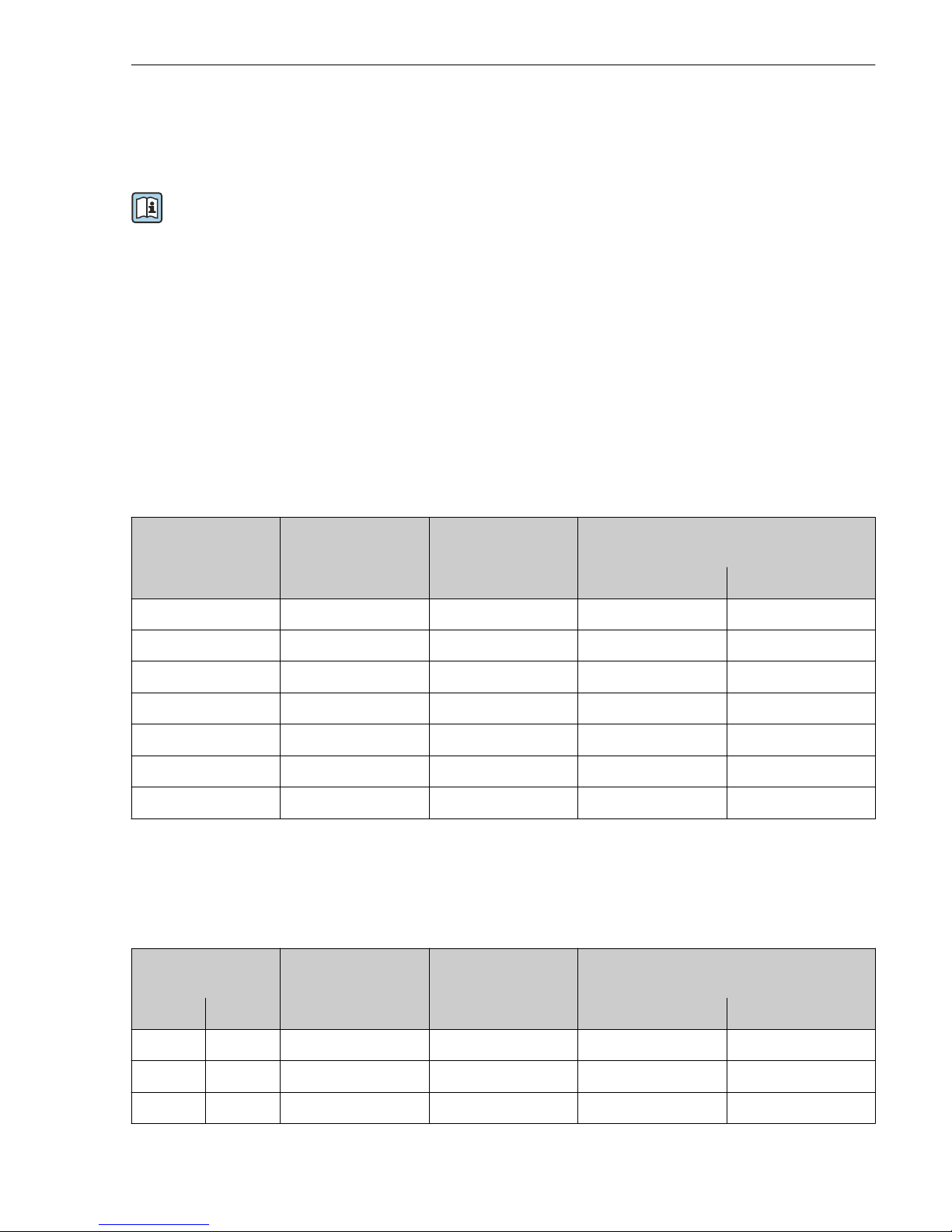
7.1 Screw tightening torques
For detailed information on the screw tightening torques, see the "Mounting the sensor"
section of the Operating Instructions for the device
Please note the following:
• The screw tightening torques listed below apply only to lubricated threads and to pipes not
subjected to tensile stress.
• Tighten the screws uniformly and in diagonally opposite sequence.
• Overtightening the screws will deform the sealing faces or damage the seals.
7.1.1 Promag D
The tightening torques apply to situations where an EPDM soft material flat seal (e.g. 70°
Shore) is used.
Screw tightening torques, mounting bolts and centering sleeves for EN 1092-1 (DIN 2501);
PN 16
Nominal diameter Mounting bolts Length
Centering sleeve
Max. screw tightening torque [Nm] for a
process flange with ...
[mm] [mm] [mm] smooth seal face Raised face
25 4 × M12 × 145 54 19 19
40 4 × M16 × 170 68 33 33
50 4 × M16 × 185 82 41 41
65
1)
4 × M16 × 200 92 44 44
65
2)
8 × M16 × 200 –
3)
29 29
80 8 × M16 × 225 116 36 36
100 8 × M16 × 260 147 40 40
1) EN (DIN) flange: 4-hole → with centering sleeves
2) EN (DIN) flange: 8-hole → without centering sleeves
3) A centering sleeve is not required. The device is centered directly via the sensor housing.
Screw tightening torques, mounting bolts and centering sleeves for ASME B16.5; Class 150
Nominal diameter Mounting bolts Length
Centering sleeve
Max. screw tightening torque [Nm]
([lbf · ft]) for a process flange with ...
[mm] [in] [in] [in] smooth seal face Raised face
25 1 4 × UNC ½" × 5,70 –
1)
19 (14) 10 (7)
40 1 ½ 4 × UNC ½" × 6,50 –
1)
29 (21) 19 (14)
50 2 4 × UNC 5/8" × 7,50 –
1)
41 (30) 37 (27)
Page 34
Appendix Proline Promag
34 Endress+Hauser
Nominal diameter Mounting bolts Length
Centering sleeve
Max. screw tightening torque [Nm]
([lbf · ft]) for a process flange with ...
[mm] [in] [in] [in] smooth seal face Raised face
80 3 4 × UNC 5/8" × 9,25 –
1)
43 (31) 43 (31)
100 4 8 × UNC 5/8" × 10,4 5,79 38 (28) 38 (28)
1) A centering sleeve is not required. The device is centered directly via the sensor housing.
Screw tightening torques, mounting bolts and centering sleeves for JIS B2220; 10K
Nominal diameter Mounting bolts Length
Centering sleeve
Max. screw tightening torque [Nm] for a
process flange with ...
[mm] [mm] [mm] smooth seal face Raised face
25 4 × M16 × 170 54 24 24
40 4 × M16 × 170 68 32 25
50 4 × M16 × 185 –
1)
38 30
65 4 × M16 × 200 –
1)
42 42
80 8 × M16 × 225 –
1)
36 28
100 8 × M16 × 260 –
1)
39 37
1) A centering sleeve is not required. The device is centered directly via the sensor housing.
7.1.2 Promag E, P
Screw tightening torques for EN 1092-1 (DIN 2501); PN 25, 40
Nominal diameter Pressure rating Screws Max. screw tightening torque [Nm]
[mm] [bar] [mm] PTFE PFA
15 PN 40 4 × M12 11 –
25 PN 40 4 × M12 26 20
32 PN 40 4 × M16 41 35
40 PN 40 4 × M16 52 47
50 PN 40 4 × M16 65 59
65
1)
PN 16 8 × M16 43 40
65 PN 40 8 × M16 43 40
80 PN 16 8 × M16 53 48
80 PN 40 8 × M16 53 48
100 PN 16 8 × M16 57 51
100 PN 40 8 × M20 78 70
Page 35

Proline Promag Appendix
Endress+Hauser 35
Nominal diameter Pressure rating Screws Max. screw tightening torque [Nm]
[mm] [bar] [mm] PTFE PFA
125 PN 16 8 × M16 75 67
125 PN 40 8 × M24 111 99
150 PN 16 8 × M20 99 85
150 PN 40 8 × M24 136 120
200 PN 10 8 × M20 141 101
200 PN 16 12 × M20 94 67
200 PN 25 12 × M24 138 105
250 PN 10 12 × M20 110 –
250 PN 16 12 × M24 131 –
250 PN 25 12 × M27 200 –
300 PN 10 12 × M20 125 –
300 PN 16 12 × M24 179 –
300 PN 25 16 × M27 204 –
350 PN 10 16 × M20 188 –
350 PN 16 16 × M24 254 –
350 PN 25 16 × M30 380 –
400 PN 10 16 × M24 260 –
400 PN 16 16 × M27 330 –
400 PN 25 16 × M33 488 –
450 PN 10 20 × M24 235 –
450 PN 16 20 × M27 300 –
450 PN 25 20 × M33 385 –
500 PN 10 20 × M24 265 –
500 PN 16 20 × M30 448 –
500 PN 25 20 × M33 533 –
600 PN 10 20 × M27 345 –
600 PN 16 20 × M33 658 –
600 PN 25 20 × M36 731 –
1) Designed acc. to EN 1092-1 (not to DIN 2501)
Page 36
Appendix Proline Promag
36 Endress+Hauser
Screw tightening torques for ASME B16.5; Class 150, 300
Nominal diameter Pressure rating Screws Max. screw tightening torque [Nm]
([lbf · ft])
[mm] [in] [psi] [in] PTFE PFA
15 ½ Class 150 4 × ½ 6 (4) – (–)
15 ½ Class 300 4 × ½ 6 (4) – (–)
25 1 Class 150 4 × ½ 11 (8) 10 (7)
25 1 Class 300 4 × 5/8 14 (10) 12 (9)
40 1 ½ Class 150 4 × ½ 24 (18) 21 (15)
40 1 ½ Class 300 4 × ¾ 34 (25) 31 (23)
50 2 Class 150 4 × 5/8 47 (35) 44 (32)
50 2 Class 300 8 × 5/8 23 (17) 22 (16)
80 3 Class 150 4 × 5/8 79 (58) 67 (49)
80 3 Class 300 8 × ¾ 47 (35) 42 (31)
100 4 Class 150 8 × 5/8 56 (41) 50 (37)
100 4 Class 300 8 × ¾ 67 (49) 59 (44)
150 6 Class 150 8 × ¾ 106 (78) 86 (63)
150 6 Class 300 12 × ¾ 73 (54) 67 (49)
200 8 Class 150 8 × ¾ 143 (105) 109 (80)
250 10 Class 150 12 × 7/8 135 (100) – (–)
300 12 Class 150 12 × 7/8 178 (131) – (–)
350 14 Class 150 12 × 1 260 (192) – (–)
400 16 Class 150 16 × 1 246 (181) – (–)
450 18 Class 150 16 × 1 1/8 371 (274) – (–)
500 20 Class 150 20 × 1 1/8 341 (252) – (–)
600 24 Class 150 20 × 1 ¼ 477 (352) – (–)
Screw tightening torques for JIS B2220; 10, 20K
Nominal diameter Pressure rating Screws Max. screw tightening torque [Nm]
[mm] [bar] [mm] PTFE PFA
25 10K 4 × M16 32 27
25 20K 4 × M16 32 27
32 10K 4 × M16 38 –
32 20K 4 × M16 38 –
Page 37
Proline Promag Appendix
Endress+Hauser 37
Nominal diameter Pressure rating Screws Max. screw tightening torque [Nm]
[mm] [bar] [mm] PTFE PFA
40 10K 4 × M16 41 37
40 20K 4 × M16 41 37
50 10K 4 × M16 54 46
50 20K 8 × M16 27 23
65 10K 4 × M16 74 63
65 20K 8 × M16 37 31
80 10K 8 × M16 38 32
80 20K 8 × M20 57 46
100 10K 8 × M16 47 38
100 20K 8 × M20 75 58
125 10K 8 × M20 80 66
125 20K 8 × M22 121 103
150 10K 8 × M20 99 81
150 20K 12 × M22 108 72
200 10K 12 × M20 82 54
200 20K 12 × M22 121 88
250 10K 12 × M22 133 –
250 20K 12 × M24 212 –
300 10K 16 × M22 99 –
300 20K 16 × M24 183 –
Screw tightening torques for AS 2129; Table E
Nominal diameter Screws Max. screw tightening torque [Nm]
[mm] [mm] PTFE
25 4 × M12 21
50 4 × M16 42
Screw tightening torques for AS 4087; PN 16
Nominal diameter Screws Max. screw tightening torque [Nm]
[mm] [mm] PTFE
50 4 × M16 42
Page 38

Appendix Proline Promag
38 Endress+Hauser
7.1.3 Promag L
Screw tightening torques for EN 1092-1 (DIN 2501); PN 6, 10, 16
Nominal
diameter
Pressure rating Screws Max. screw tightening torque [Nm]
[mm] [bar] [mm] Hard rubber Polyurethane PTFE
25 PN 10/16 4 × M12 – 6 11
32 PN 10/16 4 × M16 – 16 27
40 PN 10/16 4 × M16 – 16 29
50 PN 10/16 4 × M16 – 15 40
65
1)
PN 10/16 8 × M16 – 10 22
80 PN 10/16 8 × M16 – 15 30
100 PN 10/16 8 × M16 – 20 42
125 PN 10/16 8 × M16 – 30 55
150 PN 10/16 8 × M20 – 50 90
200 PN 16 12 × M20 – 65 87
250 PN 16 12 × M24 – 126 151
300 PN 16 12 × M24 – 139 177
350 PN 6 12 × M20 111 120 –
350 PN 10 16 × M20 112 118 –
350 PN 16 16 × M24 152 165 –
400 PN 6 16 × M20 90 98 –
400 PN 10 16 × M24 151 167 –
400 PN 16 16 × M27 193 215 –
450 PN 6 16 × M20 112 126 –
450 PN 10 20 × M24 153 133 –
500 PN 6 20 × M20 119 123 –
500 PN 10 20 × M24 155 171 –
500 PN 16 20 × M30 275 300 –
600 PN 6 20 × M24 139 147 –
600 PN 10 20 × M27 206 219 –
600 PN 16 20 × M33 415 443 –
700 PN 6 24 × M24 148 139 –
700 PN 10 24 × M27 246 246 –
700 PN 16 24 × M33 278 318 –
Page 39

Proline Promag Appendix
Endress+Hauser 39
Nominal
diameter
Pressure rating Screws Max. screw tightening torque [Nm]
[mm] [bar] [mm] Hard rubber Polyurethane PTFE
800 PN 6 24 × M27 206 182 –
800 PN 10 24 × M30 331 316 –
800 PN 16 24 × M36 369 385 –
900 PN 6 24 × M27 230 637 –
900 PN 10 28 × M30 316 307 –
900 PN 16 28 × M36 353 398 –
1 000 PN 6 28 × M27 218 208 –
1 000 PN 10 28 × M33 402 405 –
1 000 PN 16 28 × M39 502 518 –
1 200 PN 6 32 × M30 319 299 –
1 200 PN 10 32 × M36 564 568 –
1 200 PN 16 32 × M45 701 753 –
1 400 PN 6 36 × M33 430 – –
1 400 PN 10 36 × M39 654 – –
1 400 PN 16 36 × M45 729 – –
1 600 PN 6 40 × M33 440 – –
1 600 PN 10 40 × M45 946 – –
1 600 PN 16 40 × M52 1 007 – –
1 800 PN 6 44 × M36 547 – –
1 800 PN 10 44 × M45 961 – –
1 800 PN 16 44 × M52 1 108 – –
2 000 PN 6 48 × M39 629 – –
2 000 PN 10 48 × M45 1 047 – –
2 000 PN 16 48 × M56 1 324 – –
2 200 PN 6 52 × M39 698 – –
2 200 PN 10 52 × M52 1 217 – –
2 400 PN 6 56 × M39 768 – –
2 400 PN 10 56 × M52 1 229 – –
1) Designed acc. to EN 1092-1 (not to DIN 2501)
Page 40
Appendix Proline Promag
40 Endress+Hauser
Screw tightening torques for ASME B16.5; Class 150
Nominal diameter Screws Max. screw tightening torque [Nm] ([lbf · ft])
[mm] [in] [in] Hard rubber Polyurethane PTFE
25 1 4 × 5/8 – 5 (4) 14 (13)
40 1 ½ 8 × 5/8 – 10 (7) 21 (15)
50 2 4 × 5/8 – 15 (11) 40 (29)
80 3 4 × 5/8 – 25 (18) 65 (48)
100 4 8 × 5/8 – 20 (15) 44 (32)
150 6 8 × ¾ – 45 (33) 90 (66)
200 8 8 × ¾ – 65 (48) 87 (64)
250 10 12 × 7/8 – 126 (93) 151 (112)
300 12 12 × 7/8 – 146 (108) 177 (131)
350 14 12 × 1 135 (100) 158 (117) –
400 16 16 × 1 128 (94) 150 (111) –
450 18 16 × 1 1/8 204 (150) 234 (173) –
500 20 20 × 1 1/8 183 (135) 217 (160) –
600 24 20 × 1 ¼ 268 (198) 307 (226) –
Screw tightening torques for AWWA C207; Class D
Nominal diameter Screws Max. screw tightening torque [Nm] ([lbf · ft])
[mm] [in] [in] Hard rubber Polyurethane PTFE
700 28 28 × 1 ¼ 247 (182) 292 (215) –
750 30 28 × 1 ¼ 287 (212) 302 (223) –
800 32 28 × 1 ½ 394 (291) 422 (311) –
900 36 32 × 1 ½ 419 (309) 430 (317) –
1 000 40 36 × 1 ½ 420 (310) 477 (352) –
1 050 42 36 × 1 ½ 528 (389) 518 (382) –
1 200 48 44 × 1 ½ 552 (407) 531 (392) –
1 350 54 44 × 1 ¾ 730 (538) – –
1 500 60 52 × 1 ¾ 758 (559) – –
1 650 66 52 × 1 ¾ 946 (698) – –
1 800 72 60 × 1 ¾ 975 (719) – –
2 000 78 64 × 2 853 (629) – –
Page 41
Proline Promag Appendix
Endress+Hauser 41
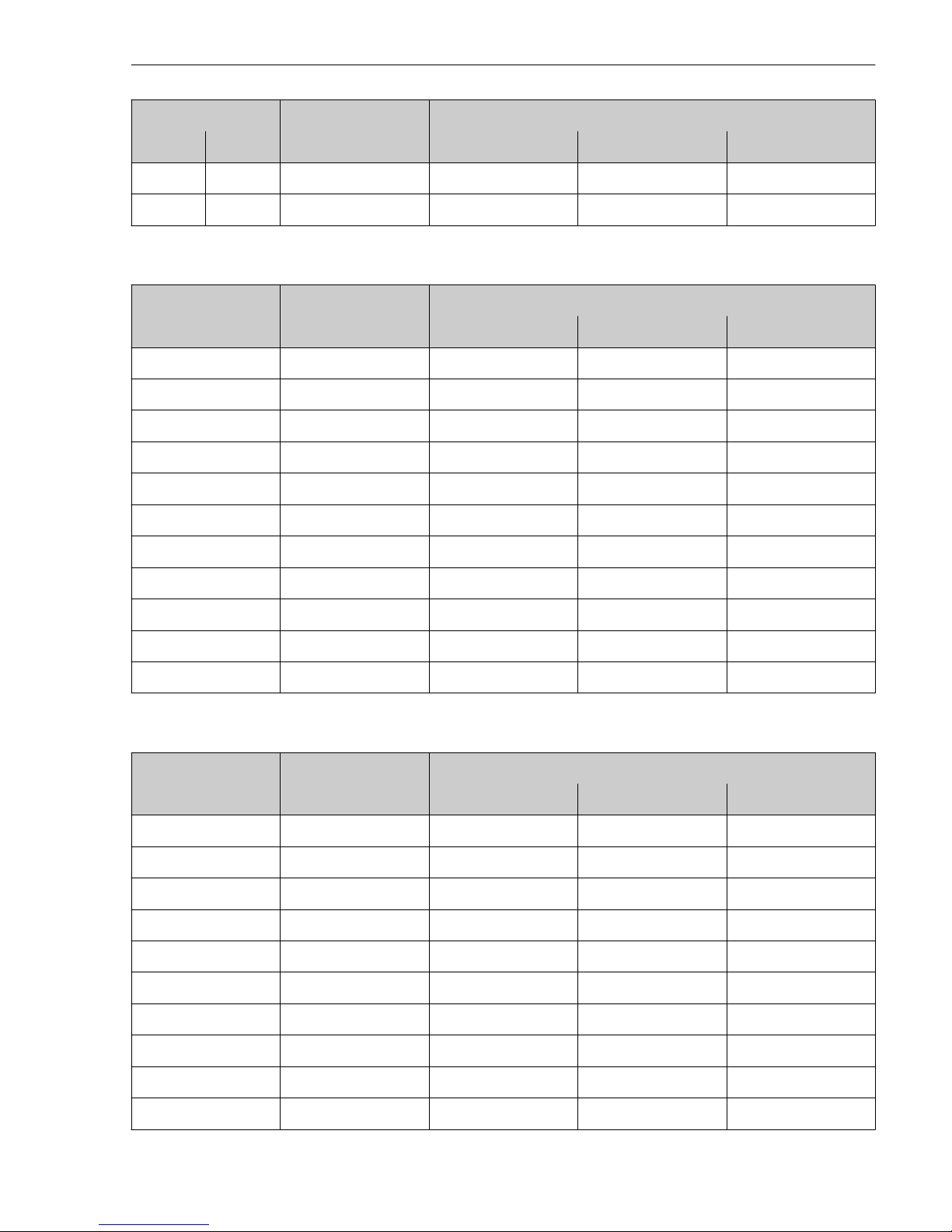
Nominal diameter Screws Max. screw tightening torque [Nm] ([lbf · ft])
[mm] [in] [in] Hard rubber Polyurethane PTFE
2 150 84 64 × 2 931 (687) – –
2 300 90 68 × 2 ¼ 1 048 (773) – –
Screw tightening torques for AS 2129; Table E
Nominal diameter Screws Max. screw tightening torque [Nm]
[mm] [mm] Hard rubber Polyurethane PTFE
350 12 × M24 203 – –
400 12 × M24 226 – –
450 16 × M24 226 – –
500 16 × M24 271 – –
600 16 × M30 439 – –
700 20 × M30 355 – –
750 20 × M30 559 – –
800 20 × M30 631 – –
900 24 × M30 627 – –
1 000 24 × M30 634 – –
1 200 32 × M30 727 – –
Screw tightening torques for AS 4087; PN 16
Nominal diameter Screws Max. screw tightening torque [Nm]
[mm] [mm] Hard rubber Polyurethane PTFE
350 12 × M24 203 – –
375 12 × M24 137 – –
400 12 × M24 226 – –
450 12 × M24 301 – –
500 16 × M24 271 – –
600 16 × M27 393 – –
700 20 × M27 330 – –
750 20 × M30 529 – –
800 20 × M33 631 – –
900 24 × M33 627 – –
Page 42

Appendix Proline Promag
42 Endress+Hauser
Nominal diameter Screws Max. screw tightening torque [Nm]
[mm] [mm] Hard rubber Polyurethane PTFE
1 000 24 × M33 595 – –
1 200 32 × M33 703 – –
7.1.4 Promag W
Screw tightening torques for EN 1092-1 (DIN 2501); PN 6, 10, 16, 25, 40
Nominal diameter Pressure rating Screws Max. screw tightening torque [Nm]
[mm] [bar] [mm] Hard rubber Polyurethane
25 PN 40 4 × M12 – 15
32 PN 40 4 × M16 – 24
40 PN 40 4 × M16 – 31
50 PN 40 4 × M16 48 40
65
1)
PN 16 8 × M16 32 27
65 PN 40 8 × M16 32 27
80 PN 16 8 × M16 40 34
80 PN 40 8 × M16 40 34
100 PN 16 8 × M16 43 36
100 PN 40 8 × M20 59 50
125 PN 16 8 × M16 56 48
125 PN 40 8 × M24 83 71
150 PN 16 8 × M20 74 63
150 PN 40 8 × M24 104 88
200 PN 10 8 × M20 106 91
200 PN 16 12 × M20 70 61
200 PN 25 12 × M24 104 92
250 PN 10 12 × M20 82 71
250 PN 16 12 × M24 98 85
250 PN 25 12 × M27 150 134
300 PN 10 12 × M20 94 81
300 PN 16 12 × M24 134 118
300 PN 25 16 × M27 153 138
350 PN 6 12 × M20 111 120
Page 43

Proline Promag Appendix
Endress+Hauser 43
Nominal diameter Pressure rating Screws Max. screw tightening torque [Nm]
[mm] [bar] [mm] Hard rubber Polyurethane
350 PN 10 16 × M20 112 118
350 PN 16 16 × M24 152 165
350 PN 25 16 × M30 227 252
400 PN 6 16 × M20 90 98
400 PN 10 16 × M24 151 167
400 PN 16 16 × M27 193 215
400 PN 25 16 × M33 289 326
450 PN 6 16 × M20 112 126
450 PN 10 20 × M24 153 133
450 PN 16 20 × M27 198 196
450 PN 25 20 × M33 256 253
500 PN 6 20 × M20 119 123
500 PN 10 20 × M24 155 171
500 PN 16 20 × M30 275 300
500 PN 25 20 × M33 317 360
600 PN 6 20 × M24 139 147
600 PN 10 20 × M27 206 219
600 PN 16 20 × M33 415 443
600 PN 25 20 × M36 431 516
700 PN 6 24 × M24 148 139
700 PN 10 24 × M27 246 246
700 PN 16 24 × M33 278 318
700 PN 25 24 × M39 449 507
800 PN 6 24 × M27 206 182
800 PN 10 24 × M30 331 316
800 PN 16 24 × M36 369 385
800 PN 25 24 × M45 664 721
900 PN 6 24 × M27 230 637
900 PN 10 28 × M30 316 307
900 PN 16 28 × M36 353 398
900 PN 25 28 × M45 690 716
1 000 PN 6 28 × M27 218 208
Page 44
Appendix Proline Promag
44 Endress+Hauser
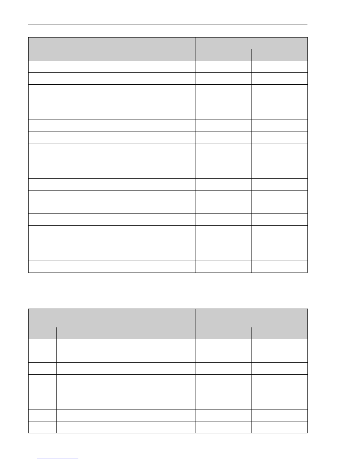
Nominal diameter Pressure rating Screws Max. screw tightening torque [Nm]
[mm] [bar] [mm] Hard rubber Polyurethane
1 000 PN 10 28 × M33 402 405
1 000 PN 16 28 × M39 502 518
1 000 PN 25 28 × M52 970 971
1 200 PN 6 32 × M30 319 299
1 200 PN 10 32 × M36 564 568
1 200 PN 16 32 × M45 701 753
1 400 PN 6 36 × M33 430 398
1 400 PN 10 36 × M39 654 618
1 400 PN 16 36 × M45 729 762
1 600 PN 6 40 × M33 440 417
1 600 PN 10 40 × M45 946 893
1 600 PN 16 40 × M52 1 007 1 100
1 800 PN 6 44 × M36 547 521
1 800 PN 10 44 × M45 961 895
1 800 PN 16 44 × M52 1 108 1 003
2 000 PN 6 48 × M39 629 605
2 000 PN 10 48 × M45 1 047 1 092
2 000 PN 16 48 × M56 1 324 1 261
1) Designed acc. to EN 1092-1 (not to DIN 2501)
Screw tightening torques for ASME B16.5; Class 150, 300
Nominal diameter Pressure rating Screws Max. screw tightening torque [Nm]
([lbf · ft])
[mm] [in] [psi] [in] Hard rubber Polyurethane
25 1 Class 150 4 × ½ – 7 (5)
25 1 Class 300 4 × 5/8 – 8 (6)
40 1 ½ Class 150 4 × ½ – 10 (7)
40 1 ½ Class 300 4 × ¾ – 15 (11)
50 2 Class 150 4 × 5/8 35 (26) 22 (16)
50 2 Class 300 8 × 5/8 18 (13) 11 (8)
80 3 Class 150 4 × 5/8 60 (44) 43 (32)
80 3 Class 300 8 × ¾ 38 (28) 26 (19)
Page 45
Proline Promag Appendix
Endress+Hauser 45
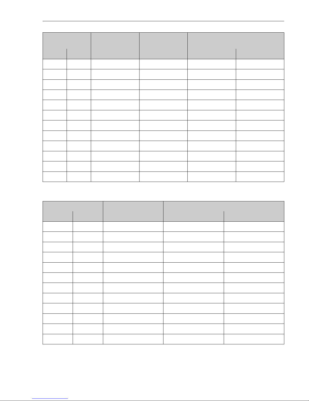
Nominal diameter Pressure rating Screws Max. screw tightening torque [Nm]
([lbf · ft])
[mm] [in] [psi] [in] Hard rubber Polyurethane
100 4 Class 150 8 × 5/8 42 (31) 31 (23)
100 4 Class 300 8 × ¾ 58 (43) 40 (30)
150 6 Class 150 8 × ¾ 79 (58) 59 (44)
150 6 Class 300 12 × ¾ 70 (52) 51 (38)
200 8 Class 150 8 × ¾ 107 (79) 80 (59)
250 10 Class 150 12 × 7/8 101 (74) 75 (55)
300 12 Class 150 12 × 7/8 133 (98) 103 (76)
350 14 Class 150 12 × 1 135 (100) 158 (117)
400 16 Class 150 16 × 1 128 (94) 150 (111)
450 18 Class 150 16 × 1 1/8 204 (150) 234 (173)
500 20 Class 150 20 × 1 1/8 183 (135) 217 (160)
600 24 Class 150 20 × 1 ¼ 268 (198) 307 (226)
Screw tightening torques for AWWA C207; Class D
Nominal diameter Screws Max. screw tightening torque [Nm] ([lbf · ft])
[mm] [in] [in] Hard rubber Polyurethane
700 28 28 × 1 ¼ 247 (182) 292 (215)
750 30 28 × 1 ¼ 287 (212) 302 (223)
800 32 28 × 1 ½ 394 (291) 422 (311)
900 36 32 × 1 ½ 419 (309) 430 (317)
1 000 40 36 × 1 ½ 420 (310) 477 (352)
1 050 42 36 × 1 ½ 528 (389) 518 (382)
1 200 48 44 × 1 ½ 552 (407) 531 (392)
1 350 54 44 × 1 ¾ 730 (538) –
1 500 60 52 × 1 ¾ 758 (559) –
1 650 66 52 × 1 ¾ 946 (698) –
1 800 72 60 × 1 ¾ 975 (719) –
2 000 78 64 × 2 853 (629) –
Page 46
Appendix Proline Promag
46 Endress+Hauser
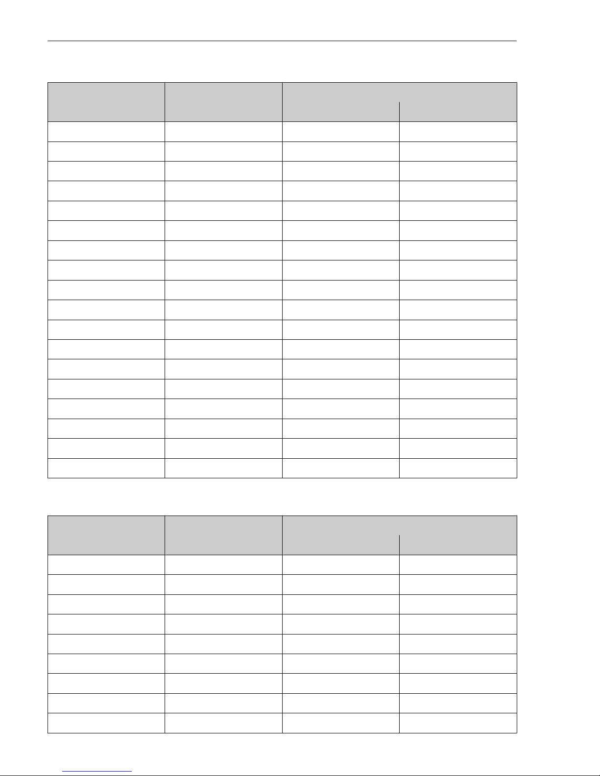
Screw tightening torques for AS 2129; Table E
Nominal diameter Screws Max. screw tightening torque [Nm]
[mm] [mm] Hard rubber Polyurethane
50 4 × M16 32 –
80 4 × M16 49 –
100 8 × M16 38 –
150 8 × M20 64 –
200 8 × M20 96 –
250 12 × M20 98 –
300 12 × M24 123 –
350 12 × M24 203 –
400 12 × M24 226 –
450 16 × M24 226 –
500 16 × M24 271 –
600 16 × M30 439 –
700 20 × M30 355 –
750 20 × M30 559 –
800 20 × M30 631 –
900 24 × M30 627 –
1 000 24 × M30 634 –
1 200 32 × M30 727 –
Screw tightening torques for AS 4087; PN 16
Nominal diameter Screws Max. screw tightening torque [Nm]
[mm] [mm] Hard rubber Polyurethane
50 4 × M16 32 –
80 4 × M16 49 –
100 4 × M16 76 –
150 8 × M20 52 –
200 8 × M20 77 –
250 8 × M20 147 –
300 12 × M24 103 –
350 12 × M24 203 –
375 12 × M24 137 –
Page 47
Proline Promag Appendix
Endress+Hauser 47
Nominal diameter Screws Max. screw tightening torque [Nm]
[mm] [mm] Hard rubber Polyurethane
400 12 × M24 226 –
450 12 × M24 301 –
500 16 × M24 271 –
600 16 × M27 393 –
700 20 × M27 330 –
750 20 × M30 529 –
800 20 × M33 631 –
900 24 × M33 627 –
1 000 24 × M33 595 –
1 200 32 × M33 703 –
Screw tightening torques for JIS B2220; 10, 20K
Nominal diameter Pressure rating Screws Max. screw tightening torque [Nm]
[mm] [bar] [mm] Hard rubber Polyurethane
25 10K 4 × M16 – 19
25 20K 4 × M16 – 19
32 10K 4 × M16 – 22
32 20K 4 × M16 – 22
40 10K 4 × M16 – 24
40 20K 4 × M16 – 24
50 10K 4 × M16 40 33
50 20K 8 × M16 20 17
65 10K 4 × M16 55 45
65 20K 8 × M16 28 23
80 10K 8 × M16 29 23
80 20K 8 × M20 42 35
100 10K 8 × M16 35 29
100 20K 8 × M20 56 48
125 10K 8 × M20 60 51
125 20K 8 × M22 91 79
150 10K 8 × M20 75 63
150 20K 12 × M22 81 72
Page 48
Appendix Proline Promag
48 Endress+Hauser
Nominal diameter Pressure rating Screws Max. screw tightening torque [Nm]
[mm] [bar] [mm] Hard rubber Polyurethane
200 10K 12 × M20 61 52
200 20K 12 × M22 91 80
250 10K 12 × M22 100 87
250 20K 12 × M24 159 144
300 10K 16 × M22 74 63
300 20K 16 × M24 138 124
Page 49

Page 50

Page 51

Page 52

www.addresses.endress.com
 Loading...