

Page 1
Products Solutions Services
Brief Operating Instructions
Proline 200
HART
Transmitter with
Vortex flow sensor
These instructions are Brief Operating Instructions; they are
not a substitute for the Operating Instructions pertaining to
the device.
Transmitter Brief Operating Instructions
Contain information about the transmitter.
Sensor Brief Operating Instructions → 3
KA01326D/06/EN/01.18
71384790
Page 2
Proline 200 HART
2 Endress+Hauser
Order code:
Ext. ord. cd.:
Ser. no.:
www.endress.com/deviceviewer
Endress+Hauser
Operations App
XXXXXXXXXXXX
XXXXX-XXXXXX
XXX.XXXX.XX
Serial number
1.
3.
2.
A0023555
Page 3

Proline 200 HART Brief Operating Instructions for the device
Endress+Hauser 3
Brief Operating Instructions for the device
The device consists of a transmitter and a sensor.
The process of commissioning these two components is described in two separate manuals:
• Sensor Brief Operating Instructions
• Transmitter Brief Operating Instructions
Please refer to both Brief Operating Instructions when commissioning the device as the
contents of the manuals complement one another:
Sensor Brief Operating Instructions
The Sensor Brief Operating Instructions are aimed at specialists with responsibility for
installing the measuring device.
• Incoming acceptance and product identification
• Storage and transport
• Installation
Transmitter Brief Operating Instructions
The Transmitter Brief Operating Instructions are aimed at specialists with responsibility for
commissioning, configuring and parameterizing the measuring device (until the first
measured value).
• Product description
• Installation
• Electrical connection
• Operation options
• System integration
• Commissioning
• Diagnostic information
Additional device documentation
These Brief Operating Instructions are the Transmitter Brief Operating Instructions.
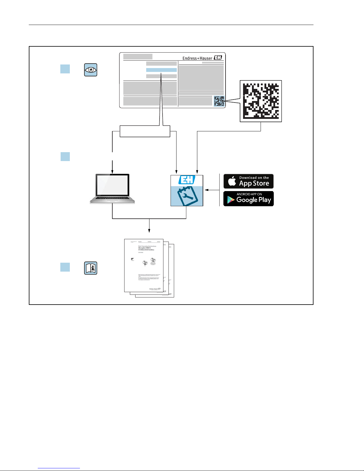
The "Sensor Brief Operating Instructions" are available via:
• Internet: www.endress.com/deviceviewer
• Smart phone/tablet: Endress+Hauser Operations App
Detailed information about the device can be found in the Operating Instructions and the
other documentation:
• Internet: www.endress.com/deviceviewer
• Smart phone/tablet: Endress+Hauser Operations App
Page 4

Table of contents Proline 200 HART
4 Endress+Hauser
Table of contents
1 Document information ............................................................ 5
1.1 Symbols used ......................................................................... 5
2 Basic safety instructions .......................................................... 7
2.1 Requirements for the personnel ............................................................7
2.2 Designated use ........................................................................ 7
2.3 Workplace safety ...................................................................... 8
2.4 Operational safety ......................................................................8
2.5 Product safety .........................................................................8
2.6 IT security ............................................................................8
2.7 Device-specific IT security ................................................................ 9
3 Product description ............................................................... 9
4 Installation ....................................................................... 9
4.1 Mounting the pressure measuring unit ...................................................... 9
4.2 Mounting the transmitter of the remote version ................................................ 9
4.3 Turning the transmitter housing .......................................................... 11
4.4 Turning the display module .............................................................. 11
4.5 Transmitter post-installation check ........................................................ 12
5 Electrical connection ............................................................ 13
5.1 Connection conditions .................................................................. 13
5.2 Connecting the measuring device ......................................................... 21
5.3 Ensuring the degree of protection ......................................................... 28
5.4 Post-connection check ..................................................................29
6 Operation options ............................................................... 30
6.1 Overview of operation options ............................................................ 30
6.2 Structure and function of the operating menu ................................................ 31
6.3 Access to the operating menu via the local display ............................................. 32
6.4 Access to the operating menu via the operating tool ............................................ 35
7 System integration .............................................................. 35
8 Commissioning .................................................................. 35
8.1 Function check ....................................................................... 35
8.2 Switching on the measuring device ........................................................ 36
8.3 Setting the operating language ........................................................... 36
8.4 Configuring the measuring device ......................................................... 36
8.5 Defining the tag name ..................................................................37
8.6 Protecting settings from unauthorized access ................................................. 38
8.7 Application-specific commissioning ........................................................ 38
9 Diagnostic information .......................................................... 44
Page 5
Proline 200 HART Document information
Endress+Hauser 5
1 Document information
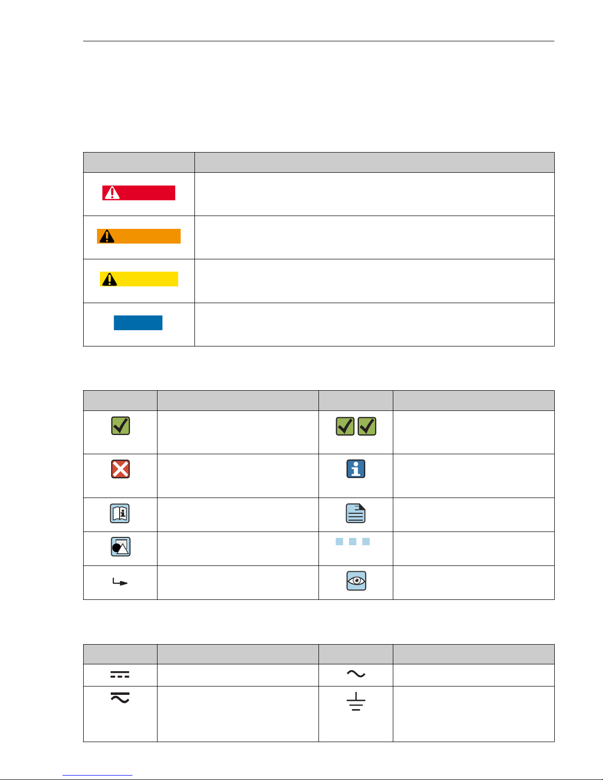
1.1 Symbols used
1.1.1 Safety symbols
Symbol Meaning
DANGER
DANGER!
This symbol alerts you to a dangerous situation. Failure to avoid this situation will result in
serious or fatal injury.
WARNING
WARNING!
This symbol alerts you to a dangerous situation. Failure to avoid this situation can result in
serious or fatal injury.
CAUTION
CAUTION!
This symbol alerts you to a dangerous situation. Failure to avoid this situation can result in
minor or medium injury.
NOTICE
NOTE!
This symbol contains information on procedures and other facts which do not result in
personal injury.
1.1.2 Symbols for certain types of information
Symbol Meaning Symbol Meaning
Permitted
Procedures, processes or actions that
are permitted.
Preferred
Procedures, processes or actions that
are preferred.
Forbidden
Procedures, processes or actions that
are forbidden.
Tip
Indicates additional information.
Reference to documentation
A
Reference to page
Reference to graphic
1.
, 2., 3.… Series of steps
Result of a step Visual inspection
1.1.3 Electrical symbols
Symbol Meaning Symbol Meaning
Direct current Alternating current
Direct current and alternating current Ground connection
A grounded terminal which, as far as
the operator is concerned, is grounded
via a grounding system.
Page 6
Document information Proline 200 HART
6 Endress+Hauser
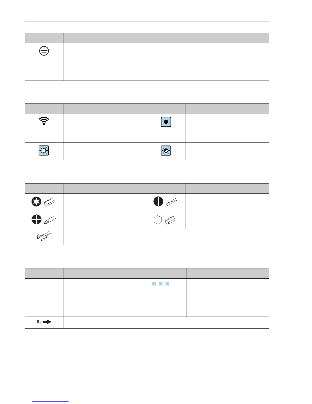
Symbol Meaning
Protective Earth (PE)
A terminal which must be connected to ground prior to establishing any other connections.
The ground terminals are situated inside and outside the device:
• Inner ground terminal: Connects the protectiv earth to the mains supply.
• Outer ground terminal: Connects the device to the plant grounding system.
1.1.4 Communication symbols
Symbol Meaning Symbol Meaning
Wireless Local Area Network
(WLAN)
Communication via a wireless, local
network.
LED
Light emitting diode is off.
LED
Light emitting diode is on.
LED
Light emitting diode is flashing.
1.1.5 Tool symbols
Symbol Meaning Symbol Meaning
Torx screwdriver Flat blade screwdriver
Cross-head screwdriver Allen key
Open-ended wrench
1.1.6 Symbols in graphics
Symbol Meaning Symbol Meaning
1, 2, 3,... Item numbers
1.
, 2., 3.… Series of steps
A, B, C, ... Views A-A, B-B, C-C, ... Sections
-
Hazardous area
.
Safe area (non-hazardous area)
Flow direction
Page 7

Proline 200 HART Basic safety instructions
Endress+Hauser 7
2 Basic safety instructions
2.1 Requirements for the personnel
The personnel must fulfill the following requirements for its tasks:
‣
Trained, qualified specialists must have a relevant qualification for this specific function
and task.
‣
Are authorized by the plant owner/operator.
‣
Are familiar with federal/national regulations.
‣
Before starting work, read and understand the instructions in the manual and
supplementary documentation as well as the certificates (depending on the application).
‣
Follow instructions and comply with basic conditions.
2.2 Designated use
Application and media
Depending on the version ordered, the measuring device can also measure potentially
explosive, flammable, poisonous and oxidizing media.
Measuring devices for use in hazardous areas, in hygienic applications or where there is an
increased risk due to process pressure, are labeled accordingly on the nameplate.
To ensure that the measuring device remains in proper condition for the operation time:
‣
Keep within the specified pressure and temperature range.
‣
Only use the measuring device in full compliance with the data on the nameplate and the
general conditions listed in the Operating Instructions and supplementary documentation.
‣
Based on the nameplate, check whether the ordered device is permitted for the intended
use in the hazardous area (e.g. explosion protection, pressure vessel safety).
‣
Use the measuring device only for media to which the process-wetted materials are
sufficiently resistant.
‣
If the measuring device is not operated at atmospheric temperature, compliance with the
relevant basic conditions specified in the associated device documentation is absolutely
essential: "Documentation" section.
‣
Protect the measuring device permanently against corrosion from environmental
influences.
Incorrect use
Non-designated use can compromise safety. The manufacturer is not liable for damage caused
by improper or non-designated use.
L
WARNING
Danger of breakage due to corrosive or abrasive fluids!
‣
Verify the compatibility of the process fluid with the sensor material.
‣
Ensure the resistance of all fluid-wetted materials in the process.
‣
Keep within the specified pressure and temperature range.
Page 8

Basic safety instructions Proline 200 HART
8 Endress+Hauser
NOTICE
Verification for borderline cases:
‣
For special fluids and fluids for cleaning, Endress+Hauser is glad to provide assistance in
verifying the corrosion resistance of fluid-wetted materials, but does not accept any
warranty or liability as minute changes in the temperature, concentration or level of
contamination in the process can alter the corrosion resistance properties.
Residual risks
L
WARNING
The electronics and the medium may cause the surfaces to heat up. This presents a burn
hazard!
‣
For elevated fluid temperatures, ensure protection against contact to prevent burns.
2.3 Workplace safety
For work on and with the device:
‣
Wear the required personal protective equipment according to federal/national
regulations.
For welding work on the piping:
‣
Do not ground the welding unit via the measuring device.
If working on and with the device with wet hands:
‣
Due to the increased risk of electric shock, gloves must be worn.
2.4 Operational safety
Risk of injury.
‣
Operate the device in proper technical condition and fail-safe condition only.
‣
The operator is responsible for interference-free operation of the device.
2.5 Product safety
This measuring device is designed in accordance with good engineering practice to meet stateof-the-art safety requirements, has been tested, and left the factory in a condition in which it
is safe to operate.
It meets general safety standards and legal requirements. It also complies with the EU
directives listed in the device-specific EU Declaration of Conformity. Endress+Hauser confirms
this by affixing the CE mark to the device.
2.6 IT security
We only provide a warranty if the device is installed and used as described in the Operating
Instructions. The device is equipped with security mechanisms to protect it against any
inadvertent changes to the device settings.
IT security measures in line with operators' security standards and designed to provide
additional protection for the device and device data transfer must be implemented by the
operators themselves.
Page 9

Proline 200 HART Product description
Endress+Hauser 9
2.7 Device-specific IT security
The device offers a range of specific functions to support protective measures on the operator's
side. These functions can be configured by the user and guarantee greater in-operation safety
if used correctly.
For detailed information on device-specific IT security, see the Operating Instructions for
the device.
3 Product description
The device consists of a transmitter and a sensor.
Two device versions are available:
• Compact version – transmitter and sensor form a mechanical unit.
• Remote version - transmitter and sensor are mounted in separate locations.
For detailed information on the product description, see the Operating Instructions for
the device
4 Installation
For detailed information about mounting the sensor, see the Sensor Brief Operating
Instructions → 3
4.1 Mounting the pressure measuring unit
For detailed information on mounting the pressure measuring unit, see the Brief
Operating Instructions for the sensor.→ 3
4.2 Mounting the transmitter of the remote version
L
CAUTION
Ambient temperature too high!
Danger of electronics overheating and housing deformation.
‣
Do not exceed the permitted maximum ambient temperature .
‣
If operating outdoors: Avoid direct sunlight and exposure to weathering, particularly in
warm climatic regions.
L
CAUTION
Excessive force can damage the housing!
‣
Avoid excessive mechanical stress.
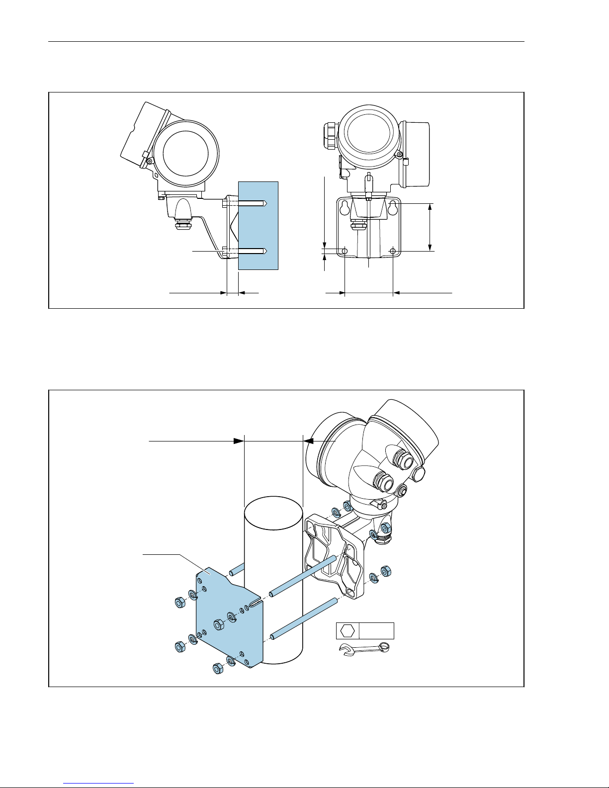
The transmitter of the remote version can be mounted in the following ways:
• Wall mounting
• Pipe mounting
Page 10
Installation Proline 200 HART
10 Endress+Hauser
4.2.1 Wall mounting
80 (3.15)
80 (3.15)
19 (0.6)
! 8.6 (0.39)
M8
A0033484
1 mm (in)
4.2.2 Post mounting
! …20 70
(! 0.79 to 2.75)
4 x
SW 13
A0033486
2 mm (in)
Page 11
Proline 200 HART Installation
Endress+Hauser 11
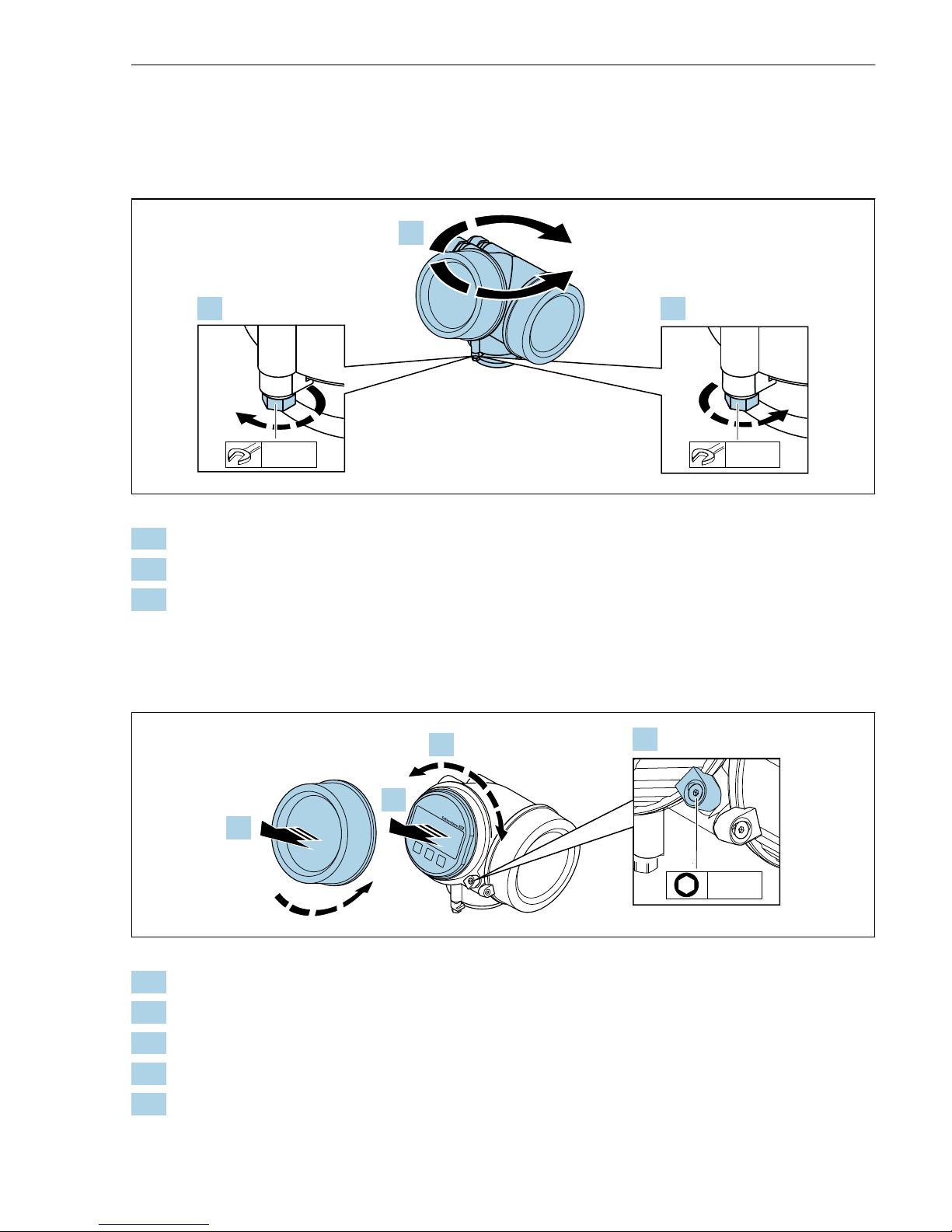
4.3 Turning the transmitter housing
To provide easier access to the connection compartment or display module, the transmitter
housing can be turned.
max. 350°
8 mm
8 mm
1.
2.
3.
A0032242
1. Release the fixing screw.
2. Turn the housing to the desired position.
3. Firmly tighten the securing screw.
4.4 Turning the display module
The display module can be turned to optimize display readability and operability.
+
E
–
1
3 mm
1.
2.
3.
4.
A0032238
1. Loosen the securing clamp of the electronics compartment cover using an Allen key.
2. Unscrew cover of the electronics compartment from the transmitter housing.
3. Optional: pull out the display module with a gentle rotational movement.
4. Turn the display module to the desired position: max. 8 × 45° in every direction.
5. Without display module pulled out:
Allow display module to engage at desired position.
Page 12

Installation Proline 200 HART
12 Endress+Hauser
6. With display module pulled out:
Feed the cable into the gap between the housing and main electronics module and plug
the display module into the electronics compartment until it engages.
7. Reverse the removal procedure to reassemble the transmitter.
4.5 Transmitter post-installation check
The post-installation check must always be performed after the following tasks:
• Turning the transmitter housing
• Turning the display module
Is the device undamaged (visual inspection)?
Are the securing screw and securing clamp tightened securely?
Page 13

Proline 200 HART Electrical connection
Endress+Hauser 13
5 Electrical connection
5.1 Connection conditions
5.1.1 Required tools
• For cable entries: Use corresponding tools
• For securing clamp: Allen key 3 mm
• Wire stripper
• When using stranded cables: Crimper for wire end ferrule
• For removing cables from terminal: Flat blade screwdriver ≤ 3 mm (0.12 in)
5.1.2 Connecting cable requirements
The connecting cables provided by the customer must fulfill the following requirements.
Electrical safety
In accordance with applicable federal/national regulations.
Permitted temperature range
• The installation guidelines that apply in the country of installation must be observed.
• The cables must be suitable for the minimum and maximum temperatures to be expected.
Signal cable
Current output 4 to 20 mA HART
A shielded cable is recommended. Observe grounding concept of the plant.
Current output 4 to 20 mA
Standard installation cable is sufficient.
Pulse/frequency/switch output
Standard installation cable is sufficient.
Current input
Standard installation cable is sufficient.
Cable diameter
• Cable glands supplied:
M20 × 1.5 with cable 6 to 12 mm (0.24 to 0.47 in)
• Plug-in spring terminals for device version without integrated overvoltage protection: wire
cross-sections 0.5 to 2.5 mm2 (20 to 14 AWG)
• Screw terminals for device version with integrated overvoltage protection: wire crosssections 0.2 to 2.5 mm2 (24 to 14 AWG)
Page 14
Electrical connection Proline 200 HART
14 Endress+Hauser
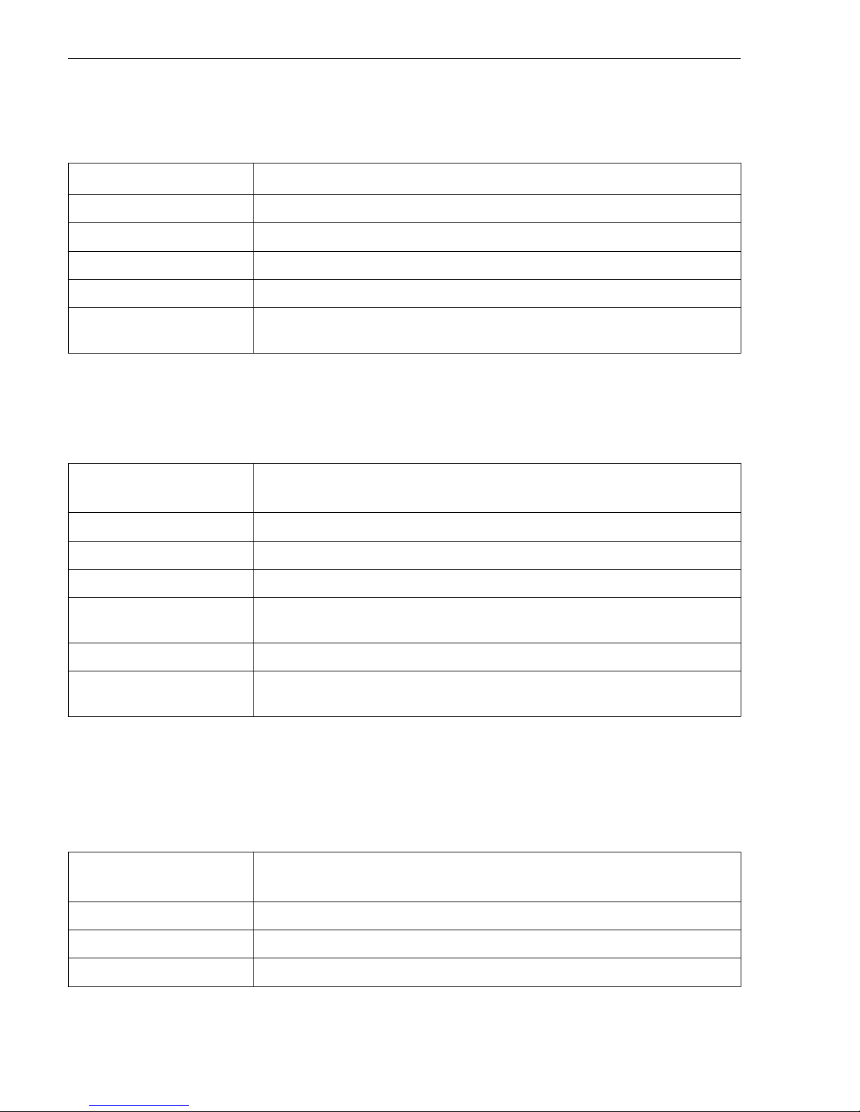
5.1.3 Connecting cable for remote version
Connecting cable (standard)
Standard cable
2 × 2 × 0.5 mm2 (22 AWG) PVC cable with common shield (2 pairs, pair-stranded)
1)
Flame resistance According to DIN EN 60332-1-2
Oil-resistance According to DIN EN 60811-2-1
Shielding Galvanized copper-braid, opt. density approx.85 %
Cable length 5 m (16 ft), 10 m (32 ft), 20 m (65 ft), 30 m (98 ft)
Operating temperature When mounted in a fixed position: –50 to +105 °C (–58 to +221 °F); when cable can
move freely: –25 to +105 °C (–13 to +221 °F)
1) UV radiation may cause damage to the outer jacket of the cable. Protect the cable from exposure to sun as much
as possible.
Connecting cable (reinforced)
Cable, reinforced
2 × 2 × 0.34 mm2 (22 AWG) PVC cable with common shield (2 pairs, pair-stranded)
and additional steel-wire braided sheath
1)
Flame resistance According to DIN EN 60332-1-2
Oil-resistance According to DIN EN 60811-2-1
Shielding Galvanized copper-braid, opt. density approx. 85%
Strain relief and
reinforcement
Steel-wire braid, galvanized
Cable length 5 m (16 ft), 10 m (32 ft), 20 m (65 ft), 30 m (98 ft)
Operating temperature When mounted in a fixed position: –50 to +105 °C (–58 to +221 °F); when cable can
move freely: –25 to +105 °C (–13 to +221 °F)
1) UV radiation may cause damage to the outer jacket of the cable. Protect the cable from exposure to sun as much
as possible.
Connecting cable (option "mass pressure-/temperature-compensated")
Order code for "Sensor version; DSC sensor; measuring tube", option DA, DB, DC, DD
Standard cable
[(3 × 2) + 1] × 0.34 mm2 (22 AWG)PVC cable with common shield (3 pairs, pairstranded)
1)
Flame resistance According to DIN EN 60332-1-2
Oil-resistance According to DIN EN 60811-2-1
Shielding Galvanized copper-braid, opt. density approx. 85%
Page 15

Proline 200 HART Electrical connection
Endress+Hauser 15
Cable length 10 m (32 ft), 30 m (98 ft)
Operating temperature When mounted in a fixed position: –50 to +105 °C (–58 to +221 °F); when cable can
move freely: –25 to +105 °C (–13 to +221 °F)
1) UV radiation may cause damage to the outer jacket of the cable. Protect the cable from exposure to sun as much
as possible.
Page 16
Electrical connection Proline 200 HART
16 Endress+Hauser
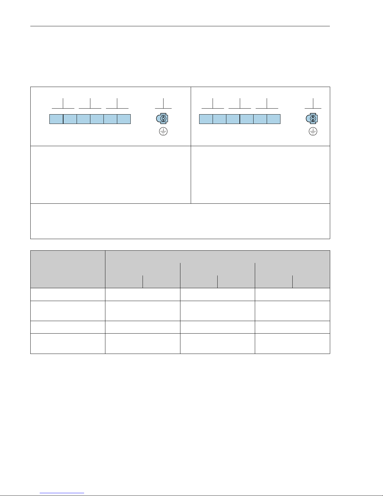
5.1.4 Terminal assignment
Transmitter
4-20 mA HART connection version with additional inputs and outputs
3 4 1 2
4
5 6
+ – + –+ –
123
A0033475
3 4 1 2
4
5 6
+ – + –+ –
123
A0033475
Maximum number of terminals
Terminals 1 to 6:
Without integrated overvoltage protection
Maximum number of terminals for order code for
"Accessory mounted", option NA "Overvoltage
protection"
• Terminals 1 to 4:
With integrated overvoltage protection
• Terminals 5 to 6:
Without integrated overvoltage protection
1
2
3
4
Output 1 (passive): supply voltage and signal transmission
Output 2 (passive): supply voltage and signal transmission
Input (passive): supply voltage and signal transmission
Ground terminal for cable shield
Order code for "Output" Terminal numbers
Output 1 Output 2 Input
1 (+) 2 (-) 3 (+) 4 (-) 5 (+) 6 (-)
Option A 4-20 mA HART (passive) - -
Option B
1)
4-20 mA HART (passive)
Pulse/frequency/switch
output (passive)
-
Option C
1)
4-20 mA HART (passive) 4-20 mA analog (passive) -
Option D
1) 2)
4-20 mA HART (passive)
Pulse/frequency/switch
output (passive)
4-20 mA current input
(passive)
1) Output 1 must always be used; output 2 is optional.
2) The integrated overvoltage protection is not used with option D: Terminals 5 and 6 (current input) are not
protected against overvoltage.
Page 17
Proline 200 HART Electrical connection
Endress+Hauser 17
Connecting cable for remote version
Transmitter and sensor connection housing
In the case of the remote version, the sensor and transmitter are mounted separately from on
another and connected by a connecting cable. Connection is performed via the sensor
connection housing and the transmitter housing.
How the connecting cable is connected in the transmitter housing depends on the
measuring device approval and the version of the connecting cable used.
In the following versions, only terminals can be used for connection in the transmitter
housing:
• Certain approvals: Ex nA, Ex ec, Ex tb and Division 1
• Use of reinforced connecting cable
• Order code for "Sensor version; DSC sensor; measuring tube", option DA, DB, DC, DD
In the following versions, an M12 device connector is used for connection in the
transmitter housing:
• All other approvals
• Use of connecting cable (standard)
Terminals are always used to connect the connecting cable in the sensor connection
housing (tightening torques for screws for cable strain relief: 1.2 to 1.7 Nm).
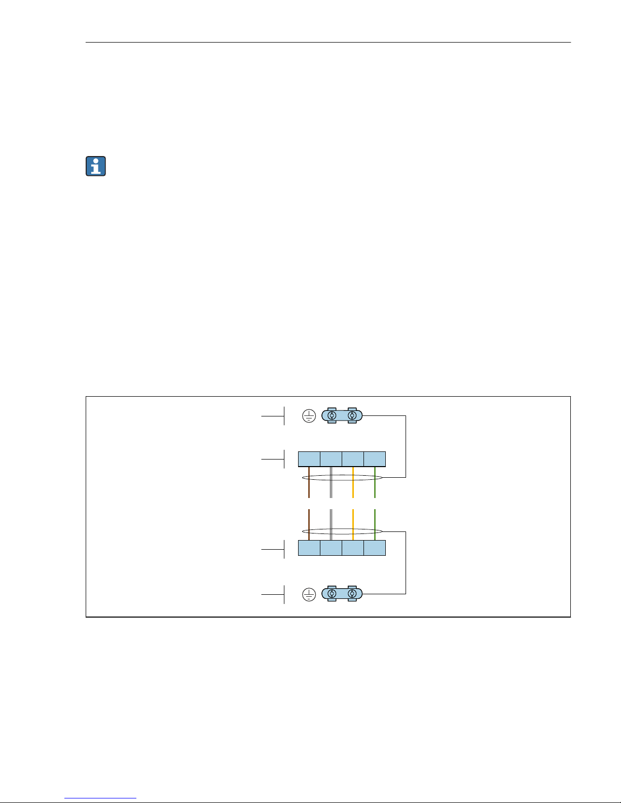
Connecting cable (standard, reinforced)
+ –
+ –
2
1
1
2
1 2 3 4
1 2 3 4
GNYEWHBN
A0033476
3 Terminals for connection compartment in the transmitter wall holder and the sensor connection
housing
1 Terminals for connecting cable
2 Grounding via the cable strain relief
Page 18
Electrical connection Proline 200 HART
18 Endress+Hauser
Terminal number Assignment Cable color
Connecting cable
1 Supply voltage Brown
2 Grounding White
3 RS485 (+) Yellow
4 RS485 (–) Green
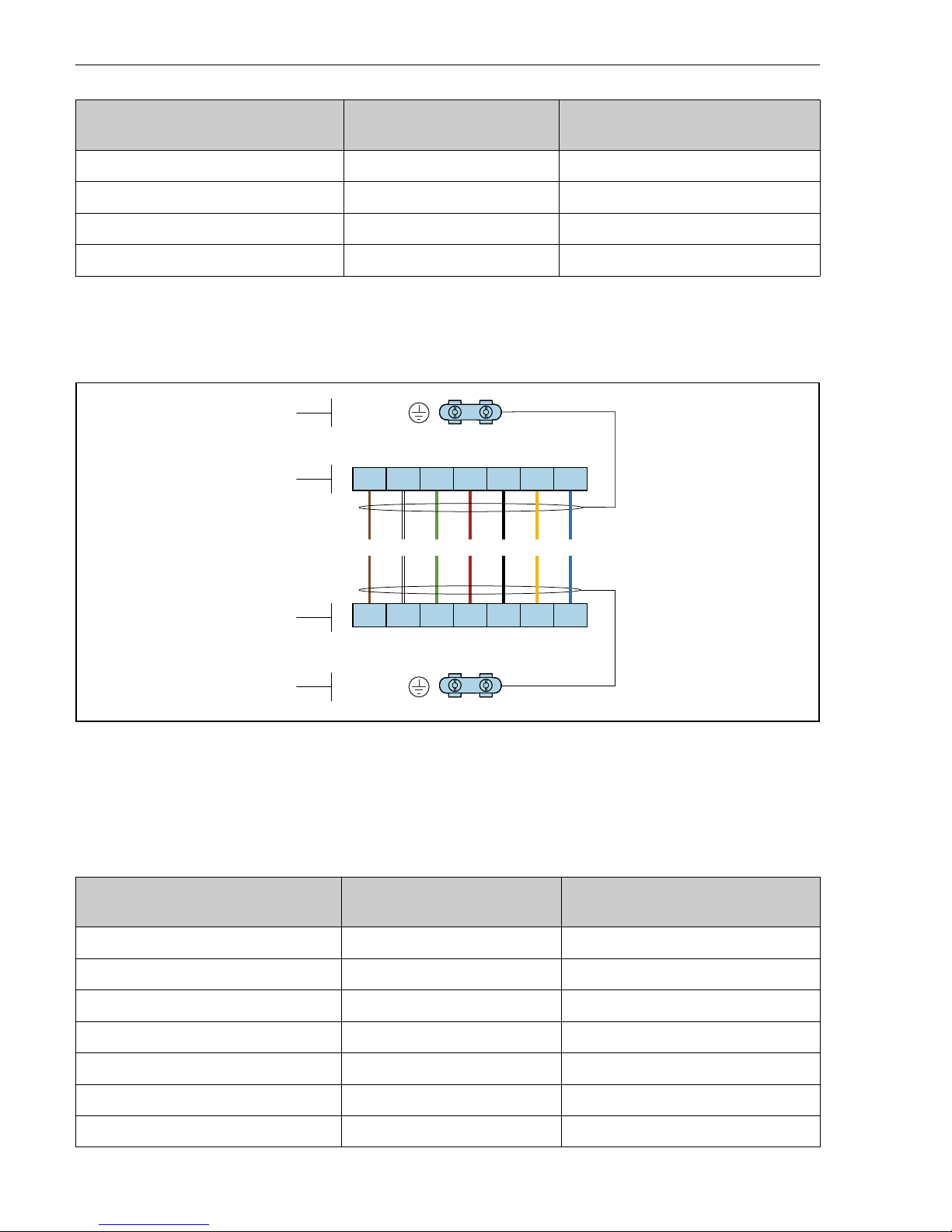
Connecting cable (option "mass pressure-/temperature-compensated")
Order code for "Sensor version; DSC sensor; measuring tube", option DA, DB, DC, DD
+–
+ –
2
1
1
2
1 2 3 4
1 2 3 4556677
RDGNWHBN BK YE BU
+–
+ –
RES
VCC
GND
RES
VCC
GND
A0034571
4 Terminals for connection compartment in the transmitter wall holder and the sensor connection
housing
1 Terminals for connecting cable
2 Grounding via the cable strain relief
Terminal number Assignment Cable color
Connecting cable
1 RS485 (-) DPC Brown
2 RS485 (+) DPC White
3 Reset Green
4 Supply voltage red
5 Grounding Black
6 RS485 (+) Yellow
7 RS485 (–) Blue
Page 19
Proline 200 HART Electrical connection
Endress+Hauser 19
5.1.5 Requirements for the supply unit
Supply voltage
Transmitter
An external power supply is required for each output.
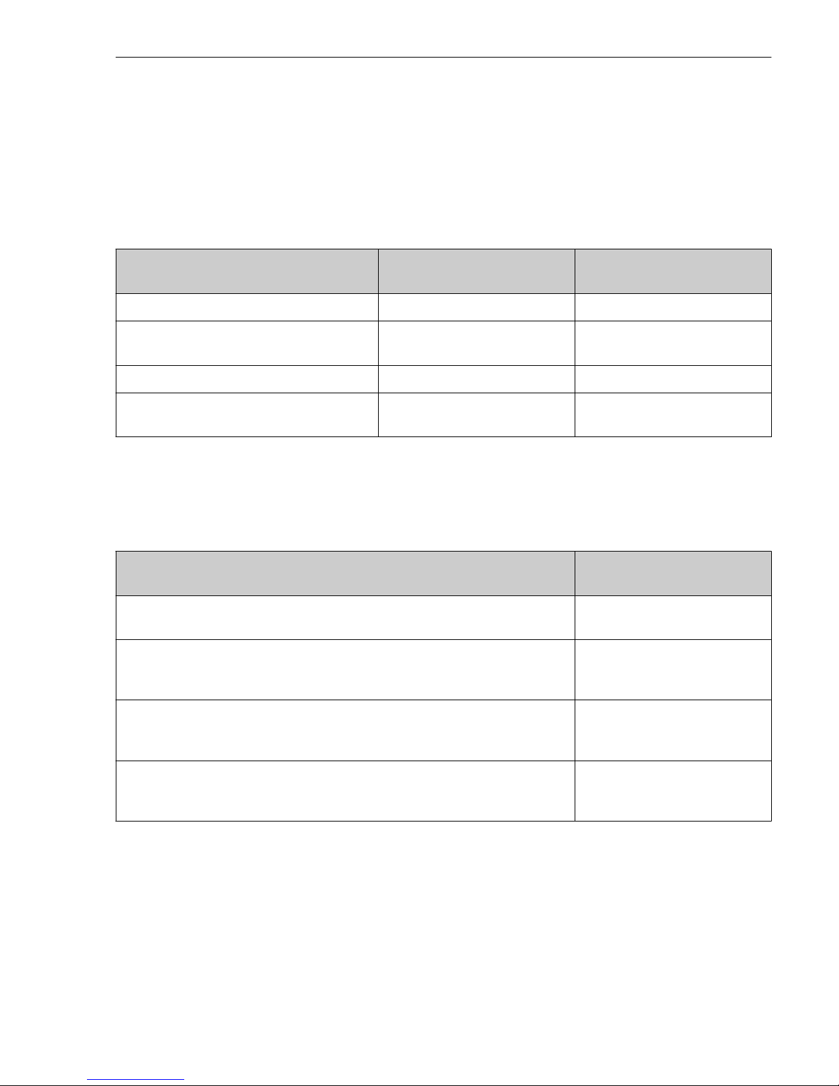
Supply voltage for a compact version without a local display
1)
Order code for "Output" Minimum
terminal voltage
2)
Maximum
terminal voltage
Option A: 4-20 mA HART ≥ DC 12 V DC 35 V
Option B: 4-20 mA HART, pulse/frequency/
switch output
≥ DC 12 V DC 35 V
Option C: 4-20 mA HART + 4-20 mA analog ≥ DC 12 V DC 30 V
Option D: 4-20 mA HART, pulse/frequency/
switch output, 4-20 mA current input
3)
≥ DC 12 V DC 35 V
1) In event of external supply voltage of the power supply unit with load
2) The minimum terminal voltage increases if local operation is used: see the following table
3) Voltage drop 2.2 to 3 V for 3.59 to 22 mA
Increase in minimum terminal voltage
Local operation
Increase in minimum
terminal voltage
Order code for "Display; Operation", option C:
Local operation SD02
+ DC 1 V
Order code for "Display; Operation", option E:
Local operation SD03 with lighting
(backlighting not used)
+ DC 1 V
Order code for "Display; Operation", option E:
Local operation SD03 with lighting
(backlighting used)
+ DC 3 V
Order code for "Sensor version; DSC sensor; measuring tube", option DA, DB, DC,
DD:
Mass (pressure-/temperature-compensated)
+ DC 1 V
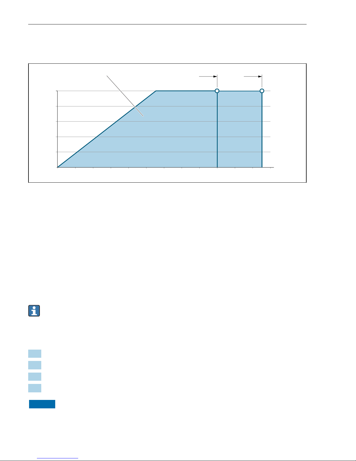
Load
Load for current output: 0 to 500 Ω, depending on the external supply voltage of the power
supply unit
Calculation of the maximum load
Depending on the supply voltage of the power supply unit (US), the maximum load (RB)
including line resistance must be observed to ensure adequate terminal voltage at the device.
In doing so, observe the minimum terminal voltage
Page 20
Electrical connection Proline 200 HART
20 Endress+Hauser
• RB ≤ (US - U
term. min
): 0.022 A
• RB ≤ 500 Ω
0
100
200
300
400
500
12 14 16
18 20
22 24 26 28
U [V]
s
R [W]
b
1.1 1.21
30 32 34 36
A0033472
5 Load for a compact version without local operation
1 Operating range
1.1 For order code for "Output", option A "4-20 mA HART"/option B "4-20 mA HART, pulse/frequency/
switch output" with Ex i and option C "4-20 mA HART + 4-20 mA analog"
1.2 For order code for "Output", option A "4-20 mA HART"/option B "4-20 mA HART, pulse/frequency/
switch output" for non-hazardous area and Ex d
Sample calculation
Supply voltage of power supply unit:
– US = 19 V
– U
term. min
= 12 V (measuring device) + 1 V (local operation without lighting) = 13 V
Maximum load: RB ≤ (19 V - 13 V): 0.022 A = 273 Ω
The minimum terminal voltage (U
Kl min
) increases if local operation is used.→ 19.
5.1.6 Preparing the measuring device
Carry out the steps in the following order:
1. Mount the sensor and transmitter.
2. Connection housing, sensor: Connect connecting cable.
3. Transmitter: Connect connecting cable.
4. Transmitter: Connect signal cable and cable for supply voltage.
NOTICE
Insufficient sealing of the housing!
Operational reliability of the measuring device could be compromised.
‣
Use suitable cable glands corresponding to the degree of protection.
Page 21
Proline 200 HART Electrical connection
Endress+Hauser 21
1. Remove dummy plug if present.
2. If the measuring device is supplied without cable glands:
Provide suitable cable gland for corresponding connecting cable.
3. If the measuring device is supplied with cable glands:
Observe requirements for connecting cables → 13.
5.2 Connecting the measuring device
NOTICE
Limitation of electrical safety due to incorrect connection!
‣
Have electrical connection work carried out by appropriately trained specialists only.
‣
Observe applicable federal/national installation codes and regulations.
‣
Comply with local workplace safety regulations.
‣
Always connect the protective ground cable before connecting additional cables.
‣
For use in potentially explosive atmospheres, observe the information in the device-specific
Ex documentation.
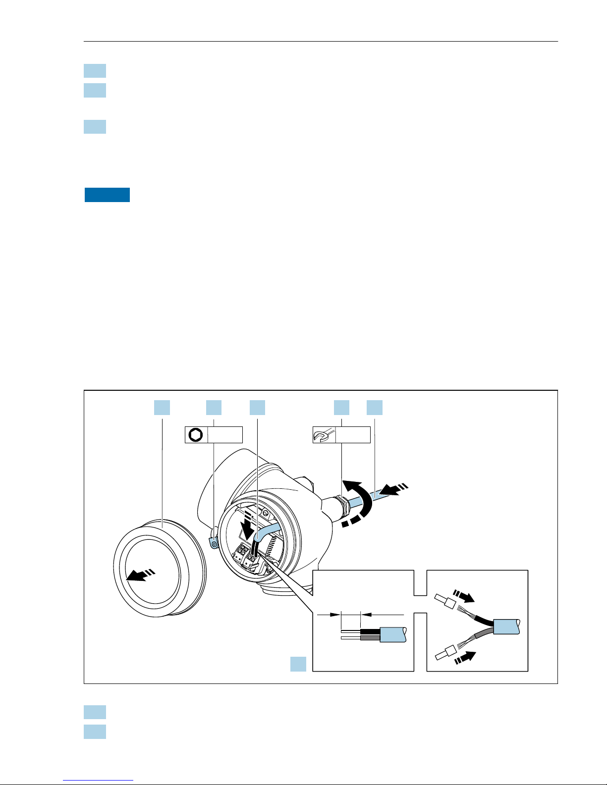
5.2.1 Connecting the compact version
Connecting the transmitter
Connection via terminals
10 (0.4)
mm (in)
20 mm3 mm
1.2. 3.
4.
5. 6.
A0032239
1. Loosen the securing clamp of the connection compartment cover.
2. Unscrew the connection compartment cover.
Page 22
Electrical connection Proline 200 HART
22 Endress+Hauser
3. Push the cable through the cable entry . To ensure tight sealing, do not remove the
sealing ring from the cable entry.
4. Strip the cable and cable ends. In the case of stranded cables, also fit ferrules.
5. Connect cable in accordance with terminal assignment→ 16.. For HART
communication: when connecting the cable shielding to the ground clamp, observe the
grounding concept of the facility.
6.
L
WARNING
Housing degree of protection may be voided due to insufficient sealing of the
housing.
‣
Screw in the screw without using any lubricant. The threads on the cover are coated
with a dry lubricant.
Firmly tighten the cable glands.
7. Reverse the removal procedure to reassemble the transmitter.
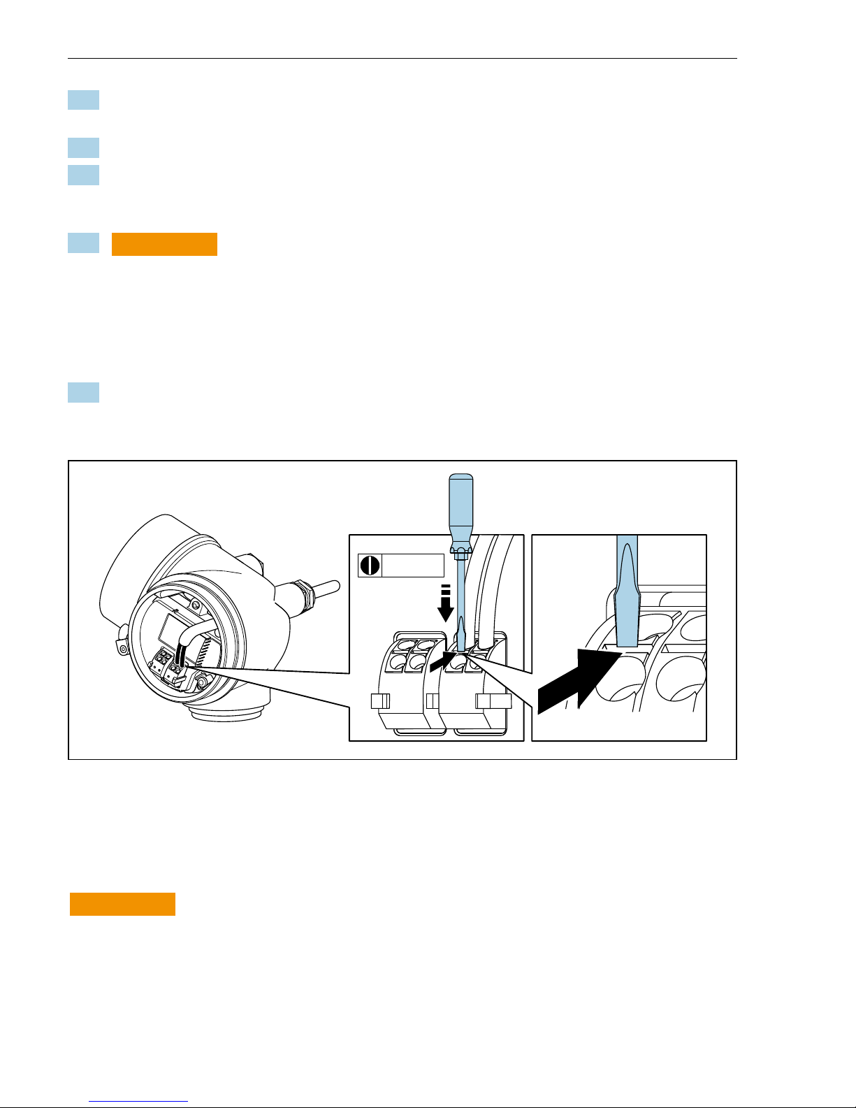
Removing a cable
213 4
3 (0.12)
A0032240
‣
To remove a cable from the terminal, use a flat-blade screwdriver to push the slot between
the two terminal holes while simultaneously pulling the cable end out of the terminal.
5.2.2 Connecting the remote version
L
WARNING
Risk of damaging the electronic components!
‣
Connect the sensor and transmitter to the same potential equalization.
‣
Only connect the sensor to a transmitter with the same serial number.
Page 23
Proline 200 HART Electrical connection
Endress+Hauser 23
The following procedure (in the action sequence given) is recommended for the remote
version:
1. Mount the sensor and transmitter.
2. Connect the connecting cable for the remote version.
3. Connect the transmitter.
How the connecting cable is connected in the transmitter housing depends on the
measuring device approval and the version of the connecting cable used.
In the following versions, only terminals can be used for connection in the transmitter
housing:
• Certain approvals: Ex nA, Ex ec, Ex tb and Division 1
• Use of reinforced connecting cable
• Order code for "Sensor version; DSC sensor; measuring tube", option DA, DB, DC, DD
In the following versions, an M12 device connector is used for connection in the
transmitter housing:
• All other approvals
• Use of connecting cable (standard)
Terminals are always used to connect the connecting cable in the sensor connection
housing (tightening torques for screws for cable strain relief: 1.2 to 1.7 Nm).
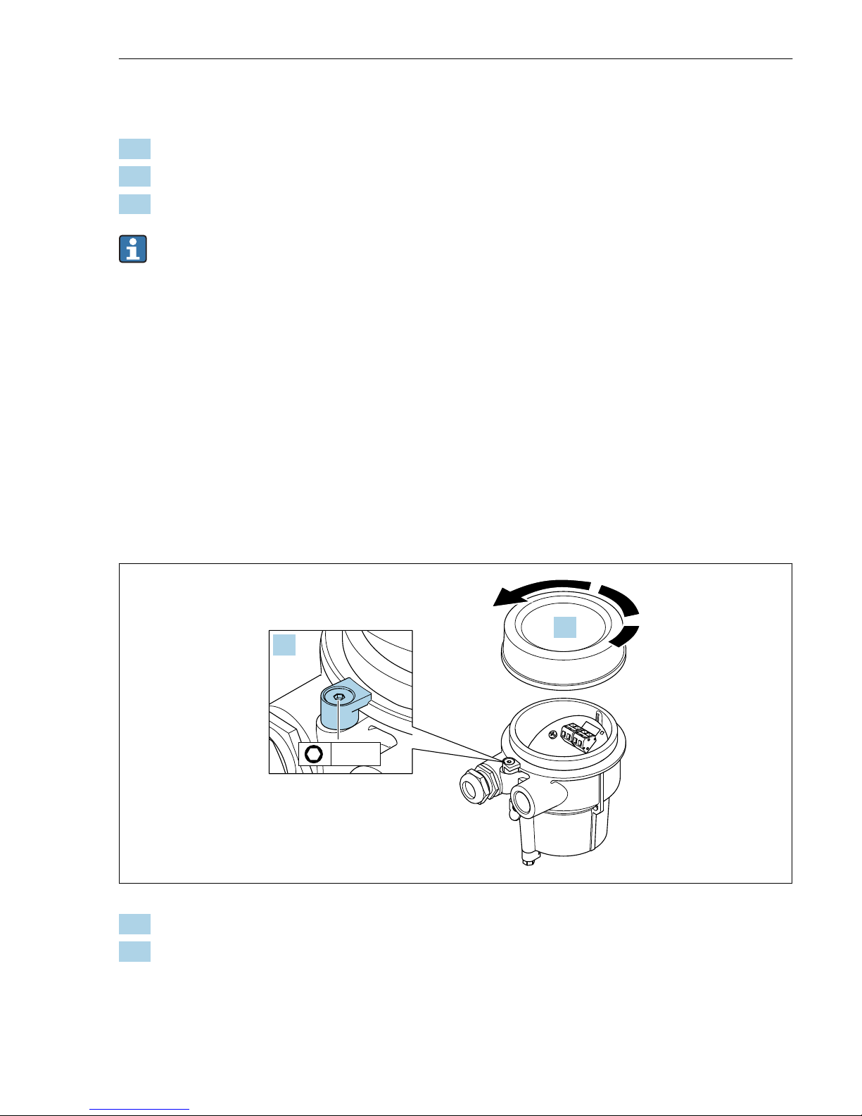
Connecting the sensor connection housing
3 mm
1.
2.
A0034167
1. Loosen the securing clamp.
2. Unscrew the housing cover.
Page 24
Electrical connection Proline 200 HART
24 Endress+Hauser
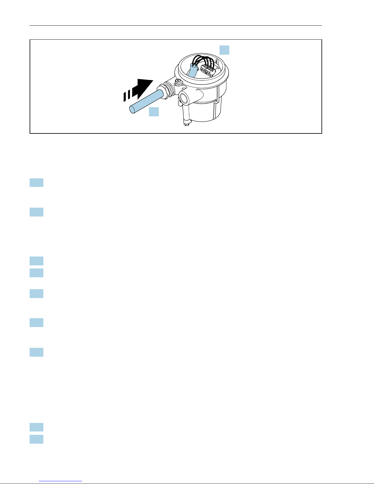
3.
4.
A0034171
6 Sample graphic
Connecting cable (standard, reinforced)
3. Guide the connecting cable through the cable entry and into the connection housing (if
using a connecting cable without an M12 device plug, use the shorter stripped end of
the connecting cable).
4. Wire the connecting cable:
Terminal 1 = brown cable
Terminal 2 = white cable
Terminal 3 = yellow cable
Terminal 4 = green cable
5. Connect the cable shield via the cable strain relief.
6. Tighten the screws for the cable strain relief using a torque in the range of
1.2 to 1.7 Nm.
7. Reverse the removal procedure to reassemble the connection housing.
Connecting cable (option "mass pressure-/temperature-compensated")
3. Guide the connecting cable through the cable entry and into the connection housing (if
using a connecting cable without an M12 device plug, use the shorter stripped end of
the connecting cable).
4. Wire the connecting cable:
Terminal 1 = brown cable
Terminal 2 = white cable
Terminal 3 = green cable
Terminal 4 = red cable
Terminal 5 = black cable
Terminal 6 = yellow cable
Terminal 7 = blue cable
5. Connect the cable shield via the cable strain relief.
6. Tighten the screws for the cable strain relief using a torque in the range of
1.2 to 1.7 Nm.
Page 25
Proline 200 HART Electrical connection
Endress+Hauser 25
7. Reverse the removal procedure to reassemble the connection housing.
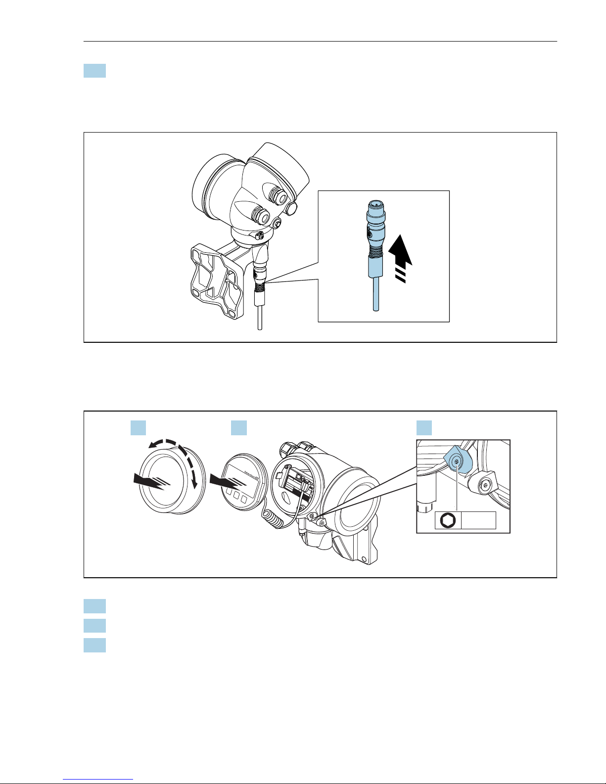
Connecting the transmitter
Connecting transmitter via plug
A0034172
‣
Connect the plug.
Connecting transmitter via terminals
+
E
–
3 mm
1.2. 3.
A0034173
1. Loosen the securing clamp of the electronics compartment cover.
2. Unscrew the electronics compartment cover.
3. Pull out the display module with a gentle rotational movement. To make it easier to
access the lock switch, attach the display module to the edge of the electronics
compartment.
Page 26
Electrical connection Proline 200 HART
26 Endress+Hauser
8 mm
TX 10
4.
5.
A0034174
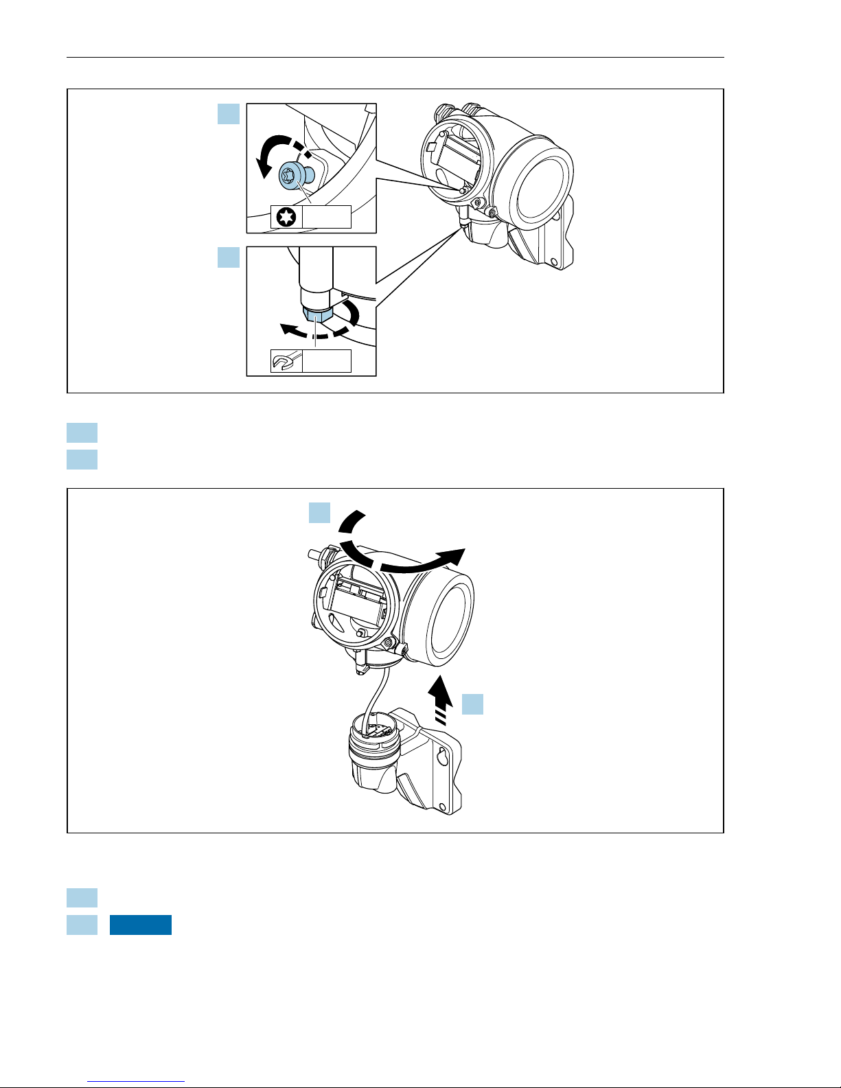
4. Loosen the locking screw of the transmitter housing.
5. Loosen the securing clamp of the transmitter housing.
~15°
6.
7.
A0034175
7 Sample graphic
6. Turn the transmitter housing to the right until it reaches the marking.
7.
NOTICE
The connection board of the wall housing is connected to the electronics board of
the transmitter via a signal cable!
‣
Pay attention to the signal cable when lifting the transmitter housing!
Lift the transmitter housing.
Page 27
Proline 200 HART Electrical connection
Endress+Hauser 27
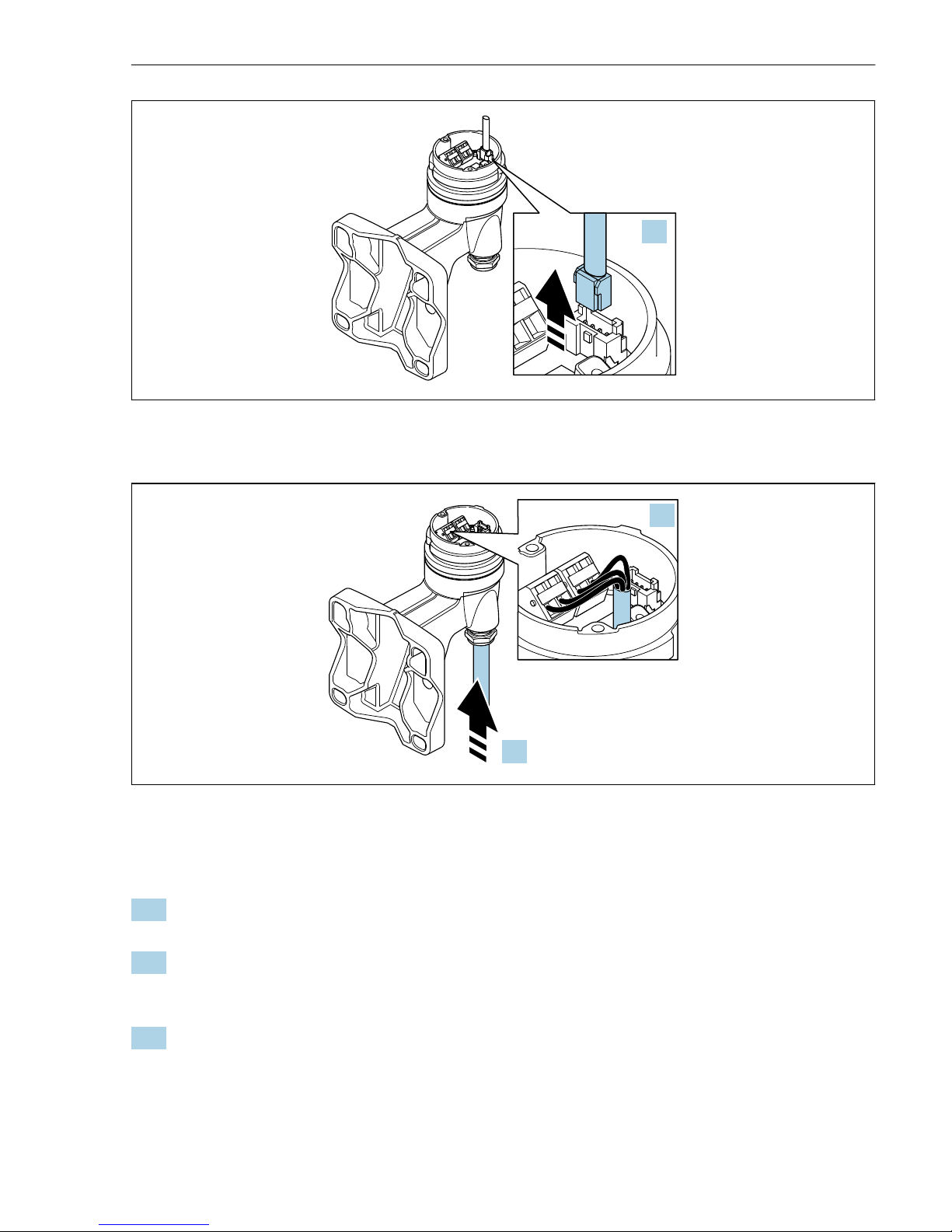
8.
A0034176
8 Sample graphic
9.
10.
A0034177
9 Sample graphic
Connecting cable (standard, reinforced)
8. Disconnect the signal cable from the connection board of the wall housing . by pressing
in the locking clip on the connector. Remove the transmitter housing.
9. Guide the connecting cable through the cable entry and into the connection housing (if
using a connecting cable without an M12 device plug, use the shorter stripped end of
the connecting cable).
10. Wire the connecting cable:
Terminal 1 = brown cable
Terminal 2 = white cable
Terminal 3 = yellow cable
Terminal 4 = green cable
Page 28

Electrical connection Proline 200 HART
28 Endress+Hauser
11. Connect the cable shield via the cable strain relief.
12. Tighten the screws for the cable strain relief using a torque in the range of
1.2 to 1.7 Nm.
13. Reverse the removal procedure to reassemble the transmitter housing.
Connecting cable (option "mass pressure-/temperature-compensated")
8. Disconnect both signal cables from the connection board of the wall housing. by
pressing in the locking clip on the connector. Remove the transmitter housing.
9. Guide the connecting cable through the cable entry and into the connection housing (if
using a connecting cable without an M12 device plug, use the shorter stripped end of
the connecting cable).
10. Wire the connecting cable:
Terminal 1 = brown cable
Terminal 2 = white cable
Terminal 3 = green cable
Terminal 4 = red cable
Terminal 5 = black cable
Terminal 6 = yellow cable
Terminal 7 = blue cable
11. Connect the cable shield via the cable strain relief.
12. Tighten the screws for the cable strain relief using a torque in the range of
1.2 to 1.7 Nm.
13. Reverse the removal procedure to reassemble the transmitter housing.
5.2.3 Connecting the connecting cable for the pressure measuring cell
When delivered to the customer, the connecting cable is connected as follows:
• Compact version: to transmitter housing
• Remote version: to sensor connection housing
For connection to sensor and pressure measuring cell:
‣
Insert M12 plug of connecting cable into pressure measuring cell and screw into place.
5.2.4 Ensuring potential equalization
Requirements
Please consider the following to ensure correct measurement:
• Same electrical potential for the medium and sensor
• Remote version: same electrical potential for the sensor and transmitter
• Company-internal grounding concepts
• Pipe material and grounding
5.3 Ensuring the degree of protection
The measuring device fulfills all the requirements for the IP66/67 degree of protection, Type
4X enclosure.
Page 29
Proline 200 HART Electrical connection
Endress+Hauser 29
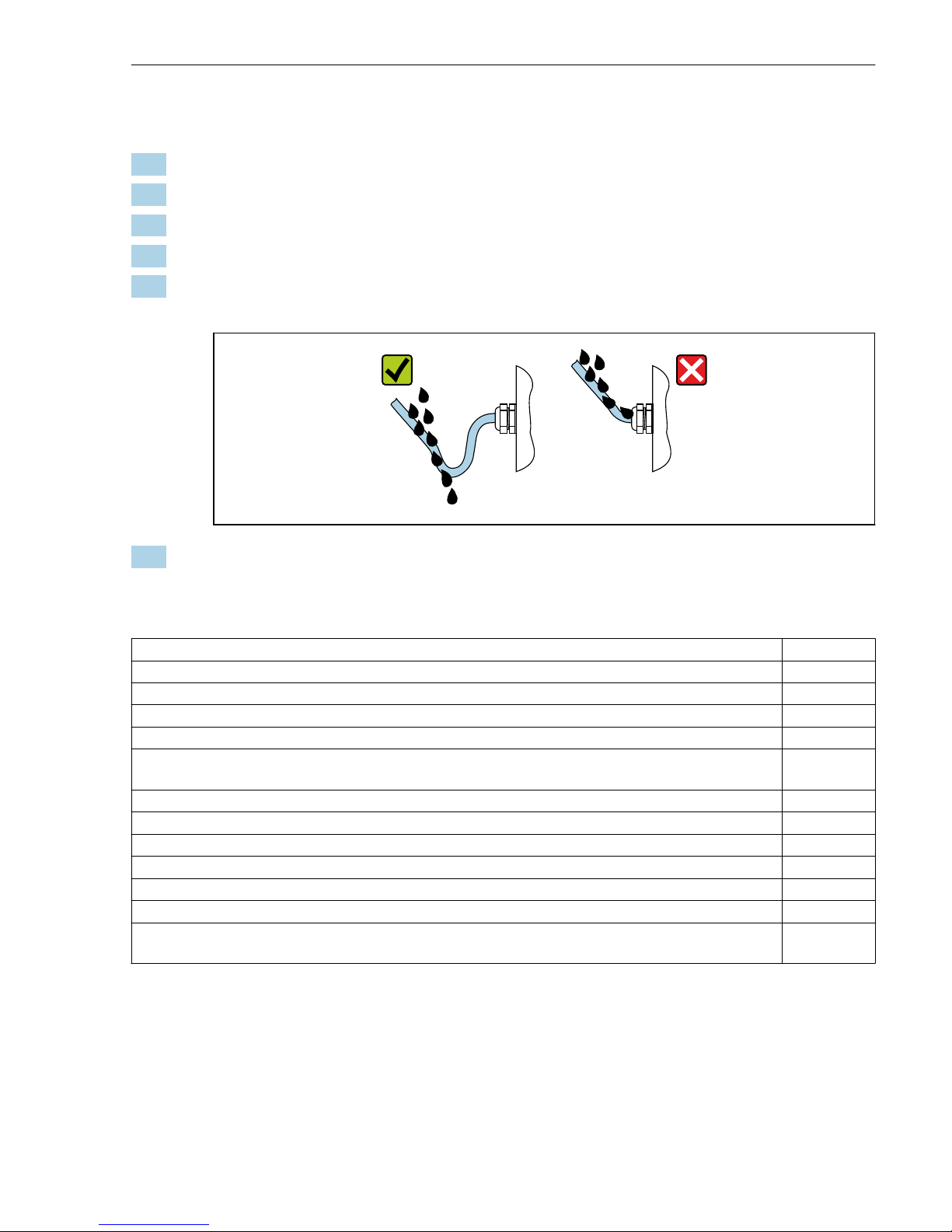
To guarantee IP66/67 degree of protection, Type 4X enclosure, carry out the following steps
after the electrical connection:
1. Check that the housing seals are clean and fitted correctly.
2. Dry, clean or replace the seals if necessary.
3. Tighten all housing screws and screw covers.
4. Firmly tighten the cable glands.
5. To ensure that moisture does not enter the cable entry:
Route the cable so that it loops down before the cable entry ("water trap").
A0029278
6. Insert dummy plugs into unused cable entries.
5.4 Post-connection check
Are cables or the device undamaged (visual inspection)?
Do the cables used meet the requirements→ 13?
Do the mounted cables have adequate strain relief?
Are all cable glands installed, securely tightened and leak-tight? Cable run with "water trap" → 28?
Depending on the device version, are all the device plugs firmly tightened→ 21?
Only for remote version: is the sensor connected to the right transmitter?
Check the serial number on the nameplate of the sensor and transmitter.
Does the supply voltage match the specifications on the transmitter nameplate→ 19?
Is the terminal assignment correct ?
If supply voltage is present, do values appear on the display module?
Are all the housing covers installed and tightened?
Is the securing clamp tightened correctly?
Have the screws for the cable strain relief been tightened using the correct torque→ 22?
Has the M12 plug of the connecting cable been correctly connected to the pressure measuring
cell→ 28?
Page 30
Operation options Proline 200 HART
30 Endress+Hauser
6 Operation options
6.1 Overview of operation options
1
2 3 4
E+-
ESC
5
6
A0032226
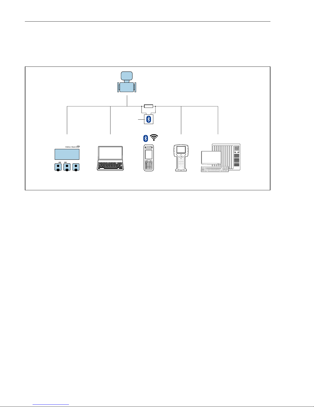
1 Local operation via display module
2 Computer with operating tool (e.g. FieldCare, DeviceCare, AMS Device Manager, SIMATIC PDM)
3 Field Xpert SFX350 or SFX370
4 Field Communicator 475
5 Control system (e.g. PLC)
6 VIATOR Bluetooth modem with connecting cable
Page 31
Proline 200 HART Operation options
Endress+Hauser 31
6.2 Structure and function of the operating menu
6.2.1 Structure of the operating menu
!
Expert
Operating menu for experts
Language
Operation
Setup
Diagnostics
Operating menu for operators and maintenances
Operator
Maintenance
task-oriented
function-oriented
Expert
A0014058-EN
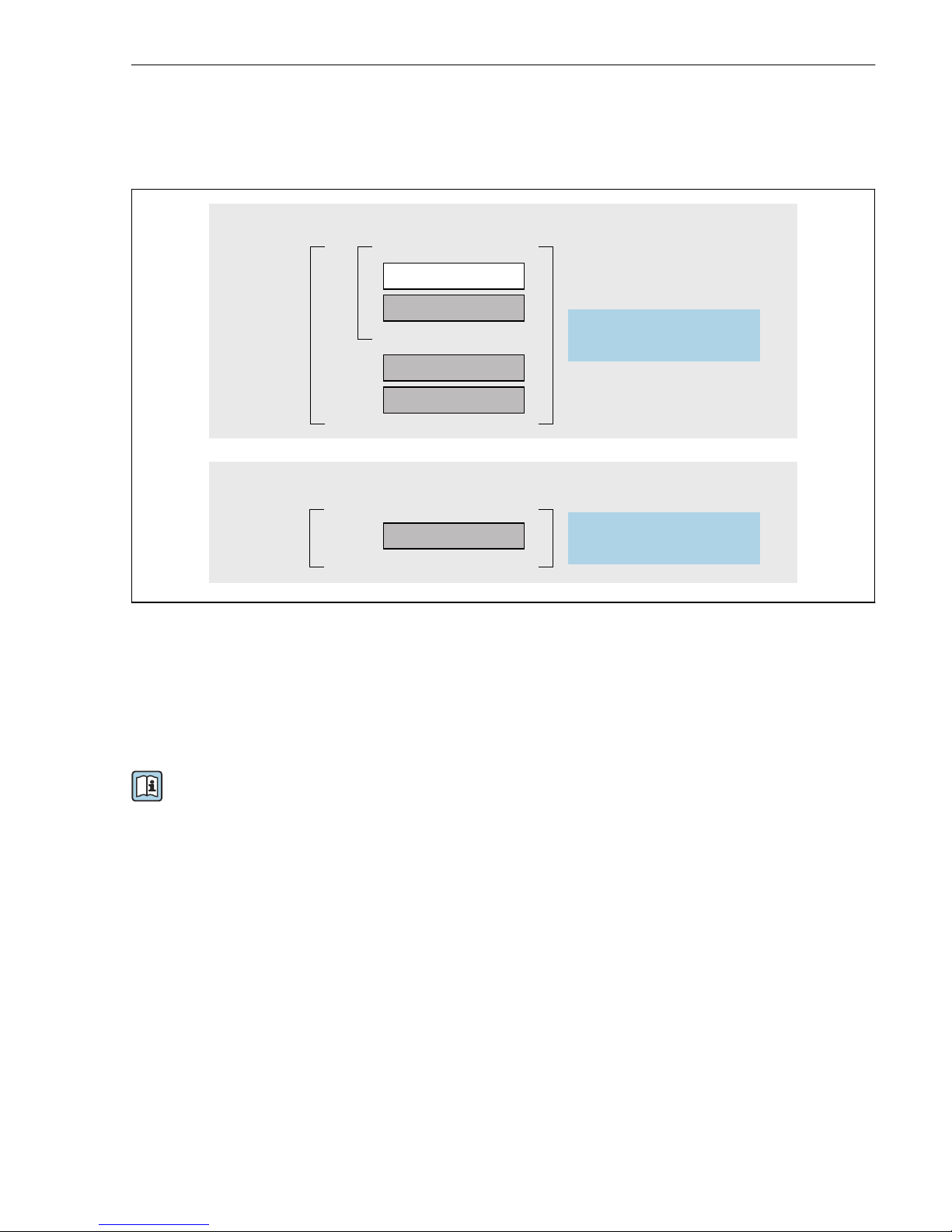
10 Schematic structure of the operating menu
6.2.2 Operating philosophy
The individual parts of the operating menu are assigned to certain user roles (operator,
maintenance etc.). Each user role contains typical tasks within the device lifecycle.
For detailed information on the operating philosophy, see the Operating Instructions for
the device.
Page 32
Operation options Proline 200 HART
32 Endress+Hauser
6.3 Access to the operating menu via the local display
5
4
2.1
2.2
2.4
2.5
2.3
2.6
2
X X X X X XX
l/s
19.184 mA
12.5
3.1
3.2
Ã
Español
Français
Language
English
Deutsch
3
1.5
1.6
ESC
E
X X XX XXX
20.50
S
mA
1.4
1.7
1
Xxxxxxx
A B C D E F G H I J K
M N O P Q R S T U V W
X YLZ
+0.000 Xx
0 1 2 3 4
+
5
6 7
8
9
–
A0014013
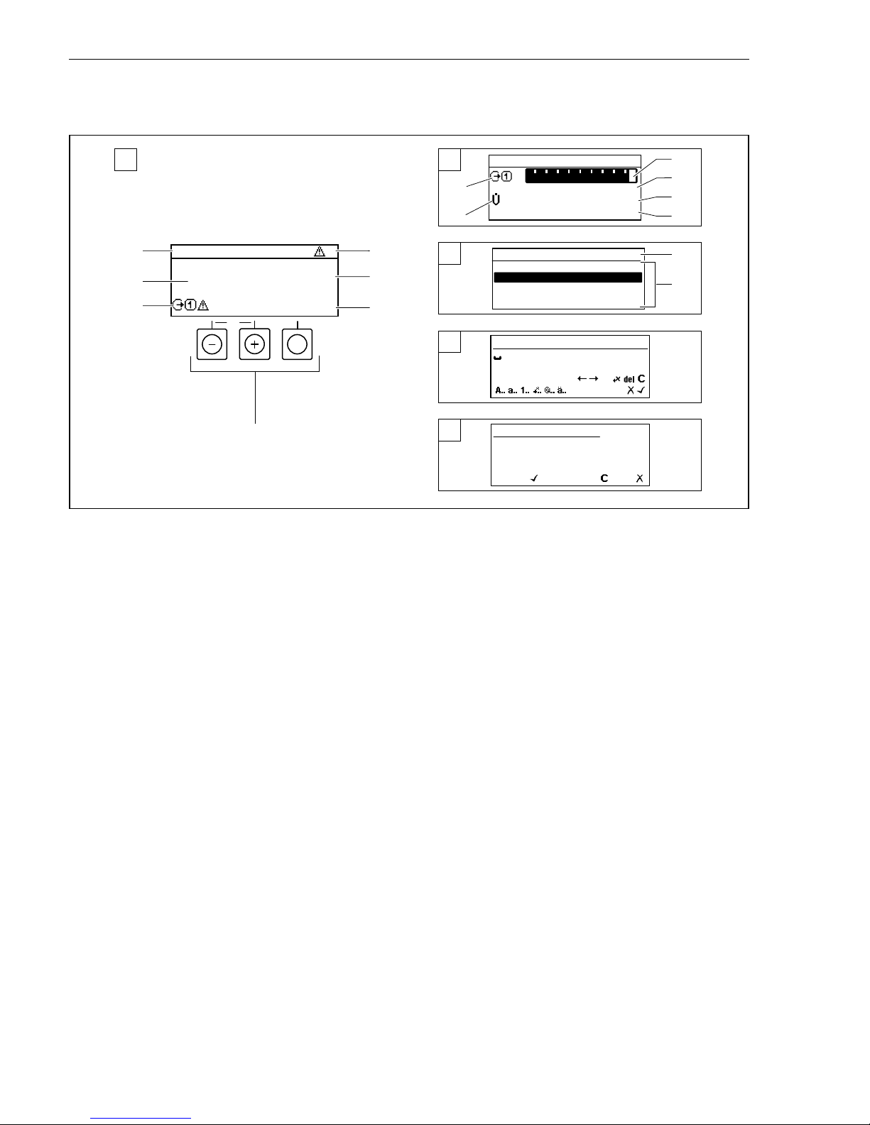
1 Operational display with measured value shown as "1 value, max." (example)
1.1 Device tag
1.2 Display area for measured values (4-line)
1.3 Explanatory symbols for measured value: Measured value type, measuring channel number, symbol
for diagnostic behavior
1.4 Status area
1.5 Measured value
1.6 Unit for the measured value
1.7 Operating elements
2 Operational display with measured value shown as "1 bar graph + 1 value" (example)
2.1 Bar graph display for measured value 1
2.2 Measured value 1 with unit
2.3 Explanatory symbols for measured value 1: measured value type, measuring channel number
2.4 Measured value 2
2.5 Unit for measured value 2
2.6 Explanatory symbols for measured value 2: measured value type, measuring channel number
3 Navigation view: picklist of a parameter
3.1 Navigation path and status area
3.2 Display area for navigation: designates the current parameter value
4 Editing view: text editor with input mask
5 Editing view: numeric editor with input mask
Page 33
Proline 200 HART Operation options
Endress+Hauser 33
6.3.1 Operational display
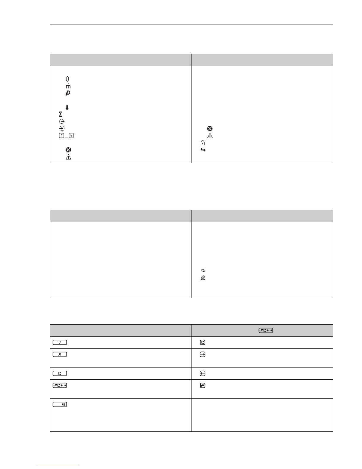
Explanatory symbols for the measured value Status area
• Depends on the device version, e.g.:
– : Volume flow
– : Mass flow
– : Density
– G: Conductivity
– : Temperature
• : Totalizer
• : Output
• : Input
• : Measurement channel number
1)
• Diagnostic behavior
2)
– : Alarm
– : Warning
The following symbols appear in the status area of the
operational display at the top right:
• Status signals
– F: Failure
– C: Function check
– S: Out of specification
– M: Maintenance required
• Diagnostic behavior
– : Alarm
– : Warning
• : Locking (locked via hardware))
• : Communication via remote operation is active.
1) If there is more than one channel for the same measured variable type (totalizer, output etc.).
2) For a diagnostic event that concerns the displayed measured variable.
6.3.2 Navigation view
Status area Display area
The following appears in the status area of the navigation
view in the top right corner:
• In the submenu
– The direct access code for the parameter you are
navigating to (e.g. 0022-1)
– If a diagnostic event is present, the diagnostic
behavior and status signal
• In the wizard
If a diagnostic event is present, the diagnostic behavior
and status signal
• Icons for menus
– : Operation
– : Setup
– : Diagnostics
– : Expert
• ▸: Submenus
• : Wizards
• : Parameters within a wizard
• : Parameter locked
6.3.3 Editing view
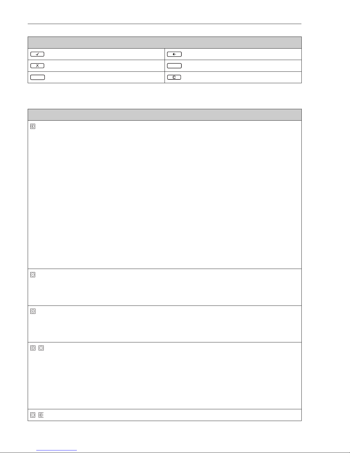
Text editor Correction symbols under
Confirms selection. Clears all entered characters.
Exits the input without applying the changes. Moves the input position one position to the
right.
Clears all entered characters. Moves the input position one position to the left.
Switches to the selection of the correction tools. Deletes one character immediately to the left of
the input position.
Aa1
Toggle
• Between upper-case and lower-case letters
• For entering numbers
• For entering special characters
Page 34
Operation options Proline 200 HART
34 Endress+Hauser
Numeric editor
Confirms selection. Moves the input position one position to the left.
Exits the input without applying the changes.
.
Inserts decimal separator at the input position.
–
Inserts minus sign at the input position. Clears all entered characters.
6.3.4 Operating elements
Keys and meaning
Enter key
For operational display
• Pressing the key briefly opens the operating menu.
• Pressing the key for 2 s opens the context menu.
In a menu, submenu
• Pressing the key briefly
– Opens the selected menu, submenu or parameter.
– Starts the wizard.
– If help text is open:
Closes the help text of the parameter.
• Pressing the key for 2 s for parameter:
If present, opens the help text for the function of the parameter.
With a wizard: Opens the editing view of the parameter.
With a text and numeric editor:
• Pressing the key briefly
– Opens the selected group.
– Carries out the selected action.
• Pressing the key for 2 s:
Confirms the edited parameter value.
Minus key
• In a menu, submenu: Moves the selection bar upwards in a choose list.
• With a wizard: Confirms the parameter value and goes to the previous parameter.
• With a text and numeric editor: Moves the selection bar to the left (backwards) in an input screen.
Plus key
• In a menu, submenu: Moves the selection bar downwards in a choose list.
• With a wizard: Confirms the parameter value and goes to the next parameter.
• With a text and numeric editor: Moves the selection bar to the right (forwards) in an input screen.
+ Escape key combination (press keys simultaneously)
In a menu, submenu
• Pressing the key briefly
– Exits the current menu level and takes you to the next higher level.
– If help text is open, closes the help text of the parameter.
• Pressing the key for 2 s for the parameter: Returns you to the operational display ("home position").
With a wizard: Exits the wizard and takes you to the next higher level.
With a text and numeric editor: Closes the text or numeric editor without applying changes.
+ Minus/Enter key combination (press the keys simultaneously)
Page 35
Proline 200 HART System integration
Endress+Hauser 35
Keys and meaning
Reduces the contrast (brighter setting).
+ Plus/Enter key combination (press and hold down the keys simultaneously)
Increases the contrast (darker setting).
+ + Minus/Plus/Enter key combination (press the keys simultaneously)
For operational display:Enables or disables the keypad lock.
6.3.5 Further information
For further information on the following topics, see the Operating Instructions for the
device
• Calling up help text
• User roles and related access authorization
• Disabling write protection via access code
• Enabling and disabling the keypad lock
6.4 Access to the operating menu via the operating tool
The operating menu can also be accessed via the FieldCare and DeviceCare operating
tools. See the Operating Instructions for the device.
7 System integration
For detailed information on system integration, see the Operating Instructions for the
device.
• Overview of device description files:
– Current version data for the device
– Operating tools
• Measured variables via HART protocol
• Burst mode functionality in accordance with HART 7 Specification
8 Commissioning
8.1 Function check
Before commissioning the measuring device:
‣
Make sure that the post-installation and post-connection checks have been performed.
• "Post-installation check" checklist→ 12
• "Post-connection check" checklist → 29
Page 36
Commissioning Proline 200 HART
36 Endress+Hauser
8.2 Switching on the measuring device
‣
After a successful function check, switch on the measuring device.
After a successful startup, the local display switches automatically from the startup
display to the operational display.
If nothing appears on the local display or a diagnostic message is displayed, refer to the
Operating Instructions for the device → 2
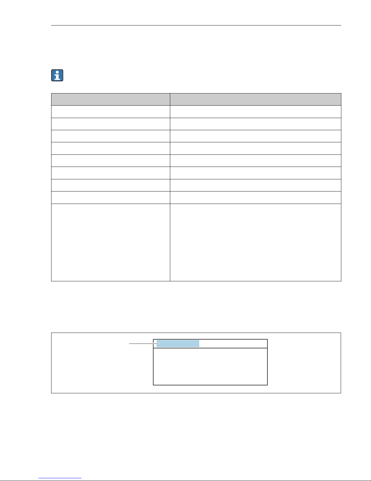
8.3 Setting the operating language
Factory setting: English or ordered local language
X XX X X X XX X
20.50
Operation
Setup
Main menu
0104-1
Display language
English
Español
Français
Display language
English
Deutsch
Ã
0104-1
Ã
Español
Français
Display language
English
Deutsch
0104-1
Betrieb
Setup
Hauptmenü
Sprache
Deutsch
0104-1
XXXX
1.
2.
3.
4.
A0029420
11 Taking the example of the local display
8.4 Configuring the measuring device
The Setup menu with its System units submenu and various guided wizards enable fast
commissioning of the measuring device.
Page 37
Proline 200 HART Commissioning
Endress+Hauser 37
The desired units can be selected in the System units submenu. The wizards systematically
guide the user through all the parameters required for configuration, such as parameters for
measurement or outputs.
The wizards available in the particular device can vary on account of the device version
(e.g. sensor).
Wizard Meaning
System units Configure the units for all measured variables
Medium selection Define the medium
Current input Configure the current input
Current output 1 to n Set current output 1-2
Pulse/frequency/switch output Configure the selected output type
Display Configure the measured value display
Output conditioning Define the output conditioning
Low flow cut off Set the low flow cut off
Advanced setup Additional parameters for configuration:
• Medium properties
• External compensation
• Sensor adjustment
• Totalizer 1 to n
• SIL confirmation
• Deactivate SIL
• Heartbeat
• Configuration backup display
• Administration
8.5 Defining the tag name
To enable fast identification of the measuring point within the system, you can enter a unique
designation using the Device tag parameter and thus change the factory setting.
1
XXXXXXXXX
A0029422
12 Header of the operational display with tag name
1 Tag name
Navigation
"Setup" menu → Device tag
Page 38
Commissioning Proline 200 HART
38 Endress+Hauser
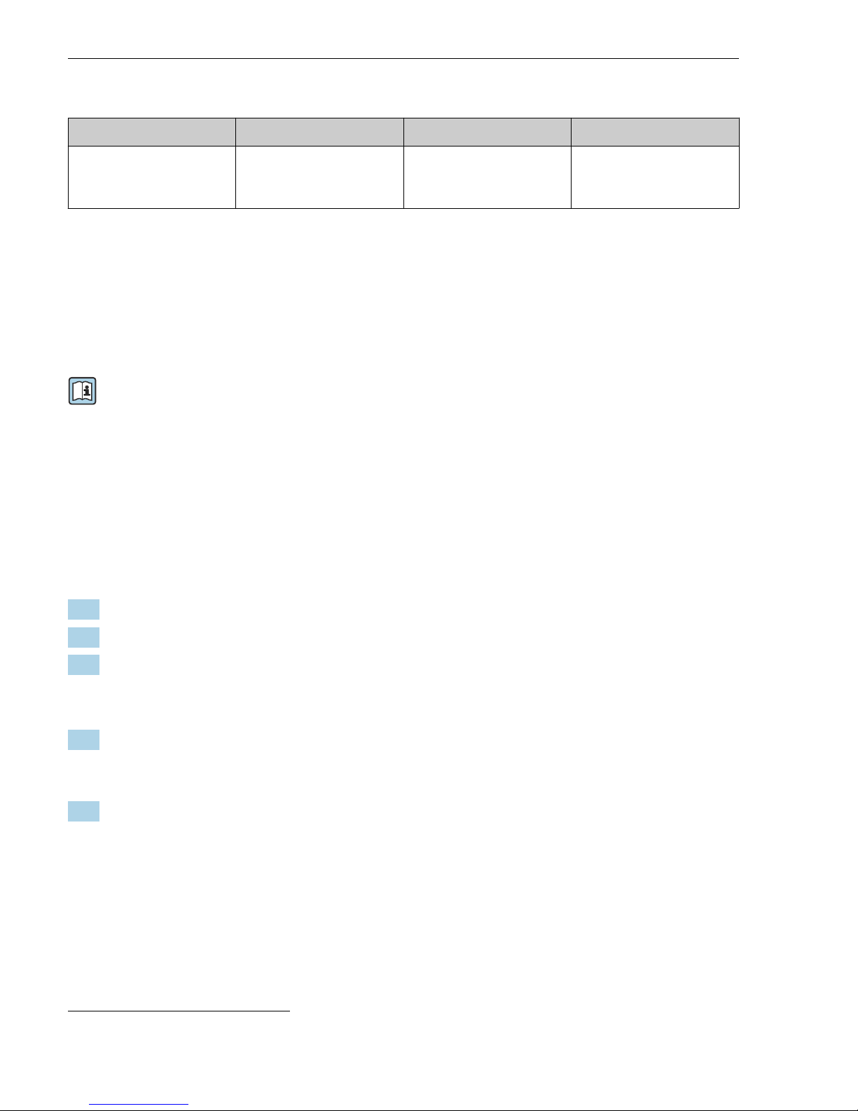
Parameter overview with brief description
Parameter Description User entry Factory setting
Device tag Enter the name for the
measuring point.
Max. 32 characters, such as
letters, numbers or special
characters (e.g. @, %, /).
Prowirl
8.6 Protecting settings from unauthorized access
The following write protection options exist in order to protect the configuration of the
measuring device from unintentional modification:
• Protect access to parameters via access code
• Protect access to local operation via key locking
• Protect access to measuring device via write protection switch
For detailed information on protecting the settings against unauthorized access, see the
Operating Instructions for the device.
8.7 Application-specific commissioning
8.7.1 Steam application
Select medium
Navigation:
Setup → Medium selection
1. Call up the Medium selection wizard.
2. In the Select medium parameter, select the Steam option.
3.
When pressure measured value is read in
1)
:
In the Steam calculation mode parameter, select the Automatic (p-/T-compensated)
option.
4. If pressure measured value is not read in:
In the Steam calculation mode parameter, select the Saturated steam (T-
compensated) option.
5. In the Steam quality value parameter, enter the steam quality present in the pipe.
Without Wet Steam Detection/Measurement application package: Measuring
device uses this value to calculate the mass flow of the steam.
With Wet Steam Detection/Measurement application package: Measuring device
uses this value if the steam quality cannot be calculated (steam quality is not
compliant with basic conditions).
1) Sensor version option "mass (integrated pressure and temperature measurement)", Pressure read in via current
input/HART/
Page 39

Proline 200 HART Commissioning
Endress+Hauser 39
Configuring the current output
6. Configure current output.
Configuring the external compensation
7. With Wet Steam Detection/Measurement application package:
In the Steam quality parameter, select the Calculated value option.
For detailed information on the basic conditions for wet steam applications, see the
Special Documentation.
8.7.2 Liquid application
User-specific liquid, e. g. heat carrier oil
Select medium
Navigation:
Setup → Medium selection
1. Call up the Medium selection wizard.
2. In the Select medium parameter, select the Liquid option.
3. In the Select liquid type parameter, select the User-specific liquid option.
4. In the Enthalpy type parameter, select the Heat option.
Heat option: Non-flammable liquid that serves as a heat carrier.
Calorific value option: Flammable liquid whose combustion energy is calculated.
Configuring fluid properties
Navigation:
Setup → Advanced setup → Medium properties
5. Call up the Medium properties submenu.
6. In the Reference density parameter, enter the reference density of the fluid.
7. In the Reference temperature parameter, enter the fluid temperature associated with
the reference density.
8. In the Linear expansion coefficient parameter, enter the expansion coefficient of the
fluid.
9. In the Specific heat capacity parameter, enter the heat capacity of the fluid.
10. In the Dynamic viscosity parameter, enter the viscosity of the fluid.
Page 40

Commissioning Proline 200 HART
40 Endress+Hauser
8.7.3 Gas applications
For accurate mass or corrected volume measurement, it is recommended to use the
pressure-/temperature-compensated sensor version. If this sensor version is not
available, read in the pressure via the current input/HART. If neither of these two
options is possible, the pressure can also be entered as a fixed value in the Fixed process
pressure parameter.
Flow computer available only with the order code for "Sensor version", option "mass"
(integrated temperature measurement)" or option "mass (integrated pressure/
temperature measurement)".
Single gas
Combustion gas, e. g. methane CH
4
Select medium
Navigation:
Setup → Medium selection
1. Call up the Medium selection wizard.
2. In the Select medium parameter, select the Gas option.
3. In the Select gas type parameter, select the Single gas option.
4. In the Gas type parameter, select the Methane CH4 option.
Configuring fluid properties
Navigation:
Setup → Advanced setup → Medium properties
5. Call up the Medium properties submenu.
6. In the Reference combustion temperature parameter, enter the reference combustion
temperature of the fluid.
7.
Configuring the current output
8. Configure the current output for the "energy flow" process variable.
Configuring optional fluid properties for output of corrected volume flow
Navigation:
Setup → Advanced setup → Medium properties
9. Call up the Medium properties submenu.
10. In the Reference pressure parameter, enter the reference pressure of the fluid.
11. In the Reference temperature parameter, enter the reference temperature of the fluid.
Page 41

Proline 200 HART Commissioning
Endress+Hauser 41
Gas mixture
Forming gas for steel mills and rolling mills, e. g. N2/H
2
Select medium
Navigation:
Setup → Medium selection
1. Call up the Medium selection wizard.
2. In the Select medium parameter, select the Gas option.
3. In the Select gas type parameter, select the Gas mixture option.
Configuring gas composition
Navigation:
Setup → Advanced setup → Medium properties → Gas composition
4. Call up the Gas composition submenu.
5. In the Gas mixture parameter, select the Hydrogen H2 option and the Nitrogen N2
option.
6. In the Mol% H2 parameter, enter the quantity of hydrogen.
7. In the Mol% N2 parameter, enter the quantity of nitrogen.
All quantities must add up to 100 %.
The density is determined according to NEL 40.
Configuring optional fluid properties for output of corrected volume flow
Navigation:
Setup → Advanced setup → Medium properties
8. Call up the Medium properties submenu.
9. In the Reference pressure parameter, enter the reference pressure of the fluid.
10. In the Reference temperature parameter, enter the reference temperature of the fluid.
Air
Select medium
Navigation:
Setup → Medium selection
1. Call up the Medium selection wizard.
2. In the Select medium parameter, select the Gas option.
3. In the Select gas type parameter, select the Air option.
The density is determined according to NEL 40.
Page 42

Commissioning Proline 200 HART
42 Endress+Hauser
4. Enter the value in the Relative humidity parameter.
The relative humidity is entered as a %. The relative humidity is converted
internally to absolute humidity and is then factored into the density calculation
according to NEL 40.
5. In the Fixed process pressure parameter, enter the value of the process pressure
present.
Configuring fluid properties
Navigation:
Setup → Advanced setup → Medium properties
6. Call up the Medium properties submenu.
7. In the Reference pressure parameter enter the reference pressure for calculating the
reference density.
Pressure that is used as a static reference for combustion. This makes it possible to
compare combustion processes at different pressures.
8. In the Reference temperature parameter enter the temperate for calculating the
reference density.
Endress+Hauser recommends the use of active pressure compensation. This fully rules
out the risk of measured errors due to pressure variations and incorrect entries .
Natural gas
Select medium
Navigation:
Setup → Medium selection
1. Call up the Medium selection wizard.
2. In the Select medium parameter, select the Gas option.
3. In the Select gas type parameter, select the Natural gas option.
4. In the Fixed process pressure parameter, enter the value of the process pressure
present.
5. In the Enthalpy calculation parameter, select one of the following options:
AGA5
ISO 6976 option (contains GPA 2172)
6. In the Density calculation parameter, select one of the following options.
AGA Nx19
ISO 12213- 2 option (contains AGA8-DC92)
ISO 12213- 3 option (contains SGERG-88, AGA8 Gross Method 1)
Configuring fluid properties
Navigation:
Page 43
Proline 200 HART Commissioning
Endress+Hauser 43
Setup → Advanced setup → Medium properties
7. Call up the Medium properties submenu.
8. In the Calorific value type parameter, select one of the options.
9. n the Reference gross calorific value parameter, enter the reference gross calorific
value of the natural gas.
10. In the Reference pressure parameter enter the reference pressure for calculating the
reference density.
Pressure that is used as a static reference for combustion. This makes it possible to
compare combustion processes at different pressures.
11. In the Reference temperature parameter enter the temperate for calculating the
reference density.
12. In the Relative density parameter, enter the relative density of the natural gas.
Endress+Hauser recommends the use of active pressure compensation. This fully rules
out the risk of measured errors due to pressure variations and incorrect entries .
Ideal gas
The unit "corrected volume flow" is often used to measure industrial gas mixtures, in particular
natural gas. To do so, the calculated mass flow is divided by a reference density. To calculate
the mass flow, knowledge of the exact composition of the gas is essential. In practice,
however, this information is often not available (e. g. as it varies over time). In this case, it can
be useful to regard the gas as an ideal gas. This means that only the operating temperature
and operating pressure variables as well as the reference temperature and reference pressure
variables are needed to calculate the corrected volume flow. The error resulting from this
assumption (typically 1 to 5 %) is often considerably smaller than the error caused by
inaccurate composition data. This method should not be used for condensing gases (e. g.
saturated steam).
Select medium
Navigation:
Setup → Medium selection
1. Call up the Medium selection wizard.
2. In the Select medium parameter, select the Gas option.
3. In the Select gas type parameter, select the User-specific gas option.
4. For non-flammable gas:
In the Enthalpy type parameter, select the Heat option.
Configuring fluid properties
Navigation:
Setup → Advanced setup → Medium properties
5. Call up the Medium properties submenu.
Page 44

Diagnostic information Proline 200 HART
44 Endress+Hauser
6. In the Reference density parameter, enter the reference density of the fluid.
7. In the Reference pressure parameter, enter the reference pressure of the fluid.
8. In the Reference temperature parameter, enter the fluid temperature associated with
the reference density.
9. In the Reference Z-factor parameter, enter the value 1.
10. If specific heat capacity is to be measured:
In the Specific heat capacity parameter, enter the heat capacity of the fluid.
11. In the Z-factor parameter, enter the value 1.
12. In the Dynamic viscosity parameter, enter the viscosity of the fluid under operating
conditions.
9 Diagnostic information
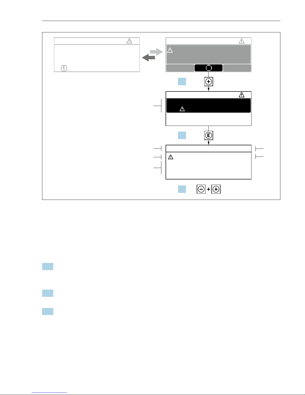
Faults detected by the self-monitoring system of the measuring device are displayed as a
diagnostic message in alternation with the operational display. The message on remedial
measures can be called up from the diagnostic message, and contains important information
on the fault.
Page 45
Proline 200 HART Diagnostic information
Endress+Hauser 45
X XX X X XXX X X XX X X XXX X
S
S
XX
20.50
X
i
S801
Menu
S
(ID:203)
S801 0d00h02m25s
1
2
4
6
3
5
1.
2.
3.
Increase supply voltage
S801 Supply voltage
Diagnostic list
Diagnostics 1
Diagnostics 2
Diagnostics 3
Supply voltage
Supply voltage
A0029431-EN
13 Message about remedial measures
1 Diagnostic information
2 Short text
3 Service ID
4 Diagnostic behavior with diagnostic code
5 Operation time of occurrence
6 Remedial measures
1. The user is in the diagnostic message.
Press ( symbol).
The Diagnostic list submenu opens.
2. Select the desired diagnostic event with or and press .
The message about the remedial measures opens.
3. Press + simultaneously.
The message about the remedial measures closes.
Page 46

Page 47

Page 48

www.addresses.endress.com
 Loading...