

Page 1

BA01449D/06/EN/03.16
Power
Error
ESC
E
+
-
71311429
Valid as of version
V 3.00.9 (device software)
V 3.01.3 (Nanomass Communication)
Products Solutions Services
Operating Instructions
Nanomass Gas Density
MEMS Coriolis density meter
Page 2

Nanomass Gas Density
• Make sure the Operating Instructions are stored in a safe place such that they are always
available when working on or with the measuring device.
• To avoid danger to individuals or the facility, read the "Basic safety instructions" section
carefully, as well as all other safety instructions in the Operating Instructions that are
specific to working procedures.
• The manufacturer reserves the right to modify technical data without prior notice. Your
Endress+Hauser Sales Center will supply you with current information and updates to
these Operating Instructions.
2 Endress+Hauser
Page 3

Nanomass Gas Density
Table of contents
1 Notes on the Operating Instructions. . . 5
1.1 Document function . . . . . . . . . . . . . . . . . . . . . . . . . . 5
1.2 Symbols used . . . . . . . . . . . . . . . . . . . . . . . . . . . . . . . 5
1.3 Technical documentation . . . . . . . . . . . . . . . . . . . . . 6
1.4 Registered trademarks . . . . . . . . . . . . . . . . . . . . . . . 7
2 Basic safety instructions . . . . . . . . . . . . . 8
2.1 Requirements for personnel . . . . . . . . . . . . . . . . . . 8
2.2 Designated use . . . . . . . . . . . . . . . . . . . . . . . . . . . . . 8
2.3 Occupational safety . . . . . . . . . . . . . . . . . . . . . . . . . . 9
2.4 Operational safety . . . . . . . . . . . . . . . . . . . . . . . . . . . 9
2.5 Product safety . . . . . . . . . . . . . . . . . . . . . . . . . . . . . . 9
2.6 IT security . . . . . . . . . . . . . . . . . . . . . . . . . . . . . . . . . . 9
3 Product description . . . . . . . . . . . . . . . . 10
3.1 Product design . . . . . . . . . . . . . . . . . . . . . . . . . . . . 10
4 Incoming acceptance and product
identification . . . . . . . . . . . . . . . . . . . . . 11
4.1 Incoming acceptance . . . . . . . . . . . . . . . . . . . . . . 11
4.2 Product identification . . . . . . . . . . . . . . . . . . . . . . 11
5 Storage, transportation, disposal of
packaging . . . . . . . . . . . . . . . . . . . . . . . . 14
5.1 Storage conditions . . . . . . . . . . . . . . . . . . . . . . . . 14
5.2 Transporting the product . . . . . . . . . . . . . . . . . . . 14
5.3 Disposal of packaging . . . . . . . . . . . . . . . . . . . . . . 14
6 Installation . . . . . . . . . . . . . . . . . . . . . . . 15
10 Commissioning . . . . . . . . . . . . . . . . . . . 36
10.1 Installation and function check . . . . . . . . . . . . . . . 36
10.2 Switching on the measuring device . . . . . . . . . . . 36
10.3 Setting the operating language . . . . . . . . . . . . . . 36
10.4 Configuring the measuring device . . . . . . . . . . . . 36
10.5 Advanced settings . . . . . . . . . . . . . . . . . . . . . . . . . 41
10.6 Simulation . . . . . . . . . . . . . . . . . . . . . . . . . . . . . . . . 43
10.7 "Datalog Function" application package . . . . . . . . 43
10.8 "Concentration Measurement" application package
44
11 Operation . . . . . . . . . . . . . . . . . . . . . . . . 47
11.1 Changing the operating language . . . . . . . . . . . . 47
11.2 Configuring the local display . . . . . . . . . . . . . . . . . 47
11.3 Reading measured values on the local display . . 47
11.4 Accessing real-time measuring data . . . . . . . . . . 48
11.5 Retrieving measuring data . . . . . . . . . . . . . . . . . . 51
11.6 Adapting the measuring device to the process
conditions . . . . . . . . . . . . . . . . . . . . . . . . . . . . . . . . 52
11.7 Updating the firmware . . . . . . . . . . . . . . . . . . . . . 53
12 Diagnostics and troubleshooting . . . . 54
12.1 General troubleshooting . . . . . . . . . . . . . . . . . . . . 54
12.2 Diagnostic information via light emitting diodes . .
55
12.3 Diagnostic information on local display . . . . . . . . 55
12.4 Diagnostic information in the operating tool . . . 56
12.5 Resetting the measuring device to factory default
settings . . . . . . . . . . . . . . . . . . . . . . . . . . . . . . . . . . . 56
12.6 Performing density adjustment with air . . . . . . . 57
12.7 Device information . . . . . . . . . . . . . . . . . . . . . . . . . 57
6.1 Installation conditions . . . . . . . . . . . . . . . . . . . . . 15
6.2 Mounting the measuring device . . . . . . . . . . . . . 18
6.3 Post-installation check . . . . . . . . . . . . . . . . . . . . . 19
7 Electrical connection . . . . . . . . . . . . . . . 20
7.1 Connection conditions . . . . . . . . . . . . . . . . . . . . . 20
7.2 Connecting the measuring device . . . . . . . . . . . . 22
7.3 Special connection instructions . . . . . . . . . . . . . . 24
7.4 Guaranteeing the degree of protection . . . . . . . 24
7.5 Post-connection check . . . . . . . . . . . . . . . . . . . . . 25
8 Operating options . . . . . . . . . . . . . . . . .26
8.1 Overview of operating options . . . . . . . . . . . . . . 26
8.2 Access to the measuring device via the local display
26
8.3 Access to the measuring device via the
"Nanomass Communication" operating tool . . . . 28
9 System integration. . . . . . . . . . . . . . . . . 34
9.1 Overview of device description files . . . . . . . . . . 34
9.2 Measured variables via serial interface . . . . . . . 34
13 Maintenance . . . . . . . . . . . . . . . . . . . . . 59
13.1 Maintenance tasks . . . . . . . . . . . . . . . . . . . . . . . . . 59
13.2 Measuring and test equipment . . . . . . . . . . . . . . . 59
13.3 Endress+Hauser services . . . . . . . . . . . . . . . . . . . . 60
14 Repair . . . . . . . . . . . . . . . . . . . . . . . . . . . 61
14.1 General notes . . . . . . . . . . . . . . . . . . . . . . . . . . . . . 61
14.2 Spare parts . . . . . . . . . . . . . . . . . . . . . . . . . . . . . . . . 61
14.3 Endress+Hauser services . . . . . . . . . . . . . . . . . . . . 61
14.4 Return . . . . . . . . . . . . . . . . . . . . . . . . . . . . . . . . . . . 61
14.5 Disposal . . . . . . . . . . . . . . . . . . . . . . . . . . . . . . . . . . 62
15 Accessories. . . . . . . . . . . . . . . . . . . . . . . 63
15.1 Device-specific accessories . . . . . . . . . . . . . . . . . . 63
15.2 Service-specific accessories . . . . . . . . . . . . . . . . . 63
15.3 System components . . . . . . . . . . . . . . . . . . . . . . . . 64
16 Technical data . . . . . . . . . . . . . . . . . . . . 65
16.1 Application . . . . . . . . . . . . . . . . . . . . . . . . . . . . . . . 65
16.2 Function and system design . . . . . . . . . . . . . . . . . 65
Endress+Hauser 3
Page 4

Nanomass Gas Density
16.3 Input . . . . . . . . . . . . . . . . . . . . . . . . . . . . . . . . . . . . . 65
16.4 Output . . . . . . . . . . . . . . . . . . . . . . . . . . . . . . . . . . . 65
16.5 Power supply . . . . . . . . . . . . . . . . . . . . . . . . . . . . . . 66
16.6 Performance characteristics . . . . . . . . . . . . . . . . . 67
16.7 Installation . . . . . . . . . . . . . . . . . . . . . . . . . . . . . . . 68
16.8 Environment . . . . . . . . . . . . . . . . . . . . . . . . . . . . . . 68
16.9 Process . . . . . . . . . . . . . . . . . . . . . . . . . . . . . . . . . . . 69
16.10 Mechanical construction . . . . . . . . . . . . . . . . . . . . 71
16.11 Operability . . . . . . . . . . . . . . . . . . . . . . . . . . . . . . . . 72
16.12 Certificates and approvals . . . . . . . . . . . . . . . . . . . 73
16.13 Application packages . . . . . . . . . . . . . . . . . . . . . . . 73
16.14 Accessories . . . . . . . . . . . . . . . . . . . . . . . . . . . . . . . 74
16.15 Documentation . . . . . . . . . . . . . . . . . . . . . . . . . . . . 74
17 Appendix . . . . . . . . . . . . . . . . . . . . . . . . .75
17.1 Overview of the device parameters . . . . . . . . . . . 75
17.2 Menu "Measuring variables" "Main values" . . . 76
17.3 Menu "Measuring variables" "System units" . . . 77
17.4 Menu "Measuring variables" "Special units" . . . 78
17.5 Menu "User interface" "Display" . . . . . . . . . . . . . 79
17.6 Menu "User interface" "Assign" . . . . . . . . . . . . . 79
17.7 Menu "Output 4-20 mA" "Output channel 1" . . 81
17.8 Menu "Output 4-20 mA" "Output channel 2" . . 82
17.9 Menu "Output 4-20 mA"
"Response channel 1/2" . . . . . . . . . . . . . . . . . . . . . 83
17.10 Menu "Output 4-20 mA" "Simulation" . . . . . . . . 83
17.11 Menu "Basic function" "System parameter" . . . 84
17.12 Menu "Special function" "Density function" . . . 84
17.13 Menu "Supervision"
"Assign error prompt for channel 2" . . . . . . . . . . . 86
17.14 Menu "Device settings"
"Advanced configuration" . . . . . . . . . . . . . . . . . . . . 86
Index. . . . . . . . . . . . . . . . . . . . . . . . . . . . .88
4 Endress+Hauser
Page 5

Nanomass Gas Density Notes on the Operating Instructions
DANGER
WARNING
CAUTION
NOTICE
1 Notes on the Operating Instructions
1.1 Document function
These Operating Instructions contain all the information that is required in the various
phases of the life cycle of the device: from product identification, incoming acceptance and
storage, to mounting, connection, operation and commissioning through to troubleshooting,
maintenance and disposal.
1.2 Symbols used
1.2.1 Safety symbols
Symbol Meaning
DANGER
This symbol alerts you to a dangerous situation. Failure to avoid this situation will
A0011189-EN
A0011190-EN
A0011191-EN
A0011192-EN
result in serious or fatal injury.
WARNING
This symbol alerts you to a dangerous situation. Failure to avoid this situation can
result in serious or fatal injury.
CAUTION
This symbol alerts you to a dangerous situation. Failure to avoid this situation can
result in minor or medium personal injury.
NOTE
This symbol contains information on procedures and other facts which do not result in
personal injury.
1.2.2 Electrical symbols
Symbol Meaning
Direct current
A terminal to which DC voltage is applied or through which direct current flows.
A0011197
Alternating current
A terminal to which alternating voltage is applied or through which alternating current
A0011198
A0017381
A0011200
flows.
Direct current and alternating current
• A terminal to which alternating voltage or DC voltage is applied.
• A terminal through which alternating current or direct current flows.
Ground connection
A grounded terminal which, as far as the operator is concerned, is grounded via a
grounding system.
1.2.3 Symbols for certain types of information
Symbol Meaning
Permitted
Indicates procedures, processes or actions that are permitted.
A0011182
Preferred
Indicates procedures, processes or actions that are preferred.
A0011183
Endress+Hauser 5
Page 6

Notes on the Operating Instructions Nanomass Gas Density
-
.
Symbol Meaning
Forbidden
Indicates procedures, processes or actions that are forbidden.
A0011184
Tip
Indicates additional information.
A0011193
Reference to documentation
Refers to the corresponding measuring device documentation.
A0011194
Reference to page
Refers to the corresponding page number.
A0011195
1., 2., 3.,... Series of steps
Result of a sequence of actions
Help in the event of a problem
A0013562
Visual inspection
A0015502
1.2.4 Symbols in graphics
Symbol Meaning
1, 2, 3,... Item numbers
A, B, C, ... Views
A-A, B-B, C-C,.. Sections
Flow direction
A0013441
Hazardous area
Indicates the hazardous area.
A0011187
Safe area (non-hazardous area)
Indicates the non-hazardous area.
A0011188
1.2.5 Abbreviations
Abbreviation Meaning
MEMS Micro-Electro Mechanical System
1.3 Technical documentation
For an overview of the scope of the associated Technical Documentation, refer to the
following:
• CD-ROM provided.
• W@M Device Viewer: enter the serial number indicated on the nameplate
(www.endress.com/deviceviewer).
• The Endress+Hauser Operations App: enter the serial number indicated on the nameplate
or scan the 2-D matrix code (QR code) provided on the nameplate.
For a detailed list of the individual documents along with the documentation code (
74).
6 Endress+Hauser
Page 7

Nanomass Gas Density Notes on the Operating Instructions
1.3.1 Standard documentation
Document type Purpose and content of the document
Technical Information Planning aid for your measuring device
This document contains all the technical data for the measuring device and
provides an overview of the specific accessories and spare parts that can be
ordered.
Brief Operating Instructions Guide that takes you quickly to the 1st measured value
The Brief Operating Instructions contain all the essential information from
incoming acceptance to initial commissioning.
1.3.2 Supplementary device-dependent documentation
Additional documents are supplied depending on the device version ordered. The
instructions in the supplementary documentation must also be followed when
commissioning and operating the device. The supplementary documentation is an integral
part of the device documentation.
1.4 Registered trademarks
Applicator®, Nanomass
Registered or registration-pending trademarks of the Endress+Hauser Group
BOROFLOAT
®
Registered trademark of Schott AG, Jena, Germany
Microsoft
®
Registered trademark of the Microsoft Corporation, Redmond, Washington, USA
Swagelok
®
Registered trademark of Swagelok & Co., Solon, USA
®
Endress+Hauser 7
Page 8

Basic safety instructions Nanomass Gas Density
2 Basic safety instructions
2.1 Requirements for personnel
Personnel involved in installation, commissioning, diagnostics and maintenance must meet
the following requirements:
• Are trained specialists with relevant qualifications for the specific functions and tasks.
• Are authorized by the plant owner/operator.
• Are familiar with federal/national regulations.
• Before starting work, personnel must read and understand the instructions in the manual
and supplementary documentation as well as the certificates (depending on the
application).
• Follow instructions and comply with basic conditions.
Operating personnel must meet the following requirements:
• Are instructed and authorized according to the requirements of the task by the facility's
owner-operator.
• Follow the instructions in the manual.
2.2 Designated use
Application and media
The measuring device described in this manual is intended for the density and concentration
measurement of non-corrosive gases only. Only permitted media are allowed. See the
"Media" section ( 69).
Depending on the version ordered, the measuring device can also measure explosive and
flammable media.
Measuring devices designed for use in hazardous areas or in applications where the process
pressure poses a high risk are specially labeled as such on the nameplate.
To ensure that the measuring device remains in perfect condition during the operating time,
compliance with the following conditions is mandatory:
Only use the measuring device in full compliance with the data on the nameplate and the
general conditions in the Operating Instructions and supplementary documentation.
Based on the nameplate, check whether the ordered measuring device is permitted for
the intended use in the hazardous area (e.g. explosion protection, pressure vessel safety).
Use the measuring device only for media against which the process-wetted materials are
adequately resistant. See the "Media" section ( 69).
If the measuring device is not operated at atmospheric temperature, compliance with
relevant basic conditions specified in the device documentation provided is absolutely
essential. See also the "Technical Documentation" ( 65).
Incorrect use
Non-designated use can compromise safety. The manufacturer is not liable for damage
caused by improper or non-designated use.
Clarification of borderline cases:
For special fluids and fluids for cleaning, Endress+Hauser is glad to provide assistance in
verifying the corrosion resistance of fluid-wetted materials, but does not accept any
warranty or liability as even minute changes in the temperature, concentration or level
of contamination in the process can alter the corrosion resistance properties.
Residual risks
Possible burn hazard due to fluid temperatures!
If fluid temperatures are high, ensure protection against contact to prevent burns.
8 Endress+Hauser
Page 9

Nanomass Gas Density Basic safety instructions
2.3 Occupational safety
If working on and with the measuring device:
Wear the required personal protective equipment according to federal/national
regulations.
2.4 Operational safety
Risk of injury!
Only operate the measuring device in proper technical condition, free from errors and
faults.
The operator is responsible for the interference-free operation of the device.
Modifications to the measuring device
Unauthorized modifications to the measuring device are not permitted and can lead to
unforeseeable dangers.
If, despite this, modifications are required, consult with Endress+Hauser.
Repairs
To ensure continued operational safety and reliability:
Carry out repairs on the measuring device only if they are expressly permitted.
Observe federal/national regulations pertaining to repair of an electrical device.
Use original spare parts and accessories from Endress+Hauser only.
2.5 Product safety
This measuring device is designed in accordance with good engineering practice to meet
state-of-the-art safety requirements, has been tested, and left the factory in a condition in
which it is safe to operate. It meets general safety standards and legal requirements. It also
complies with the EC directives listed in the device-specific EC Declaration of Conformity.
Endress+Hauser confirms this by affixing the CE mark to the device.
2.6 IT security
We only provide a warranty if the measuring device is installed and used as described in the
Operating Instructions. The measuring device is equipped with security mechanisms to
protect it against any inadvertent changes to the device settings.
IT security measures in line with operators' security standards and designed to provide
additional protection for the measuring device and device data transfer must be
implemented by the operators themselves.
Endress+Hauser 9
Page 10

Product description Nanomass Gas Density
1
2 (3)
4
5
6
8
9
7
8
3 Product description
3.1 Product design
A0026432
Fig. 1: Important components of the measuring device (device version with RS232 interface)
1 Connection for 4-20mA analog outputs
2 RS232 interface for digital signal transmission (optional)
3 USB port for digital signal transmission and supply voltage (optional, not illustrated in graphic)
4Grounding clamp
5 Connection for supply voltage
6 Connection for pressure sensor
7 Pressure sensor
8 Connections for inlet and outlet
9 Local operation with display, operating elements and LED status indication
10 Endress+Hauser
Page 11
Nanomass Gas Density Incoming acceptance and product identification
1
2
4 Incoming acceptance and product
identification
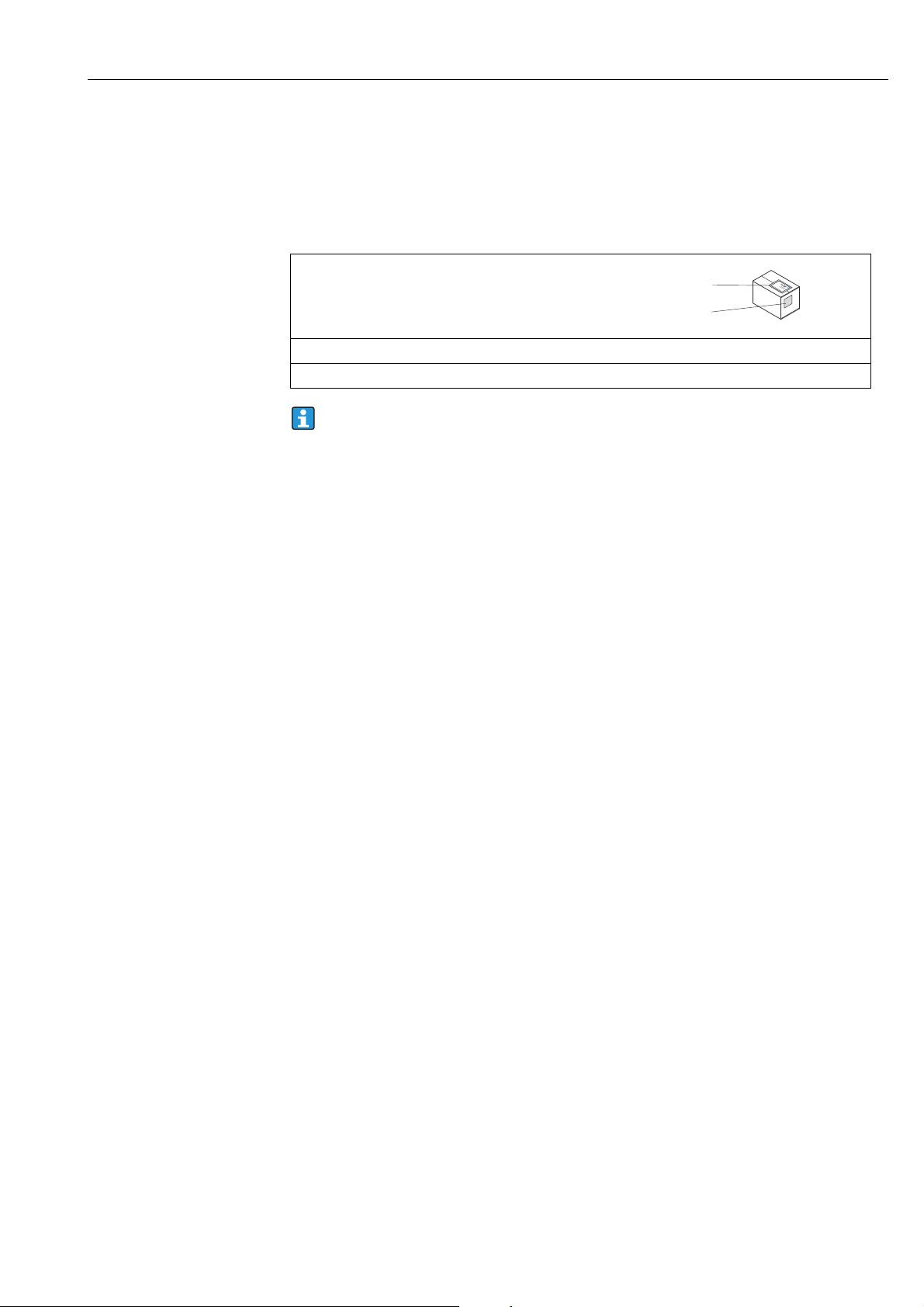
4.1 Incoming acceptance
Is the order code on the delivery note (1) identical to the order code
on the product sticker (2)?
A0027449
Is the measuring device undamaged?
Do the nameplate data match the ordering information on the delivery note?
If one of the conditions is not satisfied, contact your Endress+Hauser Sales Center.
4.2 Product identification
The following options are available for identification of the measuring device:
• Nameplate specifications
• Order code with breakdown of the device features on the delivery note.
• Enter the serial number indicated on the nameplate in W@M Device Viewer
(www.endress.com/deviceviewer): all the information about the measuring device is
displayed.
• Enter the serial number indicated on the nameplate into the Endress+Hauser Operations
App or scan the 2-D matrix code (QR code) on the nameplate with the Endress+Hauser
Operations App: all the information about the measuring device is displayed.
For an overview of the scope of the Technical Documentation provided, refer to the
following:
• "Additional standard device documentation" section ( 7) and
"Supplementary device-dependent documentation" section ( 7)
• W@M Device Viewer: serial number indicated on the nameplate
(www.endress.com/deviceviewer)
• The Endress+Hauser Operations App: enter the serial number indicated on the nameplate
or scan the 2-D matrix code (QR code) provided on the nameplate.
Endress+Hauser 11
Page 12
Incoming acceptance and product identification Nanomass Gas Density
1
Order code:
Ext. ord. cd.:
Ser. no.:
Date:
FW: Dev.Rev.:
p max:
Tm/Ta:
Density range:
Suitable medium:
i
CRN no.:
2
3
4
5
6
7
8
9
10
11
12
14 15 19 20
21
22
23
161317
18
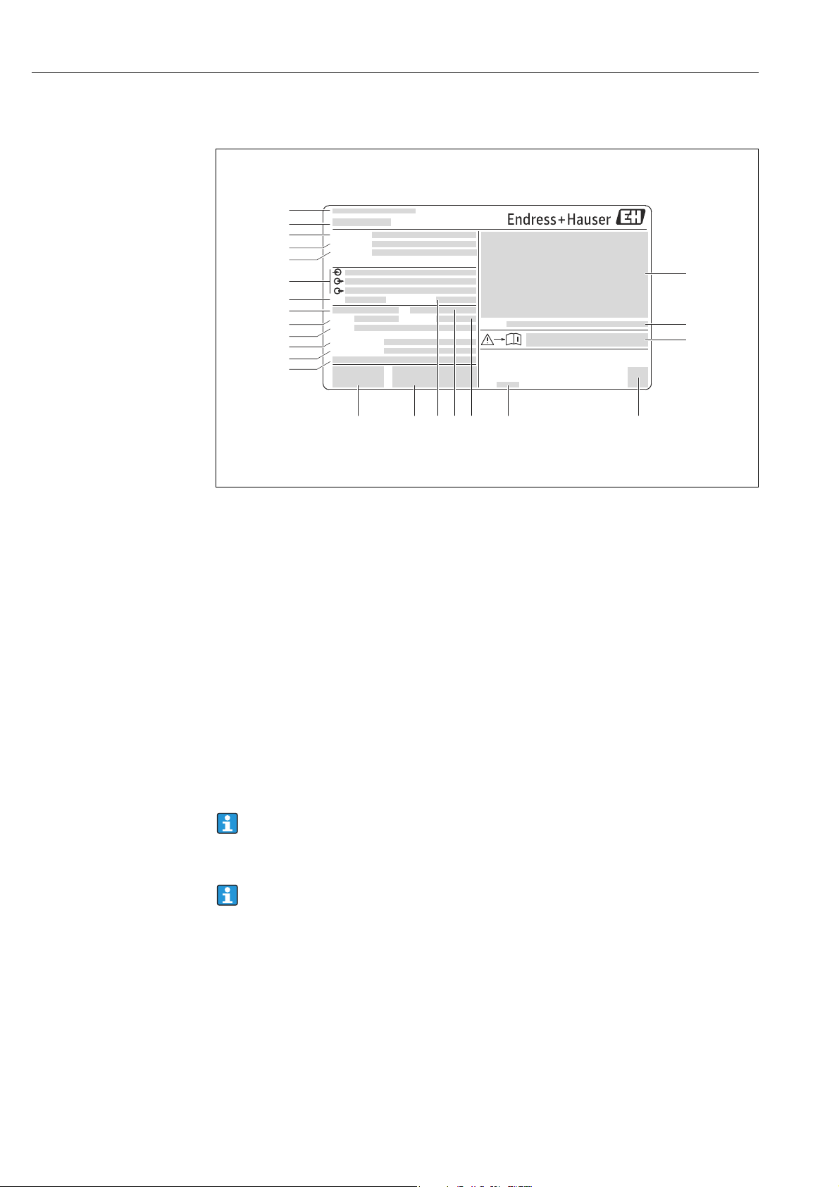
4.2.1 Nameplate
Fig. 2: Example of a nameplate
1 Place of manufacture
2 Name of the measuring device
3Order code
4 Serial number (ser. no.)
5 Extended order code (ext. ord. co.)
6 Electrical connection data, e.g. available inputs and outputs, supply voltage
7 Firmware version (FW)
8 Nominal diameter of the micro-channel
9 Maximum permitted system pressure
10 Permitted ambient temperature range (T
11 Permitted medium density range
12 Permitted media
13 Additional information on the device version: special product
14 CE mark, C-tick
15 Additional information on the device version: certificates, approvals
16 Device version (Dev.Rev.)
17 Nominal diameter of the process connection
18 IP protection class
19 Date of manufacture: year-month
20 2-D matrix code
21 Document number of safety-related supplementary documentation
22 Approval information for CRN
23 Approval information for explosion protection
) and medium temperature range (Tm)
a
Order code
The measuring device is reordered using the order code.
A0026851
Extended order code
• The device type (product root) and basic specifications (mandatory features) are always
12 Endress+Hauser
listed.
• With regard to optional specifications (optional features), only the safety and approvalrelated specifications are listed (e.g. LD). If other optional specifications have also been
ordered, they are indicated by the placeholder symbol "#" (e.g. #LD#).
• If ordered optional specifications do not include any safety and approval-related
specifications, they are indicated by the placeholder symbol (+).
(e.g. DCEBN7-AAACAA01AA11+).
Page 13

Nanomass Gas Density Incoming acceptance and product identification
4.2.2 Symbols on measuring device
Symbol Meaning
WARNING
#
A0011199
A0011194
This symbol alerts you to a life-threatening situation. Failure to avoid this situation
can result in serious or fatal injury.
Protective ground connection
A terminal which must be connected to ground prior to establishing any other
connections.
Reference to documentation
Refers to the corresponding measuring device documentation.
Endress+Hauser 13
Page 14

Storage, transportation, disposal of packaging Nanomass Gas Density
5 Storage, transportation, disposal of packaging
5.1 Storage conditions
Observe the following notes for storage:
• Store in the original packaging to ensure protection from shock.
• Do not remove protection caps mounted on connections.
They prevent any dirt from entering the micro-electro mechanical system (MEMS).
• Protect from direct sunlight to avoid unacceptably high surface temperatures.
• Select a storage location where moisture cannot collect in the measuring device as fungus
and bacteria infestation can damage the MEMS.
• Store in a dry and dust-free place.
• Do not store outdoors.
• Storage temperature 68.
5.2 Transporting the product
Observe the following during transport:
• Transport the measuring device to the measuring point in the original packaging.
• Do not remove protection caps mounted on connections. They prevent contamination of
the MEMS.
• Observe the transport instructions on the adhesive label on the packaging.
5.3 Disposal of packaging
All packaging materials are environmentally friendly and 100% recyclable:
• Measuring device secondary packaging:
– Polymer stretch wrap
–PE foam
• Protection caps on process connections: polymer LDPE
• Packaging: box in accordance with European Packaging Directive 94/62EC;
recyclability is confirmed by the affixed recycling symbol.
• Carrying and mounting hardware:
– Disposable plastic pallet
– Plastic straps
– Plastic adhesive strips
• Dunnage: paper cushion
14 Endress+Hauser
Page 15

Nanomass Gas Density Installation
6Installation
6.1 Installation conditions
No special measures such as supports are necessary. External forces are absorbed by the
construction of the device.
6.1.1 Mounting position
Mounting location
The measuring device is usually installed in a bypass line. If flow rates are low, the device can
also be installed in the main pipe.
Installation in a bypass line is recommended in the following cases:
• Flow rate >1 l/min (0.26 gal/min.)
• Pipeline diameter >6 mm (0.24 in)
Orientation
The orientation of the device does not affect the measuring accuracy.
Flow direction
The flow direction does not affect the measuring accuracy.
Inlet and outlet runs
Inlet and outlet runs do not affect the measuring accuracy.
6.1.2 Requirements from environment and process
Ambient temperature range
Non-Ex version –20 to +60 °C (–4 to +140 °F)
Ex ia IIC T4 version –20 to +60 °C (–4 to +140 °F)
• If operating via USB port: operating temperature is limited to 0 to 60 °C (32 to 140 °F).
• If operating outdoors: avoid direct sunlight, particularly in warm climatic regions.
System pressure
Permitted absolute system
pressure
Max. 20 bar (290 psi)
The relative accuracy of the density measurement increases with increasing system
pressure.
Filter
To prevent the micro-channel from clogging, it is advisable to install a filter upstream from
the measuring device. The filter is included in the delivery.
• Recommended filter pore size: 15 m
Endress+Hauser 15
Page 16

Installation Nanomass Gas Density
1
2
2
34
ΔP < 0.1 bar (1.45 psi)
P2 < P1
P1 < 20 bar (290 psi)
Thermal insulation
Due to a low thermal capacity of the medium, the medium temperature can be greatly
affected by the ambient temperature through the supply line and the measuring device. The
influence of the ambient temperature on the medium temperature can be reduced by
insulating the supply line.
Vibrations
Due to the high operating frequency of the micro-channel, vibrations (<20 kHz) do not affect
measuring accuracy.
6.1.3 Special mounting instructions
Wall mounting
Use drill holes and M6 screws to secure the filter to a wall or a secure base.
A0026012
Pipe mounting
Use the "pipe mounting kit" accessory to secure to a pipe or post.
Installation in a bypass line
Note the following when installing in a bypass line:
• A pressure drop must be created for the medium to flow through the measuring device.
• The maximum permissible pressure drop of 0.1 bar (1.45 psi) across the measuring device
may not be exceeded.
• The bypass line can be routed to the atmosphere or back to the process pipe.
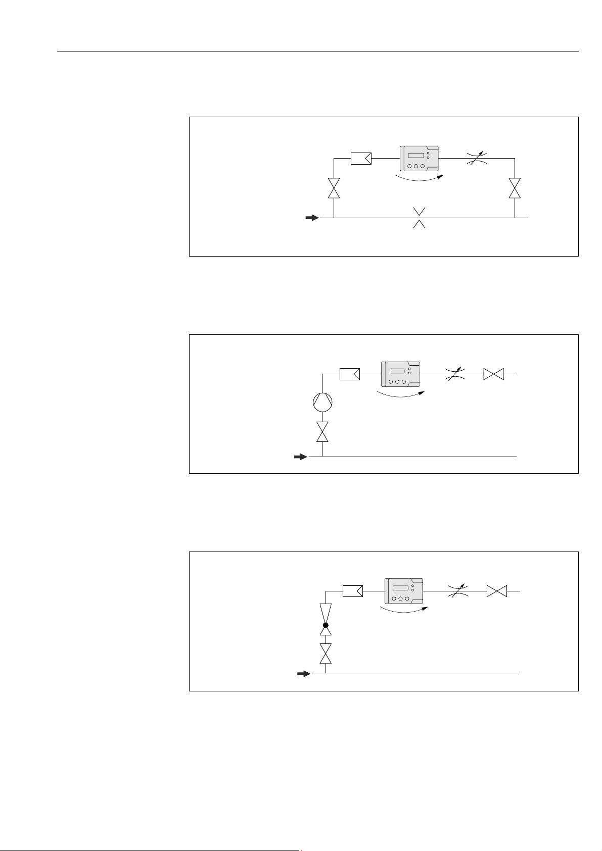
Examples:
• Create necessary pressure drop with throttle (or flow monitor) downstream from the
measuring device.
Fig. 3: 1 = Nanomass; 2 = Valve; 3 = Filter; 4 = Throttle
16 Endress+Hauser
A0026152
Page 17
Nanomass Gas Density Installation
1
22
34
ΔP < 0.1 bar (1.45 psi)
P1 < 20 bar (290 psi)
P2 < P1
5
1
2
2
34
ΔP < 0.1 bar (1.45 psi)
P3 < P2
P1
5
20 bar (290 psi) > P2 > P1
1
2
2
34
ΔP < 0.1 bar (1.45 psi)
P3 < P2
P1 > 20 bar (290 psi)
5
P2 < 20 bar (290 psi) < P1
• Create necessary pressure drop with orifice plate in process pipe and with throttle (or flow
monitor) downstream from the measuring device.
A0026153
Fig. 4: 1 = Nanomass; 2 = Valve; 3 = Filter; 4 = Throttle; 5 = Orifice plate
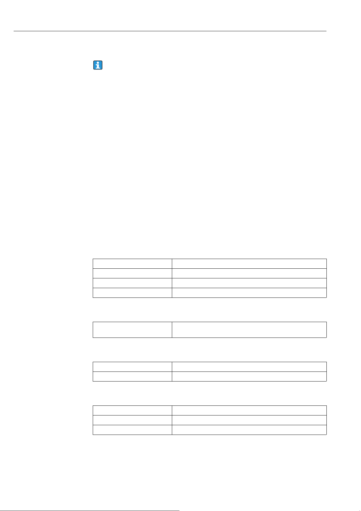
• Create necessary pressure drop with compressor upstream and throttle (or flow monitor)
downstream from the measuring device.
Fig. 5: 1 = Nanomass; 2 = Valve; 3 = Filter; 4 = Throttle; 5 = Compressor
• If process pressure > 20 bar: create necessary pressure drop with pressure reduction valve
upstream and throttle (or flow monitor) downstream from the measuring device.
Fig. 6: 1 = Nanomass; 2 = Valve; 3 = Filter; 4 = Throttle; 5 = Pressure reduction valve
A0026154
A0026155
Endress+Hauser 17
Page 18

Installation Nanomass Gas Density
WARNING
NOTICE
NOTICE
Swagelok pipe fitting
The measuring device and the filter supplied are mounted in the pipe using a ¹⁄" Swagelok
pipe fitting.
1. Cut the pipe at a right-angle and deburr it.
2. Push the pipe into the fitting as far as it will go.
3. Tighten the nut finger-tight.
4. Mark the nut at the 6-o'clock position.
5. Tighten the nut. In doing so, observe the following options:
– When mounting for the first time, tighten with 1 ¹⁄₄ rotations.
– When mounting a second time, tighten with a ¹⁄₄ rotation.
For more information, see the installation instructions for pipe fittings provided by
Swagelok.
Pressure sensor
The measuring device only provides correct measured values when the pressure sensor is
connected. The pressure sensor is already connected when the device is delivered.
Make sure that the pressure sensor is connected correctly.
6.2 Mounting the measuring device
6.2.1 Required tools
For process connections: use an appropriate tool for mounting with Swagelok pipe fittings.
6.2.2 Preparing the measuring device
1. Remove all remaining transport packaging.
2. Remove the protection caps on the inlet and outlet.
6.2.3 Mounting the measuring device
Incorrect device mounting
Burst pipes can cause injury.
Never install the device in the pipe in such a way that it is suspended freely without
additional support.
Mechanical load on the process connections
Pipe forces can affect the vibrations of the micro-channel and thereby impact the accuracy
of measurement.
Avoid high mechanical load on the pipes at process connections.
If mounting on the process pipe, use a wrench to cushion the torque. Do not allow torques
to act on the measuring device.
Blockage of the micro-channel
Install a filter upstream from the measuring device ( 15).
1. To ensure compliance with the maximum flow specifications in the measuring device
and the recommended pressure drop across the measuring device, use a bypass line
with appropriate assemblies where necessary ( 16).
18 Endress+Hauser
Page 19

Nanomass Gas Density Installation
2. Connect the filter to the pipe ( 15) and secure with a Swagelok pipe fitting (
18).
3. Mount the measuring device on a wall or ceiling using drill holes ( 16).
4. Connect the measuring device to the pipe and secure with a Swagelok pipe fitting (
18).
6.3 Post-installation check
Is the device undamaged (visual inspection)?
If assemblies are installed, are they undamaged (visual inspection)?
Does the measuring device conform to the measuring point specifications?
For example:
•Medium 69
• Medium temperature range 69
• Process pressure (refer to the section on "Pressure-temperature ratings" in the "Technical
Information" document )
• Ambient temperature range 15
• Measuring range 65
Are the measuring point identification and labeling correct (visual inspection)?
Is the measuring device adequately protected from precipitation and direct sunlight?
Are the securing screws tightened securely?
Is the pressure sensor connected?
Endress+Hauser 19
Page 20
Electrical connection Nanomass Gas Density
7 Electrical connection
The measuring device does not have an internal circuit breaker. For this reason, assign
the measuring device a switch or power-circuit breaker so that the power supply line can
be easily disconnected from the mains.
7.1 Connection conditions
7.1.1 Required tools
• For cable entries: use an appropriate tool.
• When using stranded cables: use a crimper for wire end ferrule.
7.1.2 Connecting cable requirements
The connecting cables provided by the customer must fulfill the following requirements:
Electrical safety
In accordance with applicable national regulations.
Permitted temperature range
• –40 to 80 °C (–40 to 176 °F)
• Minimum requirement: cable temperature range ambient temperature + 20 K
Power supply cable
Outer diameter 3.5 to 5 mm
Number of cores Min. 2
Cable resistance 77.8 /km at 20 °C
Shielding Single shielding
Signal cable
Shielding A shielded cable is recommended. Observe grounding concept of the
plant.
USB cable
Cable type Mini USB, type B, Buccaneer; standard USB, type A
Cable length Max. 5 m
RS232 cable
Cable type M12, 4-pin; D-Sub, 9-pin
Cable length Max. 5 m
Transmission rate 57600 Bd
20 Endress+Hauser
Page 21

Nanomass Gas Density Electrical connection
2
1
1
4
2
3
2
3
1
4
NOTICE
7.1.3 Pin assignment of connector
Connector for supply voltage
Pin Assignment Coding,
1 L- DC 8 to 30 V A Connector
A0026825
2L+
Connector for signal transmission
4-20 mA connector
Pin Assignment Coding,
1 +/- Current output 1, 4-20 mA
(passive)
A0026826
2 -/+ Current output 1, 4-20 mA
3 +/- Current output 2, 4-20 mA
4 -/+ Current output 2, 4-20 mA
(passive)
(passive)
(passive)
RS232 device socket
Pin Assignment Coding,
1Shield A Socket
2 Txout (transmitted data)
A0026827
3Rxin (received da)
4 Common ground
connector
face
connector
face
A Connector
connector
face
Connector/
socket
Connector/
socket
Connector/
socket
USB device socket
Assignment Connector/socket
Mini-USB, type B, Buccaneer Socket
A0026828
7.1.4 Preparing the measuring device
Remove the protection caps from the connections.
Measuring device not leak tight
If the measuring device is not leak tight, this can impair the operational reliability of the
measuring device.
Only remove the protection caps if connections are used.
Endress+Hauser 21
Page 22

Electrical connection Nanomass Gas Density
WARNING
1
1
2
3
5
5
66
4 4
7.2 Connecting the measuring device
Improper connection can cause serious injury or death
Have electrical connection work carried out by correspondingly trained specialists only.
Observe applicable federal/national installation codes and regulations.
Comply with local workplace safety regulations.
If using in hazardous areas, observe the explosion protection documentation.
A0026017
Fig. 7: Measuring device versions and connection versions
1 Connector for 4-20 mA
2 RS232 interface (optional)
3 USB port (optional)
4Grounding clamp
5 Connector for supply voltage
6 Connector for pressure sensor (connected on delivery)
7.2.1 Connecting the supply voltage cable
The supply voltage can be connected via the supply voltage connection or in an area without
explosion hazards optionally via the USB port. If the supply voltage connection is to be used
for the supply voltage, perform the following steps:
1. Measuring device with USB port: make sure that the measuring device is disconnected
from the USB port.
2. If necessary, strip 10 mm (0.4 in) of the supply voltage cable and cable ends. In the case
of stranded cables, also fit ferrules.
3. Where applicable, connect the cable to the connector for supply voltage in accordance
with the pin assignment 21.
4. Insert the connector into the supply voltage connection of the measuring device and
screw tight.
5. If using in hazardous areas: fit the USB protection cap and tighten securely.
22 Endress+Hauser
Page 23

Nanomass Gas Density Electrical connection
7.2.2 Connecting the signal cables
Signals can be transmitted digitally via a USB port or RS232 interface or by analog
communication via the passive 4-20 mA connection.
Connect the 4-20 mA cable
1. Strip 10 mm (0.4 in) of the cable and cable ends. In the case of stranded cables, also fit
ferrules.
2. Connect the cable to the 4-20 mA connector in accordance with the pin assignment
21.
3. Insert the connector into the 4-20 mA connection of the measuring device and screw
tight.
4. Connect the signal cable to the 12-24 V power supply 24.
Connect the RS232 cable (optional)
1. If necessary, strip 10 mm (0.4 in) of the cable and cable ends. In the case of stranded
cables, also fit ferrules.
2. Where applicable, connect the cable to the RS232 connector in accordance with the pin
assignment 21.
3. Connect the RS232 cable to the RS232 socket of the measuring device and the COM port
(RS232) of the PC and screw tight.
Connect the USB cable (optional)
1. Make sure that the measuring device is disconnected from the supply voltage.
2. Connect the USB cable to the USB port of the measuring device and the USB port of the
PC.
3. Secure the cable to the device with a protection cap and cable clamp.
Endress+Hauser 23
Page 24

Electrical connection Nanomass Gas Density
4...20 mA
421
+
5
4...20 mA
+
6
4
2
+
+
_
3
+
_
3
_
+
_
_
_
7.3 Special connection instructions
7.3.1 Connection examples
Current output 4-20 mA
A0026824
Fig. 8: Connection example for 4-20 mA current output
1 Automation system with current input (e.g. PLC)
2 Cable shield, comply with connecting cable requirements (→ 20)
3 Power supply 12-24 V
4 Analog display unit: observe maximum load (→ 65)
5 Measuring device, current output 1 (pin 1 and 2, protected against reverse polarity)
6 Measuring device, current output 2 (pin 3 and 4, protected against reverse polarity)
7.4 Guaranteeing the degree of protection
The measuring device meets all the requirements of IP65/67 protection.
To guarantee IP65/67 protection, carry out the following steps after the electrical
connection:
For USB port:
1. Check whether the seals of protection caps are clean and inserted correctly.
2. Fit the protection caps and tighten securely.
24 Endress+Hauser
Page 25

Nanomass Gas Density Electrical connection
7.5 Post-connection check
Are cables and the device undamaged (visual inspection)?
Do the cables comply with the requirements ( 20)?
Do the cables have adequate strain relief?
Does the supply voltage match the specifications on the nameplate?
Are all connectors installed and protection caps securely tightened?
Is the pin assignment of the connectors correct?
Depending on the device option and the use of the device: is the USB connector secure?
If supply voltage is provided, is the power LED on the measuring device lit?
Endress+Hauser 25
Page 26

Operating options Nanomass Gas Density
NOTICE
ESC
E
+
-
1
.00145 kg/ccρ= 0
Temp= 23.21°C
2
Power
Error
3
8 Operating options
8.1 Overview of operating options
The measuring device offers users the following operating options:
• Local operation
• "Nanomass Communication" operating tool (via USB port or RS232 interface)
The operating language of the measuring device is English. Other language options are
not supported.
Errors during measurement values transmission
Errors may occur at the current output during the measurement values transmission with
the local operation or the "Nanomass Communication" operating tool.
Complete operation for correct measurement value.
8.2 Access to the measuring device via the local display
8.2.1 Operational display
The operational display is used to display measured variables, parameters, dialog texts and
error messages.
A0027442
Fig. 9: Operational display
1 Measured value display and parameterization view (2-lines)
2 Operating elements
3 LED status indicator
Measured value display
A measured variable is displayed on every line. A maximum of four measured variables in
total can be displayed in multiplex mode. In multiplex mode, the measured variables
alternate on the screen every 5 seconds.
Measured variables
Abbreviation Description
ρ Density
ρr Reference density
26 Endress+Hauser
Temp Temperature
Conc Concentration
Press Pressure
Page 27

Nanomass Gas Density Operating options
1
Measure variables
User interface
2
1
System units
Special units
2
1
Density
g/cc
2
-
+
E
E
+
E
-
+
+
+
-
+
The number and display format of the measured values can be configured in the "User
interface" "Assign" menu.
Parameterization views
The user is in the operational display mode: press Enter to enter the parameterization
mode.
Menu Submenu Parameter
1 2Selected menu item
Next menu item
Operating elements
Key Description
Minus key
A0027444
A0027443
A0027445
In a menu or submenu
Navigate between the menus or submenus
In a parameter
Change a parameter value
Plus key
In a menu or submenu
Navigate between the menus or submenus
In a parameter
Change the parameter value
Enter key
In a menu or submenu
Call a submenu or parameter
In a parameter
Confirm an entry or navigate to the next parameter
A0027439
1 2Selected submenu item
Next submenu item
A0027446
A0027441
1 2Parameter name
Parameter value
Back/Forwards key combination (press keys simultaneously)
In a parameter
Navigate within a parameter value to the next or previous number or digit.
A0027447
Escape key combination (press keys simultaneously)
In a menu
A0027440
Exit the parameterization view and go to the measured value display
In a submenu
Exit the submenu and go to the menu
In a parameter
Exit the parameter and go to the submenu
LED status indicators
For a description, see "Diagnostic information via light emitting diodes" 55.
Endress+Hauser 27
Page 28

Operating options Nanomass Gas Density
8.2.2 Functions
Function Operation
Display measured values Once the measuring device has been connected to
Enter parameterization The user is in the operational display mode.
the supply voltage and the measuring device is
ready for operation, the measured values appear
on the operational display.
Press Enter.
Disable write protection via access code Parameterization is protected by an access code.
This code cannot be configured.
Enter the access code 0074 using the plus and
minus keys. Press Enter to confirm each digit.
Navigate between the menus or submenus The user is in the parameterization view in a
menu or submenu.
Press the Plus or Minus key.
Call submenus or parameters The user is in the parameterization view in a
menu or submenu.
Press Enter.
Change parameter values The user has called up a parameter.
Press the Plus or Minus key.
Navigate within the parameter value to the next
number or digit
The user has called up a parameter and makes
changes to a parameter value.
Press the Plus and Enter key or the Minus and
Enter key simultaneously.
Confirm entries The user has called up a parameter and makes
changes to a parameter value.
Press Enter.
Navigate to the next parameter The user has called up a parameter.
Press Enter.
Return to the previous menu or submenu
Press the Plus and Minus key simultaneously.
8.3 Access to the measuring device via the "Nanomass Communication" operating tool
8.3.1 Function scope
The measuring device can be operated and configured via the "Nanomass Communication"
operating tool. The parameter structure is the same as with the local display ( 75). In
addition to the measured values and the parameters, status information on the measuring
device is also displayed and allows the user to monitor the status of the device. Furthermore
the measuring device data can be managed and visualized and basic device parameters (e.g.
calibration factors or device clock) can be configured.
8.3.2 Prerequisites
Hardware
Connecting cable Depends on the device interface:
• USB cable: mini USB, type B, Buccaneer; standard USB, type A or
• RS232 cable: M12, 4-pin, gold contact; D-Sub, 9-pin
28 Endress+Hauser
Page 29

Nanomass Gas Density Operating options
NOTICE
Computer Depends on the device interface:
•USB port or
•RS232 interface
Disk drives (in the case of installation the "Nanomass Communication" operating
tool via CD-ROM):
•CD-ROM drive
Computer software
Recommended
operating system
Drivers •USB driver
Computer
configuration
PC:
• Windows 8.1 (32bit or 64bit)
• Windows 7 (32bit or 64bit)
•Windows XP
For installing on Windows XP, Windows 7 and Windows 8.1 administrator
rights are required.
The following components must be installed on the PC to be able to install the
"Nanomass Communication" operating tool. If the components are not already
installed, they will be installed automatically when the setup file is run.
• National Instruments VISA Runtime, Version 5.4 or higher
• For USB port: virtual serial interface according to RS232 (virtual com port)
8.3.3 Installing the "Nanomass Communication" operating tool
Upgrading from an earlier version
If an earlier version of the tool is installed, installing a new version can cause problems.
Uninstall the earlier version before installing the new "Nanomass Communication"
operating tool.
Installing the "Nanomass Communication" operating tool
1. Close all applications.
2. Insert the CD-ROM supplied in the drive.
3. Start the installation by double clicking on "setup.exe" in the CD directory "software/
Nanomass Communication".
4. Follow the instructions in the installation window.
8.3.4 Connecting the measuring device to the PC
For information on connecting the device via an RS232 or USB cable 23.
8.3.5 Establishing a connection
The "Nanomass Communication" operating tool automatically detects the measuring device
connected to the PC. Several devices can be connected simultaneously. Only one measuring
device can be selected in the operating tool, however.
1. Start Nanomass Communication.
The PC assigns the COM port automatically for the connected measuring device.
2. In the "COM-Port" selection box, select the COM port assigned by the PC for the
connected measuring device.
Endress+Hauser 29
Page 30

Operating options Nanomass Gas Density
First connection of the device
If the device is connected the first time on the computer, it will incorrectly recognized.
In case of first device connection install USB driver.
Install USB driver:
1. Depending on the version, connect the device to your computer via the USB- or the
RS232-interface.
2. Open the Device Manager.
3. Update the driver software by right click on the device.
4. Select the manual search and the installation of the driver software in the installation
window. The driver software is located in the directory "drivers/USB_driver_F".
5. Follow the instructions in the following installation windows.
No COM port is displayed
1. Select "Refresh" in the "COM-Port" selection box.
The PC updates the picklist.
2. In the "COM-Port" selection box, select the COM port assigned by the PC for the
connected measuring device.
30 Endress+Hauser
Page 31

Nanomass Gas Density Operating options
123 4 5
8.3.6 User interface
Fig. 10: User interface
1 Exit Nanomass Communication
2 Nanomass Communication software version
3 Establish a connection
4 Device configuration and device functions
5 Measured value display and status indication
Establishing a connection
Selection/display Description
COM port Communication interface
Select the communication interface for communicating with the measuring device. The
list displayed contains all the COM ports available. A "Refresh" function is also provided
to update the list.
Device type Device type
Displays the type of device that is connected ("Nanomass Gas Density").
A0027438
Endress+Hauser 31
Page 32

Operating options Nanomass Gas Density
Device configuration and device functions
Function area Description
Parameter Parameter
Access to the device's operating menu structure; same as local display:
• Configuration of parameters
Real-time
measuring data
Measuring data
retrieval
Device settings Device settings
Real-time measuring data
Access to current measured values:
• Graphic display of current measured values
• Recording of current measured values (in text file)
Measuring data retrieval
Access to the internal data memory:
• Settings for saving measured values
• Export saved measured values (to text file)
Access to device information and device settings:
• Display device information
• Configure the communication port (COM port)
• Configure the display delay
• Configure the device clock
• Configure the calibration parameters
•Service functions (protected by a code)
To access the "Device settings" function area, you must enter the access code 0074
in the "Access code for technician mode" field and then press "OK" to confirm.
Measured value display
The measuring variables listed below are displayed along with their unit in the measured
value display area. The display format can be changed via the parameter settings. A red
signal to the right of the measured value indicates whether this value is being saved to a file.
Measuring variables
Measuring variable Description
Density Density
Displays the measured density.
Reference Density Reference density
Displays the calculated reference density. The measuring variable is only displayed if
the "Fixed" parameter value is selected in the "Density function" parameter.
Temperature Temperature
Concentration Concentration
Pressure Pressure
Displays the medium temperature measured during density measurement.
Displays the calculated concentration of a substance. The measuring variable is only
displayed if the "Concentration Measurement" application package is used and the
"Flexible" parameter value is selected in the "Density function" parameter.
Displays the pressure measured by the sensor during density measurement.
32 Endress+Hauser
Page 33

Nanomass Gas Density Operating options
1
2
3
8.3.7 Parameter
Users can access the operating menu structure of the device in the "Parameter" function area.
This menu structure can also be called via local operation.
Screen layout
Fig. 11: Parameter
1 Navigation area
2 Displays the configured parameter value
3 Configuration area
A0027435
Choosing parameters
It is not possible to directly select an individual parameter in the navigation area.
To select a parameter, select the menu or submenu in question e.g. "Measuring variables"
or "System units".
Parameters pertaining to the menu are displayed in the configuration area to the
right of the navigation area.
Changing parameter values
Enter or select the parameter value in the input box.
The measuring device adopts the new parameter value and "Refreshing" is displayed
on the screen.
Endress+Hauser 33
Page 34

System integration Nanomass Gas Density
9 System integration
9.1 Overview of device description files
9.1.1 Current version data for the device
Firmware version • On the title page of the Operating instructions
Release date of firmware version 31.08.2015
Device type ID • In Nanomass Communication: Header "Device type"
Device version On the nameplate ( 12)
• On the nameplate ( 12)
• In Nanomass Communication: function area "Device settings"
"Device information" "Firmware Version"
• On the local display during device start-up.
• On the local display during device start-up.
9.1.2 Operating tools
Operating tools via serial interface Sources for obtaining device descriptions
Nanomass Communication • www.endress.com Download Area
• CD–ROM (contact Endress+Hauser)
9.2 Measured variables via serial interface
9.2.1 General settings for the serial interface
Baud rate 19200
Data bits 8
Stop bits 1
Parity bit None (0)
FlowControl None (0)
Transmission mode By packet (char = 8 bit or 1 byte)
34 Endress+Hauser
Page 35

Nanomass Gas Density System integration
@!000820.55 !00050.00062@!00060.00000@!00091.02@!@
1
23123123123
1
9.2.2 Data structure and commands
The commands which can be used to read measured variables and device information out of
the measuring device are listed below. The data are transmitted in packets. The data are
divided into seven packets. Only packet 5 is variable and can be used. For data interrogation,
the bytes must be specified in hexadecimal format.
Packet Byte (hex) Description String output
String
name
10x01No access possible --
20x00No access possible --
30x00No access possible --
40x00No access possible --
5 0x05 Device information pcb No function
mtf No function
den No function
de No function
fid No function
Description
pip No function
cus Tag name
(defined by customer)
ser Serial number
0x08 Measured data 0008 Temperature in °C
0005 Density in kg/m
0006 Reference density
0011 Concentration
0009 Pressure in bar absolute
60x02No access possible --
70x03No access possible --
3
Example
String entry to call up measured data: 0x01 0x00 0x00 0x00 0x08 0x02 0x03.
The device returns the following data. Please note that the string values used are only
sample values:
Fig. 12: String entry
1Separator
2String name
3 String value
Endress+Hauser 35
A0027448
Page 36

Commissioning Nanomass Gas Density
10 Commissioning
10.1 Installation and function check
Before commissioning the device, make sure that the post-installation and post-connection
checks have been performed.
• "Post-installation check" checklist 19.
• "Post-connection check" checklist 25.
10.2 Switching on the measuring device
After a successful function check, switch on the measuring device. If power is supplied via
the USB port, the measuring device starts automatically as soon as the USB cable is
connected.
After a successful startup, the local display switches automatically from the startup display
to the operational display.
If nothing appears on the local display or an error message is displayed, refer to the
section on "Diagnostics and troubleshooting" 54.
10.3 Setting the operating language
The operating language of the measuring device is English. Other language options are not
available.
10.4 Configuring the measuring device
An overview of all the device parameters and a description of the parameters is provided
in the appendix 75.
10.4.1 Defining the tag name
The tag name must be defined via the "Nanomass Communication" operating tool.
Navigation
Function area "Device settings" "Device information" "Tag name"
To access the "Device settings" function area, you must enter the access code 0074 in the
"Access code for technician mode" window and then press "OK" to confirm.
Defining the tag name
1. Call up the "Device settings" function area.
2. Enter the new tag name under "Tag name" in the "Device information" area.
3. Click "Send" to confirm the name.
The message "Tag name changed" appears.
The name is saved in the device.
4. Click "OK" to confirm the message.
10.4.2 Setting the serial port delay time
The delay time for sending and receiving data via the serial port must be defined via the
"Nanomass Communication" operating tool.
36 Endress+Hauser
Page 37

Nanomass Gas Density Commissioning
Navigation
Function area "Device settings" "COM-Port "Data retrieval delay"
To access the "Device settings" function area, you must enter the access code 0074 in the
"Access code for technician mode" field and then press "OK" to confirm.
Setting the delay time
1. Call up the "Device settings" function area.
2. Under "Data retrieval delay" in the "COM-Port" area, enter a delay time of between 200
and 500 ms for the serial port.
The delay time is saved in the device.
10.4.3 Setting the sampling rate
The frequency at which data are saved in the internal data memory must be defined via the
"Nanomass Communication" operating tool.
Navigation
Function area "Device settings" "Internal data logger" "Sampling rate"
To access the "Device settings" function area, you must enter the access code 0074 in the
"Access code for technician mode" field and then press "OK" to confirm.
Setting the sampling rate
1. Call up the "Device settings" function area.
2. Under "Sampling rate" in the "Internal data logger" section, enter the sampling rate at
which data are saved in the internal data memory. The sampling rate can be between
1 and 3600 seconds.
3. Click the "Set sampling rate" button to confirm the sampling rate.
The sampling rate is saved in the device.
10.4.4 Setting the date and time
The date and time in the measuring device must be defined via the "Nanomass
Communication" operating tool.
Navigation
Function area "Device settings" "Device settings"
To access the "Device settings" function area, you must enter the access code 0074 in the
"Access code for technician mode" field and then press "OK" to confirm.
Setting the date and time
1. Call up the "Device settings" function area.
2. Click the "Set clock" button in the "Device settings" area.
An input box and a calendar function appear.
3. Enter the time and date, or select them from the calendar, and click the "Send date and
time" button to confirm your settings.
The message "Data and time changed" appears.
The date and time are saved in the measuring device.
4. Click "OK" to confirm the message.
Endress+Hauser 37
Page 38

Commissioning Nanomass Gas Density
10.4.5 Configuring the current output
Various parameters are used to configure the current output. In addition, there are
differences depending on which current output is being configured.
Navigation
1. Menu "Measuring variables" "System units"
2. Menu "Output 4-20 mA" "Output channel 1" and "Output channel 2"
3. Menu "Output 4-20 mA" "Response channel 1/2"
4. Menu "Supervision" "Assign error prompt for channel 2"
Parameter overview with brief description
Menu "Measuring variables" → "System units"
Parameter Procedure Selection/input Factory setting
Density Select the unit for density.
Result
The selected unit applies for:
• The "Density" process variable
• The "4mA Ch1" parameter
• The "20mA Ch1" parameter
• The "4mA Ch2" parameter
• The "20mA Ch2" parameter
Note
If the unit is changed, configured current
output values are automatically adapted
to the new unit.
Specific Gravity = measured density/
density of air;
Molecular weight = average molar mass
according to the ideal gas law
Reference density Select the unit for reference density.
Result
The selected unit applies for: the
"Reference Density" process variable
Note
If the unit is changed, configured current
output values are automatically adapted
to the new unit.
Temperature Select the unit for temperature.
Result
The selected unit applies for:
• The "Temperature" process variable
• The "4mA Ch1" parameter
• The "20mA Ch1" parameter
• The "4mA Ch2" parameter
• The "20mA Ch2" parameter
Note
If the unit is changed, configured current
output values are automatically adapted
to the new unit.
•g/cm³
•g/cc
•kg/L
•kg/m³
•Lb/ft³
•Lb/gal
• Unit defined under "Text arb.
density"
•Specific gravity
•Molecular weight
•g/cm³
•g/cc
•kg/L
•kg/m³
•Lb/ft³
•Lb/gal
•°C
•K
•°F
•°R
kg/m³
kg/m³
Country-specific:
•°C
•°F
38 Endress+Hauser
Page 39

Nanomass Gas Density Commissioning
Parameter Procedure Selection/input Factory setting
Pressure Select the unit for pressure.
Result
The selected unit applies for:
• The "Pressure" process variable
• The "4mA Ch1" parameter
• The "20mA Ch1" parameter
• The "4mA Ch2" parameter
• The "20mA Ch2" parameter
Note
If the unit is changed, configured current
output values are automatically adapted
to the new unit.
• bar absolute
•bar gauge
• psi absolute
• psi gauge
•kPa absolute
•kPa gauge
Country-specific:
•kPa absolute
• psi absolute
Menu "Output 4-20mA" → "Output channel 1
Parameter Description Selection/input Factory setting
Assign Select process variable for current output 1.•Off
•Density
•Ref. density
• Concentration (optional)
•Temperature
• Pressure
Span Select current span for current output 1. • Namur 4-20mA
• Non Namur 4-20mA
4mA Ch1 Enter the lower limit for 4 mA current. Decimal. 0 (kg/m
20mA Ch1 Enter the upper limit for 20 mA current. Decimal. 1 (kg/m
Density
Non Namur 4-20mA
3
)
3
)
Menu "Output 4-20mA" → "Output channel 2"
Parameter Description Selection/input Factory setting
Assign Select process variable for current output 2.•Off
•Density
•Ref. density
• Concentration (optional)
•Temperature
• Pressure
Span Select current span for current output 2. • Namur 4-20mA
• Non Namur 4-20mA
4mA Ch2 Enter the lower limit for 4 mA current. Decimal. 0 (°C)
20mA Ch2 Enter the upper limit for 20 mA current. Decimal. 20 (°C)
Temperature
Non Namur 4-20mA
Menu "Output 4-20mA" → "Response channel 1/2"
Parameter Description Selection/input Factory setting
Failsafe mode channel 1 Specify the output behavior of current
output 1 in the event of a device alarm.
Note
In the event of a breakdown of the power
supply the value of the current output is
<1 mA. The failure mode in accordance
with NAMUR Recommendation NE 43 is
ensured.
• Min current
•Max current
•Hold value
•Actual value
Min current
Endress+Hauser 39
Page 40

Commissioning Nanomass Gas Density
Parameter Description Selection/input Factory setting
Failsafe mode channel 2 Specify the output behavior of current
output 2 in the event of a device alarm.
Note
In the event of a breakdown of the power
supply the value of the current output is
<1 mA. The failure mode in accordance
with NAMUR Recommendation NE 43 is
ensured.
•Min current
• Max current
•Hold value
•Actual value
Min current
Menu "Supervision" → "Assign error prompt for channel 2"
Parameter Description Selection/input Factory setting
Tube not oscillating Select whether an error message should
be displayed at current output 2 if the
measuring channel is not oscillating or is
oscillating in the wrong frequency range.
Density range Select whether an error message should
be displayed at current output 2 if the
density value is outside the permitted
range.
•On
•Off
•On
•Off
Off
Off
10.4.6 Configuring the local display
Various parameters are used to configure the local display.
Navigation
1. Menu "User interface" "Assign" "Top line display"
2. Menu "User interface" "Assign" "Top line display multiplex"
3. Menu "User interface" "Assign" "Bottom line display"
4. Menu "User interface" "Assign" "Bottom line display multiplex"
Parameter overview with brief description
Menu "User interface" → "Assign" → "Top line display"
Parameter Description Selection/input Factory setting
Top line display Select the measured value that is shown
on the top line of the local display.
•Off
•Density
• Concentration (optional)
•Ref. density
• Temperature
• Pressure
Density
Menu "User interface" → "Assign" → "Top line display multiplex"
Parameter Description Selection/input Factory setting
Top line display multiplex Select the measured value that is shown
on the top line of the local display when
the display changes.
•Off
•Density
• Concentration (optional)
•Ref. density
• Temperature
• Pressure
Off
40 Endress+Hauser
Page 41

Nanomass Gas Density Commissioning
Menu "User interface" → "Assign" → "Bottom line display"
Parameter Description Selection/input Factory setting
Bottom line display Select the measured value that is shown
on the second line of the local display.
•Off
•Density
• Concentration (optional)
•Ref. density
•Temperature
• Pressure
Temperature
Menu "User Interface" → "Assign" → "Bottom line display multiplex""
Parameter Description Selection/input Factory setting
Bottom line display multiplex Select the measured value that is shown
on the second line of the local display
when the display changes.
•Off
•Density
• Concentration (optional)
• Ref. density
• Temperature
• Pressure
Pressure
10.4.7 Configuring the output behavior
Various parameters are used to configure the output behavior.
Navigation
1. Menu "Output 4-20mA" "Response channel 1/2" "Time constant output"
2. Menu "Basic function" "System parameter" "Time constant input"
Parameter overview with brief description
Menu "Output 4-20mA" → "Response channel 1/2" → "Time constant output"
Parameter Description Selection/input Factory setting
Time constant output Set the response time of the output signal
to variations in the measured value.
Menu "Basic function" → "System parameter" → "Time constant input"
Parameter Description Selection/input Factory setting
Time constant input Set the response time of the local display
to variations in the measured value.
Positive integer 0 to 120 s 0 s
Positive integer 0 to 120 s 0 s
10.5 Advanced settings
The measuring device supports the entry of user-defined units. Furthermore, it is possible to
configure reference density measurement and concentration measurement as well as
density adjustment.
10.5.1 Entering user-defined density units
A user-defined unit can be entered for the "Density" measuring variable in the "Special Units"
menu. The unit is then available for selection in the "Density" parameter in the menu
"Measuring variables" "System units".
Endress+Hauser 41
Page 42

Commissioning Nanomass Gas Density
Navigation
Menu "Measuring variables" "Special units"
Parameter overview with brief description
Menu "Measuring variables" → "Special units"
Parameter Description Selection/input Factory setting
Text arb. density (4 char.) Enter the text string for the arbitrary
density unit. The unit is then available
for selection in the "Density" parameter in
the "System unit" menu.
Factor arbitrary density Enter the quantity factor for the arbitrary
density unit. The factor converts the
original measured value into the
arbitrary unit.
XXXX (max. 4 characters) "___" (no text)
6-digit floating point number and
a 1-digit exponent
1.00000E+0
10.5.2 Configuring reference density measurement
Settings for calculating the reference density can be made in the "Special Function" menu.
Navigation
Menu "Special function" "Density function"
Parameter overview with brief description
Menu "Special function" → "Density function"
Parameter Description Selection/input Factory setting
Density type Select the density function for calculating
special density values or the percentage
of components in binary mixtures.
Reference pressure Enter the reference pressure for
calculating the reference density.
Reference temperature Enter the reference temperature for
calculating the reference density.
•Fixed Off
Decimal number with sign 14.7 psi a
Decimal number with sign 20 °C
10.5.3 Configuring the concentration measurement
Information on concentration measurement 44
10.5.4 Performing density adjustment with medium
A density adjustment can be performed under process conditions to achieve optimum
accuracy. The density adjustment must be performed using the "Nanomass Communication"
operating tool.
Navigation
Function area "Device settings" Menu "Calibrate density" "Single point density calibration"
To access the "Device settings" function area, you must enter the access code 0074 in the
"Access code for technician mode" field and then press "OK" to confirm.
42 Endress+Hauser
Page 43

Nanomass Gas Density Commissioning
Performing density adjustment with medium
The measuring device must be filled with the medium to perform density adjustment.
Furthermore, the exact density of the medium at the indicated temperature and
pressure must be known.
1. Call up the "Device settings" function area.
2. In the "Calibrate density" section, click the "Enter actual density" button to enter the
current density.
The "Prompt" window opens.
3. Enter the value of the current density in the "Density" field and click "OK" to confirm.
The message "Are you sure you want to continue?" appears.
4. Click "Yes, calibrate" to perform the density adjustment.
Density adjustment commences.
Density adjustment has failed
If the density adjustment does not go to plan, the default factory density coefficients
can be restored with the "Reset field calibration" function.
1. Call up the "Device settings" function area.
2. In the "Calibrate density" section, click the "Perform reset" button to reset the density
calibration to the factory default setting.
The "Reset field calibration density offset value" message appears on the display.
3. Click "Continue" to continue the reset process.
The density calibration is reset to the factory default.
10.6 Simulation
The "Simulation" function allows users to simulate different process variables and the device
alarm behavior without a real measuring situation.
Navigation
Menu "Output 4-20mA" "Simulation"
Parameter overview with brief description
Menu "Output 4-20mA" → "Simulation"
Parameter Description Selection/input Factory setting
Activate simulation Switch simulation of the current outputs
on and off.
Current value Enter the current value for simulation. 2.00 to 23.00 mA 2.00 mA
•On
•Off
Off
10.7 "Datalog Function" application package
10.7.1 Availability
If the "Datalog Function" application package was ordered for the measuring device ex works,
the function is available when the measuring device is delivered from the factory. The
function is accessed via Nanomass Communication. No particular measures are required to
be able to put the function into operation.
Endress+Hauser 43
Page 44

Commissioning Nanomass Gas Density
Ways to check function availability:
• Using the serial number on the device:
W@M Device viewer order code option EB "Datalog function"
• In the operating menu of Nanomass Communication:
Check, whether the function appears in Nanomass Communication. If it is possible to open
the "Measuring data retrieval" function area, the function is activated.
If the function cannot be accessed, the application package was not selected when the device
was ordered. It is possible to subsequently activate the function.
10.7.2 Activation
For activation, a conversion kit from Endress+Hauser is required. Among other things, this
kit contains an activation code which must be entered via Nanomass Communication to
activate the "Concentration Measurement" function.
The activation function is available under "Device Settings" "Service mode" "Activate
software options". Once activated the "Datalog function" application package is permanently
available in the measuring device.
To access the "Device settings" function area, you must enter the access code 0074 in the
"Access code for technician mode" field and then press "OK" to confirm. To be able to
access the functions of the "Service mode", the code 4685 for the service mode must be
entered.
10.7.3 General information
The "Datalog function" application package can only be accessed via Nanomass
Communication. After activating the application package, the measuring data that are saved
in the internal data memory can be retrieved in the "Measuring data retrieval" function area.
This also includes the saving of measuring data to a text file that can be imported into a
database. If the "Datalog function" application package was not activated, the "Measuring
data retrieval" function area is not accessable.
10.8 "Concentration Measurement" application package
10.8.1 Availability
If the "Concentration Measurement" application package was ordered for the measuring
device ex works, the function is available when the measuring device is delivered from the
factory. The function is accessed via the measuring device local display or via Nanomass
Communication. No particular measures are required to be able to put the function into
operation.
Ways to check function availability in the measuring device:
• Using the serial number:
W@M Device viewer order code option EC "Concentration"
• In the operating menu:
Check whether the function appears in the operating menu: menu "Special function"
"Density function" "Density type". If the "Flexible" option appears the function is activated.
If the function cannot be accessed in the measuring device, the application package was not
selected when the device was ordered. It is possible to subsequently activate the function.
10.8.2 Activation
For activation, a conversion kit from Endress+Hauser is required. Among other things, this
kit contains an activation code which must be entered via Nanomass Communication to
activate the "Concentration Measurement" function.
44 Endress+Hauser
Page 45

Nanomass Gas Density Commissioning
The activation function is available under "Device Settings" "Service mode" "Activate
software options". Once activated the "Concentration Measurement" application package is
permanently available in the measuring device.
To access the "Device settings" function area, you must enter the access code 0074 in the
"Access code for technician mode" field and then press "OK" to confirm. To be able to
access the functions of the "Service mode", the code 4685 for the service mode must be
entered.
10.8.3 General principles
Once the "Concentration Measurement" application package is activated, the measuring
device can output the concentration of a binary gas mixture. The concentration indicates the
quantity of a pure substance that is in a gas mixture. The density, pressure and temperature
measuring variables make it possible to calculate the concentration of a fluid using
thermodynamic models. If a gas mixture consists of two substances (e.g. methane and
carbon dioxide), the measuring device can calculate the concentration of one of the
substances (e.g. methane or carbon dioxide) and display this information.
10.8.4 Determining the coefficients
Your Endress+Hauser Sales Center can provide you with the coefficients that must be saved
in the measuring device to calculate the concentration. The following information is needed
to determine the coefficients:
• Composition (concentration range) of the binary gas mixture to be measured
• Temperature range in which the gas mixture is measured
• Pressure range in which the gas mixture is measured
The smaller the selected range of concentration, temperature and pressure, the better the
approximation of the coefficients and therefore the better the accuracy. The accuracy also
depends on the difference in density between the two substances in the gas mixture. The
bigger the difference in density, the more accurate the measured values. The measuring
device cannot calculate binary gas mixtures where both substances have the same density
(e.g. nitrogen and carbon monoxide).
10.8.5 Configuring the concentration
Settings for calculating a concentration can be made in the "Special Function" menu.
Navigation
1. Menu "Measuring variables "Special units"
2. Menu "Special function" "Density function"
Parameter overview with brief description
Menu "Measuring variables" → "Special units"
Parameter Description Selection/input Factory setting
Text arb. concentration (4 char.) Enter the text string for the arbitrary
concentration unit. The unit is then
available for selection as "Other 3D" in the
"Concentration unit" parameter in the
"Density function" menu.
Factor arbitrary concentration Enter the quantity factor for the arbitrary
concentration unit. The factor changes
the original measured value from the
concentration specification.
XXXX (max. 4 characters) "___" (no text)
6-digit floating point number and
a 1-digit exponent
1.00000E+0
Endress+Hauser 45
Page 46

Commissioning Nanomass Gas Density
Menu "Special function" → "Density function"
Parameter Description Selection/input Factory setting
Density type Select the density function for calculating
special density values or the percentage
of components in binary gas mixtures.
Concentration unit Select the unit for calculating the
concentration.
Concentration selection Select the concentration specification. The names that were defined in
Concentration names Enter the specific name for the
concentration specification.
A0 Enter the function coefficient A0. 6-digit floating point number and
A1 Enter the function coefficient A1. 6-digit floating point number and
A2 Enter the function coefficient A2. 6-digit floating point number and
A3 Enter the function coefficient A3. 6-digit floating point number and
A4 Enter the function coefficient A4. 6-digit floating point number and
•Flexible Off
• %Mass 3D
• %Volume 3D
•Other 3D
the "Concentration names"
parameter for the concentration
specifications.
Character string consisting of a
maximum of ten letters,
numbers, blank spaces and/or
special characters.
a 1-digit exponent
a 1-digit exponent
a 1-digit exponent
a 1-digit exponent
a 1-digit exponent
Other 3D
1st coeff
1st coeffs, 2nd coeffs, 3rd coeffs,
4th coeffs
0.00000E+0
0.00000E+0
0.00000E+0
0.00000E+0
0.00000E+0
46 Endress+Hauser
Page 47

Nanomass Gas Density Operation
11 Operation
11.1 Changing the operating language
The operating language of the measuring device is English. Other language options are not
supported.
11.2 Configuring the local display
Settings for the local display ( 40)
11.3 Reading measured values on the local display
All the current measured values for every process variable can be read on the local display
with the "Main values" submenu.
Navigation
Menu "Measuring variables "Main values"
Parameter overview with brief description
Menu "Measuring variables" → "Main values"
Parameter Description Display
Density Displays the density currently measured. Floating point number with sign
Temperature Displays the temperature currently
measured.
Pressure Displays the pressure currently measured. Floating point number with sign
Floating point number with sign
Endress+Hauser 47
Page 48

Operation Nanomass Gas Density
1
2
3
4
11.4 Accessing real-time measuring data
Real-time measuring data can be graphically displayed and recorded to a text file in the
"Real-time measuring data" function area via Nanomass Communication.
11.4.1 Screen layout
Fig. 13: Real-time measuring data
1 Recording functions
2 Graph functions
3Graph display
4 Graph display functions
11.4.2 Recording real-time measuring data to a text file
No additional measured variables can be added when measuring data are being
recorded. If you wish to add more measured variables, you must start the recording
process again.
1. In the "Recording" section, select the measured variable to be recorded.
2. Press the "Start realtime recording" button.
The "Record Data" window appears.
3. Select the file where the real-time measuring data will be saved. You can choose from
the following options:
– Select "Create new file" to save real-time measuring data in a new file.
– Select "Extend existing file" to insert real-time measuring data into an existing file.
– Select "Overwrite existing file" to overwrite an existing file with real-time measuring
data.
48 Endress+Hauser
A0027437
Page 49

Nanomass Gas Density Operation
4. Press the "Select" button.
A window opens where you can select where the file should be saved.
5. Select the desired storage location. You can choose from the following options:
– If you selected "Create new file" previously, select the desired storage location for the
new file.
– If you selected "Extend existing file" previously, select the existing file to which real-
time measuring data are to be added.
– If you selected "Overwrite existing file" previously, select the existing file which should
be overwritten.
6. Press the "Create file" button to confirm your choice.
The selected storage location is displayed in the "Record Data" window.
7. If necessary, enter a preferred comment for the file header in the "Comment header"
input box.
8. If necessary, enter a preferred comment for every line of measured data in the file in the
"Comment each" input box.
9. Press "Start" to start recording.
Real-time measuring data are written to the selected file.
In the measured value display area, a red signal appears to the right of the measured
variable that is being recorded.
11.4.3 Stopping recording
Press the "Stop realtime recording" button.
The device stops recording real-time measuring data.
11.4.4 Displaying real-time measuring data in graphs
You can add additional measured variables while graphing is in progress by simply
ticking the appropriate check boxes.
1. In the "Graph" section, select the measured variable to be displayed in graph format.
2. Press the "Start graphing" button.
Real-time measuring data for the selected measured variable are shown in graph
format.
11.4.5 Stopping graphing
Press the "Stop graphing" button.
Graphing is stopped.
11.4.6 Clearing graphs
Press the "Clear graph" button.
All graphs are cleared.
11.4.7 Scaling the Y-axis on the graph
1. Click the "Autoscale" button to switch off the autoscale function.
Note: The autoscale function is switched off if the button is no longer blue and "OFF" is
displayed.
2. Select the "Manual Y axis adjust" function by clicking the "Range" option.
3. Left-click the desired Y-axis, press and hold, and then drag.
The Y-axis is scaled.
Endress+Hauser 49
Page 50

Operation Nanomass Gas Density
11.4.8 Moving the Y-axis position of the graph
1. Click the "Autoscale" button to switch off the autoscale function.
Note: The autoscale function is switched off if the button is no longer blue and "OFF" is
displayed.
2. Select the "Manual Y axis adjust" function by clicking the "Position" option.
3. Left-click the desired Y-axis, press and hold, and then drag.
The Y-axis is moved.
11.4.9 Configuring the time for displaying measured values on the
graph
Using the "Overall display" function, enter the number of seconds to set the time in which
the current measured value should be displayed.
50 Endress+Hauser
Page 51

Nanomass Gas Density Operation
2
1
11.5 Retrieving measuring data
It is only possible to access the "Measuring data retrieval" function area, if the "Datalog
function" application package was activated. Otherwise the function area cannot be
accessed ( 43).
Measuring data that are saved in the internal data memory can be retrieved in the
"Measuring data retrieval" function area via Nanomass Communication. This also includes
the saving of measuring data to a text file that can be imported into a database.
11.5.1 Screen layout
A0027436
Fig. 14: Measuring data
1 Retrrieval settings
2Retrieval function
11.5.2 Saving measuring data to a text file
1. Select the desired measured variable under "Measuring data to record".
2. Under "Start time, date", enter the start date and start time as of which measuring data
should be retrieved from the memory. The calendar function can also be used to enter
the date and time.
3. Under "End time, date", enter the end date and end time up to which measuring data
should be retrieved from the memory. The calendar function can also be used to enter
the date and time.
4. Under "Store data to file", select the "Yes" option.
5. Press the "Get data" button.
The "Record Data" window appears.
Endress+Hauser 51
Page 52

Operation Nanomass Gas Density
6. Select the file where the real-time measuring data will be saved. You can choose from
the following options:
– Select "Create new file" to save measuring data in a new file.
– Select "Extend existing file" to insert measuring data into an existing file.
– Select "Overwrite existing file" to overwrite an existing file with measuring data.
7. Press the "Select" button.
A window opens where you can select where the file should be saved.
8. Select the desired storage location. You can choose from the following options:
– If you selected "Create new file" previously, select the desired storage location for the
new file.
– If you selected "Extend existing file" previously, select the existing file to which
measuring data are to be added.
– If you selected "Overwrite existing file" previously, select the existing file which should
be overwritten.
9. Press the "Create file" button to confirm your choice.
The selected storage location is displayed in the "Record Data" window.
10. If necessary, enter a preferred comment for the file header in the "Comment header"
input box.
11. If necessary, enter a preferred comment for every line of measured data in the file in the
"Comment each" input box.
12. Press the "Start" button to retrieve data from the internal memory and start saving the
data to a file. When the message "Meter will not be usable during download process"
appears, click "OK" to confirm.
A new window "Download deep memory v2.015.vi" appears during the saving
process.
Measuring data are written to the selected file.
11.5.3 Stopping saving
Press the "Abort" button in the "Download deep memory v2.015.vi" window.
The device stops saving the measuring data.
11.6 Adapting the measuring device to the process
conditions
See also:
• Configuring the measuring device ( 36)
• Advanced settings ( 41)
52 Endress+Hauser
Page 53

Nanomass Gas Density Operation
NOTICE
11.7 Updating the firmware
The firmware must be updated using the "Nanomass Communication" operating tool
(digitally via a USB or RS232 interface).
Navigation
Function area "Device settings" "Service mode"
To access the "Device settings" function area, you must enter the access code 0074 in the
"Access code for technician mode" field and then press "OK" to confirm.
Updating the firmware
Damage to firmware
If the power supply is disconnected during the update process, this can damage the
firmware.
Do not switch off the power supply while upgrading the firmware.
The measuring device cannot be used during the update process.
1. Call up the "Device settings" function area.
2. In the "Service mode" section, click the "Activate" button.
The "Access code for expert mode" window appears.
3. Enter the code 4685 for the service mode and click "OK" to confirm.
The functions of the service mode are displayed.
4. Click the "Perform update" button to update the firmware of the measuring device.
A selection field is displayed.
5. Click the Folder icon to select the file on the computer that contains the update and click
"OK" to confirm.
The name of the selected file is displayed in the "Select HEX-File" field.
6. Click "Start" to run the update.
A message is displayed.
7. Click "Continue" to continue the update process.
The update is installed. The device is restarted and the "Nanomass Communication"
operating tool is shut down as soon as the firmware has been updated.
If the update process was successful, the message "Firmware update successful" is
displayed. If the update process was not successful, the message "Firmware update
failed". Please try again." is displayed.
8. Restart "Nanomass Communication" operating tool, to make the changes effective.
Endress+Hauser 53
Page 54

Diagnostics and troubleshooting Nanomass Gas Density
12 Diagnostics and troubleshooting
12.1 General troubleshooting
For local display
Problem Possible causes Remedy
Local display dark and no
output signals. LEDs on the
measuring device are not lit.
Local display is dark, but signal
output is within the valid range.
LEDs on the measuring device are
lit.
Supply voltage via supply voltage cable:
The supply voltage does not match
the specifications on the nameplate.
The connector is not plugged in
correctly at the measuring device.
The connector is not assigned
correctly.
Supply voltage via USB:
PC is switched off. Switch on the PC.
The connector is not plugged in
correctly at the measuring device
and PC.
Measuring device is defective Contact Endress+Hauser Service.
Display is set too bright or too dark. Using Nanomass Communication,
Display module is defective. Contact Endress+Hauser Service.
Apply the correct supply voltage (
66).
Check the contact point and correct
if necessary.
Check the pin assignment and
correct if necessary.
Check the contact point and correct
if necessary.
make the display darker or brighter
with the "Backlight" parameter.
Error message "Access Code
Incorrect" appears after entering the
access code for configuring the
device.
The access code for write protection
was not entered correctly.
Use access code "0074" to disable
write protection.
For output signals
Error Possible causes Solution
Signal output outside the valid
range.
Measuring device shows the correct
value on local display. However the
signal output is incorrect, although
it is in the valid range.
Measuring device is not measuring
correctly.
Configuration error, or measuring
device is being operated outside the
application range.
Configuration error. Check the configuration and correct
Configuration error, or measuring
device is being operated outside the
application range.
1. Check the configuration and
2. Observe the limit values
it if necessary.
1. Check the configuration and
2. Observe the limit values
correct it if necessary.
specified in the "Technical Data".
correct it if necessary.
specified in the "Technical Data".
54 Endress+Hauser
Page 55

Nanomass Gas Density Diagnostics and troubleshooting
For access via the "Nanomass Communication" operating tool
Error Possible causes Solution
Not possible to establish connection
to the "Nanomass Communication"
operating tool.
Error message "Access denied"
appears after entering the access
code for accessing the "Device
settings" function area.
Cable is too long. Check the cable length and correct if
Incorrect COM port is used. Check the COM port selected and
The access code for write protection
was not entered correctly.
necessary.
correct if necessary.
Use access code "0074" to disable
write protection.
12.2 Diagnostic information via light emitting diodes
Two light emitting diodes (LED) on the measuring device provide information on the device
status.
For local display
LED Signal Meaning
Power Lit green Power is supplied to the device.
Error Lit red An error has occurred.
12.3 Diagnostic information on local display
Errors which the measuring device recognizes are shown on the local display.
Diagnostics message Description Measures
Tube not oscillating Measuring channel not oscillating
or oscillating in the wrong
frequency range.
Density range Density value is outside the
permitted range.
Pressure range Pressure value is outside the
permitted range.
Temperature range Temperature value is outside the
permitted range.
Perform internal cleaning ( 59)
1. Observe the limit values
specified in the "Technical Data".
2. Perform internal cleaning (
59)
1. Check the configuration and
correct it if necessary.
2. Observe the limit values
specified in the "Technical Data".
1. Check the configuration and
correct it if necessary.
2. Observe the limit values
specified in the "Technical Data".
Endress+Hauser 55
Page 56

Diagnostics and troubleshooting Nanomass Gas Density
12.4 Diagnostic information in the operating tool
Any faults detected by the measuring device are indicated in the operating tool by red LEDs
under "Device state" in the "Device settings" function area.
Diagnostics message Description Measures
Tube not oscillating Measuring channel not oscillating
or oscillating in the wrong
frequency range.
Density range Density value is outside the
permitted range.
Pressure range Pressure value is outside the
permitted range.
Temperature range Temperature value is outside the
permitted range.
Perform internal cleaning ( 59)
1. Observe the limit values
specified in the "Technical Data".
2. Perform internal cleaning (
59)
1. Check the configuration and
correct it if necessary.
2. Observe the limit values
specified in the "Technical Data".
1. Check the configuration and
correct it if necessary.
2. Observe the limit values
specified in the "Technical Data".
12.5 Resetting the measuring device to factory default settings
With the "Factory reset" function, it is possible to reset the entire device configuration to the
as-delivered state.
Navigation
Menu "Device settings" "Advanced configuration"
Parameter overview with brief description
Menu "Device settings" → "Advanced configuration"
Parameter Description Selection/input Factory setting
Factory reset Via local operation:
Select "Yes" to reset all the device
settings to the factory default
settings.
Via operating tool "Nanomass
Communication"
1. Click the "Perform reset"
button.
A window appears.
2. Click the "Continue" button
to reset all the device
settings to the factory
default settings.
•Yes
•No
--
No
56 Endress+Hauser
Page 57

Nanomass Gas Density Diagnostics and troubleshooting
12.6 Performing density adjustment with air
It is possible to perform density adjustment with air for diagnostic purposes. The density
adjustment must be performed using the "Nanomass Communication" operating tool.
Navigation
Function area "Device settings" "Calibrate density" "Density calibration using air"
To access the "Device settings" function area, you must enter the access code 0074 in the
"Access code for technician mode" field and then press "OK" to confirm.
Performing density adjustment with air
The measuring device must be cleaned properly and then filled with clean, dry air to
perform the density adjustment.
1. Call up the "Device settings" function area.
2. In the "Calibrate density" section, click the "Perform calibration" button to perform the
density adjustment.
The message "Ensure meter has been cleaned properly and filled with clean dry air"
appears.
3. Click "Continue" to continue the adjustment process.
Density adjustment is performed.
Resetting density coefficients to factory default settings
1. Call up the "Device settings" function area.
2. In the "Calibrate density" section, click the "Perform reset" button to reset the density
coefficients to the factory default setting.
The "Reset field calibration density offset value" message appears on the display.
3. Click "Continue" to continue the reset process.
The density coefficients are reset to the factory default.
12.7 Device information
Device information can be viewed via Nanomass Communication in the "Device settings"
function area, or via the local display during the measuring device startup routine.
Navigation
Function area "Device settings" "Device information"
To access the "Device settings" function area, you must enter the access code 0074 in the
"Access code for technician mode" field and then press "OK" to confirm.
Function area "Device settings" → "Device information"
Parameter Description Display Factory setting
Firmware Version Displays the device
firmware version installed.
Serial number Displays the serial number
of the measuring device.
External sensor Displays the type of sensor
that is connected.
Density upper bound Displays the upper density
limit.
Character string with the
following format: xx.yyy
Max. 11.digit character
string comprising letters
and numbers.
Character string
consisting of letters and
numbers
Positive integer -
-
-
-
Endress+Hauser 57
Page 58

Diagnostics and troubleshooting Nanomass Gas Density
Parameter Description Display Factory setting
Density lower bound Displays the lower density
limit.
Tag name Displays the tag name. Character string
Positive integer -
"Your info here"
consisting of letters and
numbers
58 Endress+Hauser
Page 59

Nanomass Gas Density Maintenance
NOTICE
NOTICE
13 Maintenance
13.1 Maintenance tasks
13.1.1 Exterior cleaning
When cleaning the exterior of the measuring device, always use cleaning agents that do not
corrode the surface of the housing or the seals.
Cleaning agents can damage the aluminum housing and the polycarbonate glass
Do not use high-pressure steam.
Only use cleaning agents that are specified as permitted.
Permitted cleaning agents for aluminum housing and polycarbonate glass:
• Mild soap solutions
• Commercially available household cleaners
• Methyl alcohol or isopropyl alcohol
13.1.2 Interior cleaning
Risk of damaging the measuring channel
Never clean with water.
Only use cleaning agents that are specified as permitted.
Cleaning
If the density changes during the cleaning process, this means that there is cleaning
agent in the measuring channel.
1. Rinse with permitted cleaning agent.
2. Then dry it out with dry air.
Permitted cleaning agents for interior cleaning
• Isopropyl alcohol (IPA)
•Acetone
•Hexane
13.1.3 Filter cleaning
To avoid clogging, regularly check the filter installed upstream from the device for fouling
and clean or replace the filter depending on the degree of contamination.
13.2 Measuring and test equipment
Endress+Hauser offers a wide variety of measuring and test equipment, such as W@M or
device tests.
Your Endress+Hauser Sales Center can provide detailed information on the services.
For a list of some of the measuring and test equipment, refer to the "Accessories" chapter
of the "Technical Information" document for the measuring device.
Endress+Hauser 59
Page 60

Maintenance Nanomass Gas Density
13.3 Endress+Hauser services
Endress+Hauser offers a wide variety of services for maintenance such as recalibration,
maintenance service or device tests.
Your Endress+Hauser Sales Center can provide detailed information on the services.
60 Endress+Hauser
Page 61

Nanomass Gas Density Repair
14 Repair
14.1 General notes
Repair and conversion concept
The Endress+Hauser repair and conversion concept provides for the following:
• Spare parts are grouped into logical kits with the associated Installation Instructions.
• Repairs are carried out by Endress+Hauser Service or by appropriately trained customers.
• A certified measured device can only be converted to another certified device by
Endress+Hauser Service or at the factory.
Notes for repair and conversion
For repair and modification of a measuring device, observe the following notes:
• Use only original Endress+Hauser spare parts.
• Carry out the repair according to the Installation Instructions.
• Comply with applicable standards, national regulations, explosion protection
documentation and certificates.
• Document every repair and each conversion and enter them into the W@M life cycle
management database.
14.2 Spare parts
W@M Device Viewer (www.endress.com/deviceviewer):
This contains a list of all the spare parts for the measuring device including the order code.
In addition, spare parts can also be ordered here. If available, users can also download the
associated Installation Instructions.
The serial number which is needed to order a spare part is located on the nameplate.
14.3 Endress+Hauser services
Contact your Endress+Hauser Sales Center for information on services and spare parts.
14.4 Return
The measuring device must be returned if repairs or a factory calibration are required, or if
the wrong product has been ordered or delivered. Legal specifications require
Endress+Hauser, as an ISO-certified company, to follow certain procedures when handling
products that are in contact with the medium.
To ensure safe, swift and professional device returns, please refer to the procedure and
conditions for returning devices provided on the Endress+Hauser website at
www.services.endress.com/return-material
Endress+Hauser 61
Page 62

Repair Nanomass Gas Density
WARNING
14.5 Disposal
14.5.1 Removing the measuring device
1. Switch off the measuring device.
2. Warning! Danger to persons from process conditions. Beware of hazardous process
conditions such as pressure in the measuring device, high temperatures or aggressive
fluids. Carry out the mounting and connection procedure described in the "Mounting the
measuring device" and "Connecting the measuring device" sections in the logically
reverse order. Observe the safety instructions.
14.5.2 Disposing of the measuring device
Danger to personnel and environment from fluids that are hazardous to health.
Ensure that the measuring device and all cavities are free of fluid residues that are
hazardous to health or the environment, e.g. substances that have permeated into
crevices or diffused through plastic.
Observe the following notes during disposal:
• Observe valid federal/national regulations.
• Ensure proper separation and reuse of the device components.
14.5.3 Disposing of batteries
Observe the regulations applicable in your country. Batteries must be disposed off in
accordance with local regulations. Recycle used batteries.
62 Endress+Hauser
Page 63

Nanomass Gas Density Accessories
15 Accessories
Various accessories are available for the measuring device, and can be ordered with the
measuring device or at a later stage from Endress+Hauser. Detailed information on the
appropriate order code is available from your local Endress+Hauser Sales Center or on the
product page of the Endress+Hauser website: www.endress.com.
15.1 Device-specific accessories
Accessories Description
Power cable Cable of 5 m (15 ft) length for power supply.
Power connector Connector for power cable, 2-pin.
RS232 service cable Cable of 2 m (6 ft) length for communication with Nanomass Communication.
RS232 connector Connector for service cable.
4-20mA connector Kit of 2 connectors for connecting the analog measuring signal with a higher-order
system.
USB cable Cable of 2 m (6 ft) length for power supply and communication with Nanomass
Communication.
Grounding clamp Grounding clamp for RS232 or USB version.
¹⁄₄"-Swagelok pipe fitting For the mounting of the measuring device and the filter in the pipeline.
Filter cartridge Kit of 3 spare filter cartridges to change the used filters.
Pipe mounting set To secure to a pipe or post.
Tabletop stand To secure to a tabletop.
15.2 Service-specific accessories
Accessories Description
Applicator Software for selecting and sizing Endress+Hauser measuring devices:
• Calculation of all the necessary data for identifying the optimum flowmeter: e.g.
nominal diameter, pressure loss, accuracy or process connections.
• Graphic illustration of the calculation results
Administration, documentation and access to all project-related data and
parameters throughout the entire life cycle of a project.
Applicator is available:
• Via the Internet: https://wapps.endress.com/applicator
• On CD-ROM for local PC installation
W@M Life cycle management for your plant.
W@M supports you with a wide range of software applications over the entire
process: from planning and procurement, to the installation, commissioning and
operation of the measuring devices. All the relevant device information, such as the
device status, spare parts and device-specific documentation, is available for every
device over the entire life cycle.
The application already contains the data of your Endress+Hauser device.
Endress+Hauser also takes care of maintaining and updating the data records.
W@M is available:
• Via the Internet: www.endress.com/lifecyclemanagement
• On CD-ROM for local PC installation
Endress+Hauser 63
Page 64

Accessories Nanomass Gas Density
15.3 System components
Accessories Description
Memograph M graphic
display recorder
The Memograph M graphic display recorder provides information on all relevant
measured variables. Measured values are recorded correctly, limit values are
monitored and measuring points analyzed. The data are stored in the 256 MB
internal memory and also on a SD card or USB stick.
For details, see "Technical Information" TI00133R and Operating Instructions
BA0024TR.
64 Endress+Hauser
Page 65

Nanomass Gas Density Technical data
16 Technical data
16.1 Application
The measuring device is suitable for density and concentration measurement of gases only.
Depending on the version ordered, the measuring device can also measure potentially
explosive, flammable, poisonous and oxidizing media.
To ensure that the device remains in proper operating condition for its service life, use the
measuring device only for media against which the process-wetted materials are adequately
resistant ( 69).
16.2 Function and system design
Measuring principle Density and concentration measurement based on determining the frequency of a micro-
channel which is caused to oscillate at resonance frequency and which is part of a
micromechanical system (MEMS).
Measuring system For information on the structure of the measuring device, see "Product description" (
10).
16.3 Input
Measured variable Direct measured variables
•Density
• Temperature (at density measurement)
• Pressure (at density measurement)
As the ambient temperature can influence the medium temperature in the microchannel, the measured temperature can deviate from the actual process temperature.
Derived measured variables
• Reference density according to the ideal gas law
• Average molar mass according to the ideal gas law
• Concentration according to user-configurable model in the case of binary gas mixtures
(optional)
Measuring range Measuring range for gases
Range for full scale values
(density) ρ
min
to ρ
max
0 to 30 kg/m3 (0 to 0.03 g/cm3, 0 to 0.03 SGU)
16.4 Output
Output signal Current output
Current output 2× 4-20 mA (passive)
Maximum output values 23 mA
Load 0 to 700
Endress+Hauser 65
Page 66

Technical data Nanomass Gas Density
Resolution 8 A
Damping Configurable: 0 to 120 s
Assignable measured variable •Density
• Reference density
• Concentration
•Temperature
• Pressure
Signal on alarm Breakdown information is displayed as follows.
Current output
Failure mode Choice of breakdown information (in accordance with NAMUR
Recommendation NE 43) if the tube does not oscillate correctly or a value
is outside the density range:
• Minimum value: 2 mA
• Maximum value: 22 mA (not Namur: 23 mA)
•Actual value
• Last valid value
Breakdown of power supply Breakdown information during disconnection of power supply:
• <1 mA
Local display
Plain text display Error message on operational display.
"Nanomass Communication" operating tool
Status information Error message with status information
Light emitting diodes (LED)
Status information Status indicated by two light emitting diodes (in accordance with NAMUR
Recommendation NE 43).
The light emitting diodes indicate the following information:
• Supply voltage active
• Data transmission active
• Device alarm/error has occurred
Galvanic isolation The current outputs are galvanically isolated from the rest of the system.
16.5 Power supply
Pin assignment of
connector
( 21)
Supply voltage
Power consumption
Power connection DC 8 to 30 V, the power unit must be tested to ensure it meets safety
requirements (e.g. PELV, SELV)
USB port (optional) DC 5 V
Maximum power consumption 400 mW
66 Endress+Hauser
Page 67

Nanomass Gas Density Technical data
Current consumption
Maximum switch-on current 1 A (< 0.125 ms)
Power supply failure • The configuration and recorded data are retained in the data memory.
• Internal real-time clock is battery-backed and continues to run. The operating life of the
real-time battery is 10 years.
Electrical connection 20
Cable connection
Power connection M9, 2-pin (connector)
4-20 mA M12, 4-pin (connector)
USB port (optional) Mini-USB, type B (socket)
RS232 interface (optional) M12, 4-pin (socket)
Cable specification 20
16.6 Performance characteristics
Reference operating
conditions
• Gases with density <30 kg/m3; temperature +5 to +60 °C (+59 to +113 °F); pressure 0 to
20 bar (0 to 290 psi)
• Specifications as per calibration protocol
Maximum measured error Base accuracy under reference operating conditions
Density (gases)
3
±0.1 kg/m
At field density calibration: ±0.05 kg/m
(±0.0001 g/cm3)
3
(±0.00005 g/cm3) (applies after field density
calibration under process conditions)
The relative accuracy of the density measurement increases with increasing system
pressure.
Temperature (at density measurement)
±0.5 °C
Pressure (at density measurement)
±0.05 bar
Accuracy of outputs
o.r. = of measuring range of current output
In the case of analog outputs, take the accuracy of the output into consideration for the
inaccuracy specification.
Current output
Max. ±0.1 % o.r. or ±15 A
Endress+Hauser 67
Page 68

Technical data Nanomass Gas Density
Repeatability Base repeatability under reference operating conditions
Density (gases)
±0.05 kg/m
3
(±0.00005 g/cm3)
Temperature
±0.25 °C
Pressure
±0.02 bar
Response time <200 ms
Influence of medium
temperature
Influence of variations in
the medium temperature
Influence of ambient
temperature
Influence of medium
pressure
Influence of variations in
the medium pressure
The medium temperature does not affect the measuring accuracy. The effects of
temperature are compensated for by measuring the temperature in the micro-channel.
If the medium temperature changes quickly (>2 C°/min), the measured error can be higher
than specified under reference operating conditions.
o.r. = of measuring range of current output
Current output
Temperature coefficient Max. +50 ppm/°C o.r. or ±1 A/°C
Pressure effects are compensated for by measuring the pressure. The medium pressure
therefore does not affect the absolute measuring accuracy.
In the case of the derived measured variables (concentration, reference density and molar
mass), the accuracy can be affected if the medium pressure changes quickly (>0.1 bar/s).
16.7 Installation
"Installation conditions" section ( 15)
16.8 Environment
Ambient temperature
range
Storage temperature –20 to +60 °C (–40 to +140 °F), preferably +20 °C
68 Endress+Hauser
Non-Ex version –20 to +60 °C (–4 to +140 °F)
Ex ia IIC T4 version –20 to +60 °C (–4 to +140 °F)
• If operating via the USB port: the operating temperature is limited to 0 to 60 °C (32 to
140 °F).
• If operating outdoors: avoid direct sunlight, particularly in warm climatic regions.
Page 69

Nanomass Gas Density Technical data
Climate class DIN EN 60068-2-38 (test Z/AD)
Degree of protection IP65/67
Shock resistance As per IEC/EN 60068-2-31
Interior cleaning Permitted cleaning agents:
• Isopropyl alcohol (IPA)
•Acetone
•Hexane
Electromagnetic
compatibility (EMC)
• According to IEC/EN 61326
• Complies with emission limit for industry as per EN 550011 (Class A)
For details, please refer to the Declaration of Conformity.
16.9 Process
Media Permitted media are the gases listed below with the following features:
• Noncorrosive
• Absolute humidity < 10 g/m
• Relative humidity < 80%
• Concentration of helium < 50 ppm (pure helium is not permitted)
Permitted gases or mixtures of such gases:
•Nitrogen (N
•Oxygen (O
)
2
)
2
•Air
• Carbon dioxide (CO
)
2
•Neon (Ne)
• Argon (Ar)
• Krypton (Kr)
•Xenon (Xe)
•Hydrogen (H
• Methane (CH
)
2
)
4
• Natural gas (maximum permitted helium concentration: 50 ppm)
• Ethyne (acetylene) (C
•Ethylene (C
•Ethane (C
•Propene (C
•Propane (C
•Butane (C
2H4
2H6
3H6
3H8
4H10
)
)
)
)
)
• LPG (supplied as gas)
If you are using gases other than those indicated above, please contact your Endress+Hauser
Sales Center at: www.endress.com/worldwide.
2H2
3
(dew point < 11 °C)
)
Medium temperature
–20 to +60 °C (–4 to +140 °F)
range
3
Medium density range 0 to 30 kg/m
(0 to 1.9 lb/ft3)
Endress+Hauser 69
Page 70

Technical data Nanomass Gas Density
0
[psi]
145
290
335
0
5
10
15
20
25
30
[bar]
[°C]100-20 -10 20 30 40 50 60
[°F]200 140120100806040
Pressure-temperature
ratings
Secondary containment
pressure rating
Flow limit
The following pressure/temperature diagram refers to the entire measuring device and not
just the process connection.
A0026823-DE
The sensor housing is filled with dry nitrogen on delivery and protects the electronics and
mechanics inside.
The housing does not have pressure vessel classification.
Recommended max. flow for
complete accuracy
1 l/min (0.26 gal/min)
Pressure loss
System pressure
Recommended max. pressure drop
across the measuring device for
complete accuracy
Permitted absolute system
pressure
0.1 bar (1.45 psi)
Max. 20 bar (290 psi)
The relative accuracy of the density measurement increases with increasing system
pressure.
Thermal insulation Due to a low thermal capacity of the medium, the medium temperature can be greatly
affected by the ambient temperature through the supply line and the measuring device. The
influence of the ambient temperature on the medium temperature can be reduced by
insulating the supply line.
Vibrations Due to the high operating frequency of the micro-channel, vibrations (<20 kHz) do not affect
measuring accuracy.
70 Endress+Hauser
Page 71

Nanomass Gas Density Technical data
157.5 (6.2)
68 (2.7)
28.5 (1.1)
34 (1.3)
62.5 (2.45)
17 (0.67)
55.75 (2.2) 23 (0.9)~165 (~6.5)
96 (3.8)
38.5 (1.5)
103 (4.1)
122.5 (4.8)
142 (5.6)
143.5 (5.65)
16 (0.63)
89 (3.5)
4 x max.
SW 10
5.5 (0.2)
103 (4.1)
157.5 (6.2)
7 (0.26)
7 (0.26)
16.10 Mechanical construction
Design, dimensions
Weight Ca. 1.5 kg (3.3 lb)
A0026010
A0026011
Endress+Hauser 71
Page 72

Technical data Nanomass Gas Density
Materials Housing
• Aluminum, powder-coated
• Window material: polycarbonate
Connections
4-20 mA connection • Socket: die-cast zinc, nickel-plated
• Contact housing: polyamide
• Contacts: brass, gold-plated
RS232 interface • Socket: die-cast zinc, nickel-plated
• Contact housing: polyamide
• Contacts: brass, gold-plated
USB port • Socket: polyester
• Contact housing: polyester
• Contacts: copper base alloy, gold-plated
• Protection cap: polyester
Power connection • Socket: brass, nickel-plated
Pressure sensor connection • Socket: brass, nickel-plated
• Contact housing: polyamide
• Contacts: brass, gold-plated
• Contact housing: polyamide
• Contacts: brass, gold-plated
Wetted parts, fluidic system
Process connection Stainless steel, 1.4404 (316L)
Manifold Stainless steel, 1.4542 (17-4 PH)
MEMS chip • Silicon
Pressure sensor • Stainless steel, 1.4404 (316L)
Threaded seals PTFE
Process connection ¹⁄" Swagelok pipe fitting
16.11 Operability
Local display Display elements
• 2-line liquid crystal display with 16 characters per line.
• Format for displaying various measured variables can be individually configured.
Operating elements
• BOROFLOAT 33 glass
•Epoxy
•Ceramic (AI
•Viton
2O3
)
Local operation with three keys ().
Remote control • Operation via "Nanomass Communication" operating tool for Windows desktops.
Reliable operation • If the power supply fails, data stored in the measuring device and device configurations are
retained.
Languages The operating language is English.
72 Endress+Hauser
Page 73

Nanomass Gas Density Technical data
16.12 Certificates and approvals
CE mark The measuring system meets the legal requirements of the EC Directives.
Endress+Hauser confirms that the device has been successfully tested by applying the CE
mark.
C-Tick symbol The measuring system complies with the EMC requirements of the "Australian
Communications and Media Authority (ACMA)".
CRN approval As an option, the measuring system can also be ordered with CRN approval (Canadian
Registration Number).
Ex approval Information about currently available Ex versions (ATEX, FM, CSA, IECEx, NEPSI etc.) can be
supplied by your E+H Sales Center on request. All explosion protection data are given in a
separate Ex documentation, which is available upon request.
Other standards and
guidelines
• EN 60529
Degrees of protection provided by enclosures (IP code)
• IEC/EN 60068-2-6
Environmental testing: Test procedure - Test Fc: vibration (sinusoidal).
• IEC/EN 60068-2-31
Environmental testing: Test procedure - Test Ec: rough handling shocks, primarily for
equipment-type specimens.
• EN 61010-1
Safety requirements for electrical equipment for measurement, control and laboratory use
general requirements
• IEC/EN 61326
"Emission in accordance with Class A requirements". Electromagnetic compatibility (EMC
requirements)
•NAMUR NE 43
Standardization of the signal level for the breakdown information of digital transmitters
with analog output signal
16.13 Application packages
Application packages are available for the device to extend the device functionality, where
needed. The application packages can be ordered with the device or subsequently from
Endress+Hauser. Detailed information on the appropriate order code is available from your
local Endress+Hauser Sales Center or on the product page of the Endress+Hauser website:
www.endress.com.
Package Description
Concentration
Measurement
Datalog function Retrieval and saving of measuring data.
Concentrations are calculated and displayed.
Using the Concentration Measurement application package, the concentration of a
substance in a binary gas mixture can be determined from the measured density,
pressure and temperature.
Your Endress+Hauser Sales Center can provide you with the information that is
needed to determine the coefficients, which must be saved in the measuring device
to calculate the concentration.
Via the "Measuring data retrieval" function area, measuring data that are saved in
the internal data memory can be retrieved. This also includes the saving of
measuring data to a text file that can be imported into a database.
Endress+Hauser 73
Page 74

Technical data Nanomass Gas Density
16.14 Accessories
Overview of accessories available for order 63.
16.15 Documentation
For an overview of the scope of the associated Technical Documentation, refer to the
following:
• CD-ROM provided.
• W@M Device Viewer: enter the serial number indicated on the nameplate
(www.endress.com/deviceviewer).
• The Endress+Hauser Operations App: enter the serial number indicated on the nameplate
or scan the 2-D matrix code (QR code) provided on the nameplate.
Standard documentation
Supplementary devicedependent documentation
Document type Documentation code
Operating Instructions BA01449D
Brief Operating Instructions KA01192D
Document type Documentation code
Safety Instructions
Cl.I, Div.1, Zone 0 for IS
XA01376D
74 Endress+Hauser
Page 75

Nanomass Gas Density Appendix
17 Appendix
17.1 Overview of the device parameters
The following table provides an overview of the menu structure and the parameters in the
individual menus. The page reference indicates where the associated description of the
submenu or parameter can be found. Parameters marked with an asterisk (*) are only visible
on the local display.
The parameter names listed below may appear in an abbreviated format on the local
display.
Measuring variables
Main values* 76
Density*
Temperature*
Pressure*
Oscillation damping *
Oscillation frequency*
System units 77
Density
Reference density
Temperature
Pressure
Special units 78
Text arb. density (4 char.)
Factor arbitrary density
Text arb. concentration (4 char.)
Factor arbitrary concentration
User interface
Display 79
Display contrast
Display backlight
Assign 79
Top line display
Top line display multiplex
Bottom line display
Bottom line display multiplex
Output 4-20mA
Output channel 1 81
Assign
Span
4mA Ch1
20mA Ch1
Output channel 2 82
Assign
Span
4mA Ch2
20mA Ch2
Response channel 1/2 83
Failsafe mode channel 1
Failsafe mode channel 2
Time constant output
1
This function is only available if the "Concentration Measurement" application package is used.
1
1
Endress+Hauser 75
Page 76

Appendix Nanomass Gas Density
Simulation
Activate simulation
Current value
Basic function
System parameter 84
Time constant input
Special function
Density function 84
Density type: Fixed
Reference pressure
Reference temperature
Density type: Flexible
Supervision
Assign error prompt for channel 2 86
Tube not oscillating
Density range
Device settings
Advanced configuration 86
Restart device
Factory reset
1
This function is only available if the "Concentration Measurement" application package is used.
1
Concentration unit
Concentration names
Concentration selection
Display precision
Concentration offset
Formula coefficients
17.2 Menu "Measuring variables" → "Main values"
The parameters in the "Main values" are only visible via the local display.
Density
Description Displays the density currently measured.
Temperature
Description Displays the temperature currently measured during density
measurement.
Pressure
Description Displays the pressure currently measured during density measurement.
Oscillation damping
Description Displays the oscillation damping of the measuring channel.
76 Endress+Hauser
Page 77

Nanomass Gas Density Appendix
Oscillation frequency
Description Displays the oscillation frequency of the measuring channel.
17.3 Menu "Measuring variables" → "System units"
Density
Description Use this function to select the unit for the density.
Options •g/cm³
•g/cc
•kg/L
•kg/m³
•Lb/ft³
•Lb/gal
• Unit defined under "Text arb. density"
• Specific gravity
•Molecular weight
Factory setting kg/m³
Additional information The selected unit applies for:
• The "Density" process variable
• The "4mA Ch1" parameter
• The "20mA Ch1" parameter
• The "4mA Ch2" parameter
• The "20mA Ch2" parameter
Specific gravity = measured density/density of air
Molecular weight = average molar mass according to the ideal gas law
The unit for the customer-specific density is specified in the "Text arb.
density" parameter.
Reference density
Description Use this function to select the unit for the reference density.
Options •g/cm³
•g/cc
•kg/L
•kg/m³
•Lb/ft³
•Lb/gal
Factory setting kg/m³
Additional information The selected unit applies for: the "Reference density" process variable.
Temperature
Description Use this function to select the unit for the medium temperature during
density measurement.
Options •°C
Factory setting Country-specific:
Additional information The selected unit applies for:
•K
•°F
•°R
•°C
•°F
• The "Temperature" process variable
• The "20mA Ch1" parameter
• The "4mA Ch1" parameter
• The "20mA Ch2" parameter
• The "4mA Ch2" parameter
Endress+Hauser 77
Page 78

Appendix Nanomass Gas Density
Pressure
Description Use this function to select the unit for the medium pressure during
density measurement.
Options • bar absolute
Factory setting Country-specific:
Additional information The selected unit applies for:
•bar gauge
•psi absolute
•psi gauge
•kPa absolute
•kPa gauge
•kPa absolute
•psi absolute
• The "Pressure" process variable
• The "4mA Ch1" parameter
• The "20mA Ch1" parameter
• The "4mA Ch2" parameter
• The "20mA Ch2" parameter
• The "Fixed pressure correction" parameter
17.4 Menu "Measuring variables" → "Special units"
Text arb. density (4 char.)
Description Use this function to enter a text string for the arbitrary density unit.
User entry XXXX (max. 4 characters)
Factory setting "___" (no text)
Additional information Only the text string is defined. Valid characters are A-Z, 0-9, +, -, decimal
point, white space or underscore. The unit is then available for selection
in the "Density" parameter in the "System units" menu.
Factor arbitrary density
Description Use this function to enter a quantity factor for the arbitrary density unit.
User entry 6-digit floating point number and a 1-digit exponent
Factory setting 1.00000E+0
Additional information The factor refers to the density value in gram per cubic centimeter. The
factor converts the original measured value into the user-defined unit.
Text arb. concentration (4 char.)
Prerequisite The optional "Concentration Measurement" application package must be
installed.
Description Use this function to enter a text string for the arbitrary concentration
User entry XXXX (max. 4 characters)
Factory setting "___" (no text)
Additional information Valid characters are A-Z, 0-9, +, -, decimal point, white space or
unit.
underscore. The unit is then available for selection as "Other 3D" in the
"Concentration unit" parameter in the "Density function" menu.
78 Endress+Hauser
Page 79

Nanomass Gas Density Appendix
Factor arbitrary concentration
Prerequisite The optional "Concentration Measurement" application package must be
installed.
Description Use this function to enter a quantity factor for the arbitrary concentration
User entry 6-digit floating point number and a 1-digit exponent
Factory setting 1.00000E+0
Additional information The factor converts the original measured value into the arbitrary
unit.
concentration unit. The factor changes the original measured value from
the concentration specification.
17.5 Menu "User interface" → "Display"
Display contrast (Contrast LCD 2003)
Description Use this function to adapt the display contrast of the local display to the
User entry 0 to 100 %
Factory setting 50 %
Additional information If the values "0" and "100" are set, the text on the local display cannot be
Display backlight
Description Use this function to adapt the display backlight of the local display to the
User entry 0 to 100 %
Factory setting 50 %
Additional information If the value "0" is set, the background lighting is switched off and it is not
ambient conditions (e.g. the lighting or viewing angle).
read.
ambient conditions (e.g. the lighting or viewing angle).
possible to read the text on the local display in the dark.
17.6 Menu "User interface" → "Assign"
Top line display
Description Use this function to assign a process variable to the first line of the local
display.
Options •Off
Factory setting Density
Additional information During normal measuring operation, the process variable alternates
•Density
•Ref. density
• Concentration
•Temperature
• Pressure
(every 5 seconds) with the second display value ("Top line display
multiplex" parameter) on the main line. The "Concentration" option is only
available if the "Concentration Measurement" application package is used.
Endress+Hauser 79
Page 80

Appendix Nanomass Gas Density
Top line display multiplex
Description Use this function to assign a process variable to the first line of the local
display when the display changes.
Options •Off
Factory setting Off
Additional information During normal measuring operation, the process variable alternates
Bottom line display
•Density
•Ref. density
• Concentration
•Temperature
• Pressure
(every 5 seconds) with the first display value ("Top line display"
parameter) on the main line.
The "Concentration" option is only available if the "Concentration
Measurement" application package is used.
Description Use this function to assign a process variable to the second line of the
Options •Off
Factory setting Temperature
Additional information During normal measuring operation, the process variable alternates
Bottom line display multiplex
Description Use this function to assign a process variable to the second line of the
Options •Off
Factory setting Pressure
Additional information During normal measuring operation, the process variable alternates
local display.
•Density
•Ref. density
• Concentration
•Temperature
• Pressure
(every 5 seconds) with the second display value ("Bottom line display
multiplex" parameter) on the information line.
The "Concentration" option is only available if the "Concentration
Measurement" application package is used.
local display when the display changes.
•Density
•Ref. density
• Concentration
•Temperature
• Pressure
(every 5 seconds) with the first display value ("Bottom line display"
parameter) on the information line.
The "Concentration" option is only available if the "Concentration
Measurement" application package is used.
80 Endress+Hauser
Page 81

Nanomass Gas Density Appendix
17.7 Menu "Output 4-20 mA" → "Output channel 1"
Assign
Description Use this function to assign a process variable for current output 1.
Options •Off
•Density
•Ref. density
• Concentration
•Temperature
• Pressure
Factory setting Density
Additional information The "Concentration" option is only available if the "Concentration
Measurement" application package is used.
Span
Description Use this function to select the current range for current output 1.
Options • Namur 4-20mA
• Non Namur 4-20mA
Factory setting Non Namur 4-20mA
Additional information The measured value is defined by the "20mA Ch1" and "4mA Ch1"
parameters.
If the measured value is outside the measuring range, the device displays
the diagnostic message "Density range".
4mA Ch1
Description Use this function to enter the lower limit for the 4 mA current.
User entry Decimal
3
Factory setting 0 (kg/m
Additional information Positive and negative values are permitted depending on the process
variable assigned in the "Assign" parameter. In addition, the value must be
smaller than the value assigned for the 20 mA current in the "20mA Ch1"
parameter.
The unit depends on the process variable selected in the "Assign"
parameter. The permitted value range is indicated in Nanomass
Communication with the "Min" and "Max" fields.
20mA Ch1
Description Use this function to enter the upper limit for the 20 mA current.
User entry Decimal
Factory setting 1 (kg/m
Additional information Positive and negative values are permitted depending on the process
variable assigned in the "Assign" parameter. In addition, the value must be
greater than the value assigned for the 4 mA current in the "4mA Ch1"
parameter.
The unit depends on the process variable selected in the "Assign"
parameter. The permitted value range is indicated in Nanomass
Communication with the "Min" and "Max" fields.
)
3
)
Endress+Hauser 81
Page 82

Appendix Nanomass Gas Density
17.8 Menu "Output 4-20 mA" → "Output channel 2"
Assign
Description Use this function to assign a process variable for current output 2.
Options •Off
•Density
•Ref. density
• Concentration
•Temperature
• Pressure
Factory setting Temperature
Additional information The "Concentration" option is only available if the "Concentration
Measurement" application package is used.
Span
Description Use this function to select the current range for current output 2.
Options • Namur 4-20mA
• Non Namur 4-20mA
Factory setting Non Namur 4-20mA
Additional information The measured value is defined by the "20mA Ch2" and "4mA Ch2"
parameters.
If the measured value is outside the measuring range, the device displays
the diagnostic message "Density range".
4mA Ch2
Description Use this function to enter a value for the 4 mA current.
User entry Decimal
Factory setting 0 (°C)
Additional information Positive and negative values are permitted depending on the process
variable assigned in the "Assign" parameter. In addition, the value must be
smaller than the value assigned for the 20 mA current in the "20mA Ch2"
parameter.
The unit depends on the process variable selected in the "Assign"
parameter. The permitted value range is indicated in Nanomass
Communication with the "Min" and "Max" fields.
20mA Ch2
Description Use this function to enter a value for the 20 mA current.
User entry Decimal
Factory setting 20 (°C)
Additional information Positive and negative values are permitted depending on the process
variable assigned in the "Assign" parameter. In addition, the value must be
greater than the value assigned for the 4 mA current in the "4mA Ch2"
parameter.
The unit depends on the process variable selected in the "Assign"
parameter. The permitted value range is indicated in Nanomass
Communication with the "Min" and "Max" fields.
82 Endress+Hauser
Page 83

Nanomass Gas Density Appendix
17.9 Menu "Output 4-20 mA" → "Response channel 1/2"
Failsafe mode channel 1
Description Use this function to specify behavior in the event of a device alarm.
Options • Min current
•Max current
•Hold value
•Actual value
Factory setting Min current
Additional information The device alarm can be determined at current output 1. The relevant
Failsafe mode channel 2
Description Use this function to specify behavior in the event of a device alarm.
Options • Min current
Factory setting Min current
Additional information The device alarm can be determined at current output 2. The relevant
parameters "Tube not oscillating" and "Density range" can be configured in
the "Supervision" section. In the event of a breakdown of the power supply
the value of the current output is <1 mA. The failure mode in accordance
with NAMUR Recommendation NE 43 is ensured.
•Max current
•Hold value
•Actual value
parameters "Tube not oscillating" and "Density range" can be configured in
the "Supervision" section. In the event of a breakdown of the power supply
the value of the current output is <1 mA. The failure mode in accordance
with NAMUR Recommendation NE 43 is ensured.
Time constant output
Description Use this function to enter a delay time of the output signal to fluctuations
User entry Positive integer 0 to 120 s
Factory setting 0 s
Additional information The measure value is averaged over the time entered.
in the measured value.
17.10 Menu "Output 4-20 mA" → "Simulation"
Activate simulation
Description Switch current output simulation on or off.
Options •Off
•On
Factory setting Off
Additional information Simulation is switched off again following a power failure.
Endress+Hauser 83
Page 84

Appendix Nanomass Gas Density
Current value
Prerequisite The "On" option is selected in the "Activate simulation" parameter.
Description Use this function to enter a current value for the simulation.
User entry 2.00 to 23.00 mA
Factory setting 2.00 mA
Additional information If simulation is enabled ("On" is selected), the message "Sim activ" appears
on the display of the local operation and the message "Current simulation
activ" appears in the header of the operating tool "Nanomass
Communication".
17.11 Menu "Basic function" → "System parameter"
Time constant input
Description Use this function to enter a response time of the local display to
fluctuations in the measured value.
User entry Integer or decimal number 0 to 120 s
Factory setting 0 s
Additional information The measure value is averaged over the time entered.
17.12 Menu "Special function" → "Density function"
Density type
Prerequisite The optional "Concentration Measurement" application package must be
used for the "Fixed" function.
Description Use this function to select the density function for calculating special
Options •Off
Factory setting Off
Additional information If "Off" is selected, the other functions are not displayed. If "Fixed" is
Reference pressure
Prerequisite This function is only available if the "Fixed" option was selected in the
Description Use this function to enter a reference pressure for calculating the
User entry Decimal number with sign
Factory setting 14.7 psi a
Additional information The unit depends on the unit selected in the "Pressure" parameter.
density values or the percentage (concentration) of components in twophase media.
•Fixed
•Flexible
selected, a reference density of the medium can be output and if "Flexible"
is selected a concentration can be output.
"Density type" function .
reference density.
84 Endress+Hauser
Page 85

Nanomass Gas Density Appendix
Reference temperature
Prerequisite This function is only available if the "Fixed" option was selected in the
"Density type" function.
Description Use this function to enter a reference temperature for calculating the
User entry Decimal number with sign
Factory setting 20 °C
Additional information The unit depends on the unit selected in the "Temperature" parameter.
Concentration unit
Prerequisite This function is only available if the "Flexible" option was selected in the
Description Use this function to select a unit for calculating the concentration.
Options • % Mass 3D
Factory setting % Volume 3D
reference density.
"Density type" function.
• % Volume 3D
•Other 3D
Concentration names
Prerequisite This function is only available if the "Flexible" option was selected in the
"Density type" function.
Description Use this function to enter a specific name for the concentration
specification.
User entry Character string consisting of a maximum of ten letters, numbers, blank
Factory setting 1st coeffs, 2nd coeffs, 3rd coeffs, 4th coeffs
Concentration selection
Prerequisite This function is only available if the "Flexible" option was selected in the
Description Use this function to select the concentration specification that is to be
Options The names that were defined in the "Concentration names" parameter for
Factory setting 1st coeffs
Additional information Four different concentration specifications are available which can be
Display precision
spaces and/or special characters.
"Density type" function.
displayed.
the concentration specifications.
used to define different concentrations. By selecting a concentration
specification and the associated settings, up to four concentrations can be
configured and selected where necessary.
Prerequisite This function is only available if the "Flexible" option was selected in the
"Density type" function.
Description Use this function to select the accuracy of the concentration display
Options •0
•0.1
•0.01
•0.001
Factory setting 0.01
Endress+Hauser 85
Page 86

Appendix Nanomass Gas Density
Concentration offset
Prerequisite This function is only available if the "Flexible" option was selected in the
"Density type" function.
Description Use this function to enter an offset value for the calculated concentration.
User entry Decimal number with sign -5.000 to 5.000
Factory setting 0.0
Additional information The offset is added or subtracted, depending on the sign.
Formula coefficients
Prerequisite This function is only available if the "Flexible" option was selected in the
"Density type" function.
Description Use this function to enter the coefficients A0 to A4.
User entry Floating point number with sign
Factory setting 0.00000E+0
17.13 Menu "Supervision" →
"Assign error prompt for channel 2"
Tube not oscillating
Description Use this function to select whether an error message should be displayed
Options •On
Factory setting Off
Density range
Description Use this function to select whether an error message should be displayed
Options •On
Factory setting Off
at current output 2 if the measuring channel is not oscillating or is
oscillating in the wrong frequency range.
•Off
at current output 2 if the density value is outside the measuring range.
•Off
17.14 Menu "Device settings" → "Advanced configuration"
Restart device
Description Use this function to select whether the measuring device should be
restarted.
Options Local operation:
•Yes
•No
Factory setting Local operation: No
Additional information Local operation: If "Yes" is selected, the measuring device is restarted.
Restart the device via operating tool "Nanomass Communication":
1. Click the "Perform restart" button.
A window appears.
2. Click the "Continue" button to restart the measuring device.
86 Endress+Hauser
Page 87

Nanomass Gas Density Appendix
Factory reset
Description Use this function to select whether all the device settings are to be reset to
factory defaults.
Options Local operation:
•Yes
•No
Factory setting Local operation: No
Additional information Local operation: If "Yes" is selected, all the device settings are reset to the
factory setting and the measuring device is restarted.
Factory reset via operating tool "Nanomass Communication":
1. Click the "Perform reset" button.
A window appears.
2. Click the "Continue" button to reset all the device settings to the
factory default settings.
Endress+Hauser 87
Page 88

Nanomass Gas Density
Index
A
Accessories . . . . . . . . . . . . . . . . . . . . . . . . . . . . . . . . . . . . . 63
Accuracy . . . . . . . . . . . . . . . . . . . . . . . . . . . . . . . . . . . . . . . 67
Influence of medium pressure . . . . . . . . . . . . . . . . . . 68
Influence of medium temperature. . . . . . . . . . . . . . . 68
Ambient temperature range . . . . . . . . . . . . . . . . . . . . . . 68
Application . . . . . . . . . . . . . . . . . . . . . . . . . . . . . . . . . . . 8, 65
Application packages . . . . . . . . . . . . . . . . . . . . . . . . . . . . 73
Applicator . . . . . . . . . . . . . . . . . . . . . . . . . . . . . . . . . . . . . . 63
Approvals . . . . . . . . . . . . . . . . . . . . . . . . . . . . . . . . . . . . . . 73
B
Batteries
Disposal. . . . . . . . . . . . . . . . . . . . . . . . . . . . . . . . . . . . . 62
Replacement. . . . . . . . . . . . . . . . . . . . . . . . . . . . . . . . . 59
Battery replacement . . . . . . . . . . . . . . . . . . . . . . . . . . . . . 59
C
CE mark. . . . . . . . . . . . . . . . . . . . . . . . . . . . . . . . . . . . . . . . 73
Certificates . . . . . . . . . . . . . . . . . . . . . . . . . . . . . . . . . . . . . 73
Changing the operating language . . . . . . . . . . . . . . . . . . 47
Checklist
Post-connection check . . . . . . . . . . . . . . . . . . . . . . . . 25
Post-installation check . . . . . . . . . . . . . . . . . . . . . . . . 19
Cleaning
Exterior cleaning . . . . . . . . . . . . . . . . . . . . . . . . . . . . . 59
Filter cleaning . . . . . . . . . . . . . . . . . . . . . . . . . . . . . . . 59
Interior cleaning. . . . . . . . . . . . . . . . . . . . . . . . . . . . . . 59
Climate class. . . . . . . . . . . . . . . . . . . . . . . . . . . . . . . . . . . . 69
Commissioning . . . . . . . . . . . . . . . . . . . . . . . . . . . . . . . . . 36
Advanced settings . . . . . . . . . . . . . . . . . . . . . . . . . . . . 41
Configuring the measuring device. . . . . . . . . . . . . . . 36
Recommended sequence. . . . . . . . . . . . . . . . . . . . . . . 36
Connecting cable . . . . . . . . . . . . . . . . . . . . . . . . . . . . . . . . 20
Connecting the measuring device . . . . . . . . . . . . . . . . . . 22
Connection . . . . . . . . . . . . . . . . . . . . . . . . . . . . . . . . . . . . . 20
Connection tools . . . . . . . . . . . . . . . . . . . . . . . . . . . . . . . . 20
Conversion . . . . . . . . . . . . . . . . . . . . . . . . . . . . . . . . . . . . . 61
CRN approval . . . . . . . . . . . . . . . . . . . . . . . . . . . . . . . . . . . 73
C-Tick symbol. . . . . . . . . . . . . . . . . . . . . . . . . . . . . . . . . . . 73
Current consumption . . . . . . . . . . . . . . . . . . . . . . . . . . . . 67
D
Data retrieval delay (Nanomass Communication). . . . . 36
Date of manufacture . . . . . . . . . . . . . . . . . . . . . . . . . . . . . 12
Declaration of Conformity . . . . . . . . . . . . . . . . . . . . . . . . . . 9
Degree of protection . . . . . . . . . . . . . . . . . . . . . . . . . . 24, 69
Density . . . . . . . . . . . . . . . . . . . . . . . . . . . . . . . . . . . . . . . . 69
Design
Measuring device. . . . . . . . . . . . . . . . . . . . . . . . . . . . . 10
Designated use. . . . . . . . . . . . . . . . . . . . . . . . . . . . . . . . . . . . 8
Device components . . . . . . . . . . . . . . . . . . . . . . . . . . . . . . 10
Device description files . . . . . . . . . . . . . . . . . . . . . . . . . . . 34
Device documentation
Standard documentation . . . . . . . . . . . . . . . . . . . . . . 74
Supplementary documentation . . . . . . . . . . . . . . . . . 74
Device name . . . . . . . . . . . . . . . . . . . . . . . . . . . . . . . . . . . . 12
Device Parameters. . . . . . . . . . . . . . . . . . . . . . . . . . . . . . . . 75
Overview. . . . . . . . . . . . . . . . . . . . . . . . . . . . . . . . . . . . . 75
Device repair . . . . . . . . . . . . . . . . . . . . . . . . . . . . . . . . . . . . 61
Device type ID . . . . . . . . . . . . . . . . . . . . . . . . . . . . . . . . . . . 34
Device version . . . . . . . . . . . . . . . . . . . . . . . . . . . . . . . . . . . 12
Diagnostics. . . . . . . . . . . . . . . . . . . . . . . . . . . . . . . . . . . . . . 54
Display
Local display. . . . . . . . . . . . . . . . . . . . . . . . . . . . . . . . . . 26
Disposal . . . . . . . . . . . . . . . . . . . . . . . . . . . . . . . . . . . . . . . . 62
Disposal of packaging . . . . . . . . . . . . . . . . . . . . . . . . . . . . . 14
Document
Function . . . . . . . . . . . . . . . . . . . . . . . . . . . . . . . . . . . . . . 5
Symbols used . . . . . . . . . . . . . . . . . . . . . . . . . . . . . . . . . . 5
E
Electrical connection
Connecting cable . . . . . . . . . . . . . . . . . . . . . . . . . . . . . . 20
Connection example for current outputs . . . . . . . . . . 24
Degree of protection . . . . . . . . . . . . . . . . . . . . . . . . . . . 24
Example
current output 4-20 mA . . . . . . . . . . . . . . . . . . . . . 24
Measuring device . . . . . . . . . . . . . . . . . . . . . . . . . . . . . 22
Pin assignment of connector . . . . . . . . . . . . . . . . . . . . 21
Electromagnetic compatibility. . . . . . . . . . . . . . . . . . . . . . 69
Endress+Hauser services
Maintenance . . . . . . . . . . . . . . . . . . . . . . . . . . . . . . . . . 59
Repair . . . . . . . . . . . . . . . . . . . . . . . . . . . . . . . . . . . . . . . 61
Error messages . . . . . . . . . . . . . . . . . . . . . . . . . . . . . . . . . . 55
Ex approval . . . . . . . . . . . . . . . . . . . . . . . . . . . . . . . . . . . . . 73
Extended order code . . . . . . . . . . . . . . . . . . . . . . . . . . . . . . 12
Exterior cleaning . . . . . . . . . . . . . . . . . . . . . . . . . . . . . . . . . 59
F
Filter . . . . . . . . . . . . . . . . . . . . . . . . . . . . . . . . . . . . 15–16, 18
Firmware
Release date . . . . . . . . . . . . . . . . . . . . . . . . . . . . . . . . . . 34
Updating the firmware . . . . . . . . . . . . . . . . . . . . . . . . . 53
Version . . . . . . . . . . . . . . . . . . . . . . . . . . . . . . . . . . . . . . 34
Firmware version . . . . . . . . . . . . . . . . . . . . . . . . . . . . . . . . 12
Flow limit . . . . . . . . . . . . . . . . . . . . . . . . . . . . . . . . . . . . . . . 70
G
Galvanic isolation . . . . . . . . . . . . . . . . . . . . . . . . . . . . . . . . 66
Ground terminal . . . . . . . . . . . . . . . . . . . . . . . . . . . . . . . . . 22
I
Identifying the measuring device . . . . . . . . . . . . . . . . . . . 11
Incoming acceptance. . . . . . . . . . . . . . . . . . . . . . . . . . . . . . 11
Influence
Ambient temperature . . . . . . . . . . . . . . . . . . . . . . . . . . 68
Medium pressure. . . . . . . . . . . . . . . . . . . . . . . . . . . . . . 68
Medium temperature . . . . . . . . . . . . . . . . . . . . . . . . . . 68
Variations in the medium pressure. . . . . . . . . . . . . . . 68
Variations in the medium temperature . . . . . . . . . . . 68
Information on the document . . . . . . . . . . . . . . . . . . . . . . . 5
Inlet and outlet runs . . . . . . . . . . . . . . . . . . . . . . . . . . . . . . 15
Inlet runs . . . . . . . . . . . . . . . . . . . . . . . . . . . . . . . . . . . . . . . 15
88 Endress+Hauser
Page 89

Nanomass Gas Density
Input . . . . . . . . . . . . . . . . . . . . . . . . . . . . . . . . . . . . . . . . . . 65
Inspection check
Connection . . . . . . . . . . . . . . . . . . . . . . . . . . . . . . . . . . 25
Installation . . . . . . . . . . . . . . . . . . . . . . . . . . . . . . . . . . 19
Received goods . . . . . . . . . . . . . . . . . . . . . . . . . . . . . . . 11
Installation . . . . . . . . . . . . . . . . . . . . . . . . . . . . . . . . . . . . . 15
Preparing the measuring device . . . . . . . . . . . . . . . . 18
Required tools. . . . . . . . . . . . . . . . . . . . . . . . . . . . . . . . 18
Installation conditions
Mounting location . . . . . . . . . . . . . . . . . . . . . . . . . . . . 15
Orientation . . . . . . . . . . . . . . . . . . . . . . . . . . . . . . . . . . 15
System pressure . . . . . . . . . . . . . . . . . . . . . . . . . . . 15, 70
Thermal insulation . . . . . . . . . . . . . . . . . . . . . . . . . . . 16
Vibrations . . . . . . . . . . . . . . . . . . . . . . . . . . . . . . . . 16, 70
Installation dimensions. . . . . . . . . . . . . . . . . . . . . . . . . . . 71
Installing the measuring device . . . . . . . . . . . . . . . . . . . . 15
Interface
RS232 . . . . . . . . . . . . . . . . . . . . . . . . . . . . . . . . . . . . . . 22
Interior cleaning . . . . . . . . . . . . . . . . . . . . . . . . . . . . . 59, 69
IT security . . . . . . . . . . . . . . . . . . . . . . . . . . . . . . . . . . . . . . . . 9
L
Languages, operation options . . . . . . . . . . . . . . . . . . . . . 72
Life Cycle Management . . . . . . . . . . . . . . . . . . . . . . . . . . 63
M
Maintenance tasks . . . . . . . . . . . . . . . . . . . . . . . . . . . . . . 59
Materials. . . . . . . . . . . . . . . . . . . . . . . . . . . . . . . . . . . . . . . 72
Maximum measured error . . . . . . . . . . . . . . . . . . . . . . . . 67
Measured values
Reading . . . . . . . . . . . . . . . . . . . . . . . . . . . . . . . . . . . . . 47
Measuring and test equipment . . . . . . . . . . . . . . . . . . . . 59
Measuring data
Retrieving measuring data . . . . . . . . . . . . . . . . . . . . . 51
Retrieving real-time measuring data . . . . . . . . . . . . 48
Saving measuring data to a text file . . . . . . . . . . . . . 51
Measuring device
Configuration . . . . . . . . . . . . . . . . . . . . . . . . . . . . . . . . 36
Conversion . . . . . . . . . . . . . . . . . . . . . . . . . . . . . . . . . . 61
Design . . . . . . . . . . . . . . . . . . . . . . . . . . . . . . . . . . . . . . 10
Disposal. . . . . . . . . . . . . . . . . . . . . . . . . . . . . . . . . . . . . 62
Preparing for electrical connection . . . . . . . . . . . . . . 21
Preparing for mounting . . . . . . . . . . . . . . . . . . . . . . . 18
Removing . . . . . . . . . . . . . . . . . . . . . . . . . . . . . . . . . . . 62
Repair . . . . . . . . . . . . . . . . . . . . . . . . . . . . . . . . . . . . . . 61
Measuring principle . . . . . . . . . . . . . . . . . . . . . . . . . . . . . 65
Measuring range . . . . . . . . . . . . . . . . . . . . . . . . . . . . . . . . 65
For gases . . . . . . . . . . . . . . . . . . . . . . . . . . . . . . . . . . . . 65
Measuring range, recommended. . . . . . . . . . . . . . . . . . . 70
Measuring system . . . . . . . . . . . . . . . . . . . . . . . . . . . . . . . 65
Media . . . . . . . . . . . . . . . . . . . . . . . . . . . . . . . . . . . . . . . . . . . 8
Medium pressure
Influence . . . . . . . . . . . . . . . . . . . . . . . . . . . . . . . . . . . . 68
Medium temperature
Influence . . . . . . . . . . . . . . . . . . . . . . . . . . . . . . . . . . . . 68
Mounting location . . . . . . . . . . . . . . . . . . . . . . . . . . . . . . . 15
Mounting preparations. . . . . . . . . . . . . . . . . . . . . . . . . . . 18
Mounting tools. . . . . . . . . . . . . . . . . . . . . . . . . . . . . . . . . . 18
N
Nameplate . . . . . . . . . . . . . . . . . . . . . . . . . . . . . . . . . . . . . . 12
Nanomass Communication operating tool
Establishing a connection. . . . . . . . . . . . . . . . . . . . . . . 29
Function scope. . . . . . . . . . . . . . . . . . . . . . . . . . . . . . . . 28
Installation . . . . . . . . . . . . . . . . . . . . . . . . . . . . . . . . . . . 29
Prerequisites . . . . . . . . . . . . . . . . . . . . . . . . . . . . . . . . . 28
Structure of the user interface. . . . . . . . . . . . . . . . . . . 31
Nominal pressure
Secondary containment . . . . . . . . . . . . . . . . . . . . . . . . 70
O
Occupational safety. . . . . . . . . . . . . . . . . . . . . . . . . . . . . . . . 9
Operating elements. . . . . . . . . . . . . . . . . . . . . . . . . . . . . . . 27
Operating options . . . . . . . . . . . . . . . . . . . . . . . . . . . . . . . . 26
Operation . . . . . . . . . . . . . . . . . . . . . . . . . . . . . . . . . . . . . . . 47
Operational safety. . . . . . . . . . . . . . . . . . . . . . . . . . . . . . . . . 9
Order code . . . . . . . . . . . . . . . . . . . . . . . . . . . . . . . . . . . . . . 12
Orientation. . . . . . . . . . . . . . . . . . . . . . . . . . . . . . . . . . . . . . 15
Outlet runs . . . . . . . . . . . . . . . . . . . . . . . . . . . . . . . . . . . . . . 15
Output. . . . . . . . . . . . . . . . . . . . . . . . . . . . . . . . . . . . . . . . . . 65
Output signal . . . . . . . . . . . . . . . . . . . . . . . . . . . . . . . . . . . . 65
Overview of device parameters . . . . . . . . . . . . . . . . . . . . . 75
P
Parameter overview . . . . . . . . . . . . . . . . . . . . . . . . . . . . . . 75
Performance characteristics. . . . . . . . . . . . . . . . . . . . . . . . 67
Pin assignment of connector . . . . . . . . . . . . . . . . . . . . . . . 21
Port
USB . . . . . . . . . . . . . . . . . . . . . . . . . . . . . . . . . . . . . . . . . 22
Post-connection check . . . . . . . . . . . . . . . . . . . . . . . . . . . . 25
Post-installation check . . . . . . . . . . . . . . . . . . . . . . . . 19, 36
Post-installation check (checklist) . . . . . . . . . . . . . . . . . . 19
Power consumption . . . . . . . . . . . . . . . . . . . . . . . . . . . . . . 66
Power supply failure . . . . . . . . . . . . . . . . . . . . . . . . . . . . . . 67
Preparing to connect. . . . . . . . . . . . . . . . . . . . . . . . . . . . . . 21
Pressure loss . . . . . . . . . . . . . . . . . . . . . . . . . . . . . . . . . . . . 70
Pressure sensor . . . . . . . . . . . . . . . . . . . . . . . . . . . . . . 10, 22
Pressure-temperature ratings . . . . . . . . . . . . . . . . . . . . . . 70
Process connection . . . . . . . . . . . . . . . . . . . . . . . . . . . . . . . 72
Process variables
Derived . . . . . . . . . . . . . . . . . . . . . . . . . . . . . . . . . . . . . . 65
Measured . . . . . . . . . . . . . . . . . . . . . . . . . . . . . . . . . . . . 65
Product description . . . . . . . . . . . . . . . . . . . . . . . . . . . . . . . 10
Product identification . . . . . . . . . . . . . . . . . . . . . . . . . . . . . 11
Product safety . . . . . . . . . . . . . . . . . . . . . . . . . . . . . . . . . . . . 9
R
Real-time measuring data (Nanomass Communication) . .
48
Recalibration . . . . . . . . . . . . . . . . . . . . . . . . . . . . . . . . . . . . 60
Reference operating conditions. . . . . . . . . . . . . . . . . . . . . 67
Registered trademarks . . . . . . . . . . . . . . . . . . . . . . . . . . . . . 7
Repair . . . . . . . . . . . . . . . . . . . . . . . . . . . . . . . . . . . . . . . . . . 61
Comments . . . . . . . . . . . . . . . . . . . . . . . . . . . . . . . . . . . 61
Repair of a device . . . . . . . . . . . . . . . . . . . . . . . . . . . . . . . . 61
Repeatability . . . . . . . . . . . . . . . . . . . . . . . . . . . . . . . . . . . . 68
Replacement
Device components . . . . . . . . . . . . . . . . . . . . . . . . . . . . 61
Endress+Hauser 89
Page 90

Nanomass Gas Density
Requirements for personnel . . . . . . . . . . . . . . . . . . . . . . . . 8
Response time . . . . . . . . . . . . . . . . . . . . . . . . . . . . . . . . . . . 68
Return. . . . . . . . . . . . . . . . . . . . . . . . . . . . . . . . . . . . . . . . . . 61
S
Safety . . . . . . . . . . . . . . . . . . . . . . . . . . . . . . . . . . . . . . . . . . . 8
Safety instructions . . . . . . . . . . . . . . . . . . . . . . . . . . . . . . . . 5
Sampling rate (Nanomass Communication) . . . . . . . . . . 37
Serial number . . . . . . . . . . . . . . . . . . . . . . . . . . . . . . . . . . . 12
Services . . . . . . . . . . . . . . . . . . . . . . . . . . . . . . . . . . . . 60–61
Setting the operating language. . . . . . . . . . . . . . . . . . . . . 36
Settings
Adapting the measuring device to the process condi-
tions . . . . . . . . . . . . . . . . . . . . . . . . . . . . . . . . . . . . . . . . 52
Configuring reference density measurement . . . . . . 42
Current output. . . . . . . . . . . . . . . . . . . . . . . . . . . . . . . . 38
Date and time . . . . . . . . . . . . . . . . . . . . . . . . . . . . . . . . 37
Density adjustment with air . . . . . . . . . . . . . . . . . . . . 57
Density adjustment with medium. . . . . . . . . . . . . . . . 42
Device reset . . . . . . . . . . . . . . . . . . . . . . . . . . . . . . . . . . 56
Device tag. . . . . . . . . . . . . . . . . . . . . . . . . . . . . . . . . . . . 36
Local display . . . . . . . . . . . . . . . . . . . . . . . . . . . . . . . . . 40
Operating language . . . . . . . . . . . . . . . . . . . . . . . . . . . 36
Output behavior . . . . . . . . . . . . . . . . . . . . . . . . . . . . . . 41
Sampling rate . . . . . . . . . . . . . . . . . . . . . . . . . . . . . . . . 37
Serial port delay time . . . . . . . . . . . . . . . . . . . . . . . . . . 36
Simulation . . . . . . . . . . . . . . . . . . . . . . . . . . . . . . . . . . . 43
System units . . . . . . . . . . . . . . . . . . . . . . . . . . . . . . . . . 38
Shock resistance . . . . . . . . . . . . . . . . . . . . . . . . . . . . . . . . . 69
Signal on alarm . . . . . . . . . . . . . . . . . . . . . . . . . . . . . . . . . . 66
Simulation . . . . . . . . . . . . . . . . . . . . . . . . . . . . . . . . . . . . . . 43
Spare parts. . . . . . . . . . . . . . . . . . . . . . . . . . . . . . . . . . . . . . 61
Special connection instructions. . . . . . . . . . . . . . . . . . . . . 24
Standards and guidelines. . . . . . . . . . . . . . . . . . . . . . . . . . 73
Standards, guidelines . . . . . . . . . . . . . . . . . . . . . . . . . . . . . 73
Storage . . . . . . . . . . . . . . . . . . . . . . . . . . . . . . . . . . . . . . . . . 14
Storage conditions . . . . . . . . . . . . . . . . . . . . . . . . . . . . . . . 14
Storage temperature. . . . . . . . . . . . . . . . . . . . . . . . . . . . . . 14
Storage temperature range . . . . . . . . . . . . . . . . . . . . . . . . 68
Supply voltage . . . . . . . . . . . . . . . . . . . . . . . . . . . . . . . 22, 66
Swagelok pipe fitting . . . . . . . . . . . . . . . . . . . . . . . . . . . . . 18
Switching on the measuring device . . . . . . . . . . . . . . . . . 36
System design
Measuring system. . . . . . . . . . . . . . . . . . . . . . . . . . . . . 65
System integration . . . . . . . . . . . . . . . . . . . . . . . . . . . . . . . 34
System pressure . . . . . . . . . . . . . . . . . . . . . . . . . . . . . 15, 70
U
Use of the measuring device
Borderline cases. . . . . . . . . . . . . . . . . . . . . . . . . . . . . . . . 8
Incorrect use. . . . . . . . . . . . . . . . . . . . . . . . . . . . . . . . . . . 8
Residual risks . . . . . . . . . . . . . . . . . . . . . . . . . . . . . . . . . . 8
V
Vibrations. . . . . . . . . . . . . . . . . . . . . . . . . . . . . . . . . . . . . . . 16
W
W@M . . . . . . . . . . . . . . . . . . . . . . . . . . . . . . . . . . . . . . . . . . 63
W@M Device Viewer . . . . . . . . . . . . . . . . . . . . . . . . . 11, 61
Weight . . . . . . . . . . . . . . . . . . . . . . . . . . . . . . . . . . . . . . . . . 71
T
Tag name (Nanomass Communication) . . . . . . . . . . . . . 36
Technical data . . . . . . . . . . . . . . . . . . . . . . . . . . . . . . . . . . . 65
Temperature range
Medium temperature . . . . . . . . . . . . . . . . . . . . . . . . . . 69
Storage temperature. . . . . . . . . . . . . . . . . . . . . . . . . . . 14
Thermal insulation . . . . . . . . . . . . . . . . . . . . . . . . . . . . . . . 16
Tools
Electrical connection. . . . . . . . . . . . . . . . . . . . . . . . . . . 20
Installation. . . . . . . . . . . . . . . . . . . . . . . . . . . . . . . . . . . 18
Transport . . . . . . . . . . . . . . . . . . . . . . . . . . . . . . . . . . . . . . . 14
Troubleshooting . . . . . . . . . . . . . . . . . . . . . . . . . . . . . . . . . 54
90 Endress+Hauser
Page 91

Nanomass Gas Density
Endress+Hauser 91
Page 92

www.addresses.endress.com
 Loading...