

Page 1
KA01028P/00/EN/04.14
71269369
Brief Operating Instructions
Deltabar M
PMD55
Differential pressure measurement
These Instructions are Brief Operating Instructions; they are not a substitute for the
Operating Instructions pertaining to the device.
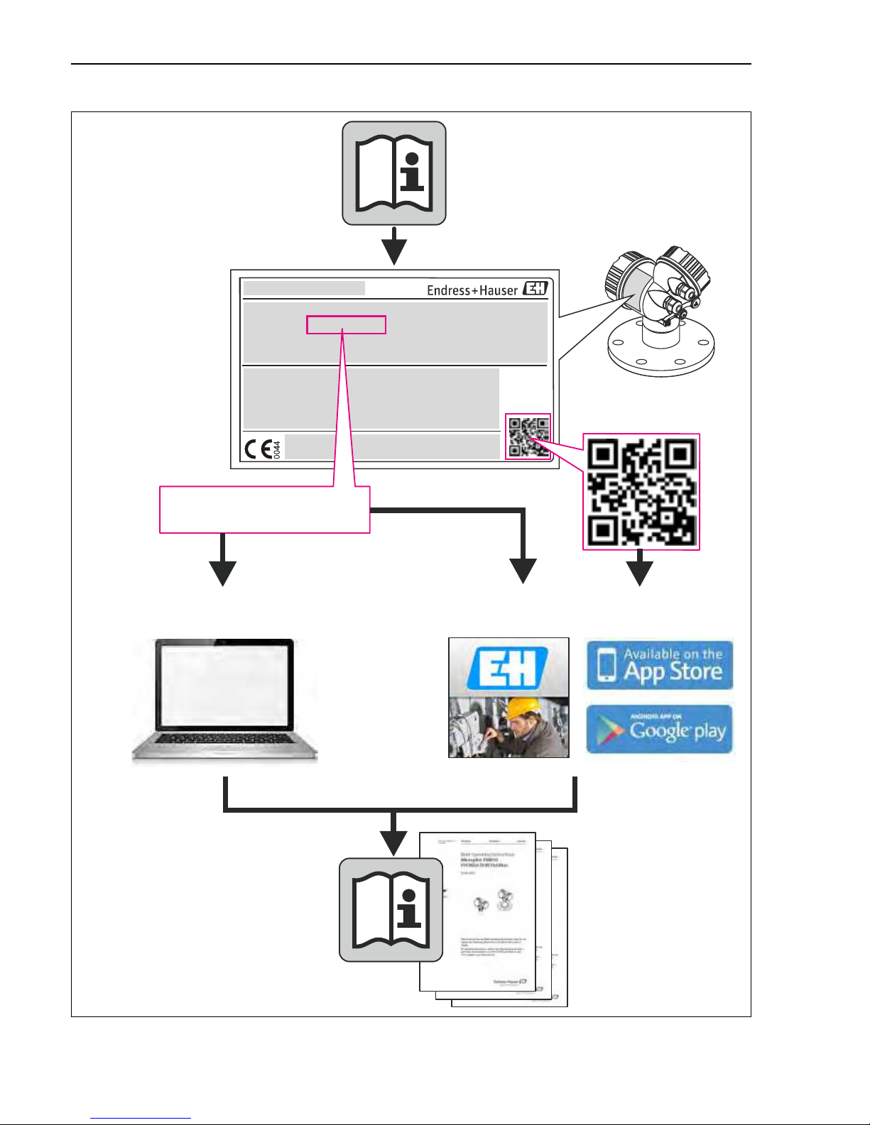
Detailed information about the device can be found in the Operating Instructions
and the other documentation:
Available for all device versions via:
– Internet:
www.endress.com/deviceviewer
– Smart phone/tablet: Endress+Hauser Operations App
Page 2
Deltabar M PROFIBUS PA
2 Endress+Hauser
A0023555
TAG No.: XXX000
Ser. No.: X000X000000
Order code 00X00-XXXX0XX0XXX
www.endress.com/deviceviewer Endress+Hauser Operations App
Serial number
Page 3

Deltabar M PROFIBUS PA Table of contents
Endress+Hauser 3
Table of contents
1 Safety instructions . . . . . . . . . . . . . . . . . . . . . . . . . . . . . . . . . . . . . . . . . . . . . . . . . 4
1.1 Designated use . . . . . . . . . . . . . . . . . . . . . . . . . . . . . . . . . . . . . . . . . . . . . . . . . . . . . . . . . . . . . . . . . . . . . . . . . . . 4
1.2 Installation, commissioning and operation . . . . . . . . . . . . . . . . . . . . . . . . . . . . . . . . . . . . . . . . . . . . . . . . . . . . . . . 4
1.3 Operational safety and process safety . . . . . . . . . . . . . . . . . . . . . . . . . . . . . . . . . . . . . . . . . . . . . . . . . . . . . . . . . . 4
1.4 Return . . . . . . . . . . . . . . . . . . . . . . . . . . . . . . . . . . . . . . . . . . . . . . . . . . . . . . . . . . . . . . . . . . . . . . . . . . . . . . . . . 4
1.5 Safety icons . . . . . . . . . . . . . . . . . . . . . . . . . . . . . . . . . . . . . . . . . . . . . . . . . . . . . . . . . . . . . . . . . . . . . . . . . . . . . 5
2 Product identification. . . . . . . . . . . . . . . . . . . . . . . . . . . . . . . . . . . . . . . . . . . . . . . 5
3 Installation . . . . . . . . . . . . . . . . . . . . . . . . . . . . . . . . . . . . . . . . . . . . . . . . . . . . . . 5
3.1 Installation position . . . . . . . . . . . . . . . . . . . . . . . . . . . . . . . . . . . . . . . . . . . . . . . . . . . . . . . . . . . . . . . . . . . . . . . 6
3.2 Closing the housing cover . . . . . . . . . . . . . . . . . . . . . . . . . . . . . . . . . . . . . . . . . . . . . . . . . . . . . . . . . . . . . . . . . . 7
3.3 Post-installation check . . . . . . . . . . . . . . . . . . . . . . . . . . . . . . . . . . . . . . . . . . . . . . . . . . . . . . . . . . . . . . . . . . . . . 8
4 Wiring. . . . . . . . . . . . . . . . . . . . . . . . . . . . . . . . . . . . . . . . . . . . . . . . . . . . . . . . . . 9
4.1 Connecting the device . . . . . . . . . . . . . . . . . . . . . . . . . . . . . . . . . . . . . . . . . . . . . . . . . . . . . . . . . . . . . . . . . . . . . 9
4.2 Connecting the measuring unit . . . . . . . . . . . . . . . . . . . . . . . . . . . . . . . . . . . . . . . . . . . . . . . . . . . . . . . . . . . . . . 10
4.3 Potential equalization . . . . . . . . . . . . . . . . . . . . . . . . . . . . . . . . . . . . . . . . . . . . . . . . . . . . . . . . . . . . . . . . . . . . . 11
4.4 Post-connection check . . . . . . . . . . . . . . . . . . . . . . . . . . . . . . . . . . . . . . . . . . . . . . . . . . . . . . . . . . . . . . . . . . . . 12
5 Operation . . . . . . . . . . . . . . . . . . . . . . . . . . . . . . . . . . . . . . . . . . . . . . . . . . . . . . 12
5.1 Operation without an operating menu . . . . . . . . . . . . . . . . . . . . . . . . . . . . . . . . . . . . . . . . . . . . . . . . . . . . . . . . 12
5.2 Operation with an operating menu . . . . . . . . . . . . . . . . . . . . . . . . . . . . . . . . . . . . . . . . . . . . . . . . . . . . . . . . . . . 14
5.3 Device identification and addressing . . . . . . . . . . . . . . . . . . . . . . . . . . . . . . . . . . . . . . . . . . . . . . . . . . . . . . . . . . 23
6 Commissioning without an operating menu . . . . . . . . . . . . . . . . . . . . . . . . . . . . . 24
6.1 Function check . . . . . . . . . . . . . . . . . . . . . . . . . . . . . . . . . . . . . . . . . . . . . . . . . . . . . . . . . . . . . . . . . . . . . . . . . 24
6.2 Position adjustment . . . . . . . . . . . . . . . . . . . . . . . . . . . . . . . . . . . . . . . . . . . . . . . . . . . . . . . . . . . . . . . . . . . . . . 25
7 Commissioning with an operating menu (onsite display/FieldCare). . . . . . . . . . . . 26
7.1 Function check . . . . . . . . . . . . . . . . . . . . . . . . . . . . . . . . . . . . . . . . . . . . . . . . . . . . . . . . . . . . . . . . . . . . . . . . . 26
7.2 Commissioning . . . . . . . . . . . . . . . . . . . . . . . . . . . . . . . . . . . . . . . . . . . . . . . . . . . . . . . . . . . . . . . . . . . . . . . . . 26
7.3 Position zero adjustment . . . . . . . . . . . . . . . . . . . . . . . . . . . . . . . . . . . . . . . . . . . . . . . . . . . . . . . . . . . . . . . . . . 28
7.4 Pressure measurement . . . . . . . . . . . . . . . . . . . . . . . . . . . . . . . . . . . . . . . . . . . . . . . . . . . . . . . . . . . . . . . . . . . . 29
7.5 Differential pressure measurement . . . . . . . . . . . . . . . . . . . . . . . . . . . . . . . . . . . . . . . . . . . . . . . . . . . . . . . . . . . 30
7.6 Flow measurement . . . . . . . . . . . . . . . . . . . . . . . . . . . . . . . . . . . . . . . . . . . . . . . . . . . . . . . . . . . . . . . . . . . . . . 31
7.7 Level measurement . . . . . . . . . . . . . . . . . . . . . . . . . . . . . . . . . . . . . . . . . . . . . . . . . . . . . . . . . . . . . . . . . . . . . . 33
Page 4

Safety instructions Deltabar M PROFIBUS PA
4 Endress+Hauser
1 Safety instructions
1.1 Designated use
The Deltabar M is a differential pressure transmitter for measuring differential pressure, level and
flow.
The manufacturer accepts no liability for damages resulting from incorrect use or use other than
that designated.
1.2 Installation, commissioning and operation
• The device must only be installed, connected, commissioned and maintained by qualified and
authorized specialists (e.g. electrical technicians) in full compliance with the instructions in
this manual, the applicable norms, legal regulations and certificates (depending on the
application).
• The specialist must have read and understood this manual and must follow the instructions it
contains. If you are unclear on anything in these Brief Operating Instructions, you must read
the Operating Instructions. The Operating Instructions provide detailed information on the
device/measuring system.
• The device may only be modified or repaired if such work is expressly permitted in the
Operating Instructions.
• If faults cannot be rectified, the device must be taken out of service and secured against
unintentional commissioning.
• Do not operate damaged devices. Mark them as defective.
1.3 Operational safety and process safety
• Alternative monitoring measures must be taken to ensure operational safety and process safety
during confiugration, testing and maintenance work on the device.
• The device is safely built and tested according to state-of-the-art technology and has left the
factory in perfect condition as regards technical safety. The applicable regulations and
European standards have been taken into account.
• Pay particular attention to the technical data on the nameplate.
• Devices for use in hazardous areas are fitted with an additional nameplate. If the device is to
be installed in an explosion hazardous area, then the specifications in the certificate as well as
all national and local regulations must be observed. The device is accompanied by separate
"Ex documentation", which is an integral part of this Operating Instructions. The installation
regulations, connection values and Safety Instructions listed in this Ex document must be
observed. The documentation number of the related Safety Instructions is also indicated on
the additional nameplate.
1.4 Return
Follow the instructions on returning the device as outlined in the Operating Instructions.
Page 5

Deltabar M PROFIBUS PA Product identification
Endress+Hauser 5
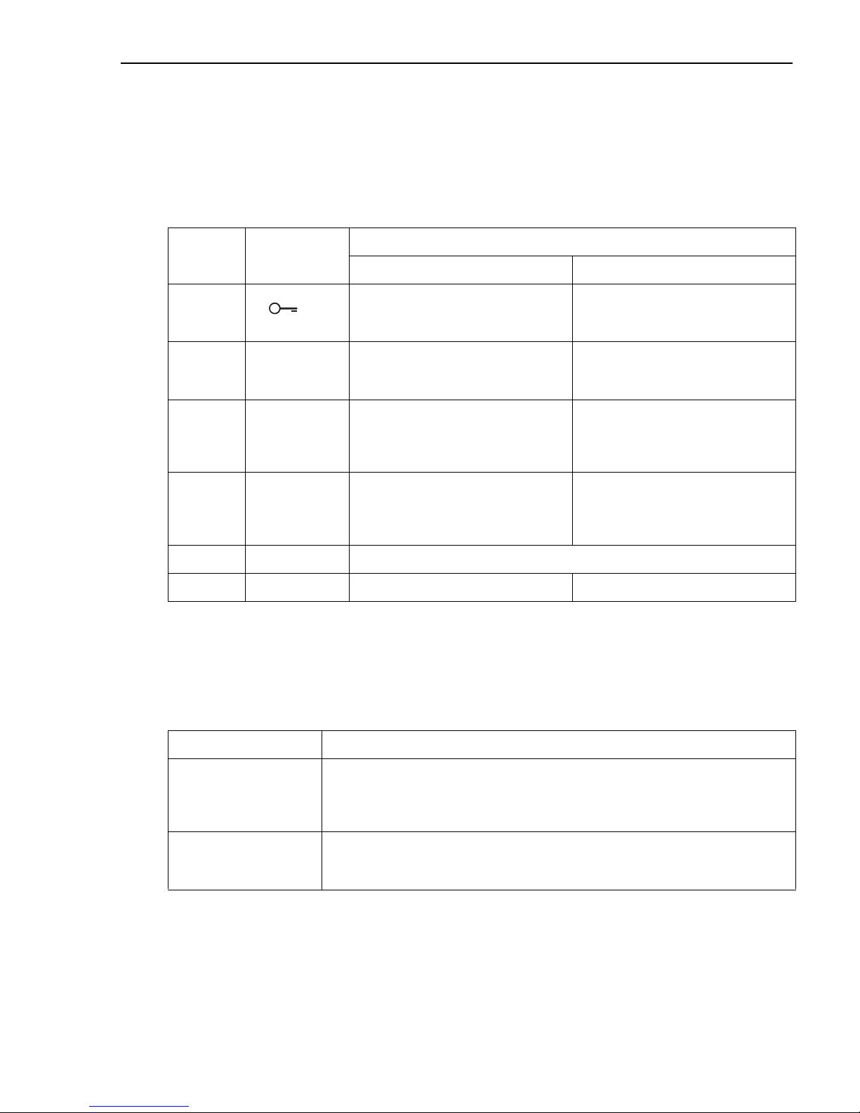
1.5 Safety icons
2 Product identification
The following options are available for identification of the measuring device:
• Nameplate specifications
• Order code with breakdown of the device features on the delivery note
• Enter serial numbers from nameplates in W@M Device Viewer
(www.endress.com/deviceviewer): All information about the measuring device is displayed.
For an overview of the technical documentation provided, enter the serial number from the
nameplates in the W@M Device Viewer (www.endress.com/deviceviewer).
3 Installation
!
Note!
Disassembly of the screws with item number (1) is not permissible under any circumstances and
will result in loss of warranty.
Symbol Meaning
#
Warning!
A warning highlights actions or procedures which, if not performed correctly, will lead to personal injury,
a safety hazard or destruction of the instrument.
"
Caution!
Caution highlights actions or procedures which, if not performed correctly, may lead to personal injury or
incorrect functioning of the instrument.
!
Note!
A note highlights actions or procedures which, if not performed correctly, may indirectly affect operation
or may lead to an instrument response which is not planned.
1
Page 6

Installation Deltabar M PROFIBUS PA
6 Endress+Hauser
3.1 Installation position
!
Note!
• Due to the orientation of the Deltabar M, there may be a shift in the measured value, i.e. when
the container is empty, the measured value does not display zero. You may correct this zero
point shift by a position adjustment in one of the following ways:
– via the operation keys on the electronics module ( ä 13, "Function of the operating
elements")
– via the operating menu ( ä 28, "Position zero adjustment")
• General recommendations for routing the impulse piping can be found in DIN 19210
"Methods for measurement of fluid flow; differential piping for flow measurement devices" or
the corresponding national or international standards.
• Using a three-valve or five-valve manifold allows for easy commissioning, installation and
maintenance without interrupting the process.
• When routing the impulse piping outdoors, ensure that sufficient anti-freeze protection is
used, e.g. by using pipe heat tracing.
• Install the impulse piping with a monotonic gradient of at least 10%.
• Endress+Hauser offers a mounting bracket for installing on pipes or walls (see Operating
Instructions BA00383P).
3.1.1 Installation position for flow measurement
!
Note!
For more information about differential pressure flow measurement refer to following
documents:
• Differential pressure flow measurements with orifices: Technical Information TI00422P
• Differential pressure flow measurement with Pitot tubes: Technical Information TI00425P
Flow measurement in gases
• Mount the Deltabar M above the measuring point so that the condensate which may be
present, can run off into the process piping.
Flow measurement in steam
• Mount the Deltabar M below the measuring point.
• Mount the condensate traps at the same level as the tapping points and at the same distance
to the Deltabar M.
• Prior to commissioning, fill the impulse piping to the height of the condensate traps.
Flow measurement in liquids
• Mount the Deltabar M below the measuring point so that the impulse piping is always filled
with liquid and gas bubbles can run back into the process piping.
• When measuring in media with solid parts, such as dirty liquids, installing separators and drain
valves is useful for capturing and removing sediment.
Page 7

Deltabar M PROFIBUS PA Installation
Endress+Hauser 7
3.1.2 Installation position for level measurement
Level measurement in an open container
• Mount the Deltabar M below the lower measuring connection so that the impulse piping is
always filled with liquid.
• The low-pressure is open to atmospheric pressure.
• When measuring in media with solid parts, such as dirty liquids, installing separators and drain
valves is useful for capturing and removing sediment.
Level measurement in a closed container
• Mount the Deltabar M below the lower measuring connection so that the impulse piping is
always filled with liquid.
• Always connect the low-pressure above the maximum level.
• When measuring in media with solid parts, such as dirty liquids, installing separators and drain
valves is useful for capturing and removing sediment.
Level measurement in a closed container with superimposed steam
• Mount the Deltabar M below the lower measuring connection so that the impulse piping is
always filled with liquid.
• Always connect the low-pressure above the maximum level.
• A condensate trap ensures constant pressure on the low-pressure.
• When measuring in media with solid parts, such as dirty liquids, installing separators and drain
valves is useful for capturing and removing sediment.
3.1.3 Installation position for differential pressure measurement
Differential pressure measurement in gases and steam
• Mount the Deltabar M above the measuring point so that the condensate which may be
present, can run off into the process piping.
Differential pressure measurement in liquids
• Mount the Deltabar M below the measuring point so that the impulse piping is always filled
with liquid and gas bubbles can run back into the process piping.
• When measuring in media with solid parts, such as dirty liquids, installing separators and drain
valves is useful for capturing and removing sediment.
3.2 Closing the housing cover
!
Note!
When closing the housing cover, please ensure that the thread of the cover and housing are free
from dirt, e.g. sand.If you feel any resistance when closing the cover, check the thread on both
again to ensure that they are free from dirt.
Page 8

Installation Deltabar M PROFIBUS PA
8 Endress+Hauser
3.3 Post-installation check
After installing the device, carry out the following checks:
• Are all screws firmly tightened?
• Are the housing covers screwed down tight?
• Are all locking screws and vent valves firmly tightened?
Page 9

Deltabar M PROFIBUS PA Wiring
Endress+Hauser 9
4 Wiring
4.1 Connecting the device
!
Note!
• When using the measuring device in hazardous areas, installation must comply with the
corresponding national standards and regulations and the Safety Instructions or Installation or
Control Drawings.
• A suitable circuit breaker has to be provided for the device in accordance with IEC/EN
61010.
• Devices with integrated overvoltage protection must be earthed.
• Protective circuits against reverse polarity, HF influences and overvoltage peaks are
integrated.
The procedure
1. Check if the supply voltage matches the specified supply voltage on the nameplate.
2. Switch off the supply voltage before connecting the device.
3. Remove housing cover.
4. Guide cable through the gland. Preferably use twisted, screened two-wire cable.
5. Connect device in accordance with the following diagram.
6. Screw down housing cover.
7. Switch on supply voltage.
Page 10

Wiring Deltabar M PROFIBUS PA
10 Endress+Hauser
P01-xMx5xxxx-04-xx-xx-xx-012
PROFIBUS PA electrical connection
1 Terminals for supply voltage and signal
2 Grounding terminal
3 Supply voltage: 9 to 32 VDC (Segment coupler)
4 External ground terminal
4.2 Connecting the measuring unit
!
Note!
For further information on the network structure and grounding and for further bus system
components such as bus cables, see the relevant documentation, e.g. Operating Instructions
BA00034S "PROFIBUS DP/PA: Guidelines for planning and commissioning" and the PNO
Guideline.
9...32 V DC
- +
1
2
3
4
on:P2=on:P2=
delta p
only
delta p
only
High off:SW
High off:SW
121
2
3
4
5
4
5
off:SWoff:SWon:on:
Ö
onon
off
off
damp
not used
damp
not used
AddressAddress
SW
HW
SW
HW
ZeroZero
onon
off
off
Display
Page 11

Deltabar M PROFIBUS PA Wiring
Endress+Hauser 11
4.2.1 Supply voltage
!
Note!
• When using the measuring device in hazardous areas, installation must comply with the
corresponding national standards and regulations and the Safety Instructions or Installation or
Control Drawings.
• All explosion protection data are given in separate documentation which is available upon
request. The Ex documentation is supplied as standard with all devices approved for use in
explosion hazardous areas.
4.2.2 Current consumption
11 mA ±1 mA, switch-on current corresponds to IEC 61158-2, Clause 21.
4.2.3 Cable specification
• Use a twisted, shielded two-wire cable, preferably cable type A.
• Terminals for wire cross-sections 0.5 to 2.5 mm
2
(20 to 14 AWG)
• Cable outer diameter: 5 to 9 mm (0.2 to 0.35 in) depends on the used cable gland (see
technical information)
!
Note!
For further information on the cable specifications, see Operating Instructions BA00034S
"PROFIBUS DP/PA: Guidelines for planning and commissioning", the PNO Guideline 2.092
"PROFIBUS PA User and Installation Guideline" and IEC 61158-2 (MBP).
4.2.4 Shielding/potential equalization
• You achieve optimum shielding against disturbances if the shielding is connected on both
sides (in the cabinet and on the device). If potential equalization currents are expected in the
plant, only ground shielding on one side, preferably at the transmitter.
• When using in hazardous areas, you must observe the applicable regulations.
Separate Ex documentation with additional technical data and instructions is included with
all Ex systems as standard.
4.3 Potential equalization
Hazardous area applications: Connect all devices to the local potential equalization.
Observe the applicable regulations.
Electronic version
PROFIBUS PA,
version for non-hazardous areas
9 to 32 V DC
Page 12

Operation Deltabar M PROFIBUS PA
12 Endress+Hauser
4.4 Post-connection check
Perform the following checks after completing electrical installation of the device:
• Does the supply voltage match the specifications on the nameplate?
• Is the device connected as per Section 3.1?
• Are all screws firmly tightened?
• Are the housing covers screwed down tight?
As soon as voltage is applied to the device, the green LED on the electronic insert lights up briefly
or the connected onsite display lights up.
5Operation
5.1 Operation without an operating menu
5.1.1 Position of operating elements
The operating key and DIP switches are located on the electronic insert in the device.
P01-Mxxxxxxx-19-xx-xx-xx-013
Fig. 1: PROFIBUS PA electronic insert
1 DIP switch for locking/unlocking parameters relevant to the measured value
2 DIP switch for switching damping on/off
3 Not assigned
4 "SW/Square root"; used to control the output characteristics
5 "SW/P2-High"; used to determine the high-pressure side
6 DIP switch for hardware address
7 DIP switch for bus address SW / HW
➂➁
➅
on
off
SW / P2=High
damping
1
2
345
➃➄
➀
➇
on:P2=
delta p
only
High off:SW
1
2
3
4
5
off:SWon:
Ö
on
off
damp
not used
Address
SW
HW
Zero
on
off
Display
➆
9
10
SW /
Ö
Page 13
Deltabar M PROFIBUS PA Operation
Endress+Hauser 13
Function of the DIP switches
Function of the operating elements
Performing position adjustment on site
!
Note!
• Operation must be unlocked. ä 22, Section 5.2.4 "Locking/unlocking operation".
8 Slot for optional onsite display
9 Operating key for position adjustment or reset (zero)
10 Green LED to indicate successful operation (Position adjustment, Reset, Warm start)
Switches Symbol/
labeling
Switch position
"off" "on"
1 The device is unlocked.
Parameters relevant to the measured
value can be modified.
The device is locked.
Parameters relevant to the measured
value cannot be modified.
2damping Damping is switched off.
The output signal follows measured value
changes without any delay.
Damping is switched on.
The output signal follows measured value
changes with the delay time .
1)
1) The value for the delay time can be configured via the operating menu ("Setup" -> "Damping").
Factory setting: = 2 s or as per order specifications.
4 SW/ The measuring mode is "Pressure" and
the output characteristics is "Linear", as
per the SW default setting.
The measuring mode is "flow" and the
output characteristics is "Square root"
regardless of the settings in the operating
menu.
5 SW/P2= High The high-pressure side (+/HP) is defined
by the setting in the operating menu.
("Setup" -> "High Press. Side")
The high-pressure side (+/HP) is
allocated to the P2 pressure connection
regardless of the setting in the operating
menu.
6 Address Set the device address using switches 1-7
7 SW / HW Hardware addressing Software addressing
Operating key(s) Meaning
"Zero"
pressed for at least
3seconds
Position adjustment (zero point correction)
Press key for at least 3 seconds. The LED on the electronic insert lights up briefly if the
pressure applied has been accepted for position adjustment.
See also the following Section "Performing position adjustment on site.''
"Zero"
pressed for at least
12 seconds
Reset
All parameters are reset to the order configuration.
Page 14

Operation Deltabar M PROFIBUS PA
14 Endress+Hauser
• The device is configured for the Pressure measuring mode as standard.
• The pressure applied must be within the nominal pressure limits of the sensor. See
information on the nameplate.
Perform position adjustment:
1. Pressure is present at device.
2. Press key for at least 3 seconds.
3. If the LED on the electronic insert lights up briefly, the pressure applied has been accepted
for position adjustment.
If the LED does not light up, the pressure applied was not accepted. Observe the input
limits. For error messages, see Operating Instructions.
5.1.2 Locking/unlocking operation
Once you have entered all the parameters, you can lock your entries against unauthorized and
undesired access.
!
Note!
If operation is locked by means of the DIP switch, you can only unlock operation again by means
of the DIP switch. If operation is locked by means of the operating menu, you can only unlock
operation again using the operating menu.
Locking/unlocking via DIP switches
DIP switch 1 on the electronic insert is used to lock/unlock operation.
ä 13, "Function of the DIP switches".
5.2 Operation with an operating menu
5.2.1 Operation concept
The operation concept makes a distinction between the following user roles:
User role Meaning
Operator Operators are responsible for the devices during normal "operation". This is usually limited to reading process
values either directly at the device or in a control room. If the work with the devices extends beyond value
read-off tasks, the tasks involve simple, application-specific functions that are used in operation. Should an error
occur, these users simple forward the information on the errors but do not intervene themselves.
Service
engineer/
technician
Service engineers usually work with the devices in the phases following device commissioning.
They are primarily involved in maintenance and troubleshooting activities for which simple settings have to be
made at the device.
Technicians work with the devices over the entire life cycle of the product.
Thus, commissioning and advanced settings and configurations are some of the tasks they have to carry out.
Page 15

Deltabar M PROFIBUS PA Operation
Endress+Hauser 15
5.2.2 Structure of the operating menu
Expert Experts work with the devices over the entire product life cycle, but their device requirements are often
extremely high. Individual parameters/functions from the overall functionality of the devices are required for this
purpose time and again.
In addition to technical, process-oriented tasks, experts can also perform administrative tasks (e.g. user
administration).
"Experts" can avail of the entire parameter set.
User role Meaning
User role Submenu Meaning/use
Operator Language Only consists of the "Language" parameter (000) where the operating language for the device is
specified.
The language can always be changed even if the device is locked.
Operator Display/operat. Contains parameters that are needed to configure the measured value display (selecting the
values displayed, display format, etc.).
With this submenu, users can change the measured value display without affecting the actual
measurement.
Service
engineer/
technician
Setup Contains all the parameters that are needed to commission measuring operations. This submenu
has the following structure:
• Standard setup parameters
A wide range of parameters, which can be used to configure a typical application, is available
at the start. The measuring mode selected determines which parameters are available.
After making settings for all these parameters, the measuring operation should be completely
configured in the majority of cases.
• "Extended setup" submenu
The "Extended setup" submenu contains additional parameters for more in-depth
configuration of the measurement operation to convert the measured value and to scale the
output signal.
This menu is split into additional submenus depending on the measuring mode selected.
Service
engineer/
technician
Diagnosis Contains all the parameters that are needed to detect and analyze operating errors. This
submenu has the following structure:
• Diagnostic list
Contains up to 10 error messages currently pending.
• Event logbook
Contains the last 10 error messages (no longer pending).
• Instrument info
Contains information on the device identification.
• Measured values
Contains all the current measured values
• Simulation
Is used to simulate pressure, level, flow and alarm/warning.
• Factory reset
Page 16

Operation Deltabar M PROFIBUS PA
16 Endress+Hauser
5.2.3 Operation with a device display (optional)
A 4-line liquid crystal display (LCD) is used for display and operation. The onsite display shows
measured values, dialog texts, fault messages and notice messages.
For easy operation the display can be taken out of the housing (see figure steps 1 to 3). It is
connected to the device through a 90 mm (3.54 in) cable.
The display of the device can be turned in 90° stages (see figure steps 4 to 6).
Depending on the orientation of the device, this makes it easy to operate the device and read the
measured values.
P01-Mxxxxxxx-19-xx-xx-xx-008
Expert Expert Contains all the parameters of the device (including those in one of the submenus). The "Expert"
submenu is structured by the function blocks of the device. It thus contains the following
submenus:
• System
Contains general device parameters that neither affect measurement nor integration into a
distributed control system.
• Measurement
Contains all the parameters for configuring the measurement.
• Communication
Contains the parameters of the PROFIBUS PA interface.
• Application
Contains all the parameters for configuring the functions that go beyond the actual
measurement (e.g. totalizer).
• Diagnosis
Contains all the parameters that are needed to detect and analyze operating errors.
User role Submenu Meaning/use
1.
2. 3.
4. 5. 6.
Page 17

Deltabar M PROFIBUS PA Operation
Endress+Hauser 17
Functions:
• 8-digit measured value display including sign and decimal point.
• Bar graph as graphic display of the standardized value of the Analog Input Block (see
Operating Instructions)
• Three keys for operation
• Simple and complete menu guidance as parameters are split into several levels and groups
• Each parameter is given a 3-digit parameter code for easy navigation
• Possibility of configuring the display to suit individual requirements and preferences, such as
language, alternating display, display of other measured values such as sensor temperature,
contrast setting.
• Comprehensive diagnostic functions (fault and warning message etc.)
P01-Mxxxxxxx-07-xx-xx-xx-002
E
+
–
Symbol
Operating keys
ValueDevice tag
Measured value display
Unit
Bargraph
Operating menu
Parameter with selection list
Freely editable parameter
Direct
Access
Code
Value that
can be
edited
Selection
options
Header line
Information
line
Main line
Page 18

Operation Deltabar M PROFIBUS PA
18 Endress+Hauser
The following table illustrates the symbols that can appear on the onsite display. Four symbols
can occur at one time.
Operating keys on the display and operating module
Symbol Meaning
Lock symbol
The operation of the device is locked. To unlock the device, ä 22, Locking/unlocking operation.
Communication symbol
Data transfer via communication
Square root symbol
Active measuring mode "Flow measurement"
Error message "Out of specification"
The device is being operated outside its technical specifications (e.g. during warmup or cleaning
processes).
Error message "Service mode"
The device is in the service mode (during a simulation, for example).
Error message "Maintenance required"
Maintenance is required. The measured value remains valid.
Error message "Failure detected"
An operating error has occurred. The measured value is no longer valid.
S
C
M
F
Operating key(s) Meaning
O
– Navigate downwards in the picklist
– Edit the numerical values and characters within a function
S
– Navigate upwards in the picklist
– Edit the numerical values and characters within a function
F
–Confirm entry
– Jump to the next item
– Selection of a menu item and activation of the editing mode
O
and
F
Contrast setting of onsite display: darker
S
and
F
Contrast setting of onsite display: brighter
Page 19

Deltabar M PROFIBUS PA Operation
Endress+Hauser 19
Parameters with a picklist
Example: selecting "Deutsch" as the language.
O
and
S
ESC functions:
– Exit the edit mode for a parameter without saving the changed value.
– You are in a menu at a selection level. Each time you press the keys simultaneously, you go up a level
in the menu.
Operating key(s) Meaning
Onsite display Operation
P01-PMD55xxx-19-x x-xx-xx-002
"English" is set as the language (default value). A ✓ in front of the
menu text indicates the active option.
P01-PMD55xxx-19-x x-xx-xx-001
Select "Deutsch" with "+" or "–" .
P01-PMD55xxx-19-x x-xx-xx-000
1. Confirm your choice with "E". A ✓ in front of the menu text
indicates the active option. ("Deutsch" is now selected as the
menu language.)
2. Exit the edit mode for the parameter with "E" .
Page 20

Operation Deltabar M PROFIBUS PA
20 Endress+Hauser
User-definable parameters
Example: changing the damping function from 2.0 s to 30.0 s.
Onsite display Operation
P01-xxxxxxxx-19-xx-xx-en-001
The onsite display shows the parameter to be changed. The value
highlighted in black can be changed. The unit "s" is prespecified and
cannot be changed.
P01-xxxxxxxx-19-xx-xx-en-002
1. Press "+" or "–" to get to the editing mode.
2. The first digit is highlighted in black.
P01-xxxxxxxx-19-xx-xx-en-003
1. Use "+" to change "2" to "3".
2. Confirm "3" with "E". The cursor jumps to the next position
(highlighted in black).
P01-xxxxxxxx-19-xx-xx-en-004
The decimal point is highlighted in black. This means you can now
edit this digit.
P01-xxxxxxxx-19-xx-xx-en-005
1. Press "+" or "–" until "0" is displayed.
2. Confirm "0" with "E".
The cursor goes to the next position. is displayed and
highlighted in black. See next graphic.
P01-xxxxxxxx-19-xx-xx-en-006
Use "E" to save the new value and exit the editing mode. See
next graphic.
Page 21

Deltabar M PROFIBUS PA Operation
Endress+Hauser 21
Accepting the pressure present
Example: setting position adjustment
P01-xxxxxxxx-19-xx-xx-en-007
The new value for the damping is 30.0 s.
– Go to the next parameter with "E" .
– You can get back to the editing mode with "+" or "–".
Onsite display Operation
P01-PMD55xxx-19-x x-xx-xx-009
The pressure for position adjustment is present at the device.
P01-PMD55xxx-19-x x-xx-xx-010
Use "+" or "–" to switch to the "Confirm" option. The active option is
highlighted in black.
P01-PMD55xxx-19-x x-xx-xx-011
Accept the pressure present as position adjustment with the "E" key.
The device confirms the adjustment and goes back to the "Pos. zero
adjust" parameter.
P01-PMD55xxx-19-x x-xx-xx-009
Exit the edit mode for the parameter with "E" .
Onsite display Operation
Page 22

Operation Deltabar M PROFIBUS PA
22 Endress+Hauser
5.2.4 Locking/unlocking operation
Once you have entered all the parameters, you can lock your entries against unauthorized and
undesired access.
Locked operation is indicated as follows:
• By the symbol on the onsite display
• The parameters are grayed out in FieldCare and the handheld terminal, which means they
cannot be edited. Indicated in the corresponding "Lockstate" parameter.
Parameters which refer to how the display appears, e.g. "Language (000)", can still be altered.
!
Note!
If operation is locked by means of the DIP switch, you can only unlock operation again by means
of the DIP switch. If operation is locked by means of the operating menu, you can only unlock
operation again using the operating menu.
The "Operator code (021)" parameter is used to lock and unlock the device.
The release code is defined in the "Code definition (023)" parameter.
Parameter name Description
Operator code (021)
Entry
Menu path:
Setup Extended
setup Operator code
Use this function to enter a code to lock or unlock operation.
User input:
• To lock: Enter a number the release code (value range: 1 to 9999).
• To unlock: Enter the release code.
!
Note!
The release code is "0" in the order configuration. Another release code can be defined in the "Code
definition (023)" parameter.
If the user has forgotten the release code, the release code can be visible by entering the number
"5864".
Factory setting:
0
Parameter name Description
Code definition (023)
Entry
Menu path:
Setup Extended
setup Code definition
Use this function to enter a release code with which the device can be unlocked.
User input:
• A number between 0 and 9999
Factory setting:
0
Page 23

Deltabar M PROFIBUS PA Operation
Endress+Hauser 23
5.3 Device identification and addressing
Please note the following:
• An address must be assigned to each PROFIBUS PA device. The control system/master can
only recognize the device if the address is set correctly.
• Each address can only be assigned once in any PROFIBUS PA network.
• Device addresses in the range from 0 to 125 are valid.
• The address "126" configured at the factory can be used for functional device testing and to
connect to a PROFIBUS PA network already in operation. This address must be changed
subsequently to add additional devices.
• On leaving the factory, all devices are delivered with the default address 126 and software
addressing.
• The FieldCare operating program is delivered with the default address 1.
There are two ways to assign the device address to a Deltabar:
• Via an operating program of the DP Class 2 master, such as FieldCare or
• Onsite via DIP switches.
P01-Mxxxxxxx-19-xx-xx-xx-018
Fig. 2: Setting the device address via DIP switches
1 If necessary, remove onsite display (optional)
2 Set the hardware address via the DIP switches
5.3.1 Hardware addressing
A hardware address is set as follows:
1. Set the DIP switch 8 (SW/HW) to "Off".
2. Set the address with DIP switches 1 to 7.
3. The change of address takes effect after 10 seconds. The device is restarted.
➀➁
2
3
4
5
678
1
E
+
–
on:P2=
delta p
only
High off:SW
1
2
3
4
5
off:SWon:
Ö
on
off
damp
not used
Address
SW
HW
Zero
on
off
Display
on
off
Address
SW
HW
2 + 8 = 10
DIP switch 1234567
Value when set to "On" 1 2 4 8 16 32 64
Value when set to "Off" 0 0 0 0 0 0 0
Page 24

Commissioning without an operating menu Deltabar M PROFIBUS PA
24 Endress+Hauser
5.3.2 Software addressing
A software address is set as follows:
1. Set the DIP switch 8 (SW/HW) to "On" (factory setting).
2. The device is restarted.
3. The device reports its current address. Factory setting: 126
4. Set the address via the configuration program.
See the next section for information on how to enter a new address via FieldCare.
For other operating programs, see the corresponding operating manual.
6 Commissioning without an operating menu
#
Warning!
• If a pressure smaller than the minimum permitted pressure or greater than the maximum
permitted pressure is present at the device, the following messages are output in succession:
1. "S140 Working range P" or "F140 Working range P"
)
2. "S841 Sensor range" or "F841 Sensor range"
1)
!
Note!
The device is configured for the Pressure measuring mode as standard. The measuring range and
the unit in which the measured value is transmitted correspond to the specifications on the
nameplate.
6.1 Function check
Carry out a post-installation and a post-connection check as per the checklist before
commissioning the device.
• "Post-installation check" checklist ä 8
• "Post-connection check" checklist ä 12
1) Depending on the setting in the "Alarm behav. P (050) parameter.
Page 25

Deltabar M PROFIBUS PA Commissioning without an operating menu
Endress+Hauser 25
6.2 Position adjustment
The following functions are possible by means of the key on the electronic insert:
• Position adjustment (zero point correction)
• Device reset (see Operating Instructions)
!
Note!
• Operation must be unlocked. ä 22, "Locking/unlocking operation"
• The device is configured for the "Pressure" measuring mode as standard.
• The pressure applied must be within the nominal pressure limits of the sensor. See
information on the nameplate.
Carrying out position adjustment
Pressure is present at device.
Press the "Zero" key for at least 3 s.
Does the LED on the electronic insert light up briefly?
Yes No
Applied pressure for position adjustment has been
accepted.
1)
Applied pressure for position adjustment has not been
accepted. Observe the input limits.
1) Observe warning on commissioning ( ä 24)
Page 26

Commissioning with an operating menu (onsite display/FieldCare) Deltabar M PROFIBUS PA
26 Endress+Hauser
7 Commissioning with an operating menu
(onsite display/FieldCare)
#
Warning!
• If a pressure smaller than the minimum permitted pressure or greater than the maximum
permitted pressure is present at the device, the following messages are output in succession:
1. "S140 Working range P" or "F140 Working range P"
)
2. "S841 Sensor range" or "F841 Sensor range"
2)
!
Note!
The device is configured for the Pressure measuring mode as standard. The measuring range and
the unit in which the measured value is transmitted correspond to the specifications on the
nameplate.
7.1 Function check
Carry out a post-installation and a post-connection check as per the checklist before
commissioning the device.
• "Post-installation check" checklist ä 8
• "Post-connection check" checklist ä 12
7.2 Commissioning
Commissioning comprises the following steps:
1. Function check ä 26
2. Selecting the language, measuring mode and pressure unit ä 26
3. Position adjustment ä 28
4. Configuring measurement:
– Pressure measurement ä 29 ff
– Flow measurement ä 31 ff
– Level measurement ä 33 ff
2) depending on the setting in the "Alarm behav. P" (050) parameter
Page 27

Deltabar M PROFIBUS PA Commissioning with an operating menu (onsite display/FieldCare)
Endress+Hauser 27
7.2.1 Selecting the language, measuring mode and pressure unit
Language selection
Measuring mode selection
Pressure unit selection
Parameter name Description
Language (000)
Options
Menu path:
Main menu Language
Select the language for the onsite display.
Options:
• English
• Possibly another language (as selected when ordering the device)
• One further language (language of the manufacturing plant)
Factory setting:
English
Parameter name Description
Measuring mode
(005)
Options
Menu path:
Setup Measuring
mode (005)
Select the measuring mode.
The operating menu is structured differently depending on the measuring mode selected.
!
Note!
If the measuring mode is changed, no conversion takes place. If necessary, the device has to be
recalibrated after the measuring mode has been changed.
Options:
• Pressure
• Level
•Flow
Factory setting:
Pressure
Parameter name Description
Press. eng. unit (125)
Options
Menu path:
Setup Press. eng. unit
(125)
Select the pressure unit.
If a new pressure unit is selected, all pressure-specific parameters are converted and displayed with the
new unit.
Options:
• mbar, bar
• mmH2O, mH2O,
•inH2O, ftH2O
• Pa, kPa, MPa
•psi
•mmHg, inHg
•kgf/cm
2
Factory setting:
mbar or bar depending on the sensor nominal measuring range, or as per order specifications
Page 28

Commissioning with an operating menu (onsite display/FieldCare) Deltabar M PROFIBUS PA
28 Endress+Hauser
7.3 Position zero adjustment
The pressure resulting from the orientation of the device can be corrected here.
Parameter name Description
Corrected press.
(172)
Display
Menu path:
Setup Corrected
press. (172)
Displays the measured pressure after sensor trim and position adjustment.
!
Note!
If this value is not equal to "0", it can be corrected to "0" by the position adjustment.
Pos. zero adjust (007)
(Deltabar M and
relative pressure
sensor)
Options
Menu path:
Setup Pos. zero
adjust (007) (Deltabar
and relative pressure
sensor)
Position adjustment – the pressure difference between zero (set point) and the measured pressure need
not be known.
Example:
– Measured value = 2.2 mbar (0.032 psi)
– Correct the measured value via the "Pos. zero adjust (007) (Deltabar and relative pressure sensor)"
parameter with the "Confirm" option. This means that you are assigning the value 0.0 to the
pressure present.
– Measured value (after pos. zero adjust) = 0.0 mbar
Options
•Confirm
• Abort
Factory setting:
Abort
Calib. offset (192)
(008)
(absolute pressure
sensor)
Entry
Menu path:
Setup Calib. offset
(192)
Position adjustment – the pressure difference between the set point and the measured pressure must
be known.
Example:
– Measured value = 982.2 mbar (14.25 psi)
– You correct the measured value with the value entered (e.g. 2.2 mbar (0.032 psi)) via the "Calib.
offset (192)" parameter. This means that you are assigning the value 980.0 (14.21 psi) to the
pressure present.
– Measured value (after calib. offset) = 980.0 mbar (14.21 psi)
Factory setting:
0.0
Page 29

Deltabar M PROFIBUS PA Commissioning with an operating menu (onsite display/FieldCare)
Endress+Hauser 29
7.4 Pressure measurement
7.4.1 Calibration without reference pressure (dry calibration)
Example:
In this example, a device with a 400 mbar (6 psi) sensor is configured for the 0 to +300 mbar
(4.35 psi) measuring range, i.e. 0 mbar and 300 mbar (4.35 psi) are assigned.
Prerequisite:
This is a theoretical calibration, i.e. the pressure values for the lower and upper range are known.
!
Note!
Due to the orientation of the device, there may be pressure shifts in the measured value, i.e. the
measured value is not zero in a pressureless condition. For information on how to perform
position adjustment, see ä 28. Calibration is possible only using FieldCare.
Description
1 Select the "Pressure" measuring mode via the "Measuring mode
(005)" parameter.
Menu path: Setup Measuring mode (005)
2 Select a pressure unit via the "Press. eng. unit (125)" parameter,
here "mbar" for example.
Menu path: Setup Press. eng. unit (125)
3 Where necessary scale the "Output value (Out Value)" of the
Analog Input Block (see Operating Instructions).
4Result:
The measuring range is configured for 0 to +300 mbar (4.35 psi).
Page 30

Commissioning with an operating menu (onsite display/FieldCare) Deltabar M PROFIBUS PA
30 Endress+Hauser
7.5 Differential pressure measurement
7.5.1 Preparatory steps
!
Note!
• Before calibrating the device, the impulse piping must be cleaned and filled with medium.
See the following table.
Valves Meaning Preferred installation
1 Close 3.
P01-PMD55xxx-11-xx-xx-xx-013
Above: preferred installation for gases
Below: preferred installation for liquids
IDeltabar M
II Three-valve manifold
III Separator
1, 5 Drain valves
2, 4 Inlet valves
3 Equalizing valve
6, 7 Vent valves on Deltabar M
A, B Shut-off valve
2 Fill measuring system with medium.
Open A, B, 2, 4. Medium flows in.
3 Clean impulse piping if necessary:
1)
– by blowing out with compressed air in the case of gases
– by rinsing out in the case of liquids.
Close 2 and 4. Block off device.
Open 1 and 5.
Blow out/rinse out impulse
piping.
Close 1 and 5.
Close valves after cleaning.
4 Vent device.
Open 2 and 4. Introduce medium.
Close 4. Close low-pressure side.
Open 3. Balance positive and low-pressure
side.
Open 6 and 7 briefly, then close
them again.
Fill device completely with
medium and remove air.
5 Set measuring point in operation.
Close 3. Shut off high-pressure side from
low-pressure side.
Open 4. Connect low-pressure side.
Now
–1
, 3, 5, 6 and 7 are closed.
– 2 and 4 are open.
– A and B open (if present).
6 Carry out calibration if necessary. See also page 28.
1) for arrangement with 5 valves
I
II
+–
–
P2
+
P1
6
7
–
P2
+
P1
6
7
3
24
A B
A
B
+
1
5
24
3
II
I
IIIIII
Page 31

Deltabar M PROFIBUS PA Commissioning with an operating menu (onsite display/FieldCare)
Endress+Hauser 31
7.6 Flow measurement
7.6.1 Information on flow measurement
In the "Flow" measuring mode, the device determines a volume or mass flow value from the
differential pressure measured. The differential pressure is generated by means of primary
elements such as pitot tubes or orifice plates and depends on the volume or mass flow. Four flow
types are available: volume flow, norm volume flow (European norm conditions), standard
volume flow (American standard conditions), mass flow and flow in %.
In addition, the Deltabar M software provides two totalizers as standard. The totalizers
integrates the volume or the mass flow. The counting function and the unit can be set separately
for both totalizers. The first totalizer (totalizer 1) can be reset to zero at any time while the
second (totalizer 2) totalizes the flow from commissioning onwards and cannot be reset.
!
Note!
The totalizers are not available for the flow type "Flow in %".
7.6.2 Preparatory steps
!
Note!
• Before calibrating the Deltabar M, the impulse piping must be cleaned and filled with
medium. See the following table.
Page 32

Commissioning with an operating menu (onsite display/FieldCare) Deltabar M PROFIBUS PA
32 Endress+Hauser
Valves Meaning Preferred installation
1 Close 3.
P01-PMD55xxx-11-xx-xx-xx-013
Above: preferred installation for gases
Below: preferred installation for liquids
IDeltabar M
II Three-valve manifold
III Separator
1, 5 Drain valves
2, 4 Inlet valves
3 Equalizing valve
6, 7 Vent valves on Deltabar M
A, B Shut-off valves
2 Fill measuring system with medium.
Open A, B, 2, 4. Medium flows in.
3 Clean impulse piping if necessary
1)
:
– by blowing out with compressed air in the case of gases
– by rinsing out in the case of liquids.
Close 2 and 4. Block off device.
Open 1 and 5.
Blow out/rinse out impulse
piping.
Close 1 and 5.
Close valves after cleaning.
4 Vent device.
Open 2 and 4. Introduce medium.
Close 4. Close low-pressure side.
Open 3. Balance positive and low-pressure
side.
Open 6 and 7 briefly, then close
them again.
Fill device completely with
medium and remove air.
5 Carry out position zero adjustment ( ä 28) if the following
conditions are met. If the conditions are not met, then do not carry
out the pos. zero adjustment until after step 6.
Conditions:
– The process cannot be blocked off.
– The tapping points (A and B) are at the same geodetic height.
6 Set measuring point in operation.
Close 3. Shut off high-pressure side from
low-pressure side.
Open 4. Connect low-pressure side.
Now
–1
, 3, 5, 6 and 7 are closed.
– 2 and 4 are open.
– A and B open (if present).
7 Carry out position zero adjustment ( ä 28) if the flow can be
blocked off. In this case, step 5 is not applicable.
8 Carry out calibration ä 28.
1) for arrangement with 5 valves
I
II
+–
–
P2
+
P1
6
7
–
P2
+
P1
6
7
3
24
A B
A
B
+
1
5
24
3
II
I
IIIIII
Page 33

Deltabar M PROFIBUS PA Commissioning with an operating menu (onsite display/FieldCare)
Endress+Hauser 33
7.7 Level measurement
7.7.1 Preparatory steps
Open container
!
Note!
• Before calibrating the device, the impulse piping must be cleaned and filled with medium.
See the following table.
Valves Meaning Installation
1 Fill container to a level above the lower tap.
P01-PMD55xxx-11-xx-xx-xx-008
Open container
IDeltabar M
II Separator
6 Vent valves on Deltabar M
A Shut-off valve
B Drain valve
2 Fill measuring system with medium.
Open A. Open shut-off valve.
3Vent device.
Open 6 briefly, then close it
again.
Fill device completely with
medium and remove air.
4 Set measuring point in operation.
Now
– B and 6 are closed.
– A is open.
5 Carry out calibration according to one of the following methods:
• "in pressure" - with reference pressure ( ä 36)
• "in pressure" - without reference pressure ( ä 38)
• "in height" - with reference pressure ( ä 40)
• "in height" - without reference pressure ( ä 43)
+
A
B
II
I
p
atm
–
P2
+
P1
6
Page 34

Commissioning with an operating menu (onsite display/FieldCare) Deltabar M PROFIBUS PA
34 Endress+Hauser
Closed container
!
Note!
• Before calibrating the device, the impulse piping must be cleaned and filled with medium.
See the following table.
Valves Meaning Installation
1 Fill container to a level above the lower tap.
P01-PMD55xxx-11-xx-xx-xx-009
Closed container
IDeltabar M
II Three-valve manifold
III Separator
1, 5 Drain valves
2, 4 Inlet valves
3 Equalizing valve
6, 7 Vent valve on Deltabar M
A, B Shut-off valve
2 Fill measuring system with medium.
Close 3. Shut off high-pressure side from
low-pressure side.
Open A and B. Open shut-off valves.
3 Vent high-pressure side (empty low-pressure side if necessary).
Open 2 and 4. Introduce medium on
high-pressure side.
Open 6 and 7 briefly, then close
them again.
Fill high-pressure side completely
with medium and remove air.
4 Set measuring point in operation.
Now
– 3, 6 and 7 are closed.
– 2, 4, A and B are open.
5 Carry out calibration according to one of the following methods:
• "in pressure" - with reference pressure ( ä 36)
• "in pressure" - without reference pressure ( ä 38)
• "in height" - with reference pressure ( ä 40)
• "in height" - without reference pressure ( ä 43)
+
–
A
B
3
2
4
1
5
II
I
IIIIII
–
P2
+
P1
6
7
Page 35

Deltabar M PROFIBUS PA Commissioning with an operating menu (onsite display/FieldCare)
Endress+Hauser 35
Closed container with superimposed steam
!
Note!
• Before calibrating the device, the impulse piping must be cleaned and filled with medium.
See the following table.
Valves Meaning Installation
1 Fill container to a level above the lower tap.
P01-PMD55xxx-11-xx-xx-xx-010
Closed container with superimposed steam
IDeltabar M
II Three-valve manifold
III Separator
1, 5 Drain valves
2, 4 Inlet valves
3 Equalizing valve
6, 7 Vent valves on Deltabar M
A, B Shut-off valves
2 Fill measuring system with medium.
Open A and B. Open shut-off valves.
Fill the negative impulse piping to the level of the condensate trap.
3Vent device.
Open 2 and 4. Introduce medium.
Close 4. Close low-pressure side.
Open 3. Balance positive and low-pressure
side.
Open 6 and 7 briefly, then close
them again.
Fill device completely with
medium and remove air.
4 Set measuring point in operation.
Close 3. Shut off high-pressure side from
low-pressure side.
Open 4. Connect low-pressure side.
Now
– 3, 6 and 7 are closed.
– 2, 4, A and B are open.
5 Carry out calibration according to one of the following methods:
• "in pressure" - with reference pressure ( ä 36)
• "in pressure" - without reference pressure ( ä 38)
• "in height" - with reference pressure ( ä 40)
• "in height" - without reference pressure ( ä 43)
+
–
A
B
3
2
4
1
5
II
I
IIIIII
–
P2
+
P1
6
7
Page 36

Commissioning with an operating menu (onsite display/FieldCare) Deltabar M PROFIBUS PA
36 Endress+Hauser
7.7.2 "In pressure" level selection
Calibration with reference pressure (wet calibration)
Example:
In this example, the level in a tank should be measured in "m". The maximum level is 3 m (9.8
ft). The pressure range is due to the filling height and the density.
Prerequisite:
• The measured variable is in direct proportion to the pressure.
• The tank can be filled and emptied.
!
Note!
The values entered for "Empty calib. (028)/Full calib. (031)" and the pressures present at the
device must be at least 1% apart. The value will be rejected, and a warning message displayed,
if the values are too close together. Further limit values are not checked; i.e. the values entered
must be appropriate for the sensor and the measuring task so that the measuring device can
measure correctly.
Description
1 Perform "position adjustment" ä 28.
2 Select the "Level" measuring mode via the "Measuring mode
(005)" parameter.
Menu path: Setup Measuring mode (005)
3 Select a pressure unit via the "Press. eng. unit (125)" parameter,
here "mbar" for example.
Menu path: Setup Press. eng. unit (125)
4 Select the "in pressure" level mode by means of the "Level
selection (024)" parameter.
Menu path: Setup Extended Setup Level Level selection
(024)
Page 37

Deltabar M PROFIBUS PA Commissioning with an operating menu (onsite display/FieldCare)
Endress+Hauser 37
!
Note!
The measured variables %, level, volume and mass are available for this level mode see
parameter "Unit before lin (025)" in the Operating Instructions.
5 Select a level unit by means of the "Unit before lin (025)"
parameter, here "m" for example.
Menu path: Setup Extended Setup Level Unit before lin
(025)
P01-xxxxxxxx-05-xx-xx-xx-011
Fig. 3: Calibration with reference pressure –
wet calibration
1 See Table, Step 7.
2 See Table, Step 8.
6 Select the "Wet" option by means of the "Calibration mode
(027)" parameter.
Menu path: Setup Extended Setup Level Calibration
mode (027)
7 The pressure for the lower calibration point is present at the
device, here 0 mbar for example.
Select the "Empty calib. (028)" parameter.
Menu path: Setup Extended Setup Level Empty calib.
(028)
Enter the level value, here 0 m for example. The pressure value
present is assigned to the lower level value by confirming the
value.
8 The pressure for the upper calibration point is present at the
device, here 300 mbar (4.35 psi) for example.
Select the "Full calib. (031)" parameter.
Menu path: Setup Extended Setup Level Full calib.
(031)
Enter the level value, here 3 m (9.8 ft) for example. The pressure
value present is assigned to the upper level value by confirming
the value.
9 If calibration is performed with a medium other than the process
medium, enter the density of the calibration medium in "Adjust
density (034)".
Menu path: Setup Extended Setup Level Adjust density
(034)
10 If calibration was performed with a medium other than the
process medium, specify the density of the process medium in
the "Process density (035)" parameter.
Menu path: Setup Extended setup Level Process density
(035).
11 Result:
The measuring range is set for 0 to 3 m (9.8 ft).
Description
3
0
h
[m]
0 300
p
[mbar]
➀
➁
Page 38

Commissioning with an operating menu (onsite display/FieldCare) Deltabar M PROFIBUS PA
38 Endress+Hauser
7.7.3 "In pressure" level selection
Calibration without reference pressure (dry calibration)
Example:
In this example, the volume in a tank should be measured in liters. The maximum volume of
1000 liters (264 gal) corresponds to a pressure of 450 mbar (6.53 psi). The minimum volume of
0 liters corresponds to a pressure of 50 mbar (0.72 psi) since the device is mounted below the
start of the level measuring range.
Prerequisite:
• The measured variable is in direct proportion to the pressure.
• This is a theoretical calibration i.e. the pressure and volume values for the lower and upper
calibration point must be known.
!
Note!
• The values entered for "Empty calib. (028)/Full calib. (031)", "Empty pressure (029)/Full
pressure (032)" must be at least 1% apart. The value will be rejected, and a warning message
displayed, if the values are too close together. Further limit values are not checked; i.e. the
values entered must be appropriate for the sensor and the measuring task so that the
measuring device can measure correctly.
• Due to the orientation of the device, there may be pressure shifts in the measured value, i.e.
when the container is empty or partly filled, the measured value is not zero. For information
on how to perform position adjustment, see ä 28, "Position zero adjustment".
Description
1 Select the "Level" measuring mode via the "Measuring mode
(005)" parameter.
Menu path: Setup Measuring mode (005)
2 Select a pressure unit via the "Press. eng. unit (125)" parameter,
here "mbar" for example.
Menu path: Setup Press. eng. unit (125)
3 Select the "in pressure" level mode by means of the "Level
selection (024)" parameter.
Menu path: Setup Extended Setup Level Level selection
(024)
4 Select a volume unit via the "Unit before lin (025)" parameter,
here "l" (liter) for example.
Menu path: Setup Extended Setup Level Unit before lin
(025)
Page 39

Deltabar M PROFIBUS PA Commissioning with an operating menu (onsite display/FieldCare)
Endress+Hauser 39
!
Note!
The measured variables %, level, volume and mass are available for this level mode see
parameter "Unit before lin (025)" in the Operating Instructions.
5 Select the "Dry" option by means of the "Calibration mode (027)"
parameter.
Menu path: Setup Extended Setup Level Calibration
mode (027)
P01-xxxxxxxx-05-xx-xx-xx-026
Fig. 4: Calibration with reference pressure –
wet calibration
1 See Table, Step 7.
2 See Table, Step 8.
3 See Table, Step 9.
4 See Table, Step 10.
6 "Adjust density (034)" contains the factory setting 1.0, but this
value can be changed if required. The entered value pairs must
correspond to this density.
Menu path: Setup Extended Setup Level Adjust density
(034)
7 Enter the volume value for the lower calibration point via the
"Empty calib. (028)" parameter, here 0 liters for example.
Menu path: Setup Extended Setup Level Empty calib.
(028)
8 Enter the pressure value for the lower calibration point via the
"Empty pressure (029)" parameter, here 50 mbar (0.72 psi) for
example.
Menu path: Setup Extended Setup Level Empty
pressure (029)
9 Enter the volume value for the upper calibration point via the
"Full calib. (031)" parameter, here 1000 liters (264 gal) for
example.
Menu path: Setup Extended Setup Level Full calib.
(031)
10 Enter the pressure value for the upper calibration point via the
"Full pressure (032)" parameter, here 450 mbar (6.53 psi) for
example.
Menu path: Setup Extended Setup Level Full pressure
(032)
11 If calibration was performed with a medium other than the
process medium, specify the density of the process medium in
the "Process density (035)" parameter.
Menu path: Setup Extended setup Level Process density
(035).
12 Result:
The measuring range is set for 0 to 1000 l (264 gal).
Description
1000
0
V
[l]
50 450
p
[mbar]
➀
➁
➂
➃
Page 40

Commissioning with an operating menu (onsite display/FieldCare) Deltabar M PROFIBUS PA
40 Endress+Hauser
7.7.4 "In height" level selection
Calibration without reference pressure (dry calibration)
Example:
In this example, the volume in a tank should be measured in liters. The maximum volume of
1000 liters (264 gal) corresponds to a level of 4.5 m (14.8 ft). The minimum volume of 0 liters
corresponds to a level of 0.5 m (1.6 ft) since the device is mounted below the start of the level
measuring range.
Prerequisite:
• The measured variable is in direct proportion to the pressure.
• This is a theoretical calibration i.e. the height and volume values for the lower and upper
calibration point must be known.
!
Note!
• The values entered for "Empty calib. (028)/Full calib. (031)", "Empty height (030)/Full height
(033)" must be at least 1% apart. The value will be rejected, and a warning message displayed,
if the values are too close together. Further limit values are not checked; i.e. the values
entered must be appropriate for the sensor and the measuring task so that the measuring
device can measure correctly.
• Due to the orientation of the device, there may be pressure shifts in the measured value, i.e.
when the container is empty or partly filled, the measured value is not zero. For information
on how to perform position adjustment, see ä 28, "Position zero adjustment".
Page 41

Deltabar M PROFIBUS PA Commissioning with an operating menu (onsite display/FieldCare)
Endress+Hauser 41
Description
1 Select the "Level" measuring mode via the "Measuring mode
(005)" parameter.
Menu path: Setup Measuring mode (005)
2 Select a pressure unit via the "Press. eng. unit (125)" parameter,
here "mbar" for example.
Menu path: Setup Press. eng. unit (125)
3 Select the "in height" level mode via the "Level selection (024)"
parameter.
Menu path: Setup Extended Setup Level Level selection
(024)
4 Select a volume unit via the "Unit before lin (025)" parameter,
here "l" (liter) for example.
Menu path: Setup Extended Setup Level Unit before lin
(025)
5 Select a level unit by means of the "Height unit (026)" parameter,
here "m" for example.
Menu path: Setup Extended Setup Level Height unit
(026)
6 Select the "Dry" option by means of the "Calibration mode (027)"
parameter.
Menu path: Setup Extended Setup Level Calibration
mode (027)
7 Enter the density of the medium via the "Adjust density (034)"
parameter, here "1 g/cm
3
" (1 SGU) for example.
Menu path: Setup Extended Setup Level Adjust density
(034)
Page 42

Commissioning with an operating menu (onsite display/FieldCare) Deltabar M PROFIBUS PA
42 Endress+Hauser
!
Note!
The measured variables %, level, volume and mass are available for this level mode see
parameter "Unit before lin (025)" in the Operating Instructions.
8 Enter the volume value for the lower calibration point via the
"Empty calib. (028)" parameter, here 0 liters for example.
Menu path: Setup Extended Setup Level Empty calib.
(028)
P01-xxxxxxxx-05-xx-xx-xx-029
P01-xxxxxxxx-05-xx-xx-xx-032
Fig. 5: Calibration with reference pressure –
wet calibration
1 See Table, Step 7.
2 See Table, Step 8.
3 See Table, Step 9.
4 See Table, Step 10.
5 See Table, Step 11.
9 Enter the height value for the lower calibration point via the
"Empty height (030)" parameter, here 0.5 m (1.6 ft) for example.
Menu path: Setup Extended Setup Level Empty height
(030)
10 Enter the volume value for the upper calibration point via the
"Full calib. (031)" parameter, here 1000 liters (264 gal) for
example.
Menu path: Setup Extended Setup Level Full calib.
(031)
11 Enter the height value for the upper calibration point via the "Full
height (033)" parameter, here 4.5 m (14.8 ft) for example.
Menu path: Setup Extended Setup Level Full height
(033)
12 If the process uses a medium other than that on which the
calibration was based, the new density must be specified in the
"Process density (035)" parameter.
Menu path: Setup Extended setup Level Process density
(035).
13 Result:
The measuring range is set for 0 to 1000 l (264 gal).
Description
4.5
0.5
h
[m]
49 441
p
[mbar]
h =
p
r · g
r = 1
g
cm
3
➀
1000
0
V
[l]
0.5 4.5
➁
➂
h =
p
ρ· g
h
[m]
➃
➄
Page 43

Deltabar M PROFIBUS PA Commissioning with an operating menu (onsite display/FieldCare)
Endress+Hauser 43
7.7.5 "In height" level selection
Calibration with reference pressure (wet calibration)
Example:
In this example, the volume in a tank should be measured in liters. The maximum volume of
1000 liters (264 gal) corresponds to a level of 4.5 m (14.8 ft). The minimum volume of 0 liters
corresponds to a level of 0.5 m (1.6 ft) since the device is mounted below the start of the level
measuring range.
The density of the medium is 1 g/cm
3
(1 SGU).
Prerequisite:
• The measured variable is in direct proportion to the pressure.
• The tank can be filled and emptied.
!
Note!
The values entered for "Empty calib. (028)/Full calib. (031)" and the pressure values present at
the device must be at least 1% apart. The value will be rejected, and a warning message
displayed, if the values are too close together. Further limit values are not checked; i.e. the values
entered must be appropriate for the sensor and the measuring task so that the measuring device
can measure correctly.
Description
1 Perform position adjustment. See ä 28.
2 Select the "Level" measuring mode via the "Measuring mode
(005)" parameter.
Menu path: Setup Measuring mode (005)
3 Select a pressure unit via the "Press. eng. unit (125)" parameter,
here "mbar" for example.
Menu path: Setup Press. eng. unit (125)
4 Select the "in height" level mode via the "Level selection (024)"
parameter.
Menu path: Setup Extended Setup Level Level selection
(024)
5 Select a volume unit via the "Unit before lin (025)" parameter,
here "l" (liter) for example.
Menu path: Setup Extended Setup Level Unit before lin
(025)
Page 44

Commissioning with an operating menu (onsite display/FieldCare) Deltabar M PROFIBUS PA
44 Endress+Hauser
!
Note!
The measured variables %, level, volume and mass are available for this level mode see
parameter "Unit before lin (025)" in the Operating Instructions.
6 Select a level unit by means of the "Height unit (026)" parameter,
here "m" for example.
Menu path: Setup Extended Setup Level Height unit
(026)
P01-xxxxxxxx-05-xx-xx-xx-029
P01-xxxxxxxx-05-xx-xx-xx-001
Fig. 6: Calibration with reference pressure –
wet calibration
1 See Table, Step 8.
2 See Table, Step 9.
3 See Table, Step 10.
7 Select the "Wet" option by means of the "Calibration mode
(027)" parameter.
Menu path: Setup Extended Setup Level Calibration
mode (027)
8 If calibration is performed with a medium other than the process
medium, enter the density of the calibration medium in the
"Adjust density (034)" parameter, here 1 g/cm
3
(1 SGU) for
example.
Menu path: Setup Extended Setup Level Adjust density
(034)
9 The pressure for the lower calibration point is present at the
device, here 0.5 m covered / 49 mbar (0.71 psi) for example.
Enter the volume value for the lower calibration point via the
"Empty calib. (028)" parameter, here 0 liters for example.
Menu path: Setup Extended Setup Level Empty calib.
(028)
10 The pressure for the upper calibration point is present at the
device, here 4.5 m covered / 441 mbar (6.4 psi) for example.
Enter the volume value for the upper calibration point via the
"Full calib. (031)" parameter, here "1000 liters" (264 gal) for
example.
Menu path: Setup Extended Setup Level Full calib.
(031)
11 If calibration was performed with a medium other than the
process medium, specify the density of the process medium in
the "Process density (035)" parameter.
Menu path: Setup Extended Setup Level Process
density (035)
12 Result:
The measuring range is set for 0 to 1000 l (264 gal).
Description
4.5
0.5
h
[m]
49 441
p
[mbar]
h =
p
r · g
r = 1
g
cm
3
➀
1000
0
V
[l]
0.5 4.5
➁
➂
h =
p
r · g
h
[m]
Page 45

Deltabar M PROFIBUS PA Commissioning with an operating menu (onsite display/FieldCare)
Endress+Hauser 45
Page 46

Commissioning with an operating menu (onsite display/FieldCare) Deltabar M PROFIBUS PA
46 Endress+Hauser
Page 47

Deltabar M PROFIBUS PA Commissioning with an operating menu (onsite display/FieldCare)
Endress+Hauser 47
Page 48

KA01028P/00/EN/04.14
71269369
CCS/FM+SGML 9
71269369
 Loading...