

Page 1
KA01112D/06/EN/05.15
71301388
Products Solutions Services
Brief Operating Instructions
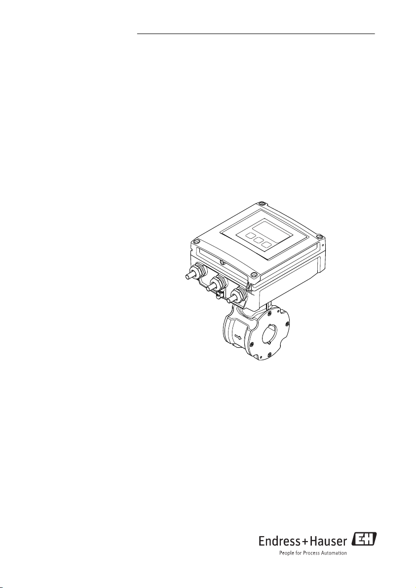
Proline Promag D 400
Electromagnetic flowmeter
These Instructions are Brief Operating Instructions; they are
not a substitute for the Operating Instructions pertaining to
the device.
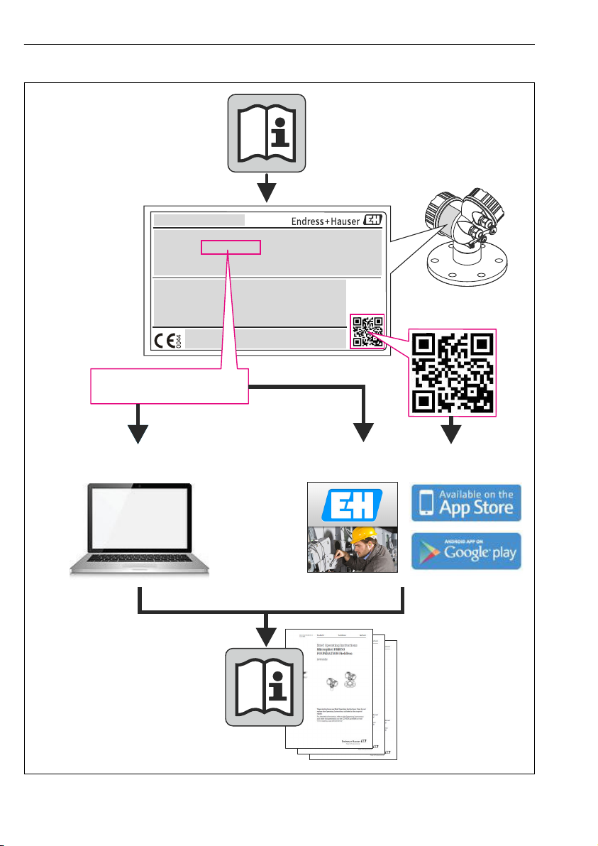
Detailed information about the device can be found in the
Operating Instructions and the other documentation:
• On the CD-ROM supplied (not included in the delivery for all
device versions).
• Available for all device versions via:
– Internet: www.endress.com/deviceviewer
– Smart phone/tablet: Endress+Hauser Operations App
Page 2
TAG No.: XXX000
Ser. No.: X000X000000
Order code 00X00-XXXX0XX0XXX
www.endress.com/deviceviewer Endress+Hauser Operations App
Serial number
Proline Promag D 400
2 Endress+Hauser
A0023555
Page 3

Proline Promag D 400 Table of contents
Table of contents
1 Document information ........................................................... 4
1.1 Symbols used ........................................................................ 4
2 Basic safety instructions ......................................................... 5
2.1 Requirements for the personnel ........................................................... 5
2.2 Designated use ....................................................................... 6
2.3 Workplace safety ...................................................................... 7
2.4 Operational safety ..................................................................... 7
2.5 Product safety ........................................................................ 7
2.6 IT security ........................................................................... 7
3 Product description .............................................................. 7
4 Incoming acceptance and product identification .................................. 8
4.1 Incoming acceptance ................................................................... 8
4.2 Product identification .................................................................. 9
5 Storage and transport ........................................................... 10
5.1 Storage conditions .................................................................... 10
5.2 Transporting the product ............................................................... 10
6 Installation ..................................................................... 12
6.1 Installation conditions ................................................................. 12
6.2 Mounting the measuring device .......................................................... 16
6.3 Post-installation check ................................................................. 24
7 Electrical connection ............................................................ 26
7.1 Connection conditions ................................................................. 26
7.2 Connecting the measuring device ......................................................... 33
7.3 Hardware settings .................................................................... 39
7.4 Ensuring the degree of protection ........................................................ 42
7.5 Post-connection check ................................................................. 42
8 Operation options .............................................................. 43
8.1 Structure and function of the operating menu ................................................ 43
8.2 Access to the operating menu via the local display ............................................ 44
8.3 Access to the operating menu via the Web browser ............................................ 48
8.4 Access to the operating menu via the operating tool ........................................... 51
9 System integration .............................................................. 52
9.1 Cyclic data transmission ............................................................... 52
10 Commissioning ................................................................. 56
10.1 Function check ...................................................................... 56
10.2 Switching on the measuring device ........................................................ 56
10.3 Configuring the device address via software ................................................. 56
10.4 Setting the operating language .......................................................... 57
10.5 Configuring the measuring device ........................................................ 57
10.6 Protecting settings from unauthorized access ................................................ 58
11 Diagnostic information ......................................................... 58
Endress+Hauser 3
Page 4
Document information Proline Promag D 400
DANGER
WARNING
CAUTION
NOTICE
1 Document information
1.1 Symbols used
1.1.1 Safety symbols
Symbol Meaning
DANGER!
This symbol alerts you to a dangerous situation. Failure to avoid this situation will result in
serious or fatal injury.
WARNING!
This symbol alerts you to a dangerous situation. Failure to avoid this situation can result in
serious or fatal injury.
CAUTION!
This symbol alerts you to a dangerous situation. Failure to avoid this situation can result in
minor or medium injury.
NOTE!
This symbol contains information on procedures and other facts which do not result in personal
injury.
1.1.2 Electrical symbols
Symbol Meaning Symbol Meaning
Direct current Alternating current
Direct current and alternating current Ground connection
Protective ground connection
A terminal which must be connected to
ground prior to establishing any other
connections.
A grounded terminal which, as far as
the operator is concerned, is grounded
via a grounding system.
Equipotential connection
A connection that has to be connected
to the plant grounding system: This
may be a potential equalization line or
a star grounding system depending on
national or company codes of practice.
1.1.3 Tool symbols
Symbol Meaning Symbol Meaning
Torx screwdriver Flat blade screwdriver
Phillips head screwdriver Allen key
Open-ended wrench
4 Endress+Hauser
Page 5
Proline Promag D 400 Basic safety instructions
,…,
,…,
-
.
1.1.4 Symbols for certain types of information
Symbol Meaning Symbol Meaning
Permitted
Procedures, processes or actions that
are permitted.
Forbidden
Procedures, processes or actions that
are forbidden.
Reference to documentation Reference to page
Preferred
Procedures, processes or actions that
are preferred.
Tip
Indicates additional information.
Reference to graphic
Result of a sequence of actions Visual inspection
Series of steps
1.1.5 Symbols in graphics
Symbol Meaning Symbol Meaning
1, 2, 3,... Item numbers
A, B, C, ... Views A-A, B-B, C-C, ... Sections
Hazardous area
Flow direction
Series of steps
Safe area (non-hazardous area)
2 Basic safety instructions
2.1 Requirements for the personnel
The personnel must fulfill the following requirements for its tasks:
Trained, qualified specialists must have a relevant qualification for this specific function
‣
and task
Are authorized by the plant owner/operator
‣
Are familiar with federal/national regulations
‣
Before beginning work, the specialist staff must have read and understood the instructions
‣
in the Operating Instructions and supplementary documentation as well as in the
certificates (depending on the application)
Following instructions and basic conditions
‣
Endress+Hauser 5
Page 6

Basic safety instructions Proline Promag D 400
2.2 Designated use
Application and media
The measuring device described in these Instructions is intended only for flow measurement
of liquids with a minimum conductivity of 5 μS/cm.
Depending on the version ordered, the measuring device can also measure potentially
explosive, flammable, poisonous and oxidizing media.
Measuring devices for use in hazardous areas, in hygienic applications or in applications
where there is an increased risk due to process pressure, are labeled accordingly on the
nameplate.
To ensure that the measuring device remains in proper condition for the operation time:
Only use the measuring device in full compliance with the data on the nameplate and the
‣
general conditions listed in the Operating Instructions and supplementary documentation.
Based on the nameplate, check whether the ordered device is permitted for the intended
‣
use in the hazardous area (e.g. explosion protection, pressure vessel safety).
Use the measuring device only for media against which the process-wetted materials are
‣
adequately resistant.
If the measuring device is not operated at atmospheric temperature, compliance with the
‣
relevant basic conditions specified in the associated device documentation is absolutely
essential.
Incorrect use
Non-designated use can compromise safety. The manufacturer is not liable for damage caused
by improper or non-designated use.
WARNING
L
Danger of breakage of the sensor due to corrosive or abrasive fluids!
Verify the compatibility of the process fluid with the sensor material.
‣
Ensure the resistance of all fluid-wetted materials in the process.
‣
Observe the specified pressure and temperature range.
‣
Verification for borderline cases:
For special fluids and fluids for cleaning, Endress+Hauser is glad to provide assistance in
‣
verifying the corrosion resistance of fluid-wetted materials, but does not accept any
warranty or liability as minute changes in the temperature, concentration or level of
contamination in the process can alter the corrosion resistance properties.
Residual risks
The external surface temperature of the housing can increase by max. 10 K due to the power
consumption of the electronic components. Hot process fluids passing through the measuring
device will further increase the surface temperature of the housing. The surface of the sensor,
in particular, can reach temperatures which are close to the fluid temperature.
Possible burn hazard due to fluid temperatures!
For elevated fluid temperature, ensure protection against contact to prevent burns.
‣
6 Endress+Hauser
Page 7

Proline Promag D 400 Product description
2.3 Workplace safety
For work on and with the device:
Wear the required personal protective equipment according to federal/national
‣
regulations.
For welding work on the piping:
Do not ground the welding unit via the measuring device.
‣
If working on and with the device with wet hands:
It is recommended to wear gloves on account of the higher risk of electric shock.
‣
2.4 Operational safety
Risk of injury.
Operate the device in proper technical condition and fail-safe condition only.
‣
The operator is responsible for interference-free operation of the device.
‣
Environmental requirements
If a plastic transmitter housing is permanently exposed to certain steam and air mixtures, this
can damage the housing.
If you are unsure, please contact your Endress+Hauser Sales Center for clarification.
‣
If used in an approval-related area, observe the information on the nameplate.
‣
2.5 Product safety
This measuring device is designed in accordance with good engineering practice to meet stateof-the-art safety requirements, has been tested, and left the factory in a condition in which it
is safe to operate.
It meets general safety standards and legal requirements. It also complies with the EC
directives listed in the device-specific EC Declaration of Conformity. Endress+Hauser confirms
this by affixing the CE mark to the device.
2.6 IT security
We only provide a warranty if the device is installed and used as described in the Operating
Instructions. The device is equipped with security mechanisms to protect it against any
inadvertent changes to the device settings.
IT security measures in line with operators' security standards and designed to provide
additional protection for the device and device data transfer must be implemented by the
operators themselves.
3 Product description
The device consists of a transmitter and a sensor.
Endress+Hauser 7
Page 8
Incoming acceptance and product identification Proline Promag D 400
1
+
2
1
+
2
Two device versions are available:
• Compact version - the transmitter and sensor form a mechanical unit.
• Remote version – the transmitter and sensor are mounted separately from one another.
For detailed information on the product description, see the Operating Instructions for
the device.
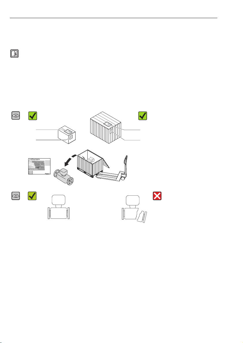
4 Incoming acceptance and product identification
4.1 Incoming acceptance
Are the order codes on the
delivery note (1) and the
product sticker (2) identical?
Are the goods undamaged?
8 Endress+Hauser
Page 9
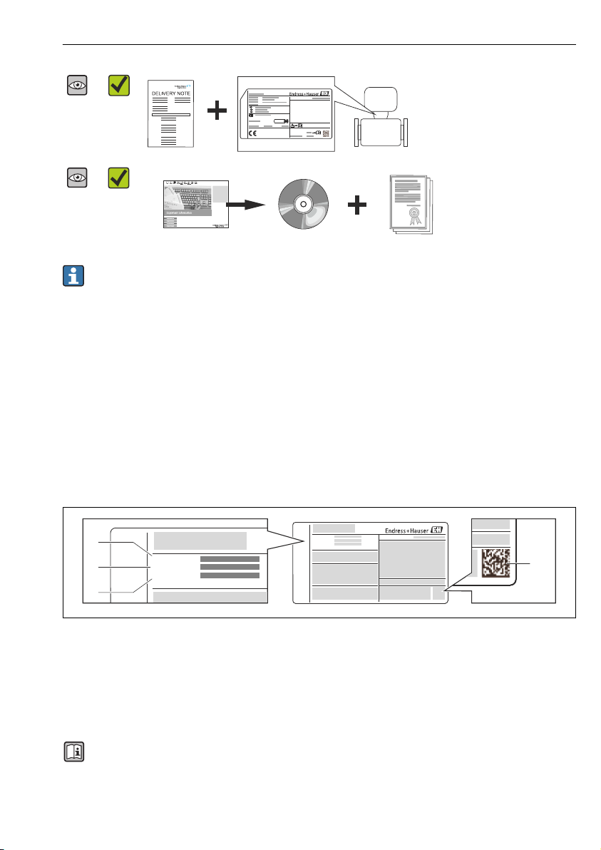
Proline Promag D 400 Incoming acceptance and product identification
Order code:
Ext. ord. cd.:
Ser. no.:
Order code:
Ext. ord. cd.:
Ser. no.:
1
2
3
4
Do the nameplate data match
the ordering information on
the delivery note?
Is the CD-ROM with the
Technical Documentation
(depends on device version)
and documents present?
• If one of the conditions is not satisfied, contact your Endress+Hauser Sales Center.
• Depending on the device version, the CD-ROM might not be part of the delivery! The
Technical Documentation is available via the Internet or via the Endress+Hauser
Operations App.
4.2 Product identification
The following options are available for identification of the measuring device:
• Nameplate specifications
• Order code with breakdown of the device features on the delivery note
• Enter serial numbers from nameplates in W@M Device Viewer
(www.endress.com/deviceviewer): All information about the measuring device is displayed.
• Enter the serial number from the nameplates into the Endress+Hauser Operations App or
scan the 2-D matrix code (QR code) on the nameplate with the Endress+Hauser Operations
App: all the information for the measuring device is displayed.
A0021952
1 Example of a nameplate
1 Order code
2 Serial number (Ser. no.)
3 Extended order code (Ext. ord. cd.)
4 2-D matrix code (QR code)
For detailed information on the breakdown of the specifications on the nameplate, see
the Operating Instructions for the device .
Endress+Hauser 9
Page 10
Storage and transport Proline Promag D 400
5 Storage and transport
5.1 Storage conditions
Observe the following notes for storage:
• Store in original packaging.
• Do not remove protective covers or protective caps installed on process connections.
• Protect from direct sunlight.
• Select a storage location where moisture cannot collect in the measuring device.
• Store in a dry and dust-free place.
• Do not store outdoors.
• Storage temperature→ 12
5.2 Transporting the product
Transport the measuring device to the measuring point in the original packaging.
A0015604
Do not remove protective covers or caps installed on process connections. They prevent
mechanical damage to the sealing surfaces and contamination in the measuring tube.
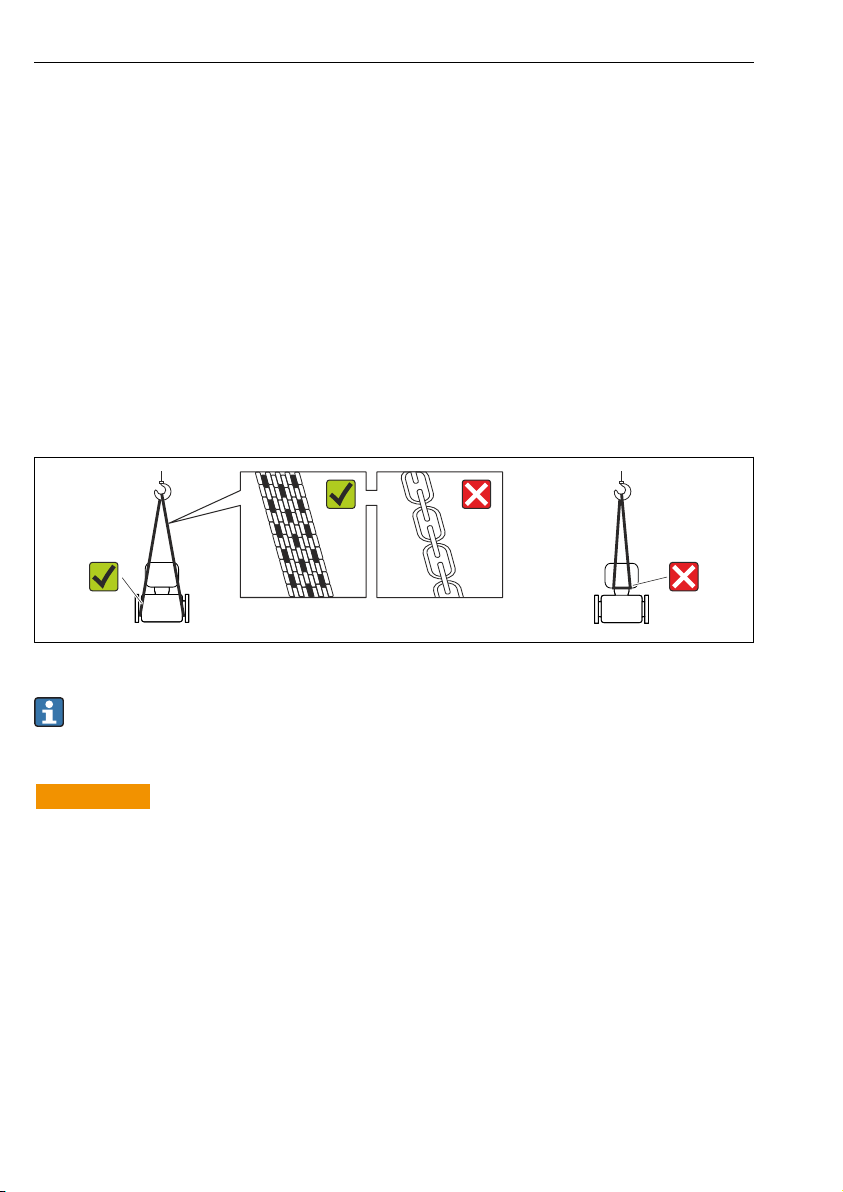
5.2.1 Measuring devices without lifting lugs
WARNING
L
Center of gravity of the measuring device is higher than the suspension points of the
webbing slings.
Risk of injury if the measuring device slips.
Secure the measuring device against slipping or turning.
‣
Observe the weight specified on the packaging (stick-on label).
‣
10 Endress+Hauser
Page 11
Proline Promag D 400 Storage and transport
A0015606
5.2.2 Measuring devices with lifting lugs
CAUTION
L
Special transportation instructions for devices with lifting lugs
Only use the lifting lugs fitted on the device or flanges to transport the device.
‣
The device must always be secured at two lifting lugs at least.
‣
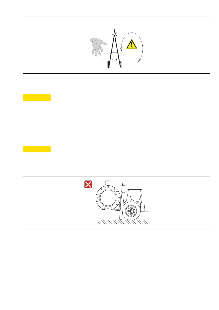
5.2.3 Transporting with a fork lift
If transporting in wood crates, the floor structure enables the crates to be lifted lengthwise or
at both sides using a forklift.
CAUTION
L
Risk of damaging the magnetic coil
If transporting by forklift, do not lift the sensor by the metal casing.
‣
This would buckle the casing and damage the internal magnetic coils.
‣
A0023726
Endress+Hauser 11
Page 12
Installation Proline Promag D 400
h
h
2
1
6 Installation
6.1 Installation conditions
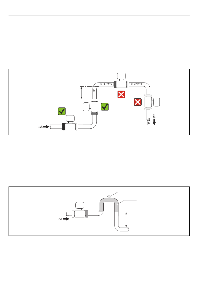
6.1.1 Mounting position
Mounting location
A0023343
h ≥ 2 × DN
Installation in down pipes
Install a siphon with a vent valve downstream of the sensor in down pipes whose length h ≥
5 m (16.4 ft). This precaution is to avoid low pressure and the consequent risk of damage to
the measuring tube. This measure also prevents the system losing prime.
A0017064
2 Installation in a down pipe
1 Vent valve
2 Pipe siphon
h Length of down pipe
12 Endress+Hauser
Page 13
Proline Promag D 400 Installation
³ 5 × DN
³ 2 × DN
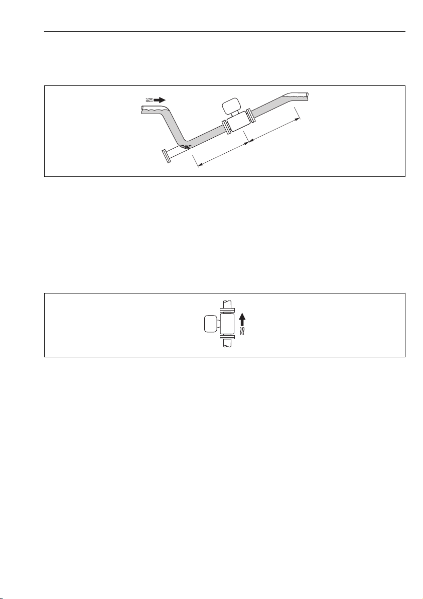
Installation in partially filled pipes
A partially filled pipe with a gradient necessitates a drain-type configuration.
A0017063
Orientation
The direction of the arrow on the sensor nameplate helps you to install the sensor according
to the flow direction.
An optimum orientation position helps avoid gas and air accumulations and deposits in the
measuring tube.
Vertical
A0015591
Optimum for self-emptying pipe systems.
Endress+Hauser 13
Page 14
Installation Proline Promag D 400
1 1
5 × DN≥
2 × DN≥
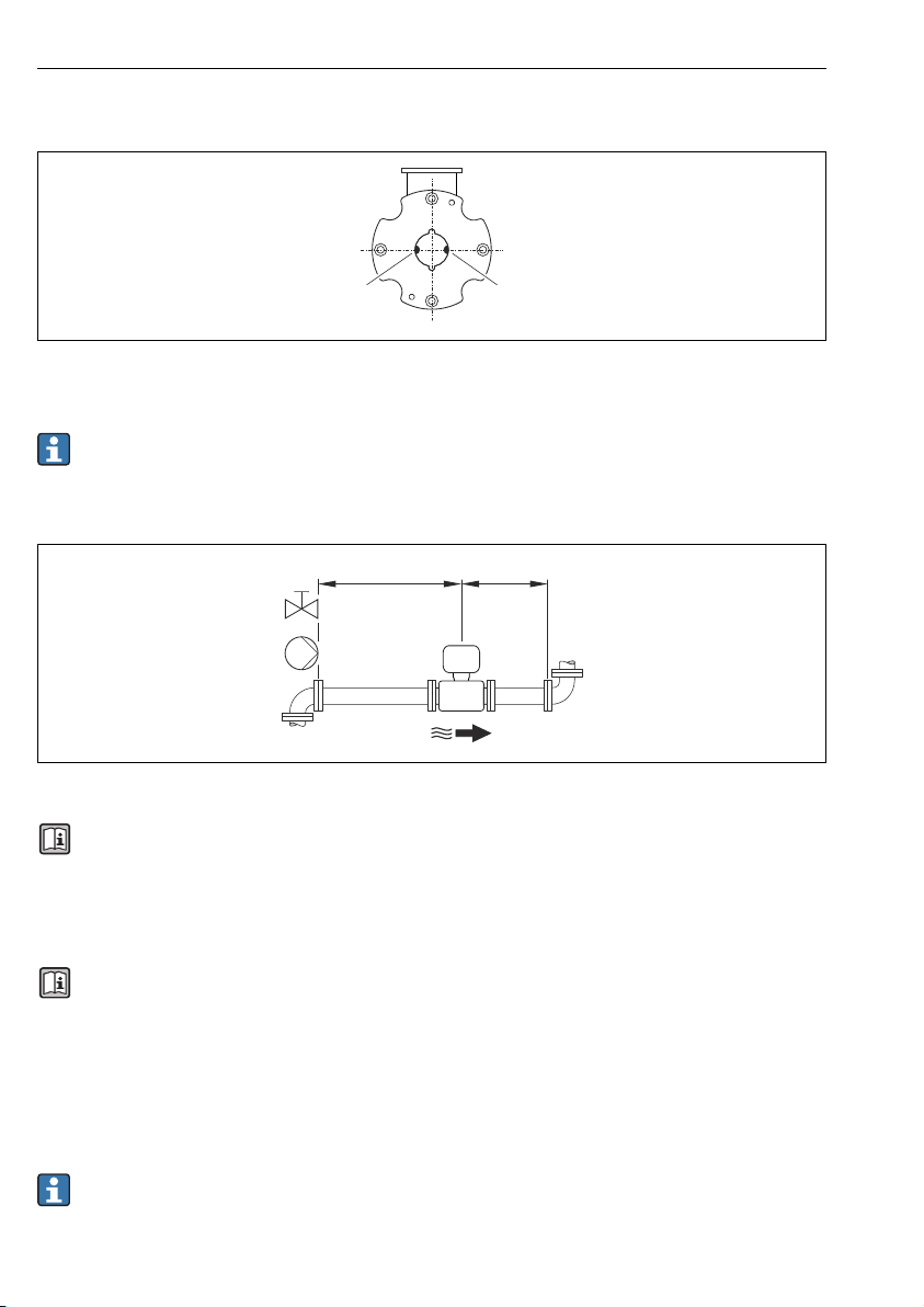
Horizontal
A0017195
1 Measuring electrodes for signal detection
The measuring electrode plane must be horizontal. This prevents brief insulation of the
two measuring electrodes by entrained air bubbles.
Inlet and outlet runs
For the dimensions and installation lengths of the device, see the "Technical Information"
document, "Mechanical construction" section
6.1.2 Requirements from environment and process
Ambient temperature range
For detailed information on the ambient temperature range, see the Operating
Instructions for the device.
If operating outdoors:
• Install the measuring device in a shady location.
• Avoid direct sunlight, particularly in warm climatic regions.
• Avoid direct exposure to weather conditions.
• Protect the display against impact.
• Protect the display from abrasion by sand in desert areas.
A display protector can be ordered from Endress+Hauser: "Accessories" section
14 Endress+Hauser
A0016275
Page 15
Proline Promag D 400 Installation
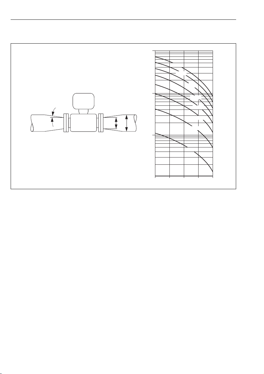
L
System pressure
A0015594
Furthermore, install pulse dampers if reciprocating, diaphragm or peristaltic pumps are
used.
Vibrations
It is recommended to mount the sensor and transmitter separately.
A0016266
3 Measures to avoid device vibrations (L > 10 m (33 ft))
Endress+Hauser 15
Page 16
Installation Proline Promag D 400
100
10
0.5
d / D
[mbar]
0.6 0.7 0.8 0.9
1 m/s
2 m/s
3 m/s
4 m/s
5 m/s
6 m/s
7 m/s
8 m/s
1
D
d
max. 8°
Adapters
A0016359
6.1.3 Special mounting instructions
Display protection
To ensure that the optional display protection can be easily opened, maintain the following
‣
minimum head clearance: 350 mm (13.8 in)
6.2 Mounting the measuring device
6.2.1 Required tools
For transmitter
• Torque wrench
• For wall mounting:
Open-ended wrench for hexagonal screw max. M5
• For pipe mounting:
– Open-ended wrench AF 8
– Phillips head screwdriver PH 2
• For turning the transmitter housing (compact version):
– Phillips head screwdriver PH 2
– Torx screwdriver TX 20
– Open-ended wrench AF 7
16 Endress+Hauser
Page 17
Proline Promag D 400 Installation
5
1
2
3
4
For sensor
For flanges and other process connections:
• Screws, nuts, seals etc. are not included in the scope of supply and must be provided by the
customer.
• Appropriate mounting tools
6.2.2 Preparing the measuring device
1. Remove all remaining transport packaging.
2. Remove any protective covers or protective caps present from the sensor.
3. Remove stick-on label on the electronics compartment cover.
6.2.3 Mounting the sensor
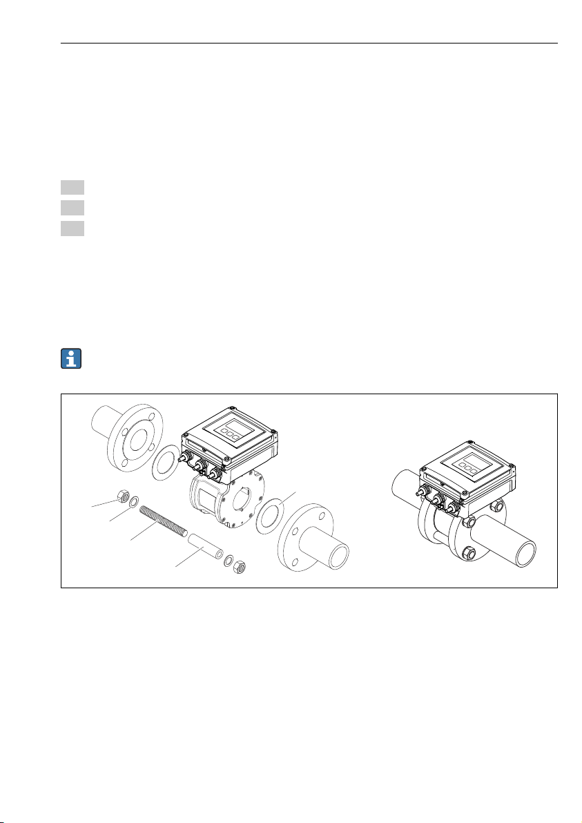
Mounting kit
The sensor is installed between the pipe flanges using a mounting kit. The device is centered
using the recesses on the sensor. Centering sleeves are also provided depending on the flange
standard or the diameter of the pitch circle.
A mounting kit – consisting of mounting bolts, seals, nuts and washers – can be ordered
separately (see "Accessories" section ).
A0018060
4 Mounting the sensor
1 Nut
2 Washer
3 Mounting bolts
4 Centering sleeve
5 Seal
Endress+Hauser 17
Page 18
Installation Proline Promag D 400
1
1
1
1
1
1
1
1
1
1
1
1
2
2
2 2
3
3
3
3
3
3
3
3
1
1
1
1
1
1
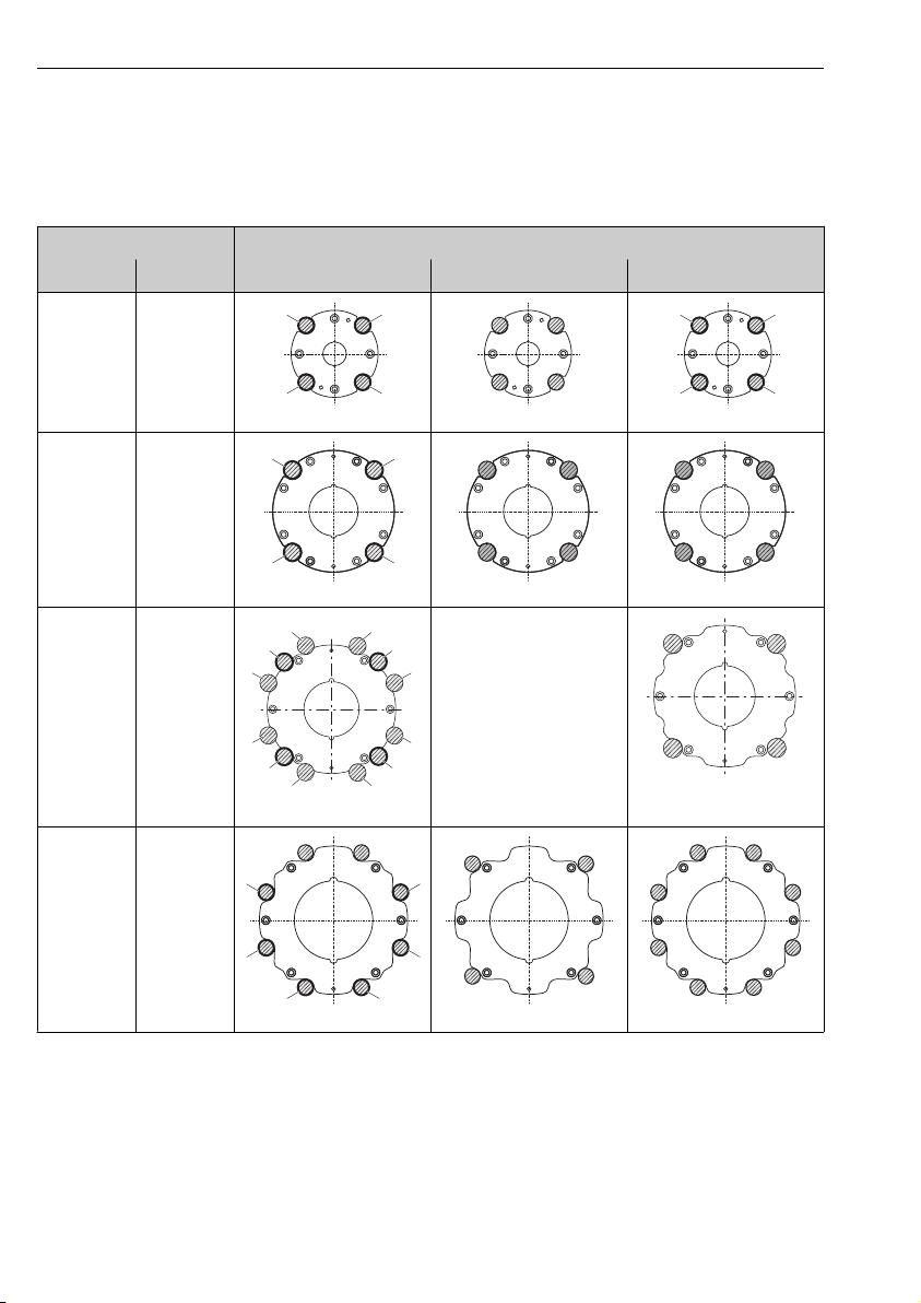
Arranging the mounting bolts and centering sleeves
The device is centered using recesses on the sensor. The arrangement of the mounting bolts
and the use of the centering sleeves supplied depend on the nominal diameter, the flange
standard and the diameter of the pitch circle.
Nominal diameter Process connection
[mm] [in]5 EN 1092-1 (DIN 2501) ASME B16.5 JIS B2220
25…40 1…1 ½
50 2
65 2 ½
80 3
A0010896 A0010824
A0010897 A0010825 A0010825
–
A0012170
A0010898 A0010827 A0010826
A0010896
A0012171
18 Endress+Hauser
Page 19

Proline Promag D 400 Installation
1
1
1
1
1
1
1
1
1
1
1
1
1
1
1
1
Nominal diameter Process connection
[mm] [in]5 EN 1092-1 (DIN 2501) ASME B16.5 JIS B2220
100 4
A0012168
1 = Mounting bolts with centering sleeves
2 = EN (DIN) flange: 4-hole → with centering sleeves
3 = EN (DIN) flange: 8-hole → without centering sleeves
A0012168
A0012169
Mounting the seals
CAUTION
L
An electrically conductive layer could form on the inside of the measuring tube!
Risk of measuring signal short circuit.
Do not use electrically conductive sealing compounds such as graphite.
‣
Comply with the following instructions when installing seals:
• Make sure that the seals do not protrude into the piping cross-section.
• For DIN flanges: only use seals according to DIN EN 1514-1.
• Use seals with a hardness rating of 70° Shore.
Mounting the ground cable/ground disks
Comply with the information on potential equalization and detailed mounting instructions for
the use of ground cables/ground disks → 38.
Screw tightening torques
For detailed information on the screw tightening torques, see the "Mounting the sensor"
section of the Operating Instructions for the device
6.2.4 Mounting the transmitter of the remote version
CAUTION
L
Ambient temperature too high!
Danger of electronics overheating and housing deformation.
Do not exceed the permitted maximum ambient temperature → 14.
‣
If operating outdoors: Avoid direct sunlight and exposure to weathering, particularly in
‣
warm climatic regions.
Endress+Hauser 19
Page 20

Installation Proline Promag D 400
149 (5.85)
210.5 (8.29)
=
5.8 (0.23)
17 (0.67) =
14 (0.55)
5.8 (0.23)
CAUTION
L
Excessive force can damage the housing!
Avoid excessive mechanical stress.
‣
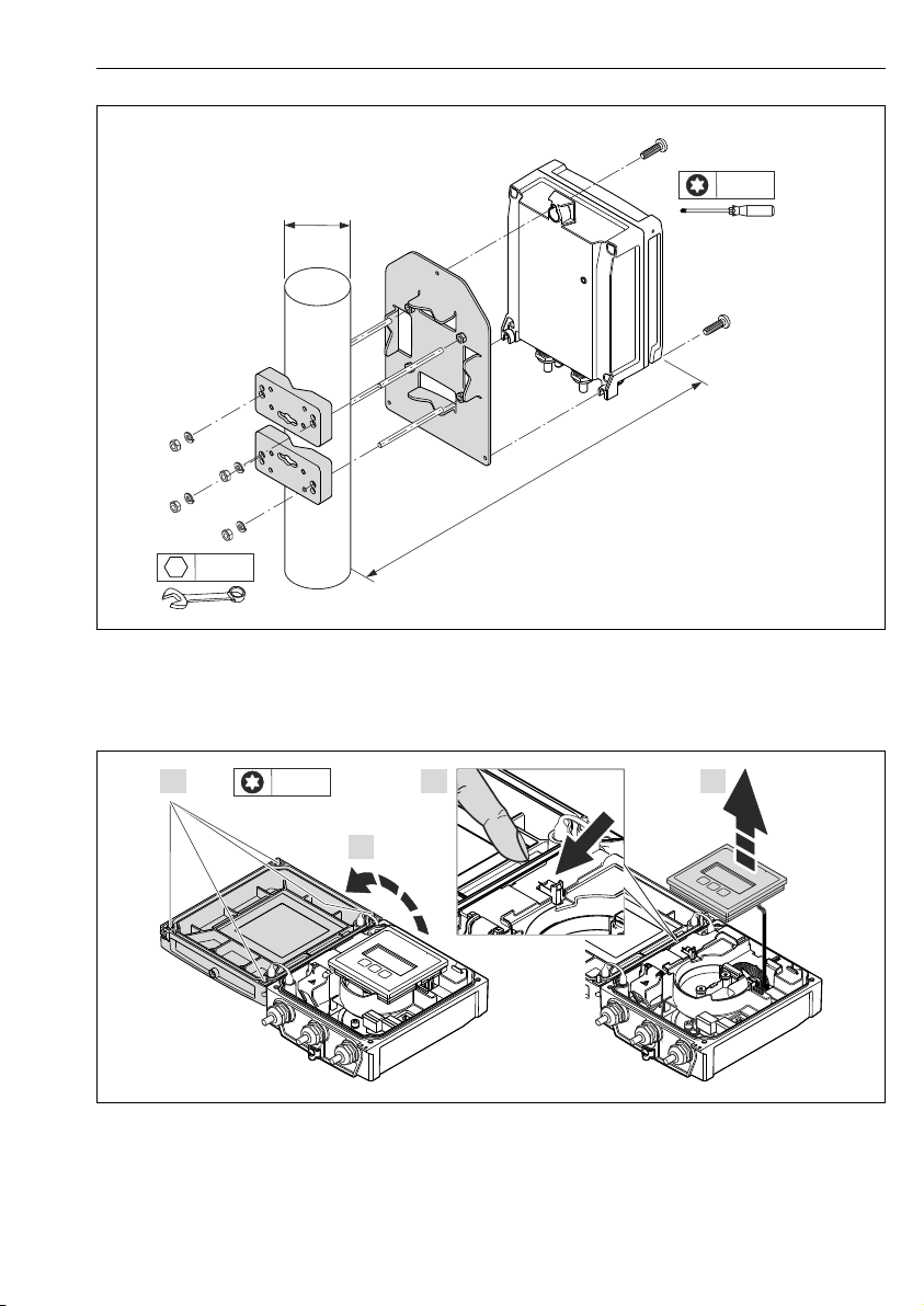
Wall mounting
A0020523
5 Engineering unit mm (in)
Post mounting
WARNING
L
Excessive tightening torque applied to the fixing screws on plastic housing!
Risk of damaging the plastic transmitter.
Tighten the fixing screws as per the tightening torque: 2 Nm (1.5 lbf ft)
‣
20 Endress+Hauser
Page 21
Proline Promag D 400 Installation
ø 20…70
( 0.79…2.75)ø
~ ~ 4.0)102 (
4 x
SW 8
3 x
TX 25
TX 20
4 x
1.
2.
PUSHTO
REMOVE
PUSH TO
REMOVE
3.
4.
A0020705
6 Engineering unit mm (in)
6.2.5 Turning the transmitter housing
Endress+Hauser 21
A0021602
Page 22

Installation Proline Promag D 400
PUSHTO
REMOVE
3 mm
2 x
5.
6.
PUSHTO
REMOVE
PUSHTO
REMOVE
TX 20
5 x
7.
PUSHTO
REMOVE
8.
PUSHTO
REMOVE
9.
10.
4 mm
4 x
A0021603
A0021830
A0021831
22 Endress+Hauser
Page 23

Proline Promag D 400 Installation
11.
12.
A0021832
Reassembling the transmitter housing
WARNING
L
Excessive tightening torque applied to the fixing screws!
Damage to the transmitter.
When reassembling, tighten the fixing screws as per the tightening torque:
‣
Step
(see graphics)
1 Housing cover 2.5 Nm (1.8 lbf ft) 1 Nm (0.7 lbf ft)
5 Smart sensor electronics module 0.6 Nm (0.4 lbf ft)
7 Main electronics module 1.5 Nm (1.1 lbf ft)
10 Transmitter housing 5.5 Nm (4.1 lbf ft)
Fixing screw Tightening torques for housing made of:
Aluminum Plastic
NOTICE
Plug of the smart sensor electronics module connected incorrectly!
No measuring signal is output.
Plug in the plug of the smart sensor electronics module as per the coding.
‣
NOTICE
Incorrect routing of the connecting cables between the sensor and transmitter in the
transmitter housing!
This can interfere with the measuring signal.
Route the connecting cables directly at the level of the plugs.
‣
Reverse the procedure to reassemble the measuring device.
‣
Endress+Hauser 23
Page 24

Installation Proline Promag D 400
TX 20
4 x
1.
2.
PUSHTO
REMOVE
PUSH TO
REMOVE
3.
4.
6.2.6 Turning the display module
A0021617
Reassembling the transmitter housing
WARNING
L
Excessive tightening torque applied to the fixing screws!
Damage to the transmitter.
When reassembling, tighten the fixing screws as per the tightening torque:
‣
Step
(see graphic)
1 Housing cover 2.5 Nm (1.8 lbf ft) 1 Nm (0.7 lbf ft)
Reverse the procedure to reassemble the measuring device.
‣
Fixing screw Tightening torque for housing made of:
Aluminum Plastic
6.3 Post-installation check
Is the device undamaged (visual inspection)?
Does the measuring device conform to the measuring point specifications?
For example:
• Process temperature
• Process pressure (refer to the section on "Pressure-temperature ratings" in the "Technical Information"
• Ambient temperature
• Measuring range
Has the correct orientation for the sensor been selected ?
• According to sensor type
• According to medium temperature
• According to medium properties (outgassing, with entrained solids)
Does the arrow on the sensor nameplate match the direction of flow of the fluid through the piping ?
Are the measuring point identification and labeling correct (visual inspection)?
24 Endress+Hauser
document on the CD-ROM provided)
Page 25

Proline Promag D 400 Installation
Is the device adequately protected from precipitation and direct sunlight?
Have the fixing screws been tightened with the correct tightening torque?
Endress+Hauser 25
Page 26

Electrical connection Proline Promag D 400
7 Electrical connection
The measuring device does not have an internal circuit breaker. For this reason, assign
the measuring device a switch or power-circuit breaker so that the power supply line can
be easily disconnected from the mains.
7.1 Connection conditions
7.1.1 Required tools
• Torque wrench
• For cable entries: Use corresponding tools
• For housing cover: Torx screwdriver or flat-blade screwdriver
• Wire stripper
• When using stranded cables: crimping tool for ferrule
7.1.2 Requirements for connecting cable
The connecting cables provided by the customer must fulfill the following requirements.
Electrical safety
In accordance with applicable federal/national regulations.
Permitted temperature range
• –40 °C (–40 °F) to +80 °C (+176 °F)
• Minimum requirement: cable temperature range ≥ ambient temperature +20 K
Power supply cable
Standard installation cable is sufficient.
Signal cable
Current output
• For 0-20 mA and 4-20 mA: standard installation cable is sufficient.
• For 4-20 mA HART: Shielded cable recommended. Observe grounding concept of the plant.
Pulse/frequency/switch output
Standard installation cable is sufficient.
Status input
Standard installation cable is sufficient.
PROFIBUS DP
The IEC 61158 standard specifies two types of cable (A and B) for the bus line which can be
used for every transmission rate. Cable type A is recommended.
For detailed information about the specification of the connecting cable, see the
Operating Instructions for the device.
26 Endress+Hauser
Page 27

Proline Promag D 400 Electrical connection
Modbus RS485
The EIA/TIA-485 standard specifies two types of cable (A and B) for the bus line which can be
used for every transmission rate. Cable type A is recommended.
For detailed information about the specification of the connecting cable, see the
Operating Instructions for the device.
EtherNet/IP
The standard ANSI/TIA/EIA-568-B.2 Annex specifies CAT 5 as the minimum category for a
cable used for EtherNet/IP. CAT 5e and CAT 6 are recommended.
For more information on planning and installing EtherNet/IP networks, please refer to
the "Media Planning and Installation Manual. EtherNet/IP" of the ODVA Organization.
Connecting cable for remote version
The remote version is connected via an electrode cable and a coil current cable.
For detailed information about the specification of the connecting cables, see the
Operating Instructions for the device.
Operation in zones of severe electrical interference
Grounding is by means of the ground terminal provided for the purpose inside the connection
housing. The stripped and twisted lengths of cable shield to the ground terminal must be as
short as possible.
Cable diameter
• Cable glands supplied:
– For standard cable: M20 × 1.5 with cable 6 to 12 mm (0.24 to 0.47 in)
– For reinforced cable: M20 × 1.5 with cable 9.5 to 16 mm (0.37 to 0.63 in)
• (Plug-in) spring terminals for wire cross-sections 0.5 to 2.5 mm2 (20 to 14 AWG)
7.1.3 Terminal assignment
Transmitter
Supply voltage
Order code for "Power supply" Terminal numbers
1 (L+/L) 2 (L-/N)
Option L
(wide range power unit)
Endress+Hauser 27
AC100 to 240 V
AC/DC24 V
Page 28

Electrical connection Proline Promag D 400
Signal transmission 0-20 mA/4-20 mA HART with additional outputs and inputs
Order code for
"Output" and "Input"
26 (+) 27 (-) 24 (+) 25 (-) 22 (+) 23 (-) 20 (+) 21 (-)
Option H • 4-20 mA HART
• 0-20 mA
Option I • 4-20 mA HART
• 0-20 mA
Output 1 Output 2 Output 3 Input
Pulse/frequency
(active)
(active)
Pulse/frequency/
(active)
(active)
Terminal numbers
output
(passive)
switch output
(passive)
Switch output
(passive)
Pulse/frequency/
switch output
(passive)
-
Status input
PROFIBUS DP signal transmission
Order code for "Output" and "Input" Terminal numbers
26 (RxD/TxD-P) 27 (RxD/TxD-N)
Option L B A
Order code for "Output":
Option L: PROFIBUS DP, for use in non-hazardous areas and Zone 2/div. 2
Signal transmission Modbus RS485
Order code for "Output" and "Input" Terminal numbers
26 (+) 27 (-)
Option M A B
EtherNet/IP signal transmission
Order code for "Output" Connection via
Option N EtherNet/IP connector
28 Endress+Hauser
Page 29

Proline Promag D 400 Electrical connection
E1
E2
GND
S1
E1
E2
S2
GND
5
7
4
37
42 41
657
8437 36
n.c. n.c.
21
1
2
42 41
A
B
3
2
4
1
Remote version
A0020539
7 Remote version terminal assignment
A Transmitter wall-mount housing
B Sensor connection housing
1 Electrode cable
2 Coil current cable
n.c. Not connected, insulated cable shields
Terminal No. and cable colors: 6/5 = brown; 7/8 = white; 4 = green
7.1.4 Pin assignment, device plug
EtherNet/IP
Device plug for signal transmission (device side)
Pin Assignment Coding Plug/socket
1 + Tx D Socket
A0016812
Endress+Hauser 29
2 + Rx
3 - Tx
4 - Rx
Page 30

Electrical connection Proline Promag D 400
7.1.5 Shielding and grounding
Modbus
The shielding and grounding concept requires compliance with the following:
• Electromagnetic compatibility (EMC)
• Explosion protection
• Personal protection equipment
• National installation regulations and guidelines
• Observe cable specification → 26.
• Keep the stripped and twisted lengths of cable shield to the ground terminal as short as
possible.
• Seamless cable shielding.
Grounding of the cable shield
To comply with EMC requirements:
• Ensure the cable shield is grounded to the potential matching line at multiple points.
• Connect every local ground terminal to the potential matching line.
NOTICE
In systems without potential matching, the multiple grounding of the cable shield causes
mains frequency equalizing currents!
Damage to the bus cable shield.
Only ground the bus cable shield to either the local ground or the protective ground at one
‣
end.
PROFIBUS DP
Optimum electromagnetic compatibility (EMC) of the fieldbus system can only be guaranteed
if the system components and, in particular, the lines are shielded and the shield forms as
complete a cover as possible. A shield coverage of 90% is ideal.
• To ensure an optimum EMC protective effect, connect the shield as often as possible to the
reference ground.
• For reasons of explosion protection, you should refrain from grounding however.
To comply with both requirements, the fieldbus system allows three different types of
shielding:
• Shielding at both ends.
• Shielding at one end on the feed side with capacitance termination at the field device.
• Shielding at one end on the feed side.
Experience shows that the best results with regard to EMC are achieved in most cases in
installations with one-sided shielding on the feed side (without capacitance termination at
the field device). Appropriate measures with regard to input wiring must be taken to allow
unrestricted operation when EMC interference is present. These measures have been taken
into account for this device. Operation in the event of disturbance variables as per NAMUR
NE21 is thus guaranteed.
Where applicable, national installation regulations and guidelines must be observed during
the installation!
30 Endress+Hauser
Page 31

Proline Promag D 400 Electrical connection
21 3
+
-
+
-
+
-
4
5
5
78
6
6
6
6
6
6
.
-
Where there are large differences in potential between the individual grounding points, only
one point of the shielding is connected directly with the reference ground. In systems without
potential equalization, therefore, cable shielding of fieldbus systems should only be grounded
on one side, for example at the fieldbus supply unit or at safety barriers.
NOTICE
In systems without potential matching, the multiple grounding of the cable shield causes
mains frequency equalizing currents!
Damage to the bus cable shield.
Only ground the bus cable shield to either the local ground or the protective ground at one
‣
end. Insulate the shield that is not connected.
1 Controller (e.g. PLC)
2 Segment coupler PROFIBUS DP/PA
3 Cable shield
4 T-box
5 Measuring device
6 Local grounding
7 Bus terminator
8 Potential matching line
A0019004
7.1.6 Preparing the measuring device
1. Remove dummy plug if present.
Endress+Hauser 31
Page 32

Electrical connection Proline Promag D 400
A
80 (3.15)
50 (1.97)
17 (0.67)
8 (0.31)
100 (3.94)*
B
GND
1
2
1
2
1
2
2
A
90 (3.54)*
70 (2.76)
50 (1.97)
10 (0.39)
8 (0.31)
B
1
2. If measuring device is delivered with cable glands:
Observe cable specification → 26.
7.1.7 Preparing the connecting cable for the remote version
When terminating the connecting cable, pay attention to the following points:
• In the case of electrode cables, make sure that the ferrules do not touch the core shields on
the sensor side. Minimum distance = 1 mm (exception: green “GND” cable)
• In the case of coil current cables, insulate one core of the three-core wire at the level of the
core reinforcement. You only require two cores for the connection.
• Fit the fine-wire cores with ferrules.
Transmitter
Electrode cable Coil current cable
9 Engineering unit mm (in)
A0021324
8 Engineering unit mm (in)
A = Termination of the cables
B = Termination of the fine-wire cores with ferrules
1 = Red ferrules, 1.0 mm (0.04 in)
2 = White ferrules, 0.5 mm (0.02 in)
* = Stripping only for reinforced cables
32 Endress+Hauser
A0021325
Page 33

Proline Promag D 400 Electrical connection
A
80 (3.15)
50 (1.97)
6 (0.24)
170 (6.69)*
20 (0.79)*
18.5 (0.73)
B
GND
³1 (0.04)
1
2
2
2
1
A
70 (2.76)
50 (1.97)
10 (0.39)
8 (0.31)
160 (6.30)*20 (0.79)*
B
1
1
1
Sensor
Electrode cable Coil current cable
A0016489
A0016488
A = Termination of the cables
B = Termination of the fine-wire cores with ferrules
1 = Red ferrules, 1.0 mm (0.04 in)
2 = White ferrules, 0.5 mm (0.02 in)
* = Stripping only for reinforced cables
7.2 Connecting the measuring device
WARNING
L
Risk of electric shock! Components carry dangerous voltages!
Have electrical connection work carried out by correspondingly trained specialists only.
‣
Observe applicable federal/national installation codes and regulations.
‣
Comply with local workplace safety regulations.
‣
Observe grounding concept of the plant.
‣
Never mount or wire the measuring device while it is connected to the supply voltage.
‣
Before the supply voltage is applied, connect the protective ground to the measuring
‣
device.
Endress+Hauser 33
Page 34

Electrical connection Proline Promag D 400
1.
2.
4.
3.
6
5 7
8 4 37 36 42 41
S1
E1
E2
S2
GND
E
S
TX 20
4 x
7.2.1 Connecting the remote version
WARNING
L
Risk of damaging the electronic components!
Ground the remote version: connect the sensor and transmitter to the same potential
‣
equalization.
Only connect the sensor to a transmitter with the same serial number.
‣
Ground the connection housing of the sensor via the external screw terminal.
‣
The following procedure (in the action sequence given) is recommended for the remote
version:
1. Mount the sensor and transmitter.
2. Connect the connecting cable.
3. Connect the transmitter.
10 Transmitter: main electronics module with terminals
34 Endress+Hauser
A0017445
Page 35

Proline Promag D 400 Electrical connection
3.
5 7
4
37 42
41
E1
E2
GND
E
A0017446
11 Sensor: connection module
7.2.2 Connecting the transmitter
WARNING
L
Housing degree of protection may be voided due to insufficient sealing of the housing.
Screw in the screw without using any lubricant. The threads on the cover are coated with a
‣
dry lubricant.
Tightening torques for plastic housing
Housing cover fixing screw 1.3 Nm
Cable entry 4.5 to 5 Nm
Ground terminal 2.5 Nm
Endress+Hauser 35
Page 36

Electrical connection Proline Promag D 400
TX 20
4 x
1.
2.
3.
26
27
24
25
23 20
21
22
+ - + -
+ - + -
1
2
L+/L
L-/N
6.
4.
5.
10 (0.4)
Supply voltage connection, 0-20 mA/4-20 mA HART and additional outputs/inputs
A0017268
Connect the cable in accordance with the terminal assignment → 28. For supply
‣
voltage: open the shock protection cover.
For HART communication: When connecting the cable shielding to the ground terminal,
observe the grounding concept of the facility.
36 Endress+Hauser
Page 37

Proline Promag D 400 Electrical connection
PH 2
4 x
1.
2.
3.
4.
5.
26
27
1
2
L+/L
L-/N
B
A
6.
10 (0.4)
Connecting the supply voltage and PROFIBUS DP
A0023164
Connect the cable in accordance with the terminal assignment → 28. For supply
‣
voltage: open the shock protection cover.
Endress+Hauser 37
Page 38

Electrical connection Proline Promag D 400
PH 2
4 x
1.
2.
3.
4.
5.
10 (0.4)
1
2
L+/L
L-/N
6.
Connecting the supply voltage and EtherNet/IP
A0021356
Connect the cable in accordance with the terminal assignment → 28. For supply
‣
voltage: open the shock protection cover.
7.2.3 Ensuring potential equalization
CAUTION
L
Electrode damage can result in the complete failure of the device!
Make sure that the fluid and sensor have the same electrical potential.
‣
Pay attention to internal grounding concepts in the company.
‣
Pay attention to the pipe material or grounding.
‣
Connection examples for standard situations
Metal, grounded pipe
This connection method also applies:
• For plastic pipes
• For pipes with insulating liner
38 Endress+Hauser
Page 39

Proline Promag D 400 Electrical connection
A0017516
Connection example in special situations
For detailed information on special cases, see the Operating Instructions for the device.
• Unlined and ungrounded metal pipe
• Plastic pipe or pipe with insulating liner
• Pipe with a cathodic protection unit
7.3 Hardware settings
7.3.1 Setting the device address
EtherNet/IP
The IP address of the measuring device can be configured for the network via DIP switches.
Addressing data
IP address and configuration options
1st octet 2nd octet 3rd octet 4th octet
192. 168. 1. XXX
↓ ↓
Can only be configured via software addressing Can be configured via
IP address range 1 to 254 (4th octet)
IP address broadcast 255
Addressing mode ex works Software addressing; all DIP switches for hardware addressing are set to OFF.
IP address ex works DHCP server active
software addressing
and hardware
addressing
For device addressing via software → 56
Endress+Hauser 39
Page 40

Electrical connection Proline Promag D 400
1
2
3
4
1
2
3
4
1
2
ON OFF
Default Ethernet network settings
IP 192.168.1.212
Write protection
128
64
32
16
8
4
2
1
IP Address
setting
(last octet)
1
2
3
4
1
2
3
4
1
2
ON OFF
Not used
Write protection
SW
64
32
16
8
4
2
1
PROFIBUS
address
Setting the address
A0021322
Set the desired IP address using the corresponding DIP switches on the I/O electronics
‣
module.
Hardware addressing with the configured IP address is enabled after 10 s.
PROFIBUS DP
The address must always be configured for a PROFIBUS DP/PA device. The valid address
range is between 1 and 126. In a PROFIBUS DP/PA network, each address can only be
assigned once. If an address is not configured correctly, the device is not recognized by the
master. All measuring devices are delivered from the factory with the device address 126 and
with the software addressing method.
Setting the address
12 Addressing using DIP switches on the I/O electronics module
1. Disable software addressing (OFF) via the top DIP switch 4 (SW).
40 Endress+Hauser
A0023061
Page 41

Proline Promag D 400 Electrical connection
OFF
ON
1 2 3
4
Bus polar.
Bus term.
Bus polar.
Not used
390 Ω
DIP 1
5V
26
27
220 Ω
DIP 2
0V
390 Ω
DIP 3
2. Set the desired device address via the corresponding DIP switches.
Example → 12, 40: 1 + 16 + 32 = device address 49
The device demands rebooting after 10 s. After rebooting, hardware addressing is
enabled with the configured IP address.
7.3.2 Enabling the terminating resistor
PROFIBUS DP
To avoid incorrect communication transmission caused by impedance mismatch, terminate
the PROFIBUS DP cable correctly at the start and end of the bus segment.
• If the device is operated with a baud rate of 1.5 MBaud and under:
For the last transmitter on the bus, terminate via DIP switch 2 (bus termination) and DIP
switch 1 and 3 (bus polarization). Setting: ON – ON – ON → 13, 41.
• For baud rates > 1.5 MBaud:
Due to the capacitance load of the user and the line reflections generated as a result, ensure
that an external bus terminator is used.
It is generally advisable to use an external bus terminator as the entire segment can fail
if a device that is terminated internally is defective.
13 Termination using DIP switches on the I/O electronics module (for baud rates < 1.5 MBaud)
Modbus RS485
To avoid incorrect communication transmission caused by impedance mismatch, terminate
the Modbus RS485 cable correctly at the start and end of the bus segment.
Endress+Hauser 41
A0023063
Page 42

Electrical connection Proline Promag D 400
OFF
ON
1 2 3
4
Bus polar.
Bus term.
Bus polar.
Not used
390 Ω
DIP 1
5V
26
27
220 Ω
DIP 2
0V
390 Ω
DIP 3
A0023063
14 Terminating resistor can be enabled via DIP switch on the main electronics module
7.4 Ensuring the degree of protection
7.4.1 Degree of protection IP66/67, Type 4X enclosure
The measuring device fulfills all the requirements for the IP66/67 degree of protection, Type
4X enclosure.
To guarantee IP66/67 degree of protection, Type 4X enclosure, carry out the following steps
after the electrical connection:
1. Check that the housing seals are clean and fitted correctly. Dry, clean or replace the
seals if necessary.
2. Tighten all housing screws and screw covers.
3. Firmly tighten the cable glands.
4. To ensure that moisture does not enter the cable entry, route the cable so that it loops
down before the cable entry ("water trap").
5. Insert dummy plugs into unused cable entries.
7.5 Post-connection check
Are cables or the device undamaged (visual inspection)?
Do the cables comply with the requirements → 26?
42 Endress+Hauser
A0013960
Page 43

Proline Promag D 400 Operation options
!
Expert
Operating menu for experts
Language
Operation
Setup
Diagnostics
Operating menu for operators and maintenances
Operator
Maintenance
task-oriented
function-oriented
Expert
Do the cables have adequate strain relief?
Are all the cable glands installed, firmly tightened and leak-tight? Cable run with "water trap" → 42 ?
Only for remote version: is the sensor connected to the right transmitter?
Check the serial number on the nameplate of the sensor and transmitter.
Does the supply voltage match the specifications on the transmitter nameplate ?
Is the terminal assignment correct ?
If supply voltage is present, do values appear on the display module?
Is the potential equalization established correctly → 38?
Are all housing covers installed and the screws tightened with the correct tightening torque?
8 Operation options
8.1 Structure and function of the operating menu
8.1.1 Structure of the operating menu
15 Schematic structure of the operating menu
8.1.2 Operating philosophy
The individual parts of the operating menu are assigned to certain user roles (operator,
A0014058-EN
maintenance etc.). Each user role contains typical tasks within the device lifecycle.
For detailed information on the operating philosophy, see the Operating Instructions for
the device.
Endress+Hauser 43
Page 44

Operation options Proline Promag D 400
5
4
ABC_
DEFG
User
HIJK
LMNO
PQRS
TUVW
XYZ
Aa1
2.1
2.2
2.4
2.5
2.3
2.6
2
X X X X XXX
l/s
19.184 mA
12.5
3.1
3.2
Ã
Español
Français
Language
English
Deutsch
3
1.1
1.3
1.5
1.6
ESC
E
X X X X X XX
20.50
S
mA
1.4
1.7
1.2
1
3
4
0
1 2
9
5
6
8
7
30
8.2 Access to the operating menu via the local display
1 Operational display with measured value shown as "1 value, max." (example)
1.1 Device tag
1.2 Display area for measured values (4-line)
1.3 Explanatory symbols for measured value: Measured value type, measuring channel number, symbol
for diagnostic behavior
1.4 Status area
1.5 Measured value
1.6 Unit for the measured value
1.7 Operating elements
2 Operational display with measured value shown as "1 bar graph + 1 value" (example)
2.1 Bar graph display for measured value 1
2.2 Measured value 1 with unit
2.3 Explanatory symbols for measured value 1: measured value type, measuring channel number
2.4 Measured value 2
2.5 Unit for measured value 2
2.6 Explanatory symbols for measured value 2: measured value type, measuring channel number
3 Navigation view: picklist of a parameter
3.1 Navigation path and status area
3.2 Display area for navigation: designates the current parameter value
4 Editing view: text editor with input mask
5 Editing view: numeric editor with input mask
A0014013
44 Endress+Hauser
Page 45

Proline Promag D 400 Operation options
8.2.1 Operational display
Status area
The following symbols appear in the status area of the operational display at the top right:
• Status signals
– F: Failure
– C: Function check
– S: Out of specification
– M: Maintenance required
• Diagnostic behavior
–
: Alarm
– : Warning
• : Locking (the device is locked via the hardware)
: Communication (communication via remote operation is active)
•
Display area
• Measured variables (depending on the device version), e.g.:
–
: Volume flow
– : Mass flow
– : Density
– G: Conductivity
: Temperature
–
• : Totalizer (the measurement channel number indicates which totalizer is displayed)
• : Output (the measurement channel number indicates which output is displayed)
• : Input
•
: Measurement channel number (if more than one channel is present for the same
measured variable type)
• Diagnostic behavior (for a diagnostic event that concerns the displayed measured variable)
– : Alarm
: Warning
–
8.2.2 Navigation view
Status area
The following appears in the status area of the navigation view in the top right corner:
• Of the submenu
– The direct access code for the parameter you are navigating to (e.g. 0022-1)
– If a diagnostic event is present, the diagnostic behavior and status signal
• In the wizard
If a diagnostic event is present, the diagnostic behavior and status signal
Endress+Hauser 45
Page 46

Operation options Proline Promag D 400
.
–
Aa1
Display area
• Icons for menus
– : Operation
– : Setup
– : Diagnostics
–
: Expert
• : Submenus
• : Wizards
•
: Parameters within a wizard
• : Parameter locked
8.2.3 Editing view
Input mask
Operating symbols in the numeric editor
Key Meaning Key Meaning
Confirms selection. Moves the input position one position
to the left.
Exits the input without applying the
changes.
Inserts minus sign at the input
position.
Inserts decimal separator at the input
position.
Clears all entered characters.
Operating symbols in the text editor
Key Meaning Key Meaning
Confirms selection. Switches to the selection of the
Exits the input without applying the
changes.
Toggle
• Between upper-case and lower-case letters
• For entering numbers
• For entering special characters
correction tools.
Clears all entered characters.
Correction symbols under
Key Meaning Key Meaning
Clears all entered characters. Moves the input position one position
Moves the input position one position
to the right.
to the left.
Deletes one character immediately to
the left of the input position.
46 Endress+Hauser
Page 47

Proline Promag D 400 Operation options
8.2.4 Operating elements
Keys and meaning
Minus key
• In a menu, submenu: Moves the selection bar upwards in a choose list.
• With a wizard: Confirms the parameter value and goes to the previous parameter.
• With a text and numeric editor: Moves the selection bar to the left (backwards) in an input screen.
Plus key
• In a menu, submenu: Moves the selection bar downwards in a choose list.
• With a wizard: Confirms the parameter value and goes to the next parameter.
• With a text and numeric editor: Moves the selection bar to the right (forwards) in an input screen.
Enter key
For operational display
• Pressing the key briefly opens the operating menu.
• Pressing the key for 2 s opens the context menu.
In a menu, submenu
• Pressing the key briefly:
– Opens the selected menu, submenu or parameter.
– Starts the wizard.
– If help text is open, closes the help text of the parameter.
• Pressing the key for 2 s for parameter: If present, opens the help text for the function of the parameter.
With a wizard: Opens the editing view of the parameter.
With a text and numeric editor:
• Pressing the key briefly:
– Opens the selected group.
– Carries out the selected action.
• Pressing the key for 2 s confirms the edited parameter value.
+ Escape key combination (press keys simultaneously)
In a menu, submenu
• Pressing the key briefly:
– Exits the current menu level and takes you to the next higher level.
– If help text is open, closes the help text of the parameter.
• Pressing the key for 2 s for the parameter: Returns you to the operational display ("home position").
With a wizard: Exits the wizard and takes you to the next higher level.
With a text and numeric editor: Closes the text or numeric editor without applying changes.
+ Minus/Enter key combination (press the keys simultaneously)
Reduces the contrast (brighter setting).
+ Plus/Enter key combination (press and hold down the keys simultaneously)
Increases the contrast (darker setting).
+ + Minus/Plus/Enter key combination (press the keys simultaneously)
For operational display: Enables or disables the keypad lock (only SD02 display module).
Endress+Hauser 47
Page 48

Operation options Proline Promag D 400
1
2
3
4
1
2
3
4
1
2
ON OFF
Default Ethernet network settings
IP 192.168.1.212
Write protection
128
64
32
16
8
4
2
1
IP Address
setting
(last octet)
8.2.5 Further information
For further information on the following topics, see the Operating Instructions for the
device
• Calling up help text
• User roles and related access authorization
• Disabling write protection via access code
• Enabling and disabling the keypad lock
8.3 Access to the operating menu via the Web browser
8.3.1 Function range
Thanks to the integrated Web server the device can be operated and configured via a Web
browser. The operating menu structure is the same as in the local display.
8.3.2 Prerequisites
Hardware
Connecting cable Standard Ethernet cable with RJ45 connector
Computer RJ45 interface
Measuring device: Web server must be enabled; factory setting: ON
IP address If the IP address of the device is not known:
• The IP address can be read out via local operation:
"Diagnostics" menu → Device information → IP address
• Communication with the Web server can be established via the standard IP
address 192.168.1.212.
The DHCP function is enabled in the device at the factory, i.e. the device
expects an IP address to be assigned by the network. This function can be
disabled and the device can be set to the standard IP address 192.168.1.212:
set top DIP switch No. 2 from OFF → ON.
48 Endress+Hauser
• Once the DIP switch has been activated, the device must be restarted
before the device uses the standard IP address.
• If the standard IP address (top DIP switch No. 2 = ON) is used, there is
no connection to the EtherNet/IP network.
A0023353
Page 49

Proline Promag D 400 Operation options
Software of the computer
Web browsers supported • Microsoft Internet Explorer (min. 8.x)
Recommended operating systems • Windows XP
User rights for TCP/IP settings User rights required for TCP/IP settings (e.g. for changes to IP address, subnet
Computer configuration • JavaScript is enabled
• Mozilla Firefox
• Google chrome
• Windows 7
mask)
• If JavaScript cannot be enabled, enter http://192.168.1.212/basic.html in the
address line of the Web browser. A fully functional but simplified version of
the operating menu structure starts in the Web browser.
8.3.3 Establishing a connection
Configuring the Internet protocol of the computer
IP address 192.168.1.XXX; for XXX all numerical values except: 0, 212 and 255 → e.g.
Subnet mask 255.255.255.0
Default gateway 192.168.1.212 or leave cells empty
192.168.1.213
1. Switch on the measuring device and connect to the computer via the cable .
2. If a 2nd network card is not used: all the applications on the notebook should be closed,
or all the applications that require the Internet or network, such as e-mail, SAP
applications, Internet or Windows Explorer, i.e. close all open Internet browsers.
3. Configure the properties of the Internet protocol (TCP/IP) as defined in the table above.
Starting the Web browser
1. Enter the IP address of the Web server in the address line of the Web browser:
192.168.1.212
2. If the IP address of the measuring device is known, enter the defined device address in
the address line of the Web browser. If it is unknown, read the IP address via local
operation ("Diagnostics" menu → Device information → IP address) or set the upper DIP
switch No. 2 to ON, restart the device and enter the standard IP address 192.168.1.212
→ 48.
The login page appears.
Endress+Hauser 49
Page 50

Operation options Proline Promag D 400
Device tag
Webserv.language
English
Ent. access code
Access stat.tool Maintenance
12
OK
2 4
6
5
1 32 4
6
5
1 32 4
6
5
1 32 4
6
5
1 32 4
6
5
1 3
A0017362
1 Device tag
2 Picture of device
8.3.4 Logging on
Access code 0000 (factory setting); can be changed by customer
8.3.5 User interface
1
Picture of device
2
Function row with 6 functions
3
Device tag
4
Header
5
Working area
6
Navigation area
50 Endress+Hauser
A0017757-EN
Page 51

Proline Promag D 400 Operation options
Header
The following information appears in the header:
• Device tag
• Device status with status signal
• Current measured values
Function row
Functions Meaning
Measured values The measured values of the device are displayed
Menu
Device status Displays the diagnostic messages currently pending, listed in order of priority
Data management
Network
configuration
Logout End the operation and call up the login page
Access to the operating menu structure of the device, same as for the local display and
operating tool
• Data exchange between PC and measuring device:
– Upload the configuration from the device (XML format, create configuration back-up)
– Save the configuration to the device (XML format, restore configuration)
– Export the event list (.csv file)
– Export parameter settings (.csv file, create documentation of the measuring point
configuration)
– Export the Heartbeat verification log (PDF file, only available with the "Heartbeat
Verification" application package)
• Upload the device driver for system integration from the device
Configuration and checking of all the parameters required for establishing the connection to the
device:
• Network settings (e.g. IP address, MAC address)
• Device information (e.g. serial number, firmware version)
8.4 Access to the operating menu via the operating tool
For detailed information about access to the operating menu via operating tool, refer to
the Operating Instructions for the device .
Endress+Hauser 51
Page 52

System integration Proline Promag D 400
9 System integration
For detailed information on system integration, see the Operating Instructions for the
device.
9.1 Cyclic data transmission
Cyclic data transmission when using the device master file (GSD).
9.1.1 Block model
The block model shows which input and output data the measuring device makes available for
cyclic data exchange. Cyclic data exchange takes place with a PROFIBUS master (Class 1), e.g.
a control system etc.
Measuring device Control system
Analog Input block 1 to 4 → 53 Output value AI →
Output value TOTAL →
Totalizer block 1 to 3 → 53
Transducer
Block
Analog Output block 1 → 54 Input values AO ←
Discrete Input block 1 to 2 → 55 Output values DI →
Discrete Output block 1 to 2 → 55 Input values DO ←
Controller SETTOT ←
Configuration MODETOT ←
PROFIBUS DP
Defined order of modules
The modules are permanently assigned to the slots, i.e. when configuring the modules, the
order and the arrangement of the modules must be respected.
Slot Module Function block
1…4 AI Analog Input block 1 to 4
5
6 Totalizer block 2
7 Totalizer block 3
8 AO Analog Output block 1
9…10 DI Discrete Input block 1 to 2
11…12 DO Discrete Output block 1 to 2
TOTAL or
SETTOT_TOTAL or
SETOT_MODETOT_TOTAL
Totalizer block 1
To optimize the data throughput rate of the PROFIBUS network, it is advisable to only
configure modules that are processed in the PROFIBUS master system. Any resulting gaps
between the configured modules must be assigned to the EMPTY_MODULE.
52 Endress+Hauser
Page 53

Proline Promag D 400 System integration
9.1.2 Description of the modules
The data structure is described from the perspective of the PROFIBUS master:
• Input data: Are sent from the measuring device to the PROFIBUS master.
• Output data: Are sent from the PROFIBUS master to the measuring device.
AI module (Analog Input)
Transmit an input variable from the measuring device to the PROFIBUS master (Class 1).
Selection: input variable
The input variable can be specified using the CHANNEL parameter.
CHANNEL Input variable CHANNEL Input variable
33122 Volume flow 1132 Conductivity
32961 Mass flow 1042 Electronics temperature
708 Flow velocity
Factory setting
Function block Factory setting Function block Factory setting
AI 1 Volume flow AI 3 Electronics temperature
AI 2 Mass flow AI 4 Flow velocity
TOTAL module
Transmit a totalizer value from the measuring device to the PROFIBUS master (Class 1).
Selection: totalizer value
The totalizer value can be specified using the CHANNEL parameter.
CHANNEL Input variable
33122 Volume flow
32961 Mass flow
Factory setting
Function block Factory setting: TOTAL
Totalizer 1, 2 and 3 Volume flow
SETTOT_TOTAL module
The module combination consists of the SETTOT and TOTAL functions:
• SETTOT: Control the totalizers via the PROFIBUS master.
• TOTAL: Transmit the totalizer value along with the status to the PROFIBUS master.
Endress+Hauser 53
Page 54

System integration Proline Promag D 400
Selection: control totalizer
CHANNEL Value SETTOT Control totalizer
33310 0 Totalize
33046 1 Resetting
33308 2 Adopt totalizer initial setting
Factory setting
Function block Factory setting: Value SETTOT (meaning)
Totalizer 1, 2 and 3 0 (totalizing)
SETTOT_MODETOT_TOTAL module
The module combination consists of the SETTOT, MODETOT and TOTAL functions:
• SETTOT: Control the totalizers via the PROFIBUS master.
• MODETOT: Configure the totalizers via the PROFIBUS master.
• TOTAL: Transmit the totalizer value along with the status to the PROFIBUS master.
Selection: totalizer configuration
CHANNEL MODETOT value Totalizer configuration
33306 0 Balancing
33028 1 Balance the positive flow
32976 2 Balance the negative flow
32928 3 Stop totalizing
Factory setting
Function block Factory setting: Value MODETOT (meaning)
Totalizer 1, 2 and 3 0 (balancing)
AO module (Analog Output)
Transmit a compensation value from the PROFIBUS master (Class 1) to the measuring device.
54 Endress+Hauser
Page 55

Proline Promag D 400 System integration
Assigned compensation values
A compensation value is permanently assigned to the individual Analog Output blocks.
CHANNEL Function block Compensation value
731 AO 1 External density
The selection is made via: "Expert" menu → Sensor → External compensation
DI module (Discrete Input)
Transmit discrete input values from the measuring device to the PROFIBUS master (Class 1).
Selection: device function
The device function can be specified using the CHANNEL parameter.
CHANNEL Device function Factory setting: state (meaning)
894 Empty pipe detection
895 Low flow cut off
1430 Status verification
1) Only available with the "Heartbeat Verification" application package
1)
• 0 (device function not active)
• 1 (device function active)
Factory setting
Function block Factory setting Function block Factory setting
DI 1 Empty pipe detection DI 2 Low flow cut off
DO module (Discrete Output)
Transmit discrete output values from the PROFIBUS master (Class 1) to the measuring device.
Assigned device functions
A device function is permanently assigned to the individual Discrete Output blocks.
CHANNEL Function block Device function Values: control (meaning)
891 DO 1 Flow override
1429 DO 2 Start verification
1) Only available with the "Heartbeat Verification" application package
• 0 (disable device function)
1)
• 1 (enable device function)
EMPTY_MODULE module
This module is used to assign empty spaces arising from modules not being used in the slots
→ 52.
Endress+Hauser 55
Page 56

Commissioning Proline Promag D 400
10 Commissioning
10.1 Function check
Before commissioning the device, make sure that the post-installation and post-connection
checks have been performed.
• "Post-installation check" checklist → 24
• "Post-connection check" checklist → 42
10.2 Switching on the measuring device
After a successful function check, switch on the measuring device.
After a successful startup, the local display switches automatically from the startup display to
the operational display.
If nothing appears on the local display or a diagnostic message is displayed, refer to the
Operating Instructions for the device
10.3 Configuring the device address via software
In the "Communication" submenu the device address can be set.
Navigation
"Setup" menu → Communication → Device address
10.3.1 Ethernet network and Web server
When delivered, the measuring device has the following factory settings:
IP address 192.168.1.212
Subnet mask 255.255.255.0
Default gateway 192.168.1.212
• If hardware addressing is active, software addressing is disabled.
• If a switch is made to hardware addressing, the address configured via software
addressing is retained for the first 9 places (the first three octets).
If the IP address of the device is not known, the device address currently configured can
be read out: Operating Instructions for the device
10.3.2 PROFIBUS network
At time of delivery, the measuring device has the following factory setting:
Device address 126
If hardware addressing is active, software addressing is blocked → 39
56 Endress+Hauser
Page 57

Proline Promag D 400 Commissioning
X X XX X X XX X
20.50
Operation
Setup
Main menu
0104-1
Language
English
Español
Français
Language
English
Deutsch
Ã
0104-1
Ã
Español
Français
Language
English
Deutsch
0104-1
Betrieb
Setup
Hauptmenü
Sprache
Deutsch
0104-1
XXXX
10.4 Setting the operating language
Factory setting: English or ordered local language
16 Using the example of the local display
10.5 Configuring the measuring device
The Setup menu and its guided wizards enable fast commissioning of the measuring device.
The wizards systematically guide the user through all the parameters required for
configuration, such as parameters for measurement or outputs.
The wizards available in the particular device can vary on account of the device version
(e.g. communication method).
Wizard Meaning
Status input Configure the status input
Current output Configure the current output
Pulse/frequency/switch output Configure the pulse/frequency/switch output
Display Configure the measured value display
Endress+Hauser 57
A0013996
Page 58

Diagnostic information Proline Promag D 400
Wizard Meaning
Output conditioning Define the output conditioning
Low flow cut off Set the low flow cut off
Empty pipe detection Configure empty pipe detection (EPD)
10.6 Protecting settings from unauthorized access
The following options exist for protecting the configuration of the measuring device from
unintentional modification after commissioning:
• Write protection via access code for the local display and Web browser
• Write protection via write protection switch
• Write protection via keypad lock
For detailed information on protecting the settings against unauthorized access, see the
Operating Instructions for the device.
11 Diagnostic information
Faults detected by the self-monitoring system of the measuring device are displayed as a
diagnostic message in alternation with the operational display. The message on remedial
measures can be called up from the diagnostic messages, and contains important information
on the fault.
58 Endress+Hauser
Page 59

Proline Promag D 400 Diagnostic information
X X X X X X XX X XX X X X X XX X
S
S
XX
20.50
X
i
S801
Menu
S
(ID:203)
S801 0d00h02m25s
1
2
4
6
3
5
Increase supply voltage
S801 Supply voltage
Diagnostic list
Diagnostics 1
Diagnostics 2
Diagnostics 3
Supply voltage
Supply voltage
17 Message for remedial measures
1 Diagnostic information
2 Short text
3 Service ID
4 Diagnostic behavior with diagnostic code
5 Operation time of occurrence
6 Remedial measures
The user is in the diagnostic message.
1. Press ( symbol).
The Diagnostic list submenu opens.
2. Select the desired diagnostic event with or and press .
The message for the remedial measures for the selected diagnostic event opens.
3. Press + simultaneously.
The message for the remedial measures closes.
A0013940-EN
Endress+Hauser 59
Page 60

www.addresses.endress.com
 Loading...