

Page 1
BA01300C/07/EN/02.14
71261315
Products Solutions Services
Operating Instructions
CYR52
Ultrasonic cleaning
Page 2

Document information
DANGER
!
WARNING
!
CAUTION
!
NOTICE
Warnings
The structure, signal words and safety colors of the signs comply with the specifications of ANSI
Z535.6 ("Product safety information in product manuals, instructions and other collateral
materials").
Safety message structure Meaning
This symbol alerts you to a dangerous situation.
Causes (/consequences)
Consequences if safety message
is not heeded
‣ Corrective action
Causes (/consequences)
Consequences if safety message
is not heeded
‣ Corrective action
Causes (/consequences)
Consequences if safety message
is not heeded
‣ Corrective action
Failure to avoid the situation will result in a fatal or serious
injury.
This symbol alerts you to a dangerous situation.
Failure to avoid the situation can result in a fatal or serious
injury.
This symbol alerts you to a dangerous situation.
Failure to avoid this situation can result in minor or more
serious injuries.
Cause/situation
Consequences if safety message
is not heeded
‣ Action/note
Symbols used
Additional information, tips
Permitted or recommended
Forbidden or not recommended
This symbol alerts you to situations that can result in
damage to property and equipment.
Page 3

CYR52
Table of contents
1 Basic safety instructions . . . . . . 4
1.1 Requirements for personnel . . . . . . . . . . . 4
1.2 Designated use . . . . . . . . . . . . . . . . . . . . . . 4
1.3 Workplace safety . . . . . . . . . . . . . . . . . . . . 4
1.4 Operational safety . . . . . . . . . . . . . . . . . . . 4
1.5 Product safety . . . . . . . . . . . . . . . . . . . . . . 5
2 Incoming acceptance and
product identification . . . . . . . . 6
2.1 Incoming acceptance . . . . . . . . . . . . . . . . . 6
2.2 Scope of delivery . . . . . . . . . . . . . . . . . . . . 6
2.3 Product identification . . . . . . . . . . . . . . . . 7
2.4 Certificates and approvals . . . . . . . . . . . . 7
3 Installation . . . . . . . . . . . . . . . . . 8
3.1 Quick installation guide . . . . . . . . . . . . . . 8
3.2 Installation conditions . . . . . . . . . . . . . . 13
3.3 Mounting the ultrasonic transducer . . . 17
3.4 Mounting the ultrasonic generator . . . . 18
3.5 Post-installation check . . . . . . . . . . . . . . 21
4 Electrical connection . . . . . . . . 22
4.1 Wiring . . . . . . . . . . . . . . . . . . . . . . . . . . . 22
4.2 Post-connection check . . . . . . . . . . . . . . 23
5 Commissioning. . . . . . . . . . . . . 24
5.1 Function check . . . . . . . . . . . . . . . . . . . . . 24
5.2 Configuration . . . . . . . . . . . . . . . . . . . . . . 24
9 Accessories . . . . . . . . . . . . . . . . 28
10 Technical data. . . . . . . . . . . . . . 29
10.1 Output . . . . . . . . . . . . . . . . . . . . . . . . . . . . 29
10.2 Power supply . . . . . . . . . . . . . . . . . . . . . . . 29
10.3 Environment . . . . . . . . . . . . . . . . . . . . . . . 29
10.4 Mechanical construction . . . . . . . . . . . . . 30
Index. . . . . . . . . . . . . . . . . . . . . . 31
6 Diagnostics and troubleshooting
25
7 Maintenance. . . . . . . . . . . . . . . 26
7.1 Cleaning the transmitter, ultrasonic
transducer and ultrasonic generator . . . 26
8 Repair. . . . . . . . . . . . . . . . . . . . . 27
8.1 Spare part kits . . . . . . . . . . . . . . . . . . . . . 27
8.2 Return . . . . . . . . . . . . . . . . . . . . . . . . . . . . 27
8.3 Disposal . . . . . . . . . . . . . . . . . . . . . . . . . . . 27
Endress+Hauser
Page 4

Basic safety instructions CYR52
1 Basic safety instructions
1.1 Requirements for personnel
‣ Installation, commissioning, operation and maintenance of the measuring system must only
be carried out by specially trained technical personnel.
‣ The technical personnel must be authorized for the specified activities by the system
operator.
‣ Electrical connection must only be carried out by a certified electrician.
‣ Technical personnel must have read and understood these Operating Instructions and must
adhere to them.
‣ Faults at the measuring point may only be rectified by authorized and specially trained
personnel.
Repairs not described in the enclosed Operating Instructions may only be carried out
directly at the manufacturer’s or by the service organization.
1.2 Designated use
The CYR52 ultrasonic cleaning unit is used to clean turbidity sensors in liquid medium that are
installed in pipes.
Any other use than the one described here compromises the safety of persons and the entire
measuring system and is therefore not permitted.
The manufacturer is not liable for damage resulting from improper or non-designated use.
1.3 Workplace safety
As the user, you are responsible for complying with the following safety conditions:
• Explosion protection guidelines (only devices approved for use in explosion hazardous areas)
• Installation instructions
• Local prevailing standards and regulations
Electromagnetic compatibility
The product has been tested for electromagnetic compatibility in accordance with the applicable
European standards for industrial applications.
The electromagnetic compatibility indicated only applies to a product that has been connected
in accordance with the instructions in these Operating Instructions.
1.4 Operational safety
‣ Before commissioning the entire measuring point, make sure all the connections are correct.
Ensure that electrical cables and hose connections are not damaged.
‣ Do not operate damaged products, and secure them against unintentional commissioning.
Label and identify the damaged product as defective.
‣ If faults cannot be rectified, you must take the products out of service and secure them
against unintentional commissioning.
4 Endress+Hauser
Page 5

CYR52 Basic safety instructions
1.5 Product safety
The product is designed to meet state-of-the-art safety requirements, has been tested and left
the factory in a condition in which it is safe to operate.
Relevant regulations and European standards have been observed.
Endress+Hauser 5
Page 6

Incoming acceptance and product identification CYR52
2 Incoming acceptance and product identification
2.1 Incoming acceptance
• Make sure the packaging is undamaged!
• Notify the supplier of any damage to the packaging. Keep the damaged packaging until the
matter has been settled.
• Make sure the contents are not damaged!
• Notify the supplier of any damage to the delivery contents. Keep the damaged products until
the matter has been settled.
• Check the delivery to make sure nothing is missing. Compare it against the shipping
documents and your order.
• Pack the product for storage and transportation in such a way that it is reliably protected
against impact and moisture. The original packaging offers the best protection. Furthermore,
the permitted ambient conditions must also be observed (see "Technical data").
• If you have any questions, contact your supplier or your local sales center.
2.2 Scope of delivery
The scope of delivery of the ultrasonic cleaning system comprises:
• 1 Ultrasonic generator
• 1 Ultrasonic transducer
• Mounting material depending on the order version
• 1 Set of Operating Instructions BA01300C/07/EN
If you have any questions, please contact your supplier or your local sales center.
6 Endress+Hauser
Page 7

CYR52 Incoming acceptance and product identification
2.3 Product identification
2.3.1 Nameplate
You can find the following information on the nameplate:
• Manufacturer details
•Order code
• Serial number
• Operating conditions
• Safety information symbols
Compare the order code on the nameplate with your order.
2.3.2 Identifying the product
The order code and serial number of your device can be found in the following locations:
• On the nameplate
• In the shipping documents
To find out the version of your product, enter the order code indicated on the nameplate in
the search screen at the following address:
www.products.endress.com/order-ident
2.4 Certificates and approvals
2.4.1 4 mark
Declaration of Conformity
The product meets the requirements of the harmonized European standards.
As such, it complies with the legal specifications of the EC directives.
The manufacturer confirms successful testing of the product by affixing to it the 4 mark.
Endress+Hauser 7
Page 8
Installation CYR52
3Installation
3.1 Quick installation guide
Proceed as follows for the full installation of the measuring point:
• Install the ultrasonic transducer face to face with the turbidity sensor (see the "Mounting the
ultrasonic transducer" section).
• Install the ultrasonic generator (see the "Mounting the ultrasonic generator" section).
• Connect the ultrasonic transducer and the ultrasonic generator as illustrated in the graphic in
the "Electrical connection" section.
• Put the ultrasonic cleaning system into operation as described in the "Commissioning" section.
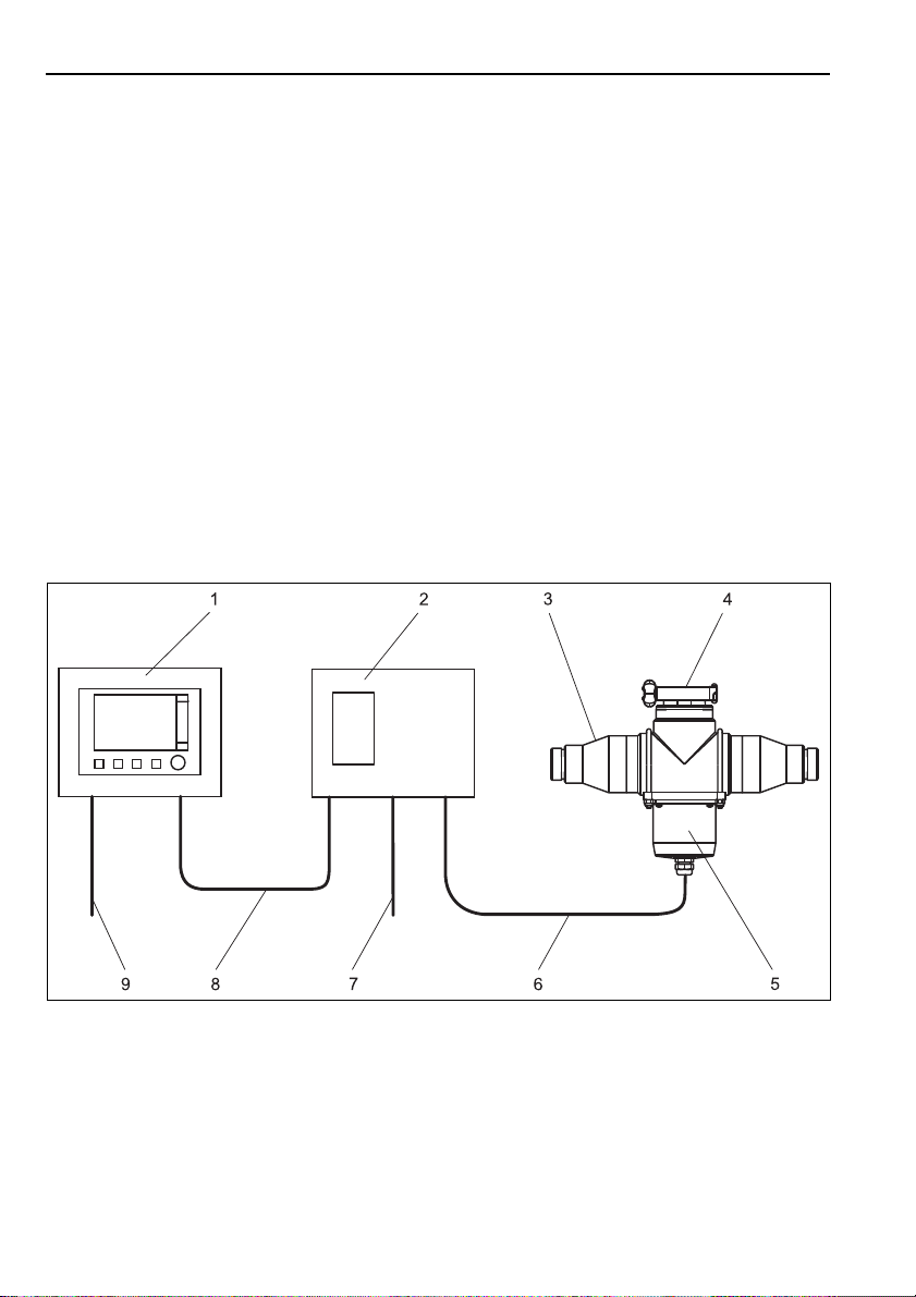
3.1.1 Overview
The complete ultrasonic cleaning system comprises:
• Ultrasonic generator
• Ultrasonic transducer
• Assembly or pipe with turbidity sensor
• Liquiline CM44x transmitter
Fig. 1: Ultrasonic cleaning with Flowfit CUA252 assembly
1
Liquiline CM44x transmitter
2
Ultrasonic generator
3
Flowfit CUA252 flow assembly
4
Clamp connection for turbidity sensor
5
Ultrasonic transducer
6
Power supply cable for ultrasonic transducer
7
Mains voltage cable for ultrasonic generator
8
Control cable
9
Mains voltage cable for transmitter
a0022749
8 Endress+Hauser
Page 9
CYR52 Installation
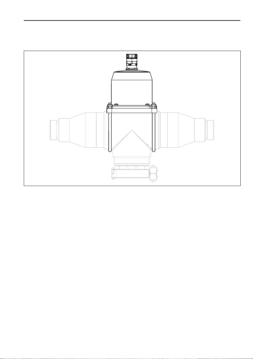
3.1.2 Installation options
With Flowfit CUA252 flow assembly
Fig. 2: Ultrasonic transducer on Flowfit CUA252 assembly
Endress+Hauser 9
a0022751
Page 10
Installation CYR52
With Flowfit CUA262 flow assembly
Fig. 3: Ultrasonic transducer on Flowfit CUA262 assembly
a0022752
10 Endress+Hauser
Page 11

CYR52 Installation
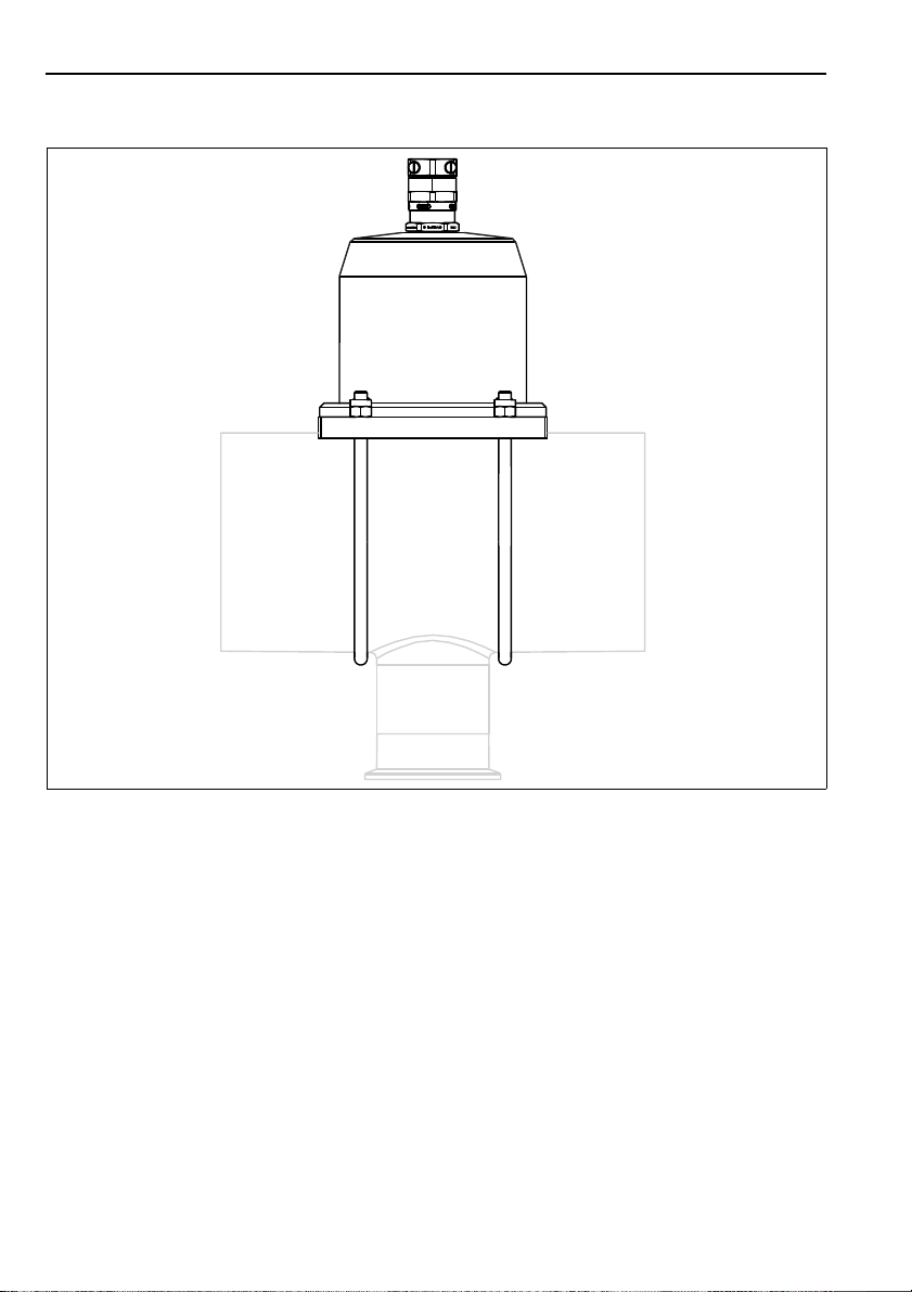
With assembly of CUS31
Fig. 4: Ultrasonic transducer with assembly of CUS31
Endress+Hauser 11
a0022754
Page 12

Installation CYR52
Mounted on a pipe
Fig. 5: Ultrasonic transducer mounted on a pipe
a0022757
12 Endress+Hauser
Page 13

CYR52 Installation
3.2 Installation conditions
3.2.1 Ultrasonic transducer
Fig. 6: Dimensions in mm (inch) for CUA252 and CUA262
a0022750
In the case of the ultrasonic transducer factor in a clearance of approx. 100 mm (4 inch)
above the cable gland for the power supply cable.
Endress+Hauser 13
Page 14

Installation CYR52
Fig. 7: Dimensions in mm (inch) for assembly of CUS31
a0022753
14 Endress+Hauser
Page 15

CYR52 Installation
Fig. 8: Dimensions in mm (inch) for pipe mounting
a0022756
Endress+Hauser 15
Page 16

Installation CYR52
199 (7.38)
162 (6.38)
237 (9.33)
194 (7.64)
128 (5.04)
3.2.2 Ultrasonic generator
Fig. 9: Dimensions in mm (inch)
a0022755
16 Endress+Hauser
Page 17

CYR52 Installation
3.3 Mounting the ultrasonic transducer
The ultrasonic transducer is secured to assemblies with two brackets that are supplied, and to
pipes with two worm drive hose clips that are supplied.
Fig. 10: Ultrasonic contact paste(1)
Mount the ultrasonic transducer as follows:
1. Using the cleaning cloth (scope of delivery) clean the contact surface of the ultrasonic
transducer and the contact surface of the assembly or pipe.
2. Coat the contact surface of the ultrasonic transducer ( å 10, item 1) with a 5 mm
(0.2")stripe ultrasonic contact paste.
3. Mount the ultrasonic transducer face to face with the turbidity sensor.
4. In the case of pipes:
Tighten the two worm drive hose clips with a torque of 2.5 Nm (1.85 lbf ft).
In the case of assemblies:
Tighten the nuts of the brackets with a torque of 2 Nm (1.47 lbf ft).
a0022759
Endress+Hauser 17
Page 18

Installation CYR52
NOTICE
320 (12.6)
270 (10.6)
300 (11.8)
mm (inch)
3.4 Mounting the ultrasonic generator
3.4.1 Mounting plate
Fig. 11: Dimensions in mm (inch)
3.4.2 Weather protection cover (optional)
Effect of climatic conditions (rain, snow, direct sun etc.)
Impaired operation to complete failure of the ultrasonic generator
‣ When installing outside, always use the weather protection cover (accessory)
Fig. 12: Weather protection cover for ultrasonic generator
a0012426
a0019166
18 Endress+Hauser
Page 19

CYR52 Installation
3.4.3 Mounting the ultrasonic generator
Post mounting
You require the post mounting kit (optional) to mount the unit on a pipe, post or railing (square
or round, clamping range 20 to 61 mm (0.79 to 2.40")).
Fig. 13: Post mounting
Spring washers and nuts (post mounting kit)
Weather protection cover (optional)
1
Post mounting plate (post mounting)
2
Spring washers and nuts (post mounting kit)
3
Pipe clamps (post mounting kit)
4
Fig. 14: Post mounting
Endress+Hauser 19
a0012666
5
Pipe or post
6
Mounting plate
7
Threaded rods /post mounting kit)
8
Fig. 15: Attach the device and click it into place
a0012665
a0022760
Page 20

Installation CYR52
2.
1.
Rail mounting
Fig. 16: Rail mounting
Weather protection cover (optional)
1
Post mounting plate (post mounting)
2
Spring washers and nuts (post mounting kit)
3
Pipe clamps (post mounting kit)
4
Spring washers and nuts (post mounting kit)
5
Fig. 17: Rail mounting
a0012669
Pipe or railing /round/square)
6
Mounting plate
7
Threaded rods /post mounting kit)
8
Screws (post mounting kit)
9
Fig. 18: Attach the device and click it into place
a0012668
a0022762
20 Endress+Hauser
Page 21

CYR52 Installation
1.
2.
Wall mounting
Fig. 20: Wall mounting
1Wall
2 4 drill holes
3 Mounting plate
4 Screws Ø 6 mm (no t included in
Fig. 19: Mounting distance in
mm (inch)
1) The size of the drill holes depends on the wall plugs used. The wall plugs and screws must be provided by the customer.
a0012686
the delivery)
1)
a0012684
Fig. 21: Attach the device and click it
into place
a0022767
3.5 Post-installation check
• After installing, check the ultrasonic transducer and ultrasonic generator for damage.
• Check whether the ultrasonic generator is protected against moisture and direct sunlight.
Endress+Hauser 21
Page 22

Electrical connection CYR52
WARNING
!
NOTICE
4 Electrical connection
The device is live!
Incorrect connection may result in injury or death.
‣ The electrical connection may only be established by an electrical technician.
‣ The electrical technician must have read and understood these Operating Instructions and
must follow the instructions they contain.
‣ Prior to beginning any wiring work, make sure voltage is not applied to any of the cables.
‣ It is absolutely imperative to observe the order in which the individual components are
connected.
4.1 Wiring
The device does not have a mains switch
‣ The customer must provide a protected circuit breaker in the vicinity of the device.
‣ The circuit breaker must be a switch or a power-circuit breaker, and you must label it as the
circuit breaker for the device.
Fig. 22: Wiring diagram
AUltrasonic transducer
B Terminal block in ultrasonic generator
C Relay in transmitter
1 Control cable
2Power supply cable
3 Mains connection
22 Endress+Hauser
a0022771
Page 23

CYR52 Electrical connection
Connect the ultrasonic cleaning system in the following order:
1. Connect the control cable (not included in the delivery, H03VV-F 2x0.75 is recommended)
to terminals 1 and 2 at the ultrasonic generator, and to a free relay at the transmitter at
terminals 41 and 42. The assignment of the individual wires is not relevant here. The
maximum cable length is 3 m (9.84 ft). Make sure that the control cable is strain-relieved
in both devices.
2. Connect the cable secured to the ultrasonic transducer to the terminal block of the
ultrasonic generator as follows: connect the yellow-green protective conductor first. Then
connect the gray cable to the negative end (minus) and then the pink cable to the positive
end (plus). Ensure strain relief in the ultrasonic generator.
3. Connect the mains connection cable (not included in the delivery, H05VV-F3 G0.75 is
recommended) to the appropriate terminals of the ultrasonic generator ( å 22,
item 3). Ensure strain relief in the ultrasonic generator.
4.2 Post-connection check
Carry out the following checks after electrical connection:
Device condition and specifications Notes
Are the devices and cables free from damage on the outside? Visual inspection
Does the mains voltage match the specifications on the nameplate?
Electrical connection Notes
Are the mounted cables strain-relieved?
Cable runs without loops and cross-overs?
Are the cables correctly connected according to the wiring diagram?
Are all the screw terminals firmly tightened?
Endress+Hauser 23
Page 24

Commissioning CYR52
WARNING
!
NOTICE
5 Commissioning
5.1 Function check
Incorrect connection, incorrect supply voltage
Safety risks for staff and incorrect operation of the device
‣ Check that all connections have been established correctly in accordance with the wiring
diagram.
‣ Make sure that the supply voltage matches the voltage indicated on the nameplate.
Electrostatic discharge (ESD)
Damage to electronic components
‣ Take personal protective measures to avoid ESD, such as discharging beforehand at PE or
permanent grounding with a wrist strap.
5.2 Configuration
For optimum cleaning performance, the ultrasonic generator is switched on cyclically for a few
seconds. The cleaning cycle is configured in the "Cleaning" menu in the transmitter (see
Operating Instructions of the transmitter).
Fig. 23: Cleaning interval (example)
Enter the following parameters to prevent the ultrasonic transducer from overheating:
Cleaning time: max. 5 seconds
Cleaning interval: min. 5 minutes
Operate the cleaning system only with medium in the pipe system (not dry!).
As soon the transmitter activates the cleaning cycle, the ultrasonic generator starts producing
the sound waves.
24 Endress+Hauser
a0022773
Page 25

CYR52 Diagnostics and troubleshooting
6 Diagnostics and troubleshooting
Error Possible cause Test
Cleaning effect declines Ultrasonic cleaning system is defective Acoustic check (if the ultrasonic
The position of the ultrasonic
transducer has changed.
transducer hums during the cleaning
routine, the cleaning is working)
Check the installation, pay attention to
torque specifications
Endress+Hauser 25
Page 26

Maintenance CYR52
WARNING
!
NOTICE
NOTICE
7 Maintenance
Process pressure and temperature, contamination, electrical voltage
Risk of serious or fatal injury
‣ If the sensor has to be removed during maintenance work, avoid hazards posed by pressure,
temperature and contamination.
‣ De-energize the device before opening it.
‣ Power can be supplied to switching contacts from separate circuits. Also de-energize these
circuits before working on the terminals.
Take all the necessary precautions in time to ensure the operational safety and reliability of the
entire measuring point.
Maintenance of the measuring point comprises:
• Cleaning the transmitter, assembly, ultrasonic transducer and ultrasonic generator
• Checking cables and connections
When performing any work on the device, bear in mind any potential impact this may have on
the process control system or on the process itself.
Electrostatic discharge (ESD)
Damage to electronic components
‣ Take personal protective measures to avoid ESD, such as discharging beforehand at PE or
permanent grounding with a wrist strap.
‣ For your own safety, only use genuine spare parts. With genuine parts, the function,
accuracy and reliability are also ensured after maintenance work.
7.1 Cleaning the transmitter, ultrasonic transducer and ultrasonic generator
Clean the front of the housing with commercially available cleaning agents only.
The front is resistant to the following as per DIN 42 115:
• Ethanol (short periods)
• Diluted acids (max. 2% HCl)
• Diluted bases (max. 3% NaOH)
• Soap-based household cleaners
Prohibited cleaning agents
Danger of damaging the housing surface or housing seal
‣ For cleaning purposes, never use concentrated mineral acids or bases.
‣ Never use organic cleaners such as benzyl alcohol, methanol, methylene chloride, xylene or
concentrated glycerol cleaner.
‣ Never use high-pressure steam for cleaning purposes.
Clean the housing of the ultrasonic transducer with a damp cloth only.
26 Endress+Hauser
Page 27

CYR52 Repair
8Repair
8.1 Spare part kits
Order number Description
71247412 Ultrasonic transducer with 3 m cable
71247419 Ultrasonic transducer with 7 m cable
71247421 Ultrasonic transducer with 15 m cable
71247422 Electronic module 230 V
71247423 Electronic module 115 V
8.2 Return
The product must be returned if repairs or a factory calibration are required, or if the wrong
product has been ordered or delivered. According to legal regulations Endress+Hauser, as an
ISO-certified company, is required to follow certain procedures when handling returned
products that are in contact with the medium.
To ensure swift, safe and professional device returns:
Visit our website to obtain information about the return procedure and basic conditions.
www.services.endress.com/return-material
8.3 Disposal
The device contains electronic components, and must therefore be disposed of in accordance
with regulations on the disposal of electronic waste.
Please observe local regulations.
Endress+Hauser 27
Page 28

Accessories CYR52
320 (12.6)
270 (10.6)
300 (11.8)
mm (inch)
9 Accessories
Description Order number
Mounting paste for CYR52 71242140
Mounting kit for CUA252 71242141
Mounting kit for CUA262 71242142
Mounting kit for flow assembly CUS31 E/S 71242143
Mounting kit, variable 71242145
Post mounting kit for securing the ultrasonic generator to horizontal and
vertical posts and pipes
The CYY101 weather protection cover for field devices is absolutely essential
• Material: stainless steel 1.4301 (AISI 304)
• Order No. CYY101-A
71096920
Fig. 24: Weather protection cover for field devices
a0019166
28 Endress+Hauser
Page 29

CYR52 Technical data
10 Technical data
10.1 Output
10.1.1 Operating frequency of the ultrasonic cleaning system
Approx. 40 kHz
10.2 Power supply
10.2.1 Supply voltage
Depends on the order version:
230 VAC / 50 Hz
115 VAC / 60 Hz
10.2.2 Power consumption
Max. 50 VA
10.3 Environment
10.3.1 Ambient temperature range
Ultrasonic transducer: 0 to 60 °C (32 to 140 °F), non-freezing, non-condensing
Ultrasonic generator: -10 to +60 °C (+14 to 140 °F), non-condensing
10.3.2 Storage temperature
0 to 60 °C (32 to 140 °F)
10.3.3 Electromagnetic compatibility
Interference emission and interference immunity as per EN 61326-1:2006, EN
61326-2-3:2006
10.3.4 Degree of protection
Ultrasonic transducer: IP 68
Ultrasonic generator: IP 66/67
10.3.5 Humidity
10 to 95 %, non-condensing
Endress+Hauser 29
Page 30

Technical data CYR52
10.4 Mechanical construction
10.4.1 Dimensions
See the "Installation" section
10.4.2 Weight
Ultrasonic transducer: 0.72 kg (1.59 lbs), with 3 m cable
Ultrasonic generator: 2.2 kg (4.85 lbs)
10.4.3 Material
Ultrasonic transducer
Cover: PE
Floor: Aluminum
Cable: TPE-U mix; 3xLi9Y 0.75; sheath: Ø 6.6 mm
Minimum bending radius: 66 mm (2.6 inch) when cable
can move freely
33 mm (1.3 inch) when cable cannot move freely
Ultrasonic generator
Housing: PC-FR
Housing seal: EPDM
Cable glands: Polyamide
30 Endress+Hauser
Page 31

CYR52
Index
A
Accessories . . . . . . . . . . . . . . . . . . . . . . . . . . . . 28
C
Check
Electrical connection . . . . . . . . . . . . . . . . . . 23
Function . . . . . . . . . . . . . . . . . . . . . . . . . . . . 24
Post-installation. . . . . . . . . . . . . . . . . . . . . . 21
Commissioning. . . . . . . . . . . . . . . . . . . . . . . . . 24
Configuration . . . . . . . . . . . . . . . . . . . . . . . . . . 24
D
Degree . . . . . . . . . . . . . . . . . . . . . . . . . . . . . . . 29
Designated use . . . . . . . . . . . . . . . . . . . . . . . . . . 4
Dimensions. . . . . . . . . . . . . . . . . . . . . . . . . . . . 30
E
Electrical connection . . . . . . . . . . . . . . . . . . . . 22
Electrical technician . . . . . . . . . . . . . . . . . . . . . 22
Electromagnetic compatibility . . . . . . . . . . . . . . 4
EMC . . . . . . . . . . . . . . . . . . . . . . . . . . . . . . . . . 29
H
Humidity. . . . . . . . . . . . . . . . . . . . . . . . . . . . . . 29
I
Incoming acceptance and product identification 6
Installation . . . . . . . . . . . . . . . . . . . . . . 8, 13, 21
Installation conditions . . . . . . . . . . . . . . . . . . . 13
Installation options . . . . . . . . . . . . . . . . . . . . . . 9
P
Post-connection check . . . . . . . . . . . . . . . . . . 23
Power supply . . . . . . . . . . . . . . . . . . . . . . . . . . 29
Product safety . . . . . . . . . . . . . . . . . . . . . . . . . . . 5
R
Requirements for personnel . . . . . . . . . . . . . . . . 4
Return . . . . . . . . . . . . . . . . . . . . . . . . . . . . . . . 27
S
Safety instructions . . . . . . . . . . . . . . . . . . . . . . . 4
Scope of delivery . . . . . . . . . . . . . . . . . . . . . . . . . 6
Spare part kits . . . . . . . . . . . . . . . . . . . . . . . . . 27
Storage . . . . . . . . . . . . . . . . . . . . . . . . . . . . . . 29
T
Technical data . . . . . . . . . . . . . . . . . . . . . . . . . 29
U
Use. . . . . . . . . . . . . . . . . . . . . . . . . . . . . . . . . . . . 4
W
Weather protection cover . . . . . . . . . . . . . . . . 18
Weight . . . . . . . . . . . . . . . . . . . . . . . . . . . . . . 30
Wiring . . . . . . . . . . . . . . . . . . . . . . . . . . . . . . . 22
Workplace safety . . . . . . . . . . . . . . . . . . . . . . . . 4
M
Maintenance
Entire measuring point . . . . . . . . . . . . . . . . 26
Material . . . . . . . . . . . . . . . . . . . . . . . . . . . . . . 30
Mechanical construction . . . . . . . . . . . . . . . . . 30
Mounting plate. . . . . . . . . . . . . . . . . . . . . . . . . 18
N
Nameplate . . . . . . . . . . . . . . . . . . . . . . . . . . . . . 7
O
Operational safety . . . . . . . . . . . . . . . . . . . . . . . 4
Output. . . . . . . . . . . . . . . . . . . . . . . . . . . . . . . . 29
Overview. . . . . . . . . . . . . . . . . . . . . . . . . . . . . . . 8
Endress+Hauser
Page 32

www.addresses.endress.com
71261315
 Loading...