

Page 1
Products ServicesSolutions
Operating Instructions
Liquiline To Go Ex CYM291
Page 2

Page 3
Basics
Warranty
Defects occurring within 3 years from delivery date shall be remedied free of charge
at our plant (carriage and insurance paid by sender).
Subject to change.
Return of Products Under Warranty
Please contact our Service Team before returning a defective device.
Ship the cleaned device to the address you have been given.
If the device has been in contact with process uids, it must be decontaminated/
disinfected before shipment. In that case, please attach a corresponding certicate,
for the health and safety of our service personnel.
Disposal
Please observe the applicable local or national regulations concerning
the disposal of “waste electrical and electronic equipment”.
3
Registered Trademarks
The following names are registered trademarks. For practical reasons they are shown
without trademark symbol in this manual.
• Memosens®
• Liquiline®
• Sensocheck®
• Sensoface®
Page 4

4
Package Contents ............................................................................... 6
Documentation ................................................................................... 7
Overview ............................................................................................. 8
Value-Added Features ..............................................................................................9
Protective Cover ....................................................................................................... 10
Hook ............................................................................................................................10
Display ........................................................................................................................ 11
Keypad ........................................................................................................................12
Start-Up ............................................................................................. 13
Inserting the Batteries ........................................................................................... 13
Batteries for Application in Hazardous Locations........................................ 14
Connecting a Sensor .............................................................................................. 15
Switching On the Meter ........................................................................................ 16
Icons ............................................................................................................................ 16
Conguring .......................................................................................17
Conguration (pH) .................................................................................................. 17
Conguration (Cond) ............................................................................................. 18
Conguration (Oxy) ................................................................................................ 19
pH Calibration ................................................................................... 20
Conductivity Calibration .................................................................. 24
Oxygen Calibration ..........................................................................27
Measuring .........................................................................................31
Toggling the Measured Value Display .............................................................31
Adjusting the Temperature .................................................................................. 31
Data Logger ......................................................................................32
Operating Modes of the Data Logger (Logger Type) .................................33
Data Logger Menu .................................................................................................. 35
Conguring the Data Logger .............................................................................. 36
Starting the Data Logger using CONT ............................................................. 37
Starting the Data Logger using START ............................................................ 37
Displaying the Logger Data ................................................................................. 38
Stopping the Data Logger ...................................................................................39
Clearing the Data Logger ..................................................................................... 39
Table of Contents
Page 5

Table of Contents
Clock ..................................................................................................40
Error and Status Messages ...............................................................41
”Sensoface” Messages ............................................................................................ 42
Error Messages ......................................................................................................... 43
pH Product Line ................................................................................ 44
pH Sensors ................................................................................................................. 44
Endress+Hauser Buer Solutions (pH) ...........................................................45
Ready-to-use quality pH buer solutions.......................................................45
Accessories for pH ................................................................................................... 45
Conductivity Product Line ............................................................... 46
Conductivity Sensors ............................................................................................. 46
CLY11 Conductivity Calibration Solutions......................................................47
Accessories for Conductivity ............................................................................... 47
Oxygen Product Line ........................................................................ 48
Oxygen Sensors ....................................................................................................... 48
Accessories for Oxygen ......................................................................................... 48
Specications .................................................................................... 49
Index .................................................................................................. 54
5
Page 6
6
Check the shipment for transport damage and completeness.
The package of the Liquiline To Go Ex CYM291 includes:
Meter incl. 4 AA batteries
and premounted quiver
Carrying strap
Data carrier with detailed user manuals
USB cable, 1.5 m
Safety instructions
Quickstart instructions in various languages
Certicates
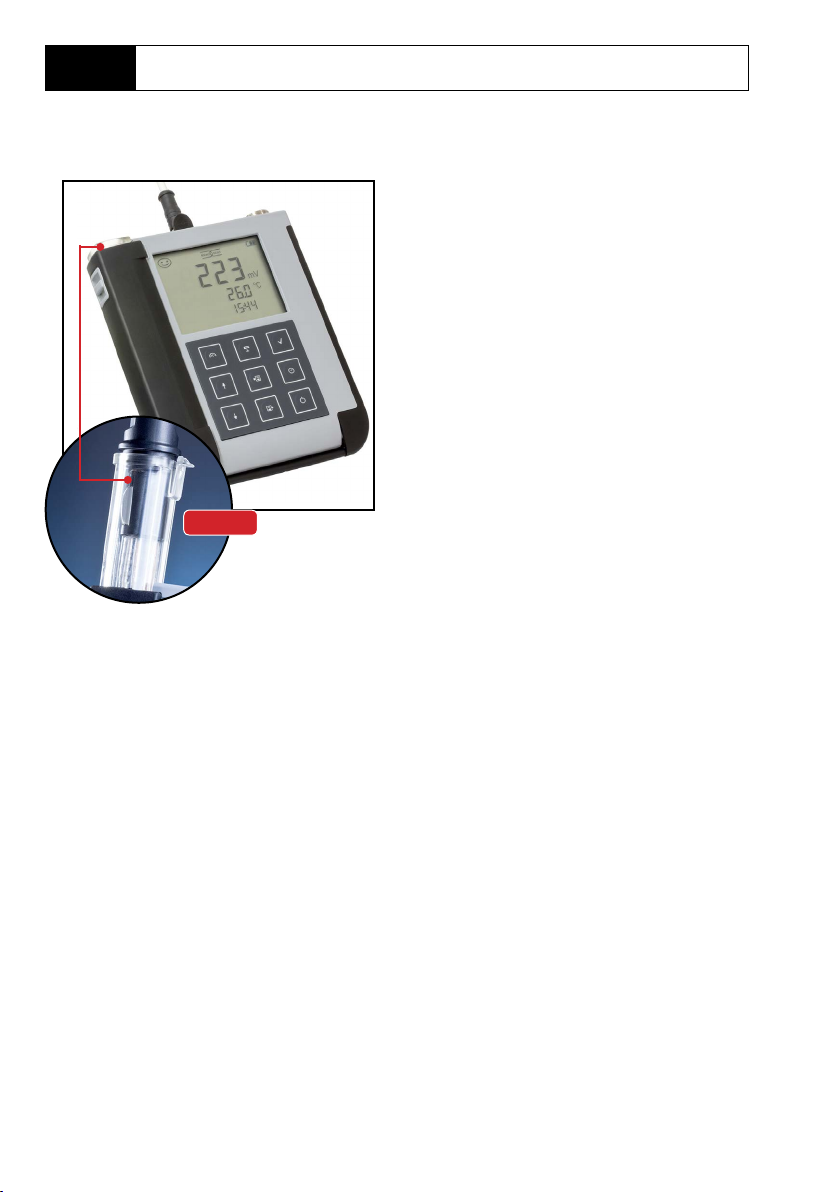
Package Contents
Liquiline To Go Ex CYM291
Page 7
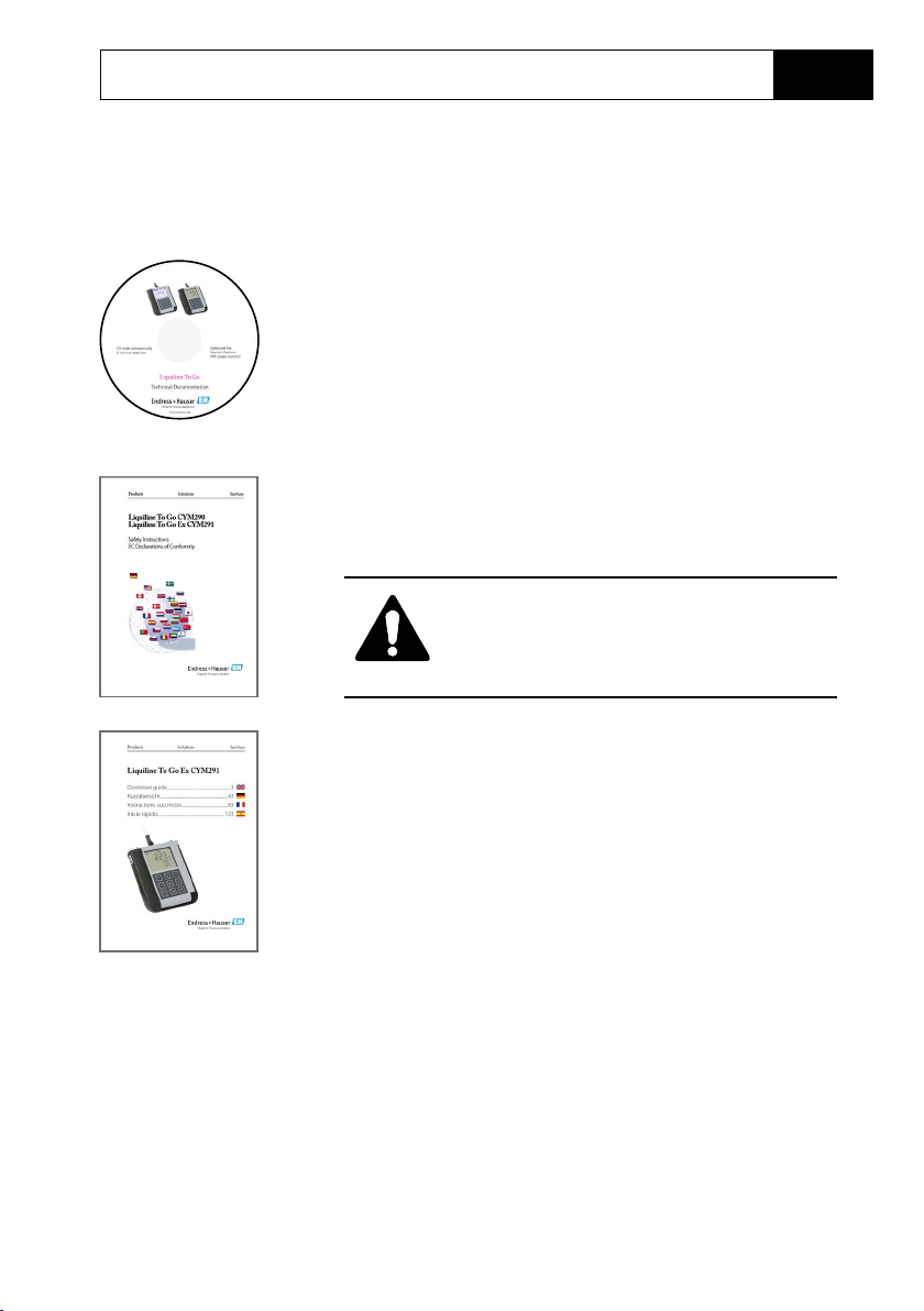
Documentation
Specic Test Report
CD-ROM
Complete documentation:
• User manuals in dierent languages
• Safety instructions
• Certicates
• Quickstart guides
Safety Instructions
In ocial EU languages and others.
• EU Declarations of Conformity
7
CAUTION!
These safety instructions are part of the
product documentation and must be
observed.
Quickstart Guides
Installation and rst steps:
• Operation
• Menu structure
• Calibration
• Error messages and recommended actions
Various languages on CD-ROM:
• German
• English
• French
• Italian
• Spanish
• Portuguese (Brazil)
Certicates
Page 8
8
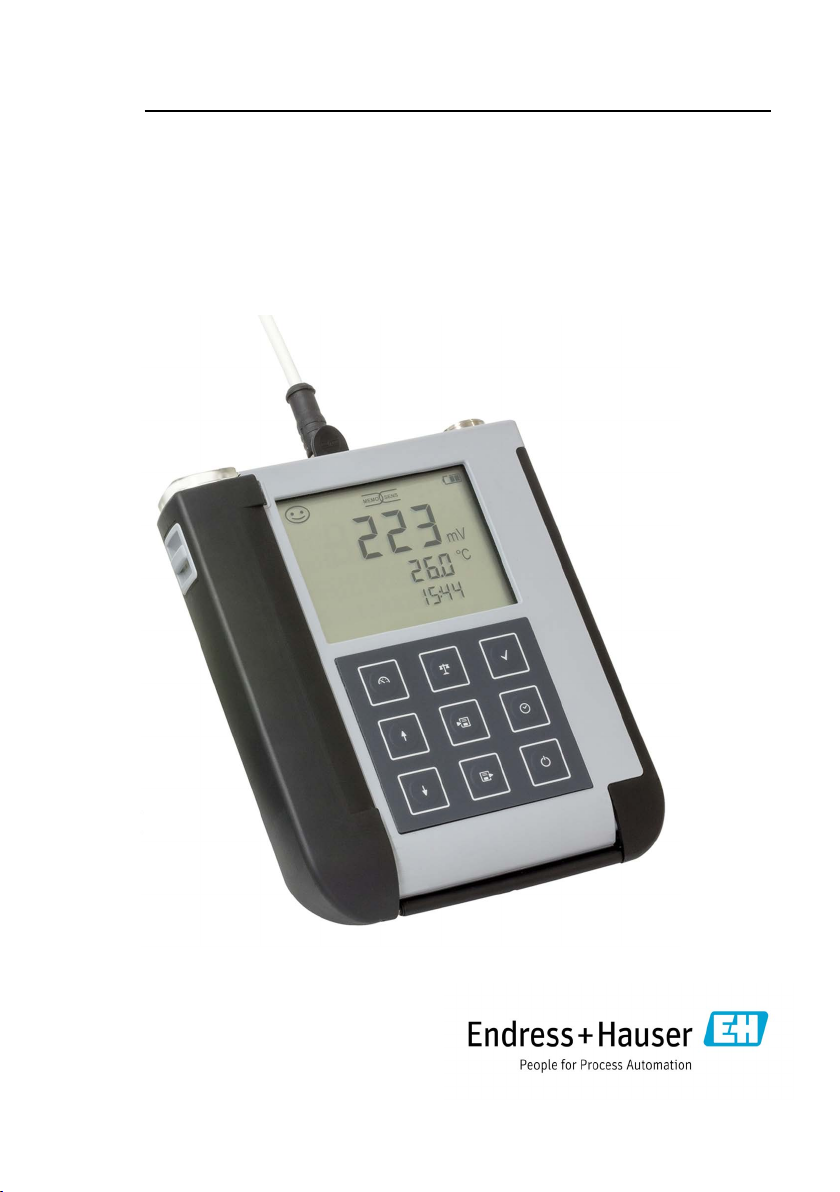
Overview
The Liquiline To Go Ex CYM291 is
a portable multiparameter meter for
measuring pH, ORP, conductivity
or oxygen. With a plain text line on a
high-contrast LCD, operation is largely
intuitive.
Quiver
The meter stands out by the following features:
• Application in hazardous locations up to Zone 0
• Use of digital Memosens sensors
• A detachable quiver protects the sensor and prevents it from drying out.
Furthermore, it can be used for calibration.
• The rugged housing is made of a high-performance polymer. It provides high
impact resistance and dimensional stability even when exposed to extreme
moisture.
• Scratch-proof clear glass display, perfectly readable even after years
• Very long operating time with one set of batteries (4 x AA) for reliable operation
even at high or very low operating temperatures
• Data logger with 5000 values
• Micro USB port
• Sensoface icons provide single-glance information on the sensor condition
(page9)
• Real-time clock and indication of battery charging level
Page 9
Overview
Value-Added Features
Memosens
The Liquiline To Go Ex CYM291 can communicate
with Memosens sensors. These digital sensors are
automatically identied and the meter switches to
the appropriate measurement method.
When a Memosens sensor is connected to the
meter, it is indicated by the logo shown on the
right. Furthermore, Memosens allows the storage
of calibration data, which will be available and
can still be used when the sensor is connected to
another Memosens-capable device.
Sensoface
Sensoface provides quick information on the
sensor condition. The three “smiley” faces as shown
on the right represent the sensor condition during
measurement and after a calibration. When the
condition deteriorates, an “INFO …” message gives
a hint to the cause.
9
Programmed buers
“Programmed buers” is a very convenient method
for pH calibration with automatic buer recognition. You only have to select the buer set with the
buers used. The buers can then be used in any
order.
Page 10
10
Overview
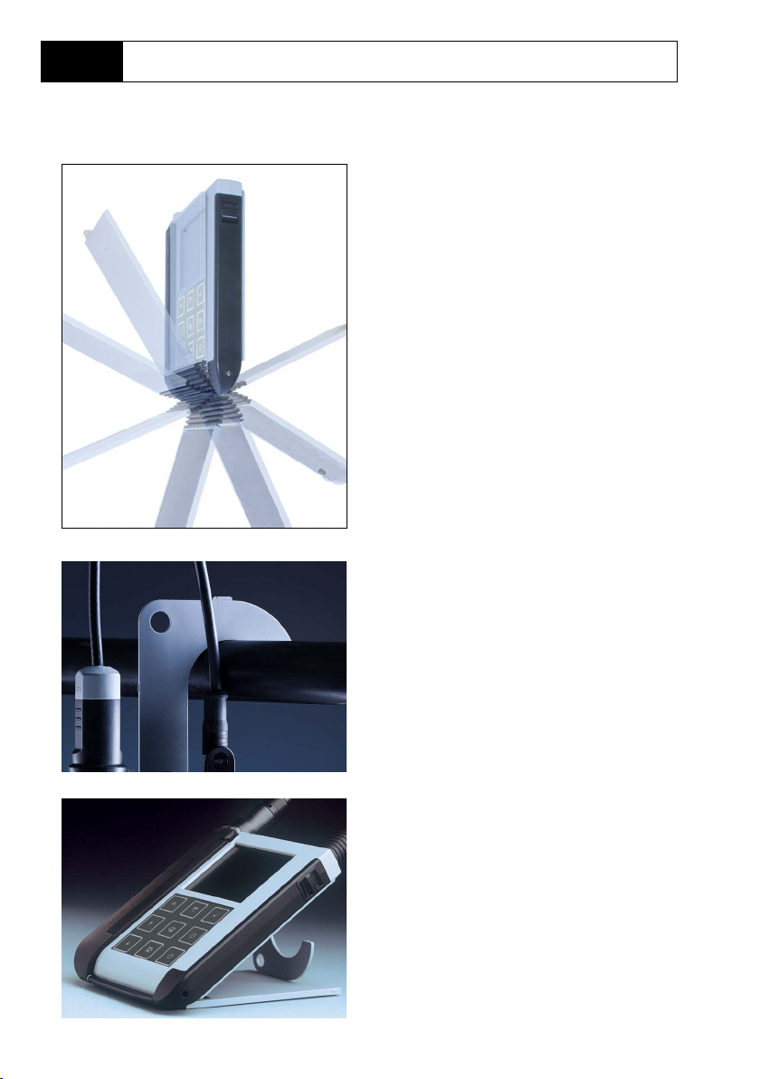
Protective Cover
The front of the meter is protected
by a cover, which can be completely
ipped over and secured to the back for
operation.
Hook
A fold-out hook on the back allows
suspending the meter. This leaves your
hands free for the actual measurement.
The rating plate is located beneath the
hook.
Protective Cover and Hook
Combined
Cover and hook can be joined together
to form a benchtop stand allowing comfortable and fatigue-free working at a lab
bench or desk.
Page 11
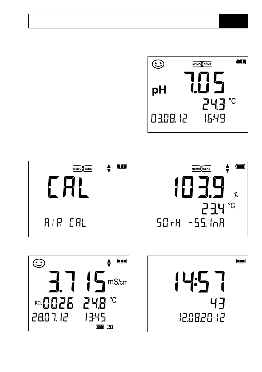
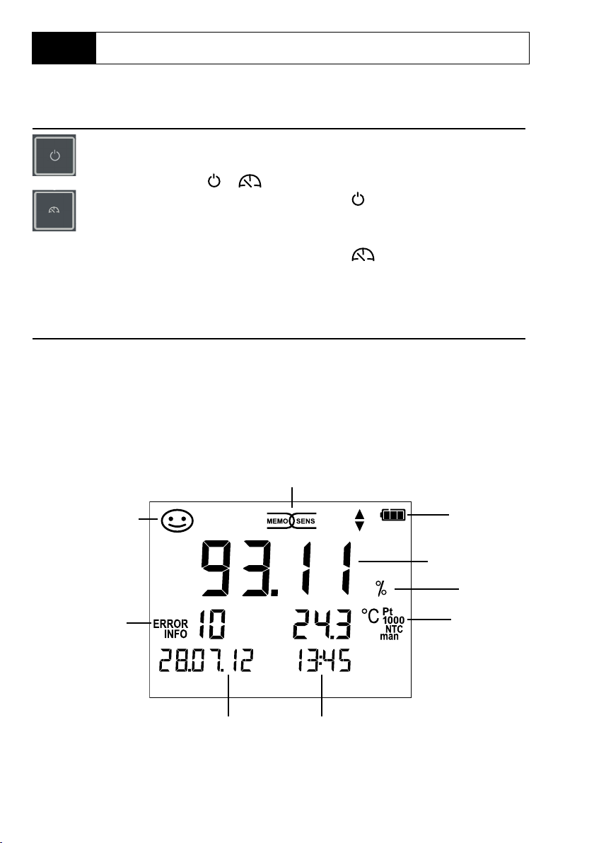
Overview
Display
The meter has a three-line display for
representing alphanumeric information such as measurement and calibration data, temperatures and date/time.
Additional information is provided by
means of icons (Sensoface, battery
icon, etc.).
Some typical displays are shown here.
11
pH measurement
(display of measured value, temperature, date and time)
Oxygen calibration – step 1
(calibration in air)
Logger data for conductivity
(display of measured value, memory
location, temperature, date and time)
Oxygen calibration – step 2
(adjusting the relative humidity)
Clock
(display of hours and minutes, seconds
and date)
Page 12
12
Overview
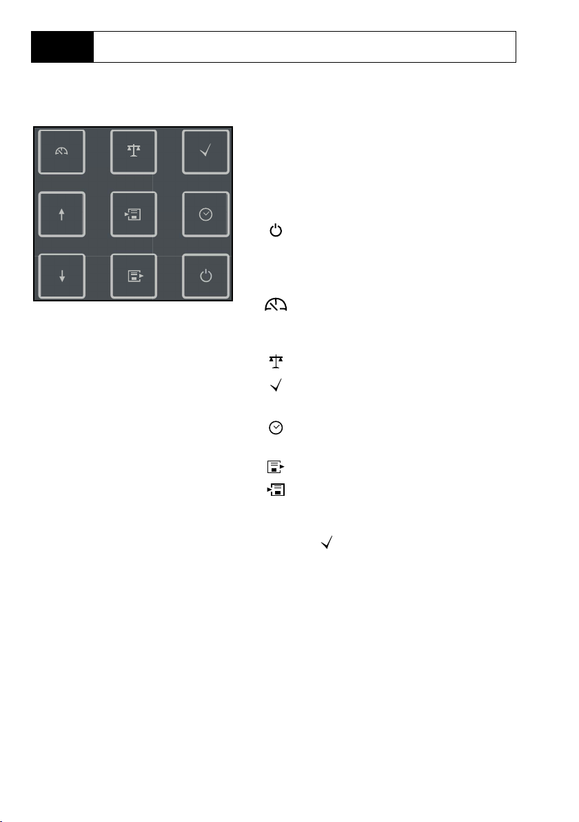
Keypad
The keys of the membrane keypad
have a noticeable pressure point.
They have the following functions:
Switches the meter on and
displays the device and
calibration data
(see Start-up)
Switches the meter on /
Activates measuring mode /
Stops the data logger
Starts calibration
Activates conguration /
Conrms entries
Displays time and date, allows
setting the clock using set
View stored values
Holds and saves a measured
value, allows setting and
starting the logger by pressing (page 32)
When this icon is displayed,
▲
▼
you can use the arrow keys
for navigation.
Page 13
Start-Up
Check the shipment for transport damage and completeness (see Package
Contents).
NOTICE!
Do not operate the device when one of the following conditions applies:
• the device shows visible damage
• the device fails to perform the intended function
• prolonged storage at temperatures above 70 °C
• severe transport stresses
In this case, a professional routine test must be performed.
This test should be carried out at our factory.
Precautions for application in hazardous locations
WARNING!
• Only open the battery compartment of the Liquiline To Go Ex CYM291
outside the hazardous location.
• Never try to open the device. If a repair should be required, return the
device to our factory.
• Never use the USB port within the hazardous location.
13
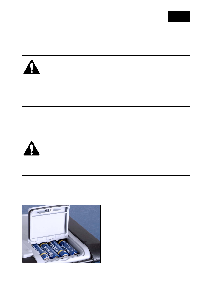
Inserting the Batteries
With four AA batteries, the Liquiline ToGo
Ex CYM291 has an operating time of
approx. 500h.
Open the battery compartment on the
rear of the device. Be sure to observe the
correct polarity when inserting the batter‑
ies (see markings in the battery chamber).
Close the battery compartment cover and
screw it handtight.
Page 14
14
A battery icon in the display indicates the battery power level:
Icon fully lled Batteries at full capacity
Icon partially lled Battery capacity is sucient
Icon empty Battery capacity not sucient;
calibration is possible, no logging
Icon blinks Only a few operating hours remaining,
measurement is still possible
NOTICE! It is absolutely necessary to replace
the batteries.
WARNING!
When operating the Liquiline To Go Ex CYM291 in a hazardous loca‑
tion, only the battery types listed below may be used. The batteries
must be from the same manufacturer and of identical type and
capacity. Never use new and used batteries together (“Certicates”,
Control Drawing 209.009‑150).
Start-Up
Batteries for Application in Hazardous Locations
Batteries (4x each) Temp. class Ambient temperature range
Duracell MN1500 T4 –10 °C ≤ Ta ≤ +40 °C
Energizer E91 T3 –10 °C ≤ Ta ≤ +50 °C
Power One 4106 T3 –10 °C ≤ Ta ≤ +50 °C
Panasonic Pro Power LR6 T3 –10 °C ≤ Ta ≤ +50 °C
Page 15
Start-Up
15
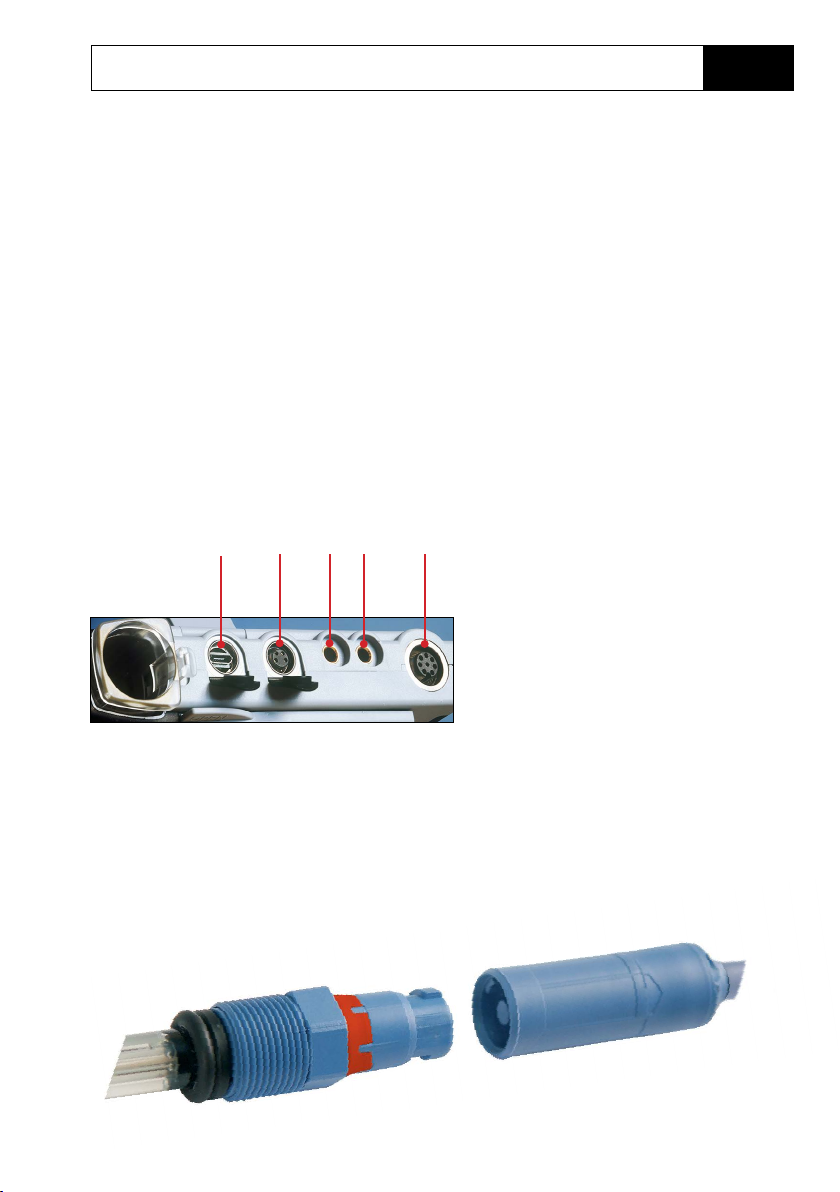
Connecting a Sensor
The Liquiline To Go Ex CYM291 provides several connections so that many types of
sensors can be used for measurement (see illustration below). Note that only one
sensor may be connected to the meter at a time. The meter recognizes the connected Memosens sensor and displays the Memosens logo.
Separate temperature probe
After power-on, a separate temperature probe is automatically recognized. When
you want to replace the temperature probe, you must switch o the meter and then
switch it on again.
a b c d
Memosens sensors have a cable coupling, which allows convenient replacement
of sensors while the cable remains connected to the meter. The connecting cable is
connected to socket b (M8, 4 pins) or e (M12, 8 pins).
e
Connections
a - Micro USB port
b - M8, 4 pins, for Memosens lab cable
c - Temperature probe – GND
d - Temperature probe
e - M12, 8 pins, for Memosens sensors
Page 16
16
Switching On the Meter
When you have connected the sensor, you can switch the meter on
by pressing the or key.
When the meter is switched on with the key, rst a self test is
performed and then the calibration data and settings are displayed
before the meter switches to measuring mode.
When the meter is switched on with the key, it immediately
switches to measuring mode.
Depending on the connected sensor and the specic measuring task, several steps for conguration and calibration must be
performed as described on the following pages.
Icons
Important information about the state of the device:
Start-Up
Sensor condition
Error message
Memosens sensor
Date
Battery
charging level
Measured value
Measured
variable
Temperature
detection
(sensor,
separate or
manual)
Time
Page 17
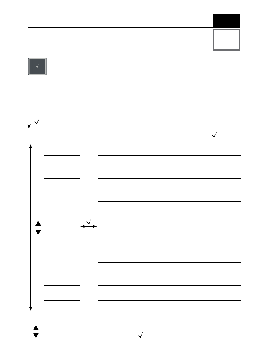
Conguring
Conguration (pH)
Conguration is required to match the connected sensor and the
desired measurement performance. Furthermore, you can select the
suitable calibration method. The following table gives you an overview. Factory settings are shown in bold print.
Measurement
17
pH
“Setup” display
Display 1 pH x.xx | pH x.xxx | mV
Display 2 OFF | date + time | date | time
CAL Timer OFF | 1 ... 99 days
CAL
CAL POINTS 1 | 2 | 3 | 1-2-3 (for PROG.BUFFERS, Manual, FREE CAL)
BUFFER SET
(PROG.BUFFERS, FREE
CAL)
Auto OFF OFF| 0.1h | 1h | 6h | 12h
Temp Unit °C | °F
Time Format 24h | 12h
Date Format dd.mm.yy | mm.dd.yy
Default
Select using arrow keys, conrm by pressing .
PROG.BUFFERS|Manual|DATA INPUT|(ISFET-Zero)|
FREE CAL
-01- Endress+Hauser 2.00|4.01|6.98|9.95|11.87
-02- Mettler-Toledo 2.00|4.01|7.00|9.21
-03- Knick CaliMat 2.00|4.00|7.00|9.00|12.00
-04- Ciba (94) 2.06|4.00|7.00|10.00
-05- NIST technical 1.68|4.00|7.00|10.01|12.46
-06- NIST standard 1.679|4.006|6.865|9.180
-07- HACH 4.01|7.00|10.01|12.00
-08- WTW techn. buers 2.00|4.01|7.00|10.00
-09- Hamilton 2.00|4.01|7.00|10.01|12.00
-10- Reagecon 2.00|4.00|7.00|9.00|12.00
-11- DIN 19267 1.09|4.65|6.79|9.23|12.75
NO | YES (reset to factory settings)
Note: All data logger entries will be deleted.
This icon prompts you to select a menu item using the arrow keys –
the selection is conrmed by pressing .
Page 18
18
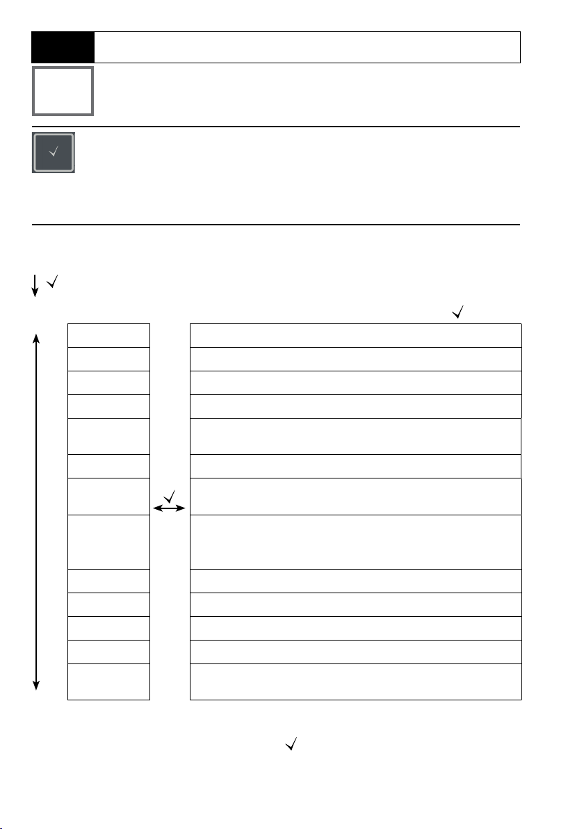
Cond
Measurement
Conguration (Cond)
Conguration is required to match the connected sensor and the
desired measurement performance. Furthermore, you can select the
suitable calibration method. The following table gives you an overview. Factory settings are shown in bold print.
“Setup” display
Display Cond | SAL g/kg | TDS mg/l
MOHM cm OFF | On
Cond Unit mS/cm | S/m
TDS Factor 0.0 … 1.0 (if display = TDS)
TC * OFF | LINEAR | NLF | NACL | HCL | NH3 | NAOH
TC LINEAR 0.0 … 20.0 %/K | 2.0 %/K (if TC = LINEAR)
REF. Temp. 0 … 100 °C | 25 °C ( 32 … 212 °F | 77 °F)
s
t
CAL CELL CONST. | COND | <25°C> 74.0µS/cm |
Auto OFF OFF | 0.1h | 1h | 6h | 12h
Temp. Unit °C | °F
Time Format 24h | 12h
Date Format dd.mm.yy | mm.dd.yy
Default NO | YES (reset to factory settings)
Select using arrow keys, conrm by pressing .
(if display = Cond)
(if TC = LINEAR)
<25°C> 149.6µS/cm | <25°C> 1.406mS/cm |
<25°C> 12.64mS/cm | <25°C> 107.00mS/cm |FREE CAL
Note: All data logger entries will be deleted.
s
This icon prompts you to select a menu item using the arrow keys –
t
the selection is conrmed by pressing
* Temperature compensation
.
Page 19
Conguring
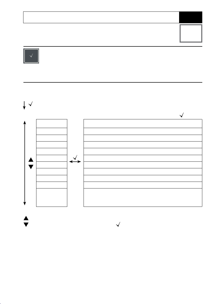
Conguration (Oxy)
Conguration is required to match the connected sensor and the
desired measurement performance. Furthermore, you can select the
suitable calibration method. The following table gives you an overview. Factory settings are shown in bold print.
Measurement
19
Oxy
“Setup” display
Display 1 Saturation in % air | Concentration in mg/l
Display 2 OFF | date + time | date | time
Altitude 0 … 4000 m
Salt Correct 0.0 … 45.0 g/kg
CAL AIR CAL | ZERO CAL | DATA INPUT | FREE CAL
CAL Timer OFF | 1 … 99 days
Auto OFF OFF | 0.1h | 1h | 6h | 12h
Temp Unit °C | °F
Time Format 24h | 12h
Date Format dd.mm.yy | mm.dd.yy
Default NO | YES (reset to factory settings)
This icon prompts you to select a menu item using the arrow keys –
the selection is conrmed by pressing .
Select using arrow keys, conrm by pressing .
Note: All data logger entries will be deleted.
Page 20
20
pH
Measurement
pH Calibration
“Programmed Buers” Calibration
(Calibration with automatic buer recognition)
The calibration method is selected in the conguration menu.
Calibration is required to adjust the sensor to the meter. It is indis‑
pensable for achieving comparable and reproducible measurement
results.
CAL
PROG. BUFFERS
CAL 1/2/3
PRESS CAL
pH, mV value,
Calibration method, the number of calibration points and
the buer set have been selected in the conguration
menu.
Dip sensor in 1st/2nd/3rd buer solution.
It does not matter which buer solution is taken rst.
temperature
Depending on the number of calibration points, the
procedure described above for CAL 1/2/3 is repeated.
mV value blinks until calibration is completed, then successive display of:
CAL DATA
1/2/3 CAL POINTS
ZERO POINT
SLOPE
Then the meter switches to measuring mode.
Please note: To abort calibration, you can press at any time.
This will be conrmed by the display message “CAL ABORTED”.
Exception: When you have selected “CAL POINTS 1‑2‑3” and the rst calibration step
has been completed, the calibration process cannot be stopped any more.
Page 21

pH Calibration
DATA INPUT Calibration
(Calibration by entering known sensor values)
The calibration method is selected in the conguration menu.
Measurement
CAL
DATA INPUT
21
pH
ZERO POINT
SLOPE
The calibration data will be displayed successively:
Date and time
ZERO POINT
SLOPE
Then the meter switches to measuring mode.
Please note: To abort calibration, you can press at any time.
st to select the value for the zero point.
Use
st to select the value for the slope.
Use
Page 22

22
pH
Measurement
pH Calibration
MANUAL Calibration
(Manual calibration)
The calibration method is selected in the conguration menu.
CAL
MANUAL
CAL 1/2/3
PRESS CAL
pH display blinks
PRESS CAL
mV display blinks
mV value blinks until calibration is completed, then successive display of:
CAL DATA
1/2/3 CAL POINTS
ZERO POINT
SLOPE
Then the meter switches to measuring mode.
The number of calibration points has been
selected in the conguration menu.
Take the temperature‑corrected pH value from
the buer description and enter it using
Depending on the number of calibration points,
the procedure described above for CAL 1/2/3 is
repeated.
st.
Please note: To abort calibration, you can press
This will be conrmed by the display message “CAL ABORTED”.
Exception: When you have selected “CAL POINTS 1‑2‑3” and the rst calibration step
has been completed, the calibration process cannot be stopped any more.
at any time.
Page 23

Measurement
23
pH
FREE CAL Calibration
(Free selection of calibration method)
FREE CAL calibration is selected in the conguration menu.
CAL
PROG. BUFFERS blinks
Perform the selected calibration (see PROG. BUFFERS, DATA INPUT or MANUAL
calibration).
st to select the required calibration
Use
method (PROG. BUFFERS, DATA INPUT or
MANUAL).
Page 24

24
Cond
Measurement
Conductivity Calibration
CELL CONST. Calibration
(Calibration by entry of cell constant)
The calibration method is selected in the conguration menu.
CAL
CELL CONST.
Value blinks
Calibration will be performed. Automatic return to measuring mode.
The conductivity will be shown in the display
and can be compared with a reference solution
(temperature‑corrected).
st to select the value for the cell constant.
Use
COND Calibration
(Calibration by entry of conductivity)
The calibration method is selected in the conguration menu.
Measurement
CAL
COND
Dip sensor in solution.
Value blinks
Calibration will be performed. Automatic return to measuring mode.
Use st to adjust the temperature‑corrected
conductivity value. NOTICE: Here, the meter
does not perform a temperature compensation!
Page 25

Conductivity Calibration
Calibration with Calibration Solution
(Automatic calibration with preselected calibration solution)
The calibration method is selected in the conguration menu.
NOTICE!
• Make sure that the values of the calibration solutions used
correspond exactly to those specied in this manual.
If not, the resulting cell constant will be incorrect.
• When calibrating in a liquid, make sure that the sensor, the
separate temperature probe (if present) and the calibration
solution have the same temperature. Only this ensures that the
cell constant is determined correctly.
Measurement
25
Cond
CAL
<25°C> 107.00mS/cm
PRESS CAL
Measured value
Temperature
Cal solution conductivity
Hourglass blinks
Calibration will be performed. Automatic return to measuring mode.
Dip sensor in calibration solution.
The meter automatically compensates for the
temperature deviation!
Page 26

26
Cond
Measurement
Conductivity Calibration
FREE CAL Calibration
(Free selection of calibration method)
FREE CAL calibration is selected in the conguration menu.
CAL
CELL CONST. blinks
Perform the selected calibration (see CELL CONST., COND or calibration solution).
st to select the desired calibration
Use
method (CELL CONST., COND, <25°C>
74.0µS/cm, <25°C> 149.6µS/cm, <25°C>
1.406mS/cm, <25°C> 12.64mS/cm, <25°C>
107.00mS/cm).
Page 27

Oxygen Calibration
AIR CAL Calibration
(Calibrating the slope in air)
The calibration method is selected in the conguration menu.
Measurement
27
Oxy
CAL
AIR CAL
Measured value
Temperature
xxx rH blinks
xxx nA blinks
Hourglass blinks
CAL DATA
Date
SLOPE xxx nA
Automatic return to measuring mode.
Place sensor in air and wait until the measured
values have stabilized.
Use
humidity.
Calibration will be performed.
Slope calibration data is displayed.
st to adjust the correct value for relative
Please note: To abort calibration, you can press
at any time.
Page 28

28
Oxy
Measurement
CAL
ZERO CAL
Oxygen Calibration
ZERO CAL Calibration
(Zero calibration with oxygen-free medium)
The calibration method is selected in the conguration menu.
xxx
nA
PRESS CAL blinks
CAL DATA Calibration will be performed.
Date
ZERO P. xxx nA
Date
SLOPE xxx nA
Automatic return to measuring mode.
Please note: To abort calibration, you can press
Place sensor in oxygen‑free medium (e.g.,
nitrogen 5.0) and wait until the measured values
have stabilized.
Zero calibration data is displayed.
Slope calibration data is displayed.
at any time.
Page 29

Oxygen Calibration
DATA INPUT Calibration
(Calibration by entering known sensor values)
The calibration method is selected in the conguration menu.
Measurement
CAL
DATA INPUT
29
Oxy
xx blinks
nA
ZERO POINT
xxx blinks
nA
SLOPE
Calibration will be performed. Automatic return to measuring mode.
Please note: To abort calibration, you can press
st to adjust the known value for the
Use
sensor zero point.
st to adjust the known value for the
Use
sensor slope.
at any time.
Page 30

30
Oxy
Measurement
Oxygen Calibration
FREE CAL Calibration
(Free selection of calibration method)
FREE CAL calibration is selected in the conguration menu.
CAL
AIR CAL blinks
Perform the selected calibration (see AIR CAL, ZERO CAL or DATA INPUT
calibration).
st to select the desired calibration
Use
method (AIR CAL, ZERO CAL, DATA INPUT).
Page 31

Measuring
31
pH Oxy Cond
Once you have completed all preparations, you can start with
the actual measurement.
1) Connect the desired sensor to the meter. Some sensors
require a special preparation. Please proceed according to
the operating instructions for the sensor.
2) Switch the device on using the
3) Depending on the measurement method and the sensor
used, immerse the sensing part of the sensor in the medium
to be measured.
4) Watch the display and wait for the reading to stabilize.
5) By pressing the
value (see data logger, page 32).
key, you can hold and save a measured
or key.
Toggling the Measured Value Display
During measurement, you can toggle the measured value
display by pressing :
• pH: between pH and mV
• Cond: between compensated and uncompensated
measured value (when temperature compensation, SAL or
TDS are activated)
• Oxy: not applicable
Keys for
measurement
Adjusting the Temperature
When you connect a sensor without temperature detector,
you can manually adjust the temperature for measurement or
calibration:
1) Press to access measuring mode.
The adjusted temperature will be displayed.
2) Set the desired temperature value using the or arrow.
Holding the key depressed changes the temperature value
at high speed.
Page 32

32
Data Logger
pH Oxy Cond
Data Logger
The meter provides a data logger. Prior to use, it must be congured and then
activated. You can choose from the following logger types:
• DIFF (signal-controlled logging of measured variable and temperature)
• INT (time-controlled logging at a xed interval)
• DIFF+INT (combined time- and signal-controlled logging)
• SHOT (manual logging by pressing the key)
The data logger records up to 5000 entries and saves them in a circular buer.
Already existing entries will be overwritten.
The following data are recorded: primary value, temperature, time stamp and device
status.
Display: Icons related to the data logger
Memory
address
(0026)
Measured
value is being
saved:
:
Measured
values are
displayed
Next value
Primary
process
variable
Temperature
DateData logger activated
Time
Logger type
Page 33

Data Logger
pH Oxy Cond
Operating Modes of the Data Logger (Logger Type)
Manual logging when logger is activated (SHOT)
In this mode, a measured value is recorded when the key is pressed.
Measurement
Logger activated
The measured value is saved to the address of the last recorded value + 1
Manual logging when logger is deactivated
Measurement
Logger deactivated
33
Measured value is maintained
Proposed address blinks
(address of the last recorded
value + 1)
Measured value is saved to the desired address (e.g., for overwriting an incorrect
measurement).
Interval (INT)
In this mode, the measured values are cyclically recorded.
Measured parameter
= entry
If desired: Select start address
using st.
Example: Logger type “INT”
Time
Page 34

34
Data Logger
pH Oxy Cond
Dierence (DIFF)
When the delta range (process variable and/or temperature) related to the last entry
is exceeded, a new entry is created and the delta range is displaced upwards or
downwards by the delta value. The rst entry is automatically created when the data
logger is started.
Example: First entry = 2, Delta = 1
Measured parameter
4
Delta
3
Delta
2
Delta
1
Delta
= entry
Dierence + Interval combined (DIFF+INT)
When the delta range related to the last DIFF entry is exceeded, a new entry is created (example: entry A) and the delta range is displaced upwards or downwards by the
delta value. As long as the measured value remains within the delta range, logging
is performed at the preset interval. The rst DIFF entry is automatically created when
the data logger is started.
Measured parameter
4
3
Delta
2
Delta
1
Start logger
Delta
A
Example: Logger type “Interval + Dierence”
Interval
= entry
Time
Time
Page 35

Data Logger
Data Logger Menu
Logger display
CONT Select start address and start the data logger
START Deletes all entries and starts the data logger at start
s
t
DEL Deletes all entries
SET Select logger type and congure:
Overview of data logger menu (default in bold print)
Select using arrow keys, conrm by pressing
address 0001
DIFF, INT, DIFF+INT, SHOT (see table below)
35
pH Oxy Cond
.
Logger
type
DIFF Delta % air OFF | 0.1 … 100 % air | 1.0 % air
OFF | 0.01 … 20 mg/l | 1.00 mg/l
Delta pH OFF | pH 0.01…14.00 | pH 1.00
OFF | 1… 1000 mV | 1 mV
Delta Cond OFF | 1 … 1000 mS/cm
OFF | 0.1 … 100 S/m | 1 S/m
Delta SAL OFF | 0.1 … 45.0 g/kg
Delta TDS OFF | 1 … 1999 mg/l
Delta °C / °F OFF | 0.1 … 50.0 °C | 1.0 °C
OFF | 0.1 …90 °F | 1.0 °F
INT Interval h:mm:ss
0:00:01 … 9:59:59 | 12:02:00 AM
DIFF+INT DIFF See logger type DIFF
INT See logger type INT
SHOT Currently selected process variable is recorded
Page 36

36
pH Oxy Cond
Conguring the Data Logger
Prerequisite: The data logger is stopped (press ).
Measurement
Measured value is maintained
Logger: CONT blinks
t
Logger: START blinks
t
Logger: DEL blinks
t
Logger: SET blinks
Data Logger
Logger: Current logger type
blinks
Select the appropriate parameters using st and conrm each selection by pressing . When conguration is nished, CONT blinks. You can start the data logger
by selecting START or CONT (see page 37).
Select desired logger type using st:
DIFF, INT, DIFF+INT or SHOT.
Page 37
Data Logger
37
pH Oxy Cond
Starting the Data Logger using CONT
Prerequisite: Data logger is congured. Every time the meter has been switched o,
the data logger must be restarted (exception: SHOT).
Measurement
Measured value is maintained
Logger: CONT blinks
Address of the last recorded value
+1 blinks
(proposed start address)
The measured value is saved to the selected start address (exception: SHOT).
“… FREE MEMORY” is displayed.
“LOGGER” and “active logger type” icons are displayed.
If desired: Select start address using st.
Starting the Data Logger using START
Prerequisite: Data logger is congured. All existing entries are deleted.
The start address for saving the values is 0001. Every time the meter has been
switched o, the data logger must be restarted (exception: SHOT).
Measurement
Measured value is maintained
Logger: CONT blinks
t
Logger: START blinks
All entries will be deleted. “5000 FREE MEMORY” is displayed.
“LOGGER” and “active logger type” icons are displayed.
Page 38

38
pH Oxy Cond
Displaying the Logger Data
Pressing the key displays all stored values.
Measurement
Data Logger
The “RCL” icon and the last recorded value is displayed.
or
Return to measurement
Use st to select the desired address. Empty
memory locations will also be displayed.
Example:
Measured value stored at location 0026
Example:
Empty memory location 0004
Page 39

Data Logger
39
pH Oxy Cond
Stopping the Data Logger
You can stop the data logger at any time by pressing the key.
Measurement, logger activated
Data logger is stopped. “LOGGER” and “active logger type” icons are no longer
displayed. It is still possible to hold a measured value by pressing and send it to
any desired address.
Clearing the Data Logger
Selecting “DEL” deletes all data records.
Measurement
Measured value is maintained
Logger: CONT blinks
t
Logger: START blinks
t
Logger: DEL blinks
PRESS SET
All stored data are deleted.
“0000 DELETED” is displayed.
Page 40

40
pH Oxy Cond
Press the key to access the clock mode. Date and time will be
displayed in the format as set in the conguration menu.
To set the clock, proceed as follows:
Display of
time+date
Clock
Hour display blinks
SET HOUR
Minute display blinks
SET MINUTE
Seconds display blinks
and shows 00
Year display blinks
SET YEAR
Month display blinks
SET MONTH
Day display blinks
SET DAY
Set value.
Set value.
Clock is started, the seconds count up.
Set value.
Set value.
Set value.
Display of
corrected time+date
Page 41

Error and Status Messages
41
pH Oxy Cond
Error messages are indicated as “ERROR …” on the display. Information on the sensor
condition is indicated by the “Sensoface” icon (friendly, neutral, sad) possibly accompanied by an info message (“INFO …”).
Example of an error message:
ERROR 1 (value out of range)
Sensoface (the “smiley” icon) provides
information on the sensor condition (maintenance request). Measurement can still be
performed. After a calibration, the corresponding Sensoface icon (friendly, neutral,
sad) is shown together with the calibration
data. Otherwise, Sensoface is only visible in
measuring mode.
The most important error messages and
“Sensoface” info messages are shown on
the inside of the protective cover.
A complete list of messages and their
meanings is provided in the following
tables.
Example of a “Sensoface” message:
INFO 1 (cal timer expired)
Page 42

42
pH Oxy Cond
”Sensoface” Messages
The “Sensoface” icon provides information on the sensor condition:
Sensoface Meaning
Sensor is okay
Calibrate the sensor soon
Calibrate or replace the sensor
The “neutral” and “sad” Sensoface icons are accompanied by an “INFO …” message to
give a hint to the cause of deterioration.
Sensoface Message Cause
INFO 1 Calibration timer
INFO 3 Sensocheck
INFO 5 Zero/Slope
INFO 6 Response time
INFO 7 Operating point (asymmetry potential)
INFO 8 Leakage current
INFO 9 ORP oset
INFO 10 Polarization
Page 43

Error and Status MessagesError and Status Messages
pH Oxy Cond
Error Messages
The following error messages can be shown in the display.
Message Cause Remedy
43
blinks
ERROR 1 Value out of range
ERROR 2 ORP value out of range
ERROR 3 Temperature value out of
ERROR 4 Zero point too high/low Thoroughly rinse the sensor and recal-
ERROR 5 Slope too high/low
ERROR 6 Cell constant too high/low Enter nominal cell constant or calibrate
ERROR 8 Calibration error:
ERROR 9 Calibration error:
ERROR 10 Calibration media
ERROR 11 Measured value unstable
ERROR 14 Time and date invalid Set time and date
ERROR 18 Conguration invalid Restart, reset to factory settings,
ERROR 19 Factory settings error Device defective, send it in.
ERROR 21 Sensor error
ERROR 22 Sensor conict Connect only one sensor.
Battery empty Replace batteries
Check whether the measurement
conditions correspond to the adjusted
range
Identical buers
Buer unknown
interchanged
Stability criterion not met
(Memosens)
measuring range.
ibrate. If this does not help, replace the
sensor.
the sensor using a known solution.
Use a buer solution with a dierent
nominal value before starting the next
calibration step.
Make sure that you use the same
buer set as congured.
Repeat calibration.
Leave the sensor in the liquid until the
temperature is stable. If this does not
help, replace the sensor.
congure and calibrate. If this does not
help, send in the device for repair.
Connect operational Memosens
sensor.
Page 44

44
pH
pH Sensors
pH Product Line
Product Name
(Link to Product Congurator)
Orbisint CPS11D Digital pH sensor
Orbisint CPS12D Digital ORP sensor
Memosens CPS16D Combined digital pH/ORP sensor
Memosens CPS31D Digital pH sensor
Ceraliquid CPS41D Digital pH sensor
Ceraliquid CPS42D Digital ORP sensor
Ceragel CPS71D Digital ORP sensor
Ceragel CPS72D Digital ORP sensor
Memosens CPS76D Combined digital pH/ORP sensor
Orbipore CPS91D Digital pH sensor
Orbipore CPS92D Digital ORP sensor
Memosens CPS96D Combined digital pH/ORP sensor
Ceramax CPS341D Digital non-glass pH sensor
Tophit CPS441D Digital non-glass pH sensor
Tophit CPS471D Digital non-glass pH sensor
Tophit CPS491D Digital non-glass pH sensor
Orbipac CPF81D Digital pH sensor
Orbipac CPF82D Digital ORP sensor
The Product Congurator can be accessed at: www.endress.com/<product name>
Sensor Type
Memosens sensors have a cable coupling, which allows convenient replacement of
sensors while the cable remains connected to the meter.
Page 45

45
pH
Endress+Hauser Buer Solutions (pH)
Ready-to-use quality pH buer solutions
Quality buers from Endress+Hauser - CPY20
Solutions which are traced by a DAkkS-accredited Endress+Hauser buer laboratory
(DkkS = German Accreditation Body) to a primary reference material of the PTB and
to standard reference material of the National Institute of Standards and Technology (NIST) in accordance with DIN 19266 are used as secondary reference buer
solutions.
CPY20 Buer Sets Quantity
pH 2.00 5000 ml / 100 ml / 250 ml
pH 4.01 5000 ml / 100 ml / 250 ml / 18 ml
pH 6.98 5000 ml / 100 ml / 250 ml / 18 ml
pH 9.95 5000 ml / 100 ml / 250 ml
pH 11.87 5000 ml / 100 ml / 250 ml
Accessories for pH
Item
1.5 m sensor cable ATEX CYK20 BAB1C2
CPY7 electrolyte vessel, reservoir for KCI electrolyte, 150ml
The Product Congurator can be accessed at:
www.endress.com
Page 46

46
Cond
Conductivity Sensors
Conductivity Product Line
Product Name
(Link to Product Congurator)
Condumax CLS15D Conductivity sensor
Condumax CLS16D Conductivity sensor
Condumax CLS21D Conductivity sensor
Memosens sensors have a cable coupling, which allows convenient replacement of
sensors while the cable remains connected to the meter.
Sensor Type
Page 47

47
Cond
CLY11 Conductivity Calibration Solutions
CLY11-A, 74 μS/cm (reference temp. 25°C (77 °F)), 500ml (16.9 fl.oz)
CLY11-B, 149.6 μS/cm (reference temp. 25°C (77 °F)), 500ml (16.9 fl.oz)
CLY11-C, 1.406 mS/cm (reference temp. 25°C (77 °F)), 500ml (16.9 fl.oz)
CLY11-D, 12.64 mS/cm (reference temp. 25°C (77 °F)), 500ml (16.9 fl.oz)
CLY11-E, 107.00 mS/cm (reference temp. 25°C (77 °F)), 500ml (16.9 fl.oz)
Accessories for Conductivity
Item (Link to Product Congurator)
1.5 m sensor cable ATEX CYK20 BAB1C2
Conducal CLY421 calibration set
• Conductivity calibration set (case) for ultrapure water applications
• Complete, factory-calibrated measuring set with certicate, traceable to SRM
of NIST and DKD, for comparative measurement in ultrapure water up to
max.20μS/cm
• Product Congurator on the product page: www.endress.com/cly421
The Product Congurator can be accessed at:
www.endress.com
Page 48

48
Oxygen Product Line
Oxy
Oxygen Sensors
Product Name
(Link to Product Congurator)
Oxymax COS22D digital oxygen sensor
Accessories for Oxygen
Item
COS22Z maintenance kit
1.5 m sensor cable ATEX CYK20 BAB1C2
The Product Congurator can be accessed at:
www.endress.com
Page 49

Specications
49
pH Oxy Cond
Connections 1x M8 socket, 4 pins, for Memosens lab cable
Display LCD STN 7-segment display with 3 lines and icons
Sensoface Status indication (friendly, neutral, sad)
Status indicators For battery power level, logger
Notices Hourglass
Keypad
Data logger With up to 5000 memory locations
Recording Manual, interval- or event-controlled
Communication USB 2.0
Profile HID, driverless installation
Usage Data exchange
Diagnostics
Sensor data
(Memosens only)
Calibration data Calibration date; zero and slope, or cell constant, resp.
Device self-test Automatic memory test (FLASH, EEPROM, RAM)
Device data Device type, software version, hardware version
Data retention Parameters, calibration data > 10 years
EMC EN 61326-1 (General Requirements)
Emitted interference Class B (residential area)
Immunity to interference Industry
Explosion protection CYM291
1 x M12 socket, 8 pins, for Memosens sensors
2 x 4-mm socket for separate temperature detector
1 x micro USB-B
Be sure to observe the safety instructions when using the USB port.
], [ ], [ ], [ ], [▲], [▼], [ ], [ ], [ ]
[
Manufacturer, sensor type, serial number, operating time
EN 61326-2-3
(Particular Requirements for Transmitters)
Global IECEx Ex ia IIC T4/T3 Ga
Europe ATEX II 1 G Ex ia IIC T4/T3 Ga
Page 50

50
pH Oxy Cond
RoHS conformity According to directive 2011/65/EU
Power supply 4 x AA batteries
Operating time Approx. 500 h (alkaline)
Nominal operating conditions
Ambient temperature -10 °C ≤ Ta ≤ +40 °C (+14 ... +104 °F) T4 Duracell MN1500
Transport/Storage temp. -25 … +70 °C (-13 ... +158 °F)
Relative humidity 0 … 95 %, short-term condensing allowed
Housing
Material PA12 GF30 (silver gray RAL 7001) + TPE (black)
Protection IP 66/67 with pressure compensation
Dimensions Approx. (132 x 156 x 30) mm
Weight Approx. 500 g
For battery types, see Control Drawing No. 209.009-150
-10 °C ≤ Ta ≤ +50 °C (+14 ... +122 °F) T3 Energizer E91,
Power One 4106
and Panasonic Pro Power LR6
Page 51

Specications
51
pH
Memosens pH input
(also ISFET)
Display ranges
Memosens input
ORP
Display ranges
Sensor standardization * ORP calibration (zero adjustment)
Permissible calibration range ΔmV (offset) -700 … +700 mV
Sensor standardization * pH calibration
Operating modes * PROG.BUFFERS Calibration with automatic buffer recognition
“Programmed buffers”
buffer sets *
Permissible calibration range Zero point 6 ... 8 pH
Calibration timer * Interval 1 … 99 days, can be switched off
Sensoface Provides information on the sensor condition
Evaluation of zero/slope, response, calibration interval
1)
1)
M8 socket, 4 pins, for Memosens lab cable or
M12 socket, 8 pins, for Memosens sensors
pH -2.00 … +16.00
mV -1999 … +1999 mV
Temperature -50 … +250 °C (-58 ... +482 °F)
M8 socket, 4 pins, for Memosens lab cable or
M12 socket, 8 pins, for Memosens sensors
mV -1999 … +1999 mV
Temperature -50 … +250 °C (-58 ... +482 °F)
MANUAL Manual calibration with entry of individual
DATA INPUT Data entry of zero and slope
-01- Endress+Hauser 2.00/4.01/6.98/9.95/11.87
-02- Mettler-Toledo 2.00/4.01/7.00/9.21
-03- Knick CaliMat 2.00/4.00/7.00/9.00/12.00
-04- Ciba (94) 2.06/4.00/7.00/10.00
-05- NIST technical 1.68/4.00/7.00/10.01/12.46
-06- NIST standard 1.679/4.006/6.865/9.180
-07- HACH 4.01/7.00/10.01/12.00
-08- WTW techn. buffers 2.00/4.01/7.00/10.00
-09- Hamilton 2.00/4.01/7.00/10.01/12.00
-10- Reagecon 2.00/4.00/7.00/9.00/12.00
-11- DIN 19267 1.09/4.65/6.79/9.23/12.75
With ISFET:
Operating point
(asymmetry)
Slope Approx. 74 … 104 %
(possibly restricting notes from Sensoface)
buffer values
-750 … +750 mV
* User-defined
1) Ranges depending on Memosens sensor
Page 52

52
Cond
Conductivity input M8 socket, 4 pins, for Memosens lab cable
Measuring ranges CLS15D k = 0.01 : 0-20 µS/cm
CLS16D k = 0.1 : 0.04 µS/cm - 500 µS/cm
CLS21D k = 1 : 10.0 µS/cm - 20.0 mS/cm
Permissible cell constant 0.005 … 200.0 cm
Measuring cycle Approx. 1 s
Temperature compensation Linear 0 … 20 %/K, reference temperature adjustable
Display resolution
(autoranging)
Sensor standardization Cell constant Input of cell constant with simultaneous dis-
Measurement error
1,2,3)
nLF: 0 … 120 °C
NaCl
HCl (ultrapure water with traces)
NH3 (ultrapure water with traces)
NaOH (ultrapure water with traces)
Conductivity 0.001 μS/cm (c < 0.05 cm
Resistivity 00.00 … 99.99 MΩ cm
Salinity 0.0 … 45.0 g/kg (0 … 30 °C)
TDS 0 … 1999 mg/l (10 … 40 °C)
Input of solution Input of conductivity of the calibration
Auto Automatic determination of the cell constant
< 0.5 % meas.val. + 0.4 µS * c
k = 0.1 : 0-200 µS/cm
-1
(adjustable)
0.01 μS/cm (c = 0.05 … 0.2 cm–1)
0.1 μS/cm (c > 0.2 cm–1)
play of conductivity value and temperature
solution with simultaneous display of cell
constant and temperature
with calibration solution
4)
–1
)
1) according to EN 60746-1, at nominal operating conditions
2) ± 1 count
3) plus sensor error
4) c = cell constant
Page 53

Specications
53
Oxy
Memosens input, oxygen M8 socket, 4 pins, for Memosens lab cable or
Display ranges
Temperature meas. range 1)-20 … +150 °C
Sensor standardization Automatic calibration in air (100 % RH)
1) Ranges depending on Memosens sensor
1)
M12 socket, 8 pins, for Memosens sensors
Saturation 0.000 ... 200.0 %
Concentration 000 μg/l … 20.00 mg/l
Zero calibration
Page 54

54
0000 DELETED (“data deleted” display) 39
A
AA batteries 13
Accessories for conductivity 47
Accessories for oxygen 48
Accessories for pH 45
AIR CAL (Oxy calibration) 27
Altitude (Oxy conguration) 19
Arrow keys 12
Automatic calibration (Cond) 25
Automatic pH calibration (Programmed buers) 20
B
Batteries 14
Batteries for application in hazardous locations 14
Battery capacity 14
Battery charge indicator 14
Battery compartment 13
Battery icon 14
Battery replacement 13
Benchtop stand 10
Buer sets CPY20 45
Buer set selection 17
Buer solutions 45
C
Calibration, conductivity 24
Calibration set Conducal CLY421 47
CD-ROM 7
Cell constant (Cond calibration) 24
Certicates 7
Charge level of batteries 14
Clearing the datalogger 39
Clock 40
Cond conguration 18
Conductivity calibration, CELL CONST 24
Conductivity calibration, FREE CAL 26
Conductivity calibration solutions CLY11 47
Index
Page 55

Conductivity calibration, with cal solution 25
Conductivity sensors 46
Conductivity sensors, product line 46
Conguration (Cond) 18
Conguration (Oxy) 19
Conguration (pH) 17
Conguring the data logger 36
Connecting a sensor 15
Connecting cable for Memosens 15
Connections 15
Continuous recording of measured values 33
Control functions 12
CONT, starting the data logger 37
Cyclic recording of measured values 33
D
DATA INPUT (Oxy calibration) 29
DATA INPUT (pH calibration) 21
Data logger 32
Data logger conguration 36
Data logger icons 32
Data logger menu 35
Data memory 32
Data of the meter 49
Date 40
Default (conguration) 17
Deleting data logger entries 39
Delta range (data logger) 34
Device conguration (Cond) 18
Device conguration (Oxy) 19
Device conguration (pH) 17
Device messages 41
Dierence (data ogger mode) 34
Dierence+Interval (data logger mode) 34
Digital sensors, conductivity 46
Digital sensors, oxygen 48
Digital sensors, pH 44
55
Page 56

56
Display 11
Display icons 16
Displaying the data logger 32
Displaying the time and date 40
Disposal 3
Documentation 7
Duracell MN1500 battery 14
E
Electrolyte vessel, CPY7 45
Energizer E91 battery 14
ERROR (error codes) 43
Error messages 41
Error messages, overview 43
EU Declarations of Conformity 7
F
FREE CAL, free selection of calibration method (Cond) 26
FREE CAL, free selection of calibration method (Oxy) 30
FREE CAL, free selection of calibration method (pH) 23
H
Hazardous location, batteries 14
Holding the measured value 33
Hook 10
Hours, display 40
I
Icons 16
Icons for data logger 32
INFO messages 42
Inserting the batteries 13
Interrupting the data logger 39
Interval (data logger mode) 33
Introduction 8
Index Index
Page 57

Index
K
Keypad 12
L
Logger 32
Logger display 35
Logger type (data logger modes) 33
M
Manual calibration (Cond) 24
Manual calibration (pH) 22
Measured-value recording 33
Measuring 31
Memory for measured values 32
Memosens cable, description 9
Memosens connecting cable 15
Memosens sensors, conductivity 46
Memosens sensors, pH 44
Menu of data logger 35
Menu structure of Cond conguration 18
Menu structure of data logger 35
Menu structure of Oxy conguration 19
Menu structure of pH conguration 17
Messages 41
Messages, “Sensoface” 42
Micro USB port 15
Minutes, display 40
N
Nitrogen 5.0 28
O
on/o key 12
Operating modes of the data logger 33
ORP sensors 44
Overview of Cond conguration 18
Overview of error messages 43
Overview of Oxy conguration 19
Overview of pH conguration 17
57
Page 58

58
Oxy conguration 19
Oxygen calibration, AIR CAL 27
Oxygen calibration, DATA INPUT 29
Oxygen calibration, FREE CAL 30
Oxygen calibration, ZERO CAL 28
Oxygen-free medium 28
Oxygen sensors 48
P
Package contents 6
Panasonic Pro Power LR6 battery 14
Parameter setting, data logger 36
Parameter settings (Cond conguration) 18
Parameter settings (Oxy conguration) 19
Parameter settings (pH conguration) 17
pH buer solutions 45
pH calibration, DATA INPUT 21
pH calibration, FREE CAL 23
pH calibration, MANUAL 22
pH calibration, PROG. BUFFERS 20
pH conguration 17
pH sensors 44
Ports 15
Power-on 16
Power One 4106 battery 14
Product range 44
Programmed buers, description 9
Programmed buers (pH calibration) 20
Protective cover 10
Q
Quickstart guides 7
Index Index
Page 59

Index
R
Rating plate 10
Real-time clock 40
Recorded data, display 38
Redox sensors 44
Registered trademarks 3
Replacing the batteries 13
Reservoir for KCI electrolyte 45
Reset to factory settings (Default) 17
Return of products under warranty 3
S
Safety instructions 7
Saving the currently measured value 33
Seconds, display 40
Sensoface, description 9
Sensoface messages 42
Sensor connection 15
Sensors for oxygen, product line 48
Sensors for pH, product line 44
Sensor without temperature detector 31
Settings for conductivity measurement 18
Settings for oxygen measurement 19
Settings for pH measurement 17
Setting the data logger 36
Setup (Cond conguration) 18
Setup (Oxy conguration) 19
Setup (pH conguration) 17
SHOT (data logger mode) 33
Smiley 42
Specications 49
Specic test report 7
Start address (data logger) 33
Starting the data logger using CONT 37
Starting the data logger using START 37
START, starting the data logger 37
Start-up 13
59
Page 60

60
Status messages 41
Stopping the data logger 39
Structure of data logger 35
Suspending the meter 10
Switching on the meter 12, 16
Switching the measured value display 31
Symbols in display 16
T
T3, temperature class 14
T4, temperature class 14
Table of Cond conguration 18
Table of error messages 43
Table of Oxy conguration 19
Table of pH conguration 17
Technical data 49
Temperature class 14
Temperature, manual adjustment 31
Temperature probe 15
Toggling the measured value display 31
Trademarks 3
Triangle icons 12
V
Value-added features 9
Viewing recorded data 38
Viewing the logger data 38
W
Warranty 3
Z
ZERO CAL (Oxy calibration) 28
Index
Page 61

Page 62

Page 63

Page 64

088989
www.addresses.endress.com
Endress+Hauser Conducta GmbH+Co. KG
Dieselstraße 24
70839 Gerlingen - Germany
Phone: +49 7156 209 790
Fax: +49 7156 28 158
TA-209.4MU-EHE01 20150413 Software version: 1.x
71265352
 Loading...