

Page 1
0
BA00118C/07/A2/04.18
71395993
Products Solutions Services
Operating Instructions
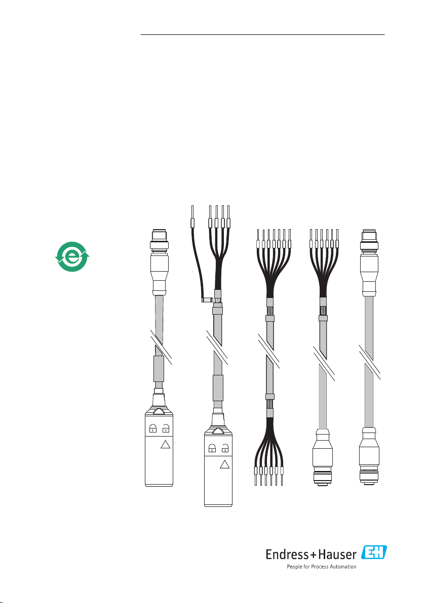
CYK10/11
Memosens-Datenkabel
Memosens data cables
Page 2
CYK10/11
2 Endress+Hauser
Page 3

CYK10/11
CYK10/11
Memosens-Datenkabel
Memosens data cables
Betriebsanleitung ................................................................... 5
Operating Instructions ............................................................. 21
Endress+Hauser 3
Page 4

Page 5

CYK10/11 Inhaltsverzeichnis
Inhaltsverzeichnis
1 Hinweise zum Dokument ...... 6
1.1 Warnhinweise ....................... 6
1.2 Symbole ............................ 6
2 Grundlegende
Sicherheitshinweise ............ 7
2.1 Anforderungen an das Personal ........ 7
2.2 Bestimmungsgemäße Verwendung ..... 7
2.3 Arbeitssicherheit ..................... 7
2.4 Betriebssicherheit .................... 7
2.5 Produktsicherheit .................... 8
3 Warenannahme und
Produktidentifizierung ....... 10
3.1 Warenannahme .................... 10
3.2 Produktidentifizierung ............... 10
4 Anschlussschema (Ex-
Bereich) ........................ 12
5 Montage ....................... 13
5.1 CYK11-Verbindungsdose an eine Wand
montieren ......................... 13
5.2 CYK11-Verbindungsdose an ein Rohr
montieren ......................... 14
6 Elektrischer Anschluss ........ 14
6.1 CYK10 anschließen .................. 15
6.2 CYK11 anschließen .................. 15
6.3 CYK11-Verbindungsdose anschließen .. 18
7 Zubehör ........................ 20
Endress+Hauser 5
Page 6
Hinweise zum Dokument CYK10/11
1 Hinweise zum Dokument
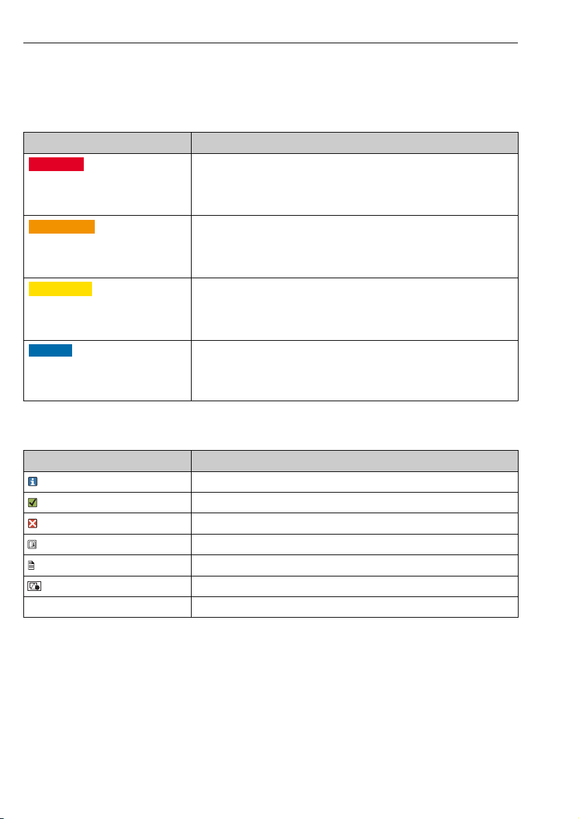
1.1 Warnhinweise
Struktur des Hinweises Bedeutung
GEFAHR
L
Ursache (/Folgen)
Ggf. Folgen der Missachtung
Maßnahme zur Abwehr
‣
WARNUNG
L
Ursache (/Folgen)
Ggf. Folgen der Missachtung
Maßnahme zur Abwehr
‣
VORSICHT
L
Ursache (/Folgen)
Ggf. Folgen der Missachtung
Maßnahme zur Abwehr
‣
HINWEIS
Ursache/Situation
Ggf. Folgen der Missachtung
Maßnahme/Hinweis
‣
1.2 Symbole
Dieser Hinweis macht Sie auf eine gefährliche Situation aufmerksam.
Wenn Sie die gefährliche Situation nicht vermeiden, wird dies zum Tod oder
zu schweren Verletzungen führen.
Dieser Hinweis macht Sie auf eine gefährliche Situation aufmerksam.
Wenn Sie die gefährliche Situation nicht vermeiden, kann dies zum Tod oder
zu schweren Verletzungen führen.
Dieser Hinweis macht Sie auf eine gefährliche Situation aufmerksam.
Wenn Sie die gefährliche Situation nicht vermeiden, kann dies zu
mittelschweren oder leichten Verletzungen führen.
Dieser Hinweis macht Sie auf Situationen aufmerksam, die zu Sachschäden
führen können.
Symbol Bedeutung
Zusatzinformationen, Tipp
erlaubt oder empfohlen
verboten oder nicht empfohlen
Verweis auf Dokumentation zum Gerät
Verweis auf Seite
Verweis auf Abbildung
Ergebnis eines Handlungsschritts
6 Endress+Hauser
Page 7

CYK10/11 Grundlegende Sicherheitshinweise
2 Grundlegende Sicherheitshinweise
2.1 Anforderungen an das Personal
• Montage, Inbetriebnahme, Bedienung und Wartung der Messeinrichtung dürfen nur durch
dafür ausgebildetes Fachpersonal erfolgen.
• Das Fachpersonal muss vom Anlagenbetreiber für die genannten Tätigkeiten autorisiert
sein.
• Der elektrische Anschluss darf nur durch eine Elektrofachkraft erfolgen.
• Das Fachpersonal muss diese Betriebsanleitung gelesen und verstanden haben und die
Anweisungen dieser Betriebsanleitung befolgen.
• Störungen an der Messstelle dürfen nur von autorisiertem und dafür ausgebildetem
Personal behoben werden.
Reparaturen, die nicht in der mitgelieferten Betriebsanleitung beschrieben sind, dürfen
nur direkt beim Hersteller oder durch die Serviceorganisation durchgeführt werden.
2.2 Bestimmungsgemäße Verwendung
Das Memosens-Datenkabel CYK10 wird zur Messung mit digitalen Sensoren mit MemosensTechnologie eingesetzt. Das Memosens-Verlängerungskabel CYK11 wird zum Anschluss von
Festkabelsensoren mit Memosens-Protokoll und zur Anschlussverlängerung von CYK10basierten Installationen verwendet.
Das Kabel CYK11 darf nicht zum Verlängern von CYK10-basierten Messstellen im
explosionsgefährdeten Bereich verwendet werden. Für Messstellen im
explosionsgefährdeten Bereich wird die Verwendung von durchgehenden, nicht
verlängerten Memosens-Datenkabeln CYK10 empfohlen.
Eine andere als die beschriebene Verwendung stellt die Sicherheit von Personen und der
gesamten Messeinrichtung in Frage und ist daher nicht zulässig.
Der Hersteller haftet nicht für Schäden, die aus unsachgemäßer oder nicht
bestimmungsgemäßer Verwendung entstehen.
2.3 Arbeitssicherheit
Als Anwender sind Sie für die Einhaltung folgender Sicherheitsbestimmungen verantwortlich:
• Installationsvorschriften
• Lokale Normen und Vorschriften
• Vorschriften zum Explosionsschutz
2.4 Betriebssicherheit
1. Prüfen Sie vor der Inbetriebnahme der Gesamtmessstelle alle Anschlüsse auf ihre
Richtigkeit. Stellen Sie sicher, dass elektrische Kabel und Schlauchverbindungen nicht
beschädigt sind.
2. Nehmen Sie beschädigte Produkte nicht in Betrieb und schützen Sie diese vor
versehentlicher Inbetriebnahme. Kennzeichnen Sie das beschädigte Produkt als defekt.
Endress+Hauser 7
Page 8

Grundlegende Sicherheitshinweise CYK10/11
3. Können Störungen nicht behoben werden:
Setzen Sie die Produkte außer Betrieb und schützen Sie diese vor versehentlicher
Inbetriebnahme.
2.5 Produktsicherheit
2.5.1 Stand der Technik
Das Produkt ist nach dem Stand der Technik betriebssicher gebaut, geprüft und hat das Werk
in sicherheitstechnisch einwandfreiem Zustand verlassen. Die einschlägigen Vorschriften und
europäischen Normen sind berücksichtigt.
2.5.2 Elektrische Betriebsmittel in explosionsgefährdeten Bereichen IECEx und ATEX
Das induktive Sensor-Kabel-Verbindungssystem Memosens, bestehend aus:
• IECEx-/ ATEX -zugelassenen Sensoren
• Messkabel CYK10-G**a, a = 1, 2
• Messkabel CYK10-I**a, a = 1, 2
ist zugelassen für Messanwendungen in explosiver Atmosphäre entsprechend
• IECEx Bauart-Zulassung BVS 11.0052 X
• EG Bauart-Zulassung BVS 04 ATEX E 121 X mit Ergänzungen
Das entsprechende IECEx-Zertifikat und die EG-Konformitätsbescheinigung für ATEX sind
Bestandteil dieser Betriebsanleitung.
• Sensor und Kabel dürfen nicht unter elektrostatisch kritischen Prozessbedingungen
betrieben werden. Unmittelbar auf das Verbindungssystem einwirkende starke Dampf- oder
Staubströme müssen vermieden werden.
• Das Memosens-Messkabel CYK10 und dessen Steckkopf müssen vor elektrostatischen
Ladungen geschützt werden, wenn sie durch die Ex-Zone 0 führen.
• Ex-Ausführungen von Memosens-Kabeln sind durch einen orange-roten Ring
gekennzeichnet.
• Die maximal zulässige Kabellänge beträgt 100 m.
• Die Vorschriften für elektrische Installationen in explosionsgefährdeten Bereichen (EN/IEC
60079-14) müssen bei der Vewendungen von Geräten und Sensoren beachtet werden.
Beachten Sie die ex-relevanten Sicherheitshinweise des Messumformers und der
Sensoren zur Verkabelung.
IECEx
Die zugelassenen digitalen Sensoren mit Memosens-Technologie dürfen mit den folgenden
IECEx-zertifizierten Messkabeln
• CYK10
• oder einem baulich und in Gerätetechnik und Funktion identischem Memosens-Messkabel
nur an den IECEx-zugelassenen eigensicheren Sensor-Ausgangsstromkreis des
Messumformers Liquiline M CM42 oder alternativ an einen IECEx-zertifizierten eigensicheren
Memosens-Sensorausgang, der die folgenden Maximalwerte einhält, angeschlossen werden.
8 Endress+Hauser
Page 9
CYK10/11 Grundlegende Sicherheitshinweise
Insbesondere die effektive innere Induktivität und die Kapazität des zugelassenen,
eigensicheren Sensorausgangs dürfen die unten stehenden Werte nicht überschreiten:
1. Entity Parameters
U0 = 5,1 V U0 = 5,04 V
I0 = 130 mA I0 = 80 mA
P0 = 166 mW (Lineare Ausgabekennlinie) P0 = 112 mW (Trapezförmige Ausgabekennlinie)
Ci = 15 µF Ci = 14,1 µF
Li = 95 µH Li = 237,2 µH
1) Ex-relevante elektrische Anschlussparameter
1)
2. Entity Parameters
1)
ATEX
Die zugelassenen digitalen Sensoren mit Memosens-Technologie dürfen mit den folgenden
Messkabeln
• CYK10
• oder einem baulich und in Gerätetechnik und Funktion identischem Memosens-Messkabel
nur an den ATEX-zugelassenen eigensicheren Sensor-Ausgangsstromkreis des
Messumformers Mycom S CPM153-G... oder Liquiline M CM42 oder alternativ an einen
ATEX-zertifizierten, eigensicheren Memosens-Sensorausgang, der die folgenden
Maximalwerte einhält, angeschlossen werden. Insbesondere die effektive innere Induktivität
und die Kapazität des zugelassenen, eigensicheren Sensorausgangs dürfen die unten
stehenden Werte nicht überschreiten:
1. Entity Parameters
U0 = 5,1 V U0 = 5,04 V
I0 = 130 mA I0 = 80 mA
P0 = 166 mW (Lineare Ausgabekennlinie) P0 = 112 mW (Trapezförmige Ausgabekennlinie)
Ci = 15 µF Ci = 14,1 µF
Li = 95 µH Li = 237,2 µH
1)
2. Entity Parameters
1) Ex-relevante elektrische Anschlussparameter
FM / CSA und Nepsi
Beachten Sie die entsprechende Bedienungsanleitung Ihres Messumformers.
Endress+Hauser 9
Page 10

Warenannahme und Produktidentifizierung CYK10/11
3 Warenannahme und Produktidentifizierung
3.1 Warenannahme
1. Achten Sie auf unbeschädigte Verpackung.
Teilen Sie Beschädigungen an der Verpackung Ihrem Lieferanten mit.
Bewahren Sie die beschädigte Verpackung bis zur Klärung auf.
2. Achten Sie auf unbeschädigten Inhalt.
Teilen Sie Beschädigungen am Lieferinhalt Ihrem Lieferanten mit.
Bewahren Sie die beschädigte Ware bis zur Klärung auf.
3. Prüfen Sie die Lieferung auf Vollständigkeit.
Vergleichen Sie mit Lieferpapieren und Ihrer Bestellung.
4. Für Lagerung und Transport: Verpacken Sie das Produkt stoßsicher und gegen
Feuchtigkeit geschützt.
Optimalen Schutz bietet die Originalverpackung.
Die zulässigen Umgebungsbedingungen müssen eingehalten werden (s. Technische
Daten).
Bei Rückfragen wenden Sie sich an Ihren Lieferanten oder an Ihre Vertriebszentrale.
3.2 Produktidentifizierung
3.2.1 Typenschild
Folgende Informationen zu Ihrem Gerät können Sie dem Typenschild entnehmen:
• Herstelleridentifikation
• Bestellcode
• Seriennummer
• Sicherheits- und Warnhinweise
Vergleichen Sie die Angaben auf dem Typenschild mit Ihrer Bestellung.
‣
3.2.2 Zertifikate und Zulassungen
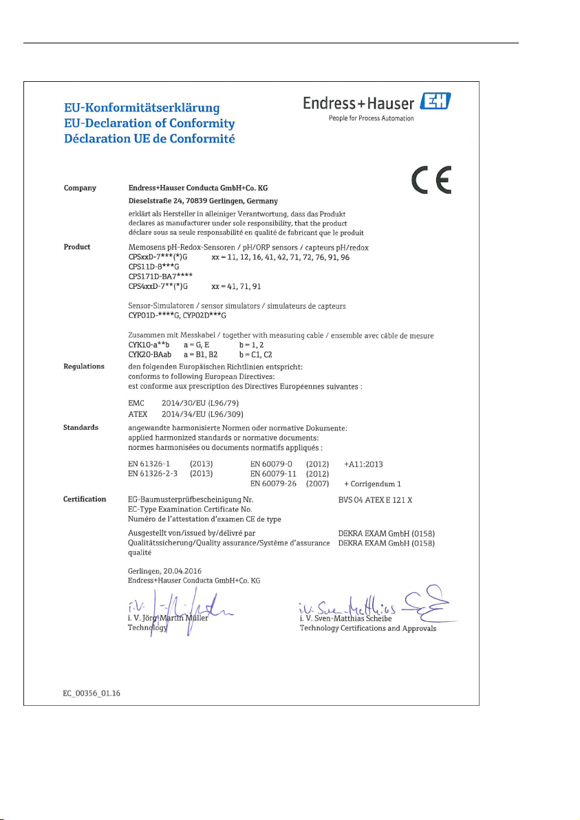
Konformitätserklärung
Endress+Hauser sichert mit dieser Konformitätserklärung zu, dass das Produkt mit den
Vorschriften der europäischen EMV-Richtlinie 2014/30/EU und der ATEX-Richtlinie
2014/34/EU übereinstimmt. Die Übereinstimmung wird durch die Einhaltung der in der
Konformitätserklärung aufgeführten Normen nachgewiesen.
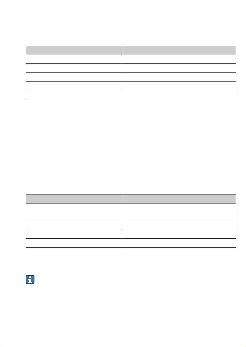
Zulassungen
IECEx
Ex ia IIC T3/T4/T6 Ga
ATEX
ATEX II 1G Ex ia IIC T3/T4/T6 Ga
10 Endress+Hauser
Page 11

CYK10/11 Warenannahme und Produktidentifizierung
FM / CSA
IS/NI CLI Div1&2 GP ABCD
NEPSI
II 1G Ex ia IIC T3/T4/T6 Ga
Temperaturklassen
Kabel Umgebungstemperaturbereich T
T3 T4 T6
CYK10-G**a, a = 1, 2
CYK10-I**a, a = 1, 2
Messkabel -15 °C ... 135 °C
(5 °F ... 275 °F)
-15 °C ... 120 °C
(5 °F ... 248 °F)
a
-15 °C ... 70 °C
(5 °C ... 158 °F)
Bei Einhaltung der angegebenen Umgebungstemperaturen treten am Kabel keine für die
jeweilige Temperaturklasse unzulässigen Temperaturen auf.
3.2.3 Lieferumfang Memosens-Kabel
• 1 Memosens-Kabel in bestellter Ausführung
• 1 Betriebsanleitung BA00118C/07/A2
CYK11-Verbindungsdose
• Verbindungsdose komplett, 6-fache Anschlussklemme, Kabelverschraubung und/oder
M12-Buchse
• Befestigungsplatte
• Schlauchschelle 40 ... 60 mm
Endress+Hauser 11
Page 12
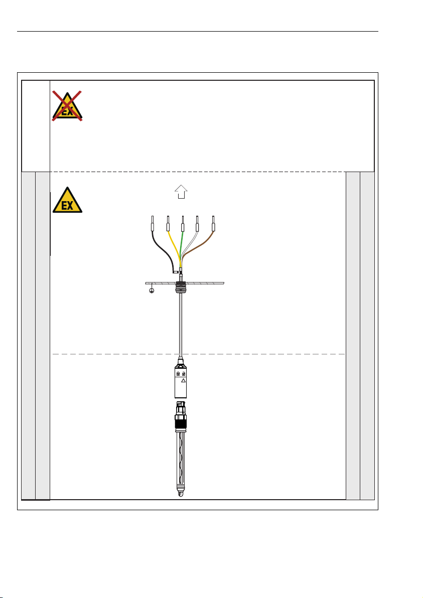
Anschlussschema (Ex-Bereich) CYK10/11
GN/YE
II 1G
CYK10-G/
CYK10-I
GND YE GN WH BN
Explosionsgefährdeter Bereich / Hazardous area
Nicht explosionsgef. /
hazardousnon
Zone 1
ComB ComA - +
Anschluss an zugelassene Messumformer/Connection to approved transmitters
II 2G
Kategorie / Category
Zone 0
ATEX zuglassene Sensoren gemäß/
ATEX approved sensors according to
BVS 04 ATEX E 121 X
IECEx zugelassene Sensoren gemäß/
IECEx approved sensors according to
BVS 11. 0052 X
4 Anschlussschema (Ex-Bereich)
1 Anschluss im explosionsgefährdeten Bereich
A0031034
12 Endress+Hauser
Page 13

CYK10/11 Montage
63 (2.48)
75 (2.95)
80 (3.15)
PK
85
GY
86
BN
87
WH
88
GN
97
YE
98
63 (2.48)
! 4.5 (4x)
80 (3.15)
52 (2.05)
70 (2.76)
80 (3.15)
63 (2.48)
52 (2.05)
5 Montage
5.1 CYK11-Verbindungsdose an eine Wand montieren
A0031086
2 Verbindungsdose, Abmessungen in mm (inch)
3 Befestigungsplatte, Abmessungen in mm (inch)
Montieren Sie die Verbindungsdose immer so, dass die Kabelzuführung von unten
erfolgt.
Die Montage erfolgt bei abgenommenem Frontdeckel.
Endress+Hauser 13
A0031076
Page 14

Elektrischer Anschluss CYK10/11
Schrauben Sie das Gehäuse der Verbindungsdose direkt an die Wand oder auf die
Befestigungsplatte. Die Befestigungsplatte kann als Bohrschablone verwendet werden.
5.2 CYK11-Verbindungsdose an ein Rohr montieren
Montieren Sie die Verbindungsdose immer so, dass die Kabelzuführung von unten
erfolgt.
1. Verschrauben Sie das Gehäuse mit der Befestigungsplatte. Damit ist eine Befestigung an
waagrechten oder senkrechten Rohren möglich.
2. Biegen Sie die Laschen an der Befestigungsplatte auf den ungefähren Durchmesser des
Halterohres. Befestigen Sie die Schlauchschelle am Rohr und klemmen Sie die Laschen
unter die Schelle.
A0031081
4 Rohrmontage mit Befestigungsplatte
6 Elektrischer Anschluss
WARNUNG
L
Gerät unter Spannung
Unsachgemäßer Anschluss kann zu Verletzungen oder Tod führen
Der elektrische Anschluss darf nur von einer Elektrofachkraft durchgeführt werden.
‣
Die Elektrofachkraft muss diese Betriebsanleitung gelesen und verstanden haben und muss
‣
die Anweisungen dieser Anleitung befolgen.
Stellen Sie vor Beginn der Anschlussarbeiten sicher, dass an keinem Kabel Spannung
‣
anliegt.
14 Endress+Hauser
Page 15

CYK10/11 Elektrischer Anschluss
GN/YE
YE
GN
BN
WH
GND
+
–
Com A
Com B
GY
GY
GY
GY
GN
GN
WH
WH
BN
BN
YE
YE
PK
PK
GND
-
Com A
-
+
Com B
+
{
{
1
2
6.1 CYK10 anschließen
6.1.1 CYK10 mit Aderendhülsen
A0031036
5 Elektrischer Anschluss, Aderendhülsen
Statt über GY kann auch über die Kabelschellen im Transmitter geerdet werden.
6.1.2 CYK10 mit M12-Stecker
A0018861
6 Elektrischer Anschluss, M12-Stecker
6.2 CYK11 anschließen
6.2.1 CYK11 mit Aderendhülsen
7 Elektrischer Anschluss, Aderendhülsen
1 Memosens-Sensor
2 Festkabel-Sensor
Endress+Hauser 15
A0031038
Page 16

Elektrischer Anschluss CYK10/11
GY
GN
WH
BN
YE
PK
1
2
GY
GN
WH
BN
YE
PK
GY
GN
WH
BN
YE
PK
GN/YE
1
6.2.2 CYK11 und Festkabelsensor
Die Kabelfarben entsprechen denen der Sensoren, sodass ein direktes Durchverkabeln möglich
ist.
Einige Festkabelsensoren arbeiten mit der Memosens-Betriebsspannung und werden
wie ein Memosens-Sensor angeschlossen (z.B. CLS50D). Überprüfen Sie vor der
Inbetriebnahme mit welcher Spannungsversorgung Ihr Sensor arbeitet und schließen Sie
den Sensor dementsprechend an.
A0031084
8 Elektrischer Anschluss, CYK11 und Festkabelsensor
1 CYK11
2 Festkabelsensor
6.2.3 CYK11 als Verlängerung für CYK10
Hier werden die Adern "GY" und "PK" nicht benötigt. Führen Sie diese auf potentialgetrennte
Klemmen.
Nicht offen in der Kabeldose belassen!
Die Schirme beider Kabel müssen verbunden werden. Bei der Verbindungsdose Kabel-Kabel
erfolgt dies automatisch über die Schirm-Kontaktierung in den Kabelverschraubungen.
A0031074
9 Elektrischer Anschluss, CYK11 als Verlängerung für CYK10
1 CYK11
16 Endress+Hauser
Page 17

CYK10/11 Elektrischer Anschluss
GY
WH
YE
PK
GN
BN
Com A
Com B
{
-
+
{
-
+
1
2
3
1
1
2
3
4
5
6
6.2.4 CYK11 mit Aderendhülse und M12-Buchse
A0031113
10 Elektrischer Anschluss, CYK11 mit Aderendhülse und M12-Buchse
1 Memosens-Sensor
2 Festkabel-Sensor
3 Memosens-Sensor über CYK10 mit M12-Stecker / Festkabelsensor
6.2.5 CYK11 mit M12-Stecker und M12-Buchse
A0031073
11 Elektrischer Anschluss, CYK11 mit M12-Stecker und M12-Buchse
1 Festkabelsensor / Memosens-Sensor über CYK10 mit M12
1
V
Festkabelsensor
2
GND
3
V
Memosens-Sensor
4
GND
5
RS 485 A (GN)
6
RS 485 B (YE)
12 Belegung M12-Stecker
Endress+Hauser 17
A0031043
(+24 V) (PK)
Festkabelsensor
(BN)
Memosens-Sensor
(GY)
(WH)
Page 18

Elektrischer Anschluss CYK10/11
PK
85
GY
86
BN
87
WH
88
GN
97
YE
98
1
2
A
B
3
4
6.3 CYK11-Verbindungsdose anschließen
13 Elektrischer Anschluss CYK11-Verbindungsdose M12-Buchse/Kabel
1 Kabelverschraubung - Schirm in Verschraubung geklemmt
2 Schirm
3 M12-Einbaubuchse
4 Abdeckung für M12-Einbaubuchse
A Messumformer
B Sensor
18 Endress+Hauser
A0031108
Page 19

CYK10/11 Elektrischer Anschluss
2
A
B
PK
85
GY
86
BN
87
WH
88
GN
97
YE
98
1
14 Elektrischer Anschluss CYK11-Verbindungsdose Kabel/Kabel
1 Kabelverschraubung - Schirm in Verschraubung geklemmt
2 Schirm
A Messumformer
B Sensor
A0031109
Kabelverschraubungen montieren
1. Schieben Sie das Anschlusskabel in die Kabelverschraubung, bis der Mantel an der
inneren Kontaktfeder anliegt.
2. Ziehen Sie die Kabelverschraubung zu (max. 3 Nm).
3. Verbinden Sie die Kabeladern.
Endress+Hauser 19
Page 20

Zubehör CYK10/11
7 Zubehör
Nachfolgend finden Sie das wichtigste Zubehör zum Ausgabezeitpunkt dieser
Dokumentation. Für Zubehör, das nicht hier aufgeführt ist, wenden Sie sich an Ihren
Service oder Ihre Vertriebszentrale.
Verbindungsdose M12-Buchse/Kabel
• Material: Aluminium, lackiert
• Kabelverlängerung: Memosens-Sensoren, Liquiline
• Best.-Nr.: 71145498
Verbindungsdose Kabel/Kabel
• Material: Aluminium, lackiert
• Kabelverlängerung: Memosens-Sensoren, Liquiline
• Best.-Nr.: 71145499
20 Endress+Hauser
Page 21

CYK10/11 Table of contents
Table of contents
1 Document information ........ 22
1.1 Warnings .......................... 22
1.2 Symbols ........................... 22
2 Basic safety instructions ...... 23
2.1 Requirements for personnel .......... 23
2.2 Designated use ..................... 23
2.3 Occupational safety ................. 23
2.4 Operational safety .................. 23
2.5 Product safety ...................... 24
3 Incoming acceptance and
product identification ......... 25
3.1 Incoming acceptance ................ 25
3.2 Product identification ................ 26
4 Connection diagram
(hazardous area) .............. 28
5 Installation .................... 29
5.1 Mounting the CYK11 junction box on a
wall ............................... 29
5.2 Mounting the CYK11 junction box on a
pipe .............................. 30
6 Electrical connection .......... 30
6.1 Connecting CYK10 .................. 31
6.2 Connecting CYK11 .................. 31
6.3 Connecting the CYK11 junction box .... 34
7 Accessories .................... 36
Endress+Hauser 21
Page 22

Document information CYK10/11
1 Document information
1.1 Warnings
Structure of information Meaning
DANGER
L
Causes (/consequences)
If necessary, Consequences of noncompliance (if applicable)
Corrective action
‣
WARNING
L
Causes (/consequences)
If necessary, Consequences of noncompliance (if applicable)
Corrective action
‣
CAUTION
L
Causes (/consequences)
If necessary, Consequences of noncompliance (if applicable)
Corrective action
‣
NOTICE
Cause/situation
If necessary, Consequences of noncompliance (if applicable)
Action/note
‣
This symbol alerts you to a dangerous situation.
Failure to avoid the dangerous situation will result in a fatal or serious injury.
This symbol alerts you to a dangerous situation.
Failure to avoid the dangerous situation can result in a fatal or serious injury.
This symbol alerts you to a dangerous situation.
Failure to avoid this situation can result in minor or more serious injuries.
This symbol alerts you to situations which may result in damage to property.
1.2 Symbols
Symbol Meaning
Additional information, tips
Permitted or recommended
Not permitted or not recommended
Reference to device documentation
Reference to page
Reference to graphic
Result of a step
22 Endress+Hauser
Page 23

CYK10/11 Basic safety instructions
2 Basic safety instructions
2.1 Requirements for personnel
• Installation, commissioning, operation and maintenance of the measuring system may be
carried out only by specially trained technical personnel.
• The technical personnel must be authorized by the plant operator to carry out the specified
activities.
• The electrical connection may be performed only by an electrical technician.
• The technical personnel must have read and understood these Operating Instructions and
must follow the instructions contained therein.
• Faults at the measuring point may only be rectified by authorized and specially trained
personnel.
Repairs not described in the Operating Instructions provided must be carried out only
directly at the manufacturer's site or by the service organization.
2.2 Designated use
The Memosens data cable CYK10 is used for measuring with digital sensors with Memosens
technology. The Memosens extension cable CYK11 is used to connect fixed cable sensors with
the Memosens protocol and to extend CYK10-based installations.
The CYK11 cable may not be used to extend CYK10-based measuring points in the
hazardous area. The use of continuous, non-extended CYK10 Memosens data cables is
recommended for measuring points in the hazardous area.
Use of the device for any purpose other than that described, poses a threat to the safety of
people and of the entire measuring system and is therefore not permitted.
The manufacturer is not liable for damage caused by improper or non-designated use.
2.3 Occupational safety
As the user, you are responsible for complying with the following safety conditions:
• Installation guidelines
• Local standards and regulations
• Regulations for explosion protection
2.4 Operational safety
1. Before commissioning the entire measuring point, verify that all connections are
correct. Ensure that electrical cables and hose connections are undamaged.
2. Do not operate damaged products, and safeguard them to ensure that they are not
operated inadvertently. Label the damaged product as defective.
3. If faults cannot be rectified:
Take the products out of operation and safeguard them to ensure that they are not
operated inadvertently.
Endress+Hauser 23
Page 24

Basic safety instructions CYK10/11
2.5 Product safety
2.5.1 State of the art
The product is designed to meet state-of-the-art safety requirements, has been tested, and
left the factory in a condition in which it is safe to operate. The relevant regulations and
European standards have been observed.
2.5.2 Electrical equipment in hazardous areas IECEx and ATEX
The Memosens inductive sensor cable connection system, consisting of:
• IECEx-/ ATEX-approved sensors
• Measuring cable CYK10-G**a, a = 1, 2
• Measuring cable CYK10-I**a, a = 1, 2
is approved for measuring applications in explosive atmospheres in accordance with
• IECEx design approval BVS 11.0052 X
• EC design approval BVS 04 ATEX E 121 X with amendments
The corresponding IECEx certificate and the EC Certificate of Conformity for ATEX are an
integral part of these Operating Instructions.
• The sensors and cables must not be operated under electrostatically critical process
conditions. Avoid strong steam or dust currents that act directly on the connection system.
• The Memosens measuring cable CYK10 and its plug-in head must be protected against
electrostatic charge if they pass through Ex zone 0.
• Hazardous area versions of Memosens cables have an orange/red ring.
• The maximum permitted cable length is 100 m.
• Compliance with the regulations for electrical installations in hazardous areas (EN/IEC
60079-14) is mandatory when using devices and sensors.
Pay attention to the ex-related safety instructions of the transmitter and sensors when
cabling.
IECEx
The approved digital sensors with Memosens technology may be connected with the following
IECEx-certified measuring cables
• CYK10
• or a Memosens measuring cable that is identical both in terms of design, device technology
and function
only to an IECEx-approved intrinsically safe sensor output circuit of the Liquiline M CM42
transmitter or alternatively to an IECEx-certified intrinsically safe Memosens sensor output
that complies with the following maximum values. In particular, the effective inner inductance
and the capacitance of the approved, intrinsically safe sensor output may not exceed the
values below:
1. Entity Parameters
U0 = 5.1 V U0 = 5.04 V
I0 = 130 mA I0 = 80 mA
24 Endress+Hauser
1)
2. Entity Parameters
1)
Page 25

CYK10/11 Incoming acceptance and product identification
1. Entity Parameters
P0 = 166 mW (linear output curve) P0 = 112 mW (trapezoid output curve)
Ci = 15 µF Ci = 14.1 µF
Li = 95 µH Li = 237.2 µH
1) Ex-relevant electrical connection parameters
1)
2. Entity Parameters
1)
ATEX
The approved digital sensors with Memosens technology may be connected with the following
measuring cables
• CYK10
• or a Memosens measuring cable that is identical both in terms of design, device technology
and function
only to the ATEX-approved intrinsically safe sensor output circuit of the Mycom S CPM153G... or Liquiline M CM42 transmitter or alternatively to an ATEX-certified, intrinsically safe
Memosens sensor output that complies with the following maximum values. In particular, the
effective inner inductance and the capacitance of the approved, intrinsically safe sensor
output may not exceed the values below:
1. Entity Parameters
U0 = 5.1 V U0 = 5.04 V
I0 = 130 mA I0 = 80 mA
P0 = 166 mW (linear output curve) P0 = 112 mW (trapezoid output curve)
Ci = 15 µF Ci = 14.1 µF
Li = 95 µH Li = 237.2 µH
1)
2. Entity Parameters
1) Ex-relevant electrical connection parameters
FM / CSA and Nepsi
Pay attention to the associated Operating Instructions of your transmitter.
3 Incoming acceptance and product identification
3.1 Incoming acceptance
1. Verify that the packaging is undamaged.
Notify your supplier of any damage to the packaging.
Keep the damaged packaging until the matter has been settled.
Endress+Hauser 25
Page 26

Incoming acceptance and product identification CYK10/11
2. Verify that the contents are undamaged.
Notify your supplier of any damage to the delivery contents.
Keep the damaged products until the matter has been settled.
3. Check the delivery for completeness.
Check it against the delivery papers and your order.
4. Pack the product for storage and transportation in such a way that it is protected
against impact and moisture.
The original packaging offers the best protection.
The permitted ambient conditions must be observed (see "Technical data").
If you have any questions, please contact your supplier or your local sales center.
3.2 Product identification
3.2.1 Nameplate
The nameplate provides you with the following information on your device:
• Manufacturer identification
• Order code
• Serial number
• Safety information and warnings
Compare the data on the nameplate with your order.
‣
3.2.2 Certificates and approvals
Declaration of conformity
This Endress+Hauser Declaration of Conformity serves to guarantee that the product complies
with the requirements of European Directive 2014/30/EU relating to electromagnetic
compatibility and ATEX Directive 2014/34/EU. Compliance is verified by adherence to the
standards listed in the Declaration of Conformity.
Approvals
IECEx
Ex ia IIC T3/T4/T6 Ga
ATEX
ATEX II 1G Ex ia IIC T3/T4/T6 Ga
FM/CSA
IS/NI CLI Div1&2 GP ABCD
NEPSI
II 1G Ex ia IIC T3/T4/T6 Ga
26 Endress+Hauser
Page 27

CYK10/11 Incoming acceptance and product identification
Temperature classes
Cable Ambient temperature range T
T3 T4 T6
CYK10-G**a, a = 1, 2
CYK10-I**a, a = 1, 2
Measuring cable -15 °C to 135 °C
(5 °F to 275 °F)
-15 °C to 120 °C
(5 °F to 248 °F)
a
-15 °C to 70 °C
(5 °C to 158 °F)
If ambient temperatures do not fall outside the ambient temperatures shown above, no invalid
temperatures for the particular temperature class will occur at the cable.
3.2.3 Scope of delivery Memosens cable
• 1 Memosens cable, version as ordered
• 1 Operating Instructions BA00118C/07/A2
CYK11 junction box
• Complete junction box, 6-position terminal, cable gland and/or M12 socket
• Securing plate
• Hose clip 40 to 60 mm
Endress+Hauser 27
Page 28

Connection diagram (hazardous area) CYK10/11
GN/YE
II 1G
CYK10-G/
CYK10-I
GND YE GN WH BN
Explosionsgefährdeter Bereich / Hazardous area
Nicht explosionsgef. /
hazardousnon
Zone 1
ComB ComA - +
Anschluss an zugelassene Messumformer/Connection to approved transmitters
II 2G
Kategorie / Category
Zone 0
ATEX zuglassene Sensoren gemäß/
ATEX approved sensors according to
BVS 04 ATEX E 121 X
IECEx zugelassene Sensoren gemäß/
IECEx approved sensors according to
BVS 11. 0052 X
4 Connection diagram (hazardous area)
1 Connection in hazardous areas
A0031034
28 Endress+Hauser
Page 29

CYK10/11 Installation
63 (2.48)
75 (2.95)
80 (3.15)
PK
85
GY
86
BN
87
WH
88
GN
97
YE
98
63 (2.48)
! 4.5 (4x)
80 (3.15)
52 (2.05)
70 (2.76)
80 (3.15)
63 (2.48)
52 (2.05)
5 Installation
5.1 Mounting the CYK11 junction box on a wall
A0031086
2 Junction box, dimensions in mm (inch)
3 Securing plate, dimensions in mm (inch)
Always mount the junction box in such a way that the cable is fed in from below.
The box is mounted with the front cover removed.
Endress+Hauser 29
A0031076
Page 30

Electrical connection CYK10/11
Screw the housing of the junction box directly on the wall or on the securing plate. The
securing plant can be used as a drilling template.
5.2 Mounting the CYK11 junction box on a pipe
Always mount the junction box in such a way that the cable is fed in from below.
1. Screw the housing to the securing plate. This makes it possible to secure the box to
horizontal or vertical pipes.
2. Bend the loops on the securing plate to match the approximate diameter of the
retaining pipe. Secure the hose clip on the pipe and fix the loops under the clip.
A0031081
4 Pipe mounting with securing plate
6 Electrical connection
WARNING
L
Device is live
Incorrect connection may result in injury or death
The electrical connection may be performed only by an electrical technician.
‣
The electrical technician must have read and understood these Operating Instructions and
‣
must follow the instructions contained therein.
Prior to commencing connection work, ensure that no voltage is present on any cable.
‣
30 Endress+Hauser
Page 31

CYK10/11 Electrical connection
GN/YE
YE
GN
BN
WH
GND
+
–
Com A
Com B
GY
GY
GY
GY
GN
GN
WH
WH
BN
BN
YE
YE
PK
PK
GND
-
Com A
-
+
Com B
+
{
{
1
2
6.1 Connecting CYK10
6.1.1 CYK10 with ferrules
A0031036
5 Electrical connection, ferrules
Instead of grounding via GY, it is also possible to ground the device via the cable clamps in the
transmitter.
6.1.2 CYK10 with M12 plug
A0018861
6 Electrical connection, M12 plug
6.2 Connecting CYK11
6.2.1 CYK11 with ferrules
7 Electrical connection, ferrules
1 Memosens sensor
2 Fixed cable sensor
Endress+Hauser 31
A0031038
Page 32

Electrical connection CYK10/11
GY
GN
WH
BN
YE
PK
1
2
GY
GN
WH
BN
YE
PK
GY
GN
WH
BN
YE
PK
GN/YE
1
6.2.2 CYK11 and fixed cable sensor
The cable colors correspond to those of the sensors so direct through-cabling is possible.
Some fixed cable sensors work with the Memosens operating voltage and are connected
like a Memosens sensor (e.g. CLS50D). Before commissioning, check which power supply
your sensor works with and connect the sensor accordingly.
A0031084
8 Electrical connection, CYK11 and fixed cable sensor
1 CYK11
2 Fixed cable sensor
6.2.3 CYK11 as extension for CYK10
The "GY" and "PK" wires are not required here. Route these to potentially isolated terminals.
Do not leave them exposed in the cable box!
The shields of both cables must be connected. In the case of the cable-cable junction box, this
is performed automatically via the shield contact in the cable glands.
A0031074
9 Electrical connection, CYK11 as extension for CYK10
1 CYK11
32 Endress+Hauser
Page 33

CYK10/11 Electrical connection
GY
WH
YE
PK
GN
BN
Com A
Com B
{
-
+
{
-
+
1
2
3
1
1
2
3
4
5
6
6.2.4 CYK11 with ferrule and M12 socket
A0031113
10 Electrical connection, CYK11 with ferrule and M12 plug
1 Memosens sensor
2 Fixed cable sensor
3 Memosens sensor via CYK10 with M12 plug / fixed cable sensor
6.2.5 CYK11 with M12 plug and M12 socket
A0031073
11 Electrical connection, CYK11 with M12 plug and M12 socket
1 Fixed cable sensor / Memosens sensor via CYK10 with M12
1
V
Fixed cable sensor
2
GND
3
V
Memosens sensor
4
GND
5
RS 485 A (GN)
6
RS 485 B (YE)
12 M12 plug assignment
Endress+Hauser 33
A0031043
(+24 V) (PK)
Fixed cable sensor
(BN)
Memosens sensor
(GY)
(WH)
Page 34

Electrical connection CYK10/11
PK
85
GY
86
BN
87
WH
88
GN
97
YE
98
1
2
A
B
3
4
6.3 Connecting the CYK11 junction box
13 Electrical connection of CYK11 junction box, M12 socket/cable
1 Cable gland - shield fixed in gland
2 Shielding
3 M12 built-in socket
4 Cover for M12 installation socket
A Transmitter
B Sensor
34 Endress+Hauser
A0031108
Page 35

CYK10/11 Electrical connection
2
A
B
PK
85
GY
86
BN
87
WH
88
GN
97
YE
98
1
14 Electrical connection of CYK11 junction box, cable/cable
1 Cable gland - shield fixed in gland
2 Shielding
A Transmitter
B Sensor
A0031109
Mounting the cable glands
1. Guide the connecting cable into the cable gland until the sheath is in contact with the
inner contacting spring.
2. Tighten the cable gland (max. 3 Nm).
3. Connect the cable cores.
Endress+Hauser 35
Page 36

Accessories CYK10/11
7 Accessories
The following are the most important accessories available at the time this
documentation was issued. For accessories not listed here, please contact your service or
sales office.
Junction box, M12 socket/cable
• Material: aluminum, painted
• Cable extension: Memosens sensors, Liquiline
• Order No.: 71145498
Junction box, cable/cable
• Material: aluminum, painted
• Cable extension: Memosens sensors, Liquiline
• Order No.: 71145499
36 Endress+Hauser
Page 37

Page 38

Page 39

Page 40

*71395993*
71395993
www.addresses.endress.com
 Loading...