

Page 1
Betriebsanleitung / Operating Instructions
MEMO SENS
CYK10/11
Memosens data cables
Deutsch→ ä 4
English→ ä 20
BA00118C/07/A2/02.12
71159658
Page 2

Hinweise zu dieser Anleitung
GEFAHR
!
WARNUNG
!
VORSICHT
!
HINWEIS
Warnhinweise und deren Bedeutung
Struktur, Signalwörter und Farbkennzeichnung der Warnhinweise folgen den Vorgaben in ANSI
Z535.6 ("Product safety information in product manuals, instructions and other collateral materials").
Struktur des Hinweises Bedeutung
Dieser Hinweis macht Sie auf eine gefährliche Situation
Ursache (/Folgen)
Ggf. Folgen der Missachtung
• Maßnahme zur Abwehr
Ursache (/Folgen)
Ggf. Folgen der Missachtung
• Maßnahme zur Abwehr
Ursache (/Folgen)
Ggf. Folgen der Missachtung
• Maßnahme zur Abwehr
Ursache/Situation
Ggf. Folgen der Missachtung
• Maßnahme/Hinweis
aufmerksam.
Wenn Sie die gefährliche Situation nicht vermeiden, wird dies
zum Tod oder zu schweren Verletzungen führen.
Dieser Hinweis macht Sie auf eine gefährliche Situation
aufmerksam.
Wenn Sie die gefährliche Situation nicht vermeiden, kann dies
zum Tod oder zu schweren Verletzungen führen.
Dieser Hinweis macht Sie auf eine gefährliche Situation
aufmerksam.
Wenn Sie die gefährliche Situation nicht vermeiden, kann dies zu
mittelschweren oder leichten Verletzungen führen.
Dieser Hinweis macht Sie auf Situationen aufmerksam, die zu
Sachschäden führen können.
Verwendete Symbole
1 Dieses Symbol steht für einen Querverweis auf eine bestimmte Seite (z.B. Seite 1).
È ä
2 Dieses Symbol steht für einen Querverweis auf eine bestimmte Abbildung (z.B. Abb. 2).
È å
Zusatzinformationen, Tipp
erlaubt bzw. empfohlen
verboten bzw. nicht empfohlen
Page 3

CYK10/11
Inhaltsverzeichnis / Table of contents
1 Sicherheitshinweise . . . . . . . . . 4
1.1 Anforderungen an das Personal . . . . . . . . . 4
1.2 Bestimmungsgemäße Verwendung . . . . . . . 4
1.3 Arbeitssicherheit . . . . . . . . . . . . . . . . . . . . 4
1.4 Betriebssicherheit . . . . . . . . . . . . . . . . . . . . 4
1.5 Produktsicherheit . . . . . . . . . . . . . . . . . . . . 5
1.6 Sicherheitshinweise für elektrische
Betriebsmittel in explosionsgefährdeten
Bereichen . . . . . . . . . . . . . . . . . . . . . . . . . 5
2 Identifizierung . . . . . . . . . . . . . 8
2.1 Gerätebezeichnung . . . . . . . . . . . . . . . . . . 8
2.2 Lieferumfang Memosens-Kabel . . . . . . . . . . 8
2.3 Lieferumfang CYK11-Verbindungsdose . . . . 8
2.4 Zertifikate und Zulassungen . . . . . . . . . . . . 9
3 Anschluss im Ex-Bereich auf
einen Blick . . . . . . . . . . . . . . . 10
4 Verdrahtung . . . . . . . . . . . . . . 11
4.1 Verdrahtung CYK10 . . . . . . . . . . . . . . . . . 11
4.2 Verdrahtung CYK11 . . . . . . . . . . . . . . . . . 11
4.3 Montage und Verdrahtung
CYK11-Verbindungsdose . . . . . . . . . . . . . 14
5 Zubehör . . . . . . . . . . . . . . . . . 18
6 Safety instructions . . . . . . . . . . 20
6.1 Requirements for personnel . . . . . . . . . . . . 20
6.2 Designated use . . . . . . . . . . . . . . . . . . . . . 20
6.3 Occupational safety . . . . . . . . . . . . . . . . . . 20
6.4 Operational safety . . . . . . . . . . . . . . . . . . . 20
6.5 Product safety . . . . . . . . . . . . . . . . . . . . . . 21
6.6 Safety instructions for electrical apparatus for
explosion-hazardous areas . . . . . . . . . . . . 21
7 Identification . . . . . . . . . . . . . . 24
7.1 Device designation . . . . . . . . . . . . . . . . . . 24
7.2 Scope of delivery Memosens cable . . . . . . 24
7.3 Scope of delivery CYK11 junction box . . . . 24
7.4 Certificates and approvals . . . . . . . . . . . . . 25
8 Quick wiring guide in hazardous
areas . . . . . . . . . . . . . . . . . . . . 26
9 Wiring . . . . . . . . . . . . . . . . . . . 27
9.1 Wiring of CYK10 . . . . . . . . . . . . . . . . . . . 27
9.2 Wiring of CYK11 . . . . . . . . . . . . . . . . . . . 27
9.3 Mounting and wiring of CYK11 junction
box . . . . . . . . . . . . . . . . . . . . . . . . . . . . . . 30
10 Accessories . . . . . . . . . . . . . . . 34
11 Anhang / Appendix . . . . . . . . 35
Endress+Hauser
Page 4

Sicherheitshinweise CYK10/11
1 Sicherheitshinweise
1.1 Anforderungen an das Personal
• Montage, Inbetriebnahme, Bedienung und Wartung der Messeinrichtung dürfen nur durch dafür
ausgebildetes Fachpersonal erfolgen.
• Das Fachpersonal muss vom Anlagenbetreiber für die genannten Tätigkeiten autorisiert sein.
• Der elektrische Anschluss darf nur durch eine Elektrofachkraft erfolgen.
• Das Fachpersonal muss diese Betriebsanleitung gelesen und verstanden haben und die Anweisungen
dieser Betriebsanleitung befolgen.
• Störungen an der Messstelle dürfen nur von autorisiertem und dafür ausgebildetem Personal behoben
werden.
Reparaturen, die nicht in der mitgelieferten Betriebsanleitung beschrieben sind, dürfen nur direkt
beim Hersteller oder durch die Serviceorganisation durchgeführt werden.
1.2 Bestimmungsgemäße Verwendung
Das Memosens-Datenkabel CYK10 wird zur Messung mit digitalen Sensoren mit Memosens-Technologie eingesetzt. Das Memosens-Verlängerungskabel CYK11 wird zum Anschluss von Festkabelsensoren mit Memosens-Protokoll und zur Anschlussverlängerung von CYK10-basierten Installationen verwendet.
Das Kabel CYK11 darf nicht zum Verlängern von CYK10-basierten Messstellen im explosionsgefährdeten Bereich verwendet werden.
Für Messstellen im explosionsgefährdeten Bereich wird die Verwendung von durchgehenden,
nicht verlängerten Memosens-Datenkabel CYK10 empfohlen.
Eine andere als die beschriebene Verwendung stellt die Sicherheit von Personen und der gesamten
Messeinrichtung in Frage und ist daher nicht zulässig.
Der Hersteller haftet nicht für Schäden, die aus unsachgemäßer oder nicht bestimmungsgemäßer Verwendung entstehen.
1.3 Arbeitssicherheit
Als Anwender sind Sie für die Einhaltung folgender Sicherheitsbestimmungen verantwortlich:
• Vorschriften zum Explosionsschutz
• Installationsvorschriften
• Lokale Normen und Vorschriften.
1.4 Betriebssicherheit
• Prüfen Sie vor der Inbetriebnahme der Gesamtmessstelle alle Anschlüsse auf ihre Richtigkeit. Stellen
Sie sicher, dass elektrische Kabel und Schlauchverbindungen nicht beschädigt sind.
• Nehmen Sie beschädigte Produkte nicht in Betrieb und schützen Sie diese vor versehentlicher Inbetriebnahme. Kennzeichnen Sie das beschädigte Produkt als defekt.
• Können Störungen nicht behoben werden, müssen Sie die Produkte außer Betrieb setzen und vor
versehentlicher Inbetriebnahme schützen.
4 Endress+Hauser
Page 5

CYK10/11 Sicherheitshinweise
1.5 Produktsicherheit
Das Produkt ist nach dem Stand der Technik betriebssicher gebaut und geprüft und hat das Werk in
sicherheitstechnisch einwandfreiem Zustand verlassen.
Die einschlägigen Vorschriften und europäischen Normen sind berücksichtigt.
1.6 Sicherheitshinweise für elektrische Betriebsmittel in explosionsgefährdeten Bereichen
1.6.1 IECEx und ATEX
Das induktive Sensor-Kabel-Verbindungssystem Memosens, bestehend aus:
• IECEx-/ ATEX -zugelassenen Sensoren
• Messkabel CYK10-G**a, a = 1, 2
• Messkabel CYK10-I**a, a = 1, 2
ist zugelassen für Messanwendungen in explosiver Atmosphäre entsprechend
a) IECEx Bauart-Zulassung BVS 11.0052 X
b) EG Bauart-Zulassung BVS 04 ATEX E 121 X mit Ergänzungen.
Das entsprechende IECEx-Zertifikat und die EG-Konformitätsbescheinigung für ATEX sind Bestandteil
dieser Betriebsanleitung.
• Sensor und Kabel dürfen nicht unter elektrostatisch kritischen Prozessbedingungen betrieben wer-
den. Unmittelbar auf das Verbindungssystem einwirkende starke Dampf- oder Staubströme müssen
vermieden werden.
• Das Memosens-Messkabel CYK10 bzw. OYK10-G und dessen Steckkopf müssen vor elektrostati-
schen Ladungen geschützt werden, wenn sie durch die Ex-Zone 0 führen.
• Ex-Ausführungen von Memosens-Kabeln sind durch einen orange-roten Ring gekennzeichnet.
• Die maximal zulässige Kabellänge beträgt 100 m.
• Die Vorschriften für elektrische Installationen in explosionsgefährdeten Bereichen
(EN/IEC 60079-14) müssen bei der Vewendungen von Geräten und Sensoren beachtet werden.
Beachten Sie die ex-relevanten Sicherheitshinweise des Messumformers und der Sensoren zur
Verkabelung.
Endress+Hauser 5
Page 6

Sicherheitshinweise CYK10/11
1.6.2 IECEx
Die zugelassenen digitalen Sensoren mit Memosens-Technologie dürfen mit den folgenden IECEx-zertifizierten Messkabeln
1. CYK10
2. oder einem baulich und in Gerätetechnik und Funktion identischem Memosens-Messkabel
nur an den IECEx-zugelassenen eigensicheren Sensor-Ausgangsstromkreis des Messumformers Liquiline M CM42 oder alternativ an einen IECEx-zertifizierten eigensicheren Memosens-Sensorausgang,
der die folgenden Maximalwerte einhält, angeschlossen werden. Insbesondere die effektive innere
Induktivität und die Kapazität des zugelassenen, eigensicheren Sensorausgangs dürfen die unten stehenden Werte nicht überschreiten:
1. Entity Parameters
U0 = 5,1 V U0 = 5,04 V
I0 = 130 mA I0 = 80 mA
P0 = 166 mW (Lineare Ausgabekennlinie) P0 = 112 mW (Trapezförmige Ausgabekennlinie)
Ci = 15 μFC
Li = 95 μΗ Li = 237,2 μΗ
1) Ex-relevante elektrische Anschlussparameter
1)
2. Entity Parameters
= 14,1 μF
i
1)
6 Endress+Hauser
Page 7
CYK10/11 Sicherheitshinweise
1.6.3 ATEX
Die zugelassenen digitalen Sensoren mit Memosens-Technologie dürfen mit den folgenden Messkabeln
1. CYK10
2. OYK10-G (BVS 09 ATEX E 068 X über DEKRA EXAM, Bochum, Deutschland)
3. oder einem baulich und in Gerätetechnik und Funktion identischem Memosens-Messkabel
nur an den ATEX-zugelassenen eigensicheren Sensor-Ausgangsstromkreis des Messumformers Mycom
S CPM153-G... oder Liquiline M CM42 oder alternativ an einen ATEX-zertifizierten, eigensicheren
Memosens-Sensorausgang, der die folgenden Maximalwerte einhält, angeschlossen werden. Insbesondere die effektive innere Induktivität und die Kapazität des zugelassenen, eigensicheren Sensorausgangs
dürfen die unten stehenden Werte nicht überschreiten:
1. Entity Parameter
U0 = 5,1 V U0 = 5,04 V
= 130 mA I0 = 80 mA
I
0
= 166 mW (Lineare Ausgabekennlinie) P0 = 112 mW (Trapezförmige Ausgabekennlinie)
P
0
= 15 μFC
C
i
= 95 μΗ Li = 237,2 μΗ
L
i
1) Ex-relevante elektrische Anschlussparameter
1)
2. Entity Parameter
= 14,1 μF
i
1)
1.6.4 FM / CSA und Nepsi
Beachten Sie die entsprechende Bedienungsanleitung Ihres Messumformers.
Endress+Hauser 7
Page 8

Identifizierung CYK10/11
2 Identifizierung
2.1 Gerätebezeichnung
2.1.1 Typenschild
Typenschilder finden Sie:
• als Ummantelung am Kabel
• auf der Verpackung
Folgende Informationen zu Ihrem Gerät können Sie dem Typenschild entnehmen:
• Herstelleridentifikation
• Bestellcode
• Seriennummer
• Sicherheits- und Warnhinweise
Vergleichen Sie die Angaben auf dem Typenschild mit Ihrer Bestellung.
Um die Ausführung Ihres Kabels zu erfahren, geben Sie den Bestellcode vom Typenschild in die
Suchmaske unter folgende Adresse ein:
www.products.endress.com/order-ident
2.2 Lieferumfang Memosens-Kabel
Im Lieferumfang sind enthalten:
• 1 Memosens-Kabel in bestellter Ausführung
• 1 Betriebsanleitung BA00118C/07/A2
2.3 Lieferumfang CYK11-Verbindungsdose
Im Lieferumfang sind enthalten:
• Dose komplett, 6-fache Anschlussklemme, Kabelverschraubung und/oder M12-Buchse
• Befestigungsplatte
• Schlauchschelle 40 ... 60 mm
8 Endress+Hauser
Page 9
CYK10/11 Identifizierung
2.4 Zertifikate und Zulassungen
Konformitätserklärung
Das Produkt erfüllt die Anforderungen der harmonisierten europäischen Normen.
Damit erfüllt es die gesetzlichen Vorgaben der EG-Richtlinien.
Der Hersteller bestätigt die erfolgreiche Prüfung des Produkts durch die Anbringung des
2.4.1 Zulassungen für CYK10
IECEx
Ex ia IIC T3/T4/T6 Ga
ATEX
II 1G Ex ia IIC T3/T4/T6 Ga
FM / CSA
IS/NI CLI Div1&2 GP ABCD
Nepsi
II 1G Ex ia IIC T3/T4/T6 Ga
2.4.2 Temperaturklassen
-Zeichens.
4
Kabel Umgebungstemperaturbereich T
T3 T4 T6
CYK10-G**a, a = 1, 2
CYK10-I**a, a = 1, 2
Messkabel -15 °C ... 135 °C
(5 °F ... 275 °F)
a
-15 °C ... 120 °C
(5 °F ... 248 °F)
-15 °C ... 70 °C
(5 °C ... 158 °F)
Bei Einhaltung der angegebenen Umgebungstemperaturen treten am Kabel keine für die jeweilige
Temperaturklasse unzulässigen Temperaturen auf.
Endress+Hauser 9
Page 10
Anschluss im Ex-Bereich auf einen Blick CYK10/11
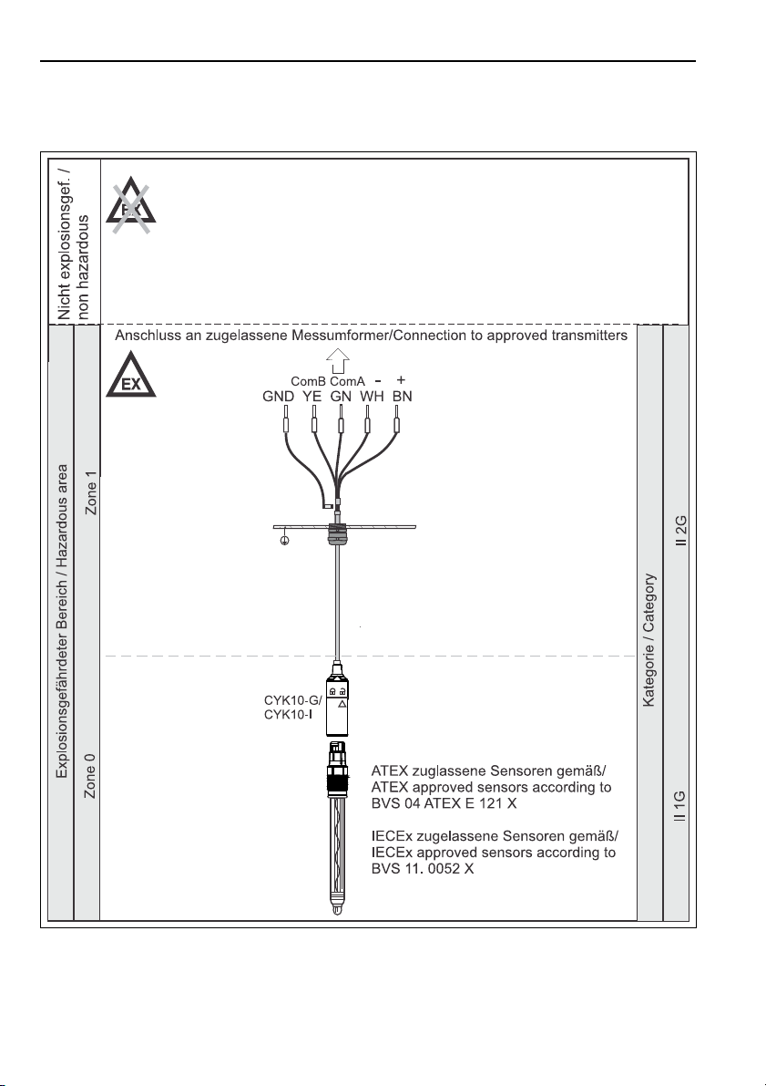
3 Anschluss im Ex-Bereich auf einen Blick
Abb. 1: Anschluss im explosionsgefährdeten Bereich
10 Endress+Hauser
a0018789
Page 11
CYK10/11 Verdrahtung
WARNUNG
!
4Verdrahtung
Gerät unter Spannung
Unsachgemäßer Anschluss kann zu Verletzungen oder Tod führen
• Der elektrische Anschluss darf nur von einer Elektrofachkraft durchgeführt werden.
• Die Elektrofachkraft muss diese Betriebsanleitung gelesen und verstanden haben und muss die
Anweisungen dieser Anleitung befolgen.
• Stellen Sie vor Beginn der Anschlussarbeiten sicher, dass an keinem Kabel Spannung anliegt.
4.1 Verdrahtung CYK10
a0003350
Statt über GY kann auch über die Kabelschellen im Transmitter geerdet werden.
CYK10 mit M12-Stecker
a0018861
4.2 Verdrahtung CYK11
CYK11 mit Aderendhülsen
a0015715-de
Endress+Hauser 11
Page 12

Verdrahtung CYK10/11
CYK11 und Festkabelsensor
Die Kabelfarben entsprechen denen der Sensoren, sodass ein direktes Durchverkabeln möglich ist.
Einige Festkabelsensoren arbeiten mit der Memosens-Betriebsspannung und werden wie ein
Memosens-Sensor angeschlossen (z.B. CLS50D). Überprüfen Sie vor der Inbetriebnahme mit welcher Spannungsversorgung Ihr Sensor arbeitet und schließen Sie den Sensor dementsprechend an.
a0016485-de
CYK11 als Verlängerung für CYK10
Hier werden die Adern "GY" und "PK" nicht benötigt. Sie sind auf getrennte Klemmsteine zu führen.
Nicht offen in der Kabeldose belassen!
Die Schirme beider Kabel müssen verbunden werden. Bei der Verbindungsdose Kabel-Kabel erfolgt dies
automatisch über die Schirm-Kontaktierung in den Kabelverschraubungen.
a0016486
CYK11 mit Aderendhülse und M12-Buchse
a0015716-de
12 Endress+Hauser
Page 13

CYK10/11 Verdrahtung
CYK11 mit M12-Stecker und M12-Buchse
a0016506-de
a0016913
Belegung M12-Stecker
1
V
GND
2
V
3
GND
4
RS 485 A (GN)
5
RS 485 B (YE)
6
Festkabelsensor
Memosens-Senso r
(+24 V) (PK)
Festkabelsensor
Memosens-Sensor
(GY)
(BN)
(WH)
Endress+Hauser 13
Page 14

Verdrahtung CYK10/11
4.3 Montage und Verdrahtung CYK11-Verbindungsdose
4.3.1 Montage CYK11-Verbindungsdose
Die Montage erfolgt bei abgenommenem Frontdeckel.
Wandmontage
Montieren Sie die Verbindungsdose immer so, dass die Kabelzuführung von unten erfolgt.
Schrauben Sie das Gehäuse der Verbindungsdose direkt an die Wand oder auf die Befestigungsplatte.
Die Befestigungsplatte kann als Bohrschablone verwendet werden.
Maße Befestigungsplatte
a0016243
14 Endress+Hauser
Page 15

CYK10/11 Verdrahtung
Rohrmontage
Montieren Sie die Verbindungsdose immer so, dass die Kabelzuführung von unten erfolgt.
Rohrmontage mit Befestigungsplatte
a0016244
1. Verschrauben Sie das Gehäuse mit der Befestigungsplatte. Damit ist eine Befestigung an waag-
rechten oder senkrechten Rohren möglich.
2. Biegen Sie die Laschen an der Befestigungsplatte auf den ungefähren Durchmesser des Halteroh-
res. Befestigen Sie die Schlauchschelle am Rohr und klemmen Sie die Laschen unter die Schelle.
Endress+Hauser 15
Page 16

Verdrahtung CYK10/11
4.3.2 Maße und Verdrahtung CYK11-Verbindungsdose
Maße und Verdrahtung CYK11-Verbindungsdose
M12-Buchse/Kabel
1
Kabelverschraubung - Schirm in Verschraubung
geklemmt
2
Schirm
3
M12-Einbaubuchse
4
Abdeckung für M12-Einbaubuchse
A
Messumformer
B
Sensor
a0016237
16 Endress+Hauser
Page 17

CYK10/11 Verdrahtung
Maße und Verdrahtung CYK11-Verbindungsdose
Kabel/Kabel
1
Kabelverschraubungen - Schirm in Verschraubung geklemmt
2
Schirm
A
Messumformer
B
Sensor
a0016238
Montage der Kabelverschraubungen:
1. Schieben Sie das Anschlusskabel in die Kabelverschraubung, bis der Mantel an der inneren Kon-
taktfeder anliegt.
2. Ziehen Sie die Kabelverschraubung zu (max. 3 Nm).
3. Verbinden Sie die Kabeladern.
Endress+Hauser 17
Page 18

Zubehör CYK10/11
5 Zubehör
Verbindungsdose M12-Buchse/Kabel
• Material: Aluminium, lackiert
• Kabelverlängerung: Memosens-Sensoren, Liquiline
• Best.-Nr.: 71145498
Verbindungsdose Kabel/Kabel
• Material: Aluminium, lackiert
• Kabelverlängerung: Memosens-Sensoren, Liquiline
• Best.-Nr.: 71145499
18 Endress+Hauser
Page 19

CYK10/11 Notes on these instructions
DANGER
!
WARNING
!
CAUTION
!
NOTICE
Notes on these instructions
Warnings
The structure, signal words and safety colors of the signs comply with the specifications of ANSI Z535.6
("Product safety information in product manuals, instructions and other collateral materials").
Safety message structure Meaning
This symbol alerts you to a dangerous situation.
Cause (/consequences)
Possible consequences if ignored
• Preventive measures
Cause (/consequences)
Possible consequences if ignored
• Preventive measures
Cause (/consequences)
Possible consequences if ignored
• Preventive measures
Cause/situation
Possible consequences if ignored
• Action/note
Failure to avoid the situation will result in a fatal or serious injury.
This symbol alerts you to a dangerous situation.
Failure to avoid the situation can result in a fatal or serious injury.
This symbol alerts you to a dangerous situation.
Failure to avoid this situation can result in minor or medium
injury.
This symbol alerts you to situations that can result in damage to
property and equipment.
Symbols used
1 This symbol indicates a cross reference to a defined page (e.g. p. 1).
È ä
2 This symbol indicates a cross reference to a defined figure (e.g. fig. 2).
È å
Additional information, tips
Permitted or recommended
Forbidden or not recommended
Endress+Hauser 19
Page 20

Safety instructions CYK10/11
6 Safety instructions
6.1 Requirements for personnel
• Installation, commissioning, operation and maintenance of the measuring system must only be
carried out by trained technical personnel.
• The technical personnel must be authorized by the plant operator to carry out the specified activities.
• The electrical connection may only be performed by an electrical technician.
• The technical personnel must have read and understood these Operating Instructions and must
follow the instructions they contain.
• Measuring point faults may only be rectified by authorized and specially trained personnel.
Repairs not described in the enclosed Operating Instructions may only be carried out directly at
the manufacturer's or by the service organization.
6.2 Designated use
The Memosens measuring cable CYK10 is designed for measurement with digital sensors with
Memosens technology. The Memosens extension cable CYK11 is used for connection of fixed cable
sensors with Memosens protocol and for connection extension of CYK10-based installations.
It is not allowed to use CYK11 as an extension for CYK10-based measuring system in hazardous
areas.
For hazardous areas it is recommended to use continuous and not extended Memosens measuring
cable CYK10.
Any other use than the one described here compromises the safety of persons and the entire measuring
system and is not permitted.
The manufacturer is not liable for damage caused by improper or non-designated use.
6.3 Occupational safety
As the user, you are responsible for complying with the following safety conditions:
• Guidelines for explosion protection
• Installation instructions
• Local prevailing standards and regulations.
6.4 Operational safety
• Prior to commissioning the entire measuring point, check that all connections are correct. Make sure
that electric cables and hose connections are not damaged.
• Do not commission damaged products. Protect them against unintentional startup. Label and identify
the damaged product as defective.
• If the faults cannot be eliminated, take the products out of service and protect them against unintentional startup.
20 Endress+Hauser
Page 21

CYK10/11 Safety instructions
6.5 Product safety
The product is designed to meet state-of-the-art safety requirements, has been tested and left the factory
in a condition in which it is safe to operate. Relevant regulations and European standards have been
observed.
6.6 Safety instructions for electrical apparatus for explosion-hazardous areas
The inductive Sensor-Cable-Connecting System Memosens, which consists of:
• IECEx / ATEX approved sensors with Memosens technology
• measuring cable CYK10-G**a, a = 1, 2
• measuring cable CYK10-I**a, a = 1, 2
is approved for measuring application in explosive atmospheres according to
a) IECEx Type Approval BVS 11. 0052 X
b) EC Type Approval BVS 04 ATEX E 121 X with supplements.
The corresponding IECEx certificate, respectively for ATEX the EC Conformity Declaration is part ofthis
document.
• It is not allowed to operate sensor and cable under electrostatic critical process conditions. Significant
steam and dust clouds acting directly on the connection system must be strictly avoided.
• The Memosens measuring cable CYK10-G, respectively OYK-10-G and its connecting head must be
protected from electrostatic charging, if installed through Ex-Zone 0.
• Ex-protected Memosens cable is indicated by an orange-red ring at the connecting head.
• Maximum permitted cable length is 100 m.
• The regulations for electrical installations in hazardous areas (EN/IEC 60079-14) are to be observed
for the use of instruments and sensors.
Observe ex-relevant safety instructions of transmitter and sensor for wiring.
Endress+Hauser 21
Page 22

Safety instructions CYK10/11
6.6.1 IECEx
The approved digital sensors with Memosens technology may be connected via the following measuring
cable
1. CYK10
2. or a structurally identical and in hardware and function identical and Memosens measuring cable
only to the IECEx approved intrinsic safe sensor output circuits of Transmitter Liquiline M CM42 or
alternatively to an IECEx certified, intrinsic safe Memosens sensor output providing the following maximum values as described below. In particular the effective inner inductivity and capacity of the approved, intrinsic safe sensor output must not exceed the values given below:
1. Entity Parameters 2. Entity Parameters
U0 = 5,1 V U0 = 5,04 V
I0 = 130 mA I0 = 80 mA
P0 = 166 mW (linear output characteristic) P0 = 112 mW (trapezoide output characteristic)
Ci = 15 μFC
Li = 95 μΗ Li = 237,2 μΗ
= 14,1 μF
i
22 Endress+Hauser
Page 23

CYK10/11 Safety instructions
6.6.2 ATEX
The approved digital sensors with Memosens technology may be connected via the following measuring
cable
1. CYK10
2. OYK10-G (approved by BVS 09 ATEX E 068 X per DEKRA EXAM, Bochum, Germany)
3. or a structurally identical and in hardware and function identical Memosens measuring cable
only to the approved intrinsic safe sensor output circuits of Transmitter Mycom S CPM153-G... or
Liquiline M CM42. or alternatively to an approved, intrinsic safe Memosens sensor output providing
the following maximum values as described below. In particular the effective inner inductivity and
capacity of the approved, intrinsic safe sensor output must not exceed the values given below:
1. Entity Parameters 2. Entity Parameters
= 5,1 V U0 = 5,04 V
U
0
= 130 mA I0 = 80 mA
I
0
= 166 mW (linear output characteristic) P0 = 112 mW (trapezoide output characteristic)
P
0
= 15 μFC
C
i
= 95 μΗ Li = 237,2 μΗ
L
i
= 14,1 μF
i
6.6.3 FM / CSA and Nepsi
Refer to the according Operating instructions of the used transmitter.
Endress+Hauser 23
Page 24

Identification CYK10/11
7 Identification
7.1 Device designation
7.1.1 Nameplate
Nameplates can be found:
• As jacket on the cable
• On the packaging
The nameplate provides you with the following information on your device:
• Manufacturer identification
• Order code
• Serial number
• Safety notices, warnings
Compare the data on the nameplate with your order.
To find out what cable version you have, enter the order code indicated on the nameplate in the
search screen at the following address:www.products.endress.com/order-ident
7.2 Scope of delivery Memosens cable
The delivery comprises:
• 1 Memosens cable in ordered version
• 1 Operating Instructions BA00118C/07/A2
7.3 Scope of delivery CYK11 junction box
The delivery comprises:
• Box complete, sixfold terminal, cable gland and/or M12 female connector
• Mounting plate
• Hose clip 40 ... 60 mm (1.57 ... 2.36 inch)
24 Endress+Hauser
Page 25

CYK10/11 Identification
7.4 Certificates and approvals
Declaration of Conformity
The product meets the requirements of harmonized European standards.It therefore meets the legal
specifications of EU guidelines.The manufacturer confirms that the product has been successfully tested
by applying the 4 mark.
7.4.1 Approvals for CYK10
IECEx
Ex ia IIC T3/T4/T6 Ga
ATEX
II 1G Ex ia IIC T3/T4/T6 Ga
FM / CSA
IS/NI CLI Div1&2 GP ABCD
Nepsi
II 1G Ex ia IIC T3/T4/T6 Ga
7.4.2 Temperature Classes
Cable Range of Ta for Temperature Class
T3 T4 T6
CYK10-G**a, a = 1, 2
CYK10-I**a, a = 1, 2
Measuring cable -15 °C ... 135 °C
(5 °F ... 275 °F)
-15 °C ... 120 °C
(5 °F ... 248 °F)
-15 °C ... 70 °C
(5 °C ... 158 °F)
If above shown ambient temperatures are not exceeded there will be no invalid temperatures on
the simulator according to the temperature class.
Endress+Hauser 25
Page 26

Quick wiring guide in hazardous areas CYK10/11
8 Quick wiring guide in hazardous areas
Abb. 2: Connection in explosion-hazardous areas
26 Endress+Hauser
a0018789
Page 27

CYK10/11 Wiring
WARNING
!
9Wiring
Device is energized
Improper connection can cause injury or death.
• The electrical connection must only be carried out by a certified electrician.
• Technical personnel must have read and understood the instructions in this manual and must
adhere to them.
• Prior to beginning any wiring work, make sure voltage is not applied to any of the cables.
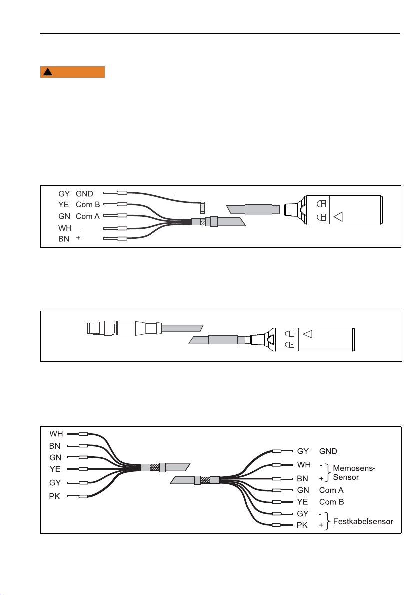
9.1 Wiring of CYK10
Fig. 3: Memosens data cable CYK10
Instead of GY you can also ground over the cable clamp in the transmitter.
CYK10 with M12 plug
9.2 Wiring of CYK11
CYK11 with ferrules
a0003350
a0018861
a0015715-en
Endress+Hauser 27
Page 28

Wiring CYK10/11
CYK11 and fixed cable sensor
The colors of the cable match those of the sensors. Direct cabling is possible.
Some fixed cable sensors work with the Memosens operating voltage and are connected in the
same way as a Memosens sensor (e.g. CLS50D). Before commissioning check your sensor´s power
supply and connect the sensor accordingly.
a0016485-en
CYK11 as extension for CYK10
The cores "GY" and "PK" are not required here. You must use a separate junction box or connection
panel to connect these cables. They must be terminated properly to avoid equipment damage!
The shields of both cables have to be connected. This is carried out automatically by the junction box
cable-to-cable through the shield contacting in the cable gland.
a0016486
CYK11 with ferrule and M12 female connector
a0015716-en
28 Endress+Hauser
Page 29

CYK10/11 Wiring
CYK11 with M12 plug and M12 female connector
a0016506-en
Assignment M12 plug
1
2
3
4
5
6
V
Fixed cable sensor
GND
V
Memosens sensor
GND
RS 485 A (GN)
RS 485 B (YE)
(+24 V) (PK)
Fixed cable sensor
(BN)
Memosens sensor
(GY)
(WH)
a0016913
Endress+Hauser 29
Page 30

Wiring CYK10/11
9.3 Mounting and wiring of CYK11 junction box
9.3.1 Installation of CYK11 junction box
The junction box is installed with the front cover removed.
Wall installation
The junction box must be installed such that the cables are introduced from below.
Mount the housing of the junction box directly to the wall or mounting plate. The mounting plate can
be used as a drilling template.
Dimensions of the mounting plate
a0016243
30 Endress+Hauser
Page 31

CYK10/11 Wiring
Pipe installation
The junction box must be installed such that the cables are introduced from below.
Pipe installation with mounting plate
a0016244
1. Screw the housing onto the mounting plate. It is possible to attach to horizontal or vertical pipes.
2. Bend the tabs on the mounting plate to the approximate diameter of the pipe. Attach the hose
clamp to the pipe and clip the tabs under the clamp.
Endress+Hauser 31
Page 32

Wiring CYK10/11
9.3.2 Dimensions and wiring of CYK11 junction box
Dimensions and wiring CYK11 junction box
M12 female connector/cable
1
Cable gland - Shield clamped in fitting
2
Shield
3
M12 panel jack
4
Cover for M12 panel jack
A
Transmitter
B
Sensor
a0016237
32 Endress+Hauser
Page 33

CYK10/11 Wiring
Dimensions and wiring CYK11 junction box
cable/cable
Cable gland - Shield clamped in fitting
1
Shield
2
Transmitter
A
Sensor
B
a0016238
Mounting the cable gland:
1. Guide the connecting cable into the cable gland until the jacket touches the inner contact spring.
2. Tighten the cable gland (max. 3 Nm).
3. Connect the cable wires.
Endress+Hauser 33
Page 34

Accessories CYK10/11
10 Accessories
Junction box M12 connector/cable
• Material: aluminum, painted
• Cable extension: Memosens sensors, Liquiline
• Order no. 71145498
Junction box cable/cable
• Material: aluminum, painted
• Cable extension: Memosens sensors, Liquiline
• Order no. 71145499
34 Endress+Hauser
Page 35

11 Anhang / Appendix
a0018790
Page 36

BA00118C/07/A2/02.12
Page 37

Anhang / Appendix
37
Page 38

Anhang / Appendix
38
Page 39

Anhang / Appendix
39
Page 40

Anhang / Appendix
40
 Loading...