

Page 1
BA01609C/07/A2/02.17
71386229
Products Solutions Services
Operating Instructions
ISFET sensors
Memosens-Sensoren und analoge Sensoren zur
pH-Messung
Memosens sensors and analog sensors for pH
measurement
Page 2

Page 3

ISFET sensors Table of contents
Table of contents
1 Hinweise zum Dokument ...... 4
2 Bestimmungsgemäße
Verwendung .................... 4
3 Versand und Lagerung ......... 4
4 Montage ......................... 5
4.1 Einbauwinkel ........................ 5
4.2 Sensorausrichtung ................... 5
5 Energieversorgung ............. 7
6 Kalibrieren und Messen ........ 7
7 Reinigung ....................... 9
8 Document information ........ 10
9 Designated use ................ 10
10 Transport and storage ........ 10
11 Installation .................... 11
11.1 Installation angle ................... 11
11.2 Sensor orientation .................. 11
12 Power supply .................. 13
13 Calibration and
measurement .................. 13
14 Cleaning ....................... 15
Endress+Hauser 3
Page 4

Hinweise zum Dokument ISFET sensors
1 Hinweise zum Dokument
In Ergänzung zu dieser Betriebsanleitung finden Sie auf den Produktseiten im Internet
folgende Anleitungen:
• Technische Information des jeweiligen Sensors
• Betriebsanleitung des verwendeten Messumformers
Sensoren für den explosionsgeschützten Bereich ist zusätzlich zu dieser Betriebsanleitung eine
XA "Sicherheitshinweise für den explosionsgeschützten Bereich" beigelegt.
Hinweise beim Einsatz im explosionsgeschützten Bereich zwingend beachten.
‣
Sicherheitshinweise für elektrische Betriebsmittel im explosionsgeschützten Bereich,
Memosens pH/ORP, XA00376C/07/A3
Sicherheitshinweise für elektrische Betriebsmittel im explosionsgeschützten Bereich,
analoge ISFET-pH-Sensoren, XA00352C/07/A3
2 Bestimmungsgemäße Verwendung
Die Sensoren sind zur kontinuierlichen Messung des pH-Werts in Flüssigkeiten bestimmt.
Eine Liste empfohlener Anwendungen finden Sie in der jeweiligen Technischen
Information des Sensors.
Eine andere als die beschriebene Verwendung stellt die Sicherheit von Personen und der
gesamten Messeinrichtung in Frage und ist daher nicht zulässig.
Der Hersteller haftet nicht für Schäden, die aus unsachgemäßer oder nicht
bestimmungsgemäßer Verwendung entstehen.
3 Versand und Lagerung
Alle Sensoren werden stückgeprüft und einzeln verpackt geliefert.
‣
Die Lagerung soll in trockenen Räumen bei 0 ... 50 °C (32 ... 120 °F) erfolgen.
‣
4 Endress+Hauser
Page 5
ISFET sensors Montage
A
B
4 Montage
4.1 Einbauwinkel
ISFET-Sensoren können in jeder Lage eingebaut werden, da keine flüssige Innenableitung
vorhanden ist. Allerdings ist nicht auszuschließen, dass bei Überkopfeinbau eine eventuell
vorhandene Luftblase
Diaphragma unterbricht.
1)
im Referenzsystem den elektrischen Kontakt zwischen Medium und
Der Sensor soll max. 6 Stunden im
eingebauten Zustand trocken stehen
(gilt auch für Überkopfeinbau).
Beachten Sie auch die in der
Betriebsanleitung der verwendeten
Armatur angegebenen Hinweise zum
Einbau.
A0030407
1 Einbauneigung
A Empfohlen
B Erlaubt, Randbedingungen beachten!
1) Der Sensor wird ab Werk luftblasenfrei ausgeliefert. Luftblasen entstehen aber durch Arbeiten mit Unterdruck,
z.B. beim Entleeren eines Tanks.
4.2 Sensorausrichtung
1. Beim Einbau des Sensors die Fließrichtung des Mediums beachten.
2. ISFET-Chip in einen Winkel von ca. 30 ... 45° zur Fließrichtung (Pos. 4) bringen.
Durch den drehbaren Anschlusskopf ist dies leicht zu realisieren.
Endress+Hauser 5
Page 6

Montage ISFET sensors
z
y
1
2
z
y
08156767
08156768
30...45 °
x
z
y
1
3
5
4
A0030427
2 Sensorausrichtung,
Vorderansicht
1 Eingravierte Seriennummer
2 Aufgedrucktes Typenschild
A0030428
3 Sensorausrichtung, 3D-Ansicht
1 Eingravierte Seriennummer
3 Drehbarer Teil des Anschlusskopfes
4 Fließrichtung des Mediums
5 ISFET-Chip
Wenn Sie den Sensor in eine Armatur einbauen, haben Sie zur Ausrichtung die eingravierte
Serienummer am Anschlusskopf zur Orientierung. Die Gravur befindet sich immer in einer
Ebene mit dem ISFET-Chip und mit dem Typenschild (z-y-Richtung, → 2).
ISFET-Sensoren sind nicht zum Einsatz in abrasiven Medien vorgesehen. Wenn Sie sie
dennoch in solchen Anwendungen einsetzen, müssen Sie vermeiden, den Chip direkt
anzuströmen. Sie verlängern dadurch die Lebensdauer und verbessern das Driftverhalten
des Sensors. Aber Sie haben dann den Nachteil, dass die Anzeige des pH-Wertes nicht
stabil ist.
6 Endress+Hauser
Page 7

ISFET sensors Energieversorgung
YE
GN
BN
WH
GND
+
–
Com A
Com B
GY
RD
GN
WH
YE
BN
Shield
BK
BK
SRC
DRN
PT1000
PT1000
PT1000
PM
GND
5 Energieversorgung
Memosens-Sensoren Analoge Sensoren
4 Messkabel CYK10 oder CYK20
5 Messkabel CPK12
SRC Source
DRN Drain
PM Potential Matching, PAL
GND Ground, PE
6 Kalibrieren und Messen
Zum Kalibrieren und Messen: Schutzkappe abnehmen.
‣
Trocken gelagerte ISFET-Sensoren müssen vor Gebrauch mindestens 15 Minuten
‣
gewässert werden. Nach dem Einschalten der Messeinrichtung wird ein Regelkreis
aufgebaut. Der Messwert stellt sich in dieser Zeit (ca. 5 bis 8 Minuten) auf den realen Wert
ein. Dieses Einschwingverhalten tritt nach jeder Unterbrechung des Flüssigkeitsfilms
zwischen pH-sensitivem Halbleiter und Referenzableitung auf. Die jeweilige Einschwingzeit
hängt von der Dauer der Unterbrechung ab.
Wenn zur Aufbewahrung des Sensors nicht mehr die Schutzkappe verwendet wird: Sensor
‣
in einer KCl-Lösung (3 mol/l) oder Pufferlösung aufbewahren.
Sensor nicht in destilliertem Wasser aufbewahren!
‣
Die Häufigkeit einer Kalibrierung oder Kontrolle des Sensors ist von den
‣
Einsatzbedingungen (Verschmutzung, chemische Belastung) abhängig.
Bei ISFET-Sensoren ist eine Zweipunkt-Kalibrierung erforderlich. Qualitätspuffer von
‣
Endress+Hauser, z. B. CPY20, verwenden.
Analoge ISFET-Sensoren: Beim Neuanschluss unbedingt kalibrieren.
‣
ISFET-Sensoren mit Memosens-Technologie müssen beim Neuanschluss nicht kalibriert
werden. Die Kalibrierung ist nur erforderlich bei besonders hohen Anforderungen an die
Messgenauigkeit oder bei Lagerung des Sensors länger als drei Monate.
Endress+Hauser 7
Page 8

Kalibrieren und Messen ISFET sensors
1. Sensor in eine definierte Pufferlösung tauchen (z. B. pH 7).
Bei symmetrischem Anschluss (b) auch die Potenzialausgleichsleitung (PAL) eintauchen. Bei
unsymmetrischem Anschluss ein Kabel ohne PAL verwenden oder PAL direkt hinter dem
Schrumpfschlauch abschneiden.
Bei ISFET-Sensoren mit Memosens-Technologie (a) ist kein Anschluss mit PAL
notwendig.
2. Kalibrierung am Messgerät vornehmen:
(a) Bei pH-Sensoren und manueller Temperaturkompensation Messtemperatur einstellen.
(b) pH-Wert der Pufferlösung eingeben.
(c) Kalibrierung starten.
(d) Nach Stabilisierung wird der Wert übernommen.
3. Sensor mit destilliertem Wasser abspülen. Nicht abtrocknen!
4. ISFET-Sensor in die zweite Pufferlösung (z. B. pH 4) tauchen.
5. Kalibrierung am Messgerät vornehmen:
(a) pH-Wert der zweiten Pufferlösung eingeben.
(b) Kalibrierung starten.
(c) Nach Stabilisierung wird der Wert übernommen.
Das Gerät berechnet den Arbeitspunkt und die Steilheit und zeigt sie an. Nach der Übernahme
der Werte zur Justage ist das Gerät an den neuen ISFET-Sensor angepasst.
8 Endress+Hauser
Page 9

ISFET sensors Reinigung
6. ISFET-Sensor mit destilliertem Wasser abspülen.
7 Reinigung
Verschmutzungen am Sensor reinigen Sie je nach Art der Verschmutzung:
1. Ölige und fettige Beläge:
Reinigen mit Fettlöser, z. B. Alkohol, evtl. heißes Wasser und tensidhaltige (alkalische)
Mittel (z.B. Spülmittel).
2. Kalk-, Cyanid-, Metallhydroxid- und schwer lösliche organische Beläge:
Beläge mit verdünnter Salzsäure (3 %) lösen, anschließend sorgfältig mit viel klarem
Wasser spülen.
3.
4. Eiweißhaltige Beläge (z. B. Lebensmittelindustrie):
5.
WARNUNG
L
Thioharnstoff
Gesundheitsschädlich beim Verschlucken. Verdacht auf krebserzeugende Wirkung.
Kann das Kind im Mutterleib möglicherweise schädigen. Umweltgefährlich mit
langfristiger Wirkung.
Tragen Sie Schutzbrille, Schutzhandschuhe und entsprechende Schutzkleidung.
‣
Vermeiden Sie jeden Kontakt mit Augen, Mund und Haut.
‣
Vermeiden Sie das Freisetzen in die Umwelt.
‣
Sulfidhaltige Beläge (aus REA oder Kläranlagen):
Mischung aus Salzsäure (3 %) und Thioharnstoff (handelsüblich) verwenden,
anschließend sorgfältig mit viel klarem Wasser spülen.
Mischung aus Salzsäure (0,5 %) und Pepsin (handelsüblich) verwenden, anschließend
sorgfältig mit viel klarem Wasser spülen.
HINWEIS
Dichtungsschäden durch Druckwasser
Druckwasser nicht direkt auf den Chip richten.
‣
Fasern, suspendierte Stoffe:
Druckwasser, eventuell mit Netzmitteln.
6. Leicht lösliche biologische Beläge:
Mit Druckwasser spülen.
Endress+Hauser 9
Page 10

Document information ISFET sensors
8 Document information
The following manuals which complement these Operating Instructions can be found on the
product pages on the Internet:
• Technical Information for the relevant sensor
• Operating Instructions for the transmitter used
In addition to these Operating Instructions, an XA with "Safety instructions for the hazardous
area" is also included with sensors for use in the hazardous area.
Please follow instructions on use in the hazardous area carefully.
‣
Safety instructions for electrical apparatus in hazardous areas, Memosens pH/ORP,
XA00376C/07/A3
Safety instructions for electrical apparatus in hazardous areas, analog ISFET pH sensors,
XA00352C/07/A3
9 Designated use
The sensors are designed for the continuous measurement of the pH value in liquids.
A list of recommended applications is provided in the Technical Information for the
relevant sensor.
Use of the device for any purpose other than that described, poses a threat to the safety of
people and of the entire measuring system and is therefore not permitted.
The manufacturer is not liable for damage caused by improper or non-designated use.
10 Transport and storage
All sensors are individually tested and supplied in individual packs.
‣
They should be stored in a dry place at temperatures of between 0 and 50 °C (32 to 120 °F).
‣
10 Endress+Hauser
Page 11

ISFET sensors Installation
A
B
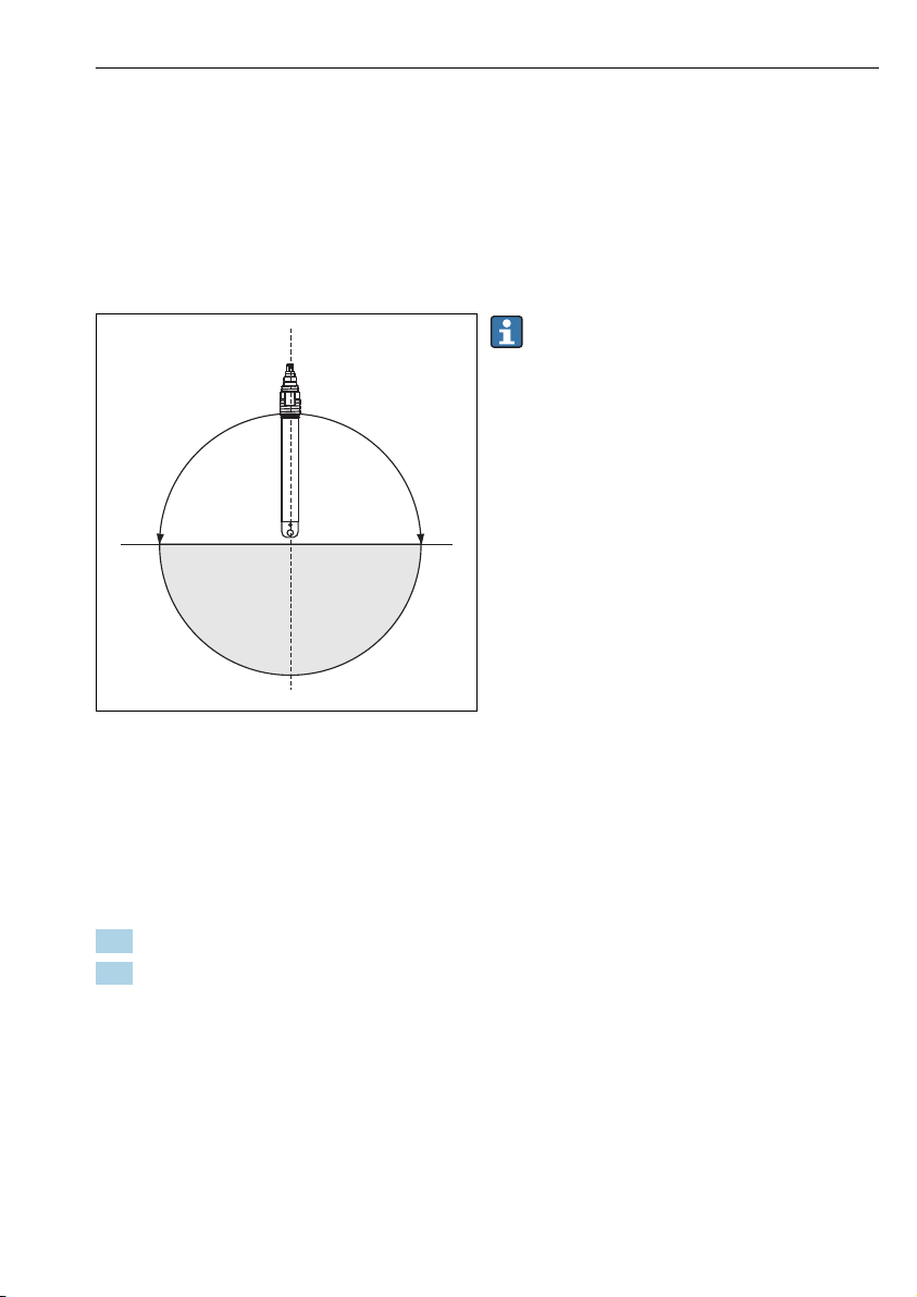
11 Installation
11.1 Installation angle
ISFET sensors can be installed in any position because there is no liquid inner lead. However,
in the event of upside-down installation an air bubble
1)
may form in the reference system and
interrupt the electrical contact between the medium and the junction.
The installed sensor should remain in
dry conditions for a maximum of 6
hours (also applies to upside-down
installation).
Make sure to follow the installation
instructions in the Operating
Instructions of the used assembly.
A0030407
6 Angle of installation
A Recommended
B Permitted, please pay careful attention to basic
conditions!
1) The sensor is free of air bubbles when delivered from the factory. Air bubbles occur, however, when working with
negative pressure, e.g. when emptying a tank.
11.2 Sensor orientation
1. Note the direction of medium flow when installing the sensor.
2. Position the ISFET chip so that it is at an angle of approx. 30 to 45° in relation to the
direction of flow (item 4).
This is easily achieved with the rotatable terminal head.
Endress+Hauser 11
Page 12

Installation ISFET sensors
z
y
1
2
z
y
08156767
08156768
30...45 °
x
z
y
1
3
5
4
A0030428
7 Sensor orientation, front view
1 Engraved serial number
2 Imprinted nameplate
8 Sensor orientation, 3D view
1 Engraved serial number
3 Rotatable part of the terminal head
A0030427
4 Direction of medium flow
5 ISFET chip
When you install the sensor in an assembly, use the serial number engraved on the terminal
head for correct sensor orientation. The engraving is always on the same plane as the ISFET
chip and the nameplate (z-y direction,→ 7).
ISFET sensors are not designed for use in abrasive media. However, if you do use them in
such applications make sure to avoid direct flow to the chip. This extends the sensor
operating life and improves the drift behavior of the sensor. However it does have the
disadvantage that the pH value display is not stable.
12 Endress+Hauser
Page 13

ISFET sensors Power supply
YE
GN
BN
WH
GND
+
–
Com A
Com B
GY
RD
GN
WH
YE
BN
Shield
BK
BK
SRC
DRN
PT1000
PT1000
PT1000
PM
GND
12 Power supply
Memosens sensors Analog sensors
9 Measuring cable CYK10 or CYK20
10 Measuring cable CPK12
SRC Source
DRN Drain
PM Potential matching, PML
GND Ground, PE
13 Calibration and measurement
Remove the protection cap for calibration and measurement.
‣
ISFET sensors which are stored dry must be immersed in water for at least 15 minutes
‣
before use. A closed-control loop is created when the measuring system is switched on. The
measured value adjusts to the real value during this time (approx. 5 to 8 minutes). This
settling behavior occurs every time the film of liquid between the pH-sensitive
semiconductor and the reference lead is interrupted. The settling time depends on the
length of the interruption.
If the protection cap is no longer used to store the sensor, store the sensor in a KCl solution
‣
(3 mol/l) or buffer solution.
Do not store the sensor in distilled water!
‣
The frequency at which a sensor calibration or sensor inspection is performed depends on
‣
the operating conditions (fouling, chemical load).
Two-point calibration is required for ISFET sensors. Use quality buffer from
‣
Endress+Hauser, e.g. CPY20.
Analog ISFET sensors must be calibrated when they are connected for the first time.
‣
ISFET sensors with Memosens technology do not need to be calibrated when they are
connected for the first time. Calibration is only required if very strict accuracy
requirements must be met or if the sensor has been in storage for longer than three
months.
Endress+Hauser 13
Page 14

Calibration and measurement ISFET sensors
1. Immerse the sensor into a defined buffer solution (e.g. pH 7).
In the case of a symmetrical connection (b), also immerse the potential matching line (PML)
into the solution. In the case of an asymmetrical connection, use a cable without a PML or cut
off the PML directly after the heat shrink tube.
Connection with a PML is not necessary for ISFET sensors with Memosens technology.
2. Perform the calibration at the measuring device:
(a) In the case of pH sensors and manual temperature compensation, set the measurement
temperature.
(b) Enter the pH value of the buffer solution.
(c) Start calibration.
(d) The value is accepted once it has stabilized.
3. Rinse the sensor with distilled water. Do not dry the sensor!
4. Immerse the ISFET sensor into the second buffer solution (e.g. pH 4).
5. Perform the calibration at the measuring device:
(a) Enter the pH value of the second buffer solution.
(b) Start the calibration.
(c) The value is accepted once it has stabilized.
The device calculates the operating point and slope and displays the values. Once the
adjustment values have been accepted, the device is adjusted to the new ISFET sensor.
14 Endress+Hauser
Page 15

ISFET sensors Cleaning
6. Rinse the ISFET sensor with distilled water.
14 Cleaning
Clean away fouling on the sensor as follows depending on the type of fouling:
1. Oily and greasy films:
Clean with grease remover, e.g. alcohol, as well as hot water and (alkaline) agents
containing surfactants (e.g. dishwashing detergent).
2. Lime, cyanide and metal hydroxide buildup and low solubility organic buildup:
Dissolve buildup with diluted hydrochloric acid (3 %) and then rinse thoroughly with
plenty of clear water.
3.
4. Buildup containing proteins (e.g. food industry):
5.
WARNING
L
Thiocarbamide
Harmful if swallowed. Limited evidence of carcinogenicity. Possible risk of harm to the
unborn child. Dangerous for the environment with long-term effects.
Wear protective goggles, protective gloves and appropriate protective clothing.
‣
Avoid all contact with the eyes, mouth and skin.
‣
Avoid releases into the environment.
‣
Sulfidic buildup (from flue gas desulfurization or sewage treatment plants):
Use a mixture of hydrochloric acid (3 %) and thiocarbamide (commercially available)
and then rinse thoroughly with plenty of clear water.
Use a mixture of hydrochloric acid (0.5 %) and pepsin (commercially available) and then
rinse thoroughly with plenty of clear water.
NOTICE
Pressurized water can damage the seal
Do not direct pressurized water straight onto the chip.
‣
Fibers, suspended substances:
Pressurized water, possibly with surface-active agents.
6. Readily soluble biological buildup:
Rinse with pressurized water.
Endress+Hauser 15
Page 16

*71386229*
71386229
www.addresses.endress.com
 Loading...