

Page 1
0
BA00468C/07/EN/14.16
71332820
Products Solutions Services
Operating Instructions
Ceramax CPS341D
Sensor with pH-sensitive enamel and digital
Memosens technology
Page 2

Page 3

Table of contents
1 Document information ......... 4
1.1 Warnings ........................... 4
1.2 Symbols ............................ 4
2 Basic safety instructions ....... 5
2.1 Requirements for personnel ........... 5
2.2 Designated use ...................... 5
2.3 Occupational safety .................. 5
2.4 Operational safety ................... 5
2.5 Product safety ....................... 6
3 Product description ............. 6
4 Incoming acceptance and
product identification .......... 8
4.1 Incoming acceptance ................. 8
4.2 Product identification ................. 8
4.3 Scope of delivery ..................... 9
4.4 Certificates and approvals ............. 9
5 Installation .................... 10
5.1 Installation conditions ............... 10
5.2 Mounting the sensor ................ 11
Table of contents
11 Accessories .................... 25
11.1 CPS341Z .......................... 25
11.2 Buffer solutions .................... 26
11.3 Cable ............................. 26
12 Technical data ................. 27
Index ................................. 29
6 Electrical connection .......... 13
6.1 Connecting the sensor ............... 13
6.2 Connecting the optional electrolyte
monitor ........................... 14
7 Commissioning ................ 15
7.1 Disinfecting the electrolyte system ..... 15
7.2 Regenerating the sensor ............. 17
7.3 Filling the electrolyte vessel .......... 18
7.4 Calibrating/adjusting the sensor ...... 19
8 Diagnostics and
troubleshooting ............... 20
9 Maintenance .................. 21
9.1 Changing the electrolyte bottle ........ 21
9.2 Clean sensor ....................... 23
10 Repairs ......................... 25
10.1 Spare parts ........................ 25
10.2 Return ............................ 25
10.3 Disposal ........................... 25
Endress+Hauser 3
Page 4
Document information Ceramax CPS341D
1 Document information
1.1 Warnings
Structure of information Meaning
DANGER
L
Causes (/consequences)
Consequences of non-compliance (if
applicable)
Corrective action
‣
WARNING
L
Causes (/consequences)
Consequences of non-compliance (if
applicable)
Corrective action
‣
CAUTION
L
Causes (/consequences)
Consequences of non-compliance (if
applicable)
Corrective action
‣
NOTICE
Cause/situation
Consequences of non-compliance (if
applicable)
Action/note
‣
This symbol alerts you to a dangerous situation.
Failure to avoid the dangerous situation will result in a fatal or serious injury.
This symbol alerts you to a dangerous situation.
Failure to avoid the dangerous situation can result in a fatal or serious injury.
This symbol alerts you to a dangerous situation.
Failure to avoid this situation can result in minor or more serious injuries.
This symbol alerts you to situations which may result in damage to property.
1.2 Symbols
Symbol Meaning
Additional information, tips
Permitted or recommended
Not permitted or not recommended
Reference to device documentation
Reference to page
Reference to graphic
Result of a step
4 Endress+Hauser
Page 5

Ceramax CPS341D Basic safety instructions
2 Basic safety instructions
2.1 Requirements for personnel
• Installation, commissioning, operation and maintenance of the measuring system may be
carried out only by specially trained technical personnel.
• The technical personnel must be authorized by the plant operator to carry out the specified
activities.
• The electrical connection may be performed only by an electrical technician.
• The technical personnel must have read and understood these Operating Instructions and
must follow the instructions contained therein.
• Measuring point faults may be repaired only by authorized and specially trained personnel.
Repairs not described in the Operating Instructions provided may only be carried out
directly by the manufacturer or by the service organization.
2.2 Designated use
The sensor is designed for the continuous measurement of the pH value in liquids.
Recommended applications are:
• Food production, including highly viscous media
• Beverage production and filling
• Quality control
• Pharmaceutical industry:
– Water treatment
– Active ingredient production
– Active ingredient preparation
– Fermentation
– Biotechnology
2.3 Occupational safety
As the user, you are responsible for complying with the following safety conditions:
• Installation guidelines
• Local standards and regulations
• Regulations for explosion protection
Electromagnetic compatibility
• The product has been tested for electromagnetic compatibility in accordance with the
applicable European standards for industrial applications.
• The electromagnetic compatibility indicated applies only to a product that has been
connected in accordance with these Operating Instructions.
2.4 Operational safety
1. Before commissioning the entire measuring point, verify that all connections are
correct. Ensure that electrical cables and hose connections are undamaged.
2. Do not operate damaged products, and safeguard them to ensure that they are not
operated inadvertently. Label the damaged product as defective.
Endress+Hauser 5
Page 6

Product description Ceramax CPS341D
3. If faults cannot be rectified:
Take the products out of operation and safeguard them to ensure that they are not
operated inadvertently.
CAUTION
L
Cleaning not switched off during calibration or maintenance activities
Risk of injury due to medium or cleaning agent
If a cleaning system is connected, switch if off before removing a sensor from the medium.
‣
If you wish to check the cleaning function and have therefore not switched off the cleaning
‣
system, please wear protective clothing, goggles and gloves or take other appropriate
measures.
2.5 Product safety
2.5.1 State of the art
The product is designed to meet state-of-the-art safety requirements, has been tested, and
left the factory in a condition in which it is safe to operate. The relevant regulations and
European standards have been observed.
2.5.2 Electrical equipment in hazardous areas
Safety instructions for electrical apparatus in hazardous area, Ceramax CPS341D,
XA01541C
3 Product description
The CPS341D can be divided into the following parts:
• pH-sensitive part
• Reference system
• Process connection
6 Endress+Hauser
Page 7
Ceramax CPS341D Product description
1 2
7
3
45
6
8 9
10
11
12
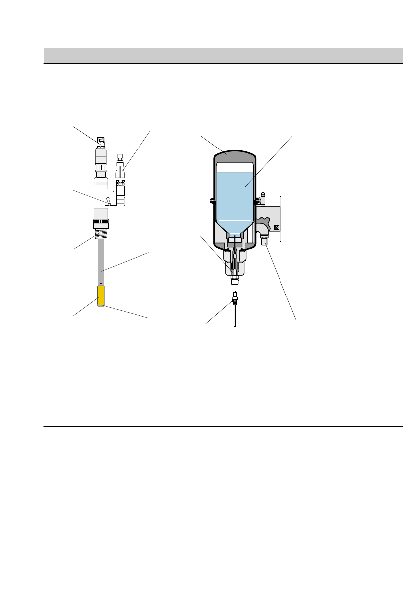
pH-sensitive part Reference system Process connection
• Enamel-lined steel pipe (3)
• Yellow pH-sensitive enamel with metal
reference lead (5)
• Junction (4)
• Memosens plug-in head (1)
• Electrolyte vessel (8)
• Electrolyte bottle with septum (9)
• Electrolyte supply with hose and plug-in
couplings (2 and 11)
• Reference electrode (in sensor head, not
visible from the outside)
Depending on version
• M20 for installation in
existing process
connection
• Nipple DN25
• Nipple DN30
• Varivent DN50/40
• Dairy fitting DN50
• Dairy fitting DN25
• Tri-Clamp DN50
1 Sensor
1 Memosens plug-in head
2 Electrolyte supply
3 Enamel-lined steel pipe
4 Junction
5 pH-sensitive enamel
6 M20 for installation in process
connection
7 Ventilation
Endress+Hauser 7
2 Electrolyte vessel
8 Electrolyte vessel
9 Electrolyte bottle
10 Compressed air connection
11 Electrolyte hose
12 Electrolyte supply coupling
Page 8

Incoming acceptance and product identification Ceramax CPS341D
4 Incoming acceptance and product identification
4.1 Incoming acceptance
1. Verify that the packaging is undamaged.
Notify your supplier of any damage to the packaging.
Keep the damaged packaging until the matter has been settled.
2. Verify that the contents are undamaged.
Notify your supplier of any damage to the delivery contents.
Keep the damaged products until the matter has been settled.
3. Check the delivery for completeness.
Check it against the delivery papers and your order.
4. Pack the product for storage and transportation in such a way that it is protected
against impact and moisture.
The original packaging offers the best protection.
The permitted ambient conditions must be observed (see "Technical data").
If you have any questions, please contact your supplier or your local sales center.
4.2 Product identification
4.2.1 Nameplate
The nameplate provides you with the following information on your device:
• Manufacturer identification
• Order code
• Extended order code
• Serial number
• Safety information and warnings
Compare the data on the nameplate with your order.
‣
4.2.2 Product identification
Product page
www.endress.com/cps341d
Interpreting the order code
The order code and serial number of your product can be found in the following locations:
• On the nameplate
• In the delivery papers
Obtaining information on the product
1. Go to the product page for your product on the Internet.
8 Endress+Hauser
Page 9

Ceramax CPS341D Incoming acceptance and product identification
2. At the bottom of the page, select the "Online Tools" link followed by "Check your device
features".
An additional window opens.
3. Enter the order code from the nameplate into the search field, and then select "Show
details".
You will receive information on each feature (selected option) of the order code.
Manufacturer's address
Endress+Hauser Conducta GmbH+Co. KG
Dieselstraße 24
D-70839 Gerlingen
4.3 Scope of delivery
The delivery comprises:
• Sensor in the version ordered
• Operating Instructions
• Safety instructions for hazardous area
If you have any questions, please contact your supplier or your local sales center.
4.4 Certificates and approvals
4.4.1
Declaration of conformity
The product meets the requirements of the harmonized European standards. As such, it
complies with the legal specifications of the EU directives. The manufacturer confirms
successful testing of the product by affixing to it the mark.
4.4.2 Ex approvals
• ATEX II 1G Ex ia IIC T3/T4/T6 Ga
• IECEx 1G Ex ia IIC T3/T4/T6 Ga
4.4.3 Certification body DEKRA EXAM GmbH
Bochum
Endress+Hauser 9
mark
Hazardous area versions of the digital sensors with Memosens technology are indicated
by a red/orange ring in the plug-in head.
Page 10
Installation Ceramax CPS341D
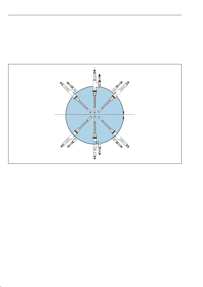
0 ... 360°
5 Installation
5.1 Installation conditions
5.1.1 Orientation
The CPS341D can be installed in any position.
A0013862
3 Angle of installation
10 Endress+Hauser
Page 11

Ceramax CPS341D Installation
295 (11.6)
120 (4.72)
12 (0.47)
112 (4.41)
5.1.2 Dimensions
A0013874
4 Dimensions in mm (inch)
5.2 Mounting the sensor
NOTICE
Internal fittings can damage the sensor enamel
When installing in containers and pipes, keep a sufficient distance from internal fittings
‣
and the wall.
Installing the sensor in the process
1. Version with M20: screw the sensor into an existing process connection.
2. All other versions: mount the sensor on a process connection that is appropriate for the
sensor version.
Endress+Hauser 11
Page 12

Installation Ceramax CPS341D
1 2
3
4
5
6
7
8
9
5.2.1 Installing the electrolyte vessel
5 Electrolyte vessel
1 Clamp 6 Self-locking connector with electrolyte hose
2 Electrolyte bottle 7 Self-locking coupling
3 Mounting plate 8 Cannula
4 Ground terminal 9 Septum
5 Compressed air connection G1/4
NOTICE
Internal pressure in electrolyte system too low
If the internal pressure is too low, there is the danger that the process medium could enter the
sensor through the junction and contaminate the electrolyte.
Set the compressed air supply so that the pressure in the electrolyte vessel is always at
‣
least 0.5 bar (7 psi) above the process pressure.
12 Endress+Hauser
A0014069
Page 13

Ceramax CPS341D Electrical connection
3
Mounting the electrolyte vessel
1. Mount the electrolyte vessel vertically on a wall.
Maximum distance from sensor: 5 m (16 ft) (length of the connecting hose).
2. If necessary, shorten the connecting hose supplied to the desired length.
3. Connect the hose end with the self-locking coupling to the connector of the sensor KCl
coupling.
4. Connect the hose end with the self-locking connector to the coupling of the electrolyte
vessel (→ 5, item 7).
5. Connect the compressed air supply to the G1/4 gland (item 5) via an onsite pressurereducing valve.
6. Set the internal pressure in the electrolyte vessel so that the pressure is at least 0.5 bar
(7 psi) above the process pressure but does not exceed the permitted sensor process
pressure of 6 bar (90 psi.
A higher difference in pressure is possible but increases the level of electrolyte
consumption.
5.2.2 Mounting the optional electrolyte monitor
1. Unscrew the cover of the electrolyte monitor (bubble sensor).
2. Fit the bubble sensor at the outlet of the electrolyte vessel (2) onto the
hose (3).
3. Screw the cover back on.
4. Connect the connector of the connecting cable CPS341Z-D3 to the
M12 coupling (1).
Always order the connecting cable with the bubble sensor. The bubble
sensor cannot work without a cable.
For information on how to connect the external supply voltage:
→ 14
A0014091
6 Electrolyte monitoring
6 Electrical connection
6.1 Connecting the sensor
The electrical connection to the transmitter is performed using the measuring cable CYK10.
Endress+Hauser 13
Page 14

Electrical connection Ceramax CPS341D
GN/YE
YE
GN
BN
WH
GND
+
–
Com A
Com B
GY
CPS341Z-D2
CPS341Z-D4
24 V DC
+
–
BN BU
BK
PNP
max. 200 mA
CPS341Z-D2
+
–
BN BU
BK
PNP
max. 200 mA
+
–
12 ... 30 V DC
A0024019
7 Measuring cable CYK10
NOTICE
Zero point shift as a result of polarization
If the sensor is immersed in the medium and the transmitter is disconnected from the power
supply, polarization can cause an irreversible zero point shift. The device must be recalibrated
in such cases.
Do not disconnect the transmitter from the power supply while the sensor is immersed in
‣
the medium.
When performing maintenance work when the sensor is connected, remove the sensor
‣
from the medium and dry it before you disconnect the transmitter from the power supply.
In general, avoid any kind of conductive connection between the reference and the pH-
‣
sensitive enamel when the device is switched off.
If you have removed the sensor from the medium, it is essential you use the KCl protection
‣
cap specially designed for CPS341D to protect the junction.
6.2 Connecting the optional electrolyte monitor
8 Connection to the customer power supply
with a relay
1. Connect the connecting cable to an onsite power supply provided onsite by the
customer (→ 8, → 9).
14 Endress+Hauser
9 Connection to the customer power supply
with a PLC
Page 15

Ceramax CPS341D Commissioning
2. Connect the M12 connector to the M12 coupling of the bubble sensor (if you have not
already done so during installation).
Light emitting diodes in the cable connector indicate the status in the electrolyte supply
system: green = supply voltage on, green + yellow = air bubble in the hose (electrolyte
vessel empty)
7 Commissioning
Before first commissioning, check if:
• the sensor is correctly installed
• the electrical connection is correct.
Sensor commissioning is a multi-step process:
1. Disinfection of the electrolyte system (optional, for sterile applications)
2. Regeneration of the sensor
3. Filling the electrolyte vessel
4. Calibration/adjustment of the sensor
7.1 Disinfecting the electrolyte system
For sterile applications, you can disinfect the entire electrolyte system with 70% ethanol prior
to actual commissioning (ethanol is not included in the delivery).
The sensor parts in contact with the medium must be sterilized by appropriate means
(SIP).
Endress+Hauser 15
Page 16

Commissioning Ceramax CPS341D
1 2
3
Inserting the ethanol bottle
1.
10
Release the clamp (1) on the mounted electrolyte vessel and remove the top part (2).
2. Fill an empty septum bottle () with 70% ethanol.
3. Place the bottle into the bottom part of the electrolyte vessel with the septum in a
central position and pointing downwards. This causes the cannula of the electrolyte
vessel to pierce the septum.
4. Fit the top part and seal the device tightly with the clamp.
5. If you have not already done so, connect the electrolyte vessel and the sensor via the
electrolyte hose that can be plugged in at both ends.
Disinfecting the electrolyte system
1. Apply a pressure of at least 3 bar (45 psi) to the electrolyte vessel.
16 Endress+Hauser
Page 17

Ceramax CPS341D Commissioning
4
5
2.
11
Open the vent screw on the sensor (5) (one revolution) until approx. 50 to 100 ml of
ethanol flows out of the vent opening (4).
3. Allow the ethanol to act for 2 to 5 minutes.
Removing the ethanol bottle
1. Switch off the compressed air and release the pressure on the electrolyte vessel (release
the thread adapter nut on the plastic insert (→ 10, item 3) by 2-3 revolutions).
2. Once the vessel is unpressurized tighten the thread adapter nut immediately.
3. Release the clamp on the electrolyte vessel and remove the top part.
4. Remove the ethanol bottle.
5. Fill the sensor with electrolyte (→ 18) directly after the disinfection process.
7.2 Regenerating the sensor
Slightly larger measured errors can occur during commissioning when using new sensors and
sensors that been dry for extended periods. Regeneration eliminates these errors. During the
regeneration process, the necessary gel layer forms on the surface of the pH-sensitive enamel.
If the sensor is cleaned and sterilized in the container or pipe before commissioning,
additional regeneration is no longer required.
Regeneration is performed with the sensor installed and connected. The transmitter must be
switched on.
Choose one of the following three ways to regenerate the sensor:
1. Wet the sensor for 12-24 hours.
2. Immerse the sensor in hot water. (70 to 100 °C (160 to 210 °F) for approximately 30
minutes.
Endress+Hauser 17
Page 18

Commissioning Ceramax CPS341D
1 2
3
3. Steam-treat the sensor for 10 to 15 minutes.
7.3 Filling the electrolyte vessel
The electrolyte must be free from bubbles over the entire fill section. This is the only way to
ensure a correct electrical connection between the reference electrode and the junction.
The electrolyte is 3M KCl (pH 4) with an added inhibitor (1 ml/l colloidal silica) that
prevents germ formation.
Inserting the electrolyte bottle
1.
12
Release the clamp (1) on the mounted electrolyte vessel and remove the top part (2).
2. Remove the red sealing cap on the electrolyte bottle.
3. Place the bottle into the bottom part of the electrolyte vessel with the septum in a
central position and pointing downwards.
This causes the cannula of the electrolyte vessel to pierce the septum.
4. Fit the top part and seal the device tightly with the clamp.
Filling the electrolyte system
1. Apply a pressure of at least 3 bar (45 psi) to the electrolyte vessel.
2. If you have not already done so,
connect the electrolyte vessel and the sensor via the electrolyte hose that can be plugged
in at both ends, connect the sensor to the transmitter and switch on the transmitter.
18 Endress+Hauser
Page 19

Ceramax CPS341D Commissioning
4
5
3.
13
Open the vent screw on the sensor (5) (one revolution) until bubble-free electrolyte
exits the vent opening (4).
If you disinfected the electrolyte system beforehand, allow at least 50-100 ml of
electrolyte to escape.
4. Close the vent screw and clean the sensor around the vent opening with water.
5. Establish the process pressure in the electrolyte vessel.
7.4 Calibrating/adjusting the sensor
7.4.1 Need for calibration
The calibration data are stored in the Memosens head at the factory and are transferred to
the transmitter. The sensor is ready for operation immediately.
If the device has not been in operation for an extended period, it is recommended to verify the
calibration data and recalibrate where necessary .
NOTICE
When uninstalled: no electrical contact between the process connection of the sensor
and the calibration buffer
This can cause variations in the measured value
Immerse the sensor into the calibration buffer as far as the sensor's process connection, or
‣
Establish an electrical contact between the process connection and calibration buffer, e.g.
‣
using a wire.
Endress+Hauser 19
Page 20

Diagnostics and troubleshooting Ceramax CPS341D
7.4.2 Types of calibration
The following types of calibration are possible:
• Two-point calibration
With calibration buffers
• Single-point calibration
– Entry of an offset or a reference value
– Sample calibration with laboratory comparative value
• Data entry
Entry of the zero point, slope and temperature
• Temperature adjustment by entering a reference value
7.4.3 Calibration
Follow the instructions in the Operating Instructions of the transmitter.
‣
8 Diagnostics and troubleshooting
Problem Cause Solution
Reading fluctuates when the
electrolyte hose is touched
Reading does not change in
media with different pH
values
Measured value fluctuates
when sensor is not installed
Zero point drifts, is no longer
in permitted range, shifts
during venting
Slope too low or very slow
reaction
• Not vented sufficiently
• Insufficient pressure
Hole in pH enamel/
insulation error
No electrical contact
between the process
connection of the sensor
and the medium
Reference electrode
defective
Limescale or other buildup 1. Measure potential at pH 3 and pH 7
1. Vent
2. Check and increase pressure
Have repaired by the Service Department
1. Immerse the sensor in the medium as far as the
sensor process connection
2. Establish an electrical contact with the process
connection, e.g. using a wire
Have repaired by the Service Department
2. Check slope: → min. 55 mV/pH at 25 °C
3. Immerse sensor for 30 min. in 10% HCl, then wet
with water and measure again
4. If acid treatment does not have the desired effect,
have the sensor inspected by the Service
Department
20 Endress+Hauser
Page 21

Ceramax CPS341D Maintenance
1 2
3
4
9 Maintenance
9.1 Changing the electrolyte bottle
You should change the bottle before it is completely empty. This way you ensure that the
electrolyte system is always full.
If you are using the optional electrolyte monitor, a message is activated when the first air
bubble is detected at the outlet of the vessel. Then replace the bottle of electrolyte within
the next 10 hours.
NOTICE
Process pressure and process temperature
The penetration of medium can contaminate the sensor reference system
Only replace the bottle of electrolyte when no process pressure is applied and at
‣
temperatures below 80 °C (176 °F).
If this is not possible, you must replace the bottle very quickly.
‣
Releasing the pressure on the electrolyte vessel
1.
14
Disconnect the electrolyte hose from the outlet of the electrolyte vessel by pressing the
unlocking unit on the coupling (4) and removing the hose with the connector.
The pressure is maintained briefly in the hose and in the sensor in this way.
2. Switch off the compressed air and release the pressure on the electrolyte vessel (release
the thread adapter nut (item 3) on the plastic insert by 2-3 revolutions).
Endress+Hauser 21
Page 22

Maintenance Ceramax CPS341D
1 2
3
Inserting the electrolyte bottle
1.
15
Release the clamp (1) on the mounted electrolyte vessel and remove the top part (2).
2. Remove the red sealing cap on the electrolyte bottle.
3. Place the bottle into the bottom part of the electrolyte vessel with the septum in a
central position and pointing downwards.
This causes the cannula of the electrolyte vessel to pierce the septum.
4. Fit the top part and seal the device tightly with the clamp.
Filling the electrolyte system
1. Reinsert the (self-locking) connector of the electrolyte hose into the coupling on the
electrolyte vessel.
2. Apply a pressure of at least 3 bar (45 psi) to the electrolyte vessel.
22 Endress+Hauser
Page 23

Ceramax CPS341D Maintenance
4
5
3.
16
Open the vent screw on the sensor (5) (one revolution) until bubble-free electrolyte
exits the vent opening (4).
4. Close the vent screw and clean the sensor around the vent opening with water.
5. Establish the process pressure in the electrolyte vessel.
9.2 Clean sensor
9.2.1 Cleaning agent Suitable cleaning agents
• Water or solvents
• Non-scratch stainless steel cleaner
• Diluted hydrochloric acid (5 to 20%)
NOTICE
Fluorinated acids and abrasive cleaners
Fluorinated acids (e.g. hydrofluoric acid) and abrasive substances corrode the enamel.
Never use fluorinated acids to clean the sensor.
‣
Do not use metal or abrasive cleaning agents.
‣
9.2.2 Clean sensor
NOTICE
Acids and alkalis
Increased enamel corrosion if permitted process limits are exceeded
Avoid exceeding the maximum permitted temperatures and cleaning times.
‣
Please note that when cleaning with alkalis, the level of corrosion doubles with every 10 ˚C
‣
increase in temperature.
Do not concentrations that are higher than the permitted alkali or acid concentrations.
‣
Endress+Hauser 23
Page 24

Maintenance Ceramax CPS341D
1
2 3
4
pH
0
0,1
0,2
0,3
0,4
0,5
t [min]
10 20 30 40 50 60 70
The sensor can be cleaned in place (CIP).
Example:
– (1) 2% alkali, 85 ° C (176 °F), 1 hour
– (2) 1.5% acid, 60 °C (140 °F), 15 minutes
– (3) steam, 135 °C (275 °F)
Cleaning with alkaline media affects the gel layer of the enamel. This results in a zero point
shift which, in turn, causes temporary measured errors.
Regenerating the sensor through subsequent steam treatment, for example, regenerates the
gel layer and corrects the zero point shift.
17 Regeneration after 30-minute CIP with 2% NaOH at 85 °C (185 °F)
1 Regeneration with steam, 135 °C (275 °F
2 Regeneration with water, 95 °C (203 °F)
3 Regeneration with water, 80 °C (176 °F)
4 Regeneration with water, 25 °C (77 °F)
9.2.3 Sterilizing the sensor
The sensor can be sterilized in place (SIP). The following are permitted for SIP:
• Process fluid
• Water vapor
• Alcohol solutions
• Aseptic solutions
24 Endress+Hauser
A0014075
Page 25

Ceramax CPS341D Repairs
10 Repairs
10.1 Spare parts
Description Order number
Kit CPS341D O-ring set for DN25 71118068
Kit CPS341D O-ring set for DN30 71118070
Kit CPS341D O-ring set for various models 71118071
Kit CPS341D clamp seal DIN DN100 71118072
Kit CPS341D insert, pressure vessel complete 71118073
Kit CPS341D cannula holder complete 71118074
Kit CPS341D electrolyte vessel connection 71118075
10.2 Return
The product must be returned if repairs or a factory calibration are required, or if the wrong
product was ordered or delivered. As an ISO-certified company and also due to legal
regulations, Endress+Hauser is obliged to follow certain procedures when handling any
returned products that have been in contact with medium.
To ensure swift, safe and professional device returns, please read the return procedures and
conditions at www.endress.com/support/return-material.
10.3 Disposal
The device contains electronic components and must therefore be disposed of in accordance
with regulations on the disposal of electronic waste.
Observe the local regulations.
11 Accessories
11.1 CPS341Z
The correct operation of the Ceramax CPS341D depends on the reliable supply of KCl to
the reference part of the sensor. The pressurized electrolyte vessel CPS341Z-D1 is
perfectly suitable for this.
The electrolyte supply can be monitored by the ultrasonic level monitoring sensor CPS341ZD2 (air bubble sensor). The ultrasonic sensor requires a supply voltage of 18 to 30 V DC at a
Endress+Hauser 25
Page 26

Accessories Ceramax CPS341D
maximum of 70 mA (without switching current). The signal is output via the relay CPS341ZD4 and is also indicated visually via the LED display CPS341Z-D3.
CPS341Z- Accessories for Ceramax CPS341D
A1 Welding socket DN30, straight
A2 Dummy plug for welding socket DN30
A3 Welding socket DN25, straight
A4 Welding socket DN25, beveled
D1 Electrolyte vessel, stainless steel
D2 Ultrasonic sensor level monitoring
D3D4 Cable with LED indicator
D4 Relay, type KCD2-R, P+F
D5 KCl electrolyte, sterile, 1 l plastic bottle
D6 Demineralized water, sterile, 1 l plastic bottle
D7 Plastic bottle, empty
D8 Protection cap
To obtain a valid order code, simply attach the optional features to the order code. If you have
any questions, please contact our sales office.
11.2 Buffer solutions
High-quality buffer solutions from Endress+Hauser - CPY20
The secondary buffer solutions have been referenced to primary reference material of the PTB
(German Federal Physico-technical Institute) or to standard reference material of NIST
(National Institute of Standards and Technology) according to DIN 19266 by a laboratory
accredited by the DAkkS (German accreditation body) according to DIN 17025.
Product Configurator on the product page: www.endress.com/cpy20
11.3 Cable
CYK10 Memosens data cable
• For digital sensors with Memosens technology
• Product Configurator on the product page: www.endress.com/cyk10
Technical Information TI00118C
26 Endress+Hauser
Page 27

Ceramax CPS341D Technical data
12 Technical data
12.1 Input
12.1.1 Measured values
pH value
Temperature
12.1.2 Measuring range
0 to 10 pH (linear range)
-2 to 14 pH (application)
0 to 140 °C (32 to 280 °F)
12.2 Environment
12.2.1 Ambient temperature range
The sensor may not be used if the temperature drops below 0 °C (32 °F).
12.2.2 Storage temperature
0 to 50 °C (32 to 122 °F)
12.2.3 Degree of protection
IP 68 (10 m (33 ft) head of water at 25 ˚C (77 ˚F) over 45 days, 1 mol/l KCl)
12.3 Process
12.3.1 Process temperature
0 to 140 °C (32 to 280 °F)
12.3.2 Process pressure
1 to 7 bar (14 to 87 psi), absolute
12.3.3 Minimum conductivity
Min. 50 μS/cm
12.3.4 pH range
-2 to 14 pH
12.4 Mechanical construction
12.4.1 Weight
0.6 kg (1.3 lbs)
Endress+Hauser 27
Page 28

Technical data Ceramax CPS341D
12.4.2 Materials
Sensor body: Glass-lined steel, chemically resistant and shock
resistant
Adapter and terminal head: Stainless steel 1.4404 (AISI 316 L), PVDF, PTFE
Electrolyte vessel: Stainless steel 1.4301 (AISI 304)
Process connections: Stainless steel 1.4404 (AISI 316 L)
12.4.3 Process connections
Depending on version
• M20 (replacement for installed sensor)
• Nipple DN25
• Nipple DN30
• Varivent DN50/40
• Dairy fitting DN50
• Dairy fitting DN25
• Tri-Clamp DN50
12.4.4 Temperature sensor
NTC 30KΩ
12.4.5 Reference system
Ag/AgCl with 3 M KCl and inhibitor (1 ml/l colloidal silica)
28 Endress+Hauser
Page 29

Index
A
Accessories ..................... 25
Ambient temperature range ........... 27
Index
Measuring range ..................27
Mechanical construction ............. 27
Minimum conductivity .............. 27
B
Buffer solutions .................. 26
C
Cable .........................26
Calibration
Need ...................... 19
Types ......................20
Certificates and approvals ............. 9
Certification body .................. 9
Cleaning agent ................... 23
Commissioning ...................15
D
Declaration of conformity ..............9
Degree of protection ................27
Designated use ....................5
Diagnostics ..................... 20
Dimensions ..................... 11
Disposal ....................... 25
E
Electrical connection ................13
Electrolyte
Bottle change .................21
Connecting the optional monitor ..... 14
Disinfecting the system ........... 15
Filling the vessel ............... 18
Ex approvals ..................... 9
H
Hazardous areas ................... 6
I
Incoming acceptance ................ 8
Input .........................27
Installation conditions ...............10
M
Maintenance .................... 21
Manufacturer's address ............... 9
Materials ...................... 28
Measured values .................. 27
N
Nameplate ...................... 8
O
Occupational safety ................. 5
Operational safety ..................5
Orientation ..................... 10
P
pH range .......................27
Process connections ................ 28
Process pressure .................. 27
Process temperature ................27
Product description ................. 6
Product identification ................ 8
Product page ..................... 8
Product safety .................... 6
R
Reference system ..................28
Repairs ........................25
Return ........................ 25
S
Safety
Electrical equipment in hazardous areas .. 6
Occupational safety .............. 5
Operation ....................5
Product ..................... 6
Safety instructions ..................5
Scope of delivery ...................9
Sensor
Calibration .................. 20
Cleaning ....................23
Connecting .................. 13
Description ................... 6
Regeneration ................. 17
Sterilization ..................24
Spare parts ..................... 25
State of the art .................... 6
Storage temperature ................27
Symbols ........................ 4
Endress+Hauser 29
Page 30

Index
T
Technical data ................... 27
Temperature sensor ................ 28
Troubleshooting .................. 20
U
Use ...........................5
W
Warnings ....................... 4
Weight ........................27
30 Endress+Hauser
Page 31

Page 32

*71332820*
71332820
www.addresses.endress.com
 Loading...