

Page 1
BA01279C/07/EN/03.16
71324469
Products Solutions Services
Operating Instructions
Cleanfit CPA875
Retractable process assembly for sterile and hygienic
applications
Page 2

Page 3

Table of contents
Table of contents
1 Document information .............. 4
1.1 Warnings ............................ 4
1.2 Symbols used .......................... 4
1.3 Symbols on the device ................... 4
2 Basic safety instructions ............ 5
2.1 Requirements for the personnel ............ 5
2.2 Designated use ........................ 5
2.3 Occupational safety ..................... 5
2.4 Operational safety ...................... 6
2.5 Product safety ......................... 6
3 Incoming acceptance and product
identification ....................... 7
3.1 Incoming acceptance .................... 7
3.2 Scope of delivery ....................... 7
3.3 Product identification .................... 8
3.4 Certificates and approvals ................ 9
4 Installation ....................... 10
4.1 Installation conditions .................. 10
4.2 Installation .......................... 16
4.3 Installing the sensor ................... 23
4.4 Post-installation check .................. 27
Index .................................. 53
5 Operation options ................. 28
5.1 Commissioning ....................... 28
5.2 Operating elements .................... 29
5.3 Manual operation ..................... 30
5.4 Pneumatic operation ................... 30
6 Maintenance ...................... 32
6.1 Maintenance intervals .................. 32
6.2 Cleaning the assembly .................. 33
6.3 Cleaning the sensor .................... 33
6.4 Cleaning agent ....................... 34
6.5 Replacing seals ....................... 35
7 Repairs ........................... 44
7.1 Spare parts .......................... 44
7.2 Return .............................. 44
7.3 Disposal ............................ 44
8 Accessories ....................... 45
8.1 Installation material for rinse connections ... 46
8.2 Sensors ............................. 47
9 Technical data .................... 50
Endress+Hauser 3
Page 4
Document information Cleanfit CPA875
1 Document information
1.1 Warnings
Structure of information Meaning
DANGER
L
Causes (/consequences)
Consequences of non-compliance
(if applicable)
Corrective action
‣
WARNING
L
Causes (/consequences)
Consequences of non-compliance
(if applicable)
Corrective action
‣
CAUTION
L
Causes (/consequences)
Consequences of non-compliance
(if applicable)
Corrective action
‣
NOTICE
Cause/situation
Consequences of non-compliance
(if applicable)
Action/note
‣
This symbol alerts you to a dangerous situation.
Failure to avoid the dangerous situation will result in a fatal or serious
injury.
This symbol alerts you to a dangerous situation.
Failure to avoid the dangerous situation can result in a fatal or serious
injury.
This symbol alerts you to a dangerous situation.
Failure to avoid this situation can result in minor or more serious injuries.
This symbol alerts you to situations which may result in damage to
property.
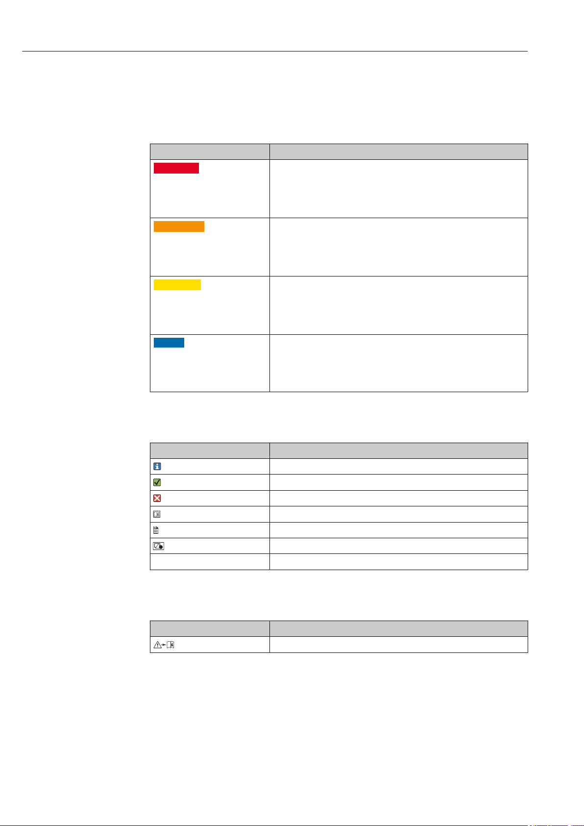
1.2 Symbols used
Symbol Meaning
Additional information, tips
Permitted or recommended
Not permitted or not recommended
Reference to device documentation
Reference to page
Reference to graphic
Result of a step
1.3 Symbols on the device
Symbol Meaning
Reference to device documentation
4 Endress+Hauser
Page 5

Cleanfit CPA875 Basic safety instructions
2 Basic safety instructions
2.1 Requirements for the personnel
• Installation, commissioning, operation and maintenance of the measuring system may
be carried out only by specially trained technical personnel.
• The technical personnel must be authorized by the plant operator to carry out the
specified activities.
• The electrical connection may be performed only by an electrical technician.
• The technical personnel must have read and understood these Operating Instructions
and must follow the instructions contained therein.
• Measuring point faults may be repaired only by authorized and specially trained
personnel.
Repairs not described in the Operating Instructions provided may only be carried out
directly by the manufacturer or by the service organization.
2.2 Designated use
The Cleanfit CPA875 retractable assembly, which can be manually or pneumatically
operated, is designed for the installation of sensors in vessels and pipes.
Thanks to its design, it can be used in pressurized systems (see "Technical data").
Use of the device for any purpose other than that described, poses a threat to the safety of
people and of the entire measuring system and is therefore not permitted.
The manufacturer is not liable for damage caused by improper or non-designated use.
2.3 Occupational safety
As the user, you are responsible for complying with the following safety conditions:
• Installation guidelines
• Local standards and regulations
• Regulations for explosion protection
Endress+Hauser 5
Page 6

Basic safety instructions Cleanfit CPA875
2.4 Operational safety
1. Before commissioning the entire measuring point, verify that all connections are
correct. Ensure that electrical cables and hose connections are undamaged.
2. Do not operate damaged products, and safeguard them to ensure that they are not
operated inadvertently. Label the damaged product as defective.
3. If faults cannot be rectified:
Take the products out of operation and safeguard them to ensure that they are not
operated inadvertently.
2.5 Product safety
2.5.1 State of the art
The product is designed to meet state-of-the-art safety requirements, has been tested, and
left the factory in a condition in which it is safe to operate. The relevant regulations and
European standards have been observed.
6 Endress+Hauser
Page 7

Cleanfit CPA875 Incoming acceptance and product identification
3 Incoming acceptance and product
identification
3.1 Incoming acceptance
1. Verify that the packaging is undamaged.
Notify your supplier of any damage to the packaging.
Keep the damaged packaging until the matter has been settled.
2. Verify that the contents are undamaged.
Notify your supplier of any damage to the delivery contents.
Keep the damaged products until the matter has been settled.
3. Check the delivery for completeness.
Check it against the delivery papers and your order.
4. Pack the product for storage and transportation in such a way that it is protected
against impact and moisture.
The original packaging offers the best protection.
The permitted ambient conditions must be observed (see "Technical data").
If you have any questions, please contact your supplier or your local sales center.
3.2 Scope of delivery
The scope of delivery comprises:
• Assembly in the version ordered
• Operating Instructions
Endress+Hauser 7
Page 8

Incoming acceptance and product identification Cleanfit CPA875
3.3 Product identification
3.3.1 Nameplate
The nameplate provides you with the following information on your device:
• Manufacturer identification
• Order code
• Extended order code
• Serial number
• Ambient and process conditions
• Safety information and warnings
Compare the data on the nameplate with your order.
3.3.2 Product identification
The order code and serial number of your product can be found in the following locations:
• On the nameplate
• In the delivery papers
Obtaining information on the product
1. Go to the product page for your product on the Internet.
2. At the bottom of the page, select the "Online Tools" link followed by "Check your
device features".
An additional window opens.
3. Enter the order code from the nameplate into the search field, and then select "Show
details".
You will receive information on each feature (selected option) of the order code.
8 Endress+Hauser
Page 9

Cleanfit CPA875 Incoming acceptance and product identification
3.4 Certificates and approvals
Pharma CoC
No materials or ingredients derived from animals are used during the entire production of
all the parts in contact with the process.
Biological reactivity (USP Class VI) (optional)
The plastic and elastomer product components that are in contact with the medium have
passed the biological reactivity tests as per USP <87> and <88> Class VI.
EHEDG
The assembly was certified in accordance with the requirements of EHEDG TYP EL Class I
(cleanability). The double-chamber version with sensor cleaning in the "inner" service
chamber is certified in accordance with EHEDG type EL aseptic class I (cleanability and
sterility).
ASME BPE
The Cleanfit CPA875 retractable assembly has been developed following ASME BPE
Standard 2012 and meets the relevant requirements of sections GR, SD, DT, MJ, SF, SG,
PM, MM and PI which are significant for a retractable assembly.
FDA
All materials in contact with the product are listed by the FDA.
Suitable process connections and seals must be used for hygienic designs as per
EHEDG, ASME BPE or 3-A.
RL 94/9/EC (ATEX)
The assembly does not fall within the scope of the directive. However, if conditions for safe
use are adhered to, it may be deployed in the hazardous area.
CE/PED
The CPA875 assembly has been manufactured according to good engineering practice in
accordance with Article 3, Paragraph 3 of the Pressure Equipment Directive 97/23/EC and
therefore is not required to bear the CE label.
EC VO 1935/2004
The assembly meets the requirements for materials that come into contact with food.
Endress+Hauser 9
Page 10

Installation Cleanfit CPA875
4 Installation
4.1 Installation conditions
4.1.1 Orientation
The assembly is designed for installation on tanks and pipes. Suitable process connections
must be available for this.
NOTICE
Frost damage to the assembly
If used outdoors, ensure that water cannot penetrate the drive.
‣
For 3-A-compliant installation, please observe the following:
After the device has been mounted, hygienic integrity must be guaranteed. To do so,
the leakage hole must be located at the lowest point on the device. In addition, 3-Acompliant process connections must be used.
The assembly is designed in such a way that there are no restrictions with regard to the
orientation.
The sensor that is used can restrict the orientation.
The "inner" service chamber and "front" service chamber can drain on their own with an
installation position of between 0° and 15° to the horizontal.
10 Endress+Hauser
Page 11
Cleanfit CPA875 Installation
XM/XS = 443/479 (17.44/18.86)
A
B
XP
XP
168 (6.61)
73
(2.87)
61
(2.40)
117
(4.61)
XA
XM/XS = 443/479 (17.44/18.86)
165 (6.50)
73
(2.87)
40
(1.57)
61
(2.40)
107
(4.21)
XA
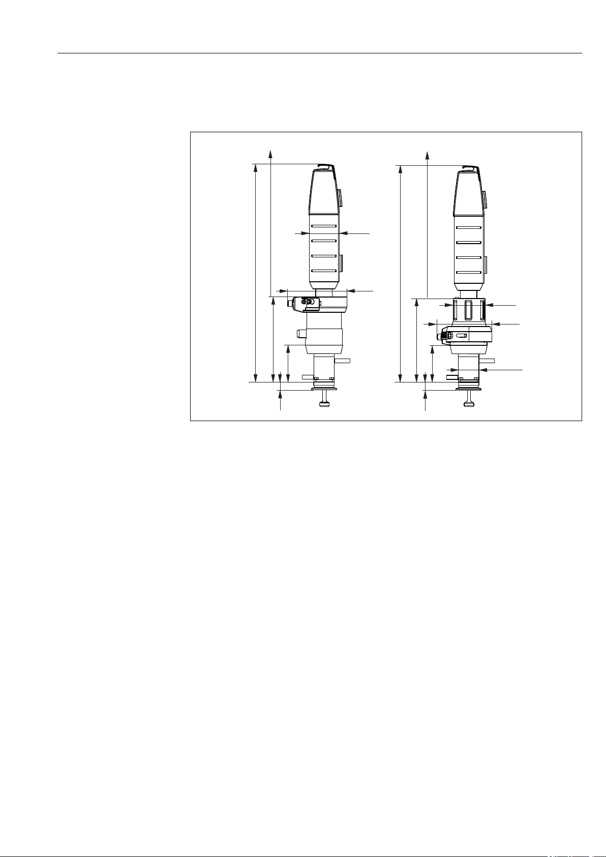
4.1.2 Dimensions
Short version
A0018665
1 Dimensions for short version (36 mm stroke)
A Pneumatic drive
B Manual drive
XM Assembly in measuring position
XS Assembly in service position
XP Height of particular process connection (see table below)
XA Necessary mounting distance for sensor replacement = 425 mm (16.73")
Endress+Hauser 11
Page 12
Installation Cleanfit CPA875
A
B
XM/XS = 558/635 (21.97/25.0)
XM/XS = 524/604 (20.63/23.82)
XP
283 (11.14)
141 (5.55)
61
(2.40)
117
(4.61)
XA
XA
246 (9.69)
107 (4.21)
XP
61
(2.40)
107
(4.21)
40
(1.57)
C
XM/XS = 318/396 (12.52/15.59
XA
246 (9.69)
107 (4.21)
XP
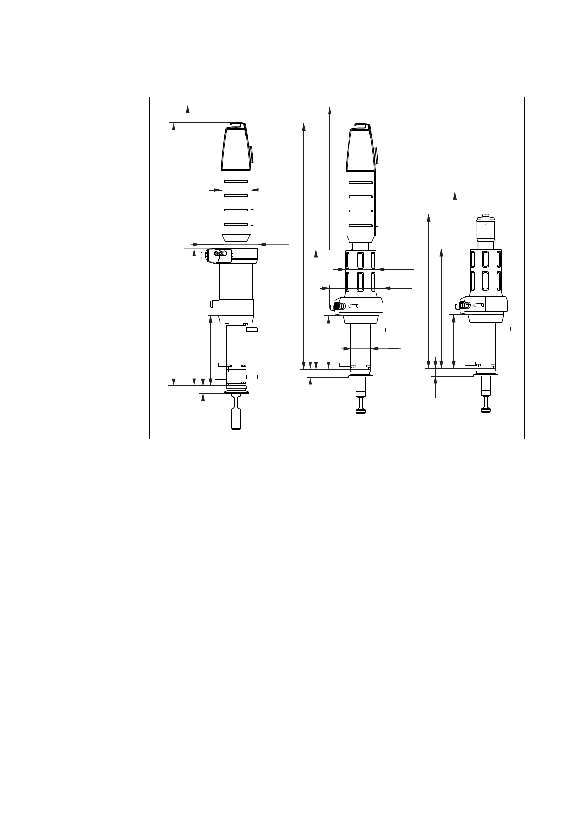
Long version
2 Dimensions for long version (78 mm stroke)
A Pneumatic drive
B Manual drive
C Manual drive with small protection cap
XM Assembly in measuring position
XS Assembly in service position
XP Height of particular process connection (see table below)
XA Necessary mounting distance for sensor replacement
The mounting distance XA is 440 mm (17.32") for 225 mm sensors
The mounting distance XA is 610 mm (24.02") for 360 mm sensors
A0018666
12 Endress+Hauser
Page 13
Cleanfit CPA875 Installation
Process connection height
Process connection Height XP in mm (inch)
CA Clamp ISO 2852, ASME BPE-2012, 1½"
CB Clamp ISO 2852, ASME BPE-2012, 2"
CC Clamp ISO 2852, ASME BPE-2012, 2½"
DA Aseptic DN 25 clampable DIN 11864-3 A
DC Aseptic DN 50 screw-in DIN 11864-1 A
DF Aseptic DN 50 grooved flange DIN 11864-2 A
EA Neumo BioControl D 65
EB Neumo BioConnect D 50
EF Neumo BioConnect D 65
MA Dairy fitting DN 50 DIN 11851
(EHEDG approval only with seal from Siersema)
MB Dairy fitting DN 65 DIN 11851
(EHEDG approval only with seal from Siersema)
VA Varivent flange N (DN 40 to 100)
14.9 (0.59)
A0021866
19.5 (0.77)
A0021867
13.0 (0.51)
A0021869
16.0 (0.63)
A0021871
16.0 (0.63)
A0021872
14.2 (0.56)
A0021874
25.0 (0.98)
A0021875
10.5 (0.41)
A0021877
10.5 (0.41)
A0021876
14.5 (0.57)
A0021879
13.8 (0.54)
A0021878
19.0 (0.75)
A0021873
Endress+Hauser 13
Page 14
Installation Cleanfit CPA875
X1
X2
X1
X2
X2
X1
1 2 / 3 / 6
4 / 5
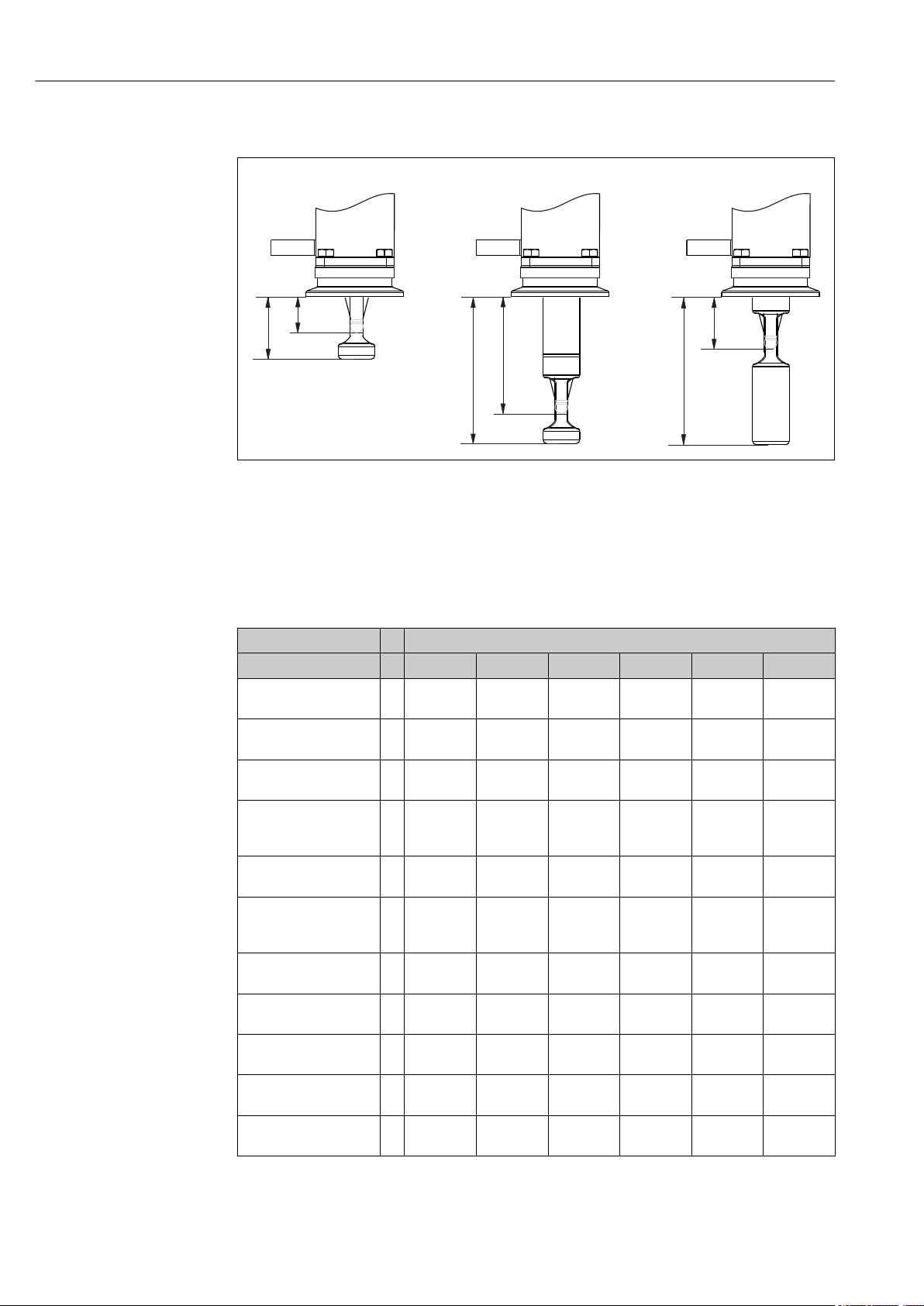
4.1.3 Immersion depths
A0017745
3 Immersion depths for different service chambers
1 Single chamber / 36 mm stroke / sensor 225 mm incl. KCl
2 Single chamber / 78 mm stroke / sensor 225 mm excl. KCI
3 Single chamber / 78 mm stroke / sensor 360 mm incl. KCl
4 Double chamber / 78 mm stroke / sensor 225 mm excl. KCl / service position, "inner" service chamber
5 Double chamber / 78 mm stroke / sensor 360 mm incl. KCl / service position, "inner" service chamber
6 Double chamber / 78 mm stroke / sensor 360 mm incl. KCl / service position, "front" service chamber
Immersion depths in mm (inch)
Process connection 1 2 3 4 5 6
CA Clamp ISO2852
ASME BPE-2012 1½"X1X2
CB Clamp ISO2852
ASME BPE-2012 2"
CC Clamp ISO2852
ASME BPE-2012 2½"X1X2
DA Aseptic DN 25
clampable DIN11864-3
A
DC Aseptic DN 50
screw-in DIN11864-1 AX1X2
DF Aseptic DN 50
Grooved flange
DIN11864-2 A
EA Neumo Biocontrol
D65
EB Neumo Bioconnect
D50
EF Neumo Bioconnect
D65
MA Dairy fitting
DN 50 DIN11851
MB Dairy fitting
DN 65 DIN11851
20.6 (0.81)
31.6 (1.24)
X1X216.1 (0.63)
27.1 (1.07)
22.6 (0.89)
33.6 (1.32)
X1X219.6 (0.77)
30.6 (1.20)
27.1 (1.07)
38.1 (1.50)
X1X221.4 (0.84)
32.4 (1.28)
X1X227.6 (1.09)
38.6 (1.52)
X1X222.6 (0.89)
33.6 (1.32)
X1X220.6 (0.81)
31.6 (1.24)
X1X221.1 (0.83)
32.1 (1.26)
X1X221.8 (0.86)
32.8 (1.29)
62.1 (2.44)
73.1 (2.88)
57.6 (2.27)
68.6 (2.70)
64.1 (2.52)
75.1 (2.96)
61.1 (2.41)
72.1 (2.84)
68.6 (2.70)
79.6 (3.13)
62.9 (2.48)
73.9 (2.91)
69.1 (2.72)
80.1 (3.15)
64.1 (2.52)
75.1 (2.96)
62.1 (2.44)
73.1 (2.88)
62.6 (2.46)
73.6 (2.90)
63.3 (2.49)
74.3 (2.93)
Service chamber
62.1 (2.44)
73.1 (2.88)
57.6 (2.27)
68.6 (2.70)
64.1 (2.52)
75.1 (2.96)
61.1 (2.41)
72.1 (2.84)
68.6 (2.70)
79.6 (3.13)
62.9 (2.48)
73.9 (2.91)
69.1 (2.72)
80.1 (3.15)
64.1 (2.52)
75.1 (2.96)
62.1 (2.44)
73.1 (2.88)
62.6 (2.46)
73.6 (2.90)
63.3 (2.49)
74.3 (2.93)
28.1 (1.11)
73.1 (2.88)
23.6 (0.93)
68.6 (2.70)
30.1 (1.19)
75.1 (2.96)
27.1 (1.07)
72.1 (2.84)
34.6 (1.36)
79.6 (3.13)
28.9 (1.14)
73.9 (2.91)
35.1 (1.38)
80.1 (3.15)
30.1 (1.19)
75.1 (2.96)
28.1 (1.11)
73.1 (2.88)
28.6 (1.13)
73.6 (2.90)
29.3 (1.16)
74.3 (2.93)
28.1 (1.11)
73.1 (2.88)
23.6 (0.93)
68.6 (2.70)
30.1 (1.19)
75.1 (2.96)
27.1 (1.07)
72.1 (2.84)
34.6 (1.36)
79.6 (3.13)
28.9 (1.14)
73.9 (2.91)
35.1 (1.38)
80.1 (3.15)
30.1 (1.19)
75.1 (2.96)
28.1 (1.11)
73.1 (2.88)
28.6 (1.13)
73.6 (2.90)
29.3 (1.16)
74.3 (2.93)
62.1 (2.44)
73.1 (2.88)
57.6 (2.27)
68.6 (2.70)
64.1 (2.52)
75.1 (2.96)
61.1 (2.41)
72.1 (2.84)
68.6 (2.70)
79.6 (3.13)
62.9 (2.48)
73.9 (2.91)
69.1 (2.72)
80.1 (3.15)
64.1 (2.52)
75.1 (2.96)
62.1 (2.44)
73.1 (2.88)
62.6 (2.46)
73.6 (2.90)
63.3 (2.49)
74.3 (2.93)
14 Endress+Hauser
Page 15
Cleanfit CPA875 Installation
81.4 (3.20)
70.4 (2.77)
35 (1.38)
23
(0.91)
A B
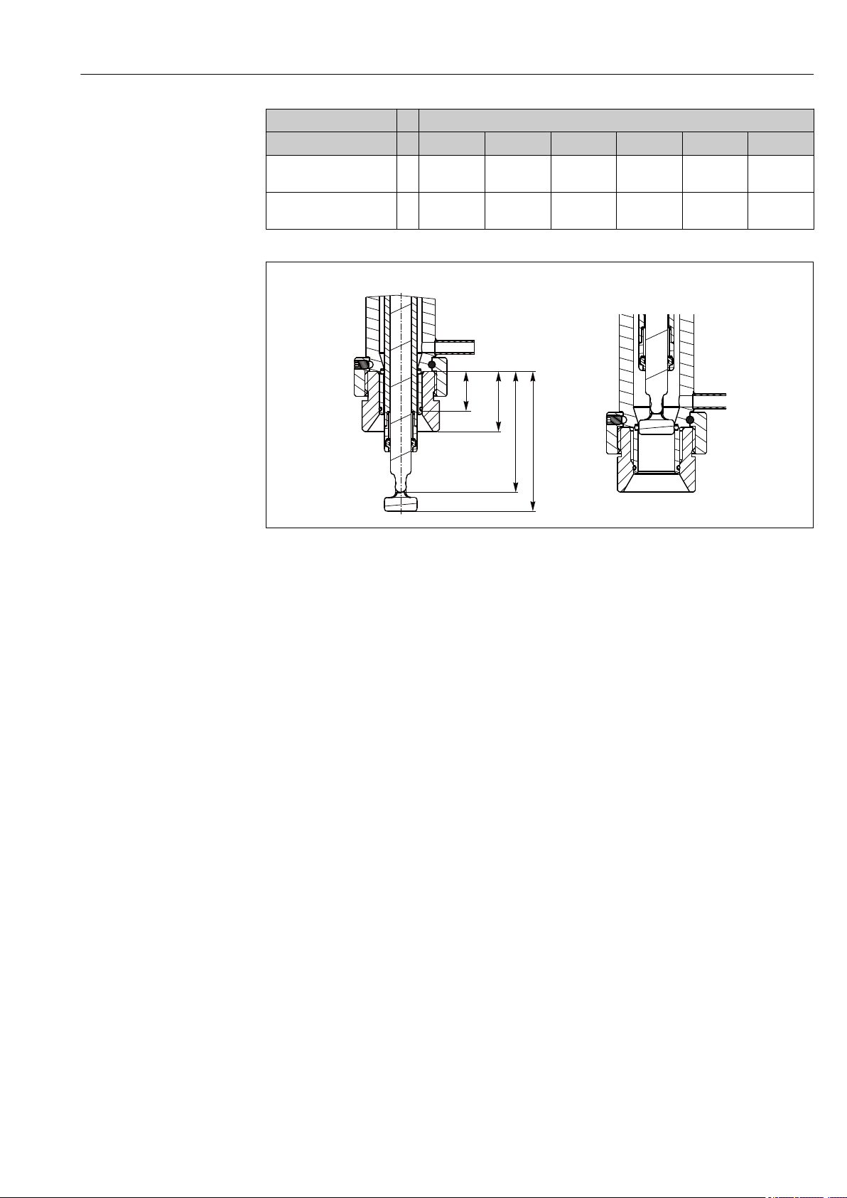
Service chamber
Process connection 1 2 3 4 5 6
NA Thread ISO228
G1¼
VA Varivent flange
N (DN 40 to DN 100)X1X2
X1
X2
16.6 (0.65)
27.6 (1.09)
70.4 (2.77)
81.4 (3.20)
58.1 (2.29)
69.1 (2.72)
70.4 (2.77)
81.4 (3.20)
58.1 (2.29)
69.1 (2.72)
24.1 (0.95)
69.1 (2.72)
24.1 (0.95)
69.1 (2.72)
58.1 (2.29)
69.1 (2.72)
A0022162
4 Immersion depth in mm (inch) for process connection NA thread ISO228 G1¼ (service chamber 2 and 3)
in measurement and service position
Endress+Hauser 15
Page 16
Installation Cleanfit CPA875
2
3
4
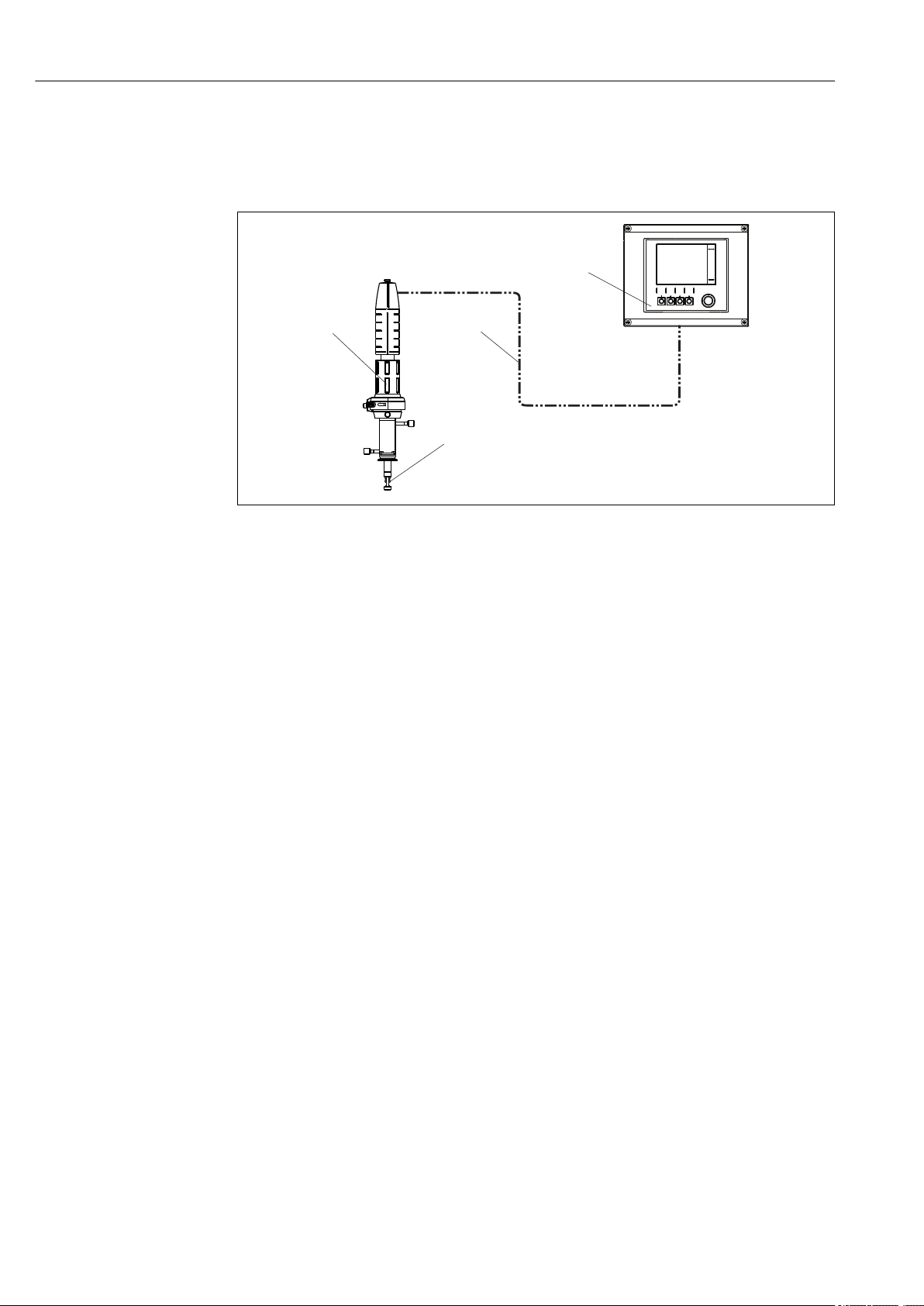
4.2 Installation
4.2.1 Measuring system with single chamber
A0017811
5 Measuring system (example)
1 Cleanfit assembly CPA875
2 Measuring cable
3 Liquiline CM44x transmitter
4 Sensor
16 Endress+Hauser
Page 17
Cleanfit CPA875 Installation
3
4
1 2
3
5
6
6
7
8
11
12
21
22
31 32
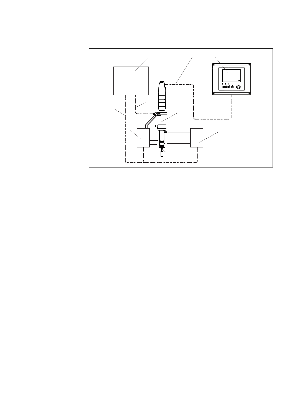
4.2.2 Measuring system with double chamber
A0022821
6 Measuring system with pneumatic drive and double chamber (example)
1 Control unit 7 Limit position switch relay signal
2 Measuring cable 8 Control signals (electric/pneumatic)
3 Liquiline CM44x transmitter 11/12Inlet/outlet of "inner" service chamber
4 Cleanfit assembly CPA875 21/22Inlet/outlet of "front" service chamber
5 Sensor 31/32Drive control
6 Valve block
Endress+Hauser 17
Page 18

Installation Cleanfit CPA875
4.2.3 Installing the assembly in the process
WARNING
L
Risk of injury from high pressure, high temperature or chemical hazards if process
medium escapes.
Wear protective gloves, protective goggles and protective clothing.
‣
Only mount the assembly if the containers or pipes are empty and unpressurized.
‣
Prior to installation, check the flange seal between the flanges.
1. Move the assembly to the service position (the triangle position marking is visible
(→ 7).
2. Secure the assembly to the tank or piping using the process connection.
3. Follow the instructions in the next section to connect pipes for compressed air and
rinse water (for the relevant assembly version).
7 Position markings (service position)
A0023307
18 Endress+Hauser
Page 19

Cleanfit CPA875 Installation
1
2
3
4
5
6
7
8
9
4.2.4 Pneumatic connection for automatic operation
Prerequisites:
• Air pressure 4 to 7 bar (58 to 102 psi)
• Compressed air quality in accordance with ISO 8573-1:2001
Quality class 3.3.3 or 3.4.3
• Solids class 3 (max. 5 μm, max. 5 mg/m3, contamination with particles)
• Water content for temperatures ≥ 15 °C: class 4 pressure condensation point 3 °C or
lower
• Water content for temperatures of 5 to 15 °C: class 3 pressure condensation point -20 °C
or lower
• Oil content class 3 (max. 1 mg/m3)
• Air temperature: 5 °C or higher
• No continuous air consumption
• Minimum nominal diameter of air pipes: 2 mm (0.08 ")
Connection: Push-in fitting M5, hose 4/2 mm OD/ID (adapter for 6/4 mm OD/ID
enclosed)
Damage to seals due to excessive air pressure!
If the air pressure can increase to more than 7 bar (102 psi) (even short pressure surges),
a pressure-reducing valve must be installed upstream.
1 Rinse connection
2 Automatic limit position lock, process
3 Connection for limit position switch
4 Automatic limit position lock, service
5 Sensor head
6 Fastening ring for protection cap
7 Pneumatic connection (move to
measuring position)
8 Pneumatic connection (move to service
position)
9 Rinse connection
A0029435
8 Assembly with pneumatic drive (without
protection cap)
Use a pneumatic change-over valve (4/2-way valve) to move the assembly. Connect
both inputs. If you connect only one input (e.g. for test purposes), the piston will be
blocked, as the sensor guide moves before the limit position lock is deactivated.
Endress+Hauser 19
Page 20

Installation Cleanfit CPA875
3
3
4
5
A B
C
1
2
1
2
1
2
4.2.5 Rinse connections
The service chamber connections of the sterile CPA875 retractable assembly make it
possible to clean the chamber and the sensor with water or a cleaning solution at a
pressure of 6 bar (87 psi) max. or to sterilize it with steam (SIP).
The retractable assembly can be selected with a single- or double-chamber system. If the
double-chamber system is used, all four connections must be connected to inlet and outlet
pipes.
Seals can be damaged if the water pressure is too high.
Install an pressure-reducing valve upstream if there is a possibility that the water
pressure will increase to more than 6 bar (87 psi) (including any short pressure
surges).
4.2.6 Assignment of rinse connections for double chamber
A0023348
9 Changing the chamber volume
3 "Moving" seals in the double chamber
4 Chamber volume in service position
5 Chamber volume in measuring position
10 Assignment of rinse inlet and outlet
A "Cleaning" state
B "Move from service position to measuring position" state
C "Move from measuring position to service position" state
1 Service chamber inlet
2 Service chamber outlet
A0022805
20 Endress+Hauser
Page 21

Cleanfit CPA875 Installation
BN
BN
BU
BU
L+
L+
L-
L-
A
B
C D
E
In the "Cleaning" state (A), the inlet and outlet of the "inner" service chamber are used as
follows (the internal volume of the "front" service chamber does not change, and so no
pressure compensation measures are required here):
• Depending on the cleaning method, cleaning agent and purge gas are supplied via the
inlet (1).
• These media are removed via the outlet (2).
In the "Move from service position to measuring position" state (B), the pressure conditions
in the service chamber must be balanced when moving. The inlet and outlet of the service
chamber are assigned as follows:
• The air is removed via the inlet (1) (inlet is open).
• The air is supplied via the outlet (2).
In the "Move from measuring position to service position" state (C), the pressure conditions
in the service chamber must be balanced when moving. The inlet and outlet of the service
chamber are assigned as follows:
• The air is supplied via the inlet (1).
• The air is removed via the outlet (2) (outlet is open).
The drive must be controlled simultaneously with the control of the inlets and outlets
of the "inner service chamber".
The controller for the inlets, outlets and the drive is installed at the place of
installation. It is not included in the delivery for the assembly.
4.2.7 Connecting the limit position switches
With limit position detection, you can notify a system located downstream (transmitter,
switching amplifier, output interface terminal) whether the assembly is in the
measurement or service position(in the case of a manual drive, only the measurement
position is queried).
The assembly can be ordered directly with limit position detection, or it can be retrofitted
at a later stage.
Switching element function: NAMUR NC contact (inductive)
Switching distance: 1.5 mm (0.06 ")
Nominal voltage: 8 V
Switching frequency: 0 to 5000 Hz
Housing material: Stainless steel
A0017831
Endress+Hauser 21
11 Inductive limit position switches
A Limit position switch, service position
B Limit position switch, measuring position
C Connector, M12, solder side (inside of assembly)
D Coding
E Connector, Pin side (outside of assembly)
Page 22

Installation Cleanfit CPA875
BN
BK
BU
WH
1
2
3
4
+
+
-
-
A0022163
12 Connecting cable for limit position switch on transmitter, switching amplifier, output interface terminal
etc.
1 "Measuring" position
2 "Measuring" position
3 "Service" position
4 "Service" position
Only pins 1 and 2 are assigned for manually activated assemblies with one switch
(measuring position).
Signal table for limit position switches
Position of assembly Limit position switch for "measuring"
position
Measurement Active LOW (≥ 3 mA) Active LOW (≥ 3 mA)
Service Active HIGH (≤ 1 mA) Active HIGH (≤ 1 mA)
Limit position switch for "service"
position
22 Endress+Hauser
Page 23

Cleanfit CPA875 Installation
1
1
2
A B
1
2
4.3 Installing the sensor
4.3.1 Preparing the sensor and assembly
A0030154
13 Installing the sensor
1 Thrust collar with O-ring
1. Remove the protection cap from the sensor. Ensure that the O-ring and thrust collar
(→ 13, item 1) are present.
2. Immerse the sensor shaft in water. This makes for easier installation.
3. Move the assembly to the service position.
4.3.2 Installing and removing sensors
A0030155
14 Sensor installation options
1 Sensor adapter
2 Retraction pipe
A Sensor adapter is on top of the retraction pipe
B Sensor adapter is below the retraction pipe (not visible)
Depending on the assembly version, the sensor adapter is either visible (→ 14, A) or
installed inside the retraction pipe where it is not visible (B). As a result, the procedures
for installing and removing the sensors differ as follows:
Endress+Hauser 23
Page 24

Installation Cleanfit CPA875
1
2
3
4
Installing and removing sensors if the sensor adapter is visible (pos. A)
A0030186
15 Installing the sensor
1 Open-ended wrench (AF 17/19 mm)
2 Protection cover
3 Dummy plug
4 Sensor
Gel and KCl sensors can be installed in this version.
Install the sensor as follows:
1. Remove the protection cap (→ 15, item 2) (this is possible only if the assembly is
in the service position).
2. Remove the yellow dummy plug (pos. 3).
3. Using the open-ended wrench (item 1), screw in the sensor (item 4) in the place of
the dummy plug and hand-tighten (3 Nm (2.2 lbf ft)).
4. Attach the open-ended wrench back into the protection cap.
5. Put the protection cap on the assembly. When doing so, guide the measuring cable
through the cable run (top of protection cap).
Always install the protection cap before moving the assembly to the measuring
position. The protection cap cannot be removed in the measuring position. This
prevents the sensor from being removed.
24 Endress+Hauser
Page 25

Cleanfit CPA875 Installation
3
4
5
1
2
Installing and removing sensors if the sensor adapter is not visible (pos. B)
A0030187
16 Installing the sensor
1 Socket wrench (AF 17/19 mm)
2 Protection cover
3 Dummy plug (protection cap)
4 Sensor
5 Retraction pipe
Gel sensors can be installed in this version. To install KCl sensors, you will need a "Gel
- KCl adapter".
Install the sensor as follows:
1. Remove the protection cap (→ 16, item 2) (this is possible only if the assembly is
in the service position).
2. Unscrew and remove the retraction pipe (pos. 5) (in an anticlockwise direction).
3. Remove the yellow dummy plug (pos. 3).
4. Using the open-ended wrench (item 1), screw in the sensor (item 4) in the place of
the dummy plug and hand-tighten (3 Nm (2.2 lbf ft)).
5. Screw the retraction pipe back in.
6. Attach the open-ended wrench back into the protection cap.
7. Put the protection cap on the assembly. When doing so, guide the measuring cable
through the cable run (top of protection cap).
Always install the protection cap before moving the assembly to the measuring
position. The protection cap cannot be removed in the measuring position. This
prevents the sensor from being removed.
Endress+Hauser 25
Page 26

Installation Cleanfit CPA875
1
2
3
5
6
7
Installation of 360 mm gel and KCL sensors with "Gel - KCl adapter"
A0030188
17 Sensor installation, Part 1
1 Open-ended wrench (AF 17/19 mm)
2 Protection cover
3 Dummy plug (protection cap)
5 Retraction pipe
6 Gel - KCl adapter
7 Lock nut
Gel sensors can be installed in this version. To install KCl sensors, you will need a "Gel
- KCl adapter".
Install the sensor as follows:
1. Remove the protection cap (→ 17, item 2) (this is possible only if the assembly is
in the service position).
2. Unscrew and remove the retraction pipe (pos. 5) (in an anticlockwise direction).
3. Turn the lock nut (pos. 7) on the "Gel - KCl adapter" (pos. 6) as far as it will go in an
upward direction.
4. Remove the yellow dummy plug (pos. 3).
5. Screw in the "Gel - KCl adapter" (item 6) in the place of the dummy plug and handtighten (3 NM (2.2 lbf ft)).
6. Hand-tighten the lock nut in a clockwise direction, and then use an open-ended
wrench (AF 24 mm) to tighten it by ¼ turn.
7. Screw the retraction pipe back in.
26 Endress+Hauser
Page 27

Cleanfit CPA875 Installation
4
1
2
8. Use the open-ended wrench (item 1) to screw in the sensor (→ 18, item 4) and
hand-tighten (3 Nm (2.2 lbf ft)).
9. Attach the open-ended wrench back into the protection cap.
10. Put the protection cap on the assembly. When doing so, guide the measuring cable
through the cable run (top of protection cap).
A0030189
18 Sensor installation, Part 2
1 Open-ended wrench
2 Protection cover
4 360 mm gel or KCl sensor
Always install the protection cap before moving the assembly to the measuring
position. The protection cap cannot be removed in the measuring position. This
prevents the sensor from being removed.
4.4 Post-installation check
• After installation, check the transmitter for damage.
• Check whether the transmitter is protected against moisture and direct sunlight (e.g. by
the weather protection cover).
Endress+Hauser 27
Page 28

Operation options Cleanfit CPA875
5 Operation options
5.1 Commissioning
Prior to initial commissioning, ensure that:
• all seals are correctly seated (on the assembly and on the process connection)
• the sensor is correctly installed and connected
• the water connection at the rinse connections is correct (if present).
WARNING
L
Risk of injury from high pressure, high temperature or chemical hazards if process
medium escapes.
Before subjecting the assembly to process pressure, verify that all connections are
‣
sealed!
Note that when moving the assembly, an open connection exists for a short period
between the process and service chamber. This intermediate position can be used for
what is known as "sealing water" or for the third rest position (see "Optional cleaning /
sterilization of process seal").
Install the service chamber connections accordingly.
28 Endress+Hauser
Page 29

Cleanfit CPA875 Operation options
3
8
6
5.2 Operating elements
A0023307
19 Position markings (service position)
Assembly with pneumatic drive
The assembly with pneumatic drive does not have any operating elements.
Assembly with manual drive
3 Manual drive
6 Unlocking button (service position)
8 Unlocking button (measuring position)
A0030299
20 Operating elements
Endress+Hauser 29
Page 30

Operation options Cleanfit CPA875
O
U
T
-
I
N
A
B
5.3 Manual operation
A0030330
21 Direction of rotation
A Unlocking button (service position)
B Unlocking button (measuring position)
Moving the assembly from the service position to the measuring position
1. Press the unlocking button (A).
2. Rotate the drive in a clockwise direction, so that the sensor holder enters the process
(this is possible only if a sensor is installed).
3. Rotate the drive until the lock engages.
Moving the assembly from the measuring position to the service position
1. Press the unlocking button (B).
2. Rotate the drive in an anti-clockwise direction as far as it will go (service position).
3. Perform the required service activities.
5.4 Pneumatic operation
The assembly can be moved only if a sensor is installed.
The operation of the pneumatic version depends on the controller in question. The
Operating Instructions can be found in the manual for the controller.
Use a pneumatic change-over valve (4/2-way valve) to move the assembly. Connect
both inputs. If you connect only one input (e.g. for test purposes), the piston will be
blocked, as the sensor guide moves before the limit position lock is deactivated.
30 Endress+Hauser
Page 31

Cleanfit CPA875 Operation options
1
2
3
4
5.4.1 Moving the assembly if the compressed air supply fails
A0030302
22 Failure of compressed air supply
1 Limit position lock for service position
2 Limit position lock for measuring position
3 Normal position (flat side is on left)
4 Position for optional sterilization of seal (flat side is on top)
CAUTION
L
Risk of injury due to high medium pressure
Depressurize the system
‣
If the compressed air supply fails, you can still move the assembly manually. Proceed as
follows here:
1. Use an open-ended wrench (AF 17 mm) to unscrew and remove both limit position
locks (items 1 and 2), and also remove the internal component. If the internal
component is stuck (if an attempt was made to move the assembly without
deactivating the limit position lock), move the assembly manually to the respective
limit position.
2. Move the assembly to the desired position.
3. Screw the limit position lock back in. (Only in the case of optional sterilization of the
process seal: Re-install the lock in the normal position (pos. 3)).
5.4.2 Optional cleaning/sterilization of process seal
With this version you can clean/sterilize the process seal (third rest position). Proceed as
follows here:
1. Move the assembly to the service position.
2. Use the open-ended wrench to rotate the pin for the limit position lock (→ 22,
item 1) from pos. 3 to pos. 4.
3. Move the assembly to the measuring position. The assembly now moves in the
direction of the measuring position and remains in the "third rest position". When
cleaning/sterilizing the service chamber, the process seal is now also cleaned/
sterilized.
Endress+Hauser 31
4. Following cleaning/sterilization, move the assembly to the service position.
5. Use the open-ended wrench to rotate the pin for the limit position lock from pos. 4 to
pos. 3.
You can now move the assembly to the measuring position and continue measuring.
Page 32

Maintenance Cleanfit CPA875
6 Maintenance
WARNING
L
Risk of injury if medium escapes
Before each maintenance task, ensure that the process pipe is empty and rinsed.
‣
Move the assembly to the "Service" position.
‣
The assembly drive is maintenance-free. It is not possible to carry out maintenance or
repair work on the drive.
6.1 Maintenance intervals
The specified intervals serve as a guide. For harsh process or ambient conditions, it is
recommended that the intervals be reduced accordingly. Cleaning intervals for the
sensor and assembly are dependent on the medium.
Interval Maintenance measures
Monthly
or after 500 strokes (whatever comes
first)
Biannually
or after 5000 strokes (whichever comes
first)
Biannually
or after 5000 strokes (whichever comes
first)
Check the following for leaks:
• rinse lines
• process connection
• compressed air hoses (pneumatic version).
Does medium escape from the leakage hole when the assembly is
moving? This may indicate that the internal O-rings in the service
chamber are defective or that the immersion tube O-rings in the
double-chamber assembly are defective.
Check the leakage hole in the service chamber.
‣
1. Remove the sensor and check the sensor for deposits.
2. If deposits are present, check the cleaning cycle (cleaning
agents, temperature, duration, flow volume).
When process pressure is applied and the rinse lines are detached,
there should be no discharge of medium from the assembly's rinse
connections.
Check for defective process seal(s).
‣
In addition:
Replace the seals that are in contact with medium.
‣
1. Check the locking mechanism is not blocked.
2. Remove the sensor.
The contact surface of the sensor in the assembly is
spring-loaded and must be free to move.
Possible cause of failure: Contamination inside the drive, e.g. caused
by a broken sensor.
32 Endress+Hauser
Page 33

Cleanfit CPA875 Maintenance
6.2 Cleaning the assembly
To ensure stable and reliable measurements, the assembly and the sensor must be cleaned
regularly. The frequency and intensity of the cleaning process depend on the medium.
6.2.1 Manually operated assembly
All parts in contact with the medium, such as the sensor and the sensor guide, must be
cleaned regularly. To do so, remove the sensor
• Remove light dirt and fouling with suitable cleaning solutions. (→ 34)
• High levels of contamination are removed using a soft brush and a suitable cleaning
agent.
• For very persistent dirt, soak the parts in a cleaning solution. Then clean the parts with a
brush.
A typical example of a cleaning interval would be 6 months in the case of drinking
water.
1)
.
6.2.2 Pneumatically controlled assembly
Regular, pneumatically controlled cleaning is possible using the rinse water connection
and the appropriate equipment.
6.3 Cleaning the sensor
Clean the ORP electrodes mechanically only and always use water. Never clean with
‣
chemical cleaning agents. Such cleaning agents cause a potential to build up at the
electrode which takes a few hours to dissipate. The potential causes errors in the
measurement.
Do not use abrasive cleaners. These can cause irreparable damage to the sensor.
‣
Where necessary, perform a new calibration following the cleaning process.
‣
You must clean the sensor:
• Before every calibration
• Regularly during operation
• Before returning it for repairs
You can remove the sensor and clean it manually, or you can clean it in automatic mode
using the rinse water connection.
2)
1) same as sensor installation, but in reverse order
2) only if the assembly is fitted out accordingly
Endress+Hauser 33
Page 34

Maintenance Cleanfit CPA875
6.4 Cleaning agent
The choice of cleaning agent depends on the degree and type of contamination. The most
common types of contamination and the appropriate cleaning agents can be found in the
following table.
Type of soiling Cleaning agent
Greases and oils Hot water or tempered, surfactant-containing (alkaline)
media
1)
or water-soluble, organic solvents (e.g.
ethanol)
Limescale deposits, metal
Approx. 3% hydrochloric acid
hydroxide buildup, lyophobic
biological buildup
Sulfide deposits Mixture of 3% hydrochloric acid and thiocarbamide
(commercially available)
Protein buildup Mixture of 3% hydrochloric acid and pepsin
(commercially available)
Fibers, suspended substances Pressurized water, possibly surface-active agents
Light biological buildup Pressurized water
1) Do not use with the Tophit ISFET sensor! Instead, use commercially available acid cleaners for the food
industry (e.g. P3-horolith CIP, P3-horolith FL, P3-oxonia active).
NOTICE
Health hazard due to solvents
Do not use any halogen-containing, organic solvents or acetone. These solvents may
‣
destroy plastic components of the sensor and are also suspected carcinogens (e.g.
chloroform).
34 Endress+Hauser
Page 35

Cleanfit CPA875 Maintenance
6.5 Replacing seals
To replace the seals in the assembly, you must interrupt the process and remove the
assembly completely.
CAUTION
L
Risk of injury due to residual medium and elevated temperatures
When handling parts that are in contact with the medium, protect yourself from
‣
residual medium and elevated temperatures. Wear protective goggles and safety
gloves.
Clean the assembly before replacing the seals. (→ 33)
‣
Preparation:
1. Interrupt the process. Pay attention to residual medium, residual pressure as well as
elevated temperatures.
2. Move the assembly to the service position.
3. Completely detach the assembly from the process connection.
4. Clean the assembly. (→ 33)
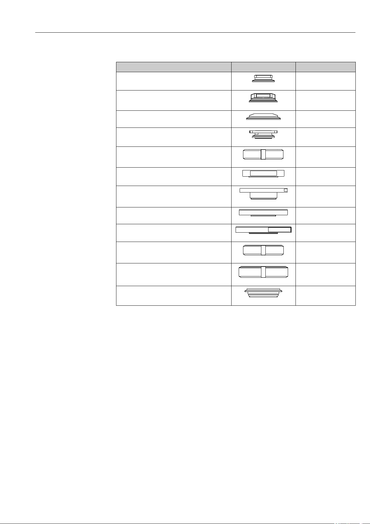
The following sections describe how to replace the seals. The following table serves as a
guide to the relevant sections.
A0023215 A0023216
A0023214 A0023213 A0023212
Molded seal process connection
(A)
O-rings - single
chamber (B)
Molded seal process
connection, double
chamber (C)
Molded seal front chamber (D)
Seals - inner
double chamber
(E)
Endress+Hauser 35
Page 36

Maintenance Cleanfit CPA875
5
8
2
3
4
6.5.1 Molded seal - process connection (A)
A0030357
23 Replacing seals, Part 1
1 Fixing screws
1. Release the four securing screws (, pos. 1).
24 Replacing seals, Part 2
2 Process connection
3 Sealing disk
4 Service chamber
5 Molded seal
6 Immersion tube
2. Remove the process connection (pos. 2).
3. Remove the molded seal (item 5) from the process connection.
4. Apply a thin layer of grease to the new molded seal (e.g. Klüber Paraliq GTE 703).
5. Slide the molded seal over the immersion tube (pos. 8) and into the guide groove of
the service chamber. Ensure that the molded seal is seated correctly.
6. Position the gasket (pos. 3) on the service chamber.
7. Place the process connection on the service chamber.
8. Tighten the four securing screws with a torque of 4 Nm.
36 Endress+Hauser
A0030365
Page 37

Cleanfit CPA875 Maintenance
1
2
3
4
5
6
7
4
8
9
6.5.2 O-rings - single chamber (B)
O-rings
A0030356
25 Replacing seals, Part 1
1 Fixing screws
1. Release the four securing screws.
2. Remove the service chamber (pos. 3) together with the process connection (pos. 2).
2
Process connection
3
Service chamber
4
O-rings (inner service chamber)
5
Molded seal
6
Positioning pin
7
O-ring (top of service chamber) (pneumatic drive
only)
8
Slide bushing (pneumatic drive only)
9
Leakage hole
A0030364
26 Replacing seals, Part 2
3. Use a tweezers to remove both o-rings (pos. 4) from the service chamber.
4. Pneumatic drive only: Use a thin screwdriver to push through the leakage hole (item
9). This pushes the slide bushing (item 8) out of the guide groove. You can now
remove the slide bushing using a tweezers.
5. Apply a thin layer of grease (e.g. Klüber Paraliq GTE 703) to the new O-rings and the
new slide bushing.
6. Pneumatic drive only: Insert the slide bushing into the middle guide groove.
7. Place both O-rings into the appropriate grooves in the service chamber.
Molded seal
1. Remove the molded seal (→ 26, 37 item 5) using a tweezers or long-nosed
pliers.
Endress+Hauser 37
Page 38

Maintenance Cleanfit CPA875
2. Apply a thin layer of grease to the molded seal and press the molded seal into the
guide groove of the immersion tube. Ensure that the molded seal is seated correctly.
If you insert a dummy sensor or circular rod (Ø 12 mm) until it protrudes just above
the seal, the molded seal cannot move upwards while it is being inserted.
Pneumatic drive
Pneumatic drive only:
1. Remove the O-ring (→ 26, 37 item 7). Apply a thin layer of grease to the new
o-ring, and position the o-ring in the guide groove.
2. Apply a thin layer of grease to the molded seal and press the molded seal into the
guide groove of the immersion tube. Ensure that the molded seal is seated correctly.
3. Mount the service chamber together with the process connection onto the assembly.
Pay attention to the positioning pin (item 6).
4. Tighten the four securing screws with a torque of 4 Nm.
38 Endress+Hauser
Page 39

Cleanfit CPA875 Maintenance
1
1
6.5.3 Molded seal - process connection, double chamber (C)
A0030358
27 Replacing seals, Part 1
1 Fixing screws
1. Release the four securing screws (, pos. 1).
A0030359
28 Replacing seals, Part 2
2 Process connection
3 Sealing disk
4 Molded seal
8 Immersion tube
2. Remove the process connection (pos. 2).
3. Remove the molded seal (pos. 4) from the process connection
4. Apply a thin layer of grease to the new molded seal (e.g. Klüber Paraliq GTE 703).
5. Slide the molded seal over the immersion tube (pos. 8) and into the guide groove of
the service chamber. Ensure that the molded seal is seated correctly.
6. Position the gasket (pos. 3) on the rinse chamber.
7. Place the process connection on the "inner" service chamber.
8. Tighten the four securing screws with a torque of 4 Nm.
Endress+Hauser 39
Page 40

Maintenance Cleanfit CPA875
1
2
3
5
8
6.5.4 Molded seal - "front" service chamber (D)
A0030360
29 Replacing seals, Part 1
1 Fixing screws
1. Release the four securing screws (item 1).
30 Replacing seals, Part 2
2 "Front" service chamber with process connection
3 Sealing disk
5 Molded seal
8 Immersion tube
A0030366
2. Remove the "front" service chamber together with the process connection (item 2).
3. Remove the molded seal (item 5) from the "front" chamber.
4. Apply a thin layer of grease to the new molded seal (e.g. Klüber Paraliq GTE 703).
5. Slide the molded seal over the immersion tube (pos. 8) and into the guide groove of
the service chamber. Ensure that the molded seal is seated correctly.
6. Position the gasket (pos. 3) on the front chamber.
7. Place the front chamber together with the process connection on the "inner" service
chamber.
40 Endress+Hauser
Page 41

Cleanfit CPA875 Maintenance
8. Tighten the four securing screws with a torque of 4 Nm.
Endress+Hauser 41
Page 42

Maintenance Cleanfit CPA875
1
1
2
3
2
6
6.5.5 Seals - inner double chamber (E)
O-ring in process connection
A0030361
31 Replacing seals, Part 1
1 Fixing screws
2 Service chamber with front chamber and process connection
1. Release the four securing screws (item 1).
2. Remove the service chamber with front chamber and process connection (pos. 2).
A0030363
32 Replacing seals, Part 2
2 "Inner" service chamber with "front" service chamber and process connection
3 O-ring
6 Positioning pin
3. Remove the O-ring (item 3).
4. Apply a thin layer of grease to the new o-ring (e.g Klüber Paraliq GTE 703) and
position the o-ring in the groove.
42 Endress+Hauser
Page 43

Cleanfit CPA875 Maintenance
4
5
Molded seal
A0030362
33 Replacing seals, Part 3
4 O-rings
5 Molded seal
1. Remove the molded seal (pos. 5) using a tweezers or long-nose pliers.
2. Apply a thin layer of grease to the new molded seal (e.g. Klüber Paraliq GTE 703).
3. Press the molded seal into the guide groove of the immersion tube. Ensure that the
molded seal is seated correctly.
If you insert a dummy sensor or circular rod (Ø 12 mm) until it protrudes just above
the seal, the molded seal cannot move upwards while it is being inserted.
O-rings in the immersion tube
1. Remove both O-rings (→ 33, 43 item 4).
2. Apply a thin layer of grease to the new o-rings, and position the o-rings in both
grooves.
3. Place the "inner" service chamber together with the "front" service chamber and
process connection on the assembly (pay attention to the positioning pin (item 6).
4. Tighten the four securing screws with a torque of 4 Nm.
Endress+Hauser 43
Page 44

Repairs Cleanfit CPA875
7 Repairs
WARNING
L
Danger resulting from improper repair
Damage to the assembly, which compromises pressure safety, must be repaired only by
‣
authorized and qualified personnel.
Damage to the drive can be repaired only at the place of manufacture. Repairs cannot
‣
be carried out onsite.
Following each repair and maintenance task, the assembly must be checked for leaks
‣
using appropriate procedures. Following this, the assembly must again comply with the
specifications in the technical data.
Replace all other damaged components immediately.
7.1 Spare parts
For more detailed information on spare parts kits, please refer to the "Spare Part Finding
Tool" on the Internet:
www.endress.com/spareparts_consumables
7.2 Return
The product must be returned if repairs or a factory calibration are required, or if the
wrong product was ordered or delivered. As an ISO-certified company and also due to legal
regulations, Endress+Hauser is obliged to follow certain procedures when handling any
returned products that have been in contact with medium.
To ensure swift, safe and professional device returns, please read the return procedures
and conditions at www.endress.com/support/return-material.
7.3 Disposal
The device contains electronic components and must therefore be disposed of in
accordance with regulations on the disposal of electronic waste.
Observe the local regulations.
44 Endress+Hauser
Page 45

Cleanfit CPA875 Accessories
G 1¼
12
Ø 42
Ø 25
Ø 25
12
Ø 42
G 1¼
15°
35 (1.38)
(1.65)
(0.98)
(0.47)
(1.65)
(0.98)
(0.47)
35 (1.38)
20
(0.79)
23.5
(0.93)
35
(1.38)
20
(0.79)
23.5
(0.93)
35
(1.38)
8 Accessories
The following are the most important accessories available at the time this
documentation was issued. For accessories not listed here, please contact your service
or sales office.
The following accessories can be ordered via the product structure (see ordering
information):
• Weld-in adapter G1¼, straight, 35 mm, 1.4435 (AISI 316 L), safety nozzle
• Weld-in adapter G1¼, angled, 35 mm, 1.4435 (AISI 316 L), safety nozzle
34 Weld-in adapter (safety nozzle), dimensions in mm (inch)
• Dummy plug G1¼, 1.4435 (AISI 316 L), FPM - FDA
• Sensor dummy 225 mm, 1.4435 (AISI 316 L), Ra = 0.38 µm
• Sensor dummy 360 mm, 1.4435 (AISI 316 L), Ra = 0.38 µm
• Kit, EPDM FDA seals only for process connection G1¼, wetted parts, single chamber
• Kit, FKM FDA seals only for process connection G1¼, wetted parts, single chamber
• Kit, FFKM FDA seals only for process connection G1¼, wetted parts, single chamber
• Kit, EPDM FDA seals, wetted parts, single chamber, not for process connection G1¼
• Kit, FKM FDA seals, wetted parts, single chamber, not for process connection G1¼
• Kit, FFKM FDA seals, wetted parts, single chamber, not for process connection G1¼
• Kit, EPDM FDA seals, wetted parts, double chamber, all process connections
• Kit, FKM FDA seals, wetted parts, double chamber, all process connections
• Kit, FFKM FDA seals, wetted parts, double chamber, all process connections
• Kit, seals not in contact with the medium
• Cable, plug-in, limit switch, M12, 5 m
• Cable, plug-in, limit switch, M12, 10 m
• Tool in case for installation/removal
A0028744
Endress+Hauser 45
Page 46

Accessories Cleanfit CPA875
8.1 Installation material for rinse connections
Filter set CPC310, CVC400
• Water filter (dirt trap) 100 µm, complete, incl. angle bracket
• Order No. 71031661
Pressure reducer kit
• Complete, incl. manometer and angle bracket
• Order No. 51505755
Hose connection set G¼, DN 12
• 1.4404 (AISI 316L) 2 x
• Order No. 51502808
Hose connection set G¼, DN 12
• PVDF (2 x)
• Order No. 50090491
46 Endress+Hauser
Page 47

Cleanfit CPA875 Accessories
8.2 Sensors
8.2.1 pH sensors
Orbisint CPS11D / CPS11
• pH electrode for process technology
• Optional SIL version for connecting to SIL transmitter
• With dirt-repellent PTFE diaphragm
• Product Configurator on the product page: www.endress.com/cps11d or
www.endress.com/cps11
Technical Information TI00028C
Memosens CPS31D
• pH electrode with gel-filled reference system with ceramic diaphragm
• Product Configurator on the product page: www.endress.com/cps31d
Technical Information TI00030C
Ceraliquid CPS41D / CPS41
• pH electrode with ceramic junction and KCl liquid electrolyte
• Product Configurator on the product page: www.endress.com/cps41d or
www.endress.com/cps41
Technical Information TI00079C
Ceragel CPS71D / CPS71
• pH electrode with reference system including ion trap
• Product Configurator on the product page: www.endress.com/cps71d or
www.endress.com/cps71
Technical Information TI00245C
Orbipore CPS91D / CPS91
• pH electrode with open aperture for media with high dirt load
• Product Configurator on the product page: www.endress.com/cps91d or
www.endress.com/cps91
Technical Information TI00375C
8.2.2 ORP sensors
Orbisint CPS12D / CPS12
• ORP sensor for process technology
• Product Configurator on the product page: www.endress.com/cps12d or
www.endress.com/cps12
Technical Information TI00367C
Ceraliquid CPS42D / CPS42
• ORP electrode with ceramic junction and KCl liquid electrolyte
• Product Configurator on the product page: www.endress.com/cps42d or
www.endress.com/cps42
Technical Information TI00373C
Ceragel CPS72D / CPS72
• ORP electrode with reference system including ion trap
• Product Configurator on the product page: www.endress.com/cps72d or
www.endress.com/cps72
Technical Information TI00374C
Endress+Hauser 47
Page 48

Accessories Cleanfit CPA875
8.2.3 pH ISFET sensors
Tophit CPS441D / CPS441
• Sterilizable ISFET sensor for low-conductivity media
• Liquid KCl electrolyte
• Product Configurator on the product page: www.endress.com/cps441d or
www.endress.com/cps441
Technical Information TI00352C
Tophit CPS471D / CPS471
• Sterilizable and autoclavable ISFET sensor for food and pharmaceutics, process
engineering
• Water treatment and biotechnology
• Product Configurator on the product page: www.endress.com/cps471d or
www.endress.com/cps471
Technical Information TI00283C
Tophit CPS491D / CPS491
• ISFET sensor with open aperture for media with high dirt load
• Product Configurator on the product page: www.endress.com/cps491d or
www.endress.com/cps491
Technical Information TI00377C
8.2.4 pH and ORP combined sensors
Memosens CPS16D
• Combined pH/ORP sensor for process technology
• With dirt-repellent PTFE diaphragm
• With Memosens technology
• Product Configurator on the product page: www.endress.com/cps16D
Technical Information TI00503C
Memosens CPS76D
• Combined pH/ORP sensor for process technology
• Hygienic and sterile applications
• With Memosens technology
• Product Configurator on the product page: www.endress.com/cps76d
Technical Information TI00506C
Memosens CPS96D
• Combined pH/ORP sensor for chemical processes
• With poison-resistant reference with ion trap
• With Memosens technology
• Product Configurator on the product page: www.endress.com/cps96d
Technical Information TI00507C
8.2.5 Conductivity sensors
Memosens CLS82D
• Four-electrode sensor
• With Memosens technology
• Product Configurator on the product page: www.endress.com/cls82d
Technical Information TI01188C
48 Endress+Hauser
Page 49

Cleanfit CPA875 Accessories
8.2.6 Oxygen sensors
Oxymax COS22D / COS22
• Sterilizable sensor for dissolved oxygen
• With Memosens technology or as an analog sensor
• Product Configurator on the product page: www.endress.com/cos22d or
www.endress.com/cos22
Technical Information TI00446C
Endress+Hauser 49
Page 50

Technical data Cleanfit CPA875
p [bar]
T[°C]
20 8060
40
T[°F]
p [psi]
0
32
0
0
16232
100 120 140
68 104 140 176
212
248 284
A
B
9 Technical data
9.1 Environment
Ambient temperature
-10 to +70 °C (+10 to +160 °F)
range
Storage temperature -10 to +70 °C (+10 to +160 °F)
9.2 Process
Process temperature -10 to 140 °C (14 to 284 °F)
Process pressure Pneumatic drive 16 bar (232 psi) up to 140 °C (284 °F)
Manual drive 8 bar (116 psi) up to 140 °C (284 °F)
The service life of the seals is reduced if process temperatures are constantly high or if
SIP is used. The other process conditions may also reduce the service life of the seals.
Pressure-temperature ratings
35 Pressure-temperature ratings for pneumatic drive
A Dynamic range
B Static range
50 Endress+Hauser
A0029360-EN
Page 51

Cleanfit CPA875 Technical data
p [bar]
T[°C]
20 8060
40
T[°F]
p [psi]
0
32
0
0
8
100 120 140
68 104 140 176
212
248 284
A
B
A0029361-EN
36 Pressure-temperature ratings for manual drive
A Dynamic range
B Static range
Endress+Hauser 51
Page 52

Technical data Cleanfit CPA875
9.3 Mechanical construction
Design, dimensions → Section "Installation"
Weight
Materials
Depends on version:
Pneumatic drive: 3.8 to 6 kg (8.4 to 13.2 lbs) depending on version
Manual drive: 3 to 4.5 kg (6.6 to 9.9 lbs) depending on version
In contact with medium
Seals: EPDM-FDA (USP Class VI) / FKM-FDA (USP Class VI) /
FFKM-FDA (USP Class VI)
Immersion tube: Stainless steel 1.4435 (AISI 316L) Ra < 0.76 / Ra < 0.38
Process connection, service
chamber
Rinse connections: Stainless steel 1.4435 (AISI 316L)
Not in contact with medium
Manual drive: Stainless steel 1.4301 (AISI 304) or 1.4404 (AISI 316L), plastics PPS
CF15, PBT, PP
Pneumatic drive: Stainless steel 1.4301 (AISI 304) or 1.4404 (AISI 316L), plastics PBT,
PP
Stainless steel 1.4435 (AISI 316L) Ra < 0.76
Sensors
Limit position switches Switching element function: NAMUR NC contact (inductive)
Short version Gel sensors, ISFET 225 mm
KCl sensors 225 mm
Long version Gel sensors, ISFET 225 mm
Gel sensors, ISFET 360 mm
KCl sensors 360 mm
Switching distance: 1,5 mm (0.06 ")
Nominal voltage: 8 V
Switching frequency: 0 to 5000 Hz
Housing material: Stainless steel
52 Endress+Hauser
Page 53

Index
Index
A
Accessories ................................ 45
Approvals .................................. 9
C
Certificates ................................. 9
Cleaning .................................. 33
Cleaning agent ............................. 34
Cleaning process seal .........................31
Connection
Pneumatics ............................. 19
D
Designated use .............................. 5
Dimensions ................................11
Disposal .................................. 44
F
Failure of compressed air supply ................ 31
I
Immersion depths ........................... 14
Incoming acceptance .......................... 7
Installation ............................. 10, 16
Installation conditions ........................ 10
Installing the sensor ......................... 23
S
Safety instructions ............................5
Scope of delivery ............................. 7
Seals .....................................35
Spare parts ................................ 44
Symbols ................................... 4
T
Technical data ..............................50
U
Use .......................................5
W
Warnings .................................. 4
L
Limit position switches ....................... 21
M
Maintenance ...............................32
Maintenance intervals ........................32
Manual operation ........................... 30
Measuring system ........................... 16
N
Nameplate ................................. 8
O
O-rings ................................... 35
Operating elements ..........................29
Operation ................................. 28
Manual ................................ 30
Pneumatic: ..............................30
P
Pneumatic connection ........................ 19
Pneumatic operation ......................... 30
Post-installation check ....................... 27
Product identification ......................... 7
R
Repairs ................................... 44
Return ................................... 44
Rinse connections ........................... 20
Endress+Hauser 53
Page 54

Page 55

Page 56

*71324469*
71324469
www.addresses.endress.com
 Loading...