

Endress+Hauser CPA871 Specifications
TI01191C/07/EN/05.19
71440289
2019-05-14
Products Solutions Services
Technical Information
Cleanfit CPA871
Flexible retractable process assembly for water,
wastewater, chemical industry and heavy industry
Application
Cleanfit CPA871 is a flexible process retractable assembly for
applications with standard 12 mm sensors for pH and redox.
The assembly was developed to guarantee maximum safety in:
• Water and wastewater including sea water
• Chemical industry
• Oil and gas
• Electricity and energy
• Hazardous areas
• Primaries and metals
Your benefits
• Maximum operational safety: Intelligent functions ensure
that the assembly is not inserted into the process without
the sensor or unintentionally retracted from the process if
the assembly is in measuring position.
• Suitable for demanding applications: The optional
immersion chamber eliminates problems associated with
media that form buildup.
• Robust assembly design: The metallic support housing
ensures that the service chamber is mechanically stable.
• Flexible in adapting to your process: A wide range of process
connections and materials in contact with the medium; for
corrosive media and hazardous areas also.

Function and system design
Cleanfit CPA871
Mode of operation
Design
Safety function
With the Cleanfit CPA871 retractable assembly, you can carry out pH, ORP and other measurements
reliably using suitable sensors. You can remove, clean, sterilize or calibrate/adjust the sensors
without interrupting the process.
The assembly can be installed in both vessels and pipes.
The retractable assembly has a modular design and can therefore be flexibly adapted to a wide array
of applications. It is available with both a manual and a pneumatic drive.
A choice of two chamber systems is available for the assembly:
• Standard version or
• Immersion chamber version
It is possible to choose between the following strokes for the electrode guide:
• 36 mm for standard version and immersion chamber version
• 78 mm for standard version
All common process connections are available:
Clamp/flange EN1092-1/flange ASME B16.5/flange JIS B2220/dairy fitting/thread
Locking mechanism without sensor
If the sensor is not installed, it is not possible to pneumatically or manually move the assembly from
the service position to the measuring position.
Manual or pneumatic drive
The sensor can be driven both manually and pneumatically. The manual drive has a self-retaining
thread to hold the sensor in any intermediate position. The manual drive can be used for process
pressures up to 8 bar (116 psi). The pneumatic drive can be used for process pressures up to
16 bar (232 psi).
Limit position locking if compressed air fails
If the compressed air fails in pneumatic assemblies, the assembly remains in the position previously
selected. The process pressure cannot force it out of the measuring position and into an intermediate
position.
Limit position locking with manual drive
For position locking, the manual version has an unlocking button in both the measuring position and
the service position.
Impossible to remove sensor in the measuring position
The protection cap for covering the sensor has the following functions:
• Mechanical sensor safety
• Prevents sensor removal in the assembly measuring position
The bottom part of the protection cap is partly inserted into the drive and cannot be opened as a
result.
Non-rotating sensor guide
During insertion/retraction, the position of the ridges of the immersion tube in the area of the
sensor head retains the pre-setting once selected. This guarantees optimum and clear positioning of
the sensor in the process and during cleaning.
Limit position detection (can be retrofitted)
In the case of assemblies with a pneumatic drive, the service and measuring position of the sensor
are detected inductively and reported to connected systems (only for the measuring position in the
case of the manual drive assembly).
2 Endress+Hauser

Cleanfit CPA871
1
2
3
5
6
7
4
1
2
3
4
5
6
7
8
2
3
4
Elements
The assembly is available with a manual or pneumatic drive.
A0029812
1 Assembly with manual drive (without protection
cap)
1 Rinse connection
2 Connection for limit position switch
3 Manual drive (fulcrum shaft)
4 Unlocking button (service position)
5 Fastening ring for protective cap
6 Unlocking button (measuring position)
7 Rinse connection
2 Assembly with pneumatic drive (without
1 Rinse connection
2 Automatic limit position lock, process
3 Connection for limit position switch
4 Automatic limit position lock, service
5 Fastening ring for protective cap
6 Pneumatic connection (move to measuring
7 Pneumatic connection (move to service position)
8 Rinse connection
A0023912
protective cap)
position)
Measuring system
Endress+Hauser 3
3 Measuring system (example)
1 Cleanfit assembly CPA871
2 Measuring cable
3 Liquiline CM44x transmitter
4 Sensor
A0029620
Cleanfit CPA871
2
3
4
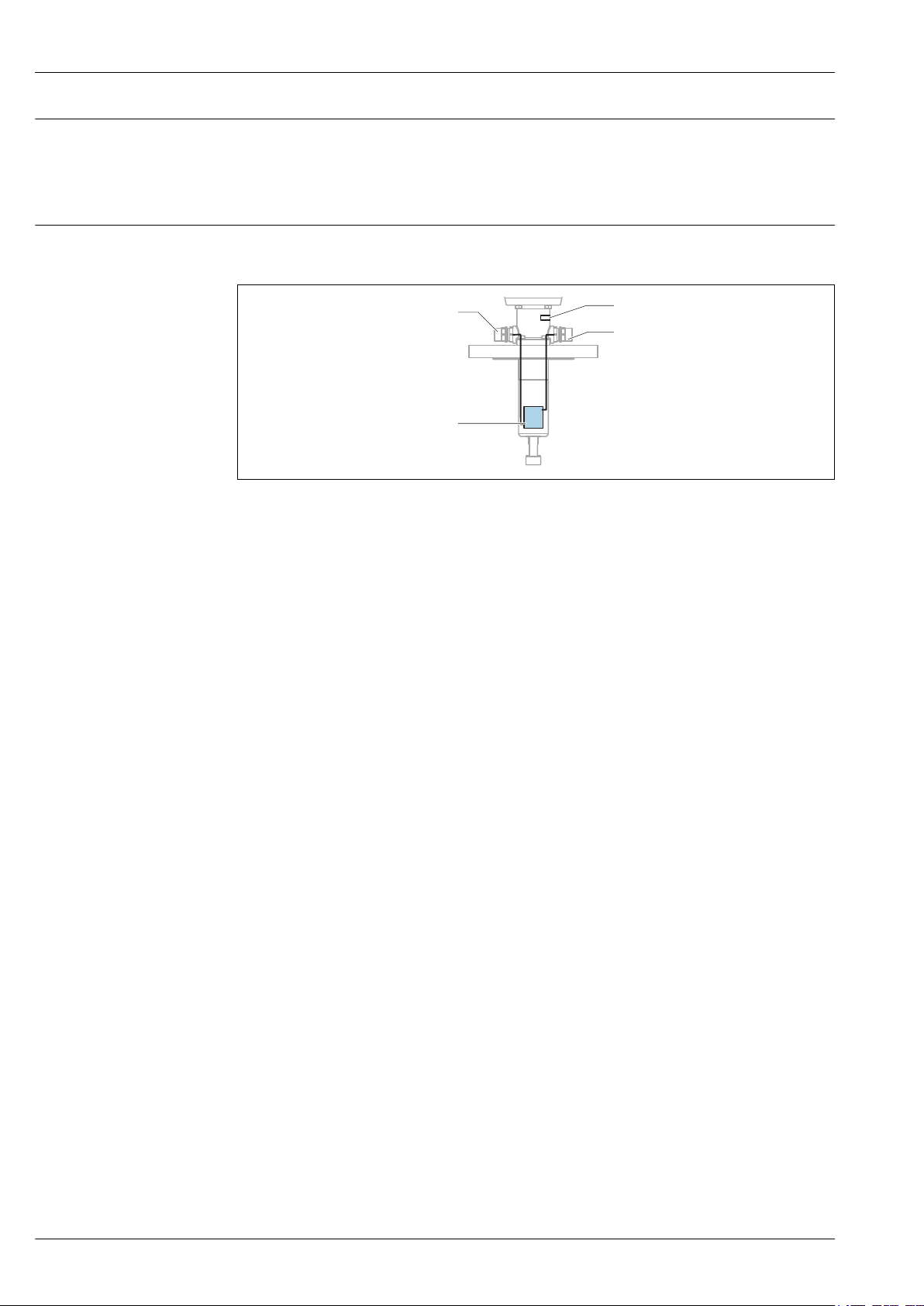
Immersion chamber
Assignment of rinse connections
The special immersion chamber version is the perfect solution when the sensor descends to greater
immersion depths in media that cause buildup and media with a tendency to form condensation. In
the process medium, the sensor guide containing the installed sensor is almost completely
surrounded by the service chamber. This means that there is minimal contact with the medium. The
seals are thus protected from damage when the sensor is moving from measuring to service position.
The inlet and outlet of the service chamber are fixed. The outlet of the service chamber is located
under the leakage borehole. The leakage hole is sealed with an M5 screw.
A0028521
4 Connection of service chamber in the immersion chamber version
1 Service chamber
2 Service chamber inlet
3 Leakage hole
4 Service chamber outlet
4 Endress+Hauser
Cleanfit CPA871
1
2
3
4
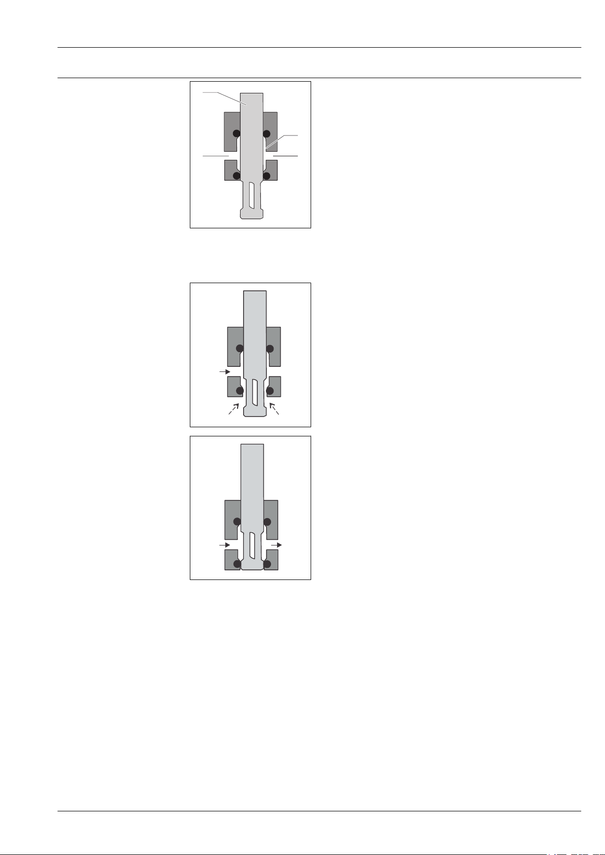
Service chamber
In measuring position, the service chamber is separated from
the process by the process seals and sensor guide.
No process medium can get into the service chamber.
A0024239
1 Service chamber
2 Service chamber outlet
3 Service chamber inlet
4 Sensor guide
When the assembly is moving from measuring to service
position (or the other way around), the service chamber is no
longer separated from the process. Now process medium can
get into the service chamber.
To prevent this, you can rinse the service chamber with a
sealing medium via the service chamber inlet. This also means
that process medium, which may contain solid particles, does
not need to be removed via the service chamber.
A0024240
A0024241
In service position, the service chamber is separated from the
process.
Endress+Hauser 5
Cleanfit CPA871
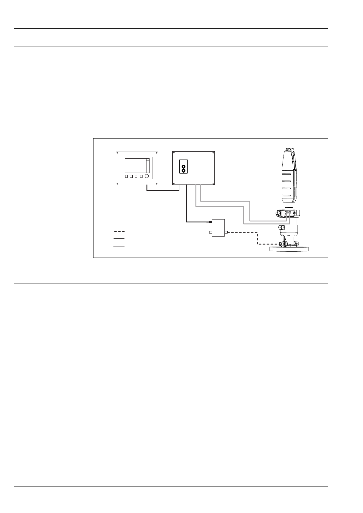
Liquiline CM444
Cleanfit Control
Cleaning medium
Electrical connection
Pneumatical connection
Cleanfit Control
Integration in an automatic measuring system
Cleanfit Control converts electrical signals into pneumatic signals. Signals coming from the relays or
outputs of the transmitter are used to control pneumatically-operated retractable assemblies or
pumps. Pilot valves are used for this purpose.
Cleanfit Control allows automatic cleaning of sensors installed in retractable assemblies. This means
that sensor performance can be maintained at a high level without any interruption to the process.
It is the function of the Cleanfit Control CYC25 to integrate the actuators into the cleaning program
in a safety-oriented manner. That is why the actuators, i.e. assembly, valves and pumps, are not
connected directly via the relays to the Liquiline CM44x. Instead they are connected to the Cleanfit
Control CYC25. The 24V DC power supply to these actuators, as well as the compressed air supply,
are provided by the customer.
Control unit Air-Trol 500
A0030123-EN
5 Control of cleaning with Cleanfit Control
Cleanfit Control is available as accessory.
Air-Trol 500 allows you to move all pneumatically-controlled retractable assemblies manually.
• Easy installation
• Purely pneumatic functional unit
• Measuring or service mode of assembly:
• Simple toggle switch
• Optical display
• Push-button switch for pneumatic valve for cleaning agent, used to clean sensor
Air-Trol 500 is available as accessory.
6 Endress+Hauser

Cleanfit CPA871
Installation
Orientation
Pneumatic connections for automatic operation
The assembly is designed for installation on tanks and pipes. Suitable process connections must be
available for this.
NOTICE
Frost damage to the assembly
If used outdoors, ensure that water cannot penetrate the drive.
‣
The assembly is designed in such a way that there are no restrictions with regard to the orientation.
The sensor that is used can restrict the orientation.
Ensure compliance with the Operating Instructions of the sensor installed.
Prerequisites:
• Air pressure 4 to 7 bar (absolute pressure) (58 to 102 psi)
• Compressed air quality in accordance with ISO 8573-1:2001
Quality class 3.3.3 or 3.4.3
• Solids class 3 (max. 5 μm, max. 5 mg/m3, contamination with particles)
• Water content for temperatures ≥ 15 °C: Class 4 pressure condensation point 3 °C or lower
• Water content for temperatures of 5 to 15 °C: Class 3 pressure condensation point -20 °C or lower
• Oil content: Class 3 (max. 1 mg/m3)
• Air temperature: 5 °C or higher
• No continuous air consumption
• Minimum nominal diameter of air pipes: 2 mm (0.08 ")
A dual-operating cylinder is used to operate the pneumatic drive.
An automatic limit position lock both in service and measuring position secures the assembly to
prevent it from moving inadvertently in the event of a failure in the control air. The assembly
remains in the relevant position.
Connection: Push connector M5, hose 4/2 mm OD/ID (adapter for 6/4 mm OD/ID enclosed)
Rinse connection
NOTICE
Air pressure too high
Damage to seals.
Connect a pressure-reducing valve upstream if the air pressure is likely to rise to above 7 bar
‣
(absolute pressure) (102 psi) (even short pressure surges).
The service chamber connections make it possible to rinse the chamber (including the sensor) with
water or cleaning solution. The pressure difference between the sealing water and process must not
exceed 6 bar (87 psi).
The sealing water pressure must not exceed 8 bar (116 psi) in manual mode and 16 bar (232 psi) in
pneumatic mode.
Install a pressure-reducing valve upstream if there is a possibility that the sealing water
pressure will increase to more than(8 bar (116 psi) or 16 bar (232 psi)) (including any short
pressure surges).
NOTICE
Pressure difference too high between process and wastewater system or if rinse connections
are not properly connected.
Damage to seals
Close rinse connections.
‣
Pipe-fit rinse connections.
‣
Use sealing water function.
‣
Environment
Ambient temperature range
Endress+Hauser 7
-10 to +70 °C (+10 to +160 °F)

Cleanfit CPA871
Storage temperature
-10 to +70 °C (+10 to +160 °F)
8 Endress+Hauser
Cleanfit CPA871
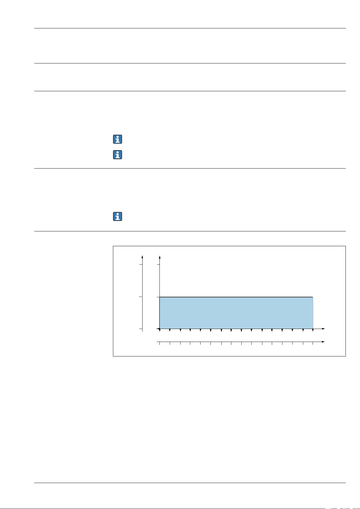
p [bar]
T[°C]
20 80
60
40
T[°F]
p [psi]
0
32
0
0
16232
100 120 140
68 104
140
176
212
248 284
8
A
Process
Process temperature
Process pressure for pneumatic drive
Process pressure for manual drive
Pressure-temperature ratings
-10 to +140 °C (14 to 284 °F) for all materials except PVDF and conductive PVDF
-10 to +100 / 90 °C (14 to 212 / 194 °F) for PVDF and conductive PVDF materials
Materials: 1.4404, Alloy C22, PEEK
Basic and immersion chamber version: 16 bar (232 psi) up to 140 °C (284 °F)
Materials: PVDF, conductive PVDF
Basic version: 16 bar (232 psi) up to 100 °C (212 °F)
Immersion chamber version: 4 bar (58 psi) to 90 °C (194 °F)
The service life of the seals is reduced if process temperatures are constantly high or if SIP is
used. The other process conditions may also reduce the service life of the seals.
Depending on the version, the process pressure must be reduced to insert/retract the assembly.
Materials: 1.4404, Alloy C22, PEEK
Basic and immersion chamber version: 8 bar (116 psi) up to 140 °C (284 °F)
Materials: PVDF, conductive PVDF
Basic version: 8 bar (116 psi) up to 100 °C (212 °F)
Immersion chamber version: 4 bar (58 psi) to 90 °C (194 °F)
The service life of the seals is reduced if process temperatures are constantly high or if SIP is
used. The other process conditions may also reduce the service life of the seals.
Manual drive, movement of assembly up to 8 bar
6 Pressure temperature ratings for basic and immersion chamber version for materials 1.4404, Alloy C22
and PEEK
A Basic and immersion chamber version
Endress+Hauser 9
A0039156
 Loading...