

Page 1
BA00178C/07/EN/13.18
71436282
2018-08-31
Products Solutions Services
Operating Instructions
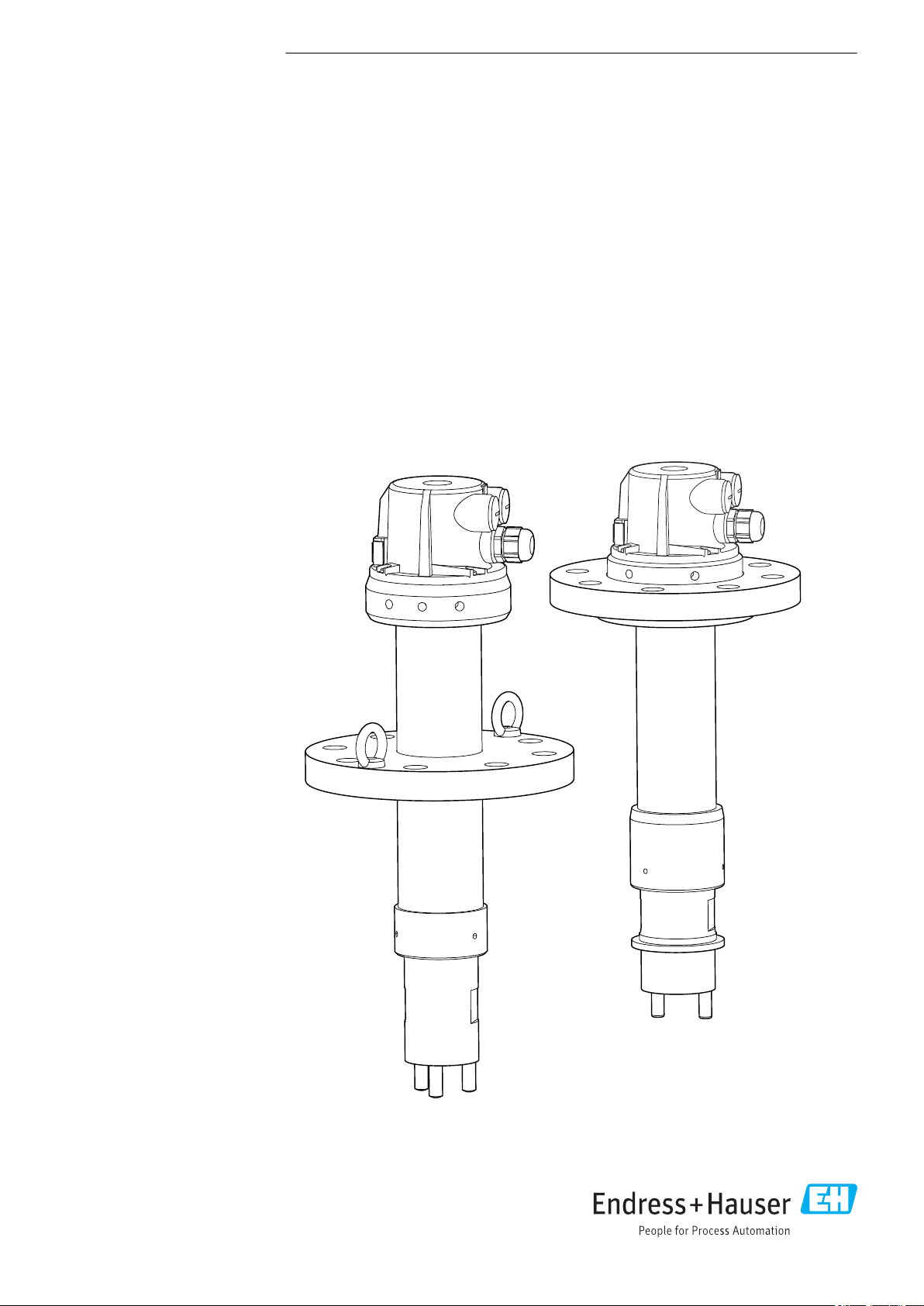
Dipfit CPA140
Immersion assembly for pH or ORP sensors
Page 2

Page 3

Dipfit CPA140 Table of contents
Table of contents
1 About this document ................ 4
1.1 Warnings ............................ 4
1.2 Symbols used .......................... 4
1.3 Symbols on the device ................... 4
2 Basic safety instructions ............ 5
2.1 Requirements for the personnel ............ 5
2.2 Designated use ........................ 5
2.3 Workplace safety ....................... 5
2.4 Operational safety ...................... 6
2.5 Product safety ......................... 6
3 Product description ................. 7
3.1 PVDF version .......................... 7
3.2 Stainless steel version ................... 8
4 Incoming acceptance and product
identification ....................... 9
4.1 Incoming acceptance .................... 9
4.2 Scope of delivery ....................... 9
4.3 Product identification .................... 9
Index .................................. 29
5 Installation ....................... 11
5.1 Installation conditions .................. 11
5.2 Mounting the sensor ................... 15
5.3 Mounting the assembly in the process ...... 18
5.4 Post-installation check .................. 18
6 Maintenance ...................... 19
6.1 Cleaning the assembly .................. 19
6.2 Cleaning agent ....................... 19
6.3 Replacing the seal ..................... 20
6.4 Replacing the GORE-TEX® filter ........... 22
7 Repair ............................ 24
7.1 Spare parts .......................... 24
7.2 Return .............................. 24
7.3 Disposal ............................ 24
8 Accessories ....................... 25
8.1 Sensors (selection) ..................... 25
8.2 Measuring cable ...................... 26
8.3 KCl supply vessel ...................... 26
8.4 Cleaning ............................ 26
9 Technical data .................... 27
9.1 Environment ......................... 27
9.2 Process ............................. 27
9.3 Mechanical construction ................ 27
Endress+Hauser 3
Page 4
About this document Dipfit CPA140
1 About this document
1.1 Warnings
Structure of information Meaning
DANGER
L
Causes (/consequences)
If necessary, Consequences of
non-compliance (if applicable)
Corrective action
‣
WARNING
L
Causes (/consequences)
If necessary, Consequences of
non-compliance (if applicable)
Corrective action
‣
CAUTION
L
Causes (/consequences)
If necessary, Consequences of
non-compliance (if applicable)
Corrective action
‣
NOTICE
Cause/situation
If necessary, Consequences of
non-compliance (if applicable)
Action/note
‣
This symbol alerts you to a dangerous situation.
Failure to avoid the dangerous situation will result in a fatal or serious
injury.
This symbol alerts you to a dangerous situation.
Failure to avoid the dangerous situation can result in a fatal or serious
injury.
This symbol alerts you to a dangerous situation.
Failure to avoid this situation can result in minor or more serious injuries.
This symbol alerts you to situations which may result in damage to
property.
1.2 Symbols used
Symbol Meaning
Additional information, tips
Permitted or recommended
Not permitted or not recommended
Reference to device documentation
Reference to page
Reference to graphic
Result of a step
1.3 Symbols on the device
Symbol Meaning
Reference to device documentation
4 Endress+Hauser
Page 5

Dipfit CPA140 Basic safety instructions
2 Basic safety instructions
2.1 Requirements for the personnel
• Installation, commissioning, operation and maintenance of the measuring system may
be carried out only by specially trained technical personnel.
• The technical personnel must be authorized by the plant operator to carry out the
specified activities.
• The electrical connection may be performed only by an electrical technician.
• The technical personnel must have read and understood these Operating Instructions
and must follow the instructions contained therein.
• Faults at the measuring point may only be rectified by authorized and specially trained
personnel.
Repairs not described in the Operating Instructions provided must be carried out only
directly at the manufacturer's site or by the service organization.
2.2 Designated use
The assembly is designed for the installation of pH, ORP, oxygen and temperature sensors
in vessels.
The main areas of application involve pH, oxygen or ORP measurement in the following
processes:
• Chemical industry, e.g. in
• production of synthetic materials and dyes
• production or pesticides and fertilizers
• oil or wastewater separation
• condensate treatment
• Power stations and incinerator plants, e.g. in
• cooling water monitoring
• flue gas cleaning
• Metal extraction and metal processing
Thanks to its design, it can be operated in pressurized systems (→ 27).
Use of the device for any purpose other than that described, poses a threat to the safety of
people and of the entire measuring system and is therefore not permitted.
The manufacturer is not liable for damage caused by improper or non-designated use.
2.3 Workplace safety
2.3.1 General notes
As the user, you are responsible for complying with the following safety conditions:
• Installation guidelines
• Local standards and regulations
2.3.2 Notes on installation in pressurized systems
Risk of injury from high pressure, high temperature or chemical hazards if process medium
escapes!
Do not exceed the permitted maximum process pressure.
‣
Prior to installing and removing the assembly, depressurize the system.
‣
Check glands and lines regularly for leaks and damage.
‣
Endress+Hauser 5
Page 6

Basic safety instructions Dipfit CPA140
2.4 Operational safety
Before commissioning the entire measuring point:
1. Verify that all connections are correct.
2. Ensure that electrical cables and hose connections are undamaged.
3. Do not operate damaged products, and protect them against unintentional operation.
4. Label damaged products as defective.
During operation:
If faults cannot be rectified:
‣
products must be taken out of service and protected against unintentional operation.
2.5 Product safety
The product is designed to meet state-of-the-art safety requirements, has been tested, and
left the factory in a condition in which it is safe to operate. The relevant regulations and
European standards have been observed.
6 Endress+Hauser
Page 7
Dipfit CPA140 Product description
2
3
4
5
1
6
7
8
3 Product description
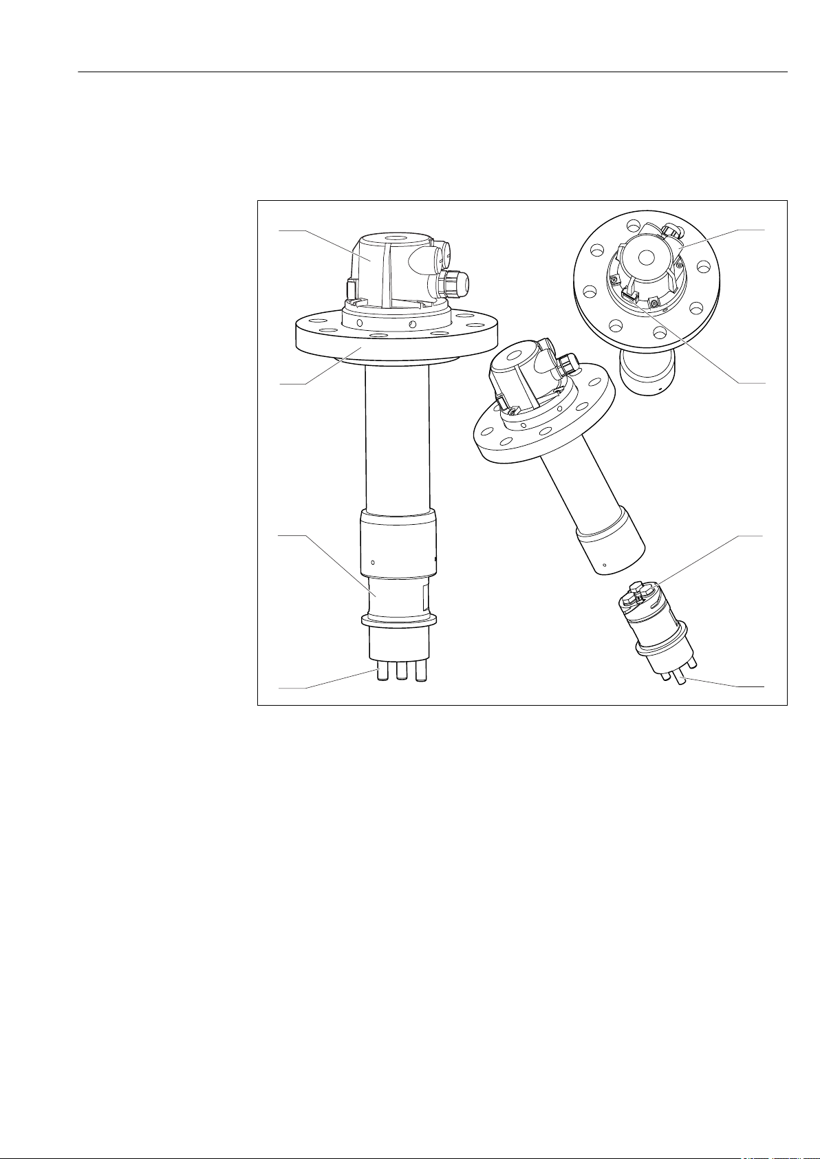
3.1 PVDF version
1 PVDF version
1 Assembly head
2 Cable gland Pg 13.5 and 2x dummy plug Pg 16
3 GORE-TEX® filter
4 3 sensor slots for 120 mm sensors
5 Potential matching pin
6 Shock-protection stud
7 Sensor holder with bayonet lock
8 Lap joint flange, depending on version
A0037531
Endress+Hauser 7
Page 8
Product description Dipfit CPA140
2
3
4
5
1
6
7
8
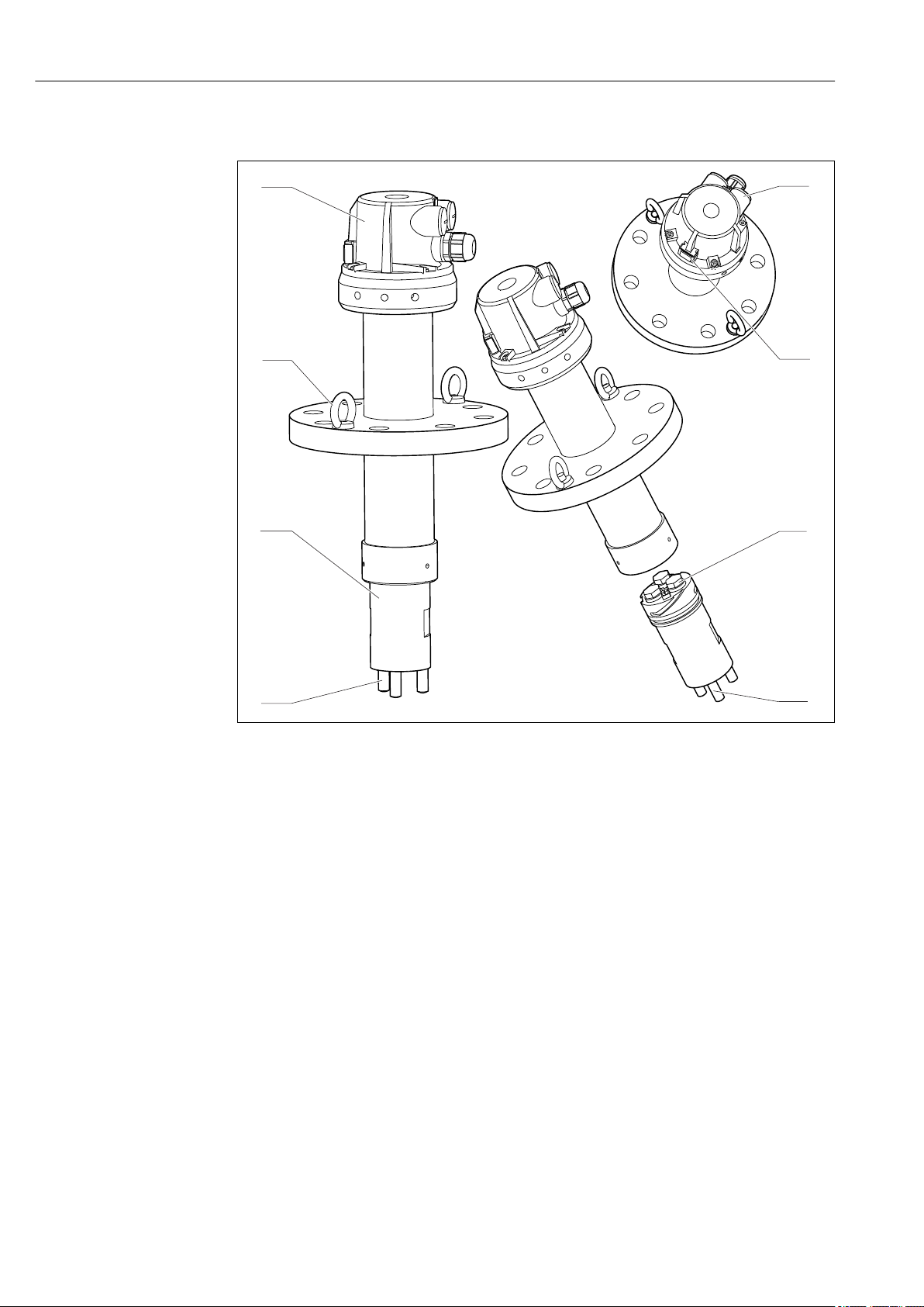
3.2 Stainless steel version
A0037532
2 Stainless steel version
1 Assembly head
2 Cable gland Pg 13.5 and 2x dummy plug Pg 16
3 GORE-TEX® filter
4 3 sensor slots for 120 mm sensors
5 Potential matching pin
6 Shock-protection stud
7 Sensor holder with bayonet lock
8 Installation aids (screw-in lifting eyes) and fixed flange, depending on the version
8 Endress+Hauser
Page 9

Dipfit CPA140 Incoming acceptance and product identification
4 Incoming acceptance and product
identification
4.1 Incoming acceptance
1. Verify that the packaging is undamaged.
Notify the supplier of any damage to the packaging.
Keep the damaged packaging until the issue has been resolved.
2. Verify that the contents are undamaged.
Notify the supplier of any damage to the delivery contents.
Keep the damaged goods until the issue has been resolved.
3. Check that the delivery is complete and nothing is missing.
Compare the shipping documents with your order.
4. Pack the product for storage and transportation in such a way that it is protected
against impact and moisture.
The original packaging offers the best protection.
Make sure to comply with the permitted ambient conditions.
If you have any questions, please contact your supplier or your local Sales Center.
4.2 Scope of delivery
The scope of delivery comprises:
• Ordered version of assembly
• Operating Instructions
4.3 Product identification
4.3.1 Nameplate
The nameplate provides you with the following information on your device:
• Manufacturer identification
• Order code
• Extended order code
• Serial number
• Ambient and process conditions
• Safety information and warnings
Compare the information on the nameplate with the order.
‣
4.3.2 Product identification
Product page
www.endress.com/cpa140
Interpreting the order code
The order code and serial number of your product can be found in the following locations:
• On the nameplate
• In the delivery papers
Endress+Hauser 9
Page 10

Incoming acceptance and product identification Dipfit CPA140
Obtaining information on the product
1. Go to www.endress.com.
2. Call up the site search (magnifying glass).
3. Enter a valid serial number.
4. Search.
The product structure is displayed in a popup window.
5. Click on the product image in the popup window.
A new window (Device Viewer) opens. All of the information relating to your
device is displayed in this window as well as the product documentation.
4.3.3 Certificates and approvals
Pressure Equipment Directive 2014/68/EU
The assembly has been manufactured according to good engineering practice as per Article
4, Paragraph 3 of the Pressure Equipment Directive 2014/68/EU and is therefore not
required to bear the CE label.
Inspection certificate
A test certificate 3.1 in accordance with EN 10204 is supplied depending on the version (→
Product Configurator on the product page).
4.3.4 Manufacturer's address
Endress+Hauser Conducta GmbH+Co. KG
Dieselstraße 24
D-70839 Gerlingen
10 Endress+Hauser
Page 11

Dipfit CPA140 Installation
b
c
d
e
a
b
c
d
e
a
A B
5 Installation
5.1 Installation conditions
5.1.1 Dimensions
3 Flange dimensions, → Table
A Stainless steel version
B PVDF version
Stainless steel assembly version PVDF assembly version
DN80 PN16 ANSI 3"
150 lbs
a [mm (in)] 18 (0.71) 19 (0.75) 19 (0.75) 18 (0.71) 19 (0.75) 19 (0.75)
b [mm (in)] 20 (0.79) 23.8 (0.94) 18 (0.71) 22 (0.87) 22 (0.87) 18 (0.71)
c [mm (in)] 63.5 (2.50) 63.5 (2.50) 63.5 (2.50) 110 (4.33) 110 (4.33) 110 (4.33)
d [mm (in)] 160 (6.30) 152.4 (6.00) 150 (5.91) 160 (6.30) 152 (5.98) 150 (5.91)
e [mm (in)] 200 (7.87) 190.5 (7.50) 185 (7.28) 200 (7.87) 200 (7.87) 185 (7.28)
Screws M16 M16 M16 M16 M16 M16
Bore holes 8 4 4 8 4 4
JIS 10K 80A DN80 PN16 ANSI 3"
150 lbs
JIS 10K 80A
A0037380
Endress+Hauser 11
Page 12

Installation Dipfit CPA140
22 (8.74)2
y
! (4.25)108
!63.5 (2.50)
!69 (2.72)
20 (0.79)
25 (0.98)
4 Stainless steel version, dimensions in mm (in)
y Immersion depth, → Configurator on product page
A0037561
12 Endress+Hauser
Page 13

Dipfit CPA140 Installation
108 (4.25)
y
! 25 (4.92)1
! . (2.50)63 5
!75 (2.95)
!74 (2.91)
25 (0.98)
5 PVDF version, dimensions in mm (in)
y Immersion depth, → Configurator on product page
A0037563
Endress+Hauser 13
Page 14

Installation Dipfit CPA140
1 2
3
5
4
5.1.2 Measuring system
A complete measuring system comprises:
• Immersion assembly Dipfit CPA140
• 1-3 pH, ORP, pH/ORP combined sensors or temperature sensors (12 mm), e.g. CPS11D,
CPS12D
• 1-3 measuring cables, e.g. CYK10 or CPK9
• Transmitter, e.g. Liquiline CM442
Optional:
Extension cable, e.g. CYK11
6 Example of a measuring system (process and process connections are not illustrated)
1 Immersion assembly Dipfit CPA140, here as PVDF version
2 Transmitter CM442
3 Sensor cable CYK10
4 pH sensor CPS11D
5 ORP sensor CPS12D
A0037542
14 Endress+Hauser
Page 15

Dipfit CPA140 Installation
5.2 Mounting the sensor
The PVDF version is illustrated in the graphics below. The sensor mounting procedure
is identical for the stainless steel version.
1.
Release 4 screws (M4), remove the cover.
2.
Only for the PVDF version:
Remove the lap joint flange.
3.
Unscrew the sensor holder (bayonet lock).
Endress+Hauser 15
Page 16

Installation Dipfit CPA140
4.
Remove the dummy plug along with the O-ring, thrust collar and sealing plug.
Do not remove the dummy plug and sealing plug in the mounting slots that are
not used!
5.
Before installing, check that the pressure piece and O-ring are fitted on the sensor.
Remove the protection cap and screw in the sensor hand-tight. Pay attention to the
instructions in the Operating Instructions for the sensor.
Make sure the sensor O-ring is seated correctly.
6.
Connect the sensor cable to the sensor.
Only in the case of symmetrical measurement with analog sensors: connect the
PML line of the sensor cable to the PML terminal (screw) of the sensor holder.
16 Endress+Hauser
Page 17

Dipfit CPA140 Installation
7.
Screw in the sensor holder. Use a flat key wrench AF55 if necessary.
8.
Only for the PVDF version:
Fit the flange.
9.
Pull the sensor cable through the cable gland of the assembly head and then tighten
the cable gland.
10.
Screw on the cover.
You can now install the assembly in the process.
Endress+Hauser 17
Page 18

Installation Dipfit CPA140
Sensor with liquid KCl feed line
You can only install 1 sensor with a liquid KCl feed line.
1. Install the sensor in the sensor holder, see above.
2. Align the KCl feed line to the middle of the sensor holder.
3. Connect the hose of the KCl feed line to the sensor.
4. Assemble the assembly (see above). In doing so, guide the hose of the KCl feed line
through one of the two Pg 16 glands.
Only connect the KCl feed line to the liquid KCl supply vessel once the assembly is installed
in the process.
5.3 Mounting the assembly in the process
WARNING
L
Risk of injury from high pressure, high temperature or chemical hazards if process
medium escapes!
Do not exceed the permitted maximum process pressure.
‣
Prior to installing and removing the assembly, depressurize the system.
‣
Check that the sealing of the flange seal is tight (no leaks).
‣
The sensor must be installed before the assembly is mounted. → 15
1. Introduce the assembly with the sensor into the flange connection of the process
vessel.
2. Screw down the flange (flange screws must be provided by the customer).
3. Connect the sensor cable to the transmitter. Refer to the Operating Instructions of
the transmitter for this.
The measuring point is now ready to measure.
5.4 Post-installation check
• Assembly undamaged?
• Is a sensor installed in the assembly?
• Have all the seals been checked to ensure they are leak-tight?
18 Endress+Hauser
Page 19

Dipfit CPA140 Maintenance
6 Maintenance
CAUTION
L
Process medium and medium residues
Risk of injury from high pressure, high temperatures or chemical hazards!
Wear protective gloves, protective goggles and protective clothing.
‣
Mount or dismantle the assembly only in vessels or pipes that are empty and
‣
unpressurized.
6.1 Cleaning the assembly
For stable and reliable measurements, clean the assembly and the sensor regularly. The
‣
frequency and intensity of the cleaning process depend on the medium.
6.2 Cleaning agent
WARNING
L
Organic solvents containing halogens
Limited evidence of carcinogenicity! Dangerous for the environment with long-term
effects!
Do not use organic solvents that contain halogens.
‣
WARNING
L
Thiocarbamide
Harmful if swallowed! Limited evidence of carcinogenicity! Possible risk of harm to the
unborn child! Dangerous for the environment with long-term effects!
Wear protective goggles, protective gloves and appropriate protective clothing.
‣
Avoid all contact with the eyes, mouth and skin.
‣
Avoid discharge into the environment.
‣
The most common types of soiling and the cleaning agents used in each case are shown in
the following table.
Type of soiling Cleaning agent
Greases and oils Hot water or tempered (alkaline) agents containing
surfactants or water-soluble organic solvents (e. g.
ethanol)
Limescale deposits, metal
hydroxide buildup, lyophobic
biological buildup
Sulfide deposits Mixture of 3% hydrochloric acid and thiocarbamide
Protein buildup Mixture of 3% hydrochloric acid and pepsin
Approx. 3% hydrochloric acid
(commercially available)
(commercially available)
Fibers, suspended substances Pressurized water, possibly surface-active agents
Light biological buildup Pressurized water
Choose a cleaning agent to suit the degree and type of soiling.
‣
Endress+Hauser 19
Page 20

Maintenance Dipfit CPA140
1 2
345
6.3 Replacing the seal
6.3.1 Overview of seals
A0038721
7 O-rings and blanking plugs on sensor holder
1 O-ring ID 10.69 x 3.53
2 O-ring, bayonet lock ID 53.57 x 3.53
3 Blanking plug (if sensor is not installed)
4 O-ring, blanking plug or sensor, ID 10.69 x 3.53
5 Sealing cap (if sensor is not installed)
6.3.2 Replacing the seals
O-ring on the sensor holder
1. Remove the assembly from the medium.
2. Clean the assembly.
3.
Unscrew the sensor holder (bayonet lock). Use a flat key wrench AF55 if necessary.
4.
Remove the sensor cable from the sensor.
20 Endress+Hauser
Page 21

Dipfit CPA140 Maintenance
5.
Remove the O-ring from the sensor holder.
6.
Grease a new O-ring from the spare parts kit and fit it over the sensor holder and into
the O-ring guide.
O-rings in the sensor mounting slots
The PVDF version is depicted in the following graphics. All actions are identical for
the stainless steel version.
1.
Remove the sensor. Check the O-ring of the sensor and replace it if necessary.
2.
Remove the O-ring in the sensor guide using the tool from the O-ring kit.
Endress+Hauser 21
Page 22

Maintenance Dipfit CPA140
3.
Grease a new O-ring from the spare parts kit and fit it into the O-ring guide. Use the
tool from the kit if necessary.
4. If necessary, replace the O-rings in the other sensor mounting slots in the same way.
5.
Mount the sensor again.
6. Connect the sensor cable.
7.
Screw in the sensor holder. Use a flat key wrench AF55 if necessary.
8. Place the sensor back into the medium.
6.4 Replacing the GORE-TEX® filter
The filter must only be replaced if it is visibly contaminated and no longer fulfills its
purpose.
1. Remove the assembly from the medium.
2. Clean the assembly.
22 Endress+Hauser
Page 23

Dipfit CPA140 Maintenance
3.
Remove the cover of the filter (e.g. using a flat-blade screwdriver).
4. Check the filter.
Replace the filter if it is visibly contaminated. Otherwise, fit the cover back on
(click it into place).
5.
Remove the used filter.
6. Insert a new filter and fit the cover back on (click it into place).
7. Put the assembly back into the medium.
Endress+Hauser 23
Page 24

Repair Dipfit CPA140
7 Repair
CAUTION
L
Danger resulting from improper repair!
Any damage to the assembly that compromises pressure safety must be repaired only
‣
by authorized and qualified personnel.
Following each repair and maintenance task, check the assembly for leaks using
‣
appropriate procedures. Following this, the assembly must again comply with the
specifications in the technical data.
Replace all other damaged components immediately.
‣
7.1 Spare parts
For more detailed information on spare parts kits, please refer to the
Spare Part Finding Tool on the Internet.
7.2 Return
The product must be returned if repairs or a factory calibration are required, or if the
wrong product was ordered or delivered. As an ISO-certified company and also due to legal
regulations, Endress+Hauser is obliged to follow certain procedures when handling any
returned products that have been in contact with medium.
To ensure the swift, safe and professional return of the device:
Refer to the website www.endress.com/support/return-material for information on the
‣
procedure and conditions for returning devices.
7.3 Disposal
Please observe local regulations!
‣
24 Endress+Hauser
Page 25

Dipfit CPA140 Accessories
8 Accessories
The following are the most important accessories available at the time this documentation
was issued.
For accessories not listed here, please contact your Service or Sales Center.
‣
8.1 Sensors (selection)
Orbisint CPS11D / CPS11
• pH sensor for process technology
• Optional SIL version for connecting to SIL transmitter
• With dirt-repellent PTFE diaphragm
• Product Configurator on the product page: www.endress.com/cps11d or
www.endress.com/cps11
Technical Information TI00028C
Ceraliquid CPS41D / CPS41
• pH electrode with ceramic junction and KCl liquid electrolyte
• Product Configurator on the product page: www.endress.com/cps41d or
www.endress.com/cps41
Technical Information TI00079C
Orbipore CPS91D
pH electrode with open aperture for media with high dirt load
Technical Information TI00375C
Orbisint CPS12D / CPS12
• ORP sensor for process technology
• Product Configurator on the product page: www.endress.com/cps12d or
www.endress.com/cps12
Technical Information TI00367C
Ceraliquid CPS42D / CPS42
• ORP electrode with ceramic junction and KCl liquid electrolyte
• Product Configurator on the product page: www.endress.com/cps42d or
www.endress.com/cps42
Technical Information TI00373C
Memosens CPS16D
• Combined pH/ORP sensor for process technology
• With dirt-repellent PTFE diaphragm
• With Memosens technology
• Product Configurator on the product page: www.endress.com/cps16D
Technical Information TI00503C
Memosens CPS96D
• Combined pH/ORP sensor for chemical processes
• With poison-resistant reference with ion trap
• With Memosens technology
• Product Configurator on the product page: www.endress.com/cps96d
Technical Information TI00507C
Endress+Hauser 25
Page 26

Accessories Dipfit CPA140
Oxymax COS22D / COS22
• Sterilizable sensor for dissolved oxygen
• With Memosens technology or as an analog sensor
• Product Configurator on the product page: www.endress.com/cos22d or
www.endress.com/cos22
Technical Information TI00446C
Memosens COS81D
• Sterilizable, optical sensor for dissolved oxygen
• With Memosens technology
• Product Configurator on the product page: www.endress.com/cos81d
Technical Information TI01201C
8.2 Measuring cable
Memosens data cable CYK10
• For digital sensors with Memosens technology
• Product Configurator on the product page: www.endress.com/cyk10
Technical Information TI00118C
Memosens data cable CYK11
• Extension cable for digital sensors with Memosens protocol
• Product Configurator on the product page: www.endress.com/cyk11
Technical Information TI00118C
Measuring cable CPK9
• Terminated measuring cable for connecting analog sensors with TOP68 plug-in head
• Selection in accordance with product structure
• Ordering information: Endress+Hauser sales office or www.endress.com.
Measuring cable CPK12
• Terminated measuring cable for connecting analog ISFET sensors with TOP68 plug-in
head
• Selection in accordance with product structure
• Ordering information: Endress+Hauser sales office or www.endress.com
8.3 KCl supply vessel
Electrolyte vessel CPY7B
• Storage container for KCl electrolyte, 200 ml
• Product Configurator on the product page: www.endress.com/cpy7b
Operating Instructions BA00128C
8.4 Cleaning
Chemoclean CPR31
• Spray system to clean pH, ORP and temperature sensors
• Spray head and PVDF check valve, EPDM or VITON O-rings, EPDM hose, reinforced
• Cleaner up to 6 bar (87 psi) absolute, maximum 30 °C (86 °F)
• Order according to product order structure
Operating Instructions BA00201C
26 Endress+Hauser
Page 27

Dipfit CPA140 Technical data
200
2
4
6
8
10
40 60 80 100 120 140 160
a
b
p, abs
[bar][psi]
[°C]
[°F]
T
6832 104 140 176 212 248 284 320
29
58
87
116
145
-15
5
9 Technical data
9.1 Environment
Ambient temperature range
Storage temperature -10 to +70 °C (+10 to +160 °F)
Degree of protection IP65
-10 to +70 °C (+10 to +160 °F)
9.2 Process
Process temperature PVDF version 0 to 120 °C (32 to 250 °F)
Stainless steel version -15 to 150 °C (5 to 300 °F), for all seals except EPDM
-15 to 140 °C (5 to 280 °F), for EPDM seal
Process pressure PVDF version Max. 6 bar (87 psi), absolute
Stainless steel version Max. 10 bar (145 psi), absolute
Pressure-temperature ratings
8 Pressure-temperature ratings
a Stainless steel version
a PVDF version
9.3 Mechanical construction
Dimensions → 11
Endress+Hauser 27
A0037394-EN
Page 28

Technical data Dipfit CPA140
Weight Depends on version (material, immersion depth):
PVDF 2.5 to 3.0 kg (5.5 to 6.6 lbs)
Stainless steel 8.0 to 12.0 kg (17.6 to 26.5 lbs)
Materials In contact with medium, depending on version
Immersion tube PVDF / stainless steel 1.4404 (AISI 316L)
O-rings EPDM / VITON / Chemraz / Fluoraz
Sensor holder PVDF / stainless steel 1.4404 (AISI 316L)
Potential matching pin Alloy C4 / tantalum / stainless steel 1.4401 (AISI 316)
Shock-protection stud PVDF / stainless steel 1.4401 (AISI 316)
Dummy plug PEEK
Not in contact with medium, depending on version
Assembly head PP-GF 20
Lap joint flange UP-GF / stainless steel 1.4404 (AISI 316L)
Installation aids
1)
Stainless steel 1.4301 (AISI 304)
1) Only for stainless steel version
Process connections Depending on version:
• None
• Flange DN 80 / PN 16
• Flange ANSI 3" / 150 lbs
• Flange JIS 10K 80A
Cable glands 1 x Pg 13.5 and 2 x dummy plug Pg 16
Sensor mounting slots 3 x Pg 13.5
Immersion depth Depending on version:
• 500 mm (19.7 in)
• 1000 mm (39.4 in)
• 1500 mm (59.1 in)
• 2000 mm (78.7 in)
• 2500 mm (98.4 in)
28 Endress+Hauser
Page 29

Dipfit CPA140 Index
Index
A
Accessories ................................ 25
Ambient temperature range ................... 27
C
Cable gland ................................ 28
Certificates and approvals ..................... 10
Cleaning .................................. 19
Cleaning agent ............................. 19
D
Degree of protection ......................... 27
Designated use .............................. 5
Dimensions ................................11
Disposal .................................. 24
G
GORE-TEX® filter ........................... 22
I
Immersion depth ............................28
Incoming acceptance .......................... 9
Installation
Assembly ...............................18
Check ..................................18
Sensor ................................. 15
Installation conditions ........................ 11
S
Safety
Operational safety ......................... 6
Product safety ............................ 6
Workplace safety .......................... 5
Safety instructions ............................5
Scope of delivery ............................. 9
Seals .....................................20
Sensor mounting slots ........................ 28
Spare parts ................................ 24
Storage temperature ......................... 27
Symbols ................................... 4
T
Technical data ..............................27
U
Use .......................................5
W
Warnings .................................. 4
Weight ................................... 28
Workplace safety ............................ 5
M
Maintenance ...............................19
Manufacturer's address ....................... 10
Materials ................................. 28
Measuring system ........................... 14
Mechanical construction ...................... 27
Mounting conditions ......................... 11
N
Nameplate ................................. 9
O
Operational safety ............................6
Order code interpretation ...................... 9
P
Pressure-temperature ratings .................. 27
Process connections ..........................28
Process pressure ............................ 27
Process temperature ......................... 27
Product description ........................... 7
Product identification ......................... 9
Product page ................................9
Product safety ............................... 6
R
Repair ....................................24
Return ................................... 24
Endress+Hauser 29
Page 30

Page 31

Page 32

*71436282*
71436282
www.addresses.endress.com
 Loading...