

Page 1
BA00460C/07/EN/15.18
71411043
2018-07-17
Products Solutions Services
Operating Instructions
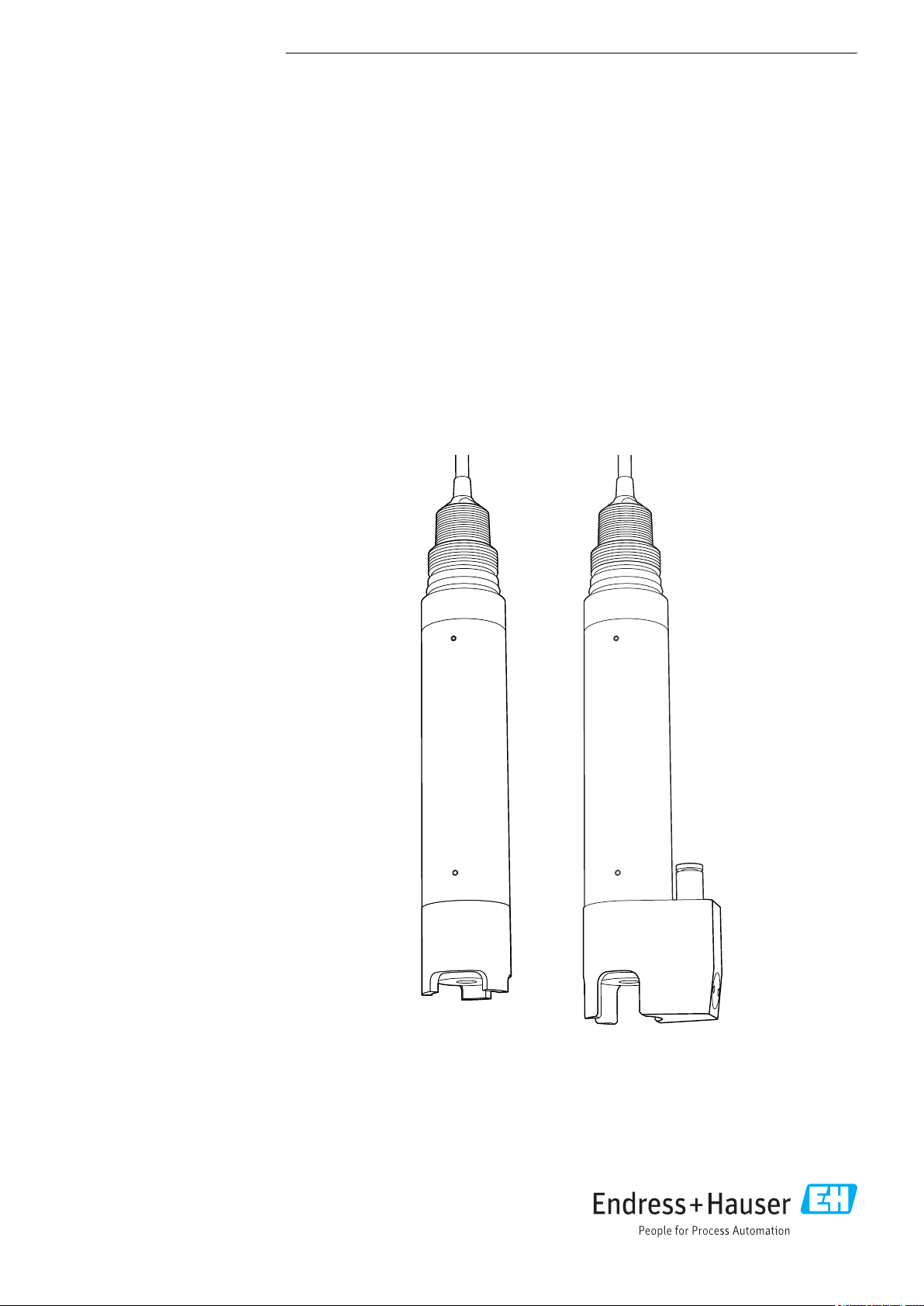
Oxymax COS61D
Sensor for measuring dissolved oxygen
With Memosens protocol
Page 2

Table of contents Oxymax COS61D
Table of contents
1 About this document ................ 3
1.1 Warnings ............................ 3
1.2 Symbols .............................. 3
2 Basic safety instructions ............ 4
2.1 Requirements for personnel ............... 4
2.2 Designated use ........................ 4
2.3 Workplace safety ....................... 4
2.4 Operational safety ...................... 4
2.5 Product safety ......................... 5
3 Device description, function ......... 6
3.1 Optical measuring principle ............... 6
3.2 Sensor design ......................... 7
3.3 Memosens technology ................... 8
3.4 Fluorescence cap ....................... 8
4 Incoming acceptance and product
identification ....................... 9
4.1 Incoming acceptance .................... 9
4.2 Product identification .................... 9
4.3 Scope of delivery ...................... 10
5 Installation ....................... 11
5.1 Installation conditions .................. 11
5.2 Mounting the sensor ................... 12
5.3 Installation examples ................... 15
5.4 Post-installation check .................. 18
6 Electrical connection .............. 19
6.1 Connecting the sensor .................. 19
6.2 Ensuring the degree of protection .......... 19
6.3 Post-connection check .................. 19
10 Maintenance ...................... 25
10.1 Maintenance schedule .................. 25
10.2 Maintenance tasks ..................... 25
10.3 Cleaning exterior of sensor ............... 25
10.4 Cleaning sensor optics .................. 26
10.5 Wear parts and consumables ............. 26
10.6 Checking the measurement function ....... 27
11 Accessories ....................... 28
11.1 Assemblies (selection) .................. 28
11.2 Assembly holder ...................... 28
11.3 Measuring cable ...................... 28
11.4 Zero-point gel ........................ 29
11.5 Protection guard ...................... 29
11.6 Cleaning unit ......................... 29
11.7 Calibration vessel ...................... 29
12 Repair ............................ 30
12.1 Spare parts and consumables ............. 30
12.2 Return .............................. 30
12.3 Disposal ............................ 30
13 Technical data .................... 31
13.1 Input ............................... 31
13.2 Performance characteristics .............. 31
13.3 Environment ......................... 31
13.4 Process ............................. 32
13.5 Mechanical construction ................ 32
Index .................................. 34
7 Calibration and adjustment ........ 20
7.1 Types of calibration .................... 20
7.2 Calibration intervals .................... 20
7.3 Calibration in air ...................... 20
7.4 Calculation example for the calibration
value ............................... 21
8 Commissioning .................... 23
8.1 Function check ....................... 23
8.2 Sensor calibration ..................... 23
8.3 Cleaning the sensor automatically ......... 23
9 Troubleshooting .................. 24
9.1 Troubleshooting instructions ............. 24
9.2 Checking the sensor .................... 24
2 Endress+Hauser
Page 3

Oxymax COS61D About this document
1 About this document
1.1 Warnings
Structure of information Meaning
DANGER
L
Causes (/consequences)
If necessary, Consequences of
non-compliance (if applicable)
Corrective action
‣
WARNING
L
Causes (/consequences)
If necessary, Consequences of
non-compliance (if applicable)
Corrective action
‣
CAUTION
L
Causes (/consequences)
If necessary, Consequences of
non-compliance (if applicable)
Corrective action
‣
NOTICE
Cause/situation
If necessary, Consequences of
non-compliance (if applicable)
Action/note
‣
This symbol alerts you to a dangerous situation.
Failure to avoid the dangerous situation will result in a fatal or serious
injury.
This symbol alerts you to a dangerous situation.
Failure to avoid the dangerous situation can result in a fatal or serious
injury.
This symbol alerts you to a dangerous situation.
Failure to avoid this situation can result in minor or more serious injuries.
This symbol alerts you to situations which may result in damage to
property.
1.2 Symbols
Symbol Meaning
Additional information, tips
Permitted or recommended
Not permitted or not recommended
Reference to device documentation
Reference to page
Reference to graphic
Result of a step
Endress+Hauser 3
Page 4

Basic safety instructions Oxymax COS61D
2 Basic safety instructions
2.1 Requirements for personnel
• Installation, commissioning, operation and maintenance of the measuring system may
be carried out only by specially trained technical personnel.
• The technical personnel must be authorized by the plant operator to carry out the
specified activities.
• The electrical connection may be performed only by an electrical technician.
• The technical personnel must have read and understood these Operating Instructions
and must follow the instructions contained therein.
• Faults at the measuring point may only be rectified by authorized and specially trained
personnel.
Repairs not described in the Operating Instructions provided must be carried out only
directly at the manufacturer's site or by the service organization.
2.2 Designated use
The oxygen sensor is suitable for continuous measurement of dissolved oxygen in water.
The main areas of application are:
• Wastewater treatment plants
– Oxygen measurement and regulation in the activated sludge basin for a highly
efficient biological cleaning process
– Monitoring the oxygen content in the wastewater treatment plant outlet
• Water monitoring
Oxygen measurement in rivers, lakes or seas as an indicator of the water quality
• Water treatment
Oxygen measurement for status monitoring, e.g. of drinking water (oxygen enrichment,
corrosion protection etc.)
• Fish farming
Oxygen measurement and regulation for optimum living and growth conditions
Use of the device for any purpose other than that described, poses a threat to the safety of
people and of the entire measuring system and is therefore not permitted.
The manufacturer is not liable for damage caused by improper or non-designated use.
2.3 Workplace safety
As the user, you are responsible for complying with the following safety conditions:
• Installation guidelines
• Local standards and regulations
Electromagnetic compatibility
• The product has been tested for electromagnetic compatibility in accordance with the
applicable European standards for industrial applications.
• The electromagnetic compatibility indicated applies only to a product that has been
connected in accordance with these Operating Instructions.
2.4 Operational safety
Before commissioning the entire measuring point:
1. Verify that all connections are correct.
2. Ensure that electrical cables and hose connections are undamaged.
4 Endress+Hauser
Page 5

Oxymax COS61D Basic safety instructions
3. Do not operate damaged products, and protect them against unintentional operation.
4. Label damaged products as defective.
During operation:
If faults cannot be rectified:
‣
products must be taken out of service and protected against unintentional operation.
CAUTION
L
Cleaning not switched off during calibration or maintenance activities
Risk of injury due to medium or cleaning agent!
If a cleaning system is connected, switch it off before removing a sensor from the
‣
medium.
If you wish to check the cleaning function and have therefore not switched off the
‣
cleaning system, wear protective clothing, goggles and gloves or take other appropriate
measures.
2.5 Product safety
The product is designed to meet state-of-the-art safety requirements, has been tested, and
left the factory in a condition in which it is safe to operate. The relevant regulations and
European standards have been observed.
Endress+Hauser 5
Page 6

Device description, function Oxymax COS61D
3 Device description, function
3.1 Optical measuring principle
Sensor structure
Oxygen-sensitive molecules (markers) are integrated into an optically active layer
(fluorescence layer).
The fluorescence layer, an optical insulating layer and a cover layer are applied on top of
one another on a carrier. The cover layer is in direct contact with the medium.
The sensor optics are directed at the rear of the carrier and therefore at the fluorescence
layer.
Measurement process (principle of quenching)
If the sensor is immersed in the medium, an equilibrium is very quickly established
between the oxygen partial pressure in both the medium and the fluorescence layer.
1. The sensor optics send green light pulses to the fluorescence layer.
2. The markers "respond" (fluoresce) with red light pulses.
The duration and intensity of the response signals are directly dependent on the
oxygen contents and oxygen partial pressure.
If the medium is free from oxygen, the response signals are long and very intense.
Oxygen molecules mask the marker molecules. As a result, the response signals are
shorter and less intense.
Measurement result
The sensor returns a signal that is proportional to the oxygen concentration in the
‣
medium.
The medium temperature and air pressure are already taken into account to calculate the
oxygen concentration in the sensor.
The sensor provides measured values for temperature and partial pressure as well as a raw
measured value. This value corresponds to the fluorescence decay time and is approx.
20 μs in air and approx. 60 μs in oxygen-free media.
For optimum measurement results
1. During calibration, enter the current air pressure at the transmitter.
2. In the case of saline media:
Enter the salinity.
3. For measurements in the units %Vol or %SAT:
Also enter the current operating pressure in the measuring mode.
Operating Instructions for Memosens, BA01245C
For all transmitters, analyzers and samplers in the Liquiline CM44x/P/R, Liquiline
System CA80XX and Liquistation CSFxx product families
6 Endress+Hauser
Page 7
Oxymax COS61D Device description, function
1
2
3
4
5
6
7
8
3.2 Sensor design
A0037096
1 Sensor structure
1 Sensor cable 5 Threaded connection
2 Sensor shaft 6 Detector
3 O-ring 7 Emitter diode
4 Protection guard 8 Fluorescence cap
The sensor consists of the following function units:
• Sensor shaft
• Sensor head with optics (emitter and detector)
• Protection guard
• Fluorescence cap
As an alternative to the protection guard, you can use a cleaning unit for immersion
operation with cleaning (→ 29).
Endress+Hauser 7
Page 8

Device description, function Oxymax COS61D
3.3 Memosens technology
Sensors with Memosens protocol have an integrated electronics unit that stores calibration
data and other information. Once the sensor has been connected, the sensor data are
transferred automatically to the transmitter and used to calculate the measured value.
Call up the sensor data via the corresponding DIAG menu.
‣
Digital sensors can store measuring system data in the sensor. These include the following:
• Manufacturer data
– Serial number
– Order code
– Date of manufacture
• Calibration data
– Calibration date
– Calibration values
– Number of calibrations
– Serial number of the transmitter used to perform the last calibration
• Operating data
– Temperature application range
– Date of initial commissioning
– Hours of operation under extreme conditions
3.4 Fluorescence cap
The oxygen dissolved in the medium is diffused to the fluorescence layer of the
fluorescence cap. A suitable flow is not required, as no oxygen is consumed during
measurement. However, flow improves the speed at which the measuring system reacts
and ensures a more representative measured value compared to a measurement in a static
medium.
The cap is permeable for dissolved gases only. Other substances dissolved in the liquid
phase, such as ionic substances, will not penetrate through the membrane. Therefore,
medium conductivity has no impact on the measuring signal.
8 Endress+Hauser
Page 9

Oxymax COS61D Incoming acceptance and product identification
4 Incoming acceptance and product
identification
4.1 Incoming acceptance
1. Verify that the packaging is undamaged.
Notify the supplier of any damage to the packaging.
Keep the damaged packaging until the issue has been resolved.
2. Verify that the contents are undamaged.
Notify the supplier of any damage to the delivery contents.
Keep the damaged goods until the issue has been resolved.
3. Check that the delivery is complete and nothing is missing.
Compare the shipping documents with your order.
4. Pack the product for storage and transportation in such a way that it is protected
against impact and moisture.
The original packaging offers the best protection.
Make sure to comply with the permitted ambient conditions.
If you have any questions, please contact your supplier or your local Sales Center.
4.2 Product identification
4.2.1 Nameplate
The nameplate provides you with the following information on your device:
• Manufacturer identification
• Order code
• Extended order code
• Serial number
• Safety information and warnings
Compare the information on the nameplate with the order.
‣
4.2.2 Product identification
Product page
www.endress.com/cos61d
Interpreting the order code
The order code and serial number of your product can be found in the following locations:
• On the nameplate
• In the delivery papers
Obtaining information on the product
1. Go to www.endress.com.
2. Call up the site search (magnifying glass).
3. Enter a valid serial number.
4. Search.
The product structure is displayed in a popup window.
Endress+Hauser 9
Page 10

Incoming acceptance and product identification Oxymax COS61D
5. Click on the product image in the popup window.
A new window (Device Viewer) opens. All of the information relating to your
device is displayed in this window as well as the product documentation.
Manufacturer address
Endress+Hauser Conducta GmbH+Co. KG
Dieselstraße 24
D-70839 Gerlingen
4.3 Scope of delivery
Scope of delivery of sensor
• Oxygen sensor with protection cap or mounted cleaning system (optional)
• Brief Operating Instructions
10 Endress+Hauser
Page 11
Oxymax COS61D Installation
45°
135°
45°
0° 180°
5 Installation
5.1 Installation conditions
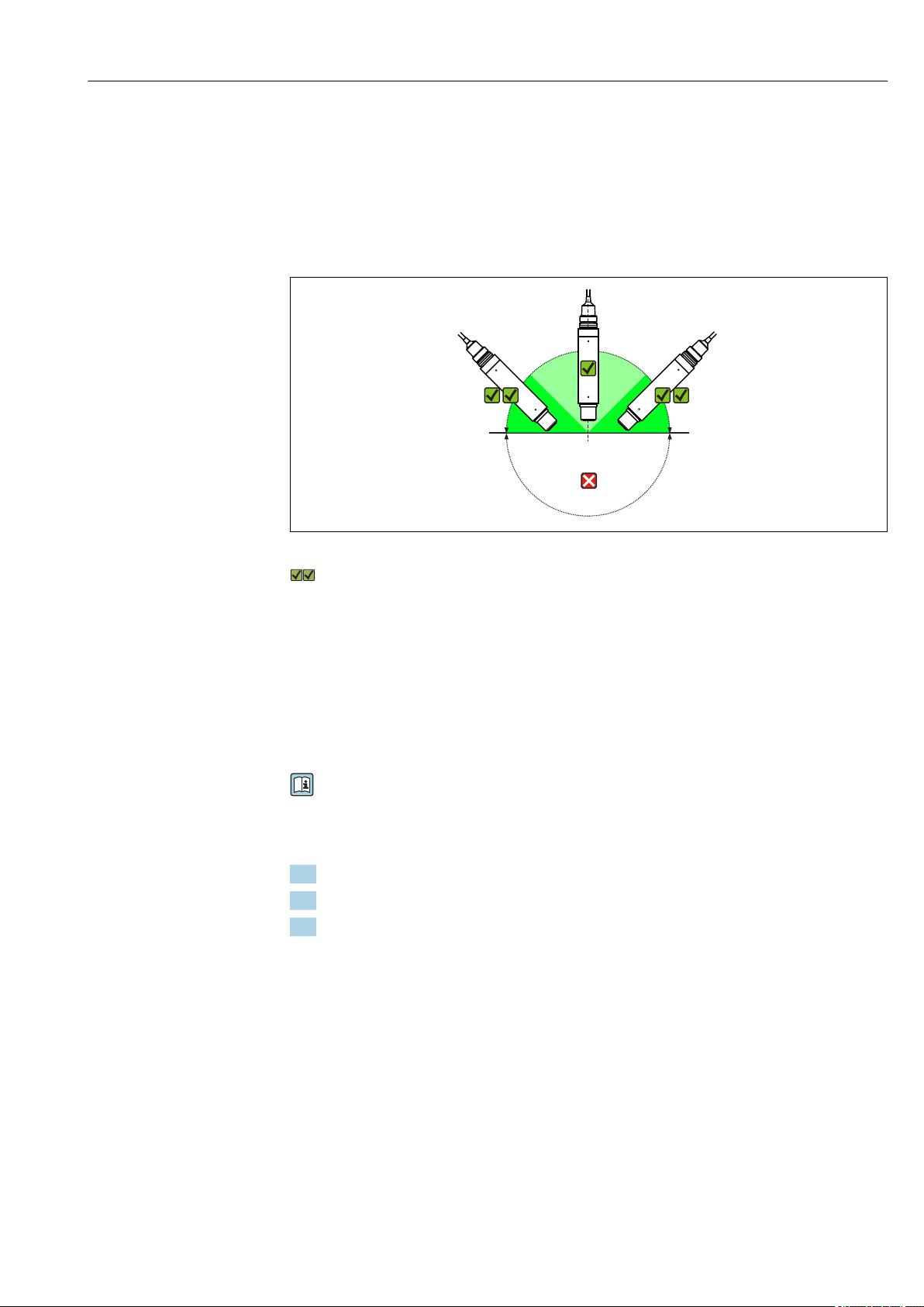
5.1.1 Orientation
A0032281
2 Angle of installation
Recommended angle of inclination
The sensor must be installed at an angle of inclination in an assembly, holder or
appropriate process connection. Recommended angle: 45° to prevent the attachment of air
bubbles. At angles of inclination of 45 to 135°, air bubbles at the oxygen-sensitive
membrane may increase the measured value.
The sensor can be installed up to the horizontal in an assembly, holder or suitable process
connection. The optimum installation angle is 45°.
Other angles and upside-down installation are not recommended. Reason: Possible
sediment formation and resulting falsification of measured value.
Follow the instructions for installing sensors in the Operating Instructions for the
assembly used.
5.1.2 Mounting location
1. Choose a mounting location that is easy to access.
2. Ensure that upright posts and assemblies are fully secured and vibration-free.
3. Choose a mounting location with an oxygen concentration that is typical for the
application.
Endress+Hauser 11
Page 12

Installation Oxymax COS61D
1 2
3
4
5
6
5.2 Mounting the sensor
5.2.1 Measuring system
COS61D
A complete measuring system consists of the following components at least:
• Oxymax COS61D oxygen sensor
• Liquiline CM44x multi-channel transmitter
• Sensor cable, optionally available with M12 connector
• Assembly, e.g. flow assembly COA250, immersion assembly CYA112 or
retractable assembly COA451
Optionally:
• Assembly holder Flexdip CYH112 for immersion operation
• Extension cable CYK11
• Cleaning system
3 Example of a measuring system with COS61D
1
Sensor cable
2
Liquiline CM44x
3
Flexdip CYH112
A0012882
4
Basin rim with railing
5
Oxymax COS61D
6
FlexdipCYA112
12 Endress+Hauser
Page 13

Oxymax COS61D Installation
1
2
5.2.2 Mounting the cleaning unit
If the cleaning unit is not supplied in a preassembled state:
1.
Unscrew protection guard.
Retain the protection guard for possible reuse at a later stage without the
cleaning unit.
2.
Screw on cleaning unit and tighten until the stop.
The cleaning nozzle should now be level with the spot.
1 Cleaning nozzle
2 Spot
3.
Connect the hose for the compressed air supply (to be provided onsite) or
compressor(→ 29) to the hose connection of the cleaning unit.
5.2.3 Installing at a measuring point
Must be installed in a suitable assembly (depending on the application).
Endress+Hauser 13
Page 14

Installation Oxymax COS61D
WARNING
L
Electrical voltage
In the event of a fault, non-grounded metallic assemblies may be live and as such are not
safe to touch!
When using metallic assemblies and installation equipment, national grounding
‣
provisions must be observed.
• For immersion operation, install individual assemblies away from the basin on a
solid base.
• Final assembly must be performed only at the assigned mounting location.
• Choose a mounting location that is easy to access.
For complete installation of a measuring point, proceed as follows:
1. Install a retractable or a flow assembly (if used) into the process.
2. Connect the water supply to the rinse connections (if you are using an assembly with
a cleaning function).
3. Install and connect the oxygen sensor.
NOTICE
Installation error
Cable breakage, loss of sensor due to cable separation, unscrewing of fluorescence cap!
Do not install the sensor freely suspended from the cable.
‣
Screw the sensor into the assembly, ensuring that the cable is not twisted.
‣
Hold on to the sensor body during installation or removal. Turn only at the hexagonal
‣
nut of the armored coupling. Otherwise you might unscrew the fluorescence cap. This
will then remain in the assembly or process.
Avoid exerting excessive tensile force on the cable (e.g. through jerky pulling
‣
movements).
Choose a mounting location that is easy to access for later calibrations.
‣
Follow the instructions for installing sensors in the Operating Instructions for the
‣
assembly used.
14 Endress+Hauser
Page 15

Oxymax COS61D Installation
1
5
2
4
3
1 2
3
6
4
5
5.3 Installation examples
5.3.1 Immersion operation
Universal holder and chain assembly
4 Chain holder on railing
1 Chain
2 Holder Flexdip CYH112
3 Rail
4 Sensor Oxymax
5 Wastewater assembly Flexdip CYA112
A0030564
A0030565
5 Chain holder on upright post
1 Weather protection cover CYY101
2 Controller / transmitter
3 Chain
4 Wastewater assembly Flexdip CYA112
5 Sensor Oxymax
6 Holder Flexdip CYH112
Endress+Hauser 15
Page 16

Installation Oxymax COS61D
1
2
3
4
5
2
3
4
Universal holder and fixed immersion tube
A0030567
6 Assembly holder with immersion tube
1 Protective cover
2 Controller / transmitter
3 Flexdip CYA112 immersion assembly
4 Sensor Oxymax
5 Assembly holder Flexdip CYH112
Basin rim mounting with immersion tube
A0030568
7 Basin rim mounting
1 Pendulum holder CYH112
2 Assembly Flexdip CYA112
3 Assembly float
4 Sensor Oxymax
16 Endress+Hauser
Page 17

Oxymax COS61D Installation
1
2
3
4
5
6
7
G1
800 (31.50)
500 (19.69)
220 (8.66)
Ø200 (7.87)
1
23
4
6
7
8
5
Float
The CYA112 float is for use in the case of large fluctuations in water level, for example in
rivers or lakes.
1 Cable run with strain relief and rain shield
2 Fixing ring for rope and chains with terminal screw
3 Eyelets Ø15, 3 x 120 ° for anchoring
4 Plastic float, resistant to salt water
5 Pipe 40 x 1, stainless steel 1.4571
6 Bumper and ballast
7 Oxygen sensor
A0032159
8 Dimensions in mm (inch)
5.3.2 Flow assembly COA250
A0013319
9 COA250
10 Bypass installation with manually actuated valves or solenoid
valves
1 Main pipe
2 Medium return
3 Oxygen sensor
4, 7 Manually actuated or solenoid valves
5 Flow assembly COA250-A
6 90 ° pipe elbow
8 Medium removal
A0030570
Endress+Hauser 17
Page 18

Installation Oxymax COS61D
5
3
4
2
3
Detail A
Detail A, 90 ° r
5.3.3 Retractable assembly COA451
A0030571
11 Permissible and impermissible sensor installation positions with retractable assembly COA451
1 Ascending pipe, best position
2 Horizontal pipe, sensor top down, impermissible due to air cushion or foam bubble forming
3 Horizontal pipe, lateral installation with permissible installation angle (acc. to sensor version)
4 Down pipe, impermissible
NOTICE
Sensor not fully immersed in the medium, deposit on sensor membrane or sensor
optics, sensor installed upside down
Incorrect measurements are possible and these may affect the measuring point.
Do not install the assembly at points where air pockets or bubbles form or where
‣
suspended particles may build up at the sensor membrane or sensor optics (item 2).
5.4 Post-installation check
1. Are the sensor and cable undamaged?
2. Is the orientation correct?
3. Is the sensor installed in an assembly and is not suspended from the cable?
4. Avoid the penetration of moisture by fitting the protection cap on the immersion
assembly.
18 Endress+Hauser
Page 19

Oxymax COS61D Electrical connection
GN
PK
GY
YE
COM A
COM B
U
+
U
–
6 Electrical connection
WARNING
L
Device is live!
Incorrect connection may result in injury or death!
The electrical connection may be performed only by an electrical technician.
‣
The electrical technician must have read and understood these Operating Instructions
‣
and must follow the instructions contained therein.
Prior to commencing connection work, ensure that no voltage is present on any cable.
‣
6.1 Connecting the sensor
Connection data
• Sensor cable connected directly to the terminal connector of the basic module
• Optional: sensor cable plug connected to the M12 sensor socket of the transmitter
With this type of connection, the transmitter is already wired at the factory.
12 Sensor fixed cable with terminated cable cores
6.2 Ensuring the degree of protection
Only the mechanical and electrical connections which are described in these instructions
and which are necessary for the required, designated use, may be carried out on the device
delivered.
Exercise care when carrying out the work.
‣
Otherwise, the individual types of protection (Ingress Protection (IP), electrical safety, EMC
interference immunity) agreed for this product can no longer be guaranteed due,
for example to covers being left off or cable (ends) that are loose or insufficiently secured.
6.3 Post-connection check
Device condition and specifications Notes
Are the sensor, assembly, or cables free from damage on the
outside?
Electrical connection Notes
Are the mounted cables strain-relieved and not twisted?
Is a sufficient length of the cable cores stripped, and are the cores
positioned in the terminal correctly?
Are all the screw terminals properly tightened? Tighten
Are all cable entries mounted, tightened and leak-tight? For lateral cable entries, make sure the
Are all cable entries installed downwards or mounted laterally?
Visual inspection
Check the fit (by pulling gently)
cables loop downwards to allow water to
drip off
Endress+Hauser 19
Page 20

Calibration and adjustment Oxymax COS61D
7 Calibration and adjustment
7.1 Types of calibration
The following types of calibration are possible:
• Zero point
– Single-point calibration in nitrogen or COY8 zero-point gel
– Data entry
• Slope
– Air, water vapor-saturated
– Air-saturated water
– Air, variable
– Data entry
• Sample calibration
Slope
• Temperature adjustment
7.2 Calibration intervals
Specifying the intervals
If you want to calibrate the sensor intermittently for a special application and/or on
account of a special type of installation, you can calculate the intervals using the following
method:
1. Remove the sensor from the medium.
2. Clean the outside of the sensor with a damp cloth.
3. Then dry the sensor diaphragm carefully with a soft paper towel for example.
4. NOTICE
Incorrect measurements caused by atmospheric influences!
Protect the sensor against external influences such as sunlight and wind.
‣
After 10 minutes, measure the oxygen saturation index in air.
5. Decide using the results:
a) Measured value is not 100 ± 2 %SAT → Calibrate sensor.
b) If the values are within the interval specified, you do not need to calibrate the sensor.
Extend the period until the next inspection.
6. Repeat the steps specified after two, four or eight months to determine the optimum
calibration interval for your sensor.
In any case, calibrate the sensor at least once a year.
‣
7.3 Calibration in air
1. Remove the sensor from the medium.
2. Clean the outside of the sensor with a damp cloth.
3. Allow a temperature compensation time of approx. 20 minutes for the sensor in the
ambient air. Make sure that the sensor is not exposed to any direct ambient effects
(direct sunlight, drafts) during this time.
20 Endress+Hauser
Page 21

Oxymax COS61D Calibration and adjustment
4. Is the measured value display on the transmitter stable:
Perform the calibration in accordance with the Operating Instructions for the
transmitter. Pay particular attention to the software settings for the stability criteria
for calibration and for the ambient pressure.
5. Where necessary:
Adjust sensor.
6. Then place the sensor back into the medium.
Follow the calibration instructions in the Operating Instructions for the transmitter
‣
used.
7.4 Calculation example for the calibration value
As a check, you can calculate the expected calibration value (transmitter display) as shown
in the following example (salinity is 0).
1. Determine the following:
• The ambient temperature for the sensor (air temperature for Air 100% rh or calibration
methods Air variable, water temperature for H2O air-saturatedcalibration method)
• The altitude above sea level
• The current air pressure (= relative air pressure based on sea level) at the time of
calibration. (If undeterminable, use 1013 hPa.)
2. Determine the following:
• The saturation value S acc. to Table 1
• The altitude factor K acc. to Table 2
Table 1
T
[˚C (˚F)]S[mg/l=ppm]T[˚C (˚F)]S[mg/l=ppm]T[˚C (˚F)]S[mg/l=ppm]T[˚C (˚F)]S[mg/l=ppm]
0 (32) 14.64 11 (52) 10.99 21 (70) 8.90 31 (88) 7.42
1 (34) 14.23 12 (54) 10.75 22 (72) 8.73 32 (90) 7.30
2 (36) 13.83 13 (55) 10.51 23 (73) 8.57 33 (91) 7.18
3 (37) 13.45 14 (57) 10.28 24 (75) 8.41 34 (93) 7.06
4 (39) 13.09 15 (59) 10.06 25 (77) 8.25 35 (95) 6.94
5 (41) 12.75 16 (61) 9.85 26 (79) 8.11 36 (97) 6.83
6 (43) 12.42 17 (63) 9.64 27 (81) 7.96 37 (99) 6.72
7 (45) 12.11 18 (64) 9.45 28 (82) 7.82 38 (100) 6.61
8 (46) 11.81 19 (66) 9.26 29 (84) 7.69 39 (102) 6.51
9 (48) 11.53 20 (68) 9.08 30 (86) 7.55 40 (104) 6.41
10 (50) 11.25
Table 2
Altitude
[m (ft)]
0 (0) 1.000 550 (1800) 0.938 1050 (3450) 0.885 1550 (5090) 0.834
50 (160) 0.994 600 (1980) 0.932 1100 (3610) 0.879 1600 (5250) 0.830
100 (330) 0.988 650 (2130) 0.927 1150 (3770) 0.874 1650 (5410) 0.825
150 (490) 0.982 700 (2300) 0.922 1200 (3940) 0.869 1700 (5580) 0.820
K Altitude
[m (ft)]
K Altitude
[m (ft)]
K Altitude
[m (ft)]
K
Endress+Hauser 21
Page 22

Calibration and adjustment Oxymax COS61D
Altitude
[m (ft)]
200 (660) 0.977 750 (2460) 0.916 1250 (4100) 0.864 1750 (5740) 0.815
250 (820) 0.971 800 (2620) 0.911 1300 (4270) 0.859 1800 (5910) 0.810
300 (980) 0.966 850 (2790) 0.905 1350 (4430) 0.854 1850 (6070) 0.805
350 (1150) 0.960 900 (2950) 0.900 1400 (4600) 0.849 1900 (6230) 0.801
400 (1320) 0.954 950 (3120) 0.895 1450 (4760) 0.844 1950 (6400) 0.796
450 (1480) 0.949 1000 (3300) 0.890 1500 (4920) 0.839 2000 (6560) 0.792
500 (1650) 0.943
K Altitude
[m (ft)]
K Altitude
[m (ft)]
K Altitude
[m (ft)]
3. Calculate factor L:
Relative air pressure at calibration
L= -----------------------------------------------
1013 hPa
4. Calculate calibration value C:
C = S . K . L
Example
• Air calibration at 18 °C (64 °F), altitude 500 m (1650 ft) above sea level, current air
pressure 1009 hPa
• S = 9.45 mg/l, K = 0.943, L = 0.996
• Calibration value C = 8.88 mg/l.
You do not need factor K in the table if your measuring device returns the absolute air
pressure L
for calculation is then: C = S . L
(air pressure depending on altitude) as the measured value. The formula
abs
.
abs
K
22 Endress+Hauser
Page 23

Oxymax COS61D Commissioning
8 Commissioning
8.1 Function check
Prior to initial commissioning, ensure that:
• The sensor is correctly installed
• The electrical connection is correct
If using an assembly with automatic cleaning function:
Check that the cleaning medium (water or air, for example) is connected correctly.
‣
WARNING
L
Escaping process medium
Risk of injury from high pressure, high temperatures or chemical hazards!
Before applying pressure to an assembly with cleaning system, ensure that the system
‣
has been connected correctly.
If you cannot reliably establish the correct connection, do not install the assembly in
‣
the process.
Following commissioning, the sensor must be serviced at regular intervals, as only
then can reliable measurement be guaranteed.
Operating Instructions for the transmitter used, such as BA01245C if using the
Liquiline CM44x or CM44xR.
8.2 Sensor calibration
The sensor is calibrated at the factory. A new calibration is only needed in special
situations.
8.3 Cleaning the sensor automatically
Compressed air is most suitable for cyclic cleaning. The cleaning unit is either provided or
can be retrofitted, and is attached to the sensor head. It operates at a capacity of 20-60 l/
min. Optimum results are achieved at 2 bar (29 psi) and 60 l/min.
The following settings are recommended for the cleaning unit:
Type of soiling Cleaning interval Cleaning duration
Media containing grease and oils 15 min 20 s
Biofilm 60 min 20 s
Endress+Hauser 23
Page 24

Troubleshooting Oxymax COS61D
9 Troubleshooting
9.1 Troubleshooting instructions
If one of the following problems is present:
‣
Check the measuring system in the order shown.
Problem Testing Remedial action
Nothing displayed, no reaction
from the sensor
Displayed value too high Is sensor calibrated/adjusted?
Displayed value too low Is sensor calibrated/adjusted?
Display in Vol% or %SAT not
plausible.
Power supply to the transmitter?
Sensor cable connected correctly?
Deposit buildup on fluorescence
layer?
Displayed temperature clearly too
low?
Has salinity been taken into
account?
Displayed temperature clearly too
high?
Deposit buildup on the
fluorescence layer?
Medium pressure has not been
taken into account.
Connect power supply.
‣
Establish correct connection.
‣
Clean sensor.
‣
Recalibrate/readjust.
‣
During calibration, enter the
current air pressure at the
transmitter.
Check sensor, if necessary send sensor
‣
in for repair.
Enter salinity value on transmitter.
‣
Recalibrate/readjust.
‣
Check sensor, if necessary send sensor
‣
in for repair.
Clean sensor.
‣
Enter medium pressure on
‣
transmitter.
1. Pay attention to the troubleshooting information in the Operating Instructions for
the transmitter.
2. Check the transmitter if necessary.
9.2 Checking the sensor
Testing Corrective action Set point
Slope check
Zero-point check
1. In the case of deviations from the set points:
Perform troubleshooting as indicated in the troubleshooting instructions.
2. Contact the Sales Center if necessary.
Place the sensor in air.
‣
Dry the sensor with a paper towel.
‣
Immerse the sensor in zero-point gel
‣
(→ 29).
Measured value display after 1 minute:
Approx. 100 % SAT
Display close to 0 mg/l (0 % SAT)
24 Endress+Hauser
Page 25

Oxymax COS61D Maintenance
10 Maintenance
Take all the necessary precautions in time to ensure the operational safety and reliability
of the entire measuring system.
NOTICE
Effects on process and process control!
When carrying out any work on the system, bear in mind any potential impact this
‣
could have on the process control system and the process itself.
For your own safety, only use genuine accessories. With genuine parts, the function,
‣
accuracy and reliability are also ensured after maintenance work.
10.1 Maintenance schedule
Maintenance cycles depend to a great extent on the operating conditions.
The following rule of thumb applies:
• Constant conditions, e.g. Power plant = long cycles (1/2 year)
• Widely varying conditions, e.g. daily CIP or SIP cleaning = short cycles (1 month or
shorter)
The following method helps you determine the necessary intervals:
1. Inspect the sensor one month after commissioning. To do so, remove the sensor from
the medium and dry it.
2. After 10 minutes, measure the oxygen saturation index in air.
Decide using the results:
a) Measured value not 100 ±2 %SAT? → Service the sensor.
b) Measured value = 100 ±2 %SAT? → Double the length of time to the next
inspection.
3. Proceed as indicated in Step 1 after two, four and eight months.
This allows you to determine the optimum maintenance interval for your sensor.
Particularly in the case of widely fluctuating process conditions, damage may occur to
the fluorescence layer even within a maintenance cycle. You can recognize this by
implausible sensor behavior. (→ 24)
10.2 Maintenance tasks
The following tasks are mandatory:
1. Clean the sensor fluorescence cap . → 25
2. Replace wear parts or consumables. → 26
3. Check measurement function. → 27
4. Recalibrate (if desired or necessary).
Follow the Operating Instructions for the transmitter.
10.3 Cleaning exterior of sensor
The measurement can be corrupted by sensor fouling or malfunction due to the following,
for example:
Deposit buildup on the fluorescence cap
This results in a longer response time and, under certain circumstances, a reduced
slope.
For reliable measurement, the sensor must be cleaned at regular intervals. The frequency
and intensity of the cleaning operation depend on the medium.
Endress+Hauser 25
Page 26

Maintenance Oxymax COS61D
Clean the sensor:
• Before every calibration
• At regular intervals during operation as necessary
• Before returning it for repairs
Type of contamination Cleaning
Salt deposits 1. Immerse the sensor in drinking water or in 1-5 % hydrochloric
acid (for a few minutes).
2. Then rinse it with copious amounts of water.
Dirt particles on the sensor shaft and
shaft sleeve (not fluorescence cap!)
Dirt particles on fluoresence cap
After cleaning:
‣
Clean sensor shaft and sleeve with water and a suitable sponge.
‣
Clean the fluorescence cap with water and a soft cloth.
‣
Rinse with copious amounts of clean water.
10.4 Cleaning sensor optics
The optics need to be cleaned only if medium has penetrated a defective fluorescence cap.
1. Unscrew the protection guard and fluorescence cap from the sensor head.
2. Carefully clean the optical surface with a soft cloth until the buildup is fully removed.
3. Clean the optical surface with drinking water or distilled water.
4. Dry the optical surface and screw on a functional fluorescence cap.
5. At the transmitter, execute the command Sensor cap change and then perform the
necessary calibrations.
NOTICE
Damage, scratches on optical surface
Distorted measured values
Make sure that the optical surface is not scratched or damaged in any other way.
‣
10.5 Wear parts and consumables
Parts of the sensor are subject to wear during operation. By taking suitable measures, you
can restore the normal operating function.
Corrective action Reason
Replace process seals Visible damage to a process seal
Replace fluorescence cap Fluorescence layer can no longer be cleaned or is damaged (hole or overstretching)
10.5.1 Replacing sealing rings
It is compulsory to replace the sealing ring if it is visibly damaged. For replacement, use
only original sealing rings.
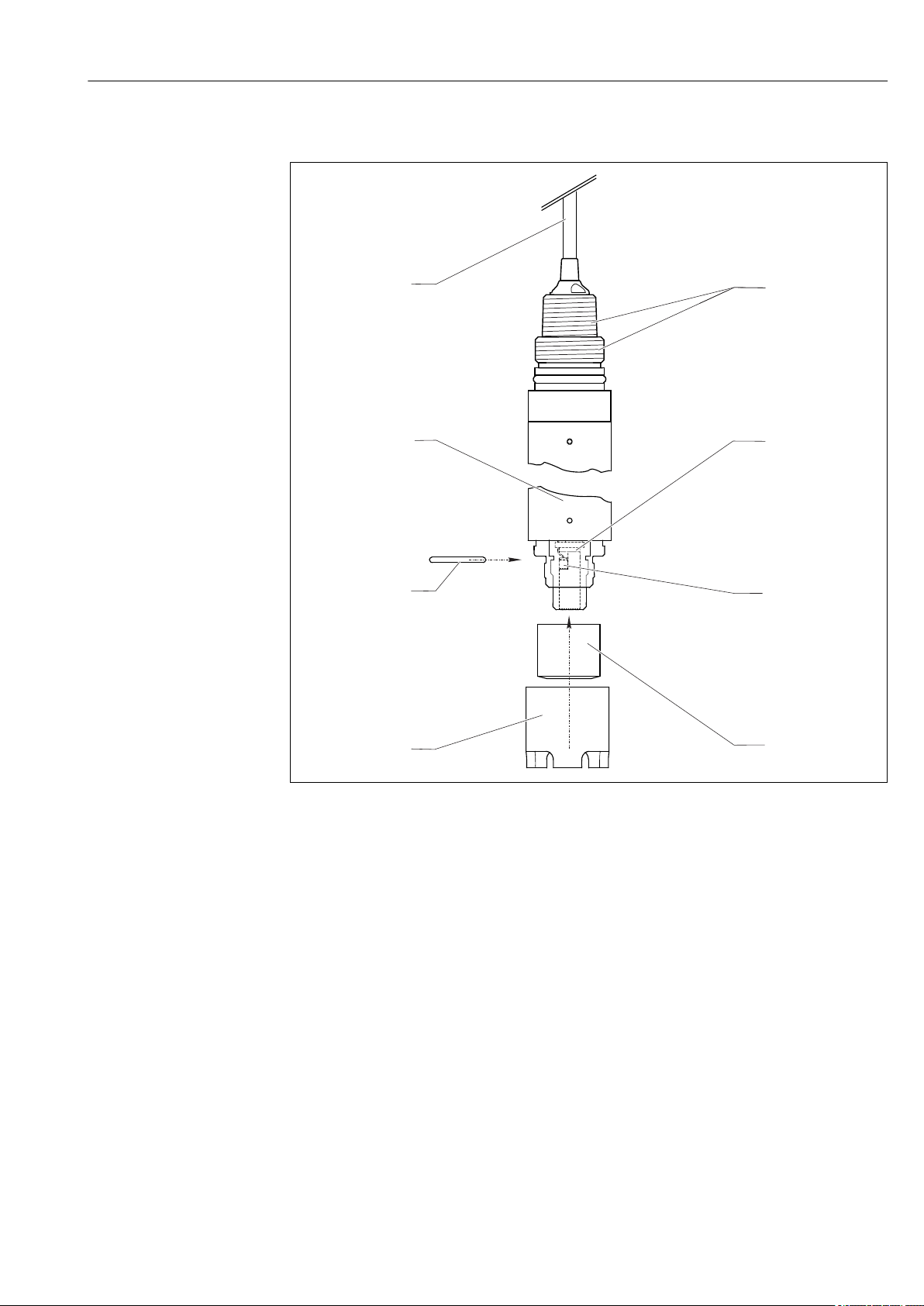
10.5.2 Replacing the fluorescence cap
The typical operating life of a fluorescence cap is more than 2 years. The sensor checks
whether the cap is aging and issues a warning via the transmitter if the rate of aging
reaches a specific value. The sensor is still able to measure at this stage. However, it is
advisable to change the cap as quickly as possible.
26 Endress+Hauser
Page 27

Oxymax COS61D Maintenance
Removing the old fluorescence cap
1. Remove the sensor from the medium.
2. Unscrew protection guard.
3. Clean exterior of sensor.
4. Unscrew fluorescence cap.
5. Clean and dry optical surface.
Installing the new fluorescence cap
Make sure that there are no dirt particles on the sealing surfaces.
6. Carefully screw the new fluorescence cap onto the sensor head and tighten until the
stop.
7. Screw protection guard back on.
After replacing the fluorescence cap, you must recalibrate and adjust the sensor.
8. Then place the sensor back into the medium and check that no alarm is displayed on
the transmitter.
10.6 Checking the measurement function
1. Remove the sensor from the medium.
2. Clean and dry the fluorescence cap.
3. After about 10 minutes, measure the oxygen saturation index in air (without
recalibration).
The measured value should be at 100 ± 2 % SAT.
Endress+Hauser 27
Page 28

Accessories Oxymax COS61D
11 Accessories
The following are the most important accessories available at the time this documentation
was issued.
For accessories not listed here, please contact your Service or Sales Center.
‣
11.1 Assemblies (selection)
FlexdipCYA112
• Immersion assembly for water and wastewater
• Modular assembly system for sensors in open basins, channels and tanks
• Material: PVC or stainless steel
• Product Configurator on the product page: www.endress.com/cya112
Technical Information TI00432C
Flowfit COA250
• Flow assembly for oxygen measurement
• Product Configurator on the product page: www.endress.com/coa250
Technical Information TI00111C
Cleanfit COA451
• Manual retractable assembly made of stainless steel with ball valve shutoff
• For oxygen sensors
• Product Configurator on the product page: www.endress.com/coa451
Technical Information TI00368C
11.2 Assembly holder
Flexdip CYH112
• Modular holder system for sensors and assemblies in open basins, channels and tanks
• For Flexdip CYA112 water and wastewater assemblies
• Can be affixed anywhere: on the ground, on the capstone, on the wall or directly onto
railings.
• Stainless steel version
• Product Configurator on the product page: www.endress.com/cyh112
Technical Information TI00430C
11.3 Measuring cable
Memosens data cable CYK11
• Extension cable for digital sensors with Memosens protocol
• Product Configurator on the product page: www.endress.com/cyk11
Technical Information TI00118C
28 Endress+Hauser
Page 29

Oxymax COS61D Accessories
11.4 Zero-point gel
COY8
Zero-point gel for oxygen and chlorine sensors
• Oxygen-free gel for the validation, calibration and adjustment of oxygen measuring cells
• Product Configurator on the product page: www.endress.com/coy8
Technical Information TI01244C
11.5 Protection guard
Membrane basket protector COY3-SK
• For using the sensor in fish farming tanks
• Order No.: 50081787
11.6 Cleaning unit
Compressed air cleaning for COSXX
• Connection: AD 6/8 mm (incl. hose reducer coupling) or AD 6.35 mm (¼")
• Materials: POM/V4A
• Order No.
– AD 6/8 mm: 71110801
– AD 6.35 mm (¼"): 71110802
Compressor
• For compressed air cleaning
• Order No.
– 230 V AC order no. 71072583
– 115 V AC order no. 71194623
11.7 Calibration vessel
Calibration vessel
• For COS61D/61
• Order No.: 51518599
Endress+Hauser 29
Page 30

Repair Oxymax COS61D
1
2
3
4
12 Repair
12.1 Spare parts and consumables
Item Spare parts kit Order number
1 Sensor As per product structure
2 Sealing ring x 2 51518597
3 Sensor cap (fluorescence cap) 51518598
4 Protection guard 50053276
12.2 Return
The product must be returned if repairs or a factory calibration are required, or if the
wrong product was ordered or delivered. As an ISO-certified company and also due to legal
regulations, Endress+Hauser is obliged to follow certain procedures when handling any
returned products that have been in contact with medium.
To ensure the swift, safe and professional return of the device:
Refer to the website www.endress.com/support/return-material for information on the
‣
procedure and conditions for returning devices.
12.3 Disposal
The device contains electronic components. and must therefore be disposed of in
accordance with regulations on the disposal of electronic waste.
Observe the local regulations.
‣
30 Endress+Hauser
Page 31

Oxymax COS61D Technical data
13 Technical data
13.1 Input
Measured variables Dissolved oxygen [mg/l, µg/l, ppm, ppb or %SAT or hPa]
Measuring ranges Measuring ranges apply for 25 ˚C (77 ˚F) and 1013 hPa (15 psi)
With Liquiline CM44x, CM44xR, CM44P:
• 0 to 20 mg/l
• 0 to 400 hPa
• 0 to 200 % SAT
13.2 Performance characteristics
Response time From air to nitrogen at reference operating conditions:
t90 : 60 s
Reference operating conditions
Maximum measured
1)
error
Repeatability ±0.5 % of end of measuring range
Operating life of sensor cap >2 years (under reference operating conditions, protect against direct sunlight)
Reference temperature: 25 °C (77 °F)
Reference pressure: 1013 hPa (15 psi)
Reference application: Air-saturated water
Measuring range Maximum measured error
< 12 mg/l 0.01 mg/l or ±1 % of reading
12 mg/l to 20 mg/l ±2% of reading
13.3 Environment
Ambient temperature –20 to 60 °C (–4 to 140 °F)
Storage temperature –20 to 70 °C (–4 to 158 °F)
at 95% relative air humidity, not condensating
Degree of protection IP 68 (test conditions: 10 m (33 ft) water column, at 25 °C (77 °F) over 30 days)
Electromagnetic compatibility
1) In accordance with IEC 60746-1 at rated operating conditions
Endress+Hauser 31
Interference emission and interference immunity as per EN 61326: 2005, Namur NE
21:2007
Page 32

Technical data Oxymax COS61D
232.5 (9.15)
Ø40 (1.57)
186 (7.32)
12 (0.47)
77 (3.04) / 66 (2.59)*
197 (7.76)
243.5 (9.59)
21 (0.83)
15 (0.59)
11 (0.43)
46.5 (1.83)
NPT ¾"
G1
13.4 Process
Process temperature –5 to +60 ˚C (20 to 140 ˚F)
Process pressure Ambient pressure ... 10 bar (... 145 psi) abs.
13.5 Mechanical construction
Dimensions
13 With optional M12 connector
Dimensions in mm (inch)
A0037103
14 With optional cleaning unit
* depending on version of cleaning unit
A0037093
32 Endress+Hauser
Page 33

Oxymax COS61D Technical data
50 (1.97)
19 (0.75)
19 (0.75)
Ø40 (1.57)
24°
61 (2.40)
28.5 (1.12)
A
B
77 (3.04)
11 (0.43)
Optional cleaning unit
A0013314
15 Dimensions in mm (inch)
Weight with cable length 7 m (23 ft): 0.7 kg (1.5 lbs)
with cable length 15 m (49 ft): 1.1 kg (2.4 lbs)
Materials Parts in contact with medium
Sensor shaft Stainless steel 1.4435 (AISI 316L)
Cap with fluorescence layer POM
Fluorescence layer Silicone
Process connection G1, NPT 3/4"
Sensor cable Shielded 4-core fixed cable
Cable connection at transmitter
• Terminal connection, end ferrules
• Optional: M12 connector
Maximum cable length max. 100 m (330 ft), incl. Cable extension
Temperature compensation Internal
Interface Memosens protocol
Endress+Hauser 33
Page 34

Index Oxymax COS61D
Index
A
Accessories ................................ 28
Adjustment ................................20
Ambient temperature ........................ 31
Assemblies ................................ 28
C
Calibration
Calculation example ....................... 21
In air .................................. 20
Types of calibration ....................... 20
Check
Connection ..............................19
Function ............................... 23
Installation ............................. 18
Cleaning
Sensor ................................. 25
Sensor optics ............................ 26
Cleaning sensor optics ........................ 26
Cleaning unit .............................. 13
Connection
Check ..................................19
Ensuring the degree of protection ............. 19
D
Degree of protection
Degree of protection .......................31
Ensuring ............................... 19
Designated use .............................. 4
Device description ............................ 6
Dimensions ................................32
Disposal .................................. 30
E
Electrical connection ......................... 19
Environment ...............................31
F
Fluorescence cap ............................. 8
Replacement ............................ 26
Function ................................... 6
Function check ............................. 23
I
Incoming acceptance ......................... 9
Installation
Check ..................................18
Cleaning unit ............................ 13
Examples ............................... 15
Orientation ............................. 11
Sensor ................................. 12
Installation instructions .......................11
M
Maintenance schedule ........................25
Maintenance tasks .......................... 25
Manufacturer address ........................ 10
Materials ................................. 33
Maximum measured error ..................... 31
Measured variables .......................... 31
Measurement function ....................... 27
Measuring cable ............................ 28
Measuring point ............................ 13
Measuring principle ...........................6
Measuring ranges ........................... 31
Measuring system ........................... 12
N
Nameplate ................................. 9
O
Operating life of sensor cap .................... 31
Operational safety ............................4
Optical measuring principle ..................... 6
Orientation ................................ 11
P
Performance characteristics ....................31
Process ................................... 32
Process connection .......................... 33
Process pressure ............................ 32
Process temperature ......................... 32
Product identification ......................... 9
Product safety ............................... 5
R
Reference operating conditions ................. 31
Repair ....................................30
Repeatability ...............................31
Replacing sealing rings ....................... 26
Response time ..............................31
Return ................................... 30
S
Safety
Operation ................................4
Product ................................. 5
Workplace safety .......................... 4
Safety instructions ............................4
Scope of delivery ............................ 10
Sensor
Calibration ..............................23
Check ..................................24
Cleaning .............................23, 25
Connecting ..............................19
Design .................................. 7
Mounting ...............................12
Sensor design ............................... 7
Spare parts ................................ 30
Spot cap .................................. 26
Storage temperature ......................... 31
Symbols ................................... 3
34 Endress+Hauser
Page 35

Oxymax COS61D Index
T
Technical data
Environment ............................ 31
Input .................................. 31
Mechanical construction ....................32
Performance characteristics ................. 31
Process ................................ 32
Troubleshooting ............................ 24
Troubleshooting instructions ................... 24
U
Use .......................................4
W
Warnings .................................. 3
Wear parts and consumables ................... 26
Weight ................................... 33
Workplace safety ............................ 4
Z
Zero-point gel .............................. 29
Endress+Hauser 35
Page 36

*71411043*
71411043
www.addresses.endress.com
 Loading...