

Page 1
Operating Instructions
Oxymax COS51D
Digital sensor for dissolved oxygen
With Memosens technology
BA00413C/07/EN/13.12
71153927
Page 2
Documentation information
DANGER
!
WARNING
!
CAUTION
!
NOTICE
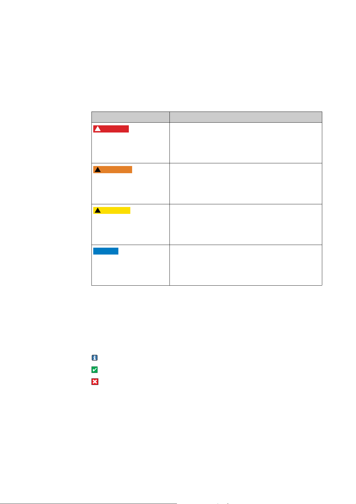
Warnings
The structure, signal words and safety colors of the signs comply with the specifications of
ANSI Z535.6 ("Product safety information in product manuals, instructions and other collateral
materials").
Safety message structure Meaning
This symbol alerts you to a dangerous situation.
Cause (/consequences)
Consequences if safety message
is not heeded
► Corrective action
Cause (/consequences)
Consequences if safety message
is not heeded
► Corrective action
Cause (/consequences)
Consequences if safety message
is not heeded
► Corrective action
Failure to avoid the situation will result in a fatal or serious
injury.
This symbol alerts you to a dangerous situation.
Failure to avoid the situation can result in a fatal or serious
injury.
This symbol alerts you to a dangerous situation.
Failure to avoid this situation can result in minor or medium
injury.
This symbol alerts you to situations that can result in damage to
Cause/situation
Consequences if safety message
is not heeded
► Action/note
property and equipment.
Symbols used
1 This symbol indicates a cross reference to a defined page (e.g. p. 1).
È ä
2 This symbol indicates a cross reference to a defined figure (e.g. fig. 2).
È å
Additional information, tips
Permitted or recommended
Forbidden or not recommended
Endress+Hauser
Page 3

Oxymax COS51D
Table of contents
1 Basic safety instructions . . . . . . . . . . . . 4
1.1 Requirements for personnel . . . . . . . . . . . . . . . . . . . 4
1.2 Designated use . . . . . . . . . . . . . . . . . . . . . . . . . . . . 4
1.3 Occupational safety . . . . . . . . . . . . . . . . . . . . . . . . . 4
1.4 Operational safety . . . . . . . . . . . . . . . . . . . . . . . . . . 4
1.5 Product safety . . . . . . . . . . . . . . . . . . . . . . . . . . . . . 5
1.6 Special safety instructions COS51D-G*8*0* . . . . . . 5
2 Identification . . . . . . . . . . . . . . . . . . . . 6
2.1 Product page and configurator . . . . . . . . . . . . . . . . . 6
2.2 Order code . . . . . . . . . . . . . . . . . . . . . . . . . . . . . . . 6
2.3 Scope of delivery . . . . . . . . . . . . . . . . . . . . . . . . . . . 6
2.4 Certificates and approvals . . . . . . . . . . . . . . . . . . . . 7
3 Installation . . . . . . . . . . . . . . . . . . . . . . 8
3.1 Incoming acceptance, transport, storage . . . . . . . . . . 8
3.2 Installation conditions . . . . . . . . . . . . . . . . . . . . . . . 8
3.3 Installation instructions . . . . . . . . . . . . . . . . . . . . . . 9
3.4 Installation examples . . . . . . . . . . . . . . . . . . . . . . . 11
3.5 Post-installation check . . . . . . . . . . . . . . . . . . . . . . 15
4 Wiring . . . . . . . . . . . . . . . . . . . . . . . . 16
9 Trouble-shooting . . . . . . . . . . . . . . . . . 31
9.1 Trouble-shooting instructions . . . . . . . . . . . . . . . . . 31
9.2 Sensor checks . . . . . . . . . . . . . . . . . . . . . . . . . . . . 32
9.3 Spare parts . . . . . . . . . . . . . . . . . . . . . . . . . . . . . . . 33
9.4 Return . . . . . . . . . . . . . . . . . . . . . . . . . . . . . . . . . . 33
9.5 Disposal . . . . . . . . . . . . . . . . . . . . . . . . . . . . . . . . . 33
10 Technical data . . . . . . . . . . . . . . . . . . . 34
10.1 Input . . . . . . . . . . . . . . . . . . . . . . . . . . . . . . . . . . . 34
10.2 Performance characteristics . . . . . . . . . . . . . . . . . . 34
10.3 Environment . . . . . . . . . . . . . . . . . . . . . . . . . . . . . 35
10.4 Process . . . . . . . . . . . . . . . . . . . . . . . . . . . . . . . . . 35
10.5 Mechanical construction . . . . . . . . . . . . . . . . . . . . 35
11 EC Declaration of Conformity . . . . . . . 36
Index . . . . . . . . . . . . . . . . . . . . . . . . . . 37
4.1 Quick wiring guide . . . . . . . . . . . . . . . . . . . . . . . . 16
4.2 Temperature ranges . . . . . . . . . . . . . . . . . . . . . . . . 16
4.3 Direct connection to the transmitter . . . . . . . . . . . 17
4.4 Post-connection check . . . . . . . . . . . . . . . . . . . . . . 17
5 Device description . . . . . . . . . . . . . . . 18
5.1 Sensor design . . . . . . . . . . . . . . . . . . . . . . . . . . . . 18
5.2 Measuring principle . . . . . . . . . . . . . . . . . . . . . . . . 19
5.3 Calibration . . . . . . . . . . . . . . . . . . . . . . . . . . . . . . 20
6 Commissioning. . . . . . . . . . . . . . . . . . 24
6.1 Function check . . . . . . . . . . . . . . . . . . . . . . . . . . . 24
6.2 Polarization . . . . . . . . . . . . . . . . . . . . . . . . . . . . . . 24
6.3 Calibration . . . . . . . . . . . . . . . . . . . . . . . . . . . . . . 24
6.4 Automatic cleaning . . . . . . . . . . . . . . . . . . . . . . . . 25
7 Maintenance. . . . . . . . . . . . . . . . . . . . 26
7.1 Cleaning . . . . . . . . . . . . . . . . . . . . . . . . . . . . . . . . 26
7.2 Replacing wear and tear materials . . . . . . . . . . . . . 27
8 Accessories. . . . . . . . . . . . . . . . . . . . . 29
8.1 Connection accessories . . . . . . . . . . . . . . . . . . . . . 29
8.2 Installation accessories . . . . . . . . . . . . . . . . . . . . . . 29
8.3 Cleaning . . . . . . . . . . . . . . . . . . . . . . . . . . . . . . . . 30
Endress+Hauser 3
Page 4

Basic safety instructions Oxymax COS51D
1 Basic safety instructions
1.1 Requirements for personnel
► Installation, commissioning, operation and maintenance of the measuring system must only be
carried out by trained technical personnel.
► The technical personnel must be authorized by the plant operator to carry out the specified
activities.
► The electrical connection may only be performed by an electrical technician.
► The technical personnel must have read and understood these Operating Instructions and must
follow the instructions they contain.
► Measuring point faults may only be rectified by authorized and specially trained personnel.
Repairs not described in the enclosed Operating Instructions may only be carried out directly
at the manufacturer's or by the service organization.
1.2 Designated use
The oxygen sensor is suitable for continuous measurement of dissolved oxygen in water.
Typical applications are:
• Measuring, monitoring and regulating the oxygen content in activated sludge basins.
• Monitoring the oxygen content in the sewage treatment plant outlet.
• Monitoring, measuring and regulating the oxygen content in public waters and fish farming
water.
• Monitoring of oxygen enrichment in drinking water.
Any other use than the one described here compromises the safety of persons and the entire
measuring system and is not permitted.
The manufacturer is not liable for damage caused by improper or non-designated use.
1.3 Occupational safety
As the user, you are responsible for complying with the following safety conditions:
• Regulations for explosion protection
• Installation instructions
• Local standards and regulations
Electromagnetic compatibility
With regard to electromagnetic compatibility, this device has been tested in accordance with the
applicable European standards for industrial applications.
The electromagnetic compatibility indicated only applies to a device that has been connected in
accordance with the instructions in these Operating Instructions.
1.4 Operational safety
► Before commissioning the entire measuring point, make sure all the connections are correct.
Ensure that electrical cables and hose connections are not damaged.
► Do not operate damaged products, and safeguard them to ensure that they are not operated
inadvertently. Mark the damaged product as defective.
► If faults cannot be rectified, the products must be taken out of service and secured against
unintentional commissioning.
4 Endress+Hauser
Page 5

Oxymax COS51D Basic safety instructions
CAUTION
!
The cleaning system is not switched off during calibration or maintenance activities
Risk of injury due to medium or cleaning agent
► If a cleaning system is connected, switch it off before removing a sensor from the medium.
► If you are not switching off the cleaning system because you wish to test the cleaning function,
wear protective clothing, goggles and gloves or take other appropriate measures.
1.5 Product safety
The product is designed to meet state-of-the-art safety requirements, has been tested and left the
factory in a condition in which it is safe to operate. Relevant regulations and European standards
have been observed.
1.6 Special safety instructions COS51D-G*8*0*
• The certified oxygen sensor Oxymax COS51D-G*8*0* may only be connected via the measuring
cable CYK10-G**1 to approved intrinsically safe digital sensor circuits of the transmitter Liquiline
M CM42-*G*. The electrical connection instruction must be followed.
• The measuring cable CYK10-G and its coupling must be protected from electrostatic charging, if
installed through zone 0.
• The sensor may not be operated under process conditions where electrostatic charging is likely to
occur. The designated use in media with a conductivity of at least 10 nS/cm can be assumed as
electrostatic uncritical.
• Ex versions of digital sensors with Memosens technology are indicated by an orange-red ring on
the plug-in head.
• The maximum permissible cable length is 100 m (330 ft).
Endress+Hauser 5
Page 6
Identification Oxymax COS51D
2 Identification
2.1 Product page and configurator
You can create a complete and valid order code by using the configurator on the internet product
page.
Product page link:
www.products.endress.com/cos51d
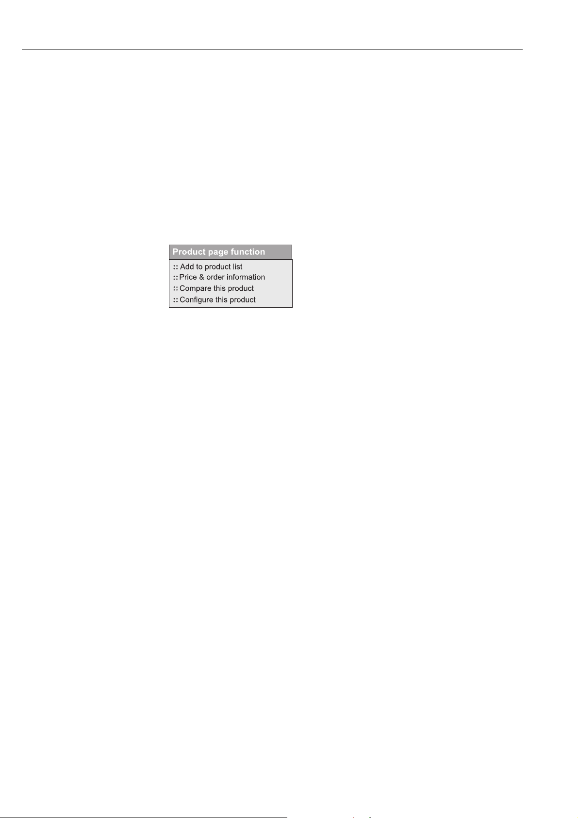
2.2 Order code
1. You can choose from the following options on the product page located on the right:
2. Click "Configure this product".
3. The configurator opens in a separate window.
Use the radio buttons to configure the order code from the nameplate of your device.
4. Afterwards, you can export the order code as a PDF or Excel file.
To do so, click the appropriate button at the top of the page.
2.3 Scope of delivery
The following items are included in the delivery:
• Oxygen sensor with transport protection cap for membrane protection
• Accessories set with the following contents:
– 2 replacement cartridges (replacement membrane caps)
– 10 plastic ampoules containing electrolyte
– 1 sealing kit with 3 O-rings
– 6 abrasive sheets
• Operating Instructions (on CD only)
• Brief Operating Instructions (paper version)
If you have any questions, please contact your supplier or your local sales center.
6 Endress+Hauser
Page 7

Oxymax COS51D Identification
2.4 Certificates and approvals
2.4.1 ATEX II 1G/IECEx Ex ia IIC T6 Ga
The inductive sensor-cable-plug-in system Memosens consisting of:
• oxygen sensor Oxymax W COS51D-G*8*0 and
• measuring cable CYK10-G**1
is suitable for the use in explosion-hazardous locations acc. to the type-examination certificate BVS
04 ATEX E 121 X . The corresponding EC declaration of conformity is part of this document.
2.4.2 FM/CSA
Version COS51D-O****
IS Class 1 Division 1 ABCD T4/T6
Class 1 Zone 0 AEx ia IIC T4/T6
2.4.3 Notified body
DEKRA EXAM GmbH
Bochum (Germany)
Endress+Hauser 7
Page 8
Installation Oxymax COS51D
3 Installation
3.1 Incoming acceptance, transport, storage
► Make sure the packaging is undamaged!
► Inform the supplier about any damage to the packaging.
Keep the damaged packaging until the matter has been settled.
► Make sure the contents are undamaged!
► Inform the supplier about damage to the contents. Keep the damaged products until the matter
has been settled.
► Check that the order is complete and agrees with your shipping documents.
► The packaging material used to store or to transport the product must provide shock protection
and humidity protection. The original packaging offers the best protection. Also, keep to the
approved ambient conditions (see "Technical data").
► If you have any questions, please contact your supplier or your local sales center.
3.2 Installation conditions
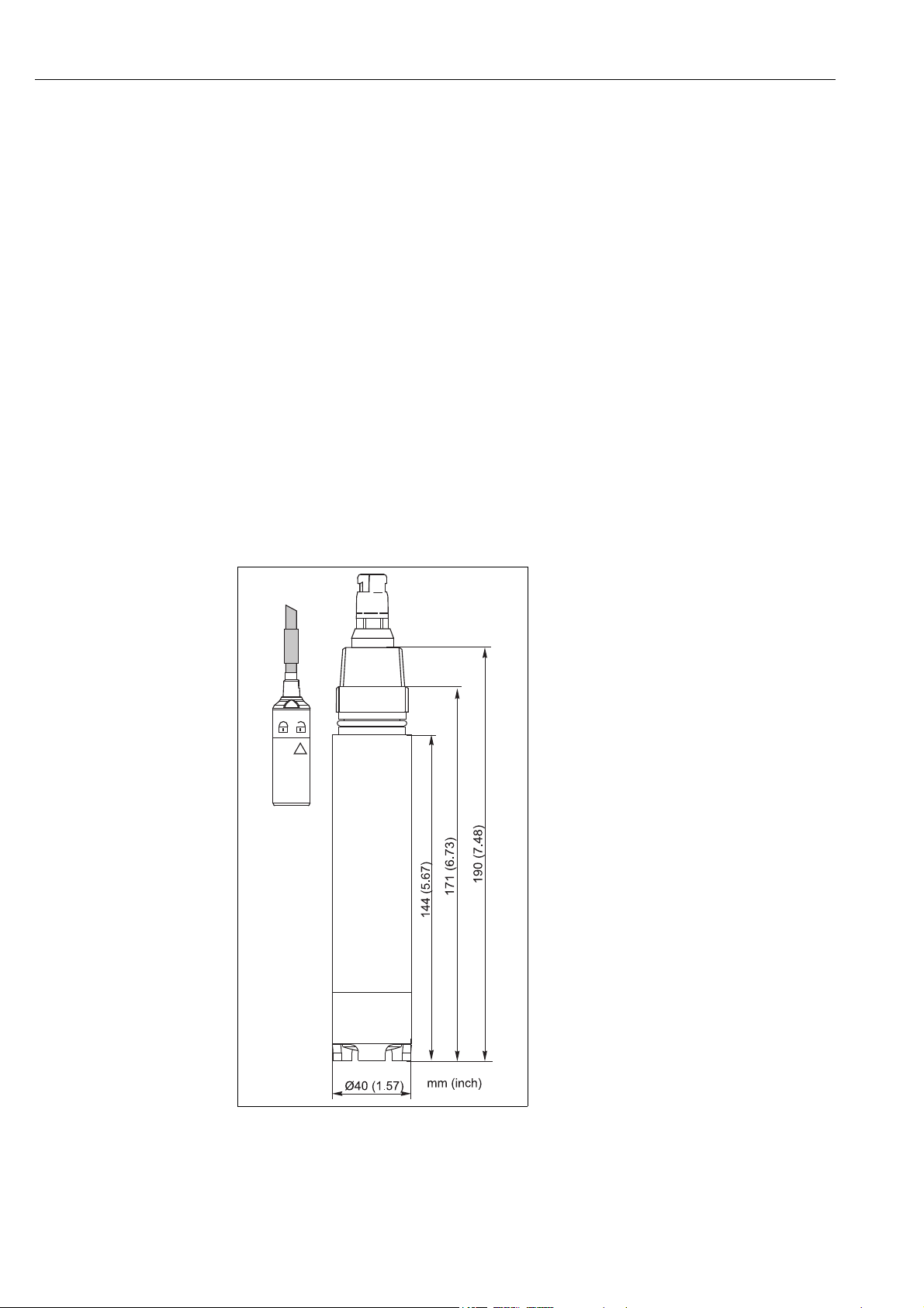
3.2.1 Dimensions
a0006742
Fig. 1: Dimensions
8 Endress+Hauser
Page 9
Oxymax COS51D Installation
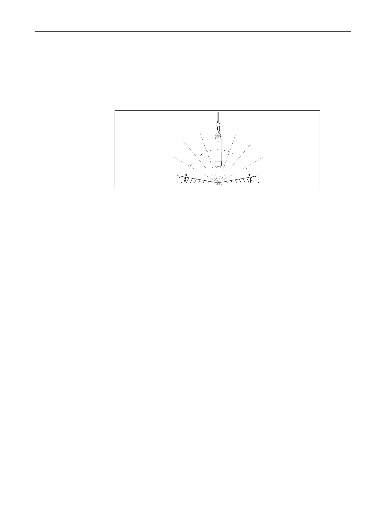
10° 10°
Not permissible!
Not permissible!
Permissible angle of installation
3.2.2 Angle of installation
The sensor must be installed with an angle of inclination of at least 10 ˚ to the horizontal in an
assembly, support or a suitable process connection. Other angles are not permissible. Do not install
the sensor overhead.
► Make sure you comply with the instructions for installing sensors. You will find them in the
Operating Instructions for the assembly used.
a0006741-en
Fig. 2: Permissible angle of installation
3.2.3 Mounting location
• Select the installation location so that there is easy access for later calibration.
• Make sure that upright posts and assemblies are secured safely and vibration-free.
• Select an installation location which produces a typical oxygen concentration.
3.3 Installation instructions
3.3.1 Measuring system
A complete measuring system comprises at least:
• the digital oxygen sensor Oxymax COS51D
• a transmitter, e.g. Liquiline CM42
• a special measuring cable, CYK10
• an assembly, e.g. immersion assembly CYA112 or retractable assembly COA451
Optional (see accessories):
•Holder system CYH112 for immersion operation
• Automatic cleaning system Chemoclean with spray head
Endress+Hauser 9
Page 10
Installation Oxymax COS51D
NOTICE
a0006735
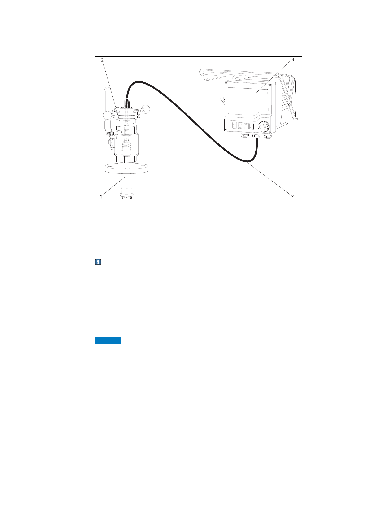
Fig. 3: Measuring system (example)
1 Digital oxygen sensor Oxymax W COS51D
2 Retractable assembly COA451
3 Liquiline M CM42
4 Measuring cable CYK10
3.3.2 Installing a measuring point
For immersed operation, install the individual modules away from the basin on a solid base.
Only carry out the final installation at the intended installation location.
For a complete installation of a measuring point, proceed as follows:
1. Install a retractable or a flow assembly (if used) into the process.
2. Connect the water supply to the rinse connections (if you use an assembly with cleaning
function).
3. Install and connect the oxygen sensor.
4. Install an immersion or an suspension assembly (if used) into the process.
No assembly used, sensor not correctly installed, grounding regulations not observed
Risk of damaging the sensor cable, no protection to electromagnetic interferencies
► For immersed operation, the sensor must be installed in an immersion assembly (e.g. CYA611).
Do not install the sensor suspended from the cable.
► Screw the sensor into the assembly so that the cable is not twisted.
► Avoid exerting excessive tensile force on the cable (e.g. from jerky pulling).
► When using metallic assemblies and installation equipment, comply with national grounding
regulations.
► Observe the sensor installation instructions of the Operating Instructions of the assembly used.
10 Endress+Hauser
Page 11
Oxymax COS51D Installation
3.4 Installation examples
3.4.1 Immersion operation
Upright post and chain assembly
For large basins, where sufficient installation distance is required from the basin edge (aeration
basin, especially), it is advisable to use the upright post and chain assembly. The free swinging of
the immersed assembly practically rules out vibrations from the upright post.
According to this effect, the sensor life time can be extended.
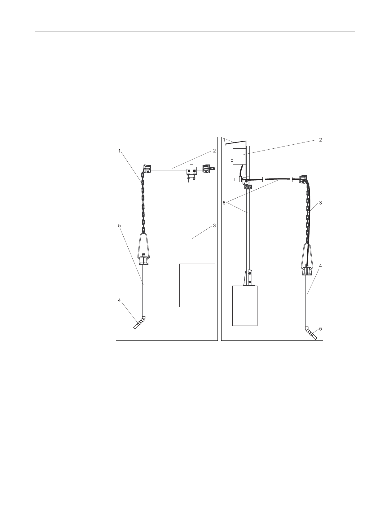
Fig. 4: Chain holder, rail mounted
1Chain
2 Flexdip CYH112 holder
3Rail
4Oxymax sensor
5 Flexdip CYA112 wastewater assembly
a0013510
Fig. 5: Chain holder, mounted to a post
1 Weather protection cover
2 Liquiline CM44x controller
3Chain
4 Flexdip CYA112 wastewater assembly
5Oxymax sensor
6 Flexdip CYH112 holder
a0013511
Endress+Hauser 11
Page 12
Installation Oxymax COS51D
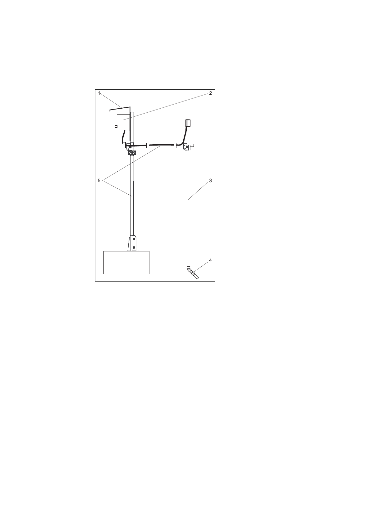
Upright post and fixed immersion assembly
The preferable type of installation for strong or turbulent flow (> 0.5 m/s) in the basin or open
channels is to secure the device to an upright post and a securely mounted immersion tube. If the
flow is very strong, a second transverse pipe can be installed with its own pipe support.
Fig. 6: Assembly holder with immersion tube
1 Weather protection cover CYY101
2 Controller Liquiline CM44x
3 Immersion assembly Flexdip CYA112
4Oxymax sensor
5 Assembly holder Flexdip CYH112
a0013513
12 Endress+Hauser
Page 13

Oxymax COS51D Installation
12
3
4
1
2
3
4
5
6
7
G1
800/31.50
500/19.69
220/8.66
Ø200/7.87
mm/inch
Basin rim mounting with immersion assembly
For fixing to the sides of the basin or channel, we recommend the pendulum holder of the
immersion tube. Optionally, you can also use the assembly with a float.
a0013693
Fig. 7: Basin rim mounting
1 Pendulum holder CYH112
2 Assembly Flexdip CYA112
3 Float of assembly CYA112
4Oxymax sensor
Floating body
To aid installation in strongly fluctuating water levels, e.g. in rivers or lakes, there is a floating body
COA 110-50 available (→ å 8).
Cable route with strain relief and rain protection
1
Mounting ring for ropes and chains with locking
2
screw
Lugs Ø15, 3 x 120 ˚ for anchoring
3
Saltwater-resistant plastic float
4
Pipe 40x1, stainless steel 1.4571 (AISI 316Ti)
5
Shock absorber and weight
6
Oxygen sensor
7
Fig. 8: Floating body
a0004108-en
Endress+Hauser 13
Page 14

Installation Oxymax COS51D
1
23
4
6
7
8
5
3.4.2 Flow assembly
The COA250 flow assembly with automatic self-venting is suitable for use in pipelines or hose
connections. The inlet is at the bottom of the assembly, the outlet at the top (connection thread
G¾). It can be installed in a pipe by using two 90˚ pipe brackets to allow inflow to the assembly
(→ å 10, Pos. 6).
a0004114
Fig. 9: Flow assembly COA250
1 Screw-in part for sensor
2Screw ring
3 Meter body
4 Connection thread G¾
5 Dummy plug (connection for spray head CUR3)
a0004113-en
Fig. 10: Bypass installation with manually
1 Main line
2 Medium return
3 Oxygen sensor
4, 7 Manually actuated or solenoid valves
5 Flow assembly COA250
690 ˚ pipe bracket
8Medium removal
actuated valves or solenoid valves
3.4.3 Retractable assembly
The assembly is designed for installation on tanks and pipes. Suitable nozzles must be available for
this.
Install the assembly at places with constant flow. The minimum pipe diameter is DN 80 (3").
a0004117-en
Fig. 11: Permissible and impermissible sensor installation positions
1 Ascending pipe, best position
2 Horizontal pipe, sensor top down, impermissible due to air cushion or foam bubble forming
3 Horizontal pipe, installation with permissible emitting angles (acc. to sensor version)
4 Overhead installation, impermissible due to missing electrolyte contact of the sensor electrodes
5 Down pipe, impermissible
14 Endress+Hauser
Page 15

Oxymax COS51D Installation
NOTICE
Sensor not immersed into the medium, suspended particles settled on the sensor
membrane or sensor optics, sensor installed overhead
Measuring errors can occur
► Do not install the assembly at places, where air cushions or foam bubbles can be formed or
where suspended particles can settle on the sensor membrane or optics (→ å 11).
3.5 Post-installation check
► Sensor and cable undamaged?
► Compliance with permissible sensor installation position?
► Is the sensor installed in an assembly and is not suspended from the cable?
► Avoid moisture by rain by putting the protective cap on the assembly?
Endress+Hauser 15
Page 16

Wiring Oxymax COS51D
WARNING
!
4 Wiring
Device is energized
Improper connection can cause injury or death.
► The electrical connection must only be carried out by a certified electrician.
► Technical personnel must have read and understood the instructions in this manual and must
adhere to them.
► Prior to beginning any wiring work, make sure voltage is not applied to any of the cables.
4.1 Quick wiring guide
a0010056
Fig. 12: Connection in hazardous locations
4.2 Temperature ranges
If the ambient temperatures indicated are observed, no temperatures which are impermissible for
the temperature class in question will occur at the sensor.
Temperature class
T6
Ambient temperature T
a
16 Endress+Hauser
–5 to +50 ˚C
Page 17

Oxymax COS51D Wiring
4.3 Direct connection to the transmitter
The sensor is connected to the transmitter via the measuring cable CYK10.
a0003350
Fig. 13: Measuring cable CYK10
4.4 Post-connection check
Instrument status and specifications Remarks
Are the sensor, assembly, junction box or cable damaged? Visual inspection
Electrical connection Remarks
Does the supply voltage of the transmitter match the specifications on the
nameplate?
Are the installed cables strain-relieved and not twisted ?
Is the cable type route completely isolated ? Power cable/weak current cable
Are the power supply and signal cable correctly connected to the
transmitter ?
Long enough length of cable core stripped and correct in terminal? Check seating (pull slightly)
Are all the screws terminals properly tightened ? Tighten
Are all the cable entries installed, tightened and sealed ? For cable entries lateral: cable loops
Are all the cable entries installed downwards or lateral ?
Use the connection diagram of the
transmitter.
downwards for water to be able to drip off.
Endress+Hauser 17
Page 18

Device description Oxymax COS51D
1
3
4
5
6
7
8
9
2
10
11
12
13
14
7
8
9
10
6
5 Device description
5.1 Sensor design
a0004149
Fig. 15: Sensor head, cutaway drawing
7Membrane
8 Electrolyte
9Anode
10 Reference electrode
11 Threaded connection for protection basket
12 Sealing ring
13 Threaded connection for membrane cap
14 Membrane cap
a0006935
Fig. 14: Sensor design
1 Memosens Plug-in head
2 Threaded connection NPT ¾"
3 Threaded connection G1
4 Sensor shaft
5Protection basket
6 Gold cathode
7Membrane
8 Electrolyte
9Anode
Fig. 16: Sensor head, top view
6Cathode
a0004150
The sensor consists of the following function units:
•Sensor shaft
•Protection basket
Observe the following
• Alternatively to the protection basket, you can use a spray head COR 3 (optional, see
"Accessories") for use in immersed operation with cleaning function.
• The membrane cap screwed onto the sensor head is filled with electrolyte. The screw connection
seals it from the medium.
• The membrane which is in contact with the medium is pretensioned in the factory.
18 Endress+Hauser
Page 19

Oxymax COS51D Device description
5.2 Measuring principle
5.2.1 Polarization
When the sensor is connected to the transmitter, a fixed external voltage is applied between the
cathode and anode. The resulting polarization current is indicated on the display of the transmitter.
The current starts high but then drops over time. The sensor can only be calibrated when the display
is stable.
5.2.2 Membrane
The oxygen dissolved in the medium is conveyed to the membrane by the incoming flow. The
membrane is only permeable for dissolved gases. Other substances dissolved in the liquid phase e.g.
ionic substances, will not penetrate through the membrane. Therefore, medium conductivity has
no impact on the measuring signal.
5.2.3 Amperometric principle
The oxygen molecules diffused through the membrane are reduced to hydroxide ions (OH-) at the
cathode. Silver is oxidized to silver ions (Ag+) at the anode (this forms a silver halogenide layer).
A current flows due to the electron donation at the cathode and the electron acceptance at the
anode. Under constant conditions, this flow is proportional to the oxygen content of the medium.
This current is converted in the transmitter and indicated on the display as an oxygen concentration
in mg/l, μg/l, ppm, ppb or Vol%, as a saturation index in % SAT or as an oxygen partial pressure in
hPa.
5.2.4 Potentiostatic three-electrode-system
The high-impedance, current-free reference electrode plays an important role.
The formation of a silver bromide or silver chloride coating on the anode uses up the bromide or
chloride ions dissolved in the electrolyte
In the case of conventional membrane-covered sensors working with the two-electrode system, this
causes an increase in signal drift.
This is not the case with the three-electrode system:
The change in bromide or chloride concentration is registered by the reference electrode and an
internal control circuit holds the working electrode potential constant. The advantages of this
principle are significantly increased accuracy of the signal and considerably extended calibration
intervals.
Endress+Hauser 19
Page 20

Device description Oxymax COS51D
5.2.5 Memosens technology
The sensor is connected to the cable connection (CYK10) without contact. The power and data are
transferred inductively
Once connected to the transmitter, the data saved in the sensor are read digitally. You can call up
these data using the corresponding DIAG menu.
Data that digital sensors save include the following:
• Manufacturer data
– Serial number
–Order code
– Date of manufacture
• Calibration data
– Calibration date
– Calibration values
– Number of calibrations
– Serial number of the transmitter used to perform the last calibration
• Operational data
– Date of commissioning
– Hours of operation under extreme conditions
– Data for sensor monitoring.
5.3 Calibration
Calibration is a means of adapting the transmitter to the characteristic values of the sensor.
As normally no zero calibration is required for the sensor, a single-point calibration is carried out in
the presence of oxygen.
Normally, sensor calibration is seldom necessary. It is necessary after:
• First commissioning
• Replacing a membrane or electrolyte
• Cleaning the cathode
• Long breaks in operation without power supply
Within the framework of system monitoring and supervision, for example, the calibration can also
be cyclically monitored (at typical time intervals, depending on operating experience) or renewed.
5.3.1 Types of calibration
You can carry out single-point or two-point calibration for the sensor.
In most applications, single-point calibration suffices in the presence of oxygen (=calibration of
measured value at air).
The additional calibration of the zero point (two-point calibration) improves the precision of the
measurement results in the trace range. Calibrate the zero point with nitrogen (minimum 99.995%)
or with water free from oxygen, for example. In doing so, make sure the measured value has settled
correctly (20 to 30 minutes) to avoid incorrect measurements in the trace range at a later stage.
The available types of calibration depend on the transmitter used. Refer to your transmitter's
Operating Instructions to find out which types of calibration are supported.
20 Endress+Hauser
Page 21

Oxymax COS51D Device description
Types of calibration:
• Slope:
– Air (saturated with water vapor, e.g. near the water surface)
– Air-saturated water
– Variable air (entering the current relative humidity and the absolute air pressure)
– Data entry
• Zero point:
– Zero point calibration (nitrogen or water free from oxygen)
– Data entry
• Reference:
– Grab sample calibration
– Offset
– Slope
5.3.2 Calibration intervals
The calibration intervals depend heavily on:
• The application and
• The installation position of the sensor.
You can determine the intervals with the following method:
1. Check the sensor one month after its being put into operation:
– Remove the sensor from the medium.
– Clean the outside of the sensor with a damp cloth.
– Then dry the sensor membrane e.g. by using a tissue.
– Measure the oxygen saturation index at air after 20 minutes.
2. Decide using the results:
a. If the measured value is not at 102 ±2 %SAT, you have to calibrate the sensor.
b. Otherwise, lengthen the time to the next inspection.
3. Proceed as per Point 1 after two, four and/or eight months. In this way, you can determine
the optimum calibration interval for your sensor.
Be sure to calibrate the sensor at least once a year.
5.3.3 Calibration in air
1. Remove the sensor from the medium.
2. Clean the outside of the sensor with a damp cloth.
Then dry the sensor membrane e.g. by using a tissue.
3. Then wait while the sensor adjusts to the temperature of the ambient air. This takes about
20 minutes. Check that the sensor is not in direct sunlight during this time.
4. If the measured value display on the transmitter is stable, carry out the calibration in
accordance with the Operating Instructions of the transmitter.
5. Place the sensor in the medium again.
Make sure you comply with the instructions for calibration in the Operating Instructions of the
transmitter.
Endress+Hauser 21
Page 22

Device description Oxymax COS51D
5.3.4 Calculation example for the calibration value
As a check, you can calculate the expected calibration value (transmitter display) as shown in the
following example (salinity is 0).
1. Determine:
– The ambient temperature for the sensor (air temperature for "air" calibration method,water
temperature for "air-saturated water" calibration type)
– the altitude above sea level
– the current air pressure L (=rel. air pressure to sea level) at the time of calibration. (If
undeterminable, use 1013 hPa (407 inH
2. Define:
–the saturation value S acc. to the first table
– the factor K acc. to the second table
O) for an approximate calculation.)
2
˚ C / ˚F S [mg/
l=ppm]
0 / 32 14.64 11 / 52 10.99 21 / 70 8.90 31 / 88 7.42
1 / 34 14.23 12 / 54 10.75 22 / 72 8.73 32 / 90 7.30
2 / 36 13.83 13 / 55 10.51 23 / 73 8.57 33 / 91 7.18
3 / 37 13.45 14 / 57 10.28 24 / 75 8.41 34 / 93 7.06
4 / 39 13.09 15 / 59 10.06 25 / 77 8.25 35 / 95 6.94
5 / 41 12.75 16 / 61 9.85 26 / 79 8.11 36 / 97 6.83
6 / 43 12.42 17 / 63 9.64 27 / 81 7.96 37 / 99 6.72
7 / 45 12.11 18 / 64 9.45 28 / 82 7.82 38 / 100 6.61
8 / 46 11.81 19 / 66 9.26 29 / 84 7.69 39 / 102 6.51
9 / 48 11.53 20 / 68 9.08 30 / 86 7.55 40 / 104 6.41
10 / 50 11.25
Altitude
[m / ft]
0 1.000 550 / 1800 0.938 1050 / 3450 0.885 1550 / 5090 0.834
50 / 160 0.994 600 / 1980 0.932 1100 / 3610 0.879 1600 / 5250 0.830
100 / 330 0.988 650 / 2130 0.927 1150 / 3770 0.874 1650 / 5410 0.825
150 / 490 0.982 700 / 2300 0.922 1200 / 3940 0.869 1700 / 5580 0.820
200 / 660 0.977 750 / 2460 0.916 1250 / 4100 0.864 1750 / 5740 0.815
250 / 820 0.971 800 / 2620 0.911 1300 / 4270 0.859 1800 / 5910 0.810
300 / 980 0.966 850 / 2790 0.905 1350 / 4430 0.854 1850 / 6070 0.805
350 / 1150 0.960 900 / 2950 0.900 1400 / 4600 0.849 1900 / 6230 0.801
400 / 1320 0.954 950 / 3120 0.895 1450 / 4760 0.844 1950 / 6400 0.796
450 / 1480 0.949 1000 / 3300 0.890 1500 / 4920 0.839 2000 / 6560 0.792
500 / 1650 0.943
K Altitude
˚ C / ˚F S [mg/
l=ppm]
K Altitude
[m / ft]
˚ C / ˚F S [mg/
l=ppm]
[m / ft]
˚ C / ˚F S [mg/
K Altitude
[m / ft]
l=ppm]
K
3. Calculate the factor L:
relative air pressure during calibration
-----------------------------------------------------------------------------
L=
1013 hPa
22 Endress+Hauser
Page 23

Oxymax COS51D Device description
4. Calculate the calibration value C:
.
C = S
K . L
Example
• Air calibration at 18˚C (64 ˚F), altitude 500 m (1650 ft) above sea level, air pressure 1009 hPa
(405 inH
O)
2
• S = 9.45 mg/l, K = 0.943, L = 0.996
Calibration value C = 8.88 mg/l.
You do not need factor K from the table if your device returns the absolute air pressure L
(location-dependent air pressure) as the measured value.
Thus, the formula for calculation is: C = S
.
L
.
abs
abs
Endress+Hauser 23
Page 24

Commissioning Oxymax COS51D
WARNING
!
NOTICE
6 Commissioning
6.1 Function check
Before first commissioning, check if:
• the sensor is correctly installed
• the electrical connection is correct.
If using an assembly with automatic cleaning, check the correct connection of the cleaning agent
(e.g. water or air).
Escaping process medium
Risk of injury from high pressure, high temperatures or chemical hazards
► Before applying compressed air to an assembly with cleaning facility, make sure the connections
are correctly fitted.
► Do not install the assembly in the process if you cannot make the correct connection reliably.
6.2 Polarization
Measurement errors due to environmental conditions
► Urgently protect the sensor from strong sunlight.
► Make sure you comply with the instructions for commissioning and calibration in the Operating
Instructions of the transmitter.
The sensor was tested in the factory for perfect functionality and is supplied ready for operation.
To prepare for calibration, proceed as follows:
1. Remove the sensor protective cap.
2. Place the externally dry sensor in atmospheric air. The air should be saturated with water
vapour. Therefore, install the sensor as close to the water surface as possible. When calibrating
the sensor membrane, make sure the membrane remains dry. Therefore, avoid any direct
contact with the water surface.
3. Connect the sensor to the transmitter and switch on the transmitter.
4. Switch-on the transmitter.
If you connect the sensor to the transmitter, polarization is automatically performed after
switching on the transmitter.
5. Wait for the polarization time to end.
6.3 Calibration
Calibrate the sensor (calibration type "Air") immediately after it’s polarization.
24 Endress+Hauser
Page 25

Oxymax COS51D Commissioning
6.4 Automatic cleaning
Compressed air is most suitable for cyclic cleaning. The cleaning unit is either ready supplied or can
be retrofitted, and is attached to the sensor head. It operates at a capacity of 20-60 l/min. Optimum
results are achieved with 2 bar (29 psi) and 60 l/min.
The following settings are recommended for the cleaning unit:
Type of soiling Cleaning interval Cleaning duration
Media containing grease and oils 15 min 20 s
Biofilm 60 min 20 s
Endress+Hauser 25
Page 26

Maintenance Oxymax COS51D
7 Maintenance
Maintenance work must carried out at regular intervals. To ensure that it is carried out, we
recommend you enter the maintenance dates into an operations logbook or in an operations
calendar in advance.
The maintenance cycle primarily depends on:
•the system
• the installation conditions and
• the medium in which measurement is taking place.
The following activities must be carried out:
• Cleaning the sensor
(In particular when the membrane is soiled)
• If necessary, replacing wear and tear materials:
– sealing ring
– electrolyte
– membrane cap
• Check the measuring function:
– Remove the sensor from the medium.
– Clean and dry the membrane.
– After about 10 minutes, measure the oxygen saturation index in air (without recalibration).
– The measured value should be near to 102% SAT
• Recalibration.
7.1 Cleaning
The measurement can be corrupted by sensor fouling or malfunction, e.g.:
• Coatings on the sensor membrane
--> cause longer response times and a reduced slope under certain circumstances.
• Soiling or poisoning of the electrolyte
--> causes longer response times and false measurement.
• Coatings on the electrodes
--> cause longer response times and false measurement.
To ensure reliable measurement, the sensor must be cleaned at regular intervals. The frequency and
intensity of the cleaning operation depend on the measuring medium.
7.1.1 External cleaning
Clean the outside of the sensor:
• before every calibration
• at regular intervals during operation as necessary
• before returning it for repairs.
Depending on the type of soiling, proceed as follows:
Type of soiling Cleaning
Salt deposits Immerse the sensor in drinking water or in 1-5% hydrochloric acid
for a few minutes. Afterwards, rinse it with copious amounts of water.
Dirt particles on the sensor body
(not cap!)
Dirt particles on the membrane cap or the
membrane
Clean the sensor body mechanically with water and a suitable brush.
Clean with water and a soft sponge.
► After cleaning, rinse the sensor with copious amounts of clean water.
For regular automatic sensor cleaning, we recommend equipping the measuring point with a
fully-automatic cleaning system, e.g. Chemoclean (see accessories).
26 Endress+Hauser
Page 27

Oxymax COS51D Maintenance
NOTICE
CAUTION
!
7.1.2 Cleaning the cathode
The cathode only needs to be cleaned when it is visibly soiled or there is a coating of silver on it.
To clean it, proceed as follows:
1. Unscrew the membrane cap from the membrane body.
2. Carefully clean the cathode surface in two stages with the abrasive sheet (contained in scope
of supply) until the (silver) coating is fully removed. Use the green sheet first and then the
yellow sheet.
3. Clean the open sensor head with drinking or distilled water.
4. Fill the membrane cap with fresh electrolyte COY3-F and screw it back onto the membrane
body (up to the stop).
Removed silver bromide layer (normally brownish coating)
Sensor is unusable (anode and/or reference electrode is/are silver) and must be sent in for recoating
► Do not clean anode and/or reference electrode under any circumstances!
► If the coating is removed as a result of operation: Contact your sales office.
7.2 Replacing wear and tear materials
Parts of the sensor will suffer wear and tear during operation.
Suitable action can restore normal operating functionality. This action includes:
Action Cause
Replacing the sealing ring visual damage to a sealing ring
Replacing the electrolyte unstable or implausible measuring signal or electrolyte soiling
Replacing the membrane cap uncleanable membrane, damaged membrane (hole or overstretch)
7.2.1 Replacing the sealing ring
The sealing ring must be replaced if visibly damaged. For replacement, use only original sealing
rings.
7.2.2 Replacing the electrolyte
The electrolyte COY3-F is slowly used up during measuring operations. The cause of this is
electrochemical substance reactions. No substance reactions occur in de-energised state and the
electrolyte is not used up.
The theoretical service life of an electrolyte filling for use in air-saturated drinking water at 20 ˚C
(68 ˚F) is as follows:
• COS51-****0: 5 years
• COS51-****1: 1 year
The electrolyte life is shortened by diffused, dissolved gases such as H
of CO
.
2
Particular loads occur with:
• anaerobic stages (e.g. denitrification)
• strongly polluted industrial wastewater, particularly at high temperatures.
S, NH3 or high concentrations
2
The electrolyte is strongly alkaline
Risk of acid burns
► You must follow the appropriate occupational safety regulations.
► Always wear protective gloves and goggles with handling electrolytes.
Endress+Hauser 27
Page 28

Maintenance Oxymax COS51D
Replacing the electrolyte:
1. Remove the membrane cap.
2. Replace the electrolyte and, if necessary, the membrane cap.
3. Place the membrane cap back on the membrane body and screw the cap to the stop.
7.2.3 Replacing the membrane cap
Only use the right membrane cap (COY31-WP [black for normal response time], COY31S-WP
[white for fast response time])!
Removing the old membrane cap
1. Remove the sensor from the medium.
2. Unscrew the protection guard.
3. Clean the outside of the sensor.
4. Unscrew the membrane cap.
5. If necessary, clean the cathode or replace the sealing ring if it is damaged.
6. Rinse the electrode holder with drinking water.
Installing the new membrane cap
7. Make sure that there are no dirt particles on the sealing surface.
8. Fill the complete contents of a plastic ampoule (containing electrolyte COY3-F) into the
membrane cap.
9. Remove all the air bubbles in the electrolyte by tapping the side of the membrane cap (e.g. with
a pencil).
10. Hold the sensor body at an angle and carefully screw the membrane cap onto it down to the
stop.
11. Screw the protection guard back on.
12. Reset the calibration counter (Liquiline calibration menu, "Cap replacement").
After replacing the membrane cap, polarize and recalibrate the sensor. Then insert the sensor
into the medium and check that no alarm is displayed on the transmitter.
28 Endress+Hauser
Page 29

Oxymax COS51D Accessories
8 Accessories
In the following sections, you find the accessories available at the time of issue of this
documentation.
For information on accessories that are not listed here, please contact your local service or sales
center.
8.1 Connection accessories
CYK10 Memosens data cable
• For digital sensors with Memosens technology
pH, redox, oxygen (amperometric), chlorine, conductivity (conductive)
• Ordering as per product structure (-> online Configurator, www.products.endress.com/cyk10)
CYK11 Memosens data cable
• Extension cable for digital sensors with Memosens protocol
• Ordering as per product structure (--> Online configurator, www.products.endress.com/cyk11)
8.2 Installation accessories
Flow assembly COA250
• For sensor installation in pipe lines, PVC
• Ordering acc. to product structure (--> Online configurator: www.products.endress.com/
coa250)
• Technical Information TI00111C/07/EN
Retractable assembly Cleanfit COA451
• Manually driven retractable assembly, stainless steel, with ball valve, for oxygen sensors;
• Ordering acc. to product structure (--> Online configurator: www.products.endress.com/
coa451)
• Technical Information TI00368C/07/EN
Holder system Flexdip CYH112 for water
• Modular holder system for sensors and assemblies in open basins, channels and tanks
• The holder system CYH112 works for nearly any type of fixing - fixing on the floor, wall or
directly on a rail.
• Material: stainless steel
• Ordering acc. to product structure (--> Online configurator: www.products.endress.com/
cyh112)
• Technical Information TI00430C/07/EN
Wastewater assembly Flexdip CYA112
• Modular assembly system for sensors in open basins, channels and tanks
• Versions in stainless steel or PVC
• Ordering per product structure (--> Online configurator: www.products.endress.com/cya112)
• Technical Information TI00432C/07/EN
Baffle plate OP
• extra protection for extreme flow conditions
• order no. 50028712
Membrane protection guard COY3-SK
• for sensor use in fish ponds
• order no. 50081787
Endress+Hauser 29
Page 30

Accessories Oxymax COS51D
8.3 Cleaning
Pressurized air cleaning system for COSXX
• Connection: 6/8 mm or 6.35 mm (¼")
• Materials: POM/V4A
•Order numbers
– 6/8 mm: 71110801
– 6.35 mm (¼"): 71110802
Compressor
• For cleaning system
• 230 V AC order number: 71072583
• 115 V AC order number: 71096199
Chemoclean
•Injector CYR10
• Ordering acc. to product structure
• Technical Information TI00046C/07/EN
Chemoclean COR3
• Spray head for sensor cleaning in immersion operation
• Material: PVC
• order no.: COR3-0
30 Endress+Hauser
Page 31

Oxymax COS51D Trouble-shooting
9 Trouble-shooting
9.1 Trouble-shooting instructions
Problem Check Remedial action
Mains voltage to the transmitter? Connect mains voltage.
Sensor connected correctly? Set up correct connection.
No display, no sensor
reaction
Displayed value too high
Displayed value too low
Strong deviations in
displayed value
Medium flow available? Create flow.
Coating on the membrane? Clean the sensor.
Electrolyte in the measuring chamber? Fill with electrolyte or replace electrolyte.
Humidity or dirt in plug?(Fixed cable version
only)
Polarization complete? Wait until polarization time ends.
Last calibration with different sensor? Recalibrate
Temperature display clearly too low? Check sensor, if necessary send
Membrane visibly stretched? Replace membrane cap.
Electrolyte soiled? Replace electrolyte.
Open sensor. Dry electrodes transmitter
display now at 0?
Anode coating dissolved, is the anode silver
instead of brown?
Cathode silver-plated? Clean the cathode.
Humidity or dirt in plug?(Fixed cable version
only)
Sensor calibrated? Recalibrate
Medium flow available? Create flow.
Displayesd temperature clearly too high? Check sensor, if necessary send
Coating on the membrane? Clean membrane or replace cap.
Electrolyte soiled? Replace electrolyte.
Membrane visibly stretched? Replace membrane cap.
Open sensor. Dry electrodes transmitter
display now at 0?
Cleaning by using cleaning alcohol.
sensor in for repair.
Check electrical connection. If the
problem still occurs, send the sensor in.
Send in the sensor for recoating.
Cleaning by using cleaning alcohol.
sensor in for repair.
Check electrical connection. If the
problem still occurs, send the sensor in.
Make sure you comply with the instructions for troubleshooting in the Operating Instructions
of the transmitter. If necessary, carry out a test of the transmitter.
Endress+Hauser 31
Page 32

Trouble-shooting Oxymax COS51D
9.2 Sensor checks
Only authorised and trained personnel may test the sensor!
You will also require a multimeter (voltage, resistance).
Check Measure Setpoint
Slope inspection
Zero point inspection
1
How to use the zero solution:
Place the sensor in the air, and dry with a
paper towel.
Immerse the sensor in zero solution
Open the measuring chamber and dry the
electrodes.
1
. Display near to 0 mg/l (0% Sat)
1. Fill a large beaker (1.5 - 2 l) with approx. 1 l of water.
2. Pour a cap-full of the zero solution into the water.
3. Immerse the sensor into the water and wait a sufficient period of time (15 min. for oxygen
depletion).
The display drops to around 0 mg/l (0 %SAT).
After 10 minutes:
approx. 102% SAT
Depending on the conditions (contact surface water/air), the zero solution is stable for up to 12
hours.
If there are deviations from the reference values, follow the troubleshooting instructions or
contact your sales office.
32 Endress+Hauser
Page 33

Oxymax COS51D Trouble-shooting
1
2
3
4
9.3 Spare parts
Position Spare parts kit order no.
1 Sensor acc. to product
structure
51506985
51506976
51506977
50001041
50053349
51506973
51506784
51506785
Fig. 17: Spare parts
2 Sealing ring COY31-OR
– Material: Viton
– 3 pieces
Membrane cap
– Replacement cartridge COY31-WP for normal response
time
– 2 preterminated replacement cartridges with pretensioned
3
without fig. Zero solution
a0006916
2-4
membrane
Membrane cap
– Replacement cartridge COY31S-WP for fast response time
– 2 preterminated replacement cartridges with pretensioned
membrane
– 3 units to produce 3 x 1 litre oxygen free solution
Electrolyte COY3-F
– 10 plastic ampoules, transparent
Polishing sheets COY3-PF
– for cathode cleaning
–10 pieces
Accessories kit COY31-Z, one of each:
– Electrolyte COY3F
– Replacement cartridge COY31-WP for normal response
time
– Sealing ring COY31-OR
– Polishing sheet COY3-PF
Accessories kit COY31-S-Z, one of each:
– Electrolyte COY3F
– Replacement cartridge COY31S-WP for fast response time
– Sealing ring COY31-OR
– Polishing sheet COY3-PF
9.4 Return
The device must be returned if repairs or a factory calibration are required, or if the wrong device
has been ordered or delivered. According to legal regulations, Endress+Hauser, as an ISO-certified
company, is required to follow certain procedures when handling returned products that are in
contact with medium.
To ensure swift, safe and professional device returns, please read the return procedures and
conditions on the internet site:
www.services.endress.com/return-material
9.5 Disposal
The device contains electronic components and must therefore be disposed of in accordance with
regulations on the disposal of electronic waste.
Please observe local regulations.
Endress+Hauser 33
Page 34

Technical data Oxymax COS51D
10 Technical data
10.1 Input
Measured variable Dissolved oxygen [mg/l, μg/l, ppm, ppb, % SAT or hPa]
Measuring range 0.01 to 100 mg/l
0.00 to 1000 % SAT
0 to 2000 hPa
10.2 Performance characteristics
Response time • COS51D-***0* (black membrane cap for normal response time):
–t
: 3 minutes
90
–t
: 8minutes (each at 20 ˚C / 68 ˚F)
98
• COS51D-***1* (white membrane cap for fast response time):
–t
: 0.5 minutes
90
–t
: 1.5 minutes (each at 20 ˚C / 68 ˚F)
98
Reference operating conditions
Signal current in air
1)
Reference temperature: 25 ˚C (77 ˚F)
Reference pressure: 1013 hPa (15 psi)
• COS51D-***0* (black membrane cap):
approx. 300 nA
• COS51D-***1* (white membrane cap):
approx. 1100 nA
Polarization time < 60 minutes
Longtime drift
Zero-point drift: < 0.1 % per week at 30 ˚C (86 ˚F)
Measuring range drift: < 0.1 % per week at 30 ˚C (86 ˚F)
1) under constant conditions each
Zero current < 0.1 % of the current in air
Measured value resolution 0.01 mg/l (0.01 ppm)
Maximum measured error ±1 % of measured value
2)
Repeatability ±1 % of measured value
1)
Oxygen intrinsic consumption
• COS51D-***0*:
Approx. 90 ng/h in air at 25 ˚C (77 ˚F)
• COS51D-***1*:
Approx. 270 ng/h in air at 25 ˚C (77 ˚F)
1) at reference operating conditions
2) In accordance with IEC 61298-2 at nominal operating conditions
34 Endress+Hauser
Page 35

Oxymax COS51D Technical data
10.3 Environment
Ambient temperature range
Storage temperature filled with electrolyte: –5 to 50 ˚C (20 to 120 ˚F)
Ingress protection IP 68 (test conditions: 10 m (33 ft) water column at 25 ˚C (77 ˚F) in 30 days)
–5 to 50 ˚C (20 to 120 ˚F)
without electrolyte: –20 to 60 ˚C (0 to 140 ˚F)
10.4 Process
Process temperature –5 to 50 ˚C (20 to 120 ˚F)
Process pressure max. 10 bar (145 psi)
Underpressure operation is not permissible.
10.5 Mechanical construction
Weight 0.3 kg (0.7 lbs)
Materials
Sensor shaft:
Membrane cap:
Cathode:
Anode/Reference electrode:
POM
POM
Gold
Silver / silver bromide
Process connection G1 and NPT ¾"
Temperature compensation
Membrane thickness • COS51D-***0*: approx. 50 μm
Electrolyte solution Alkaline electrolyte
internal
• COS51D-***1*: approx. 25 μm
Endress+Hauser 35
Page 36

EC Declaration of Conformity Oxymax COS51D
11 EC Declaration of Conformity
a0014925
36 Endress+Hauser
Page 37

Oxymax COS51D
Index
A
Accessories
Assemblies. . . . . . . . . . . . . . . . . . . . . . . . . . . . . . . . . . 29
For connection . . . . . . . . . . . . . . . . . . . . . . . . . . . . . . 29
Measurement, controlling and cleaning . . . . . . . . . . . . 30
Protection gard . . . . . . . . . . . . . . . . . . . . . . . . . . . . . . 29
Ambient temperature range . . . . . . . . . . . . . . . . . . . . . . . . 35
Amperometric principle . . . . . . . . . . . . . . . . . . . . . . . . . . . 19
Angle of installation. . . . . . . . . . . . . . . . . . . . . . . . . . . . . . . 9
Application . . . . . . . . . . . . . . . . . . . . . . . . . . . . . . . . . . . . . 4
Automatic cleaning . . . . . . . . . . . . . . . . . . . . . . . . . . . . . . 25
B
Basic safety instructions. . . . . . . . . . . . . . . . . . . . . . . . . . . . 4
Basin rim holder . . . . . . . . . . . . . . . . . . . . . . . . . . . . . . . . 13
C
Calibration . . . . . . . . . . . . . . . . . . . . . . . . . . . . . . . . . . . . 24
Calculating the calibration value. . . . . . . . . . . . . . . . . . 22
General . . . . . . . . . . . . . . . . . . . . . . . . . . . . . . . . . . . . 20
In air . . . . . . . . . . . . . . . . . . . . . . . . . . . . . . . . . . . . . . 21
Chain assembly . . . . . . . . . . . . . . . . . . . . . . . . . . . . . . . . . 11
Checking
Connection . . . . . . . . . . . . . . . . . . . . . . . . . . . . . . . . . 17
Function . . . . . . . . . . . . . . . . . . . . . . . . . . . . . . . . . . . 24
Installation. . . . . . . . . . . . . . . . . . . . . . . . . . . . . . . . . . 15
Cleaning . . . . . . . . . . . . . . . . . . . . . . . . . . . . . . . . . . . . . . 25
Cathode . . . . . . . . . . . . . . . . . . . . . . . . . . . . . . . . . . . 27
Sensor . . . . . . . . . . . . . . . . . . . . . . . . . . . . . . . . . . . . . 26
Commissioning . . . . . . . . . . . . . . . . . . . . . . . . . . . . . . . . . 24
Configurator . . . . . . . . . . . . . . . . . . . . . . . . . . . . . . . . . . . . 6
D
Designated use . . . . . . . . . . . . . . . . . . . . . . . . . . . . . . . . . . 4
Device description. . . . . . . . . . . . . . . . . . . . . . . . . . . . . . . 18
Dimensions . . . . . . . . . . . . . . . . . . . . . . . . . . . . . . . . . . . . . 8
Disposal . . . . . . . . . . . . . . . . . . . . . . . . . . . . . . . . . . . . . . 33
E
Electrical connection
Direct connection . . . . . . . . . . . . . . . . . . . . . . . . . . . . 17
Electrolyte solution . . . . . . . . . . . . . . . . . . . . . . . . . . . . . . 35
Electromagnetic compatibility . . . . . . . . . . . . . . . . . . . . . . . 4
Environment . . . . . . . . . . . . . . . . . . . . . . . . . . . . . . . . . . . 35
Errors . . . . . . . . . . . . . . . . . . . . . . . . . . . . . . . . . . . . . . . . 31
F
Floating body . . . . . . . . . . . . . . . . . . . . . . . . . . . . . . . . . . 13
Flow operation . . . . . . . . . . . . . . . . . . . . . . . . . . . . . . . . . 14
I
Immersion operation . . . . . . . . . . . . . . . . . . . . . . . . . . . . . 11
Incoming acceptance . . . . . . . . . . . . . . . . . . . . . . . . . . . . . . 8
Ingress protection . . . . . . . . . . . . . . . . . . . . . . . . . . . . . . . 35
Input . . . . . . . . . . . . . . . . . . . . . . . . . . . . . . . . . . . . . . . . . 34
Installation . . . . . . . . . . . . . . . . . . . . . . . . . . . . . . . . . . . 8–9
Angle of . . . . . . . . . . . . . . . . . . . . . . . . . . . . . . . . . . . . . 9
Check . . . . . . . . . . . . . . . . . . . . . . . . . . . . . . . . . . . . . 15
Examples . . . . . . . . . . . . . . . . . . . . . . . . . . . . . . . . . . . 11
Flow operation . . . . . . . . . . . . . . . . . . . . . . . . . . . . . . . 14
Immersion operation . . . . . . . . . . . . . . . . . . . . . . . . . . 11
Location. . . . . . . . . . . . . . . . . . . . . . . . . . . . . . . . . . . . . 9
Measuring point. . . . . . . . . . . . . . . . . . . . . . . . . . . . . . 10
Retractable assembly . . . . . . . . . . . . . . . . . . . . . . . . . . 14
L
Longtime drift . . . . . . . . . . . . . . . . . . . . . . . . . . . . . . . . . . 34
M
Maintenance . . . . . . . . . . . . . . . . . . . . . . . . . . . . . . . . . . . 26
Materials . . . . . . . . . . . . . . . . . . . . . . . . . . . . . . . . . . . . . . 35
Maximum measured error . . . . . . . . . . . . . . . . . . . . . . . . . 34
Measureed value resolution . . . . . . . . . . . . . . . . . . . . . . . . 34
Measuring point . . . . . . . . . . . . . . . . . . . . . . . . . . . . . . . . 10
Measuring principle . . . . . . . . . . . . . . . . . . . . . . . . . . . . . . 19
Measuring system . . . . . . . . . . . . . . . . . . . . . . . . . . . . . . . . 9
Mechanical construction . . . . . . . . . . . . . . . . . . . . . . . . . . 35
Membrane. . . . . . . . . . . . . . . . . . . . . . . . . . . . . . . . . . 19, 35
Memosens. . . . . . . . . . . . . . . . . . . . . . . . . . . . . . . . . . . . . 20
Mounting location . . . . . . . . . . . . . . . . . . . . . . . . . . . . . . . . 9
O
Occupational safety . . . . . . . . . . . . . . . . . . . . . . . . . . . . . . . 4
Operational safety . . . . . . . . . . . . . . . . . . . . . . . . . . . . . . . . 4
Order code . . . . . . . . . . . . . . . . . . . . . . . . . . . . . . . . . . . . . 6
Oxygen intrinsic consumption . . . . . . . . . . . . . . . . . . . . . . 34
P
Performance characteristics . . . . . . . . . . . . . . . . . . . . . . . . 34
Polarisation . . . . . . . . . . . . . . . . . . . . . . . . . . . . . . . . . 19, 24
Polarization time . . . . . . . . . . . . . . . . . . . . . . . . . . . . . . . . 34
Process . . . . . . . . . . . . . . . . . . . . . . . . . . . . . . . . . . . . . . . 35
Process connection . . . . . . . . . . . . . . . . . . . . . . . . . . . . . . 35
Process pressure . . . . . . . . . . . . . . . . . . . . . . . . . . . . . . . . 35
Process temperature . . . . . . . . . . . . . . . . . . . . . . . . . . . . . 35
Product page . . . . . . . . . . . . . . . . . . . . . . . . . . . . . . . . . . . . 6
Product safety . . . . . . . . . . . . . . . . . . . . . . . . . . . . . . . . . . . 5
Protection gard . . . . . . . . . . . . . . . . . . . . . . . . . . . . . . . . . 29
Endress+Hauser 37
Page 38

Oxymax COS51D
R
Reference operating conditions . . . . . . . . . . . . . . . . . . . . . 34
Repeatability . . . . . . . . . . . . . . . . . . . . . . . . . . . . . . . . . . . 34
Replacing
Electrolyte . . . . . . . . . . . . . . . . . . . . . . . . . . . . . . . . . . 27
Membrane cap. . . . . . . . . . . . . . . . . . . . . . . . . . . . . . . 28
Sealing ring . . . . . . . . . . . . . . . . . . . . . . . . . . . . . . . . . 27
Wear and tear materials . . . . . . . . . . . . . . . . . . . . . . . . 27
Requirements for personnel . . . . . . . . . . . . . . . . . . . . . . . . . 4
Response time . . . . . . . . . . . . . . . . . . . . . . . . . . . . . . . . . . 34
Retractable assembly . . . . . . . . . . . . . . . . . . . . . . . . . . 14, 29
Return. . . . . . . . . . . . . . . . . . . . . . . . . . . . . . . . . . . . . . . . 33
S
Scope of delivery . . . . . . . . . . . . . . . . . . . . . . . . . . . . . . . . . 6
Sealing ring . . . . . . . . . . . . . . . . . . . . . . . . . . . . . . . . . . . . 27
Sensor
Checks . . . . . . . . . . . . . . . . . . . . . . . . . . . . . . . . . . . . 32
Cleaning . . . . . . . . . . . . . . . . . . . . . . . . . . . . . . . . . . . 26
Design . . . . . . . . . . . . . . . . . . . . . . . . . . . . . . . . . . . . . 18
Dimensions . . . . . . . . . . . . . . . . . . . . . . . . . . . . . . . . . . 8
Replacing wear and tear materials . . . . . . . . . . . . . . . . 27
Signal current in air . . . . . . . . . . . . . . . . . . . . . . . . . . . . . . 34
Spare parts . . . . . . . . . . . . . . . . . . . . . . . . . . . . . . . . . . . . 33
Storage . . . . . . . . . . . . . . . . . . . . . . . . . . . . . . . . . . . . . . . . 8
Storage temperature . . . . . . . . . . . . . . . . . . . . . . . . . . . . . 35
T
Technical data . . . . . . . . . . . . . . . . . . . . . . . . . . . . . . . . . . 34
Environment . . . . . . . . . . . . . . . . . . . . . . . . . . . . . . . . 35
Input . . . . . . . . . . . . . . . . . . . . . . . . . . . . . . . . . . . . . . 34
Mechanical construction . . . . . . . . . . . . . . . . . . . . . . . 35
Performance characteristics . . . . . . . . . . . . . . . . . . . . . 34
Process . . . . . . . . . . . . . . . . . . . . . . . . . . . . . . . . . . . . 35
Temperature compensation . . . . . . . . . . . . . . . . . . . . . . . . 35
Transport . . . . . . . . . . . . . . . . . . . . . . . . . . . . . . . . . . . . . . 8
Types of calibration . . . . . . . . . . . . . . . . . . . . . . . . . . . . . . 20
U
Upright post . . . . . . . . . . . . . . . . . . . . . . . . . . . . . . . . . . . 11
Use . . . . . . . . . . . . . . . . . . . . . . . . . . . . . . . . . . . . . . . . . . . 4
W
Weight . . . . . . . . . . . . . . . . . . . . . . . . . . . . . . . . . . . . . . . 35
Z
Zero current . . . . . . . . . . . . . . . . . . . . . . . . . . . . . . . . . . . 34
38 Endress+Hauser
Page 39

Oxymax COS51D
Endress+Hauser 39
Page 40

BA00413C/07/EN/13.12
FM10
 Loading...