

Page 1
BA00447C/07/EN/05.19
71436871
2019-03-31
Products Solutions Services
Operating Instructions
Oxymax COS22D
Sensor for the measurement of dissolved oxygen with
Memosens technology
Page 2

Page 3

Oxymax COS22D Table of contents
Table of contents
1 About this document ................ 4
1.1 Warnings ............................ 4
1.2 Symbols .............................. 4
2 Basic safety instructions ............ 5
2.1 Requirements for the personnel ............ 5
2.2 Designated use ........................ 5
2.3 Workplace safety ....................... 5
2.4 Operational safety ...................... 6
2.5 Product safety ......................... 6
3 Device description, function ......... 9
3.1 Amperometric measuring principle .......... 9
3.2 Sensor design ......................... 9
3.3 Membrane body ....................... 9
3.4 Memosens technology .................. 10
3.5 Polarization .......................... 10
4 Incoming acceptance and product
identification ..................... 11
4.1 Incoming acceptance ................... 11
4.2 Product identification ................... 11
4.3 Scope of delivery ...................... 12
4.4 Certificates and approvals ............... 12
10 Maintenance ...................... 29
10.1 Maintenance schedule .................. 29
10.2 Maintenance tasks ..................... 29
10.3 Cleaning of sensor ..................... 29
10.4 Wear parts and consumables ............. 30
10.5 Checking the measurement function ....... 33
11 Accessories ....................... 34
11.1 Assemblies (selection) .................. 34
11.2 Measuring cable ...................... 34
11.3 Zero-point gel ........................ 35
11.4 Maintenance kit ...................... 35
12 Repair ............................ 36
12.1 Spare parts and consumables ............. 36
12.2 Return .............................. 36
12.3 Disposal ............................ 36
13 Technical data .................... 37
13.1 Input ............................... 37
13.2 Performance characteristics .............. 37
13.3 Environment ......................... 39
13.4 Process ............................. 39
13.5 Mechanical construction ................ 40
5 Installation ....................... 14
5.1 Installation conditions .................. 14
5.2 Mounting the sensor ................... 14
5.3 Installation examples ................... 16
5.4 Post-installation check .................. 20
6 Electrical connection .............. 21
6.1 Quick wiring guide (COS22D-BA/NA only) ... 21
6.2 Connecting the sensor .................. 22
6.3 Ensuring the degree of protection .......... 22
6.4 Post-connection check .................. 22
7 Calibration and adjustment ........ 23
7.1 Types of calibration .................... 23
7.2 Calibration in air ...................... 23
7.3 Calculation example for the calibration
value ............................... 23
7.4 Zero point calibration ................... 25
8 Commissioning .................... 26
8.1 Function check ....................... 26
8.2 Sensor polarization .................... 26
8.3 Sensor calibration ..................... 27
14 EU Declaration of Conformity ...... 42
Index .................................. 43
9 Troubleshooting .................. 28
Endress+Hauser 3
Page 4
About this document Oxymax COS22D
1 About this document
1.1 Warnings
Structure of information Meaning
DANGER
L
Causes (/consequences)
If necessary, Consequences of
non-compliance (if applicable)
Corrective action
‣
WARNING
L
Causes (/consequences)
If necessary, Consequences of
non-compliance (if applicable)
Corrective action
‣
CAUTION
L
Causes (/consequences)
If necessary, Consequences of
non-compliance (if applicable)
Corrective action
‣
NOTICE
Cause/situation
If necessary, Consequences of
non-compliance (if applicable)
Action/note
‣
This symbol alerts you to a dangerous situation.
Failure to avoid the dangerous situation will result in a fatal or serious
injury.
This symbol alerts you to a dangerous situation.
Failure to avoid the dangerous situation can result in a fatal or serious
injury.
This symbol alerts you to a dangerous situation.
Failure to avoid this situation can result in minor or more serious injuries.
This symbol alerts you to situations which may result in damage to
property.
1.2 Symbols
Symbol Meaning
Additional information, tips
Permitted or recommended
Not permitted or not recommended
Reference to device documentation
Reference to page
Reference to graphic
Result of a step
4 Endress+Hauser
Page 5

Oxymax COS22D Basic safety instructions
2 Basic safety instructions
2.1 Requirements for the personnel
• Installation, commissioning, operation and maintenance of the measuring system may
be carried out only by specially trained technical personnel.
• The technical personnel must be authorized by the plant operator to carry out the
specified activities.
• The electrical connection may be performed only by an electrical technician.
• The technical personnel must have read and understood these Operating Instructions
and must follow the instructions contained therein.
• Faults at the measuring point may only be rectified by authorized and specially trained
personnel.
Repairs not described in the Operating Instructions provided must be carried out only
directly at the manufacturer's site or by the service organization.
2.2 Designated use
The sensor is designed for the continuous measurement of dissolved oxygen in water.
The specific suitability depends on the sensor version:
• COS22D-**1***** (standard, measuring range 0.01 to 60 mg/l)
• Measuring, monitoring and regulating the oxygen content in fermenters
• Monitoring the oxygen content in biotechnology facilities
• COS22D-**3/4***** (trace measurement, measuring range 0.001 to 10 mg/l, preferred
operational range 0.001 to 2 mg/l), also suitable for high CO2 partial pressure
• Monitoring inertization equipment in the food industry
• Monitoring the residual oxygen content in carbonated fluids of the beverage industry
• Trace measurement in industrial applications such as inertizations
• Monitoring the residual oxygen content in boiler feedwater
• Monitoring, measuring and regulating the oxygen content in chemical processes
NOTICE
Molecular hydrogen
Hydrogen causes sensitivity in other substances and leads to false low readings or, at the
worst, total failure of the sensor.
Only use the COS22D-**1/3***** sensor in media free of hydrogen.
‣
Use the COS22D-**4***** sensor in media containing hydrogen.
‣
For non-contact digital data transmission, the COS22D sensor must be connected to the
digital input of the Liquiline transmitter using the CYK10 measuring cable.
Use of the device for any purpose other than that described, poses a threat to the safety of
people and of the entire measuring system and is therefore not permitted.
The manufacturer is not liable for damage caused by improper or non-designated use.
2.3 Workplace safety
As the user, you are responsible for complying with the following safety conditions:
• Installation guidelines
• Local standards and regulations
• Regulations for explosion protection
Endress+Hauser 5
Page 6

Basic safety instructions Oxymax COS22D
Electromagnetic compatibility
• The product has been tested for electromagnetic compatibility in accordance with the
applicable European standards for industrial applications.
• The electromagnetic compatibility indicated applies only to a product that has been
connected in accordance with these Operating Instructions.
2.4 Operational safety
Before commissioning the entire measuring point:
1. Verify that all connections are correct.
2. Ensure that electrical cables and hose connections are undamaged.
3. Do not operate damaged products, and protect them against unintentional operation.
4. Label damaged products as defective.
During operation:
If faults cannot be rectified:
‣
products must be taken out of service and protected against unintentional operation.
2.5 Product safety
2.5.1 State of the art
The product is designed to meet state-of-the-art safety requirements, has been tested, and
left the factory in a condition in which it is safe to operate. The relevant regulations and
European standards have been observed.
2.5.2 Electrical equipment in hazardous areas
For all approvals
• To avoid incendive sparking, you must install the titanium hazardous area versions
COS22D-BA***D*3, COS22D-GC***D*3, COS22D-8A***D*3, COS22D-TA***D*3 and
COS22D-NA***D*3 in such a way that they are protected against impact and friction.
• When transporting, installing and performing maintenance in the hazardous area, you
must also avoid sparks resulting from impact and friction on the sensor shaft or
membrane body.
• The use of these versions in liquid media with solid particles must be avoided.
ATEX II 1G / IECEx Ex ia IIC T3/T4/T6 Ga
The Memosens inductive sensor cable connection system, consisting of:
• oxygen sensor Oxymax COS22D-BA*****3 and
• measuring cable CYK10-G***
is suitable for use in hazardous areas according to type examination certificate BVS 04
ATEX E 121 X. The corresponding EU Declaration of Conformity is part of this document.
6 Endress+Hauser
Page 7

Oxymax COS22D Basic safety instructions
• The certified Oxymax COS22D-BA*****3 oxygen sensor, in conjunction with the
CYK10-G*** measuring cable, may be connected only to certified, intrinsically safe,
digital sensor circuits of the Liquiline M CM42-OE/F/I********* transmitter. The
electrical connection must be made according to the wiring diagram.
• Oxygen sensors for use in the Ex area have a special conductive O-ring. The electrical
connection of the metallic sensor shaft to the conductive mounting location (such as a
metallic assembly) takes place via the O-ring.
• You must connect the assembly or the installation location to ground according to the Ex
guidelines.
• The sensors must not be operated under electrostatically critical process conditions.
Avoid strong steam or dust currents that act directly on the connection system.
• Hazardous area versions of digital sensors with Memosens technology are indicated by a
red-orange ring in the plug-in head.
• The maximum permitted cable length between the sensor and transmitter is 100 m
(330 ft).
NEPSI Ex ia IIC T3/T4/T6 Ga
The Memosens inductive sensor cable connection system, consisting of:
• oxygen sensor Oxymax COS22D-NA*****3 and
• measuring cable CYK10-G***
is approved for use in explosive atmospheres in accordance with the National supervision
and inspection center for Explosion protection and Safety of Instrumentation (NEPSI) in
China.
The certified oxygen sensor Oxymax COS22D-NA*****3 may only be connected to the
following certified, intrinsically safe, digital sensor circuits in conjunction with the
measuring cable CYK10-G***, or a Memosens cable with an identical structure both in
terms of hardware and function:
• Liquiline CM42-OJ*********
• Alternatively to an approved, intrinsically safe Memosens sensor output that supplies
the following values at the very maximum:
Parameter set 1 Parameter set 2
U0 = 5.1 V
I0 = 130 mA
P0 = 166 mW (linear output characteristic)
Ci = 15 µF
Li = 95 µH
U0 = 5.04 V
I0 = 80 mA
P0 = 112 mW (trapezoidal output characteristic)
Ci = 14.1 µF
Li = 237.2 µH
• The electrical connection must be made according to the wiring diagram.
• Oxygen sensors for use in the Ex area have a special conductive O-ring. The electrical
connection of the metallic sensor shaft to the conductive mounting location (such as a
metallic assembly) takes place via the O-ring.
• You must connect the assembly or the installation location to ground according to the Ex
guidelines.
• If the CYK10-G*** cable is installed with its terminal head in Ex zone 0, the cable must
be protected against electrostatic charge.
• The user may not change the configuration. Only in this way will the explosion
protection of the unit remain intact. Every change puts safety at risk.
• The sensors must not be operated under electrostatically critical process conditions.
Avoid strong steam or dust currents that act directly on the connection system. The
metal sensor shaft must be installed at the mounting location in such a way that it is
electrostatically conductive (< 1 MΩ).
Endress+Hauser 7
Page 8
Basic safety instructions Oxymax COS22D
• To mount, use and maintain the product, you must follow the information in the
Operating Instructions and the following standards:
• GB50257 -1996 "Code for construction and acceptance of electric device for explosion
atmospheres and fire hazard electrical equipment installation engineering"
• GB3836.13-1997 "Electrical apparatus for explosive gas atmospheres Part 13: Repair
and overhaul for apparatus used in explosive gas atmospheres"
• GB3836.15-2000 "Electrical apparatus for explosive gas atmospheres- Part 15:
Electrical installations in hazardous area (other than mines)"
• GB3836.16-2006 "Electrical apparatus for explosive gas atmospheres- Part 16:
Inspection and maintenance of electrical installation (other than mines)"
• Hazardous area versions of digital sensors with Memosens technology are indicated by a
red-orange ring in the plug-in head.
• The maximum permitted cable length between the sensor and transmitter is 100 m
(330 ft).
FM/CSA IS/NI Cl.1 Div.1 GP: A-D
Observe the documentation and the control drawings of the transmitter.
Temperature classes ATEX, IECEx, FM/CSA and NEPSI
Temperature class
T3 T4 T6
Ambient temperature T
Reference temperature T
a
ref
–5 to +135 °C –5 to +120 °C –5 to +70 °C
+25 °C
TIIS Ex ib IIC T4
The certified oxygen sensor Oxymax COS22D-TA*****3 may only be connected to the
certified, intrinsically safe, digital sensor circuit of the transmitter Liquiline M CM42OT********* in conjunction with the measuring cable CYK10-U**1.
Temperature classes TIIS
T4
Ambient temperature T
Reference temperature T
a
ref
–5 to +60 °C
+25 °C
8 Endress+Hauser
Page 9
Oxymax COS22D Device description, function
1 2
3
4
5
78
9
6
3 Device description, function
3.1 Amperometric measuring principle
The oxygen molecules that diffuse through the membrane are reduced at the cathode to
hydroxide ions (OH-). At the anode, silver is oxidized to silver ions (Ag+) (this forms a
silver halide layer). A current flows due to the electron donation at the cathode and the
electron acceptance at the anode. Under constant conditions, this flow is proportional to
the oxygen content of the medium. This current is converted in the transmitter and
indicated on the display as an oxygen concentration in mg/l, µg/l, ppm, ppb or Vol%, as a
saturation index in % SAT or as an oxygen partial pressure in hPa.
3.2 Sensor design
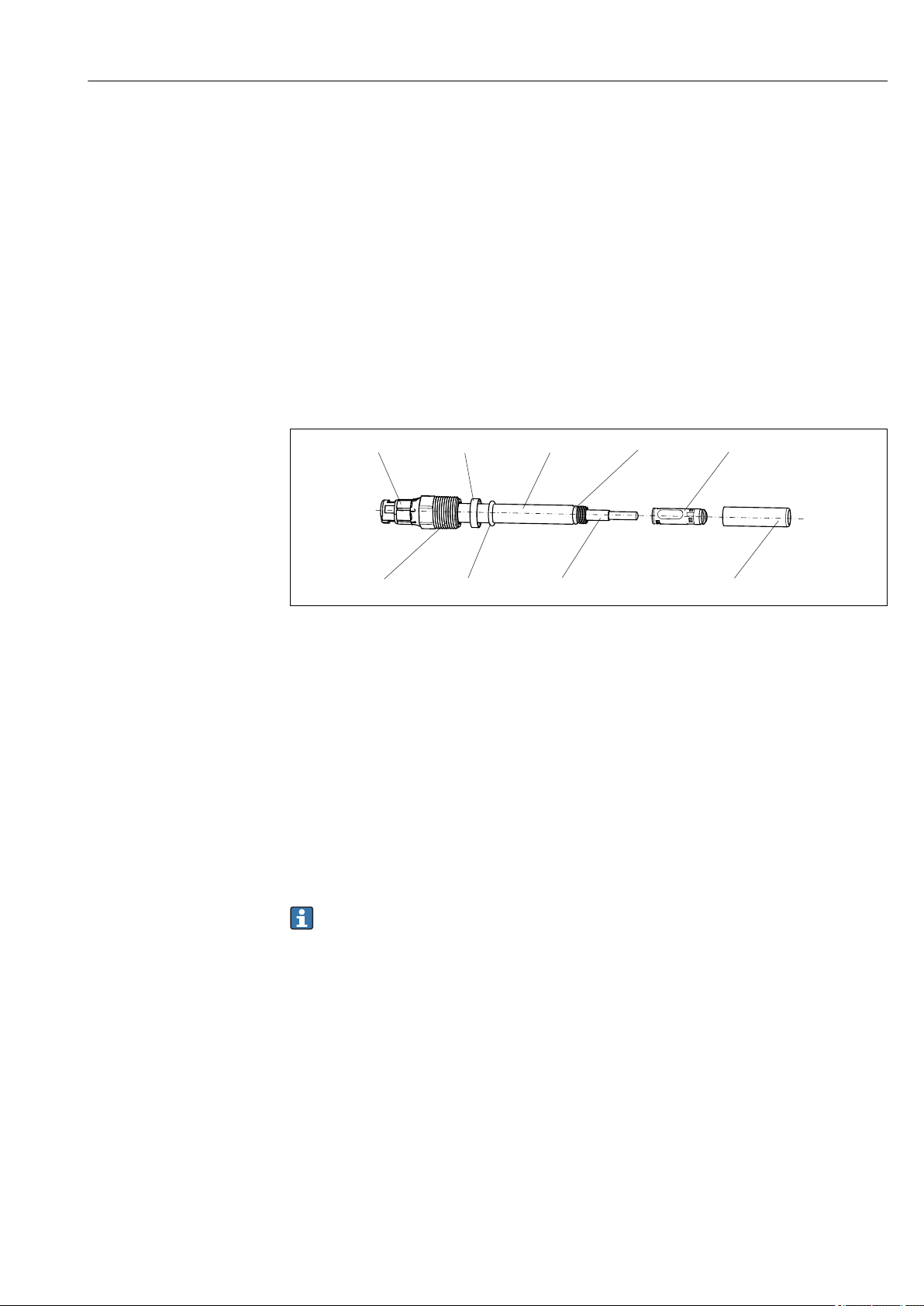
A0011869
1 COS22D
1
2
3
Plug-in head
Thrust collar
Sensor shaft
4
O-ring 8.5 x 1.5 mm
5
Membrane body
6
Shaft sleeve
7
Glass part with anode and cathode
8
Process seal 10.77 x 2.62 mm
9
Process connection Pg 13.5
3.3 Membrane body
The oxygen dissolved in the medium is transported to the membrane by the necessary
flow. The membrane is permeable for dissolved gases only. Other substances dissolved in
the liquid phase, e.g. ionic substances, will not penetrate through the membrane.
Therefore, medium conductivity has no impact on the measuring signal.
The sensor is shipped with a standard membrane body, which can be used for all common
applications. The membrane is pretensioned at the factory and can be installed
immediately.
Electrolytes are version-specific and cannot be mixed in a single application!
Endress+Hauser 9
Page 10

Device description, function Oxymax COS22D
3.4 Memosens technology
Sensors with Memosens protocol have an integrated electronics unit that stores calibration
data and other information. Once the sensor has been connected, the sensor data are
transferred automatically to the transmitter and used to calculate the measured value.
Call up the sensor data via the corresponding DIAG menu.
‣
Digital sensors can store measuring system data in the sensor. These include the following:
• Manufacturer data
• Serial number
• Order code
• Date of manufacture
• Calibration data
• Calibration date
• Calibration values
• Number of calibrations
• Serial number of the transmitter used to perform the last calibration
• Operating data
• Temperature application range
• Date of initial commissioning
• Hours of operation under extreme conditions
• Number of sterilizations
3.5 Polarization
When the sensor is connected to the transmitter, a fixed voltage is applied between the
cathode and anode. The polarization current this creates can be identified on the
transmitter with a reading that is initially high, but decreases with time. The sensor
cannot be calibrated until the reading is stable.
Reference value for nearly complete polarization of a sensor that was previously stored for
a long time:
• COS22D-*1: 2 hours
• COS22D-*3/4: 12 hours
After this time, even measurements close to the determination limit are useful. The
necessary polarization time is reduced for sensors that were in use shortly beforehand.
10 Endress+Hauser
Page 11

Oxymax COS22D Incoming acceptance and product identification
4 Incoming acceptance and product
identification
4.1 Incoming acceptance
1. Verify that the packaging is undamaged.
Notify the supplier of any damage to the packaging.
Keep the damaged packaging until the issue has been resolved.
2. Verify that the contents are undamaged.
Notify the supplier of any damage to the delivery contents.
Keep the damaged goods until the issue has been resolved.
3. Check that the delivery is complete and nothing is missing.
Compare the shipping documents with your order.
4. Pack the product for storage and transportation in such a way that it is protected
against impact and moisture.
The original packaging offers the best protection.
Make sure to comply with the permitted ambient conditions.
If you have any questions, please contact your supplier or your local Sales Center.
4.2 Product identification
4.2.1 Nameplate
The nameplate provides you with the following information on your device:
• Manufacturer identification
• Order code
• Extended order code
• Serial number
• Safety information and warnings
Compare the information on the nameplate with the order.
‣
4.2.2 Product identification
Product page
www.endress.com/cos22d
Interpreting the order code
The order code and serial number of your product can be found in the following locations:
• On the nameplate
• In the delivery papers
Obtaining information on the product
1. Go to www.endress.com.
2. Call up the site search (magnifying glass).
3. Enter a valid serial number.
4. Search.
The product structure is displayed in a popup window.
Endress+Hauser 11
Page 12

Incoming acceptance and product identification Oxymax COS22D
5. Click on the product image in the popup window.
A new window (Device Viewer) opens. All of the information relating to your
device is displayed in this window as well as the product documentation.
Manufacturer address
Endress+Hauser Conducta GmbH+Co. KG
Dieselstraße 24
D-70839 Gerlingen
4.3 Scope of delivery
The scope of delivery comprises:
• Oxygen sensor with watering cap (filled with tap water) for protecting the membrane
• Electrolyte, 1 bottle, 10 ml (0.34 fl.oz.)
• Tool to push out the membrane body
• Brief Operating Instructions
4.4 Certificates and approvals
4.4.1 Declaration of Conformity
The product meets the requirements of the harmonized European standards. As such, it
complies with the legal specifications of the EU directives. The manufacturer confirms
successful testing of the product by affixing to it the mark.
4.4.2 Ex approvals
Version COS22D-BA
ATEX II 1G / IECEx Ex ia IIC T3/T4/T6 Ga
4.4.3 Certification body
DEKRA EXAM GmbH
Bochum
4.4.4 Material certificates
Manufacturer declaration of FDA compatibility
The manufacturer declares the use of FDA-listed materials.
Product FDA certificate for
COS22D-****22 Membrane, O-rings, process seal
COS22Z-*2*2 Membrane, O-rings, process seal
COS22D-****23 Membrane, O-rings
COS22Z-*2*3 Membrane, O-rings
Hazardous area versions
For operation in FDA processes, another FDA-approved seal must be installed before
the process seal (for example CPA442). Doing so will sufficiently separate the process
from the Ex connection.
12 Endress+Hauser
Page 13

Oxymax COS22D Incoming acceptance and product identification
Material test certificate
A test certificate 3.1 in accordance with EN 10204 is supplied depending on the version (→
Product Configurator on the product page).
4.4.5 EHEDG
Compliance with EHEDG's criteria for hygienic design
• TÜV Rheinland, Apeldorn, Netherlands
• Certificate type: Type EL Class I
Endress+Hauser 13
Page 14
Installation Oxymax COS22D
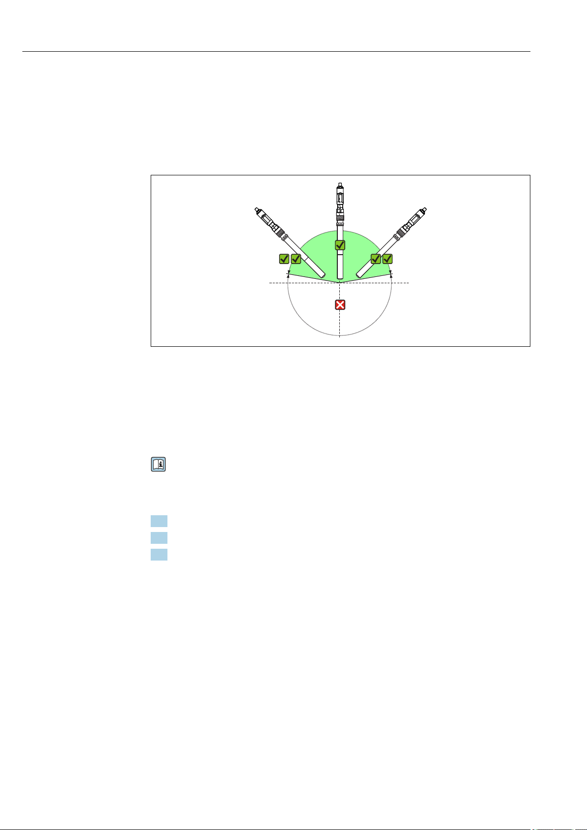
135°
10° 170°
45°
5 Installation
5.1 Installation conditions
5.1.1 Orientation
A0030545
2 Permitted orientations
The sensor must be installed at an angle of inclination of 10 to 170 ° in an assembly,
holder or appropriate process connection. Recommended angle: 45° to prevent the
attachment of air bubbles.
Inclination angles other than those mentioned are not permitted. In order to avoid buildup
and condensation on the spot, do not install the sensor upside down.
Follow the instructions for installing sensors in the Operating Instructions for the
assembly used.
5.1.2 Mounting location
1. Choose a mounting location that is easy to access.
2. Ensure that upright posts and assemblies are fully secured and vibration-free.
3. Choose a mounting location with an oxygen concentration that is typical for the
application.
5.2 Mounting the sensor
5.2.1 Measuring system
A complete measuring system comprises:
• an Oxymax COS22D oxygen sensor
• Measuring cable CYK10
• A transmitter, e.g. Liquiline CM42
• Optional: an assembly, e.g. permanent installation assembly CPA442, flow assembly
CPA240 or retractable assembly CPA875
14 Endress+Hauser
Page 15

Oxymax COS22D Installation
1
2
3
4
A0022853
3 Example of a measuring system with COS22D-*1
1 Liquiline CM42
2 Measuring cable CYK10
3 Oxymax COS22D-*1 digital oxygen sensor
4 Permanent installation assembly CPA442
5.2.2 Installing at a measuring point
Must be installed in a suitable assembly (depending on the application).
WARNING
L
Electrical voltage
In the event of a fault, non-grounded metallic assemblies may be live and as such are not
safe to touch!
When using metallic assemblies and installation equipment, national grounding
‣
provisions must be observed.
For complete installation of a measuring point, proceed as follows:
1. Install a retractable or a flow assembly (if used) into the process.
2. Connect the water supply to the rinse connections (if you are using an assembly with
a cleaning function).
3. Install and connect the oxygen sensor.
NOTICE
Installation error
Cable breakage, loss of sensor due to cable separation, unscrewing of membrane cap!
Do not install the sensor freely suspended from the cable.
‣
Screw the sensor into the assembly, ensuring that the cable is not twisted.
‣
Hold on to the sensor body during installation or removal. Turn only at the hexagonal
‣
nut of the armored coupling. Otherwise you might unscrew the membrane cap. This
will then remain in the assembly or process.
Avoid exerting excessive tensile force on the cable (e.g. through jerky pulling
‣
movements).
Choose a mounting location that is easy to access for later calibrations.
‣
Follow the instructions for installing sensors in the Operating Instructions for the
‣
assembly used.
Endress+Hauser 15
Page 16

Installation Oxymax COS22D
1
5
2
4
3
1 2
3
6
4
5
5.3 Installation examples
5.3.1 Permanent installation (CPA442)
The permanent installation assembly CPA442 enables easy adaptation of a sensor to
nearly any process connections from Ingold nozzles to Varivent or Tri-Clamp connections.
This kind of installation is very well suited for tanks and larger pipes. You will achieve a
defined immersion depth of the sensor into the medium in the simplest way.
5.3.2 Immersion operation
Universal holder and chain assembly
4 Chain holder on railing
1 Chain
2 Holder Flexdip CYH112
3 Rail
4 Sensor Oxymax
5 Wastewater assembly Flexdip CYA112
A0030564
5 Chain holder on upright post
1 Weather protection cover CYY101
2 Controller / transmitter
3 Chain
4 Wastewater assembly Flexdip CYA112
5 Sensor Oxymax
6 Holder Flexdip CYH112
A0030565
16 Endress+Hauser
Page 17

Oxymax COS22D Installation
1
2
3
4
5
2
3
4
Universal holder and fixed immersion tube
A0030567
6 Assembly holder with immersion tube
1 Protective cover
2 Controller / transmitter
3 Flexdip CYA112 immersion assembly
4 Sensor Oxymax
5 Assembly holder Flexdip CYH112
Basin rim mounting with immersion tube
A0030568
7 Basin rim mounting
1 Pendulum holder CYH112
2 Assembly Flexdip CYA112
3 Assembly float
4 Sensor Oxymax
Endress+Hauser 17
Page 18

Installation Oxymax COS22D
1
2
3
4
5
6
7
G1
800 (31.50)
500 (19.69)
220 (8.66)
Ø200 (7.87)
1
7
6
5
3
2
4
Float
The CYA112 float is for use in the case of large fluctuations in water level, for example in
rivers or lakes.
1 Cable run with strain relief and rain shield
2 Fixing ring for rope and chains with terminal screw
3 Eyelets Ø15, 3 x 120 ° for anchoring
4 Plastic float, resistant to salt water
5 Pipe 40 x 1, stainless steel 1.4571
6 Bumper and ballast
7 Oxygen sensor
A0032159
8 Dimensions in mm (inch)
5.3.3 Flow assembly
CPA240
The flow assembly CPA240 offers up to three installation spaces for sensors with a shaft
diameter of 12 mm (0.47"), a shaft length of 120 mm (4.7"), and a Pg 13.5 process
connection. It very well suited for use in pipelines or hose connections. To prevent
measured error with trace measurements, pay particular attention to complete ventilation
of the assembly.
18 Endress+Hauser
A0005720
9 Flow assembly CPA240 with protective cover
10 Bypass installation
1 Main pipe
2 Medium removal
3, 6 Manually actuated or solenoid valves
4 Sampling
5 Flow assembly with installed sensor
7 Medium return
A0005721
Page 19

Oxymax COS22D Installation
1 2
3
5
3
41
2
3
4
2
Flow assembly for water treatment and processes
The compact stainless steel assembly offers space for a 12-mm sensor with a length of
120 mm. The assembly has a low sampling volume and, with the 6-mm connections, it is
best suited for residual oxygen measurement in water treatments and boiler feedwater.
The flow comes from below.
A0014081
11 Flow assembly
1 Built-in sensor
2 Drain
3 Wall mount (clamp D29)
4 Inflow
5.3.4 Retractable assembly (CPA875 or CPA450)
The assembly is designed for installation on tanks and pipes. Suitable nozzles must be
available for this.
Install the assembly at places with constant flow. The minimum pipe diameter is DN 80.
A0005722-EN
Endress+Hauser 19
12 Permissible and impermissible sensor installation positions with retractable assembly
1 Ascending pipe, best position
2 Horizontal pipe, sensor top down, impermissible due to air cushion or foam bubble forming
3 Horizontal pipe, lateral installation with permissible installation angle (acc. to sensor version)
4 Upside-down installation, unsuitable
5 Down pipe, impermissible
Page 20

Installation Oxymax COS22D
NOTICE
Sensor not in the medium all the way, buildup, upside-down installation
These can all cause incorrect measurements!
Do not install assembly at points where air pockets or bubbles may form.
‣
Avoid or regularly remove deposits on the sensor membrane.
‣
Do not install sensor upside down.
‣
5.4 Post-installation check
1. Are the sensor and cable undamaged?
2. Is the orientation correct?
3. Is the sensor installed in an assembly and is not suspended from the cable?
4. Avoid the penetration of moisture by fitting the protection cap on the immersion
assembly.
20 Endress+Hauser
Page 21

Oxymax COS22D Electrical connection
COS22D
CYK10
Ex ia
II 2G
II 1G
II 3G
Zone 1
Zone 0
Zone 2
Ex ib
6 Electrical connection
WARNING
L
Device is live!
Incorrect connection may result in injury or death!
The electrical connection may be performed only by an electrical technician.
‣
The electrical technician must have read and understood these Operating Instructions
‣
and must follow the instructions contained therein.
Prior to commencing connection work, ensure that no voltage is present on any cable.
‣
6.1 Quick wiring guide (COS22D-BA/NA only)
A0024123
13
Endress+Hauser 21
Page 22

Electrical connection Oxymax COS22D
GN/YE
YE
GN
BN
WH
GND
+
–
Com A
Com B
GY
6.2 Connecting the sensor
The electrical connection simulator to the transmitter is established using measuring cable
CYK10.
A0024019
14 Measuring cable CYK10
6.3 Ensuring the degree of protection
Only the mechanical and electrical connections which are described in these instructions
and which are necessary for the required, designated use, may be carried out on the device
delivered.
Exercise care when carrying out the work.
‣
Otherwise, the individual types of protection (Ingress Protection (IP), electrical safety, EMC
interference immunity) agreed for this product can no longer be guaranteed due,
for example to covers being left off or cable (ends) that are loose or insufficiently secured.
6.4 Post-connection check
Device condition and specifications Notes
Are the sensor, assembly, or cables free from damage on the
outside?
Electrical connection Notes
Are the mounted cables strain-relieved and not twisted?
Is a sufficient length of the cable cores stripped, and are the cores
positioned in the terminal correctly?
Are all the screw terminals properly tightened? Tighten
Are all cable entries mounted, tightened and leak-tight? For lateral cable entries, make sure the
Are all cable entries installed downwards or mounted laterally?
Visual inspection
Check the fit (by pulling gently)
cables loop downwards to allow water to
drip off
22 Endress+Hauser
Page 23

Oxymax COS22D Calibration and adjustment
7 Calibration and adjustment
Calibration is a means of adapting the transmitter to the characteristic values of the
sensor.
Calibration of the sensor is essential according to:
• Initial commissioning
• Changing the membrane or electrolyte
• Long pauses in operation without power supply
Within the framework of system monitoring, for example, calibration can also be cyclically
monitored (at typical time intervals, depending on operating experience) or renewed.
7.1 Types of calibration
You can carry out a slope or zero point calibration for the sensor.
In most applications, single-point calibration in the presence of oxygen is sufficient
(=calibration of the sensor slope). When switching from process to calibration conditions,
you have to allow a longer settling time for the sensor.
The additional calibration of the zero point improves the accuracy of the measurement
results at trace concentrations. You can calibrate the zero point using nitrogen (min.
99.995%) or oxygen-free water. Make sure that the sensor is polarized and the measured
value is settled at the zero point (at least 20-30 minutes) to prevent later incorrect
measurements at trace concentrations.
The following describes calibration of the slope in air (saturated with water vapor) as the
easiest and recommended calibration method. However, this type of calibration is possible
only if the air temperature is ≥ 0 °C (32 °F).
7.2 Calibration in air
1. Remove the sensor from the medium.
2. Clean the outside of the sensor with a damp cloth.
3. Allow a temperature compensation time of approx. 20 minutes for the sensor in the
ambient air. Make sure that the sensor is not exposed to any direct ambient effects
(direct sunlight, drafts) during this time.
4. Is the measured value display on the transmitter stable:
Perform the calibration in accordance with the Operating Instructions for the
transmitter. Pay particular attention to the software settings for the stability criteria
for calibration and for the ambient pressure.
5. Where necessary:
Adjust sensor.
6. Then place the sensor back into the medium.
Follow the calibration instructions in the Operating Instructions for the transmitter
‣
used.
7.3 Calculation example for the calibration value
As a check, you can calculate the expected calibration value (transmitter display) as shown
in the following example (salinity is 0).
1. Determine the following:
Endress+Hauser 23
Page 24

Calibration and adjustment Oxymax COS22D
• The ambient temperature for the sensor (air temperature for Air 100% rh or calibration
methods Air variable, water temperature for H2O air-saturatedcalibration method)
• The altitude above sea level
• The current air pressure (= relative air pressure based on sea level) at the time of
calibration. (If undeterminable, use 1013 hPa.)
2. Determine the following:
• The saturation value S acc. to Table 1
• The altitude factor K acc. to Table 2
Table 1
T
[˚C (˚F)]S[mg/l=ppm]T[˚C (˚F)]S[mg/l=ppm]T[˚C (˚F)]S[mg/l=ppm]T[˚C (˚F)]S[mg/l=ppm]
0 (32) 14.64 11 (52) 10.99 21 (70) 8.90 31 (88) 7.42
1 (34) 14.23 12 (54) 10.75 22 (72) 8.73 32 (90) 7.30
2 (36) 13.83 13 (55) 10.51 23 (73) 8.57 33 (91) 7.18
3 (37) 13.45 14 (57) 10.28 24 (75) 8.41 34 (93) 7.06
4 (39) 13.09 15 (59) 10.06 25 (77) 8.25 35 (95) 6.94
5 (41) 12.75 16 (61) 9.85 26 (79) 8.11 36 (97) 6.83
6 (43) 12.42 17 (63) 9.64 27 (81) 7.96 37 (99) 6.72
7 (45) 12.11 18 (64) 9.45 28 (82) 7.82 38 (100) 6.61
8 (46) 11.81 19 (66) 9.26 29 (84) 7.69 39 (102) 6.51
9 (48) 11.53 20 (68) 9.08 30 (86) 7.55 40 (104) 6.41
10 (50) 11.25
Table 2
Altitude
[m (ft)]
0 (0) 1.000 550 (1800) 0.938 1050 (3450) 0.885 1550 (5090) 0.834
50 (160) 0.994 600 (1980) 0.932 1100 (3610) 0.879 1600 (5250) 0.830
100 (330) 0.988 650 (2130) 0.927 1150 (3770) 0.874 1650 (5410) 0.825
150 (490) 0.982 700 (2300) 0.922 1200 (3940) 0.869 1700 (5580) 0.820
200 (660) 0.977 750 (2460) 0.916 1250 (4100) 0.864 1750 (5740) 0.815
250 (820) 0.971 800 (2620) 0.911 1300 (4270) 0.859 1800 (5910) 0.810
300 (980) 0.966 850 (2790) 0.905 1350 (4430) 0.854 1850 (6070) 0.805
350 (1150) 0.960 900 (2950) 0.900 1400 (4600) 0.849 1900 (6230) 0.801
400 (1320) 0.954 950 (3120) 0.895 1450 (4760) 0.844 1950 (6400) 0.796
450 (1480) 0.949 1000 (3300) 0.890 1500 (4920) 0.839 2000 (6560) 0.792
500 (1650) 0.943
K Altitude
[m (ft)]
K Altitude
[m (ft)]
K Altitude
[m (ft)]
3. Calculate factor L:
Relative air pressure at calibration
L= -----------------------------------------------
1013 hPa
K
4. Calculate calibration value C:
24 Endress+Hauser
Page 25

Oxymax COS22D Calibration and adjustment
C = S . K . L
Example
• Air calibration at 18 °C (64 °F), altitude 500 m (1650 ft) above sea level, current air
pressure 1009 hPa
• S = 9.45 mg/l, K = 0.943, L = 0.996
• Calibration value C = 8.88 mg/l.
You do not need factor K in the table if your measuring device returns the absolute air
pressure L
for calculation is then: C = S . L
(air pressure depending on altitude) as the measured value. The formula
abs
.
abs
7.4 Zero point calibration
The zero point is not so important when working with relatively high concentrations of
oxygen.
However, once oxygen sensors are used at low concentrations and in the trace range, they
must also be calibrated at the zero point.
Zero point calibrations are demanding as the ambient medium - usually air - already has a
high oxygen content. This oxygen must be blocked off for zero point calibration of the
sensor.
A calibration with zero-point gel can be used here:
The oxygen-depleting gel COY8 (→ 35)creates an oxygen-free medium for zero point
calibration.
Prior to sensor zero point calibration, check the following:
• Is the sensor signal stable?
• Is the value displayed plausible?
1. If the sensor signal is stable:
Calibrate the zero point.
2. If necessary:
Adjust the sensor to the zero point.
The reference method (sample calibration in zero point) can also be used here if
appropriate collecting vessels or reference measurement are available.
If the oxygen sensor is calibrated too early, this can result in an incorrect zero point.
Rule of thumb: Operate the sensor in zero-point gel for at least 0.5 h.
If the sensor was already operated in the trace range before the zero point calibration,
the time specified above generally suffices. If the sensor was operated in air,
significantly more time must be factored in to also remove residual oxygen from any
dead volume inherent to the design. Here a value of 2 hours applies as a general rule.
Follow the instructions in the kit documentation enclosed with the zero-point gel.
Endress+Hauser 25
Page 26

Commissioning Oxymax COS22D
8 Commissioning
8.1 Function check
Prior to initial commissioning, ensure that:
• The sensor is correctly installed
• The electrical connection is correct
• There is sufficient electrolyte in the membrane cap
The transmitter is not displaying a warning about electrolyte depletion
Please note the information on the safety data sheet to ensure safe use of the
electrolyte.
If using an assembly with automatic cleaning function:
Check that the cleaning medium (water or air, for example) is connected correctly.
‣
WARNING
L
Escaping process medium
Risk of injury from high pressure, high temperatures or chemical hazards!
Before applying pressure to an assembly with cleaning system, ensure that the system
‣
has been connected correctly.
If you cannot reliably establish the correct connection, do not install the assembly in
‣
the process.
Following commissioning, the sensor must be serviced at regular intervals, as only
then can reliable measurement be guaranteed.
Operating Instructions for the transmitter used, such as BA01245C if using the
Liquiline CM44x or CM44xR.
8.2 Sensor polarization
NOTICE
Incorrect measurements due to ambient influences!
Always avoid strong direct sunlight on the sensor.
‣
Comply with the instructions for commissioning in the Operating Instructions of the
‣
transmitter used.
The sensor has been tested at the factory for proper functioning and is shipped in a
condition in which it is ready to operate.
To prepare for calibration:
1. Remove the sensor protection cap.
2. Expose the sensor, which is dry on the outside, to the air atmosphere.
The air should be saturated with water vapor. Therefore, install the sensor as
close as possible to a water surface. However, the sensor membrane must remain
dry during calibration. Therefore, avoid direct contact with the water surface.
3. Connect the sensor to the transmitter.
4. Switch on the transmitter.
When the sensor is connected to the transmitter, the polarization takes place
automatically after the transmitter powers up.
5. Wait for polarization time to elapse.
26 Endress+Hauser
Page 27

Oxymax COS22D Commissioning
8.3 Sensor calibration
Calibrate the sensor (e.g. air calibration) immediately after the polarization time elapses.
The calibration intervals depend greatly on:
• The application
• The installation position of the sensor
The following method helps you determine the necessary calibration intervals:
1. Inspect the sensor one month after commissioning. To do so, remove the sensor from
the medium and dry it off.
2. After 10 minutes, measure the oxygen saturation index in air.
Decide using the results:
a) Measured value not 100 ±2 %SAT? → Calibrate the sensor.
b) Measured value = 100 ±2 %SAT? → Double the length of time to the next
inspection.
3. Proceed as indicated in Step 1 after two, four and eight months.
This allows you to determine the optimum calibration interval for your sensor.
In any case, calibrate the sensor at least once a year.
Endress+Hauser 27
Page 28

Troubleshooting Oxymax COS22D
9 Troubleshooting
If one of the following problems is present:
‣
Check the measuring system in the order shown.
Problem Testing Remedial action
Nothing displayed, no reaction
from the sensor
Displayed value too high Polarization ended?
Displayed value too low Is sensor calibrated/adjusted?
Display value fluctuating greatly Membrane visibly stretched?
Power supply to the transmitter?
Sensor cable connected correctly?
Medium flow present?
Deposit buildup on the membrane?
No electrolyte in the measuring
chamber?
Is sensor calibrated/adjusted?
Displayed temperature clearly too
low?
Membrane visibly stretched?
Electrolyte contaminated?
Open the sensor and dry the
electrodes. Is the transmitter
reading now at 0?
Medium flow present?
Displayed temperature clearly too
high?
Deposit buildup on the membrane?
Electrolyte contaminated?
Open the sensor and dry the
electrodes. Is the transmitter
reading now at 0?
Connect power supply.
‣
Establish correct connection.
‣
Create medium flow.
‣
Clean sensor.
‣
Refill or replace electrolyte.
‣
Wait for polarization time to
‣
elapse.
Recalibrate/readjust.
‣
Check sensor, if necessary send
‣
sensor in for repair.
Replace membrane cap.
‣
Replace electrolyte.
‣
1. Check the cable connection.
2. If the problem persists:
Send sensor in for repair.
Recalibrate/readjust.
‣
Create medium flow.
‣
Check sensor, if necessary send
‣
sensor in for repair.
Clean sensor.
‣
Replace electrolyte.
‣
Replace membrane cap.
‣
1. Check the cable connection.
2. If the problem persists:
Send sensor in for repair.
1. Pay attention to the troubleshooting information in the Operating Instructions for
the transmitter.
2. Check the transmitter if necessary.
28 Endress+Hauser
Page 29

Oxymax COS22D Maintenance
10 Maintenance
Take all the necessary precautions in time to ensure the operational safety and reliability
of the entire measuring system.
NOTICE
Effects on process and process control!
When carrying out any work on the system, bear in mind any potential impact this
‣
could have on the process control system and the process itself.
For your own safety, only use genuine accessories. With genuine parts, the function,
‣
accuracy and reliability are also ensured after maintenance work.
10.1 Maintenance schedule
Maintenance cycles depend to a great extent on the operating conditions.
The following rule of thumb applies:
• Constant conditions, e.g. Power plant = long cycles (1/2 year)
• Widely varying conditions, e.g. daily CIP or SIP cleaning = short cycles (1 month or
shorter)
The following method helps you determine the necessary intervals:
1. Inspect the sensor one month after commissioning. To do so, remove the sensor from
the medium and dry it.
2. After 10 minutes, measure the oxygen saturation index in air.
Decide using the results:
a) Measured value not 100 ±2 %SAT? → Service the sensor.
b) Measured value = 100 ±2 %SAT? → Double the length of time to the next
inspection.
3. Proceed as indicated in Step 1 after two, four and eight months.
This allows you to determine the optimum maintenance interval for your sensor.
Particularly in the case of widely fluctuating process conditions, damage may occur to
the membrane even within a maintenance cycle. You can recognize this by
implausible sensor behavior. (→ 28)
10.2 Maintenance tasks
The following tasks are mandatory:
1. Clean the sensor glass body with anode and cathode (particularly if the membrane is
dirty). → 29
2. Replace wear parts or consumables. → 30
3. Check measurement function. → 33
4. Recalibrate (if desired or necessary).
Follow the Operating Instructions for the transmitter.
10.3 Cleaning of sensor
The measurement can be corrupted by sensor fouling or malfunction due to the following,
for example:
Deposit buildup on the sensor membrane
This results in a longer response time and, under certain circumstances, a reduced
slope.
Endress+Hauser 29
Page 30

Maintenance Oxymax COS22D
1 2
3
4
5
78
9
6
For reliable measurement, the sensor must be cleaned at regular intervals. The frequency
and intensity of the cleaning operation depend on the medium.
Clean the sensor:
• Before every calibration
• At regular intervals during operation as necessary
• Before returning it for repairs
Type of contamination Cleaning
Salt deposits 1. Immerse the sensor in drinking water or in 1-5 % hydrochloric
acid (for a few minutes).
2. Then rinse it with copious amounts of water.
Dirt particles on the sensor shaft and
shaft sleeve (not membrane!)
Dirt particles on membrane or
membrane body
After cleaning:
‣
Clean sensor shaft and sleeve with water and a suitable sponge.
‣
Clean the membrane with water and a soft cloth.
‣
Rinse with copious amounts of clean water.
10.4 Wear parts and consumables
Parts of the sensor are subject to wear during operation. By taking suitable measures, you
can restore the normal operating function.
Corrective action Reason
Replace sealing rings Visible damage to a sealing ring
Replace electrolyte Unstable or implausible measuring signal or fouling of the electrolyte
Replace membrane body Membrane is damaged or can no longer be cleaned (hole or overstretching)
A0011869
15 COS22D
1
2
3
Plug-in head
Thrust collar
Sensor shaft
4
O-ring 8.5 x 1.5 mm
5
Membrane body
6
Shaft sleeve
7
Glass part with anode and cathode
8
Process seal 10.77 x 2.62 mm
9
Process connection Pg 13.5
30 Endress+Hauser
Page 31

Oxymax COS22D Maintenance
10.4.1 Replacing sealing rings
It is compulsory to replace the sealing ring if it is visibly damaged. For replacement, use
only original sealing rings.
The following O-rings can be replaced:
• Sealing ring for shaft sleeve: item 4 → 30
• Sealing ring to process (conductive for Ex): item 8
If the sealing ring on the membrane body (item 5) is damaged, you must replace the entire
membrane body.
10.4.2 Replacing electrolyte
The electrolyte is used up gradually during operation. This is caused by electrochemical
substance reactions. In de-energized state, no substance reactions take place, and the
electrolyte is not used up. The operating time of the electrolyte is shortened by diffusion of
dissolved gases such as H2S, NH3 or high concentrations of CO2.
Theoretical operating time at pO2 = 210 mbar and T=25 ˚C (77 ˚F)
COS22D-*1 (standard sensor): > 1.5 years
COS22D-*3/4 (trace sensor): > 3 months
CAUTION
L
The standard electrolyte is a strong irritant
Danger of severe skin and eye irritation!
Be absolutely certain to observe the corresponding workplace safety regulations.
‣
Wear protective gloves and goggles when handling the electrolyte.
‣
In case of eye contact: Remove contact lenses, rinse eyes with water for a few minutes
‣
and contact a doctor.
In case of skin contact: Take off wet clothing immediately, wash the skin or take a
‣
shower.
Generally, the following applies:
• The electrolyte must be changed if the membrane body is detached.
• Sensors operated close to the zero point consume hardly any chemical electrolyte. The
electrolyte does not have to be replaced for a long period.
• Sensors operated at high oxygen partial pressures (> 100 hPa) consume a significant
amount of electrolyte. The electrolyte has to be replaced frequently.
• 25 ml of electrolyte is enough to fill the membrane body approx. 15 times.
Draining the electrolyte
1. Disconnect the sensor from the transmitter and remove it from the medium.
2. Clean the exterior of the sensor.
3. Hold the sensor vertically and unscrew the shaft sleeve.
The membrane body is either in the shaft sleeve or is still on the glass part with
the anode and cathode.
4. Remove the membrane body. For this purpose, use the tool provided to push out the
membrane body.
5. Drain the membrane body and rinse it with potable water.
Topping up the electrolyte and installing the membrane body
1. Pour fresh electrolyte from the supply bottle into the membrane body.
2. Remove all air bubbles from the electrolyte by tapping the side of the membrane body
(using a pen or pencil, for example).
3. Hold the sensor vertically and carefully fit the membrane body, filled with electrolyte,
onto the glass part.
Endress+Hauser 31
Page 32

Maintenance Oxymax COS22D
4. Carefully screw on the shaft sleeve and tighten until the stop.
Putting the sensor back into operation
1. Connect the sensor to the transmitter.
2. Polarize the sensor and recalibrate it.
3. After this:
Re-immerse the sensor into the medium.
4. Check that the transmitter does not signal an alarm.
10.4.3 Replacing the membrane body
Removing the membrane body
1. Disconnect the sensor from the transmitter and remove it from the medium.
2. Clean the exterior of the sensor.
3. Hold the sensor vertically and unscrew the shaft sleeve.
The membrane body is either in the shaft sleeve or is still on the glass part with
the anode and cathode.
4. Remove the membrane body. For this purpose, use the tool provided to push out the
membrane body.
5. Dispose of the old membrane body and the old electrolyte.
6. Take a new membrane body out of its packaging.
Topping up the electrolyte and installing the membrane body
1. Pour fresh electrolyte from the supply bottle into the membrane body.
2. Remove all air bubbles from the electrolyte by tapping the side of the membrane body
(using a pen or pencil, for example).
3. Hold the sensor vertically and carefully fit the membrane body, filled with electrolyte,
onto the glass part.
4. Carefully screw on the shaft sleeve and tighten until the stop.
Putting the sensor back into operation
1. Connect the sensor to the transmitter.
2. Polarize the sensor and recalibrate it.
3. After this:
Re-immerse the sensor into the medium.
4. Check that the transmitter does not signal an alarm.
10.4.4 Replacing glass body with cathode
NOTICE
Polishing the cathode can cause the impaired functioning or total failure of the
sensor!
Do not clean the cathode mechanically.
‣
If the cathode is coated with buildup replace the glass body:
1. Hold the sensor vertically and unscrew the shaft sleeve: item 6 → 30.
2. If the membrane body (item 5) remains on the glass body (item 7) and not in the
shaft sleeve:
Remove it from the glass body.
3. Rinse the glass body, along with the anode and cathode, using distilled water.
32 Endress+Hauser
Page 33

Oxymax COS22D Maintenance
4. Pull the used glass body out of the holder.
5. Dry the inside of the electrode holder.
6. Plug a new glass body (from the membrane kit) into the holder so that it fits. When
doing so, ensure that you do not damage the electrical contact pins.
7. Fill the membrane body with electrolyte and screw the shaft sleeve back on.
10.5 Checking the measurement function
1. Remove the sensor from the medium.
2. Clean and dry the membrane.
3. After about 10 minutes, measure the oxygen saturation index in air (without
recalibration).
The measured value should be at 100 ± 2 % SAT.
Endress+Hauser 33
Page 34

Accessories Oxymax COS22D
11 Accessories
The following are the most important accessories available at the time this documentation
was issued.
For accessories not listed here, please contact your Service or Sales Center.
‣
11.1 Assemblies (selection)
Cleanfit CPA875
• Retractable process assembly for sterile and hygienic applications
• For in-line measurement with standard sensors with 12 mm diameter, e.g. for pH, ORP,
oxygen
• Product Configurator on the product page: www.endress.com/cpa875
Technical Information TI01168C
Flowfit CPA240
• pH/redox flow assembly for processes with stringent requirements
• Product Configurator on the product page: www.endress.com/cpa240
Technical Information TI00179C
Unifit CPA442
• Installation assembly for food, biotechnology and pharmaceutics
• With EHEDG and 3A certificate
• Product Configurator on the product page: www.endress.com/cpa442
Technical Information TI00306C
Cleanfit CPA450
• Manual retractable assembly for installing sensors with a diameter of 120 mm in tanks
and pipes
• Product Configurator on the product page: www.endress.com/cpa450
Technical Information TI00183C
Flow assembly
• For sensors with Ø 12 mm and length 120 mm
• Compact stainless steel assembly with low sampling volume
• Order No.: 71042404
11.2 Measuring cable
11.2.1 Cable for COS22D
Memosens data cable CYK10
• For digital sensors with Memosens technology
• Product Configurator on the product page: www.endress.com/cyk10
Technical Information TI00118C
Memosens data cable CYK11
• Extension cable for digital sensors with Memosens protocol
• Product Configurator on the product page: www.endress.com/cyk11
Technical Information TI00118C
34 Endress+Hauser
Page 35

Oxymax COS22D Accessories
11.3 Zero-point gel
COY8
Zero-point gel for oxygen and disinfection sensors
• Oxygen-free and chlorine-free gel for the verification, zero point calibration and
adjustment of oxygen and disinfection measuring points
• Product Configurator on the product page: www.endress.com/coy8
Technical Information TI01244C
11.4 Maintenance kit
COS22Z
• Service Kit, COS22 and COS22D
• Ordering information: www.endress.com/cos22d under "Accessories/spare parts"
Endress+Hauser 35
Page 36

Repair Oxymax COS22D
12 Repair
12.1 Spare parts and consumables
COS22Z
• Service Kit, COS22 and COS22D
• Ordering information: www.endress.com/cos22d under "Accessories/spare parts"
12.2 Return
The product must be returned if repairs or a factory calibration are required, or if the
wrong product was ordered or delivered. As an ISO-certified company and also due to legal
regulations, Endress+Hauser is obliged to follow certain procedures when handling any
returned products that have been in contact with medium.
To ensure the swift, safe and professional return of the device:
Refer to the website www.endress.com/support/return-material for information on the
‣
procedure and conditions for returning devices.
12.3 Disposal
The device contains electronic components. The product must be disposed of as electronic
waste.
Observe the local regulations.
‣
36 Endress+Hauser
Page 37

Oxymax COS22D Technical data
13 Technical data
13.1 Input
Measured variables Dissolved oxygen [mg/l, µg/l, ppm, ppb or %SAT or hPa]
Temperature [˚C, ˚F]
Measuring ranges Measuring ranges apply for 25 ˚C (77 ˚F) and 1013 hPa (15 psi)
Measuring range Optimum operational range
COS22D-*1 0.01 to 60 mg/l
0 to 600 % SAT
0 to 1200 hPa
0 to 100 Vol%
COS22D-*3/4 0.001 to 10 mg/l
0 to 120 % SAT
0 to 250 hPa
0 to 25 Vol%
1) Applications in this range guarantee a long service life and minimum maintenance
0.01 to 20 mg/l
0 to 200 % SAT
0 to 400 hPa
0 to 40 Vol%
0.001 to 2 mg/l
0 to 20 % SAT
0 to 40 hPa
0 to 4 Vol%
13.2 Performance characteristics
Response time From air to nitrogen at reference operating conditions:
• t90 : < 30 s
• t98 : < 60 s
Reference operating conditions
Reference temperature: 25 °C (77 °F)
Reference pressure: 1013 hPa (15 psi)
Reference application: Air-saturated water
1)
Signal current in air COS22D-*1 (standard sensor): 40 to 100 nA
COS22D-*3/4 (trace sensor): 210 to 451 nA
Zero current COS22D-*1 (standard sensor): < 0.1 % of the signal current in air
COS22D-*3/4 (trace sensor): < 0.03 % of the signal current in air
Measured value resolution
COS22D-*1 (standard sensor): 10 ppb in aqueous, 0.2 hPa or 0.02 Vol% in
gaseous media
COS22D-*3/4 (trace sensor): 1 ppb in aqueous, 0.02 hPa or 0.002 Vol%
in gaseous media
Corresponds to the recommended measured value resolution at the transmitter
Endress+Hauser 37
Page 38

Technical data Oxymax COS22D
Maximum measured
1)
error
COS22D-*1 (standard sensor): ≤ ±1 % of measuring range + 10 ppb
COS22D-*3/4 (trace sensor): ≤ ±1 % of measuring range + 1 ppb
*
at reference operating conditions
*
Long-term drift < 4 % per month in reference operating conditions
≤ 1 % per month in operation with reduced oxygen concentration (< 4 Vol% O2)
Influence of the medium
Pressure compensation not required
pressure
Polarization time COS22D-*1 (standard sensor): < 30 min for 98% signal value, 2 h for
100%
COS22D-*3/4 (trace sensor): < 3 h for 98% signal value, 12 h for 100%
Intrinsic oxygen consumption
Operating time of the electrolyte
COS22D-*1 (standard sensor): Approx. 20 ng/h in air at 25 ˚C (77 ˚F)
COS22D-*3/4 (trace sensor): Approx. 100 ng/h in air at 25 ˚C (77 ˚F
The electrolyte is used up gradually during operation. This is caused by electrochemical
substance reactions. In de-energized state, no substance reactions take place, and the
electrolyte is not used up. The operating time of the electrolyte is shortened by diffusion of
dissolved gases such as H2S, NH3 or high concentrations of CO2.
*
Theoretical operating time at pO2 = 210 mbar and T=25 ˚C (77 ˚F)
COS22D-*1 (standard sensor): > 1.5 years
COS22D-*3/4 (trace sensor): > 3 months
CAUTION
L
The standard electrolyte is a strong irritant
Danger of severe skin and eye irritation!
Be absolutely certain to observe the corresponding workplace safety regulations.
‣
Wear protective gloves and goggles when handling the electrolyte.
‣
In case of eye contact: Remove contact lenses, rinse eyes with water for a few minutes
‣
and contact a doctor.
In case of skin contact: Take off wet clothing immediately, wash the skin or take a
‣
shower.
Generally, the following applies:
• The electrolyte must be changed if the membrane body is detached.
• Sensors operated close to the zero point consume hardly any chemical electrolyte. The
electrolyte does not have to be replaced for a long period.
• Sensors operated at high oxygen partial pressures (> 100 hPa) consume a significant
amount of electrolyte. The electrolyte has to be replaced frequently.
• 25 ml of electrolyte is enough to fill the membrane body approx. 15 times.
Temperature compensation Compensation of the membrane properties takes place in the transmitter between -5 and
90˚C (23 to 194 ˚F); above 90˚C (194 ˚F), extrapolation takes place
• Measured variable as partial pressure [hPa] or in Vol%: -5 to 90 ˚C (23 to 194 ˚F)
• Measured variable as concentration [mg/l]: 0 to 80 ˚C (32 to 176 ˚F)
• Measured variable as saturation [%SAT]: -5 to 90 ˚C (23 to 194 ˚F)
1) In accordance with IEC 60746-1 at rated operating conditions
38 Endress+Hauser
Page 39

Oxymax COS22D Technical data
80
176
-5230
32
A B
90
194
C
T
[°C]
T
[°F]
p
T
[bar]
[°C]
6
12
135
80
[psi]
174
87
T
[°F]
176
275
-5230
32
A0011887
13.3 Environment
Ambient temperature range
COS22D-*1 /3: -5 to +135 °C (23 to 275 °F), non-freezing
COS22D-*4: -5 to +50 °C (23 to 120 °F), non-freezing
Storage temperature –5 to +50 ˚C (20 to 120 ˚F) at 95% relative humidity, non-condensing
NOTICE
Danger of sensor drying out!
Store the sensor with the watering cap only (filled with tap water).
‣
Degree of protection IP 68 (10 m (33 ft) head of water at 25 ˚C (77 ˚F) over 45 days, 1 mol/l KCl)
Humidity 0 to 100%, condensating
13.4 Process
Process temperature COS22D-*1 /3 (standard/trace sensor): -5 to +135 °C (23 to 275 °F), non-freezing
COS22D-*4 (trace sensor, gold): -5 to +80 °C (23 to 180 °F), non-freezing
Process pressure Ambient pressure ... 12 bar (... 174 psi) absolute
Temperature-pressure ratings
Endress+Hauser 39
A0028771-EN
Page 40

Technical data Oxymax COS22D
Pg 13,5
50 (1.97)
120 / 225 / 360 / 420 (4.72 / 8.86 / 14.2 / 16.5)*
12 - 0.1
(0.47)
Minimum flow COS22D-*1 (standard sensor): 0.02 m/s (0.07 ft/s)
COS22D-*3/4 (trace sensor): 0.1 m/s (0.33 ft/s)
Chemical resistance Parts in contact with the medium are chemically resistant to:
• Diluted acids and alkalis
• Hot water and superheated steam up to max. 135 ˚C (275 ˚F)
• CO2 up to 100 %, only with trace sensor COS22D-*3
NOTICE
Hydrogen sulfide and ammonia shorten the operating life of the sensor!
Do not use the sensor in applications where it is exposed to hydrogen sulfide or
‣
ammonia vapors.
Cross-sensitivity COS22D-*1/3
Molecular hydrogen causes false low readings and can, in a worst-case scenario, result in
total failure of the sensor.
No cross interference from hydrogen with the COS22D-*4 version.
CIP compatibility Yes ( COS22D-*1/3 )
SIP compatibility Yes, max. 140 °C (284 °F) ( COS22D-*1/3 )
Autoclavability Yes, max. 140 °C (284 °F), max. 30 min. (COS22D-*1/3)
13.5 Mechanical construction
Dimensions
16 Dimensions in mm (inch)
A0011881
40 Endress+Hauser
Page 41

Oxymax COS22D Technical data
28 (1.10)
Ø6 (0.24)
39 (1.54)
160 (6.30)
30
(1.18)
Ø6 (0.24)
Ø 29 x 1.5 (1.14 x 0.06)
Flow assembly for sensors with Ø 12 mm (accessories)
17 Dimensions in mm (inch)
Weight Depending on the design (length)
0.2 kg (0.44 lbs) to 0.7 kg (1.54 lbs)
Materials Parts in contact with medium
Sensor shaft (depending on the version) Stainless steel 1.4435 (AISI 316L)
Electrode combination COS22D-*1/3: silver / platinum
Process seal VITON (FDA-compliant)
Process seal for Ex versions VITON (not FDA-compliant)
Seals/O-rings
Membrane body, sealing ring for shaft sleeve
Membrane Silicone (FDA-compliant, in compliance
Process connection Pg 13.5
Torque max. 3 Nm
A0015019
Titanium
Alloy C22
COS22D-*4: silver / gold
VITON (FDA-compliant)
Perfluoroelastomer with USP<88> Class VI
with USP87/88 class VI), PTFE, steel mesh
Surface roughness Ra < 0.38 µm
Temperature sensor NTC 22 kΩ
Electrolyte COS22D-*1 (standard sensor): Slightly alkaline electrolyte
COS22D-*3 (trace sensor): Neutral electrolyte
COS22D-*4 (trace sensor, gold): Slightly alkaline electrolyte
Endress+Hauser 41
Page 42

EU Declaration of Conformity Oxymax COS22D
14 EU Declaration of Conformity
42 Endress+Hauser
Page 43

Oxymax COS22D Index
Index
A
Accessories ................................ 34
Adjustment ................................23
Ambient temperature range ................... 39
Amperometric measuring principle ............... 9
Assemblies ................................ 34
Autoclavability ............................. 40
C
Calibration
Calculation example ....................... 23
In air .................................. 23
Types of calibration ....................... 23
Zero point calibration ...................... 25
Cathode .................................. 32
Certification body ........................... 12
Check
Connection ..............................22
Function ............................... 26
Installation ............................. 20
Chemical resistance ..........................40
CIP compatibility ............................ 40
Cleaning
Sensor ................................. 29
Connection
Check ..................................22
Ensuring the degree of protection ............. 22
Cross-sensitivity ............................ 40
D
Declaration of Conformity ..................... 12
Degree of protection
Degree of protection .......................39
Ensuring ............................... 22
Designated use .............................. 5
Device description ............................ 9
Dimensions ................................40
Disposal .................................. 36
H
Hazardous areas ............................. 6
Humidity ..................................39
I
Incoming acceptance ........................ 11
Influence of the medium pressure ............... 38
Installation
Check ..................................20
Examples ............................... 16
Orientation ............................. 14
Sensor ................................. 14
Installation instructions .......................14
Intrinsic oxygen consumption .................. 38
L
Long-term drift ............................. 38
M
Maintenance schedule ........................29
Maintenance tasks .......................... 29
Manufacturer address ........................ 12
Material test certificate ....................... 13
Materials ................................. 41
Maximum measured error ..................... 38
Measured value resolution .....................37
Measured variables .......................... 37
Measurement function ....................... 33
Measuring cable ............................ 34
Measuring point ............................ 15
Measuring principle ...........................9
Measuring ranges ........................... 37
Measuring system ........................... 14
Medium pressure ........................... 38
Membrane body
Description ...............................9
Replacement ............................ 32
Minimum flow ............................. 40
E
EHEDG ................................... 13
Electrical connection ......................... 21
Electrolyte .................................38
Operating time ...........................31
Properties .............................. 41
Replacement ............................ 31
Environment ...............................39
Ex approvals ............................... 12
F
FDA compatibility ........................... 12
Function ................................... 9
Function check ............................. 26
G
Glass body .................................32
Endress+Hauser 43
N
Nameplate ................................ 11
O
Operational safety ............................6
Orientation ................................ 14
P
Performance characteristics ....................37
Polarization ............................... 10
Polarization time ............................38
Pressure-temperature ratings .................. 39
Process ................................... 39
Process connection .......................... 41
Process pressure ............................ 39
Process temperature ......................... 39
Product identification ........................ 11
Product safety ............................... 6
Page 44

Index Oxymax COS22D
R
Reference operating conditions ................. 37
Repair ....................................36
Replacing sealing rings ....................... 31
Response time ..............................37
Return ................................... 36
S
Safety
Electrical equipment in hazardous areas ......... 6
Operational .............................. 6
Product ................................. 6
Workplace safety .......................... 5
Safety instructions ............................5
Scope of delivery ............................ 12
Sensor
Calibration ..............................27
Cleaning ............................... 29
Connecting ..............................22
Design .................................. 9
Mounting ...............................14
Polarization .......................... 10, 26
Sensor design ............................... 9
Signal current in air ..........................37
SIP compatibility ............................ 40
Spare parts ................................ 36
State of the art .............................. 6
Storage temperature ......................... 39
Surface roughness ........................... 41
Symbols ................................... 4
T
Technical data
Environment ............................ 39
Input .................................. 37
Mechanical construction ....................40
Performance characteristics ................. 37
Process ................................ 39
Temperature compensation .................... 38
Temperature sensor ......................... 41
Temperature-pressure ratings .................. 39
Troubleshooting ............................ 28
U
Use .......................................5
W
Warnings .................................. 4
Wear parts and consumables ................... 30
Weight ................................... 41
Workplace safety ............................ 5
Z
Zero current ............................... 37
Zero solution
Application ............................. 25
Zero-point gel .............................. 35
44 Endress+Hauser
Page 45

Page 46

Page 47

Page 48

*71436871*
71436871
www.addresses.endress.com
 Loading...