

Endress+Hauser Condumax CLS15, Condumax CLS16, Condumax CLS21 Operating Instructions Manual
Page 1

Products Solutions Services
Operating Instructions
Condumax CLS15/16/21
Analog sensors
For conductive measurement of conductivity in
liquids
0
BA01148C/07/EN/03.16
71337736
Page 2

Table of contents
2 Endress+Hauser
Table of contents
1 Document information ......... 3
1.1 Warnings ........................... 3
1.2 Symbols ............................ 3
2 Basic safety instructions ....... 4
2.1 Requirements for personnel ........... 4
2.2 Designated use ...................... 4
2.3 Occupational safety .................. 4
2.4 Operational safety ................... 5
2.5 Product safety ....................... 5
3 Incoming acceptance and
product identification .......... 7
3.1 Incoming acceptance ................. 7
3.2 Product identification ................. 7
3.3 Scope of delivery ..................... 8
3.4 Certificates and approvals ............. 8
4 Installation .................... 10
4.1 Mounting the sensor ................ 10
4.2 Post-installation check ............... 14
5 Electrical connection .......... 14
5.1 Connection conditions ............... 15
5.2 Connecting the sensor ............... 16
5.3 Ensuring the degree of protection ..... 17
5.4 Post-connection check ............... 17
6 Commissioning ................ 17
7 Maintenance .................. 18
8 Repair .......................... 19
8.1 Sealing ring replacement and
recalibration (CLS16 only) ............ 19
8.2 Return ............................ 19
8.3 Disposal ........................... 20
9 Technical data ................. 21
10 EU Declaration of
conformity ..................... 27
Page 3
Condumax CLS15/16/21 Document information
Endress+Hauser 3
1 Document information
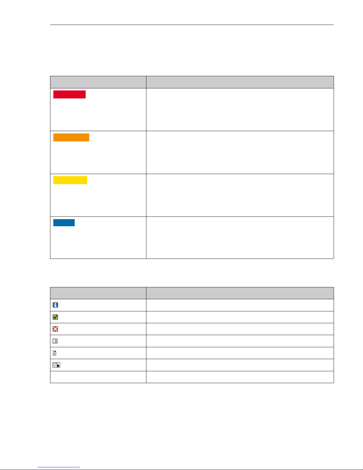
1.1 Warnings
Structure of information Meaning
L
DANGER
Causes (/consequences)
Consequences of non-compliance (if
applicable)
‣
Corrective action
This symbol alerts you to a dangerous situation.
Failure to avoid the dangerous situation will result in a fatal or serious injury.
L
WARNING
Causes (/consequences)
Consequences of non-compliance (if
applicable)
‣
Corrective action
This symbol alerts you to a dangerous situation.
Failure to avoid the dangerous situation can result in a fatal or serious injury.
L
CAUTION
Causes (/consequences)
Consequences of non-compliance (if
applicable)
‣
Corrective action
This symbol alerts you to a dangerous situation.
Failure to avoid this situation can result in minor or more serious injuries.
NOTICE
Cause/situation
Consequences of non-compliance (if
applicable)
‣
Action/note
This symbol alerts you to situations which may result in damage to property.
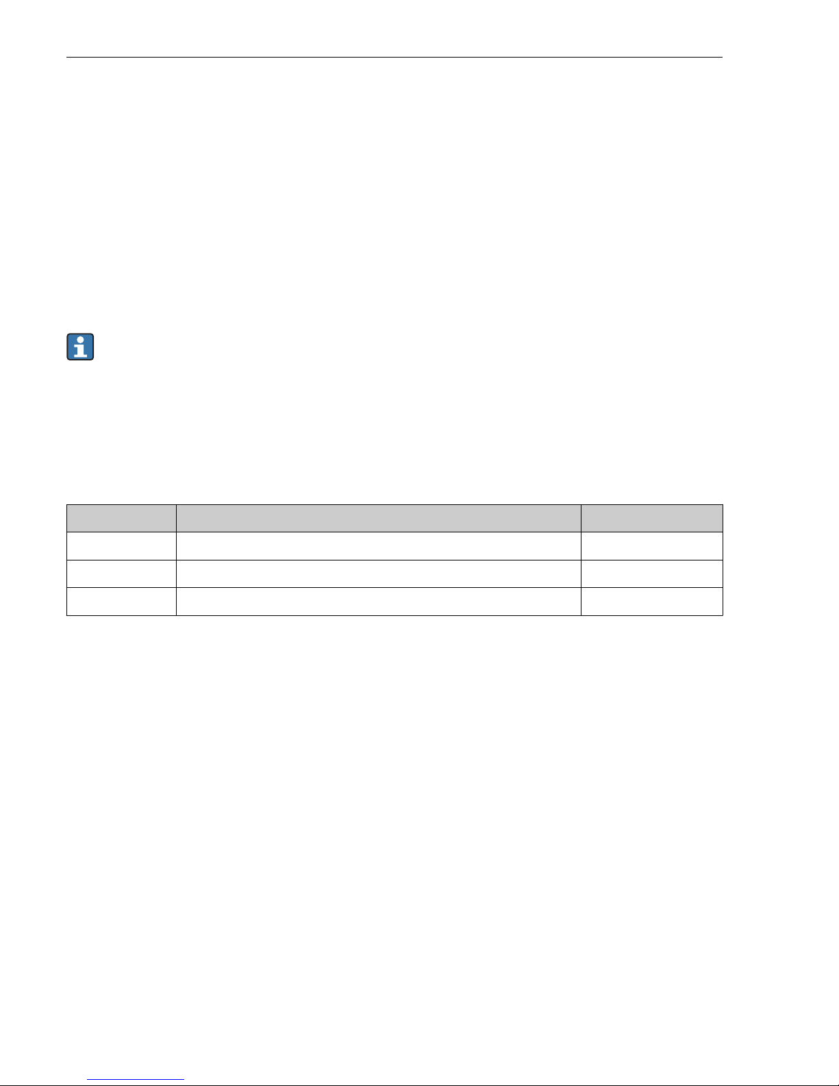
1.2 Symbols
Symbol Meaning
Additional information, tips
Permitted or recommended
Not permitted or not recommended
Reference to device documentation
Reference to page
Reference to graphic
Result of a step
Page 4
Basic safety instructions Condumax CLS15/16/21
4 Endress+Hauser
2 Basic safety instructions
2.1 Requirements for personnel
• Installation, commissioning, operation and maintenance of the measuring system may be
carried out only by specially trained technical personnel.
• The technical personnel must be authorized by the plant operator to carry out the specified
activities.
• The electrical connection may be performed only by an electrical technician.
• The technical personnel must have read and understood these Operating Instructions and
must follow the instructions contained therein.
• Measuring point faults may be repaired only by authorized and specially trained personnel.
Repairs not described in the Operating Instructions provided may only be carried out
directly by the manufacturer or by the service organization.
2.2 Designated use
The conductivity sensors are designed for the conductive measurement of the conductivity of
liquids.
They are used in the following fields:
Sensor Applications Hazardous areas
Condumax CLS15 Measurements in pure and ultrapure water Approved for Ex zone 0
Condumax CLS16 Measurements in pure and ultrapure water with hygienic requirements Approved for Ex zone 0
Condumax CLS21 Measurements in media with medium or high conductivity Approved for Ex zone 0
Use of the device for any purpose other than that described, poses a threat to the safety of
people and of the entire measuring system and is therefore not permitted.
The manufacturer is not liable for damage caused by improper or non-designated use.
2.3 Occupational safety
As the user, you are responsible for complying with the following safety conditions:
• Installation guidelines
• Local standards and regulations
• Regulations for explosion protection
Electromagnetic compatibility
• The product has been tested for electromagnetic compatibility in accordance with the
applicable European standards for industrial applications.
• The electromagnetic compatibility indicated applies only to a product that has been
connected in accordance with these Operating Instructions.
Page 5

Condumax CLS15/16/21 Basic safety instructions
Endress+Hauser 5
2.4 Operational safety
1. Before commissioning the entire measuring point, verify that all connections are
correct. Ensure that electrical cables and hose connections are undamaged.
2. Do not operate damaged products, and safeguard them to ensure that they are not
operated inadvertently. Label the damaged product as defective.
3. If faults cannot be rectified:
Take the products out of operation and safeguard them to ensure that they are not
operated inadvertently.
2.5 Product safety
2.5.1 State of the art
The product is designed to meet state-of-the-art safety requirements, has been tested, and
left the factory in a condition in which it is safe to operate. The relevant regulations and
European standards have been observed.
2.5.2 Electrical equipment in hazardous areas
ATEX/NEPSI II 1G Ex ia IIC T3/T4/T6 Ga
• The sensors CLS15 / CLS16 / CLS21 have been developed and manufactured in compliance
with applicable European standards and guidelines and are suitable for use in hazardous
areas. The EC type examination certificate confirms compliance with the harmonized
European standards for using the sensors in hazardous areas. The corresponding EU
declaration of conformity is part of this document.
• The sensors may only be operated on suitable intrinsically safe circuits. Make sure that the
maximal permissible sensor input characteristic values, the maximum permissible
inductance Li and capacitance values Ci in these circuits and the ambient temperature
ranges indicated are not exceeded.
• The electrical connection must be made according to the wiring diagram of the transmitter.
• Metallic process connection parts must be mounted at the mounting location
electrostatically conductive (< 1 MΩ).
• The CLS15-type sensors with non-metal process connections and the CLS21-type sensors
may only be employed for measurement in liquids with a minimum conductivity of
10 nS/cm.
• The CLS15-type sensors with non-metal process connections may not be operated under
process conditions in which electrostatic charging of the sensor, and particularly of the
electrically insulated outer electrode, is likely to occur.
• The maximum permissible cable length is limited by the maximum permissible
characteristic values of the transmitter: the total of the maximum permissible inductance L
i
and capacitance values Ci for the sensor and measuring cable may not exceed the maximum
permissible inductance Lo and capacitance values Co for the transmitter.
• When connected to the Mycom S CLM153 transmitter, the maximum permissible length of
measuring cables CYK71/CYK71-Ex or CPK9 is 16 m. When connected to the Liquiline M
CM42 transmitter, the maximum length is 50 m.
• Full compliance with regulations for electrical systems in hazardous areas (e.g. EN/IEC
60079-14) is mandatory when using the devices and sensors.
Page 6
Basic safety instructions Condumax CLS15/16/21
6 Endress+Hauser
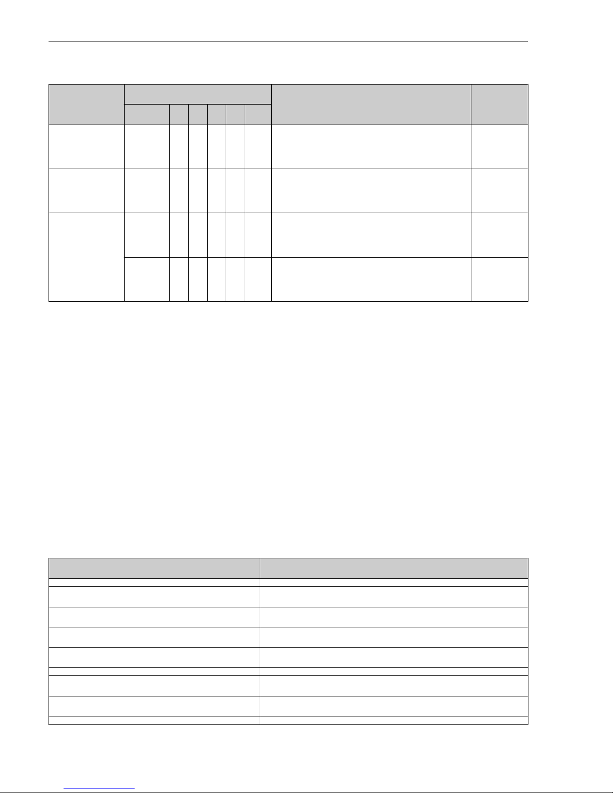
Temperature classes
Name Type Medium temp. Ta for temperature class (Tn) Cat.
x1 x2 x3 x4
Condumax CLS15 - * ** * A -20 °C ≤ Ta ≤ +140 °C (T3)
-20 °C ≤ Ta ≤ +115 °C (T4)
-20 °C ≤ Ta ≤ +65 °C (T6)
II 1G
Condumax CLS16 - X ** * A/B -5 °C ≤ Ta ≤ +150 °C (T3)
-5 °C ≤ Ta ≤ +115 °C (T4)
-5 °C ≤ Ta ≤ +65 °C (T6)
II 1G
Condumax CLS21 - * ** * D -20 °C ≤ Ta ≤ +135 °C (T3)
-20 °C ≤ Ta ≤ +130 °C (T4)
-20 °C ≤ Ta ≤ +80 °C (T6)
II 1G
CLS21 - * ** * A -20 °C ≤ Ta ≤ +135 °C (T3)
-20 °C ≤ Ta ≤ +115 °C (T4)
-20 °C ≤ Ta ≤ +65 °C (T6)
II 1G
X ... Variant not applicable
x1 ... Measuring range and cell constant (no Ex relevance)
x2 ... Process connection / material (no Ex relevance)
x3 ... Measuring cable connection
x4 ... Temperature sensor: A = Pt 100, B = Pt 1000, D = without temperature sensor
• If the specified medium temperatures are complied with, temperatures that are not
permitted for the respective temperature class will not occur on the equipment.
• With the exception of sensor version CLS15-*1M**, for functional reasons the CLS15
sensors may only be operated up to 120 °C (248 °F) during continuous operation / and up to
140 °C (284 °F) for short periods. The CLS15-*1M** version may only be operated up to
100 °C (212 °F) during continuous operation.
• For functional reasons, the CLS16 sensors may only be operated up to 120 °C (248 °F)
during continuous operation / and up to 150 °C (302 °F) for short periods.
The following connection values are safety limits which may not be exceeded when connecting
to the transmitter:
Parameters Connection data
Supply circuit Intrinsically safe
Maximum input voltage U
i
15 V
Maximum input current I
i
30 mA
Maximum input power P
i
130 mW
Maximum internal capacitance C
i
Negligible
Maximum internal inductance L
i
Negligible
Page 7

Condumax CLS15/16/21 Incoming acceptance and product identification
Endress+Hauser 7
Parameters Connection data
Measuring cable CPK9 / CYK71
Maximum internal capacitance C
i
1 nF/m
Maximum internal inductance L
i
6 µH/m
FM/CSA IS/NI Cl.1 Div.1&2 Gr. A-D
Observe the documentation and the control drawings of the transmitter.
3 Incoming acceptance and product identification
3.1 Incoming acceptance
1. Verify that the packaging is undamaged.
Notify your supplier of any damage to the packaging.
Keep the damaged packaging until the matter has been settled.
2. Verify that the contents are undamaged.
Notify your supplier of any damage to the delivery contents.
Keep the damaged products until the matter has been settled.
3. Check the delivery for completeness.
Check it against the delivery papers and your order.
4. Pack the product for storage and transportation in such a way that it is protected
against impact and moisture.
The original packaging offers the best protection.
The permitted ambient conditions must be observed (see "Technical data").
If you have any questions, please contact your supplier or your local sales center.
3.2 Product identification
3.2.1 Nameplate
The nameplate provides you with the following information on your device:
• Manufacturer identification
• Extended order code
• Serial number
• Safety information and warnings
• Cell constant (nominal value)
• Protection class
• Ex labeling on hazardous area versions
‣
Compare the data on the nameplate with your order.
Page 8

Incoming acceptance and product identification Condumax CLS15/16/21
8 Endress+Hauser
3.2.2 Product identification
Product page
www.endress.com/cls15
www.endress.com/cls16
www.endress.com/cls21
Interpreting the order code
The order code and serial number of your product can be found in the following locations:
• On the nameplate
• In the delivery papers
Obtaining information on the product
1. Go to the product page for your product on the Internet.
2. At the bottom of the page, select the "Online Tools" link followed by "Check your device
features".
An additional window opens.
3. Enter the order code from the nameplate into the search field, and then select "Show
details".
You will receive information on each feature (selected option) of the order code.
Manufacturer's address
Endress+Hauser Conducta GmbH+Co. KG
Dieselstraße 24
D-70839 Gerlingen
3.3 Scope of delivery
The scope of delivery includes:
• Sensor in the version ordered
• Cable connector, for connecting to CYK71 measuring cable (only for plug-in head versions
CLS15 CLS21)
• Operating Instructions
3.4 Certificates and approvals
3.4.1
mark
Declaration of conformity
The product meets the requirements of the harmonized European standards. As such, it
complies with the legal specifications of the EU directives. The manufacturer confirms
successful testing of the product by affixing to it the mark.
Page 9

Condumax CLS15/16/21 Incoming acceptance and product identification
Endress+Hauser 9
3.4.2 Hazardous area approvals
ATEX II 1G Ex ia IIC T3/T4/T6 Ga
FM/CSA IS/NI Cl. I Div.1&2 Gr. A-D in conjunction with Liquiline M CM42 transmitter
3.4.3 EHEDG (CLS16 only)
Validated as follows:
• Cleanability in accordance with EHEDG, Document 2
• Sterilizability in accordance with EHEDG, Document 5
• Bacteria-tightness in accordance with EHEDG, Document 7
3.4.4 FDA (CLS16 only)
All materials in contact with the product are listed by the FDA.
3.4.5 Manufacturer inspection certificate
Stating the individual cell constant
3.4.6 Biological reactivity test (USP class VI, CLS16 only)
Biological reactivity test certificate according to USP (United States Pharmacopeia)part <87>
and part <88> class VI with batch traceability of materials in contact with the medium
3.4.7 Inspection certificate in accordance with EN 10204 3.1
A test certificate 3.1 in accordance with EN10204 is supplied depending on the version (→
Product Configurator on the product page).
3.4.8 ASME (CLS16 only)
Manufactured in accordance with ASME criteria (American Society of Mechanical Engineers)
3.4.9 Ex-certification body
TÜV Rheinland Industrie Service GmbH
Cologne
Page 10

Installation Condumax CLS15/16/21
10 Endress+Hauser
4 Installation
4.1 Mounting the sensor
4.1.1 CLS15
The sensors are installed directly via the process connection thread NPT ½" or ¾" or
clamp 1 ½". As an option, the sensor can also be installed using a commercially available Tpiece or cross fitting or using a flow assembly.
NOTICE
Incorrect mounting or disassembly
The sensor head could become loose and fall off, resulting in total sensor failure
‣
Only mount the sensor via the process connection.
‣
To do so, use a suitable tool, such as an open-ended wrench.
Page 11

Condumax CLS15/16/21 Installation
Endress+Hauser 11
2
1
3
35 (1.38)
A0024199
1 With NPT ½" thread in T-piece or cross
fitting
1 T-piece or cross fitting (DN 32, 40 or 50)
2 Glue-in VC threaded coupling (NPT ½" for
DN 20)
3 Glue-in adapter coupling (for DN 32, 40, 50)
½”NPT
160 (6.30)
Ø 29 (1.14)
Ø 6 (0.24)
30 (1.18)
25 (0.98)
Ø 6 (0.24)
38.5
(1.52)
1
2
3
A0024200
2 With NPT ½" thread in flow assembly
71042405, dimensions in mm (inch)
1 Sensor holder NPT ½"
2 Inlet
3 Outlet
Ensure that the electrodes are fully immersed in the medium during measurement. The
immersion depth must be at least 35 mm (1.38"). If the sensor is being used in the
ultrapure water range, you must work under air-evacuated conditions. Otherwise the CO
2
in the air can dissolve in the water and its (weak) dissociation can increase the
conductivity by up to 3 µS/cm.
Page 12

Installation Condumax CLS15/16/21
12 Endress+Hauser
4.1.2 CLS16
The sensors are installed directly via the process connection. Take the flow direction into
consideration when installing in pipes.
A0024198
3 Permitted flow direction
A0024197
4 Inadmissible flow direction
Ensure that the electrodes are fully immersed in the medium during measurement. If the
sensor is being used in the ultrapure water range, you must work under air-evacuated
conditions. Otherwise the CO2 in the air can dissolve in the water and its (weak)
dissociation can increase the conductivity by up to 3 µS/cm.
4.1.3 CLS21
Clamp connection
Both sheet-metal brackets and solid brackets can be used to secure the sensor. Sheetmetal brackets have a lower dimensional stability, uneven bearing surfaces causing point
loads, and sometimes sharp edges that can damage the clamp. We recommend you only
use solid brackets due to their higher dimensional stability. Solid brackets can be used
over the entire pressure/temperature range (see pressure-temperature ratings).
Page 13

Condumax CLS15/16/21 Installation
Endress+Hauser 13
The sensors are installed directly via the process connection. As an option, the sensor can also
be installed via a flow assembly.
NOTICE
Incorrect mounting or disassembly
The sensor head could become loose and fall off, resulting in total sensor failure
‣
Only mount the sensor via the process connection.
‣
To do so, use a suitable tool, such as an open-ended wrench.
A0024201
5 Installation in flow assembly CLA751
A0024202
6 Installation in flow assembly CLA752
Page 14

Electrical connection Condumax CLS15/16/21
14 Endress+Hauser
The Dipfit CLA111 immersion assembly is available to install sensors with a G1 thread in
vessels.
A B
D
A0024145
7 Installation in Dipfit CLA111 immersion assembly, fastening versions A, B and D
Ensure that the electrodes are fully immersed in the medium during measurement.
4.2 Post-installation check
• Are the sensor and cable undamaged?
• Is the sensor installed in the process connection and is not suspended from the cable?
5 Electrical connection
L
WARNING
Device is live
Incorrect connection may result in injury or death
‣
The electrical connection may be performed only by an electrical technician.
‣
The electrical technician must have read and understood these Operating Instructions and
must follow the instructions contained therein.
‣
Prior to commencing connection work, ensure that no voltage is present on any cable.
Page 15

Condumax CLS15/16/21 Electrical connection
Endress+Hauser 15
5.1 Connection conditions
5.1.1 Connection at a glance
CPS11
CPS12
CPS71
CPS72
CPS91
CPS13
CPS64
EX
Ex ia Ga
CPS41
CPS42
Ex ia Ga
EX
CLS50
CPS471
CPS491
CPS441
CLS54
CLS12
CLS13 CLS15 CLS16 CLS21
IIC 2G
IIC 1G
IIC 3G
Zone 1
Zone 0
Zone 2
A0031175
8 Electrical connection in hazardous areas
Page 16

Electrical connection Condumax CLS15/16/21
16 Endress+Hauser
5.2 Connecting the sensor
5.2.1 CLS15 and CLS21
The sensor is connected via the fixed cable or via the CYK71 measuring cable with a shield.
The wiring diagram is provided in the Operating Instructions of the transmitter used.
GN/YE
Outer shield
(see wiring diagram
of transmitter)
YE
GN
WH
Pt 100
Coax BK
Coax inner
shield (outer electrode)
BN n.c.
conductivity (inner electrode)
}
Cable
}
GY
Sensor
Plug
2
3
1
)
A0024205-EN
9 Measuring cable CYK71
A compatible cable connector is included in the delivery for the plug-in head versions. You
must terminate the CYK71 cable (not included in the delivery) with the cable connector at the
sensor end according to the connection diagram above.
A VMB junction box and another CYK71 cable are required for the cable extension.
5.2.2 CLS16
The sensor is electrically connected via the CPK9 measuring cable (plug-in head versions) or
the sensor's fixed cable. The wiring diagram is provided in the Operating Instructions of the
transmitter used.
Outer electrode
Inner electrode
BN
n.c.
BK
WH
GN
WH
YE
Temp.
Temp.
Temp.
GY
Outer shield
(see wiring diagram
of transmitter)
A0024206-EN
10 Measuring cable CPK9
A VMB junction box and a CYK71 cable are required for the cable extension.
Page 17

Condumax CLS15/16/21 Commissioning
Endress+Hauser 17
5.3 Ensuring the degree of protection
Only the mechanical and electrical connections which are described in these instructions and
which are necessary for the required, designated use, may be carried out on the device
delivered.
‣
Exercise care when carrying out the work.
Otherwise, the individual types of protection (Ingress Protection (IP), electrical safety, EMC
interference immunity) agreed for this product can no longer be guaranteed due, for example,
to covers being left off or cable (ends) which are loose or insufficiently secured.
5.4 Post-connection check
Device condition and specifications Notes
Are the outside of the sensor, assembly, cable undamaged? Visual inspection
Electrical connection Notes
Are the installed cables strain-relieved and not twisted?
Is a sufficient length of the cable cores stripped, and is it positioned
in the terminal correctly?
Check the fit (by pulling gently)
Are all the screws terminals properly tightened? Tighten
Are all cable entries mounted, tightened and leak-tight? For lateral cable entries, make sure the cables
loop downwards to allow water to drip off
Are all cable entries installed downwards or mounted laterally?
6 Commissioning
Before first commissioning, check if:
• the sensor is correctly installed
• the electrical connection is correct.
If using an assembly with automatic cleaning, check that the cleaning medium (e.g. water or
air) is connected correctly.
L
WARNING
Escaping process medium
Risk of injury from high pressure, high temperatures or chemical hazards
‣
Before applying compressed air to an assembly with cleaning facility, make sure the
connections are correctly fitted.
‣
Do not install the assembly in the process if you cannot make the correct connection
reliably.
Page 18

Maintenance Condumax CLS15/16/21
18 Endress+Hauser
7 Maintenance
L
CAUTION
Corrosive chemicals
Danger of chemical burns to the eyes and skin. Danger of damage to clothing and equipment
‣
It is absolutely essential to protect the eyes and hands properly when working with acids,
bases and organic solvents!
‣
Wear protective goggles and safety gloves.
‣
Clean away splashes on clothes and other objects to prevent any damage.
‣
Pay particular attention to the information provided in the safety data sheets for the
chemicals used.
L
WARNING
Hydrofluoric acid and mineral acids
Risk of serious or fatal injury from caustic burns
‣
Wear protective goggles to protect your eyes.
‣
Wear protective gloves and appropriate protective clothing.
‣
Avoid all contact with the eyes, mouth and skin.
‣
If using hydrofluoric acid, only use plastic vessels.
L
WARNING
Thiocarbamide
Harmful if swallowed. Limited evidence of carcinogenicity. Possible risk of harm to the unborn
child. Dangerous for the environment with long-term effects.
‣
Wear protective goggles, protective gloves and appropriate protective clothing.
‣
Avoid all contact with the eyes, mouth and skin.
‣
Avoid releases into the environment.
Clean away fouling on the sensor as follows depending on the type of fouling:
1. Oily and greasy films:
Clean with grease remover, e.g. alcohol, as well as hot water and (alkaline) agents
containing surfactants (e.g. dishwashing detergent).
2. Lime, cyanide and metal hydroxide buildup and low solubility organic buildup:
Dissolve buildup with diluted hydrochloric acid (3 %) and then rinse thoroughly with
plenty of clear water.
3. Sulfidic buildup (from flue gas desulfurization or sewage treatment plants):
Use a mixture of hydrochloric acid (3 %) and thiocarbamide (commercially available)
and then rinse thoroughly with plenty of clear water.
4. Buildup containing proteins (e.g. food industry):
Use a mixture of hydrochloric acid (0.5 %) and pepsin (commercially available) and then
rinse thoroughly with plenty of clear water.
Page 19

Condumax CLS15/16/21 Repair
Endress+Hauser 19
5. Readily soluble biological buildup:
Rinse with pressurized water.
After cleaning or regeneration, you must rinse the sensor thoroughly with water and
then recalibrate it.
8 Repair
8.1 Sealing ring replacement and recalibration (CLS16 only)
Intact seals are a prerequisite for safe and reliable measurements. The seal should be replaced
at regular intervals to guarantee maximum sensor operational safety and hygiene.
Practical repair intervals can only be determined by the user as they depend greatly on the
operating conditions, such as:
• Type and temperature of the product
• Type and temperature of the cleaning agent
• Number of cleanings
• Number of sterilizations
• Operating environment
Recommended intervals for seal replacement (reference values)
Application Window
Media with temperatures from 50 to 100 °C (122 to 212 °F) Approx. 18 months
Media with temperatures < 50 °C (122 °F) Approx. 36 months
Sterilization cycles, max. 150 °C (302 °F), 45 min. Approx. 400 cycles
To ensure your sensor is operational again after being exposed to very high loads, you can
have it regenerated in the factory. In the factory, the sensor is fitted with new seals and
recalibrated.
Please contact your sales office for information on replacing the seal and recalibration in the
factory.
8.2 Return
The product must be returned if repairs or a factory calibration are required, or if the wrong
product was ordered or delivered. As an ISO-certified company and also due to legal
regulations, Endress+Hauser is obliged to follow certain procedures when handling any
returned products that have been in contact with medium.
To ensure swift, safe and professional device returns, please read the return procedures and
conditions at www.endress.com/support/return-material.
Page 20

Repair Condumax CLS15/16/21
20 Endress+Hauser
8.3 Disposal
The device contains electronic components and must therefore be disposed of in accordance
with regulations on the disposal of electronic waste.
Observe the local regulations.
Page 21

Condumax CLS15/16/21 Technical data
Endress+Hauser 21
9 Technical data
9.1 Input
9.1.1 Measured values
• Conductivity
• Temperature
9.1.2 Measuring ranges
Conductivity (in relation to water at 25 °C (77 °F))
CLS15-A 0.04 to 20 μS/cm
CLS15-B/L 0.10 to 200 μS/cm
CLS16 0.04 to 500 μS/cm
CLS21 10 μS/cm to 20 mS/cm
Temperature
CLS15 -20 to 140 °C (-4 to 280 °F)
CLS16 -5 to 150 °C (23 to 300 °F)
CLS21 -20 to 135 °C (-4 to 275 °F)
9.1.3 Cell constant
CLS15-A
k = 0.01 cm
–1
CLS15-B/L k = 0.1 cm
–1
CLS16 k = 0.1 cm
–1
CLS21 k = 1.0 cm–1, nominal
9.1.4 Temperature compensation
Pt 100 (class A as per IEC 60751) (CLS15) (CLS16) (CLS21)
Pt 1000 (class A as per IEC 60751)(CLS16, optional)
Page 22

Technical data Condumax CLS15/16/21
22 Endress+Hauser
9.2 Performance characteristics
9.2.1 Uncertainty of measurement
CLS15
Each individual sensor is factory-measured in a solution of approx. 5 μS/cm for cell constant
0.01 cm-1 or approx. 50 μS/cm for cell constant 0.1 cm-1 using a reference measuring system
traceable to NIST or PTB. The exact cell constant is entered into the quality certificate
supplied. The uncertainty of measurement in determining the cell constant is 1.0 %.
CLS16
Each individual sensor is factory-measured in a solution of approx. 5 μS/cm using a reference
measuring system traceable to NIST or PTB. The exact cell constant is entered into the quality
certificate supplied. The uncertainty of measurement in determining the cell constant is
1.0 %.
CLS21
Each individual sensor is factory-measured in a solution of approx. 500 µS/cmusing a
reference measuring system traceable to NIST or PTB. The exact cell constant is entered into
the quality certificate supplied. The uncertainty of measurement in determining the cell
constant is 1.0 %.
Page 23

Condumax CLS15/16/21 Technical data
Endress+Hauser 23
9.3 Environment
9.3.1 Ambient temperature range
-20 to +60 °C (-4 to 140 °F)
9.3.2 Storage temperature
-25 to +80 °C (-10 to +180 °F)
9.3.3 Degree of protection
CLS15 IP 67 / NEMA 6
CLS16
Fixed cable version IP 67 / NEMA 6
TOP68 plug-in system IP 68 / NEMA 6
CLS21
Fixed cable version IP 67 / NEMA 6
Plug-in head version IP 65 / NEMA 4X
9.4 Process
9.4.1 Process temperature
CLS15
Threaded version with fixed cable -20 to 100 °C (-4 to 212 °F)
Threaded version with plug-in head, Clamp version
Normal operation -20 to 120 °C (-4 to 248 °F)
Sterilization (max. 1 h)
1)
Max. 140 °C (284 °F)
CLS16
Normal operation -5 to 120 °C (23 to 248 °F)
Sterilization (max. 45 min) Max. 150 °C (302 °F) at 6 bar (87 psi) absolute
CLS21
Threaded version with fixed cable -20 to 100 °C (-4 to 212 °F)
Version with plug-in head, Clamp version-20 to +135 °C (-4 to 275 °F) at 3.5 bar (50 psi)
absolute
1) Threaded versions: max. 30 minutes
Page 24

Technical data Condumax CLS15/16/21
24 Endress+Hauser
9.4.2 Process pressure
CLS15 13 bar (188 psi) absolute, at 20 °C (68 °F)
2 bar (29 psi) absolute, at 120 °C (248 °F)
CLS16 13 bar (188 psi) absolute, at 20 °C (68 °F)
9 bar (130 psi) absolute, at 120 °C (248 °F)
0.1 bar (1.5 psi) absolute (negative pressure), at
20 °C (68 °F)
CLS21 17 bar (246 psi) absolute, at 20 °C (68 °F)
9.4.3 Temperature/pressure ratings
CLS15
A
14010060
68
20
-4
180 220 260
248
284
–20
0 20 40 60 80 100 120 140
B
212
[psi]
[° ]F
[bar]
[°C]
p (abs.)
T
14
43
72
188
1
3
5
7
9
11
13
A0031429-EN
11 Mechanical pressure-temperature resistance
A Can be sterilized for a short time (1 hour)
B Threaded version with fixed cable
Page 25

Condumax CLS15/16/21 Technical data
Endress+Hauser 25
CLS16
6
–5
20 60 100 120 150
23
60
68
120
180
240
248
300
20 60 100 120 150
302
A
[° ]F
[bar]
[°C]
p (abs.)
T
14
43
72
101
130
159
188
1
3
5
7
9
11
13
87
1.5 0.1
A0031431-EN
12 Mechanical pressure-temperature resistance
A Can be sterilized for a short time (45 min.)
CLS21
5
9
13
17
300 60 90 120
[°C]
-4
1
10060 140 180 220
72
130
188
-20
14
[°F]
20
68 275
246
[psi]
[bar]
3.5
51
135
p (abs.)
T
20
A0031435-EN
13 Mechanical pressure-temperature resistance
9.5 Mechanical construction
9.5.1 Weight
CLS15 and CLS21
Approx. 0.3 kg (0.66 lbs) depending on version
Page 26

Technical data Condumax CLS15/16/21
26 Endress+Hauser
CLS16
Approx. 0.13 to 0.75 kg (0.29 to 1.65 lbs) depending on version
9.5.2 Materials
CLS15
Electrodes Polished, stainless steel 1.4435 (AISI 316L)
Sensor shaft Polyethersulfone (PES-GF20)
O-ring, in contact with medium
(only Clamp version)
EPDM
CLS16
Electrodes Electropolished, stainless steel 1.4435 (AISI 316L)
Seal Gasket seal ISOLAST (FFKM), FDA-compliant
CLS21
Electrodes Graphite
Sensor shaft Polyethersulfone (PES-GF20)
Thermal conductivity socket for
temperature probe
Titanium 3.7035
9.5.3 Process connection
CLS15
Thread NPT ½" and ¾"
Clamp 1½" as per ISO 2852
CLS16
Clamp 1", 1½", 2" as per ISO 2852 (also suitable for TRI-CLAMP, DIN 32676)
Tuchenhagen VARIVENT N DN 50 to 125
NEUMO BioControl D50
CLS21
Thread G1
NPT 1" thread
Clamp 2" as per ISO 2852
Sanitary connection DN 25 as per DIN 11851
9.5.4 Surface roughness (CLS15, CLS16 only)
CLS15
Ra ≤ 0.8 μm
CLS16
Ra ≤ 0.8 μm, electropolished
Ra ≤ 0.38 μm, electropolished, optional
Page 27

Condumax CLS15/16/21 EU Declaration of conformity
Endress+Hauser 27
10 EU Declaration of conformity
Page 28

www.addresses.endress.com
*71337736*
71337736
 Loading...