

Endress+Hauser COA451 Operating Manual
BA00368C/07/EN/14.20
71478861
2020-04-17
Products Solutions Services
Operating Instructions
Cleanfit COA451
Retractable process assembly


Cleanfit COA451 Table of contents
Table of contents
1 About this document ........... 4
1.1 Warning sign ........................ 4
1.2 Symbols used ........................ 4
1.3 Symbols on the device ................ 5
2 Basic safety instructions ....... 5
2.1 Requirements for personnel ........... 5
2.2 Designated use ...................... 5
2.3 Workplace safety .................... 5
2.4 Operational safety ................... 6
2.5 Product safety ....................... 6
3 Product description ............. 7
3.1 Product design ....................... 7
4 Incoming acceptance and
product identification .......... 9
4.1 Incoming acceptance ................. 9
4.2 Product identification ................ 10
4.3 Scope of delivery .................... 10
4.4 Certificates and approvals ............ 11
5 Installation .................... 12
5.1 Installation conditions ............... 12
5.2 Mounting the assembly .............. 20
5.3 Post-installation check ............... 33
10.3 Accessory kits ...................... 49
11 Technical data ................. 50
11.1 Environment ....................... 50
11.2 Process ............................ 50
11.3 Mechanical construction ............. 50
Index ................................. 52
6 Commissioning ................ 34
6.1 Function check ..................... 34
7 Operation ...................... 35
7.1 Adapting the device to the process
conditions ......................... 35
8 Maintenance .................. 36
8.1 Maintenance tasks .................. 36
9 Repair .......................... 43
9.1 General notes ...................... 43
9.2 Spare parts ........................ 44
9.3 Return ............................ 46
9.4 Disposal .......................... 46
10 Accessories .................... 46
10.1 Device-specific accessories ............46
10.2 Service-specific accessories ........... 49
Endress+Hauser 3
About this document Cleanfit COA451
1 About this document
1.1 Warning sign
Structure of information Meaning
DANGER
L
Causes (/consequences)
If necessary, Consequences of noncompliance (if applicable)
Corrective action
‣
WARNING
L
Causes (/consequences)
If necessary, Consequences of noncompliance (if applicable)
Corrective action
‣
CAUTION
L
Causes (/consequences)
If necessary, Consequences of noncompliance (if applicable)
Corrective action
‣
NOTICE
Cause/situation
If necessary, Consequences of noncompliance (if applicable)
Action/note
‣
This symbol alerts you to a dangerous situation.
Failure to avoid the dangerous situation will result in a fatal or serious injury.
This symbol alerts you to a dangerous situation.
Failure to avoid the dangerous situation can result in a fatal or serious injury.
This symbol alerts you to a dangerous situation.
Failure to avoid this situation can result in minor or more serious injuries.
This symbol alerts you to situations which may result in damage to property.
1.2 Symbols used
Symbol Meaning
Additional information, tips
Permitted or recommended
Not permitted or not recommended
Reference to device documentation
Reference to page
Reference to graphic
Result of a step
4 Endress+Hauser
Cleanfit COA451 Basic safety instructions
1.3 Symbols on the device
Symbol Meaning
Reference to device documentation
2 Basic safety instructions
2.1 Requirements for personnel
• Installation, commissioning, operation and maintenance of the measuring system may be
carried out only by specially trained technical personnel.
• The technical personnel must be authorized by the plant operator to carry out the specified
activities.
• The electrical connection may be performed only by an electrical technician.
• The technical personnel must have read and understood these Operating Instructions and
must follow the instructions contained therein.
• Faults at the measuring point may only be rectified by authorized and specially trained
personnel.
Repairs not described in the Operating Instructions provided must be carried out only
directly at the manufacturer's site or by the service organization.
2.2 Designated use
The manually operated Cleanfit COA451 retractable assembly is designed for the installation
of oxygen sensors in vessels and pipelines. Their mechanical construction means that they can
be operated in pressurized systems (see technical data).
The assembly is designed exclusively for use in liquid media.
Use of the device for any purpose other than that described, poses a threat to the safety of
people and of the entire measuring system and is therefore not permitted.
The manufacturer is not liable for damage caused by improper or non-designated use.
2.3 Workplace safety
As the user, you are responsible for complying with the following safety conditions:
• Installation guidelines
• Local standards and regulations
Electromagnetic compatibility
• The product has been tested for electromagnetic compatibility in accordance with the
applicable international standards for industrial applications.
• The electromagnetic compatibility indicated applies only to a product that has been
connected in accordance with these Operating Instructions.
Endress+Hauser 5

Basic safety instructions Cleanfit COA451
2.4 Operational safety
Before commissioning the entire measuring point:
1. Verify that all connections are correct.
2. Ensure that electrical cables and hose connections are undamaged.
3. Do not operate damaged products, and protect them against unintentional operation.
4. Label damaged products as defective.
During operation:
If faults cannot be rectified:
‣
products must be taken out of service and protected against unintentional operation.
CAUTION
L
Cleaning not switched off during calibration or maintenance activities
Risk of injury due to medium or cleaning agent!
If a cleaning system is connected, switch it off before removing a sensor from the medium.
‣
If you wish to check the cleaning function and have therefore not switched off the cleaning
‣
system, wear protective clothing, goggles and gloves or take other appropriate measures.
2.5 Product safety
2.5.1 State-of-the-art technology
The product is designed to meet state-of-the-art safety requirements, has been tested, and
left the factory in a condition in which it is safe to operate. The relevant regulations and
international standards have been observed.
6 Endress+Hauser
Cleanfit COA451 Product description
1
2
3
4
5
6
8
9
7
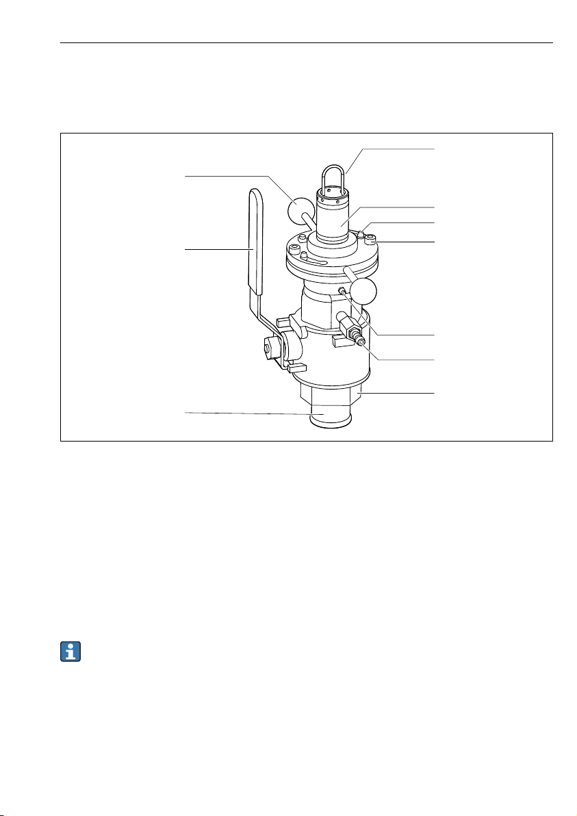
3 Product description
3.1 Product design
A0038438
1 Assembly in operational state (ball valve open)
1 Bracket for sensor holder
2 Sensor holder
3 Bayonet lock
4 Securing screws
5 Grease nipple
6 Ball valve/valve for venting or rinse connection
7 Process connection
8 Retraction pipe
9 Hand lever for opening/closing the ball valve
10 Handles
An additional rinse chamber valve can be mounted in the locking screw opposite the vent
valve.
Endress+Hauser 7
Product description Cleanfit COA451
2
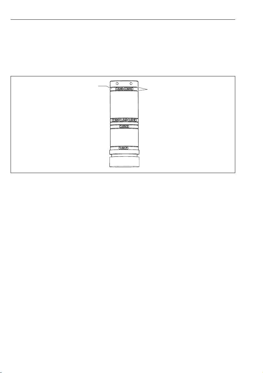
3.1.1 Universal sensor holder
The sensor holder is used to position the sensor correctly in order to ensure correct measuring
accuracy.
If the sensor is not positioned correctly, the ball valve may be blocked or the sensor may be
located in the dead space as a result.
A0038451
2 Short sensor holder
1 Mounting position of the bayonet nut to hold the relevant sensor
2 Grooves of the safety rings to mount the bayonet nut
8 Endress+Hauser

Cleanfit COA451 Incoming acceptance and product identification
A0038479
3 Mounting position of the bayonet nut for CUS65D or COS51D
The name indicated on the holder serves as a mounting aid. The bayonet nut covers over
the marking for the selected sensor position.
4 Incoming acceptance and product identification
4.1 Incoming acceptance
1. Verify that the packaging is undamaged.
Notify the supplier of any damage to the packaging.
Keep the damaged packaging until the issue has been resolved.
2. Verify that the contents are undamaged.
Notify the supplier of any damage to the delivery contents.
Keep the damaged goods until the issue has been resolved.
3. Check that the delivery is complete and nothing is missing.
Compare the shipping documents with your order.
4. Pack the product for storage and transportation in such a way that it is protected
against impact and moisture.
The original packaging offers the best protection.
Make sure to comply with the permitted ambient conditions.
If you have any questions, please contact your supplier or your local Sales Center.
Endress+Hauser 9

Incoming acceptance and product identification Cleanfit COA451
4.2 Product identification
4.2.1 Nameplate
The nameplate provides you with the following information on your device:
• Manufacturer identification
• Order code
• Extended order code
• Operating conditions
• Serial number
• Safety information and warnings
• Approvals as per version ordered
Compare the information on the nameplate with the order.
‣
4.2.2 Identifying the product
Product page
www.endress.com/COA451
Interpreting the order code
The order code and serial number of your product can be found in the following locations:
• On the nameplate
• In the delivery papers
Obtaining information on the product
1. Go to www.endress.com.
2. Call up the site search (magnifying glass).
3. Enter a valid serial number.
4. Search.
The product structure is displayed in a popup window.
5. Click on the product image in the popup window.
A new window (Device Viewer) opens. All of the information relating to your
device is displayed in this window as well as the product documentation.
4.2.3 Manufacturer's address
Endress+Hauser Conducta GmbH+Co. KG
Dieselstraße 24
D-70839 Gerlingen
4.3 Scope of delivery
The delivery comprises:
• Assembly in the version ordered
• Operating Instructions, English.
10 Endress+Hauser

Cleanfit COA451 Incoming acceptance and product identification
If you have any questions, please contact your supplier or your local sales center.
4.4 Certificates and approvals
4.4.1 CE/PED
The assembly has been manufactured according to good engineering practice as per Article 4,
Paragraph 3 of the Pressure Equipment Directive 2014/68/EU and is therefore not required
to bear the CE label.
Endress+Hauser 11
Installation Cleanfit COA451
226 (8.90)
Ø 49.3
(1.94)
X0
100
(3.94)
Ø 46
(1.81)
106
(4.17)
1 (0.04)
X1
311 (12.24)
67
(2.64)
185 (7.28)
270 (10.63)
109.5 (4.31)
92 (3.62)
115.5 (4.55)
Ø 86 (3.39)
Ø 91 (3.58)
X0
5 Installation
5.1 Installation conditions
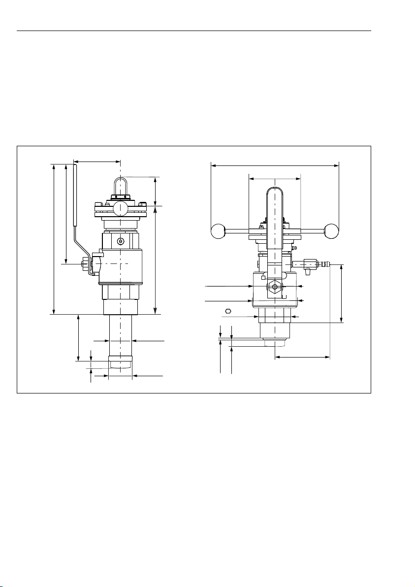
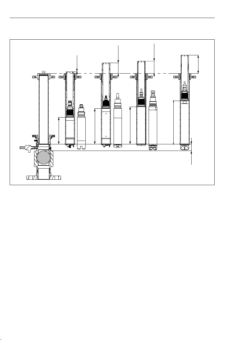
5.1.1 Dimensions
Assembly with G2" thread and weld-in adapter in measuring position (long and short
stroke)
4 Dimensions in mm (in)
X0,X1Dimensions depend on the sensor
12 Endress+Hauser
A0038481

Cleanfit COA451 Installation
101 (3.98)
X2
171
(6.73)
100
(3.94)
32
(1.26)
X2
276 (10.87)
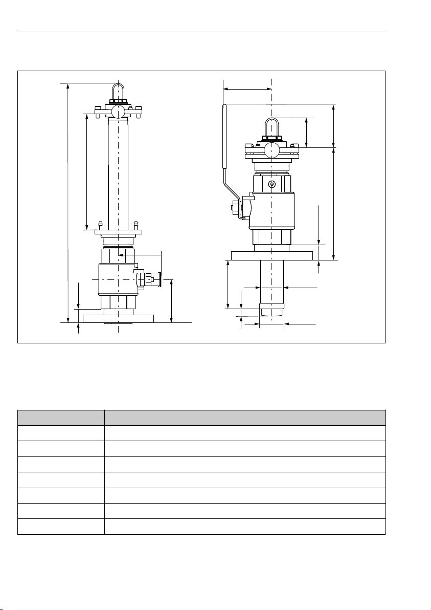
Assembly with G2" thread and weld-in adapter in service position (long and short
stroke)
5 Dimensions in mm (in)
X2 Dimensions depend on the sensor
Endress+Hauser 13
A0038630
Installation Cleanfit COA451
Ø 49.3
(1.94)
Ø 46
106 (4.17)
X0
100
(3.94)
X1
85
(3.35)
32 (1.26)
226 (8.90)
(1.81)
32
(1.26)
X2
276 (10.87)
100
(3.94)
101 (3.98)
Assembly with flange connection
6 Dimensions in mm (in)
X0,X2Dimensions depend on the sensor
Sensor X0
CUS52D 25 (0.98)
CUS50D 26 (1)
CUS41/ 16 (0.63)
CUS51D 5 (0.2)
COS61D 12 (0.47)
CUS65 21 (0.83)
COS51D 12 (0.47)
14 Endress+Hauser
A0038651
Cleanfit COA451 Installation
Sensor measuring
position
CUS52D 139 (5.47)
CUS50D 110 (4.33)
CUS41/CUS51D, COS61D 101 (3.98)
CUS65, COS51D 59 (2.32)
Sensor service position,
long
CUS52D 638 (25.12)
CUS50D 609 (23.98)
CUS41/CUS51D, COS61D 600 (23.62)
CUS65, COS51D 558 (21.97)
Sensor service position,
short
CUS52D 533 (20.98)
CUS50D 504 (19.84)
CUS41/CUS51D, COS61D 495 (19.49)
CUS65, COS51D 453 (17.83)
X1
X2
X2
Endress+Hauser 15
Installation Cleanfit COA451
9.25
(0.37)
51.4
(2.02)
60.2
(2.37)
89.5
(3.52)
COS51D
CUS65(D)
COS61(D)
CUS41(D)
CUS51D
CUS50D
CUS52D
131
(5.16)
173 (6.81)
182 (7.17)
211 (8.31)
32
(1.26)
Sensor holder with sensors
A0038478
7 Dimensions of sensor holder with sensors in mm (in)
16 Endress+Hauser
Cleanfit COA451 Installation
A
2"
32 (1.26)
a
b
B
C
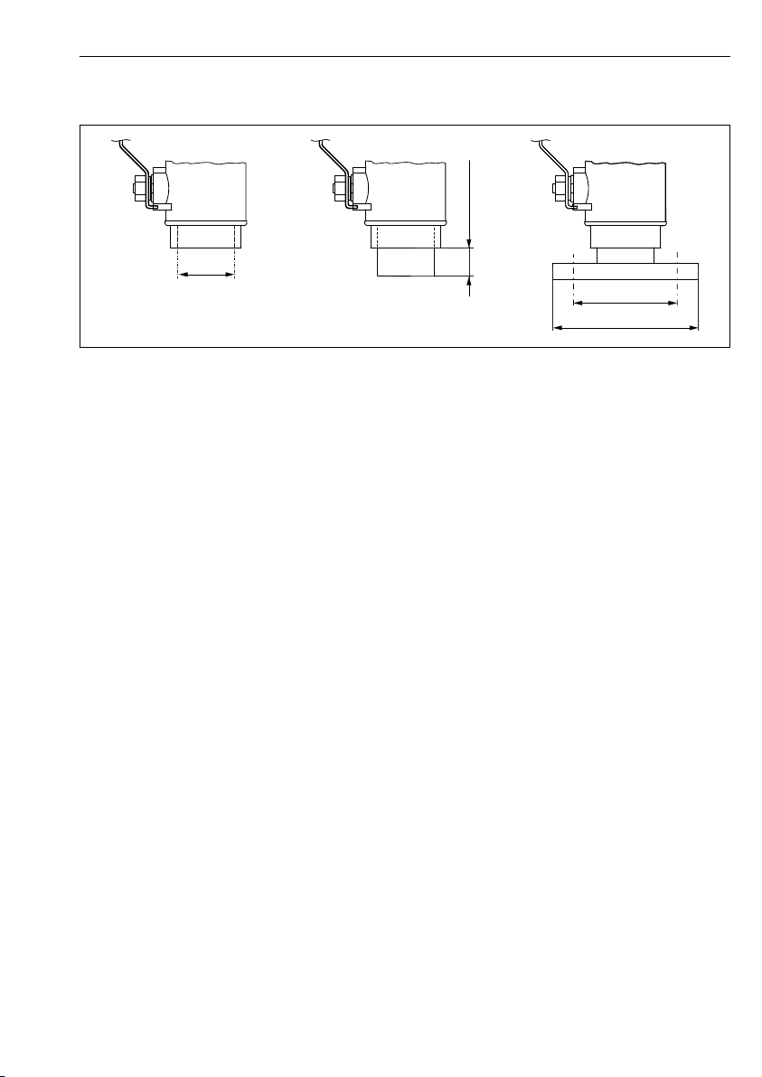
5.1.2 Process connections
A0038650
8 Dimensions of process connections in mm (in)
A G2" female thread
B G2" female thread with weld-in adapter
C Flange DN 50 / PN 16 (as per EN 1092-1) and flange ANSI 2" / 150 lbs
a DN 50: Ø 125 (4.92), ANSI 2": Ø 120.7 (4.75)
b DN 50: Ø 165 (6.50), ANSI 2": Ø 152.4 (6.00)
Endress+Hauser 17
 Loading...