

Page 1
Operating Instructions
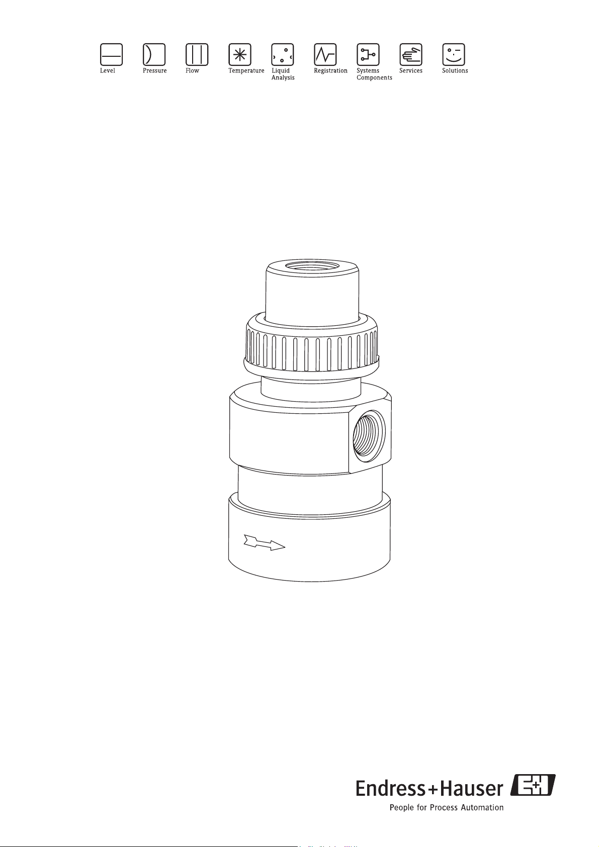
Flowfit W COA250
Flow assembly for oxygen sensors
BA111C/07/en/02.07
51515479
Page 2

Brief overview
Fig. 1: COA250 with Sensor
1 Sensor sleeve
2 Inlet (G¾ thread)
3 Outlet (G¾ thread)
4Union nut D50
5 Oxygen sensor (accessories, not in scope of delivery)
a0007313
Page 3

Table of contents
1 Safety instructions . . . . . . . . . . . . . . . . 4
1.1 Designated use . . . . . . . . . . . . . . . . . . . . . . . . . . . . 4
1.2 Installation, commissioning and operation . . . . . . . . 4
1.3 Operational safety . . . . . . . . . . . . . . . . . . . . . . . . . . 4
1.4 Return . . . . . . . . . . . . . . . . . . . . . . . . . . . . . . . . . . . 5
1.5 Notes on safety icons and symbols . . . . . . . . . . . . . . 5
2 Identification . . . . . . . . . . . . . . . . . . . . 6
2.1 Nameplate . . . . . . . . . . . . . . . . . . . . . . . . . . . . . . . 6
2.2 Product structure . . . . . . . . . . . . . . . . . . . . . . . . . . 6
2.3 Scope of delivery . . . . . . . . . . . . . . . . . . . . . . . . . . . 6
3 Installation . . . . . . . . . . . . . . . . . . . . . . 7
3.1 Incoming acceptance, transport, storage . . . . . . . . . . 7
3.2 Installation conditions . . . . . . . . . . . . . . . . . . . . . . . 7
3.3 Installation instructions . . . . . . . . . . . . . . . . . . . . . . 9
3.4 Post-installation check . . . . . . . . . . . . . . . . . . . . . . 11
4 Commissioning. . . . . . . . . . . . . . . . . . 12
5 Maintenance. . . . . . . . . . . . . . . . . . . . 12
5.1 Cleaning the assembly . . . . . . . . . . . . . . . . . . . . . . 12
5.2 Cleaning the sensor . . . . . . . . . . . . . . . . . . . . . . . . 12
5.3 Cleaning agents . . . . . . . . . . . . . . . . . . . . . . . . . . . 13
6 Accessories. . . . . . . . . . . . . . . . . . . . . 14
6.1 Accessories kits . . . . . . . . . . . . . . . . . . . . . . . . . . . 14
6.2 Sensors . . . . . . . . . . . . . . . . . . . . . . . . . . . . . . . . . 14
6.3 Cleaning systems . . . . . . . . . . . . . . . . . . . . . . . . . . 14
7 Trouble-shooting . . . . . . . . . . . . . . . . 15
7.1 Replacing damaged parts . . . . . . . . . . . . . . . . . . . . 15
7.2 Spare part kits . . . . . . . . . . . . . . . . . . . . . . . . . . . . 15
7.3 Return . . . . . . . . . . . . . . . . . . . . . . . . . . . . . . . . . . 16
7.4 Disposal . . . . . . . . . . . . . . . . . . . . . . . . . . . . . . . . 16
8 Technical data . . . . . . . . . . . . . . . . . . 17
8.1 Environment . . . . . . . . . . . . . . . . . . . . . . . . . . . . . 17
8.2 Process . . . . . . . . . . . . . . . . . . . . . . . . . . . . . . . . . 17
8.3 Mechanical construction . . . . . . . . . . . . . . . . . . . . 17
Index . . . . . . . . . . . . . . . . . . . . . . . . . 18
3
Page 4

Safety instructions
1 Safety instructions
1.1 Designated use
The flow assembly has been designed for the installation of oxygen sensors with Ø 40 mm
(1.57 inch) in pipes and hoses. You can install the following sensors:
• COA250-A:
–COS41
–COS51D
–COS3 / 3HD
–COS4 / 4HD
• COA250-B:
–COS31
–COS61
Its mechanical design permits its use in pressurised systems (see "Technical data").
Any other use than the one described here compromises the safety of persons and the entire
measuring system and is, therefore, not permitted.
The manufacturer is not liable for damage caused by improper or non-designated use.
1.2 Installation, commissioning and operation
Please note the following items:
• Installation, commissioning, operation and maintenance of the measuring system must only be
carried out by trained technical personnel.
The technical personnel must be authorized for the specified activities by the system operator.
• Electrical connection must only be carried out by a certified electrician.
• Technical personnel must have read and understood these Operating Instructions and must
adhere to them.
• Before commissioning the entire measuring point, check all the connections for
correctness. Ensure that electrical cables and hose connections are not damaged.
• Do not operate damaged products and secure them against unintentional
commissioning. Mark the damaged product as being defective.
• Measuring point faults may only be rectified by authorized and specially trained
personnel.
• If faults can not be rectified, the products must be taken out of service and secured against
unintentional commissioning.
• Repairs not described in these Operating Instructions may only be carried out at the
manufacturer’s or by the service organization.
1.3 Operational safety
The assembly has been designed and tested according to the state of the art and left the factory in
perfect functioning order.
Relevant regulations and European standards have been met.
As the user, you are responsible for complying with the following safety conditions:
• Installation instructions
• Local prevailing standards and regulations.
4
Page 5

#
"
!
Safety instructions
1.4 Return
If the assembly has to be repaired, please return it cleaned to the sales center responsible.
Please use the original packaging, if possible.
Please enclose the completed "Declaration of contamination" (copy the second last page of these
Operating Instructions) with the packaging and the transportation documents.
No repair without completed "Declaration of contamination"!
1.5 Notes on safety icons and symbols
Warning!
This symbol alerts you to hazards. They can cause serious damage to the instrument or to persons
if ignored.
Caution!
This symbol alerts you to possible faults which could arise from incorrect operation. They could
cause damage to the instrument if ignored.
Note!
This symbol indicates important items of information.
5
Page 6
Identification
2 Identification
2.1 Nameplate
You can identify the assembly version by the order code on the nameplate. Please compare this code
with your order.
Flowfit COA250
order code:
serial no.:
spec.
pressure: PN=6bar(20°C) T=50°C
Fig. 2: Example of a nameplate
You can find possible assembly versions and the resulting order codes in the product structure.
COA250-A
C705F00G00
a0007304
2.2 Product structure
Version
A Short sensor sleeve for COS41 / 51D / 3 / 3HD / 3S / 4 / 4HD
B Long sensor sleeve for COS31 / 61
COA250- complete order code
2.3 Scope of delivery
The scope of delivery comprises:
• Flowfit assembly (ordered version)
• Operating Instructions (English)
If you have any questions, please contact your supplier or your sales center responsible.
6
Page 7

Installation
3 Installation
3.1 Incoming acceptance, transport, storage
• Make sure the packaging is undamaged!
Inform the supplier about damage to the packaging. Keep the damaged packaging until the matter
has been settled.
• Make sure the contents are undamaged!
Inform the supplier about damage to the delivery contents. Keep the damaged products until the
matter has been settled.
• Check that the scope of delivery is complete and agrees with your order and the shipping
documents.
• The packaging material used to store or to transport the product must provide shock protection
and humidity protection. The original packaging offers the best protection. Also, keep to the
approved ambient conditions (see "Technical data").
• If you have any questions, please contact your supplier or your sales center responsible.
3.2 Installation conditions
3.2.1 Dimensions
Fig. 3: Dimensions
* with long sensor sleeve (COA250-B)
** with short sensor sleeve (COA250-A)
a0007326
7
Page 8

Installation
3.2.2 Notes on installation
The flow assembly is suitable for installation in pipes and hoses. For the installation you have to
provide the following:
Parts description used at ...
two shut-off valves bypass version
one shut-off valve version with open outlet
aperture in the main conduit bypass version
particle filter if the process water contains large dirt particles
pressure-relief valve if the process water pressure is above the maximum
value (see chapter " technical data")
pipe clamp COY250 (see chapter "accessories") for plate
and wall installation
commercial fittings with a male G¾ thread all versions
pipe or hose connection to the flow assembly all versions
hose connection
8
Page 9

3.3 Installation instructions
3.3.1 Measuring system
A complete measuring system comprises:
• Flowfit COA250
• Oxygen sensor, e.g. COS31, COS41, COS61 or COS51D
• Measuring cable, e.g. CYK10
• Transmitter, e.g. Liquiline M CM42
Optional:
• Junction box for cable extension, e.g. RM junction box
Installation
12
6
5
Fig. 4: Measuring system
1 Process line with bypass and valves
2 Supply line of the transmitter
3 Transmitter Liquiline M CM42
4 Measuring cable CYK10
5 Flowfit COA250
6 Oxygen sensor COS51D
3
4
a0007195
9
Page 10

Installation
3.3.2 Installing the assembly into the process
To get a flow through the bypass, pressure p1 has to be higher than pressure p2. Therefore, you
have to install an aperture in the main conduit (→ å 5).
p1
Fig. 5: Installation example with bypass and aperture in the main conduit
p2
p1>p2
In case of an open outlet installation, no pressure increasing procedure is needed (→ å 6).
a0007330
10
!
a0007331
Fig. 6: Installation example with open outlet
Note!
• The flow assembly must be installed upright.
• Connect the process water with commercial fittings (male G¾ thread). You can use the normal
sealing (e.g. teflon tape) or an O-ring (ID 26.57 / W 3.53 / EPDM).
• Installation in the by-pass is preferable to installation in the process pipe as the by-pass pipe can
be blocked off without process interruption (you have to install shut-off valves upstream and
downstream from the flow assembly). This permits maintenance of the sensors without
interrupting the process.
Page 11

• Install a particle filter upstream if the process water contains large dirt particles.
• For the version with an open outlet, you have to install a shut-off valve upstream.
Caution!
"
• The medium pressure must not exceed the maximum permissible pressure of the flow assembly
or of the sensors.
• If the medium pressure exceeds the maximum permissible pressure, you have to install a
pressure-relief valve. The permissible pressure depends on the medium temperature (see
"Technical Data").
3.3.3 Sensor installation
2
Installation
1
a0007333
Fig. 7: Sensor
installation
1Sensor
2 Sensor sleeve
1. Unscrew the union nut and remove the blank cover.
2. Inspect the O-ring at the sensor head and the O-ring at the top of the assembly. Both O-rings
have to be clean, undamaged and slightly lubricated.
3. Remove the protection basket from the sensor.
4. Screw the sensor into the sensor sleeve (→ å 7).
5. Insert the sensor with the sensor sleeve into the assembly.
6. Tighten the sensor sleeve with the union nut.
7. Keep the blank cover for future operation of the flow assembly without an oxygen sensor.
3.4 Post-installation check
• After installation, check that all connections are firmly in position and leak-tight.
• Ensure that the hose of the spray nozzle (optionally) cannot be removed without force.
• Check all hoses for damage.
11
Page 12

Commissioning
#
4 Commissioning
Before the first commissioning, make sure of the following items:
• all seals are correctly seated (on the assembly and process connection)
• the sensor is correctly installed and connected
Warning!
Danger of squirting medium.
Before applying the process pressure to the assembly, make sure the connections are correctly fitted.
5 Maintenance
#
!
Warning!
Risk of injury!
Before starting maintenance work on the assembly, make sure that the process line is depressurised,
empty and rinsed.
5.1 Cleaning the assembly
To ensure a reliable measurement, the assembly and the sensor must be cleaned at regular intervals.
The frequency and intensity of the cleaning operation depend on the process medium.
All parts in contact with the medium, e.g. the sensor and the sensor holder, must be cleaned at
regular intervals. Remove the sensor
• Remove light dirt using suitable cleaning agents (see chapter "Cleaning agents").
• Remove severe fouling with a soft brush and a suitable cleaning agent.
• Remove persistant fouling by soaking in a liquid cleaner and if neccessary by cleaning with a soft
brush.
1)
.
5.2 Cleaning the sensor
You have to clean the sensor:
• before every calibration
• regularly during operation
• before being returned for repair
If the spray nozzle CUR 3 is installed (see chapter "accessories"), you can clean the sensor membrane
during operation. For the CUR 3, we recommend a pressure of 1 - 2 bar (15 -29 psi) above the
process pressure.
If there is no spray nozzle installed, you have to dismount the sensor and to clean it manually.
Note!
• Do not use any abrasive cleaning agents. This can lead to irreparable damage of the sensor.
• After cleaning the sensor, rinse the rinse chamber of the assembly with copious amounts of water.
Otherwise, remaining residues of cleaning agent can corrupt measurement.
• If required, re-calibrate after cleaning.
1) in reverse sequence of operations to the installation procedure
12
Page 13

5.3 Cleaning agents
The selection of the cleaning agent is dependent on the degree and type of contamination. The most
common contaminations and the suitable cleaning agents are listed in the following table.
Type of contamination Cleaning agent
Greases and oils Substances containing tensides (alkaline) or water-soluble organic
solvents (e.g. Ethanol)
Calciferous deposits, metal hydroxide deposits,
lyophobic biological deposits
Sulphide deposits Mixture of 3% hydrochloric acid and thiocarbamide (commercially
Protein deposits Mixture of 3% hydrochloric acid and pepsin (commercially
Fibres, suspended substances Water under pressure, poss. with surface-active agents
Light biological deposits Water under pressure
Caution!
"
Do not use organic solvents containing halogen or acetone. These solvents could destroy plastic
components on the assembly or the sensor and it is also partly suspected that they cause cancer (e. g.
Chloroform).
approx. 3% hydrochloric acid
available)
available)
Maintenance
13
Page 14

Accessories
6Accessories
!
Note!
In the following sections, you find the accessories available at the time of issue of this
documentation.
For information on accessories that are not listed here, please contact your responsible service.
6.1 Accessories kits
Long sensor sleeve
• For later installation of sensor COS31 / 61 into COA250-A assembly
• order no. 51507172
Pipe clamp COY250
• For panel or wall mounting
• order no. 50065132
6.2 Sensors
Oxymax W COS31
• Oxygen sensor for drinking water and wastewater measurements,
potentiostatic amperometric principle
• Material: stainless steel 1.4571 (AISI 316 Ti)
• Ordering acc. to product structure, see Technical Information (TI285C/07/en)
Oxymax W COS41
• Oxygen sensor for drinking water and wastewater measurements, amperometric principle
• Material: POM
• Ordering acc. to product structure, see Technical Information (TI284C/07/en)
Oxymax W COS51D
• Amperometric sensor for dissolved oxygen, with Memosens technology
• Ordering acc. to product structure, see Technical Information (TI413C/07/en)
Oxymax W COS61
• Optical oxygen sensor for drinking water and wastewater measurements,
fluorescence quenching principle
• Material: stainless steel 1.4571 (AISI 316 Ti)
• Ordering acc. to product structure, see Technical Information (TI387C/07/en)
14
6.3 Cleaning systems
Chemoclean CUR3
• Spray head for flow assemblies CUA250 and COA250
• order no. CUR3-1
Chemoclean
• Injector CYR10 and programme sequencer CYR20
• Ordering acc. to product structure, see Technical Information (TI046C/07/en)
Page 15

7 Trouble-shooting
7.1 Replacing damaged parts
Trouble-shooting
#
Warning!
Damage to the assembly which affects the pressure safety must only be repaired by authorized
technical personnel.
After every repair and maintenance activity, suitable measures must be taken to test whether the
assembly shows any signs of leaking. The assembly must then correspond to the specifications stated
in the technical data.
Replace all other damaged components immediately. To order accessories and spare parts, please
use the "Accessories" and "Spare parts" chapters or contact your sales center responsible.
7.2 Spare part kits
!
a0007588
Fig. 8: Spare parts
Note!
Please, refer to the following table for the spare part kits ordering numbers acc. to the positions in
Fig. 8.
15
Page 16

Trouble-shooting
Position Description and kit content Spare part kit
order no.
1 blank cover 50060703
2 short sensor sleeve (for COA 250-A) 50061685
2 long sensor sleeve (for COA 250-B) 51507172
3 union nut D50 50012700
4housing 50061684
5 locking screw ¼" 50060811
6 O-ring ID 53.57 (2.11") W 3.53 (0.14") EPDM 50013429
7 screw-in part 50060705
8 O-ring ID12.42 (0.49") W1.78 (0.07") EPDM 50011564
7.3 Return
If the assembly has to be repaired, please return it cleaned to the sales center responsible.
Please use the original packaging, if possible.
Please enclose the completed "Declaration of contamination" (copy the second last page of these
Operating Instructions) with the packaging and the transportation documents.
No repair without completed "Declaration of contamination"!
7.4 Disposal
Please dispose of the device in accordance with the local regulations.
16
Page 17

8 Technical data
8.1 Environment
Technical data
Ambient temperature
range
Storage temperature 0 ... 50 °C (32 ... 120 °F)
0 ... 50 °C (32 ... 120 °F)
8.2 Process
Process temperature 0 to 50 °C (32 to 120 °F), non-freezing
Process pressure max. 6 bar (87 psi) at 20 °C (68 °F) and 4 bar (58 psi) at 50 °C (122 °F)
Temperature-pressurediagram
Fig. 9: Temperature-Pressure diagram
8.3 Mechanical construction
Design, dimensions see chapter "Installation"
Weight 0.5 to 0.8 kg (1.1 to 1.8 lbs), depending on process connection
Material EPDM (sealings)
PVC
Process connection G¾ (for usual fittings)
a0007387
17
Page 18

Index
A
Accessories. . . . . . . . . . . . . . . . . . . . . . . . . . . . . . . . . . . . 14
Cleaning systems . . . . . . . . . . . . . . . . . . . . . . . . . . . . 14
Sensors . . . . . . . . . . . . . . . . . . . . . . . . . . . . . . . . . . . . 14
Assembly
Cleaning. . . . . . . . . . . . . . . . . . . . . . . . . . . . . . . . . . . 12
C
Checking
Installation . . . . . . . . . . . . . . . . . . . . . . . . . . . . . . . . . 11
Cleaning
Agents . . . . . . . . . . . . . . . . . . . . . . . . . . . . . . . . . . . . 13
Assembly . . . . . . . . . . . . . . . . . . . . . . . . . . . . . . . . . . 12
Sensor . . . . . . . . . . . . . . . . . . . . . . . . . . . . . . . . . . . . 12
Commissioning . . . . . . . . . . . . . . . . . . . . . . . . . . . . . . . . . 4
D
Designated use . . . . . . . . . . . . . . . . . . . . . . . . . . . . . . . . . . 4
Dimensions . . . . . . . . . . . . . . . . . . . . . . . . . . . . . . . . . . . . 7
Disposal . . . . . . . . . . . . . . . . . . . . . . . . . . . . . . . . . . . . . . 16
E
Environment . . . . . . . . . . . . . . . . . . . . . . . . . . . . . . . . . . 17
I
Icons . . . . . . . . . . . . . . . . . . . . . . . . . . . . . . . . . . . . . . . . . 5
Incoming acceptance . . . . . . . . . . . . . . . . . . . . . . . . . . . . . 7
Installation . . . . . . . . . . . . . . . . . . . . . . . . . . . . . . . . . 4, 7, 9
Sensor . . . . . . . . . . . . . . . . . . . . . . . . . . . . . . . . . . . . 11
Sensor
Cleaning . . . . . . . . . . . . . . . . . . . . . . . . . . . . . . . . . . . 12
Installation . . . . . . . . . . . . . . . . . . . . . . . . . . . . . . . . . 11
Spare parts . . . . . . . . . . . . . . . . . . . . . . . . . . . . . . . . . . . . 15
Storage . . . . . . . . . . . . . . . . . . . . . . . . . . . . . . . . . . . . . . . . 7
Symbols . . . . . . . . . . . . . . . . . . . . . . . . . . . . . . . . . . . . . . . 5
T
Transport . . . . . . . . . . . . . . . . . . . . . . . . . . . . . . . . . . . . . . 7
U
Use. . . . . . . . . . . . . . . . . . . . . . . . . . . . . . . . . . . . . . . . . . . 4
M
Maintenance . . . . . . . . . . . . . . . . . . . . . . . . . . . . . . . . . . 12
Measuring system. . . . . . . . . . . . . . . . . . . . . . . . . . . . . . . . 9
Mechanical construction. . . . . . . . . . . . . . . . . . . . . . . . . . 17
N
Nameplate . . . . . . . . . . . . . . . . . . . . . . . . . . . . . . . . . . . . . 6
O
Operation. . . . . . . . . . . . . . . . . . . . . . . . . . . . . . . . . . . . . . 4
Operational safety. . . . . . . . . . . . . . . . . . . . . . . . . . . . . . . . 4
Ordering information . . . . . . . . . . . . . . . . . . . . . . . . . . . . . 6
P
Parts
Replacing . . . . . . . . . . . . . . . . . . . . . . . . . . . . . . . . . . 15
Process. . . . . . . . . . . . . . . . . . . . . . . . . . . . . . . . . . . . . . . 17
Product structure . . . . . . . . . . . . . . . . . . . . . . . . . . . . . . . . 6
R
Replacing
Parts . . . . . . . . . . . . . . . . . . . . . . . . . . . . . . . . . . . . . . 15
Return . . . . . . . . . . . . . . . . . . . . . . . . . . . . . . . . . . . . . 5, 16
S
Safety icons . . . . . . . . . . . . . . . . . . . . . . . . . . . . . . . . . . . . 5
Scope of delivery . . . . . . . . . . . . . . . . . . . . . . . . . . . . . . . . 6
18
Page 19

P/SF/K
t
XIV
Declaration of Hazardous Material and De-Contamination
Erklärung zur Kontamination und Reinigung
Please reference the Return Authorization Number (RA#), obtained from Endress+Hauser, on all paperwork and mark the RA#
RA No.
Because of legal regulations and for the safety of our employees and operating equipment, we need the "Declaration of Hazardous Material
and De-Contamination", with your signature, before your order can be handled. Please make absolutely sure to attach it to the outside of the
packaging.
Aufgrund der gesetzlichen Vorschriften und zum Schutz unserer Mitarbeiter und Betriebseinrichtungen, benötigen wir die unterschriebene
"Erklärung zur Kontamination und Reinigung", bevor Ihr Auftrag bearbeitet werden kann. Bringen Sie diese unbedingt außen an der
Verpackung an.
Type of instrument / sensor
Geräte-/Sensortyp ____________________________________________
Used as SIL device in a Safety Instrumented System / Einsatz als SIL Gerät in Schutzeinrichtungen
clearly on the outside of the box. If this procedure is not followed, it may result in the refusal of the package at our facility.
Bitte geben Sie die von E+H mitgeteilte Rücklieferungsnummer (RA#) auf allen Lieferpapieren an und vermerken Sie diese
auch außen auf der Verpackung. Nichtbeachtung dieser Anweisung führt zur Ablehnung ihrer Lieferung.
Serial number
Seriennummer ________________________
Process data/Prozessdaten
Temperature _____ [°F] [°C]
Conductivity / ________
/
Temperatur
Leitfähigkeit
_____
[µS/cm]
Pressure _____ [psi] [ Pa ]
Viscosity _____ [cp] [mm /s]
//Druck
Viskosität
_____
_____
Medium and warnings
Warnhinweise zum Medium
Medium /concentration
Medium /Konzentration
Identification
CAS No.
flammable
entzündlich
toxic
giftig
corrosive
ätzend
harmful/
irritant
gesundheits-
schädlich/
reizend
other *
sonstiges*
harmless
unbedenklich
Process
medium
Medium im
Prozess
Medium for
process cleaning
Medium zur
Prozessreinigung
Returned part
cleaned with
Medium zur
Endreinigung
* explosive; oxidising; dangerous for the environment; biological risk; radioactive
* explosiv; brandfördernd; umweltgefährlich; biogefährlich; radioaktiv
Please tick should one of the above be applicable, include safety data sheet and, if necessary, special handling instructions.
Zutreffendes ankreuzen; trifft einer der Warnhinweise zu, Sicherheitsdatenblatt und ggf. spezielle Handhabungsvorschriften beilegen.
Description of failure / Fehlerbeschreibung __________________________________________________________________________
______________________________________________________________________________________________________________
______________________________________________________________________________________________________________
2
Company data /Angaben zum Absender
Company / ________________________________
_________________________________________________
Address /
Firma ___
Adresse
Phone number of contact person /
Telefon-Nr. Ansprechpartner:
____________________________________________
Fax / E-Mail ____________________________________________
_________________________________________________
_________________________________________________
Your order No. / ____________________________
Ihre Auftragsnr.
“We hereby certify that this declaration is filled out truthfully and completely to the best of our knowledge.We further certify that the returned
parts have been carefully cleaned. To the best of our knowledge they are free of any residues in dangerous quantities.”
“Wir bestätigen
bestätigen, die vorliegende Erklärung nach unserem besten Wissen wahrheitsgetreu und vollständig ausgefüllt zu haben. Wir
w
eiter, dass die zurückgesandten Teile sorgfältig gereinigt wurden und nach unserem besten Wissen frei von Rückständen in gefahrbringen-
der Menge sind.”
a
on
(
place, date / Ort, Datum)
Name, dept./Abt.
(please print / )bitte Druckschrift
Signature / Unterschrift
Page 20

BA111C/07/en/02.07
Printed in Germany / FM+SGML 6.0 / DT
www.endress.com/worldwide
51517644
 Loading...