

Page 1
KA01170D/06/EN/03.15
71301661
Products Solutions Services
Brief Operating Instructions
CNGmass
Coriolis flowmeter
These Instructions are Brief Operating Instructions; they are
not a substitute for the Operating Instructions pertaining to
the device.
Detailed information about the device can be found in the
Operating Instructions and the other documentation:
• On the CD-ROM supplied (not included in the delivery for all
device versions).
• Available for all device versions via:
– Internet: www.endress.com/deviceviewer
– Smart phone/tablet: Endress+Hauser Operations App
Page 2
TAG No.: XXX000
Ser. No.: X000X000000
Order code 00X00-XXXX0XX0XXX
www.endress.com/deviceviewer Endress+Hauser Operations App
Serial number
CNGmass
2 Endress+Hauser
A0023555
Page 3

CNGmass Table of contents
Table of contents
1 Document information ........................................................... 4
1.1 Symbols used ........................................................................ 4
2 Basic safety instructions ......................................................... 6
2.1 Requirements for the personnel ........................................................... 6
2.2 Designated use ....................................................................... 6
2.3 Workplace safety ...................................................................... 7
2.4 Operational safety ..................................................................... 7
2.5 Product safety ........................................................................ 8
2.6 IT security ........................................................................... 8
3 Product description .............................................................. 9
3.1 Product design ....................................................................... 9
4 Incoming acceptance and product identification ................................. 10
4.1 Incoming acceptance .................................................................. 10
4.2 Product identification ................................................................. 11
5 Storage and transport ........................................................... 12
5.1 Storage conditions .................................................................... 12
5.2 Transporting the product ............................................................... 13
6 Installation ..................................................................... 14
6.1 Installation conditions ................................................................. 14
6.2 Mounting the measuring device .......................................................... 15
6.3 Post-installation check ................................................................. 16
7 Electrical connection ............................................................ 17
7.1 Connection conditions ................................................................. 17
7.2 Connecting the measuring device ......................................................... 21
7.3 Hardware settings .................................................................... 23
7.4 Ensuring the degree of protection ........................................................ 24
7.5 Post-connection check ................................................................. 25
8 Operation options .............................................................. 26
8.1 Structure and function of the operating menu ................................................ 26
8.2 Access to the operating menu via the operating tool ........................................... 26
9 System integration .............................................................. 28
10 Commissioning ................................................................. 28
10.1 Function check ...................................................................... 28
10.2 Establishing a connection via FieldCare .................................................... 28
10.3 Configuring the measuring device ........................................................ 28
10.4 Defining the tag name ................................................................. 28
10.5 Protecting settings from unauthorized access ................................................ 29
11 Diagnostic information ......................................................... 29
Endress+Hauser 3
Page 4

Document information CNGmass
DANGER
WARNING
CAUTION
NOTICE
1 Document information
1.1 Symbols used
1.1.1 Safety symbols
Symbol Meaning
DANGER!
A0011189-EN
A0011190-EN
A0011191-EN
A0011192-EN
1.1.2 Electrical symbols
Symbol Meaning
A0011197
A0011198
A0017381
A0011200
A0011199
A0011201
This symbol alerts you to a dangerous situation. Failure to avoid this situation will result in
serious or fatal injury.
WARNING!
This symbol alerts you to a dangerous situation. Failure to avoid this situation can result in
serious or fatal injury.
CAUTION!
This symbol alerts you to a dangerous situation. Failure to avoid this situation can result in
minor or medium injury.
NOTICE!
This symbol contains information on procedures and other facts which do not result in personal
injury.
Direct current
A terminal to which DC voltage is applied or through which direct current flows.
Alternating current
A terminal to which alternating voltage is applied or through which alternating current flows.
Direct current and alternating current
• A terminal to which alternating voltage or DC voltage is applied.
• A terminal through which alternating current or direct current flows.
Ground connection
A grounded terminal which, as far as the operator is concerned, is grounded via a grounding system.
Protective ground connection
A terminal which must be connected to ground prior to establishing any other connections.
Equipotential connection
A connection that has to be connected to the plant grounding system: This may be a potential
equalization line or a star grounding system depending on national or company codes of practice.
4 Endress+Hauser
Page 5
CNGmass Document information
,…,
,…,
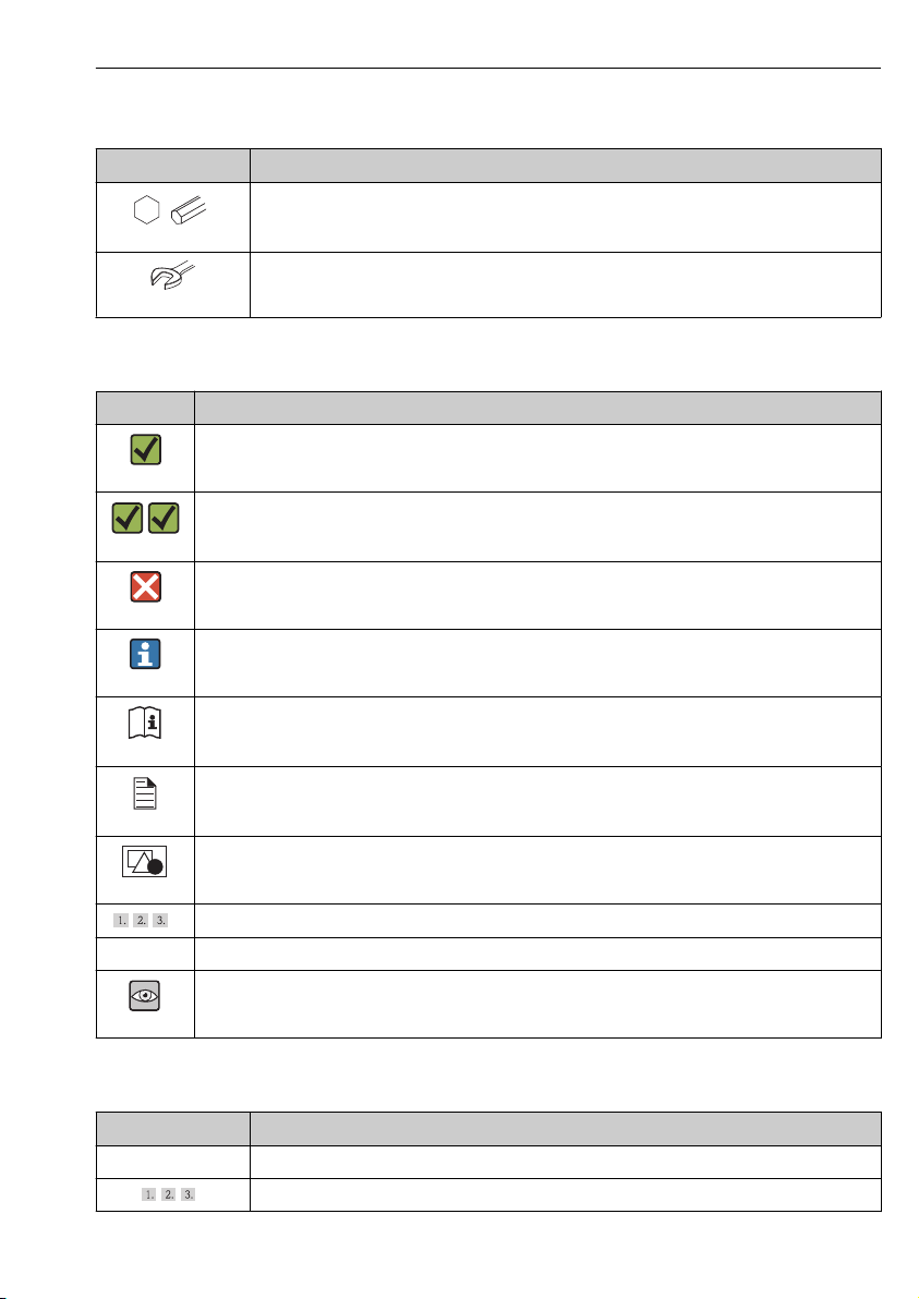
1.1.3 Tool symbols
Symbol Meaning
Allen key
A0011221
Open-ended wrench
A0011222
1.1.4 Symbols for certain types of information
Symbol Meaning
Allowed
Indicates procedures, processes or actions that are allowed.
A0011182
Preferred
Indicates procedures, processes or actions that are preferred.
A0011183
Forbidden
Indicates procedures, processes or actions that are forbidden.
A0011184
Tip
Indicates additional information.
A0011193
Reference to documentation
Refers to the corresponding device documentation.
A0011194
Reference to page
Refers to the corresponding page number.
A0011195
Reference to graphic
Refers to the corresponding graphic number and page number.
A0011196
Series of steps
Result of a sequence of actions
Visual inspection
A0015502
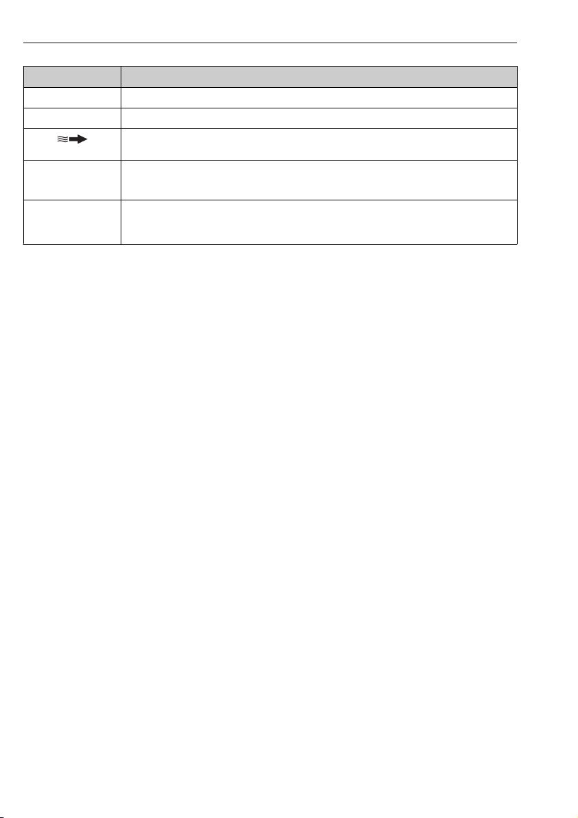
1.1.5 Symbols in graphics
Symbol Meaning
1, 2, 3,... Item numbers
Series of steps
Endress+Hauser 5
Page 6
Basic safety instructions CNGmass
-
.
Symbol Meaning
A, B, C, ... Views
A-A, B-B, C-C, ... Sections
Flow direction
A0013441
Hazardous area
Indicates a hazardous area.
A0011187
Safe area (non-hazardous area)
Indicates a non-hazardous area.
A0011188
2 Basic safety instructions
2.1 Requirements for the personnel
The personnel must fulfill the following requirements for its tasks:
Trained, qualified specialists must have a relevant qualification for this specific function
‣
and task
Are authorized by the plant owner/operator
‣
Are familiar with federal/national regulations
‣
Before beginning work, the specialist staff must have read and understood the instructions
‣
in the Operating Instructions and supplementary documentation as well as in the
certificates (depending on the application)
Following instructions and basic conditions
‣
2.2 Designated use
Application and media
The measuring device described in these Instructions is intended only for flow measurement
of liquids and gases.
Depending on the version ordered, the measuring device can also measure potentially
explosive, flammable, poisonous and oxidizing media.
Measuring devices for use in hazardous areas, in hygienic applications or in applications
where there is an increased risk due to process pressure, are labeled accordingly on the
nameplate.
To ensure that the measuring device remains in proper condition for the operation time:
Only use the measuring device in full compliance with the data on the nameplate and the
‣
general conditions listed in the Operating Instructions and supplementary documentation.
Based on the nameplate, check whether the ordered device is permitted for the intended
‣
use in the hazardous area (e.g. explosion protection, pressure vessel safety).
Use the measuring device only for media against which the process-wetted materials are
‣
adequately resistant.
6 Endress+Hauser
Page 7

CNGmass Basic safety instructions
If the measuring device is not operated at atmospheric temperature, compliance with the
‣
relevant basic conditions specified in the associated device documentation is absolutely
essential: "Device documentation" section → 11.
Incorrect use
Non-designated use can compromise safety. The manufacturer is not liable for damage caused
by improper or non-designated use.
WARNING
L
Danger of breakage of the measuring tube due to corrosive or abrasive fluids.
Housing breakage due to mechanical overload possible!
Verify the compatibility of the process fluid with the measuring tube material.
‣
Ensure the resistance of all fluid-wetted materials in the process.
‣
Observe the specified pressure and temperature range.
‣
Verification for borderline cases:
For special fluids and fluids for cleaning, Endress+Hauser is glad to provide assistance in
‣
verifying the corrosion resistance of fluid-wetted materials, but does not accept any
warranty or liability as minute changes in the temperature, concentration or level of
contamination in the process can alter the corrosion resistance properties.
Residual risks
The external surface temperature of the housing can increase by max. 20 K due to the power
consumption of the electronic components. Hot process fluids passing through the measuring
device will further increase the surface temperature of the housing. The surface of the sensor,
in particular, can reach temperatures which are close to the fluid temperature.
Possible burn hazard due to fluid temperatures!
For elevated fluid temperature, ensure protection against contact to prevent burns.
‣
2.3 Workplace safety
For work on and with the device:
Wear the required personal protective equipment according to federal/national
‣
regulations.
For welding work on the piping:
Do not ground the welding unit via the measuring device.
‣
If working on and with the device with wet hands:
It is recommended to wear gloves on account of the higher risk of electric shock.
‣
2.4 Operational safety
Risk of injury.
Operate the device in proper technical condition and fail-safe condition only.
‣
The operator is responsible for interference-free operation of the device.
‣
Endress+Hauser 7
Page 8

Basic safety instructions CNGmass
2.5 Product safety
This measuring device is designed in accordance with good engineering practice to meet stateof-the-art safety requirements, has been tested, and left the factory in a condition in which it
is safe to operate.
It meets general safety standards and legal requirements. It also complies with the EC
directives listed in the device-specific EC Declaration of Conformity. Endress+Hauser confirms
this by affixing the CE mark to the device.
2.6 IT security
We only provide a warranty if the device is installed and used as described in the Operating
Instructions. The device is equipped with security mechanisms to protect it against any
inadvertent changes to the device settings.
IT security measures in line with operators' security standards and designed to provide
additional protection for the device and device data transfer must be implemented by the
operators themselves.
Endress+Hauser can be contacted to provide support in performing this task.
8 Endress+Hauser
Page 9
CNGmass Product description
2
3
4
1
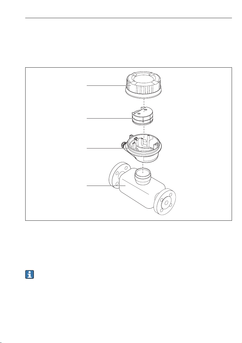
3 Product description
3.1 Product design
3.1.1 Device version with Modbus RS485 communication types
A0017609
1 Important components of a measuring device
1 Transmitter housing cover
2 Main electronics module
3 Transmitter housing
4 Sensor
In the case of the device version with Modbus RS485 intrinsically safe, the Safety Barrier
Promass 100 forms part of the scope of supply.
Endress+Hauser 9
Page 10
Incoming acceptance and product identification CNGmass
1
+
2
1
+
2
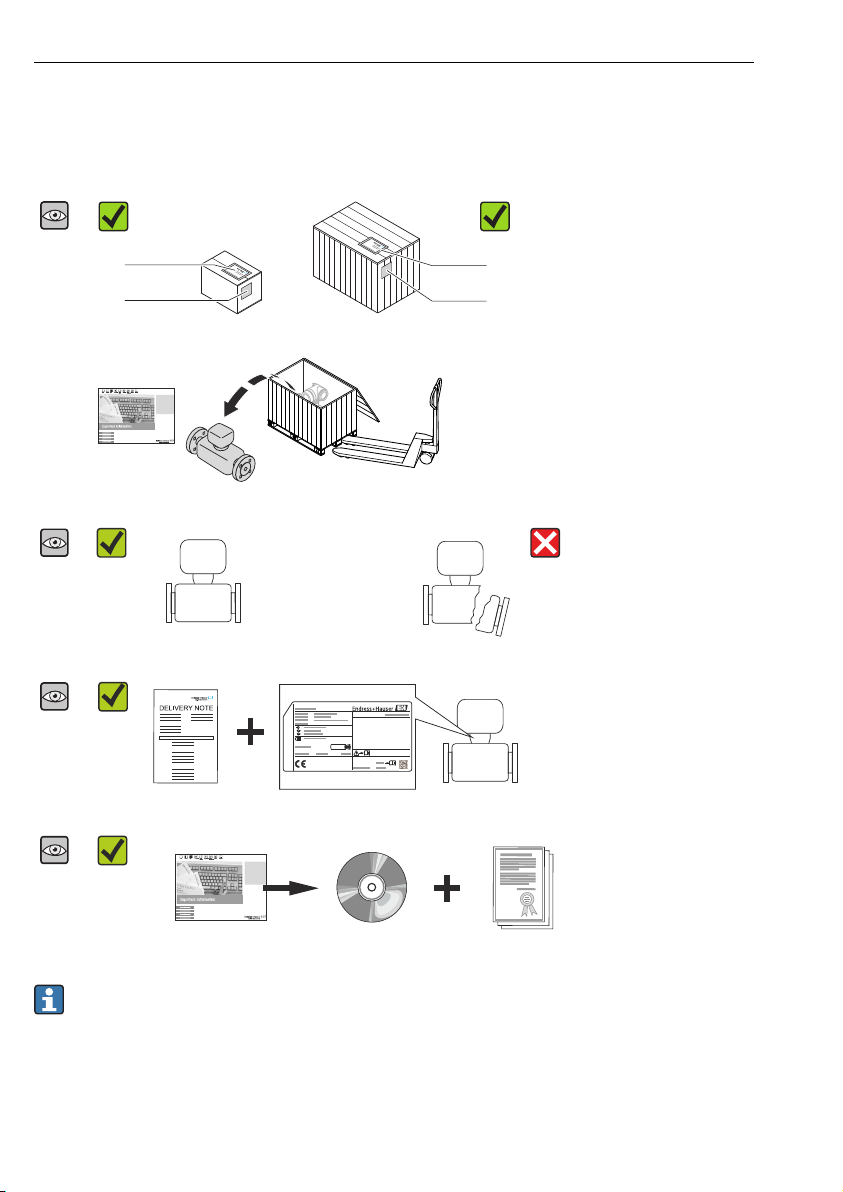
4 Incoming acceptance and product identification
4.1 Incoming acceptance
Are the order codes on the
A0015502
A0013843
A0013695
A0015502
delivery note (1) and the
product sticker (2) identical?
Are the goods undamaged?
A0013698
Do the nameplate data match
A0015502
A0013699
A0015502
A0013697
the ordering information on
the delivery note?
Is the CD-ROM with the
Technical Documentation
(depends on device version)
and documents present?
• If one of the conditions is not satisfied, contact your Endress+Hauser Sales Center.
• Depending on the device version, the CD-ROM might not be part of the delivery! In
such cases, the technical documentation is available via the Internet or via the Endress
+Hauser Operations App, see the "Device documentation" section → 11.
10 Endress+Hauser
Page 11

CNGmass Incoming acceptance and product identification
Order code:
Ext. ord. cd.:
Ser. no.:
1
2
3
4
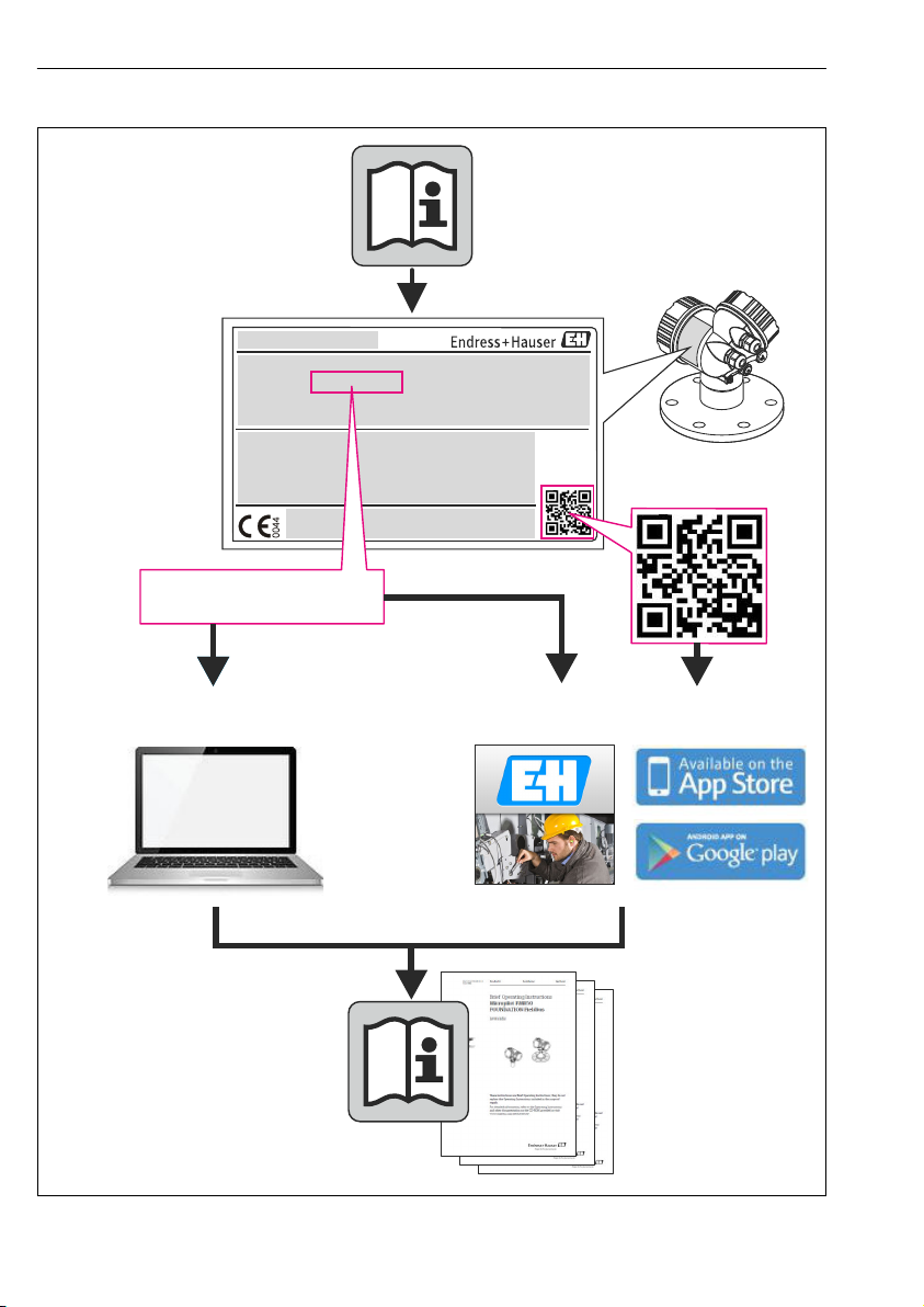
4.2 Product identification
The following options are available for identification of the measuring device:
• Nameplate specifications
• Order code with breakdown of the device features on the delivery note
• Enter serial numbers from nameplates in W@M Device Viewer
(www.endress.com/deviceviewer): All information about the measuring device is displayed.
• Enter the serial number from the nameplates into the Endress+Hauser Operations App or
scan the 2-D matrix code (QR code) on the nameplate with the Endress+Hauser Operations
App: all the information for the measuring device is displayed.
A0021952
2 Example of a nameplate
1 Order code
2 Serial number (Ser. no.)
3 Extended order code (Ext. ord. cd.)
4 2-D matrix code (QR code)
For detailed information on the breakdown of the specifications on the nameplate, see
the Operating Instructions for the device → 11.
4.2.1 Device documentation
All devices are supplied with Brief Operating Instructions. These Brief Operating
Instructions are not a substitute for the Operating Instructions pertaining to the device!
Detailed information about the device can be found in the Operating Instructions and the
other documentation:
• On the CD-ROM supplied (is not included in the delivery for all device versions).
• Available for all device versions via:
– Internet: www.endress.com/deviceviewer
– Smart phone/tablet: Endress+Hauser Operations App
Endress+Hauser 11
Page 12

Storage and transport CNGmass
The information required to retrieve the documentation can be found on the nameplate of the
device → 2, 11.
Technical documentation can also be downloaded from the Download Area of the
Endress+Hauser web site: www.endress.com → Download. However this technical
documentation applies to a particular instrument family and is not assigned to a specific
device.
W@M Device Viewer
1. Launch the W@M Device Viewer: www.endress.com/deviceviewer
2. Enter the serial number (Ser. no.) of the device: see nameplate → 2, 11.
All the associated documentation is displayed.
Endress+Hauser Operations App
The Endress+Hauser Operations App is available both for android smart phones (Google
Play store) and for iPhones and iPads (App Store).
Via the serial number:
1. Launch the Endress+Hauser Operations App.
2. Enter the serial number (Ser. no.) of the device: see nameplate → 2, 11.
All the associated documentation is displayed.
Via the 2-D matrix code (QR code):
1. Launch the Endress+Hauser Operations App.
2. Scan the 2-D matrix code (QR code) on the nameplate → 2, 11.
All the associated documentation is displayed.
5 Storage and transport
5.1 Storage conditions
Observe the following notes for storage:
• Store in original packaging.
• Do not remove protective covers or protective caps installed on process connections.
• Protect from direct sunlight.
• Storage temperature: –40 to +80 °C (–40 to +176 °F)
• Store in a dry and dust-free place.
• Do not store outdoors.
12 Endress+Hauser
Page 13

CNGmass Storage and transport
5.2 Transporting the product
WARNING
L
Center of gravity of the measuring device is higher than the suspension points of the
webbing slings.
Risk of injury if the measuring device slips.
Secure the measuring device from rotating or slipping.
‣
Observe the weight specified on the packaging (stick-on label).
‣
Observe the transport instructions on the stick-on label on the electronics compartment
‣
cover.
A0015606
Observe the following notes during transport:
• Transport the measuring device to the measuring point in the original packaging.
• Do not remove protective covers or protective caps installed on process connections. They
prevent mechanical damage to the sealing surfaces and fouling in the measuring tube.
A0015604
A0015605
Endress+Hauser 13
Page 14

Installation CNGmass
6 Installation
6.1 Installation conditions
No special measures such as supports are necessary. External forces are absorbed by the
construction of the device.
6.1.1 Mounting position
Inlet and outlet runs
No special precautions need to be taken for fittings which create turbulence, such as valves,
elbows or T-pieces, as long as no cavitation occurs .
A0015597 A0015598
For the dimensions and installation lengths of the device, see the "Technical Information"
document, "Mechanical construction" section
6.1.2 Requirements from environment and process
Ambient temperature range
Measuring device –40 to +60 °C (–40 to +140 °F)
Safety Barrier Promass 100 –40 to +60 °C (–40 to +140 °F)
If operating outdoors:
‣
Avoid direct sunlight, particularly in warm climatic regions.
Vibrations
The high oscillation frequency of the measuring tubes ensures that the correct operation of
the measuring system is not influenced by plant vibrations.
6.1.3 Special mounting instructions
Rupture disk
Make sure that the function and operation of the rupture disk is not impeded through the
installation of the device. The position of the rupture disk is indicated on a sticker applied over
it. If the rupture disk is triggered, the sticker is destroyed. The disk can therefore be visually
monitored. For additional information that is relevant to the process .
14 Endress+Hauser
Page 15

CNGmass Installation
A0022770
3 Rupture disk label
For detailed information about using a rupture disk, refer to the Operating Instructions
for the device on the CD-ROM provided
Zero point adjustment
All measuring devices are calibrated in accordance with state-of-the-art technology.
Calibration takes place under reference conditions . Therefore, a zero point adjustment in the
field is generally not required.
Experience shows that zero point adjustment is advisable only in special cases:
• To achieve maximum measuring accuracy even with low flow rates
• Under extreme process or operating conditions (e.g. very high process temperatures or very
high-viscosity fluids).
6.2 Mounting the measuring device
6.2.1 Required tools
For sensor
For flanges and other process connections: Corresponding mounting tools
6.2.2 Preparing the measuring device
1. Remove all remaining transport packaging.
2. Remove any protective covers or protective caps present from the sensor.
3. Remove stick-on label on the electronics compartment cover.
Endress+Hauser 15
Page 16

Installation CNGmass
6.2.3 Mounting the measuring device
WARNING
L
Danger due to improper process sealing!
Ensure that the inside diameters of the gaskets are greater than or equal to that of the
‣
process connections and piping.
Ensure that the gaskets are clean and undamaged.
‣
Install the gaskets correctly.
‣
1. Ensure that the direction of the arrow on the nameplate of the sensor matches the flow
direction of the fluid.
2. Install the measuring device or turn the transmitter housing so that the cable entries do
not point upwards.
A0013964
6.3 Post-installation check
Is the device undamaged (visual inspection)?
Does the measuring device conform to the measuring point specifications?
For example:
• Process temperature
• Process pressure (refer to the chapter on "Material load curves" of the "Technical Information"
document on the CD-ROM provided)
• Ambient temperature → 14
• Measuring range
Has the correct orientation for the sensor been selected ?
• According to sensor type
• According to medium temperature
• According to medium properties (outgassing, with entrained solids)
Does the arrow on the sensor nameplate match the direction of flow of the fluid through the piping ?
Are the measuring point identification and labeling correct (visual inspection)?
Is the device adequately protected from precipitation and direct sunlight?
Are the securing screw and securing clamp tightened securely?
16 Endress+Hauser
Page 17

CNGmass Electrical connection
7 Electrical connection
The measuring device does not have an internal circuit breaker. For this reason, assign
the measuring device a switch or power-circuit breaker so that the power supply line can
be easily disconnected from the mains.
7.1 Connection conditions
7.1.1 Required tools
• For cable entries: Use corresponding tools
• For securing clamp (on aluminum housing): Allen screw3 mm
• For securing screw (for stainless steel housing): open-ended wrench 8 mm
• Wire stripper
• When using stranded cables: crimping tool for ferrule
7.1.2 Requirements for connecting cable
The connecting cables provided by the customer must fulfill the following requirements.
Electrical safety
In accordance with applicable federal/national regulations.
Permitted temperature range
• –40 °C (–40 °F) to +80 °C (+176 °F)
• Minimum requirement: cable temperature range ≥ ambient temperature +20 K
Power supply cable
Standard installation cable is sufficient.
Signal cable
Modbus RS485
The EIA/TIA-485 standard specifies two types of cable (A and B) for the bus line which can be
used for every transmission rate. Cable type A is recommended.
Cable type A
Characteristic impedance 135 to 165 Ωat a measuring frequency of 3 to 20 MHz
Cable capacitance <30 pF/m
Wire cross-section
Cable type Twisted pairs
Loop resistance ≤110 Ω/km
Signal damping Max. 9 dB over the entire length of the cable cross-section
Shielding Copper braided shielding or braided shielding with foil shield. When grounding the
Endress+Hauser 17
>0.34 mm2 (22 AWG)
cable shield, observe the grounding concept of the plant.
Page 18

Electrical connection CNGmass
Connecting cable between Safety Barrier Promass 100 and measuring device
Cable type Shielded twisted-pair cable with 2x2 wires. When grounding the cable shield, observe
Maximum cable resistance 2.5 Ω, one side
Comply with the maximum cable resistance specifications to ensure the operational
‣
the grounding concept of the plant.
reliability of the measuring device.
Wire cross-section Maximum cable length
[mm2] [AWG] [m] [ft]
0.5 20 70 230
0.75 18 100 328
1.0 17 100 328
1.5 16 200 656
2.5 14 300 984
Cable diameter
• Cable glands supplied:
M20 × 1.5 with cable 6 to 12 mm (0.24 to 0.47 in)
• Spring terminals:
Wire cross-sections 0.5 to 2.5 mm2 (20 to 14 AWG)
• With Safety Barrier Promass 100:
Plug-in screw terminals for wire cross-sections 0.5 to 2.5 mm2 (20 to 14 AWG)
18 Endress+Hauser
Page 19

CNGmass Electrical connection
L
L
62
72AB
10
20
+
_
1
2
7.1.3 Terminal assignment
Transmitter
Modbus RS485 connection version, for use in intrinsically safe areas
Order code for "Output", option M (connection via Safety Barrier Promass 100)
Order code for
"Housing"
Options
A
Order code for "Housing":
Option A: compact, coated aluminum
Connection methods available
Output
Terminals Terminals • Option B: thread M20x1
Power
supply
• Option C: thread G ½"
• Option D: thread NPT ½"
Possible options for order code
"Electrical connection"
4 Modbus RS485 terminal assignment, connection version for use in intrinsically safe areas
(connection via Safety Barrier Promass 100)
1 Intrinsically safe power supply
2 Modbus RS485
A0017053
Order code for
"Output"
Option M Intrinsically safe supply voltage Modbus RS485 intrinsically safe
Order code for "Output":
Option M: Modbus RS485, for use in intrinsically safe areas (connection via Safety Barrier Promass 100)
Endress+Hauser 19
20 (L-) 10 (L+) 72 (B) 62 (A)
Page 20

Electrical connection CNGmass
A
Safe area
1
L+2L
27
26
A B
Power
supply
24V
DC
Modbus
RS485
10207262
L+L A B
Power
supply
Modbus
RS485
Hazardous area
Safety Barrier
Promass 100
Power
Communication
Lift panel for
bus termination
1
2
A
Safety Barrier Promass 100
A0016922
5 Safety Barrier Promass 100 with terminals
1 Non-hazardous area and Zone 2/Div. 2
2 Intrinsically safe area
7.1.4 Shielding and grounding
The shielding and grounding concept requires compliance with the following:
• Electromagnetic compatibility (EMC)
• Explosion protection
• Personal protection equipment
• National installation regulations and guidelines
• Observe cable specification → 17.
• Keep the stripped and twisted lengths of cable shield to the ground terminal as short as
possible.
• Seamless cable shielding.
Grounding of the cable shield
To comply with EMC requirements:
• Ensure the cable shield is grounded to the potential matching line at multiple points.
• Connect every local ground terminal to the potential matching line.
NOTICE
In systems without potential matching, the multiple grounding of the cable shield causes
mains frequency equalizing currents!
Damage to the bus cable shield.
Only ground the bus cable shield to either the local ground or the protective ground at one
‣
end.
20 Endress+Hauser
Page 21

CNGmass Electrical connection
1 2
A
7.1.5 Preparing the measuring device
1. Remove dummy plug if present.
2.
NOTICE
Insufficient sealing of the housing!
Operational reliability of the measuring device could be compromised.
Use suitable cable glands corresponding to the degree of protection.
‣
If measuring device is delivered without cable glands:
Provide suitable cable gland for corresponding connecting cable → 17.
3. If measuring device is delivered with cable glands:
Observe cable specification → 17.
7.2 Connecting the measuring device
NOTICE
Limitation of electrical safety due to incorrect connection!
For use in potentially explosive atmospheres, observe the information in the device-specific
‣
Ex documentation.
7.2.1 Connecting the transmitter
A0019824
6 Device versions and connection versions
A Housing version: compact, aluminum coated
1 Cable entry for signal transmission
2 Cable entry for supply voltage
Endress+Hauser 21
Page 22

Electrical connection CNGmass
10 (0.4)
mm (in)
1
3 mm
A0021923
7 Device versions with connection example
1 Cable
Connect the cable in accordance with the terminal assignment .
‣
7.2.2 Connecting the Safety Barrier Promass 100
In the case of the device version with Modbus RS485 intrinsically safe, the transmitter must
be connected to the Safety Barrier Promass 100.
22 Endress+Hauser
Page 23

CNGmass Electrical connection
21
A
B
A
B
3
L+
L-
A
B
L+
L-
L- L+
A
B
5 6 7
8
4
A0016804
8 Electrical connection between the transmitter and Safety Barrier Promass 100
1 Control system (e.g. PLC)
2 Observe cable specification
3 Safety Barrier Promass 100: terminal assignment → 20
4 Observe cable specification → 17
5 Non-hazardous area
6 Non-hazardous area and Zone 2/Div. 2
7 Intrinsically safe area
8 Transmitter: terminal assignment
7.3 Hardware settings
7.3.1 Enabling the terminating resistor
Modbus RS485
To avoid incorrect communication transmission caused by impedance mismatch, terminate
the Modbus RS485 cable correctly at the start and end of the bus segment.
Endress+Hauser 23
Page 24

Electrical connection CNGmass
26
27AB
220 W
ON
1 2
A
A
If the transmitter is used in the intrinsically safe area
A0017791
9 Terminating resistor can be enabled via DIP switch in the Safety Barrier Promass 100
7.4 Ensuring the degree of protection
The measuring device fulfills all the requirements for the IP66/67 degree of protection, Type
4X enclosure.
To guarantee IP66/67 degree of protection, Type 4X enclosure, carry out the following steps
after the electrical connection:
1. Check that the housing seals are clean and fitted correctly. Dry, clean or replace the
seals if necessary.
2. Tighten all housing screws and screw covers.
3. Firmly tighten the cable glands.
24 Endress+Hauser
Page 25

CNGmass Electrical connection
4. To ensure that moisture does not enter the cable entry, route the cable so that it loops
down before the cable entry ("water trap").
A0013960
5. Insert dummy plugs into unused cable entries.
7.5 Post-connection check
Are cables or the device undamaged (visual inspection)?
Do the cables comply with the requirements → 17?
Do the cables have adequate strain relief?
Are all the cable glands installed, firmly tightened and leak-tight? Cable run with "water trap" → 24 ?
• Does the supply voltage match the specifications on the transmitter nameplate ?
• For device version with Modbus RS485 intrinsically safe: does the supply voltage match the
specifications on the nameplate of the Safety Barrier Promass 100 ?
Is the terminal assignment correct?
• If supply voltage is present, is the power LED on the electronics module of the transmitter lit green
→ 9?
• For device version with Modbus RS485 intrinsically safe, if supply voltage is present, is the power LED
on the Safety Barrier Promass 100 lit → 9?
Depending on the device version, is the securing clamp or fixing screw firmly tightened?
Endress+Hauser 25
Page 26

Operation options CNGmass
!
Expert
Operating menu for experts
Language
Operation
Setup
Diagnostics
Operating menu for operators and maintenances
Operator
Maintenance
task-oriented
function-oriented
Expert
8 Operation options
8.1 Structure and function of the operating menu
8.1.1 Structure of the operating menu
10 Schematic structure of the operating menu
8.1.2 Operating philosophy
The individual parts of the operating menu are assigned to certain user roles. Each user role
corresponds to typical tasks within the device lifecycle.
For detailed information about the operating philosophy of the device, see the Operating
A0014058-EN
Instructions for the device → 11.
8.2 Access to the operating menu via the operating tool
For detailed information about access to the operating menu via operating tool, refer to
the Operating Instructions for the device → 11.
26 Endress+Hauser
Page 27

CNGmass Operation options
1
2
3
8.2.1 Via service interface (CDI)
This communication interface is present in the following device version:
Order code for "Output", option M: Modbus RS485
A0016925
1 Service interface (CDI) of the measuring device
2 Commubox FXA291
3 Computer with "FieldCare" operating tool with COM DTM "CDI Communication FXA291"
8.2.2 Establishing a connection For device version with Modbus RS485 communication type
Via service interface (CDI) and "FieldCare" operating tool
1. Start FieldCare and launch the project.
2. In the network: Add a device.
The Add device window opens.
3. Select the CDI Communication FXA291 option from the list and press OK to confirm.
4. Right-click CDI Communication FXA291 and select the Add device option in the
context menu that opens.
5. Select the desired device from the list and press OK to confirm.
6. Establish the online connection to the device.
For details, see Operating Instructions BA00027S and BA00059S
Endress+Hauser 27
Page 28

System integration CNGmass
9 System integration
For information on system integration, see the Operating Instructions for the device
→ 11.
10 Commissioning
10.1 Function check
Before commissioning the device, make sure that the post-installation and post-connection
checks have been performed.
• "Post-installation check" checklist → 16
• "Post-connection check" checklist → 25
10.2 Establishing a connection via FieldCare
• For FieldCare connection → 26
• For establishing a connection via FieldCare → 27
10.3 Configuring the measuring device
The Setup menu with its submenus is used for fast commissioning of the measuring device.
The submenus contain all the parameters required for configuration, such as parameters for
measurement or communication.
Submenu Meaning
System units Configuring the units for all measured values
Medium selection Defining the medium
Communication Configuration of the digital communication interface
Low flow cut off Configuring the low flow cut off
Partial filled pipe detection Configuring the monitoring of partial and empty pipe
detection
10.4 Defining the tag name
To enable fast identification of the measuring point within the system, you can enter a unique
designation using the Device tag parameter and thus change the factory setting.
Parameter overview with brief description
Parameter Description User entry Factory setting
Device tag Enter the name for the
measuring point.
28 Endress+Hauser
Max. 32 characters, such as
letters, numbers or special
characters (e.g. @, %, /).
CNGmass
Page 29

CNGmass Diagnostic information
OFFON
1 - Write protection
2 - Not used
3 - Not used
4 - Not used
10.5 Protecting settings from unauthorized access
10.5.1 Write protection via write protection switch
The write protection switch makes it possible to block write access to the entire operating
menu with the exception of the following parameters:
• External pressure
• External temperature
• Reference density
• All parameters for configuring the totalizer
The parameter values are now read only and cannot be edited any more:
• Via service interface (CDI)
• Via Modbus RS485
For device version with Modbus RS485 communication types
Setting the write protection switch on the electronics module to the ON position enables
‣
the hardware write protection.
If hardware write protection is enabled, the Hardware locked option is displayed in
the Locking status parameter.
11 Diagnostic information
Any faults detected by the measuring device are displayed on the home page of the operating
tool once the connection has been established and on the home page of the web browser once
the user has logged on.
Remedial measures are provided for each diagnostic event to ensure that problems can be
rectified quickly.
FieldCare: Remedial measures are displayed on the home page in a separate field below the
diagnostic event.
Endress+Hauser 29
A0022571
Page 30

Page 31

Page 32

www.addresses.endress.com
 Loading...