

Page 1
0
BA00182C/07/EN/21.19
71464663
2019-12-31
Products Solutions Services
Operating Instructions
Indumax CLS50D/CLS50
Digital sensor with Memosens protocol or analog
sensor
For inductive measurement of conductivity in
liquids
Page 2
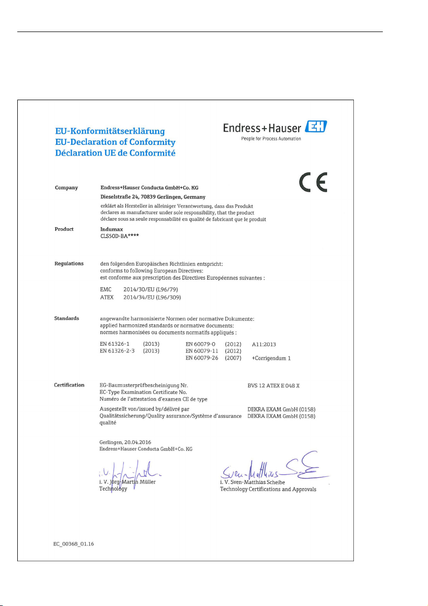
EU Declaration of Conformity Indumax CLS50D/CLS50
EU Declaration of Conformity
CLS50D-BA****
2 Endress+Hauser
Page 3
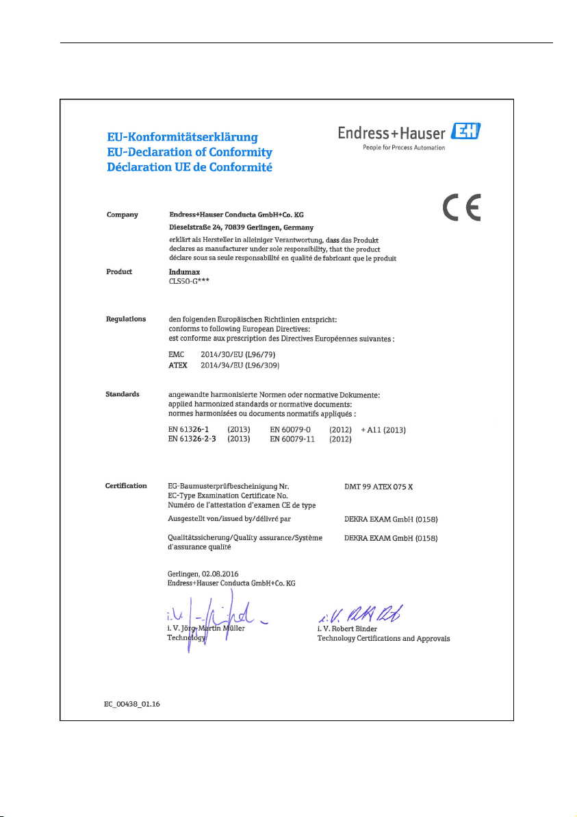
Indumax CLS50D/CLS50 EU Declaration of Conformity
CLS50-G***
Endress+Hauser 3
Page 4
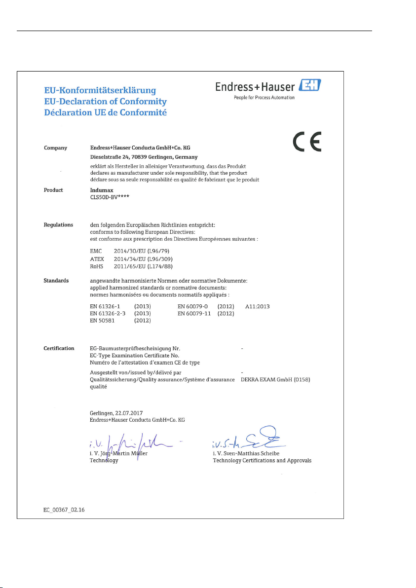
EU Declaration of Conformity Indumax CLS50D/CLS50
CLS50D-BV****
4 Endress+Hauser
Page 5
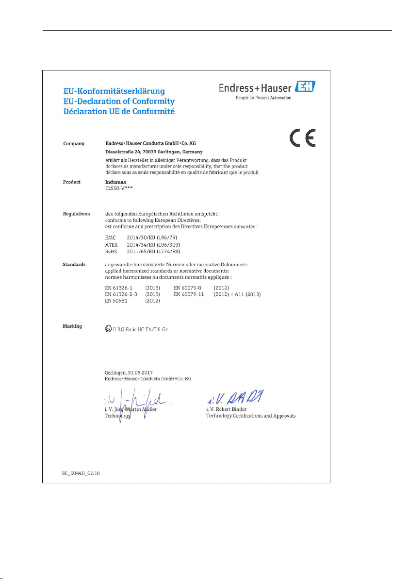
Indumax CLS50D/CLS50 EU Declaration of Conformity
CLS50-V***
Endress+Hauser 5
Page 6

Table of contents Indumax CLS50D/CLS50
Table of contents
1 About this document ........... 7
1.1 Warnings ........................... 7
1.2 Symbols used ........................ 7
1.3 Symbols on the device ................ 8
10.2 Performance characteristics .......... 36
10.3 Environment ....................... 36
10.4 Process ............................ 37
10.5 Mechanical construction ............. 39
2 Basic safety instructions ....... 9
2.1 Requirements for personnel ........... 9
2.2 Designated use ...................... 9
2.3 Workplace safety .................... 9
2.4 Operational safety .................. 10
2.5 Product safety ...................... 10
3 Incoming acceptance and
product identification ......... 14
3.1 Incoming acceptance ................ 14
3.2 Product identification ................ 14
3.3 Scope of delivery .................... 17
3.4 Certificates and approvals ............ 18
4 Installation .................... 19
4.1 Installation conditions ............... 19
4.2 Mounting the sensor ................ 21
4.3 Post-installation check ............... 24
5 Electrical connection .......... 24
5.1 Connection conditions ............... 25
5.2 Connecting the sensor ............... 29
5.3 Ensuring the degree of protection ..... 30
5.4 Post-connection check ............... 30
6 Commissioning ................ 31
Index ................................. 42
7 Maintenance .................. 31
8 Repair .......................... 32
8.1 Spare parts ........................ 32
8.2 Return ............................ 33
8.3 Disposal ........................... 33
9 Accessories .................... 33
9.1 Measuring cable .................... 34
9.2 Assemblies ........................ 34
9.3 Calibration solutions ................ 35
10 Technical data ................. 35
10.1 Input .............................. 35
6 Endress+Hauser
Page 7
Indumax CLS50D/CLS50 About this document
1 About this document
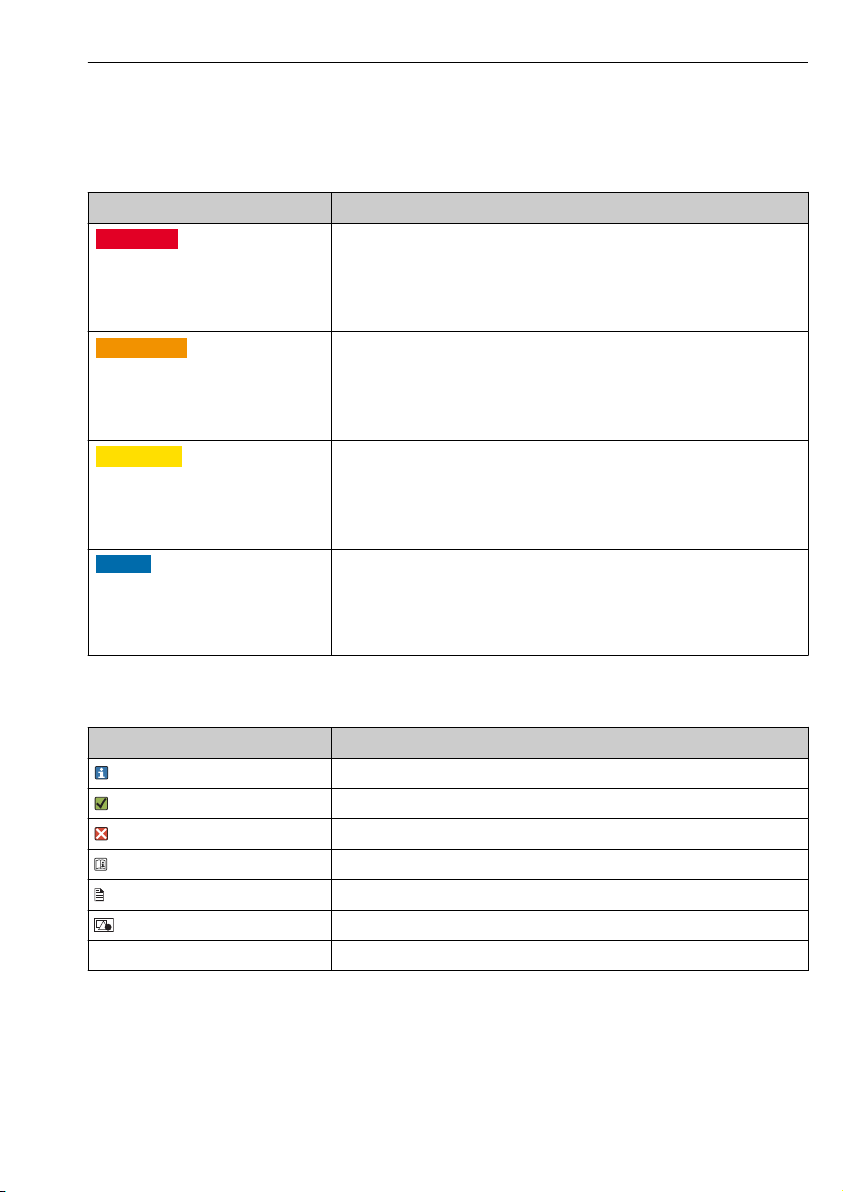
1.1 Warnings
Structure of information Meaning
DANGER
L
Causes (/consequences)
If necessary, Consequences of noncompliance (if applicable)
Corrective action
‣
WARNING
L
Causes (/consequences)
If necessary, Consequences of noncompliance (if applicable)
Corrective action
‣
CAUTION
L
Causes (/consequences)
If necessary, Consequences of noncompliance (if applicable)
Corrective action
‣
NOTICE
Cause/situation
If necessary, Consequences of noncompliance (if applicable)
Action/note
‣
This symbol alerts you to a dangerous situation.
Failure to avoid the dangerous situation will result in a fatal or serious injury.
This symbol alerts you to a dangerous situation.
Failure to avoid the dangerous situation can result in a fatal or serious injury.
This symbol alerts you to a dangerous situation.
Failure to avoid this situation can result in minor or more serious injuries.
This symbol alerts you to situations which may result in damage to property.
1.2 Symbols used
Symbol Meaning
Additional information, tips
Permitted or recommended
Not permitted or not recommended
Reference to device documentation
Reference to page
Reference to graphic
Result of a step
Endress+Hauser 7
Page 8
About this document Indumax CLS50D/CLS50
1.3 Symbols on the device
Symbol Meaning
Reference to device documentation
8 Endress+Hauser
Page 9

Indumax CLS50D/CLS50 Basic safety instructions
2 Basic safety instructions
2.1 Requirements for personnel
• Installation, commissioning, operation and maintenance of the measuring system may be
carried out only by specially trained technical personnel.
• The technical personnel must be authorized by the plant operator to carry out the specified
activities.
• The electrical connection may be performed only by an electrical technician.
• The technical personnel must have read and understood these Operating Instructions and
must follow the instructions contained therein.
• Faults at the measuring point may only be rectified by authorized and specially trained
personnel.
Repairs not described in the Operating Instructions provided must be carried out only
directly at the manufacturer's site or by the service organization.
2.2 Designated use
Indumax CLS50D or CLS50 sensor is particularly suitable for use in the chemical and process
technology sectors. The six-decade measuring range and the excellent chemical resistance
properties of the materials in contact with the medium (PFA or PEEK) make it possible to use
this sensor in a wide range of applications, such as:
• Concentration measurement of acids and bases
• Quality monitoring of chemical products in tanks and pipes
• Phase separation of product/product mixtures
The digital sensor CLS50D is used in conjunction with the Liquiline CM44x/R or Liquiline M
CM42, while the analog sensor CLS50 is used with the Liquiline M CM42 or
Liquisys CLM223/253.
Use of the device for any purpose other than that described, poses a threat to the safety of
people and of the entire measuring system and is therefore not permitted.
The manufacturer is not liable for damage caused by improper or non-designated use.
2.3 Workplace safety
As the user, you are responsible for complying with the following safety conditions:
• Installation guidelines
• Local standards and regulations
• Regulations for explosion protection
Electromagnetic compatibility
• The product has been tested for electromagnetic compatibility in accordance with the
applicable international standards for industrial applications.
• The electromagnetic compatibility indicated applies only to a product that has been
connected in accordance with these Operating Instructions.
Endress+Hauser 9
Page 10

Basic safety instructions Indumax CLS50D/CLS50
2.4 Operational safety
Before commissioning the entire measuring point:
1. Verify that all connections are correct.
2. Ensure that electrical cables and hose connections are undamaged.
3. Do not operate damaged products, and protect them against unintentional operation.
4. Label damaged products as defective.
During operation:
If faults cannot be rectified:
‣
products must be taken out of service and protected against unintentional operation.
2.5 Product safety
2.5.1 State-of-the-art technology
The product is designed to meet state-of-the-art safety requirements, has been tested, and
left the factory in a condition in which it is safe to operate. The relevant regulations and
international standards have been observed.
2.5.2 Electrical equipment in hazardous areas
Sensors with ATEX approval (CLS50-G*** and CLS50D-BA**** for Zone 0, CLS50-V*** and
CLS50D-BV**** for Zone 2) have been developed and manufactured in compliance with
applicable European standards and guidelines and are suitable for use in hazardous areas. The
Declaration of Conformity confirms compliance with the harmonized European standards for
using the sensors in hazardous areas.
CLS50D-BA****, CLS50D-IA****, CLS50D-GB****, CLS50D-NA****, CLS50D-H****,
CLS50-G*** and CLS50-K***
• The sensors may be operated in an environment specified as Ex Zone 0 (1G).
• The sensors may only be used in liquid media with a conductivity >10 nS/cm.
• If the connecting cable runs through Ex Zone 0 (1G), it must be protected against
electrostatic charge.
CLS50D-BA****, CLS50D-IA****, CLS50D-NA**** and CLS50D-GB****
• The sensor is a digital sensor with the Memosens protocol and its connection values are
those specified below.
• The sensor may also be connected to the intrinsically safe Memosens connection of the
FSDG1 module of the Liquiline transmitter, types CM42-LE, CM42-LF, CM42-LI, EC typeexamination certificate EX5 05 03 30266 012 (ATEX or IECEx) or CM42-LK (EAC Ex).
• The maximum permitted length of the measuring cable is 100 m (330 ft) here.
Connection values of the CLS50D-BA****, CLS50D-IA**** and CLS50D-GB**** sensor
U
i
I
i
P
i
10 Endress+Hauser
5.1 V
130 mA
166 mW
Page 11
Indumax CLS50D/CLS50 Basic safety instructions
C
i
L
i
18 µF
72 µH
Temperature classes of CLS50D-BA****, CLS50D-IA**** and CLS50D-GB****
Temperature class Sensor Ambient temperature range TaMedium temperature range T
T4 CLS50D-BA/IA/
GB*D**
CLS50D-BA/IA/
GB*C**
CLS50D-BA/IA/
GB*B**
T6 CLS50D-BA/IA/
GB*D**
CLS50D-BA/IA/
GB*C**
CLS50D-BA/IA/
GB*B**
-20 to +60 ˚C
-20 to +60 ˚C
-20 to +60 ˚C
-20 to +60 ˚C
-20 to +60 ˚C
-20 to +60 ˚C
-20 to +110 ˚C
-20 to +120 ˚C
-20 to +120 ˚C
-20 to +70 ˚C
-20 to +70 ˚C
-20 to +70 ˚C
CLS50-G***
• The sensor may only be connected to the following transmitters:
• Liquiline types CM42-IG, CM42-IE, CM42-IF, EC type-examination certificate TÜV 13
ATEX 7459 X
• Mycom type CLM153-Z with transmitter module type FCL1, EC type-examination
certificate DMT 99 ATEX E 076
• Mycom type CLM153-G, EC type-examination certificate DMT 01 ATEX E 174
• The maximum permitted length of the measuring cable is 55 m (180 ft) here.
med
Temperature classes of CLS50-G***
Temperature class Sensor Ambient temperature range TaMedium temperature range T
T4 CLS50-G*** -20 to +125 ˚C -20 to +125 ˚C
T6 CLS50-G*** -20 to +75 ˚C -20 to +75 ˚C
med
CLS50D-BV**** and CLS50-V***
• The sensor may be operated in an environment specified as Ex Zone 2 (3G).
• The sensor may only be connected to the following transmitter:
Liquiline type CM42-LV (CLS50D) or CM42-IV (CLS50), EU Declaration of Conformity
EC_00143_01.16
• Only CLS50-V***: The maximum permitted length of the measuring cable is 55 m (180 ft)
here.
Endress+Hauser 11
Page 12
Basic safety instructions Indumax CLS50D/CLS50
Temperature classes of CLS50D-BV****
Temperature class Sensor Ambient temperature range TaMedium temperature range T
T4 CLS50D-BV*D**
CLS50D-BV*C**
CLS50D-BV*B**
T6 CLS50D-BV**** -20 to +60 ˚C -20 to +70 ˚C
-20 to +60 ˚C
-20 to +60 ˚C
-20 to +60 ˚C
-20 to +110 ˚C
-20 to +120 ˚C
-20 to +120 ˚C
med
Temperature classes of CLS50-V***
Temperature class Sensor Ambient temperature range TaMedium temperature range T
T4 CLS50-V*** -20 to +125 ˚C -20 to +125 ˚C
T6 CLS50-V*** -20 to +75 ˚C -20 to +75 ˚C
med
CLS50-K***
• The sensor may only be connected to the following transmitter:
Liquiline type CM42-IK
• The maximum permitted length of the measuring cable is 55 m (180 ft) here.
Temperature classes of CLS50-K***
Temperature class Sensor Ambient temperature range T
T4 CLS50-K*** -20 to +125 ˚C -20 to +125 ˚C
T6 CLS50-K*** -20 to +75 ˚C -20 to +75 ˚C
Medium temperature range T
a
med
Sensors with FM and CSA approval (CLS50D-FB****, CLS50D-C2****, CLS50-O***,
CLS50-S***)
Observe the documentation and the control drawings of the transmitter.
Sensors with NEPSI approval (CLS50D-NA**** and CLS50-H*** for Zone 0, CLS50-V***
for Zone 2)
Pay attention to the information on the NEPSI certificates. You can download these
certificates from the product page: www.endress.com/cls50d or www.endress.com/cls50.
Temperature classes of CLS50D-NA****
Temperature class Sensor Ambient temperature range TaMedium temperature range T
T4 CLS50D-NA*D**
CLS50D-NA*C**
CLS50D-NA*B**
T6 CLS50D-NA*D**
CLS50D-NA*C**
CLS50D-NA*B**
12 Endress+Hauser
-20 to +60 ˚C
-20 to +60 ˚C
-20 to +60 ˚C
-20 to +60 ˚C
-20 to +60 ˚C
-20 to +60 ˚C
-20 to +110 ˚C
-20 to +120 ˚C
-20 to +120 ˚C
-20 to +70 ˚C
-20 to +70 ˚C
-20 to +70 ˚C
med
Page 13
Indumax CLS50D/CLS50 Basic safety instructions
Temperature classes of CLS50-H***
Temperature class Sensor Ambient temperature range TaMedium temperature range T
T4 CLS50-H*** -20 to +125 ˚C -20 to +125 ˚C
T6 CLS50-H*** -20 to +75 ˚C -20 to +75 ˚C
med
Sensors with TIIS approval (CLS50D-TA****, CLS50-T***)
Sensors with TIIS approval may only be used in a Zone 1 (2G) environment.
The following also applies for all the sensors listed
• Compliance with the specified ambient and medium temperature ranges is a prerequisite
for safe use.
• The sensor must be connected and operated in accordance with the Operating Instructions
of the sensor and of the transmitter to be connected. All sensor operating data must be
observed.
• Avoid electrostatic charge. Metal process connections must be electrostatically connected (R
≤ 1 MΩ).
• Non-metal process connections must be protected against electrostatic charge.
• In order to avoid electrostatic charge clean the sensor with a damp cloth only.
• Full compliance with regulations for electrical systems in hazardous locations
(EN60079-14) is mandatory when using the devices and sensors.
• Ensure correct installation to maintain the housing protection type. (Use original seal. Fit
cable entry properly. Tighten nut).
• The degree of protection only applies when the flange is mounted.
CLS50 only
In the CLS50 sensor, the internal sensor circuits are connected with the shielded wire of
the supply cable. When installing the CM42 or CLM153 transmitter, the shielding of the
sensor cable must be connected to functional ground as prescribed. As a result, the
intrinsically safe sensor circuits of CLS50 are also connected to ground. Therefore, the
power supply of the transmitter must be galvanically isolated and connected to ground.
The CM42 and CLM153 transmitters already have secure internal galvanic isolation and
therefore safely separate the sensor circuit from the other circuits.
Endress+Hauser 13
Page 14
Incoming acceptance and product identification Indumax CLS50D/CLS50
3 Incoming acceptance and product identification
3.1 Incoming acceptance
1. Verify that the packaging is undamaged.
Notify the supplier of any damage to the packaging.
Keep the damaged packaging until the issue has been resolved.
2. Verify that the contents are undamaged.
Notify the supplier of any damage to the delivery contents.
Keep the damaged goods until the issue has been resolved.
3. Check that the delivery is complete and nothing is missing.
Compare the shipping documents with your order.
4. Pack the product for storage and transportation in such a way that it is protected
against impact and moisture.
The original packaging offers the best protection.
Make sure to comply with the permitted ambient conditions.
If you have any questions, please contact your supplier or your local Sales Center.
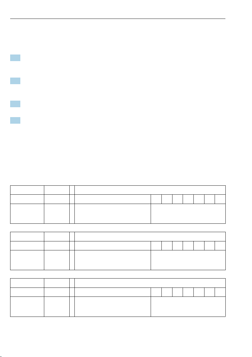
3.2 Product identification
3.2.1 Type code for versions with explosion protection
Name Type Version
Indumax - BA x x x x + x x
For use in hazardous areas, ATEX II 1G
Ex ia IIC T4/T6 Ga
Name Type Version
Indumax CLS50D - IA x x x x + x x
For use in hazardous areas, IECEx Ex ia
IIC T4/T6 Ga
Name Type Version
Indumax CLS50D - BV x x x x + x x
For use in hazardous areas, ATEX II 3G
Ex ic IIC T4/T6 Gc
14 Endress+Hauser
Process connections, materials, cable
connection, calibration, service
No Ex relevance
Process connections, materials, cable
connection, calibration, service
No Ex relevance
Process connections, materials, cable
connection, calibration, service
No Ex relevance
Page 15

Indumax CLS50D/CLS50 Incoming acceptance and product identification
Name Type Version
Indumax CLS50D - NA x x x x + x x
For use in hazardous areas, NEPSI Ex ia
IIC T4/T6 Ga
Name Type Version
Indumax CLS50D - C2 x x x x + x x
For use in hazardous areas, CSA IS NI
Cl.I Div.1&2,Gr. A-D
Name Type Version
Indumax CLS50D - FB x x x x + x x
For use in hazardous areas, FM IS NI
C1.I Div.1&2, Gr. A-D
Name Type Version
Indumax CLS50D - GB x B/C/Dx x + x x
Process connections, materials, cable
connection, calibration, service
No Ex relevance
Process connections, materials, cable
connection, calibration, service
No Ex relevance
Process connections, materials, cable
connection, calibration, service
No Ex relevance
For use in hazardous areas, EAC Ex, 0Ex
ia IIC T6/T4 Ga X
Name Type Version
Indumax CLS50D - TA x x x x + x x
For use in hazardous areas, TIIS Ex ib IIC
T4 Gb
Name Type Version
Indumax CLS50 - G x x x
For use in hazardous areas, ATEX II 1G
Ex ia IIC T4/T6 Ga
Endress+Hauser 15
Process connections, materials, cable
connection, calibration, service
No Ex relevance
Process connections, materials, cable
connection, calibration, service
No Ex relevance
Process connections, materials, cable
connection, calibration, service
No Ex relevance
Page 16

Incoming acceptance and product identification Indumax CLS50D/CLS50
Name Type Version
Indumax CLS50 - V x x x
For use in hazardous areas, ATEX II 3G
Ex ic IIC T4/T6 Gc / NEPSI Ex ic IIC
T4/T6 Gc
Name Type Version
Indumax CLS50 - H x x x
For use in hazardous areas, NEPSI Ex ia
IIC T4/T6 Ga
Name Type Version
Indumax CLS50 - O x x x
For use in hazardous areas, FM IS NI Cl.I
Div.1&2,Gr. A-D
Name Type Version
Indumax CLS50 - S x x x
For use in hazardous areas, CSA IS NI
Cl.I Div.1&2,Gr. A-D
Process connections, materials, cable
connection, calibration, service
No Ex relevance
Process connections, materials, cable
connection, calibration, service
No Ex relevance
Process connections, materials, cable
connection, calibration, service
No Ex relevance
Process connections, materials, cable
connection, calibration, service
No Ex relevance
Name Type Version
Indumax CLS50 - T x x x
For use in hazardous areas, TIIS Ex ib IIC
T4 Gb
Name Type Version
Indumax CLS50 - K x x 1/2
For use in hazardous areas, EAC Ex, 0Ex
ia IIC T6/T4 Ga X
16 Endress+Hauser
Process connections, materials, cable
connection, calibration, service
No Ex relevance
/3/
4
Process connections, materials, cable
connection, calibration, service
No Ex relevance
Page 17

Indumax CLS50D/CLS50 Incoming acceptance and product identification
3.2.2 Nameplate
The nameplate provides you with the following information on your device:
• Manufacturer identification
• Order code
• Serial number
• Ambient and process conditions
• Safety information and warnings
• Cell constant (nominal value)
• Degree of protection
• Ex labeling on hazardous area versions
Compare the information on the nameplate with the order.
‣
3.2.3 Product identification
Product page
www.endress.com/cls50d
www.endress.com/cls50
Interpreting the order code
The order code and serial number of your product can be found in the following locations:
• On the nameplate
• In the delivery papers
Obtaining information on the product
1. Go to www.endress.com.
2. Call up the site search (magnifying glass).
3. Enter a valid serial number.
4. Search.
The product structure is displayed in a popup window.
5. Click on the product image in the popup window.
A new window (Device Viewer) opens. All of the information relating to your
device is displayed in this window as well as the product documentation.
Manufacturer's address
Endress+Hauser Conducta GmbH+Co. KG
Dieselstraße 24
D-70839 Gerlingen
3.3 Scope of delivery
The scope of delivery includes:
• Sensor in the version ordered
• Operating Instructions
Endress+Hauser 17
Page 18

Incoming acceptance and product identification Indumax CLS50D/CLS50
If you have any queries:
‣
Please contact your supplier or local sales center.
3.4 Certificates and approvals
3.4.1
mark
Declaration of Conformity
The product meets the requirements of the harmonized European standards. As such, it
complies with the legal specifications of the EU directives. The manufacturer confirms
successful testing of the product by affixing to it the mark.
3.4.2 Ex approvals CLS50D-BA**** and CLS50-G***
ATEX II 1G Ex ia IIC T4/T6 Ga
CLS50D-BV****
ATEX II 3G Ex ic IIC T4/T6 Gc
CLS50D-IA****
IECEx Ex ia IIC T4/T6 Ga
CLS50-V***
ATEX II 3G Ex ic IIC T4/T6 Gc + NEPSI Ex ic IIC T4/T6 Gc
CLS50D-NA**** and CLS50-H***
NEPSI Ex ia IIC T4/T6 Ga
CLS50D-FB**** and CLS50-O***
FM IS NI Cl.I Div.1&2,G. A-D
CLS50D-C2**** and CLS50-S***
CSA IS NI Cl.I Div.1&2,Gr. A-D
CLS50D-TA**** and CLS50-T***
TIIS Ex ib IIC T4 Gb
CLS50D-GB**** and CLS50-K***
• EAC Ex, 0Ex ia IIC T6/T4 Ga X
• Zone 0
• Certificate number: TC RU C-DE.AA87.B.00088 and TC RU C-DE.ГБ05.B.00172 (only
CLS50-K***)
• The product has been certified in accordance with Directive TR CU 012/2011 which applies
in the European Economic Area (EEA). The EAC conformity mark has been affixed to the
product.
3.4.3 Certification body (only CLS50D-GB and CLS50-K)
OOO "НАНИО ЦСВЭ"
Russian Federation
18 Endress+Hauser
Page 19

Indumax CLS50D/CLS50 Installation
1
2
a
max. 100
(3.94)
3.4.4 Marine approvals
A selection of sensors have type approval for marine applications, issued by the following
classification societies: ABS (American Bureau of Shipping), BV (Bureau Veritas), DNV-GL
(Det Norske Veritas-Germanische Lloyd) and LR (Lloyd’s Register). Details of the order codes
of the approved sensors, and the installation and ambient conditions, are provided in the
relevant certificates for marine applications on the product page on the Internet.
4 Installation
4.1 Installation conditions
4.1.1 Installation position
When installing, align the sensor in such a way that the medium flows through the flow
‣
opening of the sensor in the direction of medium flow.
The sensor head must be completely immersed in the medium.
1 Sensor orientation, dimensions in mm (in)
1 Direction of medium flow
2 Minimum water level in the pipe
a Distance from pipe wall
4.1.2 Installation factor
In confined installation conditions, the conductivity measurement is affected by the pipe walls.
The installation factor compensates for this effect. The transmitter corrects the cell constant
Endress+Hauser 19
A0036463
Page 20

Installation Indumax CLS50D/CLS50
1
2
a [inch]
0
5
10 15
20
2525
a [mm]
0 80.
1 00.
1 20.
1 40.
f
0.20
0.39
0.59
0.79
0.98
by multiplying by the installation factor. The value of the installation factor depends on the
diameter and the conductivity of the pipe nozzle as well as the sensor's distance to the wall.
The installation factor f can be disregarded (f = 1.00) if the distance to the wall is sufficient (a
> 15 mm (0.59"), from DN 80). If the distance to the wall is smaller, the installation factor
increases for electrically insulating pipes (f > 1) and decreases for electrically conductive pipes
(f < 1). It can be measured using calibration solutions, or a close approximation determined
from the following diagram.
2 Relationship between installation factor f and wall distance
1 Electrically conductive pipe wall
2 Electrically insulating pipe wall
4.1.3 Air set
CLS50D
The digital sensor has already been adjusted at the factory. Onsite compensation is not
required.
CLS50
To compensate residual coupling in the cable and between the two sensor coils, zero
adjustment in air ("air set") must be performed before installing the sensor. Follow the
instructions provided in the Operating Instructions of the transmitter used.
20 Endress+Hauser
A0034874
Page 21

Indumax CLS50D/CLS50 Installation
1 2
3
5
4
4.2 Mounting the sensor
4.2.1 Installation with flange
The sensor is suitable for installation in T-pieces ≥ DN 80, with the outgoing diameter reduced
to ≥ DN 50.
WARNING
L
Leakage
Risk of injury if medium escapes!
Tighten sensor nut using a torque of 20 Nm.
‣
To avoid leakages, regularly check the tightness of the nut.
‣
Flange, not in contact with medium
A0024949
3 Fixed flange, not in contact with medium (for order option: "Process connection" = 5, 6, 7)
1 Flange (stainless steel)
2 Nut
3 Sealing disk (GYLON)
4 O-ring
5 Sensor
Endress+Hauser 21
Page 22

Installation Indumax CLS50D/CLS50
1 2
4
3
Flange, in contact with medium
A0024953
4 Fixed flange, in contact with medium (for order option: "Process connection" = 3, 4)
1 Flange (stainless steel)
2 Nut
3 O-ring
4 Sensor
22 Endress+Hauser
Page 23

Indumax CLS50D/CLS50 Installation
1 2
3
5
4
Lap joint flange, not in contact with medium
A0024954
5 Lap joint flange, not in contact with medium (for order option: "Process connection" = A, B, C)
1 Lap joint flange (PP-GF)
2 Nut (stainless steel)
3 Flange (PVDF)
4 O-ring
5 Sensor
Endress+Hauser 23
Page 24

Electrical connection Indumax CLS50D/CLS50
1 2
3
4
4.2.2 Installation in assembly
A0024960
6 Installation of sensor with assembly
1 CLA111 with suspension bracket
2 CLA111 with flange connection
3 CLA140 with flange connection
4 CYA112
4.3 Post-installation check
Put the sensor into operation only if you can answer yes to the following questions:
1. Are the sensor and cable undamaged?
2. Is the orientation correct (arrow on threaded sleeve=flow direction=installation
direction)?
3. Has the sensor been installed in the process connection, and does not suspend freely
from the cable?
5 Electrical connection
WARNING
L
Device is live!
Incorrect connection may result in injury or death!
The electrical connection may be performed only by an electrical technician.
‣
The electrical technician must have read and understood these Operating Instructions and
‣
must follow the instructions contained therein.
Prior to commencing connection work, ensure that no voltage is present on any cable.
‣
24 Endress+Hauser
Page 25

Indumax CLS50D/CLS50 Electrical connection
II 2G
II 1G
II 3G
Ex ia
Zone 1
Zone 0
Zone 2
CLS50-G
CLS50D-BA
CLS50-G
5.1 Connection conditions
5.1.1 Connection diagram: sensors for Zone 0 (ATEX/EAC Ex)
A0013258
Endress+Hauser 25
Page 26

Electrical connection Indumax CLS50D/CLS50
II 2G
II 1G
Ex ia
Zone 1
Zone 0
CLS50D-IA
5.1.2 Connection diagram: sensors for Zone 0 (IECEx)
A0025482
26 Endress+Hauser
Page 27

Indumax CLS50D/CLS50 Electrical connection
II 2G
II 1G
Ex ia
Zone 1
Zone 0
CLS50-H
CLS50D-NA
5.1.3 Connection diagram: sensors for Zone 0 (NEPSI)
A0025481
Endress+Hauser 27
Page 28

Electrical connection Indumax CLS50D/CLS50
Ex ic
CLS50-V
4...20 mA
II 3G
Zone 2
CLS50D-BV
5.1.4 Connection diagram: sensors for Zone 2 (ATEX/NEPSI)
A0010316
5.1.5 Sensors with FM or CSA approval
The instructions in the Control Drawing apply for sensors with FM or CSA approval. You can
find the Control Drawing in the Operating Instructions of the transmitter used.
28 Endress+Hauser
Page 29

Indumax CLS50D/CLS50 Electrical connection
BN
YE
Sensor cable
588
587
187
188
197
Device
198
387
388
Sensor
U
+
WH
GN
U
–
Com A
Com B
GN
WH
YE
Cable
217
218
215
216
112
CM42
111
113
J
Sensor
RD
BU
RD
BU
RD
WH
5.2 Connecting the sensor
5.2.1 Direct connection, e.g. to CM42
7 CLS50D to CM42
A0001078
8 CLS50 to CM42
Endress+Hauser 29
A0001082
Page 30

Electrical connection Indumax CLS50D/CLS50
GY
GY
GN
WH
BN
YE
PK
Shield
-
Com A
-
+
Com B
+
Memosens
U
U
Additional
sensor supply
WH
RD
Pt 100
YE
GN
RD
WH
BU
BN n.c.
RD
BU
5.2.2 Cable extension
The sensor is supplied with a fixed cable. The cable between the sensor and transmitter can be
extended using the CYK11 (CLS50D) or CLK6 (CLS50) measuring cable (does not apply for use
in a hazardous environment).
9 CYK11 for extension of CLS50D
Total cable length (max.): 100 m (330 ft)
A0017984
10 CLK6 for extension of CLS50
Total cable length (max.): 55 m (180 ft)
A0024937
CLS50 only:
The residual coupling of the sensor increases when the fixed cable is extended.
5.3 Ensuring the degree of protection
Only the mechanical and electrical connections which are described in these instructions and
which are necessary for the required, designated use, may be carried out on the device
delivered.
Exercise care when carrying out the work.
‣
Otherwise, the individual types of protection (Ingress Protection (IP), electrical safety, EMC
interference immunity) agreed for this product can no longer be guaranteed due, for example
to covers being left off or cable (ends) that are loose or insufficiently secured.
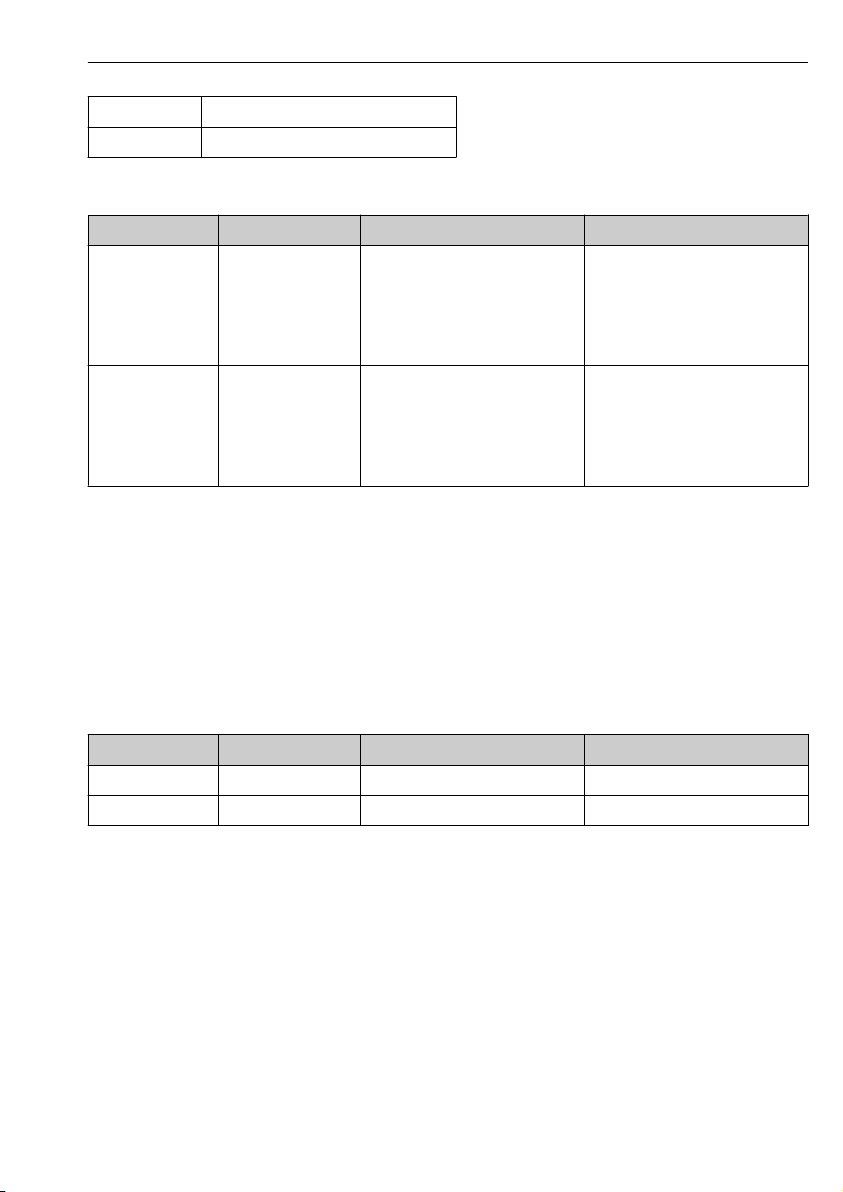
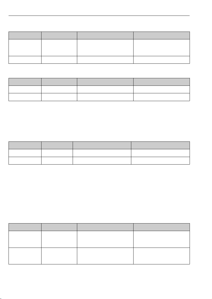
5.4 Post-connection check
Device condition and specifications Action
Are the sensor, assembly, or cables free from damage on the
outside?
Electrical connection Action
Are the mounted cables strain-relieved and not twisted?
Is a sufficient length of the cable cores stripped, and are the
cores positioned in the terminal correctly?
Are all the screw terminals properly tightened?
Are all cable entries mounted, tightened and leak-tight? In the case of lateral cable entries:
Are all cable entries installed downwards or mounted laterally?
30 Endress+Hauser
Perform a visual inspection.
‣
Untwist the cables.
‣
Pull gently to check they are seated correctly.
‣
Tighten the screw terminals.
‣
Point cable loops downward so that water can
‣
drip off.
Page 31

Indumax CLS50D/CLS50 Commissioning
6 Commissioning
Prior to initial commissioning, ensure that:
• The sensor is correctly installed
• The electrical connection is correct
If using an assembly with automatic cleaning function:
Check that the cleaning medium (water or air, for example) is connected correctly.
‣
WARNING
L
Escaping process medium
Risk of injury from high pressure, high temperatures or chemical hazards!
Before applying pressure to an assembly with cleaning system, ensure that the system has
‣
been connected correctly.
If you cannot reliably establish the correct connection, do not install the assembly in the
‣
process.
At the transmitter, enter all the settings specific to the parameters and measuring point.
‣
The measuring point is then ready to measure.
Following commissioning, the sensor must be serviced at regular intervals, as only then
can reliable measurement be guaranteed.
Operating Instructions for the transmitter used, such as BA01245C if using the Liquiline
CM44x or CM44xR.
7 Maintenance
WARNING
L
Thiocarbamide
Harmful if swallowed! Limited evidence of carcinogenicity! Possible risk of harm to the unborn
child! Dangerous for the environment with long-term effects!
Wear protective goggles, protective gloves and appropriate protective clothing.
‣
Avoid all contact with the eyes, mouth and skin.
‣
Avoid discharge into the environment.
‣
Clean away fouling on the sensor as follows depending on the type of fouling:
1. Oily and greasy films:
Clean with fat solvent, e.g. alcohol, or hot water and agents containing surfactants
(alkaline) (e.g. dishwashing detergent).
2. Lime and metal hydroxide buildup and low solubility (lyophobic) organic buildup:
Dissolve buildup with diluted hydrochloric acid (3 %) and then rinse thoroughly with
plenty of clear water.
Endress+Hauser 31
Page 32

Repair Indumax CLS50D/CLS50
150
280, 285, 286
260, 270
250, 255
3. Sulfidic buildup (from flue gas desulfurization or wastewater treatment plants):
Use a mixture of hydrochloric acid (3 %) and thiocarbamide (commercially available)
and then rinse thoroughly with plenty of clear water.
4. Buildup containing proteins (e.g. food industry):
Use a mixture of hydrochloric acid (0.5 %) and pepsin (commercially available) and then
rinse thoroughly with plenty of clear water.
5. Readily soluble biological buildup:
Rinse with pressurized water.
After cleaning, rinse the sensor thoroughly with water.
8 Repair
8.1 Spare parts
Item No. Spare parts kit Order No.
150, 255 CHEMRAZ seal kit
150, 250 VITON seal kit
260 PTFE disk kit for DN 50 71086372
270 PTFE disk kit for ANSI 2" and JIS 10K 50A 71086374
150, 280 Fixed flange kit, DN 50, stainless steel 1.4404 (AISI
150, 285 Fixed flange kit, ANSI 2", stainless steel 1.4404 (AISI
150, 286 Fixed flange kit, JIS, stainless steel 1.4404 (AISI 316L)
A0025483
• Nut (item 150)
• CHEMRAZ O-ring, 2 pcs. (item 255)
• Nut (item 150)
• VITON O-ring, 3. pcs., (item 250)
316L)
• Nut (item 150)
• Flange DN 50 (item 280)
316L)
• Nut (item 150)
• Flange ANSI 2" (item 285)
• Nut (item 150)
• Flange DN 50 (item 286)
71086368
71086369
51500525
51500527
51500934
32 Endress+Hauser
Page 33

Indumax CLS50D/CLS50 Accessories
291, 292, 293
150
287, 288, 289
260, 270
250, 255
Item No. Spare parts kit Order No.
150, 288,
292
150, 287,
291
150, 289,
293
A0025484
Lap joint flange kit, ANSI 2", PVDF
• Nut (item 150)
• Flange ANSI 2", PVDF (item 288)
• Lap joint flange, UP-GF (item 292)
Lap joint flange kit, DN 50, PVDF
• Nut (item 150)
• Flange DN 50, PVDF (item 287)
• Lap joint flange, UP-GF (item 291)
Lap joint flange kit, JIS, PVDF
• Nut (item 150)
• Flange JIS, PVDF (item 289)
• Lap joint flange, UP-GF (item 293)
51500937
51500936
51500935
8.2 Return
The product must be returned if repairs or a factory calibration are required, or if the wrong
product was ordered or delivered. As an ISO-certified company and also due to legal
regulations, Endress+Hauser is obliged to follow certain procedures when handling any
returned products that have been in contact with medium.
To ensure the swift, safe and professional return of the device:
‣
8.3 Disposal
The device contains electronic components. The product must be disposed of as electronic
waste.
‣
9 Accessories
The following are the most important accessories available at the time this documentation
was issued.
‣
Endress+Hauser 33
Refer to the website www.endress.com/support/return-material for information on the
procedure and conditions for returning devices.
Observe the local regulations.
For accessories not listed here, please contact your Service or Sales Center.
Page 34

Accessories Indumax CLS50D/CLS50
9.1 Measuring cable
9.1.1 For CLS50D Memosens data cable CYK11
• Extension cable for digital sensors with Memosens protocol
• Product Configurator on the product page: www.endress.com/cyk11
Technical Information TI00118C
9.1.2 For CLS50
Measuring cable CLK6
• Extension cable for inductive conductivity sensors, for extension via VBM junction box
• Sold by the meter, order number: 71183688
VBM
• Junction box for cable extension
• 10 terminal strips
• Cable entries: 2 x Pg 13.5 or 2 x NPT ½"
• Material: aluminum
• Degree of protection: IP 65
• Order numbers
• Cable entries Pg 13.5 : 50003987
• Cable entries NPT ½": 51500177
9.2 Assemblies
Dipfit CLA111
• Immersion assembly for open and closed vessels with flange DN 100
• Product Configurator on the product page: www.products.endress.com/cla111
Technical Information TI00135C
Dipfit CLA140
• For the CLS50/CLS50D inductive sensor
• Immersion assembly with flange connection for very demanding processes
• Product Configurator on the product page: www.products.endress.com/cla140
Technical Information TI00196C
Flexdip CYA112
• Immersion assembly for water and wastewater
• Modular assembly system for sensors in open basins, channels and tanks
• Material: PVC or stainless steel
• Product Configurator on the product page: www.endress.com/cya112
Technical Information TI00432C
34 Endress+Hauser
Page 35

Indumax CLS50D/CLS50 Technical data
9.3 Calibration solutions
Conductivity calibration solutions CLY11
Precision solutions referenced to SRM (Standard Reference Material) by NIST for qualified
calibration of conductivity measuring systems in accordance with ISO 9000
• CLY11-B, 149.6 μS/cm (reference temperature 25 °C (77 °F)), 500 ml (16.9 fl.oz)
Order No. 50081903
• CLY11-C, 1.406 mS/cm (reference temperature 25 °C (77 °F)), 500 ml (16.9 fl.oz)
Order No. 50081904
• CLY11-D, 12.64 mS/cm (reference temperature 25 °C (77 °F)), 500 ml (16.9 fl.oz)
Order No. 50081905
• CLY11-E, 107.00 mS/cm (reference temperature 25 °C (77 °F)), 500 ml (16.9 fl.oz)
Order No. 50081906
Technical Information TI00162C
10 Technical data
10.1 Input
10.1.1 Measured variables
• Conductivity
• Temperature
10.1.2 Measuring range
Conductivity
Temperature -20 to +180 °C (-4 to +350 °F)
10.1.3 Cell constant
k = 1.98 cm
10.1.4 Measuring frequency
2 kHz
10.1.5 Temperature measurement
CLS50D
Pt1000 (Class A according to IEC 60751)
CLS50
Pt100 (Class A according to IEC 60751)
Endress+Hauser 35
–1
2 μS/cm to 2000 mS/cm (uncompensated)
Page 36

Technical data Indumax CLS50D/CLS50
10.2 Performance characteristics
10.2.1 Conductivity response time
t95 ≤ 2 s
10.2.2 Temperature response time
PEEK version: t90 ≤ 7 min
PFA version: t90 ≤ 11 min
10.2.3 Maximum measured error
-20 to 100 °C (-4 to 212 °F): ±(5 μS/cm + 0.5 % of reading)
> 100 °C (212 °F): ±(10 μS/cm + 0.5 % of reading)
10.2.4 Repeatability
For T < 100 °C (212 °F): 0.2 % of reading + 1 µS/cm
For T > 100 °C (212 °F): 0.2 % of reading + 2 µS/cm
10.2.5 Linearity
1.9 % (only applies in the 1 to 20 mS/cm measuring range)
10.3 Environment
10.3.1 Ambient temperature
CLS50D
-10 to +60 °C (+10 to +140 °F)
CLS50
-10 to +70 °C (+10 to +160 °F)
10.3.2 Storage temperature
-20 to +80 °C (0 to +180 °F)
10.3.3 Degree of protection
IP 68 / NEMA type 6 (sensor in installed state with genuine seal)
36 Endress+Hauser
Page 37

Indumax CLS50D/CLS50 Technical data
10.4 Process
10.4.1 Process temperature
Sensor
material
PEEK –20 to 125 °C
PFA –20 to 110 °C
CLS50D-*1/2
Without flange
(-4 to 260 °F)
(-4 to 230 °F)
CLS50D-*3/4/5/6/8
DN50, ANSI 2"
–20 to 125 °C
(-4 to 260 °F)
–20 to 110 °C
(-4 to 230 °F)
CLS50D-*7
JIS
–20 to 125 °C
(-4 to 260 °F)
–20 to 110 °C
(-4 to 230 °F)
CLS50D-*A/B/C
PVDF lap joint flange
–20 to 125 °C
(-4 to 260 °F)
–20 to 110 °C
(-4 to 230 °F)
CLS50
Sensor
material
PEEK –20 to 180 °C
PFA –20 to 125 °C
CLS50-*1/2
Without flange
(-4 to 360 °F)
(-4 to 260 °F)
CLS50-*3/4/5/6/8
DN50, ANSI 2"
–20 to 180 °C
(-4 to 360 °F)
–20 to 125 °C
(-4 to 260 °F)
CLS50-*7
JIS
–20 to 180 °C
(-4 to 360 °F)
–20 to 125 °C
(-4 to 260 °F)
CLS50-*A/B/C
PVDF lap joint flange
–20 to 125 °C
(-4 to 260 °F)
–20 to 125 °C
(-4 to 260 °F)
10.4.2 Process pressure (absolute)
Max. 21 bar (305 psi), depending on the sensor version, see pressure-temperature ratings
Endress+Hauser 37
Page 38

Technical data Indumax CLS50D/CLS50
21
17
11
–20 +20
125
1
2
3
4
[°C]
[bar]
[°F]
[psi]
247
160
–4
257+68
5
110
230
0
+23
1006040 80
Ex
PFA
T
p (abs.)
1
305
15
10.4.3 Temperature/pressure ratings
CLS50D
A0024981
11 Pressure temperature ratings CLS50D
1 PEEK sensor, without a flange
2 PFA sensor, without a flange (blue line)
3 PEEK or PFA sensor, with DN50/ANSI 2" flange (red line)
4 PEEK or PFA sensor, with JIS flange
5 PEEK or PFA sensor, with PVDF lap joint flange (green line)
38 Endress+Hauser
Page 39

Indumax CLS50D/CLS50 Technical data
21
17
11
–20 +20
125
180
1
2
3
4
[°C]
[bar]
[°F]
[psi]
247
160
–4
257
356
+68
5
0
+23
10060 140 16040 80
6
T
p (abs.)
305
1
15
CLS50
A0024979
12 Pressure-temperature ratings for CLS50
1 PEEK sensor, without a flange
2 PFA sensor, without a flange or with DN50/ANSI 2" flange (blue line)
3 PEEK sensor, with DN50/ANSI 2" flange (red line)
4 PFA sensor, with JIS flange (black line)
5 PEEK or PFA sensor, with PVDF lap joint flange (green line)
6 PEEK sensor, with JIS flange (gray line)
10.5 Mechanical construction
10.5.1 Weight
Approx. 0.65 kg (1.43 lbs)
10.5.2 Materials
Sensor PEEK, PFA (depending on version)
Sensor seal VITON, CHEMRAZ (depending on version)
Endress+Hauser 39
Page 40

Technical data Indumax CLS50D/CLS50
d
2
a
Ø k
D
b
d
2
a
Ø k
D
b
1
2
Process connections
G¾ CLS50D-*1B/C**: PEEK GF30
NPT 1" PEEK
Fixed flange Stainless steel 1.4404 (AISI 316L)
Sealing disk GYLON (PTFE ceramic-filled)
Lap joint flange PP-GF
Flange combined with lap joint flange PVDF
CLS50D-*1D**: stainless steel (AISI 316Ti)
CLS50-*1A*: stainless steel 1.4571 (AISI 316Ti)
CLS50-*1B/C/1/2/3: PEEK GF30
CLS50-*1B/C5/6: stainless steel 1.4571 (AISI 316Ti)
10.5.3 Process connections
• G¾ thread
• NPT 1" thread
• Lap joint flange EN 1092 DN50 PN10
• Lap joint flange ANSI 2" 150 lbs
• Lap joint flange JIS 10K 50A
• Flange EN 1092-1 DN50 PN16
• Flange ANSI 2" 300 lbs
• Flange JIS 10K 50A
Flange dimensions
13 Flange dimensions
1 Lap joint flange (PP-GF)
2 Fixed flange (stainless steel)
40 Endress+Hauser
A0024986
Page 41

Indumax CLS50D/CLS50 Technical data
Dimensions in mm
Lap joint flange PP-GF DN50 PN10 ANSI 2" 150 lbs JIS 10K 50A
D 165 165 152
Ø k 125 121 120
d
2
4 x 18 8 x 19 4 x 19
b 18 18 18
a 78 78 78
Screws M16 M16 M16
Dimensions in mm
Fixed flange SS 316 L DN50 PN10 ANSI 2" 300 lbs JIS 10K 50A
D 165 165.1 155
Ø k 125 127 120
d
2
b 18 22.2 16
a 27 27 27
Screws M16 M16 M16
4 x 18 8 x 19 4 x 19
10.5.4 Chemical resistance
Medium Concentration PEEK PFA CHEMRAZ VITON
Sodium hydroxide
solution
NaOH
Nitric acid
HNO
3
Phosphoric acid
H3PO
4
Sulfuric acid
H2SO
4
Hydrochloric acid
HCl
Endress+Hauser 41
0 to 50 % 20 to 100 °C
(68 to 212 °F)
0 to 10 % 20 to 100 °C
(68 to 212 °F)
20 to 50 °C
(68 to 122 °F)
20 to 80 °C
(68 to 176 °F)
0 to 40 % 20 °C (68 °F) 20 to 60 °C
(68 to 140 °F)
0 to 80 % 20 to 100 °C
(68 to 212 °F)
0 to 2.5 % 20 to 80 °C
(68 to 176 °F)
20 to 60 °C
(68 to 140 °F)
20 to 100 °C
(68 to 212 °F)
0 to 30 % 20 °C (68 °F) 20 to 100 °C
(68 to 212 °F)
0 to 5 % 20 to 100 °C
(68 to 212 °F)
0 to 10 % 20 to 100 °C
(68 to 212 °F)
20 to 80 °C
(68 to 176 °F)
20 to 80 °C
(68 to 176 °F)
0 to 150 °C
(32 to 302 °F)
0 to 150 °C
(32 to 302 °F)
0 to 150 °C
(32 to 302 °F)
0 to 150 °C
(32 to 302 °F)
0 to 150 °C
(32 to 302 °F)
0 to 150 °C
(32 to 302 °F)
0 to 150 °C
(32 to 302 °F)
0 to 150 °C
(32 to 302 °F)
Not suitable
0 to 120 °C
(32 to 248 °F)
0 to 120 °C
(32 to 248 °F)
0 to 120 °C
(32 to 248 °F)
0 to 120 °C
(32 to 248 °F)
0 to 120 °C
(32 to 248 °F)
0 to 120 °C
(32 to 248 °F)
0 to 120 °C
(32 to 248 °F)
Page 42

Index Indumax CLS50D/CLS50
Index
A
Accessories ..................... 33
Air set ........................ 20
Ambient temperature ............... 36
Approvals ...................... 18
Marine .....................19
Assembly ...................... 24
C
Cable extension ...................30
Calibration solutions ................35
Cell constant .................... 35
Certificates ..................... 18
Check
Connection .................. 30
Installation .................. 24
Chemical resistance ................ 41
Cleaning agent ................... 31
Conductivity response time ............36
Connection
Check ..................... 30
Ensuring the degree of protection ..... 30
Connection conditions ...............25
D
Declaration of Conformity ........... 2, 18
Degree of protection ................36
Ensuring ....................30
Designated use ....................9
Direct connection to transmitter .........29
Disposal ....................... 33
E
Electrical connection ................24
Environment .................... 36
EU Declaration of Conformity ........... 2
Ex approvals .................... 18
F
Flange ........................ 21
H
Hazardous areas .................. 10
Input .........................35
Installation ..................... 19
Installation conditions ...............19
Installation factor ................. 19
Installation position ................ 19
Interpreting the order code ............ 17
L
Linearity .......................36
M
Maintenance .................... 31
Manufacturer's address .............. 17
Marine ........................19
Materials ...................... 39
Maximum measured error ............ 36
Measured variables ................ 35
Measuring frequency ............... 35
Measuring ranges ................. 35
Mechanical construction ............. 39
N
Nameplate ..................... 17
O
Operational safety ................. 10
P
Performance characteristics ........... 36
Post-installation check .............. 24
Pressure/temperature ratings .......... 38
Process ........................37
Process connections ................ 40
Process pressure .................. 37
Process temperature ................37
Product identification .............14, 17
Product page .................... 17
Product safety ................... 10
R
Repair ........................ 32
Repeatability .................... 36
Requirements for personnel ............ 9
Return ........................ 33
I
Incoming acceptance ................14
42 Endress+Hauser
Page 43

Indumax CLS50D/CLS50 Index
S
Safety
Electrical equipment in hazardous areas . 10
Safety instructions ..................9
Scope of delivery .................. 17
Sensor
Connecting .................. 29
Connection in hazardous area ....... 25
Mounting ................... 21
State-of-the-art technology ............10
Storage temperature ................36
Symbols ........................ 7
T
Technical data ................... 35
Environment ................. 36
Mechanical construction .......... 39
Performance characteristics ........ 36
Process .....................37
Temperature measurement ............35
Temperature response time ............36
Temperature/pressure ratings .......... 38
Type code ...................... 14
U
Use ...........................9
W
Warnings ....................... 7
Weight ........................39
Wiring ........................29
Workplace safety .................. 9
Endress+Hauser 43
Page 44

*71464663*
71464663
www.addresses.endress.com
 Loading...