

Page 1
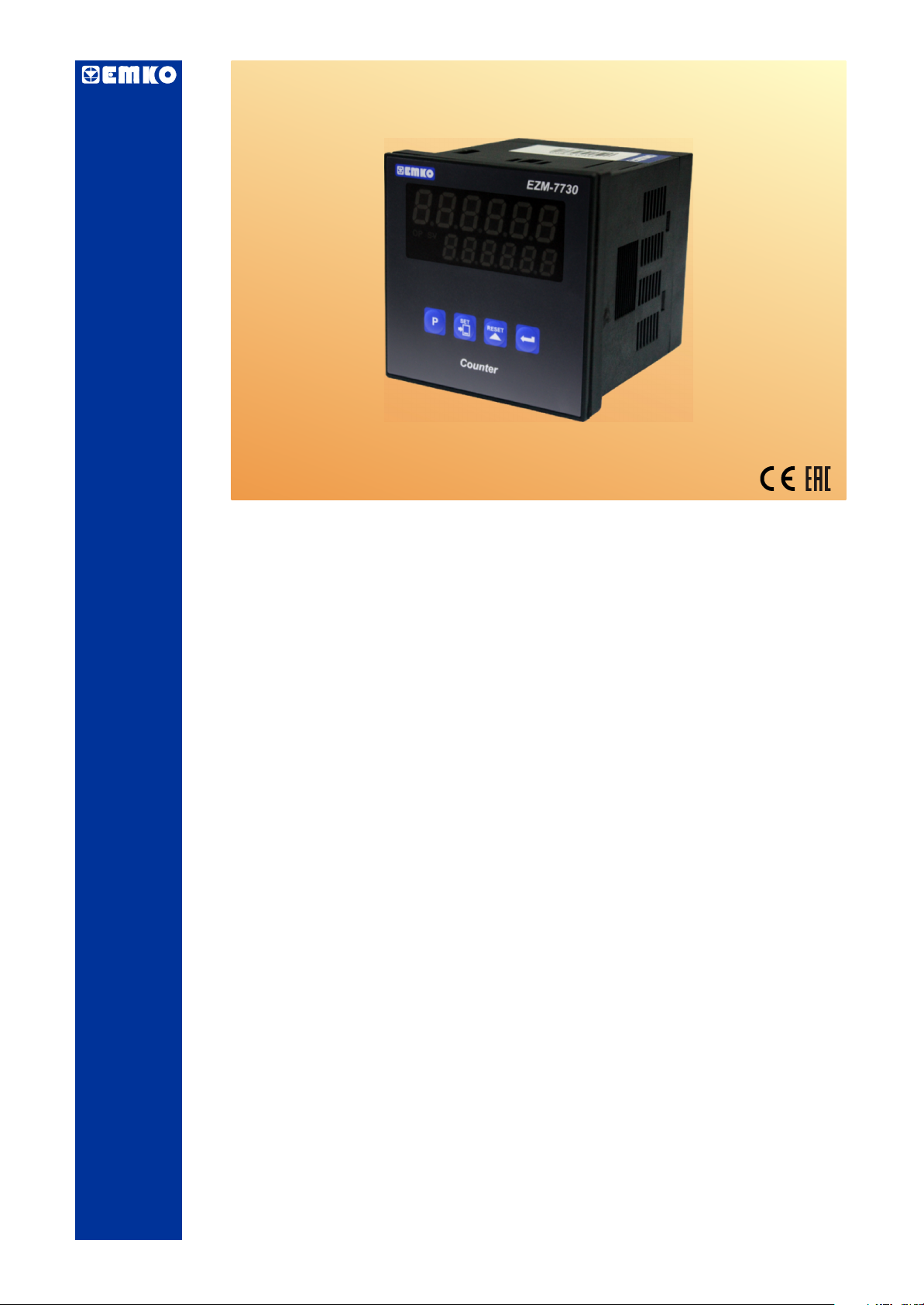
EZM-7730 72 x 72 DIN Size
Universal Input Programmable Counter
-
6 digits Process (PV) and 6 digits Set (SV) Value Display
- Operation with 1 Set Value
- Reset , Pause and ChA-ChB Counting Inputs
-
Operation with Automatic and Manual Reset
-
NPN/PNP Type Operation
- INC , DEC , INC / INC , INC / DEC , UP / DOWN , x1 / x2 / x4
Counting with Phase Shifting Property in Counter Function
- Multiplication Coefficient and Decimal Point Position
EZM-7730 72x72 DIN SIZE Programmable Counter
Introduction Manual. ENG EZM-7730 02 V02 08/14
Page 2

ABOUT INSTRUCTION MANUAL
Instruction manual of EZM-7730 Programmable Counter consists of two main sections.
Explanation of these sections are below. Also, there are other sections which include order
information and technical specifications of the device. All titles and page numbers in instruction
manual are in “CONTENTS” section. User can reach to any title with section number.
Installation:
In this section, physical dimensions of the device, panel mounting, electrical wiring,
module mounting in the device, physical and electrical installation of the device to the system are
explained.
Operation and Parameters:
In this section, user interface of the device, how to access to the parameters, description
of parameters are explained.
Also in these sections, there are warnings to prevent serious injury while doing the
physical and electrical mounting or using the device.
Explanation of the symbols which are used in these sections are given below.
c
a
i
This symbol is used for safety warnings. User must pay attention to these
warnings.
This symbol is used to determine the dangerous situations as a result of an electric
shock. User must pay attention to these warnings definitely.
This symbol is used to determine the important notes about functions and usage of
the device.
2
Page 3

CONTENTS
1.PREFACE..................................................................................................................
1.1 GENERAL SPECIFICATIONS
1.2 ORDERING INFORMATION
1.3 WARRANTY
1.4 MAINTENANCE
Page 5
2.INSTALLATION.........................................................................................................
2.1 GENERAL DESCRIPTION
2.2 DIMENSIONS
2.3 PANEL CUT-OUT
2.4 ENVIRONMENTAL RATINGS
2.5 PANEL MOUNTING
2.6 INSTALLATION FIXING CLAMP
2.7 REMOVING FROM THE PANEL
3.ELECTRICAL WIRINGS...........................................................................................
3.1 TERMINAL LAYOUT AND CONNECTION INSTRUCTION
3.2 ELECTRICAL WIRING DIAGRAM
3.3 VIEW OF DEVICE LABEL
3.4 CONNECTION OF DEVICE SUPPLY VOLTAGE INPUT
3.5 COUNTING INPUT CONNECTION
3.5.1 PROXIMITY & SWITCH CONNECTION
3.5.2 INCREMENTAL ENCODER & SWITCH CONNECTION
3.5.3 SWITCH CONNECTION
3.6 RELAY OUTPUT WIRING DIAGRAM
3.7 GALVANIC ISOLATION TEST VALUES OF EZM-7730 PROGRAMMABLE
COUNTER
Page 7
Page 12
4.DEFINITION OF FRONT PANEL AND ACCESSING TO THE SET
PARAMETERS............................................................................................................
4.1 DEFINITION OF FRONT PANEL
4.2 POWER ON OBSERVATION OF EZM - 7730 PROGRAMMABLE
COUNTER AND SOFTWARE REVISION ON THE DISPLAY
4.3 ADJUSTMENT OF SET VALUE
4.4
RESETTING COUNT VALUE
4.5
ACCESSING TO THE PROGRAM PARAMETERS
5.PROGRAM PARAMETERS......................................................................................
6.
FAILURE MESSAGES IN EZM-7730 PROGRAMMABLE COUNTER ...................
7.SPECIFICATIONS ....................................................................................................
8.OTHER INFORMATIONS..........................................................................................
Page 20
Page 29
Page 46
Page 47
Page 48
3
Page 4

EU DECLARATION OF CONFORMITY
Manufacturer’s Name : EMKO ELEKTRONIK A.S.
Manufacturer’s Address : DOSAB, Karanfil Sk., No:6,
16369 Bursa, TURKEY
The manufacturer hereby declares that the product:
Product Name : Programmable Counter
Type Number : EZM-7730
Product Category : Electrical equipment for measurement, control and
laboratory use
Conforms to the following directives :
2006 / 95 / EC The Low Voltage Directive
2004 / 108 / EC The Electromagnetic Compatibility Directive
has been designed and manufactured to the following specifications:
EN 61000-6-4:2007 EMC Generic Emission Standard for Industrial Environments
EN 61000-6-2:2005 EMC Generic Immunity Standard for Industrial Environments
EN 61010-1:2001 Safety Requirements for electrical equipment for measurement, control
and laboratory use
When and Where Issued Authorized Signature
th
16 October 2009 Name : Serpil YAKIN
Bursa-TURKEY Position : Quality Manager
4
Page 5
1.Preface
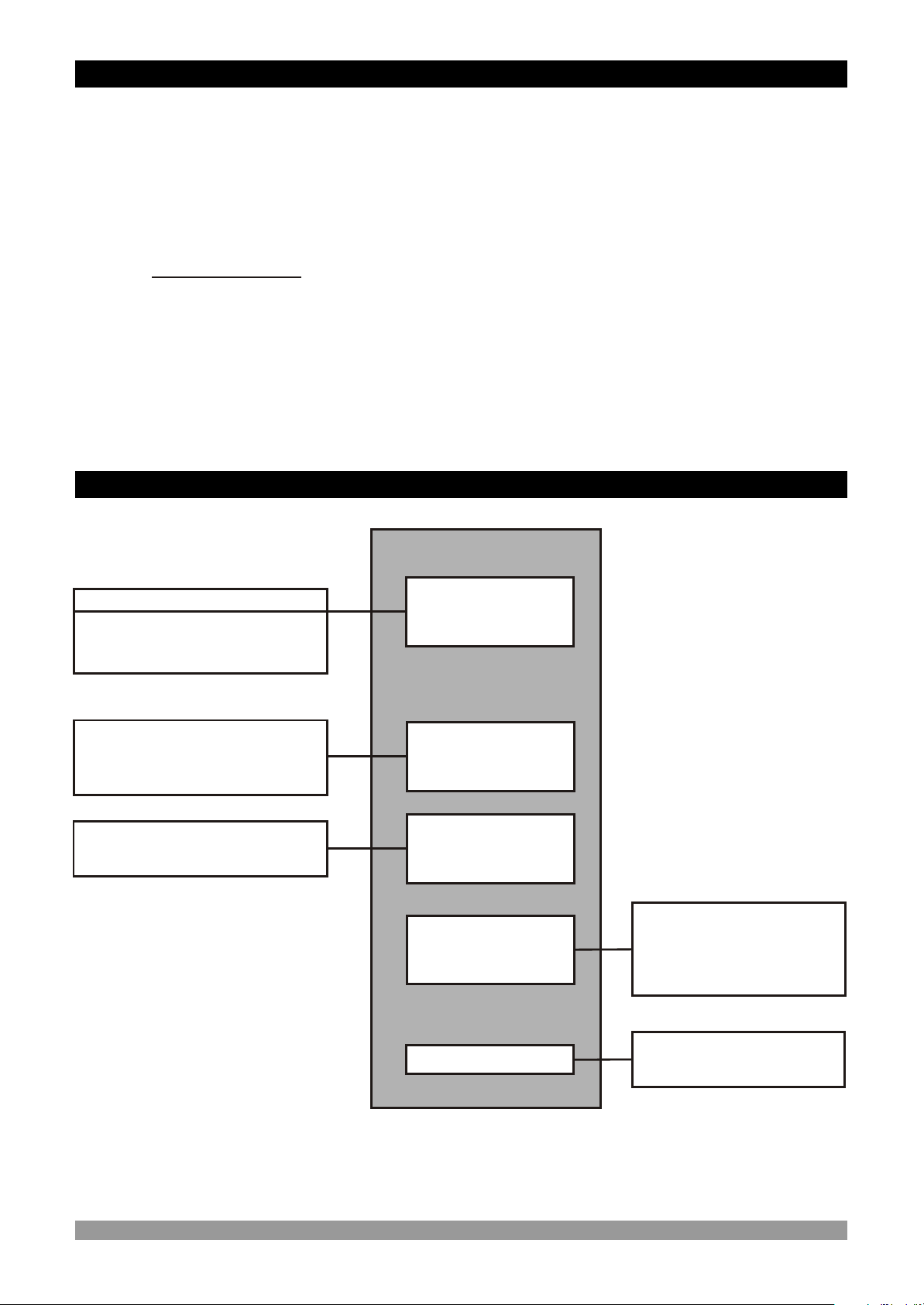
EZM Series Programmable Counter can be used in package machines, production and
quality control rollers, in cutting and processing machine of glass, plastic, marble, sheet, iron,
fabric all measuring and controlling of dimension, productivity, and can be adapted easily to all
mechanical construction and automation system.
Some application fields which they are used are below:
Application Fields
Package machines,
Quality Control rollers,
Filling Systems,
Tool Benchs,
Measuring Dimension and Control Automation,
In Cutting and Processing machine of glass, plastic, marble, sheet, iron and fabric
Building Automation.
Production bands
1.1 General Specifications
Standart
230 V V 50/60Hz
Optional Supply Input
115V V 50/60Hz, 24V V 50/60Hz
24 V Z
Switch
Proximity Sensor(NPN,PNP)
Optic Sensor
Encoder
Switch
Proximity Sensor(NPN,PNP)
Optic Sensor(NPN,PNP)
EZM-7730
Supply Voltage
Input
Counting Inputs
(Ch A, Ch B)
Reset and Pause
Inputs
Sensor Voltage
Output
Switch
Proximity Sensor
(NPN,PNP)
Optic Sensor
Encoder
Standart
Output
Control Output(Relay)
5
Page 6

1.2 Ordering Information
A BC D E FG HI //U V W Z/
EzM-7730 ( 72x72 DIN)
/
100 0 0
0 0 0
Supply VoltageA
24 V V (-%15;+%10) 50/60Hz or 24 VZ (-%15;+%10)
2
24 V V (-%15;+%10) 50/60Hz
3
4
115 V V (-%15;+%10) 50/60Hz
230V V (-%15;+%10) 50/60Hz
5
9
Customer (Maximum 240V V (-%15;+%10))50/60Hz
Output-1E
Relay Output (5A @ 250 V V) Rezistive Load
1
00 00
All order information of EZM-7730
Programmable Counter are given on the
table at left. User may form appropriate
device configuration from information and
codes that at the table and convert it to the
ordering codes.
Supply voltage must be determined
for your system.
Please fill the order code blanks
according to your needs.
Please contact us, if your needs are
out of the standards.
V Symbol means Vac
Z Symbol means Vdc
c
W Symbol means Vac and Vdc
can be applied.
1.3 Warranty
EMKO Elektronik warrants that the equipment delivered is free from defects in material and
workmanship. This warranty is provided for a period of two years. The warranty period starts from
the delivery date. This warranty is in force if duty and responsibilities which are determined in
warranty document and instruction manual performs by the customer completely.
1.4 Maintenance
Repairs should only be performed by trained and specialized personnel. Cut power to the device
before accessing internal parts.
Do not clean the case with hydrocarbon-based solvents (Petrol, Trichlorethylene etc.). Use of
these solvents can reduce the mechanical reliability of the device. Use a cloth dampened in ethyl
alcohol or water to clean the external plastic case.
6
Page 7

2.Installation
Before beginning installation of this product, please read the instruction
manual and warnings below carefully.
c
In package ,
- One piece unit
- Two pieces mounting clamps
- One piece instruction manual
A visual inspection of this product for possible damage occured during shipment is
recommended before installation. It is your responsibility to ensure that qualified
mechanical and electrical technicians install this product.
If there is danger of serious accident resulting from a failure or defect in this unit, power
off the system and separate the electrical connection of the device from the system.
The unit is normally supplied without a power switch or a fuse. Use power switch and fuse
as required.
Be sure to use the rated power supply voltage to protect the unit against damage and to
prevent failure.
Keep the power off until all of the wiring is completed so that electric shock and trouble
with the unit can be prevented.
Never attempt to disassemble, modify or repair this unit. Tampering with the unit may
results in malfunction, electric shock or fire.
Do not use the unit in combustible or explosive gaseous atmospheres.
During the equipment is putted in hole on the metal panel while mechanical installation
some metal burrs can cause injury on hands, you must be careful.
Montage of the product on a system must be done with it’s fixing clamps. Do not do the
montage of the device with inappropriate fixing clamp. Be sure that device will not fall
while doing the montage.
It is your responsibility if this equipment is used in a manner not specified in this
instruction manual.
7
Page 8
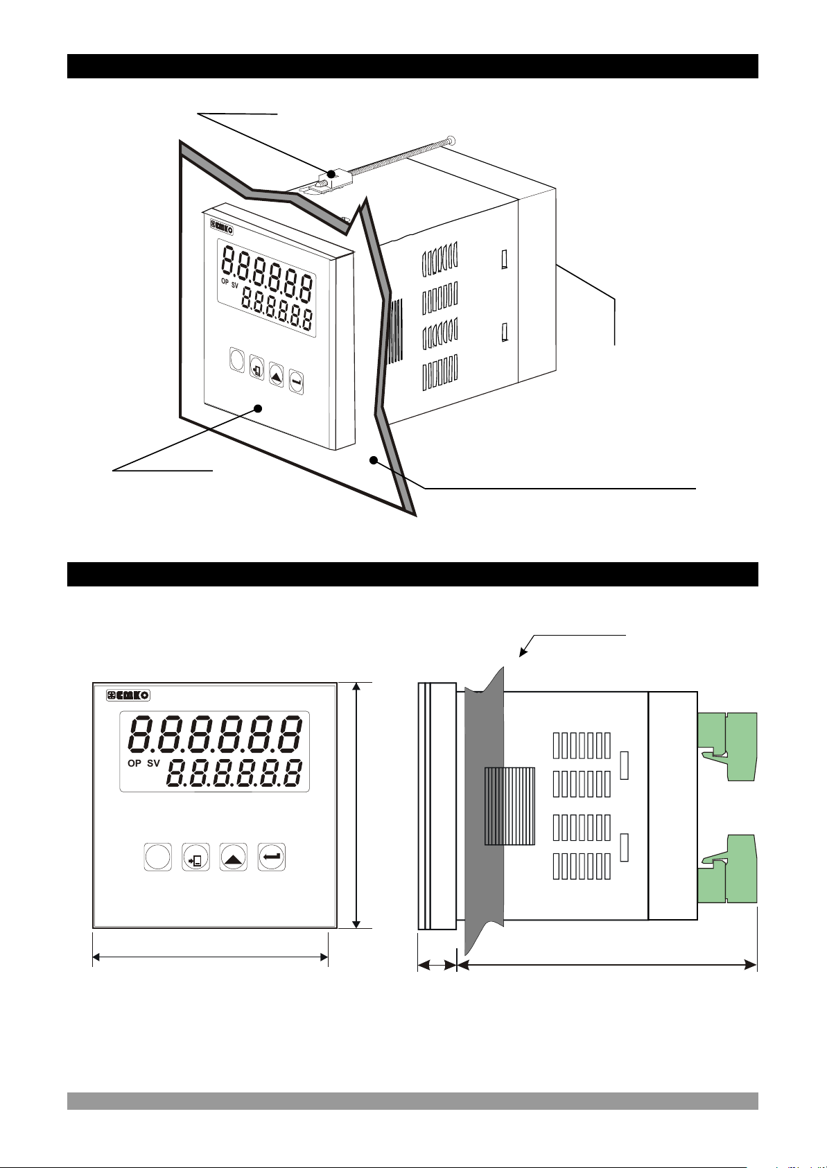
2.1 General Description
Mounting Clamp
O
P
VS
O
2
S
2
Z
- 7
7
3
0E M
Front Panel
IP65 protection
2.2 Dimensions
P
S
E
T
R
EET
S
C
o
u
ne
t
r
EZM-7730
Device Label
Panel surface
(maximum thickness 15 mm / 0.59 inch)
Maximum 15 mm / 0.59 inch
SV
OP
S2
O2
RESET
SET
P
Counter
72 mm / 2.83 inch
72 mm / 2.83 inch
11.5 ± 1 mm / 0.45 inch
84 mm / 3.31 inch
8
Page 9
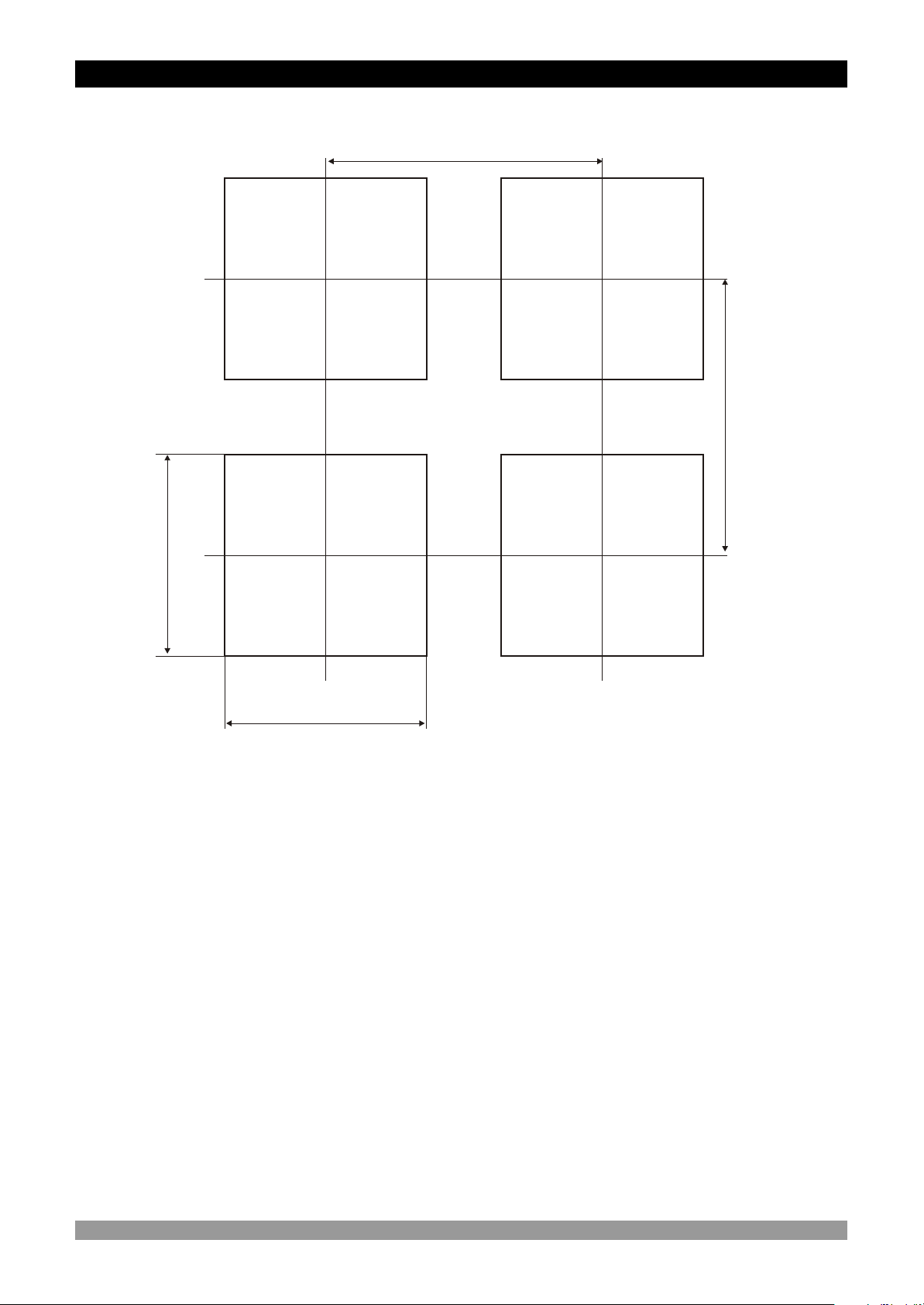
2.3 Panel Cut-out
97 mm / 3.82 inch (min)
97 mm / 3.82 inch (min)
69 mm / 2.72 inch
69 mm / 2.72 inch
10
9
Page 10
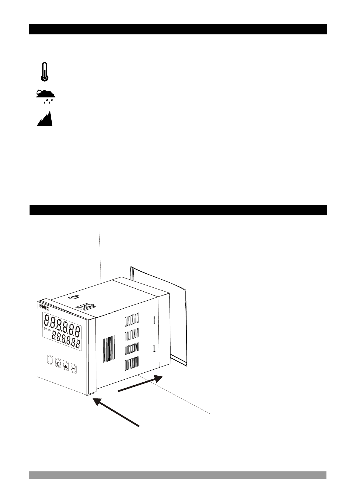
2.4 Environmental Ratings
Operating Conditions
Operating Temperature : 0 to 50 °C
Max. Operating Humidity : 90% Rh (non-condensing)
Altitude : Up to 2000m.
Forbidden Conditions:
Corrosive atmosphere
Explosive atmosphere
c
Home applications (The unit is only for industrial applications)
2.5 Panel Mounting
E
Z
-
7
7M
3
0
OP
S
V
O
2
S2
P
S
E
T
R
E
S
E
T
C
o
nt
e
ru
1-Before mounting the device in
your panel, make sure that the
cut-out is the right size.
1
2-Check front panel gasket
position
3-Insert the device through the
cut-out. If the mounting clamps
are on the unit, put out them
before inserting the unit to the
panel.
c
3
2
During installation into a metal panel, care should be taken to avoid injury from
metal burrs which might be present. The equipment can loosen from vibration
and become dislodged if installation parts are not properly tightened. These
precautions for the safety of the person who does the panel mounting.
10
Page 11
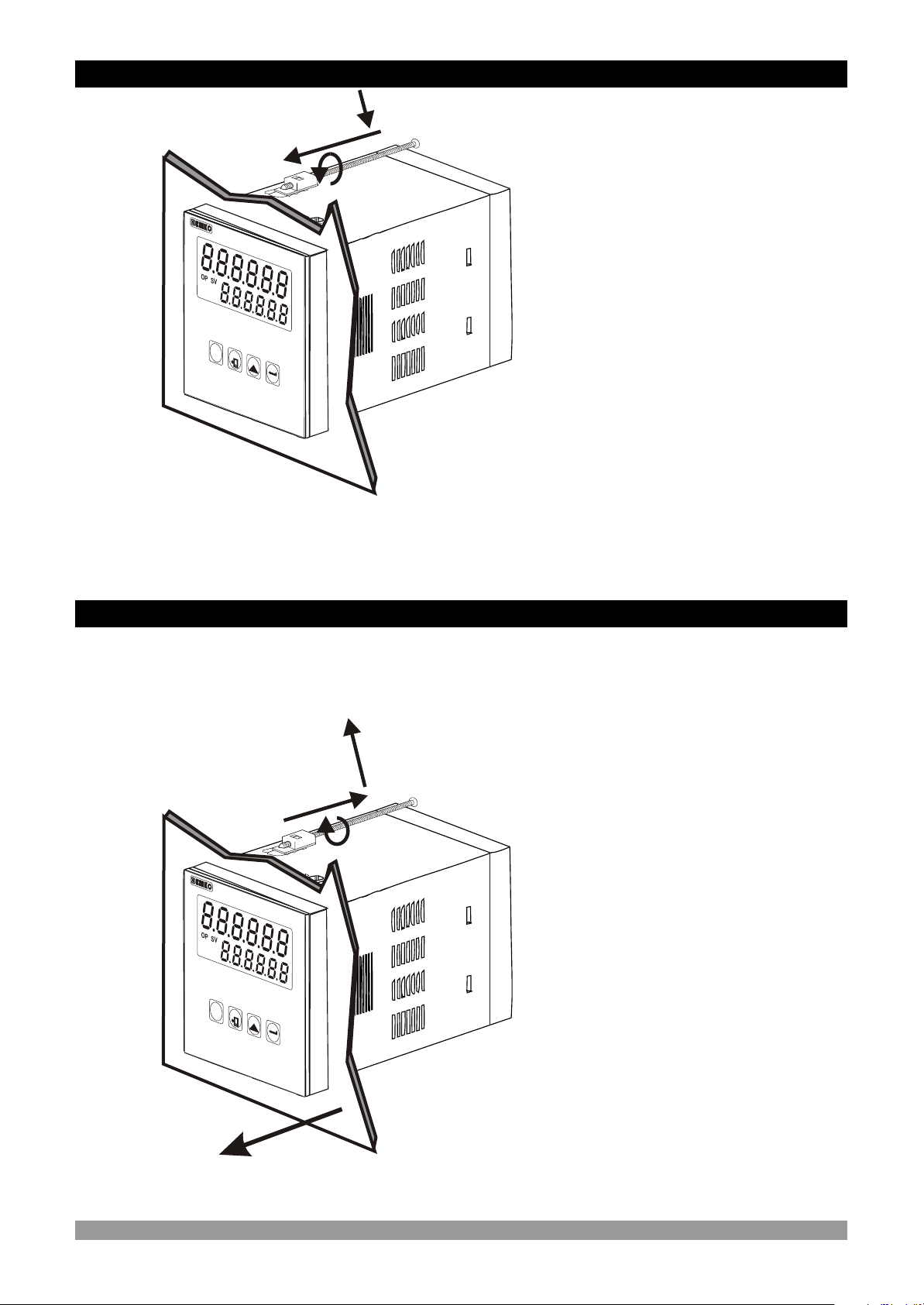
2.6 Installation Fixing Clamp
1
c
2
mounting.
1-Insert the unit in the panel cut-out
from the front side.
The unit is designed for panel
EZ
M
-
7
730
OP
SV
O
2
2S
2- Insert the mounting clamps to the
holes that located top and bottom
sides of device and screw up the
P
S
E
T
R
ES
E
T
C u
o
n
te
r
fixing screws until the unit
completely immobile within the
panel
Montage of the unit to a system must be done with it’s own fixing clamps. Do not
do the montage of the device with inappropriate fixing clamps. Be sure that
device will not fall while doing the montage.
2.7 Removing from the Panel
Before starting to remove the unit from panel, power off the unit and the related
system.
c
EM
Z -7
7
3
0
O
P
S
V
O2
S
2
P
S
ET
RE
S
E
T
nCou
t
e
r
2
1
1-Loosen the screws.
2-Pull mounting clamps from top
and bottom fixing sockets.
3-Pull the unit through the front
side of the panel
3
11
Page 12
3.Electrical Wirings
You must ensure that the device is correctly configured for your application.
Incorrect configuration could result in damage to the process being controlled,
and/or personal injury. It is your responsibility, as the installer, to ensure that
c
c
the configuration is correct.
Parameters of the device has factory default values. These parameters must be
set according to the system’s needs.
Only qualified personnel and technicians should work on this equipment. This
equipment contains internal circuits with voltage dangerous to human life.
There is severe danger for human life in the case of unauthorized intervention.
Be sure to use the rated power supply voltage to protect the unit against
damage and to prevent failure.
c
Keep the power off until all of the wiring is completed so that electric shock and
trouble with the unit can be prevented.
c
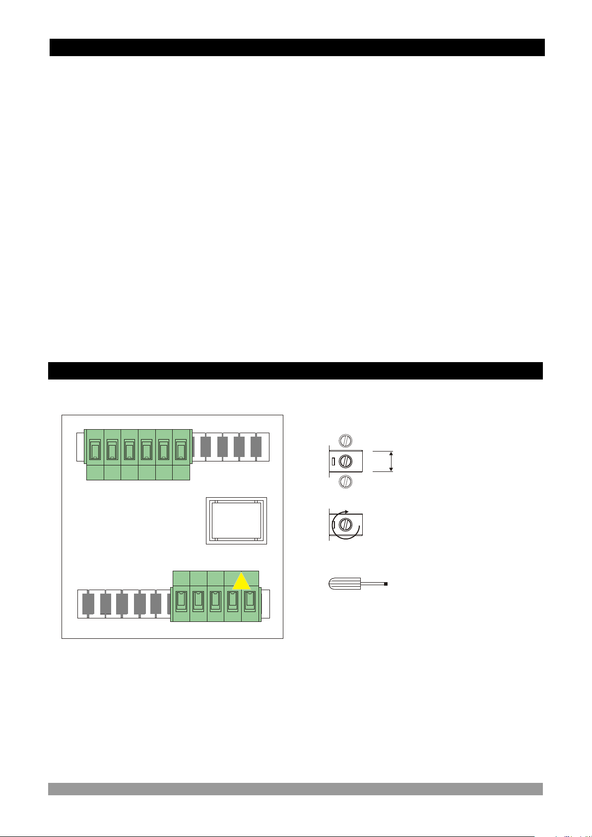
3.1 Terminal Layout and Connection Instructions
aa
Max. 2.5mm / 0.098 inch
Wire Size:
14AWG/1mm²
Solid / Stranded
Torque
0,5Nm
Screw driver
0,8 x3mm
12
Page 13
3.2 Electrical Wiring Diagram
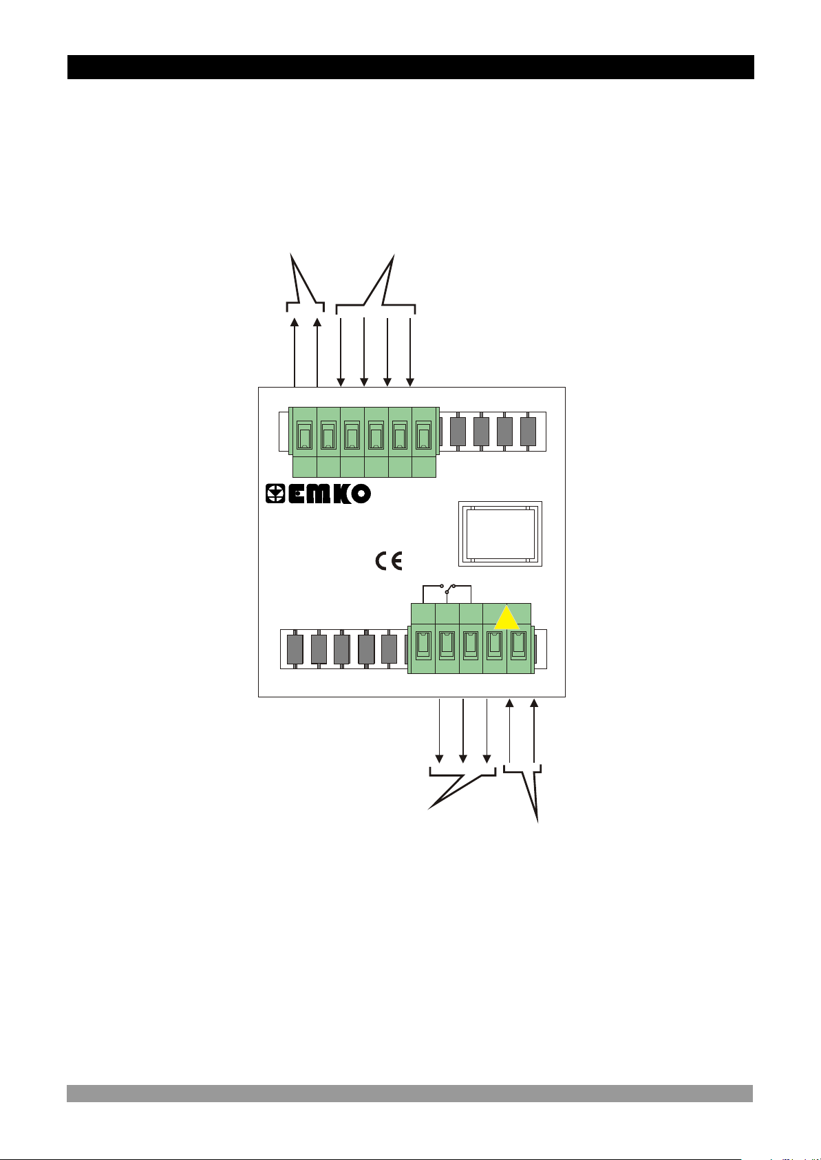
Electrical wiring of the device must be the same as ‘Electrical Wiring Diagram’
below to prevent damage to the process being controlled and personnel injury.
c
Sensor
Supply Voltage
Count Inputs
12 V Z
NOTE-1
Max 50mA
1
0 V Z
2 3
Ch A
Ch B
4
P/N : EZM-7730
Yc
PAUSE
5
18
RESET
6
5A@250VV
NO
C NC
19
20
21
aa
22
Relay Output
Supply Voltage Input
230V V (-%15;+%10) 50/60Hz - 2.3VA
115V V (-%15;+%10) 50/60Hz - 2.3VA
24 V V (-%15;+%10) 50/60Hz - 2.3VA
24 V Z (-%15 / +%10) - 4W
(It must be determined in order)
NOTE-1 : Sensor supply voltage: 12VZ ± 40%, 50 mA maximum with short circuit
protection
13
Page 14
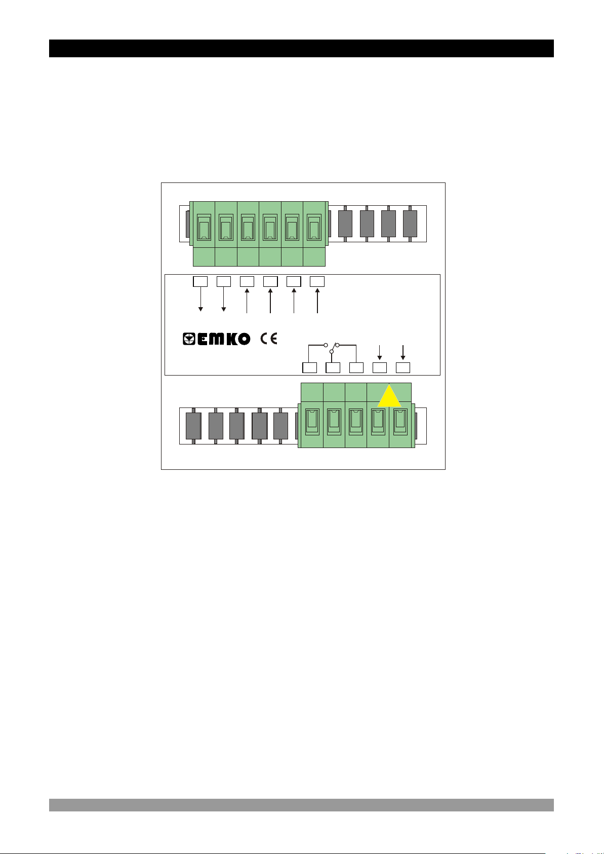
3.3 View of Device Label
P/N : EZM-7730
1 2 3 4 5 6
12 V Z
0 V Z
Ch-A
Max.50mA
Pause
Ch-B
NO
18 19 20 21
c
Reset
5A@250VV
NCC
a
Y
230V V -%15;+%10
50/60Hz -2.3VA
L
N
22
aa
14
Page 15
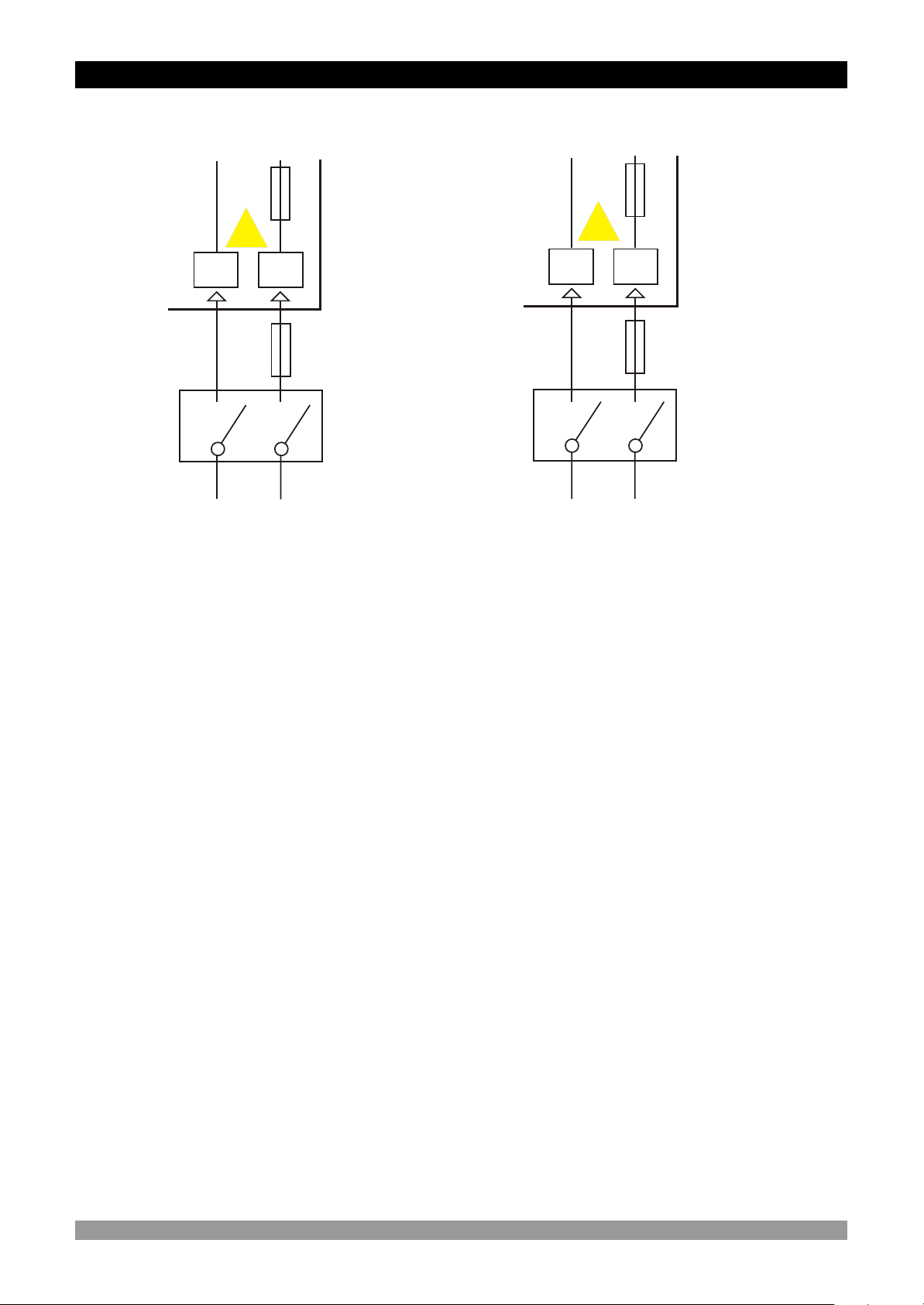
3.4 Connection of Device Supply Voltage Input
Connection of Universal
Supply Voltage Input
Y
Fuse
Note-1
N L
a
21
22
Note-3
External
Fuse
(1 A V T)
Power
Supply
Switch
c
Supply Voltage
115VV, 230 V V
(-%15;+%10) 50/60 Hz
Connection of Universal
Supply Voltage Input
Y
Fuse
Note-1
a
N
21
22
Note-3
L
Note-2
External
Fuse
(1 A V T)
Power
Supply
Switch
c
Supply Voltage
24V V (-%15;+%10) 50/60Hz
Note-1 :
There is internal 33 R W fusible 115V V 50/60 Hz and 230VV 50/60 Hz
There is internal 4R7 W fusible 24V V 50/60Hz
Note-2 : “L” is “+”, “N” is “-” for 24VZ supply voltage.
Note-3 : External fuse is recommended.
Make sure that the power supply voltage is the same indicated on the
instrument.
c
c
Switch on the power supply only after that all the electrical connections have
been completed.
Supply voltage range must be determined in order. While installing the unit,
supply voltage range must be controlled and appropriate supply voltage must
be applied to the unit. Controlling prevents damages in unit and system and
possible accidents as a result of incorrect supply voltage.
There is no power supply switch on the device. So a power supply switch must
be added to the supply voltage input. In accordance with the safety regulations,
the power supply switch shall bring the identification of the relevant
instrument.Power supply switch shall be easily accessible by the user.
Power switch must be two poled for seperating phase and neutral. On/Off
condition of power switch is very important in electrical connection. On/Off
condition of power switch must be signed for preventing the wrong connection.
flameproof resistor in
flameproof resistor in
If an external fuse is used, it must be on phase connection in Vsupply input.
15
Page 16
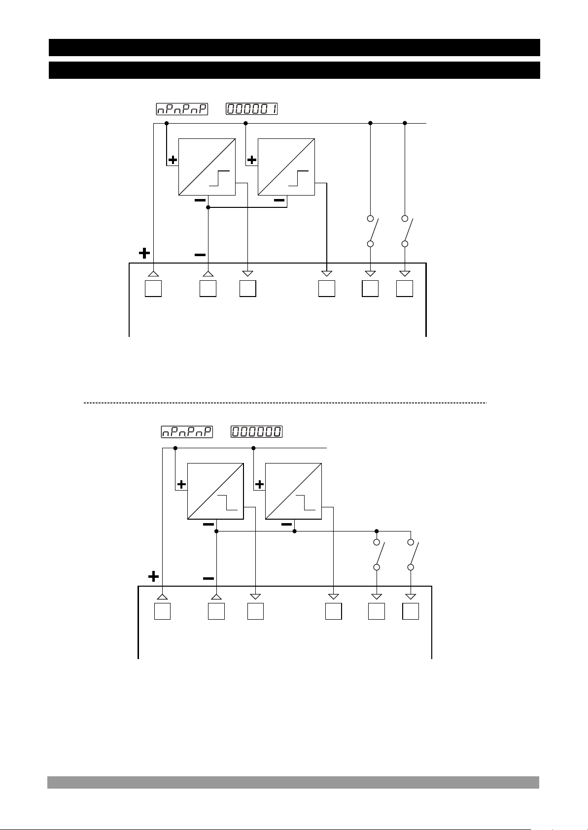
3.5 Counting Input Connection
3.5.1 Proximity & Switch Connection
=
PROX. PROX.
PNP type operation
PNP PNP
Switch
1 42 53 6
Max. 50mA
12 V Z
NOTE-1
0 V Z
ChA
ChB
Switch
PAUSE
RESET
=
PROX. PROX.
NPN type operation
NPN NPN
Switch
1 42 53 6
12 V Z
Max. 50mA
NOTE-1
0 V Z
ChA
ChB
Switch
PAUSE
RESET
NOTE-1 : Sensor supply voltage: 12VZ ± 40%, 50 mA maximum with short circuit
protection
16
Page 17
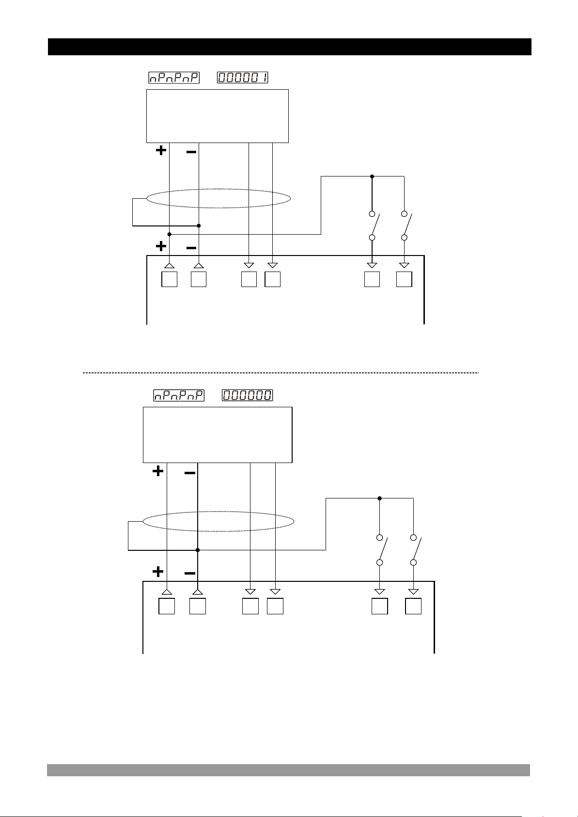
3.5.2 Incremental Encoder & Switch Connection
=
INCREMENTAL ENCODER
10 to 30V Z
1 42 53 6
0 V Z
12 V Z
Max. 50mA
NOTE-1
PNP type operation
ChA
ChB
Switch
Switch
PAUSE
RESET
=
INCREMENTAL ENCODER
10 to 30V Z
NPN type operation
Switch
1 42 53 6
ChA
ChB
12 V Z
Max. 50mA
NOTE-1
0 V Z
Switch
PAUSE
RESET
NOTE-1 : Sensor supply voltage: 12VZ ± 40%, 50 mA maximum with short circuit
protection
17
Page 18
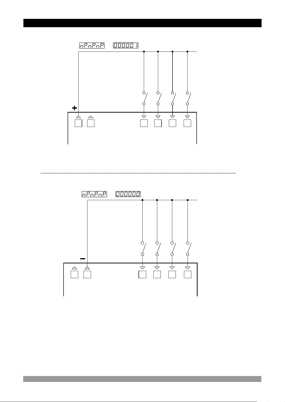
3.5.3 Switch Connection
=
1 42 53 6
0 V Z
12 V Z
Max. 50mA
NOTE-1
PNP type operation
Switch
Switch
ChA
ChB
Switch
Switch
PAUSE
RESET
=
1 42 53 6
0 V Z
12 V Z
Max. 50mA
NOTE-1
NPN type operation
Switch
Switch
ChA
ChB
Switch
Switch
PAUSE
RESET
NOTE-1 : Sensor supply voltage: 12VZ ± 40%, 50 mA maximum with short circuit
protection
18
Page 19
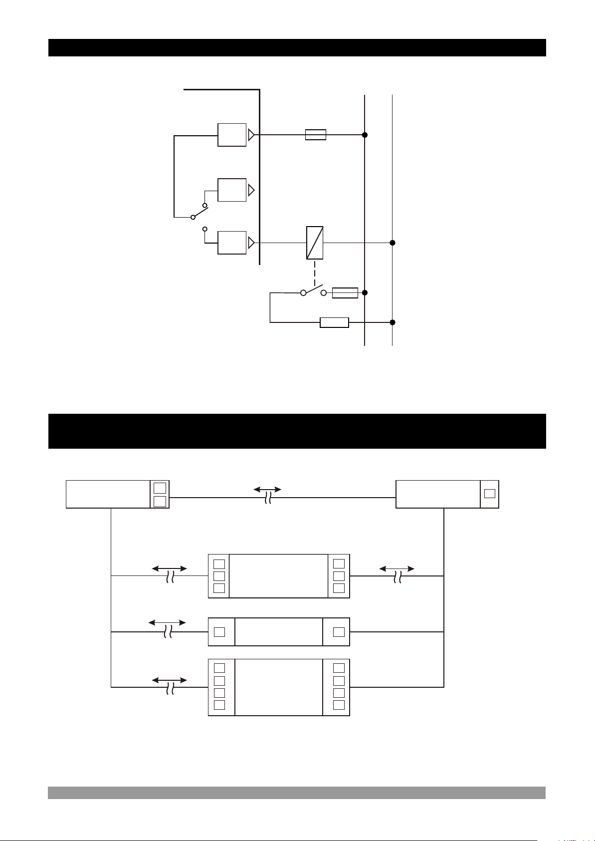
3.6 Relay Output Wiring Diagram
L N
c
C
5A V T Fuse
19
NC
NO
20
18
Last Control
Element
(Contactor)
c
Fuse
Load
Fuses must be selected according to the applications.
3.7 Galvanic Isolation Test Results of EZM-9930 Programmable Counter
3.7 Galvanic Isolation Test Results of EZM-7730 Programmable Counter
500V V ( for EZM-7730.3 )
2000V V ( for EZM-7730.5 )
Supply Voltage
21
22
2000V V
18
19
20
Relay Outout
18
19
20
0 V Z
2000V V
2000V V
2000V V
12V Z Sensor
Supply Voltage
4
5
Digital Inputs
11
33
4
5
66
2
19
Page 20
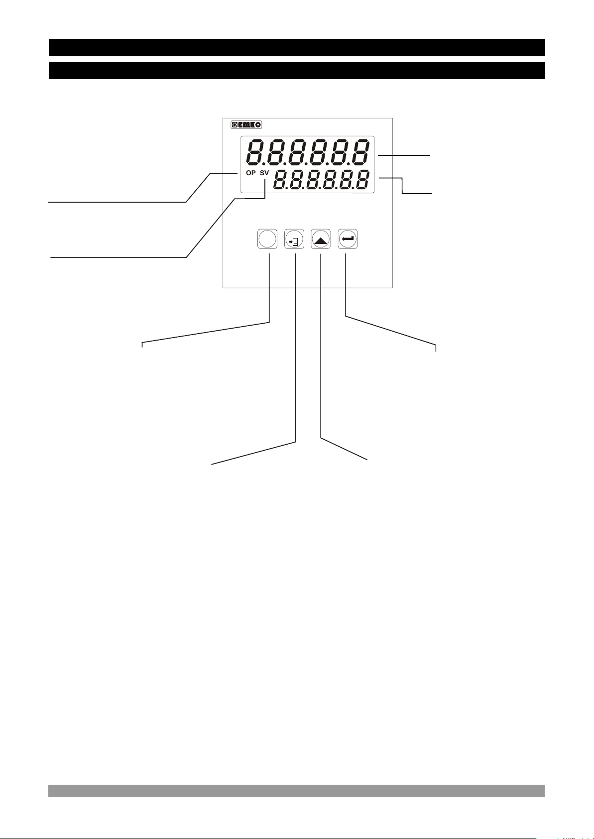
4.Definition of Front Panel and Accessing to the Set Parameters
4.1 Definition of Front Panel
EZM-7730
Led indication of output
OP
O2
SV
S2
is active
RESET
Led indication of SV:SET
SET
P
value
Counter
Displays Actual Value
and Name of Program
Parameter
Displays SET and
Parameter Value
PROG Button is
Used for accessing to the
Program Parameters
SHIFTING Button is used for
Changing the cursor position
in Programming mode and
entering the SET Value.
ENTER Button is used for
saving all changes to
memory and accessing to
the parameters.
RESET and INCREMENT
Button is used to Reset the
Actual Value or increment the
digit value that is selected by
SHIFTING Button.
20
Page 21
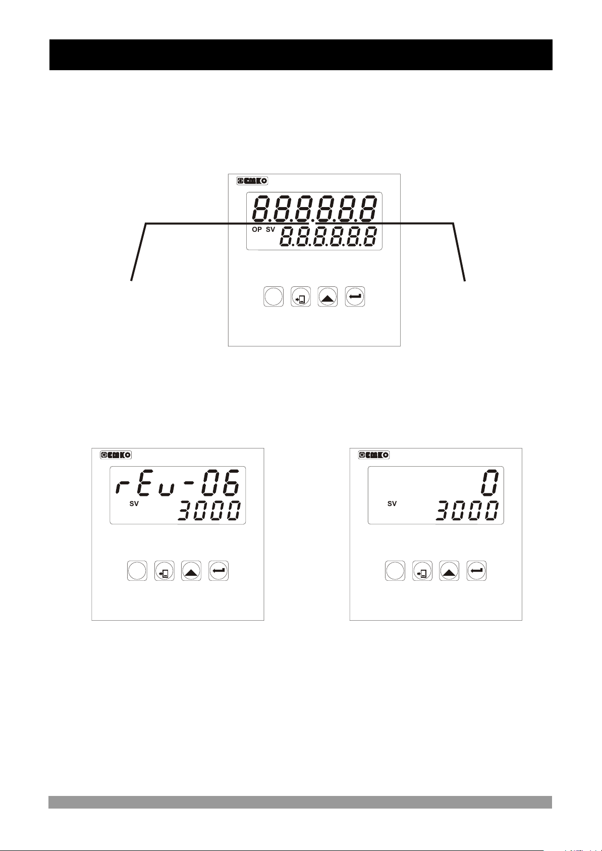
4.2 Power On Observation of EZM - 7730 Programmable Counter and Software
Revision on the Display
When power is applied to the device, software revision number of the controller is
illuminated
on actual value display. Then operation screen is observed.
When power on, view of the screen is shown below:
EZM-7730
SV
OP
S2
O2
“ rEu” Þ Revision
RESET
SET
P
Counter
Revision number
momentarily
OP
O2
SV
S2
EZM-7730
SV
OP
S2
O2
P
Counter
P
RESET
SET
RESET
SET
Counter
EZM-7730
Main screen is shown.Software Revision
c
If there is an unexpected situation while opening the device, power off the
device and inform a qualified personnel.
21
Page 22
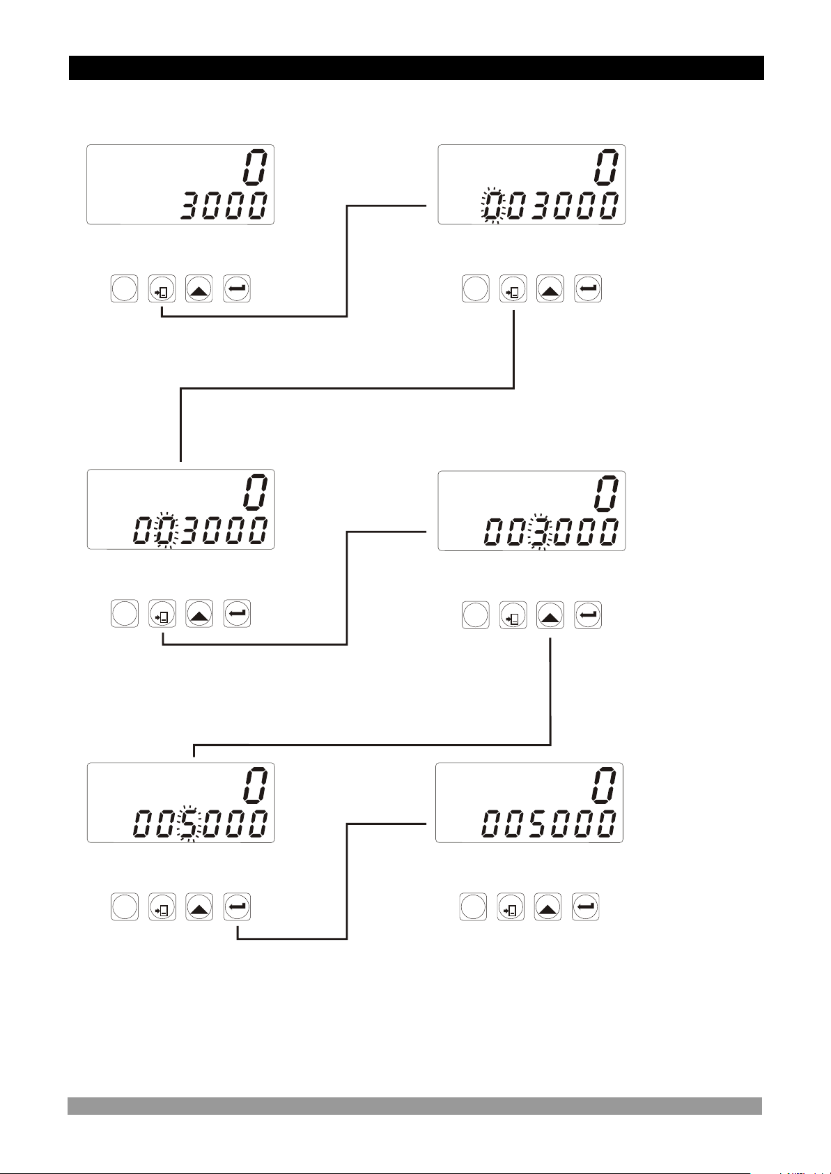
4.3 Adjustment of SET Value
Changing SET Value
Operation
Screen
SV
SV
OP
OP
S2
S2
O2
O2
RESET
SET
P
When shift button is pressed, 6th
digit of SET value starts to flash.
SET Screen SET Screen
SV
SV
OP
OP
S2
S2
O2
O2
RESET
SET
P
OP
OP
O2
O2
OP
OP
O2
O2
SV
SV
S2
S2
SV
SV
S2
S2
SET Screen
RESET
SET
P
Press Shift button again.
4th digit of
SET value
starts to
RESET
SET
P
flash.
5th digit of SET value starts
to flash.
SV
SV
OP
OP
S2
S2
O2
O2
RESET
SET
P
Save the value as SET value by
pressing Enter button.
Press Shift button again.
Increase the flashing
value with increment
button.
SET Screen Operation
Screen
SV
SV
OP
OP
S2
S2
O2
O2
RESET
SET
P
22
Page 23
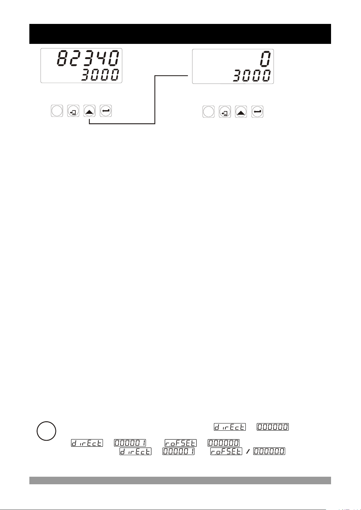
4.4 Resetting the Count Value
Operation
Screen
SV
SV
OP
OP
S2
S2
O2
O2
RESET
SET
P
When RESET button is pressed, Actual Value
becomes the Reset-Offset Value.
OP
OP
O2
O2
SV
SV
S2
S2
Operation
Screen
RESET
SET
P
RESET operation can be realized by Reset button or applying signal to the
RESET input. These two operations are named MANUAL RESET in parameters
section.
At the end of MANUEL RESET operation, if then Count
i
Value becomes Reset Offset Value.
If and then Count Value becomes
SET value. If and then count
value becomes Reset Offset Value.
=
=
=
=
=
23
Page 24
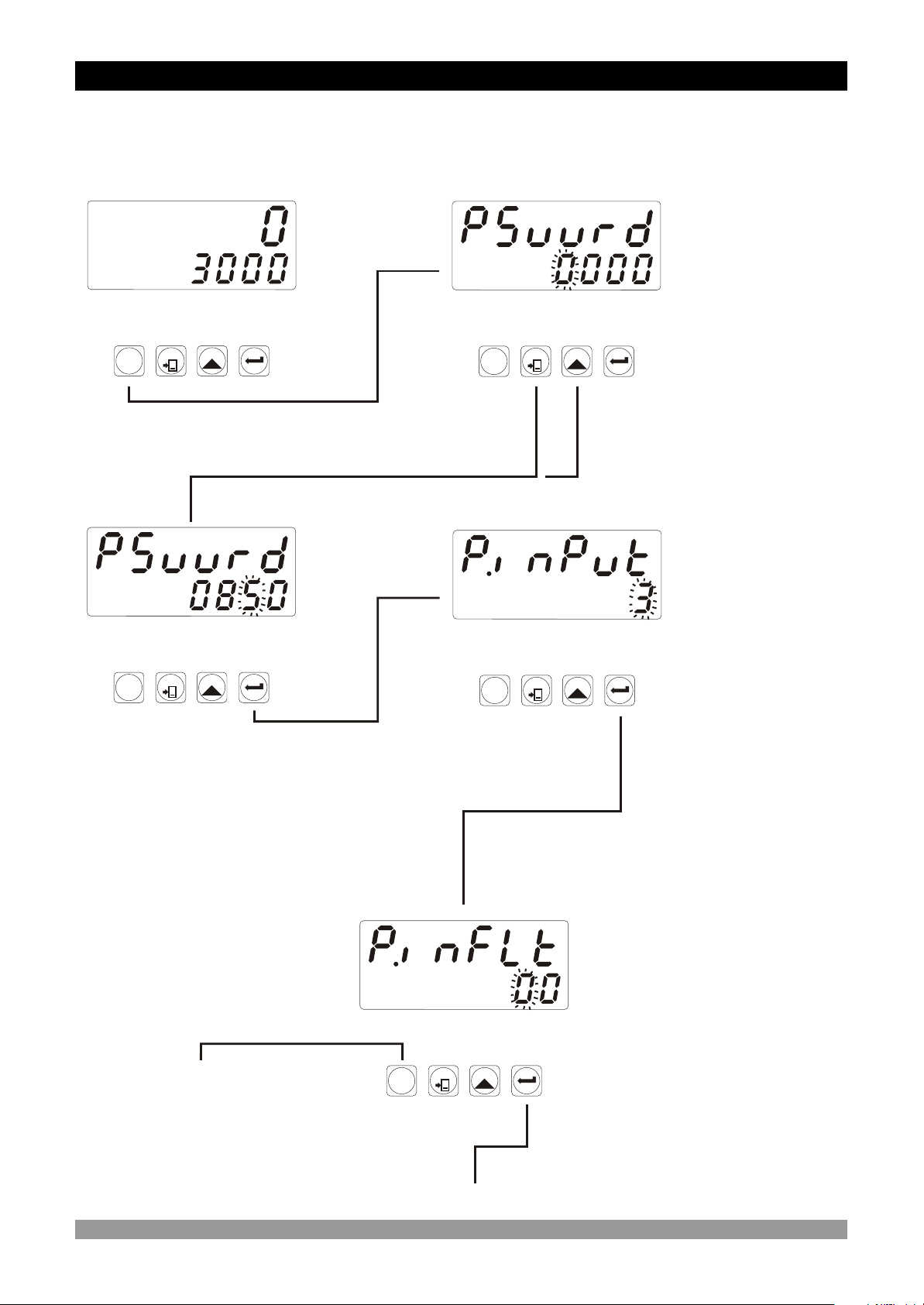
4.5 Accessing to the Program Parameters
In this section Accessing to the Program parameters process is shown.
For details on parameters refer to PROGRAM PARAMETERS section.
Operation
Screen
SV
SV
OP
OP
O2
O2
S2
S2
RESET
SET
P
OP
OP
O2
O2
When PROG button is pressed, password must
be entered to access the program parameters
Password
Screen
SV
SV
OP
OP
O2
O2
S2
S2
RESET
SET
P
OP
OP
O2
O2
SV
SV
S2
S2
SV
SV
S2
S2
Password Screen
The most
significant digit
of the parameter
(4th digit for this
parameter)
RESET
SET
P
flashes.
Enter password
with shift and
increment button
Input types and
functions
The most
significant digit
of the parameter
(1st digit for this
RESET
SET
P
parameter)
flashes.
Press Enter Button to
confirm password
The most significant digit of
the parameter (2nd digit for
this parameter) flashes.
Press PROG button to exit
from programming section
without doing any
changes.
OP
OP
O2
O2
SV
SV
S2
S2
Press Enter
Button
You can change the
parameter with
INCREMENT button,
save it to the memory and
pass to the next
parameter with ENTER
button.
Filter time for Ch-A and
Ch-B Input
You can change the
parameter with
INCREMENT button,
save it to the memory and
RESET
SET
P
pass to the next
parameter with ENTER
button.
Press Enter Button
24
Page 25
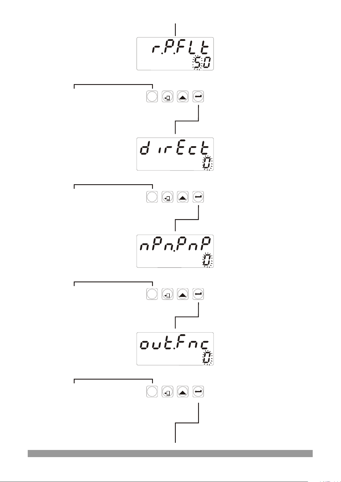
The most significant digit of
the parameter (2nd digit for
this parameter) flashes.
Press PROG button to exit
from programming section
without doing any
changes.
OP
OP
O2
O2
SV
SV
S2
S2
Filter time for Reset and
Pause Input
You can change the
parameter with
INCREMENT button,
save it to the memory and
RESET
SET
P
pass to the next
parameter with ENTER
button.
Press Enter Button
The most significant digit of
the parameter (1st digit for
this parameter) flashes.
Press PROG button to exit
from programming section
without doing any
changes.
The most significant digit of
the parameter (1st digit for
this parameter) flashes.
Press PROG button to exit
from programming section
without doing any
changes.
OP
OP
O2
O2
OP
OP
O2
O2
SV
SV
S2
S2
SV
SV
S2
S2
Direction of the counting
You can change the
parameter with
INCREMENT button,
save it to the memory and
RESET
SET
P
pass to the next
parameter with ENTER
button.
Press Enter Button
Sensor type selection
You can change the
parameter with
INCREMENT button,
save it to the memory and
RESET
SET
P
pass to the next
parameter with ENTER
button.
Press Enter Button
The most significant digit of
the parameter (1st digit for
this parameter) flashes.
Press PROG button to exit
from programming section
without doing any
changes.
OP
OP
O2
O2
SV
SV
S2
S2
Output Functions
You can change the
parameter with
INCREMENT button,
save it to the memory and
RESET
SET
P
pass to the next
parameter with ENTER
button.
Press Enter Button
25
Page 26
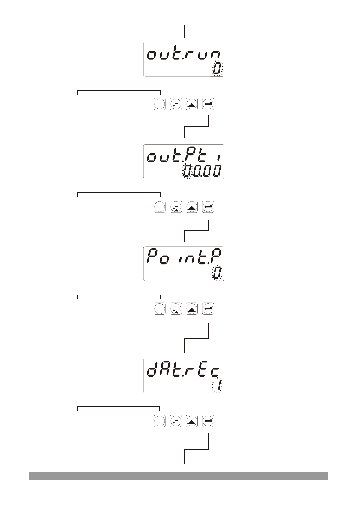
The most significant digit of
the parameter (1st digit for
this parameter) flashes.
Press PROG button to exit
from programming section
without doing any
changes.
OP
OP
O2
O2
SV
SV
S2
S2
Output Run Type
You can change the
parameter with
INCREMENT button,
save it to the memory and
RESET
SET
P
pass to the next
parameter with ENTER
button.
Press Enter Button
The most significant digit of
the parameter (4th digit for
this parameter) flashes.
Press PROG button to exit
from programming section
without doing any
changes.
The most significant digit of
the parameter (1st digit for
this parameter) flashes.
Press PROG button to exit
from programming section
without doing any
changes.
OP
OP
O2
O2
OP
OP
O2
O2
SV
SV
S2
S2
SV
SV
S2
S2
Output Pulse Time
You can change the
parameter with
INCREMENT button,
save it to the memory and
RESET
SET
P
pass to the next
parameter with ENTER
button.
Press Enter Button
Point Position
You can change the
parameter with
INCREMENT button,
save it to the memory and
RESET
SET
P
pass to the next
parameter with ENTER
button.
Press Enter Button
The most significant digit of
the parameter (1st digit for
this parameter) flashes.
Press PROG button to exit
from programming section
without doing any
changes.
OP
OP
O2
O2
SV
SV
S2
S2
Data Record
You can change the
parameter with
INCREMENT button,
save it to the memory and
RESET
SET
P
pass to the next
parameter with ENTER
button.
Press Enter Button
26
Page 27
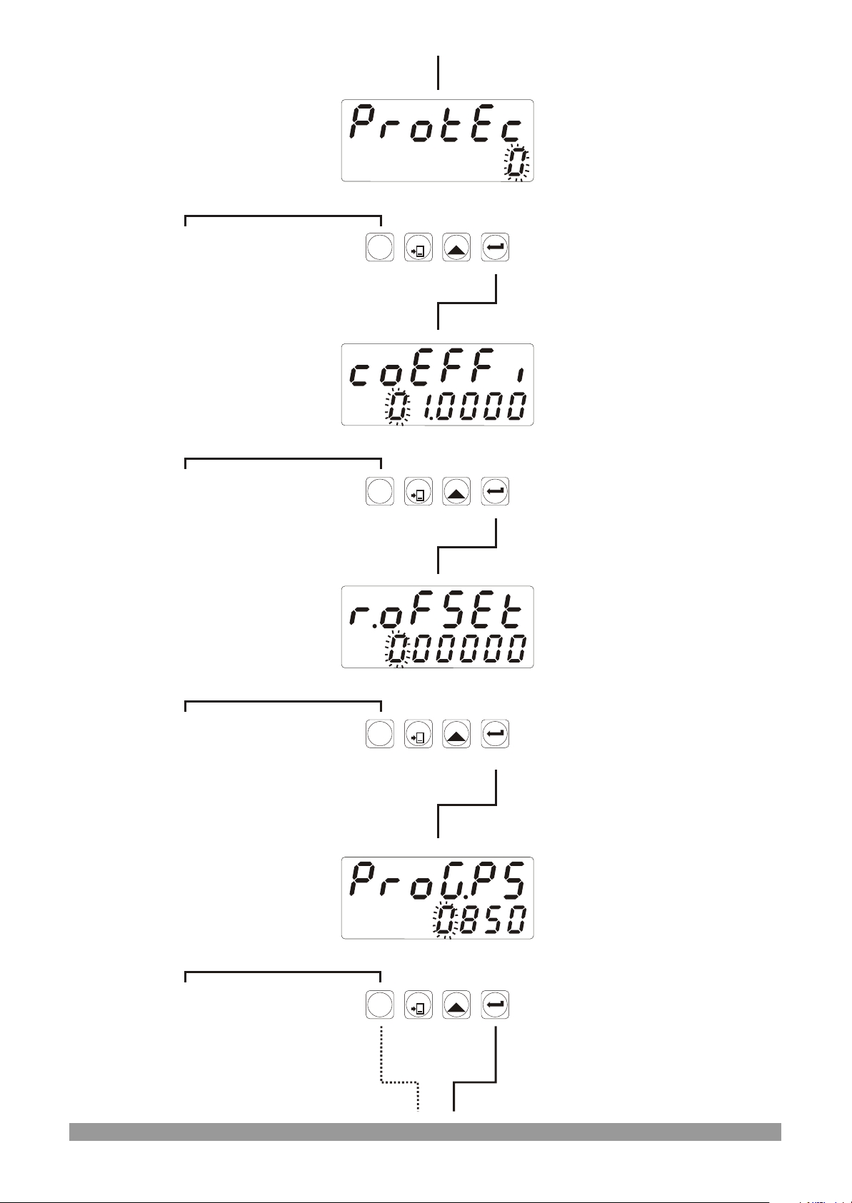
The most significant digit of
the parameter (1st digit for
this parameter) flashes.
Press PROG button to exit
from programming section
without doing any
changes.
OP
OP
O2
O2
SV
SV
S2
S2
Reset and Set Protection
You can change the
parameter with
INCREMENT button,
save it to the memory and
RESET
SET
P
pass to the next
parameter with ENTER
button.
Press Enter Button
The most significant digit of
the parameter (6th digit for
this parameter) flashes.
Press PROG button to exit
from programming section
without doing any
changes.
The most significant digit of
the parameter (6th digit for
this parameter) flashes.
Press PROG button to exit
from programming section
without doing any
changes.
OP
OP
O2
O2
OP
OP
O2
O2
SV
SV
S2
S2
SV
SV
S2
S2
Multiplication Coefficient
You can change the
parameter with
INCREMENT button,
save it to the memory and
RESET
SET
P
pass to the next
parameter with ENTER
button.
Press Enter Button
Reset Offset
You can change the
parameter with
INCREMENT button,
save it to the memory and
RESET
SET
P
pass to the next
parameter with ENTER
button.
Press Enter Button
The most significant digit of
the parameter (4th digit for
this parameter) flashes.
Press PROG button to exit
from programming section
without doing any
changes.
OP
OP
O2
O2
SV
SV
S2
S2
Program Password
You can change the
parameter with
INCREMENT button,
save it to the memory and
RESET
SET
P
pass to the next
parameter with ENTER
button.
Press Enter Button
27
Page 28
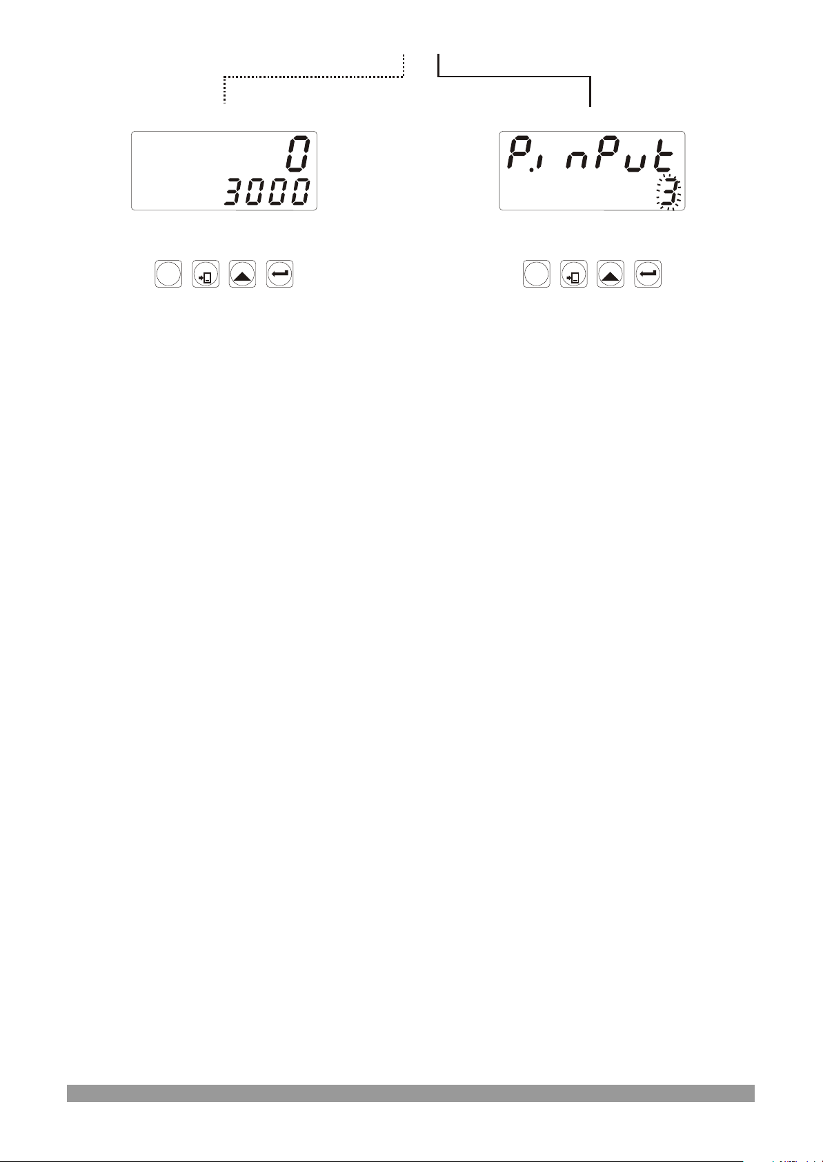
OP
OP
O2
O2
SV
SV
S2
S2
OP
OP
O2
O2
SV
SV
S2
S2
RESET
SET
P
Operation Screen
RESET
SET
P
Input types and functions
Continue to press ENTER
button for scanning all
parameters.
28
Page 29
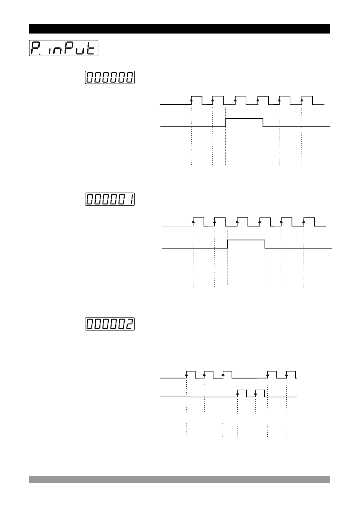
8. PARAMETRELER
5. Program Parameters
Input types and Functions
Upcount on rising edge of Ch-A input
Ch-A
Pause
Value on
the Screen
Downcount on rising edge of Ch-A input.
Ch-A
Pause
Value on
the Screen
Upcount on rising edge of Ch-A input.
Downcount on rising edge of Ch-B input.
Start
Value = 0
Start
Value = 8
1 2 3 4
7 6 5 4
Ch-A
Ch-B
Value on
the Screen
Value on
the Screen
Start
Value = 0
Start
Value = 8
1 2 2 2
7 6 6 65 7 5
3 1 3
Counting to
upwards
Counting to
downwards
29
Page 30
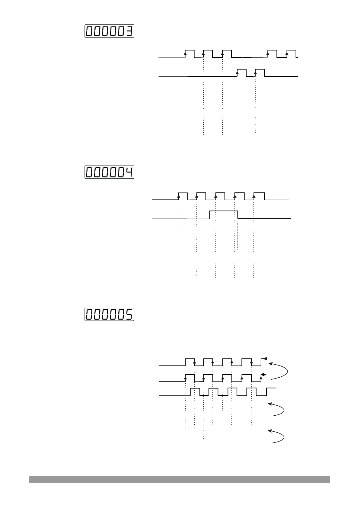
Upcount on rising edge of Ch-A input
Upcount on rising edge of Ch-B input
Ch-A
Ch-B
Value on
the Screen
Value on
the Screen
Value = 0
Start
Value = 8
1 2 4 6
7 6 4 25 3 1
3 5 7
Start
Upcount on rising edge of Ch-A input when Ch-B is at 0
Downcount on rising edge of Ch-A when Ch-B is at 1
Ch-A
Ch-B
Value on
the Screen
Value on
the Screen
Start
Value = 0
Start
Value = 8
UP UPDOWN
1 2 01 1
7 6 87 7
Counting to
upwards
Counting to
downwards
Counting to
upwards
Counting to
downwards
Encoder is travelling
in the Reverse Direction
Encoder is travelling
in the Forward Direction
Value on
the Screen
Value on
the Screen
x1 Phase Shifting (for incremental encoders)
Upcount on rising edge of Ch-A input when Ch-B is at 0
Downcount on rising edge of Ch-A input when Ch-B is at 1
Ch-A
Ch-A
Ch-B
Start
Value = 5
Start
Value = 8
6
6
7
7
7
7
6
6
8
8
5
5
9
9
10
4
4
3
Counting to
upwards
Counting to
downwards
30
Page 31
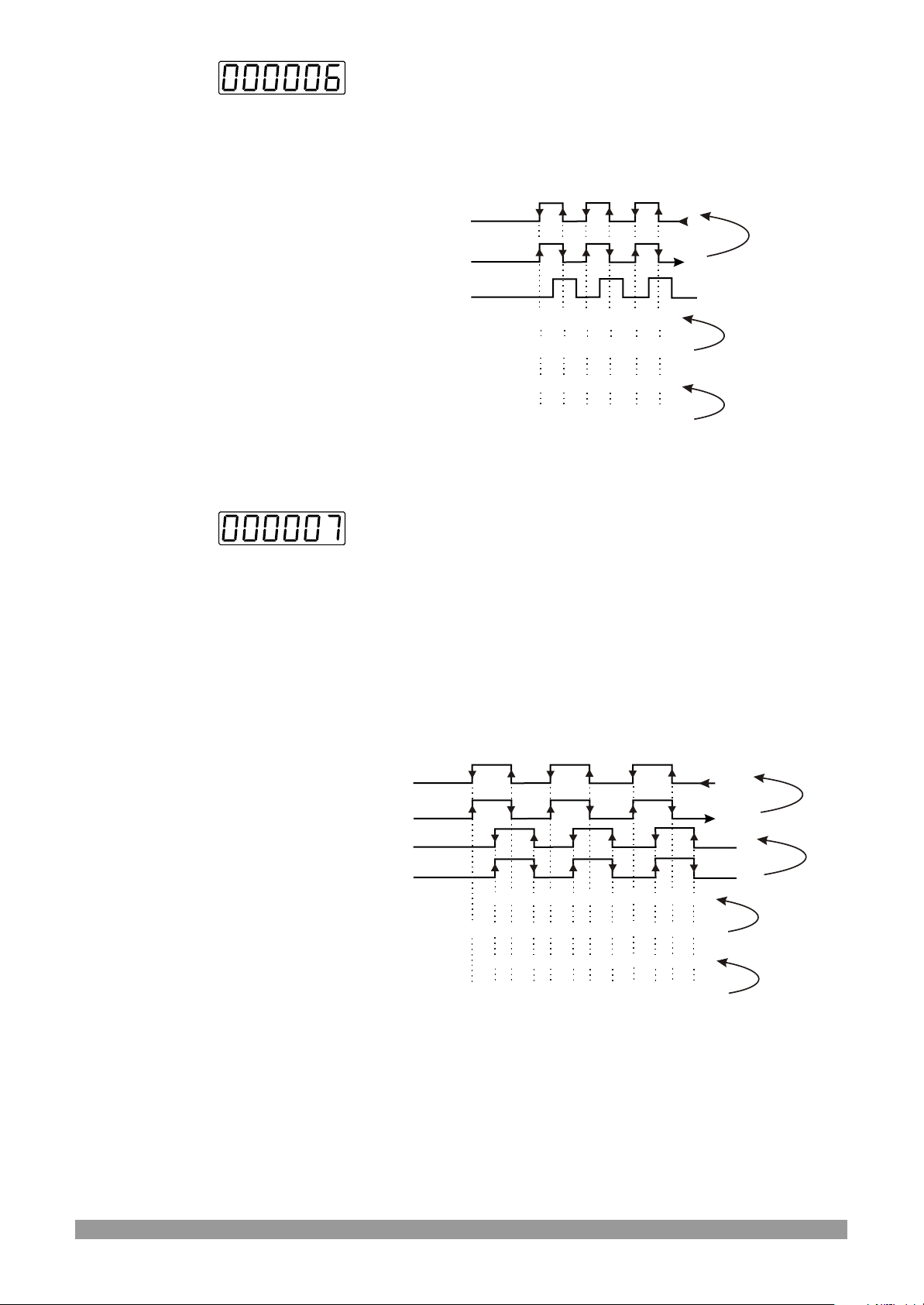
x2 Phase Shifting (for incremental encoders)
Upcount on rising edge of Ch-A when Ch-B is at 0
Downcount on rising edge of Ch-A when Ch-B is at 1
Upcount on falling edge of Ch-A when Ch-B is at 1
Downcount on falling edge of Ch-A when Ch-B is at 0
Encoder is travelling
in the Reverse Direction
Encoder is travelling
in the Forward Direction
Value on
the Screen
Value on
the Screen
x4 Phase Shifting (for incremental encoders)
Upcount on rising edge of Ch-A when Ch-B is at 0
Downcount on falling edge of Ch-A when Ch-B is at 0
Downcount on rising edge of Ch-A when Ch-B is at 1
Upcount on falling edge of Ch-A when Ch-B is at 1
Downcount on rising edge of Ch-B when Ch-A is at 0
Upcount on falling edge of Ch-B when Ch-A is at 0
Upcount on rising edge of Ch-B when Ch-A is at 1
Downcount on falling edge of Ch-B when Ch-A is at 1
Ch-A
Ch-A
Ch-B
Value = 14
Start
Value = 5
Start
14
13
5
6
13
12
7
6
7
8
11
1112
10
98
10
9
10
11
9
10
9 8
Counting to
upwards
Counting to
downwards
Encoder is travelling
in the Reverse Direction
Encoder is travelling
in the Forward Direction
Value
on the
Screen
Value
on the
Screen
Ch-A
Ch-A
Ch-B
Ch-B
Start
Value = 5
Start
Value = 17
16
13 141516
12
11
98
14
13
10
16
12
11
10
13
10
14
9
8
9
11
10
98
12
13
12
11
15
8
7
7
6 5
17
6
Counting to
upwards
Counting to
downwards
7
6
7
6
16
15
15
14
31
Page 32
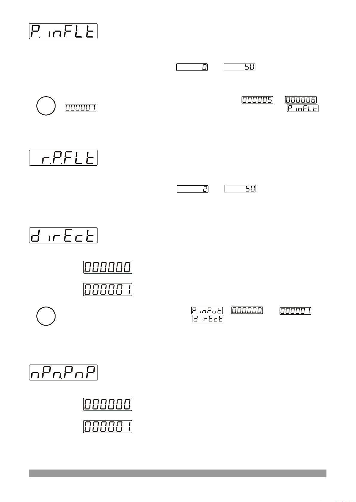
Filter time for Ch-A and Ch-B Inputs
It is used to protect against the electrical contact debounce or the signal
that is less than the determined pulse time.
It can be adjusted from to milisecond.
If Input types and Functions parameter; is entered , or
i
can not be accessed
then, pulse time for Ch-A and Ch-B Input parameter
Filter time for Reset and Pause Inputs
It is used to protect against the electrical contact debounce or the signal
that is less than the determined pulse time.
It can be adjusted from to milisecond.
Direction of Counting
Upcount. ( 0 --> Preset )
Downcount. ( Preset --> 0 )
Input types and Functions parameter is or
i
then Direction of Counting parameter can not be accessed.
Sensor Type Selection
NPN type sensor selected
PNP type sensor selected
32
Page 33
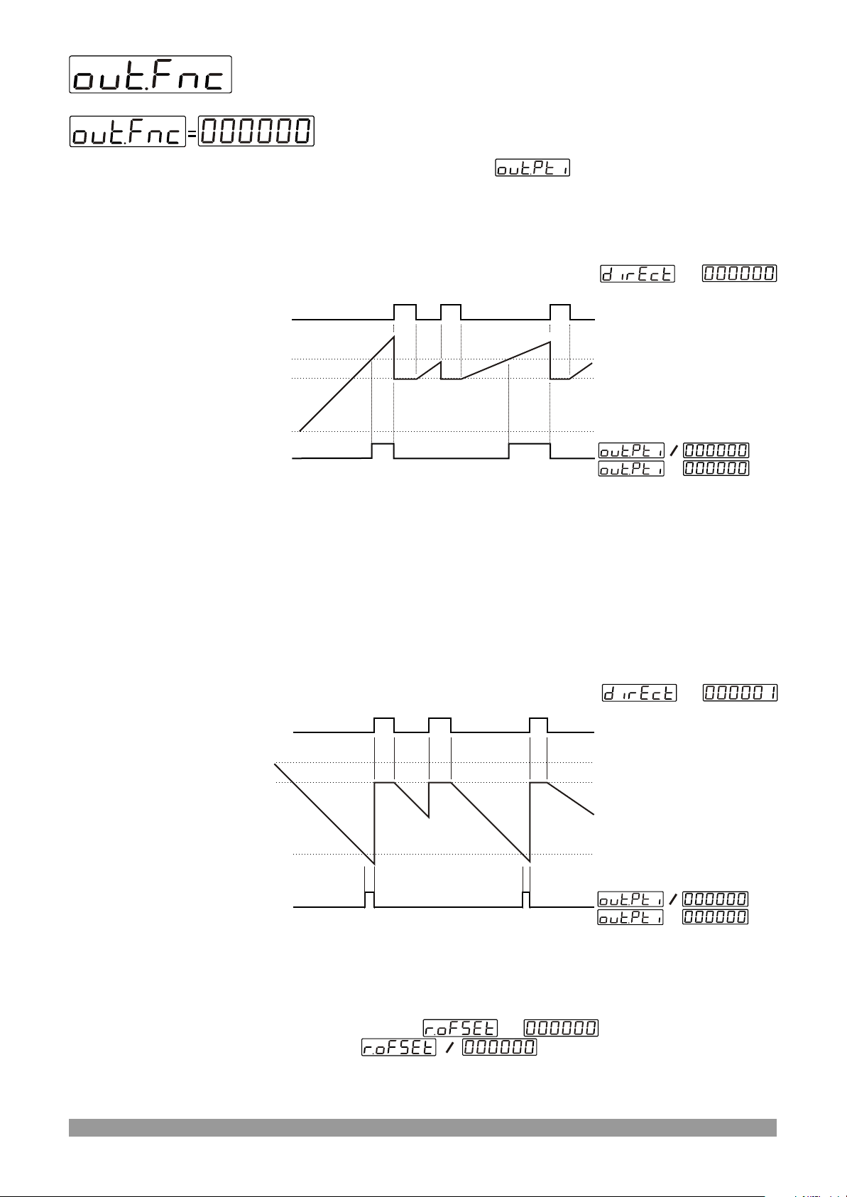
Output Functions
Manual Reset-1.
Device continues to count till manual reset is applied.
(Output PulseTime is not considered)
Count direction : 0 --> P (Upcounting)
Reset
Set
Reset Offset
0
Output
=
=
=
When count value reaches the Set Value, Output Position is changed.
Counting process continues over the SET value. Output Pulse Time is
not considered. Process counts, until manual reset happens. When
Manual Reset happens, count value becomes Reset Offset value.
Or
Counting direction : P --> 0 (Downcounting)
Reset
Set
Reset Offset
Output
When count value reaches the 0, Output Position is changed. Counting
process continues under the 0 value. Output Pulse Time is not
considered. Process counts, until manual reset happens. When Manual
Reset happens; if count value becomes
SET value, if then count value becomes
Reset Offset value.
=
0
=
=
=
=
Or
33
Page 34
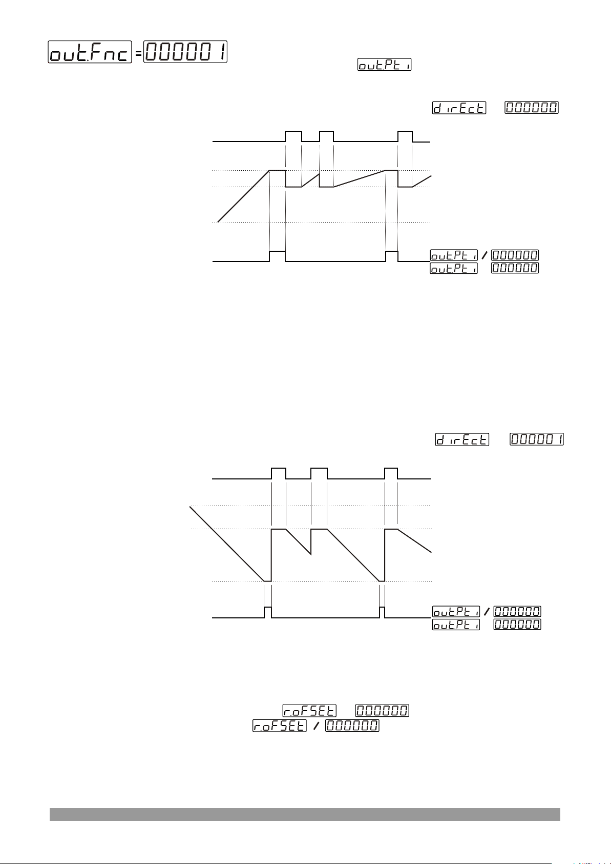
Manual Reset-2.
(Output pulse Time is not considered)
Counting direction : 0 --> P (Upcounting)
Reset
Set
Reset Offset
0
Output
=
=
=
When count value reaches the Set Value, Output Position is changed.
Counting process is not continue over the SET value. Output Pulse Time
is not considered. Process counts, until manual reset happens. When
Manual Reset happens, count value becomes Reset Offset value.
Or
Counting direction : P --> 0 (Downcounting)
Set
Reset Offset
Output
=
Reset
0
=
=
When count value reaches the 0, Output Position is changed. Counting
process is not continue under the 0 value. Output Pulse Time is not
considered. Process counts, until manual reset happens. When Manual
Reset happens; if , then count value becomes
SET value, if , then count value becomes Reset
=
=
Offset value.
Or
34
Page 35
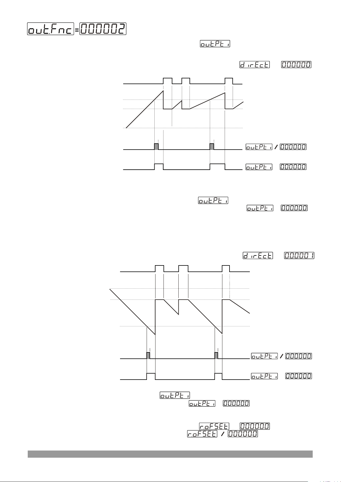
Manual Reset-3.
Device continues to count till manual reset is applied.
(Output Pulse Time is considered.)
Counting direction : 0 --> P (Upcounting)
Reset
Set
Reset Offset
0
Output
Output
=
=
=
When count value reaches the Set Value, Output Position is
changed. If Output Pulse time is not 0, then Output
Position is changed at the end of the Pulse time. If
=
then Output Position has not change until Manual Reset happens.
Counting process continues over the SET value.
When Manual Reset happens, count value becomes Reset Offset
value.
Counting direction : P --> 0 (Downcounting)
Reset
Set
Reset Offset
Output
Output
When count value reaches the 0 Value, Output Position is changed. If
Output Pulse time is not 0, then Output Position is changed
at the end of the Pulse time. If ,then Output Position
has not change until Manual Reset happens. Counting process
continues under the 0 value.
When Manual Reset happens; if , then count
value becomes SETvalue, if , then count value
becomes Reset Offset value.
=
0
=
=
=
=
=
35
Page 36
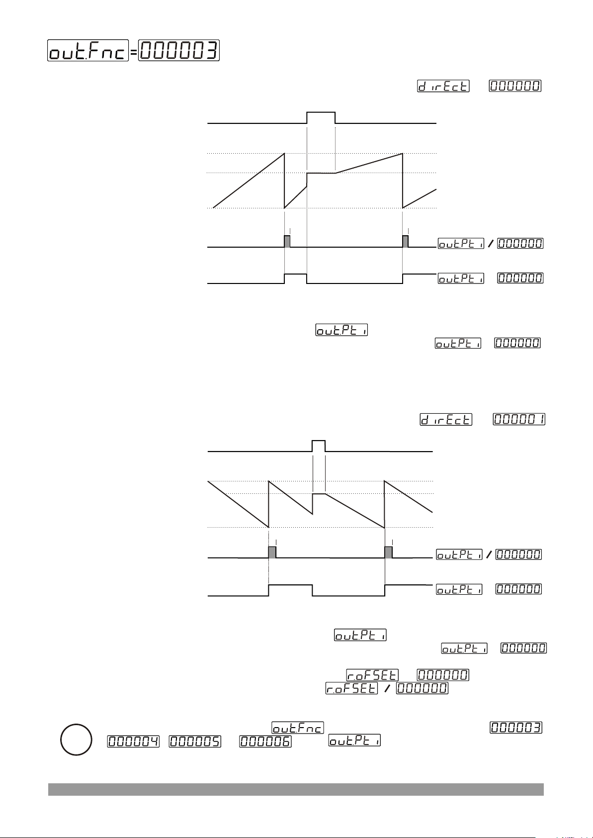
Automatic Reset-1
Counting direction : 0 --> P (Upcounting)
Reset
Set
Reset Offset
0
Output
Output
When count value reaches the Set Value, Output Position is changed.
Actual value is reset automatically. Counting starts upcounting from 0
value. If Output Pulse time is not 0, then Output Position is
changed at the end of the Pulse time. If Pulse time
then Output Position has not changed until Manuel Reset happens.
When Manual Reset happens, count value becomes Reset Offset
value.
=
=
=
=
Counting direction : P --> 0 (Downcounting)
Reset
Set
Reset Offset
0
Output
Output
When count value reaches the 0 Value, Output Position is changed.
Actual value is reset automatically. Counting starts downcounting from
Set value. If Output Pulse time is not 0, then Output Position
is changed at the end of the Pulse time. If Pulse time
then Output Position has not changed until Manuel Reset happens.
When Manual Reset happens; if , then count
value becomes SETvalue, if , then count value
becomes Reset Offset value.
=
=
=
=
=
=
If output functions parameter is selected Automatic Reset (
i
, or , then must be different from zero
for realizing Automatic Reset.
36
Page 37
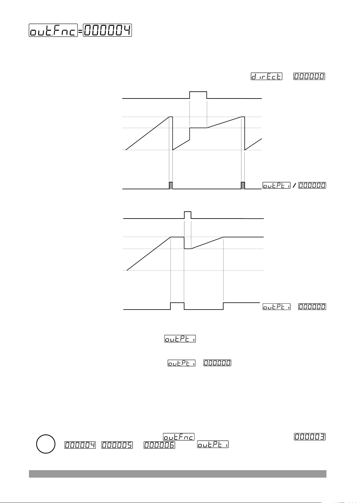
Automatic Reset-2
Counting direction : 0 --> P (Upcounting)
Reset
Set
Reset Offset
0
Output
Reset
Set
Reset Offset
=
=
0
Output
When count value reaches the Set Value, Output Position is changed. If
Output Pulse time is not 0, then Output Position is changed
the old position at the end of the Pulse time. Actual value is reset and
counting starts from 0 value at the end of the Output Pulse time.
If output pulse time then, output position has not
change until Manual Reset happens. Actual counting value stops at SET
value. Counting process is not continue over the SET value.
When Manual Reset happens, count value becomes Reset Offset
value.
If output functions parameter is selected Automatic Reset (
i
, or , then must be different from zero
for realizing Automatic Reset.
=
=
37
Page 38
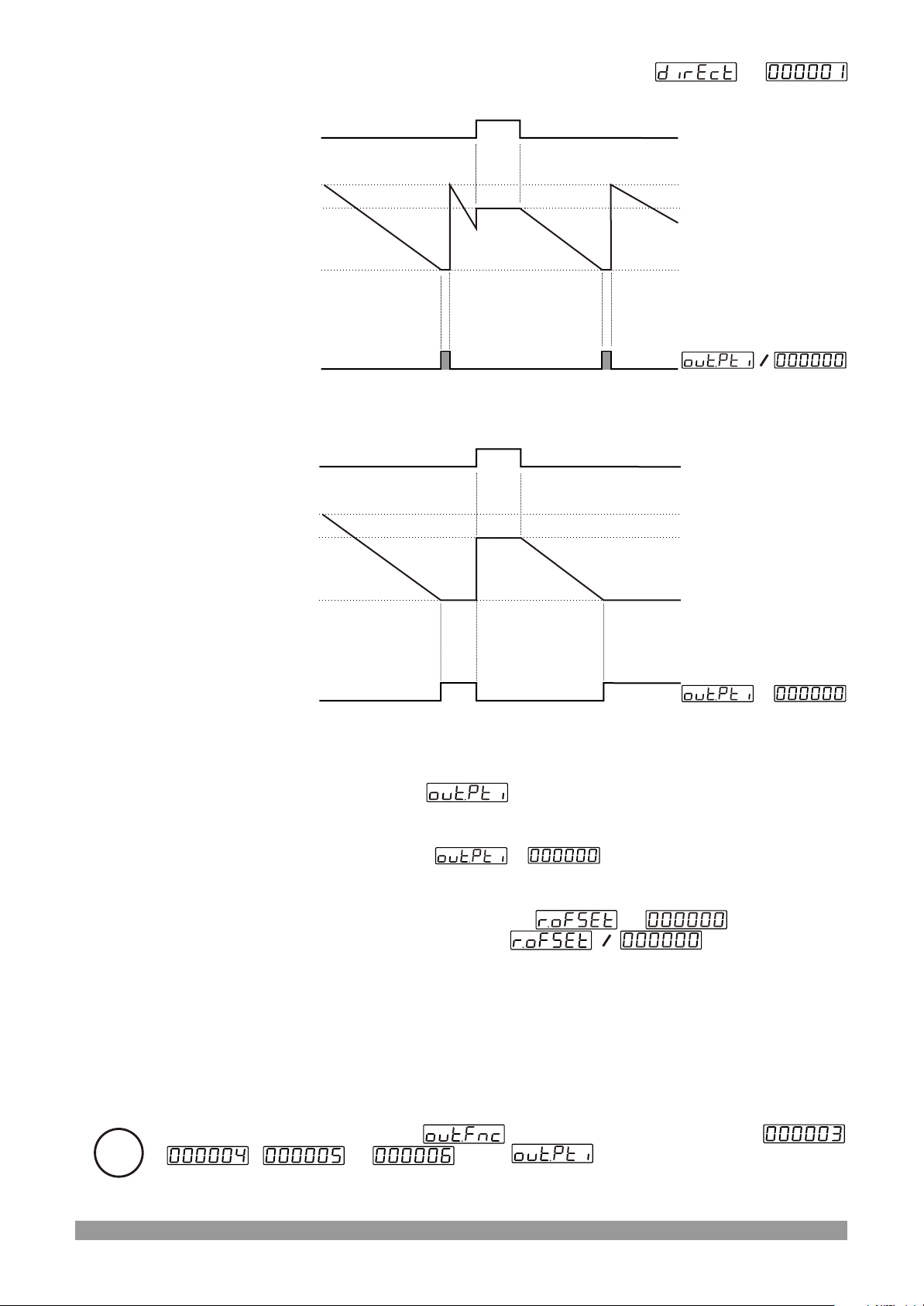
Counting direction : P --> 0 (Downcounting)
Reset
Set
Reset Offset
0
=
Output
Reset
Set
Reset Offset
0
Output
When count value reaches the 0 Value, Output Position is changed. If
Output Pulse time is not 0, then Output Position is changed
the old position at the end of the Pulse time. Actual value is reset and
counting starts from SET value at the end of the Output Pulse time.
If output pulse time , then output position has not
change until Manual Reset happens. Actual counting value stops at SET
value. Counting process is not continue under the 0 value.
When Manual Reset happens, if , then count
value becomes SET value. If , t h e n c o u n t
value becomes Reset Offset value.
=
=
=
=
=
If output functions parameter is selected Automatic Reset (
i
, or , then must be different from zero
for realizing Automatic Reset.
38
Page 39
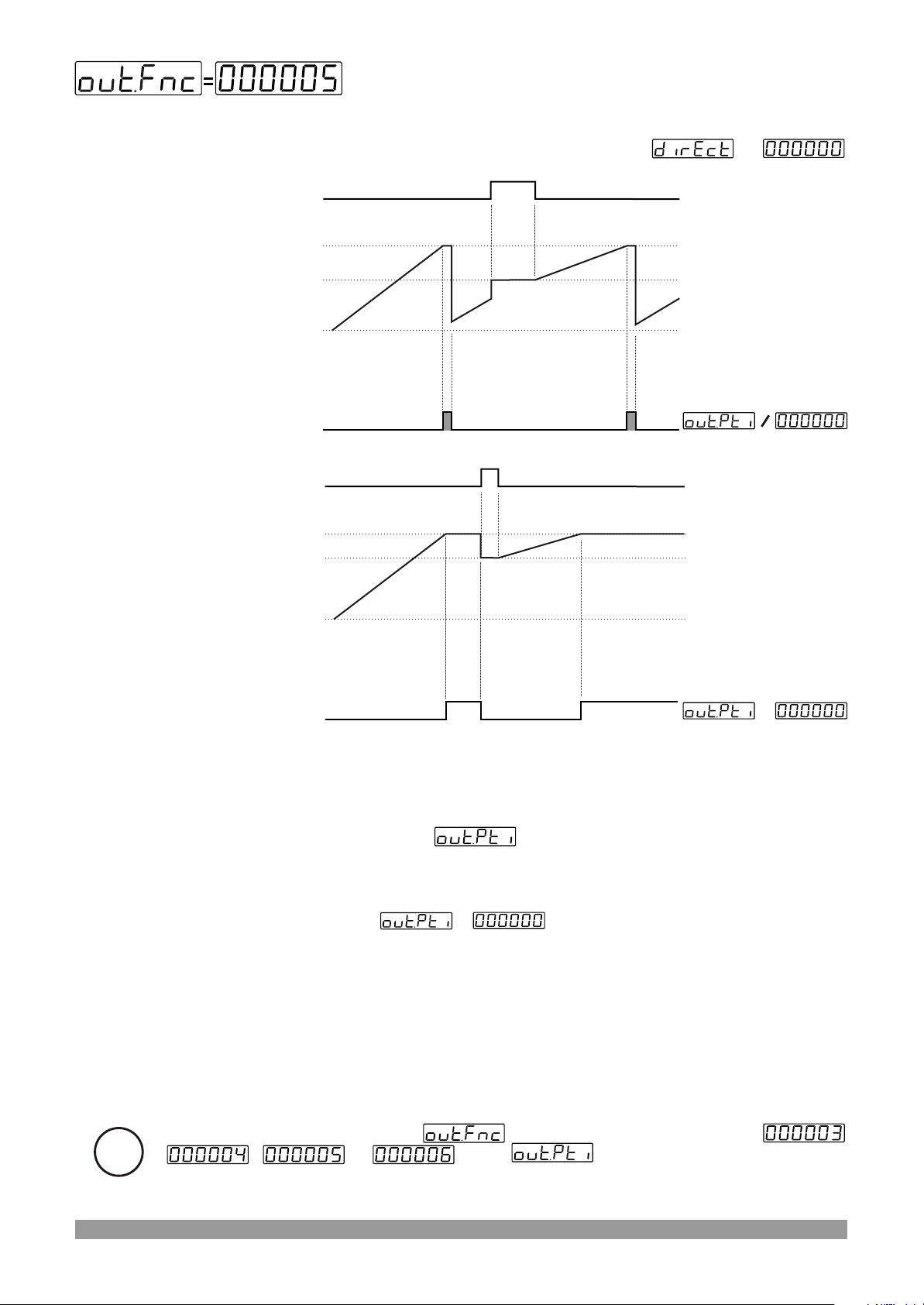
Automatic Reset-3
Counting direction : 0 --> P (Upcounting)
Reset
Set
Reset Offset
0
Output
Reset
Set
Reset Offset
=
=
0
Output
When count value reaches the SET Value, Output Position is changed.
If Output Pulse time is not 0, then Output Position is changed
the old position at the end of the Pulse time. Count value starts counting
from 0 value. But SET value is observed in actual value display. Real
counting value is shown on Actual value screen at the end of the Output
pulse time. If ,then output position has not changed
until Manual Reset happens. Counting process has not continue over
SET value.
When Manual Reset happens, count value becomes Reset Offset
value.
=
=
If output functions parameter is selected Automatic Reset (
i
, or , then must be different from zero
for realizing Automatic Reset.
39
Page 40
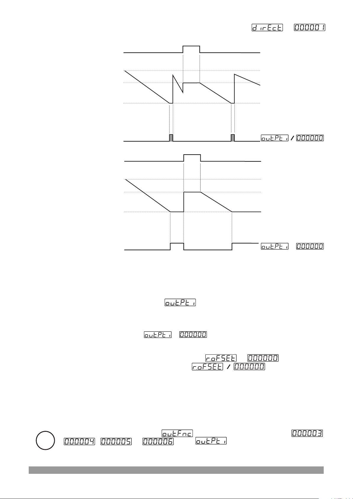
Counting direction : P --> 0 (Downcounting)
Reset
Set
Reset Offset
=
0
Output
Reset
Set
Reset Offset
0
Output
When count value reaches the 0 Value, Output Position is changed. If
Output Pulse time is not 0, then Output Position is changed
the old position at the end of the Pulse time. Count value starts counting
from SET value. But 0 value is observed in actual value display. Real
counting value is shown on Actual value screen at the end of the Output
pulse time. If ,then output position has not changed
until Manual Reset happens. Counting process has not continue over 0
value.
When Manual Reset happens, if , then count
value becomes SET value. If ,then count value
becomes Reset Offset value.
=
=
=
=
=
If output functions parameter is selected Automatic Reset (
i
, or , then must be different from zero
for realizing Automatic Reset.
40
Page 41
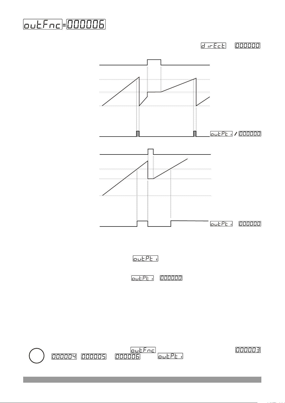
Automatic Reset-4
Counting direction : 0 --> P (Upcounting)
Reset
Set
Reset Offset
Output
Reset
Set
Reset Offset
=
0
=
0
Output
When count value reaches the SET Value, Output Position is changed.
If Output Pulse time is not 0, then Output Position is changed
at the end of the Pulse time. Counting continue over SET value.
Counting value becomes 0 and output position becomes old position. If
output pulse time ,then output position has not
change until Manual Reset happens.
When Manual Reset happens, count value becomes Reset Offset
value.
=
=
If output functions parameter is selected Automatic Reset (
i
, or , then must be different from zero
for realizing Automatic Reset.
41
Page 42
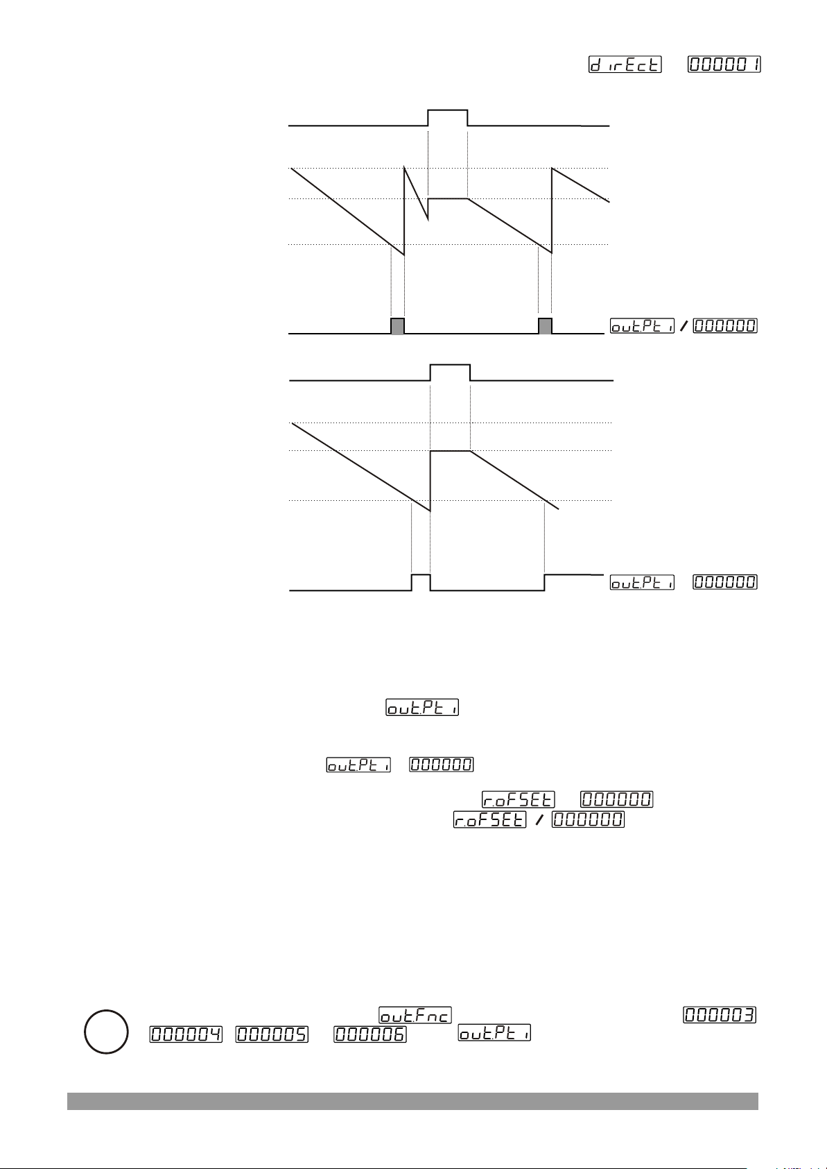
Counting direction : P --> 0 (Downcounting)
Reset
Set
Reset Offset
=
0
Output
Reset
Set
Reset Offset
0
Output
When count value reaches the 0 Value, Output Position is changed. If
Output Pulse time is not 0, then Output Position is changed
at the end of the Pulse time. Counting continue under 0 value. Counting
value becomes SET and output position becomes old position. If output
pulse time ,then output position has not change
until Manual Reset happens.
When Manual Reset happens, if , then count
value becomes SET value. If ,then count value
becomes Reset Offset value.
=
=
=
=
=
If output functions parameter is selected Automatic Reset (
i
, or , then must be different from zero
for realizing Automatic Reset.
42
Page 43
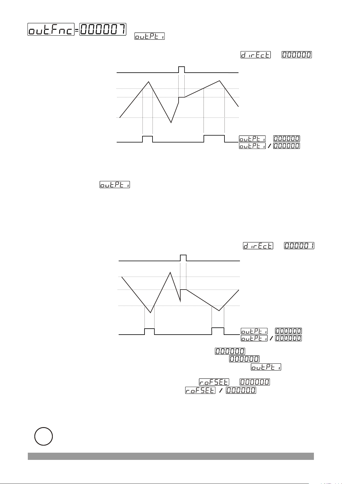
Automatic Reset-5
is not considered.
Counting direction : 0 --> P (Upcounting)
Reset
Set
Reset Offset
0
Output
=
=
=
If count value equal or greater than SET value, then output becomes
active. If count value less than SET value, then output becomes inactive.
is not considered. Counting process continues over the Set
value.
When Manual Reset happens, count value becomes Reset Offset
value.
Or
Counting direction : P --> 0 (Downcounting)
Reset
Set
Reset Offset
0
Output
=
=
=
If count value is equal or less than value, then output
becomes active. If count value greater than v a l u e , t h e n
output becomes inactive. Output Pulse time is not
considered.
When Manual Reset happens; if , then count
value becomes SETvalue, if , then count value
becomes Reset Offset value.
=
=
Or
i
It is preferred if upcount and downcount is performed at the same time.
43
Page 44
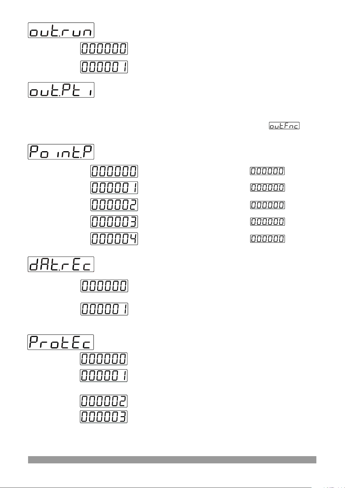
Output Run Type
Output Normally non-energised
Output Normally energised
Output Pulse Time
It determines how long Output will be active.
It can be adjusted from 00.00 to 99.99 seconds.
If it is 00.00 second, then it operates indefinitely.
For details, refer to the section where output functions are
defined
Point Position for Display
No point
Between first and second digits
Between second and third digits
Between third and fourth digits
Between fourth and fifth digits
Data Record
Count value is saved to memory when power is
disconnected and restored on power up.
Count value is not saved to memory when power is
disconnected. When power up, if the direction is upcounting,
0 value is shown on the screen. If the direction is down
counting then SET value is shown on the screen.
Reset and Set Protection (for Front Panel Access)
There is no Reset and Set protection
Only RESET Button protection is active.
Actual value can not be reset by Reset button.
SET value can not be changed.
Full protection ; Reset protection is active and SET value can
not be changed.
44
Page 45
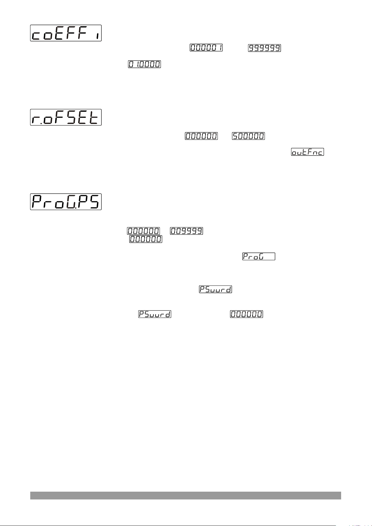
Multiplication Coefficient
It can be adjusted from to . Changes in this
parameter is evaluated when counting starts.
If it is multiplication is not performed. So number of pulses are
displayed without having any changes.
Reset Offset
It can be adjusted from to .
For details, refer to the section where output functions are
defined
Program Password
It is used for accessing to the program parameters. It can be adjusted
from to .
If it is , there is no password protection while accessing to the
parameters.
When programming button is pressed, will appear on the
display.
If program password is not “0” while accessing to the program
parameters ;
1- If user does not enter the value correctly ; operation screen
will appear without entering to operator parameters.
2- When in top display and in bottom display,if user
presses ENTER button without entering password (for observing the
parameters):
User can see all parameters except Program Password but device does
not allow to do any changes with parameters.
45
Page 46
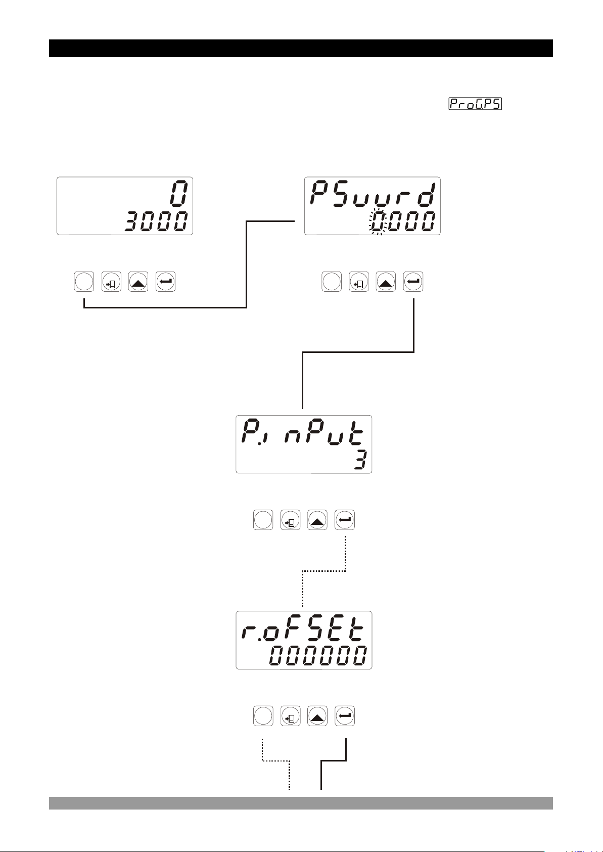
6. Failure Messages in EZM-7730 Programmable Counter
1-If the password is not 0, user can access to the parameters without entering the password
and by pressing ENTER button.
User can see all parameters except for programming password parameter but user
can not do any changes in parameters. If password is entered for accessing to the parameters
correctly, most significant digit of the parameter flashes. But if the password is not entered,
flashing of the most significant digit is not realised.
Operation
Screen
SV
SV
OP
OP
S2
S2
O2
O2
RESET
SET
P
When PROG button is pressed,
password entering screen will
appear.
OP
OP
O2
O2
SV
SV
S2
S2
OP
OP
O2
O2
SV
SV
S2
S2
Password Screen
The most
significant digit
of the parameter
(4th digit for this
RESET
SET
P
parameter)
flashes.
Press ENTER
button without
entering the
password.
Input Types
and Functions
No digit flashes
Press PROG button to exit
from programming mode.
OP
OP
O2
O2
SV
SV
S2
S2
RESET
SET
P
By pressing ENTER
button, user can see all
parameters except for
program password
Reset Offset Parameter
RESET
SET
P
Continue to press ENTER
button for scanning the
parameters.
46
Page 47
OP
OP
O2
O2
SV
SV
S2
S2
OP
OP
O2
O2
SV
SV
S2
S2
OP
OP
O2
O2
OP
OP
O2
O2
SV
SV
S2
S2
SV
SV
S2
S2
RESET
SET
P
Operation Screen
P
Input Types and Functions
RESET
SET
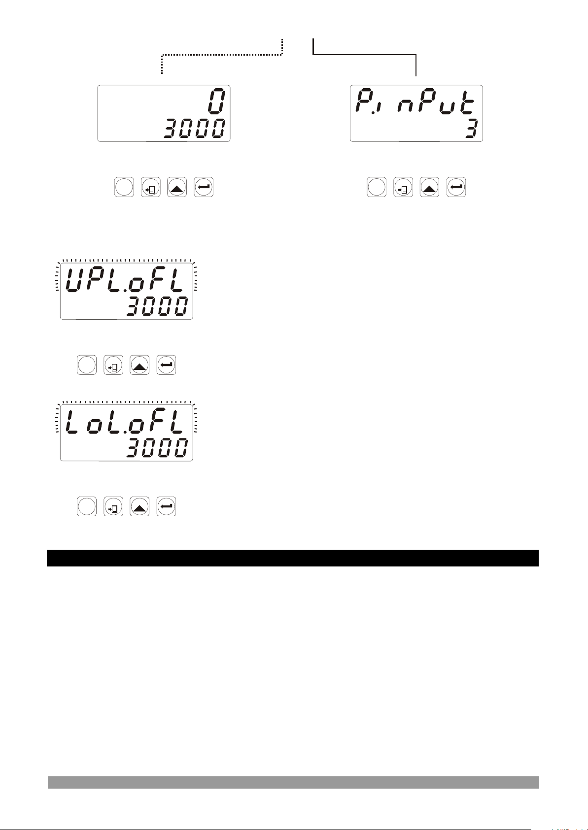
2-If Actual Value is flashing and counting is stopped ;
It appears if any of the count value is greater than the
maximum count value.
To remove this warning and reset the count value press
RESET button.
RESET
SET
P
3-If Actual Value is flashing and counting is stopped ;
It appears if any of the count value is lower than the
minimum count value.
To remove this warning and reset the count value press
RESET button.
RESET
SET
P
7. Specifications
Device Type : Programmable Counter
Housing & Mounting : 72mm x 72mm x 87.5 DIN Size 43700 plastic housing for
panel mounting. Panel cut-out is 69x69mm
Protection Class : IP65 at front, IP20 at rear.
Weight : Approximately 0.25 Kg.
Environmental Ratings : Standard, indoor at an altitude of less than 2000 meters
with none condensing humidity
Storage / Operating Temperature: -40 C to +85 C / 0 C to +50 C
oooo
Storage / Operating Humidity : 90 % max. (None condensing)
Installation : Fixed installation
Over Voltage Category : II
Pollution Degree : II, office or workplace, none conductive pollution
Operating Conditions : Continuous
47
Page 48
Supply Voltage and Power : 230 V V (-%15 / +%10) 50/60 Hz. 2.3VA
115 V V (-%15 / +%10) 50/60 Hz. 2.3VA
24 V V (-%15 / +%10) 50/60 Hz. 2.3VA
24 V Z (-%15 / +%10) - 4W
Digital Inputs
Electrical Characteristics : Rated voltage : 16 VZ @ 5mA
Maximum continuous permissible voltage : 30 VZ
Logic 1 minimum level : 3 VZ
Logic 0 maximum level : 2 VZ
Sensor Supply Voltage : 12VZ ± %40 max. 50mA
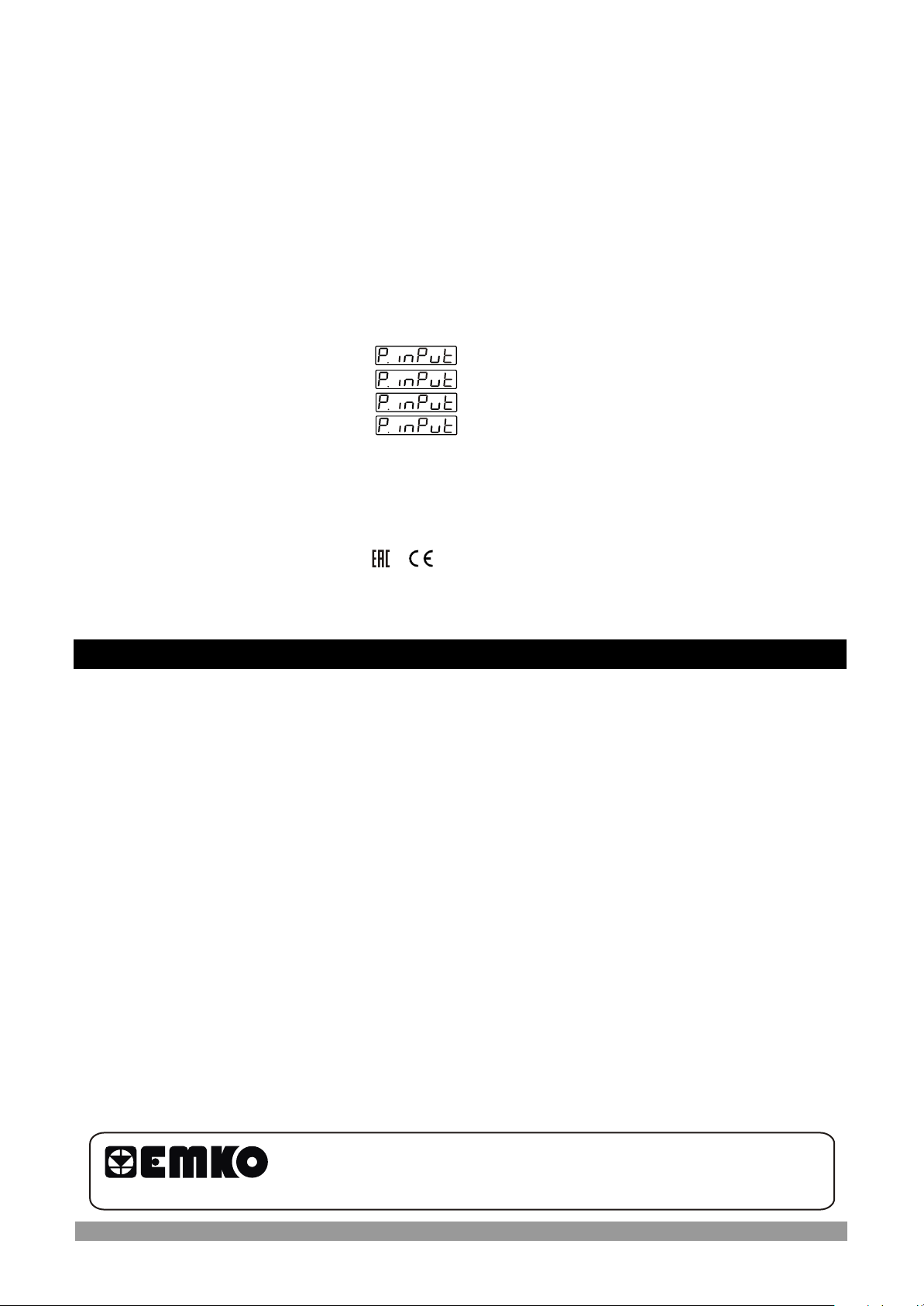
Maximum Input Frequency : = 0 , 1 , 2 with 20000 Hz
= 3 , 4 with 20000 Hz
= 5 , 6 with 12000 Hz
= 7 with 10000 Hz
Output Type : Relay Output on Resistive Load 5A@250VV
100.000 operation (Full Load)
Actual Value Display : 10,8 mm Red 6 digit LED Display
Set Display : 8 mm Green 6 digit LED Display
LED Displays : SV (Set value) , OP (Control output) LEDs
Approvals : ,
8. Other Informations
Manufacturer Information:
Emko Elektronik Sanayi ve Ticaret A.Þ.
Demirtaþ Organize Sanayi Bölgesi Karanfil Sk. No:6 16369
BURSA/TURKEY
Phone : +90 224 261 1900
Fax : +90 224 261 1912
Repair and Maintenance Service Information:
Emko Elektronik Sanayi ve Ticaret A.Þ.
Demirtaþ Organize Sanayi Bölgesi Karanfil Sk. No:6 16369
BURSA/TURKEY
Your Technology Partner
Thank you very much for your preference to use Emko Elektronik
Products.
www.emkoelektronik.com.tr
48
 Loading...