

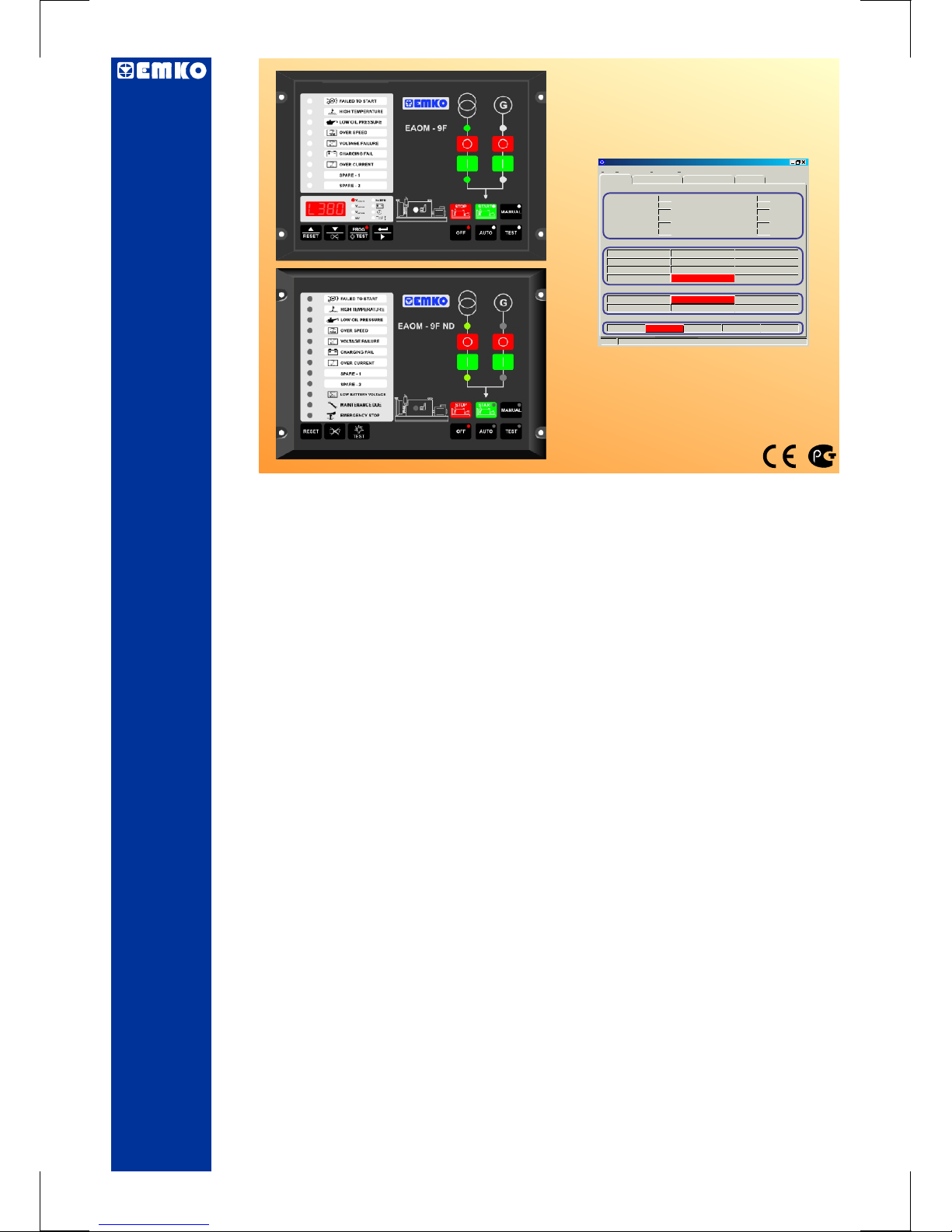
EAOM-9F & EAOM-9F ND Automatic Transfer Switch Controllers, Flat Type
-
-
-
-
-
-
-
-
-
-
-
- Monitors (Only EAOM-9F)
3-phase mains supply voltage Battery voltage
Alternator voltage Engine running time
Alternator frequency Error Indication
Engine Speed Program Parameters
- Controls
Engine fuel supply or Engine Stopping Load transfer on mains failure
Starter motor Return to mains
Alarm horn Mains contactor
Preheat Generator contactor
Automatic generator start
- Fail Monitoring
Mains Supply Voltage Engine Start
Alternator Voltage and Frequency Alternator Over Current
Engine Speed Emergency Stop
Engine Temperature Maintenance Due
Oil Pressure Low Battery Voltage
Charge Generator Voltage
- Programming using the buttons and display on the front panel or RS-232
communication port, using PC based software.
Protection, control and metering
Automatic engine start/stop and load transfer
Automatic shutdown on fault condition
LED status and fault indication
Simple push-button controlled operation
Manual, automatic and test mode control
Two user-configurable inputs
One user-configurable output
Fully programmable
RS-232 communication port
Standard modem communication
Instruction Manual. ENG EAOM-9F & EAOM-9F ND 02 V00 07/07
EAOM-9F & EAOM-9F ND
Automatic Transfer Switch Controllers,
Flat Type
Technician Parameters
EAOM-9F / 9F ND SOFT
File Programming
Adjustment
Settings About
COM1 Communication
Observation
Operator Parameters
Measurement Values
Mains Voltage (L12)
Mains Voltage (L1N)
Mains Voltage (L23)
Mains Voltage (L2N)
Mains Voltage (L31)
Mains Voltage (L3N)
Vac
Vac
Vac
Vac
Vac
Vac
Generator UV Voltage
Generator Frequency
Battery Voltage
Maintenance Time
Exercise Time
Running Time
0
0
0
0
0
0
0
0.0
11.0
0 / 0
0
0
Vac
Hz
Vdc
Hour / Day
Hour
Hour
Failures
Start Failure
High Temperature
Low oil Pressure
Battery Fail
Over Speed
Generator Voltage Failure
Charge Genarator Failure
Emergency Stop
Over Current
Spare-1
Spare-2
Routine Maintenance
Outputs
Mains Contactor Out
Generator Contactor Out
Configurable Out Output1
Selenoid Out
Start Out
Horn Out
Modes
Off
Auto
Manual Test Program

2
Instruction manual of EAOM-9F EAOM-9F consists of two main sections.
Explanation of these sections are below. Also, there is another section which include technical
specifications of the device. All titles and page numbers in instruction manual are in
“CONTENTS” section. User can reach to any title with section number.
Installation:
In this section, physical dimensions of the device, panel mounting, electrical wiring,
physical and electrical installation of the device to the system are explained.
Operation and Parameters:
In this section, user interface of the device, how to access to the parameters, description
of the parameters are explained.
Also in these sections, there are warnings to prevent serious injury while doing the
physical and electrical mounting or using the device.
Explanation of the symbols which are used in these sections are given below.
& ND
This symbol is used to determine the dangerous situations as a result of an electric
shock. User must pay attention to these warnings definitely.
a
c
This symbol is used for safety warnings. User must pay attention to these
warnings.
This symbol is used to determine the important notes about functions and usage of
the device.
ABOUT INSTRUCTION MANUAL
i
This symbol is used for VDC
This symbol is used for VAC
Z
V

3
CONTENTS
Page 6
Page 14
Page 9
Page 18
Page 26
1.PREFACE............................................................................................................................................
1.1 GENERAL SPECIFICATIONS
1.2 WARRANTY
1.3 MAINTENANCE
2.INSTALLATION....................................................................................................................................
2.1 GENERAL DESCRIPTION
2.2 DIMENSIONS
2.3 PANEL CUT-OUT
2.4 ENVIRONMENTAL RATINGS
2.5 PANEL MOUNTING
2.6 INSTALLATION FIXING SCREWS
2.7 REMOVING FROM THE PANEL
3.ELECTRICAL WIRINGS......................................................................................................................
3.1 TERMINAL LAYOUT AND CONNECTION INSTRUCTIONS
3.2 ELECTRICAL WIRING DIAGRAM
4.RS-232 SERIAL INTERFACE, PROGRAMMING THE DEVICE OVER PC OR MODEM...................
4.1 CABLE CONNECTION BETWEEN RS-232 TERMINAL OF THE DEVICE AND PC
4.2 CABLE CONNECTION BETWEEN RS-232 TERMINAL OF THE DEVICE AND MODEM
4.3 PC INTERFACE
4.3.1 TECHNICAL SPECIFICATIONS
4.3.2 INSTALLATION INSTRUCTIONS
4.3.2.1 MINIMUM SYSTEM REQUIREMENTS
4.3.3 INSTALLING EAOM-9F / EAOM-9F SOFTWARE
4.3.4 USING OF EAOM-9F / EAOM-9F COMMUNICATION SOFTWARE
4.3.5 DESCRIPTION
4.3.6 OBSERVATION WINDOW
4.3.7 OPERATOR PARAMETERS WINDOW
4.3.8 TECHNICIAN PARAMETERS WINDOW
4.3.9 MAIN MENU
4.3.9.1 FILE
4.3.9.2 PROGRAMMING
4.3.9.3 SETTINGS
4.3.10 ENTERING TO THE OPERATOR PARAMETERS WINDOW
4.3.11 ENTERING TO THE TECHNICIAN PARAMETERS WINDOW
4.3.12 ENTERING TO THE ADJUSTMENT WINDOW
4.3.13 LOAD THE CONFIGURATION FILE FROM DISC
4.3.14 SAVE THE CONFIGURATION FILE TO THE DISC
4.3.15 UPLOAD
4.3.16 DOWNLOAD
5.PARAMETERS.....................................................................................................................................
5.1.14 “POWER ON” DEFAULT MODE CONFIGURATION
5.1.15 CONFIGURABLE OUTPUT
5.1.16 MAINTENANCE INDICATION
5.1.17 OPERATOR PASSWORD
5.1.18 TECHNICIAN PASSWORD
5.1.19 ENGINE EXERCISE FUNCTION
5.1.20 MAINS CONTACTOR CONTROL SELECTION
ND
ND
5.1. PROGRAM FUNCTIONS
5.1.1 MAINS VOLTAGE
5.1.2 ALTERNATOR VOLTAGE
5.1.3 ALTERNATOR FREQUENCY
5.1.4 ENGINE COOLING TIME
5.1.5 BATTERY VOLTAGE LOWER LIMIT
5.1.6 ENGINE STARTING
5.1.7 ENGINE STARTED SIGNALS
5.1.8 SPEED SENSING INPUT SELECTION
5.1.9 STOP / FUEL SOLENOID SELECTION
5.1.10 STOP MAGNET ENERGISING TIME
5.1.11 OIL PRESSURE BY-PASS TIME
5.1.12 CONTROL ON DELAY
5.1.13 CONFIGURABLE INPUTS

5.1.21 HORN BLINK SELECTION
5.1.24 REMOTE CONTROL MODE SELECTION
5.2 CHANGING and SAVING OPERATOR PARAMETER VALUE
5.3 CHANGING and SAVING TECHNICIAN PARAMETER VALUE
9. FAULT FINDING.................................................................................................................................
10.PROGRAMMABLE PARAMETERS..................................................................................................
11.SPECIFICATIONS..............................................................................................................................
5.1.22 ENGINE STARTING DELAY
5.1.23 ENGINE FUEL SELECTION AND FUEL-STARTER DELAY TIME
6. COMMISSIONING..............................................................................................................................
6.1 MANUAL OPERATION
6.2 AUTO OPERATION
6.3 TEST MODE OPERATION
7. LAMP TEST.........................................................................................................................................
8. OPERATION.......................................................................................................................................
8.1 FRONT PANEL DESCRIPTION
8.2 DISPLAY MODE INDICATORS
8.3 MODE TRANSITION
8.4 MANUAL START
8.5 MANUAL STOP
8.6 AUTO OPERATION
8.7 TEST OPERATION
8.8 ENGINE EXERCISING
9.1 FAULT INDICATIONS
9.1.1 FAILED TO START LED
9.1.2 HIGH TEMPERATURE LED
9.1.3 LOW OIL PRESSURE LED
9.1.4 CHARGE GENERATOR FAILURE LED
9.1.5 OVER SPEED LED
9.1.6 GENERATOR VOLTAGE FAILURE LED
9.1.7 OVER CURRENT LED
9.1.8 CONFIGURABLE INPUT-1 AND 2 LED
9.1.9 EMERGENCY STOP MESSAGE LED
9.1.10 LOW BATTERY VOLTAGE MESSAGE LED
9.1.11 MAINTENANCE TIME MESSAGE LED
4
Page 39
Page 44
Page 49
Page 40
Page 41
Page 47

5
Manufacturer Company Name : Emko Elektronik A.S.
Manufacturer Company Address: DOSAB, Karanfil Sokak, No:6, 16369 Bursa, Turkiye
The manufacturer hereby declares that the product conforms to the following
standards and conditions.
Product Name :
Model Number :
Type Number : EAOM-9F EAOM-9F
Product Category : Electrical equipment for measurement, control and
laboratory use
Conforms to the following directives :
Electrical control equipment for generating sets
EAOM-9F & EAOM-9F ND
& ND
EMC : BS EN 50081-2, EMC Generic Emission Standard for industrial
equipment
BS EN 50082-2, EMC Generic Immunity Standard for industrial
equipment
Electrical Safety : EN 61010-1, Safety Requirements for electrical equipment for
measurement, control and laboratory use
EU DECLARATION OF CONFORMITY

1. PREFACE
6
The provides for automatic transfer of a load from mains to generator
in the event of a mains supply failure. Intended for unattended operation, it is able to detect failure
of any phase of the mains and to start and switch over to a generator if the mains voltage goes
outside pre-set limits. Both automatic and manual control is possible. A test mode is also
available which allows the generator to be run without taking the load.
The unit monitors generator operation and gives warning of any faults that are detected, by LED
indicators. The unit monitors:
Mains supply voltage
Alternator voltage and frequency
Engine temperature
Oil Pressure
Charge generator voltage
Engine speed
It controls:
Engine fuel supply or engine stopping Mains and Generator contactors
Starter motor
Alarm horn
Automatic generator start and load transfer
on mains failure
EAOM-9F Features a four-digit, seven-segment LED display, providing extensive monitoring of
unit and generator parameters, including:
Three phase mains voltage
Alternator output voltage and frequency
Engine RPM
Battery voltage
Elapsed time
Error indication
Engine running time
Program Parameters
EAOM-9F ND has no display, offers identical functionality and programming via RS-232, and can
be used where electrical and engine metering is already in place.
The unit is extensively programmable through the front panel, with password protection on two
levels. Operational parameters can also be monitored and controlled from a PC via a built-in RS232 port.
If the engine fails to start on the first attempt, further attempts are made up to a programmed
number of times or until successful.
If a fault is detected, the unit shuts down the engine and indicates the failure by flashing a relevant
fault LED.
Emergency stop and remote inhibit inputs provide for remote control of the engine.Configurable
inputs can be programmed to perform many functions, such as warning alarms,stopping the
engine or disconnecting the load.
A configurable output can be programmed for various functions, including alarms, operation as a
pre-heat output, indication of engine running status, and indication that the product is in
Automatic mode.
The unit can be programmed using the buttons and display on the front panel. Refer to Section 5
Parameters for details. Alternatively, the unit can be programmed via the RS-232 communication
port, using PC based software.
EAOM-9F / EAOM-9F ND
Over Current
Emergency Stop
Maintenance Due
Low Battery Voltage
Engine Start
Alternator
Preheat
Automatic generator start
Return to mains
EAOM-9F/ EAOM-9F ND can communicate with this software
over modem.

1.1 General Specifications
7
+BATTERY
N
MAINS L1
MAINS L2
MAINS L3
GEN. L1
N
BATTERY
VOLTAGE
SENSING
MAINS
&
GENERATOR
VOLTAGE
SENSING
&
CONDITIONING
FREQUENCY
SENSING
FROM
GENERATOR
VOLTAGE
FREQUENCY
SENSING
FROM
MAGNETIC
PICK-UP
FAILURE
&
CONTROL
INPUTS
PUSH
BUTTONS
MAGNETIC
PICK-UP
ANALOG
TO
DIGITAL
CONVERTER
COUNTER
&
TIMER
MICROCONTROLLER
TRANSISTOR
OUTPUTS
POWER
SUPPLY
FAILURE &
STATUS
INDICATORS
RS-232+MODEM
COMM.

8
1.2 Warranty
EMKO Elektronik warrants that the equipment delivered is free from defects in material and
workmanship. This warranty is provided for a period of two years. The warranty period starts from
the delivery date. This warranty is in force if duty and responsibilities which are determined in
warranty document and instruction manual performs by the customer completely.
1.3 Maintenance
Repairs should only be performed by trained and specialized personnel. Cut power to the device
before accessing internal parts.
Do not clean the case with hydrocarbon-based solvents (Petrol, Trichlorethylene etc.). Use of
these solvents can reduce the mechanical reliability of the device. Use a cloth dampened in ethyl
alcohol or water to clean the external plastic case.

9
Carefully unpack the unit and check for damage to the unit or to the cables supplied.
Retain the packing in case of future need, e.g. returning the unit for calibration.
Check the contents, as follows:
• One EAOM-9F / EAOM-9F ND unit.
• Operating Manual.
• Screw fixings.
• RS-232 Cable.
Before commencing installation:
• Disconnect all electrical power to the machine.
• Make sure the machine cannot operate during installation.
• Follow all of the machine manufacturers' safety warnings.
• Read and follow all installation instructions.
Report any shortage or damage to your local sales office as soon as possible.
A visual inspection of this product for possible damage occured during shipment is
recommended before installation. It is your responsibility to ensure that qualified
mechanical and electrical technicians install this product.
Be sure to use the rated power supply voltage to protect the unit against damage and to
prevent failure.
Keep the power off until all of the wiring is completed so that electric shock and trouble
with the unit can be prevented.
Never attempt to disassemble, modify or repair this unit. Tampering with the unit may
results in malfunction, electric shock or fire.
Do not use the unit in combustible or explosive gaseous atmospheres.
During the equipment is putted in hole on the metal panel while mechanical installation
some metal burrs can cause injury on hands, you must be careful.
Montage of the product on a system must be done with it’s own fixing screws. Do not do
the montage of the device with inappropriate fixing screws. Be sure that device will not fall
while doing the montage.
It is your responsibility if this equipment is used in a manner not specified in this
instruction manual.
Before beginning installation of this product, please read the instruction
manual and warnings below carefully.
2. INSTALLATION
c
9
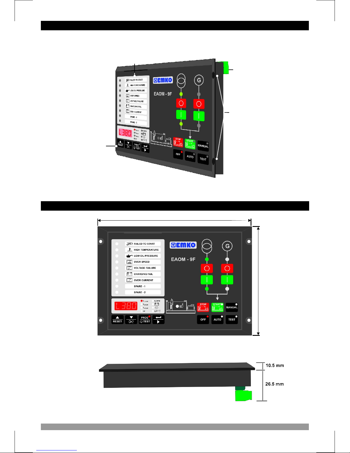
204mm
144mm
10
2.1 General Description
2.2 Dimensions
Front Panel
IP65 protection
NEMA4X
Label
Pocket
Mounting
Holes
Connection
Terminals
Þekil 2.2. Side View
Figure 2.1. Front View
96mm

11
2.3 Panel Cut-Out
Operating Temperature : -25°C to 70°C
Max. Operating Humidity : 90% Rh (non-condensing)
Altitude : Up to 2000m.
Operating Conditions
Forbidden Conditions:
Corrosive atmosphere
Explosive atmosphere
Home applications (The unit is only for industrial applications)
2.4 Environmental Ratings
c
17.25
m
m17.25
m
m
R=
4.
5m
m
R=
4.
5m
m
=4
5
R . m
m=4
5
R . m
m
17
.2
5m
m17
.2
5m
m
m
5
m
m
5
m
5mm5mm
R=4.5mmR=4.5mm
R=4.5mmR=4.5mm
186 mm186 mm
1
0
3
.5 mm1
0
3
.5 mm
196 mm196 mm
13
8
mm13
8
mm
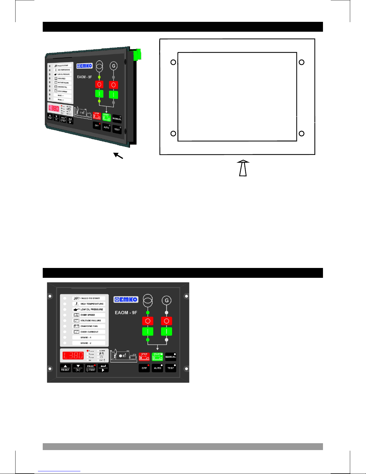
12
During installation into a metal panel, care should be taken to avoid injury from
metal burrs which might be present. The equipment can loosen from vibration
and become dislodged if installation parts are not properly tightened. These
precautions for the safety of the person who does the panel mounting.
1. Before mounting the device in your panel, make sure that the cut-out is of the right size
2. Make sure that the diameter of the holes are of the right size and coordinate of the holes are
true.
3. Check front panel gasket position
4. Insert the device through the cut-out. If the mounting screws are on the unit, put out them
before inserting the unit to the panel.
2.5 Panel Mounting
c
1
3
2
22
2
4
The unit is designed for panel
mounting.
1. Insert the unit in the panel cut-out from
the front side.
2. Insert the fixings through the mounting
holes and tighten the fixing screws to
secure the unit against the panel.
Fixing is done by four screw
fixings
2.6 Installation Fixing Screws
Montage of the unit to a system must be done with it’s own fixing screws. Do not do the
montage of the device with inappropriate fixing screws. Be sure that device will not fall
while doing the montage.
During mechanical installation, beware of any sharp burrs on the metal panel
aperture. Ensure that the fixings are properly tightened to prevent the fixings
becoming loose due to panel vibration.
c
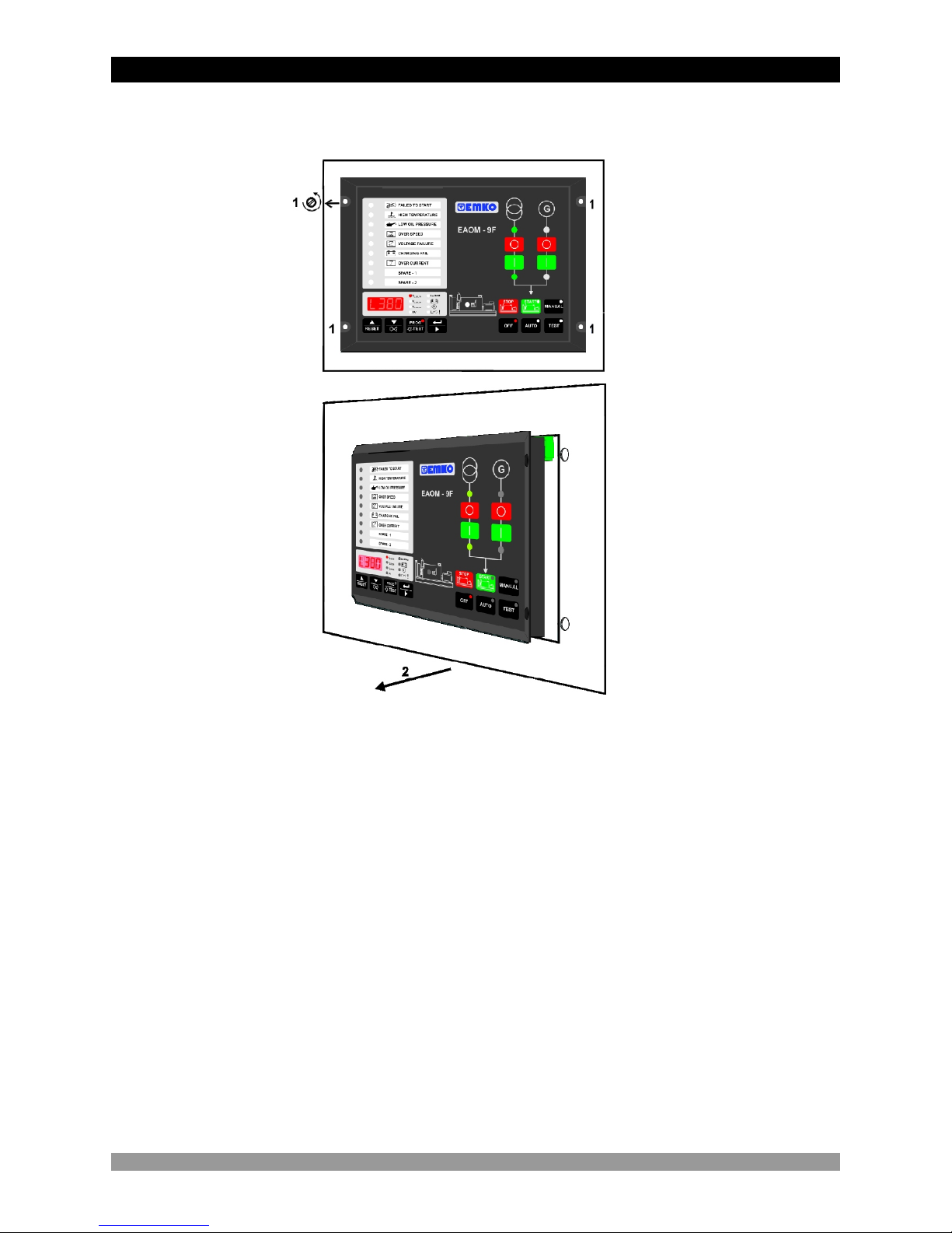
1. Loosen the screws.
2. Pull the unit through the front side of the panel
Before starting to remove the unit from panel, power off the unit and the related
system.
2.7 Removing from the Panel
c
13

3.1 Terminal Layout and Connection Instructions
14
The Remote Inhibit input is only active when the unit is in the AUTO Mode. When
asserted, the engine will not start up. If the engine was already running when this input becomes
active, the engine will shut down. The generator operates normally when the input is open circuit.
While installing the unit, battery voltage range must be controlled and appropriate battery
voltage must be applied to the unit. Controlling prevents damages in unit and system and
possible accidents as a result of incorrect battery voltage.
Switch on the battery voltage only after that all the electrical connections have been
completed.
External fuse is recommended.
In case of failure it is suggested to return the instrument to the manufacturer for repair.
You must ensure that the device is correctly configured for your application. Incorrect
configuration could result in damage to the process being controlled, and/or personal injury. It is
your responsibility, as the installer, to ensure that the configuration is correct. Device parameters
has factory default values. These parameters must be set according to the system’s needs.
There is severe danger for human life in the case of unauthorized intervention.
Only qualified personnel and trained technicians should work on this equipment.
Do not open
or dismantle the product enclosure.
This
equipment contains internal circuits with voltage dangerous to human life.
c
1 (5V)
2 (Tx)
3 (Rx)
4 (GND)
RS 232
COMMUNICATION
INTERFACE
•••
•
aa
cc
OPEN COLLECTOR TRANSISTOR OUTPUTS
MAX. 500 mA
CE
3. ELECTRICAL WIRINGS

3.2 Electrical Wiring Diagram
15
Single Phase Electrical Wiring
Three Phase Electrical Wiring
Ensure the battery supply is of the correct polarity and that the battery negative rail is grounded. The connectors can be unplugged from
the rear of the unit for convenience and to speed up installation.
The fuses should be as follows:
FUSE-1, FUSE 3, FUSE-4, FUSE-5, FUSE-6 1 A. T
FUSE-2 2 A. T
c
MAINS CONTACTOR
N
L
MAINS
L N
LOAD
GENERATOR CONTACTOR
R-5
MAINS VOLTAGE
R-6
GENERATOR VOLTAGE
GENERATOR
N
L
- BATTERY
FUSE-3
U -6
F
SE
+ BATTERY
FUSE-1
START OUTPUT
HORN OUTPUT
CONFIGURABLE OUTPUT
GEN. CONTACTOR
CONTROL OUTPUT
MAINS CONTACTOR
CONTROL OUTPUT
SOLENOID OUTPUT
FUSE-2
BATTERY
R-1
R-2
R-3
R-4 R-5
D+(W.L)
CHARGE GENERATOR
LOW OIL PRESSURE
HIGH TEMPERATURE
OVER CURRENT
E.STOP
REMOTE INHIBIT
CONFIGURABLE
FAILURE INPUT-1
CONFIGURABLE
FAILURE INPUT-2
Magnetic
Pickup
(up to 10kHz)
BATTERY NEGATIVE MUST BE GROUNDED
R-6
MAINS CONTACTOR
N
L1
L2
L3
MAINS
L3 L2 L1 N
LOAD
GENERATOR CONTACTOR
R-5
MAINS VOLTAGE
R-6
GENERATOR VOLTAGE
GENERATOR
N
L1
L2
L3
- BATTERY
FUSE-3
FUSE-4
FUSE-5
FU
S
E
-
6
+ BATTERY
FUSE-1
START OUTPUT
HORN OUTPUT
CONFIGURABLE
CONTROL OUTPUT
CONTACTOR
CONTROL OUTPUT
SOLENOID OUTPUT
FUSE-2
BATTERY
R-1
R-2
R-3
R-4
R-5
CHARGE GENERATOR
LOW OIL PRESSURE
HIGH TEMPERATURE
OVER CURRENT
E.STOP
REMOTE INHIBIT
CONFIGURABLE
FAILURE INPUT-1
CONFIGURABLE
FAILURE INPUT-2
Magnetic
Pickup
(up to 10kHz)
BATTERY NEGATIVE MUST BE GROUNDED
R-6
1- Connect the unit as shown in the appropriate diagram above. Be sure to connect the battery supply the right way round and
battery negative should be grounded. The connectors can be unplugged from the rear of the unit to facilitate connection.
2- Screened cable must be used for connecting the Magnetic Pickup, ensuring that the screen is grounded at one end ONLY.
+
24
23
22 21
20 19 18
17
16 158
7
c
1
c
1
c
2
++
c
1
c
1
c
2
4
3
2 1
5
6
12 11
10 9
13
14
123
4
5
6
13
14 12 11
10 9 8
7
24
23
22 21
20 19 18
17
16 15
GEN. CONTACTOR
OUTPUT
MAINS
D+(W.L)
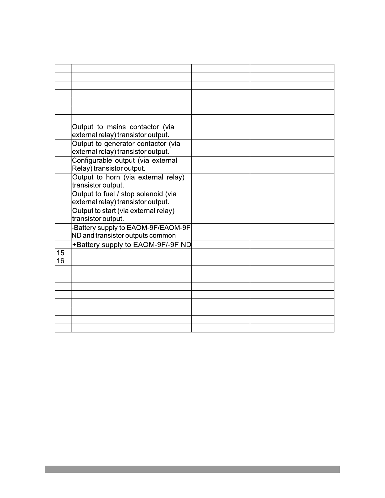
Table 2.1 Unit wiring
16
Mains PEN conductor
2.5
Description
Cable Size (mm)
Notes
Mains voltage input (L1)
2.5
3 phase applications only
Mains voltage input (L2)
2.5
2.5
Mains voltage input (L3)
3 phase applications only
Alternator PEN conductor
2.5
Alternator voltage input (L1)
2.5
7
1 500 mAZ
8 1 500 mAZ
19 500 mAZ
110 500 mAZ
111 500 mAZ
112 500 mAZ
2.5 13
Supplies to unit.
2.5
Supplies to unit
1
Input from magnetic pick-up
Configurable failure input-2
1
Switch to 0 VZ (NO)
Configurable failure input-1
Switch to 0 VZ (NO)
1
Input from remote inhibit
Switch to 0 VZ (NO)
1
20
Input from emergency stop
1
21
Input from high current Switch to 0 VZ (NO)
1
22
Input from high temperature
1
Switch to 0 VZ (NO)
23
Input form low oil pressure Switch to 0 VZ (NC)
1
24
Input from charge generator
1
Table 2.1 shows the connections and recommended cable sizes. Table 2.2 describes the
functions of the connections.
Pin
1
2
3
4
5
6
14
17
18
19
Switch to 0 VZ (NC)

Table 2.2 Unit wiring description
Pin Function
Mains PEN conductor EAOM-9F / EAOM-9F ND
6
7
Alternator contactor transistor output (via external relay)
9
Horn transistor output. Alarm output. (via external relay)
11
Start transistor output. Controls starter motor. (via external relay)
17
19
20
21
22
23
17
18
1
5
8
10
12
13
14
24
Mains contactor transistor output. For mains contactor normally closed or
normally open can be selected. (via external relay)
Configurable failure output. Can be programmed to provide transistor output
closure when : alarm occurs, engine is running, unit is ready for automatic
operation or preheat function. (Via external relay)
Fuel / Stop transistor output. Controls fuel to engine or control engine
stopping (via external relay)
18
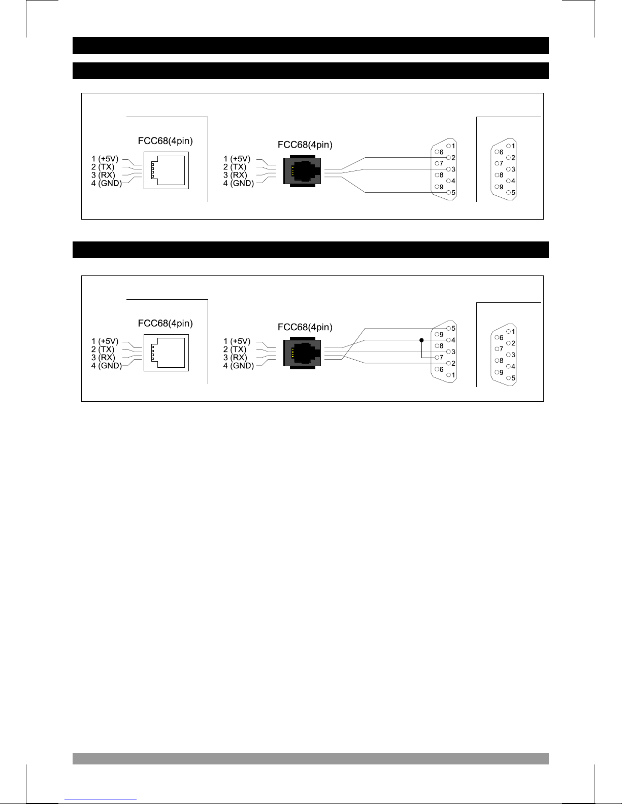
4.RS-232 SERIAL INTERFACE, PROGRAMMING THE DEVICE OVER PC OR MODEM
4.1 Cable Connection Between RS-232 Terminal of the Device and PC
9 pin D connector
female
EAOM-9F
Standard communication cable
9 pin D connector
male
EAOM-9F
MODEM communication cable
Green
Yellow
White
Brown
Brown
White
Green
Note: For 9600 baud rate, cable length must be maximum 10 meters.
PC
MODEM
9 pin D connector
male
9 pin D connector
female
4.2 Cable Connection Between RS-232 Terminal of the Device and Modem

19
The PC interface kit comprises of a 9 pin D connector/FCC68(4 pin) connection lead with 2
meters of cable, and the optional PC Software (Supplied on CD-ROM)
RS-232 non-isolated Serial interface
9600 Baud Rate
8 data bits, No Parity,1 Stop Bit
Maximum allowable cable length is 10 meters
Processor : 486 66MHZ
Operating Systems : Windows 95/98/XP, Windows NT, Windows 2000
Ram : 16 Mbyte
Monitor : 14’’ SVGA (640x480 resolution)
Fixed Disk Free Space : 5 Mbyte
Disk Drive : CD-ROM
Communication : An RS-232 communication port is needed to communicate with the
EAOM-9F / EAOM-9F ND unit
Insert the software CD into the CD-ROM drive on the PC. CD will autostart, then select E AOM-9F
/ EAOM-9F ND Install from the menu .
Press the windows START button icon, then select EAOM-9F / EAOM-9F ND SW Þ EAOM-9F /
EAOM-9F ND from the program Menu.
EAOM-9F / EAOM-9F ND unit communicates with the PC using RS-232 communications. The
PC software allows the EAOM-9F / EAOM-9F ND unit’s parameters and status information to be
displayed on the PC screen. Operator and Technician parameters can be viewed. Parameters
are password protected.
There are four windows in EAOM-9F / EAOM-9F ND PC SW: Observation Window, Operator
Parameters Window,Technician Parameters Window and Adjustment Window.
4.3 PC Interface
4.3.1 Technical Specifications
4.3.2 Installation Instruction
4.3.2.1 Minimum System Requirements
4.3.3 Installing EAOM-9F / EAOM-9F ND Software
4.3.4 Using Of EAOM-9F / EAOM-9F ND Communication Software
4.3.5 Description

20
When the program runs firstly, a window is shown to determine how the connection will be
established: over modem or RS-232 communication port. This selection is made with the
‘Connect with Modem’ check box. If the comport settings are correct, when ‘Connect’ button is
pressed, connection is established. With ‘Add New Phone Number’ button, user can access to
the window below and save the location name and phone number for using to connect with
modem.
4.3.6 Observation Window
Firstly, enter phone number and location
name (It is used to remember where the
phone number belongs) and press ‘Ok’
button for saving these values.
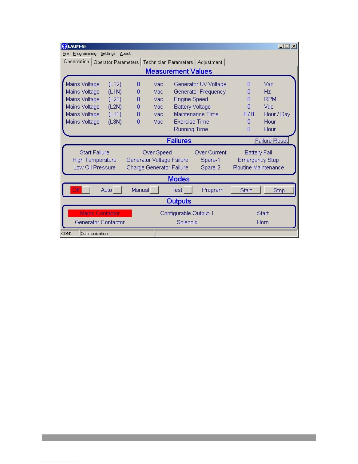
When the connection is established, main screen is shown.
21
Measurement Values
Mains Voltage
Generator Voltage
Generator Frequency
Battery Voltage
Maintenance Hour
Running Time
Exercise Time
Failures
Start Failure
High Temperature
Low Oil Pressure
Over Speed
Generator Voltage Failure
Charge Generator Failure
Over Current
Configurable Inputs 1 & 2
Battery Fail
Emergency Stop
Routine Maintenance
Outputs
Mains Contactor Output
Generator Contactor Output
Configurable Output-1
Solenoid output
Start output
Horn output
Serial communication port (RS-232)
Modes
Off
Auto
Manual
Test
Program
22
Operator parameters can be viewed and edited. Parameters are password protected. When the
operator password is entered, it is compared with operator password that is registered inside the
EAOM-9F / EAOM-9F ND unit.
All parameters can be viewed and edited in this window. Parameters are password protected.
When the technician password is entered, it is compared with technician password that is
registered inside the EAOM-9F / EAOM-9F ND unit.
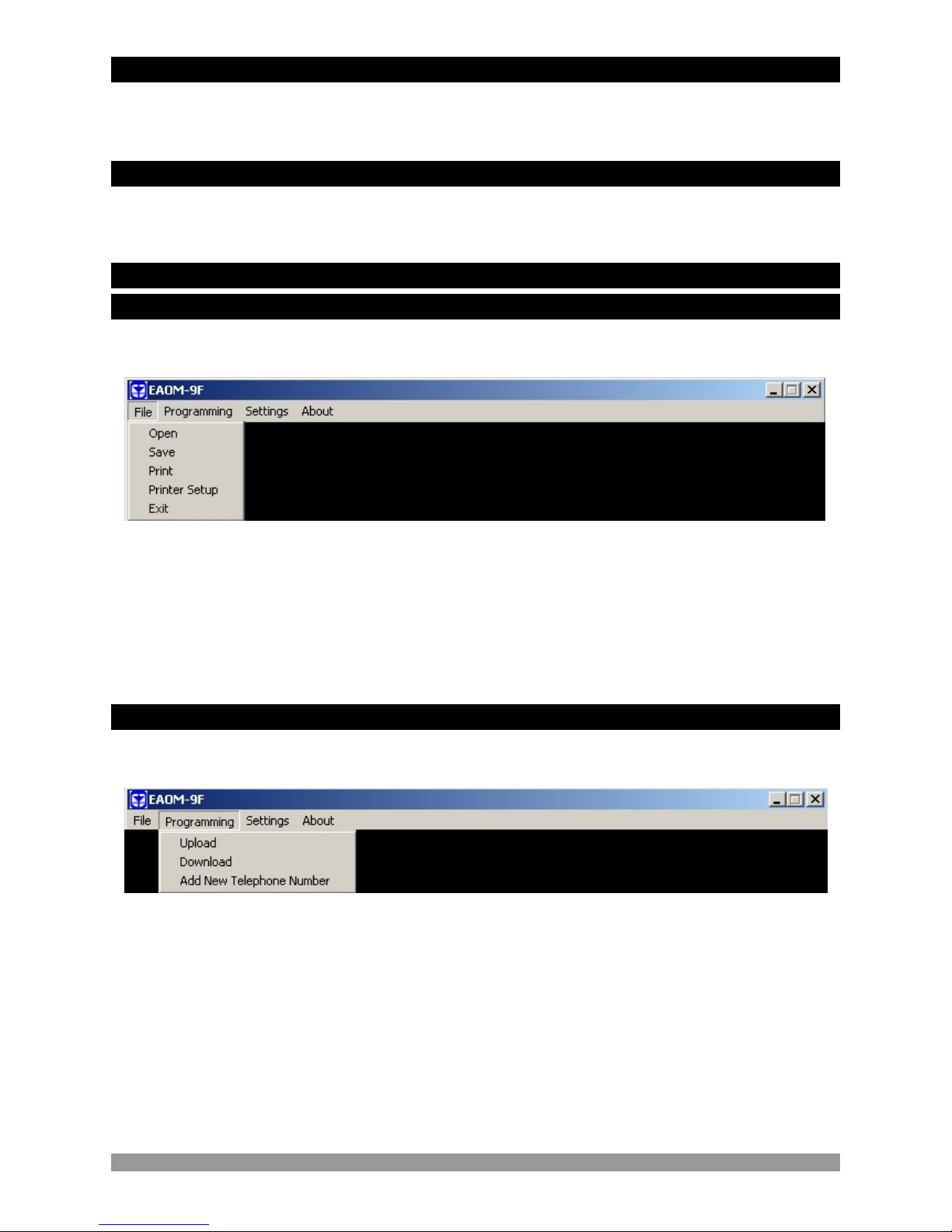
With this menu, a configuration file can be opened, parameters can be saved, printed and printer
setings can be changed.
Open :This menu allows the user to load the registered configuration files to the PC.
Save :This menu allows the user to save the parameters with a name defined by
user.
Print :This menu allows the user to print the parameters.
Printer Setup:This menu allows the user to select the printer that is connected to network or PC
and change the configuration of the printer.
Exit :Exit the program.
This menu is active if operator or technician parameters page is accessed. With this menu,
parameters can be read from the device or write to the device.
Download : With this menu user can load parameters from PC to EAOM-9F / EAOM-9F ND .
Upload : User can load the parameters stored on EAOM-9F / EAOM-9F ND unit to PC.
Add New Phone Number : User can be saved the phone number which is used for connecting
with the modem.
4.3.7 Operator Parameters Window
4.3.8 Technician Parameters Window
4.3.9 MAIN MENU
4.3.9.1 FILE
4.3.9.2 PROGRAMMING

Communication Port Settings: With this menu, user can determine the serial port
configurations of the PC
Language: Turkish or English can be selected.
4.3.9.3 Settings
Connect: With this menu, the window below is observed. According to the ‘Connect with Modem’
check status, connection can be establish over RS-232 port or modem. If the comport settings
are done correctly, when the ‘Connect’ button is pressed, connection is established.
Disconnect: If the connection is established over modem or RS-232 port, connection can be cut
off with this selection.
Click Operator Parameter tab. Enter the operator password. If the password is correct, operator
parameters will be viewed.
4.3.10 Accessing to the Operator Parameters Page
23

24
Click Technician Parameter tab. Enter the technician password. If password is correct, all
parameters will be viewed.
4.3.11 Accessing to the Technician Parameters Page
Click Adjustment tab. Enter the technician password. If the password is correct, adjustment page
will be shown.
4.3.12 Accessing to the Adjustment Page
Click 'Open' in File menu. Choose configuration file which includes operator or technician
parameters on Open Dialog Box. When the user clicks the 'Open' button on the Open Dialog Box,
parameters will be transferred to PC window.
4.3.13 Load the Configuration File From Disc
4.3.14 Save the Configuration File to the Disc
Click 'Save' in File menu. After choosing where to save the file, enter the file name. When the user
clicks the 'Save' button on Save Dialog Box, all parameters will be saved to the file.

For loading parameters from EAOM-9F / EAOM-9F ND unit to PC follow the steps below. If user is
in operator parameters window, only operator parameters will be viewed. If user is in Technician
Parameters Window, all parameters will be viewed. Press 'Upload' in Program menu. While
loading the parameters, the hour-glass cursor is displayed. Please wait for the upload operation
to complete, when the cursor returns to normal.
For loading parameters from PC to EAOM-9F / EAOM-9F ND follow the steps below. If user is in
operator parameters window, only operator parameters will be loaded. If user is in Technician
Parameters Window, all parameters will be loaded. Press 'Download' in Program menu. While
loading the parameters, the hour-glass cursor is displayed. Please wait for the download
operation to complete, when the cursor returns to normal.
25
4.3.15 Upload
4.3.16 Download

The unit is extensively programmable through the front panel and via PC software.
Table 4 Programmable function definitions
Engine started signal
P26.0
P26.2
P26.3
0=No, 1=Yes
Alternator voltage limit for crank disconnection
P35
600
60
60
60
60
600
600
600
600
30.0 75.0
0 999
0000 9999
VV
VV
VV
VV
VV
60
Hz
Day
Hour
1 10
Number
0 99
Minute
0 999
Second
0 30
Minute
0 99
Second
0 999
Hour
0 999
Minute
500 5000
Rpm
1 1000
Number
7.2 24.0
VZ
0.1 25.0
Second
0 99
Second
5
99
Second
40 360
VV
20.0 45.0
Hz
0 99
Second
0 99
Second
0.0 10.0
Second
0.0 10.0
Second
0/1
0/1
0/1
0/1
Charge Generator
Speed
Alternator Voltage
Oil Pressure
P26.1
50.0/60.0
Hz
1/3
Stop / Fuel
0=Off,1=Auto
Number
Min
Default
Unit
Definition of Parameter
Max
Mains Voltage Connection Level
Mains Voltage Disconnection Level
Mains Voltage Upper Limit
Alternator Voltage Lower Limit
Alternator Voltage Upper Limit
Speed Upper Limit
Periodic Maintenance Day Set Value(0 = dis)
Periodic Maintenance Hour Set Value(0 = dis)
Number of Starting Attempts
Engine Cooling Time(0 disable cool process)
Horn Duration (0 Continuous)
Mains Transition Delay
Preheat Time
Exercise Time (0 Disable)
Exercise Duration Time Period
Single / Three Phase Selection
Speed Sensing Input Selection
Nominal Alternator Frequency
Nominal Speed
Tooth Number
Battery Voltage Lower Limit
Mains Change Over Delay
Stop / Fuel Solenoid Selection
Stop Magnet Energising Time
Starting Attempt Duration
Speed Limit for Crank Disconnection
Oil Pressure By-Pass Time
Control on Delay
Alternator Voltage Fault Control Delay
Speed Fault Control Delay
Engine running time reset
“Power ON” default mode configuration
Periodic Maintenance Hour Reset
320
300
440
320
440
53.0
365
5000
3
3
60
3
10
0
20
3
0
50.0
3000
100
8.0
1.0
Fuel
20
1
0
1
0
5
300
40.0
30
10
5.0
5.0
26
0
No
P00
P01
P02
P03
P04
P05
P06
P07
P08
P09
P10
P12
P13
P14
P15
P16
P17
P18
P19
P20
P21
P22
P23
P24
P25
P26
P28
P29
P30
P31
P32
P33
P34
P36
Press ‘Silence Alarm’ button to reset
0=Alternator Signal
(Internal)
1=Magnetic Pickup
Enter technician password to reset
time to “0” (zero)
5. PARAMETERS
0=None, 1=Exists
Horn Blink Selection
1P11
0.0
25.0
Second
Engine Starting Delay
0.0
P27

27
Normal / Fail safe configuration of inputs
310
Number
Min
Default
Unit
Definition of Parameter
Max
0
No
P37
0 All normal
1 Temperature Fail-safe
2 Pressure Fail-safe
3 Temp. + Pressure Fail-safe
4 Conf. Input1 Fail-safe
5 Conf. Input1 + Temp. Fail-safe
6 Conf. Input1 + Pressure Fail-safe
7 Conf. Input1 + Temp + Pressure Fail-safe
8 Conf. Input2 Fail-safe
9 Conf. Input2 + Temp. Fail-safe
10 Conf. Input2 + Pressure Fail-safe
11 Conf. Input2 + Temp + Pressure Fail-safe
12 Conf. Input1 + Conf. Input2 Fail-safe
13 Conf. Input1 + Conf. Input2 + Temp. Fail-safe
14 Conf. Input1 + Conf. Input2 + Pressure Fail-safe
15 Conf. Input1 + Conf. Input2 + Pressure + Temp.
Fail-safe
16 Current Fail-safe
17 Current + Temp. Fail-safe
18 Current + Pressure Fail-safe
19 Current + Pressure + Temp. Fail-safe
20 Current + Conf. Input1 Fail-safe
21 Current + Conf. Input1 + Temp. Fail-safe
22 Current + Conf. Input1 + Pressure Fail-safe
23 Current + Conf. Input1 + Pressure + Temp. Failsafe
24 Current + Conf. Input2 Fail-safe
25 Current + Conf. Input2 + Temp. Fail-safe
26 Current + Conf. Input2 + Pressure Fail-safe
27 Current + Conf. Input2 + Pressure + Temp. Failsafe
28 Current + Conf.Input2 + Conf.Input1 Fail-safe
29 Current + Conf. Input2 + Conf. Input1 + Temp.
Fail-safe
30 Current + Conf. Input2 + Conf. Input1 + Pressure
Fail-safe
31 Current + Conf.Input2 + Conf.Input1 + Pressure
+ Temperature

0 Force product into AUTO mode
28
100
Number
No
Min
Default
Unit
Definition of Parameter
Max
P38
0
0 10 0
Second
0 10 0
Second
Configurable Output
0 13 0
Number
Mains Contactor Selection. Number
Configurable Input-1 Delay Time
Configurable Input-2 Delay Time
0
1 Disable front panel controls
4 LED flashes and alarm sounds until reset
2 LED status indication only
3 LED flashes and alarm sounds while
input is active
5 As “4” plus engine stops
7 As “3” but only while engine running.
6 As “2” but only while engine running.
8 As “4” but only while engine running.
10 As “8” and the alternator contactor is
de-energised
Configurable Failure Input-1 Operation:
9 As “5” but only while engine running.
100
Number
P39
0
Configurable Failure Input-2 Operation:
Selections are same with P38
0 Alarm output
1 Engine running
2 Ready for automatic transfer on mains failure
3 Preheat. Active for preheat time (P13)
4 Load transfer permitted
5 Over speed shutdown output
6 Over current alarm output
7 High temperature alarm output
8 Low oil pressure alarm output
9 Maintenance due alarm output
10 Failed to start alarm output
11 Voltage failure alarm output
12 Charging fail alarm output
13 Low battery voltage alarm output
0=Mains contactor
is NO
1=Mains contactor
is NC
P40
P41
P42
P43
Number
P47
0000 9990 0000
P48
0000 9990 0000
Number
Operator Password (P00 to P16 and P47)
Technician Password (P00 to P48)
P44
1
Motor Fuel (Gas/Diesel) Selection
P45
0.0 25.0
Fuel-Starter (Diesel)/Starter-Fuel (Gas) Delay
P46
0 2 0
Remote Control Mode Selection
0=Gas
1=Diesel
0 Prevent running
1 Run without load
2 Run with load
2.0
Time

P00 Mains Voltage Connection Level
P01 Mains Voltage Disconnection Level
P02 Mains Voltage Upper Limit
P13 Mains Transition Delay
In Automatic mode, the unit uses these parameters to decide when to switch the load between the
mains supply and the alternator – assuming the alternator is providing a satisfactory output.If the
mains voltage is higher than the Upper Limit or lower than the Disconnection Level, the unit
connects the load to the generator instead of to the mains.
If the load is running on the mains and the mains voltage falls, the unit will switch the load to the
generator when the mains voltage falls below the Disconnection Level. Conversely, if the mains
voltage is low and the load is running on the generator, the unit will not restore the mains supply to
the load until the mains voltage is between Connection Level and Mains Voltage Upper Limit for
Mains Transition Delay (P13) value. This hysteresis prevents constant switching between mains
and generator as the mains varies about the switching levels. Figure 5.1 shows how, in automatic
mode, the load is transferred between mains and generator as the mains voltage varies over
time.
P10 = Engine Cooling Time
P13 = Mains Transition Delay
P23 = Mains Change Over Delay
P13 P13
2
P
3
P
3
2
P1
0
Mains Voltage
Upper Limit
Connection
Level
Disconnection
Level
Mains
Contactor
Generator
Contactor
Generator
Available
Figure 5.1
Default Values
Time
2
P 3
2
P 3
ON
OFF
ON
OFF
YES
NO
29
5.1 Program Functions
5.1.1 Mains Voltage

30
While generator is running on-load and if mains is available, load is taken to the mains. Generator
runs off-load during Engine Cooling Time (P10) to cool down before shut-down. (Figure 5.1)
If the battery voltage drops below the defined Battery Voltage Lower Limit (P22), an alarm occurs
and “Low Battery Failure” LED illuminates.
Number of Starting Attempts (P09)
Starting Attempt Duration (P28)
When the EAOM-9F / EAOM-9F ND receives an Engine Start command, it energises the start
solenoid to drive the starter motor and energises the Fuel solenoid (if selected – see Section 5.1.9
Stop/Fuel selection) Starting attempt duration (P28) defines the maximum period for the start
solenoid output is being active if one of the Engine Started Signals is not received (Refer to 5.1.7).
It makes a new attempt after a delay equal to twice the defined Starting attempt duration (P28).
Number of starting attempts (P09), defines the number of unsuccessful tries that the EAOM-9F /
EAOM-9F ND will make before abandoning the attempts. If all these attempts fail, EAOM-9F /
EAOM-9F ND will stop the starting attempts and start failure indication is displayed. Start failure
can be reset with reset button.
P05 Speed Upper Limit
P34 Speed Fault Control Delay
A fault will be reported if the alternator output frequency exceeds the upper limit for more than the
time defined as the Speed Fault Control Delay (P34). The fault will only occur if the engine has
been running for the period defined as the Control on Delay (P32). This failure immediately stops
the generating set without engine cooling time.
P03 Alternator Voltage Lower Limit
P04 Alternator Voltage Upper Limit
P33 Alternator Voltage Fault Control Delay
A fault will be reported if the alternator output voltage goes outside the window defined by the
upper and lower limits for more than the time defined as the Alternator Voltage Fault Control
Delay (P33). The fault will only occur if the engine has been running for the period defined as the
Control on Delay (P32). This failure immediately stops the generating set without Engine Cooling
Time (P10)
5.1.2 Alternator Voltage
5.1.3 Alternator Frequency
5.1.4 Engine Cooling Time (P10)
5.1.5 Battery Voltage Lower Limit (P22)
5.1.6 Engine Starting

This parameter specifies the method by which the unit monitors generator speed. The choice is
between alternator frequency and external magnetic pick-up. Speed is monitored so as to detect
when the engine has started. See Sections 5.1.3 Alternator Frequency, 5.1.7 Engine started
signals (P25) and 5.1.6 Engine Starting.
Where alternator frequency is used, Nominal Alternator Frequency (P19) and Nominal Speed
(P20) must be set correctly
Where the magnetic pick-up is used, Nominal Alternator Frequency (P19), Nominal Speed (P20)
and Tooth Number (P21) must be set correctly.
This parameter allows the use of either a Stop solenoid or a Fuel solenoid. (See Section 5.1.6
Engine Starting.)
If Fuel Solenoid selected, the fuel solenoid will be energised while the engine is running and deenergised to cut off the fuel and stop the engine.
If Stop Solenoid selected, the stop solenoid is normally de-energised and only energised to stop
the engine. The solenoid remains energised for the period defined as the Stop Magnet
Energising Time (P25).
This parameter sets the period for which the Stop solenoid is energised to stop the engine. It
applies only where parameter Stop / Fuel Solenoid Selection (P24) is set to Stop Solenoid.
This sets the delay before a Low Oil Pressure warning will be generated. The Low Oil Pressure
fault indicator will light if the oil pressure switch contact remains opened, while the engine is
running, after the period defined by parameter. This period begins when the EAOM-9F / EAOM-
9F ND has detected engine starting and has cut off the drive to the starter motor. This failure
immediately stops the generating set, without Engine Cooling Time (P10).
If the unit detects that the engine is running, it will de-energise the start solenoid to disconnect the
starter motor. Conversely, if the engine does not start after the starting attempt duration, the unit
will turn off the starter motor and wait twice of the Starting Attempt Duration (P28) then start again.
Hence, the unit must be able to detect when the engine has started. Four signals are available to
provide engine running information, as follows:
0. Charge Generator (P26.0 ); from charging generator energising coil current.
1. Speed (P26.1); if engine speed is higher than Speed Limit for Crank Disconnection (P30), pay
attention to the Speed Sensing Input Selection (P18) (Refer to 5.1.8)
2. Alternator Voltage (P26.2); if alternator voltage is higher than Alternator Voltage Limit for Crank
Disconneciton (P29)
3. Oil Pressure (P26.3); it looks if oil pressure switch is closed
It is advisable to select at least two of them - preferably 1)Engine Speed and either 0)Charge
Generator or 2) Alternator Voltage.
If any of the selected signals appears, the unit assumes that the engine has started.
31
5.1.7 Engine Started Signals (P26)
5.1.8 Speed Sensing Input Selection (P18)
5.1.9 Stop / Fuel Solenoid Selection (P24)
5.1.10 Stop Magnet Energising Time (P25)
5.1.11 Oil Pressure By-Pass Time (P31)

32
P37 Normal / Fail safe Configuration of Inputs
P38 Configurable Input-1 Operation
P39 Configurable Input-2 Operation
P40 Configurable Input-1 Delay Time
P41 Configurable Input-2 Delay Time
Temperature, Pressure, Configurable Input-1, Configurable Input-2 and Over current failure
inputs can be configured individually as a “normal” or “fail safe” input by Normal / Fail Safe
Configuration of Inputs (P37) parameter.
If the configurable input is normal, contact closure to input active,
If the configurable input is fail safe, contact open to input active,
On any of these inputs causes the horn to sound for the period programmed by Horn Duration
(P12) and lights the appropriate indicator on the panel. The EAOM-9F / EAOM-9F ND can be
configured to respond in any of eleven different ways to each one of these inputs. If the input is
active, according to the parameter selection, the events that are listed below occurs:
0. The unit changes over to AUTO mode
1. The front panel is disabled
2. The led continuously lights on with no flash
3. Indication is unlatched - the LED flashes. This input has no effect if any other alarm
condition is present.
4. Indication is latched. The LED flashes while the horn is sounding and then stays on until the
Failure Reset button is pressed.
5. As 4 in addition, the engine is shut down.
Options 6...10 are effective only while the engine is running.
6. As 2
7. As 3
8. As 4
9. As 5
10. As 8
The unit’s initial default mode is “OFF” when power is switched on. The default mode can be
configured to “AUTO” by adjusting this parameter.
Z
During the initial period after the engine has been started, there can be fluctuations in engine
speed and alternator output that could generate spurious fault indications. Control On Delay
(P32) defines a period during which any fault indications, except High Temperature, will be
ignored by the EAOM-9F / EAOM-9F ND. Also, in the event of a mains failure, transfer of the load
from mains to generator will be delayed until the end of the Control On Delay (P32) period. This
period begins when the EAOM-9F / EAOM-9F ND has detected engine starting and has cut off
the drive to the starter motor.
5.1.12 Control On Delay (P32)
5.1.13 Configurable Inputs
5.1.14 “Power ON” Default Mode Configuration(P36)

33
When active, this output provides battery voltage (12 VZ or 24 VZ) and can be programmed in
one of four different ways:
0. Alarm output. Active when any fault is reported until reset. It can be used for either
audible or visual alert.
1. Engine running. Active while the engine is running
2. Output is active after one second while the unit is in Test or Auto mode. Output is passive
when the unit is Off or manual.
3. Preheat function. On starting the output is active for time period defined in Preheat Time (P14)
prior to running the starter motor.
.
(P00) and Mains Voltage Disconnection Level (P01)
.
(P28)
(P03) (P10)
.
.
.
.
.
.
.
.
4 Load transfer permitted. This output is active while the alternator output voltage is between
Mains Voltage Connection Level . This
output can be used to control a contactor that transfers the load to the alternator once the
generator set is up and running.
5 Over speed shut-down output. The fault will only occur after the engine has been running for
the period defined as the Starting Attempt Duration and Alternator Voltage Lower Limit
. This failure immediately stops the generating set, without Engine Cooling Time and
activated this output.
6 Over current alarm output. Active when over current fault is report.
7 High temperature alarm output. Active when high temperature fault is reported.
8 Low oil pressure alarm output. Active when low oil pressure fault is reported.
9 Maintenance due alarm output. Active when maintenance due fault is reported.
10 Failed to start alarm output. Active when failed to start fault is reported.
11 Voltage failure alarm output. Active when voltage failure fault is reported.
12 Charging fail alarm output. Active when charging fail fault is reported.
13 Low battery voltage alarm output. Active when low battery voltage fault is reported.
P06 Periodic Maintenance Day Set Value
P07 Periodic Maintenance Hour Set Value
P08 Periodic Maintenance Hour Reset
To ensure reliability, the generator must be serviced at regular intervals. The EAOM-9F / EAOM-
9F ND can be set to indicate when a service is due. Set Periodic Maintenance Day Set Value
(P06) to the number of running hours between services. Use Periodic Maintenance Hour Set
Value (P07) to reset the hours counter at each service. When the engine has run for the defined
number of hours, the LED with exclamation mark will flash.
The maintenance alarm is also triggered after a fixed time period P06 (90-365 days).
Use this option to change the Operator password. This password allows access to the
parameters from Mains Voltage Connection Level (P00) to Exercise Duration Time Period (P16)
and Operator Password ( P47).
Use this option to change the Technician password. It allows access to the all parameters: from
Mains Voltage Connection Level (P00) to Technician Password (P48).
5.1.15 Configurable Output (P42)
5.1.16 Maintenance Indication
5.1.17 Operator Password (P47)
5.1.18 Technician Password (P48)

In automatic or test mode, when it is necessary to run the generator, generator starts to run
after this time.
5.1.22 Motor Çalýþtýrma Geciktirmesi (P27)
Motor Fuel (Gas/Diesel) Selection (P44)
Fuel-Starter (Diesel) / Starter-Fuel (Gas) Delay Time (P45)
If Gas is selected (P44=0), when generator starts to run, firstly start output active then after
Fuel-Starter (Diesel) / Starter-Fuel (Gas) Delay Time (P45) solenoid output becomes active.
If Diesel is selected (P44=1), when jenerator starts to run, firstly solenoid output active then
after Fuel-Starter (Diesel) / Starter-Fuel (Gas) Delay Time (P45) start output becomes active.
5.1.23 Engine Fuel Selection and Fuel-Starter Delay Time
In Automatic mode, device can prevent to work the generator or work with load or without load
with remote inhibit input.
When remote inhibit input is active;
If the parameter is 0, then device prevents to work the generator even all the conditions are
supplied.
If the parameter is 1, generator runs even the conditions are not supplied and generator does
not take the load during mains voltage is okay.
If the parameter is 2, generator runs even the conditions are not supplied and take the load
even mains voltage is okay.
If generator contactor changes over to disconnect the load from the generator and if the
mains voltages are okay, mains contactor changes over to connect to load to the mains.
5.1.24 Remote Control Mode Selection (P46)
If the parameter is 0, if a failure occurs, horn output is active during Horn Duration (P12) or until
the failures are removed.
If the parameter is 1, horn output is active for 1 second and passive for 1 second during Horn
Duration (P12) or till the failures are removed.
5.1.21 Horn Blink Selection (P11)
34
P15 Exercise Time
P16 Exercise Duration Time Period
This function allows the engine to be run automatically, without load, at fixed intervals, as
specified by Exercise Time(P15). The engine runs for the number of minutes specified by
Exercise Duration Time Period (P16). Exercising will only occur if the unit is set to Auto mode
when exercising is due. To disable exercising, set Exercise Time (P15) to zero.
The contact output can be configured for Normally Open or Normally Closed contactors.
Parameter value “0” (default) selects Normally Open, “1” selects Normally Closed.
5.1.19 Engine Exercise Function
5.1.20 Mains Contactor Control Selection (P43)
35
V
L31/L3N
V
L23/L2N
V
L12/L1N
UV
Hz./RPM
PROGPROG
RESETRESET TESTTEST
Operation Screen
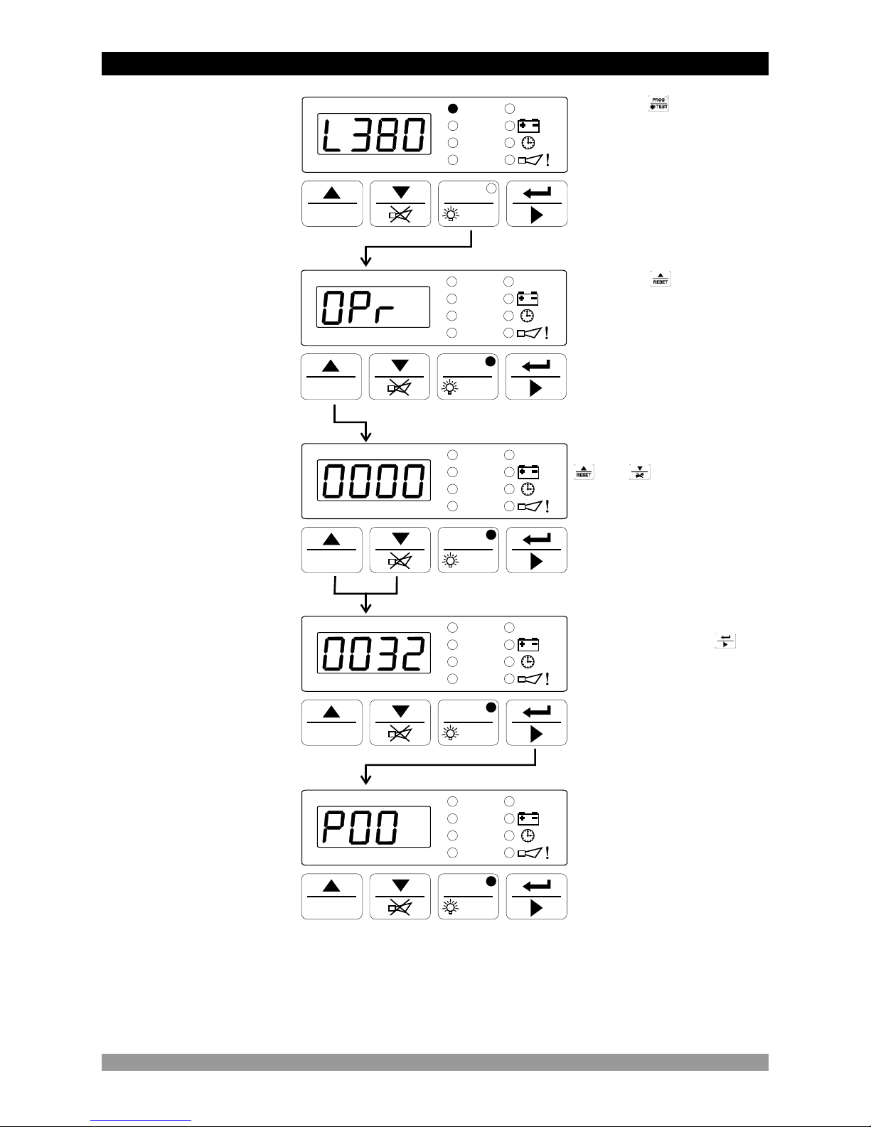
When button is
pressed, all leds and digits
are energised, because
prog button is also used as
test button. Continue to
press the prog buton for 5
seconds, Operator Menu
Entering screen is shown
and prog led lights on.
V
L31/L3N
V
L23/L2N
V
L12/L1N
UV
Hz./RPM
PROGPROG
RESETRESET TESTTEST
V
L31/L3N
V
L23/L2N
V
L12/L1N
UV
Hz./RPM
PROGPROG
RESETRESET TESTTEST
When button is
pressed, operator
password entering screen
is shown.
V
L31/L3N
V
L23/L2N
V
L12/L1N
UV
Hz./RPM
PROGPROG
RESETRESET TESTTEST
Operator Password
Entering Screen
Operator Password
Entering Screen
Change the password with
and buttons
After entering the
password, push the
button for confirming the
password and accessing to
the first parameters of
operator parameters.
V
L31/L3N
V
L23/L2N
V
L12/L1N
UV
Hz./RPM
PROGPROG
RESETRESET TESTTEST
Operator Menu
Entering Screen
NOTE : If no operation is performed for 20 seconds, the device exits from the
programming mode and turns to the main operation screen.
5.2 Changing and Saving Operator Parameter Value
36
V
L31/L3N
V
L23/L2N
V
L12/L1N
UV
Hz./RPM
PROGPROG
RESETRESET TESTTEST
V
L31/L3N
V
L23/L2N
V
L12/L1N
UV
Hz./RPM
PROGPROG
RESETRESET TESTTEST
V
L31/L3N
V
L23/L2N
V
L12/L1N
UV
Hz./RPM
PROGPROG
RESETRESET TESTTEST
V
L31/L3N
V
L23/L2N
V
L12/L1N
UV
Hz./RPM
PROGPROG
RESETRESET TESTTEST
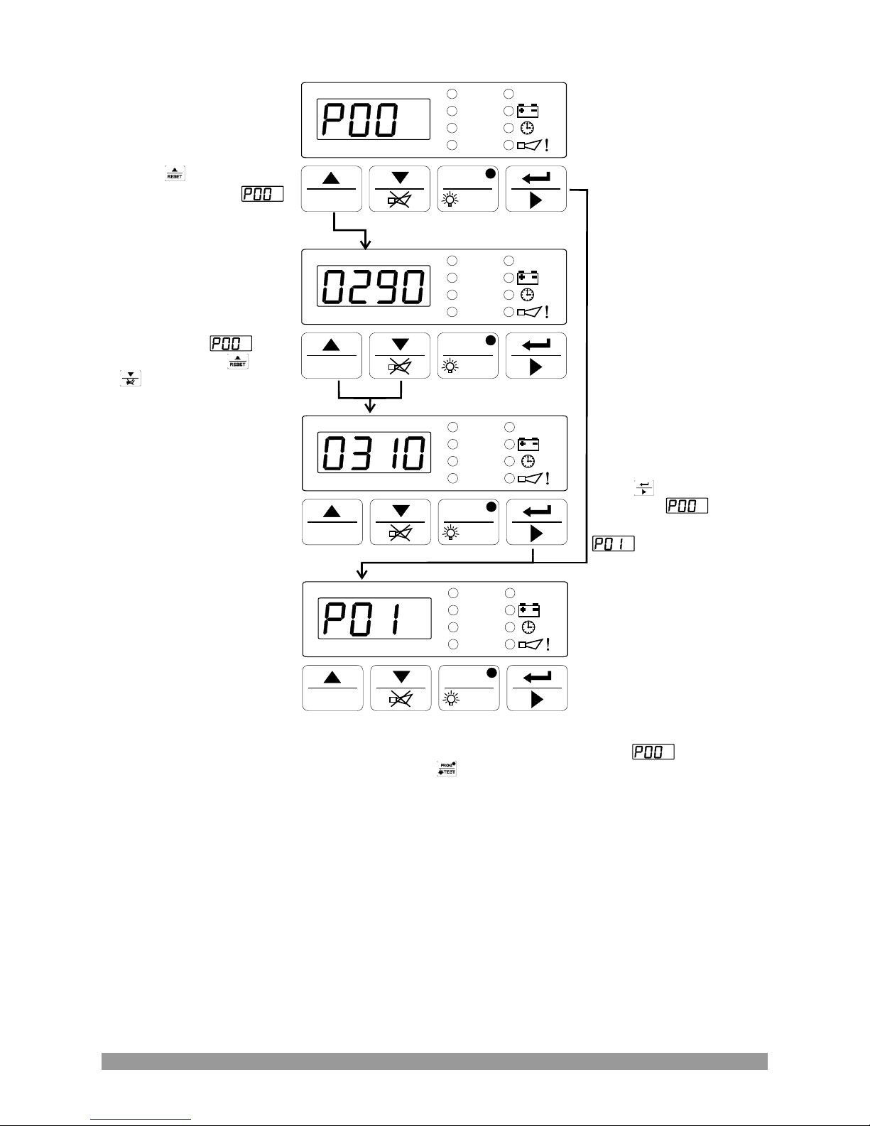
Mains Voltage
Connection Level
Value
Mains Voltage
Connection Level
Value
Mains Voltage
Connection Level
Parameter
Mains Voltage
Disconnection Level
Parameter
Press button for
accessing to the
Value
Press button for
saving the value
and accessing to the
Parameter
Change the
parameter with and
buttons
NOTE : If no operation is performed for 20 seconds, the device exits from the
programming mode and turns to the main operation screen.
NOTE : Other operator paramaters can be accessed as explained for
For exiting from programming mode, press

37
V
L31/L3N
V
L23/L2N
V
L12/L1N
UV
Hz./RPM
PROGPROG
RESETRESET TESTTEST
Operation Screen
When button is
pressed, all leds and digits
are energised, because
prog button is also used as
test button. Continue to
press the prog buton for 5
seconds, Operator Menu
Entering screen is shown
and prog led lights on.
V
L31/L3N
V
L23/L2N
V
L12/L1N
UV
Hz./RPM
PROGPROG
RESETRESET TESTTEST
V
L31/L3N
V
L23/L2N
V
L12/L1N
UV
Hz./RPM
PROGPROG
RESETRESET TESTTEST
When button is pressed
for 10 seconds, technician
menu entering screen is
shown.
V
L31/L3N
V
L23/L2N
V
L12/L1N
UV
Hz./RPM
PROGPROG
RESETRESET TESTTEST
Technician Password
Entering Screen
Change the password with
and buttons
After entering the
password, press the
button for confirming the
password and accessing to
the first parameters of
technician parameters.
Operator Menu
Entering Screen
NOTE : If no operation is performed for 20 seconds, the device exits from the
programming mode and turns to the main operation screen.
V
L31/L3N
V
L23/L2N
V
L12/L1N
UV
Hz./RPM
PROGPROG
RESETRESET TESTTEST
Technician Menu
Entering Screen
When button is
pressed, technician
password entering screen
is shown.
Technician Password
Entering Screen
5.3 Changing and Saving Technician Parameter Value

V
L31/L3N
V
L23/L2N
V
L12/L1N
UV
Hz./RPM
PROGPROG
RESETRESET TESTTEST
V
L31/L3N
V
L23/L2N
V
L12/L1N
UV
Hz./RPM
PROGPROG
RESETRESET TESTTEST
V
L31/L3N
V
L23/L2N
V
L12/L1N
UV
Hz./RPM
PROGPROG
RESETRESET TESTTEST
V
L31/L3N
V
L23/L2N
V
L12/L1N
UV
Hz./RPM
PROGPROG
RESETRESET TESTTEST
Mains Voltage
Connection Level
Value
Mains Voltage
Connection Level
Value
Mains Voltage
Connection Level
Parameter
Mains Voltage
Disconnection Level
Parameter
Press button for
accessing to the
Value
Press button for
saving the value
and accessing to the
Parameter
Change the
parameter with and
buttons
NOTE : If no operation is performed for 20 seconds, the device exits from the
programming mode and turns to the main operation screen.
NOTE : Other technician paramaters can be accessed as explained for
For exiting from programming mode, press
38

39
These commissioning checks may interfere with the power supply to the load. Therefore they
should not be carried out with a mission-critical load connected to the system.
1. Check that the unit is correctly wired and that the wiring is of a standard and rating
compatible with the system.
2. Check that the correct fuses are fitted.
3. Be sure that the parameters are suitable for your system. Please refer to the
Section 5 Parameters for details.
4. Take temporary steps to prevent the engine from starting ( for example, disable the fuel
solenoid ).
5. After a visual inspection to ensure it is safe to proceed, connect the battery supply.
6. On the EAOM-9F / EAOM-9F ND, press the Man (20) button. The associated LED (11)
should light.
7. Press the Engine Start (19) button. The LED (10) should light.
8. Check that the engine start sequence commences. The starter motor should run for the
programmed time period (P28) for the pre-set (P09) number of times.
9. Check that the Start Failure LED flashes and the LED (10) switches off.
10. Check that the unit changes to the OFF mode and the LED (12) should light.
11. Restore the engine to operational state (reconnect the fuel solenoid).
12. Press the Man (20) button. The LED (11) should light.
13. Press the Engine Start (19) button. The LED (10) should light.
14. Check the start sequence, as follows:
The starter motor runs
The engine starts
The starter motor disengages once the engine is running.
If not, check that the engine is fully operational (fuel available etc.) and check the wiring and
programming of the EAOM-9F / EAOM-9F ND.
15. Check that the engine runs up to it’s operating speed. If not and an alarm is present,
check that the alarm is valid and then check the input wiring.
16. Press the Engine Stop (18) button. At this moment the LED (9) should light. The engine
should stop. Allow time for the engine to come to rest.
1. Check that the mains is connected to the unit and is present.
2. Check that the remote inhibit switch (if fitted) is set to disable (contact is open).
3. At the EAOM-9F / EAOM-9F ND, press the Auto (23) button. The LED (14) on the button
should light.
4. Switch off the mains supply to the unit. Check that the generator starts and after a delay,
the load is transferred to the generator
5. Restore the mains supply to the unit. Check that, after a delay, the load is transferred back
to the mains and the generator, after a further delay, shuts down.
6. If a remote inhibit switch is fitted, set it to inhibit (contact is closed)
7. Switch off the mains supply. Check that the generator does not start.
8. Restore the mains supply and set the remote inhibit switch to disable.
c
6. COMMISSIONING
6.1 Manual Operation
6.2. Auto Operation
40
When button is pressed, all leds and digits are energised.
1. Check that the mains is connected to the unit.
2. Press the Test (22) button. The LED (13) should light.
3. Check that the generator starts and that the load is still connected to the mains.
4. Switch off the mains supply. Check that the contactors change over to connect the load to
the generator. Check also that the Auto (14) LED is lit. The unit changes operating mode to
AUTO Mode automatically.
5. Restore the mains supply. Check that the contactors reconnect the load to the mains
supply.
6. Check that the generator shuts down with Engine Cooling Time (P10)
6.3 Test Mode Operation
7. LAMP TEST

Number
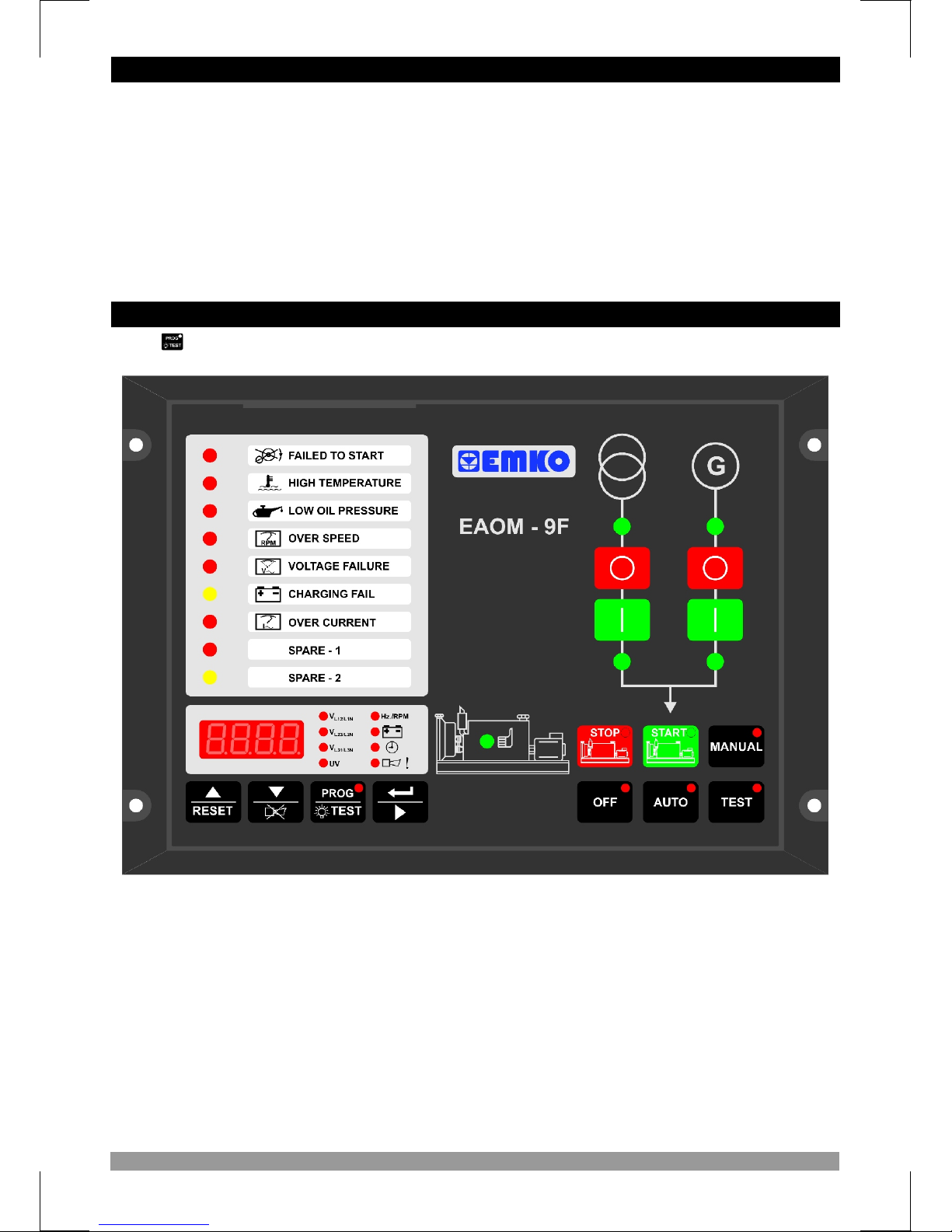
The green LED indicates that the engine has started and is running.
2626
2525
1616 1717 1515 2424
88
33
1818
1919
2020
222223232121
1212
1414
1313
99 1010 1111
66
77
55
22
2828
11
2727
44
Comment
1
2
3
The LED indicates that the load is connected to the mains.
The LED shows that the load is supplied from the generator.
The red LED illuminates only when EAOM-9F / -9F ND is in programming mode.
5
4
6
7
8
9
10
11
This red LED shows that the unit is in the Manual mode.
This red LED shows that the unit is in OFF mode.
This red LED shows that the Unit is in TEST mode.
12
13
This red LED shows that the Unit is in the AUTO mode.
14
15
16
17
41
18
19
8. OPERATION
8.1 Front Panel Description
The Stop button is used for stopping the engine when the unit is in the
Manual mode.
Prog/Lamp Test.. Lights all the LEDs and segments on the panel so that you
can see if any are not working. Holding the button pressed for five seconds puts
the unit into Programming mode and LED (8) illuminates
This button opens the mains contactor only operative when manual mode is
selected
Multi Function Display. This is used for displaying the electrical measurements
during normal operation and editing / inspecting programming parameters in
programming mode.
The Display Scroll Button is used for rotating between measurement screen in
normal operation and between programming parameters in programming mode.
The AUTO button is used for changing operating mode of the unit to the Auto mode
The TEST button is used for changing operating mode of the unit to the Test mode
The MAN button is used for changing operating mode of the unit to the Manual mode
The OFF button is used for changing operating mode of the unit to the Off mode
Number Comment
20
21
22
23
24
25
Failure Indicators. Detailed information available in Section 9
26
27
28
V
L31/L3N
V
L23/L2N
V
L12/L1N
UV
Hz./RPM
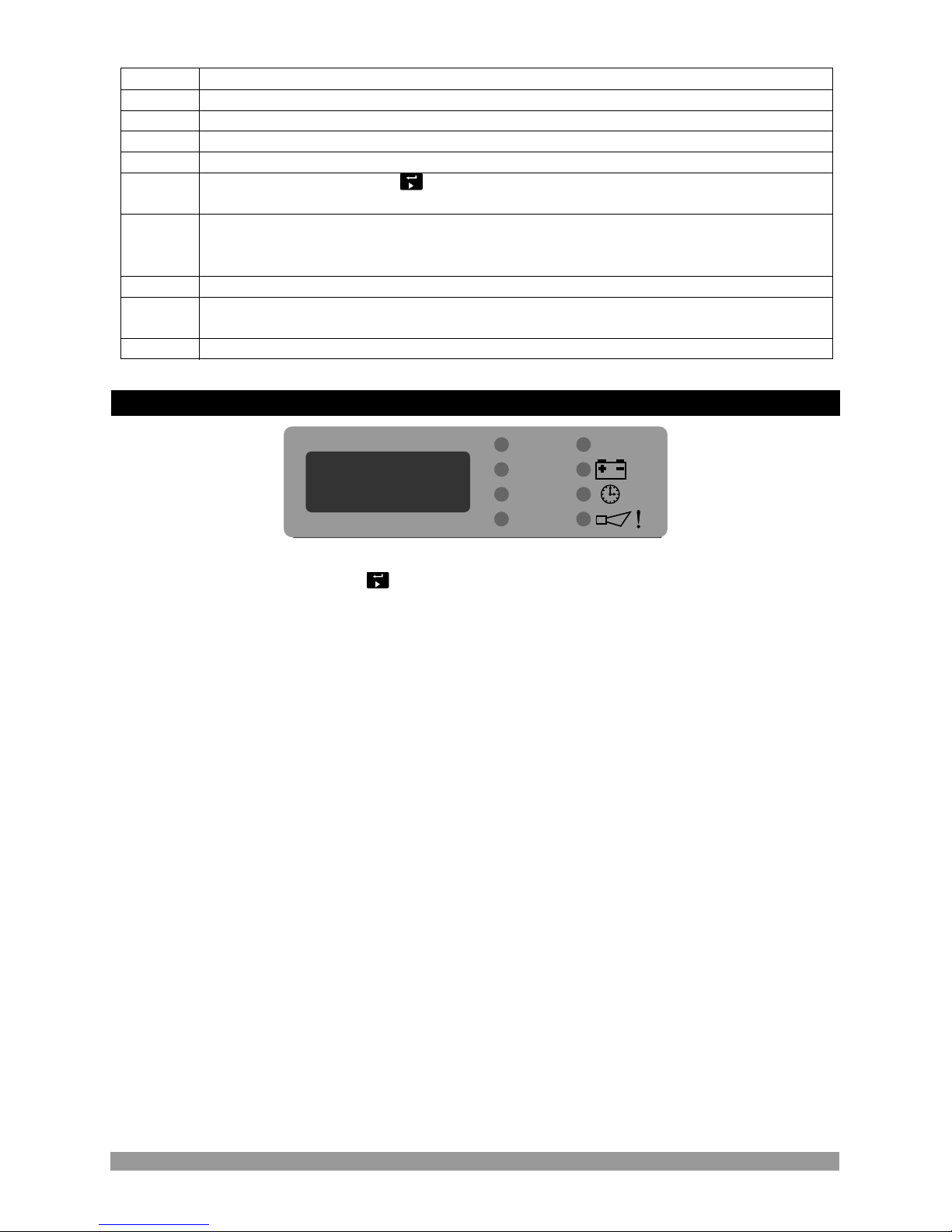
Four-digit, seven-segment LED display, with annunciators to indicate the parameter being
displayed. Use the scroll button to select the desired parameter. The button selects the
parameters in sequence, as follows. Note that line to line voltage readings are prefixed by L while
line to neutral readings are prefixed by n
• Mains voltage L1-L2, prefix L
• Mains voltage L1-N, prefix n
• Mains voltage L2-L3, prefix L
• Mains voltage L2-N, prefix n
• Mains voltage L3-L1, prefix L
• Mains voltage L3-N, prefix n
• UV - Alternator voltage L1
• Frequency (Hz)
• Battery voltage ( VZ)
• Timers
Engine running time, in hours (since last reset). This is a six digit number, the first three digits are
prefixed H (high) and the second three digits are prefixed L (low).
Automatic exercise timer. Elapsed waiting time (hours) to the next exercise is prefixed E The
exercise running time (minutes) is prefixed r
• The Alarm horn LED will flash continually if the unit detects at least one of the faults listed below.
When the Display Select button is pressed so as to select this option, the display will show the
cause of the fault indication. If more than one error condition is present, repeated pressing of the
button will show each in turn.
Possible error messages are:
EStP – Emergency S t op
bAT1 – Low Battery Voltage Alarm
Serv – Routine Maintenance due info
8.2 Display Mode Indicators
This button opens the alternator contactor only when manual mode is selected
42

The mode can be changed at any time. A change in mode will not effect the current state of the
generator or load connection. For example; if the unit is in Auto mode with the generator running
and the load running on the generator, changing the mode to Manual will not effect the operating
state. Any changes between Auto, Manual and Test modes will not change the operating state.
43
8.3 Mode Transition
1. Press the Man (20) button. The LED (11) will switch on.
2. Press the Engine Start (19) button on the panel. The LED (10) will switch on. The engine
should start. The sequence is as follows:
! The starter motor runs
! The engine starts
Once the engine is running,
! The LED (3) “Engine Running” illuminates.
! The “Alternator Ready” LED (2) switches on after “Control on Delay (P30)” time period.
! The generator will not supply the load unless the “Generator Ready” LED (2) is illuminated
(The contactor open / close button does not work)
3. Once both LEDs have illuminated, press the Mains Contactor Button (27) to disconnect the
load from the mains supply LED (6) should go off.
4. Press the Generator Contactor Button (5) to connect the load to the generator supply. LED
(7) should light.
When the “Engine Stop” (18) button is pressed, the LED (9) is illuminated and engine is stopped
When the “Engine Stop” button is pressed while the load is connected to the alternator output
(generator output), the alternator contactor is released then the engine is stopped.
Press the Auto (23) button to select Auto mode. The LED (14) in the corner of the button will light
to indicate this mode has been selected.
In the event of a mains voltage failure, the unit will start up the generator and, once the generator
is running and generator is available to take the load, will transfer the load to the generator. When
the mains is restored and stable, it will transfer the load back to the mains and, after Engine
Cooling Time (P10) shut down the generator.
Note that if 0 VZ in Remote Inhibit (Pin19), it will inhibit engine running.
Press the Test (22) button to select Test mode. The LED (13) will switch on. This mode allows for
testing of the generator off load. All alarm circuits will operate so that any faults will be reported. If
a mains failure occurs while the unit is in Test mode, the unit will revert to Auto mode and will
switch the load to the generator.
8.4 Manual Start
8.5 Manual Stop
8.6 Auto Operation
8.7 Test Operation
The unit incorporates facilities for exercising the engine on a regular basis. If the unit is in Auto
mode, after an interval (hours) determined by Exercise Time (P14), the unit will go into Test mode
and start up the engine. The system will run in Test mode, without transferring the load to the
alternator, for the period (minutes) determined by Exercise Duration Time Period (P15). At the
end of this period, the unit will revert to Auto mode, shut down the engine and reset the exercise
interval timer. If the unit is not in Auto mode at that time, the unit will restart the exercise interval
timer without having exercised the engine. If the mains fails while the engine is being exercised,
the unit will revert to Auto mode and transfer the load to the alternator. If the user changes the
mode, the engine exercise will be abandoned and the unit will respond according to the mode
selected and the current state of the mains supply.
8.8 Engine Exercising

Indicators on the central section of the panel will flash if a fault is detected. Fault conditions latch
so that further operation is prevented. If a failure is indicated, proceed as follows:
1. Change the unit in to MAN mode and stop the generator
2. Find and fix the fault.
3. Press the Failure Reset (16) button to enable a restart.
4. Select the required mode of operation – Manual, Auto or Test.
This LED flashes if the engine has not started after the programmed Number of Starting Attempts
(P09). The unit must be reset, by pressing the Failure Reset (16) button, before a fresh attempt
can be made.
This LED flashes if the thermostatic switch on the engine indicates high temperature. If this fault
occurs, the EAOM-9F will stop the engine without any Engine Cooling Time (P10).
This LED flashes if the Oil Pressure Switch on the engine indicates low oil pressure while the
engine is running. To obtain this indication, the engine must have been running for at least the
period specified by the Oil Pressure By-Pass Time (P31). If this fault occurs, the EAOM-9F will
stop the engine without any Engine Cooling Period (P10).
This failure is indicated if the generator runs for Control On Delay (P32) time. This LED flashes if
the field current for the battery charge generator fails to fall to zero after the engine has started.
This failure will not stop the generating set.
This failure is indicated if the generator runs for Control On Delay (P32) time. This LED flashes if
the alternator speed goes above the Speed Upper Limit (P05). For a fault to be indicated, the
speed must be over this limit for longer than the period defined by the Speed Fault Control Delay
(P34).
Alternator speed is measured either by measuring alternator output frequency or by monitoring
an external magnetic pick-up, as selected by Speed Sensing Input Selection (P18).
This failure immediately stops the generating set, without any Engine Cooling Time (P10) period.
This failure is indicated if the generator runs for Control On Delay (P32) time. This LED flashes if
the alternator output voltage is outside of the limits programmed into Alternator Voltage Lower
Limit (P03), and Alternator Voltage Upper Limit (P04), for a time period longer than the Alternator
Voltage Fault Control Delay (P33). This failure immediately releases the generator contactor, and
stops the generating set without any Engine Cooling Time (P10) period.
44
9. FAULT FINDING
9.1 Fault indications
9.1.1 Failed to Start LED
9.1.2 High Temperature LED
9.1.3 Low Oil Pressure LED
9.1.4 Charge Generator Failure LED
9.1.5 Over Speed LED
9.1.6 Generator Voltage Failure LED

The remote Emergency Stop button has been pressed and has shut down the engine. After fixing
the fault press Failure Reset (16) to remove the indication and restore EAOM-9F operation. This
failure is indicated with Led in EAOM-9F ND and as error messages in EAOM-9F. When this
failure occurs in EAOM-9F the led with exclamation mark starts to flash and user can see the error
messages with the Scroll button .
The LED switches on when the battery voltage falls below the value specified by the Battery
Voltage Lower Limit (P21) EAOM-9F measures battery voltage at the EAOM-9F terminals.
This failure is indicated with Led in EAOM-9F ND and as error messages in EAOM-9F. When this
failure occurs in EAOM-9F, the led with exclamation mark starts to flash and user can see the
error messages with the Scroll button .
The interval (hours run) between routine maintenance, set by Periodic Maintenance Hour Set
Value (P07), has expired. On completion of the required engine maintenance, reset the
maintenance timer using Periodic Maintenance Hour Reset (P08). This failure is indicated with
Led in EAOM-9F ND and as error messages in EAOM-9F. When this failure occurs in EAOM-9F,
the led with exclamation mark starts to flash and user can see the error messages with the Scroll
button . This failure is not stopped the generating set. If the failure is cleared with the reset
button, hours run is cleared by the EAOM-9F.
If the inputs are configured to be controlled after the engine starts to run. This failure is indicated if
the generator runs for Control On Delay (P32) time.These LEDs indicate the status of the
Configurable Input-1 (Pins 18) and Configurable Input-2 (Pin 17), and the controller can be
programmed to perform various functions when these inputs become active.
45
This failure is indicated if the generator runs for Control On Delay (P32) time. The unit monitors an
external Over Current relay (Pin 21) when the Generator is running and the Load is on the
Generator. If the input becomes active at any time,this LED flashes and the generator contactor is
released, but the engine continues to run.
9.1.7 Over Current LED
9.1.8 Configurable Input-1 and 2 LED
9.1.9 EAOM-9FEmergency Stop Message LED ( ND only)
9.1.10 EAOM-9FLow Battery Voltage Message LED ( ND only)
9.1.11 EAOM-9FMaintenance Time Message LED ( ND only)

Symptom
Check all the wiring of the unit.
Check the Z supply. (measure voltage between pins 14 and 13)
Check the Z fuse.
Check engine oil level and pressure.
Check oil pressure switch and wiring.
Check engine temperature and cooling systems.
Check switch and wiring.
Check fuel solenoid and wiring, fuel and battery.
Reset the EAOM-9F and restart the engine.
Check solenoid transistor output activated,
(Fuel Solenoid if selected)
Check the signals that the EAOM-9F is using to determine if the
engine has started. Refer to the engine manual.
Check wiring to starter solenoid.
Check battery supply.
Check battery supply is present on the Start output (Pin12) of the
EAOM-9F.
Low oil pressure fault
after engine has
Unit is inoperative.
High engine
Temperature.Fault after
Failed to Start fault.
Engine failed to Start
Starter motor
Isolate the equipment from the electricity supply during mechanical and
electrical maintenance. When this is not possible, the equipment must be in
the “OFF” position.
c
after Pre-set Number
Started.
engine has started.
Of Attempts.
Inoperative.
Possible Remedy
46
P18
P12
No
P02
P03
P04
P05
P06
P07
P09
P13
P14
P16
P17
0=Alternator
Pick-up
P19
P20
P21
P22
P23
P24
P25
Engine started signal
P26.0
P26
P26.2
P26.3
0=No, 1=Yes
P15
P10
P28
Alternator voltage limit for crank disconnection
P30
P31
P32
P33
P34
Enter technician password
P36
P29
P35
P00
P01
600
60
60
60
60
600
600
600
600
30.0 75.0
90 365
0000 9999
VV
VV
VV
VV
VV
60
Hz
Day
Hour
1 10
Number
0 99
Minute
0 999
Second
0 30
Minute
0 99
Second
0 999
Hour
0 999
Minute
500 5000
Rpm
1 1000
Number
7.2 24.0
VZ
0.1 25.0
Second
0 99
Second
5
99
Second
40 360
VV
20.0 45.0
Hz
0 99
Second
0 99
Second
0.0 10.0
Second
0.0 10.0
Second
0/1
0/1
0/1
0/1
Charge Generator
Speed
Alternator Voltage
Oil Pressure
P26.1
50.0/60.0
Hz
1/3
Stop / Fuel
0=Off,1=Auto
Number
Normal / Fail safe configuration of inputs
P37 310
Number
Min
User Def.Value
Unit
Definition of Parameter
Max
Mains Voltage Connection Level
Mains Voltage Disconnection Level
Mains Voltage Upper Limit
Alternator Voltage Lower Limit
Alternator Voltage Upper Limit
Speed Upper Limit
Periodic Maintenance Day Set Value
Periodic Maintenance Hour Set Value
Press ‘Silence Alarm’ button
Number of Starting Attempts
Engine Cooling Time(0 disable cool process)
Horn Duration (0 Continuous)
Mains Transition Delay
Preheat Time
Exercise Time (0 Disable)
Exercise Duration Time Period
Single / Three Phase Selection
Speed Sensing Input Selection
Nominal Alternator Frequency
Nominal Speed
Tooth Number
Battery Voltage Lower Limit
Mains Change Over Delay
Stop / Fuel Solenoid Selection
Stop Magnet Energising Time
Starting Attempt Duration
Speed Limit for Crank Disconnection
Oil Pressure By-Pass Time
Control on Delay
Alternator Voltage Fault Control Delay
Speed Fault Control Delay
Engine running time reset
“Power ON” default mode configuration
1 = Magnetic
(Internal)
Signal
to reset time to “0” (zero)
to reset
P08
Periodic Maintenance Hour Reset
10. PROGRAMMABLE PARAMETERS
P11
0=None, 1=Exists
Horn Blink Selection
0.0 25.0
Second
P27
47
Engine Starting Delay

No
P42 13
Number
0
Min
User Def.Value
Unit
Definition of Parameter
Max
Configurable Output
P43
Mains Contactor Selection
Operator Password (P00...P15 and P47)
Technician Password (P00...P48)
0000 9990
0000 9990
Number
Number
Number
P47
P48
48
0=Mains contactor
is NO
1=Mains contactor
is NC
Configurable input-1 operation
P38
Configurable input-2 operation
P39
P40
P41
0 10
Number
0 10
Number
0 10
Second
0 10
Second
Configurable input-1 delay time
Configurable input-2 delay time
P44
Motor Fuel (Gas/Diesel) Selection
P45
0.0 25.0
Fuel-Starter (Diesel)/Starter-Fuel (Gas)
P46
0 2
Remote Control Mode Selection
0=Gas
1=Diesel
0 Prevent running
1 Run without load
2 Run with load
Delay Time

Equipment Use : Electrical control equipment for generating sets
Housing& Mounting : 144 mm x 204 mm x 37 mm (including connectors) plastic
housing for panel mounting
Panel Cut-Out : 138 mm x 186 mm
Protection : NEMA 4X (IP65 at front panel, IP20 at rear side).
Weight : Approximately 0.45 Kg.
Environmental Ratings : Standard, indoor at an altitude of less than 2000 meters with
non-condensing humidity.
oooo
Operating/Storage Temperature : -25 C to +70 C / -40 C to +85 C
Installation Overvoltage Category : II Appliances, portable equipment
Pollution Degree : II, normal office or workplace, none conductive pollution
Mode of Operation : Continuous
EMC : EN-61000-6-4, EMC generic emission standard for industrial
equipment
EN-61000-6-2, EMC generic immunity standard for industrial
equipment
Electrical Safety : EN-61010-1, safety requirements for electrical equipment for
measurement, control and laboratory use
Supply Voltage : 8-32 VZ
Supply Voltage Measurement : 8-32 VZ. Accuracy : 1%, Resolution : 0.1VZ
Mains Voltage Measurement : Three phase, 4 wire 35 to 300 VL-N V Accuracy : 1%FS,
Resolution : 1VV
Generator Voltage Measurement : Single phase, 2 wire 35 to 300 VL-N V Accuracy : 1%FS,
Resolution : 1VV
Measurement Accuracy : 1% of the range
Cranking Dropouts : Battery voltage can be 0 VZ for max. 100msec during cranking
(battery voltage should be at least nominal voltage before
cranking)
Generator Speed Measurement : From alternator or magnetic pickup
Alternator Frequency Range :10-110 Hz. (@35-300 VL-NZ)
Magnetic Pickup Freq. Range : 3 5 Hz - 10 kHz (@3-35 Volts peak)
Charge Generator Excitation :12 VZ or 24 VZ, 200 mA, max 3W
Communication Interface : RS-232 serial communication
Contact Sensing Input : Emergency stop (NC), Oil pressure switch, Temperature switch,
Remote inhibit input (NO), Configurable input 1, Configurable input 2,
Over current input
Outputs : Start, Fuel, Horn, Configurable Output, Mains Contactor Output,
Generator Contactor Output(All outputs are 500mA Transistor Output)
Display (4-digit, 7-segment LED display) : Mains L1 – L2 Voltage, Mains L1 – N Voltage, Mains L2 – L3
Voltage, Mains L2 – N Voltage, Mains L3 – L1 Voltage, Mains L3 – N
Voltage, Alternator Voltage, Alternator Frequency, Engine Speed,
Battery voltage, Engine running time, Error indication, Program
Parameters (Only EAOM-9F)
Failure Indicators : Failed to start, High temperature, Low oil pressure, Over speed,
Generator voltage failure, Charge failure, Over current, Configurable
input 1, Configurable input 2, Low battery voltage (observed with led
in EAOM-9F ND, failure message in EAOM-9F), Maintenance due
(observed with led in EAOM-9F ND, failure message in EAOM-9F)
Emergency stop (observed with led in EAOM-9F ND, failure message
in EAOM-9F)
Status Indicators :Off mode, Auto mode, Test mode, Manual mode, Engine start,
Engine stop, Engine running, Mains voltage available, Generator is
ready to take the load, Mains contactor, Generator contactor
Information Alarms : Low battery voltage (EAOM-9F), Maintenance due (EAOM-9F),
Emergency stop (EAOM-9F)
Approvals : GOST-R,
49
11. SPECIFICATIONS
 Loading...