

Page 1
DETECTEURS DE POSITION
pour rainures profi l "T"
FR
CARACTERISTIQUES GENERALES DU DETECTEUR
PUISSANCES COMMUTABLES maxi CC = 5 W - CA = 5 VA
TENSION COMMUTEE voir ci-dessous
INTENSITE COMMUTEE max. 100 mA
PROTECTION COURT CIRCUIT non
PROTECTION POLARITE oui (sans fonction LED)
PROTECTION SURTENSION non
CHUTE DE TENSION (EN 60947-5-2) < 5 volts
TENSION DE CLAQUAGE 230 V CC
RESISTANCE DES LAMES 0,2 ohm max.
RESISTANCE D’ISOLEMENT 10
SENSIBILITE 2,1 mTesla (21 Gauss)
TEMPS DE REPONSE 0,1 ms à l’ouverture - 0,6 ms à la fermeture
PRECISION DE REPETITIVITE < ± 0,2 mm
TEMPERATURE D’UTILISATION - 25°C , + 70°C
ENVELOPPE
CABLE PUR, résistant aux huiles de coupe
DEGRE DE PROTECTION (CEI 60529) IP 67
CLASSE DE PROTECTION sortie de fi ls classe II, connexions M8 et M12 classe III
CERTIFICATION CE
SIGNALISATION par diode (LED) jaune qui s’allume lorsque le contact est fermé
à ampoule (ILS)
8
ohms à 100 Volt
surmoulage thermoplastique PA + FV
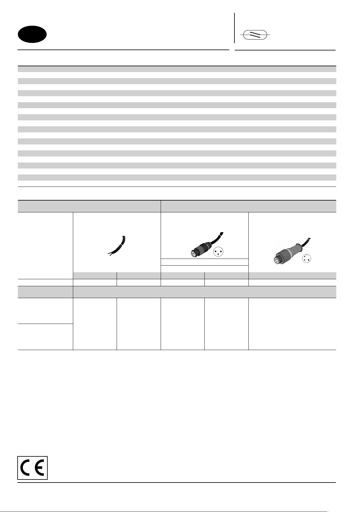
Série
REED
Type
2 fi ls
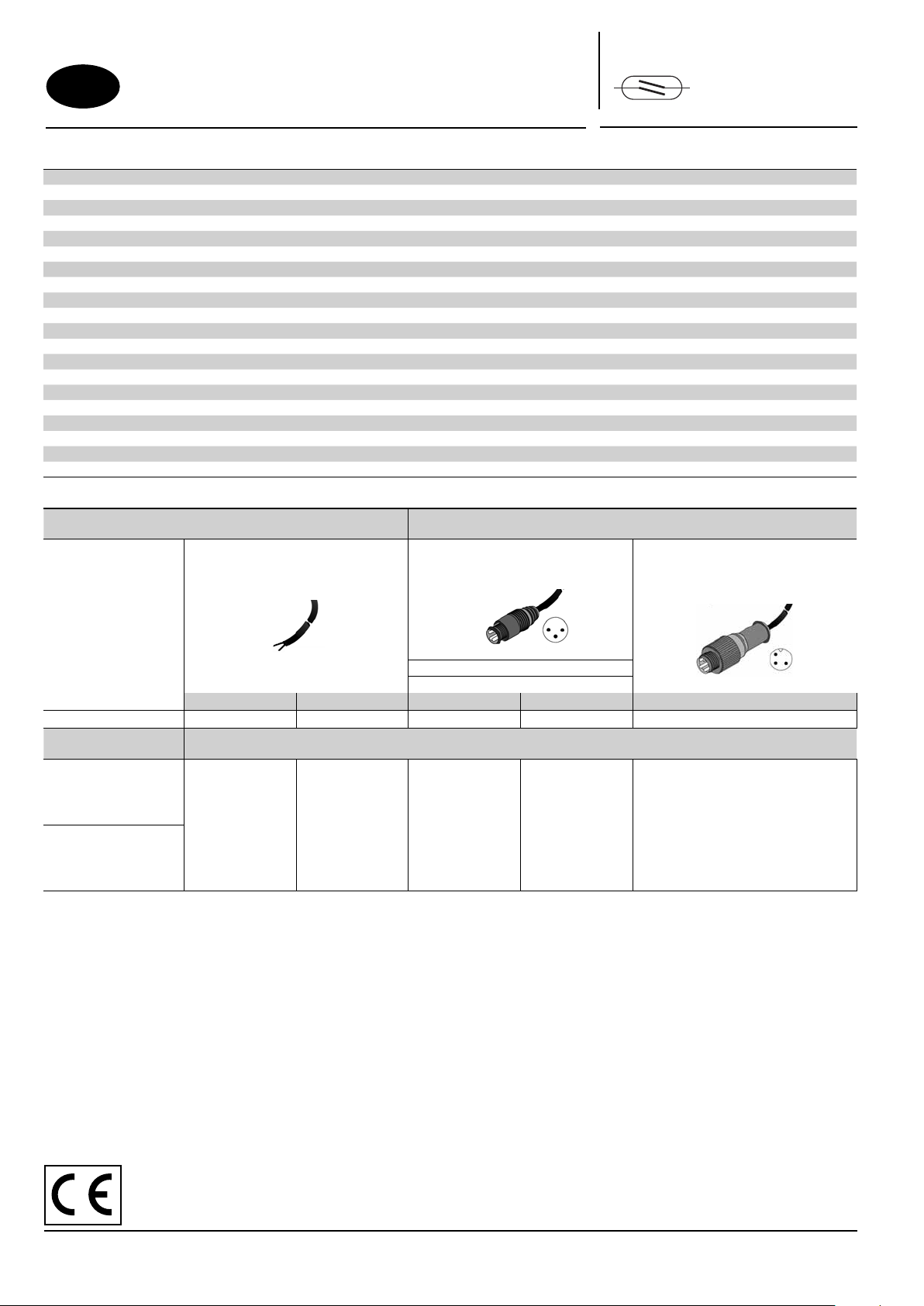
CHOIX DU DETECTEUR
Tension
Raccordement
Masse (g) 22 50 7 7 16
Adaptable sur
vérins type:
PEC
PES 453
PES Ω (453)
CSC - CGT
ISOCLAIR (2)
K - P2B - P2L
PES 450 - PES Ω (450)
PCN
(1) Détecteur permettant l’adaptation directe sur vérins à rainures "T"
(2) Nécessite un kit de fi xation, voir pages 7 et 8
(3) Marché U.S.
(1)
5 à 120 Volt CA/CC
câble PUR 2 ou 5 m
2 conducteurs 0,14 mm
extrémité dénudée
2 mètres 5 mètres 0,3 mètre 0,3 mètre 0,3 mètre
REED-FL2-00 REED-FL5-00 REED-QDS-M8E
2
détecteur livré avec clip de maintien de câble et butée de position de réglage
+ connecteur mâle encliquetable et Ø M8
CODE STANDARD détecteur
câble PUR 0,3 m
3 broches
connexion des broches
1 - 4 1 - 3
REED-QDS-M8U
5 à 50 Volt CA
5 à 60 Volt CC
(3)
câble PUR 0,3 m
+ connecteur mâle à vis Ø M12
3 broches
REED-QDS-M12E
ACCESSOIRES ET AUTRES CARACTERISTIQUES ELECTRIQUES : voir page suivante
Conformément à la directive CEE 98/37/CE Annexe II B, une Déclaration d’incorporation peut être fournie sur demande.
Veuillez nous indiquer le numéro d’accusé de réception (AR) et les références ou codes des produits concernés.
Ce produit est conforme aux exigences essentielles de la Directive 89/336/CEE sur la Compatibilité Electromagnétique, et
amendements. Une déclaration de conformité peut être fournie sur simple demande.
(3834935) MS-P291-1
Page 2
CARACTERISTIQUES ELECTRIQUES MAXIMALES ET PROTECTION DU DETECTEUR MAGNETIQUE (ILS)
5 m
br = 1
blk= 4
blu= 3
143
PVC
5 m
br = 1
blk= 4
blu= 3
1
4
3
2
PVC
1
3
4
CM5
Intensité commutée maxi: 100 mA
Les détecteurs utilisés avec charge inductive (électrovannes, relais,…) nécessitent une protection (diode de roue libre, diode transil,
varistor,…) pour éviter la dégradation des contacts par des surtensions.
CAS PARTICULIERS (valables pour tous les modèles)
• Détecteurs utilisés en commande directe d’ampoules à incandescence : la puissance indiquée sur l’ampoule tient compte de la résistance lorsque
celle-ci est chaude. Lors de la mise sous tension, ampoule froide, la résistance étant très faible, l’intensité devient très importante et peut dépasser
les performances de l’ILS. Il convient donc de tenir compte de la puissance réelle de l’ampoule à l’état froid.
•
Longueurs de câbles supérieures à 10 m: prévoir en plus une résistance de 200 Ω à placer en série au plus proche du détecteur afi n de réduire
les effets capacitifs dus à la ligne.
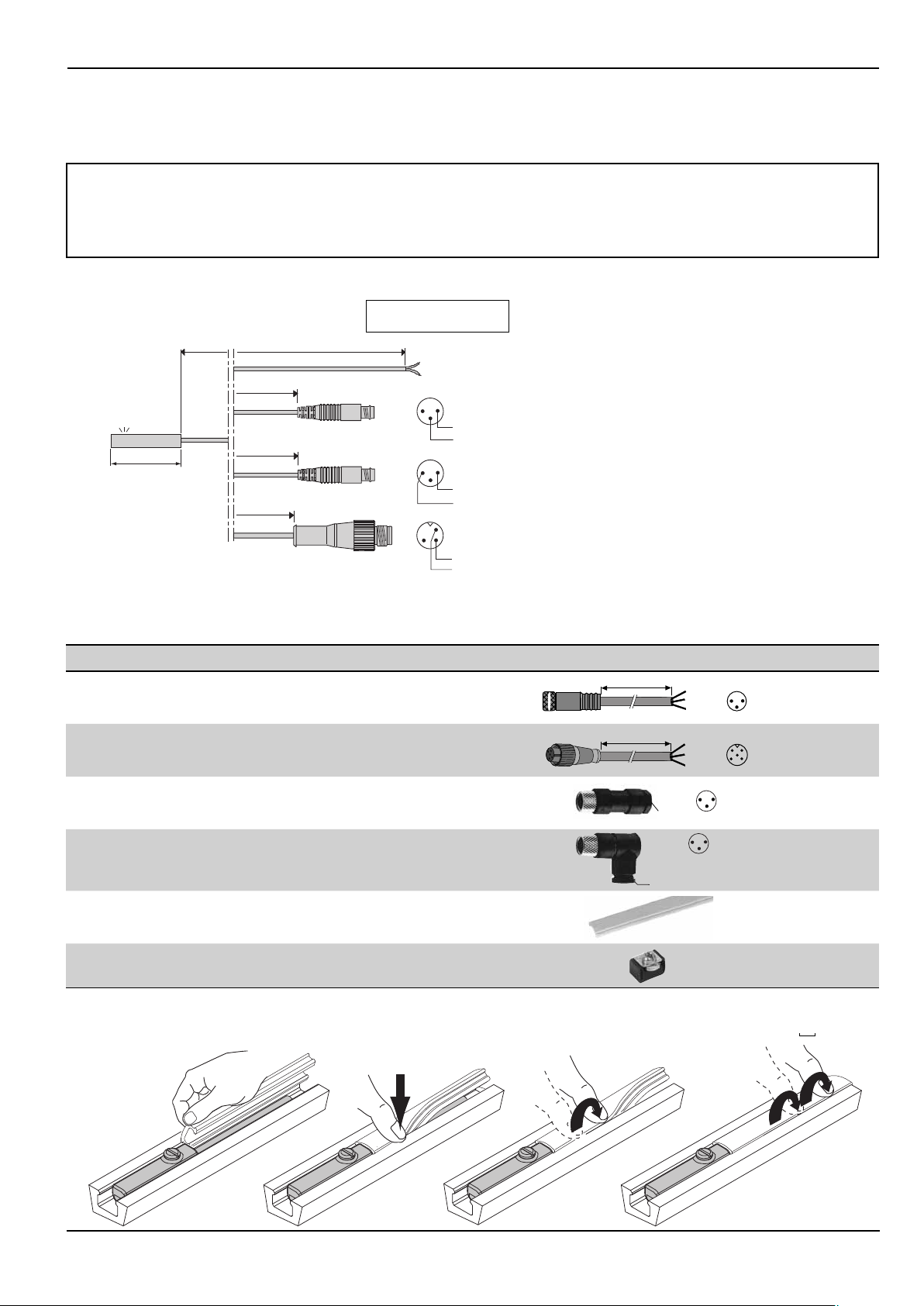
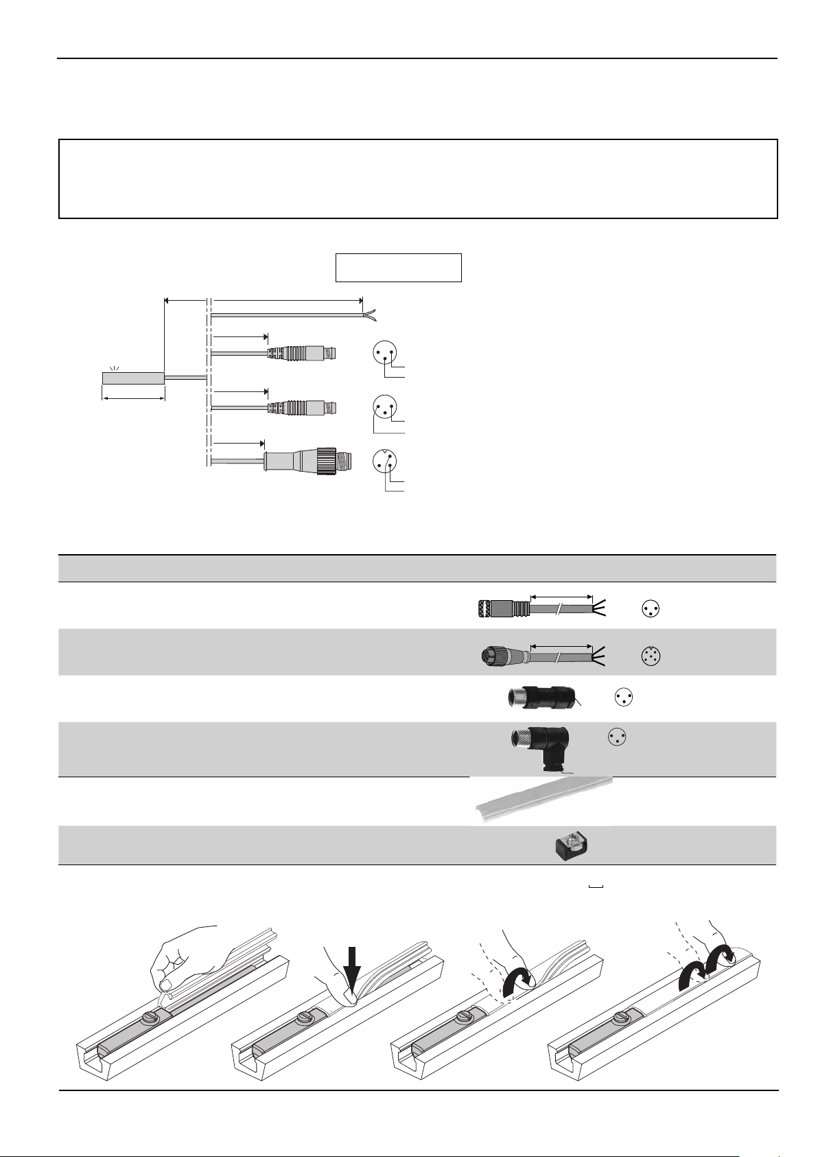
CONNEXIONS DES DETECTEURS A AMPOULE (ILS) : 4 possibilités
Vue côté des broches
des connecteurs mâles
30 mm
2 / 5 m
0,3 m
3
4
0,3 m
3
4
0,3 m
3
Sortie par câble PUR Ø 3 mm, extrémité dénudée
2 conducteurs 0,14 mm
2
- fi l marron = +
fi l bleu = -
Sortie par câble PUR Ø 3 mm avec connecteur mâle
1
encliquetable + à vis Ø M8 - 3 broches (2 broches utiles, 1 et 4)
Sortie par câble PUR Ø 3 mm avec connecteur mâle
1
encliquetable + à vis Ø M8 - 3 broches (2 broches utiles, 1 et 3)
1
4
Sortie par câble PUR Ø 3 mm résistant aux liquides de coupe avec
connecteur mâle à vis Ø M12 - 3 broches (2 broches utiles, 1 et 4)
Recommandation de montage :
S'assurer que le câble électrique d'alimentation du détecteur n'est pas soumis à des tractions / torsions néfastes à sa durée de vie
ACCESSOIRES
désignation
allonge par câble en PVC, longueur 5 m, 3 conducteurs 0,25 mm2 avec 1
connecteur M8 femelle vissable (l’autre extrémité nue), IP67
allonge par câble en PVC, longueur 5 m, 3 conducteurs 0,25 mm
avec 1 connecteur M12 femelle vissable (l’autre extrémité nue)
2
, IP67
connecteur droit Ø M8, 3 broches femelles, IP67
3
connecteur coudé à 90° Ø M8, orientable 90° x 90°,
3 broches femelles, IP67
1
4
CM5
réglette de protection des rainures et maintien des câbles
(vendue par multiple de 1 m - longueur mini = 1 m
Bloc de mémorisation de la position de réglage du détecteur
(1) Pour votre commande, nous préciser - code: 88100746 complété de la longueur (en mètre) souhaitée - exemple: 2 m = 88100746 2
code
88100239
88100238
88100202
88100203
88100746
N199-1162
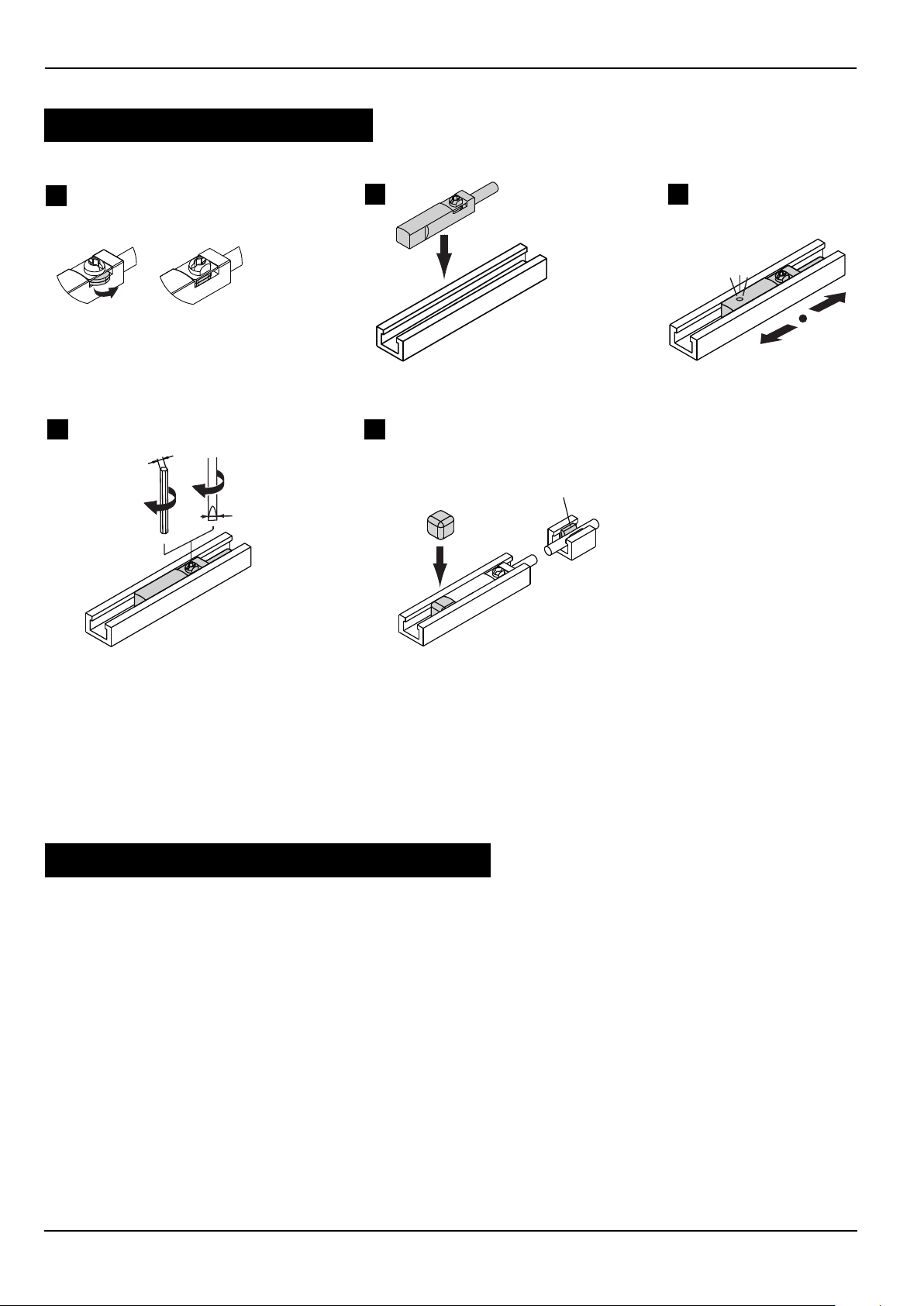
MONTAGE DE LA REGLETTE DE PROTECTION ET MAINTIEN DES CABLES
(1)
2
Page 3
DETECTEURS DE POSITION
pour rainures profi l "T"
magnéto-résistif (MR)
CARACTERISTIQUES GENERALES DU DETECTEUR
PUISSANCES COMMUTABLES maxi 3 W
TENSION COMMUTEE 10 à 30 VCC
INTENSITE COMMUTEE 100 mA
BRANCHEMENT PNP - NPN (3)
PROTECTION POLARITE oui
PROTECTION SURTENSION oui
PROTECTION COURTS CIRCUITS oui
CHUTE DE TENSION (EN 60.947-5-2) < 1,5 volt (I = 50 mA)
COURANT DE FUITE maxi < 50 µA
SURTENSION ADMISSIBLE 32 VCC maxi (100 ms)
SENSIBILITE 2 mTesla (20 Gauss)
TEMPS DE REPONSE 110 µs à l’ouverture - 220 µs à la fermeture
PRECISION DE REPETITIVITE < 0,2 mm
TEMPERATURE D’UTILISATION - 25°C , + 85°C
ENVELOPPE
CABLE PUR, résistant aux huiles de coupe (PVC pour la version M12 IP69K)
DEGRE DE PROTECTION (CEI 60529) IP67 / IP69K
CLASSE DE PROTECTION classe III
SIGNALISATION
CERTIFICATION CE - UL et cUL pour connexions 2 m et M8
Par diode (LED) jaune qui s’allume lorsque la commutation est réalisée
< 2,5 volts (I = 100 mA)
surmoulage thermoplastique PA + FV
PNP-NPN
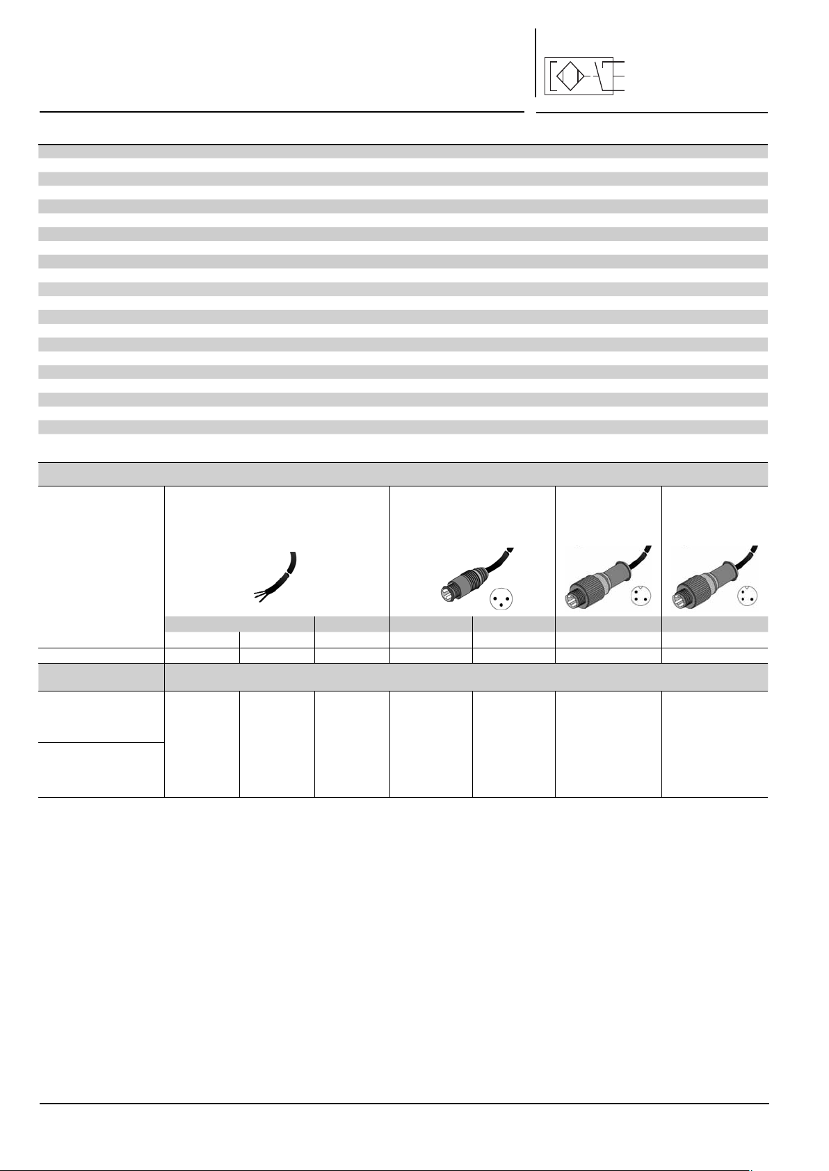
Série
Type
3 fi ls
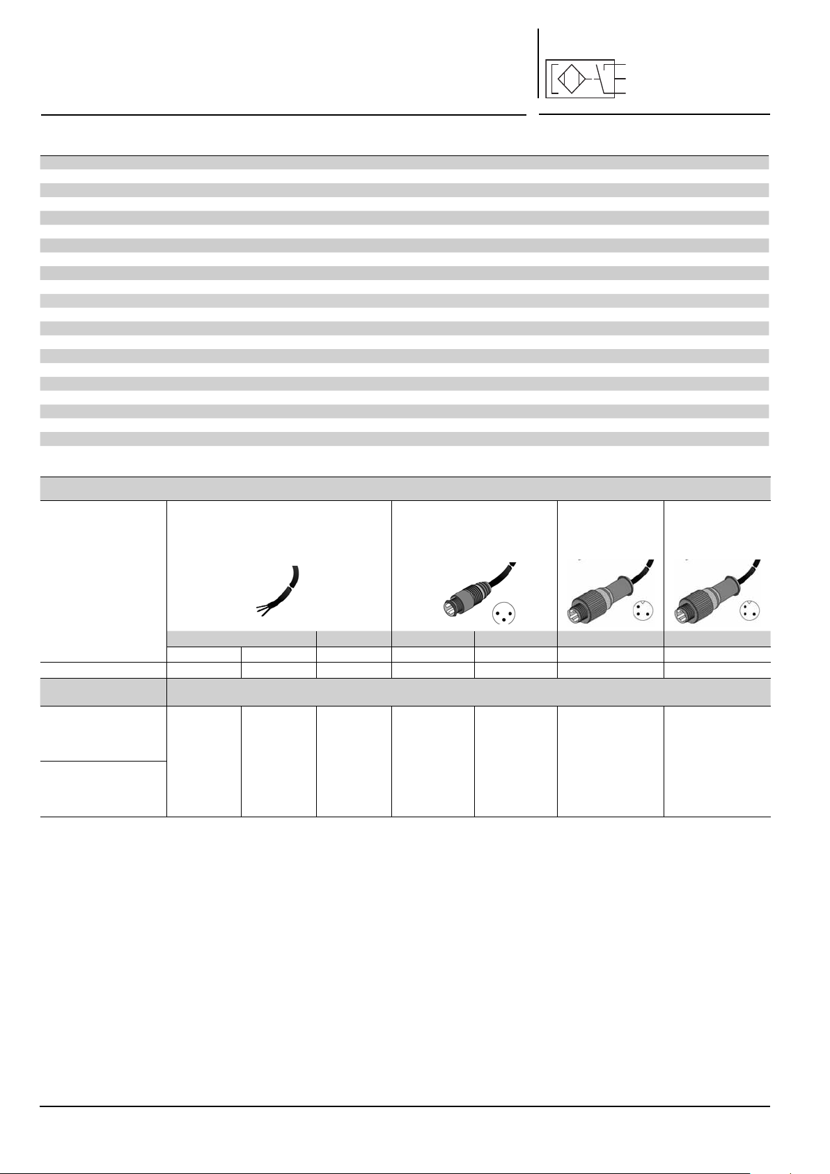
CHOIX DU DETECTEUR
Tension
câble PUR 2 ou 5 m
3 conducteurs 0,14 mm
extrémité dénudée,
IP67
Raccordement
2 mètres 5 mètres 0,3 mètre 0,3 mètre 0,3 mètre 0,3 mètre
PNP NPN PNP PNP NPN PNP PNP
Masse (g) 22 22 50 7 7 16 25
Adaptable sur
vérins type:
PEC
PES 453
PESΩ (453)
CSC - CGT
ISOCLAIR (2)
K - P2B - P2L
PES 450 - PES Ω (450)
PCN
(1) Détecteur permettant l’adaptation directe sur vérins à rainures "T"
(2) Nécessite un kit de fi xation, voir pages 7 et 8
(3) Marché U.S.
(1)
PNP-FL2-00-U
détecteur livré avec clip de maintien de câble et butée de position de réglage
NPN-FL2-00-U
(3)
PNP-FL5-00 PNP-QDS-M8-U
10 à 30 Volt CC
2
CODE STANDARD détecteur
câble PUR long. 0,3 m + connec-
teur mâle encliquetable et Ø M8
3 broches,
IP67
NPN-QDS-M8-U
(3)
câble PUR 0,3 m
connecteur mâle à
vis Ø M12 3 broches,
IP67
PNP-QDS-M12 PNP-QDS-M12-F
+
câble PVC 0,3 m
connecteur mâle
inox à vis Ø M12 3
broches, IP69K
ACCESSOIRES ET AUTRES CARACTERISTIQUES ELECTRIQUES : voir page suivante
+
3
Page 4
_
PROTECTION ELECTRIQUE
!
5 m
br = 1
blk= 4
blu= 3
143
PVC
5 m
br = 1
blk= 4
blu= 3
1
4
3
2
PVC
1
3
4
CM5
• Sortie protégée contre les courts-circuits éventuels de la charge lorsque le courant de sortie est inférieur ou égal à 0,1 A.
• Le branchement incorrect des fi ls de sortie peut entraîner le non fonctionnement ou la destruction du mini-détecteur.
• Malgré la protection interne, dans le cas de charge selfi que, il est recommandé d’utiliser une diode (montée en parallèle) sur la
charge
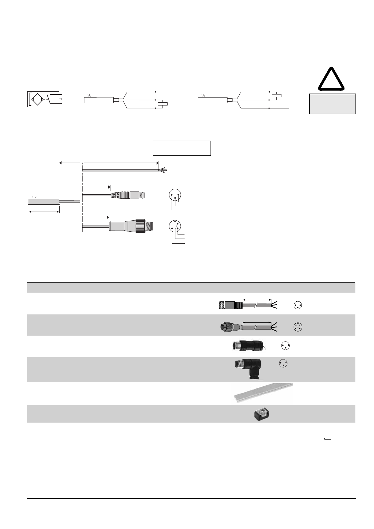
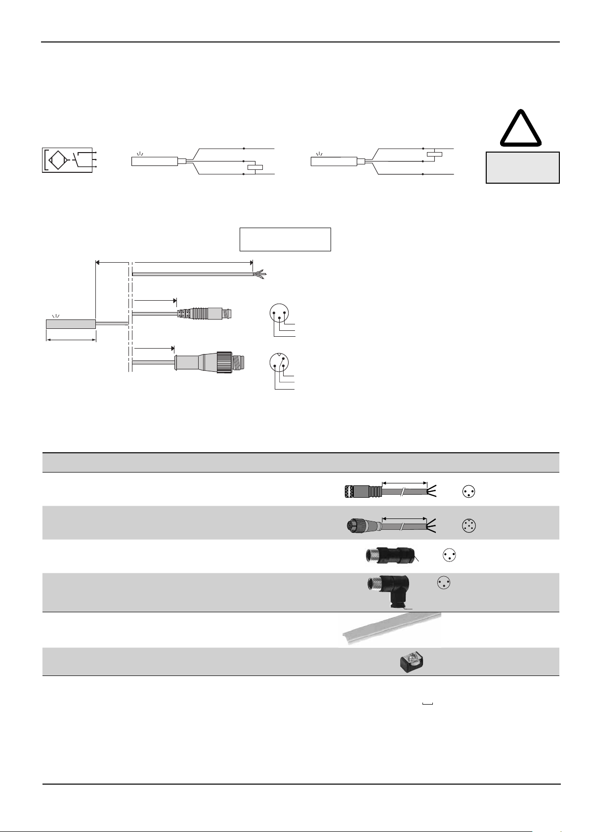
RACCORDEMENT
1 (+)
4
3 ( --)
PNP
marron
noir
bleu
1
4
3
+
charge
_
NPN
marron
noir
bleu
1
charge
4
3
+
Respecter
_
les polarités
CONNEXIONS DES DETECTEURS MAGNETO-RESISTIFS : 3 possibilités
Vue côté des broches
des connecteurs mâles
2 / 5 m
0,3 m
1
3
4
+
1
4
+
_
charge
charge
25 mm
0,3 m
3
Recommandation de montage :
S'assurer que le câble électrique d'alimentation du détecteur n'est pas soumis à des tractions / torsions néfastes à sa durée de vie
Sortie par câble PUR Ø 3 mm, extrémité dénudée
3 conducteurs 0,14 mm
Fil bleu : pôle Fil noir : charge
Sortie par câble PUR Ø 3 mm avec connecteur mâle
encliquetable + à vis Ø M8 mm - 3 broches
Sortie par câble PUR Ø 3 mm résistant aux liquides de coupe
avec connecteur mâle à vis Ø M12 - 3 broches
2
- Fil marron : pôle +
ACCESSOIRES
désignation
allonge par câble en PVC, longueur 5 m, 3 conducteurs 0,25 mm2 avec 1
connecteur M8 femelle vissable (l’autre extrémité nue) (1), IP67
allonge par câble en PVC, longueur 5 m, 3 conducteurs 0,25 mm
2
avec 1 connecteur M12 femelle vissable (l’autre extrémité nue) (1), IP67
connecteur droit Ø M8, 3 broches femelles, IP67
3
connecteur coudé à 90° Ø M8, orientable 90° x 90°,
3 broches femelles, IP67
1
4
CM5
réglette de protection des rainures et maintien des câbles
(vendue par multiple de 1 m - longueur mini = 1 m
Bloc de mémorisation de la position de réglage du détecteur
(1) Raccordement des détecteurs, fi l marron = +, fi l bleu = -, fi l noir = charge
(2) Pour votre commande, nous préciser - code: 88100746 complété de la longueur (en mètre) souhaitée - exemple: 2 m = 88100746 2
88100239
88100238
88100202
88100203
88100746
N199-1162
code
(2)
4
Page 5
PROCEDURE DE MONTAGE ET DEMONTAGE DES DETECTEURS "T"
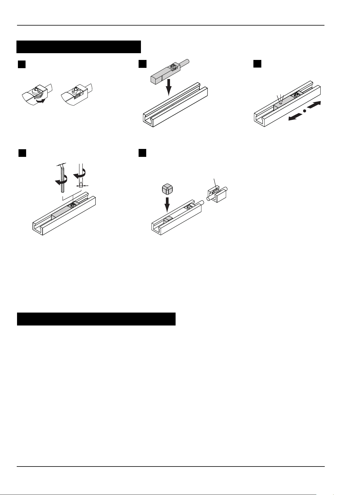
MONTAGE DU DETECTEUR
A
D
sw 1,5 mm
90°
0,5 Nm
0,6 x 3,5 mm
B
E
Clip
C
A - Tourner l'écrou profi lé du détecteur de 90° afi n qu'il s'escamote à l'intérieur
B - Appliquer le détecteur au fond de la rainure
C - Positionner le détecteur au point de détection souhaité
D - Tout en maintenant le détecteur sur sa position, serrer la vis (1/2 de tour).
Couple maxi de serrage de la vis: 0,5 N.m
E - Mémoriser la position de réglage à l'aide du bloc de mémorisation et maintenir le câble dans la rainure à
l'aide du clip
DEMONTAGE/REMONTAGE DU DETECTEUR
1 - Desserrer l'écrou profi lé de 90° et désengager le câble du clip
2 - Les opérations suivantes, d'adaptation, réglage et serrage sont identiques aux phases B, C et D ci-dessus
5
Page 6
RECOMMANDATIONS DE MONTAGE
5
34
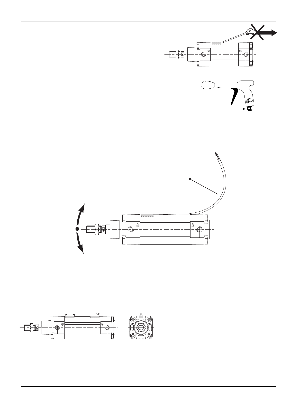
S'assurer que le câble électrique d'alimentation du détecteur n'est
pas soumis à des tractions/torsions néfastes à sa durée de vie.
- Eviter les câbles trop courts
- Ne pas tirer sur les câbles
- Ne pas plier les câbles
- Respecter un rayon de courbure de 15 mm mini. en montage statique
- Ne pas écraser les câbles notamment lors d'utilisation de pince à
collier serre-câble. A régler impérativement sur serrage mini
(pour câble Ø 2 - 2,5 mm).
- Eviter le montage des détecteurs de positions à proximité
de toute présence ferromagnétique ou électromagnétique intense
(bobine, pince à soudage, etc ...).
- Ne pas utiliser en environnement d'huiles ou solvants incompatibles
avec le câble
en PUR ou PVC suivant version (si nécessaire, nous consulter).
Min.
Nettoyage avec solution alcaline (eau savonneuse).
Applications mobiles:
Lors de montage dynamique, le câble subit des mouvements de balancier dus à la masse des connecteurs ou à
un excès de longueur de câble qui peuvent provoquer sa rupture. Il est recommandé d'utiliser la réglette de protection et de maintien des câbles dans la rainure (proposée en accessoire) et de respecter un rayon de courbure
du câble de 120 mm mini.
Vers partie fi xe
120 mm
mi
n
.
MISE EN SERVICE
-
Respecter les valeurs limites de fonctionnement (électrique, mécanique, température) défi nies dans cette documentation.
- Aucune modifi cation ne peut être réalisée sur le matériel sans notre accord préalable.
ENCOMBREMENTS
Les détecteurs magnétiques se fi xent directement dans une des rainures du vérin. La détection de positions
rapprochées ou les très faibles courses nécessitent d'adapter 1 détecteur par rainure.
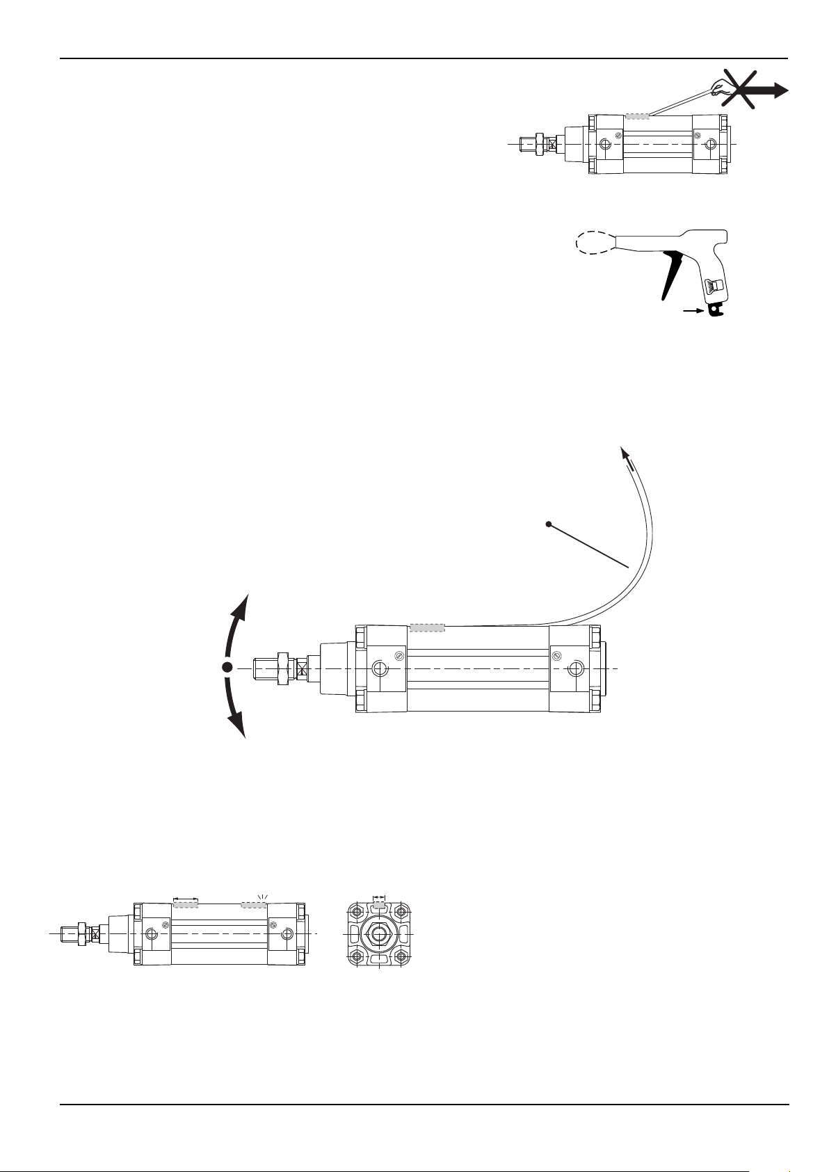
RECOMMANDATIONS DE MONTAGE
Pour contrôler les positions situées aux extrémités maximales
du vérin, les détecteurs doivent être montés dans le sens suivant :
vérin PES serie 453
Ø 32-100: câble orienté vers le tube
6
Page 7
A
3
5
5
4
3
2
4
466
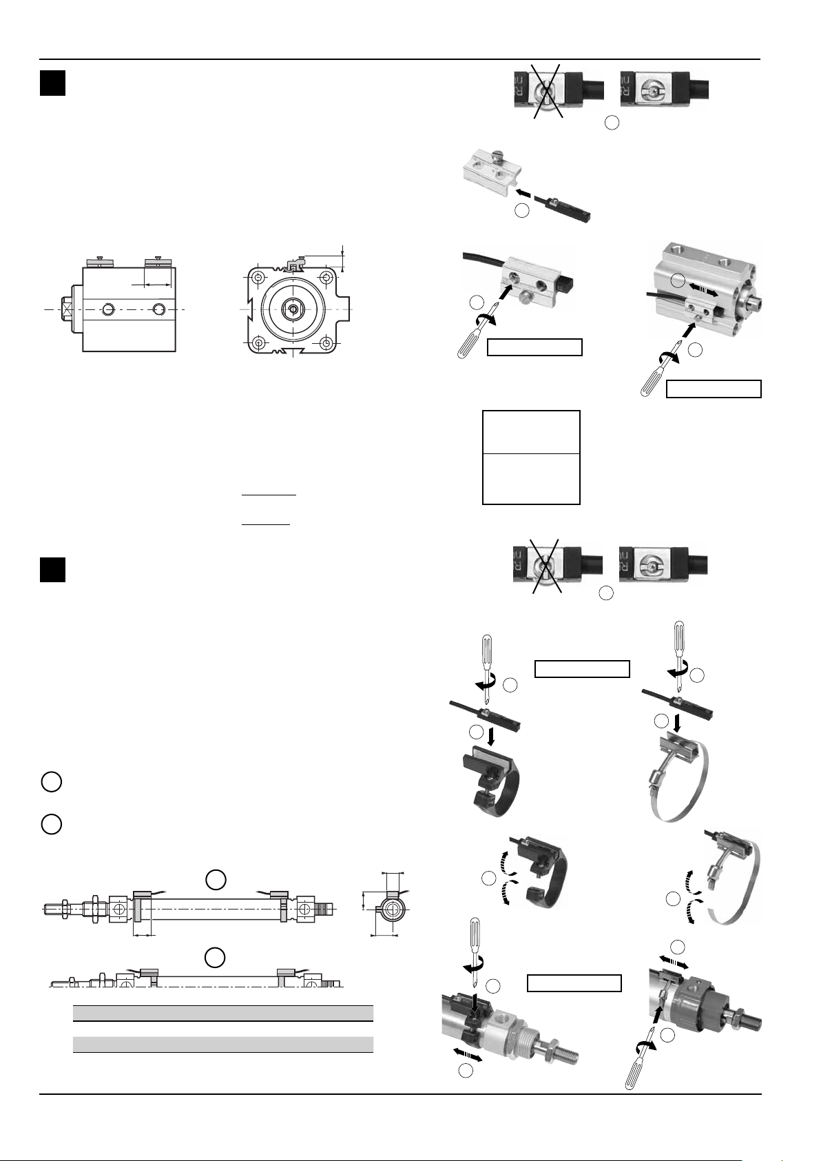
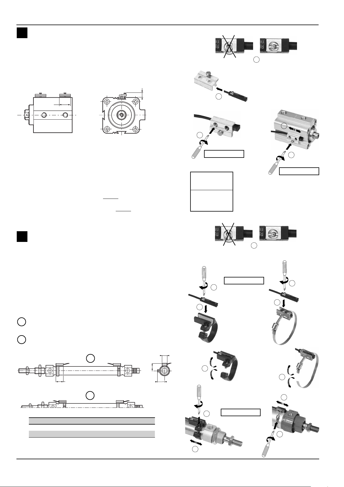
MONTAGE SUR VERINS A QUEUE D'ARONDE
1 - Tourner l'écrou profi lé du détecteur de 90° afi n qu'il s'escamote
à l'intérieur
2 -
Placer le détecteur dans la rainure du kit de fi xation
3 - Tout en maintenant le détecteur sur sa position, serrer la
vis (1/2 de tour)
4 - Placer l'ensemble détecteur + kit de fi xation dans la rainure du
vérin et le positionner au point de détection souhaité
5 - Tout en maintenant l'ensemble sur sa position, serrer la vis du
kit de fi xation
9
1
25/30
1
3
2
NOTA :
vérins K Ø 8 - 12 mm : 2 rainures en 1 et 2
Ø 16 - 100 mm : 3 rainures en 1,2 et 3
Pour contrôler les positions situées aux extrémités maximales du
vérin, les détecteurs doivent être montés dans le sens suivant :
Vérin K :
Ø8-10-12-16 équipés de détecteur MR :
le détecteur dépasse de 5 mm des faces externes du vérin
Ø8-10-12 : câble orienté vers l’intérieur du vérin
Ø16 fond avant : position indifférente
Ø16 fond arrière : câble orienté vers l’intérieur du vérin
Vérin P2B/P2L : position indifférente
B
MONTAGE SUR VERIN ROND Ø 8 à 80 :
1 - Tourner l'écrou profi lé du détecteur de 90° afi n qu'il s'escamote
à l'intérieur
2 -
Appliquer le détecteur au fond de la rainure du collier
3 - Tout en maintenant le détecteur sur sa position, serrer la
vis (1/2 de tour)
4 - ouvrir le collier et placer l'ensemble autour du tube
5 -
Positionner l'ensemble détecteur + collier au point de détection
souhaité
6 -
Tout en maintenant l'ensemble sur sa position, serrer la vis du
collier
Possibilité de montage des détecteurs magnétiques pour
contrôle de positions intermédiaires
Possibilité de montage des détecteurs avec sortie électrique
I
dirigée vers le tube du vérin : pour tous les diamètres
Possibilité de montage des détecteurs avec sortie électrique
II
dirigée vers les fonds du vérin en retournant de 180° l'ensemble
détecteur + collier de fi xation: pour les diamètres 25 à 80
13
I
D
C. max: 0,5 N.m
CODE KIT
DE FIXATION
N199-1163
avec fi xation
plastique
2
1
C. max: 0,5 N.m
C. max: 0,4 N.m
avec fi xation inox
3
2
25/30
E
5
II
C. max: 0,5 N.m
Ø vérin 8 101216202532405063
D 14,5 15,5 15 16,5 19 21,5 26,5 31 38 45
E 13,5 14,5 16,5 19 20,5 23 29,5 31,5 36,5 43,5
7
Page 8
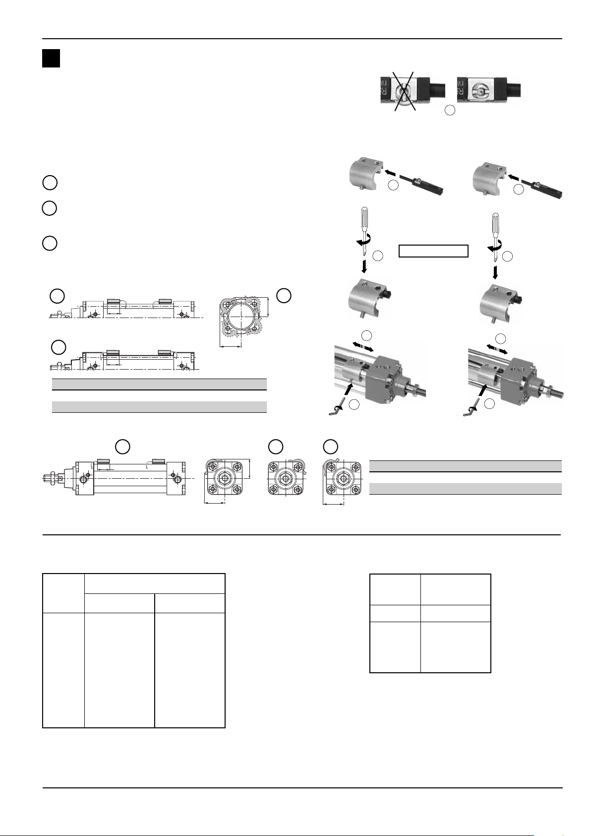
C
3452543
2
25/30
MONTAGE SUR VERIN A TUBE PROFILE OU A TIRANTS:
1 - Tourner l'écrou profi lé du détecteur de 90° afi n qu'il s'escamote
à l'intérieur
Placer le détecteur dans la rainure du kit de fi xation
2 3 - Tout en maintenant le détecteur sur sa position, serrer la
vis (1/2 de tour)
4 - Placer l’ensemble sur l’un des 4 bossages ou tirants et le
positionner au point de détection souhaité
5 - S'assurer que le détecteur est en contact avec le tube et
bloquer l'ensemble sur le vérin (clé six pans 2 mm)
Possibilité de montage des détecteurs magnétiques pour
I
contrôle de positions intermédiaires.
Possibilité de montage des détecteurs avec sortie électrique
II
dirigée vers l’arrière du vérin en adaptant le détecteur + la bride
de fi xation.
Possibilité de montage des détecteurs sur n’importe lequel
III
des 4 bossages ou tirants.
VERINS PES-PCN A TIRANTS Ø 25 à 200
Vérin à tube
profi lé
1
Vérin à tirants
C. max: 0,5 N.m
I
25/30
II
Ø vérin 25 32 40 50 63 80 100 125 160 200
D 243033384450697789104
E 242630353949616987101
D
III
E
VERINS PES A TUBE PROFILE Ø 32 à 125
E max.
II
III
Ø vérin 32 40 50 63 80 100 125
D 28323741586573
E 28313640546273
E max.
I
25/30
D
CODE KIT DE FIXATION VERINS RONDS CODE KIT DE FIXATION VERINS
A TUBE PROFILE OU A TIRANTS
Ø
du vérin
8-10
12
16
20
25
32
40
50
63
80
CODE KIT DE FIXATION
plastique inox
N199-1038
N199-1039
N199-1040
N199-1041
N199-1042
N199-1043
-
-
-
N199-1037
N199-1054
N199-1054
N199-1055
N199-1055
N199-1056
N199-1058
N199-1044
N199-1045
N199-1046
Ø
du vérin
25
32-40
50-63-80
100
125-160-200
CODE KIT
DE FIXATION
N199-1051
N199-1047
N199-1048
N199-1049
N199-1050
8
Page 9
MAGNETIC POSITION DETECTORS
for "T" grooves
GB
reed switch type
DETECTOR CHARACTERISTICS
MAX. SWITCHING POWER DC = 5 W - AC = 5 VA
SWITCHING VOLTAGE see below
MAX. SWITCHING CURRENT 100 mA
SHORT-CIRCUIT PROTECTION no
REVERSE POLARITE PROTECTION yes (without LED function)
OVERLOAD PROTECTION no
VOLTAGE DROP (EN 60947-5-2) < 5 volt
BREAKDOWN VOLTAGE 230 V DC
CONTACT RESISTANCE 0,2 ohm max.
INSULATION RESISTANCE 10
SENSITIVITY 2,1 mTesla (21 Gauss)
REPONSE TIME 0,1 ms opening - 0,6 ms closing
REPEATABILITY < ± 0,2 mm
WORKING TEMPERATURE - 25°C , + 70°C
HOUSING
CABLE PUR, resistant to cutting oils
DEGREE OF PROTECTION (IEC 60529) IP 67
PROTECTION CLASS cable outlet: class II, M8 and M12 connection: class III
APPROVAL CE
SIGNAL INDICATION yellow diode (LED) which lights up when the contact is established
8
ohms at 100 V
PA + GF overmoulding
Series
REED
Type
2 wires
CHOICE OF DETECTOR
Voltage
Connection
weight (g) 22 50 7 7 16
compatible
cylinders
PEC
PES 453
PES Ω (453)
CSC - CGT
ISOCLAIR (2)
K - P2B - P2L
PES 450 - PES Ω (450)
PCN
(1) Detector designed for direct fi tting to "T" cylinder grooves
(2) Fastening kit required, see pages 7 and 8
(3) U.S. market
(1)
5 to 120 Volt AC/DC
PUR lead, 2 or 5 m long,
2 wires 0.14 mm2,
stripped ends
2 metres 5 metres 0,3 metre 0,3 metre 0,3 metre
STANDARD CATALOGUE NUMBER detector
detector supplied with cable holding clip and adjustment position stop
REED-FL2-00 REED-FL5-00 REED-QDS-M8E
0.3 m PUR lead + 3-pin
plug-in male
connector and Ø M8
connection of pins
1 - 4 1 - 3
REED-QDS-M8U
5 to 50 Volt AC
5 to 60 Volt DC
(3)
0.3 m PUR lead + 3-pin
screw-type male
connec tor, Ø M12
REED-QDS-M12E
ACCESSORIES AND OTHER ELECTRICAL CHARACTERISTICS: see following page
A separate Declaration of Incorporation relating to Council Directive 98
Please provide acknowledgement number and serial numbers of products concerned.
This product complies with the essential requirements of the EMC-Directive 89/336/EEC and amendments. A
separate Declaration of Conformity is available on request.
/37
/EC Annex II B is available on request.
1
Page 10
5 m
br = 1
blk= 4
blu= 3
143
PVC
5 m
br = 1
blk= 4
blu= 3
1
4
3
2
PVC
1
3
4
CM5
MAXIMUM ELECTRICAL CHARACTERISTICS AND PROTECTION OF MAGNETIC DETECTOR (REED SWITCH)
Max. switching current : 100mA
For inductive loads (valves, contactors, …), external protection is required to avoid damage caused by switch-off voltage peaks. Use
freewheeling diode, transil diode, varistor or similar.
PARTICULAR APPLICATIONS (valid for all models)
• Detectors used for direct control of incandescent lamps:
The capacity specifi ed on the lamp is based on its resistance when hot. When switched on, the resistance of the cold lamp is very low. Therefore,
the current rises quickly and may exceed the reed switch rating. Allowance should therefore be made for the real power of the cold lamp.
• With leads longer than 10 m, a 200 Ω resistor must be fi tted in series with the detector to reduce the capacitive effect caused by the wiring.
REED SWITCH CONNECTION : 4 possibilities
View from male contact
side of connector
30 mm
2 / 5 m
0,3 m
3
4
0,3 m
3
4
0,3 m
3
PUR lead outlet Ø 3 mm with stripped ends,
2 wires 0.14 mm
2
- brown wire = +
blue wire = -
PUR lead outlet Ø 3 mm with 3-pin plug-in male
1
connector + screw Ø 8 mm (2 pins connected, 1 and 4)
PUR lead outlet Ø 3 mm with 3-pin plug-in male
1
connector + screw Ø 8 mm (2 pins connected, 1 and 3)
1
PUR lead outlet Ø 3 mm resistant to cutting fl uids, with
4
3-pin screw-type male connector, Ø M12 (2 pins connected, 1 and 4)
Mounting recommendation:
Do not subject the detector's power supply cable to damaging traction / torsion during its service life.
ACCESSORIES
description
extension consisting of PVC, length 5 m, 3 wire conductors 0.25 mm
with 1 screw-on femal M8 connector (other end plain)
, IP67
extension consisting of PVC, length 5 m, 3 wire conductors 0.25 mm
with 1 screw-on femal M12 connector (other end plain)
, IP67
straiht 3-pin female connector Ø M8, IP67
Right angle 3-pin female connector Ø M8, orientable 90° x 90°, IP67
Cable cover and holder
(sold by the metre - minimum length = 1 m)
Block of memorizing position of adjustment detector
(1) For your order please add the requested length (in metres) to the order code - example: 2 m = 88100746 2
2
2
CM5
catalogue
88100239
88100238
88100202
3
1
4
88100203
«T» slot 88100746 (1)
N199-1162
number
ASSEMBLY OF CABLE COVER AND HOLDER
2
Page 11
MAGNETIC POSITION DETECTORS
for "T" grooves
magneto-resistive (MR)
DETECTOR CHARACTERISTICS
MAX. SWITCHING POWER 3 W
SWITCHING VOLTAGE 10 to 30 V DC
MAX. SWITCHING CURRENT 100 mA
WIRING PNP - NPN (3)
REVERSE POLARITE PROTECTION yes
OVERLOAD PROTECTION yes
SHORT-CIRCUIT PROTECTION yes
VOLTAGE DROP (EN 60947-5-2) < 1,5 volt (I = 50 mA)
MAX. LEAKAGE CURRENT < 50 µA
MAX. ALLOWABLE OVERVOLTAGE 32 VCC max. (100 ms)
SENSITIVITY 2 mTesla (20 Gauss)
RESPONSE TIME 110 µs opening - 220 µs closing
REPEATABILITY < 0,2 mm
WORKING TEMPERATURE - 25°C , + 85°C
HOUSING
CABLE PUR, resistant to cutting oils (PVC for M12 IP69K version)
DEGREE OF PROTECTION
PROTECTION CLASS class III
SIGNAL INDICATION yellow diode (LED) which lights up during switching
APPROVAL CE - UL and cUL for 2 m and M8 connection
(CEI 60529) IP67
< 2,5 volts (I = 100 mA)
PA + FG overmolding
Series
PNP-NPN
Type
3 wires
CHOICE OF DETECTOR
Voltage
PUR lead, 2 or 5 m long,
3 wires 0.14 mm2,
stripped ends,
IP67
Connection
2 metres 5 metres
PNP NPN PNP PNP NPN PNP PNP
weight (g) 22 22 50 7 7 16 25
compatible
cylinders:
PEC
PES 453
PES Ω (453)
CSC - CGT
ISOCLAIR (2)
K - P2B - P2L
PES 450 - PES Ω (450)
PCN
(1) Detector allow direct fi tting on "T" cylinder grooves
(2) Need a kit of fi xation, see pages 7 and 8
(3) U.S. market
(1)
PNP-FL2-00-U
NPN-FL2-00-U
(3)
STANDARD CATALOGUE NUMBER detector
detector supplied with cable holding clip and adjustment position stop
PNP-FL5-00 PNP-QDS-M8-U
10 to 30 Volt DC
0,3 m
PUR
lead + 3-pin
plug-in male
connector and Ø M8,
IP67
0,3 metre 0,3 metre 0,3 metre
NPN-QDS-M8-U
(3)
0,3 m PUR lead + 3-pin
screw-type male
connec tor, Ø M12,
IP67
PNP-QDS-M12 PNP-QDS-M12-F
0,3 m PVC lead + 3-pin
screw-type male
connec tor, Ø M12,
IP69K
0,3 metre
ACCESSORIES AND OTHER ELECTRICAL CHARACTERISTICS: see following page
3
Page 12
5 m
br = 1
blk= 4
blu= 3
143
PVC
5 m
br = 1
blk= 4
blu= 3
1
4
3
2
PVC
1
3
4
CM5
ELECTRICAL PROTECTION
!
• Output protected against short-circuit as long as the output current is restricted to 0.1 A.
• Improper wire connection may prevent the detector from operating or even destroy it.
• It is recommended to install a protection diode (mounted in parallel) on an inductive load in spite of the internal protection.
CONNECTION
1 (+)
4
3 ( --)
PNP
brown
black
blue
1
+
4
load
_
3
NPN
brown
black
blue
1
4
3
load
+
Polarities
_
to be observed
CONNECTION OF MAGNETO-RESISTIVE DETECTORS: 3 possibilities
View from male contact
side of connector
25 mm
0,3 m
0,3 m
2 / 5 m
1
3
4
+
load
_
1
3
4
load
+
_
PUR lead outlet Ø 3 mm, stripped ends
3 wires 0.14 mm
Blue wire : -
Black wire : load
PUR lead outlet Ø 3 mm with 3-pin plug-in male
connector + screw Ø M8
PUR lead outlet Ø 3 mm resistant to cutting fl uids,
with 3-pin screw-type male connector Ø M12
2
- Brown wire : +
Mounting recommendation:
Do not subject the detector's power supply cable to damaging traction / torsion during its service life.
ACCESSORIES
description
extension consisting of PVC, length 5 m, 3 wire conductors 0.25 mm
with 1 screw-on femal M8 connector (other end plain) (1)
extension consisting of PVC, length 5 m, 3 wire conductors 0.25 mm
with 1 screw-on femal M12 connector (other end plain) (1)
straiht 3-pin female connector Ø M8, IP67
Right angle 3-pin female connector Ø M8, orientable 90° x 90°, IP67
Cable cover and holder
(sold by the metre - minimum length = 1 m)
Block of memorizing position of adjustment detector
(1) Detector connection, brown wire = +, blue wire = -, black wire = load
(2) For your order please add the requested length (in metres) to the order code - example: 2 m = 88100746 2
2
2
CM5
catalogue
88100239
88100238
88100202
3
1
4
88100203
«T» slot 88100746 (2)
N199-1162
number
4
Page 13
ASSEMBLY AND DISASSEMBLY PROCEDURE FOR T-SLOT DETECTORS
DETECTOR ASSEMBLY
A
D
sw 1,5 mm
90°
0,5 Nm
0,6 x 3,5 mm
B
E
Clip
C
A - Turn the detector's knurled nut by 90° so that it is retracted inside.
B - Press the detector down into the groove.
C - Position the detector at the desired sensing point.
D - Hold the detector in place as you tighten the screw (½ turn).
Max. screw tightening torque: 0,5 N.m
E - Fix the adjustment position with the memory unit and secure the cable into the groove with the clip.
DETECTOR DISASSEMBLY/REASSEMBLY
1 - Loosen the knurled nut by 90° and remove the cable from the clip.
2 - The following installation, adjustment and tightening steps are identical to steps B, C and D described above.
5
Page 14
MOUNTING RECOMMENDATIONS
5
34
Make sure that the power cable for the detector is not subject to tension
or torsional stress throughout its lifetime.
- Avoid using cables which are not long enough.
- Do not pull on the cables.
- Do not fold the cables.
- Observe a minimum bending radius of 15 mm in static assembly.
- Do not pinch the cables when using a retaining ring plier. The minimum
tightening torque must be observed (for cable dia. 2 – 2.5 mm).
- Do not mount position detectors near to ferromagnetic or intense electromagnetic fi elds (solenoid coil, soldering tongs etc.).
- Check to ensure the compatibility of the PUR and PVC cables with the
oil and solvent environments (contact us, if necessary). Clean with an
alcaline solution (soapy water).
Min.
Flexible applications:
In dynamic assembly the cable is subject to oscillating movements due to the weight of the connectors or excess
cable lengths which may cause the cable to break. We recommend using the cable cover and holder (available as
accessory) in the groove and observing a minimum cable bending radius of 120 mm.
To the fi xed part
120 mm
mi
n
.
PUTTING INTO SERVICE
-
Observe the maximum/minimum (electrical, mechanical, temperature) operating ranges defi ned in this documentation.
- Any modifi cation to the equipment shall be subject to the prior approval of ASCO NUMATICS.
DIMENSIONS
The magnetic detector fi ts directly into the grooves in the cylinder body. Detection of very small movements or
very short strokes requires one detector to be installed in each groove.
INSTALLATION RECOMMENDATION
In order to control the max. end of cylinder stroke,
the detectors must be mounted in the following
direction:
PES cylinders series 453
Ø 32-100 : cable oriented towards the cylinder barrel.
:
6
Page 15
A
3
5
543
2
4
466
MOUNTING ON DOVETAIL GROOVE CYLINDERS
1 - Turn the detector's knurled nut by 90° so that it is retracted
inside.
2 - Place the detector into the fastening kits' groove.
3 - Hold the detector in place as you tighten the screw (1/2 turn).
4 - Place the detector + fastening kit unit into the cylinder groove
and position it at the desired sensing point.
5 - Hold the unit in place and tighten the screw of the fastening kit.
9
1
25/30
1
3
2
NOTE:
K cylinders Ø 8 - 12 mm : 2 grooves at 1 and 2
Ø 16 - 100 mm : 3 grooves at 1,2 and 3
In order to control the max. end of cylinder stroke, the detectors
must be mounted in the following direction:
K cylinder:
Ø8-10-12-16 with MR detector:
The detector projects by 5 mm from the outer faces of the cylinder.
Ø8-10-12: cable oriented towards the middle of the cylinder
Ø16 front cover: any position
Ø16 rear cover: cable oriented towards the middle of the cylinder
P2B/P2L cylinders : any position
B
MOUNTING ON ROUND CYLINDERS Ø 8 to 80
1 - Turn the detector's knurled nut by 90° so that it is retracted
inside.
2 - Press the detector down into the collar's groove.
3 - Hold the detector in place as you tighten the screw (1/2 turn)
4 - Open the collar and place the device around the barrel.
5 - Position the detector + collar unit at the desired sensing point.
6 - Hold the unit in place and tighten the collar screw.
C. max: 0,5 N.m
CODE
FASTENING KIT
N199-1163
plastic
mounting
C. max: 0,5 N.m
C. max: 0,4 N.m
1
stainless steel
mounting
3
It is possible to mount additional magnetic detectors for intermediate position indication.
On all diameters, it is possible to mount the detector with its
I
electrical outlet facing towards the cylinder barrel.
In order to fasten the detector on cylinder diameters 25 to 80
II
with its electrical outlet facing towards the cylinder ends,
rotate the detector + collar unit by 180°.
I
D
25/30
II
Ø cyl. 8 10 12 16 20 25 32 40 50 63
D 14,5 15,5 15 16,5 19 21,5 26,5 31 38 45
E 13,5 14,5 16,5 19 20,5 23 29,5 31,5 36,5 43,5
2
2
13
E
5
C. max: 0,5 N.m
7
Page 16

C
3452543
2
25/30
MOUNTING ON PROFILED BARREL OR TIE ROD CYLINDERS:
1 - Turn the detector's knurled nut by 90° so that it is retracted in-
side..
2 - Place the detector into the fastening kits' groove.
3 - Hold the detector in place as you tighten the screw (1/2 turn).
4 - Place the unit on one of the bosses or tie rods and position it at
the desired sensing point.
5 - Make sure that the detector is in contact with the barrel and
tighten the unit on the cylinder (use a 2 mm hexagon wrench).
It is possible to mount additional magnetic detectors.
I
for intermediate position indication.
In order to fasten the detector with its electric outlet to the rear,
II
mount the detector + the mounting bracket.
The detectors can be mounted on any one of the 4 bosses or
III
Cylinder with
profi led barrel
tie rods.
PES-PCN CYLINDERS WITH TIE RODS Ø 25 to 200
1
Cylinder with
tie rods
C. max: 0,5 N.m
I
25/30
II
Ø cyl. 25 32 40 50 63 80 100 125 160 200
D 243033384450697789104
E 242630353949616987101
D
III
E
PES CYLINDERS WITH PROFILED BARREL Ø 32 to 125
E max.
II
III
Ø cyl. 32 40 50 63 80 100 125
D 28323741586573
E 28313640546273
E max.
I
25/30
D
ROUND CYLINDERS FASTENING KIT PROFILED BARREL OR TIE ROD
CYLINDER FASTENING KIT
Ø
cylinder
8-10
12
16
20
25
32
40
50
63
80
CODE FASTENING KIT
plastic
N199-1038
N199-1039
N199-1040
N199-1041
N199-1042
N199-1043
-
-
-
stainless
steel
N199-1037
N199-1054
N199-1054
N199-1055
N199-1055
N199-1056
N199-1058
N199-1044
N199-1045
N199-1046
Ø
cylinder
25
32-40
50-63-80
100
125-160-200
CODE
FASTENING KIT
N199-1051
N199-1047
N199-1048
N199-1049
N199-1050
8
Page 17

NÄHERUNGSSCHALTER
für T-förmige Nuten
DE
ELEKTRISCHE DATEN
MAX. SCHALTLEISTUNG
SCHALTSPANNUNG
MAX. SCHALTSTROM
KURZSCHLUSSSCHUTZ nein
VERPOLUNGSSCHUTZ ja (ohne LED)
ÜBERSPANNUNGSSCHUTZ nein
SPANNUNGSABFALL (EN 60947-5-2) < 5 Volt
DURCHSCHLAGSPANNUNG 230 V DC
DURCHGANGSWIDERSTAND max. 0,2 Ohm
ISOLATIONSWIDERSTAND 10
EMPFINDLICHKEIT 2,1 mTesla (21 Gauss)
ANSPRECHZEIT 0,1 ms Öffnen - 0,6 ms Schließen
WIEDERHOLGENAUIGKEIT < ± 0,2 mm
BETRIEBSTEMPERATUR - 25°C , + 70°C
GEHÄUSE
KABEL PUR, schneidölbeständig
SCHUTZART (IEC 60529) IP 67
SCHUTZKLASSE Kabelenden Klasse II, M8- und M12-Anschlüsse Klasse III
ZERTIFIZIERUNG CE
SIGNALANZEIGE
Reed-Kontakt
DC = 5 W - AC = 5 VA
siehe unten
100 mA
8
Ohm bei 100 Volt
Thermoplastisches Gehäuse PA + GF
Leuchtdiode (LED gelb), leuchtet auf, sobald der Kontakt geschlossen ist.
Baureihe
REED
Ty p
2-adrig
KENNDATEN
Spannung
Anschluss
Gewicht (g) 22 50 7 7 16
Zylindertyp
PEC
PES 453
PES Ω (453)
CSC - CGT
ISOCLAIR (2)
K - P2B - P2L
PES 450 - PES Ω (450)
PCN
(1) Näherungsschalter für die direkte Montage in die T-Nuten der Zylinder
(2) Befestigungssatz erforderlich, siehe Seiten 7 und 8
(3) US-Markt
(1)
5 bis 120 Volt AC/DC
Kabelschwanz 2 oder 5 m aus PUR,
2-adrig, 0,14 mm
Enden abisoliert
2 m 5 m 0,3 m 0,3 m 0,3 m
Kabelhalteclip und Positionsanschlag im Lieferumfang des Näherungsschalters enthalten.
REED-FL2-00 REED-FL5-00 REED-QDS-M8E
2
STANDARD-KATALOGNUMMER Näherungsschalter
Kabelschwanz 0,3 m aus PUR
+ 3-poliger Leitungsstecker Ø M8
mit Rastverschluss
Anschluss der Pins
1 - 4 1 - 3
REED-QDS-M8U
5 bis 50 Volt AC
5 bis 60 Volt DC
(3)
Kabelschwanz 0,3 m aus PUR
+ 3-poliger Leitungsstecker Ø M12
mit Schraubverschluss
REED-QDS-M12E
ZUBEHÖR UND WEITERE ELEKTRISCHE DATEN: siehe folgende Seite
Eine Herstellererklärung im Sinne der EU-Richtlinie
bitte für die entsprechenden Produkte die Auftragsnummer und Seriennummer an.
Dieses Produkt entspricht der Richtlinie 89/336/EWG und deren Ergänzungen über die Elektromagnetische
Verträglichkeit. Eine Konformitätserklärung steht auf Anfrage zur Verfügung.
98/37
/EG Anhang II B ist auf Anfrage erhältlich. Geben Sie
1
Page 18

MAXIMALE ELEKTRISCHE DATEN UND SCHUTZBESCHALTUNG DES MAGNETISCH BETÄTIGTEN NÄHERUNGSSCHALTERS
5 m
br = 1
blk= 4
blu= 3
143
PVC
5 m
br = 1
blk= 4
blu= 3
1
4
3
2
PVC
1
3
4
CM5
(REED-KONTAKT)
Max. Schaltspannung: 100 mA
Bei Anschluss einer induktiven Last (Ventile, Relais, usw.) ist eine Schutzdiode zu legen (Freilaufdiode, Transildiode, Varistor usw.)
um eine Beschädigung der Kontakte aufgrund von Überspannungen zu vermeiden.
BESONDERHEITEN (gültig für alle Modelle)
• Direkt betätigter Näherungsschalter mit Reed-Kontakt:
Die auf der Diode angegebene Leistung bezieht sich auf den Widerstand, wenn diese warm wird. Beim Einschalten ist der Widerstand der kalten Diode sehr
gering, der Strom steigt sehr schnell an und kann die Leistung des Reed-Kontakts übersteigen. Es ist daher empfehlenswert, die tatsächliche Leistung der kalten
Diode zu berücksichtigen.
• Bei einem Kabelschwanz länger als 10 m ist ein zusätzlicher Widerstand von 200 Ω in Reihe mit dem Näherungsschalter vorzusehen, um die Kapazität, die sich
aus der Leitungslänge ergibt, zu reduzieren.
REED-SCHALTER-ANSCHLUSS: 4 Möglichkeiten
Ansicht
auf Steckerseite
2 / 5 m
0,3 m
3
4
30 mm
0,3 m
3
4
0,3 m
3
Montageempfehlung:
Achten Sie darauf, dass das Spannungsversorgungskabel des Näherungsschalters während der gesamten Lebensdauer ohne Zugbelastung verlegt
und nicht verdreht wird.
Kabelschwanz aus PVC Ø 3 mm mit abisolierten
Enden, 2adrig, 0,14 mm2 - braune Litze = +
blaue Litze = -
Kabelschwanz aus PVC Ø 3 mm mit 3poligem Leitungsstecker
1
Ø 8 mm mit Rastverschluss (2 Pole, 1 und 4, angeschlossen)
Kabelschwanz aus PVC Ø 3 mm mit 3poligem Leitungsstecker
1
Ø 8 mm mit Rastverschluss (2 Pole, 1 und 3, angeschlossen)
1
4
Kabelschwanz aus PVC, Ø 3 mm, schneidölbeständig, mit 3poligem Leitungsstecker Ø M12 mit Schraubverschluss (2 Pole, 1 und
4, angeschlossen)
ZUBEHÖR
Bezeichnung
Artikel-Nr.
Verlängerungskabel aus PVC, 5 m lang, 3adrig 0,25 mm2, mit 1 Leitungsdose M8 mit Schraubverschluss (anderes Ende abisoliert), IP67
Verlängerungskabel aus PVC, 5 m lang, 3adrig 0,25 mm2, mit 1 Leitungsdose M12 mit Schraubverschluss (anderes Ende abisoliert), IP67
Gerade Leitungsdose Ø M8, 3-polig, IP67
Winkelleitungsdose CØ M8, um 90° umsetzbar, 3-polig, IP67
Kabelabdeckung und -halterung
(Meterware - Mindestlänge = 1 m)
Positionsspeicher
(1)
Bei der Bestellung bitten wir die gewünschte Länge (in m) an die Artikel-Nr. hinzuzufügen - Beispiel:
MONTAGE DER KABELABDECKUNG UND -HALTERUNG
3
1
4
CM5
2 m = 88100746 2
88100239
88100238
88100202
88100203
88100746
N199-1162
(1)
2
Page 19

NÄHERUNGSSCHALTER
für T-förmige Nuten
magnetoresistiv (MR)
ELEKTRISCHE DATEN
MAX. SCHALTLEISTUNG 3 W
SCHALTSPANNUNG 10 bis 30 VCC
MAX. SCHALTSTROM 100 mA
ANSCHLUSS PNP - NPN (3)
VERPOLUNGSSCHUTZ ja
ÜBERSPANNUNGSSCHUTZ ja
KURZSCHLUSSSCHUTZ ja
SPANNUNGSABFALL (EN 60.947-5-2) < 1,5 Volt (I = 50 mA)
MAX. VERLUSTSTROM < 50 µA
ZUL. ÜBERSPANNUNG max. 32 VDC (100 ms)
EMPFINDLICHKEIT 2 mTesla (20 Gauss)
ANSPRECHZEIT 110 µs Öffnen - 220 µs Schließen
WIEDERHOLGENAUIGKEIT < 0,2 mm
BETRIEBSTEMPERATUR - 25°C , + 85°C
GEHÄUSE
KABEL PUR, schneidölbeständig (PVC bei der Version M12 IP69K)
SCHUTZART (IEC 60529) IP67 / IP69K
SCHUTZKLASSE Klasse III
SIGNALANZEIGE Leuchtdiode (LED gelb), leuchtet auf, sobald der Kontakt geschlossen ist
ZERTIFIZIERUNG CE - UL und cUL für 2 m-Anschlüsse und M8-Versionen
< 2,5 Volt (I = 100 mA)
Thermoplastisches Gehäuse PA + GF
PNP-NPN
Baureihe
Ty p
3-adrig
KENNDATEN
Spannung
Kabelschwanz 2 oder 5 m aus PUR,
3-adrig, 0,14 mm
Enden abisoliert,
IP67
ANschluss
2 m 5 m 0,3 m 0,3 m 0,3 m 0,3 m
PNP NPN PNP PNP NPN PNP PNP
Gewicht (g) 22 22 50 7 7 16 25
Zylinder
PEC
PES 453
PESΩ (453)
CSC - CGT
ISOCLAIR (2)
K - P2B - P2L
PES 450 - PES Ω (450)
PCN
(1) Näherungsschalter für die direkte Montage in die T-Nuten der Zylinder
(2) Befestigungssatz erforderlich, siehe Seiten 7 und 8
(3) US-Markt
typ:
(1)
Kabelhalteclip und Positionsanschlag im Lieferumfang des Näherungsschalters enthalten.
PNP-FL2-00-U
STANDARD-KATALOGNUMMER Näherungsschalter
NPN-FL2-00-U
(3)
2
10 bis 30 Volt DC
Kabelschwanz 0,3 m aus PUR
+ 3-poliger Leitungsstecker Ø M8
mit Rastverschluss
PNP-FL5-00 PNP-QDS-M8-U
IP67
NPN-QDS-M8-U
(3)
PUR-Kabelschwanz
0,3 m + 3-poliger Lei-
tungsstecker ØM12 mit
Schraubverschluss, IP67
PNP-QDS-M12 PNP-QDS-M12-F
PVC-Kabelschwanz 0,3 m
+ 3-poliger Leitungsste-
cker ØM12 mit Schraub-
verschluss, IP69K
ZUBEHÖR UND WEITERE ELEKTRISCHE DATEN: siehe folgende Seite
3
Page 20

_
SCHUTZBESCHALTUNG
!
5 m
br = 1
blk= 4
blu= 3
143
PVC
5 m
br = 1
blk= 4
blu= 3
1
4
3
2
PVC
1
3
4
CM5
• Der Ausgang ist gegen Kurzschluss geschützt, solange der Ausgangsstrom auf 0,1 A beschränkt wird.
• Unsachgemäßer elektrischer Anschluss verursacht eine Fehlfunktion des Näherungsschalters oder kann diesen zerstören.
• Trotz des internen Schutzes ist bei Anschluss einer induktiven Last eine Schutzdiode parallel zur induktiven Last zu legen.
ANSCHLUSS
1 (+)
4
3 ( --)
PNP
braun
schwarz
blau
1
+
4
Last
_
3
NPN
braun
schwarz
blau
1
+
4
Last
_
Bitte Polarität
beachten
3
ANSCHLUSS DER MAGNETORESISTIVEN NÄHERUNGSSCHALTER: 3 Möglichkeiten
Ansicht
auf Steckerseite
2 / 5 m
0,3 m
1
3
4
+
25 mm
Montageempfehlung:
Achten Sie darauf, dass das Spannungsversorgungskabel des Näherungsschalters während der gesamten Lebensdauer ohne Zugbelastung verlegt
und nicht verdreht wird.
0,3 m
3
Last
1
4
Last
+
_
Kabelschwanz aus PVC Ø 3 mm mit abisolierten Enden,
3adrig, 0,14 mm
Litze blau = Litze schwarz = Last
Kabelschwanz aus PVC Ø 3 mm mit 3poligem Leitungsstecker
mit Rastverschluss + Schraube Ø M8
Kabelschwanz aus PVC Ø 3 mm, schneidölbeständig, mit
ligem Leitungsstecker Ø M12 mm mit Schraubverschluss
2
Litze braun = +
3po-
ZUBEHÖR
Bezeichnung
Verlängerungskabel aus PVC, 5 m lang, 3adrig 0,25 mm2, mit 1
Leitungsdose M8 mit Schraubverschluss (anderes Ende abisoliert) (1),
IP67
Verlängerungskabel aus PVC, 5 m lang, 3adrig 0,25 mm2, mit 1 Leitungs-
dose M12 mit Schraubverschluss (anderes Ende abisoliert) (1)
Gerade Leitungsdose Ø M8, 3-polig, IP67
Winkelleitungsdose CØ M8, um 90° umsetzbar, 3-polig, IP67
Kabelabdeckung und -halterung
(Meterware - Mindestlänge = 1 m)
Positionsspeicher
(1) Anschluss der Näherungsschalter: braune Litze = +, blaue Litze = -, schwarze Litze = Last
(2)
Bei der Bestellung bitten wir die gewünschte Länge (in m) an die Artikel-Nr. hinzuzufügen - Beispiel:
, IP67
3
1
4
CM5
2 m = 88100746 2
Artikel-Nr.
88100239
88100238
88100202
88100203
88100746
N199-1162
(2)
4
Page 21

EINBAU UND AUSBAU DER T-NUT-NÄHERUNGSSCHALTER
EINBAU DES NÄHERLUNGSSCHALTERS
A
D
sw 1,5 mm
90°
0,5 Nm
0,6 x 3,5 mm
B
E
Clip
C
A - Drehen Sie die Rändelmutter um 90° so, dass sie versenkt ist.
B - Drücken Sie den Näherungsschalter in die Nut.
C -
Platzieren Sie den Näherungsschalter am Abtastpunkt.
D - Halten Sie den Näherungsschalter fest und ziehen Sie die Schraube an (1/2 Umdrehung).
Max. Anziehdrehmoment: 0,5 N.m
E - Legen Sie die Abtastposition mit dem Positionsspeicher fest und sichern Sie das Kabel in der Nut mit dem
Clip.
AUSBAU/ERNEUTER EINBAU DES NÄHERUNGSSCHALTERS
1 - Lösen Sie die Rändelmutter um 90°, und entfernen Sie das Kabel aus dem Clip.
2 - Die Montage, Einstellung und Befestigung erfolgen wie in den oben beschriebenen Schritten B, C und D.
5
Page 22

120 mm min
.
MONTAGE-EMPFEHLUNGEN
5
34
Achten Sie darauf, dass das Spannungsversorgungskabel des
Näherungsschalters während der gesamten Lebensdauer ohne
Zugbelastung verlegt und nicht verdreht wird.
- Kabel ausreichend lang dimensionieren.
- Nicht an den Kabeln ziehen.
- Die Kabel nicht knicken.
- Bei einer statischen Montage ist ein Biegeradius von mindestens 15 mm
zu beachten.
- Darauf achten, dass die Kabel ins beson dere bei der Verwendung von Zangen
zur Montage des Klemmbands nicht gequetscht werden. Der
Mindestanziehmoment (bei Kabel Ø 2 - 2,5 mm) ist unbedingt zu beachten.
-
Näherungsschalter nicht neben intensiven ferromagnetischen oder
elektromagnetischen Störquellen (Magnetspulen, Schweißzangen) montieren.
- Die Kompatibilität der PUR und PUV-Kabel mit den öl- und lösemittelhaltigen
Umgebungen ist sicherzustellen (wir bitten ggf. um Rücksprache).
Min.
Reinigung mit einem alkalischen Mittel durchführen (Seifenwasser).
Mobile Anwendungen:
Bei einer dynamischen Montage ist das Kabel aufgrund des Gewichts der Leitungsdosen oder eines zu langen
Kabels Schwingungen ausgesetzt, die zu einem Bruch des Kabels führen können. Es wird daher empfohlen, die
Kabelabdeckung und -halterung (Zubehör) zu verwenden und für das Kabel einen Biegeradius von mindestens
120 mm zu beachten.
Zum festen Teil
INBETRIEBNAHME
- Die Näherungsschalter müssen immer in Übereinstimmung mit den in dieser Unterlage angegebenen technischen
Daten (elektrische und mechanische Kenndaten, Temperatur) verwendet werden. Jegliche Nichteinhaltung kann
zu einer Beschädigung der Näherungsschalter führen.
- Änderungen bedürfen der vorherigen Zustimmung von ASCO NUMATICS.
ABMESSUNGEN
Der Näherungsschalter wird direkt in die am Zylinder vorgesehenen Nuten eingebaut. EIne Abtastung sehr kleiner Bewegungen oder sehr kurzer Hübe erfordert die Montage eines Näherungsschalters pro Nut.
MONTAGE-EMPFEHLUNG
Zur Überwachung der Positionen an den Enden des
Zylinders müssen die Näherungsschalter wie folgt
ausgerichtet werden:
PES-Zylinder der Baureihe 453: Ø 32-100
die Kabel müssen zum Zylinderrohr ausgerichtet
sein.
6
Page 23

A
3
5
543
2
4
466
MONTAGE AUF ZYLINDER MIT SCHWALBENSCHWANZNUTEN
1 - Drehen Sie die Rändelmutter um 90° so, dass sie versenkt ist.
2 -
Führen Sie den Näherungsschalter in die Nut des Befestigungssatzes
ein.
3 - Halten Sie den Näherungsschalter fest und ziehen Sie die Schraube
an (1/2 Umdrehung).
4 - Platzieren Sie die Einheit aus Näherungsschalter + Befestigungs-
satz in die Nut des Zylinders und positionieren Sie die Einheit am
Abtastpunkt.
5 - Halten Sie die Einheit fest und ziehen Sie die Schraube des Befesti-
gungssatzes an.
9
1
25/30
1
3
2
Anmerkung:
Zylinder K Ø 8 - 12 mm : 2 Nuten bei 1 und 2
Ø 16 - 100 mm : 3 Nuten bei 1,2 und 3
Zur Überwachung der Endstellungen sind die Näherungsschalter wie
folgt zu montieren:
Zylinder K:
Ø8-10-12-16 mit MR-Näherungsschalter:
Der Näherungsschalter ragt um 5 mm über die Außenfl äche des Zylinders hinaus.
Ø8-10-12: die Kabel müssen zur Zylindermitte weisen.
Ø16 Vorderes Endstück: beliebige Einbaulage.
Ø16 Hinteres Endstück: die Kabel müssen zur Zylindermitte weisen.
Zylinder P2B/P2L: beliebige Einbaulage.
B
MONTAGE AUF RUNDZYLINDER Ø 8 bis 80:
1 - Drehen Sie die Rändelmutter um 90° so, dass sie versenkt ist.
2 - Drücken Sie den Näherungsschalter in die Nut der Befestigungs-
schelle
.
3 - Halten Sie den Näherungsschalter fest und ziehen Sie die Schraube
an (1/2 Umdrehung).
4 - Öffnen Sie die Schelle und legen Sie die Einheit um das Zylinderrohr.
5 -
Platzieren Sie die Einheit aus Näherungsschalter + Schelle am Abtastpunkt.
6 -
Halten Sie den Näherungsschalter fest und ziehen Sie die Schraube
der Schelle an.
Möglichkeit der Montage von zusätzlichen Näherungsschaltern
zur Abtastung der Zwischenstellungen.
Die Näherungsschalter können bei allen Zylinderdurchmessern so
I
montiert werden, dass der Kabelschwanz zum Zylinderrohr weist.
Zur Befestigung des Näherungsschalters auf den Zylinderdurchmessern
25 bis 88, so dass der Kabelschwanz zu den Zylinderenden weist, muss
II
die Einheit aus Näherungsschalter und Befestigungsschelle um 180°
gedreht werden.
13
I
D
C. max: 0,5 N.m
Artikel-Nr.
Befestigungs-
satz
N199-1163
mit Befestigung
aus Kunststoff
2
1
C. max: 0,5 N.m
C. max: 0,4 N.m
mit Befestigung
aus Edelstahl
3
2
25/30
E
5
II
C. max: 0,5 N.m
Ø Zyl. 8 10 12 16 20 25 32 40 50 63
D 14,5 15,5 15 16,5 19 21,5 26,5 31 38 45
E 13,5 14,5 16,5 19 20,5 23 29,5 31,5 36,5 43,5
7
Page 24

C
3452543
2
25/30
MONTAGE AUF ZYLINDER MIT PROFILROHR ODER ZUGANKER
1 - Drehen Sie die Rändelmutter um 90° so, dass sie versenkt ist.
2 -
Führen Sie den Näherungsschalter in die Nut des Befestigungssatzes ein.
3 - Halten Sie den Näherungsschalter fest und ziehen Sie die
Schraube an (1/2 Umdrehung).
4 - Platzieren Sie die Einheit auf einem der 4 Buckel oder Zugan-
ker und positionieren Sie sie am Abtastpunkt.
5 - Stellen Sie sicher, dass der Näherungsschalter auf dem Zylin-
Zylinder mit
Profi lrohr
derrohr aufl iegt und ziehen Sie die Einheit am Zylinder fest (mit
einem 2mm-Sechskantschlüssel).
Möglichkeit der Montage von zusätzlichen Näherungsschal-
I
tern zur Abtastung der Zwischenstellungen.
Zur Befestigung des Näherungsschalters, so dass der Kabelschwanz
II
zu nach hinten weist, ist die Einheit aus Näherungsschalter und
Befestigungsstelle zu montieren.
Die Näherungsschalter können auf einen der vier Buckel
III
oder Zuganker montiert werden.
PES-PCN-ZYLINDER MIT ZUGANKER Ø 25 bis 200
1
Zylinder mit
Zuganker
C. max: 0,5 N.m
I
25/30
II
Ø Zyl. 25 32 40 50 63 80 100 125 160 200
D 243033384450697789104
E 242630353949616987101
D
PES-ZYLINDER MIT PROFILROHR Ø 32 bis 125
I
25/30
D
ARTIKEL-NR. DER BEFESTIGUNGSSÄTZE
FÜR RUNDZYLINDER
Artikel-Nr. Befestigungssatz
Ø
Zylinder
8-10
12
16
20
25
32
40
50
63
80
Kunststoff Edelstahl
N199-1038
N199-1039
N199-1040
N199-1041
N199-1042
N199-1043
-
-
-
N199-1037
N199-1054
N199-1054
N199-1055
N199-1055
N199-1056
N199-1058
N199-1044
N199-1045
N199-1046
E max.
III
E
II
III
Ø Zyl. 32 40 50 63 80 100 125
D 28323741586573
E 28313640546273
E max.
ARTIKEL-NR. DER BEFESTIGUNGSSÄTZE
FÜR ZYLINDER MIT PROFILROHR ODER ZUGANKER
Ø
Zylinder
25
32-40
50-63-80
100
125-160-200
Artikel-Nr.
Befestigungs-
satz
N199-1051
N199-1047
N199-1048
N199-1049
N199-1050
8
Page 25

FINECORSA MAGNETICO
con profi lo a "T"
IT
CARATTERISTICHE GENERALI DEL FINECORSA
POTENZA COMMUTABILE max CC = 5 W - CA = 5 VA
TENSIONE COMMUTABILE vedere sotto
INTENSITA' COMMUTABILE max 100 mA
PROTEZIONE CORTO CIRCUITI no
PROTEZIONE POLARITA' si (senza funzione LED)
PROTEZIONE SOVRATENSIONI no
CADUTA DI TENSIONE (EN 60947-5-2) < 5 volts
TENSIONE DI ROTTURA 230 V CC
RESISTENZA DELLE LAMINE 0,2 ohm max
RESISTENZA D'ISOLAMENTO da 10
SENSIBILITA' 2,1 mTesla (21 Gauss)
TEMPO DI RISPOSTA 0,1 ms all'apertura - 0,6 ms alla chiusura
PRECISIONE DI RIPETITIVITA' < ± 0,2 mm
TEMPERATURA DI UTILIZZO - 25°C , + 70°C
CUSTODIA
CAVO PUR, resistente agli olii da taglio
GRADO DI PROTEZIONE (CEI 60529) IP 67
CLASSE DI PROTEZIONE uscita cavi, classe II, connettore M8 e M12 classe III
CONFORMITA' CE
SEGNALAZIONE mediante diodo giallo (LED) che si accende quando avviene la commutazione
a lamina (REED)
incapsulamento termoplastico PA + FV
8
ohms a 100 Volt
Serie
REED
Tipo
2 fi li
SCELTA DEL FINECORSA
Tensione
Collegamento
Peso (g) 22 50 7 7 16
cilindri
compatibili:
PEC
PES 453
PES Ω (453)
CSC - CGT
ISOCLAIR (2)
K - P2B - P2L
PES 450 - PES Ω (450)
PCN
(1) Finecorsa per il montaggio diretto sui cilindri con scanalatura a "T"
(2) Richiede un kit di montaggio, vedere pagg. 7 e 8
(3) Mercato U.S.A.
(1)
da 5 a 120 Volt CA/CC
cavo in PUR 2 o 5 m
2 conduttori 0,14 mm
estremità nude
2 metri 5 metri 0,3 metri 0,3 metri 0,3 metri
fi ne corsa fornito con clip di mantenimento del cavo e blocco di memoria regolabile
REED-FL2-00 REED-FL5-00 REED-QDS-M8E
2
+ connettore maschio a scatto Ø M8
CODICE STANDARD fi necorsa
cavo PUR 0,3 m
3 poli
collegamento pin
1 - 4 1 - 3
da 5 a 50 Volt CA
da 5 a 60 Volt CC
REED-QDS-M8U
(3)
+ connettore maschio a vite Ø M12
cavo PUR 0,3 m
REED-QDS-M12E
ACCESSORI E ALTRE CARATTERISTICHE ELETTRICHE : vedere pag. seguente
3 poli
In conformità alla direttiva CEE
formità. Si prega di indicare il numero di ricevuta (AR) e i riferimenti o i codici dei relativi prodotti.
Questo prodotto è conforme ai requisiti essenziali della Direttiva 89/336/CEE sulla Compatibilità Elettromagnetica
e successive modifi che. Su semplice richiesta può essere fornita una dichiarazione di conformità.
98/37
/CE Allegato II B, su richiesta può essere fornita una Dichiarazione di Con-
1
Page 26

CARATTERISTICHE ELETTRICHE MASSIME E PROTEZIONE DEL FINECORSA MAGNETICO (REED)
5 m
br = 1
blk= 4
blu= 3
143
PVC
5 m
br = 1
blk= 4
blu= 3
1
4
3
2
PVC
1
3
4
CM5
Intensità di commutazione max: 100 mA
I fi necorsa utilizzati con carico induttivo (elettrovalvole, relais,…) richiedono una protezione (diodo di ricircolo, diodo transil, varistore,…) per evitare l'usura dei contatti causato da sovratensioni.
CASI PARTICOLARI (validi per tutti i modelli)
• Finecorsa utilizzati per il comando diretto di lampade ad incandescenza : la potenza indicata tiene conto della resistenza quando la lampada
è calda. Al momento della messa in tensione, a lampada fredda, la resistenza è molto bassa, per cui l'intensità può aumentare rapidamente e
superare i limiti di prestazione dei fi necorsa REED. Si consiglia quindi di tenere conto della potenza reale della lampada a freddo.
•
Con i cavi di lunghezza superiore a 10 m: prevede una resistenza da 200 Ω da collegare in serie con il fi necorsa per ridurre gli effetti capacitivi
causati dal cablaggio.
COLLEGAMENTO DI FINECORSA A LAMINA (REED) : 4 possibilità
Vista dal lato poli del
connettore maschio
30 mm
2 / 5 m
0,3 m
3
4
0,3 m
3
4
0,3 m
3
Uscita cavo in PUR Ø 3 mm, estremità nude
2 conduttori 0,14 mm2 - fi lo marrone = +
fi lo blu = -
Uscita cavo PUR Ø 3 mm con connettore maschio
1
a scatto + a vite Ø M8 - 3 pin (2 pin utili, 1 e 4)
Uscita cavo PUR Ø 3 mm con connettore maschio
1
a scatto + a vite Ø M8 - 3 pin (2 pin utili, 1 e 3)
1
4
Uscita cavo PUR Ø 3 mm resistente ai liquidi da taglio
con connettore maschio a vite Ø M12 - 3 pin (2 pin utili, 1 e 4)
Raccomandazioni di montaggio :
Assicurarsi che il cavo elettrico d'alimentazione del fi necorsa non sia sottoposto a trazioni / torsioni dannose al ciclo di vita
ACCESSORI
descrizione
Cavo di prolunga in PVC, lunghezza 5 m, 3 conduttori 0,25 mm2 con 1
connettore M8 femmina di tipo a vite (l'altra estremità nuda), IP67
Cavo di prolunga in PVC, lunghezza 5 m, 3 conduttori 0,25 mm
con 1 connettore M12 femmina di tipo a vite (l'altra estremità nuda)
2
, IP67
Connettore Ø M8 femmina dritto, 3 pin, IP67
Connettore Ø M8 femmina a gomito a 90°, orientabile 90° x 90°,
1
3 pin, IP67
CM5
Protezione scanalature e copertura cavi
(vendita a metro - lunghezza min. = 1 m
Blocco di memoria della posizione di regolazione del fi necorsa
(1) In fase di ordine precisare - codice: 88100746 specifi cando la lunghezza (in metri) - esempio: 2 m = 88100746 2
3
4
88100239
88100238
88100202
88100203
88100746
N199-1162
MONTAGGIO PROTEZIONE SCANALATURE E COPERTURA CAVI
codice
(1)
2
Page 27

FINECORSA MAGNETICI
con profi lo a "T"
magnetoresistivo (MR)
CARATTERISTICHE GENERALI DEL FINECORSA
POTENZA COMMUTABILE max 3 W
TENSIONE COMMUTABILE da 10 a 30 VCC
INTENSITA' COMMUTABILE 100 mA
SCANALATURA PNP - NPN (3)
PROTEZIONE POLARITA' si
PROTEZIONE SOVRATENSIONI si
PROTEZIONE CORTO CIRCUITI si
CADUTA TENSIONE (EN 60.947-5-2) < 1,5 volt (I = 50 mA)
TENSIONE DI FUGA max < 50 µA
SOVRATENSIONE AMMESSA 32 VCC max (100 ms)
SENSIBILITA' 2 mTesla (20 Gauss)
TEMPO DI RISPOSTA 110 µs all'apertura - 220 µs alla chiusura
PRECISIONE RIPETITIVITA' < 0,2 mm
TEMPERATURA DI UTILIZZO - 25°C , + 85°C
CUSTODIA
CAVO PUR, resistente agli olii da taglio (PVC per la versione M12 IP69K)
GRADO DI PROTEZIONE (CEI 60529) IP67 / IP69K
CLASSE DI PROTEZIONE classe III
SEGNALAZIONE
CERTIFICAZIONE CE - UL e cUL per 2 m e collegamento M8
mediante diodo giallo (LED) che si accende quando avviene la commutazione
< 2,5 volt (I = 100 mA)
incapsulamento termoplastico PA + FV
PNP-NPN
Serie
Tipo
3 fi li
SCELTA DEL FINECORSA
Tensione
cavo PUR 2 o 5 m
3 conduttori 0,14 mm
estremità nude,
IP67
Raccordement
2 metri 5 metri 0,3 metri 0,3 metri 0,3 metri 0,3 metri
PNP NPN PNP PNP NPN PNP PNP
Peso (g) 22 22 50 7 7 16 25
cilindri
compatibili:
PEC
PES 453
PESΩ (453)
CSC - CGT
ISOCLAIR (2)
K - P2B - P2L
PES 450 - PES Ω (450)
PCN
(1) Finecorsa per il montaggio diretto su cilindri con scanalatura a "T"
(2) Richiede un kit di montaggio, vedere pagg. 7 e 8
(3) Mercato U.S.A.
(1)
PNP-FL2-00-U
NPN-FL2-00-U
fi necorsa fornito con blocco di memoria regolabile
(3)
da 10 a 30 Volt CC
2
CODICE STANDARD fi necorsa
PNP-FL5-00 PNP-QDS-M8-U
cavo PUR lung. 0,3 m + connet-
tore maschio a scatto Ø M8
3 pin,
IP67
NPN-QDS-M8-U
(3)
cavo PUR 0,3 m
connettore maschio
a vite Ø M12 3 pin,
IP67
PNP-QDS-M12 PNP-QDS-M12-F
+
cavo PVC 0,3 m
connettore maschio
inox a vite Ø M12 3
pin, IP69K
ACCESSORI ED ALTRE CARATTERISTICHE ELETTRICHE : vedere la pagina seguente
+
3
Page 28

_
PROTEZIONE ELETTRICA
!
5 m
br = 1
blk= 4
blu= 3
143
PVC
5 m
br = 1
blk= 4
blu= 3
1
4
3
2
PVC
1
3
4
CM5
• Uscita protetta contro eventuali cortocircuiti di carico se la tensione d'uscita è inferiore o uguale a 0,1 A.
• L'errato collegamento dei fi li può causare il mancato funzionamento o la distruzione dei fi necorsa.
• Si raccomanda di installare un diodo (montato in parallelo) o un carico induttivo nonostante la protezione interna.
COLLEGAMENTO
1 (+)
4
3 ( --)
PNP
marrone
nero
blu
1
4
3
+
carico
_
NPN
marrone
nero
blu
1
4
3
+
carico
_
Rispettare
la polarità
COLLEGAMENTIDEI FINECORSA MAGNETORESISTIVI : 3 possibilità
Vista dal lato poli del
connettore maschio
2 / 5 m
0,3 m
1
3
4
+
1
4
carico
carico
+
_
25 mm
0,3 m
3
Raccomandazioni di montaggio :
Assicurarsi che il cavo elettrico dell'alimentazione del fi necorsa non sia sopposto a trazioni / torsioni dannose al ciclo di vita
Uscita cavo in PUR Ø 3 mm, con estremità nude
3 conduttori 0,14 mm
cavo blu : polo cavo nero : charge
Uscita cavo in PUR Ø 3 mm con connettore maschio
a scatto + tipo a vite Ø M8 mm - 3 pin
Uscita cavo in PUR Ø 3 mm resistente ai liquidi da taglio
con connettore maschio di tipo a vite Ø M12 - 3 pin
2
-
cavo marrone
: polo +
ACCESSORI
descrizione
Cavo di prolunga in PVC, lunghezza 5 m, 3 conduttori 0,25 mm2 con 1
connettore femmina M8 femmina di tipo a vite (l'altra estremità nuda) (1),
IP67
Cavo di prolunga in PVC, lunghezza 5 m, 3 conduttori 0,25 mm
con 1 connettore femmina M12 di tipo a vite (l'altra estremità nuda) (1),
IP67
Connettore femmina diritto Ø M8, 3 pin, IP67
Connettore femmina a gomito a 90° Ø M8, orientabile di 90° x 90°,
3 pin, IP67
Protezione scanalature e copertura cavi
(vendita a metro - lunghezza min. = 1 m
Blocco di memoria della posizione di regolazione dei fi necorsa
(1) Collegamento dei fi necorsa, cavo marrone = +, cavo blu = -, cavo nero = carico
(2) In fase d'ordine si prega di aggiungere la lunghezza richiesta (in metri) al codice - esempio: 2 m = 88100746 2
2
1
CM5
codice
88100239
88100238
88100202
3
4
88100203
88100746
(2)
N199-1162
4
Page 29

PROCEDURA DI MONTAGGIO E SMONTAGGIO DEI FINECORSA CON PROFILO A "T"
MONTAGGIO DEL FINE CORSA
A
D
sw 1,5 mm
90°
0,5 Nm
0,6 x 3,5 mm
B
E
Clip
C
A - Girare il dado profi lato del fi necorsa di 90° per inserirlo all'interno
B - Inserire il fi necorsa sul fondo della scanalatura
C - Posizionare il fi necorsa nel punto desiderato
D - Mantenendo il fi necorsa nella sua posizione, serrare la vite (1/2 giro).
Coppia massima di serraggio della vite: 0,5 N.m
E - Memorizzare la posizione di regolazione mediante il fermo di memoria e mantenere il cavo nella scanalatura
con una clip
SMONTAGGIO/RIMONTAGGIO DEL FINECORSA
1 - Svitare il dado profi lato di 90° e rimuovere il cavo dalla clip
2 - Le operazioni seguenti, di posizionamento, regolazione e serraggio sono identiche alle fasi B, C e D
descritte sopra
5
Page 30

5
34
ISTRUZIONI DI MONTAGGIO
Assicurarsi che il cavo elettrico di alimentazione del fi necorsa non sia
soggetto a trazioni/torsioni dannose alla sua durata.
- Evitare i cavi troppo corti
- Non tirare i cavi
- Non piegare i cavi
- Rispettare un raggio di curvatura di 15 mm min. in montaggio statico
- Non schiacciare i cavi specialmente quando si utilizza un collare
serracavo. Regolare tassativamente sul serraggio min.
(per cavo Ø 2 - 2,5 mm).
- Evitare il montaggio dei fi necorsa vicino a fonti ferromagnetiche o
elettromagnetiche intense (bobina, pinza per saldatura, ecc ...).
- Non utilizzare in ambiente con oli o solventi incompatibili
con il cavo in
tarci). Pulizia con soluzione alcalina (acqua saponosa).
PUR o PVC a secondo della versione (se necessario, consul-
Min.
Applicazioni mobili:
Al montaggio dinamico, il cavo subisce dei movimenti oscillatori dovuti al peso dei connettori o a una eccessiva
lunghezza del cavo che possono provocarne la rottura. Si raccomanda di utilizzare la staffa di protezione e suppor-
cavi nel profi lato (proposta come accessorio) e di osservare un raggio di curvatura del cavo di 120 mm min.
to
Verso parte fi ssa
120 mm
mi
n
.
MESSA IN FUNZIONE
- Rispettare i valori limite di funzionamento (elettrico, meccanico, temperatura) defi niti in questa documentazione.
- Non è possibile realizzare alcuna modifi ca sul materiale senza nostro preventivo accordo.
INGOMBRI
I fi necorsa si fi ssano direttamente in una delle scanalature del cilindro. Il rilevamento di posizione ravvicinata o le
corse molto ridotte richiedono il montaggio di 1 fi necorsa per scanalatura.
RACCOMANDAZIONI DI MONTAGGIO
Per controllare le posizioni situate alle estremità massime
del cilindro, i fi necorsa devono essere montati nel seguente
senso:
cilindro PES serie 453: Ø 32-100 cavo orientato verso
il centro della canna
6
Page 31

A
3
5
543
2
4
4
6
6
MONTAGGIO SU CILINDRI CON SCANALATURE A CODA DI RONDINE
1 - Girare il dado profi lato del fi necorsa di 90° per inserirlo
all'interno
del kit di fi ssaggio
3 - Mantenendo il fi necorsa nella sua posizione, serrare la vite
(1/2 giro)
4 - Posizionare il gruppo fi necorsa del kit di fi ssaggio nella
scanalatura del cilindro e posizionarlo nel punto desiderato
5 - Mantenendo il gruppo nella sua posizione, girare la vite del
kit di fi ssaggio
9
1
25/30
1
3
2
NOTA :
cilindri K Ø 8 - 12 mm : 2 scanalature in 1 e 2
Ø 16 - 100 mm : 3 scanalature in 1,2 e 3
Per controllare le posizioni situate alle estremità max del cilindro, i
fi necorsa devono essere montati nel senso seguente :
Cilindro K :
Ø8-10-12-16 con fi necorsa MR :
il fi necorsa supera di 5 mm i lati del cilindro
Ø8-10-12 : cavo orientato verso l’interno del cilindro
Ø16 testata ant. : qualsiasi posizione
Ø16 testata post. : cavo orientato verso l’interno del cilindro
Cilindro P2B/P2L : qualsiasi posizione
B
MONTAGGIO SU CILINDRI ROTONDI da Ø 8 a 80 :
1 - Girare il dado profi lato del fi necorsa di 90° per inserirlo
all'interno
2 -
Inserire il fi necorsa sul fondo della scanalatura del collare
3 - Mantenendo il fi necorsa nella sua posizione, serrare la vite
(di 1/2 giro)
4 - aprire il collare e posizionare il gruppo intorno alla canna
5 -
Posizionare il gruppo fi necorsa + collare nel punto desiderato
6 -
Mantenendo il gruppo nella sua posizione, serrare la vite del
collare
Possibilità di montaggio dei fi necorsa magnetici per controllo
di posizioni intermedie
Possibilità di montaggio di fi necorsa con uscita elettrica rivolta
I
verso la canna del cilindro: per tutti i diametri
Possibilità di montaggio dei fi necorsa con uscita elettrica
II
rivolta verso le testate del cilindro ruotando di 180° il gruppo
fi necorsa + collare di fi ssaggio: per diametri da 25 a 80
13
I
D
C. max: 0,5 N.m
CODICE KIT
DI FISSAGGIO
N199-1163
con fi ssaggio
plastica
2
1
C. max: 0,5 N.m
C. max: 0,4 N.m
con fi ssaggio inox
3
2
25/30
E
5
II
C. max: 0,5 N.m
Ø cilindro 8 101216202532405063
D 14,5 15,5 15 16,5 19 21,5 26,5 31 38 45
E 13,5 14,5 16,5 19 20,5 23 29,5 31,5 36,5 43,5
7
Page 32

C
34525
432
25/30
MONTAGGIO SU CILINDRO A CANNA PROFILATA O A TIRANTI
1 - Ruotare il dado profi lato del fi necorsa di 90° per inserirlo all'interno
2 -
Posizionare il fi necorsa nella scanalatura del kit di fi ssaggio
3 - Mantenendo il fi necorsa nella sua posizione, serrare la vite
(1/2 giro)
4 - Posizionare il gruppo su una delle 4 sporgenze o tiranti e
posizionarlo nel punto desiderato
5 - Assicurarsi che il fi necorsa sia in contatto con la canna e bloccare
il gruppo sul cilindro (chiave esagonale 2 mm)
Possibilità di montaggio dei fi necorsa magnetici per controllo
I
di posizione intermedie.
Possibilità di montaggio dei fi necorsa con uscita elettrica rivolta verso
II
la parte posteriore del cilindro montando il fi necorsa + la staffa di
fi ssaggio.
Possibilità di montaggio dei fi necorsa su qualsiasi delle
III
4 sporgenze o tiranti.
CILINDRI PES-PCN A TIRANTI da Ø 25 a 200
Cilindro a
canna profi lata
1
Cilindro a
tiranti
C. max: 0,5 N.m
I
25/30
II
Ø
cilindro
25 32 40 50 63 80 100 125 160 200
D 243033384450697789104
E 242630353949616987101
CILINDRI PES A CANNA PROFILATA
da Ø 32 125
I
25/30
D
CODICE KIT DI FISSAGGIO CILINDRI
ROTONDI
Ø
del cilindro
8-10
12
16
20
25
32
40
50
63
80
CODICE KIT DI FISSAGGIO
plastica inox
N199-1038
N199-1039
N199-1040
N199-1041
N199-1042
N199-1043
-
-
-
N199-1037
N199-1054
N199-1054
N199-1055
N199-1055
N199-1056
N199-1058
N199-1044
N199-1045
N199-1046
III
E
D
II
E max.
III
Ø cilindro 32 40 50 63 80 100 125
D 28323741586573
E 28313640546273
E max.
CODICE KIT DI FISSAGGIO CILINDRI
CON CANNA PROFILATA O A TIRANTI
Ø
del cilindro
25
32-40
50-63-80
100
125-160-200
CODICE KIT
DI FISSAGGIO
N199-1051
N199-1047
N199-1048
N199-1049
N199-1050
8
Page 33

DETECTORES DE POSICIÓN
para ranuras perfi l "T"
E S
CARACTERÍSTICAS GENERALES DEL DETECTOR
POTENCIAS CONMUTABLES máxima CC = 5 W - CA = 5 VA
TENSIÓN CONMUTADA ver debajo
INTENSIDAD CONMUTADA máxima 100 mA
PROTECCIÓN CORTO CIRCUITO non
PROTECCIÓN POLARIDAD si (sin función LED)
PROTECCIÓN SOBRETENSIÓN no
CAÍDA DE TENSIÓN (EN 60947-5-2) < 5 voltios
TENSIÓN DE DESCARGA 230 V CC
RESISTENCIA DE LAS LÁMINAS 0,2 ohm máximo
RESISTENCIA DE AISLAMIENTO 10
SENSIBILIDAD 2,1 mTesla (21 Gauss)
TIEMPO DE RESPUESTA 0,1 ms a la apertura - 0,6 ms al cierre
PRECISIÓN DE REPETITIVIDAD < ± 0,2 mm
TEMPERATURA DE UTILIZACIÓN - 25°C , + 70°C
REVESTIMIENTO
CABLE PUR, resistente a los aceites de corte
GRADO DE PROTECCIÓN (CEI 60529) IP 67
CLASE DE PROTECCIÓN salida de hilos clase II, conexiones M8 y M12 clase III
CERTIFICACIÓN CE
SEÑALIZACIÓN por diodo (LED) amarillo que se ilumina cuando el contacto está cerrado
de interruptor (ILE)
8
ohms a 100 Voltios
moldeado termoplástico PA + FV
Serie
REED
Tipo
2 hilos
ELECCIÓN DEL DETECTOR
Tensión
Conexión
Peso (g) 22 50 7 7 16
Adaptable en
cilindros tipo:
PEC
PES 453
PES Ω (453)
CSC - CGT
ISOCLAIR (2)
K - P2B - P2L
PES 450 - PES Ω (450)
PCN
(1) Detector que permite la adaptación directa en cilindros con ranuras "T"
(2) Necesita un kit de fi jación, ver páginas 7 y 8
(3) Mercado U.S.
(1)
5 a 120 Voltios CA/CC
cable PUR 2 o 5 m
2 conductores 0,14 mm
extremo suelto
2 metros 5 metros 0,3 metro 0,3 metro 0,3 metro
detector suministrado con clip de sujeción de cable y tope de posición de regulación
REED-FL2-00 REED-FL5-00 REED-QDS-M8E
2
+ conector macho enchufable y Ø M8
CÓDIGO STANDARD detector
cable PUR 0,3 m
3 pines
conexión de los pines
1 - 4 1 - 3
5 a 50 Voltios CA
5 a 60 Voltios CC
REED-QDS-M8U
(3)
+ conector macho de tornillo Ø M12
cable PUR 0,3 m
3 pines
REED-QDS-M12E
ACCESORIOS Y OTRAS CARACTERÍSTICAS ELÉCTRICAS : ver página siguiente
Se dispone, por separado y bajo demanda, de una Declaración de Incorporación conforme a la Directiva CEE
II B. Rogamos que nos faciliten los números de serie y de aceptación de pedido de los productos correspondientes. Este
producto cumple con los requisitos esenciales de la Directiva CEM 89/336/CEE sobre la Compatibilidad Electromagnética y
sus correspondientes modifi caciones. Si lo desea, podemos facilitarle una Declaración de Conformidad bajo demanda.
98/37
/EC Anexo
1
Page 34

CARACTERÍSTICAS ELÉCTRICAS MÁXIMAS Y PROTECCIÓN DEL DETECTOR MAGNÉTICO (ILE)
5 m
br = 1
blk= 4
blu= 3
143
PVC
5 m
br = 1
blk= 4
blu= 3
1
4
3
2
PVC
1
3
4
CM5
Intensidad conmutada máxima: 100 mA
Los detectores utilizados con carga inductiva (electroválvulas, relés,…) necesitan una protección (diodo de supresión, diodo transil,
varistor,…) para evitar la degradación de los contactos por sobretensiones.
CASOS PARTICULARES (válidos para todos los modelos)
• Detectores utilizados en el pilotaje directo de interruptores de incandescencia: La potencia indicada en la lámpara tiene en cuenta la resistencia
cuando ésta está caliente. Sin embargo, cuando se pone bajo tensión, la lámpara está fría y por tanto la resistencia es muy baja, por lo que la
intensidad puede superar las características del ILE. Por ello hay que tener en cuenta la potencia real de la lámpara en estado frío.
•
Longitudes de cable superiores a 10 m: prever además una resistencia de 200 Ω a situar en serie lo más cerca posible del detector con el fi n de
reducir los efectos capacitivos debidos a la línea.
CONEXIONES DE LOS DETECTORES DE INTERRUPTOR (ILE) : 4 posibilidades
Vista lateral de los pines
de los conectores macho
30 mm
2 / 5 m
0,3 m
3
4
0,3 m
3
4
0,3 m
3
Salida por cable PUR Ø 3 mm, extremo suelto
2 conductores 0,14 mm
2
- hilo marrón = +
hilo azul = -
Salida por cable PUR Ø 3 mm con conector macho
1
enchufable + de tornillo Ø M8 - 3 pines (2 pines útiles, 1 y 4)
Salida por cable PUR Ø 3 mm con conector macho
1
enchufable + de tornillo Ø M8 - 3 pines (2 pines útiles, 1 y 3)
1
4
Salida por cable PUR Ø 3 mm resistente a los líquidos de corte
con conector macho de tornillo Ø M12 - 3 pines (2 pines útiles,
1 y 4)
Recomendación de montaje :
Comprobar que el cable eléctrico de alimentación del detector no está sometido a tracciones / torsiones nefastas para su duración
ACCESORIOS
designación
prolongación por cable de PVC, longitud 5 m, 3 conductores 0,25 mm2 con
1 conector M8 hembra atornillable (el otro extremo suelto), IP67
prolongación por cable de PVC, longitud 5 m, 3 conductores 0,25 mm
con 1 conector M12 hembra atornillable (el otro extremo suelto)
2
, IP67
conector recto Ø M8, 3 pines hembra, IP67
3
conector en codo 90° Ø M8, orientable 90° x 90°,
3 pines hembra, IP67
1
4
CM5
regleta de protección de las ranuras y sujeción de los cables
(vendida en múltiplos de 1 m - longitud mínima = 1 m
Tope de regulación de la posición del detector
(1) En su pedido, precise - código: 88100746 completado con la longitud (en metros) deseada - ejemplo: 2 m = 88100746 2
código
88100239
88100238
88100202
88100203
88100746
N199-1162
MONTAJE DE LA REGLETA DE PROTECCIÓN Y SUJECIÓN DE LOS CABLES
(1)
2
Page 35

DETECTORES DE POSICIÓN
PNP-NPN
para ranuras perfi l "T"
magnético-resistivo (MR)
CARACTERÍSTICAS GENERALES DEL DETECTOR
POTENCIAS CONMUTABLES máx. 3 W
TENSIÓN CONMUTADA 10 a 30 VCC
INTENSIDAD CONMUTADA 100 mA
CONEXIÓN PNP - NPN (3)
PROTECCIÓN POLARIDAD si
PROTECCIÓN SOBRETENSIÓN si
PROTECCIÓN CORTO CIRCUITOS si
CAÍDA DE TENSIÓN (EN 60.947-5-2) < 1,5 volt (I = 50 mA)
CORRIENTE DE FUGA máx. < 50 µA
SOBRETENSIÓN ADMISIBLE 32 VCC máx. (100 ms)
SENSIBILIDAD 2 mTesla (20 Gauss)
TIEMPO DE RESPUESTA 110 µs a la apertura - 220 µs al cierre
PRECISIÓN DE REPETITIVIDAD < 0,2 mm
TEMPERATURA DE UTILIZACIÓN - 25°C , + 85°C
REVESTIMIENTO
CABLE PUR, resistente a los aceites de corte (PVC para la versión M12 IP69K)
GRADO DE PROTECCIÓN (CEI 60529) IP67 / IP69K
CLASE DE PROTECCIÓN clase III
SEÑALIZACIÓN
CERTIFICACIÓN CE - UL y cUL para conexiones 2 m y M8
Por diodo (LED) amarillo que se ilumina cuando la conmutación se ha realizado
< 2,5 volts (I = 100 mA)
moldeado termoplástico PA + FV
Serie
Tipo
3 hilos
ELECCIÓN DEL DETECTOR
Tensión
cable PUR 2 o 5 m
3 conductores 0,14 mm
extremo suelto,
IP65
Racordaje
2 metros 5 metros 0,3 metros 0,3 metros 0,3 metros 0,3 metros
PNP NPN PNP PNP NPN PNP PNP
Peso (g) 22 22 50 7 7 16 25
Adaptable en
cilindros tipo:
PEC
PES 453
PESΩ (453)
CSC - CGT
ISOCLAIR (2)
K - P2B - P2L
PES 450 - PES Ω (450)
PCN
(1) Detector que permite la adaptación directa en cilindros con ranuras "T"
(2) Necesita un kit de fi jación, ver páginas 7 y 8
(3) Mercado U.S.
(1)
detector suministrado con clip de sujeción de cable y tope de posición de regulación
PNP-FL2-00-U
NPN-FL2-00-U
(3)
10 a 30 Voltios CC
2
CÓDIGO STANDARD detector
PNP-FL5-00 PNP-QDS-M8-U
cable PUR long. 0,3 m + conector
macho enchufable y Ø M8
3 pines,
IP65
NPN-QDS-M8-U
(3)
cable PUR 0,3 m
conector macho de
tornillo Ø M12 3 pines,
IP65
PNP-QDS-M12 PNP-QDS-M12-F
+
cable PVC 0,3 m
conector macho inox
de tornillo Ø M12 3
pines, IP69K
ACCESORIOS Y OTRAS CARACTERÍSTICAS ELÉCTRICAS : ver página siguiente
+
3
Page 36

_
PROTECCIÓN ELÉCTRICA
!
5 m
br = 1
blk= 4
blu= 3
143
PVC
5 m
br = 1
blk= 4
blu= 3
1
4
3
2
PVC
1
3
4
CM5
• Salida protegida contra los corto-circuitos eventuales de la carga cuando la corriente de salida es inferior o igual a 0,1 A.
• La conexión incorrecta de los hilos de salida puede provocar el no funcionamiento o la destrucción del mini-detector.
• A pesar de la protección interna, en el caso de carga sélfi ca, se recomienda utilizar un diodo (montado en paralelo) en la carga
CONEXIÓN
1 (+)
4
3 ( --)
PNP
marrón
negro
azul
1
4
3
+
carga
_
NPN
marrón
negro
azul
1
4
3
+
carga
_
Respetar
las polaridades
CONEXIONES DE LOS DETECTORES MAGNÉTICO-RESISTIVOS : 3 posibilidades
Vista lateral de los pines
de los conectores macho
2 / 5 m
0,3 m
1
3
4
+
1
4
carga
carga
+
_
25 mm
0,3 m
3
Recomendación de montaje :
Comprobar que el cable eléctrico de alimentación del detector no esté sometido a tracciones / torsiones nefastas para su duración
Salida por cable PUR Ø 3 mm, extremo suelto
3 conductores 0,14 mm
Hilo azul : polo Hilo negro : carga
Salida por cable PUR Ø 3 mm con conector macho
enchufable + de tornillo Ø M8 mm - 3 pines
Salida por cable PUR Ø 3 mm resistente a los líquidos de
corte con conector macho de tornillo Ø M12 - 3 pines
2
- Hilo marrón : polo +
ACCESORIOS
designación
prolongación por cable de PVC, longitud 5 m, 3 conductores 0,25 mm2 con
1 conector M8 hembra atornillable (el otro extremo suelto) (1), IP67
prolongación por cable de PVC, longitud 5 m, 3 conductores 0,25 mm
con 1 conector M12 hembra atornillable (el otro extremo suelto) (1), IP67
conector recto Ø M8, 3 pines hembra, IP67
conector en codo 90° Ø M8, orientable 90° x 90°,
3 pines hembra, IP67
regleta de protección de las ranuras y sujeción de los cables
(vendida en múltiplos de 1 m - longitud mínima = 1 m
Bloque de memorización de la posición de regulación del detector
(1) Conexión de los detectores, hilo marrón = +, hilo azul = -, hilo negro = carga
(2) En su pedido, precise - código: 88100746 completado con la longitud (en metros) deseada - ejemplo: 2 m = 88100746 2
2
3
1
4
CM5
código
88100239
88100238
88100202
88100203
88100746
N199-1162
(2)
4
Page 37

PROCEDIMIENTO DE MONTAJE Y DESMONTAJE DE LOS DETECTORES EN PERFIL "T"
MONTAJE DEL DETECTOR
A
D
sw 1,5 mm
90°
0,5 Nm
0,6 x 3,5 mm
B
E
Clip
C
A - Gire la tuerca perfi lada del detector 90° con el fi n de que se oculte en el interior
B - Introduzca el detector en el fondo de la ranura
C - Posicione el detector en el punto de detección deseado
D - Manteniendo en detector en su posición, apriete el tornillo (1/2 de vuelta).
Par máximo de apriete del tornillo: 0,5 N.m
E - Memorice la posición de regulación con la ayuda del bloque y sujete el cable en la ranura con la
ayuda del clip
DESMONTAJE/MONTAJE DEL DETECTOR
1 - Suelte la tuerca perfi lada 90° y el cable del clip
2 - Las operaciones siguientes, de adaptación, regulación y apriete son idénticas a las fases B, C y D anteriores.
3
Page 38

RECOMENDACIONES DE MONTAJE
5
34
Comprobar que el cable eléctrico de alimentación del detector no está
sometido a tracciones/torsiones nefastas para su duración.
- Evitar los cables demasiado cortos
- No tirar de los cables
- No doblar los cables
- Respetar un radio de curvatura de 15 mm mín. en montaje estático
- No fragmentar los cables particularmente durante la utilización de
la pinza de brida abrazadera. Regular imperativamente con apriete
mínimo (para cable Ø 2 - 2,5 mm).
- Evitar el montaje de los detectores de posición próximo de toda presencia ferromagnética o electromagnética intensa
(bobina, pinza de soldadura, etc ...).
- No utilizar en entornos con aceites o disolventes incompatibles
con el cable de PUR o PVC según versi
ón (si fuera necesario, consul-
Min.
tar). Limpieza con solución alcalina (agua jabonosa).
Aplicaciones móviles:
Durante el montaje dinámico, el cable sufre movimientos de balanza debidos al peso de los conectores o a un
exceso de longitud de cable que pueden provocar su ruptura. Se recomienda utilizar la regleta de protección y de
sujeción de los cables en la ranura (propuesta como accesorio) y respetar un radio de curvatura del cable de 120
mm mínimo.
Hacia la parte fi ja
120 mm
mi
n
.
PUESTA EN MARCHA
-
Respetar los valores límite de funcionamiento (eléctrico, mecánico, temperatura) defi nidos en esta documentación.
- No puede realizarse ninguna modifi cación en el material sin nuestro acuerdo previo.
DIMENSIONES
Los detectores magnéticos se fi jan directamente en una de las ranuras del cilindro. La detección de posiciones
próximas o las de carreras muy pequeñas necesitan adaptar 1 detector por ranura.
RECOMENDACIONES DE MONTAJE
Para controlar las posiciones situadas en los extremos
máximos del cilindro, los detectores deben ser montados
en el sentido siguiente:
cilindro PES serie 453
el tubo
Ø 32-100: c
able orientado hacia
4
Page 39

A
3
5
5
4
3
2
4
466
MONTAJE EN CILINDROS CON COLA DE MILANO
1 - Gire la tuerca perfi lada del detector 90° con el fi n de que se
oculte en el interior
2 -
Coloque el detector en la ranura del kit de fi jación
3 - Manteniendo el detector en su posición, apriete el
tornillo (1/2 de vuelta)
4 - Coloque el conjunto detector + kit de fi jación en la ranura del
cilindro y sitúelo en el punto de detección deseado
5 - Manteniendo el conjunto en su posición, apriete el tornillo del
kit de fi jación
9
1
25/30
1
3
2
NOTA :
cilindros K Ø 8 - 12 mm : 2 ranuras en 1 y 2
Ø 16 - 100 mm : 3 ranuras en 1,2 y 3
Para controlar las posiciones situadas en los extremos máximos
del cilindro, los detectores deben montarse en el sentido siguiente :
Cilindro K :
Ø8-10-12-16 equipados de detector MR :
el detector sobresale 5 mm de las caras externas del cilindro
Ø8-10-12 : cable orientado hacia el interior del cilindro
Ø16 fondo delantero : posición indiferente
Ø16 fondo trasero : cable orientado hacia el interior del cilindro
Cilindro P2B/P2L : posición indiferente
B
MONTAJE EN CILINDRO REDONDO Ø 8 a 80 :
1 - Gire la tuerca perfi lada del detector de 90° con el fi n de que se
oculte en el interior
2 -
Colocar el detector en el fondo de la ranura del collar
3 - Manteniendo el detector en su posición, apriete el
tornillo (1/2 de vuelta)
4 - Abra el collar y coloque el conjunto alrededor del tubo
5 -
Posicione el conjunto detector + collar en el punto de detección
deseado
6 -
Manteniendo el conjunto en su posición, apriete el tornillo del
collar
Posibilidad de montaje de los detectores magnéticos para
el control de posiciones intermedias
Posibilidad de montaje de los detectores con la salida eléctrica
I
dirigida hacia el tubo del cilindro : para todos los diámetros
Posibilidad de montaje de los detectores con la salida eléctrica
II
dirigida hacia los fondos del cilindro girando 180° el conjunto
detector + collar de fi jación: para los diámetros 25 a 80
13
I
D
C. max: 0,5 N.m
CÓDIGO KIT
DE FIJACIÓN
N199-1163
con fi jación
de plástico
2
1
C. max: 0,5 N.m
C. max: 0,4 N.m
con fi jación de inox.
3
2
25/30
E
5
II
C. max: 0,5 N.m
Ø cilindro 8 10 12 16 20 25 32 40 50 63
D 14,5 15,5 15 16,5 19 21,5 26,5 31 38 45
E 13,5 14,5 16,5 19 20,5 23 29,5 31,5 36,5 43,5
7
Page 40

C
3
4525432
25/30
MONTAJE EN CILINDRO CON TUBO PERFILADO O DE TIRANTES:
1 - Gire la tuerca perfi lada del detector 90° con el fi n que se oculte
en el interior
2 -
Coloque el detector en la ranura del kit de fi jación
3 - Manteniendo el detector en su posición, apriete el
tornillo (1/2 de vuelta)
4 - Coloque en conjunto en uno de los 4 bordes o tirantes y
sitúelo en el punto de detección deseado
Cilindro de
tubo
perfi lado
5 - Compruebe que el detector está en contacto con el tubo y
bloquee el conjunto en el cilindro (llave hexagonal de 2 mm)
Posibilidad de montaje de los detectores magnéticos para el
I
control de posiciones intermedias.
Posibilidad de montaje de los detectores con salida eléctrica
II
dirigida hacia la parte trasera del cilindro adaptando el detector + la
brida de fi jación.
Posibilidad de montaje de los detectores en cualquiera de los
III
4 bordes o tirantes.
CILINDROS PES-PCN DE TIRANTES Ø 25 a 200
1
Cilindro de
tirantes
C. max: 0,5 N.m
I
25/30
II
Ø cilindro 25 32 40 50 63 80 100 125 160 200
D 243033384450697789104
E 242630353949616987101
D
III
E
CILINDROS PES DE TUBO PERFILADO Ø 32 a 125
E max.
II
III
Ø cilindro 32 40 50 63 80 100 125
D 28323741586573
E 28313640546273
E max.
I
25/30
D
CÓDIGO KIT DE FIJACIÓN CILINDROS REDONDOS CÓDIGO KIT DE FIJACIÓN CILINDROS
DE TUBO PERFILADO O DE TIRANTES
Ø
del
cilindro
8-10
12
16
20
25
32
40
50
63
80
CÓDIGO KIT DE FIJACIÓN
plástico inoxidable
N199-1038
N199-1039
N199-1040
N199-1041
N199-1042
N199-1043
-
-
-
N199-1037
N199-1054
N199-1054
N199-1055
N199-1055
N199-1056
N199-1058
N199-1044
N199-1045
N199-1046
Ø
del cilindro
25
32-40
50-63-80
100
125-160-200
CÓDIGO KIT
DE FIJACIÓN
N199-1051
N199-1047
N199-1048
N199-1049
N199-1050
8
Page 41

MAGNETISCHE POSITIEDETECTORS
voor "T" groeven
NL
type reedschakelaar
EIGENSCHAPPEN VAN DE DETECTOR
MAXIMAAL SCHAKELVERMOGEN DC = 5 W - AC = 5 VA
SCHAKELSPANNING zie hieronder
MAXIMALE SCHAKELSTROOM 100 mA
KORTSLUITBEVEILIGING nee
BEVEILIGING TEGEN OMGEKEERDE POLARITEIT ja (zonder LED-functie)
OVERBELASTINGBEVEILIGING nee
SPANNINGSVAL (EN 60947-5-2) < 5 volt
DOORSLAGSPANNING 230 V DC
CONTACTWEERSTAND max. 0,2 ohm
ISOLATIEWEERSTAND 10
GEVOELIGHEID 2,1 mTesla (21 Gauss)
RESPONSTIJD 0,1 ms openen - 0,6 ms sluiten
HERHAALBAARHEID < ± 0,2 mm
WERKTEMPERATUUR - 25°C , + 70°C
BEHUIZING
KABEL PUR, bestand tegen snijoliën
BESCHERMINGSGRAAD (IEC 60529) IP 67
BESCHERMINGSKLASSE kabelaansluiting: klasse II, M8 en M12 aansluiting: klasse III
GOEDKEURING CE
SIGNAALAANDUIDING gele diode (LED) gaat branden wanneer het contact wordt gemaakt
8
ohms bij 100 V
PA + GF overmolding
Serie
REED
Type
2 draden
DETECTORKEUZE
Spanning
Aansluiting
Gewicht (g) 22 50 7 7 16
Compatibele
cilinders
PEC
PES 453
PES Ω (453)
CSC - CGT
ISOCLAIR (2)
K - P2B - P2L
PES 450 - PES Ω (450)
PCN
(1) Detector ontworpen voor rechtstreekse montage op "T" cilindergroeven
(2) Bevestigingskit vereist, zie pagina 7 en 8
(3) Amerikaanse markt
(1)
5 tot 120 Volt AC/DC
PUR snoer, 2 of 5 m lang,
2 draden 0,14mm2,
gestripte uiteinden
2 meter 5 meter 0,3 meter 0,3 meter 0,3 meter
STANDAARD CATALOGUSNUMMER detector
detector geleverd met kabelklem en stelpositiestop
REED-FL2-00 REED-FL5-00 REED-QDS-M8E
0,3 m PUR snoer + 3 pennen
mannelijke stekker
connector en Ø M8
aansluiting van pennen
1 - 4 1 - 3
REED-QDS-M8U
5 tot 50 Volt AC
5 tot 60 Volt DC
(3)
0,3 m PUR snoer + 3 pennen
mannelijke schroefaansluiting
connector, Ø M12
REED-QDS-M12E
TOEBEHOREN EN ANDERE ELEKTRISCHE EIGENSCHAPPEN: zie de volgende pagina
Een aparte fabrikantenverklaring van inbouw, in de zin van EU-richtlijn 98/37/EWG aanhangsel IIB kan door de
afnemer na opgave van orderbevestigingsnummer en serienummer verkregen worden.
Dit produkt voldoet aan de fundamentele voorschriften van EMC-richtlijn 89/336/EEG en de bijbehorende wijzigingen. Een afzonderlijke verklaring van overeenstemming is op verzoek verkrijgbaar.
1
Page 42

MAXIMALE ELEKTRISCHE EIGENSCHAPPEN EN BEVEILIGING VAN MAGNETISCHE DETECTOR (Reedschakelaar)
5 m
br = 1
blk= 4
blu= 3
143
PVC
5 m
br = 1
blk= 4
blu= 3
1
4
3
2
PVC
1
3
4
CM5
Maximale schakelstroom: 100mA
Voor inductieve ladingen (kleppen, contactschakelaars, ...) is externe beveiliging vereist om schade te voorkomen die wordt veroorzaakt door spanningspieken bij uitschakeling. Gebruik vrijlopende diode, transil diode, varistor of dergelijke.
SPECIALE TOEPASSINGEN (geldt voor alle modellen)
• Detectors die worden gebruikt voor directe bediening van gloeilampen:
Het vermogen dat op de lamp vermeld staat, is gebaseerd op de weerstand wanneer deze warm is. Ingeschakeld is de weerstand van de koude
lamp zeer laag. Daarom stijgt de stroom snel en kan deze het vermogen van de reedschakelaar overtreffen. Daarom moet compensatie plaatsvinden voor het werkelijke vermogen van de koude lamp.
• Bij snoeren die langer zijn dan 10 m, moet een 200 Ω resistor in serie worden gemonteerd op de detector om het capacitief effect te beperken dat
wordt veroorzaakt door de bedrading.
AANSLUTING REEDSCHAKELAAR: 4 mogelijkheden
Aanzicht vanaf mannelijke
contactzijde van de connector
30 mm
2 / 5 m
0,3 m
3
4
0,3 m
3
4
0,3 m
3
PUR kabelaansluiting Ø 3 mm met gestripte uiteinden,
2 draden 0,14 mm
2
- bruine draad = +
blauwe draad = -
PUR kabelaansluiting Ø 3 mm met mannelijke stekker met 3 pennen
1
connector + schroef Ø 8 mm (2 pennen aangesloten, 1 en 4)
PUR kabelaansluiting Ø 3 mm met mannelijke stekker met 3 pennen
1
connector + schroef Ø 8 mm (2 pennen aangesloten, 1 en 3)
1
4
PUR kabelaansluiting Ø 3 mm bestand tegen snijvloeistoffen, met
mannelijke schroefconnector met 3 pennen, Ø M12 (2 pennen
aangesloten, 1 en 4)
Montageaanbevelingen:
Stel de stroomkabel van de detector niet bloot aan beschadigende tractie/torsie tijdens de levensduur.
TOEBEHOREN
Beschrijving
Verlenging bestaande uit PVC, lengte 5 m, 3-aderige geleiders 0,25 mm
met 1 vrouwelijke M8 schroefconnector (ander uiteinde vlak)
, IP67
Verlenging bestaande uit PVC, lengte 5 m, 3-aderige geleiders 0,25 mm
met 1 vrouwelijke M12 schroefconnector (ander uiteinde vlak)
, IP67
2
2
Rechte vrouwelijke steker met 3 pennen Ø M8, IP67
Haakse vrouwelijke connector met 3 pennen Ø M8, draaibaar 90° x 90°,
IP67
CM5
Kabelafdekking en houder
(wordt verkocht per meter - minimumlengte = 1 m)
Blokkering van opslagpositie van steldetector
(1) Vermeld bij uw bestelling de gewenste lengte (in meter) bij de bestelcode - voorbeeld: 2 m = 88100746 2
MONTAGE VAN KABELAFDEKKING EN HOUDER
Catalogus-
nummer
88100239
88100238
88100202
3
1
4
88100203
«T» gleuf 88100746 (2)
N199-1162
2
Page 43

MAGNETISCHE POSITIEDETECTORS
PNP-NPN
voor "T" groeven
magnetoresistief (MR)
EIGENSCHAPPEN VAN DE DETECTOR
MAXIMAAL SCHAKELVERMOGEN 3 W
SCHAKELSPANNING 10 tot 30 V DC
MAXIMALE SCHAKELSTROOM 100 mA
ELEKTRISCHE AANSLUITINGEN PNP - NPN (3)
BEVEILIGING TEGEN OMGEKEERDE POLARITEIT ja
OVERBELASTINGBEVEILIGING ja
KORTSLUITBEVEILIGING ja
SPANNINGSVAL (EN 60947-5-2) < 1,5 volt (I = 50 mA)
MAXIMALE LEKSTROOM < 50 µA
MAX. TOELAATBARE OVERSPANNING 32 VCC max. (100 ms)
GEVOELIGHEID 2 mTesla (20 Gauss)
RESPONSTIJD 110 µs openen - 220 µs sluiten
HERHAALBAARHEID < 0,2 mm
WERKTEMPERATUUR - 25°C , + 85°C
BEHUIZING
KABEL PUR, bestand tegen snijoliën (PVC voor M12 IP69K versie)
BESCHERMINGSGRAAD
BESCHERMINGSKLASSE klasse III
SIGNAALAANDUIDING gele diode (LED) die gaat branden tijdens het schakelen
GOEDKEURING CE - UL en cUL voor 2 m en M8 aansluiting
(IEC 60529) IP67
< 2,5 volt (I = 100 mA)
PA + FG overmolding
Serie
Type
3 draden
DETECTORKEUZE
Spanning
PUR snoer, 2 of 5 m lang,
3 draden 0,14mm2,
gestripte uiteinden,
IP67
Aansluiting
2 meter 5 meter
PNP NPN PNP PNP NPN PNP PNP
Gewicht (g) 22 22 50 7 7 16 25
Compatibele
cilinders:
PEC
PES 453
PES Ω (453)
CSC - CGT
ISOCLAIR (2)
K - P2B - P2L
PES 450 - PES Ω (450)
PCN
(1) Detector voor rechtstreekse montage op "T" cilindergroeven
(2) Bevestigingskit vereist, zie pagina 7 en 8
(3) Amerikaanse markt
(1)
PNP-FL2-00-U
NPN-FL2-00-U
(3)
STANDAARD CATALOGUSNUMMER detector
detector geleverd met kabelklem en stelpositiestop
PNP-FL5-00 PNP-QDS-M8-U
10 tot 30 Volt DC
0,3 m
PUR
snoer + 3 pennen
mannelijke stekker
connector en Ø M8,
IP67
0,3 meter 0,3 meter 0,3 meter
NPN-QDS-M8-U
(3)
0,3 m PUR snoer
+ 3 pennen
mannelijke schroef-
aansluiting
connector, Ø M12,
IP67
PNP-QDS-M12 PNP-QDS-M12-F
0,3 m PVC snoer
+ 3 pennen
mannelijke schroef-
aansluiting
connector, Ø M12,
IP69K
0,3 meter
TOEBEHOREN EN ANDERE ELEKTRISCHE EIGENSCHAPPEN: zie de volgende pagina
3
Page 44

_
ELEKTRISCHE BEVEILIGING
!
5 m
br = 1
blk= 4
blu= 3
143
PVC
5 m
br = 1
blk= 4
blu= 3
1
4
3
2
PVC
1
3
4
CM5
• Aansluiting beveiligd tegen kortsluiting zolang de uitgangsstroom is beperkt tot 0,1 A.
• Een onjuiste draadaansluiting kan ertoe leiden dat de detector niet werkt of zelfs vernietigd wordt.
• Aanbevolen wordt een beveiligingsdiode te installeren (parallel gemonteerd) op een inductieve lading ondanks de interne beveili-
ging.
AANSLUITING
1 (+)
4
3 ( --)
PNP
bruin
zwart
blauw
1
4
3
+
lading
_
NPN
bruin
zwart
blauw
1
4
3
+
lading
_
Polariteiten
die in acht
genomen moeten
worden
AANSLUITING VAN MAGNETORESISTIEVE DETECTORS: 3 mogelijkheden
Aanzicht vanaf mannelijke
contactzijde van de connector
2 / 5 m
0,3 m
1
3
4
+
1
4
lading
lading
+
_
25 mm
0,3 m
3
Montageaanbevelingen:
Stel de stroomkabel van de detector niet bloot aan beschadigende tractie/torsie tijdens de levensduur.
PUR kabelaansluiting Ø 3 mm met gestripte uiteinden
3 draden 0,14 mm2 - Bruine draad : +
Blauwe draad : -
Zwarte draad : lading
PUR kabelaansluiting Ø 3 mm met mannelijke stekker met
3 pennen connector + schroef Ø M8
PUR kabelaansluiting Ø 3 mm bestand tegen snijvloeistoffen,
met mannelijke schroefconnector met 3 pennen Ø M12
TOEBEHOREN
Beschrijving
Verlenging bestaande uit PVC, lengte 5 m, 3-aderige geleiders 0,25 mm
met 1 vrouwelijke M8 schroefconnector (ander uiteinde vlak) (1)
Verlenging bestaande uit PVC, lengte 5 m, 3-aderige geleiders 0,25 mm
met 1 vrouwelijke M12 schroefconnector (ander uiteinde vlak) (1)
Rechte vrouwelijke steker met 3 pennen Ø M8, IP67
Haakse vrouwelijke connector met 3 pennen Ø M8, draaibaar 90° x 90°,
IP67
Kabelafdekking en houder
(wordt verkocht per meter - minimumlengte = 1 m)
Blokkering van opslagpositie van steldetector
(1) Detectoraansluiting, bruine draad = +, blauwe draad = -, zwarte draad = lading
(2) Vermeld bij uw bestelling de gewenste lengte (in meters) bij de bestelcode - voorbeeld: 2 m = 88100746 2
2
2
CM5
Catalogus-
nummer
88100239
88100238
88100202
3
1
4
88100203
«T» gleuf 88100746 (2)
N199-1162
4
Page 45

MONTAGE- EN DEMONTAGEPROCEDURE VOOR T-GLEUFDETECTORS
DETECTOR MONTEREN
A
D
sw 1,5 mm
90°
0,5 Nm
0,6 x 3,5 mm
B
E
Bevestigingsclip
C
A - Draai de kartelmoer van de detector 90° zodat deze naar binnen is ingetrokken.
B - Druk de detector naar beneden in de groef.
C - Positioneer de detector op het gewenste detectiepunt.
D - Houd de detector op zijn plaats terwijl u de schroef vastdraait (½ slag).
Max. aandraaimoment van de schroef: 0,5 N.m
E - Bepaal de stelpositie met de geheugeneenheid en zet de kabel met de clip in de groef vast.
DETECTOR DEMONTEREN/HERMONTEREN
1 - Draai de kartelmoer 90° los en verwijder de kabel uit de clip.
2 - De volgende installatie-, aanpassings- en aandraaistappen zijn identiek aan bovengenoemde stappen B, C
en D.
5
Page 46

AANBEVELINGEN VOOR DE MONTAGE
5
34
Controleer of de stroomkabel voor de detector niet aan spanningsof torsiespanning wordt blootgesteld tijdens de levensduur.
- Geen kabels gebruiken die niet lang genoeg zijn.
- Niet aan de kabels trekken.
- De kabels niet vouwen.
- Neem een minimale buigstraal van 15 mm in acht in statische opstelling.
- Niet in de kabels knijpen wanneer u een klemringtang gebruikt. Het mini-
male aandraaimoment moet in acht worden genomen (voor kabeldoorsnede
2 / 2,5 mm).
- Positiedetectors niet monteren in de buurt van ferromagnetische of intensieve
elektromagnetische velden (solenoïde spoel, soldeertangen, enz).
- Controleer of de PUR en PVC kabels compatibel zijn met de olie- en oplossingsmiddelomgeving (neem indien nodig contact met ons op). Reinig met een
alkalineoplossing (zeepwater).
Min.
Flexibele toepassingen:
In een dynamische opstelling wordt de kabel onderworpen aan oscillerende bewegingen door het gewicht van de
connectors of te grote kabellengten waardoor de kabel kan breken. Wij raden u aan de kabelafdekking en houder
(verkrijgbaar als toebehoren) te gebruiken in de groef en een minimale kabelbuigstraal van 120 mm in acht te
nemen.
Op het vaste deel
120 mm
mi
n
.
IN GEBRUIK STELLEN
-
Neem de maximale/minimale (elektrische, mechanische, temperatuur) werkbereiken in acht die in deze documentatie
worden beschreven.
- Eventuele wijzigingen aan de apparatuur dienen vooraf te worden goedgekeurd door ASCO NUMATICS.
AFMETINGEN
De magnetische detector wordt rechtstreeks in de groeven in het cilinderhuis gemonteerd. Voor de detectie van
zeer kleine bewegingen of zeer korte slagen moet in elke groef een detector worden geïnstalleerd.
AANBEVELINGEN VOOR DE INSTALLATIE
Om het max. eind van de cilinderslag te controleren,
moeten de detectors worden gemonteerd in de volgende
richting:
PES-cilinders serie 453
Ø 32-100 : kabel gericht naar de cilinderbuis.
:
6
Page 47

A
3
5
543
2
4
4
6
6
MONTEREN OP ZWALUWSTAARTGROEFCILINDERS
1 - Draai de kartelmoer van de detector 90° zodat deze naar binnen is
ingetrokken.
2 - Plaats de detector in de groef van de bevestigingskit.
3 - Houd de detector op zijn plaats terwijl u de schroef vastdraait
(½ slag).
4 - Plaats de detector + bevestigingskiteenheid in de cilindergroef en
positioneer deze op het gewenste detectiepunt.
5 - Houd de eenheid op zijn laats en draai de schroef van de bevesti-
gingskit vast.
9
1
25/30
1
3
2
OPMERKING:
K cilinders Ø 8 - 12 mm : 2 groeven bij 1 en 2
Ø 16 - 100 mm : 3 groeven bij 1,2 en 3
Om het maximale einde van de cilinderslag te controleren, moeten de detectors
in de volgende richting worden gemonteerd:
K-cilinder:
Ø8-10-12-16 met MR-detector:
De detector steekt 5 mm uit de buitenzijden van de cilinder.
Ø8-10-12: kabel gericht naar het midden van de cilinder
Ø16 voorplaat: iedere willekeurige positie
Ø16 achterplaat: kabel gericht naar het midden van de cilinder
P2B/P2L cilinders: iedere willekeurige positie
B
MONTEREN OP RONDE CILINDERS Ø 8 tot 80
1 - Draai de kartelmoer van de detector 90° zodat deze naar binnen is
ingetrokken.
2 - Druk de detector naar beneden in de groef van de kraag.
3 - Houd de detector op zijn plaats terwijl u de schroef vastdraait
(½ slag).
4 - Open de kraag en plaats de inrichting rondom de buis.
5 - Positioneer de detector + kraageenheid op het gewenste detectie-
punt.
6 - Houd de eenheid op zijn plaats en draai de kraagschroef vast.
Het is mogelijk extra magnetische detectors te monteren voor
tussenpositieaanduiding.
Op alle doorsneden kan de detector worden gemonteerd met
I
het elektrische aansluitstuk naar de cilinderbuis gericht.
Om de detector te bevestigen op cilinderdoorsneden 25 tot 80
II
met het elektrische aansluitstuk naar de cilinderuiteinden gericht,
draait u de detector + kraag eenheid 180°.
13
I
D
C. max: 0,5 N.m
CODE
BEVESTIGINGSKIT
N199-1163
plastic
montage
C. max: 0,5 N.m
2
C. max: 0,4 N.m
1
roestvast staal
montage
3
2
25/30
E
5
II
C. max: 0,5 N.m
Ø cil. 8 10 12 16 20 25 32 40 50 63
D 14,5 15,5 15 16,5 19 21,5 26,5 31 38 45
E 13,5 14,5 16,5 19 20,5 23 29,5 31,5 36,5 43,5
7
Page 48

C
3
4
5
2
543
2
25/30
MONTEREN OP CILINDERS MET PROFIELBUIS OF TREKSTANG:
1 - Draai de kartelmoer van de detector 90° zodat deze naar binnen is
ingetrokken.
2 - Plaats de detector in de groef van de bevestigingskit.
3 - Houd de detector op zijn plaats terwijl u de schroef vastdraait
(½ slag).
4 - Plaats de eenheid op een van de naven of trekstangen en positio-
neer deze op het gewenste detectiepunt.
5 - Controleer of de detector in contact staat met de buis en maak de
Cilinder met
profi elbuis
eenheid vast aan de cilinder (gebruik een inbussleutel van 2 mm).
Het is mogelijk extra magnetische detectors te monteren.
I
voor tussenpositieaanduiding.
Om de detector te bevestigen met het elektrische aansluitstuk naar
II
achteren, monteert u de detector + de montagebeugel.
De detectors kunnen worden gemonteerd op willekeurige
III
welke van de 4 naven of trekstangen.
PES-PCN CILINDERS MET TREKSTANGEN Ø 25 tot 200
1
Cilinder met
trekstangen
C. max: 0,5 N.m
I
25/30
II
Ø cil. 25 32 40 50 63 80 100 125 160 200
D 243033384450697789104
E 242630353949616987101
D
III
E
PES-CILINDERS MET PROFIELBUIS Ø 32 tot 125
E max.
II
III
Ø cil. 32 40 50 63 80 100 125
D 28323741586573
E 28313640546273
E max.
I
25/30
D
BEVESTIGINGSKIT RONDE CILINDERS PROFIELBUIS OF TREKSTANG
BEVESTIGINGSKIT CILINDER
Ø
cilinder
8-10
12
16
20
25
32
40
50
63
80
CODE BEVESTIGINGSKIT
plastic
N199-1038
N199-1039
N199-1040
N199-1041
N199-1042
N199-1043
-
-
-
roestvast
staal
N199-1037
N199-1054
N199-1054
N199-1055
N199-1055
N199-1056
N199-1058
N199-1044
N199-1045
N199-1046
Ø
cilinder
25
32-40
50-63-80
100
125-160-200
CODE
BEVESTIGINGSKIT
N199-1051
N199-1047
N199-1048
N199-1049
N199-1050
8
 Loading...