

Page 1
SYSTEM OVERVIEW
Home
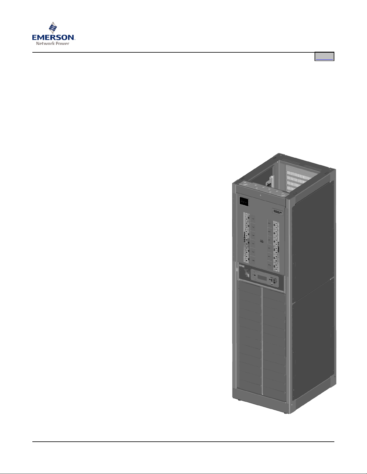
Description: -48V DC @ up to 16,800 amperes Power System.
This power system is designed to power a load while charging a positive grounded
battery. This power system is capable of operating in a batteryless installation or off
battery for maintenance purposes. This power system is designed for operation with the
positive output grounded.
The N
Bay), and 801
system containing rectifiers, intelligent control, metering, monitoring, and distribution.
This power system consists of the following components.
• Power Bays
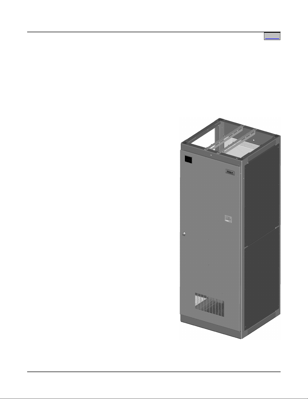
• Distribution Bays
SAG582140001
System Application Guide
Spec. No. 582140001 (Model 801
ETSURE™ 801NLDB (208V Input Power Bay), 801NLEB (380V/480V Input Power
NL-B (Distribution Bay) DC Power System is a complete integrated power
The system consists of one (1) Primary Power Bay and up to six (6) Secondary
Power Bays.
Each Power Bay can be equipped with up
to twenty-four (24) Rectifier Modules.
Each Power Bay contains a Monitor and
Control Panel. In the Primary Power Bay,
this panel houses the Meter-Control-Alarm
(MCA) assembly. This panel in the Primary
Power Bay also houses the optional LMS
Main CPU circuit card of the integrated
LMS Monitoring System. In a Secondary
Power Bay, this panel can be equipped
with an optional LMS Expansion CPU
circuit card. (The optional LMS Monitoring
System provides a higher level of
monitoring and controlling capabilities to
the power system.)
The Monitor and Control Panel in both
Primary and Secondary Power Bays
contain a seven-slot card cage to house
MCA alarm relay circuit cards, MCA
input/output (I/O) circuit cards, and optional
LMS I/O circuit cards. (If a Secondary
Power Bay is to be equipped with optional
LMS I/O circuit cards, it must also be
equipped with the LMS Expansion CPU
circuit card.)
The system consists of one (1) to eight (8)
Distribution Bays.
Each Distribution Bay provides four (4)
distribution buses.
Each distribution bus accepts a choice of
218-type circuit breakers and TPL-type
fuses.
A Distribution Bay may also be equipped
with an optional distribution panel which
accepts a choice of TPS/TLS-type
NLDB, 801NLEB, 801NL-B)
Issue AN, June 4, 2014
Power Bay
Page 1 of 115
This document is property of Emerson Network Power, Energy Systems, North America, Inc. and contains confidential and proprietary information owned by Emerson Network Power, Energy
Systems, North America, Inc. Any copying, use, or disclosure of it without the written permission of Emerson Network Power, Energy Systems, North America, Inc. is strictly prohibited.
Page 2
SAG582140001 System Application Guide
Home
Issue AN, June 4, 2014 Spec. No. 582140001 (Model 801
NLDB, 801NLEB, 801NL-B)
fuseholders or Bullet Nose-type circuit breakers.
• Rectifier Modules
The Rectifier Modules provide load power, battery float current, and battery recharge
current during normal operating conditions.
• MCA (Meter-Control-Alarm)
The MCA controls the operation of the Rectifier Modules and provides power system
control, metering, monitoring, and alarm functions.
MCA Local Control Panel: This panel is located on the front of the Primary Power
Bay and contains a keypad, display, and indicators for local MCA user interface.
MCA Relay Circuit Card: Each MCA relay circuit card provides six (6) sets of
Form-C relay contacts for customer external alarms. These relays are user
programmable for various power system alarms. Up to sixteen (16) MCA relay circuit
cards can be installed in the Primary
and Secondary Power Bays. The
Primary Power Bay is factory
equipped with two (2) MCA relay
circuit cards.
MCA I/O Circuit Cards: The MCA
I/O circuit cards provide analog
inputs/outputs and binary inputs. Up
to sixteen (16) MCA I/O circuit cards
can be installed in the Primary and
Secondary Power Bays.
• Optional Integrated
LMS Monitoring System
The LMS Monitoring System consists
of an LMS Main CPU circuit card,
optional LMS Expansion CPU circuit
cards, optional LMS I/O circuit cards,
optional LMS Expansion Cabinet,
and optional LMS Expansion
Assemblies.
The LMS Main CPU circuit card is
mounted in the Primary Power Bay.
Each Secondary Power Bay that is to
be equipped with optional LMS I/O
circuit cards must contain an LMS
Expansion CPU circuit card. LMS
Expansion Cabinets and LMS
Expansion Assemblies are available
that mount into customer racks and
equipment.
The LMS Monitoring System is
factory integrated within each Power
Bay, and requires no additional
customer interconnections within the
Power Bay. Simple cable
connections between Power and
Distribution Bays complete the
interbay connections required.
Separate analog, binary, and relay circuit cards do not have to be supplied for power
system monitoring. Analog, binary, relay, and temperature circuit cards can be
Distribution Bay
Page 2 of 115
This document is property of Emerson Network Power, Energy Systems, North America, Inc. and contains confidential and proprietary information owned by Emerson Network Power, Energy
Systems, North America, Inc. Any copying, use, or disclosure of it without the written permission of Emerson Network Power, Energy Systems, North America, Inc. is strictly prohibited.
Page 3

System Application Guide SAG582140001
Home
Spec. No. 582140001 (Model 801
NLDB, 801NLEB, 801NL-B) Issue AN, June 4, 2014
provided to monitor equipment external to the power system.
The LMS input circuit cards monitor a variety of analog, binary, and
temperature points external to the system. An LMS relay output circuit card is also
available which provides programmable relays. These relays may be used for
external alarms, or to control other equipment.
The LMS Monitoring System can be accessed via a local port, a modem port (when
optional modem is ordered), an optional TL1 port, and an Ethernet port (for Telnet
access, optional Web access, optional SNMP access, optional TL1 access, and
Email alarm reporting).
The LMS Monitoring System collects data from the power system and the input circuit
cards monitoring external points. The data collected is used for alarm processing
and reporting, and to provide statistics.
The LMS Monitoring System is capable of reporting alarm conditions to a remote
terminal, pager, Email address, via SNMP traps over Ethernet when the SNMP
option is ordered, or via TL1 (over Ethernet) when the 'TL1 over Ethernet' option is
ordered. TL1 is also available via a serial connection in 'direct mode'. For remote
terminal or pager notification, the LMS Main CPU circuit card must be equipped with
the optional modem. Two types of alarm reporting mechanisms are provided,
System Alarm Reporting and Individual User Alarm Reporting.
Refer to SAG586505000 for further LMS information. The SAG can be accessed via
the CD (Electronic Documentation Package) furnished with your system.
• Applications
ETSURE™ 801NLDB and 801NLEB is capable of interfacing with Vortex
The N
®
Power
Systems (VPS).
ETSURE™ 801NLDB and 801NLEB is capable of interfacing with legacy power
The N
systems.
Refer to the wiring diagrams in the Installation Instructions (Section 6016). Refer
also to Lists 64, 65, 66, and 67.
Page 3 of 115
This document is property of Emerson Network Power, Energy Systems, North America, Inc. and contains confidential and proprietary information owned by Emerson Network Power, Energy
Systems, North America, Inc. Any copying, use, or disclosure of it without the written permission of Emerson Network Power, Energy Systems, North America, Inc. is strictly prohibited.
Page 4

SAG582140001 System Application Guide
Home
Issue AN, June 4, 2014 Spec. No. 582140001 (Model 801
NLDB, 801NLEB, 801NL-B)
Family: N
ETSURE™
Spec. No.: 582140001
Model: 801
801
801
NLDB (208V Input Power Bay)
NLEB (380V/480V Input Power Bay)
NL-B (Distribution Bay)
Input Voltage Nominal 380/480 volts AC, three phase, 50/60 Hz, with an operating
range of 260 to 530 volts. Acceptable input frequency range is 45 to 65
Hz.
or
Nominal 208 volts AC, three phase, 50/60 Hz, with an operating range of
176 to 264 volts. Acceptable input frequency range is 45 to 65 Hz.
Output Voltage: -48 Volts DC
Output Capacity:
System: 16,800 Amperes, maximum
(Other configurations are available. For higher amperage configurations,
contact Emerson Network Power.)
Power Bay: 2400 Amperes, maximum
Rectifier Module: 100A / -48V
Distribution Bay: 6000 Amperes, maximum
Distribution Bus: 1500 Amperes, maximum
(four Distribution Buses
per Distribution Bay)
Optional Distribution Panel: 500 Amperes, maximum
(Bullet Nose Circuit
Breakers and/or TLS/TPS
Fuses) (one optional
Distribution Panel per
Distribution Bay)
Agency Approval: Model 801
NL-B (Distribution Bay): Listed UL 1801, NEBS
Model 801NLEB (Power Bay): Listed UL 1950, NEBS
Model 801NLDB (Power Bay):
Lists (All): Listed UL 1950
Lists (0B, 05, 13, 21, 50,
63, 64, 65, 66, 67, 70, 71): NEBS
Framework Type: Seismic Rated (Zone 4) Box Framework
Power Bay:
Width: 24.375 Inches
Depth: 30 Inches
Height: 84 Inches
Access: Front and Rear Access for Installation and Maintenance, Front for
Operation.
Distribution Bay:
Width: 31.375 Inches
Depth: 30 Inches
Height: 84 Inches
Access: Front and Rear Access for Installation and Maintenance, Front for
Operation.
Maximum Number of
Power Bays per System: 7
Page 4 of 115
This document is property of Emerson Network Power, Energy Systems, North America, Inc. and contains confidential and proprietary information owned by Emerson Network Power, Energy
Systems, North America, Inc. Any copying, use, or disclosure of it without the written permission of Emerson Network Power, Energy Systems, North America, Inc. is strictly prohibited.
Page 5

System Application Guide SAG582140001
Home
Spec. No. 582140001 (Model 801
NLDB, 801NLEB, 801NL-B) Issue AN, June 4, 2014
Maximum Number of
Distribution Bays per System: 8
Control: Microprocessor
Color: Gray
Environment: 0°C to +40°C (+32°F to +104°F)
Configurations: Plant is designed for centralized configuration with customer supplied
Main Battery Termination Bars (MBTB’s). Emerson Network Power
Services has standard MBTB’S in 4000, 6000, 10000, and 16000
ampere capacities. The ultimate plant capacity is determined by the
capacity of the MBTB’S.
Plant can be configured for distribution applications by bay-to-bay
cabling up to 9600 amperes.
Page 5 of 115
This document is property of Emerson Network Power, Energy Systems, North America, Inc. and contains confidential and proprietary information owned by Emerson Network Power, Energy
Systems, North America, Inc. Any copying, use, or disclosure of it without the written permission of Emerson Network Power, Energy Systems, North America, Inc. is strictly prohibited.
Page 6
SAG582140001 System Application Guide
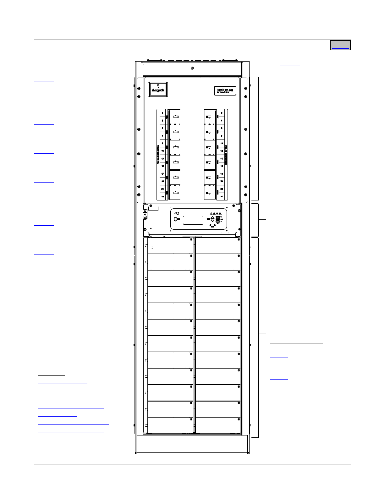
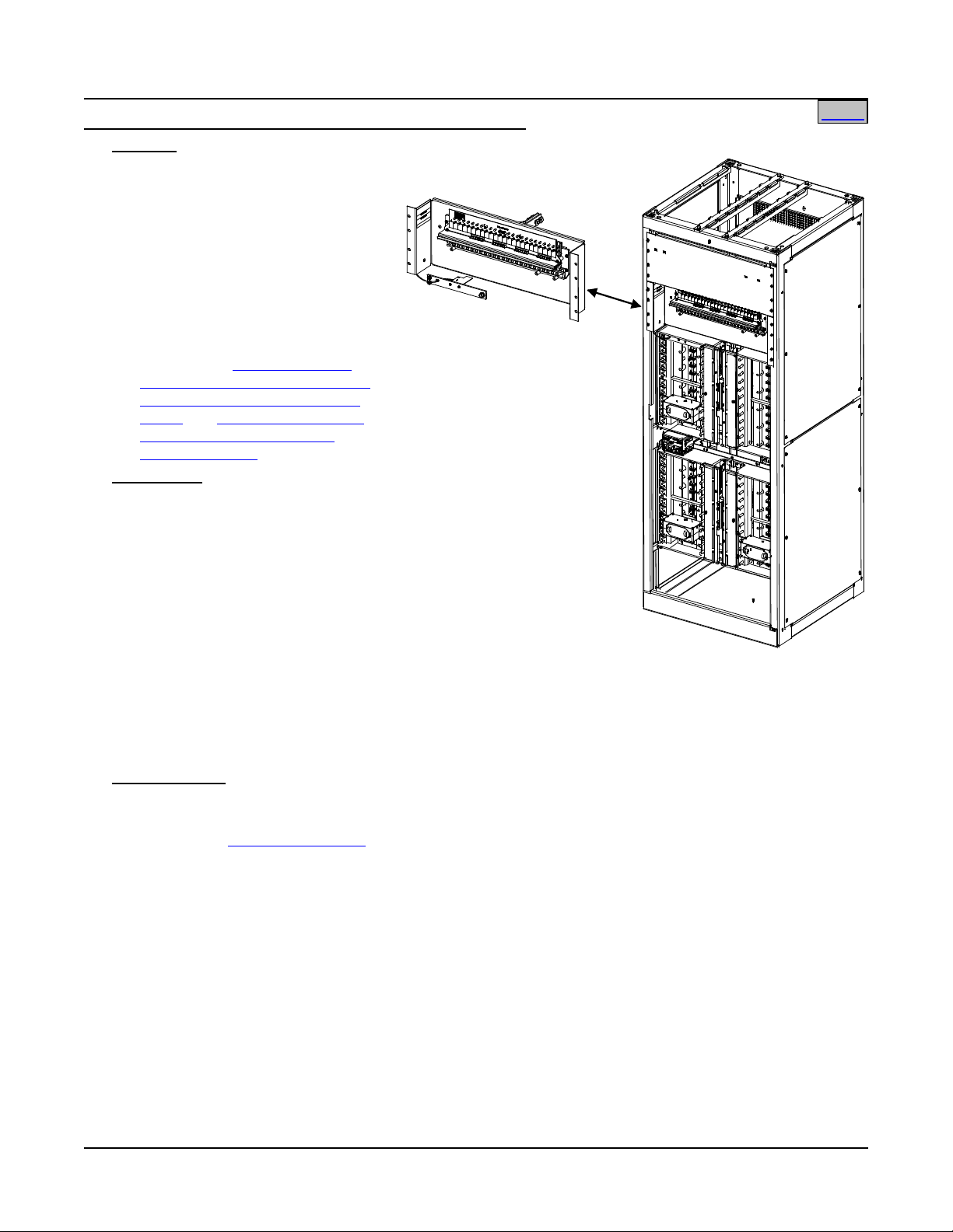
List 04: Primary Power Bay
List 05:
List 06:
List 12:
List 13:
List 14
(see Monitor and
Control Diagram)
Front View
See Also
Home
AC Input Termination Panel
and Optional AC Input
Breakers
List 0A: 380/480VAC
List 0B
Rectifier Module
Mounting Positions
List 21
List 22
Issue AN, June 4, 2014 Spec. No. 582140001 (Model 801
NLDB, 801NLEB, 801NL-B)
582140001 Power Bays
Plant Input
(2 AC Input Feeds)
(Includes Circuit
Breakers, One per Two
Rectifier Modules)
Primary Power Bay
(12 or 24 AC Input
Feeds)
Primary Power Bay
(6 Input Feeds)
480V only.
Secondary Power Bay
(2 AC Input Feeds)
(Includes Circuit
Breakers, One per Two
Rectifier Modules)
Secondary Power Bay
(12 or 24 AC Input
Feeds)
: Secondary Power Bay
(6 Input Feeds)
480V only.
: 208VAC Plant
Input
System Overview
Table of Contents
List Descriptions
Accessory Descriptions
Specifications
Physical Size Information
Related Documentation
This document is property of Emerson Network Power, Energy Systems, North America, Inc. and contains confidential and proprietary information owned by Emerson Network Power, Energy
Systems, North America, Inc. Any copying, use, or disclosure of it without the written permission of Emerson Network Power, Energy Systems, North America, Inc. is strictly prohibited.
Page 6 of 115
: Rectifier Module
(208VAC Input)
: Rectifier Module
(380/480VAC
Input)
Page 7
System Application Guide SAG582140001
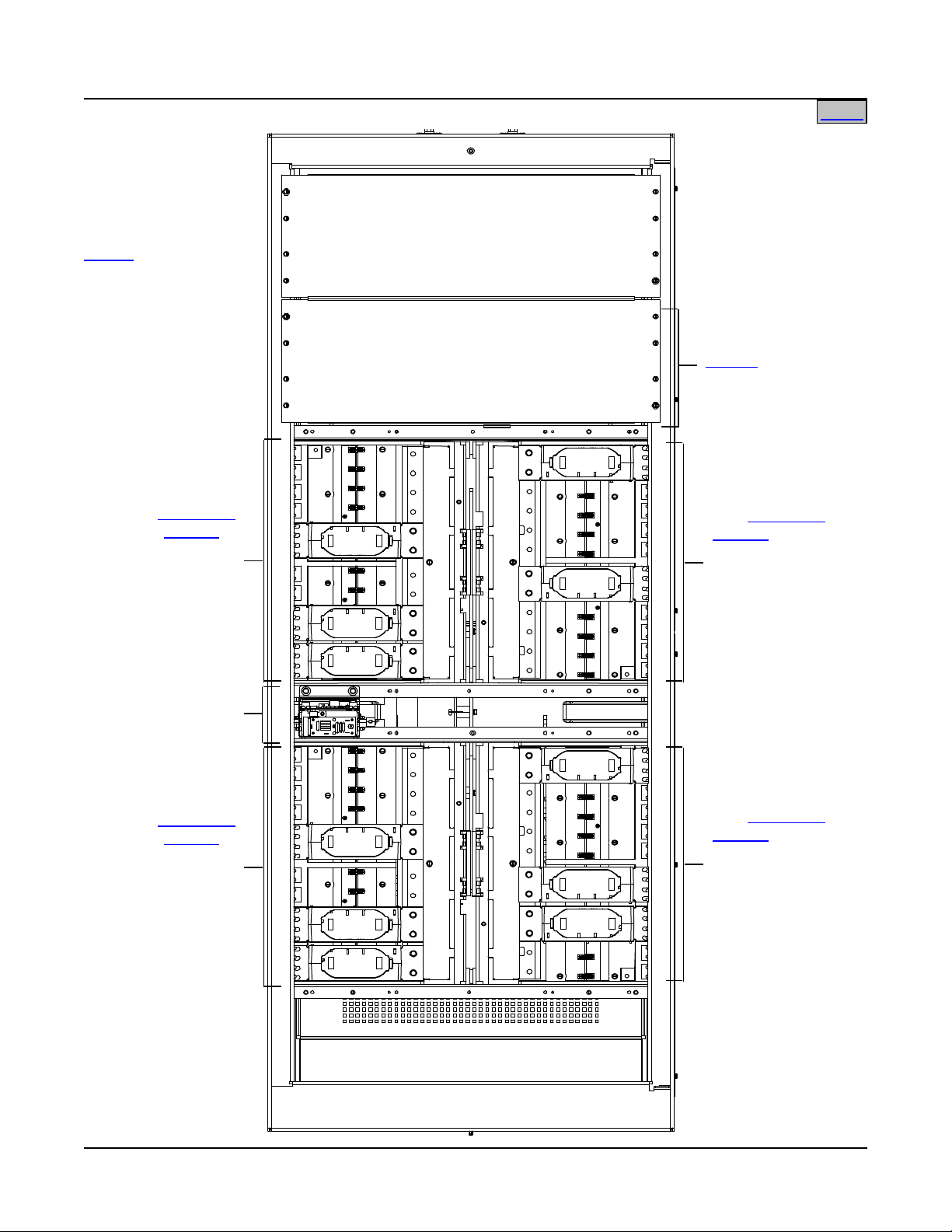
List 16: Distribution Bay
Distribution Bus
(see
Devices
ACCESSORY
DESCRIPTIONS
Section for
distribution
options)
Distribution Bus
(see
Devices
ACCESSORY
DESCRIPTIONS
Section for
distribution
options)
Distribution Bus
Distribution
in
ACCESSORY
DESCRIPTIONS
Section for
distribution
options)
Distribution Bus
Distribution
in
ACCESSORY
DESCRIPTIONS
Section for
ion
options)
(see Monitor and
Control Diagram)
Blank Panel
or
List 0C:
Front View
Home
Spec. No. 582140001 (Model 801
NLDB, 801NLEB, 801NL-B) Issue AN, June 4, 2014
582140001 Distribution Bays
Bullet
Fuse/Circuit
Breaker Panel
(see
(see
Devices
distribut
Devices
Distribution
in
Distribution
in
This document is property of Emerson Network Power, Energy Systems, North America, Inc. and contains confidential and proprietary information owned by Emerson Network Power, Energy
Systems, North America, Inc. Any copying, use, or disclosure of it without the written permission of Emerson Network Power, Energy Systems, North America, Inc. is strictly prohibited.
Page 7 of 115
Front door removed in
illustration for clarity.
Page 8
SAG582140001 System Application Guide
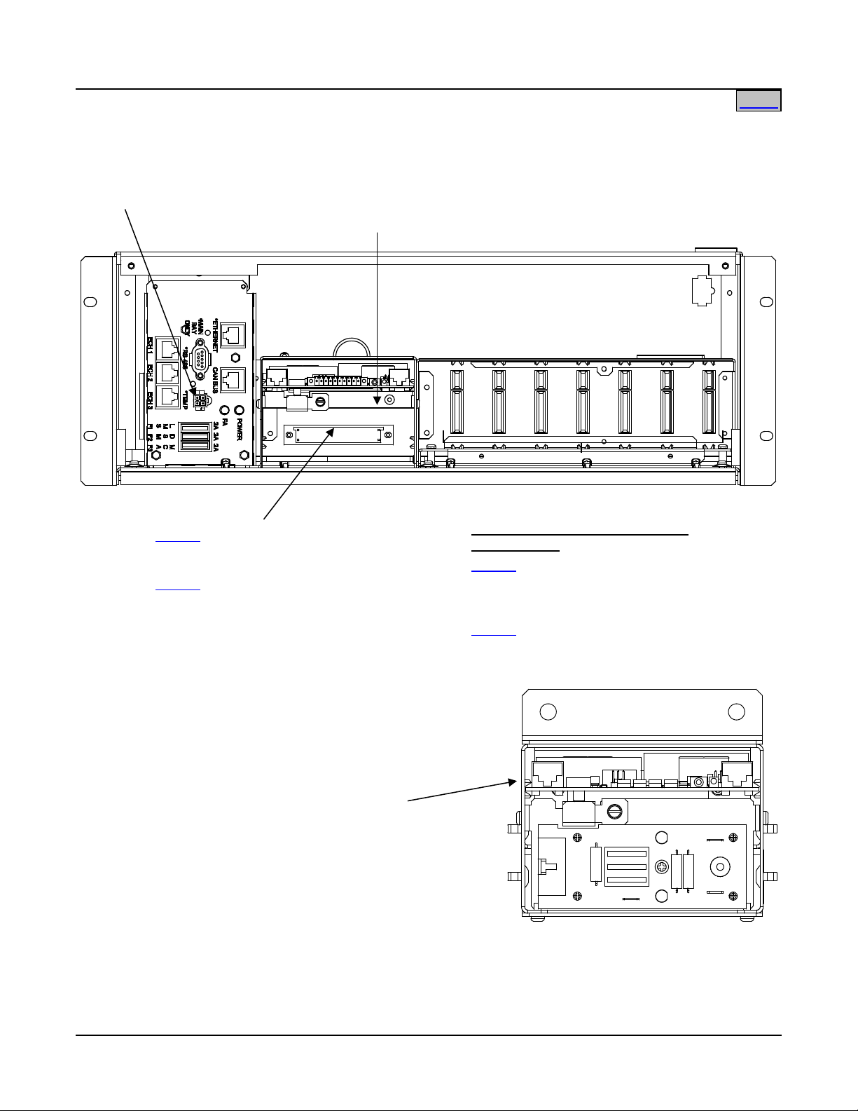
List 50: Optional LMS Main CPU
List 63:
Refer to SAG586505000
for additional LMS options.
Available MCA Input/Output (I/O)
Circuit Cards
List 70:
List 71:
P/O List 4 and 5: MCA Circuit Card
P/O List 12 and 13:
P/O Lists 16:
ROUTER Circuit Card
Front View
Battery Charge Temperature
Compensation Probe Connector
Home
Issue AN, June 4, 2014 Spec. No. 582140001 (Model 801
NLDB, 801NLEB, 801NL-B)
582140001 Power Bays Monitor and Control Diagram
(Primary Bay)
ROUTER Circuit Card
(Secondary Bay)
5821400
01
Circuit Card
or
Optional LMS Expansion
CPU Circuit Card
MCA Customer Alarm
MCA Analog Input/Output
Relay Circuit Card (Six [6]
Form-C Contacts)
and Binary Input Circuit
Card
Distribution Bays Monitor and Control Diagram
This document is property of Emerson Network Power, Energy Systems, North America, Inc. and contains confidential and proprietary information owned by Emerson Network Power, Energy
Systems, North America, Inc. Any copying, use, or disclosure of it without the written permission of Emerson Network Power, Energy Systems, North America, Inc. is strictly prohibited.
Page 8 of 115
Page 9

System Application Guide SAG582140001
Spec. No. 582140001 (Model 801
NLDB, 801NLEB, 801NL-B) Issue AN, June 4, 2014
TABLE OF CONTENTS
System
Overview
Picture
List
Descriptions
Accessory
Descriptions
Specifications
Physical Size
Information
Related
Documentation
SYSTEM OVERVIEW ................................................................................................................................................. 1
582140001 Power Bays ....................................................................................................................................... 6
582140001 Distribution Bays .............................................................................................................................. 7
582140001 Power Bays Monitor and Control Diagram .................................................................................... 8
582140001 Distribution Bays Monitor and Control Diagram .......................................................................... 8
TABLE OF CONTENTS ............................................................................................................................................. 9
LIST DESCRIPTIONS .............................................................................................................................................. 11
List 0A: 380/480VAC Plant Input Voltage ..................................................................................................... 11
List 0B: 208VAC Plant Input Voltage ............................................................................................................ 11
List 04: Primary Power Bay (2 AC Input Feeds) ........................................................................................... 11
List 05: Primary Power Bay (12 or 24 AC Input Feeds) ................................................................................ 12
List 06: Primary Power Bay (6 AC Input Feeds) ........................................................................................... 12
List 12: Secondary Power Bay (2 AC Input Feeds) ...................................................................................... 13
List 13: Secondary Power Bay (12 or 24 AC Input Feeds) ........................................................................... 14
List 14: Secondary Power Bay (6 AC Input Feeds) ...................................................................................... 15
List 16: Distribution Bay ................................................................................................................................ 15
List 21: Rectifier Module, 208V Input ............................................................................................................ 16
List 22: Rectifier Module, 380/480V Input ..................................................................................................... 16
List 24: Rectifier Module, 380/480V Input ..................................................................................................... 16
List 50: Optional LMS Main CPU Circuit Card (Primary Power Bay) ............................................................ 16
List 63: Optional LMS Expansion CPU Circuit Card (Secondary Power Bays) ............................................ 17
List 64: Interface Kit to a Spec. No. 582121900 Power System equipped with a DGU ................................ 17
List 65: Interface Kit to a Spec. No. 582121901 Power System equipped with an LMS1000 ...................... 18
List 66: Interface Kit to a Vortex Power System without a DGU or LMS1000 .............................................. 18
List 67: Interface Kit to a Model 1231H Legacy Power System with 1-8 Rectifiers ...................................... 18
List 70: Additional MCA Six (6) Output Form-C Relay Circuit Card .............................................................. 19
List 71: MCA I/O Circuit Card P/N 524550 .................................................................................................... 19
List 0C: 24 Position Bullet-Nose Circuit Breaker/Fuse Panel ....................................................................... 20
ACCESSORY DESCRIPTIONS ............................................................................................................................... 21
Seismic Anchor Kit, P/N 545387 ...................................................................................................................... 21
Seismic Anchor Isolation Kit, P/N 545388 ...................................................................................................... 21
Main Battery Termination Bars (MBTB’s) ....................................................................................................... 21
Distribution Device and Load Lug Locations ................................................................................................. 21
Distribution Devices .......................................................................................................................................... 25
218 Circuit Breaker Assemblies ..................................................................................................................... 25
TPL Fuses and Fuseholder Assemblies ........................................................................................................ 29
Bullet Nose-Type Circuit Breakers and Bullet Nose-Type Fuseholders e/w TLS/TPS Fuses ....................... 32
Optional Bullet Nose-Type 10-Position GMT Fuse Module for List C ............................................................ 37
Replacement Alarm, Reference, and Control Fuses ...................................................................................... 38
Fuseblock Located in Bay’s Left Center ........................................................................................................ 38
Input and Alarm Fuse on Optional Bullet Nose-Type 10-Position GMT Fuse Module, P/N 509128 ............. 39
Wiring Components .......................................................................................................................................... 40
Load Distribution Wire Sizes and Lugs Selection (Distribution Bay) ............................................................. 40
Power Bay DC Output Cable Sizes and Lugs Selection ................................................................................ 44
Distribution Bay DC Input Cable Sizes and Lugs Selection ........................................................................... 46
Power Bay Frame Grounding Wire Sizes and Lugs Selection ...................................................................... 48
Distribution Bay Frame Grounding Wire Sizes and Lugs Selection ............................................................... 49
Page 9 of 115
This document is property of Emerson Network Power, Energy Systems, North America, Inc. and contains confidential and proprietary information owned by Emerson Network Power, Energy
Systems, North America, Inc. Any copying, use, or disclosure of it without the written permission of Emerson Network Power, Energy Systems, North America, Inc. is strictly prohibited.
Page 10

SAG582140001 System Application Guide
Issue AN, June 4, 2014 Spec. No. 582140001 (Model 801
NLDB, 801NLEB, 801NL-B)
AC Input (12 or 24 AC Input Feeds) Wire and Conduit Sizes, Branch Circuit Protection, and Lugs
Selection Lists 5 and 13 ................................................................................................................................. 50
AC Input (6 AC Input Feeds) Wire and Conduit Sizes, Branch Circuit Protection, and Lugs
Selection Lists 6 and 14 ................................................................................................................................. 53
AC Input (2 AC Input Feeds) Wire and Conduit Sizes, Branch Circuit Protection, and Lugs
Selection Lists 4 and 12 ................................................................................................................................ 59
External Alarm, Reference, and Control Wire Sizes - Power Bays ............................................................... 62
Optional Battery Charge Temperature Compensation Probe for Digital Compensation ........................... 63
Replacement/Additional MCA Network Cable ................................................................................................ 64
Replacement/Additional LMS Network Cable ................................................................................................. 64
Replacement Modules and Circuit Cards ....................................................................................................... 65
SPECIFICATIONS .................................................................................................................................................... 66
1. System ........................................................................................................................................................... 66
1.1 DC Operating Voltage .............................................................................................................................. 66
1.2 Environmental Ratings ............................................................................................................................. 66
1.3 Compliance Information ........................................................................................................................... 67
1.4 Local Controls and Indicators ................................................................................................................... 67
2. Distribution Bay ............................................................................................................................................ 67
2.1 DC Ratings ............................................................................................................................................... 67
3. Rectifier Module (Model R48-5800, Spec. No. 1R485800) ......................................................................... 68
3.1 DC Output Ratings ................................................................................................................................... 68
3.2 AC Input Ratings ...................................................................................................................................... 71
3.3 Environmental Ratings ............................................................................................................................. 71
3.4 Standard Features .................................................................................................................................... 74
4. Rectifier Module (Model R48-5800L, Spec. No. 1R485800L)..................................................................... 78
4.1 DC Output Ratings ................................................................................................................................... 78
4.2 AC Input Ratings ...................................................................................................................................... 81
4.3 Environmental Ratings ............................................................................................................................. 81
4.4 Standard Features .................................................................................................................................... 84
5. Rectifier Module (Model R48-5800E Spec. No. 1R485800E) ..................................................................... 88
5.1 DC Output Ratings ................................................................................................................................... 88
5.2 AC Input Ratings ...................................................................................................................................... 91
5.3 Environmental Ratings ............................................................................................................................. 91
5.4 Standard Features .................................................................................................................................... 94
6. MCA ................................................................................................................................................................ 98
6.1 Standard Features .................................................................................................................................... 98
7. Optional LMS Monitoring System ............................................................................................................. 109
PHYSICAL SIZE INFORMATION .......................................................................................................................... 110
Floor Hole Drilling Pattern Dimensions - Power Bays ................................................................................. 110
Floor Hole Drilling Pattern Dimensions - Distribution Bays ....................................................................... 110
Overall Dimensions - Primary and Secondary Power Bays ........................................................................ 111
Overall Dimensions - Distribution Bays ........................................................................................................ 112
Overall Dimensions – Optional Battery Charge Digital Temperature Compensation Probes P/N
107021 (25 feet) and P/N 106824 (100 feet) ................................................................................................... 113
RELATED DOCUMENTATION .............................................................................................................................. 114
REVISION RECORD .............................................................................................................................................. 115
Page 10 of 115
This document is property of Emerson Network Power, Energy Systems, North America, Inc. and contains confidential and proprietary information owned by Emerson Network Power, Energy
Systems, North America, Inc. Any copying, use, or disclosure of it without the written permission of Emerson Network Power, Energy Systems, North America, Inc. is strictly prohibited.
Page 11

System Application Guide SAG582140001
Home
Spec. No. 582140001 (Model 801
NLDB, 801NLEB, 801NL-B) Issue AN, June 4, 2014
LIST DESCRIPTIONS
List 0A: 380/480VAC Plant Input Voltage
Features
♦ Specifies 380/480VAC Plant Input Voltage.
List 0B: 208VAC Plant Input Voltage
Features
♦ Specifies 208VAC Plant Input Voltage.
List 04: Primary Power Bay (2 AC Input Feeds)
Features
♦ Provides common equipment for one (1) Power Bay rated for up to 2400 amperes.
♦ Mounted in a 7'0"H x 24.375"W x 30"D seismic rated (Zone 4) box framework.
♦ Provides twenty-four (24) Rectifier Module mounting positions.
♦ Provides an AC input termination panel that accepts two (2) AC input branch circuits, one (1) per twelve
(12) Rectifier Module mounting positions. A 60A AC input circuit breaker rated for 65kA interrupting
capacity is provided for each pair of rectifier positions in the List B Bay. A 30A AC input circuit breaker
rated for 22kA interrupting capacity is provided for each pair of rectifier positions in the List A Bay.
♦ Provides the MCA Assembly and Local MCA Control Panel.
♦ Provides mounting for optional LMS Main CPU circuit card.
♦ Provides a seven-slot card cage for mounting MCA customer alarm relay circuit cards, MCA I/O circuit
cards, and/or optional LMS I/O circuit cards. Two (2) MCA customer alarm relay circuit cards furnished,
providing twelve (12) Form-C relay contacts
♦ Side cover panels are factory installed on both sides of the bay.
Restrictions
Only one (1) Primary Bay per power system required.
Ordering Notes
1) Specify List A (380/480VAC Input) or List B (208VAC Input).
2) Order up to twenty-four (24) Rectifiers Modules per bay per List 21 (208VAC Input) or List 22
(380/480VAC Input).
3) Order additional MCA customer alarm relay circuit card(s) as required per List 70, and optional MCA I/O
circuit cards per List 71.
4) Order a Battery Charge Temperature Compensation Probe as required per Optional Battery Charge
Temperature Compensation Probe for Digital Compensation in the ACCESSORY DESCRIPTIONS
section.
5) Order optional LMS Monitor and LMS options as required per List 50, and SAG586505000.
6) Order “Power Bay DC Output” lugs as required per Power Bay DC Output Cable Sizes and Lugs
Selection in the ACCESSORY DESCRIPTIONS section.
7) Order “AC Input” lugs as required per AC Input (Dual AC Input Feeds) Wire and Conduit Sizes, Branch
Circuit Protection, and Lugs Selection in the ACCESSORY DESCRIPTIONS section.
8) Order “Power Bay Frame Grounding” lugs as required per Power Bay Frame Grounding Wire Sizes and
Lugs Selection in the ACCESSORY DESCRIPTIONS section.
9) If the system is to be connected to an existing system with an MCA, refer to List 64, 65, 66, and 67.
Page 11 of 115
This document is property of Emerson Network Power, Energy Systems, North America, Inc. and contains confidential and proprietary information owned by Emerson Network Power, Energy
Systems, North America, Inc. Any copying, use, or disclosure of it without the written permission of Emerson Network Power, Energy Systems, North America, Inc. is strictly prohibited.
Page 12

SAG582140001 System Application Guide
Home
Issue AN, June 4, 2014 Spec. No. 582140001 (Model 801
NLDB, 801NLEB, 801NL-B)
List 05: Primary Power Bay (12 or 24 AC Input Feeds)
Features
♦ Provides common equipment for one (1) Power Bay rated for up to 2400 amperes.
♦ Mounted in a 7'0"H x 24.375"W x 30"D seismic rated (Zone 4) box framework.
♦ Provides twenty-four (24) Rectifier Module mounting positions.
♦ Provides an AC input termination panel that accepts twenty-four (24) AC input branch circuits [one (1) per
Rectifier Module mounting position] or twelve (12) AC input branch circuits [one (1) per two Rectifier
Module mounting positions]. The bay ships with the 12 Feed option installed.
♦ Provides the MCA Assembly and Local MCA Control Panel.
♦ Provides mounting for optional LMS Main CPU circuit card.
♦ Provides a seven-slot card cage for mounting MCA customer alarm relay circuit cards, MCA I/O circuit
cards, and/or optional LMS I/O circuit cards. Two (2) MCA customer alarm relay circuit cards furnished,
providing twelve (12) Form-C relay contacts.
♦ Side cover panels are factory installed on both sides of the bay.
Restrictions
Only one (1) Primary Bay per power system required.
Ordering Notes
1) Specify List A (380/480VAC Input) or List B (208VAC Input).
2) Order up to twenty-four (24) Rectifiers Modules per bay per List 21 (208VAC Input) or List 22
(380/480VAC Input).
3) Order additional MCA customer alarm relay circuit card(s) as required per List 70, and optional MCA I/O
circuit cards per List 71.
4) Order a Battery Charge Temperature Compensation Probe as required per Optional Battery Charge
Temperature Compensation Probe for Digital Compensation in the ACCESSORY DESCRIPTIONS
section.
5) Order optional LMS Monitor and LMS options as required per List 50, and SAG586505000.
6) Order “Power Bay DC Output” lugs as required per Power Bay DC Output Cable Sizes and Lugs
Selection in the ACCESSORY DESCRIPTIONS section.
7) Order “AC Input Ground” lugs as required per AC Input (Individual/Twin AC Input Feeds) Wire and
Conduit Sizes, Branch Circuit Protection, and Lugs Selection in the ACCESSORY DESCRIPTIONS
section.
8) Order “Power Bay Frame Grounding” lugs as required per Power Bay Frame Grounding Wire Sizes and
Lugs Selection in the ACCESSORY DESCRIPTIONS section.
9) If the system is to be connected to an existing system with an MCA, refer to List 64, 65, 66, and 67.
List 06: Primary Power Bay (6 AC Input Feeds)
Features
♦ Provides common equipment for one (1) Power Bay rated for up to 2400 amperes.
♦ Mounted in a 7'0"H x 24.375"W x 30"D seismic rated (Zone 4) box framework.
♦ Provides twenty-four (24) Rectifier Module mounting positions.
♦ Provides an AC input termination panel that accepts six (6) AC input branch circuits [one (1) per four
Rectifier Module mounting positions].
♦ Provides the MCA Assembly and Local MCA Control Panel.
♦ Provides mounting for optional LMS Main CPU circuit card.
♦ Provides a seven-slot card cage for mounting MCA customer alarm relay circuit cards, MCA I/O circuit
cards, and/or optional LMS I/O circuit cards. Two (2) MCA customer alarm relay circuit cards furnished,
providing twelve (12) Form-C relay contacts.
Page 12 of 115
This document is property of Emerson Network Power, Energy Systems, North America, Inc. and contains confidential and proprietary information owned by Emerson Network Power, Energy
Systems, North America, Inc. Any copying, use, or disclosure of it without the written permission of Emerson Network Power, Energy Systems, North America, Inc. is strictly prohibited.
Page 13

System Application Guide SAG582140001
Home
Spec. No. 582140001 (Model 801
NLDB, 801NLEB, 801NL-B) Issue AN, June 4, 2014
♦ Side cover panels are factory installed on both sides of the bay.
Restrictions
Only one (1) Primary Bay per power system required. 480V only.
Ordering Notes
1) Specify List A (480VAC Input).
2) Order up to twenty-four (24) Rectifiers Modules per bay per List 22 (380/480VAC Input).
3) Order additional MCA customer alarm relay circuit card(s) as required per List 70, and optional MCA I/O
circuit cards per List 71.
4) Order a Battery Charge Temperature Compensation Probe as required per Optional Battery Charge
Temperature Compensation Probe for Digital Compensation in the ACCESSORY DESCRIPTIONS
section.
5) Order optional LMS Monitor and LMS options as required per List 50, and SAG586505000.
6) Order “Power Bay DC Output” lugs as required per Power Bay DC Output Cable Sizes and Lugs
Selection in the ACCESSORY DESCRIPTIONS section.
7) Order “AC Input Ground” lugs as required per AC Input Wire and Conduit Sizes, Branch Circuit
Protection, and Lugs Selection in the ACCESSORY DESCRIPTIONS section.
8) Order “Power Bay Frame Grounding” lugs as required per Power Bay Frame Grounding Wire Sizes and
Lugs Selection in the ACCESSORY DESCRIPTIONS section.
9) If the system is to be connected to an existing system with an MCA, refer to List 64, 65, 66, and 67.
List 12: Secondary Power Bay (2 AC Input Feeds)
Features
♦ Provides common equipment for one (1) Power Bay rated for up to 2400 amperes.
♦ Mounted in a 7'0"H x 24.375"W x 30"D seismic rated (Zone 4) box framework.
♦ Provides twenty-four (24) Rectifier Module mounting positions.
♦ Provides an AC input termination panel that accepts two (2) AC input branch circuits, one (1) per twelve
(12) Rectifier Module mounting positions. A 60A AC input circuit breaker rated for 65kA interrupting
capacity is provided for each pair of rectifier positions in the List B Bay. A 30A AC input circuit breaker
rated for 22kA interrupting capacity is provided for each pair of rectifier positions in the List A Bay.
♦ Includes a Router Assembly for bay communication to the MCA in the Primary Power Bay.
♦ Provides mounting for optional LMS Expansion CPU circuit card.
♦ Provides a seven-slot card cage for mounting MCA customer alarm relay circuit cards, MCA I/O circuit
cards, and/or optional LMS I/O circuit cards.
♦ MCA Network bay interconnect cable provided (Qty. 1 P/N 514642).
Ordering Notes
1) Specify List A (380/480VAC Input) or List B (208VAC Input).
2) Order up to twenty-four (24) Rectifiers Modules per bay per List 21 (208VAC Input) or List 22
(380/480VAC Input).
3) Order additional MCA customer alarm relay circuit card(s) as required per List 70, and optional MCA I/O
circuit cards per List 71.
4) Order optional LMS Expansion CPU circuit card and LMS options as required per List 63, and
SAG586505000. Also order additional LMS Network cables as required per Replacement/Additional LMS
Network Cables.
5) Order “Power Bay DC Output” lugs as required per Power Bay DC Output Cable Sizes and Lugs
Selection in the ACCESSORY DESCRIPTIONS section.
6) Order “AC Input” lugs as required per AC Input (Dual AC Input Feeds) Wire and Conduit Sizes, Branch
Circuit Protection, and Lugs Selection in the ACCESSORY DESCRIPTIONS section.
Page 13 of 115
This document is property of Emerson Network Power, Energy Systems, North America, Inc. and contains confidential and proprietary information owned by Emerson Network Power, Energy
Systems, North America, Inc. Any copying, use, or disclosure of it without the written permission of Emerson Network Power, Energy Systems, North America, Inc. is strictly prohibited.
Page 14

SAG582140001 System Application Guide
Home Home
Issue AN, June 4, 2014 Spec. No. 582140001 (Model 801
NLDB, 801NLEB, 801NL-B)
7) Order “Power Bay Frame Grounding” lugs as required per Power Bay Frame Grounding Wire
Sizes and Lugs Selection in the ACCESSORY DESCRIPTIONS section.
8) If a different length LMS and/or MCA Network cable is required, order per Replacement/Additional LMS
Network Cables and/or Replacement/Additional MCA Network Cables. Refer to the Installation
Instructions (Section 6016) for Network cabling requirements.
9) Side cover panels are not provided. When bays are placed next to each other, the side cover panels
from the ‘inside’ side of the Primary Power Bay are moved to the ‘outside’ side of the last Secondary
Power Bay. In installations where a Secondary Power Bay is placed by itself, order (4) P/N 535092 side
cover panels.
List 13: Secondary Power Bay (12 or 24 AC Input Feeds)
Features
♦ Provides common equipment for one (1) Power Bay rated for up to 2400 amperes.
♦ Mounted in a 7'0"H x 24.375"W x 30"D seismic rated (Zone 4) box framework.
♦ Provides twenty-four (24) Rectifier Module mounting positions.
♦ Provides an AC input termination panel that accepts twenty-four (24) AC input branch circuits [one (1) per
Rectifier Module mounting position] or twelve (12) AC input branch circuits [one (1) per two Rectifier
Module mounting positions]. The bay ships with the 12 Feed option installed.
♦ Includes a Router Assembly for bay communication to the MCA in the Primary Power Bay.
♦ Provides mounting for optional LMS Expansion CPU circuit card.
♦ Provides a seven-slot card cage for mounting MCA customer alarm relay circuit cards, MCA I/O circuit
cards, and/or optional LMS I/O circuit cards.
♦ MCA Network bay interconnect cable provided (Qty. 1 P/N 514642).
Ordering Notes
1) Specify List A (380/480VAC Input) or List B (208VAC Input).
2) Order up to twenty-four (24) Rectifiers Modules per bay per List 21 (208VAC Input) or List 22
(380/480VAC Input).
3) Order additional MCA customer alarm relay circuit card(s) as required per List 70, and optional MCA I/O
circuit cards per List 71.
4) Order optional LMS Expansion CPU circuit card and LMS options as required per List 63, and
SAG586505000. Also order additional LMS Network cables as required per Replacement/Additional LMS
Network Cables.
5) Order “Power Bay DC Output” lugs as required per Power Bay DC Output Cable Sizes and Lugs
Selection in the ACCESSORY DESCRIPTIONS section.
6) Order “AC Input Ground” lugs as required per AC Input (Individual/Twin AC Input Feeds) Wire and
Conduit Sizes, Branch Circuit Protection, and Lugs Selection in the ACCESSORY DESCRIPTIONS
section.
7) Order “Power Bay Frame Grounding” lugs as required per Power Bay Frame Grounding Wire Sizes and
Lugs Selection in the ACCESSORY DESCRIPTIONS section.
8) If a different length LMS and/or MCA Network cable is required, order per Replacement/Additional LMS
Network Cables and/or Replacement/Additional MCA Network Cables. Refer to the Installation
Instructions (Section 6016) for Network cabling requirements.
9) Side cover panels are not provided. When bays are placed next to each other, the side cover panels
from the ‘inside’ side of the Primary Power Bay are moved to the ‘outside’ side of the last Secondary
Power Bay. In installations where a Secondary Power Bay is placed by itself, order (4) P/N 535092 side
cover panels.
Page 14 of 115
This document is property of Emerson Network Power, Energy Systems, North America, Inc. and contains confidential and proprietary information owned by Emerson Network Power, Energy
Systems, North America, Inc. Any copying, use, or disclosure of it without the written permission of Emerson Network Power, Energy Systems, North America, Inc. is strictly prohibited.
Page 15

System Application Guide SAG582140001
Home
Spec. No. 582140001 (Model 801
NLDB, 801NLEB, 801NL-B) Issue AN, June 4, 2014
List 14: Secondary Power Bay (6 AC Input Feeds)
Features
♦ Provides common equipment for one (1) Power Bay rated for up to 2400 amperes.
♦ Mounted in a 7'0"H x 24.375"W x 30"D seismic rated (Zone 4) box framework.
♦ Provides twenty-four (24) Rectifier Module mounting positions.
♦ Provides an AC input termination panel that accepts six (6) AC input branch circuits [one (1) per four
Rectifier Module mounting positions].
♦ Includes a Router Assembly for bay communication to the MCA in the Primary Power Bay.
♦ Provides mounting for optional LMS Expansion CPU circuit card.
♦ Provides a seven-slot card cage for mounting MCA customer alarm relay circuit cards, MCA I/O circuit
cards, and/or optional LMS I/O circuit cards.
♦ MCA Network bay interconnect cable provided (Qty. 1 P/N 514642).
Restrictions
480V only.
Ordering Notes
1) Specify List A (480VAC Input).
2) Order up to twenty-four (24) Rectifiers Modules per bay per List 22 (380/480VAC Input).
3) Order additional MCA customer alarm relay circuit card(s) as required per List 70, and optional MCA I/O
circuit cards per List 71.
4) Order optional LMS Expansion CPU circuit card and LMS options as required per List 63, and
SAG586505000. Also order additional LMS Network cables as required per Replacement/Additional LMS
Network Cables.
5) Order “Power Bay DC Output” lugs as required per Power Bay DC Output Cable Sizes and Lugs
Selection in the ACCESSORY DESCRIPTIONS section.
6) Order “AC Input Ground” lugs as required per AC Input (Individual/Twin AC Input Feeds) Wire and
Conduit Sizes, Branch Circuit Protection, and Lugs Selection in the ACCESSORY DESCRIPTIONS
section.
7) Order “Power Bay Frame Grounding” lugs as required per Power Bay Frame Grounding Wire Sizes and
Lugs Selection in the ACCESSORY DESCRIPTIONS section.
8) If a different length LMS and/or MCA Network cable is required, order per Replacement/Additional LMS
Network Cables and/or Replacement/Additional MCA Network Cables. Refer to the Installation
Instructions (Section 6016) for Network cabling requirements.
9) Side cover panels are not provided. When bays are placed next to each other, the side cover panels
from the ‘inside’ side of the Primary Power Bay are moved to the ‘outside’ side of the last Secondary
Power Bay. In installations where a Secondary Power Bay is placed by itself, order (4) P/N 535092 side
cover panels.
List 16: Distribution Bay
Features
♦ Provides common equipment for one (1) Distribution Bay rated for up to 6000 amperes.
♦ Mounted in a 7'0"H x 31.375"W x 30"D seismic rated (Zone 4) box framework.
♦ Provides forty-eight (48) distribution device mounting positions.
♦ Provides four (4) buses of distribution. Each bus contains an MCA monitoring circuit card; which can be
set for no group designation, Group A designation, or Group B designation.
♦ Includes a Router Assembly for bay communication to the MCA in the Primary Power Bay.
♦ MCA Network bay interconnect cable provided (P/N 514644).
Page 15 of 115
This document is property of Emerson Network Power, Energy Systems, North America, Inc. and contains confidential and proprietary information owned by Emerson Network Power, Energy
Systems, North America, Inc. Any copying, use, or disclosure of it without the written permission of Emerson Network Power, Energy Systems, North America, Inc. is strictly prohibited.
Page 16

SAG582140001 System Application Guide
Home
Issue AN, June 4, 2014 Spec. No. 582140001 (Model 801
NLDB, 801NLEB, 801NL-B)
Ordering Notes
1) Order distribution fuse and/or circuit breaker devices as required per Distribution Devices in the
ACCESSORY DESCRIPTIONS section.
2) Order load distribution lugs as required per Load Distribution Wire Sizes and Lugs Selection (Distribution
Bay) in the ACCESSORY DESCRIPTIONS section.
3) Order “Distribution Bay DC Input” lugs as required per Distribution Bay DC Input Cable Sizes and Lugs
Selection in the ACCESSORY DESCRIPTIONS section.
4) Order “Distribution Bay Frame Grounding” lugs as required per Distribution Bay Frame Grounding Wire
Sizes and Lugs Selection in the ACCESSORY DESCRIPTIONS section.
5) Order one (1) “Twenty-Four (24) Position Bullet-Nose Circuit Breaker/Fuse Panel” per Distribution Bay as
required per List C.
6) If a different length MCA Network cable is required, order per Replacement/Additional MCA Network
Cables. Refer to the Installation Instructions (Section 6016) for Network cabling requirements.
7) Side cover panels are factory installed on one side of the bay. In installations where a Distribution Bay is
placed by itself, order (2) P/N 528633 side cover panels for the other side.
List 21: Rectifier Module, 208V Input
Features
♦ Model R48-5800L, Spec. No. 1R485800L, 100A / 48 volt rectifier module.
Restrictions
For use in List B bays only.
Ordering Notes
1) Order List 21 Rectifier Modules as required. Each Power Bay holds up to twenty-four (24) Rectifier
Modules.
List 22: Rectifier Module, 380/480V Input
Features
♦ Model R48-5800, Spec. No. 1R485800, 100A / 48 volt rectifier module.
Restrictions
For use in List A bays only.
Ordering Notes
1) Order List 22 Rectifier Modules as required. Each Power Bay holds up to twenty-four (24) Rectifier
Modules.
List 24: Rectifier Module, 380/480V Input
Features
♦ Model R48-5800e, Spec. No. 1R485800e, 100A / 48 volt rectifier module.
Restrictions
For use in List A bays only. Requires that the system Router software is version 2.5.0.0 or higher.
Ordering Notes
Order List 24 Rectifier Modules as required. Each Power Bay holds up to twenty-four (24) Rectifier Modules.
List 50: Optional LMS Main CPU Circuit Card (Primary Power Bay)
Features
♦ Provides the LMS Monitoring System.
♦ Refer to SAG586505000 for further information.
Page 16 of 115
This document is property of Emerson Network Power, Energy Systems, North America, Inc. and contains confidential and proprietary information owned by Emerson Network Power, Energy
Systems, North America, Inc. Any copying, use, or disclosure of it without the written permission of Emerson Network Power, Energy Systems, North America, Inc. is strictly prohibited.
Page 17

System Application Guide SAG582140001
Home
Spec. No. 582140001 (Model 801
NLDB, 801NLEB, 801NL-B) Issue AN, June 4, 2014
Restrictions
The LMS Monitoring System Main CPU circuit card is mounted in the Primary Power Bay only.
Ordering Notes
1) Order the optional LMS Monitor if increased monitoring capabilities are required. Order the LMS Main
CPU circuit card (List 50) for the Primary Power Bay. Order the LMS Expansion CPU circuit card (List 63)
for Secondary Power Bays that are to be equipped with LMS I/O circuit cards.
2) Order additional LMS Network cables as required per Replacement/Additional LMS Network Cables.
Note that an LMS Network cable is factory provided with List 63.
3) This List option only provides the LMS CPU circuit card for the Primary Power Bay, additional LMS
options must be ordered separately per SAG586505000.
List 63: Optional LMS Expansion CPU Circuit Card (Secondary Power Bays)
Features
♦ Allows LMS I/O cards to be installed in Secondary Power Bays.
♦ LMS Network bay interconnect cable provided (Qty. 1 P/N 514639).
Restrictions
The LMS Monitoring System Expansion CPU circuit cards are mounted in Secondary Power Bays (required
only if LMS I/O circuit cards are to be installed in the same bay).
Ordering Notes
1) Order the LMS Expansion CPU circuit card for Secondary Power Bays that are to be equipped with LMS
I/O circuit cards.
List 64: Interface Kit to a Spec. No. 582121900 Power System equipped with a DGU
Features
♦ Provides the following...
LMS Dual MCA Interface Software Option
LMS Gateway Software Option
P/N 526843 50’ LMS Dual MCA Option Cable
P/N 548009 50’ LMS Gateway Port Cable
♦ LMS Dual MCA Interface Software Option enables the Spec. No. 582140001 Power System to be
integrated with an existing Power System. Specifically, List 64 allows the MCA in Spec. No. 582140001
to interface with the MCA in a Spec. No. 582121900 via the LMS in Spec. No. 582140001. Refer to the
LMS documentation for further information.
♦ LMS Gateway Software Option allows the LMS to emulate a “dumb” RS-232 asynchronous terminal
interface. Specifically, List 64 enables user input through either a local or remote LMS port to be directed
to a DGU connected to the LMS Gateway port. Refer to the LMS documentation for further information.
Restrictions
Operation of Energy Management is disabled with this option installed.
The Gateway port is provided via the port located on the front of the LMS CPU circuit card installed in the
Spec. No. 582140001 Primary Bay.
Ordering Notes
1) Order as required.
Page 17 of 115
This document is property of Emerson Network Power, Energy Systems, North America, Inc. and contains confidential and proprietary information owned by Emerson Network Power, Energy
Systems, North America, Inc. Any copying, use, or disclosure of it without the written permission of Emerson Network Power, Energy Systems, North America, Inc. is strictly prohibited.
Page 18

SAG582140001 System Application Guide
Home
Issue AN, June 4, 2014 Spec. No. 582140001 (Model 801
NLDB, 801NLEB, 801NL-B)
List 65: Interface Kit to a Spec. No. 582121901 Power System equipped with an LMS1000
Features
♦ Provides the following...
LMS Dual MCA Interface Software Option
P/N 506153 LMS Expansion CPU Card
P/N 514641 150’ Echelon Cable
P/N 526843 50’ LMS Dual MCA Option Cable
♦ LMS Dual MCA Interface Software Option enables the Spec. No. 582140001 Power System to be
integrated with an existing Power System. Specifically, List 65 allows the MCA in Spec. No. 582140001
to interface with the MCA in Spec. No. 582121901 via the LMS in Spec. No. 582140001. Refer to the
LMS documentation for further information.
Restrictions
Operation of Energy Management is disabled with this option installed.
The Main LMS CPU card in 582121901 must be replaced with the Expansion LMS CPU card (P/N 506153)
provided with List 65.
Ordering Notes
1) Order as required.
List 66: Interface Kit to a Vortex Power System without a DGU or LMS1000
Features
♦ Provides the following...
LMS Dual MCA Interface Software Option
P/N 526843 50’ LMS Dual MCA Option Cable
♦ LMS Dual MCA Interface Software Option enables the Spec. No. 582140001 Power System to be
integrated with an existing Power System. Specifically, List 66 allows the MCA in Spec. No. 582140001
to interface with the MCA in a Vortex Power System via the LMS in Spec. No. 582140001. Refer to the
LMS documentation for further information.
Restrictions
Operation of Energy Management is disabled with this option installed.
Ordering Notes
1) Order as required.
List 67: Interface Kit to a Model 1231H Legacy Power System with 1-8 Rectifiers
Features
♦ Provides the following...
LMS Gateway Software Option
P/N 548009 50’ LMS Gateway Port Cable
Two (2) P/N 506336 LMS 4-Input Universal Analog Cards
One (1) P/N 506334 LMS 8-Input Binary Card
♦ LMS Gateway Software Option allows the LMS to emulate a “dumb” RS-232 asynchronous terminal
interface. Specifically, List 67 enables user input through either a local or remote LMS port to be directed
to a DGU (in the legacy plant) connected to the LMS Gateway port. Refer to the LMS documentation for
further information.
♦ The analog and binary DGU I/O cards provide monitoring of the legacy system’s rectifiers
Restrictions
LMS Channels must be configured.
Ordering Notes
1) Order as required.
Page 18 of 115
This document is property of Emerson Network Power, Energy Systems, North America, Inc. and contains confidential and proprietary information owned by Emerson Network Power, Energy
Systems, North America, Inc. Any copying, use, or disclosure of it without the written permission of Emerson Network Power, Energy Systems, North America, Inc. is strictly prohibited.
Page 19

System Application Guide SAG582140001
Home
Spec. No. 582140001 (Model 801
NLDB, 801NLEB, 801NL-B) Issue AN, June 4, 2014
List 70: Additional MCA Six (6) Output Form-C Relay Circuit Card
Features
♦ Provides six relays each with one set of Form-C relay contacts.
♦ These relays are used for alarm applications and can be programmed by the user.
♦ Refer to the "Specifications" section of this document for further information.
♦ Plugs into any slot in 7-position card cage in Primary and Secondary Power Bays.
♦ User maps relay closure to any or multiple programmable alarm functions.
Restrictions
Relay contacts rated for 2A at 30 volts DC.
The system may contain up to 16 MCA Relay circuit cards.
Ordering Notes
1) Order one (1) List 70 relay circuit card for every six (6) customer relay contacts to be provided by the
MCA.
List 71: MCA I/O Circuit Card P/N 524550
Features
♦ Provides 1 analog input, 1 analog output (for remote plant output current monitoring), and 4 binary inputs.
♦ Refer to the "Specifications" section of this document for further information.
♦ Plugs into any slot in 7-position card cage in Primary and Secondary Power Bays.
Restrictions
The system may contain up to 16 MCA I/O circuit cards.
Only one (1) P/N 524550 card can be installed per bay.
Analog input and output rating = 0-50mv DC.
Binary input rating = dry contact.
Analog inputs should be protected by a 49.9 ohm resistor.
Recommended to use current limiting resistors to protect binary input wiring.
Ordering Notes
1) Order optional MCA I/O circuit cards as required.
2) Use of the “Alternate Current Limit” feature requires that an MCA I/O circuit card be installed.
Page 19 of 115
This document is property of Emerson Network Power, Energy Systems, North America, Inc. and contains confidential and proprietary information owned by Emerson Network Power, Energy
Systems, North America, Inc. Any copying, use, or disclosure of it without the written permission of Emerson Network Power, Energy Systems, North America, Inc. is strictly prohibited.
Page 20
SAG582140001 System Application Guide
Home
Optional List C
Bullet Nose Device Panel
Front door removed in
illustration for clarity.
Issue AN, June 4, 2014 Spec. No. 582140001 (Model 801
NLDB, 801NLEB, 801NL-B)
List 0C: 24 Position Bullet-Nose Circuit Breaker/Fuse Panel
Features
♦ Provides twenty-four (24) Bullet
Nose Device positions.
♦ Accepts a choice of TLS/TPS-type
fuseholders, Bullet Nose-Type
circuit breakers, or Bullet NoseType GMT Fuse Modules.
♦ The List C Fuse/Circuit Breaker
Panel is equipped with one (1)
shunt for all distribution positions for
MCA load current measurements.
♦ Refer also to Bullet Nose-Type
Circuit Breakers and Bullet NoseType Fuseholders e/w TLS/TPS
Fuses and Optional Bullet Nose-
Type 10-Position GMT Fuse
Module for List C.
Restrictions
Each Distribution Bay can be equipped
with only one (1) List C panel.
The List C Circuit Breaker/Fuse Panel
requires distribution position #12 in the
Bus #1 Distribution Panel.
Current monitoring for the List C
Fuse/Circuit Breaker Panel is for the
complete panel. Circuit Breakers
and/or fuses are not individually
monitored.
When installed, the bay can be loaded with up to (47) 218 Circuit Breakers or (23) TPL Fuses and (24) Bullet
Nose Circuit Breakers or TLS/TPS Fuses.
The List C Circuit Breaker/Fuse Panel is rated for a maximum continuous load of 500 amps.
The total load combination of List C and Distribution Panel #1 cannot exceed 1500A.
Ordering Notes
1) Order as required.
2) Also order distribution fuses, circuit breakers, and/or Bullet Nose-Type 10-Position GMT Fuse Modules as
required per Distribution Devices in the ACCESSORY DESCRIPTIONS section.
This document is property of Emerson Network Power, Energy Systems, North America, Inc. and contains confidential and proprietary information owned by Emerson Network Power, Energy
Systems, North America, Inc. Any copying, use, or disclosure of it without the written permission of Emerson Network Power, Energy Systems, North America, Inc. is strictly prohibited.
Page 20 of 115
Page 21

System Application Guide SAG582140001
Home
Spec. No. 582140001 (Model 801
NLDB, 801NLEB, 801NL-B) Issue AN, June 4, 2014
ACCESSORY DESCRIPTIONS
Seismic Anchor Kit, P/N 545387
Features
Provides four (4) Relay Rack Seismic Mounting Anchors, P/N 216821200.
Ordering Notes
1) Order Seismic Anchor Kit, P/N 545387, as required.
Seismic Anchor Isolation Kit, P/N 545388
Features
Provides four (4) bushings, P/N 124866 (one per seismic anchor) and one (1) insulator, P/N 112490.
Ordering Notes
1) Order Seismic Isolation Anchor Kit, P/N 545388, as required.
Main Battery Termination Bars (MBTB’s)
Plant is designed for centralized configuration with customer supplied Main Battery Termination Bars
(MBTB’s). Emerson Network Power Services has standard MBTB’S in 4000, 6000, 10000, and 16000
ampere capacities. The ultimate plant capacity is determined by the capacity of the MBTB’S. Refer to the
EA3434-41xx Series MBTB’s drawings.
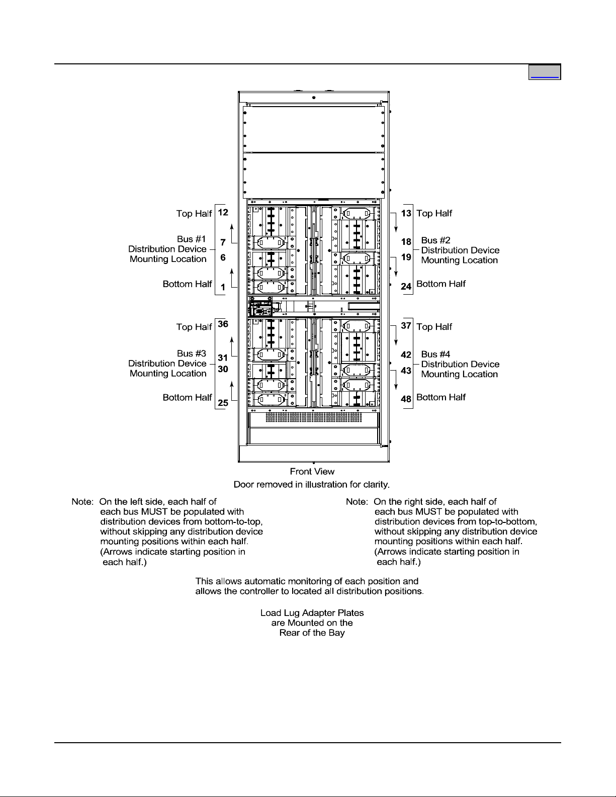
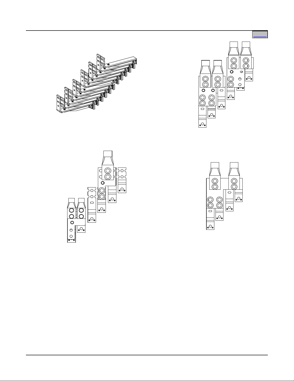
Distribution Device and Load Lug Locations
Each Distribution Bay has four (4) distribution buses. Each distribution bus has twelve (12) fuse/circuit
breaker device mounting positions. Note that the various fuse/circuit breaker devices require different number
of mounting positions, as detailed in the following sections. Note also that each distribution bus is divided into
half, and each half MUST be populated with distribution devices as shown in the following illustration, without
skipping any distribution device mounting positions within each half. This allows automatic monitoring of each
position and allows the controller to located all distribution positions. The load side of each fuse/circuit
breaker mounting position is bused to the rear of the bay. Each fuse/circuit breaker device requires a load lug
adapter plate kit that mounts to the appropriate load side busbars at the rear of the bay (except 1-pole
devices). Load return leads are terminated outside the bay to customer provided return busbars. See
following illustration.
Page 21 of 115
This document is property of Emerson Network Power, Energy Systems, North America, Inc. and contains confidential and proprietary information owned by Emerson Network Power, Energy
Systems, North America, Inc. Any copying, use, or disclosure of it without the written permission of Emerson Network Power, Energy Systems, North America, Inc. is strictly prohibited.
Page 22
SAG582140001 System Application Guide
Home
Issue AN, June 4, 2014 Spec. No. 582140001 (Model 801
NLDB, 801NLEB, 801NL-B)
Page 22 of 115
This document is property of Emerson Network Power, Energy Systems, North America, Inc. and contains confidential and proprietary information owned by Emerson Network Power, Energy
Systems, North America, Inc. Any copying, use, or disclosure of it without the written permission of Emerson Network Power, Energy Systems, North America, Inc. is strictly prohibited.
Page 23
System Application Guide SAG582140001
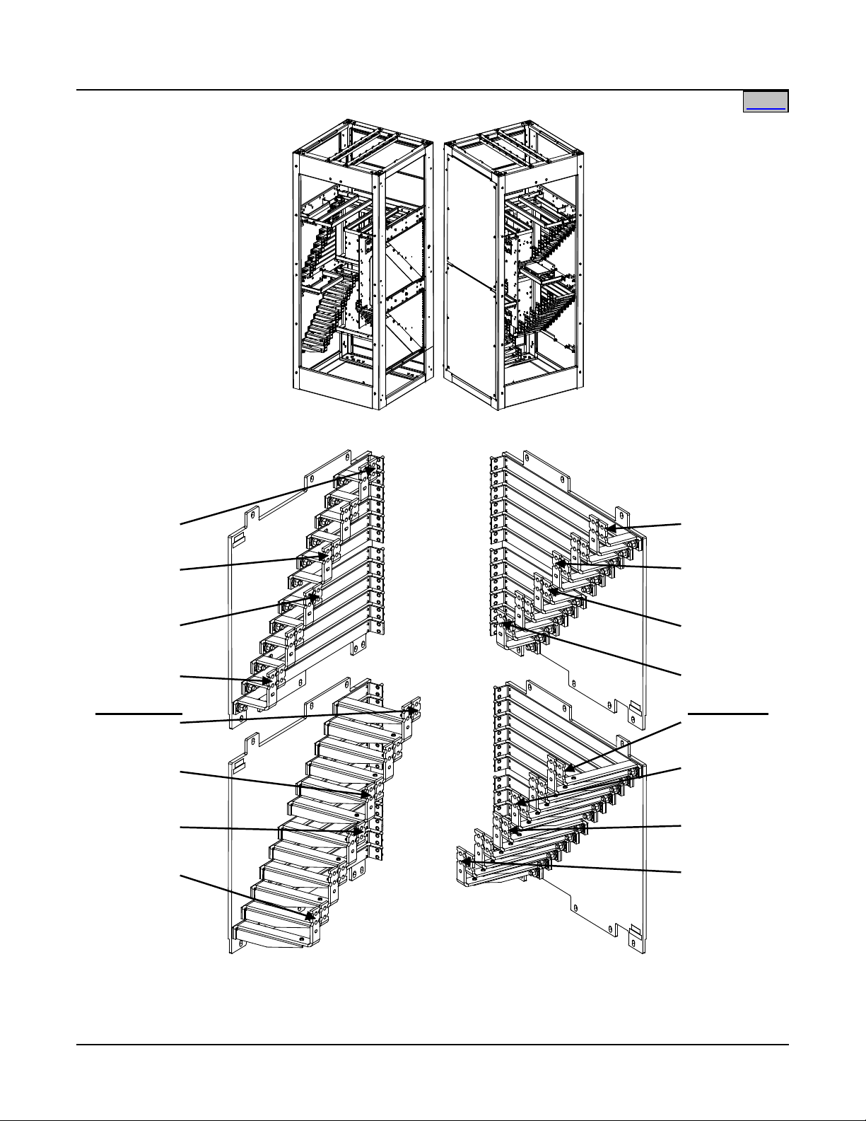
to Distribution:
Bus #2
Position #24
to Distribution:
Bus #2
Position #19
to Distribution:
Bus #2
Position #18
to Distribution:
Bus #2
Position #13
to Distribution:
Bus #4
Position #48
to Distribution:
Bus #4
Position #43
to Distribution:
Bus #4
Position #42
to Distribution:
Bus #4
Position #37
to Distribution:
Bus #1
Position #1
to Distribution:
Bus #1
Position #6
to Distribution:
Bus #1
Position #7
to Distribution:
Bus #1
Position #12
to Distribution:
Bus #3
Position #25
to Distribution:
Bus #3
Position #30
to Distribution:
Bus #3
Position #31
to Distribution:
Bus #3
Position #36
Rear cover panels removed in illustration for clarity.
Rear View
Rear View
Home
Spec. No. 582140001 (Model 801
NLDB, 801NLEB, 801NL-B) Issue AN, June 4, 2014
Page 23 of 115
This document is property of Emerson Network Power, Energy Systems, North America, Inc. and contains confidential and proprietary information owned by Emerson Network Power, Energy
Systems, North America, Inc. Any copying, use, or disclosure of it without the written permission of Emerson Network Power, Energy Systems, North America, Inc. is strictly prohibited.
Page 24
SAG582140001 System Application Guide
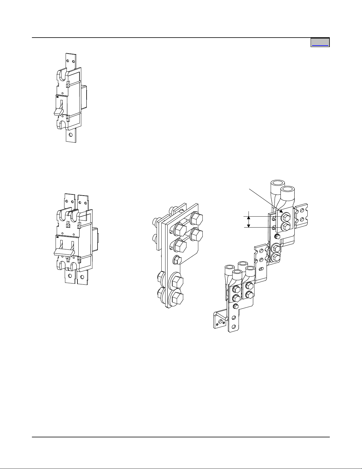
Notes:
1. Lug adapter accepts a maximum of (2) 750 kcmil or (4) 350 kcmil lugs.
2. Lug adapter accepts a maximum of (4) 750 kcmil lugs.
3. Lugs are not part of the kit, shown for illustration only.
4. Bay busbars are not part of the kit, shown for illustration only.
5. Two (2) kits shown for illustration of the kit installed on busbars with tops
even with each other and staggered.
6. Maximum lug width (without using an adapter plate) is 1.250 inches.
2-Position
Lug Adapter Kit
P/N 529132
(see Notes 1, 3, 4, 5)
3-Position
Lug Adapter Kit
P/N 529131
(see Notes 2, 3, 4, 5)
4-Position
Lug Adapter Kit
P/N 534420
(see Notes 2, 3, 4)
1-Position Devices
(Load Busbars with NO
Lug Adapters Installed)
(see Note 6)
Home
Issue AN, June 4, 2014 Spec. No. 582140001 (Model 801
NLDB, 801NLEB, 801NL-B)
This document is property of Emerson Network Power, Energy Systems, North America, Inc. and contains confidential and proprietary information owned by Emerson Network Power, Energy
Systems, North America, Inc. Any copying, use, or disclosure of it without the written permission of Emerson Network Power, Energy Systems, North America, Inc. is strictly prohibited.
Page 24 of 115
Page 25

System Application Guide SAG582140001
Home
Spec. No. 582140001 (Model 801
NLDB, 801NLEB, 801NL-B) Issue AN, June 4, 2014
Distribution Devices
See Distribution Device and Load Lug Locations at the beginning of this section for illustrations of distribution
device and load lug mounting locations.
218 Circuit Breaker Assemblies
Features
♦ Each circuit breaker assembly is equipped with a shunt for MCA load current measurements.
♦ Bolts into bay's distribution device mounting positions.
♦ Load lug busbars and adapter plates provide 3/8" clearance holes on 1" centers for installation of
customer provided two-hole lugs.
Restrictions
Load should not exceed 80% of device rating.
Refer to Table 1 for required distribution bus mounting positions.
Each distribution bus is divided into half. Each half MUST be populated with distribution devices as shown in
the illustrations at the beginning of this section, without skipping any distribution device mounting positions
within each half.
Four (4) position devices can only be installed in the 1st four or last four positions within each half of a
distribution bus. This is because the lug adapter plate for four (4) position devices can only be installed in
positions starting with the load busbar tops even with each other (not staggered).
Divide distribution equally between rows.
Refer to the illustrations in this section for lug and wire size restrictions.
Load return leads are terminated outside the bay to customer provided return busbars.
Ordering Notes
1) Order circuit breaker assemblies and load lug adapter kits per Table 1. Load lug adapter kits also contain
the necessary hardware to mount the circuit breakers. For 1-pole circuit breakers, also order circuit
breaker hardware kit P/N 558709. This hardware is used to mount the circuit breaker.
2) See Table 10 for recommended load distribution wire sizes and lugs.
Page 25 of 115
This document is property of Emerson Network Power, Energy Systems, North America, Inc. and contains confidential and proprietary information owned by Emerson Network Power, Energy
Systems, North America, Inc. Any copying, use, or disclosure of it without the written permission of Emerson Network Power, Energy Systems, North America, Inc. is strictly prohibited.
Page 26

SAG582140001 System Application Guide
200 1 1
513774
513775
not required
225 1 1
513776
513777
not required
250 1 1
513778
513779
not required
300 2 2
513780
513781
529132
350 2 2
513782
513783
529132
400 2 2
513784
513785
529132
450 3 3
513786
513787
529131
500 3 3
513788
513789
529131
600 3 3
513790
513791
529131
800 4 4
513792
513793
534420
Home
Issue AN, June 4, 2014 Spec. No. 582140001 (Model 801
NLDB, 801NLEB, 801NL-B)
Circuit Breaker
Ampere
Rating
No.
of
Poles
Required
Distribution Bus
Mounting
Positions
Electrical Trip1
(White Handle)
Part Number
Electrical/
Mechanical Trip
(Black Handle)
Lug Adapter Kit
Part Number
2
(Qty 1)
100 1 1 513766 513767 not required
125 1 1 513768 513769 not required
150 1 1 513770 513771 not required
175 1 1 513772 513773 not required
See Table 10 for recommended load distribution wire sizes and lugs.
Circuit Breaker Alarm Operation:
1
Provides an alarm during an electrical trip condition only.
2
Provides an alarm during an electrical or manual trip condition.
Table 1
218 Circuit Breaker Assemblies
This document is property of Emerson Network Power, Energy Systems, North America, Inc. and contains confidential and proprietary information owned by Emerson Network Power, Energy
Systems, North America, Inc. Any copying, use, or disclosure of it without the written permission of Emerson Network Power, Energy Systems, North America, Inc. is strictly prohibited.
Page 26 of 115
Page 27
System Application Guide SAG582140001
1-Pole 218 Circuit
Breakers Assemblies
2-Pole 218 Circuit
Breaker Assemblies
NO LUG ADAPTER
KIT REQUIRED
Lug Adapter Kit
2-Position
Lug Adapter Kit
P/N 529132
(see Notes 1, 2, 3, 4)
Lug Adapter Kit
3/8" Clearance Hole
1.000"
Notes:
1. Lug adapter accepts a maximum of (2) 750 kcmil or (4) 350 kcmil lugs.
2. Lugs are not part of the kit, shown for illustration only.
3. Bay busbars are not part of the kit, shown for illustration only.
4. Two (2) kits shown for illustration of the kit installed on busbars with tops
even with each other and staggered.
Home
Spec. No. 582140001 (Model 801
NLDB, 801NLEB, 801NL-B) Issue AN, June 4, 2014
This document is property of Emerson Network Power, Energy Systems, North America, Inc. and contains confidential and proprietary information owned by Emerson Network Power, Energy
Systems, North America, Inc. Any copying, use, or disclosure of it without the written permission of Emerson Network Power, Energy Systems, North America, Inc. is strictly prohibited.
Page 27 of 115
Page 28
SAG582140001 System Application Guide
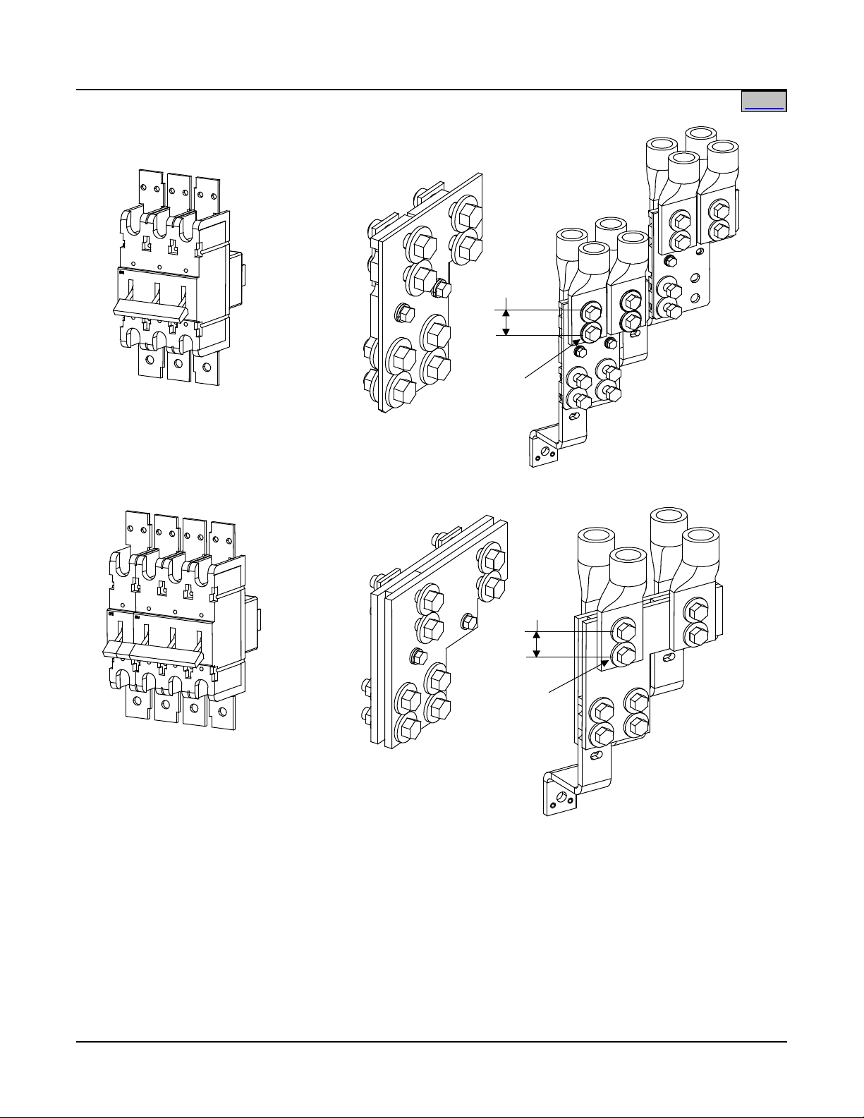
4-Pole 218 Circuit
Breaker Assemblies
3-Pole 218 Circuit
Breaker Assemblies
3-Position
Lug Adapter Kit
P/N 529131
(see Notes 1, 2, 3, 4)
Lug Adapter Kit
3/8"
Clearance
Hole
1.000"
4-Position
Lug Adapter Kit
P/N 534420
(see Notes 1, 2, 3, 5)
Lug Adapter Kit
3/8"
Clearance
Hole
1.000"
Notes:
1. Lug adapter accepts a maximum of (4) 750 kcmil lugs.
2. Lugs are not part of the kit, shown for illustration only.
3. Bay busbars are not part of the kit, shown for illustration only.
4. Two (2) kits shown for illustration of the kit installed on busbars with tops
even with each other and staggered.
5. Can only be installed in positions starting with
busbar tops even with each other (not staggered).
Home
Issue AN, June 4, 2014 Spec. No. 582140001 (Model 801
NLDB, 801NLEB, 801NL-B)
This document is property of Emerson Network Power, Energy Systems, North America, Inc. and contains confidential and proprietary information owned by Emerson Network Power, Energy
Systems, North America, Inc. Any copying, use, or disclosure of it without the written permission of Emerson Network Power, Energy Systems, North America, Inc. is strictly prohibited.
Page 28 of 115
Page 29

System Application Guide SAG582140001
70
2
248251500
514403
529132
80
2
248252000
514403
529132
100
2
248252600
514403
529132
150
2
248253300
514403
529132
200
2
248254000
514403
529132
225
2
248254500
514403
529132
250
2
248255000
514403
529132
300
2
248255700
514403
529132
400
2
248257000
514403
529132
500
2
248258000
514403
529132
600
2
248259000
514403
529132
800
3
102901
514404
529131
Home
Spec. No. 582140001 (Model 801
NLDB, 801NLEB, 801NL-B) Issue AN, June 4, 2014
TPL Fuses and Fuseholder Assemblies
Features
♦ Each fuseholder assembly is equipped with a shunt for MCA load current measurements.
♦ Bolts into bay's distribution device mounting positions.
♦ Load lug busbars and adapter plates provide 3/8" clearance holes on 1" centers for installation of
customer provided two-hole lugs.
Restrictions
Load should not exceed 80% of device rating.
Refer to Table 2 for required distribution bus mounting positions.
Each distribution bus is divided into half. Each half MUST be populated with distribution devices as shown in
the illustrations at the beginning of this section, without skipping any distribution device mounting positions
within each half.
Divide distribution equally between rows.
Refer to the illustrations in this section for lug and wire size restrictions.
Load return leads are terminated outside the bay to customer provided return busbars.
Ordering Notes
1) Order fuses, the appropriate fuseholder assembly for each fuse, and load lug adapter kits per Table 2.
Load lug adapter kits also contain the necessary hardware to mount the fuseholder assembly.
2) For each fuse ordered, also order one (1) P/N 248610301 alarm fuse,
and one (1) P/N 248898700 safety fuse cover.
3) See Table 10 for recommended load distribution wire sizes and lugs.
Ampere
Rating
Required
Distribution
Bus Mounting
Positions
Part Number
Fuse
Fuseholder
Assembly
Lug Adapter Kit
Part Number
For each fuse ordered, also order: one (1) P/N 248610301 alarm fuse
(GMT-18/100A), and one (1) P/N 248898700 safety fuse cover (GMT-X).
See Table 10 for recommended load distribution wire sizes and lugs.
Table 2
TPL Fuses and Fuseholder Assemblies
(Qty. 1)
Page 29 of 115
This document is property of Emerson Network Power, Energy Systems, North America, Inc. and contains confidential and proprietary information owned by Emerson Network Power, Energy
Systems, North America, Inc. Any copying, use, or disclosure of it without the written permission of Emerson Network Power, Energy Systems, North America, Inc. is strictly prohibited.
Page 30
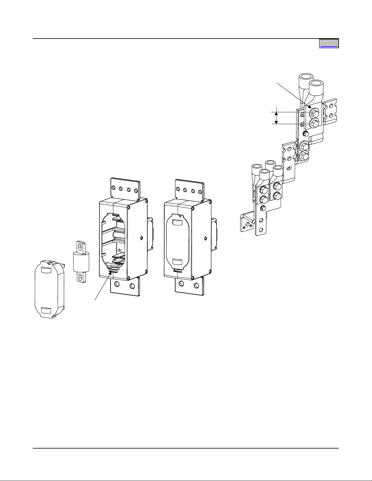
SAG582140001 System Application Guide
Notes:
1. Lug adapter accepts a maximum of (2) 750 kcmil or (4) 350 kcmil lugs.
2. Lugs are not part of the kit, shown for illustration only.
3. Bay busbars are not part of the kit, shown for illustration only.
4. Two (2) kits shown for illustration of the kit installed on busbars with tops
even with each other and staggered.
2-Position
Lug Adapter Kit
P/N 529132
(see Notes 1, 2, 3, 4)
Lug Adapter Kit
3/8" Clearance Hole
1.000"
Fuseholder Assembly
P/N 514403
TPL Fuse
GMT-18/100A
Alarm Fuse
and GMT-X
Safety Fuse Cover
Home
Issue AN, June 4, 2014 Spec. No. 582140001 (Model 801
NLDB, 801NLEB, 801NL-B)
This document is property of Emerson Network Power, Energy Systems, North America, Inc. and contains confidential and proprietary information owned by Emerson Network Power, Energy
Systems, North America, Inc. Any copying, use, or disclosure of it without the written permission of Emerson Network Power, Energy Systems, North America, Inc. is strictly prohibited.
Page 30 of 115
Page 31

System Application Guide SAG582140001
Notes:
1. Lug adapter accepts a maximum of (4) 750 kcmil lugs.
2. Lugs are not part of the kit, shown for illustration only.
3. Bay busbars are not part of the kit, shown for illustration only.
4. Two (2) kits shown for illustration of the kit installed on busbars with tops
even with each other and staggered.
Fuseholder Assembly
P/N 514404
TPL Fuse
GMT-18/100A
Alarm Fuse
and GMT-X
Safety Fuse Cover
3-Position
Lug Adapter Kit
P/N 529131
(see Notes 1, 2, 3, 4)
Lug Adapter Kit
3/8" Clearance Hole
1.000"
Home
Spec. No. 582140001 (Model 801
NLDB, 801NLEB, 801NL-B) Issue AN, June 4, 2014
This document is property of Emerson Network Power, Energy Systems, North America, Inc. and contains confidential and proprietary information owned by Emerson Network Power, Energy
Systems, North America, Inc. Any copying, use, or disclosure of it without the written permission of Emerson Network Power, Energy Systems, North America, Inc. is strictly prohibited.
Page 31 of 115
Page 32

SAG582140001 System Application Guide
Home
Issue AN, June 4, 2014 Spec. No. 582140001 (Model 801
NLDB, 801NLEB, 801NL-B)
Bullet Nose-Type Circuit Breakers and Bullet Nose-Type Fuseholders e/w TLS/TPS Fuses
Features
♦ Installs in the optional List C Fuse/Circuit Breaker Panel.
♦ Load lugs are connected to busbars provided on the List C Fuse/Circuit Breaker Panel. These busbars
provide 1/4-20 threaded holes on 5/8" centers for installation of customer provided two-hole lugs. Load
return leads are terminated outside the bay to customer provided return busbars.
♦ Each circuit breaker (as listed in Table 3 and Table 4) plugs into one, two, or three mounting position(s).
♦ A single fuseholder provides for installation of a 3 to 100 ampere Bussmann TPS-type or Littelfuse
TLS-type fuse (as listed in Table 5). This fuseholder plugs into a single mounting position. This
fuseholder provides a GMT-A alarm type fuse, which operates open to provide an alarm indication if the
associated distribution fuse opens.
Restrictions
Load should not exceed 80% of device rating.
Caution: An overcurrent protective device with a rating of 150 amperes or greater SHALL HAVE an
empty mounting position between it and any other overcurrent protective device within the
List C Fuse/Circuit Breaker Panel.
Maximum size of wire to be connected to a single lug position is 2 AWG.
Maximum lug width is 0.610.
Customer must provide lug mounting bolts and additional hardware.
Bolt length: 3/4”.
Load return leads are terminated outside the bay to customer provided return busbars.
Ordering Notes
1) Order circuit breakers per Table 3 and Table 4.
2) Order fuses per Table 5. For each fuse ordered, also order one (1) P/N 117201 bullet nose type
fuseholder.
3) See Table 9 for recommended load distribution wire sizes and lugs.
Page 32 of 115
This document is property of Emerson Network Power, Energy Systems, North America, Inc. and contains confidential and proprietary information owned by Emerson Network Power, Energy
Systems, North America, Inc. Any copying, use, or disclosure of it without the written permission of Emerson Network Power, Energy Systems, North America, Inc. is strictly prohibited.
Page 33

System Application Guide SAG582140001
Home
Spec. No. 582140001 (Model 801
NLDB, 801NLEB, 801NL-B) Issue AN, June 4, 2014
Part Number
Electrical/
Mechanical Trip
(Black Handle)
Ampere
Rating
Number of Poles
(and mounting positions
required in the List C
Fuse/Circuit Breaker Panel)
Electrical Trip1
(White Handle)
1 1 102272 101596
3 1 102273 101597
5 1 102274 101598
10 1 102275 101599
15 1 102276 101600
20 1 102277 101601
25 1 102278 101602
30 1 102279 101603
35 1 102280 101604
40 1 102281 101605
45 1 121998 121997
50 1 102282 101606
60 1 102283 101607
70 1 102284 101608
75 1 102285 101609
80 1 121996 121995
90 1 138887 138888
100 1 102286 101610
125 2 516991 516838
150 2 516993 516839
175 2 144883 144884
200 2 121831 121832
225 3 144885 144886
250 3 121835 121836
See Table 9 for recommended load distribution wire sizes and lugs.
2
Circuit Breaker Alarm Operation:
1
Provides an alarm during an electrical trip condition only.
2
Provides an alarm during an electrical or manual trip condition.
Table 3
Toggle Handle Bullet Nose-Type Circuit Breakers
Page 33 of 115
This document is property of Emerson Network Power, Energy Systems, North America, Inc. and contains confidential and proprietary information owned by Emerson Network Power, Energy
Systems, North America, Inc. Any copying, use, or disclosure of it without the written permission of Emerson Network Power, Energy Systems, North America, Inc. is strictly prohibited.
Page 34

SAG582140001 System Application Guide
Home
Issue AN, June 4, 2014 Spec. No. 582140001 (Model 801
NLDB, 801NLEB, 801NL-B)
Part Number
Electrical/
Mechanical Trip
(Black Handle)
Ampere
Rating
Number of Poles
(and mounting positions
required in the List C
Fuse/Circuit Breaker Panel)
Electrical Trip1
(White Handle)
1 1 142856 142878
3 1 142857 142879
5 1 142858 142880
10 1 142859 142881
15 1 142861 142882
20 1 142862 142883
25 1 142863 142884
30 1 142864 142885
35 1 142865 142886
40 1 142866 142887
45 1 142867 142888
50 1 142868 142889
60 1 142869 142890
70 1 142870 142891
75 1 142871 142892
80 1 142872 142901
100 1 142873 142902
125 2 142874 142903
150 2 142875 142904
200 2 142876 142905
250 3 142877 142906
See Table 9 for recommended load distribution wire sizes and lugs.
2
Circuit Breaker Alarm Operation:
1
Provides an alarm during an electrical trip condition only.
2
Provides an alarm during an electrical or manual trip condition.
Table 4
Rocker Handle Bullet Nose-Type Circuit Breakers
Page 34 of 115
This document is property of Emerson Network Power, Energy Systems, North America, Inc. and contains confidential and proprietary information owned by Emerson Network Power, Energy
Systems, North America, Inc. Any copying, use, or disclosure of it without the written permission of Emerson Network Power, Energy Systems, North America, Inc. is strictly prohibited.
Page 35

System Application Guide SAG582140001
3
248230900
TPS-3
TLS003
5
248231000
TPS-5
TLS005
6
248231200
TPS-6
TLS006
10
248231500
TPS-10
TLS010
15
248231800
TPS-15
TLS015
20
248232100
TPS-20
TLS020
25
248232400
TPS-25
TLS025
30
248232700
TPS-30
TLS030
40
248233300
TPS-40
TLS040
50
248233900
TPS-50
TLS050
60
248234200
TPS-60
TLS060
70
248234500
TPS-70
TLS070
80
118413
--
TLS080
90
118414
--
TLS090
100
118415
--
TLS100
Home
Spec. No. 582140001 (Model 801
NLDB, 801NLEB, 801NL-B) Issue AN, June 4, 2014
Ampere
Rating
Part
Number
Bussmann
P/N
Littelfuse
For each fuse ordered, also order a Bullet Nose-Type
Fuseholder P/N 117201.
Fuseholder P/N 117201 also includes...
(1) P/N 248610301 alarm fuse (GMT-18/100A), and
(1) P/N 248898700 safety fuse cover (GMT-X).
P/N
See Table 9 for recommended
load distribution wire sizes and lugs.
Table 5
Bullet Nose-Type Fuseholders (TLS/TPS Fuses)
Page 35 of 115
This document is property of Emerson Network Power, Energy Systems, North America, Inc. and contains confidential and proprietary information owned by Emerson Network Power, Energy
Systems, North America, Inc. Any copying, use, or disclosure of it without the written permission of Emerson Network Power, Energy Systems, North America, Inc. is strictly prohibited.
Page 36

SAG582140001 System Application Guide
Load Leads are connected to load busbars.
These busbars provide 1/4-20 threaded holes
on 5/8” centers for installation of customer
provided two-hole lugs. Customer must
provide lug mounting bolts and additional
hardware. Bolt length: 3/4”.
Note:
Toggle Handle Bullet Nose Circuit Breaker Rocker Handle Bullet Nose Circuit Breaker
Bullet Nose
Fuseholder, P/N 117201
(includes Fuseholder, Alarm Fuse,
and Alarm Fuse Safety Cover)
Alarm Fuse
Replacement
P/N 248610301
Safety Fuse Cover
Replacement
P/N 248898700
TPS/TLS
Fuse
Bullet Nose Fuseholder
Home
Issue AN, June 4, 2014 Spec. No. 582140001 (Model 801
NLDB, 801NLEB, 801NL-B)
This document is property of Emerson Network Power, Energy Systems, North America, Inc. and contains confidential and proprietary information owned by Emerson Network Power, Energy
Systems, North America, Inc. Any copying, use, or disclosure of it without the written permission of Emerson Network Power, Energy Systems, North America, Inc. is strictly prohibited.
Page 36 of 115
Page 37

System Application Guide SAG582140001
Dummy Fuse
GMT Fuse Module
Home
Spec. No. 582140001 (Model 801
NLDB, 801NLEB, 801NL-B) Issue AN, June 4, 2014
Optional Bullet Nose-Type 10-Position GMT Fuse Module for List C
Features
♦ Installs in the optional List C Fuse/Circuit Breaker Panel.
♦ Provides 10 GMT fuse positions.
(1/4A to 15A GMT Alarm-Type Fuses).
♦ Screw clamp type load and load return terminals provided.
♦ Includes ten dummy fuses equipped with safety fuse covers.
♦ Includes 35A input fuse and associate alarm fuse.
Restrictions
30A maximum capacity per block.
Terminal block wire size capacity: 24 to 14 AWG.
Requires five (5) bullet device mounting positions.
When used for power distribution, load should not exceed 80% of device
rating, except 10 and 15 Amp fuses, for which load should not exceed 70%
of device rating.
Ordering Notes
P/N 509128
1) Order optional Bullet Nose-Type 10-Position GMT Fuse Module (P/N 509128)
as required.
2) Order GMT fuses as required per Table 6.
3) See “Replacement Alarm, Reference, and Control Fuses” and Table 8 for ordering replacement input fuse
and associated alarm fuse.
Ampere Rating Part Number Fuse Color
18/100 GMT-A 248610301 ---
1/4 248610200 VIOLET
1/2 248610300 RED
3/4 248610500 BROWN
1-1/3 248610700 WHITE
2 248610800 ORANGE
3 248610900 BLUE
5 248611000 GREEN
7-1/2 248611300 BLACK-WHITE
10 248611200 RED-WHITE
15 248611500 RED-BLUE
Replacement
Safety Fuse
102774 ---
Cover
Replacement
248872600 ---
Table 6
Bussmann GMT-Type Fuses
This document is property of Emerson Network Power, Energy Systems, North America, Inc. and contains confidential and proprietary information owned by Emerson Network Power, Energy
Systems, North America, Inc. Any copying, use, or disclosure of it without the written permission of Emerson Network Power, Energy Systems, North America, Inc. is strictly prohibited.
Page 37 of 115
Page 38

SAG582140001 System Application Guide
GMT-18/100A
--
Safety Fuse Cover
--
Bussmann GMT-X
248898700
Home
Issue AN, June 4, 2014 Spec. No. 582140001 (Model 801
NLDB, 801NLEB, 801NL-B)
Replacement Alarm, Reference, and Control Fuses
Fuseblock Located in Bay’s Left Center
Features
♦ Alarm, reference, and control fuses are located on the fuseblock mounted in the left center of the Power
Bays and Distribution Bays. These fuses are not available for customer connected loads. Note also that
distribution fuses also contain alarm-type fuses as detailed in the previous sections of this document.
Ordering Notes
1) Order replacement fuses as required per Table 7 (Replaceable Alarm, Reference, and Control Fuses).
ASSEMBLY DESIG. FUNCTION
LMS CPU
F1
Circuit Card
Input Power
Power Bays
F2 -- -- -- --
MCA/Router
F3
Circuit Card
Input Power
-- Safety Fuse Cover -- SAN-O SAX-1 248898600
Router
F1
Circuit Card
Input Power
Distribution Bus
Monitoring
F2
Distribution Bays
Circuit Cards
Input Power
(Bus #1 and #2)
Distribution Bus
Monitoring
F3
Circuit Cards
Input Power
(Bus #3 and #4)
-- Safety Fuse Cover -- SAN-O SAX-1 248898600
Distribution
Fuseholder
FA Fuse Alarm 18/100A
Alarm Fuse
SIZE
(Amperes)
TYPE PART NO.
3 SAN-O AX-1 248609200
3 SAN-O AX-1 248609200
3 SAN-O AX-1 248609200
3 SAN-O AX-1 248609200
3 SAN-O AX-1 248609200
Bussmann
248610301
This document is property of Emerson Network Power, Energy Systems, North America, Inc. and contains confidential and proprietary information owned by Emerson Network Power, Energy
Systems, North America, Inc. Any copying, use, or disclosure of it without the written permission of Emerson Network Power, Energy Systems, North America, Inc. is strictly prohibited.
Table 7
Replaceable Alarm, Reference, and Control Fuses
Page 38 of 115
Page 39

System Application Guide SAG582140001
35
110982
0.18
248610301
Safety
GMT-Y)
Home
Spec. No. 582140001 (Model 801
NLDB, 801NLEB, 801NL-B) Issue AN, June 4, 2014
Input and Alarm Fuse on Optional Bullet Nose-Type 10-Position GMT Fuse Module, P/N 509128
Features
♦ Located on the optional Bullet Nose-Type 10-Position GMT Fuse Module (P/N 509128) is an input fuse.
If this fuse opens, an alarm type fuse also opens to activate the fuse alarm circuit. The alarm-type fuse is
located in fuse position #11 on the Fuse Module.
Restrictions
These fuses are not available for customer connected loads.
Ordering Notes
1) Order replacement fuses as required per Table 8.
Ampere
Rating
Fuse Cover
(Bussmann
Part Number
102774
Table 8
Replacement Input Fuse and Associated Alarm Fuse on
Bullet Nose-Type 10-Position GMT Fuse Module P/N 509128
Page 39 of 115
This document is property of Emerson Network Power, Energy Systems, North America, Inc. and contains confidential and proprietary information owned by Emerson Network Power, Energy
Systems, North America, Inc. Any copying, use, or disclosure of it without the written permission of Emerson Network Power, Energy Systems, North America, Inc. is strictly prohibited.
Page 40

SAG582140001 System Application Guide
Home
Issue AN, June 4, 2014 Spec. No. 582140001 (Model 801
NLDB, 801NLEB, 801NL-B)
Wiring Components
Load Distribution Wire Sizes and Lugs Selection (Distribution Bay)
Features
♦ Load distribution leads are connected as described in the section titled Distribution Devices under
"Accessory Descriptions".
♦ For lug mounting hole size and spacing dimensions, refer to the illustrations in the section titled
Distribution Devices under "Accessory Descriptions".
Restrictions
All lugs for customer connections must be ordered separately.
Ordering Notes
1) The type of distribution device determines the load lug hole size and spacing requirements. The rating of
the distribution device determines the wire size requirements. For wire size and lug selection; refer to
Table 9 and Table 10 (Load Side). (Load return leads are terminated outside the bay to customer
provided return busbars.)
2) For other available lugs and hardware, refer to drawings 031110100 through 031110300.
Page 40 of 115
This document is property of Emerson Network Power, Energy Systems, North America, Inc. and contains confidential and proprietary information owned by Emerson Network Power, Energy
Systems, North America, Inc. Any copying, use, or disclosure of it without the written permission of Emerson Network Power, Energy Systems, North America, Inc. is strictly prohibited.
Page 41

System Application Guide SAG582140001
°
6, 10A
15A
24
(3, 4)
39
(3, 4)
62
(3, 4)
--
--
--
--
20A
--
29
(3, 4)
46
(3, 4)
74
(3, 4)
--
--
--
25A
--
--
37
(3, 4)
59
(3, 4)
94
(3, 4)
--
--
30A
--
--
31
(3, 4)
49
(3, 4)
78
(3, 4)
--
--
35A
--
--
--
42
(3, 4)
67
(3, 4)
107
(3, 4)
--
40A
--
--
--
37
(3, 4)
59
(3, 4)
94
(3, 4)
--
45A
--
--
--
33
(3, 4)
52
(3, 4)
83
(3, 4)
--
50A
--
--
--
29
(3, 4)
47
(3, 4)
75
(3, 4)
--
60A
(3, 4)
(3, 4)
(3, 4)
70A
(3)
(3, 4)
(3, 4)
75A
(3)
(3, 4)
(3, 4)
80A
(3, 4)
(3, 4)
90A
(3)
(3, 4)
100A
(3, 4)
125A
150A
200A
and select Wire Sizes and Lugs per Table 10.
Recommended Crimp Lug
(5)
Home
Spec. No. 582140001 (Model 801
NLDB, 801NLEB, 801NL-B) Issue AN, June 4, 2014
Recm 90
C Wire Size
(1)
Fuse/Circui
t Breaker
Amperage
14 AWG 12 AWG 10 AWG 8 AWG 6 AWG 4 AWG 2 AWG
Loop Length (feet)
(2)
1, 3, 5,
250A
(3, 4)
37
58
-- -- -- -- 39
-- -- -- -- 33
-- -- -- -- 31
-- -- -- -- -- 47
-- -- -- -- -- 41
(3, 4)
93
(3, 4)
-- -- -- --
62
53
50
99
85
79
74
66
-- -- -- -- -- -- 59
Two Pole Devices.
Use Load Lug Adapter Plate P/N 513700, Kit P/N 520891 (kit includes mtg. hardware)
and select Wire Sizes and Lugs per Table 10.
Three Pole Devices.
Use Load Lug Adapter Plate P/N 514676, Kit P/N 534703 (kit includes mtg. hardware)
Lug
1
Wire sizes based on recommendations of the American National Standards Institute (ANSI) approved
245342300 245342300 245342300 245390200 245346700 245346800 24534690
0
National Fire Protection Association's (NFPA) National Electrical Code (NEC). Table 310-16 for copper
wire at 90°C conductor temperature operating in ambients of 30
°C and 40°C was used. For other operating
ambient temperatures, refer to the NEC. For operation in countries where the NEC is not recognized,
follow applicable codes.
2
Recommended wire sizes are sufficient to restrict voltage drop to 1.0 volt or less at listed branch current for
the loop lengths shown. Loop length is the sum of the lengths of the positive and negative leads.
3
Wire Size / Loop Length Combination Calculated using 30°C Ambient Operating Temperature.
4
Wire Size / Loop Length Combination Calculated using 40°C Ambient Operating Temperature.
5
Two-hole lug, 1/4" bolt clearance hole, 5/8" centers. Refer to drawing 031110100 for lug crimping
information.
Table 9
Recommended Load Distribution Wire Size and Lug Selection for
TLS/TPS Fuse and Bullet Nose-Type Circuit Breaker (Load Side)
Page 41 of 115
This document is property of Emerson Network Power, Energy Systems, North America, Inc. and contains confidential and proprietary information owned by Emerson Network Power, Energy
Systems, North America, Inc. Any copying, use, or disclosure of it without the written permission of Emerson Network Power, Energy Systems, North America, Inc. is strictly prohibited.
Page 42

SAG582140001 System Application Guide
°
(3)
(3, 4)
(3, 4)
(3, 4)
(3, 4)
(3, 4)
(3, 4)
(3, 4)
(3, 4)
(3, 4)
(3)
(3, 4)
(3, 4)
(3, 4)
(3, 4)
(3, 4)
(3, 4)
(3, 4)
(3, 4)
(3, 4)
(3, 4)
(3, 4)
(3, 4)
49900
50000
48200
47100
47200
47300
47400
47500
47600
47700
Home
Issue AN, June 4, 2014 Spec. No. 582140001 (Model 801
NLDB, 801NLEB, 801NL-B)
(1)
(2)
4/0
AWG
250
kcmil
300
kcmil
Fuse/
Circuit
Breaker
Amperage
70A
6
AWG 4 AWG 2 AWG
33
53
85
1/0
AWG
135
Recm 90
2/0
AWG
C Wire Size
3/0
AWG
Loop Length (feet)
-- -- -- -- -- --
350
kcmil
80A
100A
125A
150A
175A
200A
225A
250A
Lug
1
Wire sizes based on recommendations of the American National Standards Institute (ANSI) approved
-- 47
-- -- 59
-- -- 47
-- -- -- 63
-- -- -- -- 68
-- -- -- -- -- 75
-- -- -- -- -- 67
-- -- -- -- -- -- 76
2453-
2453-
74
2453-
118
95
76
-- -- -- -- -- --
119
95
79
Recommended Crimp Lug
2453-
2453-
-- -- -- -- --
120
100
86
-- -- -- --
-- -- -- --
(3)
2453-
108
95
84
(5)
-- -- --
(3, 4)
(3)
2453-
112
100
90
2453-
-- --
(3, 4)
120
(3, 4)
108
2453-
National Fire Protection Association's (NFPA) National Electrical Code (NEC). Table 310-16 for copper
wire at 90°C conductor temperature operating in ambients of 30
°C and 40°C was used. For other operating
ambient temperatures, refer to the National Electrical Code. For operation in countries where the NEC is
not recognized, follow applicable codes.
2
Recommended wire sizes are sufficient to restrict voltage drop to 1.0 volt or less at listed branch current for
the loop lengths shown. Loop length is the sum of the lengths of the positive and negative leads.
3
Wire Size / Loop Length Combination Calculated using 30°C Ambient Operating Temperature.
4
Wire Size / Loop Length Combination Calculated using 40°C Ambient Operating Temperature.
5
Two-hole lug, 3/8" bolt clearance hole, 1" centers. Refer to drawing 031110100 for lug crimping
information.
Table 10 (cont'd on next page)
Recommended Load Distribution Wire Size and Lug Selection for
TPL Fuse and 218 Circuit Breaker (Load Side)
(3, 4)
--
(3, 4)
126
(3, 4)
2453-
Page 42 of 115
This document is property of Emerson Network Power, Energy Systems, North America, Inc. and contains confidential and proprietary information owned by Emerson Network Power, Energy
Systems, North America, Inc. Any copying, use, or disclosure of it without the written permission of Emerson Network Power, Energy Systems, North America, Inc. is strictly prohibited.
Page 43

System Application Guide SAG582140001
°
150
(3, 4)
(2) Wires
(3, 4)
(3, 4)
(3, 4)
(3, 4)
75
(3, 4)
(2) Wires
95
(3, 4)
(2) Wires
112
(3, 4)
(2) Wires
(3)
(3, 4)
(3, 4)
(3, 4)
(3)
(2) Wires
(3, 4)
(2) Wires
(3, 4)
(2) Wires
(3, 4)
(2) Wires
(3)
(3) Wires
(3)
(3, 4)
(3, 4)
(3, 4)
(per cable)
(per cable)
(per cable)
(per cable)
(per cable)
(per cable)
(per cable)
Home
Spec. No. 582140001 (Model 801
NLDB, 801NLEB, 801NL-B) Issue AN, June 4, 2014
Fuse/
Circuit
Breaker
Amperage
Recm 90
C Wire Size
2/0 AWG 3/0 AWG 4/0 AWG 250 kcmil 300 kcmil 350 kcmil 400 kcmil
Loop Length (feet)
(1)
(2)
300A
350A
400A
450A
500A
600A
800A
Lug
1
Wire sizes based on recommendations of the American National Standards Institute (ANSI) approved
-- -- --
68
(2) Wires
86
(2) Wires
108
(2) Wires
-(2) Wires
--
84
(2) Wires
76
67
-- -- --
-- -- --
Recommended Crimp Lug
245347200
245347300
245347400
128
(2) Wires
100
(2) Wires
90
84
(3) Wires
245347500
(5)
(3)
90
105
-- 90
-- -- --
120
(2) Wires
108
90
(2) Wires
(3, 4)
135
101
(3) Wires
245347600
(3, 4)
120
(3)
103
-- --
126
105
(3, 4)
(2) Wires
118
(3) Wires
245347700
120
(2) Wires
135
(3) Wires
245347800
National Fire Protection Association's (NFPA) National Electrical Code (NEC). Table 310-16 for copper
wire at 90°C conductor temperature operating in ambients of 30
°C and 40°C was used. For other operating
ambient temperatures, refer to the National Electrical Code. For operation in countries where the NEC is
not recognized, follow applicable codes.
2
Recommended wire sizes are sufficient to restrict voltage drop to 1.0 volt or less at listed branch current for
the loop lengths shown. Loop length is the sum of the lengths of the positive and negative leads.
3
Wire Size / Loop Length Combination Calculated using 30°C Ambient Operating Temperature.
4
Wire Size / Loop Length Combination Calculated using 40°C Ambient Operating Temperature.
5
Two-hole lug, 3/8" bolt clearance hole, 1" centers. Refer to drawing 031110100 for lug crimping
information.
Table 10 (cont'd from previous page)
Recommended Load Distribution Wire Size and Lug Selection for
TPL Fuse and 218 Circuit Breaker (Load Side)
--
(3, 4)
(3)
(3, 4)
Page 43 of 115
This document is property of Emerson Network Power, Energy Systems, North America, Inc. and contains confidential and proprietary information owned by Emerson Network Power, Energy
Systems, North America, Inc. Any copying, use, or disclosure of it without the written permission of Emerson Network Power, Energy Systems, North America, Inc. is strictly prohibited.
Page 44
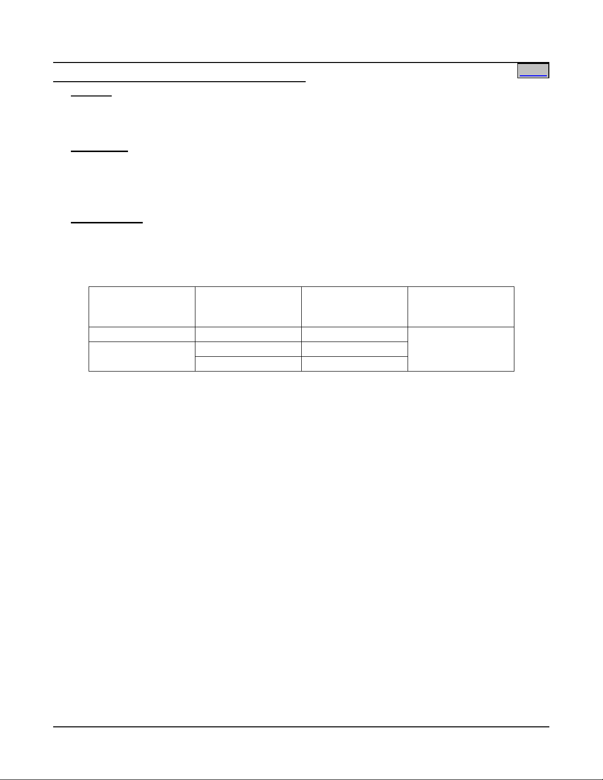
SAG582140001 System Application Guide
°
30°C
140
(5) 750 kcmil
140
(5) 750 kcmil
168
(6) 750 kcmil
Home
Issue AN, June 4, 2014 Spec. No. 582140001 (Model 801
NLDB, 801NLEB, 801NL-B)
Power Bay DC Output Cable Sizes and Lugs Selection
Features
♦ 3/8” clearance holes on 1" centers are provided for installation of customer provided DC output cables
terminated in two-hole lugs. These are accessed from the rear of each Power Bay.
♦ For lug mounting hole size and spacing dimensions, refer to the illustration provided in this section.
Restrictions
All lugs for customer connections must be ordered separately.
Customer needs to supply lug mounting hardware.
Maximum size of wire to be connected to a single lug position is 750 kcmil (2 per lug position).
Maximum lug width, 1.937 inches.
Ordering Notes
1) DC output cable size varies depending on power requirements, therefore no specific information is
provided for cable size. Refer to Table 11 for recommended cable sizes and lugs at rated maximum bay
output (2400 amperes). When making connections, observe correct polarity.
2) For other available lugs and hardware, refer to drawings 031110100 through 031110300.
Ambient Operating
Temperature
(1)
Loop
Length
(Ft)
(2)
Recm 90
Wire Size
C
(1, 2)
40°C
1
Cable sizes are based on recommendations of the American National Standards Institute
Recommended
Crimp Lug
245392000
(ANSI) approved National Fire Protection Association's (NFPA) National Electrical Code
(NEC). Table 310-16 for copper wire rated at 90
ambients of 30
°C and 40°C was used. For other operating ambient temperatures, refer to the
°C conductor temperature operating in
NEC. For operation in countries where the NEC is not recognized, follow applicable codes.
2
Recommended cable sizes are sufficient to restrict voltage drop to 1.0 volt or less at rated full
output current of the bay for the loop lengths shown. Loop length is the sum of the lengths of
the positive and negative leads.
3
Two-hole lug, 3/8" bolt clearance hole, 1" centers. Refer to drawing 031110100 for lug
crimping information.
Table 11
Recommended Power Bay DC Output Cable Size and Lug Selection
(3)
Page 44 of 115
This document is property of Emerson Network Power, Energy Systems, North America, Inc. and contains confidential and proprietary information owned by Emerson Network Power, Energy
Systems, North America, Inc. Any copying, use, or disclosure of it without the written permission of Emerson Network Power, Energy Systems, North America, Inc. is strictly prohibited.
Page 45
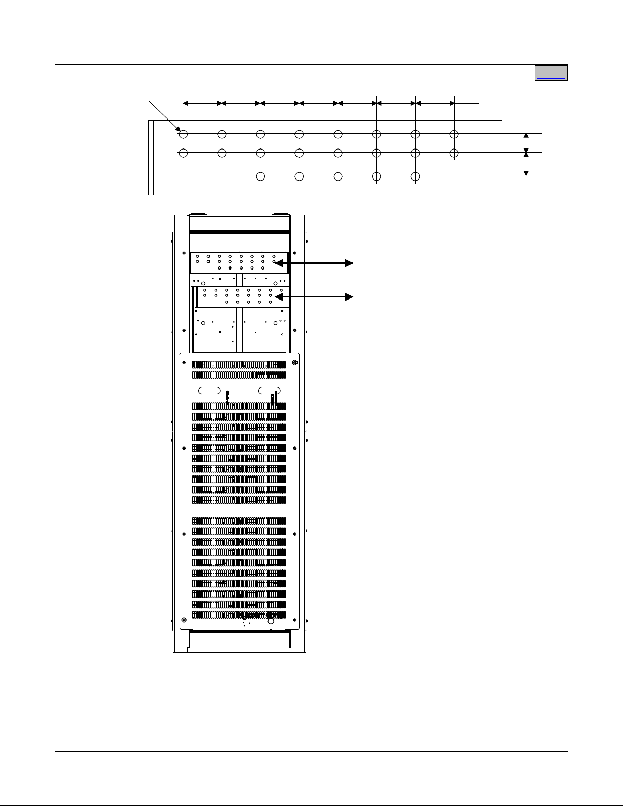
System Application Guide SAG582140001
Rear View
Power Bay
DC Output
Positive Busbar (+)
(Ground Return Bus)
DC Output
Negative Busbar (-)
(Supply -48V Bus)
Rear Cover Panel
Removed in Illustration
3/8" Clearance
Hole (21)
2.00"
1.00"
1.25"
Home
Spec. No. 582140001 (Model 801
NLDB, 801NLEB, 801NL-B) Issue AN, June 4, 2014
Page 45 of 115
This document is property of Emerson Network Power, Energy Systems, North America, Inc. and contains confidential and proprietary information owned by Emerson Network Power, Energy
Systems, North America, Inc. Any copying, use, or disclosure of it without the written permission of Emerson Network Power, Energy Systems, North America, Inc. is strictly prohibited.
Page 46

SAG582140001 System Application Guide
°
30°C
112
(10) 750 kcmil
112
(10) 750 kcmil
157
(14) 750 kcmil
Home
Issue AN, June 4, 2014 Spec. No. 582140001 (Model 801
NLDB, 801NLEB, 801NL-B)
Distribution Bay DC Input Cable Sizes and Lugs Selection
Features
♦ 3/8” clearance holes on 1" centers are provided for installation of customer provided DC input cables
terminated in two-hole lugs. These are accessed from the rear of each Distribution Bay.
♦ For lug mounting hole size and spacing dimensions, refer to the illustration provided in this section.
Restrictions
All lugs for customer connections must be ordered separately.
Customer needs to supply lug mounting hardware.
Maximum size of wire to be connected to a single lug position is 750 kcmil (2 per lug position).
Maximum lug width, 2.000 inches.
Ordering Notes
1) DC input cable size varies depending on power requirements, therefore no specific information is
provided for cable size. Refer to Table 12 for recommended cable sizes and lugs at rated maximum bay
load (6000 amperes). When making connections, observe correct polarity.
2) For other available lugs and hardware, refer to drawings 031110100 through 031110300.
Ambient Operating
Temperature
(1)
Loop
Length
(Ft)
(2)
Recm 90
Wire Size
C
(1, 2)
40°C
1
Wire sizes are based on recommendations of the American National Standards Institute
Recommended
Crimp Lug
245392000
(ANSI) approved National Fire Protection Association's (NFPA) National Electrical Code
(NEC). Table 310-16 for copper wire rated at 90
ambients of 30
°C and 40°C was used. For other operating ambient temperatures, refer to the
°C conductor temperature operating in
NEC. For operation in countries where the NEC is not recognized, follow applicable codes.
2
Recommended wire sizes are sufficient to restrict voltage drop to 1.0 volt or less at rated full
load output current of the bay for the loop lengths shown. Loop length is the sum of the
lengths of the positive and negative leads.
3
Two-hole lug, 3/8" bolt clearance hole, 1" centers. Refer to drawing 031110100 for lug
crimping information.
Table 12
Recommended Distribution Bay DC Input Cable Size and Lug Selection
(3)
Page 46 of 115
This document is property of Emerson Network Power, Energy Systems, North America, Inc. and contains confidential and proprietary information owned by Emerson Network Power, Energy
Systems, North America, Inc. Any copying, use, or disclosure of it without the written permission of Emerson Network Power, Energy Systems, North America, Inc. is strictly prohibited.
Page 47
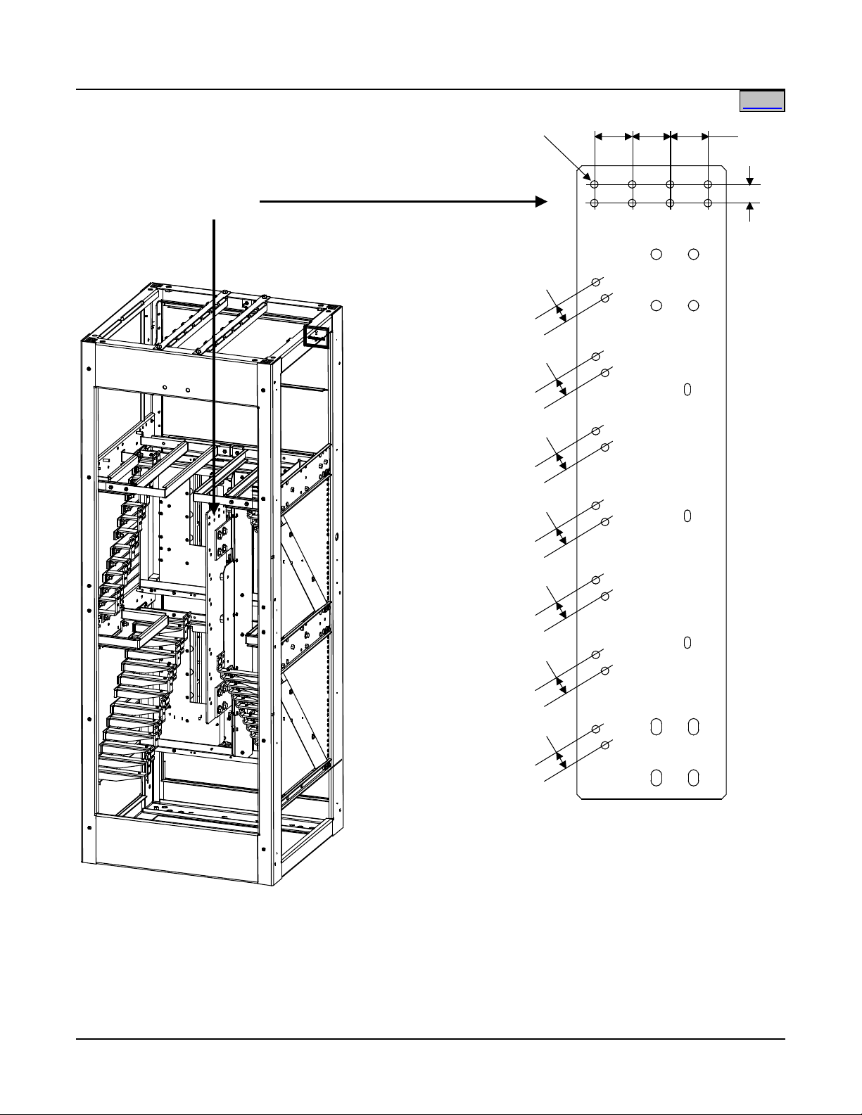
System Application Guide SAG582140001
3/8" Clearance Hole (22)
2.031"
1.00"
Rear View
Distribution Bay
1.00"
1.00"
1.00"
1.00"
1.00"
1.00"
1.00"
DC Input
(Supply -48V)
Home
Spec. No. 582140001 (Model 801
NLDB, 801NLEB, 801NL-B) Issue AN, June 4, 2014
This document is property of Emerson Network Power, Energy Systems, North America, Inc. and contains confidential and proprietary information owned by Emerson Network Power, Energy
Page 47 of 115
Systems, North America, Inc. Any copying, use, or disclosure of it without the written permission of Emerson Network Power, Energy Systems, North America, Inc. is strictly prohibited.
Page 48

SAG582140001 System Application Guide
Top View
Power Bay
1/4" clearance holes
on 5/8" centers are
provided for installation
of customer provided
two-hole lug.
1/4" clearance holes
on 5/8" centers are
provided for installation
of customer provided
two-hole lug.
Home
Issue AN, June 4, 2014 Spec. No. 582140001 (Model 801
Power Bay Frame Grounding Wire Sizes and Lugs Selection
Features
♦ 1/4” clearance holes on 5/8" centers are provided for installation of customer provided two-hole lugs, as
shown in the following illustration.
Restrictions
All lugs for customer connections must be ordered separately.
Customer needs to supply lug mounting bolts and hardware.
The recommended frame grounding wire size is 6 AWG.
Recommended lug P/N 245346700.
NLDB, 801NLEB, 801NL-B)
This document is property of Emerson Network Power, Energy Systems, North America, Inc. and contains confidential and proprietary information owned by Emerson Network Power, Energy
Systems, North America, Inc. Any copying, use, or disclosure of it without the written permission of Emerson Network Power, Energy Systems, North America, Inc. is strictly prohibited.
Page 48 of 115
Page 49

System Application Guide SAG582140001
Top View
Distribution Bay
1/4" clearance holes
on 5/8" centers are
provided for installation
of customer provided
two-hole lug.
1/4" clearance holes
on 5/8" centers are
provided for installation
of customer provided
two-hole lug.
Home
Spec. No. 582140001 (Model 801
NLDB, 801NLEB, 801NL-B) Issue AN, June 4, 2014
Distribution Bay Frame Grounding Wire Sizes and Lugs Selection
Features
♦ 1/4” clearance holes on 5/8" centers are provided for installation of customer provided two-hole lugs, as
shown in the following illustration.
Restrictions
All lugs for customer connections must be ordered separately.
Customer needs to supply lug mounting bolts and hardware.
The recommended frame grounding wire size is 6 AWG.
Recommended lug P/N 245346700.
This document is property of Emerson Network Power, Energy Systems, North America, Inc. and contains confidential and proprietary information owned by Emerson Network Power, Energy
Systems, North America, Inc. Any copying, use, or disclosure of it without the written permission of Emerson Network Power, Energy Systems, North America, Inc. is strictly prohibited.
Page 49 of 115
Page 50

SAG582140001 System Application Guide
Home
Issue AN, June 4, 2014 Spec. No. 582140001 (Model 801
NLDB, 801NLEB, 801NL-B)
AC Input (12 or 24 AC Input Feeds) Wire and Conduit Sizes, Branch Circuit Protection, and Lugs Selection Lists 5 and 13
Features
♦ 10-32 studs on 5/8” centers are provided for installation of customer provided two-hole AC Input lugs.
♦ 1/4-20 studs are provided for installation of customer provided two-hole AC equipment grounding lugs.
♦ For AC input wiring, refer to the illustration provided in this section.
Restrictions
Twelve (12) or twenty-four (24) AC input feeds are required in Lists 5 and 13 only.
24 Feeds, 208VAC, List B w/ List 5 or 13: Three feeds per conduit and one ground per conduit.
Customer must provide a high inrush circuit breaker overcurrent protection device in each AC input feed
as shown in Table 13.
24 Feeds, 380/480VAC, List A w/ List 5 or 13: Three feeds per conduit and one ground per conduit.
Customer must provide a high inrush circuit breaker overcurrent protection device in each AC input feed
as shown in Table 13.
12 Feeds, 208VAC, List B w/ List 5 or 13: Two feeds per conduit and one ground per conduit. Customer
must provide a high inrush circuit breaker overcurrent protection device in each AC input feed as shown
in Table 14.
12 Feeds, 380/480VAC, List A w/ List 5 or 13: Two feeds per conduit and one ground per conduit.
Customer must provide a high inrush circuit breaker overcurrent protection device in each AC input feed
as shown in Table 14.
All lugs for equipment grounding connections must be ordered separately. Customer needs to supply lug
mounting hardware.
Ordering Notes
1) Refer to Tables 13 (24 Feeds) and 14 (12 Feeds) for recommended AC input wire and conduit sizes,
branch circuit protection, and equipment grounding lugs.
Page 50 of 115
This document is property of Emerson Network Power, Energy Systems, North America, Inc. and contains confidential and proprietary information owned by Emerson Network Power, Energy
Systems, North America, Inc. Any copying, use, or disclosure of it without the written permission of Emerson Network Power, Energy Systems, North America, Inc. is strictly prohibited.
Page 51
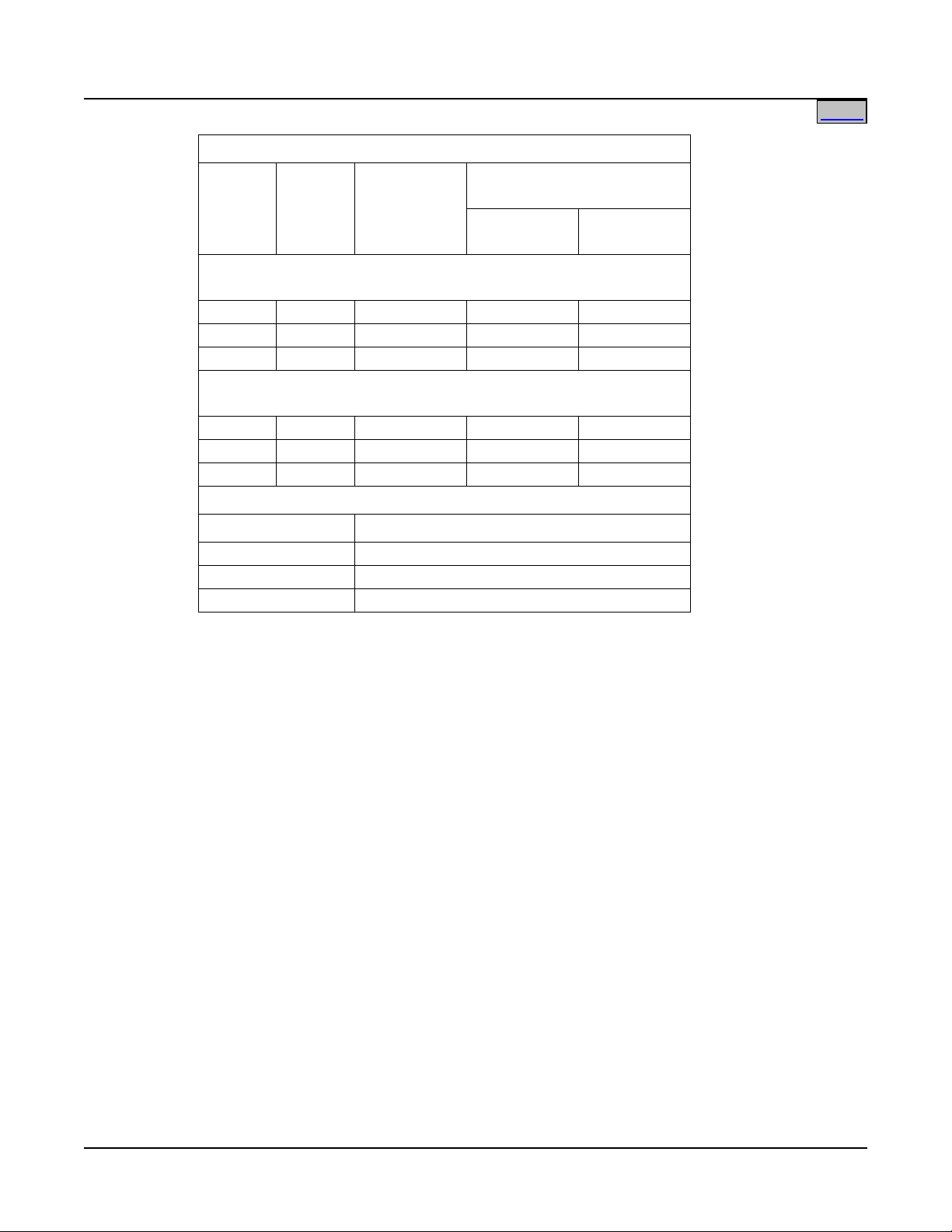
System Application Guide SAG582140001
208V
18A
25A
10
3/4
Home
Spec. No. 582140001 (Model 801
NLDB, 801NLEB, 801NL-B) Issue AN, June 4, 2014
24 Feeds
Input
Voltage
Input
Current
Overcurrent
Protection
40°C Ambient
Temperature
(1)
Wire
AWG
(2) (3)
(2)
Conduit
Size (in.)
THWN - 75°C Wire - Individual Feed
Three Rectifiers (9 Current and 1 Ground Wire) per Conduit
480V 7.8A 15A 14 1/2
380V 10A 15A 14 1/2
THHN - 90°C Wire - Individual Feed
Three Rectifiers (9 Current and 1 Ground Wire) per Conduit
480V 7.8A 15A 14 1/2
380V 10A 15A 14 1/2
208V 18A 25A 10 3/4
Recommended Equipment Grounding Wire Crimp Lugs
Wire AWG Crimp Lug P/N
(4)
14 245359650
10 245342300
8 245346600
1
The AC input branch circuit protective device should be of the
time-delay or high inrush type.
2
Wire sizes based on recommendations of the American National
Standards Institute (ANSI) approved National Fire Protection
Association's (NFPA) National Electrical Code (NEC). Table
310-16 for copper wire at 75°C and 90°C conductor temperature;
operating in an ambient of 40
°C was used. For other operating
ambient temperatures, refer to the National Electrical Code. For
operation in countries where the NEC is not recognized, follow
applicable codes.
3
Equipment grounding conductors must be provided with the AC
input conductors supplied to the Bay. Frame ground terminals
must be connected to earth ground, not power system neutral.
Equipment grounding conductor size based on recommendations
of the NEC Table 250-122 for copper wire. When aluminum or
copper clad aluminum grounding conductor is used, refer to Table
250-122 for increased conductor size. For operation in countries
where the NEC is not recognized, follow applicable codes.
4
Single-hole lug, 1/4" bolt clearance hole.
Table 13
Recommended AC Input Wire and Conduit Size, and Lug Selection
(24 AC Input Feeds, 1 per Rectifier Module)
Page 51 of 115
This document is property of Emerson Network Power, Energy Systems, North America, Inc. and contains confidential and proprietary information owned by Emerson Network Power, Energy
Systems, North America, Inc. Any copying, use, or disclosure of it without the written permission of Emerson Network Power, Energy Systems, North America, Inc. is strictly prohibited.
Page 52
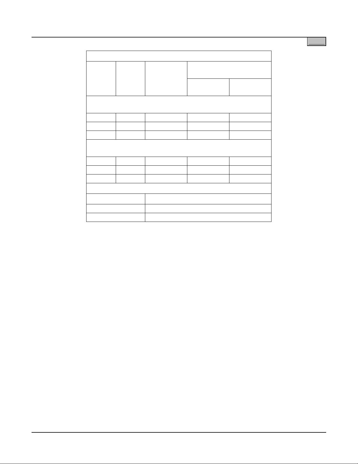
SAG582140001 System Application Guide
208V
35.8A
50A 6 1
Home
Issue AN, June 4, 2014 Spec. No. 582140001 (Model 801
NLDB, 801NLEB, 801NL-B)
12 Feeds
Input
Voltage
Input
Current
Overcurrent
Protection
40°C Ambient
Temperature
(1)
Wire
AWG
(2) (3)
(2)
Conduit
Size (in.)
THWN - 75°C Wire - Individual Feed
Four Rectifiers (6 Current and 1 Ground Wire) per Conduit
480V 15.6A 20A 12 1/2
380V 20A 25A 10 3/4
THHN - 90°C Wire - Individual Feed
Four Rectifiers (6 Current and 1 Ground Wire) per Conduit
480V 15.6A 20A 12 1/2
380V 20A 25A 10 3/4
208V 35.8A 50A 6 1
Recommended Equipment Grounding Wire Crimp Lugs
Wire AWG Crimp Lug P/N
(4)
8 245346600
6 245346500
1
The AC input branch circuit protective device should be of the
time-delay or high inrush type.
2
Wire sizes based on recommendations of the American National
Standards Institute (ANSI) approved National Fire Protection
Association's (NFPA) National Electrical Code (NEC). Table
310-16 for copper wire at 75°C and 90°C conductor temperature;
operating in an ambient of 40
°C was used. For other operating
ambient temperatures, refer to the National Electrical Code. For
operation in countries where the NEC is not recognized, follow
applicable codes.
3
Equipment grounding conductors must be provided with the AC
input conductors supplied to the Bay. Frame ground terminals
must be connected to earth ground, not power system neutral.
Equipment grounding conductor size based on recommendations
of the NEC Table 250-122 for copper wire. When aluminum or
copper clad aluminum grounding conductor is used, refer to Table
250-122 for increased conductor size. For operation in countries
where the NEC is not recognized, follow applicable codes.
4
Single-hole lug, 1/4" bolt clearance hole.
Table 14
Recommended AC Input Wire and Conduit Size, and Lug Selection
(12 AC Input Feeds, 1 per 2 Rectifier Modules)
Page 52 of 115
This document is property of Emerson Network Power, Energy Systems, North America, Inc. and contains confidential and proprietary information owned by Emerson Network Power, Energy
Systems, North America, Inc. Any copying, use, or disclosure of it without the written permission of Emerson Network Power, Energy Systems, North America, Inc. is strictly prohibited.
Page 53

System Application Guide SAG582140001
Home
Spec. No. 582140001 (Model 801
NLDB, 801NLEB, 801NL-B) Issue AN, June 4, 2014
AC Input (6 AC Input Feeds) Wire and Conduit Sizes, Branch Circuit Protection, and Lugs Selection Lists 6 and 14
Features
♦ 10-32 studs on 5/8” centers are provided for installation of customer provided two-hole AC Input lugs.
♦ 1/4-20 studs are provided for installation of customer provided two-hole AC equipment grounding lugs.
♦ For AC input wiring, refer to the illustration provided in this section.
Restrictions
Six (6) AC input feeds are required in Lists 6 and 14 only.
6 Feeds, 480V, List A w/ List 6 or 14: One feed per conduit and one ground per conduit. Customer must
provide a 40-50A high inrush circuit breaker overcurrent protection device in each AC input feed.
All lugs for equipment grounding connections must be ordered separately. Customer needs to supply lug
mounting hardware.
Ordering Notes
1) Refer to Table 15 for recommended AC input wire and conduit sizes, branch circuit protection, and
equipment grounding lugs.
Page 53 of 115
This document is property of Emerson Network Power, Energy Systems, North America, Inc. and contains confidential and proprietary information owned by Emerson Network Power, Energy
Systems, North America, Inc. Any copying, use, or disclosure of it without the written permission of Emerson Network Power, Energy Systems, North America, Inc. is strictly prohibited.
Page 54

SAG582140001 System Application Guide
Home
Issue AN, June 4, 2014 Spec. No. 582140001 (Model 801
NLDB, 801NLEB, 801NL-B)
6 Feeds
Input
Voltage
Input
Current
Overcurrent
Protection
40°C Ambient
Temperature
(1)
Wire
AWG
(2) (3)
(2)
Conduit
Size (in.)
THWN - 75°C Wire - Individual Feed
Four Rectifiers (6 Current and 1 Ground Wire) per Conduit
480V 31A 40A 8 3/4
480V 31A 50A 6 3/4
THHN - 90°C Wire - Individual Feed
Four Rectifiers (6 Current and 1 Ground Wire) per Conduit
480V 31A 40A 8 3/4
480V 31A 50A 6 3/4
Recommended Equipment Grounding Wire Crimp Lugs
Wire AWG Crimp Lug P/N
(4)
8 245346600
6 245346500
1
The AC input branch circuit protective device should be of the
time-delay or high inrush type.
2
Wire sizes based on recommendations of the American National
Standards Institute (ANSI) approved National Fire Protection
Association's (NFPA) National Electrical Code (NEC). Table
310-16 for copper wire at 75°C and 90°C conductor temperature;
operating in an ambient of 40
°C was used. For other operating
ambient temperatures, refer to the National Electrical Code. For
operation in countries where the NEC is not recognized, follow
applicable codes.
3
Equipment grounding conductors must be provided with the AC
input conductors supplied to the Bay. Frame ground terminals
must be connected to earth ground, not power system neutral.
Equipment grounding conductor size based on recommendations
of the NEC Table 250-122 for copper wire. When aluminum or
copper clad aluminum grounding conductor is used, refer to Table
250-122 for increased conductor size. For operation in countries
where the NEC is not recognized, follow applicable codes.
4
Single-hole lug, 1/4" bolt clearance hole.
Table 15
Recommended AC Input Wire and Conduit Size, and Lug Selection
(6 AC Input Feeds, 1 per 4 Rectifier Modules)
Page 54 of 115
This document is property of Emerson Network Power, Energy Systems, North America, Inc. and contains confidential and proprietary information owned by Emerson Network Power, Energy
Systems, North America, Inc. Any copying, use, or disclosure of it without the written permission of Emerson Network Power, Energy Systems, North America, Inc. is strictly prohibited.
Page 55

System Application Guide SAG582140001
No
te: Rec
ti
fi
e
r n
um
b
eri
ng is
for
wi
rin
g ide
nti
fic
ati
on on
ly.
T
he M
CA identifi
es
r
ec
t
if
ie
r
s
diffe
re
n
tl
y.
Re
ctif
ier
#1 M
ounting Slot
R
ect
ifier #3 Moun
ti
ng
S
lo
t
Rectifie
r #
5 M
o
un
ting
Slo
t
Re
c
ti
fi
er
#7 M
oun
ting
Slot
Re
ctif
ier
#9 Mounting Slot
R
ectifier #11 Mounti
ng
S
lo
t
Rec
tifier #
13 Mou
nti
ng Slo
t
Recti
fie
r #1
5 Mounti
ng Slo
t
Re
ctifie
r #17 Mou
nti
ng Slot
Rectifie
r #19 M
ounting Slot
Rect
ifier #21 Mo
unti
ng Slo
t
Rectifier #
23 Mounting Slo
t
Re
c
ti
fi
e
r #
2 Mo
unt
ing
Slot
R
ecti
fie
r #4
Mou
nting Slot
Re
cti
fier #6 Mountin
g S
l
ot
Rectifier #8 M
o
un
ti
n
g Sl
ot
R
ec
ti
f
ie
r #
10 M
oun
tin
g Slot
R
ect
ifie
r #1
2 Mounting Slot
Rectif
ier #
14 Mo
unting
Slot
Rect
ifier #1
6 Mount
ing
Slot
Rectifier #
18 M
ounting
Slot
Re
ctifier
#20 Moun
ting
Slot
Rectifier #22
Mounti
ng Slot
Rec
tifier
#24 Mountin
g Slot
Front Vie
w
P
ower Bay
T
op
V
iew
P
owe
r Bay
S
i
x
(
6
)
1
.
1
25
"
op
en
i
ng
s f
o
r 3
/4
"
co
nduit.
Tw
o (
2
) c
on
d
ui
t
pl
at
e
s with
2
.
5"
, 1
.75", and 1.125" knock-outs
fo
r 2",
1.5
", a
n
d 3
/4
"
co
nd
u
it
.
Si
x
(6
)
1.
75
"
ope
nin
gs f
or 1
.5" c
ond
uit
(un
der
pla
te)
.
See Detail A
(
1
2
F
e
e
ds
)
S
e
e
D
et
a
il
B
(24 Feeds)
S
ee
De
t
ai
l C
(6 F
ee
ds
)
Fro
n
t c
ov
e
r p
an
el
o
m
it
te
d
Home
Spec. No. 582140001 (Model 801
NLDB, 801NLEB, 801NL-B) Issue AN, June 4, 2014
This document is property of Emerson Network Power, Energy Systems, North America, Inc. and contains confidential and proprietary information owned by Emerson Network Power, Energy
Systems, North America, Inc. Any copying, use, or disclosure of it without the written permission of Emerson Network Power, Energy Systems, North America, Inc. is strictly prohibited.
Page 55 of 115
Page 56

SAG582140001 System Application Guide
AC Input
(10-32 Studs
on 5/8” Centers)
Ensure jumper busbars are installed.
Refer to the Installation Instructions (Section6016).
Rectifier #3 & #4
Mounting Slots
Phase A
Phase B
Phase C
Rectifier #7 & #8
Mounting Slots
Phase A
Phase B
Phase C
Rectifier #11 & #12
Mounting Slots
Phase A
Phase B
Phase C
Rectifier #15 & #16
Mounting Slots
Phase A
Phase B
Phase C
Rectifier #19 & #20
Mounting Slots
Phase A
Phase B
Phase C
Rectifier #23 & #24
Mounting Slots
Phase A
Phase B
Phase C
Rectifier #1 & #2
Mounting Slots
Phase A
Phase B
Phase C
Rectifier #5 & #6
Mounting Slots
Phase A
Phase B
Phase C
Rectifier #9 & #10
Mounting Slots
Phas
e A
Phase B
Phase C
Rectifier #13 & #14
Mounting Slots
Phase A
Phase B
Phase C
Rectifier #17 & #18
Mounting Slots
Phase A
Phase B
Phase C
Rectifier #21 & #22
Mounting Slots
Phase A
Phase B
Phase C
Detail A
380/480VAC (List A) or 208VAC (List B)
3 Phase, 50/60Hz
(12 AC Input Feeds,
1 per 2 Rectifier Modules)
Equipment
Grounding
(1/4-20 Studs
on 1” Centers)
Home
Issue AN, June 4, 2014 Spec. No. 582140001 (Model 801
NLDB, 801NLEB, 801NL-B)
This document is property of Emerson Network Power, Energy Systems, North America, Inc. and contains confidential and proprietary information owned by Emerson Network Power, Energy
Systems, North America, Inc. Any copying, use, or disclosure of it without the written permission of Emerson Network Power, Energy Systems, North America, Inc. is strictly prohibited.
Page 56 of 115
Page 57
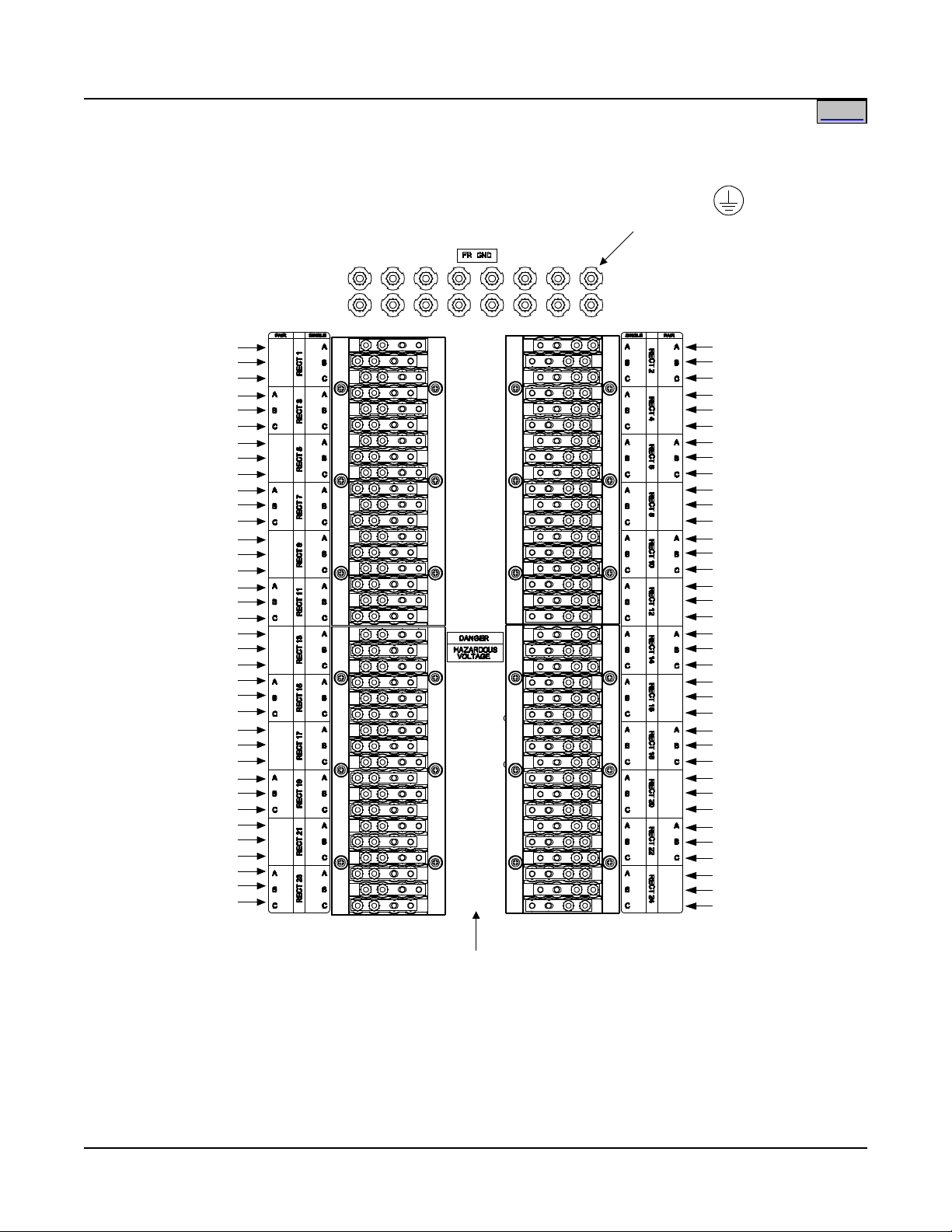
System Application Guide SAG582140001
Ph a
se A
Ph
a s e
C
Ph
a s e
B
Ph a se A
P
ha
se
C
P
ha
se B
Ph a s
e A
Ph a
se C
Ph a se
B
P
h
a
s
e
A
P h a se C
P
h
a
s
e
B
P h
ase
A
P
has
e C
P
h
as
e
B
P h a se A
P h
ase C
P h
ase B
E q u ip m e
n
t
G
r
o
u
nd
in
g
(1
/
4-20 S tu d s
o
n
1
"
C
e
n
t
e
r
s
)
P
ha
se
A
P
ha
s
e C
P h a se B
P
h a s
e A
Ph a
se C
Ph
a
se B
Ph
a s e
A
Ph
a
se C
Ph a se
B
P
h
as
e A
P h a
se
C
P h a s
e B
Ph a s
e A
P
h a s e
C
P
h
as
e B
P
h a
se
A
Ph
as
e C
Ph a se B
AC Input
(
10-32 Studs
on 5/8” Centers)
Ensure
jumper bu
sbar
s are NOT ins
tal
led.
Re
fer t
o the Installat
ion
Instru
ctions (Sec
tio
n 6016
).
Detail B
3
8
0/
48
0
VAC (List A) ro 208
VA
C
(
L
i
s
t
B
)
3 Phase, 50/60H
z
(24 AC Input Feeds
,
1 per Rectifier Modu
le
)
Rectifie
r
#3
Mounting S
l
ot
R
e
ct
i
f
i
e
r
#7
M
o
u
n
t
i
n
g
Sl
ot
Rec
tif
ier
#11
Mou
nti
ng S
lot
Rect
ifi
er #15
M
oun
tin
g Slot
Rec
tif
ier
#19
Mo
unti
ng Slot
R
ectifi
er #23
Mo
untin
g Slot
R
e
c
t
i
f
i
e
r
#
2
M
o
u
n
t
i
n
g
S
l
o
t
Rect
ifi
er #
6
M
oun
tin
g Slo
t
R
ect
ifi
er
#1
0
Mou
nti
ng
Sl
o
t
Re
cti
fie
r #1
4
Mo
unti
ng S
lot
Rec
tif
ier
#18
Mou
nti
ng Slot
R
ect
ifi
er #22
Mo
unt
ing Slot
P h a
se
A
P h a se C
P
h
a
s
e
B
P h a
se A
P
ha s e
C
P
ha s
e B
P h a
s
e A
P
ha s
e C
P h a
se B
P h
a s e
A
P
ha s
e C
P h a s
e B
P
ha s
e A
P
ha s
e C
P h
a
se
B
P h a
se A
P h
a s e C
P
ha s e B
Rectifier #1
Mounting Slot
Re
cti
fier
#5
Mou
nti
ng S
lot
Rec
tif
ier #
9
Mo
unt
ing
Slo
t
R
ec
tif
ier #
13
M
ou
nti
ng S
lot
R
ec
ti
f
ie
r #1
7
M
o
un
t
in
g Sl
ot
Re
ct
if
ier #
21
M
ou
nt
ing
Slot
P
h
a
s
e
A
P h a se C
P
h
a
s
e
B
P h
ase
A
P h
ase
C
P h a se
B
P h a
se A
P h a
se C
P h
ase
B
Ph
ase
A
Ph
a
se
C
Ph a
se
B
P
has e
A
P h
ase C
P h
ase B
Ph
ase A
P
h a s e
C
Ph
a
se
B
Re
ct
ifie
r #8
Mo
unt
ing
Slot
R
e
ct
if
i
er #
12
M
ou
nt
i
ng S
lot
Rec
tif
ier
#16
Mo
unti
ng S
lot
Rectifier #20
M
ounting Slot
R
ectifie
r #24
Moun
ting Slo
t
R
e
ct
i
fi
er
#
4
Mo
un
t
in
g
Sl
ot
Home
Spec. No. 582140001 (Model 801
NLDB, 801NLEB, 801NL-B) Issue AN, June 4, 2014
This document is property of Emerson Network Power, Energy Systems, North America, Inc. and contains confidential and proprietary information owned by Emerson Network Power, Energy
Systems, North America, Inc. Any copying, use, or disclosure of it without the written permission of Emerson Network Power, Energy Systems, North America, Inc. is strictly prohibited.
Page 57 of 115
Page 58

SAG582140001 System Application Guide
Detail C
408VAC (List A)
(6 AC Input Feeds,
1 per 4 Rectifier Modules)
Equipment
Grounding
(1/4-20 Studs
on 1" Centers)
AC Input
(10-32 Studs
on 5/8" Centers)
Ensure jumper busbars and jumper wires are installed.
(Jumpers wires not sh
own.)
Refer to the Installation Instructions (Section 6016).
Phase A
Phase C
Phase B
Phase A
Phase C
Ph
ase B
Phase A
Phase C
Phase B
Phase A
Phase C
Phase B
Phase A
Phase C
Phase B
Phase A
Phase C
Phase B
Rectifier #1,
#2, #3, & #4
Mounting Slots
Rectifier #9,
#10, #11, & #1
2
Mounting Slots
Rectifier #17,
#18, #19, & #20
Mounting Slots
Rectifier #5,
#
6,
#
7, & #8
Mounting Slots
Re
ctifier #13,
#14, #15, & #16
Mounting Slots
Rectifier #21
,
#22, #23,
& #24
Mounting Slots
Home
Issue AN, June 4, 2014 Spec. No. 582140001 (Model 801
NLDB, 801NLEB, 801NL-B)
This document is property of Emerson Network Power, Energy Systems, North America, Inc. and contains confidential and proprietary information owned by Emerson Network Power, Energy
Systems, North America, Inc. Any copying, use, or disclosure of it without the written permission of Emerson Network Power, Energy Systems, North America, Inc. is strictly prohibited.
Page 58 of 115
Page 59

System Application Guide SAG582140001
Home
Spec. No. 582140001 (Model 801
NLDB, 801NLEB, 801NL-B) Issue AN, June 4, 2014
AC Input (2 AC Input Feeds) Wire and Conduit Sizes, Branch Circuit Protection, and Lugs Selection Lists 4 and 12
Features
♦ 3/8-16 studs on 1” centers are provided for installation of customer provided two-hole AC Input lugs.
♦ 1/4-20 studs are provided for installation of customer provided two-hole AC equipment grounding lugs.
♦ For AC input wiring, refer to the illustration provided in this section.
Restrictions
Two (2) AC input feeds are required in Lists 4 and 12 only. One feed per conduit and one ground per conduit.
2 Feeds, 208VAC, List B w/ List 4 or 12: Customer must provide a 300A high inrush circuit breaker
overcurrent protection device in each AC input feed.
2 Feeds, 380VAC, List A w/ List 4 or 12: Customer must provide a 150A high inrush circuit breaker
overcurrent protection device in each AC input feed.
2 Feeds, 480VAC, List A w/ List 4 or 12: Customer must provide a 125A high inrush circuit breaker
overcurrent protection device in each AC input feed.
All lugs for customer connections must be ordered separately.
Customer needs to supply lug mounting hardware.
Ordering Notes
1) Refer to Table 16 for recommended AC input wire and conduit sizes, branch circuit protection, and lugs.
Page 59 of 115
This document is property of Emerson Network Power, Energy Systems, North America, Inc. and contains confidential and proprietary information owned by Emerson Network Power, Energy
Systems, North America, Inc. Any copying, use, or disclosure of it without the written permission of Emerson Network Power, Energy Systems, North America, Inc. is strictly prohibited.
Page 60
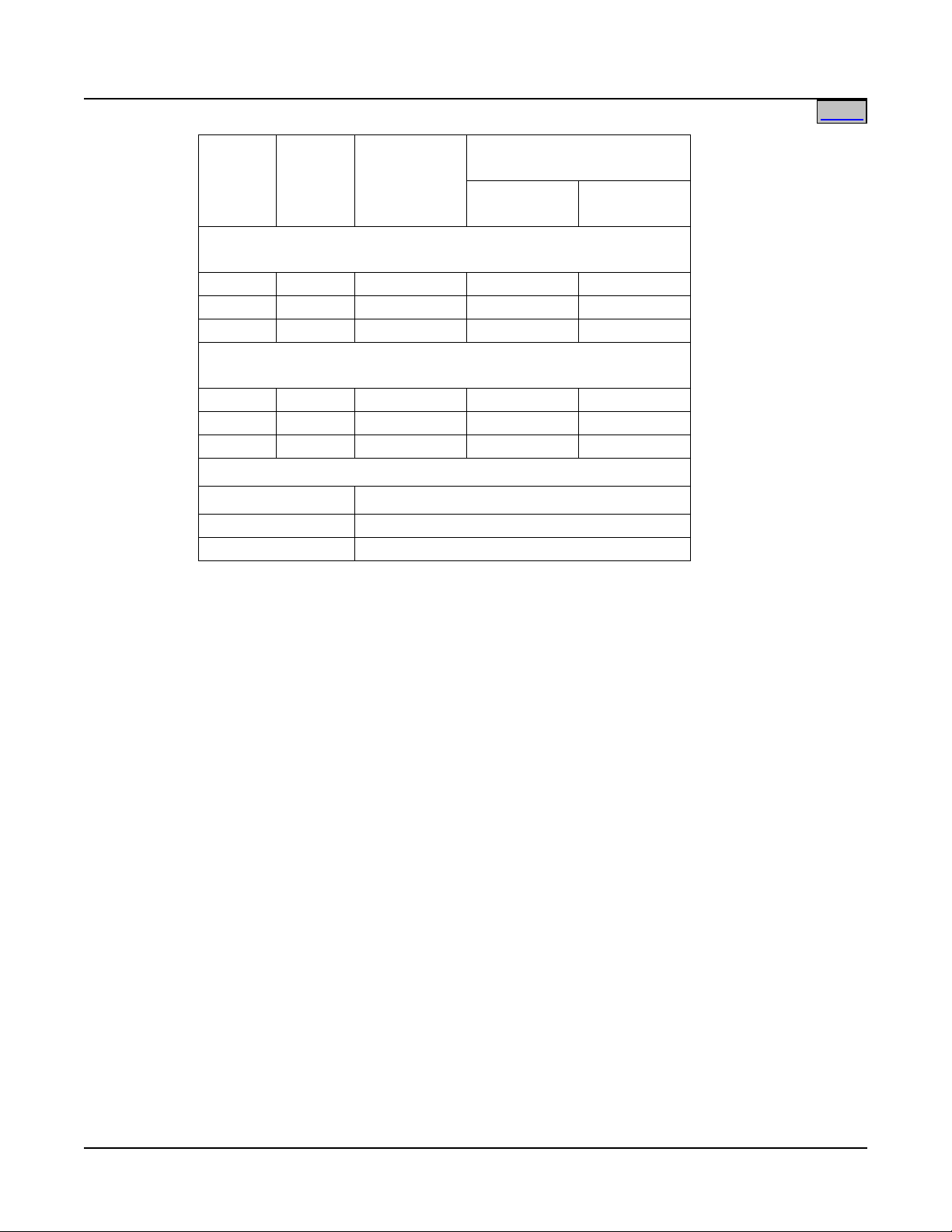
SAG582140001 System Application Guide
Home
Issue AN, June 4, 2014 Spec. No. 582140001 (Model 801
NLDB, 801NLEB, 801NL-B)
Input
Voltage
Input
Current
Overcurrent
Protection
40°C Ambient
Temperature
(1)
Wire
AWG
(2) (3)
(2)
Conduit
Size (in.)
THWN - 75°C Wire - Dual Feed
Twelve Rectifiers (3 Current and 1 Ground Wire) per Conduit
480V 91A 125A 1/0 1-1/2
380V 115A 150A 1/0 1-1/2
208V 212A 300A 300 kcmil 2-1/2
THHN - 90°C Wire - Dual Feed
Twelve Rectifiers (3 Current and 1 Ground Wire) per Conduit
480V 91A 125A 2 1-1/2
380V 115A 150A 1/0 1-1/2
208V 212A 300A 300 kcmil 2-1/2
Recommended Crimp Lugs
Wire AWG Crimp Lug P/N
(4)
1/0 245347100
350 kcmil 245347700
1
The AC input branch circuit protective device should be of the
time-delay or high inrush type.
2
Wire sizes based on recommendations of the American National
Standards Institute (ANSI) approved National Fire Protection
Association's (NFPA) National Electrical Code (NEC). Table
310-16 for copper wire at 75°C and 90°C conductor temperature;
operating in an ambient of 40
°C, was used. For other operating
ambient temperatures, refer to the National Electrical Code. For
operation in countries where the NEC is not recognized, follow
applicable codes.
3
Equipment grounding conductors must be provided with the AC
input conductors supplied to the Bay. Frame ground terminals
must be connected to earth ground, not power system neutral.
Equipment grounding conductor size based on recommendations
of the NEC Table 250-122 for copper wire. When aluminum or
copper clad aluminum grounding conductor is used, refer to Table
250-122 for increased conductor size. For operation in countries
where the NEC is not recognized, follow applicable codes.
4
Two-hole lug, 3/8” bolt clearance hole, 1" centers. Refer to
drawing 031110100 for lug crimping information.
Table 16
Recommended AC Input Wire and Conduit Size, and Lug Selection
(2 AC Input Feeds, 1 per 12 Rectifier Modules)
Page 60 of 115
This document is property of Emerson Network Power, Energy Systems, North America, Inc. and contains confidential and proprietary information owned by Emerson Network Power, Energy
Systems, North America, Inc. Any copying, use, or disclosure of it without the written permission of Emerson Network Power, Energy Systems, North America, Inc. is strictly prohibited.
Page 61

System Application Guide SAG582140001
CB1
CB2
CB3
CB4
CB5
CB6
CB7
CB8
CB9
CB10
CB11
CB12
Odd Numbered
Rectifier Mounting
Slots
Even Numbered
Rectifier Mounting
Slots
380/480VAC (List A) or 208VAC (List B)
3 Phase, 50/60Hz
(2 AC Input Feeds,
1 per 12 Rectifier Modules)
Rectifier #1 Mounting Slot
Rectifier #3 Mounting Slot
Rectifier #5 Mounting Slot
Rectifier #7 Mounting Slot
Rectifier #9 Mounting Slot
Rectifier #11 Mounting Slot
Rectifier #13 Mounting Slot
Rectifier #15 Mounting Slot
Rectifier #17 Mounting Slot
Rectifier #19 Mounting Slot
Rectifier #21 Mounting Slot
Rectifier #23 Mounting Slot
Rectifier #2 Mounting Slot
Rectifier #4 Mounting Slot
Rectifier #6 Mounting Slot
Rectifier #8 Mounting Slot
Rectifier #10 Mounting Slot
Rectifier #12 Mounting Slot
Rectifier #14 Mounting Slot
Rectifier #16 Mounting Slot
Rectifier #18 Mounting Slot
Rectifier #20 Mounting Slot
Rectifier #22 Mounting Slot
Rectifier #24 Mounting Slot
Front cover panel
removed in illustration
Front View
Power Bay
C B A A B C
Top View
Power Bay
Note: Rectifier numbering is for
wiring identification only.
The MCA identifies rectifiers
differently.
Equipment
Grounding
(1/4-20 Studs
on 1" Centers)
AC Input
(3/8-16 Studs
on 1" Centers)
Six (6) 1.125" openings for 3/4" conduit.
Two (2) conduit plates with
2.5", 1.75", and 1.125" knock-outs
for 2", 1.5", and 3/4" conduit.
Six (6) 1.75" openings for 1.5" conduit
(under plate).
Home
Spec. No. 582140001 (Model 801
NLDB, 801NLEB, 801NL-B) Issue AN, June 4, 2014
This document is property of Emerson Network Power, Energy Systems, North America, Inc. and contains confidential and proprietary information owned by Emerson Network Power, Energy
Systems, North America, Inc. Any copying, use, or disclosure of it without the written permission of Emerson Network Power, Energy Systems, North America, Inc. is strictly prohibited.
Page 61 of 115
Page 62

SAG582140001 System Application Guide
AWG
18-20 AWG for Loop Lengths Over 200 ft.
MCA Circuit Card P/N 509478
(Primary Bay)
1
10
1
9
10
18
TB1
MCA Customer Alarm
Relay Circuit Card P/N 514348
(Primary and/or Secondary Bays)
MCA Circuit Card
(Primary Power Bay only)
MCA Customer Alarm Relay Circuit Cards
and/or LMS Input/Output (I/O) Circuit Cards.
TB1
Home
Issue AN, June 4, 2014 Spec. No. 582140001 (Model 801
NLDB, 801NLEB, 801NL-B)
External Alarm, Reference, and Control Wire Sizes - Power Bays
Features
♦ External Alarm, Reference, and Control connections are made to TB1 on the MCA circuit card and TB1
on the MCA Customer Alarm Relay Circuit Cards.
Terminals
Capacity Type
28 to 16
Screw Clamp
22 AWG for Loop Lengths Up to 200 ft.
Recm
Wire Size
Table 17
Recommended Alarm, Reference, and Control Wire Size
(TB1 on MCA Circuit Card)
(TB1 on MCA Customer Alarm Relay Circuit Card)
This document is property of Emerson Network Power, Energy Systems, North America, Inc. and contains confidential and proprietary information owned by Emerson Network Power, Energy
Systems, North America, Inc. Any copying, use, or disclosure of it without the written permission of Emerson Network Power, Energy Systems, North America, Inc. is strictly prohibited.
Page 62 of 115
Page 63

System Application Guide SAG582140001
SLOPE
Adjustable from 0.0 V / °C
to 0.2 V / °C
MIN W/T
Adjustable from
Float to 44V
MAX W/T
Adjustable from
Float to 58.5V max.*
+25°C
(+77°F)
FLOAT
Determines Float Mode
Output Voltage at 25°C.
Adjustable from 47.0V
to 58.0V max.*
Temperature
IncreasingDecreasing
Voltage
Decreasing
Increasing
* Maximum setting is automatically
limited to 1.0 volt less than HVSD setting.
Home
Spec. No. 582140001 (Model 801
NLDB, 801NLEB, 801NL-B) Issue AN, June 4, 2014
Optional Battery Charge Temperature Compensation Probe for Digital Compensation
Features
♦ This system can be used with a Battery Charge Temperature Compensation Probe. This probe must be
mounted near the battery to sense battery ambient temperature. The probe connects to and allows the
MCA to automatically increase or decrease the output voltage of the system to maintain battery float
current as battery ambient temperature decreases or increases, respectively. Battery life can be
extended when an optimum charge voltage to the battery with respect to temperature is maintained.
♦ Refer to the "Specifications" section of this document for further information.
♦ Temperature Curve: The following figure details a user defined, via the MCA, Temperature
Compensation Probe Curve.
Ordering Notes
1) Order one Battery Charge Temperature Compensation Probe per power system. Part No. 107021 has a
25-foot long cord. Part No. 106824 has a 100 foot-long cord.
Using Optional Battery Charge Digital Temperature Compensation Probe
Typical Float Charge Thermal Characteristics
Page 63 of 115
This document is property of Emerson Network Power, Energy Systems, North America, Inc. and contains confidential and proprietary information owned by Emerson Network Power, Energy
Systems, North America, Inc. Any copying, use, or disclosure of it without the written permission of Emerson Network Power, Energy Systems, North America, Inc. is strictly prohibited.
Page 64

SAG582140001 System Application Guide
Home
Issue AN, June 4, 2014 Spec. No. 582140001 (Model 801
NLDB, 801NLEB, 801NL-B)
Replacement/Additional MCA Network Cable
Features
♦ MCA bay-to-bay interconnect cable. Connects between bay expansion ports located on the bay's MCA
(Primary Power Bay) and Router (Secondary Power Bays and Distribution Bays) circuit cards.
♦ Cable identification color is yellow.
Restrictions
Maximum combined cable length must not exceed 125 feet.
Ordering Notes
1) For a replacement or additional cable, order the proper length cable from those listed below.
P/N 514642 (3 feet) (factory provided with List 9 and 10)
P/N 514643 (4 feet)
P/N 514644 (6 feet) (factory provided with List 16)
P/N 524726 (15 feet)
P/N 514645 (25 feet)
P/N 514646 (50 feet)
P/N 514647 (100 feet)
Replacement/Additional LMS Network Cable
Features
♦ LMS bay-to-bay interconnect cable. Connects between the bay's LMS Echelon expansion ports. Also
connects the LMS System to LMS Expansion Cabinets and Assemblies, if furnished.
♦ Cable identification color is blue.
Restrictions
Refer to SAG586505000 (LMS System Application Guide) for maximum LMS network cabling length.
Ordering Notes
1) For a replacement or additional cable, order the proper length cable from those listed below.
P/N 524409 (5 inches)
P/N 509070 (6 inches)
P/N 528520 (10 inches)
P/N 509071 (15 inches)
P/N 524410 (2 feet)
P/N 514639 (3 feet) (factory provided with List 63)
P/N 509900 (4 feet)
P/N 514640 (25 feet)
P/N 514641(150 feet)
Page 64 of 115
This document is property of Emerson Network Power, Energy Systems, North America, Inc. and contains confidential and proprietary information owned by Emerson Network Power, Energy
Systems, North America, Inc. Any copying, use, or disclosure of it without the written permission of Emerson Network Power, Energy Systems, North America, Inc. is strictly prohibited.
Page 65

System Application Guide SAG582140001
Rectifier Module, 208VAC Input
Order via List 21
Rectifier Module, 380/480VAC Input
Order via List 22
Rectifier Module Fan
32010109
MCA Circuit Card
(Distribution Bays)
LMS Primary CPU Circuit Card
(Secondary Power Bay)
MCA Customer Alarm
Home
Spec. No. 582140001 (Model 801
NLDB, 801NLEB, 801NL-B) Issue AN, June 4, 2014
Replacement Modules and Circuit Cards
Ordering Notes
1) Refer to the following table.
Item Part Number
(Primary Power Bay)
509478
Router Circuit Card
(Secondary Power Bay
509509
and Distribution Bays)
Distribution Monitoring Circuit Card
(Primary Power Bay)
LMS Expansion CPU Circuit Card
Relay Circuit Card
524982
Order via List 50
Order via List 63
Order via List 70
MCA I/O Circuit Card Order via List 71
This document is property of Emerson Network Power, Energy Systems, North America, Inc. and contains confidential and proprietary information owned by Emerson Network Power, Energy
Systems, North America, Inc. Any copying, use, or disclosure of it without the written permission of Emerson Network Power, Energy Systems, North America, Inc. is strictly prohibited.
Page 65 of 115
Page 66

SAG582140001 System Application Guide
Home
Issue AN, June 4, 2014 Spec. No. 582140001 (Model 801
NLDB, 801NLEB, 801NL-B)
SPECIFICATIONS
1. SYSTEM
1.1 DC Operating Voltage
1.1.1 Nominal: -48Vdc.
1.1.2 Range: -42Vdc to -60Vdc.
1.2 Environmental Ratings
Note: See also ‘Environmental Ratings’ in the Rectifier Module section.
1.2.1 Operating Ambient Temperature Range: 0°C to +40°C (+32°F to +104°F).
1.2.2 Storage Ambient Temperature Range: -40°C to +65°C (-40°F to +149°F).
1.2.3 Humidity: This system is capable of operating in an ambient relative humidity range of 0% to
95%, noncondensing.
1.2.4 Altitude: The maximum operating ambient temperature should be derated by 10°C at an
elevation of 10,000 feet above sea level. For elevations between 3,000 feet and 10,000 feet,
derate the maximum operating ambient temperature linearly.
1.2.5 Heat Dissipation: With Rectifier Module output adjusted to 54.48 volt DC at rated full load and
nominal input voltage.
No. of
Rectifier
Modules
Power Bay Output
Current (Amperes)
1R485800
Rectifier
(Typical)
1R485800L
Rectifier
1 100 1472 1739
24 2400 35328 41726
1.2.6 Ventilation Requirements: The Rectifier Modules are fan cooled and utilize front to back
forced ventilation. The Power Bays must be mounted so ventilating openings are not blocked
and temperature of the air entering the Rectifier Module shelf does not exceed the Operating
Ambient Temperature Range stated above.
1.2.7 Audible Noise: The audible noise does not exceed the following when measured at any point
two feet from any vertical surface of a Power Bay and five feet from the floor using a Sound
Level Meter conforming to ANSI S1.4.
No. of
BTU/Hr
Rectifier
Audible Noise
Modules
1 50 dBA
24 60 dBA
1.2.8 EMI/RFI Suppression: Rectifier Modules operating in a Power Bay conform to the
requirements of FCC rules Part 15, Subpart B, Class A for Radiated and Conducted emissions
limits.
1.2.9 Surge Protection: Compliance with EN61000-4-5 Installation Class 4, and capable of
withstanding surges per ANSI/IEEE C 62.41-1991 Category B across the input terminals.
Note: This level of protection is a widely used standard for telecommunications power
equipment. As with all such equipment, it is the end user's responsibility to provide an
adequately sized Surge Suppression Device at the commercial power service entrance of
the building that reduces all incoming surges to levels below the classes/categories
stated for the equipment.
1.2.10 ESD Protection: Complies with EN61000-4-2 Level 4 (8kV contact).
Page 66 of 115
This document is property of Emerson Network Power, Energy Systems, North America, Inc. and contains confidential and proprietary information owned by Emerson Network Power, Energy
Systems, North America, Inc. Any copying, use, or disclosure of it without the written permission of Emerson Network Power, Energy Systems, North America, Inc. is strictly prohibited.
Page 67

System Application Guide SAG582140001
Home
Spec. No. 582140001 (Model 801
NLDB, 801NLEB, 801NL-B) Issue AN, June 4, 2014
1.2.11 Electrical Fast Transient / Burst Immunity: Complies with EN61000-4-4 Level 4.
1.2.12 Mounting: This Power System is intended only for installation in a Restricted Access
Location on or above a non-combustible surface. Typical industry standards recommend
minimum aisle space clearance of 2'6" for the front of the relay rack and 2' for the rear of the
relay rack.
1.3 Compliance Information
1.3.1 Safety Compliance
(A) Model 801
NLEB and 801NLDB (Power Bay): This unit meets the requirements of UL 60950,
Standard for Information Technology Equipment, and is UL Listed as a power supply for use
in Telephone, Electronic Data Processing or Information Processing Equipment.
(B) Model 801
NL-B (Distribution Bay): This power board is UL Listed as a DC Power
Distribution Center for Communications Equipment.
1.3.2 NEBS Compliance
(A) Model 801
NLEB (Power Bay) and Model 801NL-B (Distribution Bay): Compliance verified
by a Nationally Recognized Testing Laboratory (NRTL) per GR-1089-CORE and
GR-63-CORE. Contact Emerson Network Power for NEBS compliance reports.
(B) Model 801
NLDB (Power Bay) (Lists 0B, 05, 13, 21, 50, 63, 64, 65, 66, 67, 70, 71):
Compliance verified by a Nationally Recognized Testing Laboratory (NRTL) per
GR-1089-CORE and GR-63-CORE. Contact Emerson Network Power for NEBS
compliance reports.
In order to remain compliant during a fan failure condition, the backup battery connection must
be utilized to provide sufficient power to the loads for up to eight (8) hours when the system is
operated at greater than 50% output power. If no backup battery connection is used, the system
must operate with a redundant module installed.
1.4 Local Controls and Indicators
1.4.1 "Bay Alarm" Indicator: Located at the top center of each bay.
Green = OK
Red = Bay Failure
Yellow (flashing) = Identified by the MCA
1.4.2 MCA Component Identification Indicator: Each MCA component (i.e. Rectifier Module, Bus
Monitoring Circuit Card, Bay Router Circuit Card, MCA Relay Circuit Card) contains an ID LED
Indicator. The ID indicator illuminates Green when the component is OK, Red when the
component has failed, and flashing yellow when the component is identified by the MCA.
1.4.3 "Distribution Bus" Indicators: Each distribution bus contains and indicator located on a
hinged door panel covering the bus's MCA Monitoring circuit card.
Green = OK
Red = Card Failure
Yellow (flashing) = Identified by the MCA
1.4.4 See also ‘Local Controls and Indicators’ in the Rectifier Module, MCA, and LMS sections.
2. DISTRIBUTION BAY
2.1 DC Ratings
2.1.1 Bay: 6000 amperes, maximum, per bay.
16,800 amperes, maximum, per system.
2.1.2 Bus: 1500 amperes, maximum.
Each bay has four (4) Distribution Buses.
Optional Distribution Panel: 500 amperes, maximum.
One optional Distribution Panel per Distribution Bay.
2.1.3 Fuse/Circuit Breaker Mounting Positions: Each Distribution Bus contains 12 fuse/circuit
breaker mounting positions which provides 48 fuse/circuit breaker mounting positions per bay.
Page 67 of 115
This document is property of Emerson Network Power, Energy Systems, North America, Inc. and contains confidential and proprietary information owned by Emerson Network Power, Energy
Systems, North America, Inc. Any copying, use, or disclosure of it without the written permission of Emerson Network Power, Energy Systems, North America, Inc. is strictly prohibited.
Page 68

SAG582140001 System Application Guide
Home
Issue AN, June 4, 2014 Spec. No. 582140001 (Model 801
NLDB, 801NLEB, 801NL-B)
Note that some fuse/circuit breaker combinations require more than one fuse/circuit
breaker mounting position. Refer to Distribution Devices under ACCESSORY
DESCRIPTIONS for details.
The optional Distribution Panel provides twenty-four (24) Bullet Nose Device positions. The
panel accepts a choice of TLS/TPS-type fuseholders or Bullet Nose-type circuit breakers. When
installed, bay can be loaded with up to (46) 218 Circuit Breakers or TPL Fuses, and (24) Bullet
Nose Circuit Breakers or TLS/TPS Fuses.
Note: The List C Circuit Breaker/Fuse Panel requires distribution position #12 in the Bus #1
Distribution Panel. Also, distribution position #36 in the Bus #3 Distribution Panel must
remain empty.
3. RECTIFIER MODULE (MODEL R48-5800, SPEC. NO. 1R485800)
3.1 DC Output Ratings
3.1.1 Voltage: Nominal -48 volts DC, Positive Ground.
(A) Without Battery Charge Temperature Compensation: Float voltage is adjustable from
47.00 to 58.00 volts DC. Test/equalize voltage is adjustable from 45.00 to 58.00 volts DC.
Adjustment is made via the MCA. Both float and test/equalize voltages are factory set at
52.00 volts, unless otherwise specified. The output voltage temperature coefficient (1/°C)
does not exceed 0.01% per degree centigrade from 0°C to +40°C.
(B) With Battery Charge Digital Temperature Compensation Probe: With an optional battery
charge digital temperature compensation probe installed, the MCA automatically increases
or decreases the output voltage as battery ambient temperature decreases or increases,
respectively. Float voltage is factory set at approximately 54.48 volts at 25°C battery
ambient. The float and test/equalize voltage range is the same as without battery charge
temperature compensation. Using battery and equipment manufacturers’ recommendations,
the user selects the following temperature compensation curve parameters via the MCA.
Refer to "Typical Float Charge Thermal Characteristics Using Optional Battery Charge
Digital Temperature Compensation Probe" in Battery Charge Temperature Compensation
Probe for Digital Compensation under ACCESSORY DESCRIPTIONS.
(1) The temperature compensation slope in volts/°C. Adjustable from zero to 200
millivolts/°C. Adjustment is made via the MCA. Factory set at 0V/°C (DIGITAL TC
OFF).
(2) The maximum voltage limit in volts DC. Adjustable from float up to 58.5 volts DC, but
automatically limited to one volt below the High Voltage Shutdown setting. Adjustment
is made via the MCA. Factory set at 56.5 volts DC.
(3) The minimum voltage limit in volts DC. Adjustable from float down to 44 volts DC.
Adjustment is made via the MCA. Factory set at 50.0 volts DC.
3.1.2 Current: One hundred amperes (100A) per Rectifier Module.
3.1.3 Output Power: 5800W @ Vout > 48VDC.
3.1.4 Output Characteristics: The relationship between output voltage and current is summarized in
the following table and depicted graphically in the following illustration.
Output
Power
Output
Current
Output
Voltage
5800 W 100.0 A 58 VDC
5800 W 121.0 A 48 VDC
Page 68 of 115
This document is property of Emerson Network Power, Energy Systems, North America, Inc. and contains confidential and proprietary information owned by Emerson Network Power, Energy
Systems, North America, Inc. Any copying, use, or disclosure of it without the written permission of Emerson Network Power, Energy Systems, North America, Inc. is strictly prohibited.
Page 69

System Application Guide SAG582140001
Output Voltage vs. Output Current,
Max. Output Power 5800 W
0
10
20
30
40
50
60
70
0 10 20 30 40 50 60 70 80 90 100 110 120 130 140 150 160
Output Current (A)
Output Voltage (V)
Home
Spec. No. 582140001 (Model 801
NLDB, 801NLEB, 801NL-B) Issue AN, June 4, 2014
3.1.5 Power Derating Based on Input Voltage: The Rectifier Module power varies with changes in
input voltage and output voltage. It uses an advanced power limitation method. The Rectifier
Module can provide its maximum rated power (5800W) as long as the input voltage is within the
range of 304 to 530 VAC (hysteresis is less than 3V). Below 304 VAC (and down to 260 VAC),
the Rectifier Module will continue to operate normally but will be in a power derating mode. The
relationship between the output power and input voltage is illustrated in the following illustration.
Note: As depicted in the following illustration, the output power will derate from 100% of the
rated capacity as the input voltage drops below 304 VAC, and to 50% of the rated
capacity as the input voltage falls to 260 VAC.
120
100
80
60
40
20
% of max. output power
0
250 275 300 325 350 375 400 425 450 475 500 525 550
3.1.6 Power Derating Based on Temperature: The Rectifier Module delivers full power when
operating at an ambient temperature of +45°C (+113°F) or below. Refer to the following
illustration to view the relationship between the output power and the ambient temperature.
Other power rating values are as follows:
• At an ambient temperature of +50°C (+122°F), the power delivered by the Rectifier Module
is greater than 5400W.
• At an ambient temperature of +55°C (+131°F), the power delivered by the Rectifier Module
is greater than 4640W.
This document is property of Emerson Network Power, Energy Systems, North America, Inc. and contains confidential and proprietary information owned by Emerson Network Power, Energy
Systems, North America, Inc. Any copying, use, or disclosure of it without the written permission of Emerson Network Power, Energy Systems, North America, Inc. is strictly prohibited.
Output Power vs. Input Voltage at Tamb < 45 C
Input Voltage (VAC)
Page 69 of 115
Page 70

SAG582140001 System Application Guide
Home
Home
Issue AN, June 4, 2014 Spec. No. 582140001 (Model 801
NLDB, 801NLEB, 801NL-B)
Output power vs. Temperature at Uin > 304 VAC
120
100
80
60
40
20
% of output power
0
-40 -30 -20 -10 0 10 20 30 40 50 60 70 80
Temperature (C)
3.1.7 Regulation (Rectifier Module)
(A) Voltage Regulation: ≤±1%
(B) Load Regulation: ≤±0.5%
(C) Line Regulation: ≤±0.1%
(D) Overshoot at Startup: ≤±1%
(E) Dynamic Response (at rated input and output voltage values):
• Response time is ≤200 µs, and the overshoot is ≤5% for load changes at 50%-25%-50%
and 50%-75%-50%.
• Overshoot or undershoot is ≤5% and within ±1% of the regulation band, ≤4 ms at 50 µs
for load changes at 10%-90% and 90%-10%.
3.1.8 Regulation (via MCA)
(A) Static: The MCA controls the steady state output voltage to within ±0.5% of any voltage
setting within the range of 44.0 to 58.0 volts DC for any and all combinations of load from no
load to full load, input voltage, and input frequency at a constant ambient temperature. If the
MCA's regulation feature is disabled for any reason, steady state regulation is ±1.0% as
controlled within the Rectifier Modules.
(B) Dynamic Response: For any step load change from 10% to 90% or from 90% to 10% of
full rated load within 250 microseconds, shall not cause the voltage measured at the output
to overshoot or undershoot more than 5% of the regulated output level within 1 millisecond.
The output voltage must return and stay within the ±1% regulation band within 4 milliseconds
and within the ±0.5% regulation band within 3 seconds.
Any step change of the line voltage within the limits specified in Paragraph 3.2.1 shall not
cause the output voltage to deviate outside the ±0.5% regulation band.
3.1.9 Filtering (with or without battery): Typical readings were taken at nominal input voltage,
nominal output voltage, 50% load, and 25 degrees C ambient.
(A) Voice Band Noise: Complies with Telcordia GR-947_CORE.
(1) Typically 20.4 dBrn C-message weighting. Does not exceed 32 dBrn C.
(2) Typically 0.28 millivolts psophometric. Does not exceed 1 millivolt psophometric.
(B) Wide Band Noise: Complies with Telcordia GR-947_CORE.
(1) Typically 55 millivolts peak-to-peak. Does not exceed 200 millivolts peak-to-peak
(2) Typically 15.9 millivolts rms. Does not exceed 100 millivolts rms.
3.1.10 Hold Up Time: 10 ms (The DC voltage is allowed to decrease to 42V from 54V during the test.)
Page 70 of 115
This document is property of Emerson Network Power, Energy Systems, North America, Inc. and contains confidential and proprietary information owned by Emerson Network Power, Energy
Systems, North America, Inc. Any copying, use, or disclosure of it without the written permission of Emerson Network Power, Energy Systems, North America, Inc. is strictly prohibited.
Page 71

System Application Guide SAG582140001
0
0.50
356
101
28.4
--
101.2
75
6.14
4337
4317
99.5
92.9
307.4
100
8.18
5783
5771
99.8
92.7
423.5
25
1.95
1619
1487
91.8
90.0
148.0
50
3.54
2944
2876
97.8
93.0
201.0
100
6.95
5776
5757
99.6
92.9
409.7
110
7.64
6354
6341
99.8
92.7
465.5
Spec. No. 582140001 (Model 801
NLDB, 801NLEB, 801NL-B) Issue AN, June 4, 2014
3.2 AC Input Ratings
3.2.1 Voltage: Nominal 380/480 volts AC, three phase, 50/60 Hz, with an operating range of 260 to
530 volts. Acceptable input frequency range is 45 to 65 Hz.
Maximum non-destructive input voltage when rectifier is not operating: 600 VAC
3.2.2 Current: <13A @ 5800 W, and at an input voltage of 260 VAC.
3.2.3 THD (Total Harmonic Distortion): ≤5% when loaded at 50 to 100% of the rated output power.
3.2.4 Inrush Current: <150% of the rated input steady-state peak value.
3.2.5 Typical Input Data: 60 Hz input.
(A) System output is initially adjusted to 54.48 volts DC as measured at the system sense points
at 50% of full load and nominal input.
Number
of Rectifier
Modules
Installed
1
Nominal
Input
Voltage
Percent
of Full
Load
Input
Current
(Amperes)
Input
VA
Input
Watts
Power
Factor
%
Efficiency
%
Power
Loss
Watts
25 2.23 1576 1494 94.8 89.6 155.5
408
50 4.15 2930 2883 98.3 92.8 208.0
110 9.01 6368 6359 99.8 92.4 483.0
0 0.56 481 98 20.3 -- 97.8
480
75 5.22 4338 4313 99.4 93.0 299.8
(B) Typical Power Factor: Greater than or equal to 98% for any load greater than or equal to
50% of rated full load at nominal line. Meets IEC 1000-3-2.
(C) Typical Operating Efficiency: 93% at best point, 91% at full load and nominal input
voltage.
(D) Maximum Input Current: 9.1A at 100% of full load with output adjusted to 58 volts DC as
measured at the shelf output terminals, and input voltage as shown.
3.3 Environmental Ratings
3.3.1 Operating Ambient Temperature Range: -40°C to +65°C (-40°F to +149°F)
(A) Full rated output power of 5800 W for temperatures -40°C to +45°C (-40°F to +113°F).
(B) Power limitation for temperatures higher than +45°C (+113°F).
3.3.2 Storage Ambient Temperature Range: -40°C to +80°C (-40°F to +176°F).
3.3.3 Humidity: This system is capable of operating in an ambient relative humidity range of 0% to
95%, noncondensing.
3.3.4 Altitude: 2000 m (6560 ft) at full power (power limited for heights above 2000 m).
3.3.5 Acoustic Noise: ≤50dB(A), measured at a distance of 0.6 m from the rectifier.
3.3.6 Insulation Resistance and Dielectric Strength
(A) Insulation Resistance
• Between the AC input and the enclosure: ≥20x10
Page 71 of 115
This document is property of Emerson Network Power, Energy Systems, North America, Inc. and contains confidential and proprietary information owned by Emerson Network Power, Energy
Systems, North America, Inc. Any copying, use, or disclosure of it without the written permission of Emerson Network Power, Energy Systems, North America, Inc. is strictly prohibited.
6
Ω
Page 72

SAG582140001 System Application Guide
Home
Issue AN, June 4, 2014 Spec. No. 582140001 (Model 801
NLDB, 801NLEB, 801NL-B)
• Between the AC input and the DC output: ≥20x106 Ω
6
• Between the DC output and the enclosure: ≥20x10
Ω
(B) Dielectric Strength
• Between the AC input and the enclosure: the leakage current is <1 mA, with no
breakdown within 1 minute using an applied voltage of 2120 V.
• Between the AC input and the DC output: the leakage current is <1 mA, with no
breakdown within 1 minute using an applied voltage of 4242 V.
• Between the DC output and the enclosure: the leakage current is <1 mA, with no
breakdown within 1 minute using an applied voltage of 707 V.
• Between the DC output and the ground: the leakage current is <1 mA, with no
breakdown within 1 minute using an applied voltage of 1500 V (with the varistor and filter
capacitors removed before doing the test).
3.3.7 Surge Protection: Complies with IEEE C62 41-1991 Class B3, 6kV/3kA (1.2/50 µs surge
voltage and 8/20 µs surge current).
3.3.8 Compliance Information
(A) Safety and EMC: The rectifier has been recognized to meet the UL/EN/IEC 60950-2000
safety standard and is CE marked. The rectifier also meets the latest EMC requirements, as
listed in the following table.
Page 72 of 115
This document is property of Emerson Network Power, Energy Systems, North America, Inc. and contains confidential and proprietary information owned by Emerson Network Power, Energy
Systems, North America, Inc. Any copying, use, or disclosure of it without the written permission of Emerson Network Power, Energy Systems, North America, Inc. is strictly prohibited.
Page 73

System Application Guide SAG582140001
R2-3, O2-4
EN 61000-4-6
3Vrms 0.15-80MHz
Home
Spec. No. 582140001 (Model 801
NLDB, 801NLEB, 801NL-B) Issue AN, June 4, 2014
Item Standard Class
AC Port: 4kV/2Ω
6kV/12Ω for com.
EN61000-4-5
Surge
Immunity
DC Port: 800V/2Ω
CAN Bus: 1kV diff. /
2kV com.
EFT
ESD
Conducted
immunity
Radiated
immunity
Mains
frequency
Magnetic
fields
immunity
Conducted
emissions
Conducted
current
emissions
Radiated
emissions
GR-1089-CORE
EN 61000-4-4
R4-8, R4-9,
R4-24, R-25
AC and DC Port: 4kV
CAN Bus: 1kV
GR-1089-CORE O2-8
EN 61000-4-2 and 8kV/15kV
GR-1089-CORE
GR-1089-CORE
R2-1, R2-2,
R3-15,
CO3-16, R3-17
EN 61000-4-6 10V 80-2GHz
GR-1089-CORE R3-11, CR3-12
EN 61000-4-8 30A/m
EN 55022
CFR 47 Part 15
Class B
GR-1089-CORE R3-5 (Class B)
GR-1089-CORE R3-6
EN 55022
CFR 47 Part 15
GR-1089-CORE
Class B
R3-1,
R3-4 (Class B)
This document is property of Emerson Network Power, Energy Systems, North America, Inc. and contains confidential and proprietary information owned by Emerson Network Power, Energy
Systems, North America, Inc. Any copying, use, or disclosure of it without the written permission of Emerson Network Power, Energy Systems, North America, Inc. is strictly prohibited.
Page 73 of 115
Page 74

SAG582140001 System Application Guide
Home
Issue AN, June 4, 2014 Spec. No. 582140001 (Model 801
NLDB, 801NLEB, 801NL-B)
3.4 Standard Features
3.4.1 Type of Power Conversion Circuit: High frequency.
3.4.2 Float Charging Output Mode: In this mode of operation, system output voltage is constant and
output current does not exceed the current limit setting. During normal operation, the battery is
not required to furnish load current and remains in a fully charged condition.
The float voltage setting can be checked and/or adjusted without removing a Rectifier Module or
affecting the load. One adjustment changes the output of all Rectifier Modules.
Note: If the current demanded by the load exceeds the current limit setting of the system, the
battery is required to furnish the difference in load current and begins discharging.
Note: If the system is used with a digital battery charge temperature compensation probe, the
MCA automatically adjusts system output. This ensures proper voltage to the battery as
battery ambient temperature fluctuates.
3.4.3 Test/Equalize Charging Output Mode: This mode of operation is used if higher output voltage
is required for equalizing the charge on all battery cells of a conventional flooded cell battery, or
for recharging the battery following a commercial power failure.
If the installation site does not require system equalize mode of operation, the equalize feature
can be used as a test feature. System equalize voltage can be adjusted to a test voltage value.
Placing the system into the test/equalize mode causes system output voltage to increase or
decrease to this test voltage value.
The test/equalize voltage setting can be checked and/or adjusted without removing a Rectifier
Module or affecting the load. One adjustment changes the output of all Rectifier Modules.
Note: If the system is used with a battery charge temperature compensation probe, typical
equalize mode of operation is not used.
3.4.4 Output Mode of Operation Selection: There are four methods of placing the system from the
float mode to the test/equalize mode.
(A) Method 1 (Manual Test/Equalize): A user manually places the system into the
test/equalize mode via the MCA interface. A user must manually return the system to the
float mode via the MCA interface.
(B) Method 2 (Manually Initiated Timed Test/Equalize): A user manually places the system
into the test/equalize mode via the MCA interface. The system automatically returns to the
float mode after a preset programmable time period (1-99 hours, in increments of one hour).
(C) Method 3 (Automatic Test/Equalize):
THE AUTOMATIC EQUALIZE FEATURE IS INTENDED FOR USE ONLY WITH WET
CELL BATTERIES. USING THIS FEATURE WITH VALVE REGULATED BATTERIES IS
NOT RECOMMENDED.
This feature can be enabled or disabled by a user via the MCA. The default state is
disabled.
The Automatic Equalize feature is a time based function that is controlled by a customer
selectable multiplier and by the Battery on Discharge (BOD) alarm setpoint. The MCA’s
default setting is for a multiplier of zero, which disables the Automatic Equalize feature.
When the Automatic Equalize feature is enabled, if system voltage drops to less than the
BOD alarm setpoint, the MCA initiates a timing cycle to measure the discharge time period.
The MCA requires at least 15 minutes of continuous BOD alarm in order to prevent
nuisance equalization cycles. When system voltage rises to above the BOD alarm
setpoint, the MCA ends the discharge timing cycle and (assuming a minimum of 15
minutes has elapsed) places the Rectifier Modules into the equalize mode for a customer
selectable multiple of the discharge time period (the discharge time period includes the
initial 15 minutes).
The equalize time period can be set for 0 to 15 times the discharge time period, up to a
maximum of 300 hours. A zero (0) setting disables the feature.
Page 74 of 115
This document is property of Emerson Network Power, Energy Systems, North America, Inc. and contains confidential and proprietary information owned by Emerson Network Power, Energy
Systems, North America, Inc. Any copying, use, or disclosure of it without the written permission of Emerson Network Power, Energy Systems, North America, Inc. is strictly prohibited.
Page 75

System Application Guide SAG582140001
Home
Spec. No. 582140001 (Model 801
NLDB, 801NLEB, 801NL-B) Issue AN, June 4, 2014
(D) Method 4 (External Test/Equalize): A user (or external equipment) places the
system into the test/equalize mode by applying an external signal to the system.
The system returns to the float mode when the external signal is removed. This method
overrides the other three methods.
3.4.5 Input Protection: Lists 1 and 9 provide connections for twenty-four (24) AC input branch
circuits (one per Rectifier Module mounting position). Lists 2 and 10 provide connections for
two (2) AC input branch circuits (two per Power Bay). Customer to provide AC input branch
circuit protection.
(A) Input Over/Under Voltage Protection: The Rectifier Module shuts down and its protection
indicator (yellow) illuminates when the input voltage is lower than 260VAC or higher than
530VAC. This condition is reported to the power system controller and the power system
controller processes the alarms accordingly.
(B) Input Fusing: Input fusing is provided in each Rectifier Module. This fusing is not customer
replaceable.
3.4.6 Output Protection
(A) Current Limiting: The maximum current delivered by the system can be programmed from
10% to 110% of total system capacity. The MCA automatically adjusts the current limit
circuit on each Rectifier Module so that this value is not exceeded. If a Rectifier Module
fails, the MCA automatically resets each remaining Rectifier Module's current limit point to
maintain this value. The MCA also insures that the current limit circuit on any Rectifier
Module is not set above 110% of its capacity. The default current limit setting is the sum of
each installed Rectifier Module's output rating. If an additional Rectifier Module is added to
the system, the system current limit is automatically increased by the rating of the new
Rectifier Module and the new current limit value is displayed.
The current limiting point can be adjusted without removing a Rectifier Module. One
adjustment changes the setting of all Rectifier Modules.
The current limit is factory set at 100% of rated full load, unless otherwise specified.
(B) Output Fusing: Output fusing is provided in each Rectifier Module. If a fuse opens, local
and remote Rectifier Module Fail Alarms activate. This fusing is not customer replaceable.
(C) High Voltage Shutdown
(1) Internal: If Rectifier Module output voltage exceeds an adjustable preset value, the
Rectifier Module shuts down.
After approximately 5 seconds, the Rectifier Module automatically restarts. If Rectifier
Module output voltage again exceeds the high voltage shutdown value within 5 minutes,
the Rectifier Module shuts down and locks out. Manual restart is then required. If the
Rectifier Module does not experience a high voltage condition within the 5 minute time
period, the restart circuit is reset.
If two or more Rectifier Modules are installed in the Power Bay, or if the Power Bay is
paralleled with other Power Bays, only the Rectifier Module causing the high voltage
condition shuts down.
The high voltage shutdown point can be checked and/or adjusted without removing a
Rectifier Module. One adjustment changes the setting of all Rectifier Modules.
Adjustable from 56.0 to 59.0 volts DC. Factory set at 57.50 volts, unless otherwise
specified.
(2) Remote: See Paragraph 4.1.14 (B).
(3) Backup: If Rectifier Module output voltage exceeds a second (non-adjustable) value,
the Rectifier Module shuts down and locks out regardless of load. Manual restart is
then required. The fixed hardware HVSD is 59.5V (within the range of 58.5 to 60V).
Page 75 of 115
This document is property of Emerson Network Power, Energy Systems, North America, Inc. and contains confidential and proprietary information owned by Emerson Network Power, Energy
Systems, North America, Inc. Any copying, use, or disclosure of it without the written permission of Emerson Network Power, Energy Systems, North America, Inc. is strictly prohibited.
Page 76

SAG582140001 System Application Guide
Home Home
Issue AN, June 4, 2014 Spec. No. 582140001 (Model 801
NLDB, 801NLEB, 801NL-B)
3.4.7 High Temperature Protection:
(A) When the PFC board temperature is higher than 85°C, the rectifier turns off. When
the PFC board temperature is lower than 75°C, the rectifier resumes to normal operation,
and the hysteresis is at least 10°C.
(B) When the “ambient temperature – PFC board temperature” is higher than 5°C, the rectifier
turns off. When the “ambient temperature – PFC board temperature” is lower than 2°C, the
rectifier resumes to normal operation, and the hysteresis is at least 3°C.
(C) When the DC board temperature is higher than 105°C, the rectifier turns off. When the DC
board temperature is lower than 95°C, the rectifier resumes to normal operation, and the
hysteresis is at least 10°C.
3.4.8 Fan Fault Protection: An alarm will be generated upon a fan fault. In such cases, the fault
indicator (red) on the Rectifier Module front panel will flash and the Rectifier Module will also
inhibit its output. Auto-recovery is enabled upon the clearing of the corresponding fault.
3.4.9 PFC Over/Under Voltage: The rectifier will shut down when its bus voltage is higher than the
over voltage set point or is lower than the under voltage set point. During such conditions, the
rectifier does not output any power and its protection indicator (yellow) will light up.
3.4.10 Load Sharing (via MCA): The MCA load sharing feature automatically balances the load. If the
MCA's load sharing feature is disabled for any reason, pre-programmed slope control in each
Rectifier Module balances the load. The MCA's load sharing feature is disabled whenever the
system is in current limit, the system is delivering more than 97% capacity, or the system is
delivering less than 3% capacity.
Active Load Sharing (Rectifier Module): The Rectifier Module uses advanced digital active
load sharing technology that maintains balancing to within ±3A. The difference in the average
current between rectifiers is <±3A for loads in the 10 to 100% range.
3.4.11 Startup Time: The Rectifier Module has two startup modes:
(A) Normal Soft Start Time: The duration from the time when the rectifier is powered on to the
time when the rectifier provides output voltage is <8s.
(B) Current Walk-In: The rise time of the rectifier output voltage is >8s at 90% of the rated
load, and the maximum time is 90s at 100% of the rated load.
3.4.12 Hot Swappable: The Rectifier Module is designed to be plug-and-play. The Rectifier Module
can be inserted or removed from a live DC power system with no damage. When the Rectifier
Module is plugged into the system, the system output voltage will not be affected.
3.4.13 Cooling: Each Rectifier Module contains a fan for forced convection cooling.
3.4.14 Fan Control: When the PFC bus voltage is within a normal range, the built-in processor adjusts
the fan’s speed according to the Rectifier Module’s internal temperature and output current. For
example, a higher temperature or output current will increase the fan speed. Above 45°C at full
load, the fan operates at full speed. When the PFC bus voltage is abnormal, such as very low
bus voltage, the fan turns off.
3.4.15 Communication Failure: The Rectifier Module’s protection indicator (yellow) will flash should it
experience a communication failure. The failure information will be reported to the Controller
and the Controller will process the failure accordingly. During a communication failure, in order
to protect the battery, the Rectifier Module output voltage will automatically adjust to 53.5 V (this
is a default value which can be modified using the Controller). The Rectifier Module will revert to
normal operation once normal communication is restored.
3.4.16 Unbalance of Rectifier Module Output Current: When the output current of the Rectifier
Modules in a DC power system is unbalanced, the Rectifier Module having the unbalanced
output current will be identified automatically and its protection indicator (yellow) will turn on.
The failure information will be reported to the Controller and the Controller will process the failure
accordingly.
3.4.17 Paralleling: This system may be connected in parallel with any rectifier of the same polarity and
adjusted to the same output voltage.
Page 76 of 115
This document is property of Emerson Network Power, Energy Systems, North America, Inc. and contains confidential and proprietary information owned by Emerson Network Power, Energy
Systems, North America, Inc. Any copying, use, or disclosure of it without the written permission of Emerson Network Power, Energy Systems, North America, Inc. is strictly prohibited.
Page 77

System Application Guide SAG582140001
HW version
Home
Spec. No. 582140001 (Model 801
NLDB, 801NLEB, 801NL-B) Issue AN, June 4, 2014
3.4.18 Monitoring Function: The Rectifier Module has a built-in advanced DSP that monitors
and controls the operation of the Rectifier Module. The DSP also communicates with
the Controller in real time through the CAN bus. The following table lists the different commands
and information exchanged between the Rectifier Module and the Controller.
Commands / signals that can be
received by the Rectifier Module
from the Controller.
• Turn on/off
• Current walk-in on/off
• HVSD reset
• Current limit adjustment
• Voltage regulation
Information gathered by the
Controller from the Rectifier
Module.
• Input voltage
• Output voltage
• Output current
• Current limit setting
• Temperature
• Over voltage setting
• On/off status
• Fault alarms, such as:
HVSD
Fan fail
• Protection alarms, such as:
Input voltage protection
Inner DC bus voltage protection
High temperature protection
• Thermal derating
• AC derating
• AC fail
• Unbalanced output current
• Address
• Code
• Date
• SW version
•
3.4.19 Dimensions:
Millimeters: 87.5 (Height) X 243.5 (Width) X 371.5 (Depth).
Inches: 3.44 (Height) X 9.59 (Width) X 14.63 (Depth).
3.4.20 Weight: < 8 kg (17.6 lbs).
3.4.21 Local Status and Alarm Indicators: Refer to the "Operating Procedures" chapter in the Power
System User Instructions (Section 6017) for a complete description.
(A) Power (Green)
(B) Protection (Yellow)
(C) Alarm (Red)
(D) A 10-segment Green LED is located on the front panel to represent output current, each
segment represents 10A.
Page 77 of 115
This document is property of Emerson Network Power, Energy Systems, North America, Inc. and contains confidential and proprietary information owned by Emerson Network Power, Energy
Systems, North America, Inc. Any copying, use, or disclosure of it without the written permission of Emerson Network Power, Energy Systems, North America, Inc. is strictly prohibited.
Page 78

SAG582140001 System Application Guide
5800 W
100.0 A
58 VDC
5800 W
121.0 A
48 VDC
Issue AN, June 4, 2014 Spec. No. 582140001 (Model 801
NLDB, 801NLEB, 801NL-B)
4. RECTIFIER MODULE (MODEL R48-5800L, SPEC. NO. 1R485800L)
4.1 DC Output Ratings
4.1.1 Voltage: Nominal -48 volts DC, Positive Ground.
(A) Without Battery Charge Temperature Compensation: Float voltage is adjustable from
47.00 to 58.00 volts DC. Test/equalize voltage is adjustable from 45.00 to 58.00 volts DC.
Adjustment is made via the MCA. Both float and test/equalize voltages are factory set at
52.00 volts, unless otherwise specified. The output voltage temperature coefficient (1/°C)
does not exceed 0.01% per degree centigrade from 0°C to +40°C.
(B) With Battery Charge Digital Temperature Compensation Probe: With an optional battery
charge digital temperature compensation probe installed, the MCA automatically increases
or decreases the output voltage as battery ambient temperature decreases or increases,
respectively. Float voltage is factory set at approximately 54.48 volts at 25°C battery
ambient. The float and test/equalize voltage range is the same as without battery charge
temperature compensation. Using battery and equipment manufacturers’ recommendations,
the user selects the following temperature compensation curve parameters via the MCA.
Refer to "Typical Float Charge Thermal Characteristics Using Optional Battery Charge
Digital Temperature Compensation Probe" in Battery Charge Temperature Compensation
Probe for Digital Compensation under ACCESSORY DESCRIPTIONS.
(1) The temperature compensation slope in volts/°C. Adjustable from zero to 200
millivolts/°C. Adjustment is made via the MCA. Factory set at 0V/°C (DIGITAL TC
OFF).
(2) The maximum voltage limit in volts DC. Adjustable from float up to 58.5 volts DC, but
automatically limited to one volt below the High Voltage Shutdown setting. Adjustment
is made via the MCA. Factory set at 56.5 volts DC.
(3) The minimum voltage limit in volts DC. Adjustable from float down to 44 volts DC.
Adjustment is made via the MCA. Factory set at 50.0 volts DC.
4.1.2 Current: One hundred amperes (100A) per Rectifier Module.
4.1.3 Output Power: 5800W @ Vout > 48VDC.
4.1.4 Output Characteristics: The relationship between output voltage and current is summarized in
the following table and depicted graphically in the following illustration.
Output
Power
This document is property of Emerson Network Power, Energy Systems, North America, Inc. and contains confidential and proprietary information owned by Emerson Network Power, Energy
Systems, North America, Inc. Any copying, use, or disclosure of it without the written permission of Emerson Network Power, Energy Systems, North America, Inc. is strictly prohibited.
Output
Current
Output
Voltage
Page 78 of 115
Page 79

System Application Guide SAG582140001
Home
Spec. No. 582140001 (Model 801
NLDB, 801NLEB, 801NL-B) Issue AN, June 4, 2014
Output voltage vs. output current,
max. output power 5800 W
70
60
50
40
30
20
10
Output voltage (V)
0
0 10 20 30 40 50 60 70 80 90 100 110 120 130 140 150 160
Output current (A)
4.1.5 Power Derating Based on Input Voltage: The Rectifier Module power varies with changes in
input voltage and output voltage. It uses an advanced power limitation method. The Rectifier
Module can provide its maximum rated power (5800W) as long as the input voltage is within the
range of 176 to 264 VAC (hysteresis is less than 3V). Below 176 VAC (and down to 145 VAC),
the Rectifier Module will continue to operate normally but will be in a power derating mode. The
relationship between the output power and input voltage is illustrated in the following illustration.
Note: As depicted in the following illustration, the output power will derate from 100% of the
rated capacity as the input voltage drops below 176 VAC, and to 50% of the rated
capacity as the input voltage falls to 145 VAC.
Output power vs. input voltage at Tamb < 45 C
120
100
80
60
40
20
% of max. output power
0
140 150 160 170 180 190 200 210 220 230 240 250 260 270
Input voltage (VAC)
4.1.6 Power Derating Based on Temperature: The Rectifier Module delivers full power when
operating at an ambient temperature of +45°C (+113°F) or below. Refer to the following
illustration to view the relationship between the output power and the ambient temperature.
Other power rating values are as follows:
• At an ambient temperature of +50°C (+122°F), the power delivered by the Rectifier Module
is greater than 5400W.
• At an ambient temperature of +55°C (+131°F), the power delivered by the Rectifier Module
is greater than 4640W.
Page 79 of 115
This document is property of Emerson Network Power, Energy Systems, North America, Inc. and contains confidential and proprietary information owned by Emerson Network Power, Energy
Systems, North America, Inc. Any copying, use, or disclosure of it without the written permission of Emerson Network Power, Energy Systems, North America, Inc. is strictly prohibited.
Page 80

SAG582140001 System Application Guide
Home
Home
Issue AN, June 4, 2014 Spec. No. 582140001 (Model 801
NLDB, 801NLEB, 801NL-B)
Output power vs. Temperature at Uin > 166 VAC
120
100
80
60
40
20
% of output power
0
-40 -30 -20 -10 0 10 20 30 40 50 60 70 80
Temperature (C)
4.1.7 Regulation (Rectifier Module)
(A) Voltage Regulation: ≤±1%
(B) Load Regulation: ≤±0.5%
(C) Line Regulation: ≤±0.1%
(D) Overshoot at Startup: ≤±1%
(E) Dynamic Response (at rated input and output voltage values):
• Response time is ≤200 µs, and the overshoot is ≤5% for load changes at 50%-25%-50%
and 50%-75%-50%.
• Overshoot or undershoot is ≤5% and within ±1% of the regulation band, ≤4 ms at 50 µs
for load changes at 10%-90% and 90%-10%.
4.1.8 Regulation (via MCA)
(A) Static: The MCA controls the steady state output voltage to within ±0.5% of any voltage
setting within the range of 44.0 to 58.0 volts DC for any and all combinations of load from no
load to full load, input voltage, and input frequency at a constant ambient temperature. If the
MCA's regulation feature is disabled for any reason, steady state regulation is ±1.0% as
controlled within the Rectifier Modules.
(B) Dynamic Response: For any step load change from 10% to 90% or from 90% to 10% of
full rated load within 250 microseconds, shall not cause the voltage measured at the output
to overshoot or undershoot more than 5% of the regulated output level within 1 millisecond.
The output voltage must return and stay within the ±1% regulation band within 4 milliseconds
and within the ±0.5% regulation band within 3 seconds.
Any step change of the line voltage within the limits specified in Paragraph 3.2.1 shall not
cause the output voltage to deviate outside the ±0.5% regulation band.
4.1.9 Filtering (with or without battery): Typical readings were taken at nominal input voltage,
nominal output voltage, 50% load, and 25 degrees C ambient.
(A) Voice Band Noise: Complies with Telcordia GR-947_CORE.
(1) Typically 23 dBrn C-message weighting. Does not exceed 32 dBrn C.
(2) Typically 0.335 millivolts psophometric. Does not exceed 1 millivolt psophometric.
(B) Wide Band Noise: Complies with Telcordia GR-947_CORE.
(1) Typically 45.4 millivolts peak-to-peak. Does not exceed 200 millivolts peak-to-peak
(2) Typically 15.9 millivolts rms. Does not exceed 100 millivolts rms.
4.1.10 Hold Up Time: 10 ms (The DC voltage is allowed to decrease to 42V from 54V during the test.)
Page 80 of 115
This document is property of Emerson Network Power, Energy Systems, North America, Inc. and contains confidential and proprietary information owned by Emerson Network Power, Energy
Systems, North America, Inc. Any copying, use, or disclosure of it without the written permission of Emerson Network Power, Energy Systems, North America, Inc. is strictly prohibited.
Page 81

System Application Guide SAG582140001
0
0.4135
128.32
111.48
76.9
0.78
110.6
75
14.476
4408
4405
99.9
91.43
377.6
100
19.651
5957
5950
99.8
91.04
509.4
0
0.3972
142.76
110.25
78.4
0.79
109.4
25
4.333
1570
1526
97.2
88.93
168.97
75
12.142
4371
4365
99.8
91.80
357.7
100
16.38
5873
5870
99.9
91.32
509.4
Spec. No. 582140001 (Model 801
NLDB, 801NLEB, 801NL-B) Issue AN, June 4, 2014
4.2 AC Input Ratings
4.2.1 Voltage: Nominal 208 volts AC, three phase, 50/60 Hz, with an operating range of 176 to 264
volts. Acceptable input frequency range is 45 to 65 Hz.
Maximum non-destructive input voltage when rectifier is not operating: 600 VAC
4.2.2 Current: <18A @ 5800 W, and at an input voltage of 176 VAC.
4.2.3 THD (Total Harmonic Distortion): ≤5% when loaded at 50 to 100% of the rated output power.
4.2.4 Inrush Current: <150% of the rated input steady-state peak value.
4.2.5 Typical Input Data: 60 Hz input.
(A) System output is initially adjusted to 54.48 volts DC as measured at the system sense points
at 50% of full load and nominal input.
Number
of Rectifier
Modules
Installed
1
Nominal
Input
Voltage
Percent
of Full
Load
Input
Current
(Amperes)
Input
VA
Input
Watts
Power
Factor
%
Efficiency
%
Power
Loss
Watts
25 5.139 1579.5 1522.7 96.9 89.12 165.62
50 9.571 2929 2922 99.7 92.03 232.82
176
110 21.68 6562 6552 99.8 90.09 578.4
120 21.89 6620 6608 99.8 89.17 638.1
50 8.114 2930 2903 99.2 92.62 214.34
208
110 18.127 6489 6487 99.9 91.08 578.4
120 18.283 6545 6542 99.9 90.02 638.1
(B) Typical Power Factor: Greater than or equal to 99.2% for any load greater than or equal to
50% of rated full load at nominal line. Meets IEC 1000-3-2.
(C) Typical Operating Efficiency: 92.62% at best point, 90.25% at full load and nominal input
voltage.
(D) Maximum Input Current: 21.92A at 100% of full load with output adjusted to 58 volts DC
as measured at the shelf output terminals, and input voltage as shown.
4.3 Environmental Ratings
4.3.1 Operating Ambient Temperature Range: -40°C to +65°C (-40°F to +149°F)
(A) Full rated output power of 5800 W for temperatures -40°C to +45°C (-40°F to +113°F).
(B) Power limitation for temperatures higher than +45°C (+113°F).
4.3.2 Storage Ambient Temperature Range: -40°C to +80°C (-40°F to +176°F).
4.3.3 Humidity: This system is capable of operating in an ambient relative humidity range of 0% to
95%, noncondensing.
4.3.4 Altitude: 2000 m (6560 ft) at full power (power limited for heights above 2000 m).
4.3.5 Acoustic Noise: ≤50dB(A), measured at a distance of 0.6 m from the rectifier.
Page 81 of 115
This document is property of Emerson Network Power, Energy Systems, North America, Inc. and contains confidential and proprietary information owned by Emerson Network Power, Energy
Systems, North America, Inc. Any copying, use, or disclosure of it without the written permission of Emerson Network Power, Energy Systems, North America, Inc. is strictly prohibited.
Page 82

SAG582140001 System Application Guide
Home
Issue AN, June 4, 2014 Spec. No. 582140001 (Model 801
NLDB, 801NLEB, 801NL-B)
4.3.6 Insulation Resistance and Dielectric Strength
(A) Insulation Resistance
• Between the AC input and the enclosure: ≥20x10
• Between the AC input and the DC output: ≥20x10
• Between the DC output and the enclosure: ≥20x10
6
6
Ω
Ω
6
Ω
(B) Dielectric Strength
• Between the AC input and the enclosure: the leakage current is <1 mA, with no
breakdown within 1 minute using an applied voltage of 2120 V.
• Between the AC input and the DC output: the leakage current is <1 mA, with no
breakdown within 1 minute using an applied voltage of 4242 V.
• Between the DC output and the enclosure: the leakage current is <1 mA, with no
breakdown within 1 minute using an applied voltage of 707 V.
• Between the DC output and the ground: the leakage current is <1 mA, with no
breakdown within 1 minute using an applied voltage of 1500 V (with the varistor and filter
capacitors removed before doing the test).
4.3.7 Surge Protection: Complies with IEEE C62 41-1991 Class B3, 6kV/3kA (1.2/50 µs surge
voltage and 8/20 µs surge current).
4.3.8 Compliance Information
(A) Safety and EMC: The rectifier has been recognized to meet the UL/EN/IEC 60950-2000
safety standard and is CE marked. The rectifier also meets the latest EMC requirements, as
listed in the following table.
Page 82 of 115
This document is property of Emerson Network Power, Energy Systems, North America, Inc. and contains confidential and proprietary information owned by Emerson Network Power, Energy
Systems, North America, Inc. Any copying, use, or disclosure of it without the written permission of Emerson Network Power, Energy Systems, North America, Inc. is strictly prohibited.
Page 83

System Application Guide SAG582140001
R2-3, O2-4
EN 61000-4-6
3Vrms 0.15-80MHz
Home
Spec. No. 582140001 (Model 801
NLDB, 801NLEB, 801NL-B) Issue AN, June 4, 2014
Item Standard Class
AC Port: 4kV/2Ω
6kV/12Ω for com.
EN61000-4-5
Surge
Immunity
DC Port: 800V/2Ω
CAN Bus: 1kV diff. /
2kV com.
EFT
ESD
Conducted
immunity
Radiated
immunity
Mains
frequency
Magnetic
fields
immunity
Conducted
emissions
Conducted
current
emissions
Radiated
emissions
GR-1089-CORE
EN 61000-4-4
R4-8, R4-9,
R4-24, R-25
AC and DC Port: 4kV
CAN Bus: 1kV
GR-1089-CORE O2-8
EN 61000-4-2 and 8kV/15kV
GR-1089-CORE
GR-1089-CORE
R2-1, R2-2,
R3-15,
CO3-16, R3-17
EN 61000-4-6 10V 80-2GHz
GR-1089-CORE R3-11, CR3-12
EN 61000-4-8 30A/m
EN 55022
CFR 47 Part 15
Class B
GR-1089-CORE R3-5 (Class B)
GR-1089-CORE R3-6
EN 55022
CFR 47 Part 15
GR-1089-CORE
Class B
R3-1,
R3-4 (Class B)
This document is property of Emerson Network Power, Energy Systems, North America, Inc. and contains confidential and proprietary information owned by Emerson Network Power, Energy
Systems, North America, Inc. Any copying, use, or disclosure of it without the written permission of Emerson Network Power, Energy Systems, North America, Inc. is strictly prohibited.
Page 83 of 115
Page 84

SAG582140001 System Application Guide
Home
Issue AN, June 4, 2014 Spec. No. 582140001 (Model 801
NLDB, 801NLEB, 801NL-B)
4.4 Standard Features
4.4.1 Type of Power Conversion Circuit: High frequency.
4.4.2 Float Charging Output Mode: In this mode of operation, system output voltage is constant and
output current does not exceed the current limit setting. During normal operation, the battery is
not required to furnish load current and remains in a fully charged condition.
The float voltage setting can be checked and/or adjusted without removing a Rectifier Module or
affecting the load. One adjustment changes the output of all Rectifier Modules.
Note: If the current demanded by the load exceeds the current limit setting of the system, the
battery is required to furnish the difference in load current and begins discharging.
Note: If the system is used with a digital battery charge temperature compensation probe, the
MCA automatically adjusts system output. This ensures proper voltage to the battery as
battery ambient temperature fluctuates.
4.4.3 Test/Equalize Charging Output Mode: This mode of operation is used if higher output voltage
is required for equalizing the charge on all battery cells of a conventional flooded cell battery, or
for recharging the battery following a commercial power failure.
If the installation site does not require system equalize mode of operation, the equalize feature
can be used as a test feature. System equalize voltage can be adjusted to a test voltage value.
Placing the system into the test/equalize mode causes system output voltage to increase or
decrease to this test voltage value.
The test/equalize voltage setting can be checked and/or adjusted without removing a Rectifier
Module or affecting the load. One adjustment changes the output of all Rectifier Modules.
Note: If the system is used with a battery charge temperature compensation probe, typical
equalize mode of operation is not used.
4.4.4 Output Mode of Operation Selection: There are four methods of placing the system from the
float mode to the test/equalize mode.
(A) Method 1 (Manual Test/Equalize): A user manually places the system into the
test/equalize mode via the MCA interface. A user must manually return the system to the
float mode via the MCA interface.
(B) Method 2 (Manually Initiated Timed Test/Equalize): A user manually places the system
into the test/equalize mode via the MCA interface. The system automatically returns to the
float mode after a preset programmable time period (1-99 hours, in increments of one hour).
(C) Method 3 (Automatic Test/Equalize):
THE AUTOMATIC EQUALIZE FEATURE IS INTENDED FOR USE ONLY WITH WET
CELL BATTERIES. USING THIS FEATURE WITH VALVE REGULATED BATTERIES IS
NOT RECOMMENDED.
This feature can be enabled or disabled by a user via the MCA. The default state is
disabled.
The Automatic Equalize feature is a time based function that is controlled by a customer
selectable multiplier and by the Battery on Discharge (BOD) alarm setpoint. The MCA’s
default setting is for a multiplier of zero, which disables the Automatic Equalize feature.
When the Automatic Equalize feature is enabled, if system voltage drops to less than the
BOD alarm setpoint, the MCA initiates a timing cycle to measure the discharge time period.
The MCA requires at least 15 minutes of continuous BOD alarm in order to prevent
nuisance equalization cycles. When system voltage rises to above the BOD alarm
setpoint, the MCA ends the discharge timing cycle and (assuming a minimum of 15
minutes has elapsed) places the Rectifier Modules into the equalize mode for a customer
selectable multiple of the discharge time period (the discharge time period includes the
initial 15 minutes).
The equalize time period can be set for 0 to 15 times the discharge time period, up to a
maximum of 300 hours. A zero (0) setting disables the feature.
Page 84 of 115
This document is property of Emerson Network Power, Energy Systems, North America, Inc. and contains confidential and proprietary information owned by Emerson Network Power, Energy
Systems, North America, Inc. Any copying, use, or disclosure of it without the written permission of Emerson Network Power, Energy Systems, North America, Inc. is strictly prohibited.
Page 85

System Application Guide SAG582140001
Home
Spec. No. 582140001 (Model 801
NLDB, 801NLEB, 801NL-B) Issue AN, June 4, 2014
(D) Method 4 (External Test/Equalize): A user (or external equipment) places the
system into the test/equalize mode by applying an external signal to the system.
The system returns to the float mode when the external signal is removed. This method
overrides the other three methods.
4.4.5 Input Protection: Lists 1 and 9 provide connections for twenty-four (24) AC input branch
circuits (one per Rectifier Module mounting position). Lists 2 and 10 provide connections for two
(2) AC input branch circuits (two per Power Bay). Customer to provide AC input branch circuit
protection.
(A) Input Over/Under Voltage Protection: The Rectifier Module shuts down and its protection
indicator (yellow) illuminates when the input voltage is lower than 260VAC or higher than
530VAC. This condition is reported to the power system controller and the power system
controller processes the alarms accordingly.
(B) Input Fusing: Input fusing is provided in each Rectifier Module. This fusing is not customer
replaceable.
4.4.6 Output Protection
(A) Current Limiting: The maximum current delivered by the system can be programmed from
10% to 110% of total system capacity. The MCA automatically adjusts the current limit
circuit on each Rectifier Module so that this value is not exceeded. If a Rectifier Module
fails, the MCA automatically resets each remaining Rectifier Module's current limit point to
maintain this value. The MCA also insures that the current limit circuit on any Rectifier
Module is not set above 110% of its capacity. The default current limit setting is the sum of
each installed Rectifier Module's output rating. If an additional Rectifier Module is added to
the system, the system current limit is automatically increased by the rating of the new
Rectifier Module and the new current limit value is displayed.
The current limiting point can be adjusted without removing a Rectifier Module. One
adjustment changes the setting of all Rectifier Modules.
The current limit is factory set at 100% of rated full load, unless otherwise specified.
(B) Output Fusing: Output fusing is provided in each Rectifier Module. If a fuse opens, local
and remote Rectifier Module Fail Alarms activate. This fusing is not customer replaceable.
(C) High Voltage Shutdown
(1) Internal: If Rectifier Module output voltage exceeds an adjustable preset value, the
Rectifier Module shuts down.
After approximately 5 seconds, the Rectifier Module automatically restarts. If Rectifier
Module output voltage again exceeds the high voltage shutdown value within 5 minutes,
the Rectifier Module shuts down and locks out. Manual restart is then required. If the
Rectifier Module does not experience a high voltage condition within the 5 minute time
period, the restart circuit is reset.
If two or more Rectifier Modules are installed in the Power Bay, or if the Power Bay is
paralleled with other Power Bays, only the Rectifier Module causing the high voltage
condition shuts down.
The high voltage shutdown point can be checked and/or adjusted without removing a
Rectifier Module. One adjustment changes the setting of all Rectifier Modules.
Adjustable from 56.0 to 59.0 volts DC. Factory set at 57.50 volts, unless otherwise
specified.
(2) Remote: See Paragraph 4.1.14 (B).
(3) Backup: If Rectifier Module output voltage exceeds a second (non-adjustable) value,
the Rectifier Module shuts down and locks out regardless of load. Manual restart is
then required. The fixed hardware HVSD is 59.5V (within the range of 58.5 to 60V).
Page 85 of 115
This document is property of Emerson Network Power, Energy Systems, North America, Inc. and contains confidential and proprietary information owned by Emerson Network Power, Energy
Systems, North America, Inc. Any copying, use, or disclosure of it without the written permission of Emerson Network Power, Energy Systems, North America, Inc. is strictly prohibited.
Page 86

SAG582140001 System Application Guide
Home Home
Issue AN, June 4, 2014 Spec. No. 582140001 (Model 801
NLDB, 801NLEB, 801NL-B)
4.4.7 High Temperature Protection:
(A) When the PFC board temperature is higher than 85°C, the rectifier turns off. When
the PFC board temperature is lower than 75°C, the rectifier resumes to normal operation,
and the hysteresis is at least 10°C.
(B) When the “ambient temperature – PFC board temperature” is higher than 5°C, the rectifier
turns off. When the “ambient temperature – PFC board temperature” is lower than 2°C, the
rectifier resumes to normal operation, and the hysteresis is at least 3°C.
(C) When the DC board temperature is higher than 105°C, the rectifier turns off. When the DC
board temperature is lower than 95°C, the rectifier resumes to normal operation, and the
hysteresis is at least 10°C.
4.4.8 Fan Fault Protection: An alarm will be generated upon a fan fault. In such cases, the fault
indicator (red) on the Rectifier Module front panel will flash and the Rectifier Module will also
inhibit its output. Auto-recovery is enabled upon the clearing of the corresponding fault.
4.4.9 PFC Over/Under Voltage: The rectifier will shut down when its bus voltage is higher than the
over voltage set point or is lower than the under voltage set point. During such conditions, the
rectifier does not output any power and its protection indicator (yellow) will light up.
4.4.10 Load Sharing (via MCA): The MCA load sharing feature automatically balances the load. If the
MCA's load sharing feature is disabled for any reason, pre-programmed slope control in each
Rectifier Module balances the load. The MCA's load sharing feature is disabled whenever the
system is in current limit, the system is delivering more than 97% capacity, or the system is
delivering less than 3% capacity.
Active Load Sharing (Rectifier Module): The Rectifier Module uses advanced digital active
load sharing technology that maintains balancing to within ±3A. The difference in the average
current between rectifiers is <±3A for loads in the 10 to 100% range.
4.4.11 Startup Time: The Rectifier Module has two startup modes:
(A) Normal Soft Start Time: The duration from the time when the rectifier is powered on to the
time when the rectifier provides output voltage is <8s.
(B) Current Walk-In: The rise time of the rectifier output voltage is >8s at 90% of the rated
load, and the maximum time is 90s at 100% of the rated load.
4.4.12 Hot Swappable: The Rectifier Module is designed to be plug-and-play. The Rectifier Module
can be inserted or removed from a live DC power system with no damage. When the Rectifier
Module is plugged into the system, the system output voltage will not be affected.
4.4.13 Cooling: Each Rectifier Module contains a fan for forced convection cooling.
4.4.14 Fan Control: When the PFC bus voltage is within a normal range, the built-in processor adjusts
the fan’s speed according to the Rectifier Module’s internal temperature and output current. For
example, a higher temperature or output current will increase the fan speed. Above 45°C at full
load, the fan operates at full speed. When the PFC bus voltage is abnormal, such as very low
bus voltage, the fan turns off.
4.4.15 Communication Failure: The Rectifier Module’s protection indicator (yellow) will flash should it
experience a communication failure. The failure information will be reported to the Controller
and the Controller will process the failure accordingly. During a communication failure, in order
to protect the battery, the Rectifier Module output voltage will automatically adjust to 53.5 V (this
is a default value which can be modified using the Controller). The Rectifier Module will revert to
normal operation once normal communication is restored.
4.4.16 Unbalance of Rectifier Module Output Current: When the output current of the Rectifier
Modules in a DC power system is unbalanced, the Rectifier Module having the unbalanced
output current will be identified automatically and its protection indicator (yellow) will turn on.
The failure information will be reported to the Controller and the Controller will process the failure
accordingly.
4.4.17 Paralleling: This system may be connected in parallel with any rectifier of the same polarity and
adjusted to the same output voltage.
Page 86 of 115
This document is property of Emerson Network Power, Energy Systems, North America, Inc. and contains confidential and proprietary information owned by Emerson Network Power, Energy
Systems, North America, Inc. Any copying, use, or disclosure of it without the written permission of Emerson Network Power, Energy Systems, North America, Inc. is strictly prohibited.
Page 87

System Application Guide SAG582140001
HW version
Spec. No. 582140001 (Model 801
NLDB, 801NLEB, 801NL-B) Issue AN, June 4, 2014
4.4.18 Monitoring Function: The Rectifier Module has a built-in advanced DSP that monitors and
controls the operation of the Rectifier Module. The DSP also communicates with the Controller
in real time through the CAN bus. The following table lists the different commands and
information exchanged between the Rectifier Module and the Controller.
Commands / signals that can be
received by the Rectifier Module
from the Controller.
• Turn on/off
• Current walk-in on/off
• HVSD reset
• Current limit adjustment
• Voltage regulation
Information gathered by the
Controller from the Rectifier
Module.
• Input voltage
• Output voltage
• Output current
• Current limit setting
• Temperature
• Over voltage setting
• On/off status
• Fault alarms, such as:
HVSD
Fan fail
• Protection alarms, such as:
Input voltage protection
Inner DC bus voltage protection
High temperature protection
• Thermal derating
• AC derating
• AC fail
• Unbalanced output current
• Address
• Code
• Date
• SW version
•
This document is property of Emerson Network Power, Energy Systems, North America, Inc. and contains confidential and proprietary information owned by Emerson Network Power, Energy
Systems, North America, Inc. Any copying, use, or disclosure of it without the written permission of Emerson Network Power, Energy Systems, North America, Inc. is strictly prohibited.
4.4.19 Dimensions:
Millimeters: 87.5 (Height) X 243.5 (Width) X 371.5 (Depth).
Inches: 3.44 (Height) X 9.59 (Width) X 14.63 (Depth).
4.4.20 Weight: < 8 kg (17.6 lbs).
4.4.21 Local Status and Alarm Indicators: Refer to the "Operating Procedures" chapter in the Power
System User Instructions (Section 6017) for a complete description.
(A) Power (Green)
(B) Protection (Yellow)
(C) Alarm (Red)
(D) A 10-segment Green LED is located on the front panel to represent output current, each
segment represents 10A.
Page 87 of 115
Page 88

SAG582140001 System Application Guide
5800 W
100.0 A
58 VDC
5800 W
121.0 A
48 VDC
Issue AN, June 4, 2014 Spec. No. 582140001 (Model 801
NLDB, 801NLEB, 801NL-B)
5. RECTIFIER MODULE (MODEL R48-5800E SPEC. NO. 1R485800E)
5.1 DC Output Ratings
5.1.1 Voltage: Nominal -48 volts DC, Positive Ground.
(A) Without Battery Charge Temperature Compensation: Float voltage is adjustable from
47.00 to 58.00 volts DC. Test/equalize voltage is adjustable from 45.00 to 58.00 volts DC.
Adjustment is made via the MCA. Both float and test/equalize voltages are factory set at
52.00 volts, unless otherwise specified. The output voltage temperature coefficient (1/°C)
does not exceed 0.01% per degree centigrade from 0°C to +40°C.
(B) With Battery Charge Digital Temperature Compensation Probe: With an optional battery
charge digital temperature compensation probe installed, the MCA automatically increases
or decreases the output voltage as battery ambient temperature decreases or increases,
respectively. Float voltage is factory set at approximately 54.48 volts at 25°C battery
ambient. The float and test/equalize voltage range is the same as without battery charge
temperature compensation. Using battery and equipment manufacturers’ recommendations,
the user selects the following temperature compensation curve parameters via the MCA.
Refer to "Typical Float Charge Thermal Characteristics Using Optional Battery Charge
Digital Temperature Compensation Probe" in Battery Charge Temperature Compensation
Probe for Digital Compensation under ACCESSORY DESCRIPTIONS.
(1) The temperature compensation slope in volts/°C. Adjustable from zero to 200
millivolts/°C. Adjustment is made via the MCA. Factory set at 0V/°C (DIGITAL TC
OFF).
(2) The maximum voltage limit in volts DC. Adjustable from float up to 58.5 volts DC, but
automatically limited to one volt below the High Voltage Shutdown setting. Adjustment
is made via the MCA. Factory set at 56.5 volts DC.
(3) The minimum voltage limit in volts DC. Adjustable from float down to 44 volts DC.
Adjustment is made via the MCA. Factory set at 50.0 volts DC.
5.1.2 Current: One hundred amperes (100A) per Rectifier Module.
5.1.3 Output Power: 5800W @ Vout > 48VDC.
5.1.4 Output Characteristics: The relationship between output voltage and current is summarized in
the following table and depicted graphically in the following illustration.
Output
Power
This document is property of Emerson Network Power, Energy Systems, North America, Inc. and contains confidential and proprietary information owned by Emerson Network Power, Energy
Systems, North America, Inc. Any copying, use, or disclosure of it without the written permission of Emerson Network Power, Energy Systems, North America, Inc. is strictly prohibited.
Output
Current
Page 88 of 115
Output
Voltage
Page 89

System Application Guide SAG582140001
Output Voltage vs. Output Current,
Max. Output Power 5800 W
0
10
20
30
40
50
60
70
0 10 20 30 40 50 60 70 80 90 100 110 120 130 140 150 160
Output Current (A)
Output Voltage (V)
Home
Spec. No. 582140001 (Model 801
NLDB, 801NLEB, 801NL-B) Issue AN, June 4, 2014
5.1.5 Power Derating Based on Input Voltage: The Rectifier Module power varies with changes in
input voltage and output voltage. It uses an advanced power limitation method. The Rectifier
Module can provide its maximum rated power (5800W) as long as the input voltage is within the
range of 304 to 530 VAC (hysteresis is less than 3V). Below 304 VAC (and down to 260 VAC),
the Rectifier Module will continue to operate normally but will be in a power derating mode. The
relationship between the output power and input voltage is illustrated in the following illustration.
Note: As depicted in the following illustration, the output power will derate from 100% of the
rated capacity as the input voltage drops below 304 VAC, and to 50% of the rated
capacity as the input voltage falls to 260 VAC.
120
100
80
60
40
20
% of max. output power
5.1.6 Power Derating Based on Temperature: The Rectifier Module delivers full power when
operating at an ambient temperature of +45°C (+113°F) or below. Refer to the following
illustration to view the relationship between the output power and the ambient temperature.
This document is property of Emerson Network Power, Energy Systems, North America, Inc. and contains confidential and proprietary information owned by Emerson Network Power, Energy
Systems, North America, Inc. Any copying, use, or disclosure of it without the written permission of Emerson Network Power, Energy Systems, North America, Inc. is strictly prohibited.
Other power rating values are as follows:
• At an ambient temperature of +50°C (+122°F), the power delivered by the Rectifier Module
is greater than 5400W.
• At an ambient temperature of +55°C (+131°F), the power delivered by the Rectifier Module
is greater than 4640W.
Output Power vs. Input Voltage at Tamb < 45 C
0
250 275 300 325 350 375 400 425 450 475 500 525 550
Input Voltage (VAC)
Page 89 of 115
Page 90

SAG582140001 System Application Guide
Home
Home
Issue AN, June 4, 2014 Spec. No. 582140001 (Model 801
NLDB, 801NLEB, 801NL-B)
Output power vs. Temperature at Uin > 304 VAC
120
100
80
60
40
20
% of output power
0
-40 -30 -20 -10 0 10 20 30 40 50 60 70 80
Temperature (C)
5.1.7 Regulation (Rectifier Module)
(A) Voltage Regulation: ≤±1%
(B) Load Regulation: ≤±0.5%
(C) Line Regulation: ≤±0.1%
(D) Overshoot at Startup: ≤±1%
(E) Dynamic Response (at rated input and output voltage values):
• Response time is ≤200 µs, and the overshoot is ≤5% for load changes at 50%-25%-50%
and 50%-75%-50%.
• Overshoot or undershoot is ≤5% and within ±1% of the regulation band, ≤4 ms at 50 µs
for load changes at 10%-90% and 90%-10%.
5.1.8 Regulation (via MCA)
(A) Static: The MCA controls the steady state output voltage to within ±0.5% of any voltage
setting within the range of 44.0 to 58.0 volts DC for any and all combinations of load from no
load to full load, input voltage, and input frequency at a constant ambient temperature. If the
MCA's regulation feature is disabled for any reason, steady state regulation is ±1.0% as
controlled within the Rectifier Modules.
(B) Dynamic Response: For any step load change from 10% to 90% or from 90% to 10% of
full rated load within 250 microseconds, shall not cause the voltage measured at the output
to overshoot or undershoot more than 5% of the regulated output level within 1 millisecond.
The output voltage must return and stay within the ±1% regulation band within 4 milliseconds
and within the ±0.5% regulation band within 3 seconds.
Any step change of the line voltage within the limits specified in Paragraph 3.2.1 shall not
cause the output voltage to deviate outside the ±0.5% regulation band.
5.1.9 Filtering (with or without battery): Typical readings were taken at nominal input voltage,
nominal output voltage, 50% load, and 25 degrees C ambient.
(A) Voice Band Noise: Complies with Telcordia GR-947_CORE.
(1) Typically 20.4 dBrn C-message weighting. Does not exceed 32 dBrn C.
(2) Typically 0.28 millivolts psophometric. Does not exceed 1 millivolt psophometric.
(B) Wide Band Noise: Complies with Telcordia GR-947_CORE.
(1) Typically 55 millivolts peak-to-peak. Does not exceed 200 millivolts peak-to-peak
(2) Typically 15.9 millivolts rms. Does not exceed 100 millivolts rms.
5.1.10 Hold Up Time: 10 ms (The DC voltage is allowed to decrease to 42V from 54V during the test.)
Page 90 of 115
This document is property of Emerson Network Power, Energy Systems, North America, Inc. and contains confidential and proprietary information owned by Emerson Network Power, Energy
Systems, North America, Inc. Any copying, use, or disclosure of it without the written permission of Emerson Network Power, Energy Systems, North America, Inc. is strictly prohibited.
Page 91

System Application Guide SAG582140001
Dissipation
0
0.488
343.8
52.54
0.156
-
179
25
2.4017
1693.46
1595.19
0.942
94.62
293
50
4.0168
2832.47
2795.47
0.986
96.18
365
110
8.4813
5972.18
5950.27
0.996
95.59
894
8.5230
6000.76
5979.37
0.996
95.37
944
50
3.4514
2865.13
2789.56
0.974
96.21
361
75
5.2315
4342.83
4292.57
0.988
96.39
529
7.2456
6005.29
5961.03
0.992
95.70
874
Spec. No. 582140001 (Model 801
NLDB, 801NLEB, 801NL-B) Issue AN, June 4, 2014
5.2 AC Input Ratings
5.2.1 Voltage: Nominal 380/480 volts AC, three phase, 50/60 Hz, with an operating range of 260 to
530 volts. Acceptable input frequency range is 45 to 65 Hz.
Maximum non-destructive input voltage when rectifier is not operating: 600 VAC
5.2.2 Current: <13A @ 5800 W, and at an input voltage of 260 VAC.
5.2.3 THD (Total Harmonic Distortion): ≤5% when loaded at 50 to 100% of the rated output power.
5.2.4 Inrush Current: <150% of the rated input steady-state peak value.
5.2.5 Typical Input Data: 60 Hz input.
(A) System output is initially adjusted to 54.48 volts DC as measured at the system sense points
at 50% of full load and nominal input.
Number
of Rectifier
Modules
Installed
1
Nominal
Input
Voltage
408
Percent
of Full
Load
Input
Current
(Amperes)
Input
VA
Input
Watts
Power
Factor
Efficiency
%
75 6.1416 4328.16 4302.15 0.934 96.24 552
100 8.1106 5711.54 5693.69 0.996 95.89
Heat
BTU/Hr
798
0 0.568 471.83 52.34 0.111 - 179
25 2.0902 1735.52 1599.11 0.921 94.59 295
480
100 6.9714 5780.32 5742.72 0.993 96.15 754
110 7.2089 5974.45 5932.20 0.993 95.99 812
(B) Typical Power Factor: Greater than or equal to 0.973 for any load greater than or equal to
50% of rated full load at nominal line. Meets IEC 1000-3-2.
(C) Typical Operating Efficiency: 96.39% at best point, 75% at full load and nominal input
voltage.
(D) Maximum Input Current: 8.597A at 100% of full load with output adjusted to 58 volts DC
as measured at the shelf output terminals, and input voltage as shown.
5.3 Environmental Ratings
5.3.1 Operating Ambient Temperature Range: -40°C to +65°C (-40°F to +149°F)
(A) Full rated output power of 5800 W for temperatures -40°C to +45°C (-40°F to +113°F).
(B) Power limitation for temperatures higher than +45°C (+113°F).
5.3.2 Storage Ambient Temperature Range: -40°C to +80°C (-40°F to +176°F).
5.3.3 Humidity: This system is capable of operating in an ambient relative humidity range of 0% to
95%, noncondensing.
5.3.4 Altitude: 2000 m (6560 ft) at full power (power limited for heights above 2000 m).
5.3.5 Acoustic Noise: ≤50dB(A), measured at a distance of 0.6 m from the rectifier.
Page 91 of 115
This document is property of Emerson Network Power, Energy Systems, North America, Inc. and contains confidential and proprietary information owned by Emerson Network Power, Energy
Systems, North America, Inc. Any copying, use, or disclosure of it without the written permission of Emerson Network Power, Energy Systems, North America, Inc. is strictly prohibited.
Page 92

SAG582140001 System Application Guide
Home
Issue AN, June 4, 2014 Spec. No. 582140001 (Model 801
NLDB, 801NLEB, 801NL-B)
5.3.6 Insulation Resistance and Dielectric Strength
(A) Insulation Resistance
• Between the AC input and the enclosure: ≥20x10
• Between the AC input and the DC output: ≥20x10
• Between the DC output and the enclosure: ≥20x10
6
6
Ω
Ω
6
Ω
(B) Dielectric Strength
• Between the AC input and the enclosure: the leakage current is <1 mA, with no
breakdown within 1 minute using an applied voltage of 2120 V.
• Between the AC input and the DC output: the leakage current is <1 mA, with no
breakdown within 1 minute using an applied voltage of 4242 V.
• Between the DC output and the enclosure: the leakage current is <1 mA, with no
breakdown within 1 minute using an applied voltage of 707 V.
• Between the DC output and the ground: the leakage current is <1 mA, with no
breakdown within 1 minute using an applied voltage of 1500 V (with the varistor and filter
capacitors removed before doing the test).
5.3.7 Surge Protection: Complies with IEEE C62 41-1991 Class B3, 6kV/3kA (1.2/50 µs surge
voltage and 8/20 µs surge current).
5.3.8 Compliance Information
(A) Safety and EMC: The rectifier has been recognized to meet the UL/EN/IEC 60950-2000
safety standard and is CE marked. The rectifier also meets the latest EMC requirements, as
listed in the following table.
Page 92 of 115
This document is property of Emerson Network Power, Energy Systems, North America, Inc. and contains confidential and proprietary information owned by Emerson Network Power, Energy
Systems, North America, Inc. Any copying, use, or disclosure of it without the written permission of Emerson Network Power, Energy Systems, North America, Inc. is strictly prohibited.
Page 93

System Application Guide SAG582140001
R2-3, O2-4
EN 61000-4-6
3Vrms 0.15-80MHz
Home
Spec. No. 582140001 (Model 801
NLDB, 801NLEB, 801NL-B) Issue AN, June 4, 2014
Item Standard Class
AC Port: 4kV/2Ω
6kV/12Ω for com.
EN61000-4-5
Surge
Immunity
DC Port: 800V/2Ω
CAN Bus: 1kV diff. /
2kV com.
EFT
ESD
Conducted
immunity
Radiated
immunity
Mains
frequency
Magnetic
fields
immunity
Conducted
emissions
Conducted
current
emissions
Radiated
emissions
GR-1089-CORE
EN 61000-4-4
R4-8, R4-9,
R4-24, R-25
AC and DC Port: 4kV
CAN Bus: 1kV
GR-1089-CORE O2-8
EN 61000-4-2 and 8kV/15kV
GR-1089-CORE
GR-1089-CORE
R2-1, R2-2,
R3-15,
CO3-16, R3-17
EN 61000-4-6 10V 80-2GHz
GR-1089-CORE R3-11, CR3-12
EN 61000-4-8 30A/m
EN 55022
CFR 47 Part 15
Class B
GR-1089-CORE R3-5 (Class B)
GR-1089-CORE R3-6
EN 55022
CFR 47 Part 15
GR-1089-CORE
Class B
R3-1,
R3-4 (Class B)
This document is property of Emerson Network Power, Energy Systems, North America, Inc. and contains confidential and proprietary information owned by Emerson Network Power, Energy
Systems, North America, Inc. Any copying, use, or disclosure of it without the written permission of Emerson Network Power, Energy Systems, North America, Inc. is strictly prohibited.
Page 93 of 115
Page 94

SAG582140001 System Application Guide
Home
Issue AN, June 4, 2014 Spec. No. 582140001 (Model 801
NLDB, 801NLEB, 801NL-B)
5.4 Standard Features
5.4.1 Type of Power Conversion Circuit: High frequency.
5.4.2 Float Charging Output Mode: In this mode of operation, system output voltage is constant and
output current does not exceed the current limit setting. During normal operation, the battery is
not required to furnish load current and remains in a fully charged condition.
The float voltage setting can be checked and/or adjusted without removing a Rectifier Module or
affecting the load. One adjustment changes the output of all Rectifier Modules.
Note: If the current demanded by the load exceeds the current limit setting of the system, the
battery is required to furnish the difference in load current and begins discharging.
Note: If the system is used with a digital battery charge temperature compensation probe, the
MCA automatically adjusts system output. This ensures proper voltage to the battery as
battery ambient temperature fluctuates.
5.4.3 Test/Equalize Charging Output Mode: This mode of operation is used if higher output voltage
is required for equalizing the charge on all battery cells of a conventional flooded cell battery, or
for recharging the battery following a commercial power failure.
If the installation site does not require system equalize mode of operation, the equalize feature
can be used as a test feature. System equalize voltage can be adjusted to a test voltage value.
Placing the system into the test/equalize mode causes system output voltage to increase or
decrease to this test voltage value.
The test/equalize voltage setting can be checked and/or adjusted without removing a Rectifier
Module or affecting the load. One adjustment changes the output of all Rectifier Modules.
Note: If the system is used with a battery charge temperature compensation probe, typical
equalize mode of operation is not used.
5.4.4 Output Mode of Operation Selection: There are four methods of placing the system from the
float mode to the test/equalize mode.
(A) Method 1 (Manual Test/Equalize): A user manually places the system into the
test/equalize mode via the MCA interface. A user must manually return the system to the
float mode via the MCA interface.
(B) Method 2 (Manually Initiated Timed Test/Equalize): A user manually places the system
into the test/equalize mode via the MCA interface. The system automatically returns to the
float mode after a preset programmable time period (1-99 hours, in increments of one hour).
(C) Method 3 (Automatic Test/Equalize):
THE AUTOMATIC EQUALIZE FEATURE IS INTENDED FOR USE ONLY WITH WET
CELL BATTERIES. USING THIS FEATURE WITH VALVE REGULATED BATTERIES IS
NOT RECOMMENDED.
This feature can be enabled or disabled by a user via the MCA. The default state is
disabled.
The Automatic Equalize feature is a time based function that is controlled by a customer
selectable multiplier and by the Battery on Discharge (BOD) alarm setpoint. The MCA’s
default setting is for a multiplier of zero, which disables the Automatic Equalize feature.
When the Automatic Equalize feature is enabled, if system voltage drops to less than the
BOD alarm setpoint, the MCA initiates a timing cycle to measure the discharge time period.
The MCA requires at least 15 minutes of continuous BOD alarm in order to prevent
nuisance equalization cycles. When system voltage rises to above the BOD alarm
setpoint, the MCA ends the discharge timing cycle and (assuming a minimum of 15
minutes has elapsed) places the Rectifier Modules into the equalize mode for a customer
selectable multiple of the discharge time period (the discharge time period includes the
initial 15 minutes).
The equalize time period can be set for 0 to 15 times the discharge time period, up to a
maximum of 300 hours. A zero (0) setting disables the feature.
Page 94 of 115
This document is property of Emerson Network Power, Energy Systems, North America, Inc. and contains confidential and proprietary information owned by Emerson Network Power, Energy
Systems, North America, Inc. Any copying, use, or disclosure of it without the written permission of Emerson Network Power, Energy Systems, North America, Inc. is strictly prohibited.
Page 95

System Application Guide SAG582140001
Home
Spec. No. 582140001 (Model 801
NLDB, 801NLEB, 801NL-B) Issue AN, June 4, 2014
(D) Method 4 (External Test/Equalize): A user (or external equipment) places the
system into the test/equalize mode by applying an external signal to the system.
The system returns to the float mode when the external signal is removed. This method
overrides the other three methods.
5.4.5 Input Protection: Lists 1 and 9 provide connections for twenty-four (24) AC input branch
circuits (one per Rectifier Module mounting position). Lists 2 and 10 provide connections for
two (2) AC input branch circuits (two per Power Bay). Customer to provide AC input branch
circuit protection.
(A) Input Over/Under Voltage Protection: The Rectifier Module shuts down and its protection
indicator (yellow) illuminates when the input voltage is lower than 260VAC or higher than
530VAC. This condition is reported to the power system controller and the power system
controller processes the alarms accordingly.
(B) Input Fusing: Input fusing is provided in each Rectifier Module. This fusing is not customer
replaceable.
5.4.6 Output Protection
(A) Current Limiting: The maximum current delivered by the system can be programmed from
10% to 110% of total system capacity. The MCA automatically adjusts the current limit
circuit on each Rectifier Module so that this value is not exceeded. If a Rectifier Module
fails, the MCA automatically resets each remaining Rectifier Module's current limit point to
maintain this value. The MCA also insures that the current limit circuit on any Rectifier
Module is not set above 110% of its capacity. The default current limit setting is the sum of
each installed Rectifier Module's output rating. If an additional Rectifier Module is added to
the system, the system current limit is automatically increased by the rating of the new
Rectifier Module and the new current limit value is displayed.
The current limiting point can be adjusted without removing a Rectifier Module. One
adjustment changes the setting of all Rectifier Modules.
The current limit is factory set at 100% of rated full load, unless otherwise specified.
(B) Output Fusing: Output fusing is provided in each Rectifier Module. If a fuse opens, local
and remote Rectifier Module Fail Alarms activate. This fusing is not customer replaceable.
(C) High Voltage Shutdown
(1) Internal: If Rectifier Module output voltage exceeds an adjustable preset value, the
Rectifier Module shuts down.
After approximately 5 seconds, the Rectifier Module automatically restarts. If Rectifier
Module output voltage again exceeds the high voltage shutdown value within 5 minutes,
the Rectifier Module shuts down and locks out. Manual restart is then required. If the
Rectifier Module does not experience a high voltage condition within the 5 minute time
period, the restart circuit is reset.
If two or more Rectifier Modules are installed in the Power Bay, or if the Power Bay is
paralleled with other Power Bays, only the Rectifier Module causing the high voltage
condition shuts down.
The high voltage shutdown point can be checked and/or adjusted without removing a
Rectifier Module. One adjustment changes the setting of all Rectifier Modules.
Adjustable from 56.0 to 59.0 volts DC. Factory set at 57.50 volts, unless otherwise
specified.
(2) Remote: See Paragraph 4.1.14 (B).
(3) Backup: If Rectifier Module output voltage exceeds a second (non-adjustable) value,
the Rectifier Module shuts down and locks out regardless of load. Manual restart is
then required. The fixed hardware HVSD is 59.5V (within the range of 58.5 to 60V).
Page 95 of 115
This document is property of Emerson Network Power, Energy Systems, North America, Inc. and contains confidential and proprietary information owned by Emerson Network Power, Energy
Systems, North America, Inc. Any copying, use, or disclosure of it without the written permission of Emerson Network Power, Energy Systems, North America, Inc. is strictly prohibited.
Page 96

SAG582140001 System Application Guide
Home Home
Issue AN, June 4, 2014 Spec. No. 582140001 (Model 801
NLDB, 801NLEB, 801NL-B)
5.4.7 High Temperature Protection:
(A) When the PFC board temperature is higher than 85°C, the rectifier turns off. When
the PFC board temperature is lower than 75°C, the rectifier resumes to normal operation,
and the hysteresis is at least 10°C.
(B) When the “ambient temperature – PFC board temperature” is higher than 5°C, the rectifier
turns off. When the “ambient temperature – PFC board temperature” is lower than 2°C, the
rectifier resumes to normal operation, and the hysteresis is at least 3°C.
(C) When the DC board temperature is higher than 105°C, the rectifier turns off. When the DC
board temperature is lower than 95°C, the rectifier resumes to normal operation, and the
hysteresis is at least 10°C.
5.4.8 Fan Fault Protection: An alarm will be generated upon a fan fault. In such cases, the fault
indicator (red) on the Rectifier Module front panel will flash and the Rectifier Module will also
inhibit its output. Auto-recovery is enabled upon the clearing of the corresponding fault.
5.4.9 PFC Over/Under Voltage: The rectifier will shut down when its bus voltage is higher than the
over voltage set point or is lower than the under voltage set point. During such conditions, the
rectifier does not output any power and its protection indicator (yellow) will light up.
5.4.10 Load Sharing (via MCA): The MCA load sharing feature automatically balances the load. If the
MCA's load sharing feature is disabled for any reason, pre-programmed slope control in each
Rectifier Module balances the load. The MCA's load sharing feature is disabled whenever the
system is in current limit, the system is delivering more than 97% capacity, or the system is
delivering less than 3% capacity.
Active Load Sharing (Rectifier Module): The Rectifier Module uses advanced digital active
load sharing technology that maintains balancing to within ±3A. The difference in the average
current between rectifiers is <±3A for loads in the 10 to 100% range.
5.4.11 Startup Time: The Rectifier Module has two startup modes:
(A) Normal Soft Start Time: The duration from the time when the rectifier is powered on to the
time when the rectifier provides output voltage is <8s.
(B) Current Walk-In: The rise time of the rectifier output voltage is >8s at 90% of the rated
load, and the maximum time is 90s at 100% of the rated load.
5.4.12 Hot Swappable: The Rectifier Module is designed to be plug-and-play. The Rectifier Module
can be inserted or removed from a live DC power system with no damage. When the Rectifier
Module is plugged into the system, the system output voltage will not be affected.
5.4.13 Cooling: Each Rectifier Module contains a fan for forced convection cooling.
5.4.14 Fan Control: When the PFC bus voltage is within a normal range, the built-in processor adjusts
the fan’s speed according to the Rectifier Module’s internal temperature and output current. For
example, a higher temperature or output current will increase the fan speed. Above 45°C at full
load, the fan operates at full speed. When the PFC bus voltage is abnormal, such as very low
bus voltage, the fan turns off.
5.4.15 Communication Failure: The Rectifier Module’s protection indicator (yellow) will flash should it
experience a communication failure. The failure information will be reported to the Controller
and the Controller will process the failure accordingly. During a communication failure, in order
to protect the battery, the Rectifier Module output voltage will automatically adjust to 53.5 V (this
is a default value which can be modified using the Controller). The Rectifier Module will revert to
normal operation once normal communication is restored.
5.4.16 Unbalance of Rectifier Module Output Current: When the output current of the Rectifier
Modules in a DC power system is unbalanced, the Rectifier Module having the unbalanced
output current will be identified automatically and its protection indicator (yellow) will turn on.
The failure information will be reported to the Controller and the Controller will process the failure
accordingly.
5.4.17 Paralleling: This system may be connected in parallel with any rectifier of the same polarity and
adjusted to the same output voltage.
Page 96 of 115
This document is property of Emerson Network Power, Energy Systems, North America, Inc. and contains confidential and proprietary information owned by Emerson Network Power, Energy
Systems, North America, Inc. Any copying, use, or disclosure of it without the written permission of Emerson Network Power, Energy Systems, North America, Inc. is strictly prohibited.
Page 97

System Application Guide SAG582140001
HW version
Home
Spec. No. 582140001 (Model 801
NLDB, 801NLEB, 801NL-B) Issue AN, June 4, 2014
5.4.18 Monitoring Function: The Rectifier Module has a built-in advanced DSP that monitors
and controls the operation of the Rectifier Module. The DSP also communicates with
the Controller in real time through the CAN bus. The following table lists the different commands
and information exchanged between the Rectifier Module and the Controller.
Commands / signals that can be
received by the Rectifier Module
from the Controller.
• Turn on/off
• Current walk-in on/off
• HVSD reset
• Current limit adjustment
• Voltage regulation
Information gathered by the
Controller from the Rectifier
Module.
• Input voltage
• Output voltage
• Output current
• Current limit setting
• Temperature
• Over voltage setting
• On/off status
• Fault alarms, such as:
HVSD
Fan fail
• Protection alarms, such as:
Input voltage protection
Inner DC bus voltage protection
High temperature protection
• Thermal derating
• AC derating
• AC fail
• Unbalanced output current
• Address
• Code
• Date
• SW version
•
5.4.19 Dimensions:
Millimeters: 87.5 (Height) X 243.5 (Width) X 371.5 (Depth).
Inches: 3.44 (Height) X 9.59 (Width) X 14.63 (Depth).
5.4.20 Weight: < 8 kg (17.6 lbs).
5.4.21 Local Status and Alarm Indicators: Refer to the "Operating Procedures" chapter in the Power
System User Instructions (Section 6017) for a complete description.
(A) Power (Green)
(B) Protection (Yellow)
(C) Alarm (Red)
(D) A 10-segment Green LED is located on the front panel to represent output current, each
segment represents 10A.
Page 97 of 115
This document is property of Emerson Network Power, Energy Systems, North America, Inc. and contains confidential and proprietary information owned by Emerson Network Power, Energy
Systems, North America, Inc. Any copying, use, or disclosure of it without the written permission of Emerson Network Power, Energy Systems, North America, Inc. is strictly prohibited.
Page 98

SAG582140001 System Application Guide
Home Home
Issue AN, June 4, 2014 Spec. No. 582140001 (Model 801
NLDB, 801NLEB, 801NL-B)
6. MCA
6.1 Standard Features
6.1.1 MCA Interface: You interface with the MCA locally via the MCA Control Panel located on the
outside of the primary Power Bay's front door.
You can also interface with the MCA via the LMS, if furnished.
Note: Option switches are provided to lockout changing adjustment/configuration/calibration
settings via the MCA control panel and/or via the LMS.
6.1.2 MCA Local Display: Provides digital metering of system load voltage and current, individual
Rectifier Module output, and individual load shunts. Also displays system alarm messages and
adjustment information, as detailed in Paragraph 4.1.13 (MCA Display).
6.1.3 MCA Meter Accuracy: ±0.01 V, ±0.005% / °C
6.1.4 MCA Universal Adjustment Circuit: Provides single point control of float output voltage,
test/equalize output voltage, high voltage shutdown, and current limit adjustments.
Note: If the MCA should fail, the Rectifier Modules remember the float and high voltage
shutdown settings last delivered by the MCA. The current limit setting of each Rectifier
Module goes to 100% of rated full load.
Provides adjustments for all MCA alarm and control circuits. Adjustment ranges and factory
settings as follows.
All adjustments can be performed locally via the MCA Control Panel, and most can be performed
remotely via the LMS (if furnished).
(A) Rectifier Module Output Voltage: See Paragraph 3.1.1.
(B) Rectifier Module Current Limit: See Paragraph 3.4.6 (A).
(C) Rectifier Module High Voltage Shutdown: See Paragraph 3.4.6 (C).
(D) System High Voltage #1 Alarm: Adjustable from 48.00 to 59.00 volts DC. Factory set at
55.5 volts, unless otherwise specified.
(E) System High Voltage #2 Alarm: Adjustable from 48.00 to 59.00 volts DC. Factory set at
56.5 volts, unless otherwise specified.
(F) Battery On Discharge Alarm: Adjustable from 40.00 to 56.00 volts DC. Factory set at 51.0
volts, unless otherwise specified.
(G) Very Low Voltage Alarm: Adjustable from 40.00 to 56.00 volts DC. Factory set at 47.0
volts, unless otherwise specified.
(H) Total Distribution Load Alarm: Adjustable from 0 to 60000 amperes. Factory set at 2000
amperes, unless otherwise specified.
(I) Distribution Group A Load Alarm: Adjustable from 0 to 60000 amperes. Factory set at
2000 amperes, unless otherwise specified.
(J) Distribution Group B Load Alarm: Adjustable from 0 to 60000 amperes. Factory set at
2000 amperes, unless otherwise specified.
(K) High Battery Ambient Temperature #1 Alarm (if battery charge digital temperature
compensation probe installed): Adjustable from -50°C to +99°C. You disable the feature
by selecting the setting above +99°C. Factory set to off, unless otherwise specified.
(L) High Battery Ambient Temperature #2 Alarm (if battery charge digital temperature
compensation probe installed): Adjustable from -50°C to +99°C. You disable the feature
by selecting the setting above +99°C. Factory set to off, unless otherwise specified.
(M) Low Battery Ambient Temperature #1 Alarm (if battery charge digital temperature
compensation probe installed): Adjustable from -49°C to +100°C. You disable the
feature by selecting the setting below -49°C. Factory set to off, unless otherwise specified.
Page 98 of 115
This document is property of Emerson Network Power, Energy Systems, North America, Inc. and contains confidential and proprietary information owned by Emerson Network Power, Energy
Systems, North America, Inc. Any copying, use, or disclosure of it without the written permission of Emerson Network Power, Energy Systems, North America, Inc. is strictly prohibited.
Page 99

System Application Guide SAG582140001
Home
Spec. No. 582140001 (Model 801
NLDB, 801NLEB, 801NL-B) Issue AN, June 4, 2014
(N) Low Battery Ambient Temperature #2 Alarm (if battery charge digital
temperature compensation probe installed): Adjustable from -49°C to +100°C.
You disable the feature by selecting the setting below -49°C. Factory set to off, unless
otherwise specified.
(O) Audible Alarm Cutoff Reset Feature: Adjustable from 0 to 15 minutes, in one minute
intervals. A zero setting disables the feature. Factory set at 15 minutes, unless otherwise
specified.
(P) Rectifier Module Sequencing: The time delay between turning individual Rectifier Modules
on is adjustable from 1 to 20 seconds, or feature disabled. The Rectifier Module Sequencing
feature is factory set to ‘disabled’.
(Q) Timed Test/Equalize Period (also enables/disables the manually initiated timed
test/equalize feature): Adjustable from 1 to 99 hours, in one hour intervals. When a value
is set, the feature is enabled. You disable the feature by selecting the setting above 99.
Factory set at 1 (one) hour, unless otherwise specified.
(R) Automatic Test/Equalize Period (also enables/disables the automatic test/equalize
feature): Adjustable from 0 to 15 times the discharge time period, up to a maximum of 300
hours. A zero (0) setting disables the feature. Factory set at zero (0), unless otherwise
specified.
(S) Relay Test Seconds: Adjustable from 5 to 120 seconds, in one second intervals. Factory
set at 45 seconds, unless otherwise specified.
6.1.5 MCA Audible Alarm and Audible Alarm Cutoff: The MCA contains an Audible Alarm, which is
located on the MCA Control Panel. The audible alarm sounds when any alarm condition
monitored by the MCA occurs. The alarm can be manually silenced (cutoff) by pressing a local
pushbutton. A local indicator illuminates when the audible alarm has been cutoff. The alarm
remains silenced for the current alarm condition only. If another alarm condition occurs, the
audible alarm again sounds.
A programmable audible alarm cutoff reset feature is provided. Once an audible alarm has been
cutoff, it automatically resets (and sounds if the alarm condition is still present) after the time
period programmed expires. If another alarm condition occurs, the audible alarm again sounds.
6.1.6 Remote On/Off (TR): The operation of any or all Rectifier Modules can be inhibited (TR) via the
MCA Control Panel or from the LMS (if furnished). A Rectifier Module fail alarm is NOT issued.
6.1.7 MCA Alarm Logging: The MCA logs (with a date/time stamp) up to 500 recordable events.
6.1.8 Rectifier Module Sequencing: The MCA can be set to provide Rectifier Module Sequencing.
When the MCA senses an “AC Power is OFF to All Rectifier Modules” alarm, it turns off all
Rectifier Modules. When the “AC Power is OFF to All Rectifier Modules” alarm clears, the MCA
turns on Rectifier Module #1, then turns on the other Rectifier Modules starting with Rectifier
Module #2 every n seconds (n is user programmable from 1 to 20 seconds). If the MCA fails or
the communication link is broken during a Rectifier Module Sequencing routine, all Rectifier
Modules turn on immediately.
6.1.9 MCA Power Share Feature: The MCA Power Share feature allows you to connect the Spec.
No. 582140001 Power System to an existing DC power system instead of extending or
completely replacing the existing power system. The MCA Power Share feature provides for the
sharing of the total load in a controlled manner. When Power Share is programmed, the MCA in
the 582140001 Power System adjusts PCU output voltage per load demands to ensure proper
sharing between the two systems. For further information, request Application Note AN38.
6.1.10 MCA Alternate Current Limit Feature: The MCA Alternate Current Limit feature provides a
means to limit the output current of all rectifiers based on the state of an external signal. The
rectifiers output current is limited to a percentage of rectifier output capacity as configured by the
user. A binary input on an installed MCA I/O circuit card is used to monitor the external signal
that triggers the current limiting action.
Page 99 of 115
This document is property of Emerson Network Power, Energy Systems, North America, Inc. and contains confidential and proprietary information owned by Emerson Network Power, Energy
Systems, North America, Inc. Any copying, use, or disclosure of it without the written permission of Emerson Network Power, Energy Systems, North America, Inc. is strictly prohibited.
Page 100

SAG582140001 System Application Guide
Function Select Up
Pushbutton Switch
Function Select Down
Pushbutton Switch
Function Set Enter / Move Left / Move Right
Pushbutton Switch
Function Set Yes / + / i
Pushbutton Switch
Function Set No / -
Pushbutton Switch
Alarm Cutoff
Pushbutton Switch
See Paragraph 4.1.13 "MCA Display"
Alarm Cutoff
LED - yellow
Major
LED - flashing red
Minor
LED - red
AC
LED - green/red
Test/EQ
LED - yellow
Issue AN, June 4, 2014 Spec. No. 582140001 (Model 801
NLDB, 801NLEB, 801NL-B)
6.1.11 Local Controls: Refer to the "Operating Procedures" chapter in the Power System User
Instructions (Section 6017) for a complete description.
Location NAME / Description Type
MCA
Control
Panel
6.1.12 Local Status and Alarm Indicators: Refer to the "Operating Procedures" chapter in the Power
System User Instructions (Section 6017) for a complete description.
Location NAME / Description Type
Message Display, Shows...
• Active Alarms or "SYSTEM OK"
• Various Measurement Items and Values
MCA
Control
• Various Inventory Items
• Various Adjustment Items and Values
• Various Operation Items
• Various Configuration Items and Settings
---
Panel
This document is property of Emerson Network Power, Energy Systems, North America, Inc. and contains confidential and proprietary information owned by Emerson Network Power, Energy
Systems, North America, Inc. Any copying, use, or disclosure of it without the written permission of Emerson Network Power, Energy Systems, North America, Inc. is strictly prohibited.
Page 100 of 115
 Loading...