

Page 1
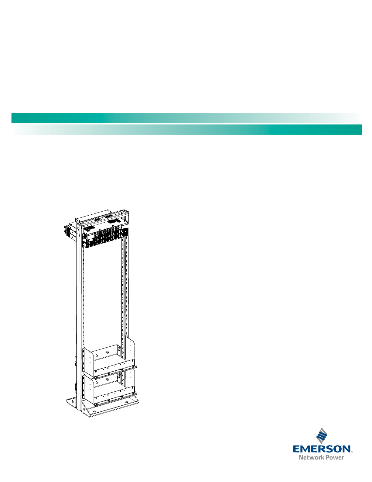
NetSure™ -48 VDC Power System
User Manual, UM582137200
(Revision A, January 11, 2017)
Specification Number: 582137200
™
Model Number: NetSure
5100
Page 2

NetSure™ -48 VDC Power System
User Manual, UM582137200
This page is intentionally blank.
Spec. No: 582137200 Document Code: U M582137200
Model No: NetSure™ 5100 Revision A, January 11, 2017
Page 3

NetSure™ -48 VDC Power System
[i]
User Manual, UM582137200
Table of Contents
Admonishments Used in this Document ................................................................................................................ ii
Important Safety Instructions .............................................................................................................................. iii
General Safety ........................................................................................................................................................iii
Voltages .................................................................................................................................................................iii
Battery ...................................................................................................................................................................iii
Personal Protective Equipment (PPE) ....................................................................................................................... v
Hazardous Voltage ................................................................................................................................................. v
Handling Equipment Containing Static Sensitive Components ................................................................................. v
Maintenance and Replacement Procedures ............................................................................................................. v
Static Warning ..................................................................................................................................................... vi
Customer Documentation Package ....................................................................................................................... 1
System Description ............................................................................................................................................... 1
Operating Procedures ........................................................................................................................................... 1
Controller and Rectifier ........................................................................................................................................... 1
ESTOP Function ...................................................................................................................................................... 2
Controller Battery Charge Current Limit Feature ...................................................................................................... 2
Local Controls and Indicators .................................................................................................................................. 2
Maintenance ......................................................................................................................................................... 2
System Maintenance Procedures ............................................................................................................................ 2
Adding a Rectifier ................................................................................................................................................... 2
Installing a Field Expansion Rectifier Shelf ................................................................................................................ 2
Troubleshooting and Repair .................................................................................................................................. 8
Contact Information ............................................................................................................................................... 8
Controller and Rectifier ........................................................................................................................................... 8
Controller Configuration ......................................................................................................................................... 8
System Troubleshooting Information ...................................................................................................................... 8
Replacement Information ....................................................................................................................................... 9
Replacement Procedures ........................................................................................................................................ 9
Replacing a Rectifier ........................................................................................................................................ 9
Replacing the NCU Controller .......................................................................................................................... 9
Replacing a Distribution Device ........................................................................................................................ 9
Circuit Card Replacement Procedures ............................................................................................................ 12
NetPerform™ Optimization Services ................................................................................................................... 17
Spec. No: 582137200 Document Code: U M582137200
Model No: NetSure™ 5100 Revision A, January 11, 2017
Page 4
NetSure™ -48 VDC Power System
[ii]
DANGER!
if not avoided. (ANSI, OSHA)
WARNING!
serious injury if not avoided. This admonition is not used for situations that pose a risk only to
equipment, software, data, or service. (ANSI)
CAUTION!
moderate injury if not avoided. (ANSI, OSHA) This admonition is not used for situations that pose a risk
only to equipment, data, or service, even if such use appears to
standards. (OSHA)
ALERT!
data, or service. (ISO)
ALERT!
software corruption, data loss, or service interruption. (ISO)
FIRE SAFETY!
locations of fire
SAFETY!
to a particular source of hazard or to fire safety. (ISO, ANSI, OSHA)
User Manual, UM582137200
Admonishments Used in this Document
Warns of a hazard the reader will be exposed to that will likely result in death or serious injury
D
an
g
er
Warns of a potential hazard the reader may be exposed to that could result in death or
W
ar
Caution
A
lert
Alert
Fi
re Safet
n
in
g
Warns of a potential hazard the reader may be exposed to that could result in minor or
be permitted in some of the applicable
Alerts the reader to an action that must be avoided in order to protect equipment, software,
Alerts the reader to an action that must be performed in order to prevent equipment damage,
Informs the reader of fire safety information, reminders, precautions, or policies, or of the
-fighting and fire-safety equipment. (ISO)
y
Informs the reader of general safety information, reminders, precautions, or policies not related
S
afety
Spec. No: 582137200 Document Code: U M582137200
Model No: NetSure™ 5100 Revision A, January 11, 2017
Page 5

NetSure™ -48 VDC Power System
[iii]
Danger
D
an
g
er
Warning
War
nin
g
D
anger
D
ange
r
User Manual, UM582137200
Important Safety Instructions
General Safety
DANGER!
YOU MUST FOLLOW APPROVED SAFETY PROCEDURES.
Performing the following procedures may expose you to
hazards. These procedures should be performed by
qualified technicians familiar with the hazards
associated with this type of equipment. These hazards
may include shock, energy, and/or burns. To avoid
these hazards:
a) The tasks should be performed in the order
indicated.
b) Remove watches, rings, and other metal objects.
c) Prior to contacting any uninsulated surface or
termination, use a voltmeter to verify that no
voltage or the expected voltage is present. Check
for voltage with both AC and DC voltmeters prior to
making contact.
d) Wear eye protection.
e) Use certified and well maintained insulated tools.
Use double insulated tools appropriately rated for
the work to be performed.
Voltages
AC Input Voltages
DC Output and Battery Voltages
DANGER! This system produces DC power and may
have a battery source connected to it. Although the DC
voltage is not hazardously high; the rectifiers and/or
battery can deliver large amounts of current. Exercise
extreme caution not to inadvertently contact or have
any tool inadvertently contact an output terminal or
battery terminal or exposed wire connected to an
output terminal or battery terminal. NEVER allow a
metal object, such as a tool, to contact more than one
termination or battery terminal at a time, or to
simultaneously contact a termination or battery
terminal and a grounded object. Even a momentary
short circuit can cause sparking, explosion, and injury.
DANGER! Follow local lockout/tagout procedures to
ensure DC branch circuit protection devices remain deenergized during installation at loads, as required.
Battery
Refer to the battery manufacturer documentation for specific
battery safety instructions. The following are general guidelines.
WARNING! Correct polarity must be observed when
connecting battery leads.
DANGER! This system operates from AC input voltage
capable of producing fatal electrical shock. AC input
power must be completely disconnected from the
branch circuits wiring used to provide power to the
system before any AC electrical connections are made.
Follow local lockout/tagout procedures to ensure
upstream branch circuit breakers remain de-energized
WARNING! Special safety precautions are required for
procedures involving handling, installing, and servicing
batteries. Observe all battery safety precautions in this
manual and in the battery instruction manual. These
precautions should be followed implicitly at all times.
during installation. DO NOT apply AC input power to
the system until all electrical connections have been
completed and checked.
Spec. No: 582137200 Document Code: U M582137200
Model No: NetSure™ 5100 Revision A, January 11, 2017
Page 6

NetSure™ -48 VDC Power System
[iv]
W
a
rn
in
g
D
a
ng
er
Alert
User Manual, UM582137200
WARNING! A battery can present a risk of electrical
shock and high short circuit current. Servicing of
batteries should be performed or supervised only by
properly trained and qualified personnel knowledgeable
about batteries and the required precautions.
The following precautions should be observed when
working on batteries:
• Remove watches, rings, and other metal objects.
• Eye protection should be worn to prevent injury
from accidental electrical arcs.
• Use certified and well maintained insulated tools.
Use double insulated tools appropriately rated for
the work to be performed. Ensure that wrenches
with more than one working end have only one end
exposed.
• Do not lay tools or metal parts on top of batteries.
• Disconnect charging source prior to connecting or
disconnecting battery terminals.
• Risk of explosion if battery is replaced with an
incorrect type or if polarity is reversed.
Recommended to replace batteries with the same
manufacturer and type, or equivalent.
• Dispose of used batteries according to the
instructions provided with the batteries. Do not
dispose of batteries in a fire. They may explode.
• ALWAYS FOLLOW THE BATTERY MANUFACTURER’S
RECOMMENDATIONS AND SAFETY INSTRUCTIONS.
DANGER! This equipment may be used in conjunction
with lead-acid batteries. Working near lead-acid
batteries is dangerous!
In addition to the hazard of electric shock, gas produced
by batteries can be explosive and sulfuric acid can cause
severe burns.
• Do not open or mutilate batteries. Released
electrolyte is harmful to the skin and eyes, and is
toxic.
• Batteries contain sulfuric acid.
• Batteries generate explosive gases during normal
operation. Systems containing batteries should
never be installed in an airtight room or space.
Only install in a ventilated environment.
• Batteries are an energy source that can produce
high amounts of electrical current.
FOR THESE REASONS, IT IS OF CRITICAL IMPORTANCE
THAT YOU READ THESE INSTRUCTIONS AND FOLLOW
THEM EXACTLY.
WHEN WORKING WITH LEAD-ACID BATTERIES:
• Follow the recommended PPE requirements per the
SDS for the battery to be used.
• If battery acid enters your eye, immediately flush
your eye with running cold water for at least 15
minutes. Get medical attention immediately.
• If battery acid contacts skin or clothing, wash
immediately with soap and water.
ALERT! Performing maintenance and/or
troubleshooting procedures may interrupt power to the
loads, if battery reserve is not sufficient.
Spec. No: 582137200 Document Code: U M582137200
Model No: NetSure™ 5100 Revision A, January 11, 2017
Page 7
NetSure™ -48 VDC Power System
[v]
CAUTION!
NOTE:
Danger
Alert
Caution
Danger
User Manual, UM582137200
Personal Protective Equipment (PPE)
DANGER! ARC FLASH AND SHOCK HAZARD.
Appropriate PPE and tools required when working on
this equipment. An appropriate flash protection
boundary analysis should be done determine the
“hazard/risk” category, and to select proper PPE.
This product is intended only for installation in a
Restricted Access Location.
Only authorized and properly trained personnel should
be allowed to install, inspect, operate, or maintain the
equipment.
Do not work on LIVE parts. If required to work or
operate live parts, obtain appropriate Energized Work
Permits as required by the local authority, per NFPA 70E
“Standard for Electrical Safety in the Workplace”.
Hazardous Voltage
DANGER! Hazard of electrical shock. More than one
disconnect may be required to de-energize the system
before servicing.
Handling Equipment Containing Static Sensitive Components
ALERT! Installation or removal of equipment containing
static sensitive components requires careful handling.
Before handling any equipment containing static
sensitive components, read and follow the instructions
contained on the Static Warning Page.
Maintenance and Replacement Procedures
requires removal or installation of hardware, use caution
to ensure no hardware is dropped and left inside the
unit; otherwise service interruption or equipment
damage may occur.
requires removal of existing hardware, retain all hardware
for use in subsequent steps, unless otherwise directed.
When performing any step in procedures that
When performing any step in procedures that
Spec. No: 582137200 Document Code: U M582137200
Model No: NetSure™ 5100 Revision A, January 11, 2017
Page 8

NetSure™ -48 VDC Power System
[vi]
User Manual, UM582137200
Static Warning
This equipment contains static sensitive components. The warnings listed below must be observed to prevent damage to these
components. Disregarding any of these warnings may result in personal injury or damage to the equipment.
1. Strictly adhere to the procedures provided in this document.
2. Before touching any equipment containing static sensitive components, discharge all static electricity from yourself by wearing
a wrist strap grounded through a one megohm resistor. Some wrist straps, such as Part Number 631810600, have a built-in one
megohm resistor; no external resistor is necessary. Read and follow wrist strap manufacturer’s instructions outlining use of a
specific wrist strap.
3. Do not touch traces or components on equipment containing static sensitive components.
Handle equipment containing static sensitive components only by the edges that do not have connector pads.
4. After removing equipment containing static sensitive components, place the equipment only on conductive or anti-static
material such as conductive foam, conductive plastic, or aluminum foil. Do not use ordinary Styrofoam
5. Store and ship equipment containing static sensitive components only in static shielding containers.
6. If necessary to repair equipment containing static sensitive components, wear an appropriately grounded wrist strap, work on a
conductive surface, use a grounded soldering iron, and use grounded test equipment.
™
or ordinary plastic.
Spec. No: 582137200 Document Code: U M582137200
Model No: NetSure™ 5100 Revision A, January 11, 2017
Page 9

NetSure™ -48 VDC Power System
[1 of 17]
NOTE:
User Manual, UM582137200
Customer Documentation Package
This document (UM582137200) provides User Instructions for
-48 VDC Power System Model NetSure™ 5100, Spec. No.
582137200.
The complete Customer Documentation Package consists of…
NetSure™ -48 VDC Power System Installation Manual
• Power System Installation Instructions: IM582137200
NetSure™ NCU Controller User Manual
• NCU Controller User Instructions: UM1M830BNA
USB Drive with All Customer Documentation
• Power System Installation Instructions: IM582137200
• Power System User Instructions: UM582137200
• Power System “System Application Guide”:
SAG582137200
• NCU Controller User Instructions: UM1M830BNA
• Rectifier Instructions: UM1R482000e3
• Engineering Drawings
• Also provided on the USB drive is a Controller
Configuration Drawing (C-drawing) and the controller
configuration files loaded into the controller as shipped.
Controller
NCU (NetSure Control Unit): The controller provides power system
control (including optional low voltage battery disconnect [LVBD]
and low voltage load disconnect [LVLD] control), rectifier control
(including a charge control function), metering functions,
monitoring functions, local/remote alarm functions, and
connections for binary inputs and programmable relay outputs via
a controller interface board. The controller also supports rectifier
temperature compensation if the system is equipped with a
temperature probe(s). Temperature probe(s) may also be
designated to monitor ambient temperature and/or battery
temperature. The controller also provides data acquisition, system
alarm management, and advanced battery and energy
management. The controller contains a color TFT display and
keypad for local access. The controller provides an Ethernet port
and comes with comprehensive webpages for remote access. The
controller has optional SNMP v3 capability for remote system
management. The controller supports software upgrade via its
USB port. Refer to the NCU Controller Instructions
(UM1M830BNA) for more information.
Rectifier Modules
The system contains rectifier modules, which provide load power,
battery float current, and battery recharge current during normal
operating conditions. Refer to the Rectifier Instructions
(UM1R482000e3) for more information.
Distribution Unit
For factory settings of all configurable controller parameters, refer
to the Configuration Drawing (C-drawing) supplied with your
power system.
System Description
-48 VDC @ up to 150 Amperes Power System
The NetSure™ 5100 DC Power System is an integrated power
system containing rectifiers, intelligent control, metering,
monitoring, and distribution.
This power system is designed to power a load while charging a
positive grounded battery. This power system is capable of
operating in a batteryless installation or off battery for
maintenance purposes. The power system is designed for
operation with the positive output grounded.
The NetSure 5100 consists of the following components mounted
in a 19” or 23” wide relay rack or cabinet rack. Wall mounting
options are also available.
Spec. No: 582137200 Document Code: U M582137200
Model No: NetSure™ 5100 Revision A, January 11, 2017
Various distribution unit options are available. See
SAG582137200 for descriptions. The distribution unit can be
equipped with an optional Low Voltage Battery Disconnect (LVBD)
or Low Voltage Load Disconnect (LVLD) contactor. The
distribution unit provides DC distribution through circuit breakers
and/or fuses.
Operating Procedures
Controller and Rectifier
For operation instructions on these units, refer to the following
documents.
• NCU Controller Instructions (UM1M830BNA)
The controller’s default “User Name” is "admin"
and the default “Password” is “640275”.
• Rectifier Instructions (UM1R482000e3)
Page 10

NetSure™ -48 VDC Power System
[2 of 17]
DANGER!
NOTE:
NOTE:
Da
ng
e
r
User Manual, UM582137200
ESTOP Function
If an ESTOP switch is wired to the IB2 Controller Interface Board,
customer-furnished system ground applied to terminal Digital
Input #8 (+) activates the ESTOP function. The ESTOP function
shuts down and locks out the rectifiers and opens the LVD’s. When
the ESTOP signal is removed, LVD’s close after the “LVD Reconnect
Delay” has elapsed (customer configurable via the controller) (if
battery is present or after the rectifiers are restarted). To restart
the rectifiers, turn input power to the rectifiers OFF, wait 30
seconds or more (until the LEDs on the modules extinguish), then
turn input power to the rectifiers ON.
Controller Battery Charge Current Limit Feature
Functionality: After a failure of the input source (commercial AC)
or when some battery cells are permanently damaged, the current
to the batteries can be quite extensive. To avoid overheating or
further damages to the battery, the controller can be programmed
to limit the battery current to a preset level by limiting the
charging voltage of the rectifiers. Should the battery current still
exceed a higher preset value, an alarm is issued.
The controller limits the current going to the batteries based on
the “Battery Current Limit” set point which is a percentage of the
battery capacity in C10. For example, 0.1C10 would mean 10% of
the battery capacity.
Refer to the NCU Controller Instructions (UM1M830BNA) to
program this feature. Battery charge current is limited to the value
set in the controller, as long as battery voltage is above 47 VDC.
Table 1. Maintenance Procedures to be Performed at 6-Month
Intervals
Procedure Referenced In
Check ventilation openings for
obstructions such as dust, papers,
manuals, etc.
Inspect and tighten all installer's
connections.
--
IM582137200
Adding a Rectifier
To increase system current capacity, a rectifier module can easily
be added if an empty rectifier module mounting position is
available.
Refer to Rectifier Instructions UM1R482000e3 for a rectifier
installation procedure.
Installing a Field Expansion Rectifier Shelf
presented at the front of this document.
performed.
Adhere to the “Important Safety Instructions”
Refer to Figure 1 and Figure 2 as this procedure is
Local Controls and Indicators
Controller and Rectifier
Refer to the controller and rectifier instructions for descriptions of
the local controls and indicators located on these units.
Maintenance
System Maintenance Procedures
It is recommended to perform the maintenance procedures listed
in Table 1 every 6-months to ensure continual system operation.
Spec. No: 582137200 Document Code: U M582137200
Model No: NetSure™ 5100 Revision A, January 11, 2017
Procedure
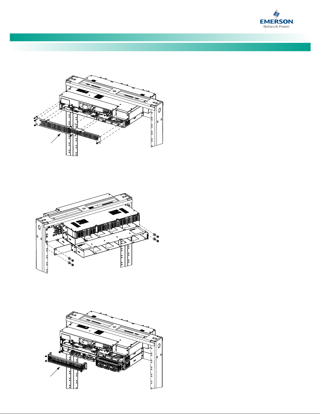
1. Remove the rear shield from the main module mounting
assembly. This shield will not be re-used.
2. When the main module mounting assembly is configured
with the front AC option, replace the mounting angle on
the left side (as viewed from the front) of the expansion
module mounting assembly with the longer mounting
angle shipped loose with the expansion module
mounting assembly.
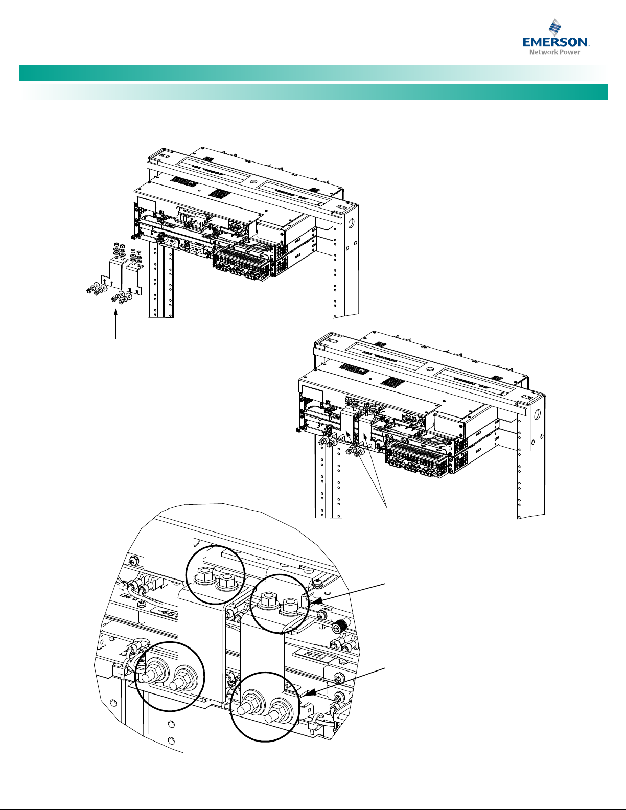
3. Install the expansion module mounting assembly directly
below the main module mounting assembly. Use the
mounting hardware provided with the expansion module
mounting assembly. See Figure 1. Refer also to Figure 1
for hardware build-up and recommended torque.
Install (orient) the ground washers so the teeth
dig into the mounting angles for a secure ground
connection.
Page 11

NetSure™ -48 VDC Power System
[3 of 17]
NOTE:
NOTE:
User Manual, UM582137200
4. Remove the rear shield from the expansion module
5. Remove the hardware from the main module mounting
6. Loosen the hardware from the expansion module
7. Slide the busbars provided with the expansion module
Compliance with Telcordia GR-1089-CORE
requires that prior to mounting the system to the
equipment rack:
• All paint must be removed from the front surface of
each equipment rack rail where it mates with a shelfmounting bracket, so that good metal-to-metal
contact can be established between the shelf and
rack.
• The shelf-to-rack mating surfaces must be cleaned.
• Electrical anti-oxidizing compound must be applied
to the shelf-to-rack mating surfaces.
mounting assembly.
Apply electrical anti-oxidizing compound to
busbar mating surfaces before performing the next step.
assembly’s -48V and return busbars.
mounting assembly’s -48V and return busbars.
mounting assembly into position. These busbars are
installed between the busbar studs on the expansion
module mounting assembly and the busbar studs on the
main module mounting assembly. Secure these busbars
to the expansion module mounting assembly with the
hardware provided with the expansion module mounting
assembly. Secure these busbars to the main module
mounting assembly with the hardware provided with the
main module mounting assembly. Refer to Figure 1 for
hardware build-up and torque.
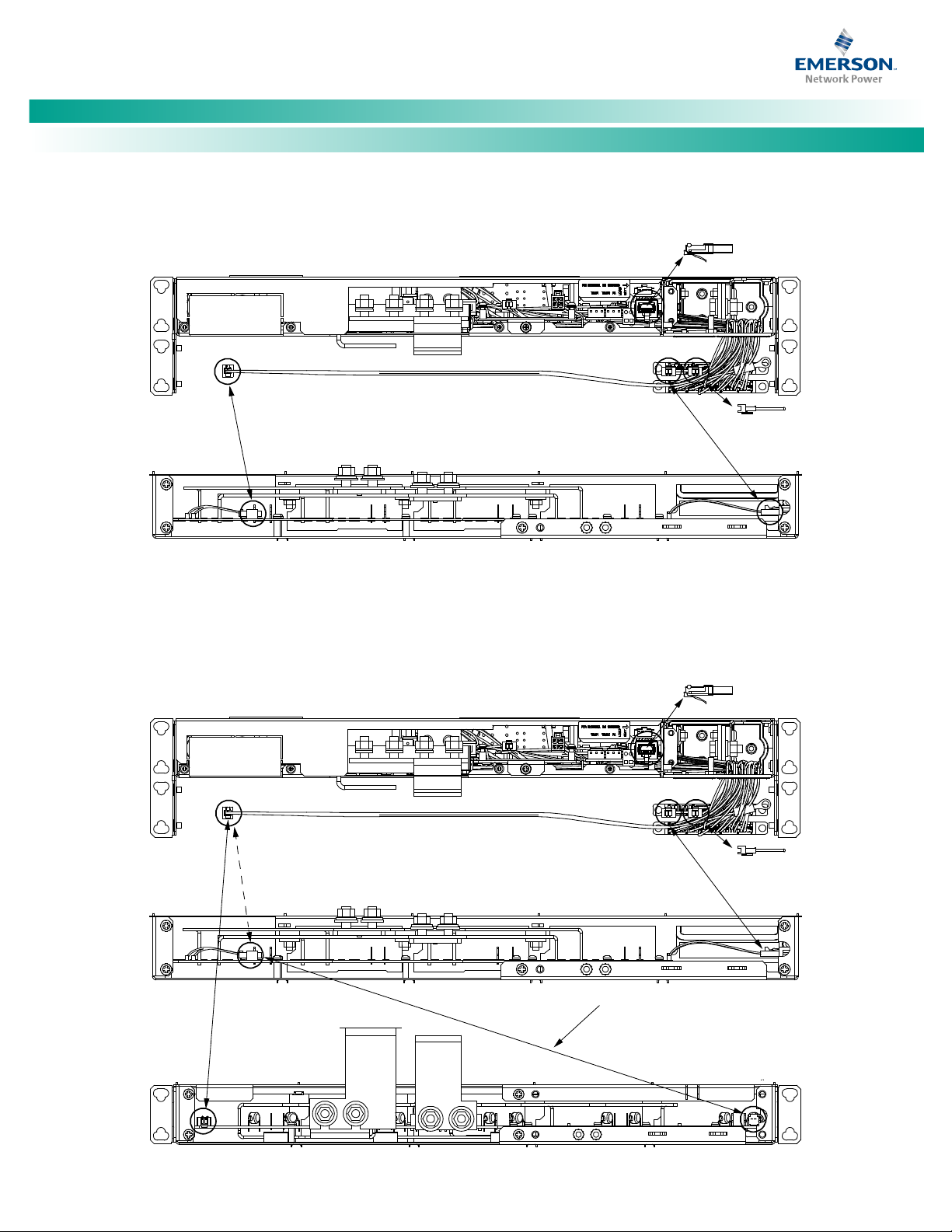
8. Disconnect the cable coming from the distribution unit
that is connected to the left side (as viewed from the
rear) connector on the main module mounting assembly.
Connect this cable to the left side (as viewed from the
rear) connector on the expansion module mounting
assembly. See Figure 2.
9. Connect the cable provided with the expansion module
mounting assembly between the left side (as viewed
from the rear) connector on the main module mounting
assembly and the right side (as viewed from the rear)
connector on the expansion module mounting assembly.
See Figure 2.
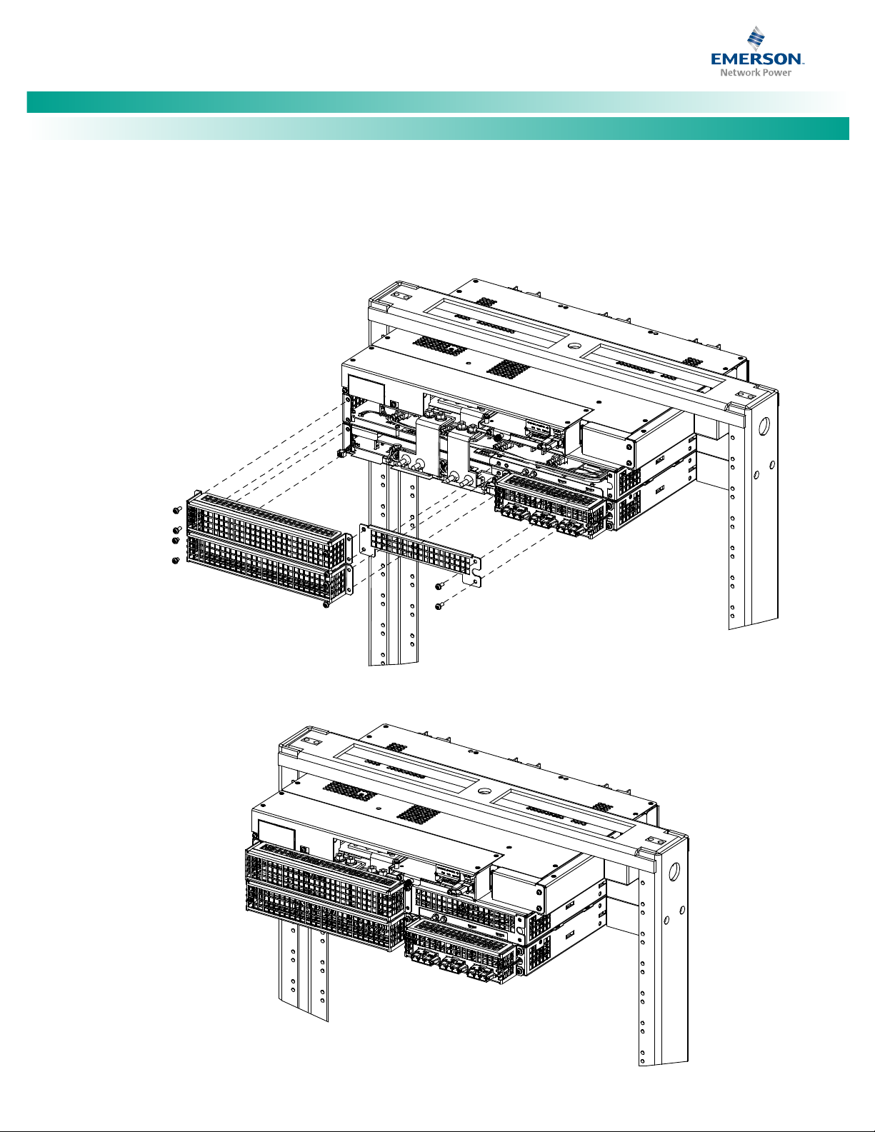
10. Install the new rear shields supplied with the expansion
module mounting assembly to the rear of the main
module mounting assembly. See Figure 1.
11. Re-install the busbar shield previously removed from the
expansion module mounting assembly. See Figure 1.
12. Refer to the Power System Installation Instructions
(IM582137200) and connect input power to the
expansion module mounting assembly.
13. Refer to the Power System Installation Instructions
(IM582137200) and install rectifier modules into the
expansion module mounting assembly as required.
Spec. No: 582137200 Document Code: U M582137200
Model No: NetSure™ 5100 Revision A, January 11, 2017
Page 12
NetSure™ -48 VDC Power System
[4 of 17]
1. Remove rear shield from the
main module mounting assembly.
This shield will not be reused.
3. Install the expansion module
mounting assembly into the rack.
4. Remove rear shield from the
expansion module mounting assembly.
MOUNTING HARDWARE
12-24 x 3/4" Thread Forming
Hex Head Screw
No. 10/12 Ground Washer
Torque: 65 in-lbs.
Install the ground washers so the
teeth make contact with the metal
on the mounting angles.
23” Front AC Option Shown.
19” Rear AC Option Similar.
Rear
Shield
Rear
Shield
Rear
Rear
Front
2. When the main module mounting
assembly is configured with the
front AC option, replace the mounting
angle on the left side of the expansion
module mounting assembly with the
longer mounting angle shipped loose
with the expansion module mounting
assembly.
User Manual, UM582137200
Figure 1. Installing a Field Expansion Rectifier Shelf (cont’d on next page)
Spec. No: 582137200 Document Code: U M582137200
Model No: NetSure™ 5100 Revision A, January 11, 2017
Page 13
NetSure™ -48 VDC Power System
[5 of 17]
Busbars slid into position.
Rear
Installed View
Hardware Build-Up:
Busbar
M6 Flat Washer
M6 Lock Washer
M6 Hex Nut
Torque to 52 in-lbs.
Hardware Build-Up:
Busbar
M6 Flat Washer
M6 Lock Washer
M6 Hex Nut
Torque to 52 in-lbs.
5. Install the busbars provided
with the expansion module
mounting assembly between the
shelves. Torque to52 in-lbs.
Do this by removing the hardware from
the main shelf busbars, loosening the
hardware on the expansion shelf busbars,
and sliding the busbars into position.
Apply electrical anti-oxidizing
compound to busbar mating surfaces.
Rear
Busbars
User Manual, UM582137200
Figure 1. Installing a Field Expansion Rectifier Shelf (cont’d from previous page, cont’d on next page)
Spec. No: 582137200 Document Code: U M582137200
Model No: NetSure™ 5100 Revision A, January 11, 2017
Page 14
NetSure™ -48 VDC Power System
[6 of 17]
Rear
Installed View
6. Install the new rear shields supplied
with the expansion module mounting
assembly to the main module
mounting assembly.
7. Re-install the rear shield (previously
removed) onto the expansion module
mounting assembly.
Rear
User Manual, UM582137200
Figure 1. Installing a Field Expansion Rectifier Shelf (cont’d from previous page)
Spec. No: 582137200 Document Code: U M582137200
Model No: NetSure™ 5100 Revision A, January 11, 2017
Page 15
NetSure™ -48 VDC Power System
[7 of 17]
Components removed in
illustration for clarity only.
Distribution Unit
List 01 Main Shelf
Distribution Unit
List 01 Main Shelf
List 02 Expansion Shelf
Cable P/N 555716
Provided with
Expansion Shelf
(Field Installed)
Exploded View Shown to
Illustrate Wire Connections Only
Termination Resistor
P/N 548398
Termination
Resistor P/N
RPM628350/2
Distribution Unit
with List 01
Distribution Unit
with List 01 and 02
Termination Resistor
P/N 548398
These Are Factory
Connected Together
These Are Factory
Connected Together
These Are Factory
Connected Together
Connect
These
Together
DISCONNECT
These
Connectors
Termination
Resistor P/N
RPM628350/2
User Manual, UM582137200
Figure 2. Installing a Field Expansion Rectifier Shelf - Controller CAN Bus
Spec. No: 582137200 Document Code: U M582137200
Model No: NetSure™ 5100 Revision A, January 11, 2017
Page 16

NetSure™ -48 VDC Power System
[8 of 17]
NOTE:
Active Alarm
Alarm History
User Manual, UM582137200
Troubleshooting and Repair
Contact Information
Support contact information is provided at the back of this
document.
Controller and Rectifier
For troubleshooting and repair instructions on these units, refer to
the following documents.
• NCU Controller Instructions (UM1M830BNA)
• Rectifier Instructions (UM1R482000e3)
Controller Configuration
If any controller configuration settings were changed, refer to the
NCU Controller Instructions (UM1M830BNA) and save a copy of
the configuration file. This file can be used to restore the
controller settings, if required, at a later date.
System Troubleshooting Information
This system is designed for ease in troubleshooting and repair. The
various indicators as described in “Local Controls and Indicators”
on page 2 and in the controller and rectifier instructions are
designed to isolate failure to a specific element. Once the faulty
element has been identified, refer to “Replacement Information”
on page 9 and “Replacement Procedures” on page 9.
Troubleshooting Alarm Conditions on the Controller
Provided on a USB drive furnished with the system
is a Controller Configuration Drawing (C-drawing) and
the controller configuration files loaded into the
controller as shipped.
setpoint will be 100% of the combined capacity including the new
rectifier module.
If a rectifier module is removed from the system (and the Rect
Comm Fail is cleared), the current limit point will remain
unchanged unless the capacity of the remaining rectifiers is not
sufficient to maintain this current limit point. If that happens, the
current limit point will automatically decrease to the maximum
(121% of the remaining rectifiers).
It is recommended that the current limit point be checked
whenever a rectifier is added to or removed from the power
system.
When setting total rectifier current limit, the set point to each
rectifier is the total set point divided by the number of rectifiers.
For example, if the system contains five rectifiers and the current
limit is set to 150 amps then each rectifier has a current limit set
point of 30 amps. If one or more rectifiers are removed or fails it
will take several seconds for the individual set points to the
remaining rectifiers to be reset. In the example given, if one
rectifier is removed the current limit set point will drop to 120
amps (30 amps times four remaining rectifiers) until the controller
can send updated set points to the remaining rectifiers. This takes
a couple communication cycles (several seconds) after which each
rectifier would have a new set point of 37.5 amps for a total of 150
amps. The total current limit of the rectifiers should not be set
such that the loss of the redundant rectifiers will cause this
temporary set point to drop below the actual maximum expected
load. If batteries are used on the rectifier output, the batteries
should support the load until the current limit set points can be reestablished due to loss of a rectifier.
Refer to the NCU Controller Instructions (UM1M830BNA) for a
procedure.
The controller displays alarm conditions as listed in the “Resolving
Alarms” section of the controller’s User Manual. Programmable
external alarm relays are also available. Refer to the System
Installation Instructions (IM582137200) and the Controller
Configuration Drawing (C-drawing) supplied with your power
system documentation for your alarm relay configurations.
The controller’s
User to view alarm details. Refer to the NCU Controller
Instructions (UM1M830BNA) to access these menus.
Checking the Controller’s Current Limit Point after Adding or
Removing a Rectifier
If a rectifier module is added; the respective current limit point in
amps will automatically increase to maintain the same percentage.
For example, if the current limit was set to 100% of combined
capacity and a rectifier module is added, the new current limit
Spec. No: 582137200 Document Code: U M582137200
Model No: NetSure™ 5100 Revision A, January 11, 2017
and
submenus allow the
Clearing a Rectifier Communications Fail Alarm after Removing
a Rectifier
If a rectifier module is removed from the system, a rectifier
communications failure alarm is generated. If the rectifier module
will not be replaced, the alarm should be cleared.
Refer to the NCU Controller Instructions (UM1M830BNA) for a
procedure.
Clearing a Rectifier Lost Alarm
If the controller resets while a rectifier communications fail alarm is
active, the rectifier communications fail alarm is replaced with a
rectifier lost alarm.
Refer to the NCU Controller Instructions (UM1M830BNA) for a
procedure to clear the alarm.
Page 17

NetSure™ -48 VDC Power System
[9 of 17]
DANGER!
D
an
ge
r
User Manual, UM582137200
Replacement Information
Replacement Assemblies
When a trouble symptom is localized to a faulty rectifier,
controller, or system circuit card; that particular device or circuit
card should be replaced in its entirety. No attempt should be
made to troubleshoot or repair individual components on any
rectifier, controller, or circuit card.
Refer to System Application Guide SAG582137200 for
replacement part numbers.
Replacement Procedures
presented at the front of this document.
REPLACING A RECTIFIER
Refer to the Rectifier Instructions (UM1R482000e3) for a rectifier
replacement procedure. Refer also to “System Troubleshooting
Information” on page 8.
The rectifier being replaced is assigned by the NCU the lowest
available identification number. If desired, you can change the
identification number, see “Configuring the NCU Identification of
Rectifiers” in the separate Power System Installation Manual
(IM582137200).
REPLACING THE NCU CONTROLLER
Adhere to the “Important Safety Instructions”
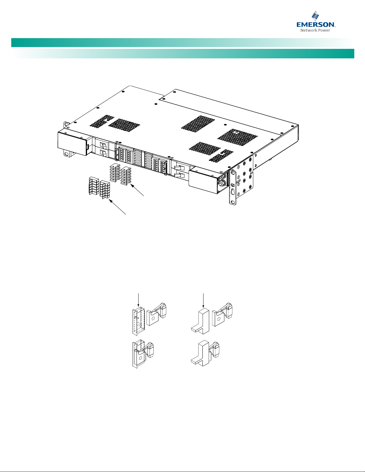
Replacing a GMT Distribution Fuse
Procedure
1. Refer to Figure 3 and replace the fuse. Ensure a safety
fuse cover is installed on the replacement fuse, as shown
in Figure 4.
2. Verify no alarms are active.
Replacing a Bullet Nose Circuit Breaker
Procedure
1. Operate the defective circuit breaker to the OFF position.
2. Gently rock the defective circuit breaker back and forth
while pulling firmly outward until the breaker is free from
the distribution unit.
3. Ensure that the replacement circuit breaker is in the OFF
position, and is of the correct rating.
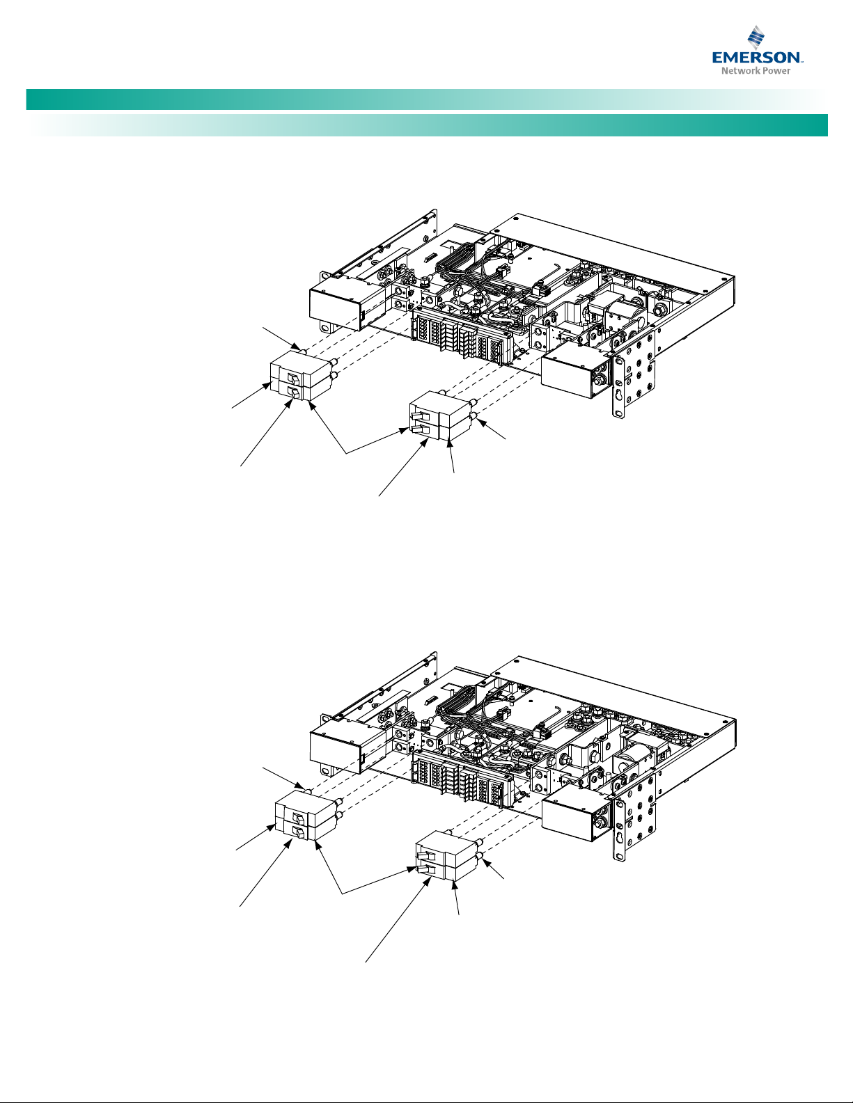
4. Orient the replacement circuit breaker as shown in Figure
5 or Figure 6. Insert the terminals on the rear of the
circuit breaker into their corresponding sockets on the
distribution unit. Ensure the alarm contact on the back of
the circuit breaker makes contact with the alarm terminal
on the distribution unit. Push distribution device in firmly
until fully seated in the distribution unit.
Refer to the NCU Controller Instructions (UM1M830BNA) for a
controller replacement procedure.
REPLACING A DISTRIBUTION DEVICE
5. Operate the replacement circuit breaker to the ON
position.
6. Verify no alarms are active.
Replace distribution devices with the same type and rating. Refer
to System Application Guide SAG582137200 for part numbers.
Spec. No: 582137200 Document Code: U M582137200
Model No: NetSure™ 5100 Revision A, January 11, 2017
Page 18
NetSure™ -48 VDC Power System
[10 of 17]
GMT Fuse
Safety Cover
Front
List BA shown,
List BC, BF, LC, NA, NC, NF similar.
Safety Cover
P/N 248898700
(GMT-X)
Safety Cover
P/N 102774
(GMT-Y)
User Manual, UM582137200
Figure 3. GMT Distribution Fuse Replacement (List BA, BC, BF, LC, NA, NC, NF)
Figure 4. Installation of Safety Fuse Covers
Spec. No: 582137200 Document Code: U M582137200
Model No: NetSure™ 5100 Revision A, January 11, 2017
Page 19
NetSure™ -48 VDC Power System
[11 of 17]
List BA shown, List NA similar.
Battery Disconnect
Circuit Breakers
Front
Components removed in illustration for clarity only.
Load Distribution
Circuit Breakers
Ins
ert
thes
e
t
erm
inals
into
corresponding
sockets on
dist
rib
uti
on unit
.
I
ns
e
rt
th
e
se
terminals
i
nt
o
corresponding
so
c
kets
on
distribution unit .
Shorter Si
de
of Breaker
Longer Side
of Breaker
Lo
nger
Sid
e
of Breaker
Turn circuit breaker off before installing.
OFF
Position
Towards
Center
List BC shown, List LC, NC similar.
Load Disconnect
Circuit Breakers
Front
Components removed in illustration for clarity only.
Load Distribution
Circuit Breakers
In
sert these
terminals into
corresponding
sockets on
distribution unit .
Insert these
terminals into
corresponding
sockets on
distribution unit .
Shorter Side
of Breaker
OFF
Position
Towards
Center
Longer Side
of Breaker
Longer Side
of Breaker
Turn circuit breaker off before installing.
User Manual, UM582137200
Figure 5. Replacing a Bullet Nose Circuit Breaker (List BA,NA)
Figure 6. Replacing a Bullet Nose Circuit Breaker (List BC, LC, NC)
Spec. No: 582137200 Document Code: U M582137200
Model No: NetSure™ 5100 Revision A, January 11, 2017
Page 20
NetSure™ -48 VDC Power System
[12 of 17]
DANGER!
WARNING!
NOTE:
WARNING!
NOTE:
WARNING!
DANGER!
W
ar
ni
n
g
D
a
n
g
e
r
Wa
rning
Wa
rning
Dang
er
User Manual, UM582137200
CIRCUIT CARD REPLACEMENT PROCEDURES
Adhere to the “Important Safety Instructions”
presented at the front of this document.
Circuit cards used in this power system
contain static-sensitive devices. Read the Static
Warning at the front of this document before
performing any of the following procedures.
General
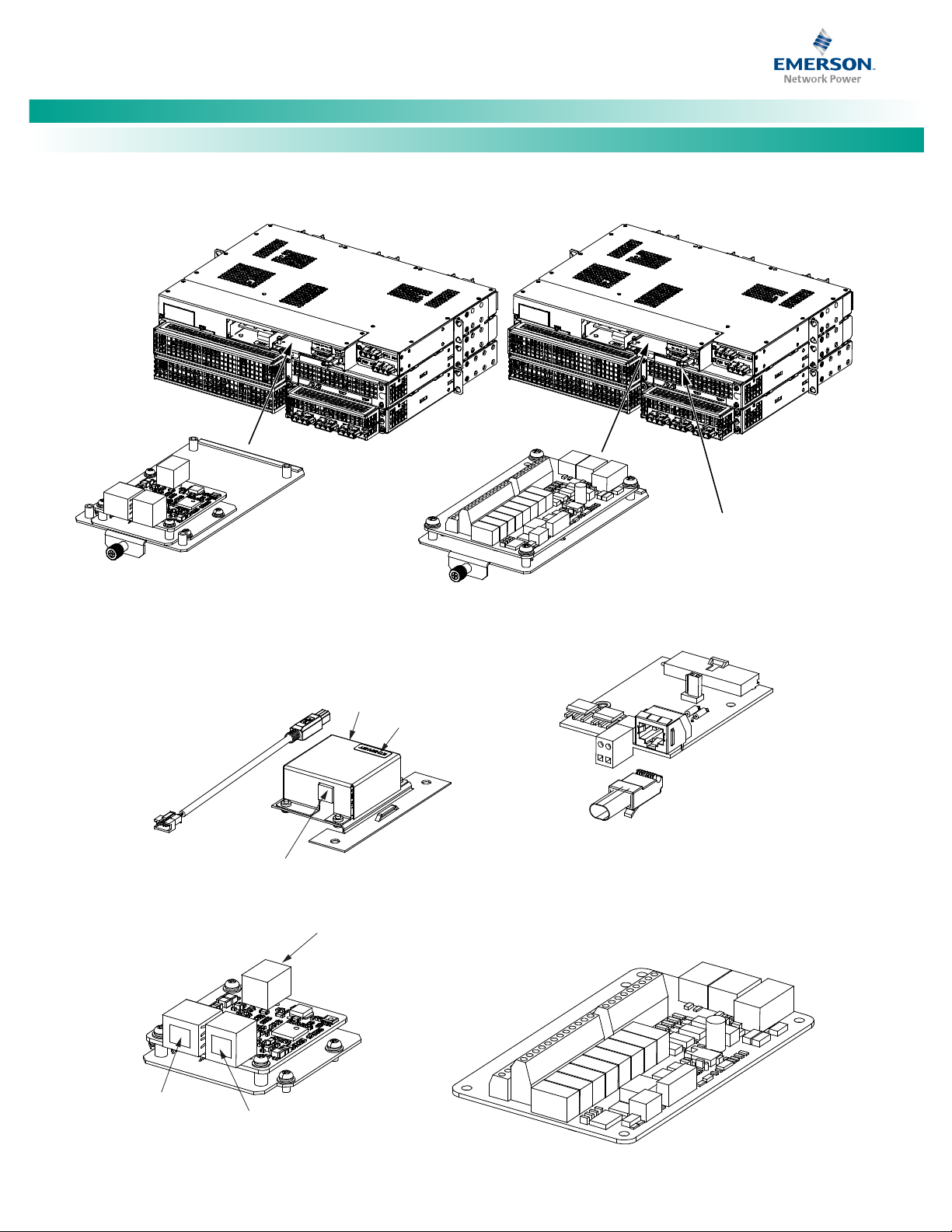
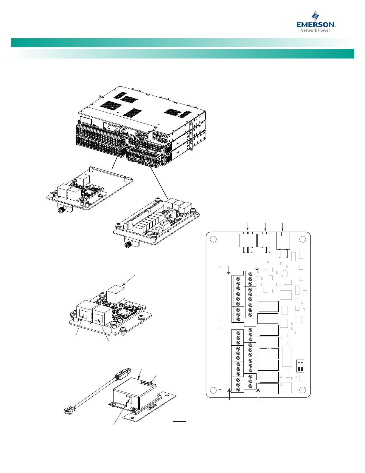
The following circuit card replacement procedures can be
performed with the system operating. Refer to Figure 7 for circuit
card locations.
Replacing the System Interface Circuit Card
Procedure
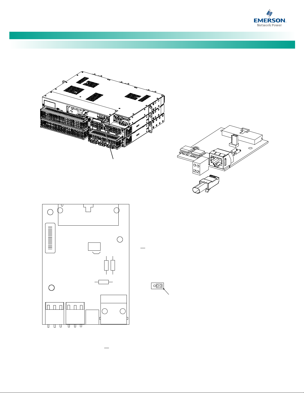
Refer to Figure 8 as this procedure is performed.
1. Performing this procedure may activate external alarms.
Do one of the following. If possible, disable these alarms.
If these alarms cannot be easily disabled, notify the
appropriate personnel to disregard any future alarms
associated with this system while the procedure is being
performed.
Damage to the circuit card may result if the
next step is not followed.
2. Connect an approved grounding strap to your wrist.
Attach the other end to a suitable ground.
3. Remove the rear/top cover from the distribution unit to
access the circuit card.
8. Orient the replacement circuit card over its mounting
position, and secure with the screws removed from the
old circuit card.
9. Plug all connectors removed from the old circuit card into
the same position on the replacement circuit card.
10. Reinstall the rear/top cover to the distribution unit.
11. Remove the grounding wrist strap.
12. Enable the external alarms, or notify appropriate
personnel that this procedure is finished.
13. Ensure that there are no local or remote alarms active on
the system.
Replacing the IB2 (Controller Interface Board) (if furnished)
Procedure
Refer to Figure 9 as this procedure is performed.
1. Performing this procedure may activate external alarms.
Do one of the following. If possible, disable these alarms.
If these alarms cannot be easily disabled, notify the
appropriate personnel to disregard any future alarms
associated with this system while the procedure is being
performed.
Damage to the circuit card may result if the
next step is not followed.
2. Connect an approved grounding strap to your wrist.
Attach the other end to a suitable ground.
3. Loosen the screw securing the slide out tray on the rear
of the distribution unit. Slide the tray out to access the
circuit card.
4. Carefully label the connectors plugged into the circuit
card. These connectors must be plugged into the same
connectors on the replacement circuit card.
5. Unplug all connectors plugged into the circuit card.
6. Remove the circuit card from the distribution unit by
removing the screws securing it.
7. In this step, ensure you do not intermix the old and
replacement circuit cards. Set the shorting jumper on
the replacement circuit card to match the location on the
old circuit card. Jumper settings are documented in the
“Setting Jumper and Switch Options” section of the
Power System Installation Instructions (IM582137200).
4. Carefully label the wires connected to the customer
connection terminal blocks on the circuit card. These
wires must be connected to the same terminals on the
replacement circuit card.
5. Carefully label the connectors plugged into the circuit
card. These connectors must be plugged into the same
connectors on the replacement circuit card.
In the next step, external alarm wiring may be
energized from an external source. DO NOT allow bare
wire ends to contact any grounded or energized object.
6. Remove the external wiring from the customer
connection terminal blocks. DO NOT allow the bare wire
end to contact any grounded or energized object. Isolate
Spec. No: 582137200 Document Code: U M582137200
Model No: NetSure™ 5100 Revision A, January 11, 2017
Page 21

NetSure™ -48 VDC Power System
[13 of 17]
DANGER!
NOTE:
WARNING!
Local Menu Navigation:
Web Menu Navigation:
D
a
ng
er
Wa
r
ni
ng
User Manual, UM582137200
the wire end with electrical tape. Repeat for each wire to
be removed.
7. Unplug all connectors plugged into the circuit card.
8. Remove the circuit card from the distribution unit by
removing the screws securing it to the slide out tray.
9. In this step, ensure you do not intermix the old and
replacement circuit cards. Set the switch on the
replacement circuit card to the same setting as the old
circuit card. Switch settings are documented in the
“Setting Jumper and Switch Options” section of the
Power System Installation Instructions (IM582137200).
10. Orient the replacement circuit card over its mounting
position, and secure with the screws removed from the
old circuit card.
11. Plug all connectors removed from the old circuit card into
the same position on the replacement circuit card.
In the next step, external alarm wiring may be
energized from an external source. DO NOT allow bare
wire ends to contact any grounded or energized object.
12. Reconnect the external wiring to the correct terminals on
the customer connection terminal block. First remove
the electrical tape that was applied to the bare wire end
in a previous step. DO NOT allow the bare wire end to
contact any grounded or energized object. After
securing the wire, gently tug on the wire to ensure that it
cannot be pulled out of the terminal block. Repeat for
each wire to be reconnected.
1. Performing this procedure may activate external alarms.
Do one of the following. If possible, disable these alarms.
If these alarms cannot be easily disabled, notify the
appropriate personnel to disregard any future alarms
associated with this system while the procedure is being
performed.
Damage to the circuit card may result if the
next step is not followed.
2. Connect an approved grounding strap to your wrist.
Attach the other end to a suitable ground.
3. Loosen the screw securing the slide out tray on the rear
of the distribution unit. Slide the tray out to access the
circuit card.
4. Carefully label the connectors plugged into the circuit
card. These connectors must be plugged into the same
connectors on the replacement circuit card.
5. Unplug all connectors plugged into the circuit card.
6. Remove the circuit card from the distribution unit by
removing the screws securing it to the slide out tray.
7. Orient the replacement circuit card over its mounting
position, and secure with the screws removed from the
old circuit card.
8. Plug all connectors removed from the old circuit card into
the same position on the replacement circuit card.
9. Reinstall the slide out tray and secure by tightening the
screw.
13. Reinstall the slide out tray and secure by tightening the
screw.
14. Remove the grounding wrist strap.
15. Enable the external alarms, or notify appropriate
personnel that this procedure is finished.
16. Ensure that there are no local or remote alarms active on
the system.
Replacing the IB4 Board (if furnished)
10. Remove the grounding wrist strap.
11. Reboot the NCU.
At the Main Screen, press ENT and ESC at the same time
to reboot the NCU Controller.
Advance Settings Menu / SW Maintenance Tab / Reboot
Controller button.
12. Enable the external alarms, or notify appropriate
Procedure
Refer to Figure 9 as this procedure is performed.
Spec. No: 582137200 Document Code: U M582137200
Model No: NetSure™ 5100 Revision A, January 11, 2017
personnel that this procedure is finished.
13. Ensure that there are no local or remote alarms active on
the system.
Page 22
NetSure™ -48 VDC Power System
[14 of 17]
A CAN termination plug
(P/N 548398) must be
installed if an external
device or system is not
connected here.
System Interface Board
Rear
Rear
The IB2 Controller Interface Board
OR
The IB4 Second Controller Ethernet Port Board
Can Be Installed in the Distribution Unit
Slide Out Tray with
IB2
Board Installed
Slide Out Tray with
IB4
Board Installed
System
Interface
Board
10M Ethernet
Port (RJ-45)
LAN Connection
10M Ethernet
Port (RJ-45)
LAN Connection
USB-B Port
(Factory connected
to NCU Controller
backplane.)
USB-B Port
(Customer connected
to NCU Controller.)
USB-A Port
(not used)
USB-A Port
(not used)
Internal
IB4 Board
External
IB4 Board
IB2 Board
User Manual, UM582137200
Figure 7. Circuit Card Locations
Spec. No: 582137200 Document Code: U M582137200
Model No: NetSure™ 5100 Revision A, January 11, 2017
Page 23
[15 of 17]
Rear
System
Interface
Board
A CAN termination plug
(P/N 548398) must be
installed if an external
device or system is not
connected here.
System Interface Board
1 2 3
No
Battery
Pwr
Battery
Pwr
Shorting
Jumper
J4
Selects to power controller
from “Battery Power” or not
if a battery LVD contactor is furnished.
J4
1 2 3
System Temp 1
System Temp 2
CAN Port
(RJ-45)
H1
J1
J2
J3
J4
J7
J8
R1
R2
R3
1
1
1
1
BATT
PWR
562209
0 0 0 X X X X X
A X X X XX X X X
System Interface Board P/N 562209
J3
Wire Size Capacity: 16 AWG to 30 AWG.
Wire Strip Length: 0.32 inch.
Recommended Torque: 2.3 in-lbs.
Ext. Battery CBA / FA
Ext. Load CBA / FA
NetSure™ -48 VDC Power System
User Manual, UM582137200
Figure 8. System Interface Circuit Card Replacement
Spec. No: 582137200 Document Code: U M582137200
Model No: NetSure™ 5100 Revision A, January 11, 2017
Page 24
NetSure™ -48 VDC Power System
[16 of 17]
J3-J9:
Wire Size Capacity: 16 AWG to 26 AWG.
Wire Strip Length: 0.20 inch.
Recommended Torque: 2.2 in-lbs.
IB2
(Controller
Interface
Board)
Connector
to Controller
IB2 T
emp
Probe 1
IB2
T
emp
Probe 2
-
J12
RELAY
SW1
7
J2
J11
5 3
1
Relay Output Terminal Blocks
Digital Input Terminal Blocks
J9
J8
J7 J6
J5 J4
J3
8
6
4
2
8 7
6 5
4
3 2
1
+
NO C
NC
NO
C
NC
NO C
NC
NO
C
NC
NO C
NC
NO
C
NC
NO
C
NC
NO
C
NC
5
3
1
4
6
2
5
3
1
4
6
2
5
3
1
4
6
2
5
3
1
4
6
2
5
3 1
4
6
2
5 3
1
4
6
2
5
3
1
46
2
Relay
No.
Relay
No.
Input
No. (
–
)
Input
No. (+)
8 7
6
5 4
3
2 1
ON
OFF
1
2
Rear
The IB2 Controller Interface Board
OR
The IB4 Second Controller Ethernet Port Board
Can Be Installed in the Distribution Unit
Slide Out Tray with
IB2 Board Installed
Slide Out Tray with
IB4 Board Installed
10M Ethernet
Port (RJ-45)
LAN Connection
USB-B Port
(Factory connected
to NCU Controller
backplane.)
USB-A Port
(not used)
Internal
IB4 Board
10M Ethernet
Port (RJ-45)
LAN Connection
USB-B Port
(Customer connected
to NCU Controller.)
USB-A Port
(not used)
External
IB4 Board
User Manual, UM582137200
Figure 9. IB2 or IB4 Circuit Card Replacement
Spec. No: 582137200 Document Code: U M582137200
Model No: NetSure™ 5100 Revision A, January 11, 2017
Page 25

NetSure™ -48 VDC Power System
[17 of 17]
Customer Service (Pre-Shipment)
Email
Pricing and availability
[1,2]
, purchase orders, expediting requests
Associate.
Customer Support Center (Post-Shipment)
Email
Phone
1.956.661.6867
Account Management
Email
Provides quotes and bid responses for custom configured
[2]
DC power
(Reps, VARs & Distributors).
Spare Parts
Phone
1.800.800.1280 option 5
DC Power Depot Repair
Technical Support
Phone
1.800.800.5260
Email
Phone
1.440.240.0639
[1]
Contact Account Management for custom-configurations.
Contact Spare Parts for parts and accessories.
User Manual, UM582137200
NetPerform™ Optimization Services
At Emerson Network Power, we understand the importance of reliable equipment – it’s critical to both your business and your bottom
line. That is why we offer a wide array of services to meet all of your network infrastructure needs.
Phone 1.800.800.1280 option 1
Phone 1.800.800.1280 option 2
Email
Email [email protected]
Phone 1.800.800.1280 option 6
and order tracking. Ask for your company’s dedicated Customer Service
After an order has shipped, contact our Customer Support Center
with related questions, concerns or claims.
systems and outside plant enclosures for customers and channel partners
Pricing and purchase orders for spare parts, including but not limited to
breakers, cables, fuses, rectifier fans, misc. breaker and fuse panels,
enclosure fans, doors and switches, etc.
Creates and processes RMAs for depot repair and refurbishment.
Determines repair and refurbishment lead times and pricing based on
warranties/contractual agreements. Provides repair shipping information
and status.
Email
[2]
Spec. No: 582137200 Document Code: U M582137200
Model No: NetSure™ 5100 Revision A, January 11, 2017
Answers technical product and system questions; determines status of
warranties and contractual agreements for repair.
Provide quotes and bid responses for application specific configured DC
power systems for Liebert DC power sales reps.
Page 26

NetSure™ -48 VDC Power System
User Manual, UM582137200
The information contained in this document is subject to change without notice and may
not be suitable for all applications. While every precaution has been taken to ensure the
accuracy and completeness of this document, Emerson Network Power, Energy Systems,
North America, Inc. assumes no responsibility and disclaims all liability for damages resulting
from use of this information or for any errors or omissions. Refer to other local
practices or building codes as applicable for the correct methods, tools, and materials to
be used in performing procedures not specifically described in this document.
The products covered by this instruction manual are manufactured and/or sold by Emerson
Network Power, Energy Systems, North America, Inc. This document is the property of
Emerson Network Power, Energy Systems, North America, Inc. and contains confidential and
proprietary information owned by Emerson Network Power, Energy Systems, North
America, Inc. Any copying, use or disclosure of it without the written permission of Emerson
Network Power, Energy Systems, North America, Inc. is strictly prohibited.
Names of companies and products are trademarks or registered trademarks of the
respective companies. Any questions regarding usage of trademark names should be
directed to the original manufacturer.
EmersonNetworkPower.com/EnergySystems (North America)
EmersonNetworkPower.eu/EnergySystems (EMEA)
© Emerson Network Power, Energy Systems, North America, Inc. 2017.
Business-Critical Continuity™, Emerson Network Power™, the Emerson Network Power logo, Emerson™ and Consider it Solved are service marks and trademarks of Emerson Electric Co. EnergyMaster™, eSure™, NetPerform™, NetReach™,
NetSpan™, NetSure™ and NetXt end™ are trademarks of Emerson Network Power, Energ y Systems, North America, Inc. Any other prod uct, brand, or company names or logos are the proper ty of the respective owner.
While every precaution has bee n taken to ensure accuracy and completeness herein, E merson Electric Co. assum es no responsibility, and disclaims all liabil ity, for damages resul ting from use of this info rmation or for any errors or omissions.
Specifications subject to change without notice.
Spec. No: 582137200 Document Code: U M582137200
Model No: NetSure™ 5100 Revision A, January 11, 2017
 Loading...