


NetSure 501 A50, NetSure 501 AA0, NetSure 701 A51
19-Inch Subrack Power Supply System
User Manual
Version V1.0
Revision date June 13, 2008
BOM 31011680
Emerson Network Power provides customers with technical support. Users may contact the nearest
Emerson local sales office or service center.
Copyright © 2008 by Emerson Network Power Co., Ltd.
All rights reserved. The contents in this document are subject to change without notice.
Emerson Network Power Co., Ltd.
Address: No.1 Kefa Rd., Science & Industry Park, Nanshan District 518057, Shenzhen China
Homepage: www.emersonnetworkpower.com.cn
E-mail: support@emersonnetwork.com.cn

Safety Precautions
To reduce the chance of accident, please read the safety precautions very carefully before operation. The
"Caution, Notice, Warning, Danger" in this book do not represent all the safety points to be observed, and are
only supplement to various safety points. Therefore, the installation and operation personnel must be strictly
trained and master the correct operations and all the safety points before actual operation.
When operating Emerson products, the safety rules in the industry, the general safety points and special safety
instructions specified in this book must be strictly observed.
Electrical Safety
I. Hazardous voltage
Danger
Danger
Some components of the power system carry hazardous voltage in operation. Direct contact or indirect contact through
moist objects with these components will result in fatal injury.
Safety rules in the industry must be observed when installing the power system. The installation personnel must
be licensed to operate high voltage and AC power.
In operation, the installation personnel are not allowed to wear conductive objects such as watches, bracelets,
bangles, rings.
When water or moisture is found on the Subrack, turn off the power immediately. In moist environment,
precautions must be taken to keep moisture out of the power system.
"Prohibit" warning label must be attached to the switches and buttons that are not permitted to operate during
installation.
Danger
Danger
High voltage operation may cause fire and electric shock. The connection and wiring of AC cables must be in compliance
with the local rules and regulations. Only those who are licensed to operate high voltage and AC power can perform high
voltage operations.
II. Tools
Warning
Warning
In high voltage and AC operation, special tools must be used. No common or self-carried tools should be used.
III. Thunderstorm
Danger
Danger
Never operate on high voltage, AC, iron tower or mast in the thunderstorm.
In thunderstorms, a strong electromagnetic field will be generated in the air. Therefore the equipment should be
well earthed in time to avoid damage by lightning strikes.
IV. ESD

Notice
Notice
The static electricity generated by the human body will damage the static sensitive elements on PCBs, such as large-scale
ICs. Before touching any plug-in board, PCB or IC chip, ESD wrist strap must be worn to prevent body static from
damaging the sensitive components. The other end of the ESD wrist strap must be well earthed.
V. Short circuit
Danger
Danger
During operation, never short the positive and negative poles of the DC distribution unit of the system or the non-grounding
pole and the earth. The power system is a constant voltage DC power equipment, short circuit will result in equipment
burning and endanger human safety.
Check carefully the polarity of the cable and connection terminal when performing DC live operations.
As the operation space in the DC distribution unit is very tight, please carefully select the operation space.
Never wear a watch, bracelet, bangle, ring, or other conductive objects during operation.
Insulated tools must be used.
In live operation, keep the arm muscle tense, so that when tool connection is loosened, the free movement of
the human body and tool is reduced to a minimum.
Battery
Danger
Danger
Before any operation on battery, read carefully the safety precautions for battery transportation and the correct battery
connection method.
Non-standard operation on the battery will cause danger. In operation, precautions should be taken to prevent
battery short circuit and overflow of electrolyte. The overflow of electrolyte will erode the metal objects and
PCBs, thus causing equipment damage and short circuit of PCBs.
Before any operation on battery, pay attention to the following points:
Remove the watch, bracelet, bangle, ring, and other metal objects on the wrist.
Use special insulated tools.
Use eye protection device, and take preventive measures.
Wear rubber gloves and apron to guard against electrolyte overflow.
In battery transportation, the electrode of the battery should always be kept facing upward. Never put the battery
upside down or slanted.
BLVD
The system has battery low voltage disconnection (BLVD) function. BLVD means when the mains fail and
batteries supply power, the monitoring module cuts the load off when the battery voltage drops down to below
43.2V to prevent over-discharge. The BLVD voltage is settable. Refer to 4.7.2 Battery Selection, 5.3.6Settings,
or 6.7.3Battery Settings for setting method.
The factory setting is enabling BLVD, which means that if power outage lasts for a long time or the power supply
system fails, there might be BLVD. Users should classify the loads and connect the priority loads to BLVD
routes. For vital loads, users can disable BLVD of these loads to insure reliability of the power supply.

The method of disabling BLVD is:
Set “BLVD Enable” item of the monitoring module to “N”. Refer to 4.7.3LVD Parameter Description, 5.5.2Battery
Management Parameters or 6.7.3Battery Settings for setting method.
Notice
Notice
The advantage of enabling BLVD is protecting the batteries from over-discharge when the battery voltage is low. The
disadvantage of enabling BLVD is that when the battery voltage drops down to a certain value, all the loads (including nonpriority loads and priority loads) will be cut off due to battery disconnection.
The advantage of software disabling BLVD is prolonging the power supply of priority loads. The disadvantage is that
software disabling cannot prevent unwanted power failure due to misoperation or power supply system failure.
Others
I. Sharp object
Warning
Warning
When moving equipment by hand, protective gloves should be worn to avoid injury by sharp object.
II. Cable connection
Notice
Notice
Please verify the compliance of the cable and cable label with the actual installation prior to cable connection.
III. Binding the signal lines
Notice
Notice
The signal lines should be bound separately from heavy current and high voltage lines, with binding interval of at least
150mm.

Contents
Chapter 1 Overview.............................................................................................................................................................. 1
1.1 Model Information................................................................................................................................................... 1
1.2 Composition And Configuration..............................................................................................................................1
1.3 Features................................................................................................................................................................. 3
Chapter 2 Installation Instruction.......................................................................................................................................... 4
2.1 Safety Regulations................................................................................................................................................. 4
2.2 Preparation............................................................................................................................................................. 4
2.3 Mechanical Installation........................................................................................................................................... 5
2.4 Electrical Installation............................................................................................................................................... 6
2.4.1 Connecting Power Cables........................................................................................................................... 6
2.4.2 Connecting Signal Cables...........................................................................................................................7
Chapter 3 Installation Testing.............................................................................................................................................. 11
3.1 Installation Check And Startup..............................................................................................................................11
3.2 Basic Settings....................................................................................................................................................... 11
3.3 Alarm Check And System Operation Status Check..............................................................................................12
3.4 Final Steps............................................................................................................................................................ 13
Chapter 4 Use Of Monitoring Module M500D.....................................................................................................................14
4.1 Front Panel........................................................................................................................................................... 14
4.2 Power On Order................................................................................................................................................... 14
4.3 Querying System Status.......................................................................................................................................16
4.3.1 First Page Of System Information............................................................................................................. 16
4.3.2 Other System Information Pages.............................................................................................................. 16
4.4 Querying Rectifier Status...................................................................................................................................... 18
4.5 Querying Alarms And Setting Alarm Plans...........................................................................................................18
4.5.1 Querying Active Alarm...............................................................................................................................18
4.5.2 Querying Alarm History............................................................................................................................. 19
4.5.3 Alarm Type Table....................................................................................................................................... 20
4.5.4 Changing Audible/Visual Alarm And Alarm Call Back Plan.......................................................................22
4.5.5 Changing Alarm Types Of Dry Contacts....................................................................................................22
4.6 Maintenance......................................................................................................................................................... 22
4.7 Setting System Parameters..................................................................................................................................23
4.7.1 Parameter Setting Method........................................................................................................................24
4.7.2 Battery Selection....................................................................................................................................... 25
4.7.3 LVD Parameter Description.......................................................................................................................26
4.7.4 Charging Management Parameters.......................................................................................................... 27
4.7.5 Battery Test Parameters............................................................................................................................ 28
4.7.6 Temperature Compensation Coefficient Parameters................................................................................29

4.7.7 AC Settings............................................................................................................................................... 30
4.7.8 DC Settings............................................................................................................................................... 31
4.7.9 Rectifier Settings....................................................................................................................................... 31
4.7.10 System Settings...................................................................................................................................... 32
4.7.11 Alarm Settings......................................................................................................................................... 34
Chapter 5 Use Of Monitoring Module M800D.....................................................................................................................36
5.1 Operation Panel.................................................................................................................................................... 36
5.2 Use Of The Operation Panel................................................................................................................................37
5.2.1 Main Screen.............................................................................................................................................. 37
5.2.2 Main Menu................................................................................................................................................ 37
5.2.3 Running Information..................................................................................................................................37
5.2.4 Maintain..................................................................................................................................................... 40
5.2.5 Parameter Set........................................................................................................................................... 41
5.3 Access M800D Through Web............................................................................................................................... 44
5.3.1 Overview Of Web Function.......................................................................................................................44
5.3.2 Login......................................................................................................................................................... 44
5.3.3 Homepage Introduction.............................................................................................................................46
5.3.4 Device Explore.......................................................................................................................................... 47
5.3.5 Alarms....................................................................................................................................................... 55
5.3.6 Settings..................................................................................................................................................... 57
5.3.7 Maintenance.............................................................................................................................................. 63
5.3.8 Query........................................................................................................................................................ 72
5.4 Access M800D Through NMS.............................................................................................................................. 75
1.1.1 NMS Supported By SNMP Agent.............................................................................................................. 75
5.4.1 MIB Installation.......................................................................................................................................... 75
5.4.2 Access M800D through NMS....................................................................................................................77
5.5 Parameter Setting Guidance................................................................................................................................77
5.5.1 Rectifier Parameters................................................................................................................................. 77
5.5.2 Battery Management Parameters.............................................................................................................77
5.5.3 Energy Management Parameters.............................................................................................................80
5.5.4 Diesel Management Parameters............................................................................................................... 81
5.5.5 Power Split Parameters............................................................................................................................ 81
Chapter 6 Use Of Monitoring Module M501D.....................................................................................................................82
6.1 Front Panel........................................................................................................................................................... 82
6.2 Power On Order................................................................................................................................................... 82
6.3 Querying System Status.......................................................................................................................................84
6.3.1 First Page Of System Information............................................................................................................. 84
6.3.2 Other System Information Pages.............................................................................................................. 84
6.4 Querying Rectifier Status...................................................................................................................................... 85
6.5 Querying And Handling Alarms............................................................................................................................. 86
6.5.1 Querying Active Alarm...............................................................................................................................86

6.5.2 Querying Alarm History............................................................................................................................. 87
6.5.3 Changing Audio/Video Alarm And Alarm Callback....................................................................................87
6.5.4 Change Alarm Types Of Dry Contacts......................................................................................................88
6.5.5 Programmable Setting On The Dry Contact Output Alarm Type...............................................................88
6.6 Maintenance......................................................................................................................................................... 89
6.7 Setting System Parameters..................................................................................................................................90
6.7.1 Parameter Setting Method........................................................................................................................90
6.7.2 Alarm Settings........................................................................................................................................... 91
6.7.3 Battery Settings.........................................................................................................................................94
6.7.4 AC Settings.............................................................................................................................................100
6.7.5 DC Settings............................................................................................................................................. 101
6.7.6 Rectifier Settings..................................................................................................................................... 101
6.7.7 System Settings......................................................................................................................................102
Chapter 7 Alarm Handling................................................................................................................................................. 106
7.1 Handling Alarms.................................................................................................................................................106
7.2 Handling Rectifier Fault......................................................................................................................................107
Appendix 1 Technical And Engineering Data.................................................................................................................... 110
Appendix 2 Wiring Diagram............................................................................................................................................... 114
Appendix 3 Schematic Diagram........................................................................................................................................ 116
Appendix 4 Glossary.........................................................................................................................................................122
Chapter 1 Overview 1
Chapter 1 Overview
This chapter introduces model description, composition and configuration, and features.
The “system” in this manual refers to the PS48150-3B/1800 (NetSure 501 A50) (abbreviated as “NetSure 501 A50”),
PS48300-3C/1800 (NetSure 501 AA0) (abbreviated as “NetSure 501 AA0”) and PS48300-3A/3200 (NetSure 701
A51) & PS48300-3A/3200-X2 (NetSure 701 A51) (abbreviated as “NetSure 701 A51”) power supply system.
1.1 Model Information
Take PS48150-3B/1800 (NetSure 501 A50) power supply system as an example, the model description is given in
Figure 1-1 and Figure 1-2.
150 1800PS 48
/
Rated output current: 150A
Rated output power of the rectifier: 1800W
Rated output voltage: -48V
Power supply system
-
3B
Version
Figure 1.1 Model information (1)
NetSure 501 A 5 0
Version
Region. A: Asia-Pacific region.
The number of the rectifier in the typical power supply system: 5. If the number ranges between
0 ~ 9, the character is represented by a number. If the number is larger than 9, the character is
represented by a letter, for example, A represents the number 10, B represents the number 11,
and so on.
Output power of the rectifier. 501: 1800W. 701: 3200W.
Brand name of the power supply system.
Figure 1.2 Model information (2)
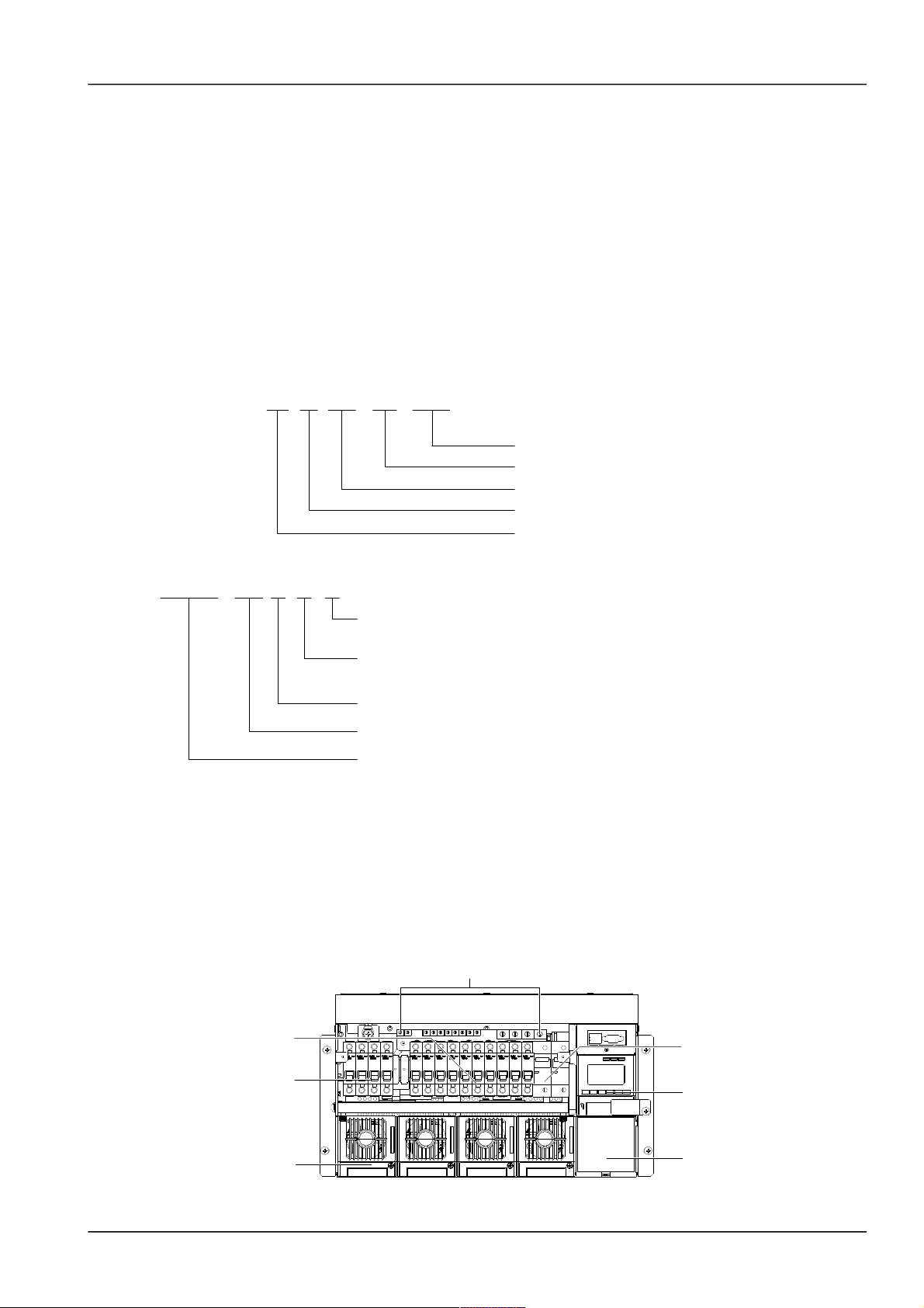
1.2 Composition And Configuration
System composition
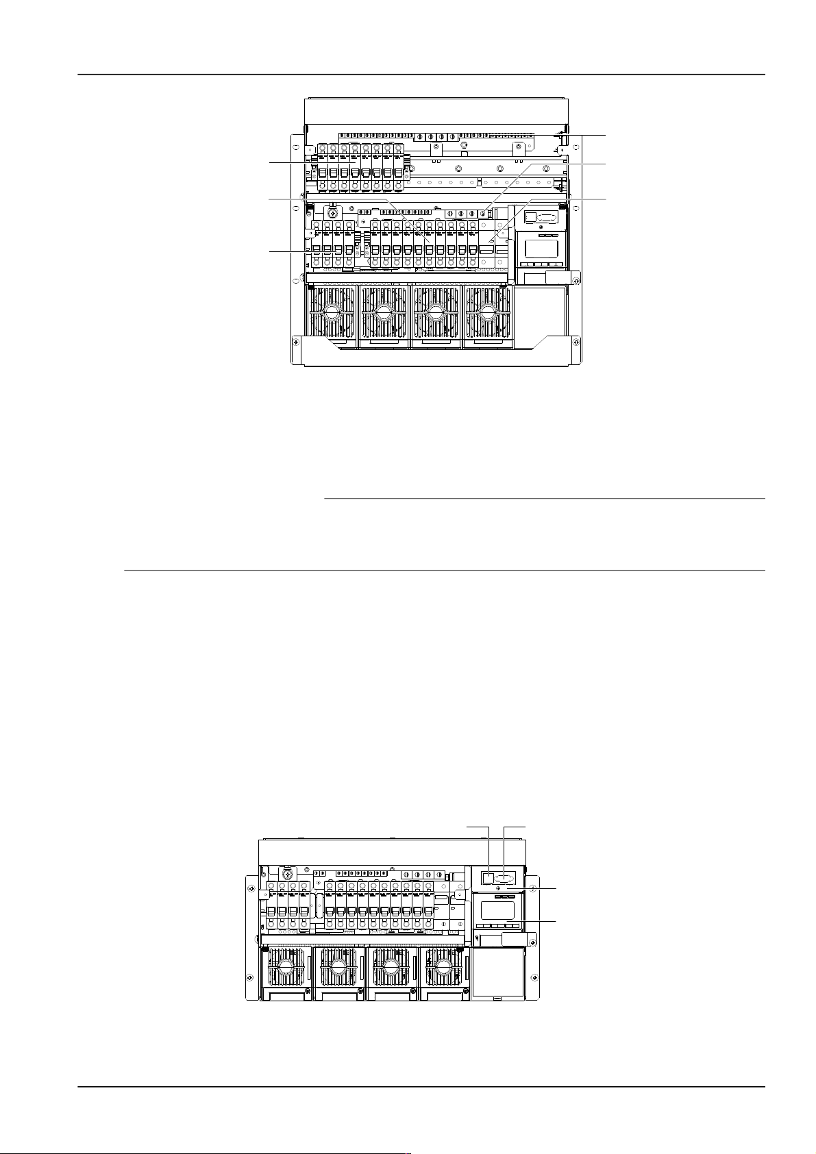
The system consists of power distribution parts, rectifiers and monitoring module. The rectifier model is R48-1800,
R48-2900U or R48-3200 and the model of the monitoring module is M501D or M500D. The internal structures of the
systems are shown in Figure 1-3 to Figure 1-6.
Rectifier
Battery MCB
Positive terminals
Monitoring module
Load MCB
AC input MCB
Dummy plate
Figure 1.1 NetSure 501 A50 system structure
NetSure 501 A50, NetSure 501 AA0, NetSure 701 A51 19-Inch Subrack Power Supply System User Manual
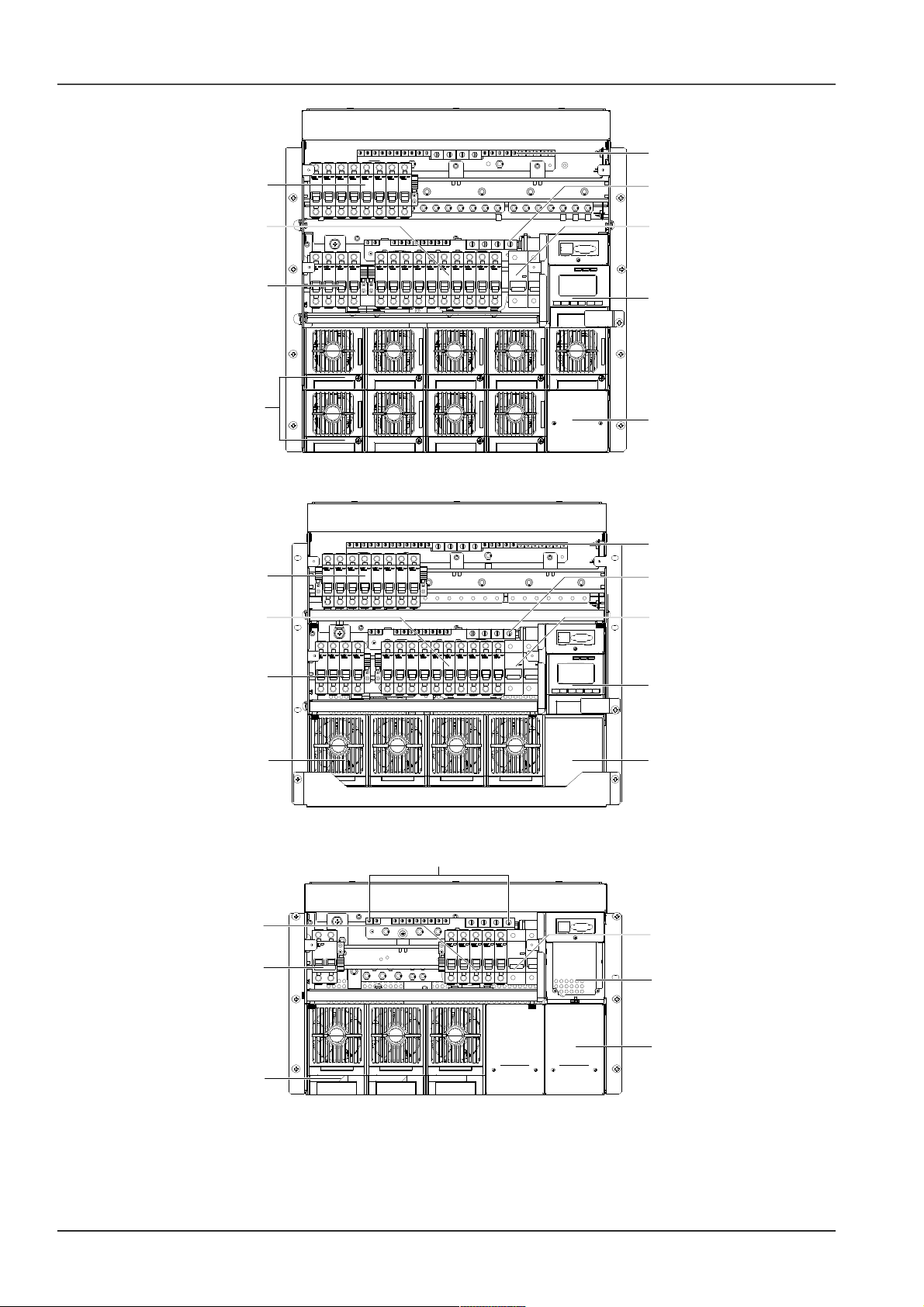
2 Chapter 1 Overview
Dummy plate
AC input MCB
Load MCB
Load MCB
Rectifier
Battery MCB
Monitoring module
Positive terminals
Positive terminals
Figure 1.2 NetSure 501 AA0 system structure
Dummy plate
AC input MCB
Load MCB
Load MCB
Rectifier
Battery MCB
Monitoring module
Positive terminals
Positive terminals
Figure 1.3 NetSure 701 A51 (PS48300-3A/3200) system structure
Battery MCB
Positive terminals
Monitoring module
Load MCB
AC input MCB
Dummy plate
Rectifier
Figure 1.4 NetSure 701 A51 (PS48300-3A/3200-X2) system structure
System configuration
The configurations of the power supply system are described in Table 1-1.
NetSure 501 A50, NetSure 501 AA0, NetSure 701 A51 19-Inch Subrack Power Supply System User Manual

Chapter 1 Overview 3
Table 1.2 Configuration of fixed- configuration system
Item NetSure 501 A50 NetSure 501 AA0
NetSure 701 A51
(PS48300-3A/3200)
NetSure 701 A51
(PS48300-3A/3200-X2)
Monitoring module Model: M501D Model: M501D Model: M501D Model: M500D
Rectifier
Model: R48-1800.
Standard configuration:
5 pieces
Model: R48-1800.
Standard configuration:
10 pieces
Model: R48-3200.
Standard configuration:
5 pieces
Model: R48-2900U.
Standard configuration: 3
pieces
AC power distribution 3P + N + PE/ 380Vac 3P + N + PE/ 380Vac 3P + N + PE/ 380Vac P + N + PE/ 230Vac
DC power distribution
BLVD load route: 3 ×
63A/1P, 3 × 32A/1P, 4 ×
10A/1P MCB
No LLVD load route
BLVD load route: 5 ×
63A/1P, 5 × 32A/1P, 8 ×
10A/1P MCB
No LLVD load route
BLVD load route: 5 ×
63A/1P, 5 × 32A/1P, 8 ×
10A/1P MCB
No LLVD load route
BLVD load route: 4 ×
40A/1P, 1 × 10A/1P MCB
No LLVD load route
Battery MCB 2 × 125A/1P 2 × 125A/1P 2 × 125A/1P 2 × 125A/1P
Maximum dimensions
483 (W) × 380 (D) × 267
(H)
483 (W) × 380 (D) × 490
(H)
483 (W) × 380 (D) × 445
(H)
483 (W) × 380 (D) × 311
(H)
Weight
25kg (not including
rectifiers and monitoring
module)
30kg (not including
rectifiers and monitoring
module)
25kg (not including
rectifiers and monitoring
module)
25kg (not including
rectifiers and monitoring
module)
Optional parts Temperature sensor and connected cables, remote monitoring unit, battery rack
1.3 Features
The rectifier uses the active Power Factor Compensation (PFC) technology, raising the power factor to 0.99
Wide AC input voltage range: 85V ~ 290V (NetSure 701 A51) or 85Vac ~ 300Vac (NetSure 501 A50 & NetSure
501 AA0)
The rectifier uses soft switching technology, raising the system efficiency to 89% (R48-1800)/ 90% (R48-3200)
Ultra-low radiation. With advanced EMC design, the rectifier meets international standards such as CE and
NEBS. Both the conducted and radiated interference reach Class B
The rectifier safety design complies with UL, CE and NEBS standards
High power density
Rectifiers are hot pluggable. It takes less than 1min to replace a rectifier
Two over-voltage protection methods are optional: hardware protection and software protection. The latter one
also has two optional modes: lock-out at the first over-voltage and lock-out at the second over-voltage
Perfect battery management: The management functions include the LLVD (optional), BLVD, temperature
compensation, auto voltage regulation, stepless current limiting, battery capacity calculation and on-line battery
test, etc
Up to 200 pieces of historical alarm records, and 10 sets of battery test data records
Network design: Providing multiple communication ports (such as RS232, modem, RJ45 and dry contacts),
which enables flexible networking and remote monitoring
Perfect lightning protection at AC side
Complete fault protection and fault alarm functions
NetSure 501 A50, NetSure 501 AA0, NetSure 701 A51 19-Inch Subrack Power Supply System User Manual

4 Chapter 2 Installation Instruction
Chapter 2 Installation Instruction
This chapter introduces installation and cable connection. Before installation, please read through safety regulations,
and then follow this instruction to carry out the installation step by step.
2.1 Safety Regulations
Certain components in this power system have hazardous voltage and current. Always follow the instructions below:
1. Only the adequately trained personnel with satisfactory knowledge of the power system can carry out the
installation. The most recent revision of these safety rules and local safety rules in force shall be adhered to during
the installation.
2. All external circuits that are below 48V and connected to the power system must comply with the requirements of
SELV as defined in IEC 60950.
3. Make sure that the power (mains and battery) to the system is cut off before any operations can be carried out
within the system subrack.
4. The power subracks shall be kept locked and placed in a locked room. The key keeper should be the one
responsible for the power system.
5. The wiring of the power distribution cables should be arranged carefully so that the cables are kept away from the
maintenance personnel.
2.2 Preparation
Unpacking inspection
The equipment should be unpacked and inspected after it arrives at the installation site. The inspection shall be done
by representatives of both the user and Emerson Network Power Co., Ltd.
To inspect the equipment, you should:
1. Open the packing case in which the packing list is put.
2. Take out the packing list.
3. Check against the packing label, including customer name, customer address, machine No., total amount, case
No., contract No.
Unpacking and inspection: After opening the packing case, check the goods one by one according to the goods list
on the packing label. The checking should include:
1. The number of the packing cases and the serial number marked on them.
2. The correctness of the equipment packing according to the packing list.
3. The number and model of the accessories according to the accessory list.
4. The completeness of the equipment set according to the system configuration.
5. The condition of the goods through visual inspection. For example, check the subrack for any damage and
condensation. Shake the rectifier module gently to see if any component or connection has loosened during
transportation.
Cables
The cable design should meet relevant industry standards.
It is recommended to use the RVVZ cables as AC cables. The cable should reach at least +70°C temperature
durability. With cable length shorter than 30 meters, the Cross-Sectional Area (CSA) calculation should be based on
the current density of 2.5A/mm2. The suggested CSA value is no less than 25mm2.
The CSA of DC cable depends on the current flowing through the cable and the allowable voltage drop. To select the
battery cable CSA, see Table 2-1. Select the DC load cable CSA according to the Table 2-2:
NetSure 501 A50, NetSure 501 AA0, NetSure 701 A51 19-Inch Subrack Power Supply System User Manual
Chapter 2 Installation Instruction 5
Table 1.1 Battery cable CSA selection
Battery MCB rated current Max. battery current Min. cable CSA Max. cable length (allowable voltage drop: 0.5V)
125A 100A 25mm
2
14m
Note:
1. The specs are applicable at ambient temperature of 25°C. If the temperature is higher or lower than this, the CSA of the cable
should be increased.
2. The battery cable should reach at least +90°C heat durability. It is recommended to use double-insulated copper-core flame
retardant cable as battery cable
Table 1.2 DC load cable selection
Load route rated
current
Max. output
current
Min. cable
CSA
Max. cable length (volt drop:
0.5V, with min. CSA)
Max. cable CSA
Max. cable length (volt drop:
0.5V, with max. CSA)
63A 32A 16mm
2
7m 25mm
2
11m
32A 16A 16mm
2
14m 25mm
2
22m
10A 5A 6mm
2
17m 25mm
2
71m
Note:
The specs are applicable at ambient temperature of 25°C. If the temperature is higher or lower than this, the CSA of the cable
should be increased
The MCB capacity should be strictly limited so that it can function properly upon load over-current. The
recommended MCB capacity is 1.5 ~ 2 times larger than the load peak capacity.
The CSA of the system earth cable should be consistent with that of the maximum power distribution cable and no
less than 35mm2.
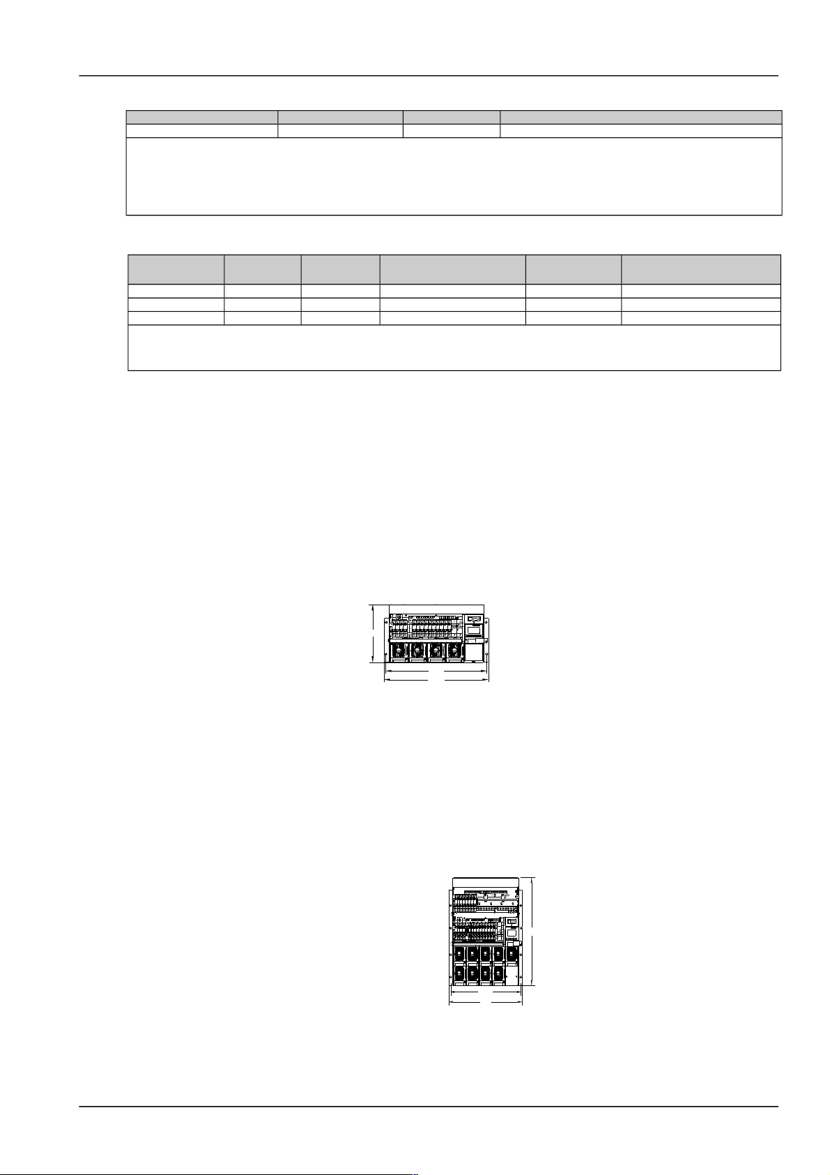
2.3 Mechanical Installation
For the convenience of maintenance, users should maintain a clearance of 800mm at the front of the power supply
system.
Insert the power supply system into the cabinet. Install the screws in the four installation holes as shown in Figure 2-1
to Figure 2-4 with a Phillips screwdriver.
466
483
266
Figure 1.1 Installation size of NetSure 501 A50 (unit: mm)
490
483
466.8
Figure 1.2 Installation size of NetSure 501 AA0 (unit: mm)
NetSure 501 A50, NetSure 501 AA0, NetSure 701 A51 19-Inch Subrack Power Supply System User Manual
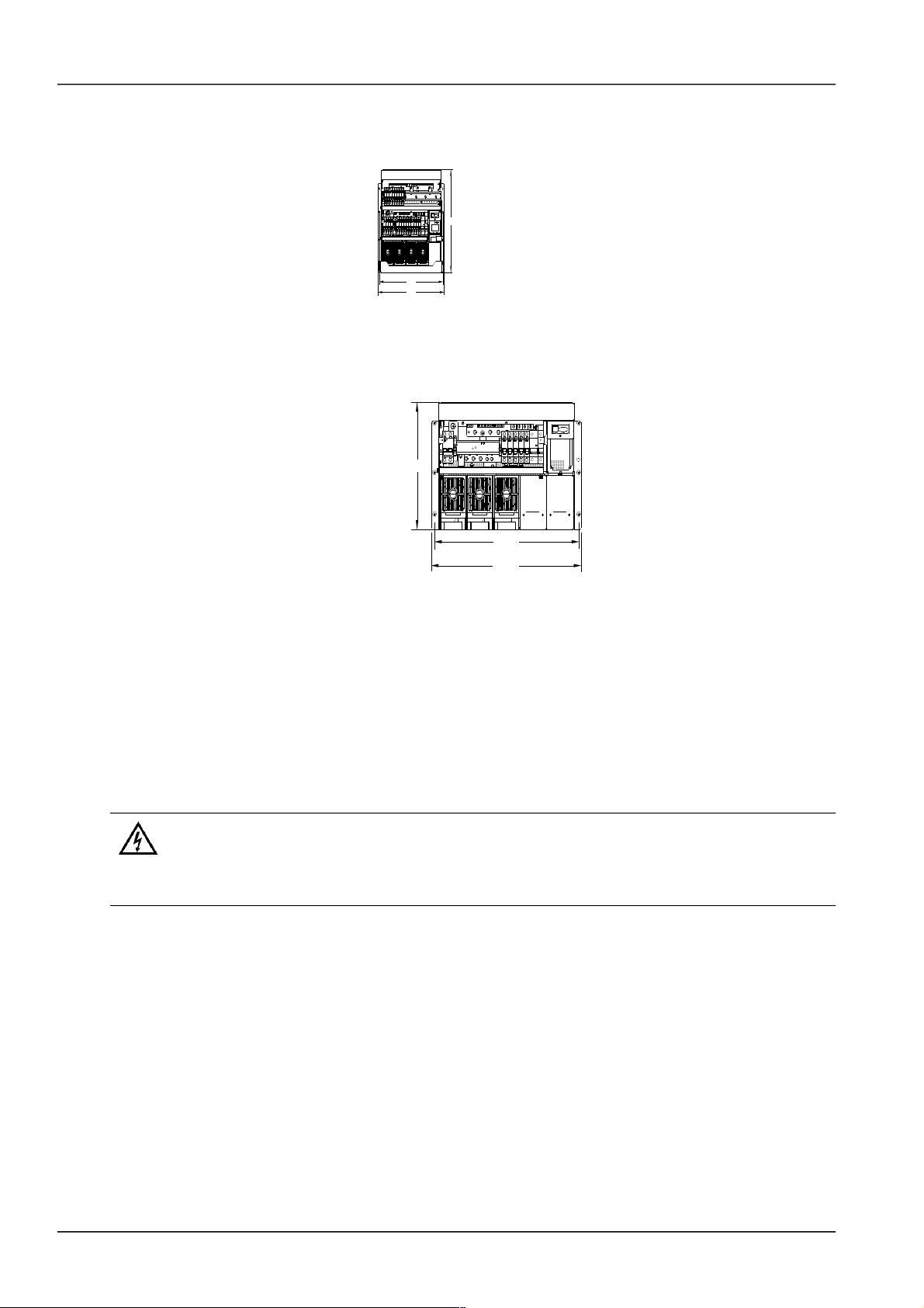
6 Chapter 2 Installation Instruction
483
466
445
Figure 1.3 Installation size of NetSure 701 A51 (PS48300-3A/3200) (unit: mm)
465.5
483.0
311
Figure 1.4 Installation size of NetSure 701 A51 (PS48300-3A/3200-X2) (unit: mm)
2.4 Electrical Installation
2.4.1 Connecting Power Cables
Connecting AC input cables
1. Switch off all MCBs before the electrical connection.
2. Only the qualified personnel can do the mains cable connection.
Feed all the cables into the subrack from top of the subrack. Take the NetSure 701 A51 power supply system as an
example, the position of the connection terminals are shown in Figure 2-5. Connect the AC input cables to the AC
input MCB.
NetSure 501 A50, NetSure 501 AA0, NetSure 701 A51 19-Inch Subrack Power Supply System User Manual
Chapter 2 Installation Instruction 7
AC input MCB
Load MCB
Load MCB
Battery MCB
Positive terminals
Positive terminals
Figure 1.1 MCB and terminal positions
Connecting load cables
Connect the negative cable of the load to the upper terminal of load MCB. Connect the positive cable of the load to
the DC positive busbar. The terminals are as shown in Figure 2-5.
Connecting battery cables
1. Note
1. The batteries may have dangerous current. Before connecting the battery cables, the corresponding battery input MCBs or the
battery cell connector must be disconnected to avoid live state of the power system after installation.
2. Be careful not to reverse connect the battery. Otherwise, both the battery and the power system will be damaged!
1. Connect one end of the negative battery cable to the upper terminal of battery MCBs. Connect one end of the
positive battery cable to the DC positive bus bar.
2. Connect copper lugs to the other end of the battery cables. Bind the connecting parts with insulating tape, and put
them beside the battery. Connect the cables to the battery when the DC distribution unit is to be tested.
2.4.2 Connecting Signal Cables
S6415X2 user connector board cable connection
Take the NetSure 501 A50 power supply system as an example, the position of the user connector board is shown in
Figure 2-6. Two communication interfaces are located in the panel: Ethernet and RS232 interface. The power supply
system can be connected to Ethernet through the Ethernet interface or connected to modem through RS232
interface.
Monitoring module
Network port
RS232 interface
S6415X2 user
connector board
Figure 1.1 User connector board position
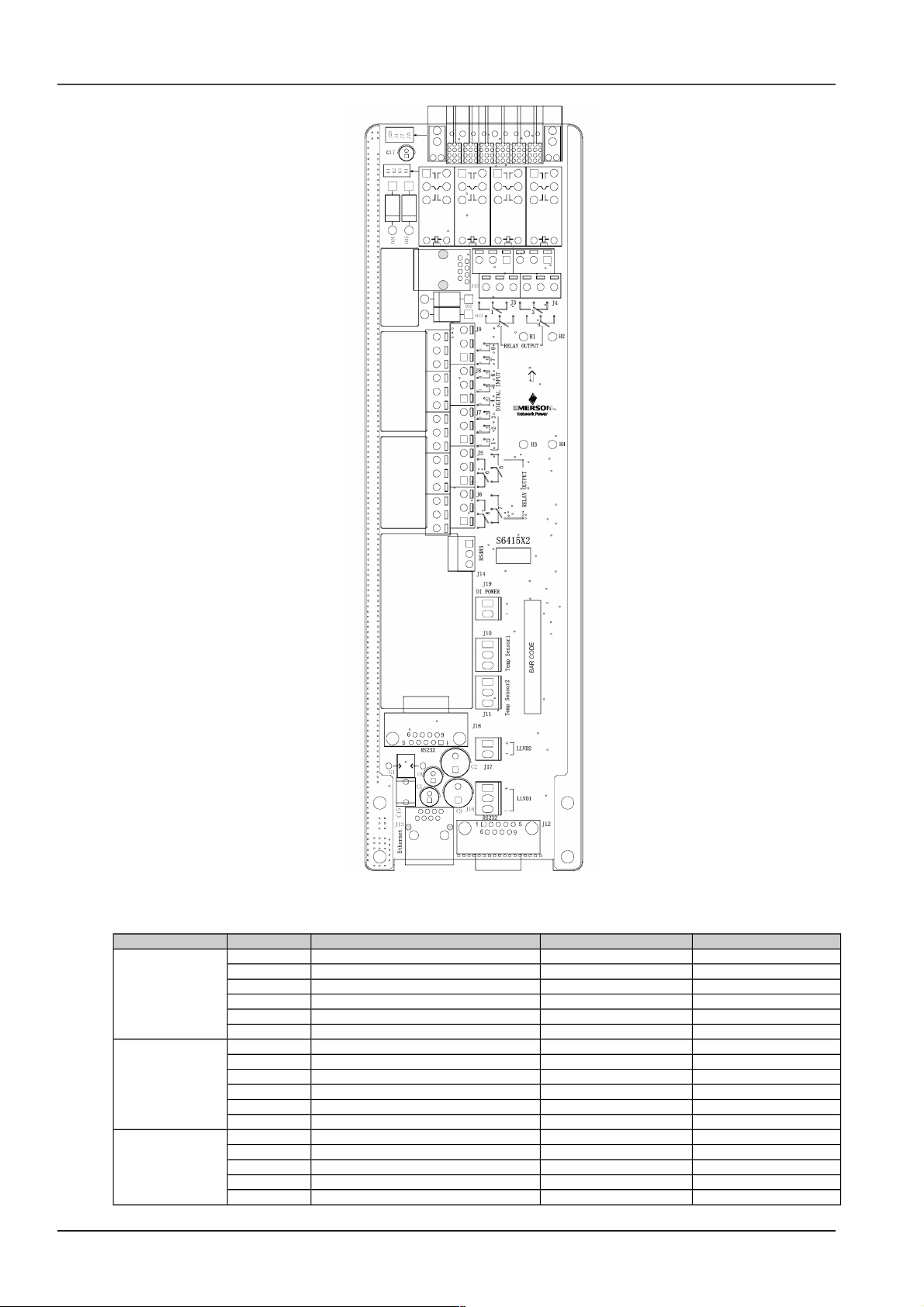
The interfaces of the signal transfer board are shown in Figure 2-7. The functions of the interfaces are shown in Table
2-3.
NetSure 501 A50, NetSure 501 AA0, NetSure 701 A51 19-Inch Subrack Power Supply System User Manual
8 Chapter 2 Installation Instruction
Figure 1.2 S6415X2 interface
Table 1.2 Interface functions
Connector Pin Signal name Mark number Logic relation
J3
1 Relay output 1 normal close DO1_NC
2 Relay output 2 normal close DO2_NC
3 Relay output 1 common DO1_COM
4 Relay output 2 common DO2_COM
5 Relay output 1 normal open DO1_NO
6 Relay output 2 normal open DO2_NO
J4
1 Relay output 3 normal close DO3_NC
2 Relay output 4 normal close DO4_NC
3 Relay output 3 common DO3_COM
4 Relay output 4 common DO4_COM
5 Relay output 3 normal open DO3_NO
6 Relay output 4 normal open DO4_NO
J5 1 Relay output 5 normal close DO5_NC
2 Relay output 6 normal close DO6_NC
3 Relay output 5 common DO5_COM
4 Relay output 6 common DO6_COM
5 Relay output 5 normal open DO5_NO
NetSure 501 A50, NetSure 501 AA0, NetSure 701 A51 19-Inch Subrack Power Supply System User Manual

Chapter 2 Installation Instruction 9
Connector Pin Signal name Mark number Logic relation
6 Relay output 6 normal open DO6_NO
J6
1 Relay output 7 normal close DO7_NC
2 Relay output 8 normal close DO8_NC
3 Relay output 7 common DO7_COM
4 Relay output 8 common DO8_COM
5 Relay output 7 normal open DO7_NO
6 Relay output 8 normal open DO8_NO
J10
1 Digital circuits power +5V
2 Temperature signal 1 input TEMP1 4~20mA
3 Analog ground GND
J11
1 Digital circuits power +5V
2 Temperature signal 2 input TEMP2 4~20mA
3 Analog ground GND
J12, J18
1 Data Carrier Detect DCD232
2 Receive Data RXD232
3 Transmit Data TXD232
4 Data Terminal Ready DTR232
5 Data Communication ground DGND
6 Empty
7 Request To Send RTS232
8,9 Empty
J13
1 Ethernet TX+ NETTX+
2 Ethernet TX- NETTX3 Ethernet TR+ NETTR+
4 Empty
5 Empty
6 Ethernet TR- NETTR-
7~12 Empty
J14
1 RS485 communication+ E485+
2 RS485 communication- E4853 Protection ground PGNG
J19
1 48V+ POWER+
2 48V- POWER-
Modem cable connection
Modem is an optional accessory, suitable for those who have purchased the modem remote monitoring system.
Modem configuration:
In modem mode, "Y" should be selected for the communication parameter "MODEM" of the monitoring module. If
modem has the Automatic Answer indicator (AA), the indicator will turn on once modem and monitoring module are
powered on. In the modem mode, the monitoring module will initialize modem upon power-on, reset or upon
communication interruptions that last more than one hour.
NetSure 501 A50, NetSure 501 AA0, NetSure 701 A51 19-Inch Subrack Power Supply System User Manual

10 Chapter 3 Installation Testing
Chapter 3 Installation Testing
This chapter introduces procedures of installation testing. The corresponding safety rules shall be adhered to in the
test.
3.1 Installation Check And Startup
Before the test, inform the chief manufacturer representative. Only trained electrical engineer can maintain and
operate this equipment. In operation, the installation personnel are not allowed to wear conductive objects such as
watches, bracelets, bangles and rings.
During operation, parts of this equipment carry hazardous voltage. Misoperation can result in severe or fatal injuries
and property damage. Before the test, check the equipment to ensure the proper earthing. Installation check must be
done before testing. Then the batteries can be charged for the first time.
Make sure that the AC input MCBs, battery MCBs and load MCBs are switched off. Make sure that all the devices are
properly installed.
Installation check
OK Comments
Check all the MCBs and cables. Are their models correct?
Check the bus bar connections, input and output cable connection, and connection between the power
system and the system grounding.
Check the if the number and connections of the batteris are correct. Check the polarity of the battery string
with a voltmeter.
Make sure all the cable connections are firm and reliable.
Startup preparations
OK Comments
Make sure that all the MCB are switched off.
Measure the AC input voltage. Make sure the input voltage is within the allowable range.
Umin=___V
Check that the communication and alarm cables are connected to the signal transfer board.
Check that the temperature sensor, if any, has been installed.
Check that the battery string circuit is not closed.
Connect the disconnected batteries to the battery string circuit
Measure with a voltmeter across the connection points of each battery and make sure that the polarity is
right. For a lead-acid battery with 24 cells, the voltmeter should read 2.0-2.1V/cell or 48-51V/battery. If the
voltage of certain cell is lower than 2.0V, that cell must be replaced.
Umin=___V
Check with an ohmmeter that there is no short circuit between the positive & negative distribution bus
bars, or between the positive & negative battery poles
(Note: Pull out all modules before the check and restore them after the check)
Startup
OK Comments
Switch on the system AC input MCB. The green LED on the rectifier will be on and the fan will start running
after a certain delay. The monitoring module will show that the power supply voltage is 53.5V.
Check the system voltage and busbar polarity with a voltmeter. The voltage difference between the
measured value and displayed value should be less than 0.2V.
Start and stop each rectifier of the system by unplugging and inserting each rectifier. Check their output
voltages.
3.2 Basic Settings
When the system is put into service for the first time, the parameters of monitoring module must be set based on the
actual system configuration, such as battery number, capacity, user’s charge current limit and other functional
requirements. Only after that can the monitoring module display system operation information and control the output.
For monitoring module parameter setting method, see 4.7Setting System Parameters if using M500D.
5.2.5Parameter Set if using M800D. See 5.7 Setting System Parameters if using M501D.
NetSure 501 A50, NetSure 501 AA0, NetSure 701 A51 19-Inch Subrack Power Supply System User Manual

Chapter 3 Installation Testing 11
OK Comments
The system model has been set correctly in factory before delivery, check that the setting agrees with
the actual system (NetSure 501 A50: 48V/30A/SET/NONE; NetSure 701 A51 (PS48300-3A/3200):
48V/50A/300/ NONE; NetSure 701 A51 (PS48300-3A/3200-X2): 48V/50A/SET/NONE; NetSure 501
AA0: 48V/30A/300/NONE).
The battery string number set at the monitoring module should be the same as the number actually
connected. (By default: 2)
Set the battery capacity according to the actual capacity of the battery connected to the system.
Default: 300Ah.
Configure the temperature coefficient according to the battery manufacturer’s requirement. Setting
range: 0-500mV/°C. By default: 72mV/°C. (if no temperature sensor is installed, do not set this
parameter)
Set the charge current limit according to your needs. Setting range: 0.1~0.25C10. (By default: 0.1C10)
Set the monitoring module according to the voltage suggested by the battery supplier.
Floating Charge (FC) voltage range: 42V ~ Boost Charge (BC) voltage. Default: 53.5V.
BC voltage range: FC voltage ~ 58V. By default: 56.4V.
For batteries that do not need BC, set the BC voltage to FC voltage plus 0.1V.
Put through the battery MCBs and connect the batteries.
3.3 Alarm Check And System Operation Status Check
Alarm check
Check that all functional units can trigger alarms that can be displayed on the monitoring module.
OK Comments
Pull out one rectifier. The “Rect N Com Failure” alarm should be triggered. Insert the rectifier in. The
alarm should disappear. Repeat the same procedures on other rectifiers.
Remove battery MCB 1. The “Batt1 Failure” alarm should be triggered. Put on the MCB. The alarm
should be cleared. Repeat the same on battery MCB 2.
Switch off a load MCB connected to a load route. The alarm “Load N Failure” should be triggered.
Switch on the MCB, and the alarm should be cleared. Repeat the same on the other load MCBs.
Remove all the battery input MCBs. Keep only one rectifier in operation. Through the monitoring
module, adjust the rectifier FC voltage to make it lower than the alarm point. The alarm “DC Voltage
Low” should be triggered.
Keep the rectifiers in operation. Set through the monitoring module the battery management
parameter to “Manual”. Enter the maintenance menu at the monitoring module. Select “Disconnect”
and confirm it. The battery protection contactor should be open, and the “BLVD” alarm should be
displayed at the monitoring module.
Note: when the preceding alarms are generated, the monitoring module will give alarms after approximately 3s. Refer to
4.5Querying Alarms And Setting Alarm Plans, 5.2.3Running Information or 6.5Querying And Handling Alarms for methods of
querying alarms.
System operation status check
There should be no alarms during normal system operation. The system operation status check can be conducted
through the monitoring module.
For the parameter query method, refer to 4.3Querying System Status if using M500D. 5.2.3Running Information if
using M800D. Refer to 6.3 Querying System Status and 6.4 Querying Rectifier Status if using M501D.
OK Comments
The system model is NetSure 501 A50: 48V/30A/SET/NONE; NetSure 701 A51 (PS48300-3A/3200):
48V/50A/300/ NONE; NetSure 701 A51 (PS48300-3A/3200-X2): 48V/50A/SET/NONE; NetSure 501
AA0: 48V/30A/300/NONE
The monitoring module should display the correct AC voltage.
The monitoring module should be able to display the DC voltage. The difference between the
displayed voltage and that measured at the bus bar should be less than 1%.
The monitoring module should display the battery current. The difference between the displayed and
measured battery current should be less than 1%.
Check the number of the rectifier through the monitoring module. The number should be consistent
with the actual number.
NetSure 501 A50, NetSure 501 AA0, NetSure 701 A51 19-Inch Subrack Power Supply System User Manual

12 Chapter 3 Installation Testing
OK Comments
Check the voltage, current, current limiting point of rectifiers through the monitoring module. They
should agree with the actual parameters.
For the system configured with temperature sensor, the monitoring module should be able to display
the battery ambient temperature. Hold the probe of the temperature sensor with hand and watch the
monitoring module, which should diplay the change of temperature.
3.4 Final Steps
OK Comments
Disconnect all test equipment from the system and make sure that materials irrelevant to the equipment
have been all removed.
Restore the equipment to its original condition and close the cabinet door.
Check and handover the equipment that the user has purchased.
Note down all the operations taken, including time of the operation and name of the operator.
If any defect is found in this equipment, inform the personnel responsible for the contract.
If repairing is needed, please fill in the FAILURE REPORT and send the report together with the defective unit to the
repairing center for fault analysis.
NetSure 501 A50, NetSure 501 AA0, NetSure 701 A51 19-Inch Subrack Power Supply System User Manual

Chapter 4 Use Of Monitoring Module M500D 13
Chapter 4 Use Of Monitoring Module M500D
This chapter introduces the front panel and functional keys briefly, and expounds screen contents, access method,
system controlling, information querying and parameter setting.
After the monitoring module is powered on, the language selection screen will pop up, and the monitoring module is
initialized. The default language is Chinese. After the initialization, the first system information page will appear.
4.1 Front Panel
There are backlit LCD display, functional keypad, indicators and positioning pin on the front panel of M500D
monitoring module, as shown in the following figure:
Alarm indicator
Run indicator
Critical alarm indicator
LCD
Functional keys
Handle
ESC
M500D
ENT
Figure 1.1 Front panel of M500D monitoring module
Description of the indicators on the front panel is in the following table:
Table 1.2 Monitoring module indicator description
Indicator Normal state Fault state Fault cause
Run (green) On Off No operation power supply
Alarm (yellow) Off On There are observation alarms
Critical alarm (red) Off On There are major or critical alarm
M500D monitoring module uses a 128 × 64 LCD, a keypad with 6 keys. The interface language is Chinese/English
optional.
Table 1.3 Description of monitoring module keypad
Key Function
ESC Return to the upper level menu
ENT Enter the main menu or confirm the menu operation
“▲” and “▼” Shift among parallel menus. For a character string, these 2 keys can be used to shift among different options
““ and ““ Change values at a value setting interface. For a character string, these 2 keys can move the cursor left or right
4.2 Power On Order
After the system is powered on for the first time, you should set the system type according to the actual configuration.
The monitoring module will restart after the system type is changed. In that case, you should re-configure those
parameters whose default values are inconsistent with the actual situation. Only after that can the monitoring module
operate normally.
After configuring the system parameters, you can carry out various operations directly without resetting the parameter
values. As for those important parameters related to battery management, such as BLVD, you should be fully aware
of their influence upon the system before you change their values.
NetSure 501 A50, NetSure 501 AA0, NetSure 701 A51 19-Inch Subrack Power Supply System User Manual

14 Chapter 4 Use Of Monitoring Module M500D
2. Note
For the exact meanings of the abbreviations used in LCD displayer, see Appendix 7 Glossary.
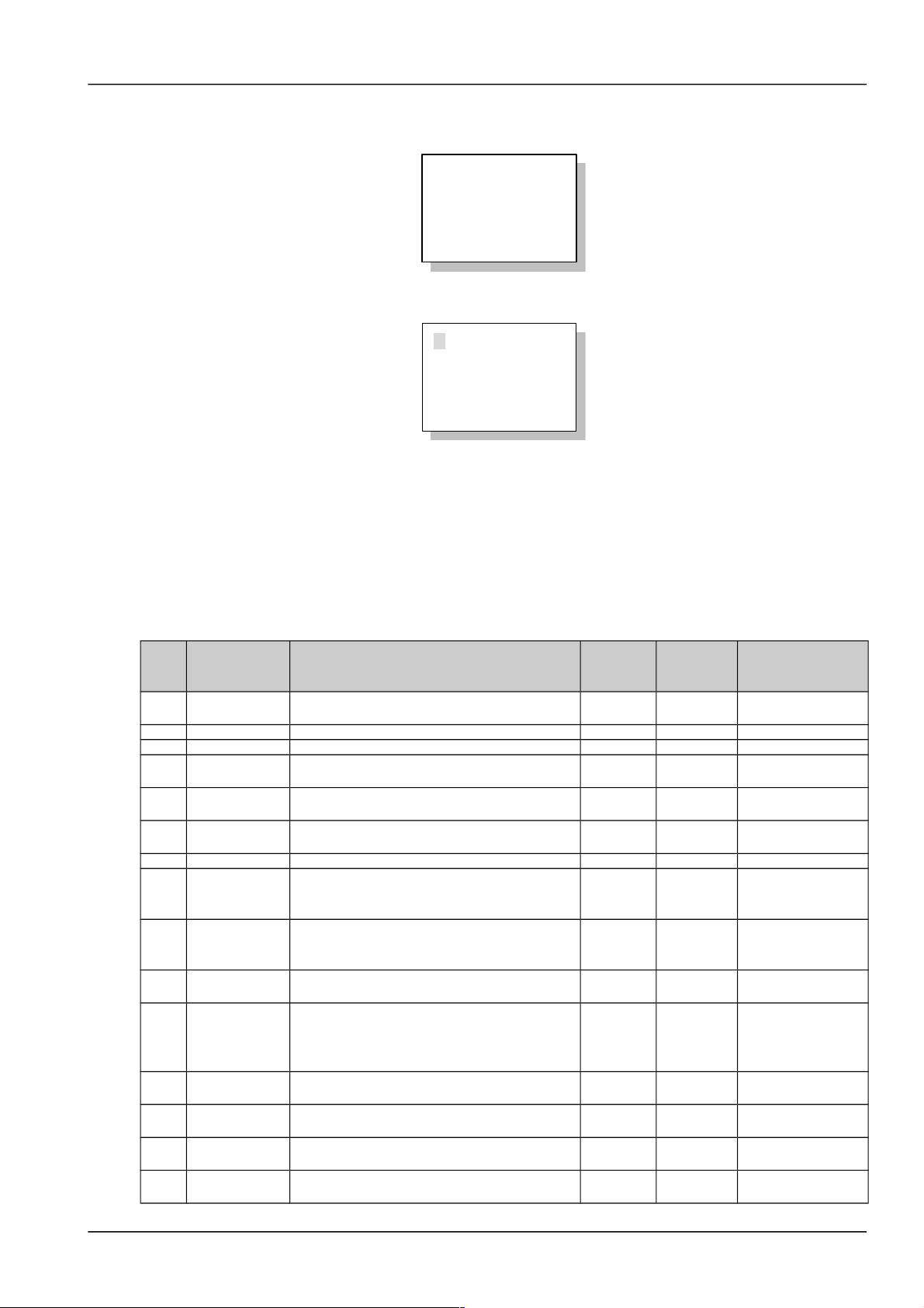
1. The LCD will prompt you to select a language once the monitoring module is powered on.
English
English
▼
You can use “◄”, “►”, “▲” or “▼” to select the language you want, and press “ENT” to confirm.
2. The monitoring module will prompt you to wait, and start initialization.
Waiting…
▼
3. The first system information page appears
2004-5-12
53.5V 125A
System:No Alarm
Auto /BC
▼
The system information is shown in many pages. You can repeatedly press “▼” to view other system information
pages in a cycle.
4. At any system information page, press “ESC” to enter the help page, which displays software version (SW),
product code (PC), product reversion (PR) and serial number (SS).
SW: V1.20
PC: 1M502D
PR: A00
SS: 01051200012
5. At any system information page, press “ENT” to enter the “MAIN MENU” page, which contains 3 sub-menus:
“Status”, “Maintenance” and “Settings”.
MAINMENU
Status
Maintenance
Settings
You can press “▲” or “▼” repeatedly to select a sub-menu, and press “ENT” to enter the sub-menu. Press “ESC” to
return to the menu of higher level.
1) Status
Including rectifier information, active alarm information and alarm history information.
2) Maintenance
The maintenance operation can be conducted only when the battery management mode is set to “Manual”. The
maintenance includes battery FC, BC and test, load power off/on, battery power off/on and rectifier voltage trimming,
current limit, switch control and resetting.
NetSure 501 A50, NetSure 501 AA0, NetSure 701 A51 19-Inch Subrack Power Supply System User Manual

Chapter 4 Use Of Monitoring Module M500D 15
3) Settings
Including the setting of alarm parameter, battery parameter, AC/DC parameter, rectifier parameter and system
parameter.
4.3 Querying System Status
4.3.1 First Page Of System Information
1. At the main menu page, press “ESC” to return to the first system information page.
2. If no operation is conducted on the monitoring module keypad for 8 minutes, the LCD will return to the first system
information page and shut down the back light to protect the screen. Pressing any key will turn on the back light.
The first system information page contains the major system operation information, including date/time, busbar
voltage, total load current, system operation state (normal or alarm), battery management mode (AUTO or MANUAL)
and battery state.
Among which, the battery state include FC, temperature compensation, BC, Cyclic Boost, test, short test and
scheduled test. The current time are displayed in two pages shifting at the interval of 2s. One page shows year,
month and date, the other shows hour, minute and second. The year is displayed with four digits; other time units are
in two digits.
2004-5-12
53.5V 125A
System:No Alarm
Auto /BC
▼
Or
12:20:30
53.5V 125A
System: No Alarm
Auto /BC
▼
3. Note
1. At this page, you may use “◄” and “►" to adjust the LCD contrast (7-level).
2. If there has been no keypad operation for 8 minutes, the monitoring module will return to the first system information page.
The time of that return will be recorded automatically, and can be queried through the host.
4.3.2 Other System Information Pages
The system information is shown in many pages. The default page of the monitoring module after the system power
on is the system information first page. You can press “▲” or “▼” to scroll up or down to view more operation
information, as shown in the following page:
Battery information page
Batt1: 50A
Remain : 60%
Batt2: 50A
Remain: 60%
▼
1. Battery 1, battery 2
They represent respectively the current of the battery that battery shunt 1 and shunt 2 is connected to. If the “Shunt
Coeff” of a certain battery group is set to “No”, this situation will be reflected at the battery information page by “Not
connected”, and no actual capacity will be displayed.
2. Actual battery capacity
The monitoring module can approximately calculate the remaining battery capacity in real time. Through configuration
at the host, the remaining battery capacity can be displayed in the mode of percentage, remaining Ah or remaining
time, etc. The default is the percentage.
NetSure 501 A50, NetSure 501 AA0, NetSure 701 A51 19-Inch Subrack Power Supply System User Manual

16 Chapter 4 Use Of Monitoring Module M500D
During the normal BC/FC management, the monitoring module regards the rated capacity as the capacity that each
battery group can reach. When the battery discharges, the monitoring module will calculate the battery remaining
capacity according to the discharge current, discharge time and the preset “battery discharge curve”. When the
battery is being charged, the monitoring module will calculate the real-time battery capacity according to the detected
charge current, charge time and preset “battery charge efficiency”. If the calculated battery remaining capacity is
higher than the rated capacity, the monitoring module will automatically change the calculated battery remaining
capacity to the rated capacity.
AC information page
1. If the power system is a 3-phase input system with manual-switchover between 2 AC inputs, the voltage of the
three phases will be displayed.
AC
Phase A: 221V
Phase B: 225V
Phase C: 223V
▼
2. If the power system is a 1-phase input system with manual-switchover between 2 AC inputs, the single-phase
voltage will be displayed.
AC
Single: 221V
▼
3. If there is no AC sampling board in the power system, the LCD will display the max and min AC input voltages of all
rectifiers.
Rect AC Volt
Max: 230V
Min: 220V
▼
BC prompt and temperature information page
System Power:
23%
Cyc BC After:
55h
▼
Bat . Temp
:
25
°C
Amb.Temp
:
5
°C
▼
If the monitoring module bans BC and no temperature sensor is configured, this page will not be displayed.
The first line of the information page displays the BC prompts, which will be different with different systems, including:
1. Prompt the time of next Cyclic Boost according to the battery state
2. If BC is going on, the “Charging” will be prompted
3. If BC is disabled, this row will be empty
The 2nd and 3rd rows of the page are the temperature information detected by the temperature sensor. The display will
vary with different parameter settings (see 4.7 for parameter setting). If the temperature sensor is not connected or is
faulty, system will prompt invalid. Meanwhile, the 4th row will display “Check Temp Sensor”.
NetSure 501 A50, NetSure 501 AA0, NetSure 701 A51 19-Inch Subrack Power Supply System User Manual

Chapter 4 Use Of Monitoring Module M500D 17
4.4 Querying Rectifier Status
The rectifier information includes the rectifier serial No., voltage, current, current limit, mains situation, rectifier power
limit and temperature power limit.
1. At any page of the system information, press “ENT” to enter the main menu.
2. Use “▲” or “▼” keys to select the “Status” sub-menu in the main menu, and press “ENT” to confirm.
STATUS
Rectifiers
Active Alarm
Alarm History
3. Use “▲” or “▼” to select the “Rectifiers” submenu, as shown in the above figure. Press “ENT” to confirm.
Rectifier 1:
▲
53.5V 12.3A
Inp On Out On
AC Volt: 220V ▼
Rectifier 1:
▲
Power Used:
63%
Temp. Derated: Y
▼
SW: V1.20
▲
PC: 1RS4800
PR: A00
SS: 01051200012▼
The information of every rectifier is displayed in three pages. The information in the first page includes: output voltage
and current, input/ output on/off state and AC input voltage. The information in the second page includes: the states
of “Power Used” (the percentage of actual output power in rated output power) and “Temp Derated”. The information
in the third page includes: software version (SW), product code (PC), product reversion (PR) and serial number (SS).
Press “►” to scroll to the next page, or “◄” to return to the last.
4. Press “▼” or “▲” to query other rectifier’s information.
At most 48 pieces of rectifier’s information can be displayed. If the rectifier does not exist, there will be no information.
If the rectifier communication is interrupted, the information will be displayed in high light.
5. At any rectifier information page, press “ESC” repeatedly and you can return to the higher-level menus.
4.5 Querying Alarms And Setting Alarm Plans
The monitoring module can locate and record the system fault according to the collected data, as well as raise
audible/visual alarms and output through dry contact according to the preset alarm level. Meanwhile, it reports the
alarms to the host.
You can query historical alarms and active alarms through the LCD of the monitoring module.
4.5.1 Querying Active Alarm
When a new alarm is raised, and there is no operation on monitoring module keypad within 2 minutes, the LCD of the
monitoring module will prompt automatically the active alarm.
If there are multiple alarms in the current system, you can query alarms through the following steps:
1. At any system information page, press “ENT” to enter the main menu
2. Use “▲” or “▼” to select the “Status” submenu in the main menu and press “ENT” to confirm.
STATUS
Rectifiers
Active Alarm
Alarm History
NetSure 501 A50, NetSure 501 AA0, NetSure 701 A51 19-Inch Subrack Power Supply System User Manual

18 Chapter 4 Use Of Monitoring Module M500D
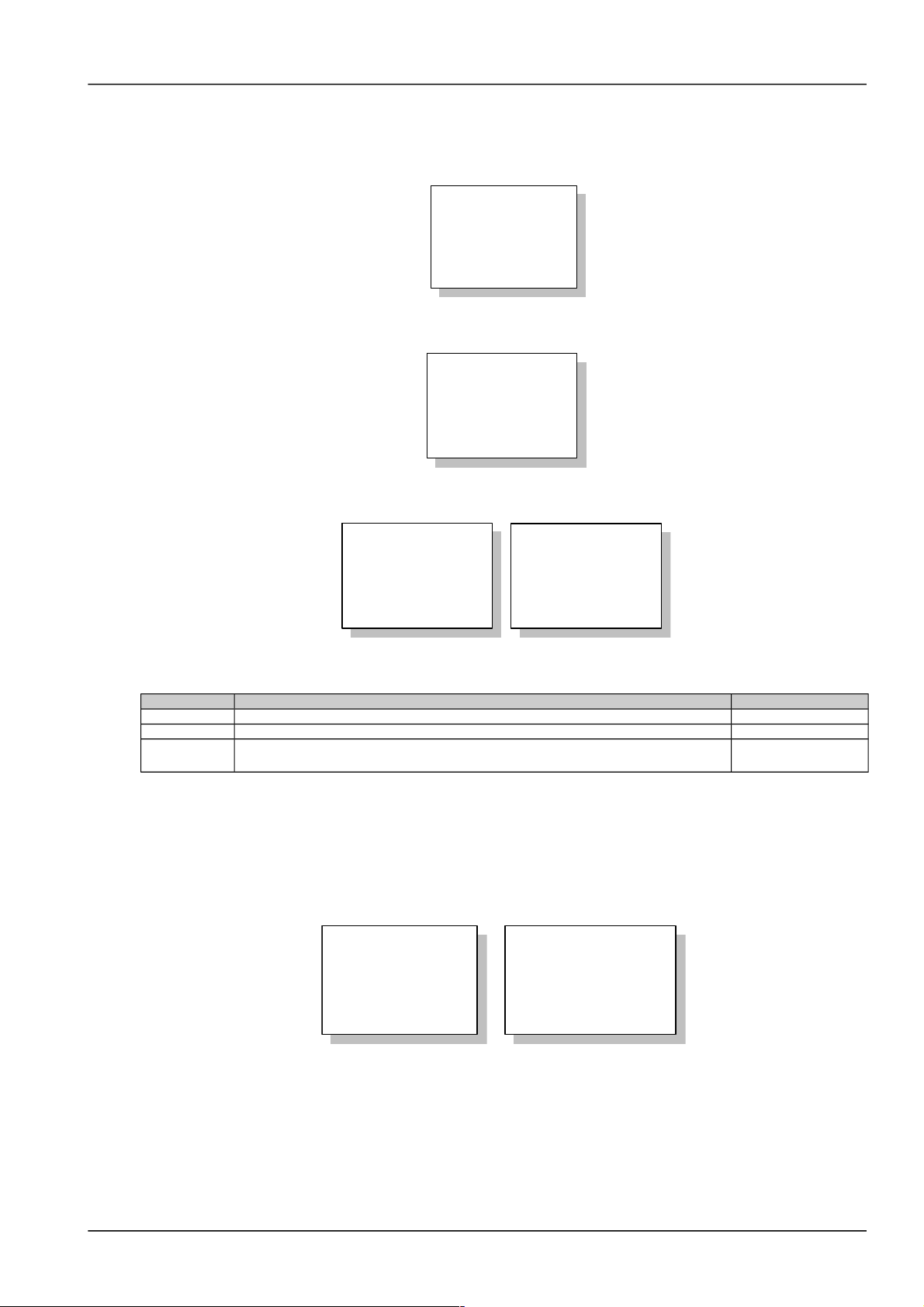
3. Press “▲” or “▼” to select the “Active Alarm”, as shown in the above figure, and press “ENT” to confirm.
1) If there is no active alarm, “Active Alarm: None” will be displayed
ACTIVE ALARM
None
2) If there is any alarm, the display will be like the following:
ACTIVE ALARM
3
1 Major Alarm
AC1 Ph-A Failure
040412 12:30:23
The information in the active alarm information pages includes: alarm serial No., alarm level, alarm name and time
(year, month, day, hour, minute and second). The alarm raising time determines the sequence it is displayed, with the
latest alarm displayed first. Use “▲” or “▼” to view all active alarms.
While querying rectifier alarms, press “►”, and the rectifier ID will be displayed, and the “Run” indicator of the
corresponding rectifier will blink.
Rect ID
01051200012
In the case of battery test alarm or maintenance time alarm, press “►” to display the prompt information.
Notice:
Press ENT Clear,
ESC Key Quit.
In the prompt page, press “ENT” to confirm the alarm.
4. At any active alarm information page, press “ESC” repeatedly and you can return to the higher-level menus.
4.5.2 Querying Alarm History
1. At any system information page, press “ENT” to enter the main menu
2. Press “▲” or “▼” to select the “Status” submenu, and press “ENT” to confirm.
STATUS
Rectifiers
Active Alarm
Alarm History
NetSure 501 A50, NetSure 501 AA0, NetSure 701 A51 19-Inch Subrack Power Supply System User Manual
Chapter 4 Use Of Monitoring Module M500D 19
3. Use “▲” or “▼” to select the “Alarm History”, as shown in the above figure and press “ENT” to confirm.
If there is no historical alarm, the prompt will be “Alarm History: None”.
ALARM HISTORY
None
The historical alarms of the monitoring module are stored in cyclic order. Up to 200 alarms will be recorded. Above
that, the earliest alarm will be cleared automatically.
1 Alarm
SPD
Fault
040411 20:08:30
040411 22:08:30
At the monitoring module, the displayed historical alarm information includes: alarm serial No., alarm name and alarm
start/end time (year, month, day, hour, minute, second).
If it is a rectifier that raised the alarm, the ID of that rectifier will be displayed.
4. At any Alarm History information page, press “ESC” repeatedly to return to the higher-level menus.
4.5.3 Alarm Type Table
The alarm type table of the system is as follows.
Table 1.1 Alarm type table
Serial
No.
Alarm Description
Default
alarm
level
Default
related
relay
Related parameter
configuration
1
Load Fuse
Alarm
Load failure caused by overload, short circuit,
manual disconnect, and alarm circuit failure
Critical 6
2 LVD1 Load low voltage disconnects Critical 5 LLVD enabled
3 LVD2 Battery low voltage disconnects Critical 4 BLVD enabled
4 Batt Curr High
Charging current of battery higher than the
setting of “Over” (Charging over current limit)
Observati
on
None
5
Batt Fuse
Alarm
Batt Failure caused by overload, short circuit,
manual disconnect, and alarm circuit failure
Critical None
6
Non Float
Status
Including auto boost charge, cyclic boost charge,
constant current test, and short test
NoAlarm 7
7 Batt Discharge Battery is discharging NoAlarm None
8
Curr
Discrepancy
If the DC Power System has shunts, the addition
of measured load current and Battery current
differs rectifier output current noticeably
NoAlarm None
9 Short Test Fail
Short Test Fault, In short test, difference in
discharging current of two batteries is bigger than
setting value
Observati
on
None
10 Batt Test Fail Battery discharging time shorter than expected
Observati
on
None
11
Volt
Discrepancy
Actual output voltage is different from both the
measured DC bus voltage and different from the
voltaged reported by the rectifier to SCU. The
error is bigger than 1V
Observati
on
None
12 DC Volt Low#2 DC output voltage very low Critical 2
DC output undervoltage alarm point
13 DC Volt Low#1 DC output voltage low Critical 2
DC output undervoltage alarm point
14 DC Volt High#1 DC output voltage high Critical 2
DC output overvoltage alarm point
15 DC Volt High#2 DC output voltage very high Critical 2
DC output overvoltage alarm point
NetSure 501 A50, NetSure 501 AA0, NetSure 701 A51 19-Inch Subrack Power Supply System User Manual

20 Chapter 4 Use Of Monitoring Module M500D
Serial
No.
Alarm Description
Default
alarm
level
Default
related
relay
Related parameter
configuration
16 Mains Failure
All the AC input voltages from the rectifier are
less than 80V
Major 1
17
AC Voltage
Low2#
AC input voltage less than “AC Low#2”. The
default for AC Voltage Low#2 is 80Vac
Observati
on
None
AC input undervoltage alarm point
18
AC Voltage
Low1#
AC input voltage lower than the setting of “AC
Low#1”. The default for AC Voltage Low#1 is
180Vac
Observati
on
None
AC input undervoltage alarm point
19
AC Voltage
High
AC input voltage higher than the setting of “AC
High”. The default for AC Voltage High is 280Vac
Observati
on
None
AC input overvoltage alarm point
20 Maintain Alarm Time to maintain system
Observati
on
None
21 Self-detect Err Hardware Self-detect Error No Alarm None
22 Manual Mode Battery management is in manual control mode
Observati
on
None
23 High Load
When system reaches settable level of total
capacity. The default is 75%
24 Power Major System contains Major or Critical alarm (red LED) Critical None
25 Power Minor System contains Observation alarm (yellow LED) Critical None
26 Rectifier Lost
The controller has detected a reduction in the
number of running rectifiers
Observati
on
None
27
Multi-Rect
Alarm
More than two rectifiers alarm Critical None
28
Load share
Alarm
The output current of one rectifier is higher than
the certain value and higher than the average
value for all rectifiers
Critical None
29
Rect Not
Respond
Rectifier does not communicate with M500D Major 3
30 Rect AC Fail AC input voltage of this rectifier lower than 80V Major 3
31 Rect HVSD
This rectifier output voltage was higher than the
rectfier HVSD setting and has shut down
Major 3
32 Rect Failure
Serious load sharing alarm (the output current of
the rectifier is lower than 1A and the average load
is greater than 6A). Or rectifier’s ID repetition
Critical 3
33 Rect Protect
AC over voltage or Rectifier PFC failure or
current imbalance or Over-temperature or AC
Low voltage or AC phase loss or position pin
failure or Inner communication fault
Observati
on
3
34 Rect Fan Fails Rectifier fan fails Major 3
35 Rect Derated
Rectifier AC input voltage is low and the rectifier
internal temperature is high and high load
Observati
on
3
36 Temp Alarm
Temperature higher or Lower than the setting of
Temp,inluding Ambient temp and battery Temp
Observati
on
None
37 Batt Over Temp
Battery temperature higher than the setting of
“High Temp”, inluding temperature sensor fault
Major None
Over-temperature
alarm point
38
Digital 1 ~
Digital 6
Alarm name can be defined by users. Whether
the alarm is triggered at high voltage level or low
voltage level can be configured
No alarm 8
39
Digital7 /LVD1
Alarm
Alarm name can be defined by users. Whether
the alarm is triggered at high voltage level or low
voltage level can be configured
No alarm None
40
Digital8 /LVD2
Alarm
Alarm name can be defined by users. Whether
the alarm is triggered at high voltage level or low
voltage level can be configured
No alarm None
NetSure 501 A50, NetSure 501 AA0, NetSure 701 A51 19-Inch Subrack Power Supply System User Manual

Chapter 4 Use Of Monitoring Module M500D 21
4.5.4 Changing Audible/Visual Alarm And Alarm Call Back Plan
There are different audible/visual alarms and call back modes for alarms of different levels. For the products in China
market, the alarming mode for major alarms and critical alarms are the same.
Table 1.1 Different alarms and call back modes for different alarm levels
Alarm level Red indicator Yellow indicator Alarm horn Call back Remark
Critical ON / ON Y Callback No. can be set
Major ON / ON Y Callback No. can be set
Observation / ON OFF N
No alarm OFF OFF OFF N
Therefore, changing the alarm level of different alarms may change their audible/visual alarm mode and call back
plan too.
Pressing any key on the monitoring module can silence the alarm sound. The sound will disappear and alarm
indicator will be off when all alarms are cleared.
You can configure how long an alarm sound will last, or choose to make no alarm sound. For details, see 4.7.11
Alarms Settings.
4.5.5 Changing Alarm Types Of Dry Contacts
As one of the alarm type parameter, “Related Relay” refers to the serial No. of the dry contract corresponding to the
alarm type, whose value is either 1 ~ 8 or “None”. “None” means there is no corresponding dry contact. For details,
see Alarm Settings.
4.6 Maintenance
4. Note
1. This operation can be conducted only when the battery management is set to “Manual”.
2. Be careful! BLVD operations may result in power interruption.
1. At any information page, press “ENT” to enter the main menu.
2. Press “▼” to select the “Maintenance” menu.
You cannot enter the system Maintenance menu if the “Battery Management” is set to “Auto”.
3. Press “ENT” and input the correct operation password. Press “ENT” again to enter the “Maintenance” menu.
Enter Password:
123456
To input the password, use “▲” or “▼” to modify numbers, and use “◄” or “►” to move the cursor. After the input,
press “ENT” to confirm.
If the password is incorrect, system will prompt “password incorrect”.
5. Note
You can choose to enter the “Maintenance” menu by using either the user, operator or administrator password, for in this menu,
all users have the same authority.
NetSure 501 A50, NetSure 501 AA0, NetSure 701 A51 19-Inch Subrack Power Supply System User Manual

22 Chapter 4 Use Of Monitoring Module M500D
4. Press “▲” or “▼” to scroll to the operation page you need.
There are two pages:
MAINTENANCE
Start: BC
Batt: Reconnect
Load: Disconnect
▼
RectTrim: 53.5V
RectLimit: 110%
Rect1: DC On
ID01234567
5. Press "◄" and "►" to select the needed action.
“Start”: The options include “FC”, “BC” and “Test”. If system is not configured with any battery, the control would be
invalid. If there is AC power off alarm, or the busbar voltage is too low, the BC and battery test control will not be
executed by the system. No battery test control can be conducted when the rectifier communication is interrupted.
Finally, after the battery test, the battery management mode will be changed from “Manual” to “Auto” automatically.
“Battery”: The options include “Reconnect” and “Disconnect”. If there is no battery, or there is a battery alarm, the
battery operations will be invalid.
“Load”: The options include “Reconnect” and “Disconnect”.
The following maintenance over the rectifier can be conducted only when the power system is in the FC state.
”RectTrim”: Range: 42V ~ 58V. It can be used to improve the current sharing among rectifiers. Note that the value of
this parameter cannot exceed the over-voltage alarm point, or the parameter will be invalid.
”RectLimit”: Range: 10% ~ 121%.
The maintenance operations over a single rectifier include: “DC ON/OFF”, “AC ON/OFF” and “Reset”. The operation
method is:
1) Use “▲” or ” ▼” to select the rectifier parameter, and “◄” or “►” to change the rectifier serial No. Then press
“ENT” to confirm. The bottom line of the page displays the rectifier ID.
2) Use “▲” or “▼” to move the cursor to the maintenance operation area, and “◄” or “►” to select the value.
If the rectifier voltage is too high, you can select “Reset” to restore the output voltage of that rectifier to normal.
6. There will be prompts as the confirmation of control commands. If the maintenance operation is valid, system will
prompt you press “ENT” to confirm and execute the operation, or “ESC” to abort the operation. Otherwise, system will
prompt you the operation is invalid, and press “ESC” to quit.
Press ENT to run
Other Key Quit
or
No Maintain!
ESC Quit.
Press “ESC” to return to the menu of higher level.
4.7 Setting System Parameters
Battery parameters are very important, for they are related to the life of battery. Before delivery, the battery
parameters have been initialized. Without any special needs, you only need to reset the battery group number and
battery capacity, and accept the defaults for other parameters.
NetSure 501 A50, NetSure 501 AA0, NetSure 701 A51 19-Inch Subrack Power Supply System User Manual
Chapter 4 Use Of Monitoring Module M500D 23
4.7.1 Parameter Setting Method
1. At any system information page, press “ENT” to enter the main menu.
MAINMENU
Status
Maintenance
Settings
2. Use “▲” or “▼” to select the submenu “Settings” and press “ENT” to confirm. System will then prompt you to input
the password.
Enter Password:
123456
3. Press "◄" or "►" to select the number of password digits. Enter the password digit by digit using “▲” or “▼”. Press
“ENT” to confirm and enter the parameter setting submenu.
SETTINGS
Alarms Settings
Battery Settings
AC Settings
▼
Parameter Set
DC Settings
Rect Settings
Sys Settings
Users with different password levels have different authorities. See the following table:
Table 1.1 Different password levels and relevant different authorities
Level Authority Default password
User Configuration of general parameters 1
Operator User’s authority, plus resetting system, resetting password and modifying system type 2
Administrator
Operator’s authority, plus modifying password of all levels, controling alarm sound
volume, browsing system parameters that can be set only through the host
640275
4. There are two pages of “Settings”. Shift page by using “▼” or “▲”, and select the parameter by using “▼” or “▲”.
Press “ENT” to confirm.
As shown in the above figure, the monitoring module divides the parameters to be set into 6 kinds: alarms parameter,
battery parameter, AC parameter, DC parameter, rectifier parameter and system parameter.
Among which, the battery parameters are divided into 5 kinds: basic, BLVD, charging management, battery test,
temperature coefficient, and they are displayed in two pages, as shown below:
BATTERY SETTING
Batt.Selection
LVD Setting
Charge
▼
BATTERY SETTING
Batt.Test
Temp Comp
What follows is the description of the parameter functions and values by dividing them into 5 small categories and 5
big categories.
NetSure 501 A50, NetSure 501 AA0, NetSure 701 A51 19-Inch Subrack Power Supply System User Manual

24 Chapter 4 Use Of Monitoring Module M500D
4.7.2 Battery Selection
1. The first page of the Battery Selection is shown below:
Mode: Manual
Batt String: 2
Capacity: 300Ah
Batt Name: 1#
▼
Use “▼” or “▲” to select the page and the parameter to be set, and “◄” or “►” to select the proper value for the
parameter. Press “ENT” to confirm.
After setting the “Battery Type”, the following prompt will appear, asking you to name a certain type of battery for the
sake of identifying them:
Battery Name:
Batt1
To name a rectifier, you can use “▲” or “▼” to change the number, and “◄” or “►” to move the cursor left or right.
Press “ENT” to confirm afterwards.
2. If setting parameter “System Type” does not require setting the battery shunt coefficient, the second page of the
basic battery settings is as follows:
Batt Shunt1:
Y
Batt Shunt2:
Y
3. If setting parameter “System Type” requires setting the battery shunt coefficient, the second page of the basic
battery settings is as follows:
Batt Shunt1: Yes
Batt Shunt2: Yes
Shunt coeff:
500A / 75mV
4. The value description of the basic battery parameters is listed below:
Table 1.1 Basic battery parameters descriptions
Parameter Range Defaults Value description
Mgmt Mode
(Management
mode)
Auto, Manual Auto
In normal situation, it should be in the “Auto” mode, which enables the
monitoring module manage the whole power system automatically,
including: Automatic FC/BC switchover, LLVD and BLVC. In the manual
mode, you can do operations like BC, FC, test and battery on/off, as well
as enabling automatic battery BC time protection and capacity
calculation. Upon the system DC under-voltage alarm, system can
automatically switch to the “Auto” mode, lest wrong manual operation
should damage the system
Batt String (number
of battery strings)
0 ~ 4 2
You should set this parameter according to the actual battery
configuration. If “Batt Shunt” is set as “Y”, there should be batteries
actually configured
Rated AH (rated
capacity)
50 ~ 5000Ah 300Ah
The total capacity of the battery strings connected to one battery shunt.
You should set this parameter according to the actual battery
configuration
NetSure 501 A50, NetSure 501 AA0, NetSure 701 A51 19-Inch Subrack Power Supply System User Manual

Chapter 4 Use Of Monitoring Module M500D 25
Parameter Range Defaults Value description
BTT Name 1# ~ 11# 1#
Battery Name
10
characters
Name different battery types to identify them
Batt Shunt1
Yes, No
Yes Select “Y” when a corresponding shunt is configured, otherwise, select
“N”. Battery management aims at only the batteries connected to the
shunt
Batt Shunt2 Yes
Shunt Coeff (shunt
coefficient)
Dependent on system type
In the system type setting, if the parameter “Shunt” is set to “Y”, this
parameter will be displayed. Otherwise this parameter will take the default
value, and is the same for both battery strings
4.7.3 LVD Parameter Description
1. Function description
LLVD means the monitoring module opens the LLVD contactor, so that the non-priority load will be powered off. In
this way, the battery remaining capacity can sustain the priority load longer.
BLVD means the monitoring module opens the BLVD contactor. In this way, the battery will stop powering the load,
preventing over-discharge.
2. There are 3 related pages, as shown below:
LLVD Enable: Y
BLVD Enable: Y
LVD Mode:
Voltage
▼
LVD VOLTAGE
LLVD: 44.0V
BLVD: 43.2 V
▼
LVD TIME
LLVD: 300min
BLVD: 600min
▼
Use “▼” or “▲” to select one page or one of the parameters, and “◄” or “►” to select the parameter value. Press
“ENT” to confirm and save.
6. Note
Generally you do not need to set the LVD parameters’ value. The defaults will do.
3. The value description of the LVD parameters is listed below.
Table 1.1 LVD parameters description
Parameter Range Default Value description
LLVD Enable
Y, N Y
Select “Y” to enable LLVD function
BLVD Enable Select “Y” to disable the BLVD function
LLVD Mode Time, voltage Voltage Select “Voltage”, when the monitoring module detects that the battery
voltage is lower than the prestet “LLVD Volt”, the load will be disconnected,
and so is the battery when the battery voltage is lower than the preset ‘BLVD
Volt”.
Select “Time”, when the discharge time reaches the preset “LLVD Time”, the
monitoring module will disconnect the load; when the discharge time
reaches the preset “BLVD Time”, it will disconnect the battery
LLVD Volt
40V ~ 60V
44.0V
BLVD Volt 43.2V
LLVD Time
3 ~ 1,000 min
300min
BLVD Time 600min
NetSure 501 A50, NetSure 501 AA0, NetSure 701 A51 19-Inch Subrack Power Supply System User Manual

26 Chapter 4 Use Of Monitoring Module M500D
4.7.4 Charging Management Parameters
1. There are 6 related pages, as shown below:
Float: 53.5V
Boost: 56.4V
Limit: 0.100C10
Over: 0.300C10
▼
Automatic Boost:
Y
Cyclic Boost:
Y
▼
TO BOOST:
Current: 80%
Capacity: 0.06C10
▼
CONSTANTBOOST
Current: 0.01C10
Duration: 180min
▼
CYCLIC BOOST
Interval: 400 h
Duration: 300min
▼
BOOST LIMIT
Time: 300min
Use “▼” or “▲” to select one page or one of the parameters, and “◄” or “►” to select the parameter value. Press
“ENT” to confirm and save.
7. Note
Generally you do not need to set the management value. The defaults will do.
2. The charging management parameter value description is listed below:
Table 1.1 Charging management parameter value description
Parameter Range Default Value description
Float
42V ~ 58V
53.5V
In the FC state, all rectifiers output
voltage according to the set “Float”
The “Boost” must be higher
than the “Float”
Boost 56.4V
In the BC state, all rectifiers output
voltage according to the set “Boost”
Limit (current limit) 0.1 ~ 0.25C
10
0.1C
10
When the monitoring module detects that the battery charging current
is higher than the “Limit”, it will control the current of the rectifiers,
through which it can limit the battery charging current.
C10 is the battery rated capacity, generally set to 10 ~ 20% of the rated
capacity of one battery string
Over (over current point) 0.3C10 ~ 1.0C100.300C
10
When the monitoring module detects that the battery charging current
is higher than the “Over”, it will raise the battery charge over-current
alarm
Automatic Boost
Yes, No Y
Select “Y”, and BC will be conducted when conditions allow
Cyclic Boost Select “Y”, and the monitoring module will control the system to enter
the Cyclic Boost when the FC time reaches the “Cyclic Boost Interval”.
The battery charging voltage is the preset “Boost”, and the time is the
preset “Cyclic Boost Time”
Cyclic Boost Interval 48 ~ 8760h 2400h
Cyclic Boost Time 30 ~ 2880min 720min
To Boost Current
0.050 ~
0.080C
10
0.06C
10
The monitoring module will control the system enter the BC state when
the battery capacity decreases to the value of “To Boost Capacity”, or
when the charge current reaches the “To Boost Current”. The charge
voltage will be the “Boost”
To Boost Capacity 10% ~ 99% 80%
Constant BC Current
0.002 ~ 0.02
C
10
0.01C
10
The system in the BC state will enter the FC state when the charge
current decreases to the “Constant BC Curr” and after the “Duration”.
The battery charge voltage then will be the “Float”
Duration (of constant BC) 30 ~ 1440min
180min
Boost Limit 60 ~ 2880min 1080min
To ensure safety, the monitoring module will forcefully control the
system to enter the FC state if during the BC state, the BC time
reaches the “Boost Limit”, or abnormalities occur (such as AC failure,
battery route faulty, and rectifier communication failure etc.)
NetSure 501 A50, NetSure 501 AA0, NetSure 701 A51 19-Inch Subrack Power Supply System User Manual

Chapter 4 Use Of Monitoring Module M500D 27
3. The BC/FC switchover diagram is shown below:
Battery charge current
bigger than "To BC Current"
Battery capacity smaller
than "To BC Capacity"
Abnormal situation (such as AC failure,
FC
BC
Constant BC
time-up
Charge current
smaller than
"Constant BC
Curr"
Constant
BC
BC time longer than
"BC LVD Time"
FC time longer than "Scheduled BC Interval"
battery route faulty, and rectifier
communication failure etc.).
BC time longer than "Cyclic BC time"
Figure 1.1 BC/FC switchover diagram
4.7.5 Battery Test Parameters
1. There are seven related pages, as shown below:
BATTERY TEST
Voltage: 45.2 V
Time: 300 min
▼
Test End Cap:
0.700 C10
Planed Test:
N
▼
Planed Test1:
01.02 12Hr
Planed Test 2:
04.02 12Hr
Planed Test3:
07.02 12Hr
Planed Test4:
07.02 12Hr
SHORT TEST
Enable: Y
Alarm Current:
10 A
▼
SHORT TEST
Cycle: 300h
Duration:
5 min
STABLE TEST
Enable: Y
Current:
9999 A
Use “▼” or “▲” to select one page or one of the parameters, and “◄” or “►” to select the parameter value. Press
“ENT” to confirm and save.
NetSure 501 A50, NetSure 501 AA0, NetSure 701 A51 19-Inch Subrack Power Supply System User Manual

28 Chapter 4 Use Of Monitoring Module M500D
2. The value description of the parameters is listed below:
Table 1.1 Battery test parameters description
Parameter Range Default Value description
Battery test voltage
43.1V ~
57.9V
45.2V
The monitoring module can do battery test, and record 10 sets of test data
(accessible only through the host). The battery test has to be started
manually, then monitoring module will control the rectifier output voltage,
make it lower than the battery voltage, and the battery discharge will begin.
Monitoring module will stop the test if the battery voltage reaches the
“Battery test voltage”, or the discharge time reaches “Battery test time”, or
the battery capacity reaches “Test End Cap”. Afterwards, it will restore the
rectifier output voltage to the normal FC voltage, begin the battery charge
and switch the system to battery auto-management. Meanwhile the test
start time/voltage and end time/voltage and battery remaining capacity will
be recorded. The records can be queried through the host.
During the battery test, if abnormalities occur, the monitoring module will
stop the battery test automatically
Battery test time 5 ~ 1440min 300min
Test End Cap
(capacity)
0.01C10 ~
0.95C
10
0.7C
10
Scheduled Test Y, N N
When the parameter “Scheduled Test” is set to “Y”, the monitoring module
will test the battery according to the 4 sets of test time. You can set at most
12 sets of test time through the host
Planned Test 1
Month,day,
hour
00:00, Jan.
1st
Planned Test 2
00:00, April
1
st
Planned Test 3
00:00, July
1
st
Planned Test 4
00:00, Oct.
1
st
Alarm Current 1A ~ 100A 10A If the battery have not discharged within the “ShortTest Cycle”, the
monitoring module will start a short test, whose operation time is set by the
parameter “ShortTest Duration”. By the end of the test, if the difference in
the discharge currents of batteries is bigger than the “Alarm Current”, the
battery discharge imbalance alarm will be raised. This alarm will
automatically end after 5min of delay. Also you can end it by confirming it
ShortTest Cycle
24h ~
8,760h
720h
ShortTest Duration 1 ~ 60min 5min
StableTest Enable Y, N N The stable test is conducted with constant battery current, whose value is
set through the parameter “StableTest Current”. If the parameter
“StableTest Enable” is set to “Y”, and the test will be started once the
battery satisfies the test condition
StableTest Current 0 ~ 9999A 9999A
3. The schematic diagram of the test function is shown below:
Battery
Auto-management
battery test
Rectifier output
voltage lower than
battery voltage
Battery
discharges
Rectifier hot
standby
"Test End Voltage"
is reached
"Test End Cap" is
reached
"Test End Time" is
reached
Manually/
Scheduled start
Figure 1.1 Schematic diagram of the test function
4.7.6 Temperature Compensation Coefficient Parameters
1. The first page of the setting interface is shown below:
Temp 1:
Ambient
Temp 2:
Battery
▼
2. If the “Temperature1” or “Temperature2” is set to “Battery Temp”, you need to set the following parameters:
NetSure 501 A50, NetSure 501 AA0, NetSure 701 A51 19-Inch Subrack Power Supply System User Manual

Chapter 4 Use Of Monitoring Module M500D 29
Center Temp:
25℃
Temp. Comp
70mV/℃/Str
▼
BATT TEMP ALARM
Over: 70℃
High: 50℃
Low: 0
℃
Use “▼” or “▲” to select one page or one of the parameters, and “◄” or “►” to select the parameter value. Press
“ENT” to confirm and save.
3. The value description of the parameters is listed below:
Table 1.1 Temperature compensation coefficient parameters description
Parameter Range Default Value description
Temperature1
Ambient Temp,
None, Battery
Temp
None
The “Ambient Temp” and “Battery Temp” refer to the measurement of
the ambient or battery temperature sensor at the local power system.
“None” means there is no measurement input. You should set this
parameter according to the actual situation. The temperature
measurement data will be displayed in the system operation
information screen
Temperature2
When
Temperature1 or
Temperature 2 is
set to “Battery
Temp”
Center
Temp
10°C ~ 40°C 25°C
Batteries are sensitive to temperature. To ensure battery’s capacity
and life, its FC voltage should change together with the temperature:
lower FC voltage for higher temperature, and vice versa.
FC = BattTemp – Center Temp Temp Comp
Upon alarms such as “Rect Com Failure”, “DC Under-volt” and “DC
Voltage High”, the monitoring module will not do temperature
compensation to the battery FC voltage.
Set this parameter according to the actual battery technical
parameters
Temp
Comp
0 ~ 500mV/°C 72mV/°C
Over 10°C ~ 100°C 50°C
When the detected battery temperature is higher
than the “Over”, the monitoring module will raise an
alarm
The “High”
must not be
higher than
the “Over”
High 10°C ~ 100°C 50°C
When the detected battery temperature is higher
than the “High”, the monitoring module will raise an
alarm
Low -40°C ~ 10°C 0°C
The monitoring module will raise an alarm when the detected battery
temperature is lower than the “Low”
4.7.7 AC Settings
1. The configuration interface is shown below:
Over
Volt
280V
Low
Volt : 180V
Under
Volt
:
80V
AC Input
:
3-phase
Use “▼” or “▲” to select one page or one of the parameters, and “◄” or “►” to select the parameter value. Press
“ENT” to confirm and save.
2. The value description of the parameters is listed below:
Table 1.1 AC Setting parameter description
Parameter Range Default Value description
OverVolt 50V ~ 300V 280V
The monitoring module will raise an alarm when the
AC input voltage is higher than the “OverVolt”
The “OverVolt” must be higher
than the “LowVolt”. To avoid
alrm disorder, it is suggested to
use the default values
LowVolt 50V ~ 300V 180V
The monitoring module will raise an alarm when the
AC input voltage is lower than the “LowVolt”
NetSure 501 A50, NetSure 501 AA0, NetSure 701 A51 19-Inch Subrack Power Supply System User Manual

30 Chapter 4 Use Of Monitoring Module M500D
UnderVolt 50V ~ 300V 80V
The monitoring module will raise an alarm when the
AC voltage of an operating route is lower than the
“UnderVolt”, but there will be no alarm when the AC
voltage of the standby route is lower than the
“UnderVolt”
The “UnderVolt” must be lower
than the “LowVolt”
AC Input
3-phase,
Single Phase,
None
3-phase
Set this parameter according to the actual situation. In a system with an AC sampling
board, you can only select “Single Phase” or “3-phase”; in a system without an AC
sampling board, you can select only “None”
NetSure 501 A50, NetSure 501 AA0, NetSure 701 A51 19-Inch Subrack Power Supply System User Manual

Chapter 4 Use Of Monitoring Module M500D 31
4.7.8 DC Settings
1. There are three related pages, as shown below:
DC VOLT ALARM
Over: 58.5V
Low: 45.0V
Under: 45.0V
AMB.TEMP ALARM
High: 50℃
Low: 0℃
Load Shunt:
None
Shunt Coeff:
500A/ 75mV
Use “▼” or “▲” to select one page or one of the parameters, and “◄” or “►” to select the parameter value. Press
“ENT” to confirm and save.
2. The value description of the parameters is listed below:
Table 1.1 DC setting parameter description
Parameter Range Default Value description
Over (overvoltage)
40V ~ 60V
58.5V
The “DC Over Voltage” alarm will be raised when the
system DC output voltage is higher than the value of
“Over”
The values of
these three
parameters should
be: Over > Low >
Under
Low (lowvoltage)
45.0V
The DC low voltage alarm will be raised when the system
DC output voltage is lower than the value of “Low”
Under (undervoltage)
45.0V
The DC under voltage alarm will be raised when the
system DC output voltage is lower than the value of
“Under”
High (high
temperature)
10°C ~
100°C
40°C
The high temperature alarm will be raised when the
detected ambient temperature is higher than the value of
“High”
The value of
parameter “High”
must be higher
than that of
parameter “Low”
Low (low
temperature)
-40°C ~
10°C
-5°C
The low temperature alarm will be raised when the
detected ambient temperature is lower than the value of
“Low”
Load shunt Y, None None Set according to the system actual situation
Shunt Coeff
Dependent on system
type
In the system with a load shunt, this parameter can be set only when the
parameter “Shunt” (as a system type) is set to “Set”
4.7.9 Rectifier Settings
1. There are three related pages, as shown below:
Rect Over Volt:
59.0V
Default Volt:
42.0V
▼
RECT WALK-IN
Enabled: N
Time: 8s
CurrInLim: 30A
▼
Fan Speed:
Full Speed
HVSD Time:
300s
▼
Use “▼” or “▲” to select one page or one of the parameters, and “◄” or “►” to select the parameter value. Press
“ENT” to confirm and save.
2. The value description of the parameters is listed below:
Table 1.1 DC rectifier parameter description
Parameter Range Default Value description
Rect Over Volt 56V ~ 59V 59V
The rectifier over voltage alarm will be raised when the
rectifier output voltage is higher than the “Rect Over Volt”
The “Default Volt”
must be lower than
the “Rect Over
Volt”
Default Volt 48V ~ 58V 53.5V
When the communication between the rectifier and the
monitoring module is interrupted, the output voltage of
the rectifier is the default voltage
Walkin Enabled Y, N N
The output soft start function means the rectifier voltage will rise from 0V to the
“Default Volt” after the “Walkin Time”
Walkin Time 8s ~ 128s 8s
Rectifier input
current limit
1A ~ 50A 30A The monitoring module limits the rectifier input current within the limit value
Fan Speed
Full Speed,
Half Speed
Half
speed
When set to “Half Speed”, the rectifier will regulate the fan speed according to
the temperature. When set to “Full Speed”, the fan will operate at full speed
HVSD Time 50s ~ 300s 300s The rectifier will shut off automatically upon over-voltage, and restart after a
certain delay to see whether it is still over-voltage then. That delay is set
through the parameter “HVSD Time”. If the rectifier’s output voltage is normal
NetSure 501 A50, NetSure 501 AA0, NetSure 701 A51 19-Inch Subrack Power Supply System User Manual

32 Chapter 4 Use Of Monitoring Module M500D
Parameter Range Default Value description
within the delay, the rectifier is regarded normal; otherwise, the rectifier will be
locked out and auto-restart function will be disabled
4.7.10 System Settings
Users of different password levels have different authorities.
1. For the user level password (“1” by default), there are 2 related pages, as shown below:
Adress: 1
Text:Chinese
CommMode: Modem
Baud: 9600
Set Date
:
2004-05-01
Set Time:
17:30:30
Use “▼” or “▲” to select one page or one of the parameters, and “◄” or “►” to select the parameter value. Press
“ENT” to confirm and save.
When the “CommMode” is “MODEM” or “EEM-M”, the “CallBack Number” and “CallBack Num” (how many times
should callback be made) should be set.
CallBack Num:
5
CallBack Set:
Code1
▼
CallBack Number:
01234567901234
56789
Use “▼” or “▲” to change the number, and “◄” or “►” to move the cursor left or right. Press “ENT” to confirm.
2. For the operator level password (by default: 2) or administrator level password (by default: 640275), you can see
the following pages, besides the pages above, as shown below:
Init PWD
:
N
Init Param
: N
System Type
:
48V/5
0A/300/NO
NE
There will be a prompt when resetting the system:
Notice:
All Param lost!
ENT Continue,
ESC Quit.
3. For administrator level password (by default: 640275), you can see the following pages, besides all those above,
as shown below:
Change Password:
Code1
Con Alarm Voice:
1Hour
Serial
:
12345689101112
SW Ver
: 1.0
Set Enable
: Y
You can change the value of the parameter “Change Password” and press “ENT” to confirm.
NetSure 501 A50, NetSure 501 AA0, NetSure 701 A51 19-Inch Subrack Power Supply System User Manual

Chapter 4 Use Of Monitoring Module M500D 33
Enter New PWD:
000000
Input Again!
Use “▼” or “▲” to change the number, and “◄” or “►” to move the cursor left or right. Press “ENT” to confirm. You
should input the same number twice to complete the setting.
4. The value description of the parameters is listed below:
Table 1.1 System setting parameter description
Parameter Range Default Value description
Text
Chinese,
English and
Spanish
Chinese Set according to your need
Address 1 ~ 254 1
The addresses of power systems that are at the
same monitored office should be different
CommMode
MODEM, EEMM, RS-232
RS-232
“MODEM”: Through modem and based on the
Telecom protocol.
“EEM-M”: Through modem and based on the EES
protocol.
“RS-232”: Through a transparent serial port and
based on the Telecom protocol
BaudRate
1200bps,
2400bps,
4800bps,
9600bps
9600bps
Make sure the baud rates of both the sending and
receiving parties are the same
Set Date 2,000 ~ 2,099 Set the time according to the current actual time,
regardless of whether it is a leap year or not
Set Time Hour, min, sec
Operator
level or
above
Init PWD
(initialize
password)
Y, N N
Selecting “Y” can reset the user level and
administrator level passwords to the defaults
Init Param
(initialize
parameters)
Y, N N
When the system parameters cannot be set
normally, and the usual resetting methods do not
work, you can set the “Init Param” to Y, and all the
system parameters will be restored to defaults.
Alarms may be raised for the defaults may fail to
meet the actual situation. Set the parameters
according to the actual situation then
Operator
level or
above
System
Type
NetSure 501 A50:
48V/30A/SET/NONE;
NetSure 701 A51
(PS48300-3A/3200):
48V/50A/300/ NONE;
NetSure 701 A51
(PS48300-3A/3200X2):
48V/50A/SET/NONE;
NetSure 501 AA0:
48V/30A/300/NONE
This parameter has been set according to the actual
situation upon delivery and needs not to be
changed. However, when a new monitoring module
is used, its “System Type” should be set according
to the actual situation.
After this parameter is changed, the monitoring
module will restart automatically, and other
parameters of the monitoring module will be
changed to the defaults of the corresponding
system type. You should change some parameters
according to the actual situation
Administrator
Change
Password
User, Operator,
Admin
The password can be 6 digits long at most
Con Alarm
Voice
3min, 10min, 1h,
4h, constant
Contstant The period that an alarm sound will last
Serial The production serial No. of the monitoring module. This parameter cannot be changed
SW Ver The software version No. of the monitoring module. This parameter cannot be changed
Set Enable
Reflecting the jumper status of a hardware switch within the monitoring module. If this parameter is
set to ”N”, you are not allowed to use the jumper, nor change any parameter except the battery
management mode. The maintenance over the monitoring module will not be affected
NetSure 501 A50, NetSure 501 AA0, NetSure 701 A51 19-Inch Subrack Power Supply System User Manual

34 Chapter 4 Use Of Monitoring Module M500D
5. The model description is shown below:
48V /30A /300 /MAN
AC input switchover:
AUTO/MAN/NONE
System shunt coefficient:
100/300/500/SET
Rectifier rated output current:
15A/30A/50A/75A/100A
Rectifier rated output
voltage: 48V/24V
8. Note
Monitoring module M500D can monitor multiple power systems made by Emerson. If the system type is not set correctly,
unpredictable faults may occur.
4.7.11 Alarm Settings
1. The first page of the setting interface is show below:
ALARM SETTINGS
Alarm Type
Alarm Mode
Alarm Control
There are 3 submenus. Use “▼” or “▲” to select one, and use “ENT” to confirm.
2. The three submenus are shown below:
Alarm Type:
Alarm Block
Level: Major
Relate Relay: 1
Alarm Mode:
DI No: 1#
Mode: HIGH
Set DI Name: 2#
Clear Hist Alarm:
N
Block Alarm:
N
Use “▼” or “▲” to select one page or one of the parameters, and “◄” or “►” to select the parameter value. Press
“ENT” to confirm and save.
3. After setting the “Set DI Name” and confirming it, the system will prompt you to name the DI:
DI
Name
:
SPD
Use “▼” or “▲” to change the number, and “◄” or “►” to move the cursor left or right. Press “ENT” to confirm.
NetSure 501 A50, NetSure 501 AA0, NetSure 701 A51 19-Inch Subrack Power Supply System User Manual

Chapter 4 Use Of Monitoring Module M500D 35
4. The value description of the parameter is listed below:
Table 1.1 Alarm setting parameter description
Parameter Range Default Value description
Alarm Type
56 names of alarm
events
Alarms of
different types
have different
levels and
different
Relate Relays
Select those alarm events whose levels and relate relays should be reset
Level
Critical, Major,
Observation, None
There are different audible/visual alarm modes and callback modes for
alarm events of different levels
Relate Relay Empty, No.1 ~ 8
“Empty”: The corresponding dry contact will not output alarm information
upon an alarm event
“No. 1 ~ 8”: There will be a dry contact in the range of No.1 ~ 8 that outputs
the alarm information upon an alarm event
DI No. No. 1 ~ 8 1
The 8 corresponding connecting terminals, queued up
in the order that the hardware switches are put
Effective only
to self-defined
DI alarms
Alarm Mode High, Low Low
“High”: alarm upon high level;
“Low”: alarm upon low level.
Set according to the actual situation
Set DI Name 1# ~ 8# 1# Serial No. of the connecting terminal for DI input
DI Name
Figures or letters,
10 at most
SPD
When there are DI alarms, this parameter shows the
alarm name you have actually defined. In the system
with an AC sampling board, you can define by yourself
the DIs of routes No.7 and No.8.
In the system without an AC sampling board, you can
define all DIs
Clear His
Alarm
Y, N N “Y”: Delete historical alarms
Block Alarm Y, N N “Y”: The active alarms will not be sent to the host (valid in EEM protocol)
NetSure 501 A50, NetSure 501 AA0, NetSure 701 A51 19-Inch Subrack Power Supply System User Manual

36 Chapter 5 Use Of Monitoring Module M800D
Chapter 5 Use Of Monitoring Module M800D
This chapter introduces the front panel and functional keys briefly, and expounds screen contents, access method,
system controlling, information querying, parameter setting, access M800D through web and NMS, and parameter
setting guidance.
5.1 Operation Panel
M800D Panel is illustrated in Figure 4-1:
M800D
Functional keys
LCD
Alarm indicator
Protection indicator
Run indicator
Figure 1.1 M800D panel
Functions of LED indicators are illustrated in Table 4-1.
Table 1.2 Functions of LED indicators
LED Normal status Abnormal status Cause
Run Indicator (green) On Off No power supply
Protection Indicator (yellow) Off On The power system has at least an observation alarm
Alarm Indicator (red) Off On
The power system has at least a major alarm or critical
alarm
M800D controller uses a 128 × 64 dot- matrix LCD unit. It has 6 functional keys. Its interface is easy-to-use and it
supports multi-language (English, Chinese, French, Spanish, Portuguese, Italian and Swedish) display. The functions
of these 6 keys are shown in Table 4-2:
Table 1.3 Functions of M800D keys
Keys Name of keys Functions
ESC Return Key
Press this key to back to previous menu or cancel a
setting of a parameter
Press ESC and ENT together to reset M800D
ENT Enter key
Press this key to go to next menu or highlight editable
area for parameter setting, validate the change made to
a parameter setting
▲ Up
Press ▲ or ▼ to scroll through the menus
These four arrow keys can be used to change
the value of a parameter: Press ▲ or ▼ to move
the cursor to the parameter to be changed and
press ◄ or ► to change the value of a
parameter
▼ Down
◄ Left
Change the edit value of a parameter. In main screen,
press ◄ or ► to adjust the contrast of LCD
► Right
NetSure 501 A50, NetSure 501 AA0, NetSure 701 A51 19-Inch Subrack Power Supply System User Manual

Chapter 5 Use Of Monitoring Module M800D 37
5.2 Use Of The Operation Panel
The first screen is the language-selecting screen, as shown in the following figure. User can select English or other
language in the screen by pressing ▲ and ▼, and press ENT to enter the main screen after selecting the language. If
no key has been pressed for 30 seconds, user will enter the main screen directly.
英语
English
5.2.1 Main Screen
The main screen is shown in the following figure.
2005-06-30
53.5V 7.8A
System: Alarm
Float Charge
The main screen displays system time, DC voltage, DC current, system status and battery status. The system time
displays the date and time alternatively.
In the default main screen:
Press ◄ or ► to change the contrast of LCD
Press ▲ and ▼ and ESC together to log out (The password will be invalid)
Press ENT and ESC together to reset M800D
Press ENT to enter main menu
5.2.2 Main Menu
The main menu is the highest- level menu. The setting, controlling, information querying (rectifier information and
alarm information) of all the parameters are carried out by the submenus of the main menu. The main menu is shown
in the following figure.
Main Menu
Running Info
Maintain
Parameter Set
1. Press ENT in any screen of the main screen to enter main menu.
2. Press ESC in the submenu to return to the main screen step by step.
5.2.3 Running Information
1. Introduction to running info
In the screen of Main Menu, press ▲ or ▼ to select the sub-menu of “Running Info”, and press ENT to activate the
menu to show the screen of “Running Info”:
NetSure 501 A50, NetSure 501 AA0, NetSure 701 A51 19-Inch Subrack Power Supply System User Manual

38 Chapter 5 Use Of Monitoring Module M800D
Running Info
M800D System
Rect Group
Rectifier
The running information includes Equipments information, Active alarm and History alarm. The equipment information
displayed in the screen of “Running Info” is configurable. Press ▲or▼ to view more running information:
Running Info
Batt Group
Battery
SM Batt4806
Running Info
SMIO 8
Active Alarm
History Alarm
Press ▲ or ▼ to select the sub-menus in the screen of “Running Info”, and press ENT to activate the menu. For
example, move the cursor to the sub-menu of “History Alarm”, and press ENT to view the history alarm. If there is no
history alarm, following screen pops up:
No History Alarm
2. Equipment information
If the equipment category has more than one piece of equipment, the detailed equipment information will be
displayed in two-level menus. For example, the rectifier information is displayed in two-level menus, as shown below.
Running Info
M800D System
Rect Group
Rectifier
In the preceding screen, select the sub-menu of “Rectifier” and press ENT to display the first level:
Rectifier
Rectifier 1
Rectifier 3
Rectifier 2
In the preceding screen, select a rectifier, for example, select Rectifier1, and press ENT to display the detailed
information (signals) of the rectifier:
The second-level of the rectifier information screen is shown in the following figures.
Rect SN
2054003799
Rect Voltage
53.71 V
Rect Current
0.00 A
AC Status
ON
In the preceding screen, press ◄ or ► to view the information of other rectifiers such as rectifier2.
The detailed signals are configurable. Every piece of equipment has its own configuration file (text file) that includes
all the information of the equipment signals. Modify the configuration file can change the equipment signals to be
displayed in the screen.
If the equipment category has only one piece of equipment, the detailed information will only be displayed in a onelevel menu.
For example, the signals of DC distribution unit are only displayed in one level:
NetSure 501 A50, NetSure 501 AA0, NetSure 701 A51 19-Inch Subrack Power Supply System User Manual

Chapter 5 Use Of Monitoring Module M800D 39
Running Info
DC
DC Fuse
Diesel Group
In above screen, select DC and press ENT to display the detailed information (signals) of the DC distribution unit:
DC Voltage
53.5 V
DC Current
50.0 A
3. Alarm information
In the screen of “Running Info”, press ▲ or ▼ to select the sub-menu of Active Alarm:
Running Info
SMIO 8
Active Alarm
History Alarm
Press ENT to activate the menu of “Active Alarm”, the following screen pops up if the DC power has active alarms:
Active Alarm
Observation: 2
Major: 2
Critical: 2
In the preceding screen, press ENT to view the detailed alarm information and one screen only displays one alarm:
001 SM Battery 7
T Sensor Fault
050627 19:13:15
Observation
In the preceding screen, “001” is the alarm sequence number, and “050627 19:13:16” is the time when the alarm
occurs. Press ▲ or ▼ to view other alarms.
002 SM Battery 7
Batt disconnect
050627 20:13:16
Observation
If there is no alarm, following screen pops up:
No Active Alarm
In the screen of “Running Info”, press ▲ or ▼ to select the sub-menu of History Alarm and press ENT to activate the
menu, the following screen pops up if the DC power has history alarms:
NetSure 501 A50, NetSure 501 AA0, NetSure 701 A51 19-Inch Subrack Power Supply System User Manual

40 Chapter 5 Use Of Monitoring Module M800D
History Alarm
Observation: 2
Major: 2
Critical: 2
In the preceding screen, press ENT to view the detailed history alarm information and one screen only displays one
alarm:
001 Diesel Group
Diesel Test
050610 15:13:16
050610 16:17:20
In the preceding screen, “050610 15:13:16” is the start time of the alarm and “050610 16:17:20” is the end time of
the alarm.
5.2.4 Maintain
In the screen of Main Menu, press ▲ or ▼ to select the sub-menu of “Maintain”, and press ENT to activate the menu,
following screen pops up:
Select User
admin
Enter Password
*
If the user has selected the user (default user: “admin”) and entered the password (default password: “1”) to set the
parameters, and if the user and password are still active, he can directly implement the “Maintain” operation.
Otherwise he has to select the user and enter the password again. See 5.3.6Settings for the methods of selecting of
user and password entry.
The Maintain screen is shown as follows:
Maintain
ACU System
Rect Group
Rectifier
If the equipment category has more than one piece of equipment, the detailed equipment information will be
displayed in two-level menus. For example, the rectifier information is displayed in two-level menus. In the preceding
screen, select the sub-menu of “Rectifier” and press ENT to display the first level:
Rectifier
Rectifier 1
Rectifier 3
Rectifier 2
In the preceding screen, select a rectifier, for example, select Rectifier1, and press ENT to display the detailed
information (signals) of the rectifier:
Second-level:
Rect DC Ctrl
Off
Rect AC Ctrl
Off
Rect AC Ctrl
Off
Rect Reset
Off
Control Method:
NetSure 501 A50, NetSure 501 AA0, NetSure 701 A51 19-Inch Subrack Power Supply System User Manual

Chapter 5 Use Of Monitoring Module M800D 41
With control method of “Rect AC Ctl” as an example, press ▲ or ▼ to move the cursor to the setting of “Rect AC Ctl”,
and press ENT. At this point, this row is highlighted which indicates user can modify the setting. User can change the
setting from “off” to “On” by pressing ◄ or ►. After setting, press ENT, following pops up:
Off
ENT Confirm
ESC Cancel
If user presses ENT, the control operation is implemented.
In the preceding screen, press ◄ or ► to implement the control of other rectifiers such as rectifier2.
5.2.5 Parameter Set
In the screen of Main Menu, press ▲ or ▼ to select the sub-menu of “Parameter Set”, and press ENT to activate the
menu, following screen pops up:
Select User
admin
Enter Password
*
Before setting the parameters, select user first because different users have different authorities. To select the user,
press ▲ or ▼ to move the cursor to the second row, press ENT to highlight editable area and then press ◄ or ►to
select the user, and finally press ENT again to validate the selection.
After selecting the user, press ▲ or ▼ to move the cursor to the last row and press ENT to begin typing the
password. At this point, the last row is highlighted, which indicates that the controller is ready for password entry.
When typing the password, press ▲ or ▼ to select the character and press ◄ or ► to move from digit to digit.
Letters, numbers, upper case and lower case of the letters are available for the password. If no key has been
pressed for 4 minutes, the controller will require the user to enter the password again. If the password entered is
wrong, following screen pops up:
Parameter Set
Password Error
ESC or ENT Ret
Enter the correct user name and password to access the screens of Parameter Set.
Parameter Set
M800D System
Rect Group
Batt Group
Press ▲ or ▼ to view more screens of “Parameter Set”.
Parameter Set
SM Batt4806
LVD Unit
Diesel Group
In above screen, press ▲ or ▼ to select the menu of “Rect Group” and press ENT to view the settable parameters of
the rectifier: For example:
NetSure 501 A50, NetSure 501 AA0, NetSure 701 A51 19-Inch Subrack Power Supply System User Manual

42 Chapter 5 Use Of Monitoring Module M800D
Rated Voltage
53.50 V
Rated Current
50.5 A
The settable parameters of the rectifier are displayed in one more screen. Press ▲ or ▼ to scroll through the
screens:
Rated Over Volt
59.50 V
Rated Low Volt
40.5 V
Method of configuring the parameters
With the “Rect Over Volt” configuring as an example, press ▲ or ▼ to move the cursor to the value of “Rect Over
Volt” (59.50V) and press ENT to highlight the row. Press ◄ or ► to change the value. The change step of the value is
configurable. After modifying the parameter, press ENT to validate the modification.
Method of configuring the status
WALKIn Enable
Enabled
Redundancy Enb
Enabled
With “WALKIn Enable” as an example, press ▲ or ▼ to move the cursor to the value of “WALKIn Enable” and press
ENT to highlight the row. Press ◄ or ► to change the value (from “Enable” to “Disable”, or from “Disable” to
“Enable”).
If the equipment category has more than one piece of equipment, the detailed settable parameters of the equipment
are displayed in two-level menus. Press ◄ or ► to view the information of other equipment that belongs to the
equipment category.
Alarm parameter setting
The alarm parameter setting screen is shown in the following figure.
Parameter Set
SMIO 8
Alarm Param
System Param
In the preceding screen, press ▲ or ▼ to move the cursor to the menu of “Alarm Param” and press ENT, the
following screen pops up:
Alarm Control
Alarm Param
Alarm Level
In the preceding screen, press ▲ or ▼ to move the cursor to the menu of “Alarm Level” and press ENT, the following
screen pops up to allow the user to set the alarm level:
Alarm Level
M800D System
Rect Group
Rectifier
Method of setting the alarm level:
NetSure 501 A50, NetSure 501 AA0, NetSure 701 A51 19-Inch Subrack Power Supply System User Manual

Chapter 5 Use Of Monitoring Module M800D 43
With the alarm level setting of “Rectifier” as an example:
In the preceding screen, press ▲ or ▼ to move the cursor to the menu of “Rectifier” and press ENT, following screen
pops up:
Rect AC Failure
Major
Rect Over Temp
Observation
The above screen displays the alarm information of the rectifier. The information is configurable. The alarm
information is displayed in several screens, user can press ▲ or ▼ to scroll through the screens to view the alarm
information.
If user wants to change the alarm level of “Rectifier AC Failure” from “Major” to “Critical”, press ▲ or ▼ to move the
cursor to the setting of “Rectifier AC Failure”, and press ENT. At this point, this row is highlighted which indicates user
can modify the setting. User can select the alarm level of “Critical” by pressing ◄ or ►.
Method of setting alarm control:
The Alarm parameter setting is shown in the following figure.
Alarm Control
Alarm Param
Alarm Level
In the preceding screen, press ▲ or ▼ to move the cursor to the menu of “Alarm Control” and press ENT, following
screen pops up:
Alarm Voice
On
Block Alarm
Normal
Block Alarm
Normal
Clear His Alarm
Yes
Similar to modifying the alarm level, user can modify the setting of “Alarm Voice” from “On” to “Off”,”3 Min”, “10 Min”,
”1 Hour”, or ”4 Hour”.
User can also modify the setting of “Block Alarm” from “Normal” to “Blocked” or from “Blocked” to “Normal” by using
the same method.
If user executes the setting “Yes” of “Clear His Alarm” (Note: For “Clear His Alarm”, there is only one option of ”Yes”,
and there is no option of ”No”), all the history alarm will be cleared.
System parameters setting
Parameter Set
SMIO 8
Alarm Param
System Param
In the preceding screen, move the cursor “” to “System Param”, and then press ENT to set the system information
(parameters).
System information is displayed in following screens:
Language
English
LCD Time Zone
GMT
M800D supports 2 languages, one is English and another is the local language, which are configurable through
above screen. LCD Time Zone support the selection from GMT-12:00 to GMT+13:00. User can select the language in
the preceding screen.
NetSure 501 A50, NetSure 501 AA0, NetSure 701 A51 19-Inch Subrack Power Supply System User Manual

44 Chapter 5 Use Of Monitoring Module M800D
Set Date
2005-10-15
Set Time
20: 09: 09
In the preceding screen, user can set the date and time. For example, move the cursor “” to “2005-10-15”, press
ENT to highlight the date, and then press ◄ or ► to change the date, after changing the date, press ENT to validate
the change.
IP Address
192.168.0.1
Subnet Mask
255.255.254.0
Default Gateway
192.168.0.1
Reload Config
Yes
M800D supports time setting and network function. User can modify the M800D IP address and Subnet mask to allow
other computers can access the M800D through IE, NMS and HLMS.
Power limit setting
Enter the parameter setting interface:
Parameter Set
M800D System
Rect Group
Batt Group
In the above interface, select “M800D System” and continue to press ▲ or ▼to show the screen of power limit
function as show below:
P limit Enb
Disable
Over Voltage
58.50
Note: User can set the power limit function to “enable” or “disable”. If the power limit function is set to be “Disable”,
the diesel generator will not be controlled by M800D and has to be controlled manually.
5.3 Access M800D Through Web
5.3.1 Overview Of Web Function
Web is a remote user interface, the user can
Browse the detailed status of each piece of equipment such as rectifiers, batteries, and AC unit.
Send control commands and set parameters to equipment.
View the active alarms that can be automatically popped up if a new alarm comes.
Query historical alarms, historical signal data and logs (battery test, diesel test, user control, system).
Change system parameters, such as IP address, time, SNMP and EEM protocol settings, user information.
Change equipment name, signal name and alarm level.
Download and upload configuration files, and update application software and local language package.
5.3.2 Login
To log in M800D, double-click the icon of IE to run the software, click the menus of ToolsInternet Options and then
click the button “Connections” to pop up the following screen:
NetSure 501 A50, NetSure 501 AA0, NetSure 701 A51 19-Inch Subrack Power Supply System User Manual

Chapter 5 Use Of Monitoring Module M800D 45
Figure 1.1 LAN setting (step 1)
In the screen shown in Figure 4-2, click the button “LAN Settings” to pop up the following screen:
Figure 1.2 LAN setting (step 2)
In the preceding screen, uncheck the proxy screen and click OK to finish the LAN setting. Then input the IP address
and press ENT, the following Web interface pops up requiring user to enter user name and password.
Note that the user needs to do the above settings only when the M800D is connected to an intranet and the user has
set that the access to the intranet must be made through proxy. If the M800D is connected to Internet and the user
computer is connected to the intranet, the user cannot disable the proxy, otherwise he cannot access the M800D.
NetSure 501 A50, NetSure 501 AA0, NetSure 701 A51 19-Inch Subrack Power Supply System User Manual

46 Chapter 5 Use Of Monitoring Module M800D
Figure 1.3 Log in M800D
In the preceding screen, enter the user name (default user name: “admin”) and password (default password: “1”) to
log in M800D, and the homepage screen as shown in Figure 4-4 pops up.
5.3.3 Homepage Introduction
The homepage screen is shown in Figure 4-5.
NetSure 501 A50, NetSure 501 AA0, NetSure 701 A51 19-Inch Subrack Power Supply System User Manual

Chapter 5 Use Of Monitoring Module M800D 47
Figure 1.1 M800D homepage
In the Homepage screen, the left part displays the user name, the login time, the menus of “Device explore”,
“Alarms”, “Settings”, “Maintenance”, “Query data” and “Site map”. The alarm bar is displayed at the bottom of the
screen.
5.3.4 Device Explore
As shown in Figure 4-5, the menu “Device explore” has the sub-menus of equipment groups such as
“RectifierGroup”, “BatteryGroup”, “DC Distribution”, “Battery Fuse Group”, “AC Group”, “Diesel Group”, “Main Switch”,
“SM IO” and “LVD Group”. User can check the sample data of the equipment, set the equipment parameter and
control the equipment by operating these sub-menus.
Every piece of equipment has 3 signals that are data acquisition signals (sampled values), control signal and setting
signal.
The following part introduces the device explore operation with rectifier and battery as examples.
Data browse, control and parameter setting of rectifier
1. Rectifier group
In the screen shown in Figure 4-6, click “RectifierGroup”, following screen pops up:
NetSure 501 A50, NetSure 501 AA0, NetSure 701 A51 19-Inch Subrack Power Supply System User Manual

48 Chapter 5 Use Of Monitoring Module M800D
Figure 1.1 Rectifier screen 1
The signals in the screen shown in Figure 4-6 are all the actually sampled values such as “Total current”, “Average
voltage” and so on. In the screen, click the button “Control”, and the following screen pops up:
Figure 1.2 Rectifier screen 2
The signals in the screen shown in Figure 4-7 are all the values used to control the rectifier. For example, in “Fan full
speed control”, user can select “Full Speed” and click “Set” to make the rectifier fan run at full speed. The control
command is effective for all the rectifiers. Pay attention that the “Control” button is only active when the M800D is in
NetSure 501 A50, NetSure 501 AA0, NetSure 701 A51 19-Inch Subrack Power Supply System User Manual

Chapter 5 Use Of Monitoring Module M800D 49
manual status. Therefore, before implementing the “Control” operation, the user have to set the “Auto/Man State” of
the M800D System to “Man” status.
Click the button “Setting”, following screen pops up:
Figure 1.3 Rectifier screen 3
The screen shown in Figure 4-8 lists all the values that can be set. For example, user can select “Disabled” for the
value of “Walk-in enabled” in the box of “Set value”, and then click the button “Set” to make the setting effective. After
the setting, the walk-in function of all the rectifiers is disabled.
2. Single rectifier
Click the submenu “Rectifier1” of “RectifierGroup”, following screen pops up as shown in Figure 4-9:
NetSure 501 A50, NetSure 501 AA0, NetSure 701 A51 19-Inch Subrack Power Supply System User Manual

50 Chapter 5 Use Of Monitoring Module M800D
Figure 1.4 Sampled values of single rectifier
The screen shown in Figure 4-9 shows the sample value of “Rectifier1”, similar to the operation of “RectifierGroup”,
the user can click the button “Control” to view the values of rectifier 1 that can be controlled, as shown in Figure 4-10.
Figure 1.5 Control screen of rectifier 1
In the screen shown in Figure 4-10, the user can control rectifier 1. For example, the user can set the AC input of
rectifier 1 to “on”.
Data browse, control and parameter setting of battery
Click the icon in the left of “BatteryGroup”, all the sampled values of the battery group are displayed as shown in
Figure 4-11.
NetSure 501 A50, NetSure 501 AA0, NetSure 701 A51 19-Inch Subrack Power Supply System User Manual

Chapter 5 Use Of Monitoring Module M800D 51
Figure 1.6 Battery screen (sampled value of battery)
In Figure 4-11, the battery voltage is the total battery string voltage. The battery current is the total battery current.
Similar to browse the control values of the rectifier, click the button “Control” to view the control signals of the battery
as shown in Figure 4-12.
Figure 1.7 Control the battery group
In the screen shown in Figure 4-12, the user can control the battery. For example, in the “Set value” box of
“Boost/Float charge control”, the user can set the “Float Charge” to “Boost Charge”, and click the button “set” to make
the setting become effective. Click the button “setting” to view setting signals of the battery as shown in Figure 4-13.
NetSure 501 A50, NetSure 501 AA0, NetSure 701 A51 19-Inch Subrack Power Supply System User Manual

52 Chapter 5 Use Of Monitoring Module M800D
Figure 1.8 Setting values of battery group
In the screen shown in Figure 4-13, the user can set the battery parameters. For example, in the “Set value” box of
“Very High Temperature Limit”, the user can set the “temperature limit” from “36.00” to “38.00”, and click the button
“set” to make the setting become effective.
Click the submenu of “Battery1”, the following screen pops up:
NetSure 501 A50, NetSure 501 AA0, NetSure 701 A51 19-Inch Subrack Power Supply System User Manual

Chapter 5 Use Of Monitoring Module M800D 53
Figure 1.9 Sampled values of battery 1
The screen shown in Figure 4-14 displays the sampled values of battery 1. In this screen, if the user click “Control” or
“Setting”, nothing will be displayed because it is not allowed to control the single battery or set the values of the single
battery.
Click “SMDU2Battery2”, following screen pops up:
Figure 1.10 SM Battery sample signal
Figure 4-15 shows the sampled values of SM battery 1. Click the button [Setting], to configure the battery
parameters.
NetSure 501 A50, NetSure 501 AA0, NetSure 701 A51 19-Inch Subrack Power Supply System User Manual

54 Chapter 5 Use Of Monitoring Module M800D
Data browse, control and parameter setting of SMDU Group
Click the menu of SMDU Group and then the submenu of SMDU1, following screen shows up:
Figure 1.11 Data of SMDU1
Click the “Control” button to perform LVD control, for example, the user can set “LVD1 control” to “on” or “off” as
shown in the following Figure:
Figure 1.12 LVD control
NetSure 501 A50, NetSure 501 AA0, NetSure 701 A51 19-Inch Subrack Power Supply System User Manual

Chapter 5 Use Of Monitoring Module M800D 55
Click “Setting” button to set the parameters of SM DU. For example, the user can enable or disable LVD1 in the
following screen:
Figure 1.13 LVD disable/enable
5.3.5 Alarms
In any screen, click the icon “▼▼” located in the middle bottom part of the screen to pop up the alarm screen as
shown below:
NetSure 501 A50, NetSure 501 AA0, NetSure 701 A51 19-Inch Subrack Power Supply System User Manual

56 Chapter 5 Use Of Monitoring Module M800D
Figure 1.1 Alarm screen
The screen shown in Figure 4-19 shows all the alarms. Click the button “Observation”, all the observation alarms will
be displayed:
Figure 1.2 Observation alarm
In the same way, click “Major” to display all the major alarms and click “Critical” to display all the critical alarms. The
observation alarm is displayed in yellow color. The major alarm is displayed in pink color and the critical alarm is
displayed in red color.
NetSure 501 A50, NetSure 501 AA0, NetSure 701 A51 19-Inch Subrack Power Supply System User Manual

Chapter 5 Use Of Monitoring Module M800D 57
To view the history alarm, click the submenu “History” of “Alarms”, history alarm query screen pops up. In the screen,
select device first (for example, select “All device”), enter the start time and end time (for example from 00:00:00
August 16, 2007 to 23:59:59 August 16, 2007), click “Query”, then the history alarm recorded from 00:00:00 August
16, 2007 to 23:59:59 August 16, 2007 for the device will be displayed.
Figure 1.3 Query history alarm
The information of the history alarm includes the signal name, alarm level, alarm start time and alarm end time. The
lower part of the screen displays the active alarm.
5.3.6 Settings
Click the icon in the left of “SETTINGS”, and then click the sub-menu of “Network configuration”, following screen
pops up:
NetSure 501 A50, NetSure 501 AA0, NetSure 701 A51 19-Inch Subrack Power Supply System User Manual

58 Chapter 5 Use Of Monitoring Module M800D
Figure 1.1 Network configuration
In the screen shown in Figure 4-22, the user can configure the network parameters of M800D, such as M800D IP,
default gateway and Mask. After modifying the network parameters, click “Save Parameter” to validate the change
made the parameters.
After modifying the IP address, be sure to re-log in the M800D with the new IP address.
Click the sub-menu of “NMS Configure”, following screen pops up:
Figure 1.2 NMS configuration
NetSure 501 A50, NetSure 501 AA0, NetSure 701 A51 19-Inch Subrack Power Supply System User Manual

Chapter 5 Use Of Monitoring Module M800D 59
In the screen shown in Figure 4-23, the user can configure the NMS IP, authority and trap level. The user can also
add new NMS, modify NMS information and delete the selected NMS through the interface as shown in Figure 4-23.
The user can also set the trap level.
Click the sub-menu of “ESR Configure”, following screen pops up:
Figure 1.3 ESR configuration
In the screen shown in Figure 4-24, the user can configure the phone number and protocol for communication. Refer
to the document of “ESR private configuration” for the meaning of each parameter. Click the sub-menu of “User
information”, following screen pops up:
NetSure 501 A50, NetSure 501 AA0, NetSure 701 A51 19-Inch Subrack Power Supply System User Manual

60 Chapter 5 Use Of Monitoring Module M800D
Figure 1.4 User information configuration
In the screen shown in Figure 4-25, the user can add a user, and the method is as follows:
(1) Enter the user name in the box at the right side of “User name”;
(2) Select authority of the user;
(3) Select the user type;
(4) Configure the password for the user;
(5) Finally, click “Add” button to add the user.
The method to delete a user is as follows:
(1) Select the user to be deleted in the user list;
(2) Click “Delete user” to delete the user.
The method to modify a user is as follows:
(1) Select the user to be deleted in the user list;
(2) Modify the user information;
(3) Click “Modify the user” to validate the modified user information.
Any user who visits user interfaces of the M800D, such as LCD, Web interface, Console, shall be assigned with one
of the following 5 security levels/user groups:
Table 1.2 User Security Levels
Privilege level User group User authority
Level A Browser All users can browse power information without any writing permission
Level B Operator The operator needs to write one password for control power system
Level C Engineer
The engineer needs to write one password to get the following access: browsing, control,
modifying parameter, downloading configuration file, but except updating application an OS and
modifying, adding, deleting user information (user name, user level, password)
Level D Administrator
The administrator needs to write one password to get full access that include updating
application an OS and modifying, adding, deleting user information (user name, user level,
password)
Level E Hardware A H/W switch is set that makes no writing of any kind possible to the product
Click “Edit PLC Config” and then click “Add” button, the following screen shows up:
NetSure 501 A50, NetSure 501 AA0, NetSure 701 A51 19-Inch Subrack Power Supply System User Manual

Chapter 5 Use Of Monitoring Module M800D 61
Figure 2.1 PLC Configuration
In the PLC configuration screen, you can configure the equipment name, signal type and signal name to generate a
kind of output signal.
User can learn the meanings of symbols such as “AND”, “OR”, “XOR”, “NOT” and so on by checking the page of
“SYMBOLS INFORMATION”. For PLC configuration, Select operator in “PLC CONFIG” page, for example, select
“OR”;
Edit “Input1”: Select equipment name, for example, select “ACU System”; Select Signal Type, for example,
select “Sampling”, and then select SignalName;
Edit “Input2”: Same with “Edit Input1”;
Edit output signals;
Click “Add” to enable the PLC calculation, or click “Cancel” to cancel the PLC setting.
Click “Edit GC PowerSplit”, the following screen shows up:
NetSure 501 A50, NetSure 501 AA0, NetSure 701 A51 19-Inch Subrack Power Supply System User Manual

62 Chapter 5 Use Of Monitoring Module M800D
Figure 2.2 Edit GC PowerSplit
In the above screen, click “Edit” button to configure the signals, for example, click the “Edit” button of
“BOOST_CHARGE”:
Figure 2.3 Edit the boost charge parameter
Click the sub-menu of “Time synchronization” to calibrate the clock as shown in the screen below:
NetSure 501 A50, NetSure 501 AA0, NetSure 701 A51 19-Inch Subrack Power Supply System User Manual

Chapter 5 Use Of Monitoring Module M800D 63
Figure 2.4 Time setting screen
After changing the time, click “Setting” to validate the new time.
5.3.7 Maintenance
Click the menu of “Maintenance”, and then click “Upload/download” sub-menu to upload or download the files, as
shown in the figure below:
Figure 1.1 Upload/download screen 1
NetSure 501 A50, NetSure 501 AA0, NetSure 701 A51 19-Inch Subrack Power Supply System User Manual

64 Chapter 5 Use Of Monitoring Module M800D
In maintenance status, the user cannot browse the device information. User needs to restart M800D to browse the
device information.
Click the button of [Close ACU], and then following screen pops up:
Figure 1.2 Upload/download screen 2
Figure 4-31 shows “Waiting” to prompt the user that M800D is being closed, after M800D is closed, following screen
pops up:
Figure 1.3 Upload/download screen 3
In Figure 4-32, click [Browse…] to find the file folder where the file to be uploaded is located, select the file to be
uploaded and then click the button [Upload] to upload the file.
The M800D can download the configuration package file, application program package file and language package
file, but the postfix of these files to be downloaded must be “.tar” or “.tar.gz”. The M800D can also download the file
with the filename of “MonitoringSolution.cfg”, except the above files, M800D cannot download other kind of files.
NetSure 501 A50, NetSure 501 AA0, NetSure 701 A51 19-Inch Subrack Power Supply System User Manual

Chapter 5 Use Of Monitoring Module M800D 65
The M800D can upload configuration package file and language package file. In the screen shown in Figure 4-32,
click “Upload”, a box shows up requiring the user specify the directory where the uploaded file will be placed:
Figure 1.4 Specify a directory
In the screen shown in Figure 4-33, click “Save”, then the file will be placed in desktop. Soon, following screen pops
up indicating that the file has been uploaded.
Figure 1.5 Download complete
Click the sub-menu of “Clear data”, following screen pops up:
NetSure 501 A50, NetSure 501 AA0, NetSure 701 A51 19-Inch Subrack Power Supply System User Manual

66 Chapter 5 Use Of Monitoring Module M800D
Figure 1.6 Clear data
In the preceding screen, user can select “System Runtime log” to clear the log. In the same way, user can select
“History battery test log” to clear the battery test log.
Click the sub-menu of “Restore default”, following screen pops up:
NetSure 501 A50, NetSure 501 AA0, NetSure 701 A51 19-Inch Subrack Power Supply System User Manual

Chapter 5 Use Of Monitoring Module M800D 67
Figure 1.7 Restore default
User can click the button of [Restore default] to restore all the default settings and then click the button [Reboot ACU]
to make the default settings become effective.
9. Note
If the user uses the restore function, M800D may lose the original solution configuration and current parameter settings. After the
restore operation, be sure to wait for 5 minutes before re-accessing the M800D through the Web.
Click the sub-menu of “Site inventory”, following screen pops up:
NetSure 501 A50, NetSure 501 AA0, NetSure 701 A51 19-Inch Subrack Power Supply System User Manual

68 Chapter 5 Use Of Monitoring Module M800D
Figure 1.8 Site inventory
The screen shown in Figure 4-37 displays the product information which is sampled by M800D monitoring module.
Click the sub-menu of “Get Setting Parameter”, following screen pops up:
NetSure 501 A50, NetSure 501 AA0, NetSure 701 A51 19-Inch Subrack Power Supply System User Manual

Chapter 5 Use Of Monitoring Module M800D 69
Figure 1.9 Get Setting Parameter
User can click the button of [Get Setting Parameter] to get the setting parameter of M800D monitoring module.
Click the sub-menu of “Auto Configuration”, following screen pops up:
NetSure 501 A50, NetSure 501 AA0, NetSure 701 A51 19-Inch Subrack Power Supply System User Manual

70 Chapter 5 Use Of Monitoring Module M800D
Figure 1.10 Auto Configuration
User can click the button of [Auto Configuration] to start the process of auto configuration.
Click the sub-menu of “Modify configure online”, and then click the button of “Modify M800D” to pop up following
screen:
NetSure 501 A50, NetSure 501 AA0, NetSure 701 A51 19-Inch Subrack Power Supply System User Manual

Chapter 5 Use Of Monitoring Module M800D 71
Figure 1.11 Modify M800D information
In the screen shown in Figure 4-40, user can modify the information of M800D such as the site name and site
location.
In the screen shown in Figure 4-40, user can click the button [Modify device], following screen pops up:
Figure 1.12 Modify device
In the screen shown in Figure 4-41, user can modify the device name. All entering the new device name, click “Set” to
validate the change.
NetSure 501 A50, NetSure 501 AA0, NetSure 701 A51 19-Inch Subrack Power Supply System User Manual

72 Chapter 5 Use Of Monitoring Module M800D
The characters of the device name and signal name can be English letters, digits, space, and underline. Other
characters are illegal.
Click the button of “Modify signal”, following screen pops up:
Figure 1.13 Modify signal
User can modify the signal name in the screen shown in Figure 4-42. After the entering the new signal name, click
“Set” to validate the change.
5.3.8 Query
Click the menu of “Query”, and then click “History data” following screen pops up:
NetSure 501 A50, NetSure 501 AA0, NetSure 701 A51 19-Inch Subrack Power Supply System User Manual

Chapter 5 Use Of Monitoring Module M800D 73
Figure 1.1 Query history data screen
In the screen shown in Figure 4-43, select the device (for example select “M800D System”, enter the start time and
end time, and then click the button [Query] to query the data during this period.
Figure 1.2 Query history data
Click the button “Log” to pop up the following screen:
NetSure 501 A50, NetSure 501 AA0, NetSure 701 A51 19-Inch Subrack Power Supply System User Manual

74 Chapter 5 Use Of Monitoring Module M800D
Figure 1.3 Query log screen
In the screen shown in Figure 4-45, select query type first, enter the start time and end time (for example from
00:00:00 June 21, 2005 to 23:59:59 June 29, 2005), then the log recorded from 00:00:00 June 21, 2005 to 23:59:59
June 29, 2005 will be displayed as shown in Figure 4-46.
Figure 1.4 Control log
Click the button “Battery test data”, and the following screen pops up:
NetSure 501 A50, NetSure 501 AA0, NetSure 701 A51 19-Inch Subrack Power Supply System User Manual

Chapter 5 Use Of Monitoring Module M800D 75
Figure 1.5 Query battery test data
In the screen shown in Figure 4-47, enter the last battery test time first, and then click query to query the battery test
data.
All the queried data can be down loaded and saved in a text file by clicking the “Download” button.
5.4 Access M800D Through NMS
M800D has SNMP agent function. The user can use NMS to do the three following operations:
Query the operation status and input/output signals of the device connected to M800D.
Set the operation parameters of the device connected to M800D.
Browse the active alarms.
When M800D generates alarms, SNMP agent can notify the preset NMS through TRAP automatically.
1.1.1 NMS Supported By SNMP Agent
The SNMP agent of M800D supports SNMPv2c.
All the NMS that supports SNMPv2c can be used to access M800D. The NMS includes HP OpenView, IBM NetView,
Novell ManageWise, SunNet Manager and so on.
5.4.1 MIB Installation
MIB installation
The M800D MIB is located in the installation CD delivered together with M800D, and file name is M800D-power.mib.
Use the MIB loading function of NMS to load the MIB database, refer to the corresponding NMS user manual for the
detailed loading method.
Contents of MIB
This MIB is suitable for the firmware version 1.10 of M800D. The MIB will change with the upgrading of M800D
firmware. The contents of MIB supported by M800D SNMP agent, and the OID are listed in Table 4-4. For the details,
please refer to the file of M800D-power.mib.
NetSure 501 A50, NetSure 501 AA0, NetSure 701 A51 19-Inch Subrack Power Supply System User Manual

76 Chapter 5 Use Of Monitoring Module M800D
Table 1.1 Contents of M800D MIB
Ident group M800D ident group R/W
*
identManufacturer The name of the equipment manufacturer R
identModel The manufacturers model designation of the power system R
identControllerFirmwareVersion The firmware (software) version of the controller R
identName The name of the power plant. This object should be set by the administrator R/W
System Group M800D system value group
systemStatus
Status of the complete plant (highest alarm). One of
(1) unknown – status has not yet been defined
(2) normal – there are no activated alarms
(3) warning – OA, lowest level of ‘abnormal’ status
(4) minor – A3
(5) major – MA
(6) critical – CA, highest level of ‘abnormal’ status
(7) unmanaged
(8) restricted
(9) testing
(10) disabled
R
systemVoltage System voltage, stored as mV R
systemCurrent System current, stored as Ma R
systemUsedCapacity Used capacity, stored as % of the total capacity R
psStatusCommunication
The status of communication with the Power System
(1) unknown,
(2) normal,
(3) interrupt indicates some errors occurred between Power System and agent
psStatusBatteryMode
The status of battery modes,
(1) unknown
(2) FloatCharging,
(3) ShortTest,
(4) BoostChargingForTest
(5) ManualTesting, (6) PlanTesting, (7) ACFailTesting, (8) ACFail,
(9) ManualBoostCharging, (10)AutoBoostCharging,
(11)CyclicBoostCharging, (12)MasterBoostCharging,
(13)MasterBatteryTesting
SM series group Power system battery group
psSMACNumber The number of SM AC module R
psSMBATNumber The number of SM BAT module R
psSMIONumber The number of SM IO module R
psInput group Power system input group
psInputLineAVoltage The AC line A voltage, stored as mV R
psInputLineBVoltage The AC line B voltage, stored as mV R
psInputLineCVoltage The AC line C voltage, stored as mV R
psTemperature Group Power system temperature group
psTemperature1 The first route temperature, stored as 0.001 Celsius degree R
psTemperature2 The second route temperature, stored as 0.001 Celsius degree R
alarm trap Group M800D alarm trap Group
alarmLastTrapNo The sequence number of last submitted alarm trap R
alarmTrapTable
(alarmTrapEntry)
Table holding information about the submitted alarm traps. AlarmTrapEntry is the
entry (conceptual row) in the alarmTrapTable
R
alarmTrapNo The unique sequence number of this alarm trap R
alarmTime
Date and time when event occured (local time), including timezone if supported by
controller
R
alarmStatusChange
The type of alarm change. One of
(1) activated
(2) deactivated
R
alarmSeverity
The severity of the alarm. One of
(3) warning – O1, lowest level of alarm severity
(4) minor – A3
(5) major – A2
(6) critical – A1, highest level of alarm severity
R
alarmDescription Free-text description of alarm R
alarmType Alarm type, i.e. an integer specifying the type of alarm
Traps Alarm traps info
The SNMP agent can send the active alarms to the specified NMSs and the user
can define the lowest severity of the NMS accepted alarms
NetSure 501 A50, NetSure 501 AA0, NetSure 701 A51 19-Inch Subrack Power Supply System User Manual

Chapter 5 Use Of Monitoring Module M800D 77
Note*:
R means OID is read-only (GET). W means OID is writable. R/W means OID can be read and modified (GET/SET)
5.4.2 Access M800D through NMS
The following part introduces how to access M800D with HP OpenView as an example.
Apply administrative authority
In order to use NMS to manage the devices connected to M800D, the administrative authority needs to be applied for
the NMS, that is, add the NMS information to the access list of SNMP agent.
Add NMS through Web browser
Refer to 5.3.6Settings for the method of adding NMS.
5.5 Parameter Setting Guidance
5.5.1 Rectifier Parameters
M800D monitoring module could work with MINI/SMALL/MEDIUM/LARGE capacity rectifiers. For each type of
rectifiers, the following parameters should be set correctly.
Table 1.1 Rectifier Type Related Parameters
Parameter Range Default Step change
Rated Current NA 50
Rectifier Power type
Double
Single
Small
Double
AC phases
Single phase
Three phases
Single Phase
Rated Current should be set according to the actual power of rectifier. Rectifier power and AC phases should be set
according to the following table:
Table 1.2 Rectifier power and AC phases
Capacity type (model) Rectifier Power type AC phases
MINI (R48-800, R48-400) Single phase Single
SMALL (R48-1800, R48-1800A) Single phase Small
MEDIUM (R48-2900U, R48-3200) Single phase Double
LARGE (R48-5800) Three phases Double
5.5.2 Battery Management Parameters
Battery test parameters
Table 1.1 Battery test parameters
Parameter Range Default Step change
Constant Current Test Enabled Yes/No No Planned Test Enabled Yes/No Yes -
Date of Planned tests
Jan 1, 0 O’clock
Apr 1, 0 O’clock
Jul 1, 0 O’clock
Oct 1, 0 O’clock
Mains Failure Test Enabled Yes/No Yes
Short Test Enabled Yes/No Yes Max Difference Current For Short Test 0 to 1.0 C
10
0.05 C
10
0.01
Short Test Duration 1 to 30 min 5 min 1 min
Test End Time 10 to 1440 min 180 min 10 min
Test End Voltage -43 to –50V -45.2V 0.1V
Test End Capacity 30 to 100 % 30 % 1 %
Test Current (for Constant Current Test) 10 to 10000 A 10000 A 10 A
Short Test Start Condition 0 to 365 Days 30 Day 1 Day
NetSure 501 A50, NetSure 501 AA0, NetSure 701 A51 19-Inch Subrack Power Supply System User Manual

78 Chapter 5 Use Of Monitoring Module M800D
1. Test End Voltage, Test End Time, and Test End Capacity:
The M800D has battery test function and can record 10 groups of battery test data. The test data can only be queried
through MC. First, the user starts the battery test manually, the M800D regulates the rectifier output voltage according
to the setting of “Test End Voltage” to make the rectifier output voltage be lower than the battery voltage, and then the
battery starts to discharge. If the battery voltage reaches the setting of “Test End Voltage” or the battery discharging
time reaches the setting of “Test End Time” or the battery capacity reaches the setting of “Test End Cap”, the M800D
will stop the battery test and regulate the rectifier output voltage to normal Float Charge Voltage. The rectifier then
starts to charge the battery and the DC Power System transits to battery auto management mode. Meanwhile, the
M800D will record the battery test start/end time, battery test voltage and battery remaining capacity in the battery
test log. The user can query the test log from the M800D through MC.
During battery test, if the DC Power System has a fault, the M800D will stop the battery test automatically.
2. Planned Test Enabled
“Planned Test” means the M800D starts the battery test in a specific schedule.
Table 1.2 Alarm for battery test
Default category LED Alarm number Alarm name
OA Y 081 Battery test in progress
OA Y 082 Short Test in progress
OA Y 083 Test End for Voltage
OA Y 072 Discharge Current Imbalance
Boost charging parameters
Table 1.3 Boost charging parameters
Parameter Range Default Step change
Automatic Boost Charge Enabled Yes/No No Cyclic Boost Charge Enabled Yes/No No Nominal Voltage 48V: -53 ~ 59.5V -53.5V 0.1V
Boost Voltage 48V: -53 ~ 59.5V -56.4V 0.1V
Maximum Boost Charge Time 1 to 100 h 12 h 1 h
FC to BC Current 0.05 to 0.08 C
10
0.06 C
10
0.001 C
10
FC to BC Capacity 1 to 100% 80% 1
BC to FC Current 0.005 to 0.05 C
10
0.01 C
10
0.001 C
10
BC to FC Delay 0 to 600 min 180 min 10 min
Cyclic Charge Interval 2 to 365 days 180 days 1 day
Cyclic Charge Duration 180 to 720 min 300 min 1 min
1. Automatic Boost Charge Enabled
When “Auto BC Enable” is enabled, DC Power System will start boost charge to the battery when the system meets
the boost charge conditions.
2. FC to BC Capacity and FC to BC Current
When battery capacity downs to the setting of “TO BC Capacity” or the battery current reaches the setting of “To BC
Current”, M800D will control the DC Power System to make it start boost charging to the battery. The battery charging
voltage is the setting of “BC Volt”(Boost Charge Voltage).
Table 1.4 Alarms for boost charging
Default category LED Alarm number Alarm name
OA Y Cyclic Boost Charge
OA Y Automatic Boost Charge
OA Y Manually Boost Charge
OA Y Abnormal Battery Current
Temperature compensation parameters
Table 1.5 Parameter and alarm for temperature compensation
Parameter Range Default Step change
Compensation Factor 0 to 2500mV/ C 72mV/ C 1mV/ C
Nominal Temperature 20 to 25C 25C 1C
Default category LED Alarm Number Alarm name
OA Y Temperature Compensation Active
NetSure 501 A50, NetSure 501 AA0, NetSure 701 A51 19-Inch Subrack Power Supply System User Manual

Chapter 5 Use Of Monitoring Module M800D 79
Temperature Compensation Coefficient
The setting range of temperature compensation coefficient is 0 to 2500mV/°C and it should be set according to the
actual battery parameter.
The battery is sensitive to the change of ambient temperature. In order to ensure the battery capacity and life, when
ambient temperature changes, the battery float charge voltage also changes. The Float Charge Voltage is the
normally the voltage when the room temperature is 25°C. The higher the ambient temperature is, the lower the Float
Charge Voltage is, and vice versa. For the battery with 2 V battery cells, the Float Charge Voltage for every cell will
be decreased by 3 to 7mV when the ambient temperature is increased by every 1°C. Therefore, the “Compensation
Factor” for 48V battery shall be set to 72mV to 168mV, and the “Compensation Factor” for 24V battery shall be set to
36 to 84mV/°C.
Charging current limitation parameters
Table 1.6 Charging current limitation parameters
Parameter Range Default Step change
Maximum Charging Current 0.5 C10 (battery capacity) 0.1C
10
0.01
Lower consumption during high cost
hours enabled
Yes/No No N/A
Prohibit Battery Charge during Hicost hours
Yes/No No N/A
Default category LED Alarm Number Alarm name
OA Y Battery Current Limitation Active
Parameters of low voltage disconnection
Table 1.7 Parameters of low voltage disconnection
Parameter Range Default Step change
Load LVD Enabled Yes/No No Battery LVD Enabled Yes/No No Reconnection Voltage -40 to -60V -52.5V 0.1V
Load LVD Voltage -40 to -50V -43.2V 0.1V
Battery LVD voltage -40 to -50V -43.2V 0.1V
Load LVD time 0 ~ 6000 min 300 min 1 min
Battery LVD time 0 ~ 6000 min 300 min 1 min
LLVD: The M800D disconnects the LLVD contactor, thus the non-priority load controlled by the contactor will be
powered off so that the battery can power the priority load longer. If the “LLVD Enable” is set to “Yes”(factory setting),
monitoring module will enable the auto LLVD function.
BLVD: The M800D disconnects the BLVD contactor. Thus the battery will not continue to power the load so as to
prevent its life from being reduced due to over discharging. If the “BLVD Enable” is set to “Yes”(factory setting),
monitoring module will enable the auto BLVD function.
Parameters of capacity predication
Table 1.8 Parameter of capacity prediction
Parameter Range Default Step change
Battery Type No. 1 to 10 1 1
Rated Capacity 50 to 5000 Ah 1000 10
Over Current 0.3 to 1.0 C
10
0.30 C
10
0.01
Current Limit 0.10 to 0.25 C
10
0.10 C
10
0.01
Capacity Coefficient 10 to 100 % 96 % 1
Discharge Curve 10 of discharge time for 0.1 to 1.0 C10 discharge current
5.5.3 Energy Management Parameters
Parameters of lower consumption during high cost hours
Table 1.1 Parameter and alarm for lower consumption during high cost hours
Parameter Range Default Step change
Lower consumption during high
cost hours enabled
Yes/No No N/A
Prohibit Battery Charge Enabled Yes/No No N/A
Default category LED Alarm Number Alarm name
OA Y Battery Charge Prohibited Alarm
NetSure 501 A50, NetSure 501 AA0, NetSure 701 A51 19-Inch Subrack Power Supply System User Manual

80 Chapter 5 Use Of Monitoring Module M800D
Parameter and alarm for maximum power consumption
Table 1.2 Parameter and alarm for maximum power consumption
Parameter Range Default Step change
Maximum Power
Consumption Limit Enabled
Yes/No No N/A
Battery Discharge Enabled Yes/No No N/A
Default category LED Alarm Number Alarm name
OA Y 121 Over maximum power alarm
Rectifier redundancy parameters
Table 1.3 Parameter and alarm for redundant rectifier switch ON/OFF
Parameter Range Default Step change
Rectifier Redundancy Enabled Yes/No No N/A
Min Redundancy 1 to Max Redundancy – 110 100 10
Max Redundancy 111 to 4800 300 10
Switch Off Delay 1 to 60min 5min 1min
Rectifier cycling parameters
Table 1.4 Parameter and alarm for rectifier cycling
Parameter Range Default Step change
Cycle Period 1 to 500 Days 30 1
Cycle Activation Time 0 to 23 o’clock 3 o’clock 1
NetSure 501 A50, NetSure 501 AA0, NetSure 701 A51 19-Inch Subrack Power Supply System User Manual

Chapter 5 Use Of Monitoring Module M800D 81
5.5.4 Diesel Management Parameters
Parameter and alarm for diesel test
Table 1.1 Parameter and alarm for diesel test
Parameter Range Default Step change
Schedule Diesel Test Enabled Yes/No No N/A
Date of Schedule Diesel Test
Jan 1, 0 O’clock
Apr 1, 0 O’clock
Jul 1, 0 O’clock
Oct 1, 0 O’clock
Default category LED Alarm Number Alarm name
OA Y Diesel test in progress (Manual, or cyclic)
CA RED Diesel Generator Fault
5.5.5 Power Split Parameters
Table 1.1 Parameters of power split
Parameter Range Default Step change
Power Split Mode Master/Slave Master Current Limit Set Value 10 to 90% 60 1
Delta Voltage 0.1 to 2 V 0.5 0.1
Proportional Coefficient 0 to 10 2 0.1
Integral Time 1 to 2000 s 20 1
NetSure 501 A50, NetSure 501 AA0, NetSure 701 A51 19-Inch Subrack Power Supply System User Manual

82 Chapter 6 Use Of Monitoring Module M501D
Chapter 6 Use Of Monitoring Module M501D
This chapter introduces the front panel and functional keys briefly, and expounds screen contents, access method,
system controlling, information querying and parameter setting.
6.1 Front Panel
There are backlit LCD display, functional keypad, indicators and positioning pin on the front panel of M501D
monitoring module, as shown in the following figure:
M501D
Alarm indicator
Run indicator
Critical alarm indicator
LCD
Functional keys
Handle
ENTESC
Figure 1.1 Front panel of M501D monitoring module
Description of the indicators on the front panel is in the following table:
Table 1.2 Monitoring module indicator description
Indicator Normal state Fault state Fault cause
Run (green) On Off No operation power supply
Alarm (yellow) Off On There are observation alarms
Critical alarm (red) Off On There are major or critical alarm
M501D monitoring module uses a 128 64 LCD, a keypad with six keys. The interface language is Chinese,
English, Spanish, Portuguese, Italian and French optional. The front panel is easy to remove and replace.
Table 1.3 Description of monitoring module keypad
Key Function
ESC Return to the upper level menu
ENT Enter the main menu or confirm the menu operation
‘▲’ and ‘▼’ Shift among parallel menus. For a character string, these 2 keys can be used to shift among different options
‘‘ and ‘‘ Change values at a value setting interface. For a character string, these 2 keys can move the cursor left or right
6.2 Power On Order
After the system is powered on for the first time, you should set the system type according to the actual configuration.
The monitoring module will restart after the system type is changed. In that case, you should re-configure those
parameters whose factory setting values are inconsistent with the actual situation. Only after that can the monitoring
module operate normally.
After configuring the system parameters, you can carry out various operations directly without resetting the parameter
values. As for those important parameters related to battery management, such as BLVD, you should be fully aware
of their influence upon the system before you change their values.
10. Note
For the exact meanings of the abbreviations used in LCD displayer, see Appendix 4 Glossary.
NetSure 501 A50, NetSure 501 AA0, NetSure 701 A51 19-Inch Subrack Power Supply System User Manual

Chapter 6 Use Of Monitoring Module M501D 83
1. The LCD will prompt you to select a language once the monitoring module is powered on.
English
You can use ◄, ►, ▲ or ▼ to select the language you want, and press ENT to confirm. If the user does not press
any key for 10 seconds, the monitoring module will select automatically the current language.
2. The monitoring module will prompt you to wait, and start initialization.
Waiting...
3. The first system information page appears
2005-06-30
53.5V
Alarm
Auto Float
500A
The system information is shown in many pages. You can repeatedly press ▼ to view other system information
pages in a cycle.
4. Press the ESC key at the information root screen, and the user can browse the serial number of the module, the
software version and the operation time of the module.
Serial No: 202311
3920204C000112
SW Rev: 1.13
Runtime: 140h
5. At any system information page, press ENT to enter the ‘MAIN MENU’ page, which contains 3 sub-menus: ‘Status’,
‘Maintenance’ and ‘Settings’.
Main Menu
Status
Maintenance
Settings
You can press ▲ or ▼ repeatedly to select a sub-menu, and press ENT to enter the sub-menu. Press ESC to return
to the menu of higher level.
Status
Including rectifier information, active alarm information and alarm history information.
1) Maintenance
The maintenance operation can be conducted only when the battery management mode is set to ‘Manual’. The
maintenance includes battery FC, BC and test, load power off/on, battery power off/on and rectifier voltage trimming,
current limit, switch control and resetting.
2) Settings
Including the setting of alarm parameter, battery parameter, AC/DC parameter, rectifier parameter and system
parameter.
NetSure 501 A50, NetSure 501 AA0, NetSure 701 A51 19-Inch Subrack Power Supply System User Manual

84 Chapter 6 Use Of Monitoring Module M501D
6.3 Querying System Status
6.3.1 First Page Of System Information
At the main menu page, press ESC to return to the first system information page.
If no operation is conducted on the monitoring module keypad for 8 minutes, the LCD will return to the first system
information page and shut down the back light to protect the screen. Pressing any key will turn on the backlight.
The first system information page contains the major system operation information, including date/time, busbar
voltage, total load current, system operation state (normal or alarm), battery management mode (AUTO or MANUAL)
and battery state.
The current time is divided into two screens and displayed alternatively every two seconds: one screen displaying the
year, month and day, another screen displaying hour, minute and second. Year is displayed in 4-digit number, other
time units are displayed in 4-digit numbers.
In the system indirectly measuring the total load current, the load current represents the sum of the module output
current and battery output current.
The energy management mode includes manual mode and auto mode, which can be changed through battery
parameter setting. Under manual mode, if the bus voltage is lower than the DC voltage alarm threshold, the system
will switch to the auto battery management mode.
The battery status includes float charge, boost charge, cyclic boost charge, test, fast test and timed test.
2005-06-30
53.5V
Alarm
Auto Float
500A
or
18: 15: 10
53.5V 500A
Alarm
Auto Float
11. Note
In this screen, the user can adjust the LCD contrast (7 levels in total) through the ◄ and ► keys.
In this screen, the user can view the module serial number, software version number and running time through the ESC key.
If there is no operation on the monitoring module in 8 minutes after the last key pressing operation, the display screen will
automatically return to the root screen of the information screen, the back light will be switched off, and the monitoring module
will record the return time, which can be viewed through the background tool.
6.3.2 Other System Information Pages
The system information is shown in many pages. The default page of the monitoring module after the system power
on is the system information first page. You can press ▲ or ▼ to scroll up or down to view more operation
information, as shown in the following page:
Battery information page
Batt.1: 0A
Remain: 100%
Batt.2: 0A
Remain: 100%
Battery 1, battery 2
These two items indicate the battery currents connected to battery shunt 1 and battery shunt 2 respectively. If the ‘Bat
shunt’ of certain battery pack is set as ‘None’, the corresponding battery information screen will display ‘not
connected’, and there is no display of the remaining capacity. If the system is not connected to the battery shunt, and
the number of the battery packs is set as ‘0’, the relevant information will not be displayed.
Remaining capacity of battery
The monitoring module has the function of real time calculating the remaining capacity of the battery. The result is
generally an estimate value. Through background configuration, the ‘remaining’ capacity of the battery may be
NetSure 501 A50, NetSure 501 AA0, NetSure 701 A51 19-Inch Subrack Power Supply System User Manual

Chapter 6 Use Of Monitoring Module M501D 85
displayed in the form of capacity percentage, remaining Ah number and the remaining time. The default display is the
capacity percentage, as shown in the above figure.
During the normal boost charge/float charge management, the monitoring module will take the nominal capacity of
the single battery pack as the full capacity of the battery pack. During the discharge of the battery, the monitoring
module will obtain the real time remaining capacity of the battery according to the detected discharge current and
discharge time. During the charge of the battery, the monitoring module will obtain the remaining capacity of the
battery by calculating the charged capacity according to the detected charge current and charge time. If the
calculated remaining capacity of the battery is higher than the nominal capacity, the monitoring module will
automatically calibrate the real time remaining capacity of the battery to be the nominal capacity.
AC information screen
The maximal and minimal voltage values of all the rectifier AC inputs for the power system will be displayed.
Rect AC Volt
Max Volt: 221
Min Volt: 220
BC prompt page
Used Capacity:
80.2%
Next Cyc Boost:
2397h
If the monitoring module disables boost charge or boost charge is being conducted, ‘0h’ will be displayed.
Temperature information screen
Bat. Temp:
None
Amb. Temp:
None
If the monitoring module has not been configured with the temperature sensor, the screen will not be displayed.
The temperature information detected by the temperature sensor will differ with different parameter configurations.
For details about the parameter configuration, please refer to 6.7.3Battery Settings. If the temperature sensor has not
been connected or fails in measurement, ‘invalid’ will be prompted.
6.4 Querying Rectifier Status
The module information includes the serial number of the rectifier, the voltage, current, current limiting threshold of
each module, the AC/DC status of the switch, the module-limited power, and the temperature-limited power.
1. At any system information page, press ENT to enter the main menu.
2. Use ▲ or ▼ keys to select the ‘Status’ sub-menu in the main menu, and press ENT to confirm.
STATUS
Rectifiers
Active Alarm
Alarm History
3. Use ▲ or ▼ to select the ‘Rectifiers’ submenu, as shown in the above figure. Press ENT to confirm.
NetSure 501 A50, NetSure 501 AA0, NetSure 701 A51 19-Inch Subrack Power Supply System User Manual

86 Chapter 6 Use Of Monitoring Module M501D
1: 2043040501
54.1V 30.2A
AC: On DC: On
AC: 220V
CurrLimit: 34%
AC Derated: Y
Temp Derated: N
1: 2043040501
The information of every rectifier is displayed in two pages. The information in the first screen includes: the last 10
digits of the serial number of the corresponding module, the output voltage, output current, the AC/DC switch status,
the AC input voltage. The information in the second screen includes: the last 10 digits of the serial number of the
corresponding module, the current limiting threshold, the AC power derated status, the temperature derated status.
Press ► to scroll to the next page, or ◄ to return to the last.
4. Press▼ or ▲ to view other rectifiers’ information.
The information of 48 modules can be displayed at most. If the module does not exist, no information will be
displayed. If the communication of the module is interrupted, the information will be highlighted.
5. At any rectifier information page, press ESC repeatedly and you can return to the higher-level menus.
6.5 Querying And Handling Alarms
The monitoring module can locate and record the system fault according to the collected data, generate audio and
video alarm and dry contact output according to the set alarm level, and report the alarm to the MC. Meanwhile, the
user can query the alarm history record and active alarm record on the LCD of the monitoring module.
6.5.1 Querying Active Alarm
When a new alarm is raised, if there is no key pressing operation on the monitoring module, two minutes later, the
monitoring module will automatically pop up the active alarm screen on the LCD.
If there exist multiple alarms in the system, the viewing steps are as follows:
1. At any system information page, press ENT to enter the main menu.
2. Use ▲ or ▼ to select the ‘Status’ submenu in the main menu and press ENT to confirm.
STATUS
Rectifiers
Active Alarm
Alarm History
3. Use the ▲ or ▼ key to select the ‘active alarm’ submenu in the submenu screen, and press the ENT screen to
confirm and run the active alarm information screen.
Press ▲ or ▼ to select the ‘Active Alarm’, as shown in the above figure, and press ENT to confirm.
1) If there is no active alarm, ‘Active Alarm None’ will be displayed
Active Alarm
NONE
2) If there is active alarm, the screen will display the following information:
Active Alarm
100
1 Alarm
SPD Fault
040501 02:40:20
040501 19:56:04
On the active alarm information menu, the display contents include; the alarm sequence number, alarm level, alarm
name and time (year, month, day, hour, minute, and second). The display sequence will follow the sequence of the
occurring time of the alarms. The latest alarm will be displayed as the first one. Use ▲ or ▼ to view all active alarms.
NetSure 501 A50, NetSure 501 AA0, NetSure 701 A51 19-Inch Subrack Power Supply System User Manual

Chapter 6 Use Of Monitoring Module M501D 87
When querying the alarm of the rectifier, the user can press ► to display the last 10 digits of the serial number of the
rectifier, and then the running indicator of the corresponding rectifier will flash.
Rect ID:
02030405
In the case of battery test alarm or maintenance time alarm, press ► to display the prompt information.
Press ENT Clear
ESC Key Quit.
On the prompt screen, press ENT to confirm and clear the alarm.
4. At any active alarm information page, press ESC repeatedly and you can return to the higher-level menus.
6.5.2 Querying Alarm History
1. At any system information page, press ENT to enter the main menu.
Press ▲ or ▼ to select the ‘Status’ submenu, and press ENT to confirm.
STATUS
Rectifiers
Active Alarm
Alarm History
2. Use ▲ or ▼ to select the ‘Alarm History’, as shown in the above figure and press ENT to confirm.
If there is no historical alarm, the prompt will be ‘Alarm History None’.
Alarm History
NONE
3. The historical alarms of the monitoring module are stored in cyclic order. Up to 200 alarms will be recorded. Above
that, the earliest alarm will be cleared automatically.
1 Alarm
SPD Fault
040501 02:40:20
040501 19:56:04
2 Alarm
Input MCB Trip
040501 00:00:35
040501 02:32:21
At the monitoring module, the displayed historical alarm information includes: alarm serial No., alarm name and alarm
start/end time (year, month, day, hour, minute, second).
If it is a rectifier that raised the alarm, the ID of that rectifier will be displayed.
4. At any Alarm History information page, press ESC repeatedly to return to the higher-level menus.
6.5.3 Changing Audio/Video Alarm And Alarm Callback
The monitoring module provides different audio/video alarms and alarm Callbacks for active alarms of different alarm
levels, as show in Table 5-3.
NetSure 501 A50, NetSure 501 AA0, NetSure 701 A51 19-Inch Subrack Power Supply System User Manual

88 Chapter 6 Use Of Monitoring Module M501D
Table 1.1 Different alarms and call back modes for different alarm levels
Alarm level Alarm red indicator Alarm amber indicator Alarm loudspeaker Alarm callback Remarks
Critical alarm On On Yes Set Callback
Major alarm On On Yes Set Callback
Observation alarm On Off No
No alarm Off Off Off No
Therefore, when the alarm levels of the alarms are changed, there will be different audio/video alarm and alarm
callback.
Press any key of the monitoring module, and the alarm beeping will be silenced. If all the alarms have resumed
normal, the alarm beeping will be silenced, and the alarm indicators will be off.
The user can flexibly set the alarm beeping time of the monitoring module and choose not to generate alarm beeping.
For details, please refer to 6.7.2Alarm Settings.
6.5.4 Change Alarm Types Of Dry Contacts
As one of the alarm type parameter, ‘Related Relay’ refers to the serial No. of the dry contract corresponding to the
alarm type, whose value is either 1 ~ 8 or ‘None’. ‘None’ means there is no corresponding dry contact. For details,
see 6.7.2Alarm Settings.
6.5.5 Programmable Setting On The Dry Contact Output Alarm Type
The PLC control is configure d by the background tool software.
The configuration method for the control function of the PLC is as follows: D=A (Status) * B (Status) * C (Status)
D: Indicates the serial number of the dry contact corresponding to the output. Dry contacts 1~8 are available for
selection.
A, B, C: indicate the input alarm type. Status is for judging whether the alarm has occurred.
*: indicates the logic relation between two types of alarms. ‘and/ or’ may be selected.
The alarm types available for selection are shown in the following table:
Alarm type Alarm type Alarm type
Alarms Blocked DC Voltage Non float work
Distr Fuse Fail AC1 Phase A Battery Discharge
Load NF1 Fail AC1 Phase B Curr Imbalance
Load NF2 Fail AC1 Phase C Short Test Error
Load NF3 Fail AC2 Phase A Battery Test Error
Load NF4 Fail AC2 Phase B LVD2
Load NF5 Fail AC2 Phase C LVD1
Load NF6 Fail Load Current Output Voltage Error
Prio Load1 Fail Battery 1 Current Mains Fault
Prio Load2 Fail Battery 2 Current Mult Rect Alarm
Prio Load3 Fail Battery Fuse 1 Need Maintence
Digital1 Battery Fuse 2 Rect not Respond
Digital2 Battery Fuse 3 Rect AC Fail
Digital3 Battery Fuse 4 Rect Over Temperature
Digital4 Temperature Measure 1 Rect Failure
Digital5 Temperature Measure 2 Rect Protect
Digital6 Monitor Module Working Rect Fan Failure
Digital7 Module Self-Check Rect AC Derated
Digital8 Module Manual Manage Rect Temperature Derated
For the detailed description about the PLC configuration method, please refer to the user’s manual of the background
Pctools.
NetSure 501 A50, NetSure 501 AA0, NetSure 701 A51 19-Inch Subrack Power Supply System User Manual

Chapter 6 Use Of Monitoring Module M501D 89
6.6 Maintenance
12. Note
This operation can be conducted only when the battery management is set to ‘Manual’.
The battery re-connection operation may cause load LVD accident. The user shall be prudent when conducting this operation!
The operation method is shown as follows:
1. Press ENT key on any information screen to enter into the ‘Main menu’ screen.
2. Press the ▼ key to select the ‘Maintenance’ menu.
You cannot enter the system Maintenance menu if the ‘Battery Management’ is set to ‘Auto’.
3. Press ENT and input the correct operation password. Press ENT again to enter the ‘Maintenance’ menu.
Enter Password
123456
To input the password, use ▲ or ▼ to modify numbers, and use ◄ or ► to move the cursor. After the input, press
ENT to confirm.
After inputting the correct password, the user can enter into the control screen. If the input password is wrong, the
display screen will display ‘password incorrect’.
13. Description
When entering into the ‘Maintenance’ screen, the user can select the user level password, engineer level password and manager
password as the operation password. The operation authorities are of the same.
4. Press the ▲ or ▼ key to pop up the operation screen.
There are two screens:
MAINTENANCE
Start: Float
LVD1: ReConnect
LVD2: ReConnect
RectVolt: 53.5V
RectLimit: 121%
Select Rect: 1
Con No.: DC ON
5. Press ◄ or ► key to select the relevant actions.
‘Start’: The option includes the ‘boost charge/float charge/test’ of the battery pack. If the system has not been
configure d with battery, or the battery has been powered off, the control is invalid. If the system has AC power-cut
alarm or the bus voltage is too low, the system will not conduct the boost charge and battery test control. When the
module communication is interrupted, the battery test control cannot be conducted. After the battery test is
completed, the battery management mode will automatically change from ‘manual’ to ‘auto’.
‘LVD1’: The item includes the load ‘ReCoonect/DisConnect’.
‘LVD2’: The item includes the battery ‘ReCoonect/DisConnect’. If the system has no battery, or the battery bypass is
alarming or the battery is in the non-float charge state, the LVD2 control operation is invalid. The operations available
Only when the power system is in the float charge state can the following control on the rectifier be conducted.
The operations that function on all the modules include:
‘RectVolt’: The maximal range for the setting of the item (actually determined by the module operation parameter) is
42V to 58V, which can be used to improve the current sharing effect between the rectifiers. Please note that the
‘module voltage adjustment’ value cannot exceed the over-voltage alarm threshold of the module HVSD or be lower
than the disconnection threshold LVD1. Otherwise, the control is invalid.
‘RectLimit’: The setting range is 10% ~ 121%.
The control operations for the single rectifier include: ‘Con’ which comprises ‘DC on/DC off/AC on/AC off/reset’. The
operation method is as follows: 1) press ▲ or ▼ to select the ‘module’ parameter item, use the ◄ or ► key to
NetSure 501 A50, NetSure 501 AA0, NetSure 701 A51 19-Inch Subrack Power Supply System User Manual

90 Chapter 6 Use Of Monitoring Module M501D
change the sequence number of the module, and then press ENT key to confirm. The bottom line of the display
screen will display the last 10 digits of the serial number of the module. 2) Use the ▲ or ▼ key to shift the cursor to
the control operation option block and select the suitable value with the ◄ or ► key.
If the rectifier is blocked upon over-voltage, the user can reset the rectifier with ‘reset’ operation.
6. There is confirmation information prompt for the control command. If the control command can be executed, the
system prompts to press ENT for confirmation, and then the control action becomes valid, or the user can press the
ESC key to abandon the operation. If the control conditions are not satisfied, the monitoring module will prompt that
the control operation cannot be conducted.
Don't Maintain!
ESC return.
Press ENT to run
ESC Key Quit.
7. Press the ESC key on any Maintenance screen, the user can directly return to the ‘main menu 4 system control
output’. Repeatedly press the ESC key, the user can return to the root screen of the system information screen.
6.7 Setting System Parameters
Battery parameters are very important, for they are related to the life of battery. Before delivery, the battery
parameters have been initialized. Without any special needs, you only need to reset the battery group number and
battery capacity, and accept the defaults for other parameters.
6.7.1 Parameter Setting Method
1. At any system information page, press ENT to enter the main menu.
MAINMENU
Status
Maintenance
Settings
2. Press ▲ or ▼ to select the submenu ‘Settings’ and press ENT to confirm. System will then prompt you to input the
password.
Enter Password:
123456
3. Press ◄ or ► to select the number of password digits. Enter the password digit by digit using ▲ or ▼. Press ENT
to confirm and enter the parameter setting submenu.
SETTINGS
Alarms Settings
Batt Settings
AC Settings
SETTINGS
DC Settings
Rect Settings
Sys Settings
Users with different password levels are entitled to set different types of parameters or operation types, shown as
follows:
Table 1.1 Different password levels and revelant operation types
Level Operation authority Default password
User Configuration of general parameters 1
Operator User’s authority, plus resetting system, resetting password and modifying system type. 2
Administrator
Operator’s authority, plus modifying password of all levels, controling alarm sound volume,
browsing system parameters that can be set only through the host
640275
NetSure 501 A50, NetSure 501 AA0, NetSure 701 A51 19-Inch Subrack Power Supply System User Manual

Chapter 6 Use Of Monitoring Module M501D 91
4. There are two pages of ‘Settings’. Shift page by using ▼ or ▲, and select the parameter by using ▼ or ▲. Press
ENT to confirm.
As shown in the above figure, the parameters are classified into 6 categories by the monitoring module, including
alarm parameter, battery parameter, AC parameter, DC parameter, module parameter and system parameter.
The alarm parameters include three types: alarm level, alarm mode and alarm control, shown as follows:
Alarm Settings
Alarm Level
Alarm Control
Alarm Mode
The battery parameters include five types: basic parameters, LVD protection, charge management, battery test, and
temperature compensation coefficient. The setting interface is divided into two screens, as shown in the following:
Batt. Settings
Batt Selection
LVD Setting
Charge
Batt. Settings
Battery Test
Temp. Comp
6.7.2 Alarm Settings
The root screen of the setting interface is as follows:
Alarm Settings
Alarm Level
Alarm Control
Alarm Mode
There are 3 submenus. Use ▼ or ▲ to select one, and use ENT to confirm.
The three submenus are shown below:
Alarm Type:
Alarm Block
Lev.: Observation
Out Relay: NC
Alarm Mode:
Digital 1: High
Name DI: 1
Name Level: NA
Alarm Control
Voice Sign: On
Clear Hist: N
Block Alarm: N
Use ▼ or ▲ to select one page or one of the parameters, and ◄ or ► to select the parameter value. Press ENT to
confirm and save.
Description of alarm level parameter function and value
‘Alarm type’: To select different types of alarms. The alarm types are defined in the following table.
Table 1.1 Alarm type definition
No. Alarm name Alarm description
Default
alarm
level
Default
associated
relay
Associated
setting parameters
1 Alarm blocked
To block the alarms sent to the MC. It functions in
the EEM protocol
Observati
on alarm
N/A Alarm blocked
2
Load bypass
disconnected
Overload, short circuit, manual disconnection or
alarm circuit fault
Critical
alarm
6
3 LVD1
Load disconnected
Manual control of load LVD
Critical
alarm
5 Load LVD enabled
NetSure 501 A50, NetSure 501 AA0, NetSure 701 A51 19-Inch Subrack Power Supply System User Manual

92 Chapter 6 Use Of Monitoring Module M501D
No. Alarm name Alarm description
Default
alarm
level
Default
associated
relay
Associated
setting parameters
4 Battery protect
During the discharge of the battery, when the
battery voltage is lower than the set value of the
‘battery protection’ parameter or the discharge
time exceeds the set value of the ‘ LVD2
protection time’ parameter, the battery protection
contactor will be automatically disconnected.
Manual control of battery LVD
Critical
alarm
4
Battery LVD
enabled
5
Battery charge
over-current
The charging current of battery pack 1 is larger
than the set value of the parameter ‘charging
over-current threshold’.
Observati
on alarm
N/A
Battery charge
over-current
6
Battery bypass
disconnected
Overload, short circuit, manual disconnection or
alarm circuit error
Critical
alarm
N/A
7
monitoring
module fault
Hardware self-detection error No alarm N/A
monitoring module
fault
8
Manual
management
of module
The monitoring battery management is in manual
state
No alarm N/A
9
Battery nonfloat charge
state
Including: auto boost charge, cyclic boost charge,
constant current test, fast test
No alarm 7
Battery non-float
charge state
10
Battery
discharge
Battery is discharging. No alarm N/A
11
System
current
unbalanced
In the system with shunt, there exists great
difference between the collected load current plus
the battery current and the module output
current.
No alarm N/A
12
Fast test
abnormal
During the fast test, the discharge capacity of two
batteries is larger than the set value
Observati
on alarm
N/A
13
Battery test
abnormal
The battery discharge time is shorter than the
estimated time
Observati
on alarm
N/A
14
Output voltage
abnormal
The control output voltage is different from the
collected bus voltage, and different from the
reported data of the module. The error is larger
than 1V
Observati
on alarm
N/A
15 AC power-cut
In the system with AC collection board:
All the AC voltages are lower than 80V.
Neither AC circuit 1 nor circuit 2 is in working
state.
In the system without AC collection board:
The AC input of all the rectifiers is cut off.
The AC input voltage of all the rectifiers is lower
than the ‘phase loss alarm’ threshold
Critical
alarm
1 AC power-cut
16
Multi-module
fault
More than 2 rectifiers have alarm
Critical
alarm
N/A
17
System
maintenance
time out
It has exceeded the set maintenance time of the
system
Observati
on alarm
N/A
18
Module
communicatio
n interrupted
The rectifier fails to communicate with the
monitoring unit
Critical
alarm
3
19
Module AC
power cut
All the AC voltages are lower than the undervoltage threshold
Critical
alarm
3
20
Module overtemperature
The internal temperature of the module is too
high, higher than 90°C
Observati
on alarm
N/A
21 Module fault
The rectifier voltage is too high, higher than upper
limit of the rectifier voltage
Critical
alarm
3
22
Module
protection
AC over-voltage (295V) or under-voltage (80V)
Observati
on alarm
3
23
Module fan
fault
The fan has fault, and the temperature of the
rectifier air inlet is high
Critical
alarm
3
24
Module limited
power
The AC voltage is low, and the internal
temperature or air inlet temperature of the
rectifier is high
Observati
on alarm
3
NetSure 501 A50, NetSure 501 AA0, NetSure 701 A51 19-Inch Subrack Power Supply System User Manual

Chapter 6 Use Of Monitoring Module M501D 93
No. Alarm name Alarm description
Default
alarm
level
Default
associated
relay
Associated
setting parameters
25
DC undervoltage
The DC output voltage of the system is lower
than the set value of the ‘under-voltage alarm’
parameter
Critical
alarm
2
Under-voltage
alarm
26
Low DC
voltage
The DC output voltage of the system is lower
than the set value of the ‘low voltage alarm’
parameter
Critical
alarm
2 Low voltage alarm
27
DC overvoltage
The DC output voltage of the system is higher
than the set value of the ‘over-voltage alarm’
parameter
Critical
alarm
2 Over voltage alarm
28 AC phase loss
The AC input voltage of the power system is
lower than 80V
Observati
on alarm
N/A
29
AC undervoltage
The AC input voltage of the system is lower than
the set value of the ‘under-voltage alarm’
parameter
Observati
on alarm
N/A
Under-voltage
alarm
30
AC overvoltage
The AC input voltage of the system is higher than
the set value of the ‘over-voltage alarm’
parameter
Observati
on alarm
N/A Over voltage alarm
31
Temperature
Alarm
The temperature is higher than the set value of
the ‘over-temperature alarm’ parameter
The temperature is lower than the set value of
the ‘low temperature alarm’ parameter
Observati
on alarm
N/A
Over-temperature
alarm threshold
Low temperature
alarm threshold
32
Battery overtemperature
alarm
The battery temperature is higher than the set
value of the ‘ high temperature alarm’ parameter
The temperature sensor has not been connected
or has fault
Critical
alarm
N/A
High temperature
alarm threshold
33
Lightning
protector fault
The lightning protection circuit has fault
Critical
alarm
8
Existing in the
system with AC
collection board
34
AC input
circuit breaker
disconnected
The AC input circuit breaker of the system is
disconnected
Critical
alarm
N/A
35
Other
equipment
fault
Including the DC/DC module fault
Critical
alarm
N/A
36 Digital 1 alarm
The alarm name is defined by the user. The
name shall have no more than 10 characters.
‘Digital1’~’ Digital8’ can be changed according to
the need. The high level or low level alarm can be
set in the alarm mode
No alarm
N/A (The selfdefined digital 1
is associated
with the relay of
digital 8)
In the system
without AC
collection board,
the names of the 8
ways can be selfdefined.
The alarm type setting parameters are described as follows:
Table 1.2 Description of alarm type parameters
Parameter Setting range
Default
value
Value description
Alarm type
Names of 56 types of
alarm events
Different
alarm
types
have
different
levels and
different
associate
d relays
Select the alarm events whose levels and associated relays need to be
reconfigured
Level
Critical alarm, major
alarm, observation
alarm, no alarm
The monitoring module provides different audio/video alarms and alarm
Callbacks for alarm events of different alarm levels
Associated
relay
Null, No.1~No.8
When the value is ‘null’, it indicates that there is corresponding dry contact
output alarm information when the alarm event occurs.
When the value is ‘1~8’, it indicates that there is output alarm information of
the dry contact No.1~8 when the alarm event occurs
Description of alarm mode parameter function and value
Different alarm modes can be set for the 8-way digital input alarm. In the system without communication, the alarm
name can be modified according to the needs of the user. After the name is changed, the alarm named consulted
from the active alarm or alarm history is the name after the change.
NetSure 501 A50, NetSure 501 AA0, NetSure 701 A51 19-Inch Subrack Power Supply System User Manual
 Loading...