

Emerson NetSure 211 C23 User Manual

NetSure 211 C23 Embedded Power
Supply System
User Manual
Version V1.0
Revision date September 15, 2009
BOM 31012177
Emerson Network Power provides customers with
technical support. Users may contact the nearest
Emerson local sales office or service center.
Copyright © 2009 by Emerson Network Power
Co., Ltd.
All rights reserved. The contents in this document
are subject to change without notice.
Emerson Network Power Co., Ltd.
Address: No.1 Kefa Rd., Science & Industry Park,
Nanshan District 518057, Shenzhen China
Homepage: www.emersonnetworkpower.com.cn
E-mail: support@emersonnetwork.com.cn
Safety Precautions
To reduce the chance of accident, please read the safety precautions very carefully before operation. The
"Caution, Note, Warning, Danger" in this book and on the product do not represent all the safety points to be
observed, and are only supplement to various safety points. Therefore, the installation and operation personnel
must receive strict training and master the correct operations and all the safety points before operation.
When operating Emerson products, the operation personnel must observe the safety rules in the industry, the
general safety points and special safety instructions specified in this book.
Electrical Safety
I. Hazardous voltage
Danger
Danger
Some components of the power supply system carry hazardous voltage in operation. Direct contact or indirect contact
through moist objects with these components will result in fatal injury.
Observe safety rules in the industry when installing the power supply system. The installation personnel must be
licensed to operate high voltage and AC power.
In operation, the installation personnel are not allowed to wear conductive objects, such as watches, bracelets,
bangles and rings.
When you spot the cabinet with water or moisture, turn off the power immediately. In moist environment,
precautions must be taken to keep moisture out of the power supply system.
"Prohibit" warning label must be attached to the switches and buttons that are not permitted to operate during
installation.
Danger
Danger
High voltage operation may cause fire and electric shock. The connection and wiring of AC cables must be in compliance
with the local rules and regulations. Only those who are licensed to operate high voltage and AC power can perform high
voltage operations.
II. Tools
Warning
In high voltage and AC operation, specialized tools must be used.
III. Thunderstorm
Danger
Danger
Never operate on high voltage, AC, iron tower or mast in the thunderstorm.
In thunderstorms, a strong electromagnetic field will be generated in the air. Therefore the equipment should be
well earthed in time to avoid damage by lightning strikes.
IV. ESD
Note
The static electricity generated by the human body will damage the static sensitive elements on PCBs, such as large-scale
ICs. Before touching any plug-in board, PCB or IC chip, ESD wrist strap must be worn to prevent body static from
damaging the sensitive components. The other end of the ESD wrist strap must be well earthed.
V. Short circuit
Danger
Danger
During operation, never short the positive and negative poles of the DC distribution unit of the power supply system or the
non-grounding pole and the earth. The power supply system is a constant-voltage DC power device, short circuit will result
in equipment burning and endanger human safety.
Check the polarity of the cable and connection terminal when performing DC live operations.
As the operation space in the DC distribution unit is very tight, please carefully select the operation space.
Never wear a watch, bracelet, bangle, ring, or other conductive objects during operation.
Use insulated tools.
In live operation, keep the arm, wrist and hand tense, so that when the tool in operation slips, the movement of
the human body and tool is reduced to a minimum.
BLVD
The power supply system has battery low voltage disconnection (BLVD) function. BLVD means when battery
voltage drops down to 43.2V, the power supply system cuts the load off to prevent over-discharge.
BLVD is enabled before delivery, which means that if power outage lasts for a long time or the power supply
system fails, there might be BLVD. Users should classify the loads and connect the priority loads to BLVD routes.
For vital loads, users can disable BLVD to ensure reliability of the power supply.
The method of disabling BLVD is:
Set ‘BLVD disabled’ parameter through the monitoring module main menu Settings (password: 1) LVD
BLVD.
Warning
Notice
Note
The advantage of BLVD is protecting the batteries from over-discharge. The disadvantage of BLVD is that when the
battery voltage drops down to a certain value, all the loads (including non-priority loads and priority loads) will be cut off
due to battery disconnection.
The advantage of disabling BLVD is prolonging the power supply of priority loads. The disadvantage is that disabling
cannot prevent unwanted power failure due to misoperation or power supply system failure.
Others
I. Safety
Warning
Notice
Note
When replacing power input fuses of monitoring module and power distribution units, use the same type fuses to meet the
safety requirement.
II. Sharp object
Warning
When moving equipment by hand, wear protective gloves to avoid injury by sharp object.
III. Power cable
Warning
Notice
Note
Please verify the cable labels before connection.
IV. Signal cables
Warning
Notice
Note
The signal cables should be routed at least 150mm away from power cables.

Contents
Chapter 1 Overview ............................................................................................................................................................ 1
1.1 Model Description ................................................................................................................................................. 1
1.2 Composition And Configuration ............................................................................................................................ 1
1.3 Features ................................................................................................................................................................ 2
Chapter 2 Installation Instruction ......................................................................................................................................... 3
2.1 Safety Regulations ................................................................................................................................................ 3
2.2 Preparation ........................................................................................................................................................... 3
2.3 Mechanical Installation .......................................................................................................................................... 4
2.4 Electrical Installation ............................................................................................................................................. 5
2.4.1 Connecting Power Cables ......................................................................................................................... 5
2.4.2 Connecting Signal Cables ......................................................................................................................... 6
Chapter 3 Installation Testing .............................................................................................................................................. 7
3.1 Installation Check And Startup .............................................................................................................................. 7
3.2 Basic Settings ....................................................................................................................................................... 8
3.3 Alarm Check And System Operation Status Check .............................................................................................. 8
3.4 Final Steps ............................................................................................................................................................ 9
Chapter 4 Alarm Handling ................................................................................................................................................. 10
4.1 Handling Alarms .................................................................................................................................................. 10
4.2 Handling Rectifier Fault ....................................................................................................................................... 11
Appendix 1 Technical Data ............................................................................................................................................... 14
Appendix 2 Wiring Diagram ............................................................................................................................................... 16
Appendix 3 Glossary ......................................................................................................................................................... 17

Chapter 1 Overview 1
NetSure 211 C23 Embedded Power Supply System User Manual
Chapter 1 Overview
This chapter introduces model description, composition and configuration, and features of NetSure 211 C23
embedded power supply system (abbreviated as ‘system’ hereinafter).
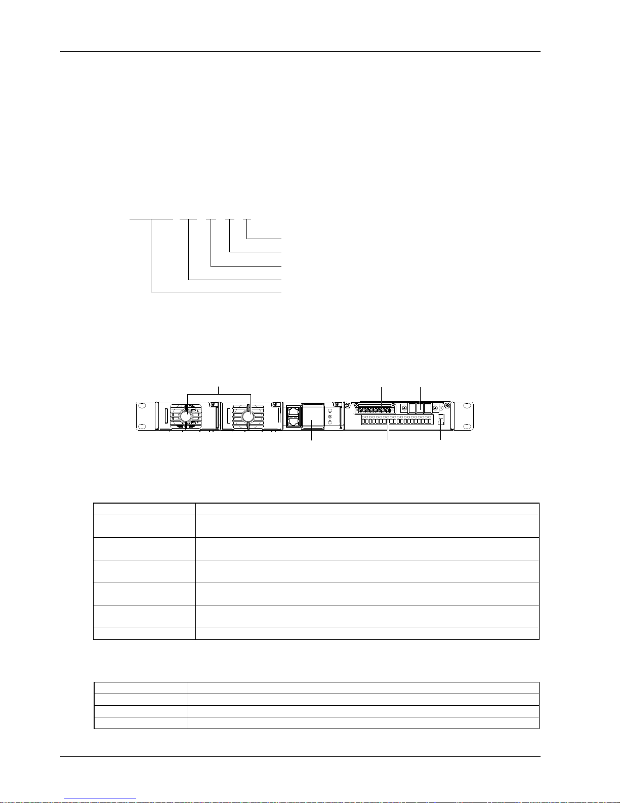
1.1 Model Description
The model description of the system is given in Figure 1-1.
NetSure 211 C 2
Region: China
Type of the rectifier: R48-1000
Brand name of the system
3
Version No.
The number of the rectifier in the typical power supply system: 2
Figure 1-1 Model description
1.2 Composition And Configuration
The appearance of the system is shown in Figure 1-2.
DI/DO/temperature probe terminals
AC input terminals
DC output terminals Battery terminalsMonitoring module
Rectifier
Figure 1-2 Appearance of the system
The configuration of the system is listed in Table 1-1.
Table 1-1 Configuration of the system
Component
Configuration
Rectifier
Model: R48-1000
Standard configuration: 2 pieces
Monitoring module
Model: M522B, M523B or M221B
Standard configuration: 1 piece
AC power distribution
AC input mode:
L + N + PE/220V
DC power distribution
10 load fuses:
8 ×10A, 2 × 20A
Battery routes
One battery fuse:
1 × 30A
Others
Two digital input ports, two dry contact output ports, two temperature sensor ports
The monitoring module is available in three different models. Their configurations are listed in Table 1-2.
Table 1-2 Configuration of the monitoring module
Models
Configuration
M522B
2DI + 2DO, LCD display, network port, RS232 port
M523B
2DI + 2DO, LCD display, RS232 port
M221B
2DI + 2DO, no LCD display, three indicators indicating operation status of the system, RS232 port
 Loading...