

Page 1
(E/W Spec. No. 588705000 Module Mounting Shelves)
(E/W Spec. No. 588705300 Module Mounting Shelves)
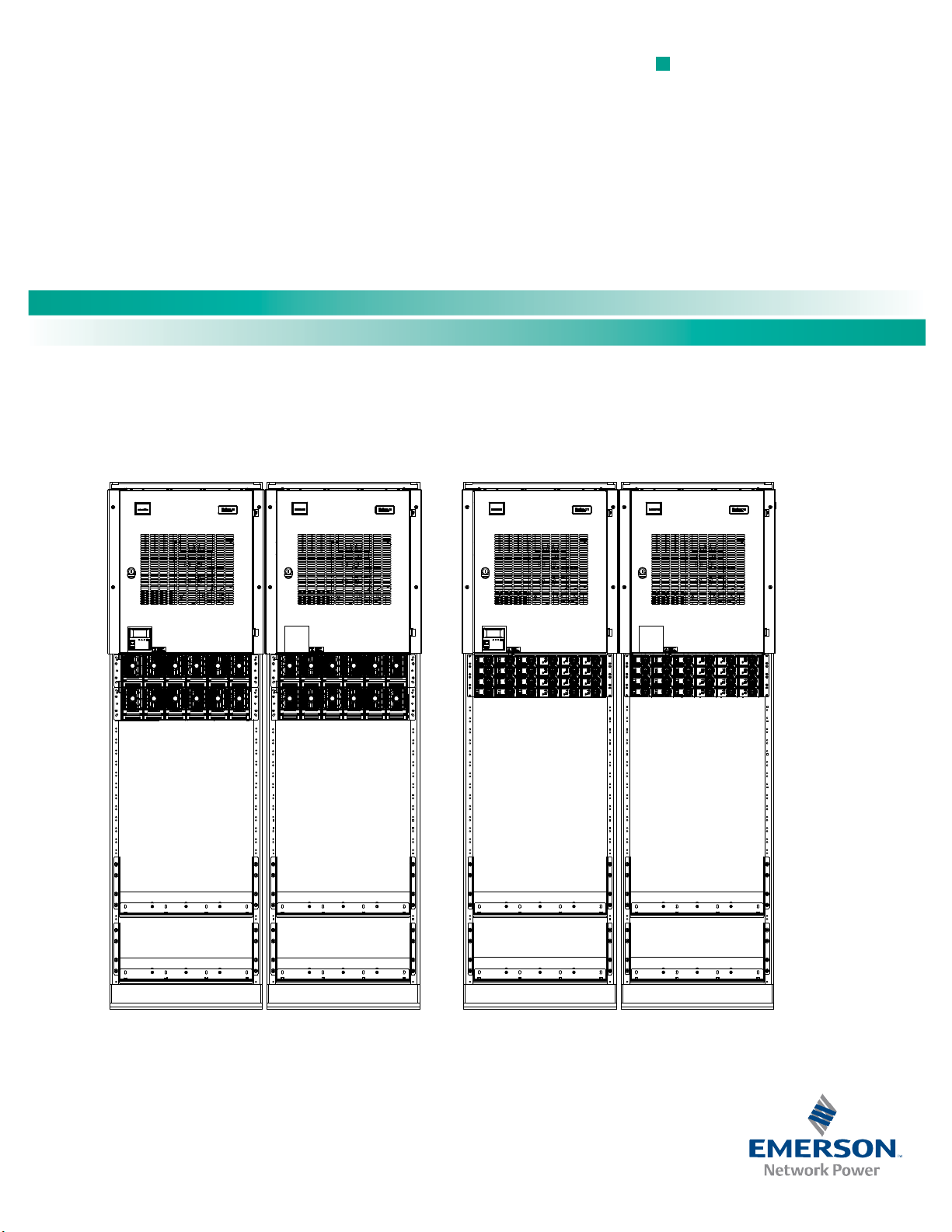
Main Bay Supplemental BayMain Bay Supplemental Bay
NetSure™ -48V DC Power System
Quick Start Guide, QS582127000 (Issue AC, December 10, 2013)
Specification Number: 582127000
Model Number: 721
NPBB
A Technical Manual from th
in Business-Critical Continu
s
rt
pe
x
e e
™
ty
i
Page 2

NetSure™ -48V DC Power System
Quick Start Guide, QS582127000 (Issue AC, December 10, 2013)
This page is intentionally blank.
Spec. No: 582127000 Code: QS582127000
Model No: 721NPBB Issue AC, December 10, 2013
Page 3

NetSure™ -48V DC Power System
[i]
Quick Start Guide, QS582127000 (Issue AC, December 10, 2013)
Table of Contents
Admonishments Used in this Document ................................................................................................................ ii
Important Safety Instructions .............................................................................................................................. iii
General Safety ........................................................................................................................................................iii
Voltages .................................................................................................................................................................iii
Battery ...................................................................................................................................................................iii
Personal Protective Equipment (PPE) .......................................................................................................................iv
Hazardous Voltage .................................................................................................................................................iv
Handling Equipment Containing Static Sensitive Components .................................................................................iv
Static Warning ...................................................................................................................................................... v
Customer Documentation Package ....................................................................................................................... 1
To Access Technical Documentation on the Web… .................................................................................................. 2
Physical Installation .............................................................................................................................................. 3
Install Distribution Devices.................................................................................................................................... 3
Make Jumper and Switch Settings ......................................................................................................................... 9
Electrical Connections ......................................................................................................................................... 10
Important Safety Instructions................................................................................................................................ 10
Make Frame Grounding Connections .................................................................................................................... 10
Make Nominal 208/240 Volts AC Input and Equipment Grounding Connections (if equipped) ................................ 10
Make Nominal 400 Volts DC Input and Equipment Grounding Connections (if equipped) ....................................... 18
Make External Interface Connections .................................................................................................................... 24
Make ACU+ Controller Ethernet Connection (if required) ....................................................................................... 41
Make Bay-to-Bay Communications Cable Connections .......................................................................................... 41
Installing Bay-to-Bay Busbars (582127000 List 1 with List 2 / List 3) ........................................................................ 41
Connecting Converter Output Cables 582127000 List 60....................................................................................... 45
Make Load Connections ........................................................................................................................................ 48
Make Battery Connections .................................................................................................................................... 56
List 93 Battery Tray ............................................................................................................................................... 63
Installing Rectifier or Converter Modules into Spec. No. 588705000 Module Mounting Shelves ........................... 63
Installing the Rectifier and Converter Modules into Spec. No. 588705300 Module Mounting Shelves ................... 65
Start and Check System ....................................................................................................................................... 67
NetPerform™ Optimization Services ................................................................................................................... 73
Spec. No: 582127000 Code: QS582127000
Model No: 721NPBB Issue AC, December 10, 2013
Page 4
NetSure™ -48V DC Power System
[ii]
DANGER!
if not avoided. (ANSI, OSHA)
WARNING!
serious injury if not avoided. This admonition is not used for situations that pose a risk on
equipment, software, data, or service. (ANSI)
CAUTION!
moderate injury if not avoided. (ANSI, OSHA) This admonition is not used for situations that pose a risk
only to equipment, data, or service, even if such use appears to be permitted in some of the applicable
standards. (OSHA)
ALERT!
data, or service. (ISO)
ALERT!
software corruption, data loss, or s
FIRE SAFETY!
locations of fire
SAFETY!
to a particular source of hazard or to fire safety. (ISO, ANSI, OSHA)
Quick Start Guide, QS582127000 (Issue AC, December 10, 2013)
Admonishments Used in this Document
Warns of a hazard the reader will be exposed to that will likely result in death or serious injury
D
an
g
er
Warns of a potential hazard the reader may be exposed to that could result in death or
W
ar
n
in
g
Warns of a potential hazard the reader may be exposed to that could result in minor or
ly to
Caution
A
lert
Alert
Fi
re Safet
S
afety
Alerts the reader to an action that must be avoided in order to protect equipment, software,
Alerts the reader to an action that must be performed in order to prevent equipment damage,
ervice interruption. (ISO)
Informs the reader of fire safety information, reminders, precautions, or policies, or of the
-fighting and fire-safety equipment. (ISO)
y
Informs the reader of general safety information, reminders, precautions, or policies not related
Spec. No: 582127000 Code: QS582127000
Model No: 721NPBB Issue AC, December 10, 2013
Page 5

NetSure™ -48V DC Power System
[iii]
Danger
Da
nger
Warning
Warnin
g
Dange
r
Dan
ger
Da
n
ge
r
Quick Start Guide, QS582127000 (Issue AC, December 10, 2013)
Important Safety Instructions
General Safety
DANGER!
YOU MUST FOLLOW APPROVED SAFETY PROCEDURES.
Performing the following procedures may expose you to
hazards. These procedures should be performed by
qualified technicians familiar with the hazards
associated with this type of equipment. These hazards
may include shock, energy, and/or burns. To avoid
these hazards:
a) The tasks should be performed in the order
indicated.
b) Remove watches, rings, and other metal objects.
c) Prior to contacting any uninsulated surface or
termination, use a voltmeter to verify that no
voltage or the expected voltage is present. Check
for voltage with both AC and DC voltmeters prior to
making contact.
d) Wear eye protection.
e) Use double insulated tools appropriately rated for
the work to be performed.
f) For 400V DC input systems, do not work on an
energized system without full arc flash and PPE
protection.
Voltages
AC Input Voltages
DANGER! This system may operate from AC input
voltage capable of producing fatal electrical shock. AC
input power must be completely disconnected from the
branch circuits wiring used to provide power to the
system before any AC electrical connections are made.
Follow local lockout/tagout procedures to ensure
upstream branch circuit breakers remain de-energized
during installation. DO NOT apply AC input power to
the system until all electrical connections have been
completed and checked.
DC Input Voltages
DANGER! This system may operate from 400V DC input
voltage capable of producing fatal electrical shock. DC
input power must be completely disconnected from the
branch circuits wiring used to provide power to the
system before any DC electrical connections are made.
Follow local lockout/tagout procedures to ensure
upstream branch circuit breakers remain de-energized
during installation. DO NOT apply DC input power to
the system until all electrical connections have been
completed and checked.
DC Output and Battery Voltages
DANGER! This system produces DC Power and may have
a battery source connected to it. Although the DC
voltage is not hazardously high, the rectifiers/converters
and/or battery can deliver large amounts of current.
Exercise extreme caution not to inadvertently contact or
have any tool inadvertently contact an output terminal
or battery terminal or exposed wire connected to an
output terminal or battery terminal. NEVER allow a
metal object, such as a tool, to contact more than one
termination or battery terminal at a time, or to
simultaneously contact a termination or battery
terminal and a grounded object. Even a momentary
short circuit can cause sparking, explosion, and injury.
DANGER! Follow local lockout/tagout procedures to
ensure DC branch circuit protection devices remain deenergized during installation at loads, as required.
Battery
WARNING! Correct polarity must be observed when
connecting battery leads.
WARNING! Special safety precautions are required for
procedures involving handling, installing, and servicing
batteries. Observe all battery safety precautions in this
manual and in the battery instruction manual. These
precautions should be followed implicitly at all times.
Spec. No: 582127000 Code: QS582127000
Model No: 721NPBB Issue AC, December 10, 2013
Page 6
NetSure™ -48V DC Power System
[iv]
W
a
rn
in
g
Danger
Danger
Dange
r
Alert
Alert
Quick Start Guide, QS582127000 (Issue AC, December 10, 2013)
WARNING! A battery can present a risk of electrical
shock and high short circuit current. Servicing of
batteries should be performed or supervised only by
properly trained and qualified personnel knowledgeable
about batteries and the required precautions.
The following precautions should be observed when
working on batteries:
• Remove watches, rings, and other metal objects.
• Eye protection should be worn to prevent injury
from accidental electrical arcs.
• Use certified and well maintained insulated tools.
Use double insulated tools appropriately rated for
the work to be performed. Ensure that wrenches
with more than one working end have only one end
exposed.
• Do not lay tools or metal parts on top of batteries.
• Disconnect charging source prior to connecting or
disconnecting battery terminals.
• Risk of explosion if battery is replaced with an
incorrect type or if polarity is reversed. When
replacing batteries, replace with the same
manufacturer and type, or equivalent.
• Dispose of used batteries according to the
instructions provided with the batteries. Do not
dispose of batteries in a fire. They may explode.
• ALWAYS FOLLOW THE BATTERY MANUFACTURER’S
RECOMMENDATIONS AND SAFETY INSTRUCTIONS.
In addition to the hazard of electric shock, gas produced
by batteries can be explosive and sulfuric acid can cause
severe burns. Do not open or mutilate batteries.
Released electrolyte is harmful to the skin and eyes, and
is toxic. If electrolyte comes into contact with skin, the
affected area should be washed immediately with large
amounts of water.
DANGER!
This equipment may be used in conjunction
with lead-acid batteries. Working near lead-acid
batteries is dangerous!
• Batteries contain sulfuric acid.
• Batteries generate explosive gases during normal
operation. Systems containing batteries should
never be installed in an airtight room or space.
Only install in a ventilated environment.
• Batteries are an energy source that can produce
high amounts of electrical current.
FOR THESE REASONS, IT IS OF CRITICAL IMPORTANCE
THAT YOU READ THESE INSTRUCTIONS AND FOLLOW
THEM EXACTLY.
WHEN WORKING WITH LEAD-ACID BATTERIES:
• Wear complete protection for eyes, face, hands,
and clothing. Examples are safety goggles or face
shield, a rubber apron and gloves.
• If battery acid enters your eye, immediately flush
your eye with running cold water for at least 15
minutes. Get medical attention immediately.
• If battery acid contacts skin or clothing, wash
immediately with soap and water.
ALERT! Performing maintenance and/or
troubleshooting procedures may interrupt power to the
loads, if battery reserve is not sufficient.
Personal Protective Equipment (PPE)
The following admonishments apply to 400V DC input systems.
DANGER! ARC FLASH AND SHOCK HAZARD.
Appropriate PPE and tools required when working on
this equipment. An appropriate flash protection
boundary analysis should be done determine the
“hazard/risk” category, and to select proper PPE.
This product is intended only for installation in a
Restricted Access Location.
Only authorized and properly trained personnel should
be allowed to install, inspect, operate, or maintain the
equipment.
Do not work on LIVE parts. If required to work or
operate live parts, obtain appropriate Energized Work
Permits as required by the local authority, per NFPA 70E
“Standard for Electrical Safety in the Workplace”.
Hazardous Voltage
DANGER! Hazard of electrical shock. More than one
disconnect may be required to de-energize the system
before servicing.
Handling Equipment Containing
Static Sensitive Components
ALERT! Installation or removal of equipment containing
static sensitive components requires careful handling.
Before handling any equipment containing static
sensitive components, read and follow the instructions
contained on the Static Warning Page.
Spec. No: 582127000 Code: QS582127000
Model No: 721NPBB Issue AC, December 10, 2013
Page 7

NetSure™ -48V DC Power System
[v]
Quick Start Guide, QS582127000 (Issue AC, December 10, 2013)
Static Warning
This equipment contains static sensitive components. The warnings listed below must be observed to prevent damage to these
components. Disregarding any of these warnings may result in personal injury or damage to the equipment.
1. Strictly adhere to the procedures provided in this document.
2. Before touching any equipment containing static sensitive components, discharge all static electricity from yourself by wearing
a wrist strap grounded through a one megohm resistor. Some wrist straps, such as Emerson Network Power Part Number
631810600, have a built-in one megohm resistor; no external resistor is necessary. Read and follow wrist strap manufacturer’s
instructions outlining use of a specific wrist strap.
3. Do not touch traces or components on equipment containing static sensitive components.
Handle equipment containing static sensitive components only by the edges that do not have connector pads.
4. After removing equipment containing static sensitive components, place the equipment only on conductive or anti-static
material such as conductive foam, conductive plastic, or aluminum foil. Do not use ordinary Styrofoam
5. Store and ship equipment containing static sensitive components only in static shielding containers.
6. If necessary to repair equipment containing static sensitive components, wear an appropriately grounded wrist strap, work on a
conductive surface, use a grounded soldering iron, and use grounded test equipment.
™
or ordinary plastic.
Spec. No: 582127000 Code: QS582127000
Model No: 721NPBB Issue AC, December 10, 2013
Page 8

NetSure™ -48V DC Power System
[vi]
Quick Start Guide, QS582127000 (Issue AC, December 10, 2013)
This page is intentionally blank.
Spec. No: 582127000 Code: QS582127000
Model No: 721NPBB Issue AC, December 10, 2013
Page 9

NetSure™ -48V DC Power System
[1]
Quick Start Guide, QS582127000 (Issue AC, December 10, 2013)
Customer Documentation Package
This document (QS582127000) provides Quick Start Instructions for NetSure™ -48V DC Power System Model 721NPBB, Spec. No.
582127000.
The complete Customer Documentation Package consists of…
NetSure
NetSure
USB Drive with All Customer Documentation
™
-48V DC Power System Installation Manual
• NetSure™ -48V DC Power System Quick Start Guide: QS582127000
• NetSure™ -48V DC Power System Quick Start Guide: QS582127000
™
ACU+ Controller User Manual
• NetSure™ ACU+ Controller User Instructions: UM1M820BNA (AC Input Voltage Systems) or UM1M820DNA400 (DC Input
Voltage Systems)
• Power System Quick Start Guide: QS582127000
• Power System Quick Start Guide: QS582127000
• Power System User Instructions: UM582127000
• Power System “System Application Guide”: SAG582127000
• Module Mounting Shelf Power Data Sheet: PD588705000
• Rectifier Instructions: UM1R483500E
• Converter Instructions: UM1C400483500E
• Module Mounting Shelf Power Data Sheet: PD588705300
• Rectifier Instructions: UM1R482000E3
• Converter Instructions: UM1C48241500
• Engineering Drawings
• Also provided on the USB drive is an ACU+ configuration drawing and the ACU+ configuration files loaded into the ACU+ as
shipped.
Spec. No: 582127000 Code: QS582127000
Model No: 721NPBB Issue AC, December 10, 2013
Page 10

NetSure™ -48V DC Power System
[2]
*
*
Quick Start Guide, QS582127000 (Issue AC, December 10, 2013)
To Access Technical Documentation on the Web…
To view and download technical documentation for your Emerson Network Power DC power products, please visit our secure partner
portal website, EnergyNet at www.EmersonEnergy.com.
Under Partner Login, click on “Request Account” to request access to this website. If you can’t remember your password, use the “Forgot
Password?” tool.
Once you log in, you arrive at the EnergyNet landing page
document you are looking for, use the request info button at the bottom of the screen.
For Users who require access to company specific documents, after logging into EnergyNet you will be
directed to a company specific landing page.
. Here you can search for product documentation. If you do not find the
Spec. No: 582127000 Code: QS582127000
Model No: 721NPBB Issue AC, December 10, 2013
Page 11
NetSure™ -48V DC Power System
[3]
Choose a mounting location
Secure the relay rack to the
floor
Securing the Relay Rack to the Floor in the
Mount the Power System
Mounting System Components in an Equipment Rack
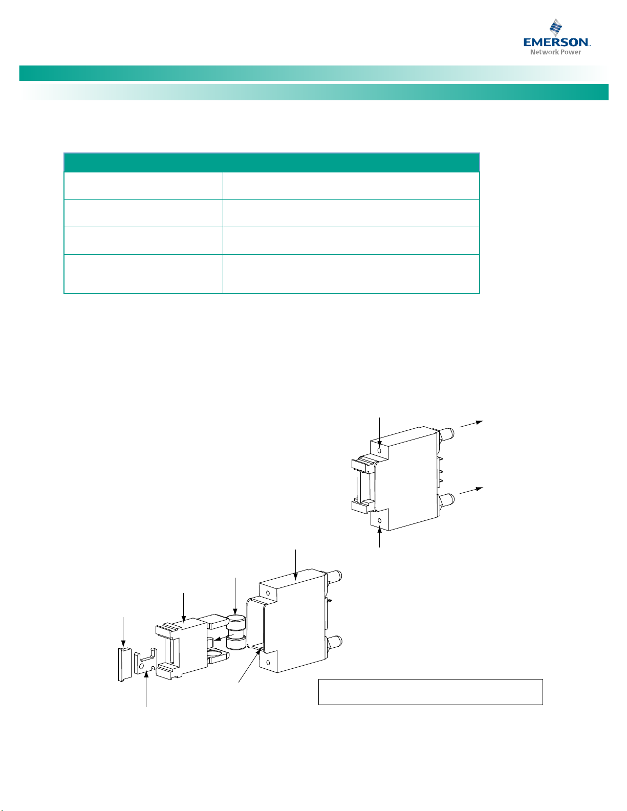
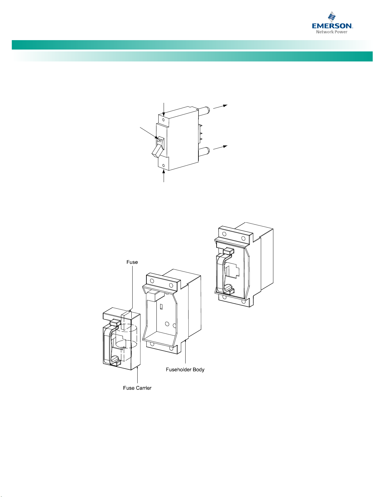
Fuseho
lde
r As
sembly
Longer Sid
e
to the Bot
tom
Sh
ort
er Si
de
to the Top
Fuse Carrie
r
Fus
eholder Body
T
PS/TL
S Fus
e
Polariz
ing Keyway
Matches Key on
Bot
tom of Fuse Carrier
Fuse
holder
Assembly
E
xploded View
Fuseholder Assem
bly (P/N 117201) incl
udes
body & car
rier, alarm fuse, and a
larm fuse safety cover.
Ins
ert t
hese terminals
into cor
res
pond
ing
soc
ket
s
on
dist
rib
ution panel.
GM
T-X
Safety Fuse
Cover
(Repla
cement
P/N 24889870
0)
GMT-18/100A
Al
arm Fuse
(Replacement
P/N 248610301)
Quick Start Guide, QS582127000 (Issue AC, December 10, 2013)
Physical Installation
To do this…
See this in the Installation Instructions (IM582127000)
General Requirements in the INSTALLING THE
SYSTEM section.
INSTALLING THE SYSTEM section.
in the INSTALLING THE SYSTEM section.
Install optional lug adapter
busbar kits
Installing Optional Lug Adapter Busbar Kits, Part Nos.
534449 and 514714 in the INSTALLING THE
SYSTEM section.
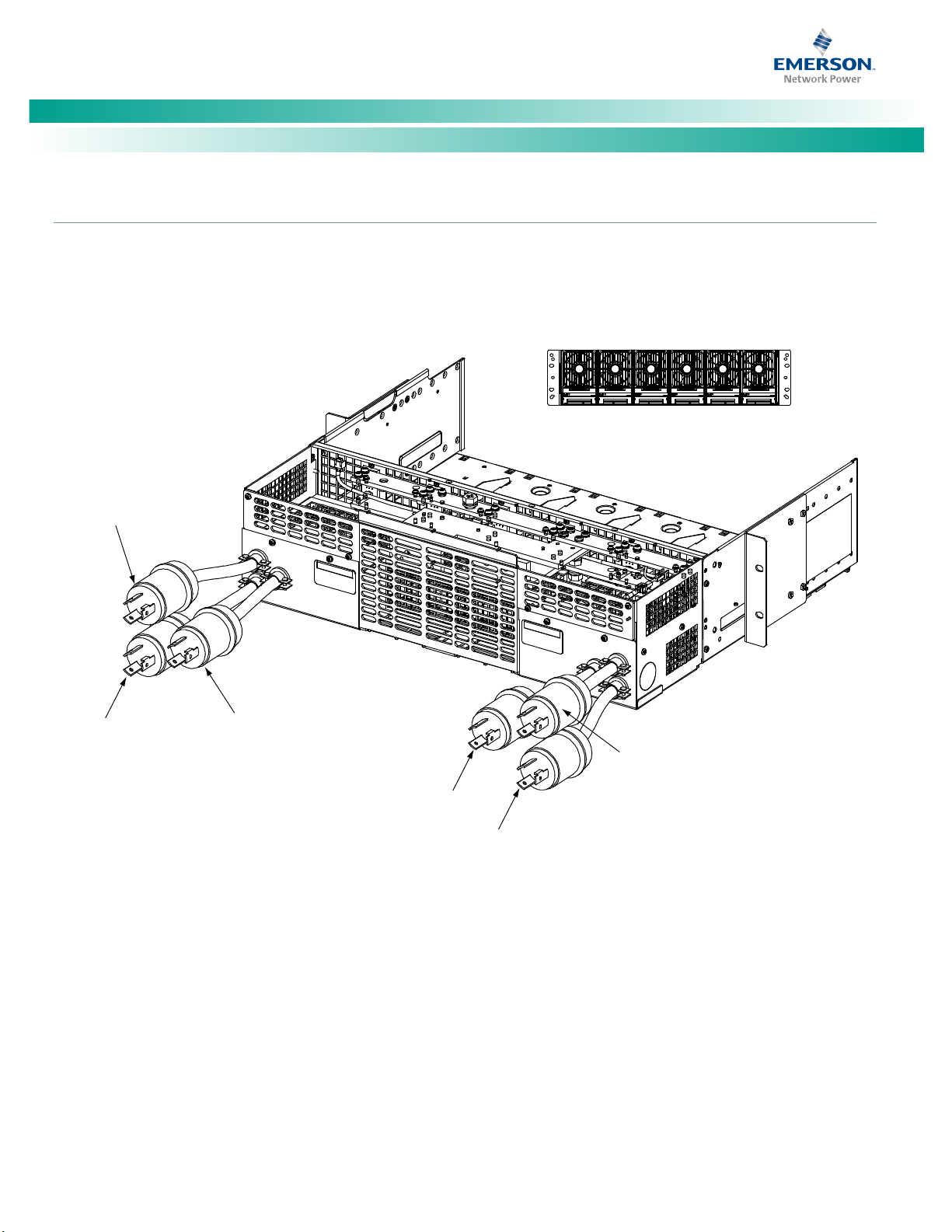
Install Distribution Devices
Load and battery distribution devices were factory-installed if ordered with the power system. If additional installation is required, refer
to Figure 1 through Figure 6. For detailed procedures, refer to Installing Circuit Breakers and Fuses in the INSTALLING THE SYSTEM section
of the Installation Instructions (IM582127000).
Figure 1. Installing a Bullet Nose Type Fuseholder and TPS/TLS Fuse
Spec. No: 582127000 Code: QS582127000
Model No: 721NPBB Issue AC, December 10, 2013
Page 12
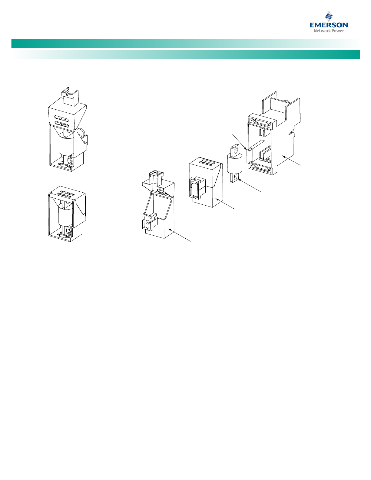
NetSure™ -48V DC Power System
[4]
Insert these terminals
into corresponding sockets
on distribution panel.
Longer Side
to the Bottom
Shorter Side
to the Top
Lettering on
handle must be
right side up.
Turn off
before installing.
Quick Start Guide, QS582127000 (Issue AC, December 10, 2013)
Figure 2. Installing a Bullet Nose Type Circuit Breaker
Figure 3. Installing a TPH Fuse
Spec. No: 582127000 Code: QS582127000
Model No: 721NPBB Issue AC, December 10, 2013
Page 13
NetSure™ -48V DC Power System
[5]
F
us
e C
ase
Open Fuse Case View
TPL F
use
Fuse
In
s
ta
ll
e
d i
n
Open Fuse C
as
e
(r
ear
vie
w)
Fuse Installed in
Closed Fuse Case
(rear view)
Fu
sebl
ock
(P/
N 51
6241)
GMT-18/100A Al
ar
m Fuse
(P/N 248610301) and
GMT-X Safety F
us
e
Cover
(P/N 248898700)
(Both ar
e
pr
ov
i
ded
w/ fusebloc
k
)
Quick Start Guide, QS582127000 (Issue AC, December 10, 2013)
Figure 4. Installing TPL-B Fuses
Spec. No: 582127000 Code: QS582127000
Model No: 721NPBB Issue AC, December 10, 2013
Page 14
NetSure™ -48V DC Power System
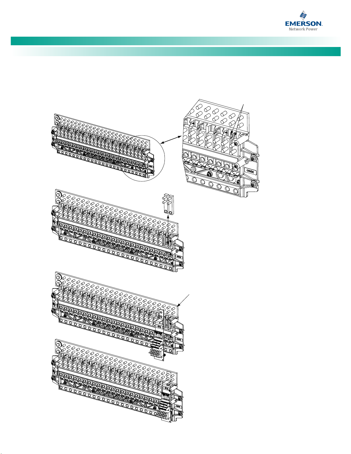
[6]
Press in tabs to release
lug terminal busbars for
positions to be occupied
by GMT Fuse Block.
Remove two lug terminal busbars
for positions to be occupied
by GMT Fuse Block.
Plug in GMT Fuse Block and secure
at two locations on the RTN bar.
Torque to 72 in-lbs.
RTN Bar
GMT Fuse Block Installed View
1.
2.
3.
Quick Start Guide, QS582127000 (Issue AC, December 10, 2013)
Figure 5. Installing an Optional Bullet Nose Type 6-Position GMT Distribution Fuse Block
Spec. No: 582127000 Code: QS582127000
Model No: 721NPBB Issue AC, December 10, 2013
Page 15
NetSure™ -48V DC Power System
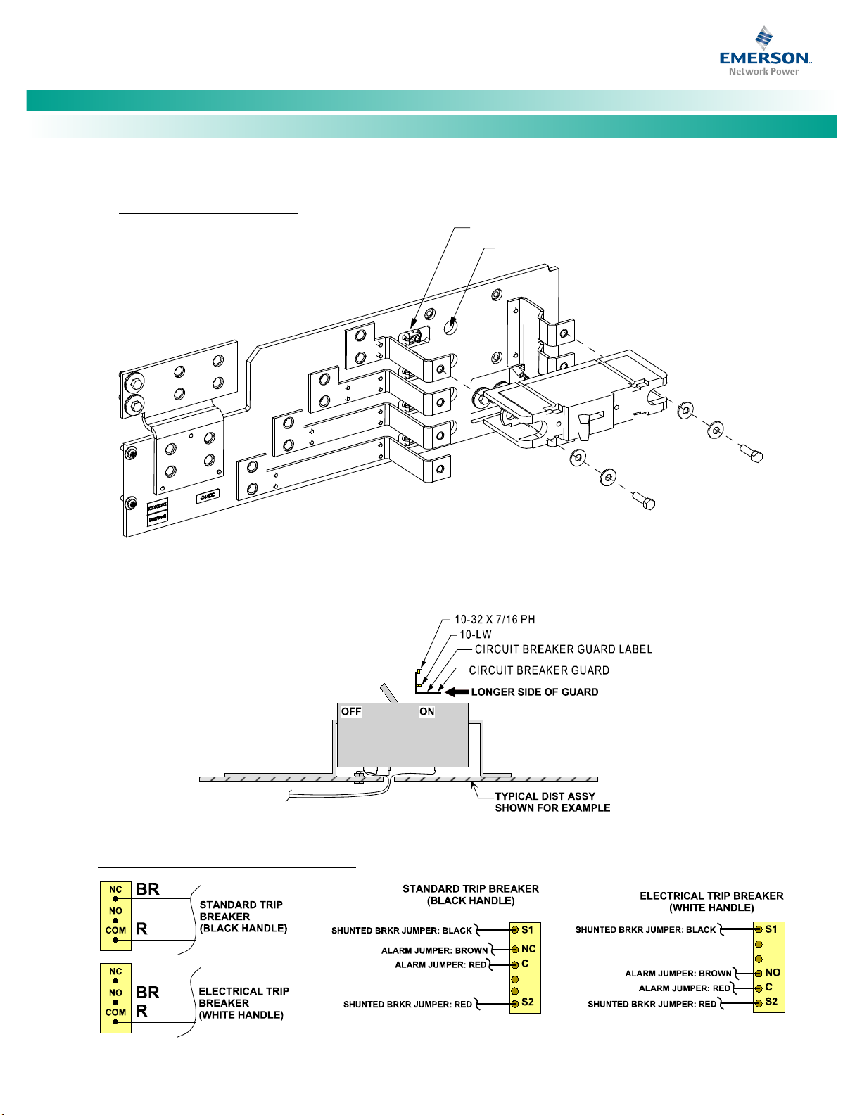
[7]
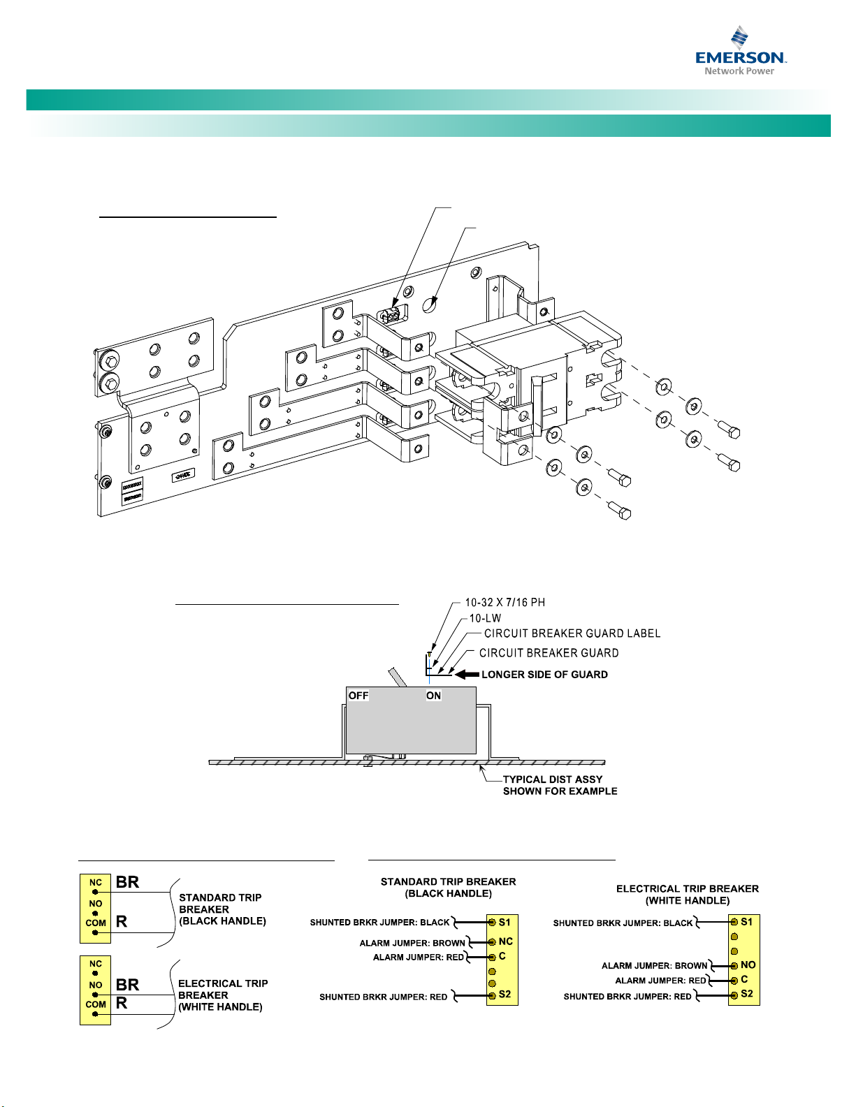
INSTALLING CIRCUIT BREAKER
A
Quick Start Guide, QS582127000 (Issue AC, December 10, 2013)
Figure 6. Installing a GJ/218 Circuit Breaker (1-Pole) (cont’d on next page)
Alarm jumper connector.
Holes to route shunt jumper through (if applicable).
ON
OFF
INSTALLING CIRCUIT BREAKER GUARD
LARM WIRING (BREAKERS W/OUT SHUNTS)
Apply anti-oxidizing compoun
surfaces before mounting circuit breakers.
ALARM WIRING (BREAKERS WITH SHUNTS)
d to
bar ma
bus
tin
4" H
1/
ard
ene
d
Fla
t Was
her
g
1/4" Belleville
Lock Washer
1/4-20 x 3/4” Bolt
(2 places)
Torque to 60 in-lbs.
Spec. No: 582127000 Code: QS582127000
Model No: 721NPBB Issue AC, December 10, 2013
Page 16
NetSure™ -48V DC Power System
[8]
Alarm jumper connectors.
A
Quick Start Guide, QS582127000 (Issue AC, December 10, 2013)
Figure 6. Installing a GJ/218 Circuit Breaker (2-Pole, 3-Pole, 4-Pole) (cont’d from previous page)
INSTALLING CIRCUIT BREAKER
2-pole breaker shown.
3-pole and 4-pole breakers similar.
Holes to route shunt jumper through (if applicable).
OFF
ON
Apply anti-oxidizing compound to busbar mating
surfaces before mounting circuit breakers.
INSTALLING CIRCUIT BREAKER GUARD
LARM WIRING (BREAKERS W/OUT SHUNTS)
Busbar
ALARM WIRING (BREAKERS WITH SHUNTS)
1/4" Hardened
Flat Washer
1/4" Belleville
Lock Washer
1/4-20 x 3/4” Bolt
(4 places / 2-pole brk,
6 places / 3-pole brk,
8 places / 4-pole brk)
Torque to 60 in-lbs.
Spec. No: 582127000 Code: QS582127000
Model No: 721NPBB Issue AC, December 10, 2013
Page 17
NetSure™ -48V DC Power System
[9]
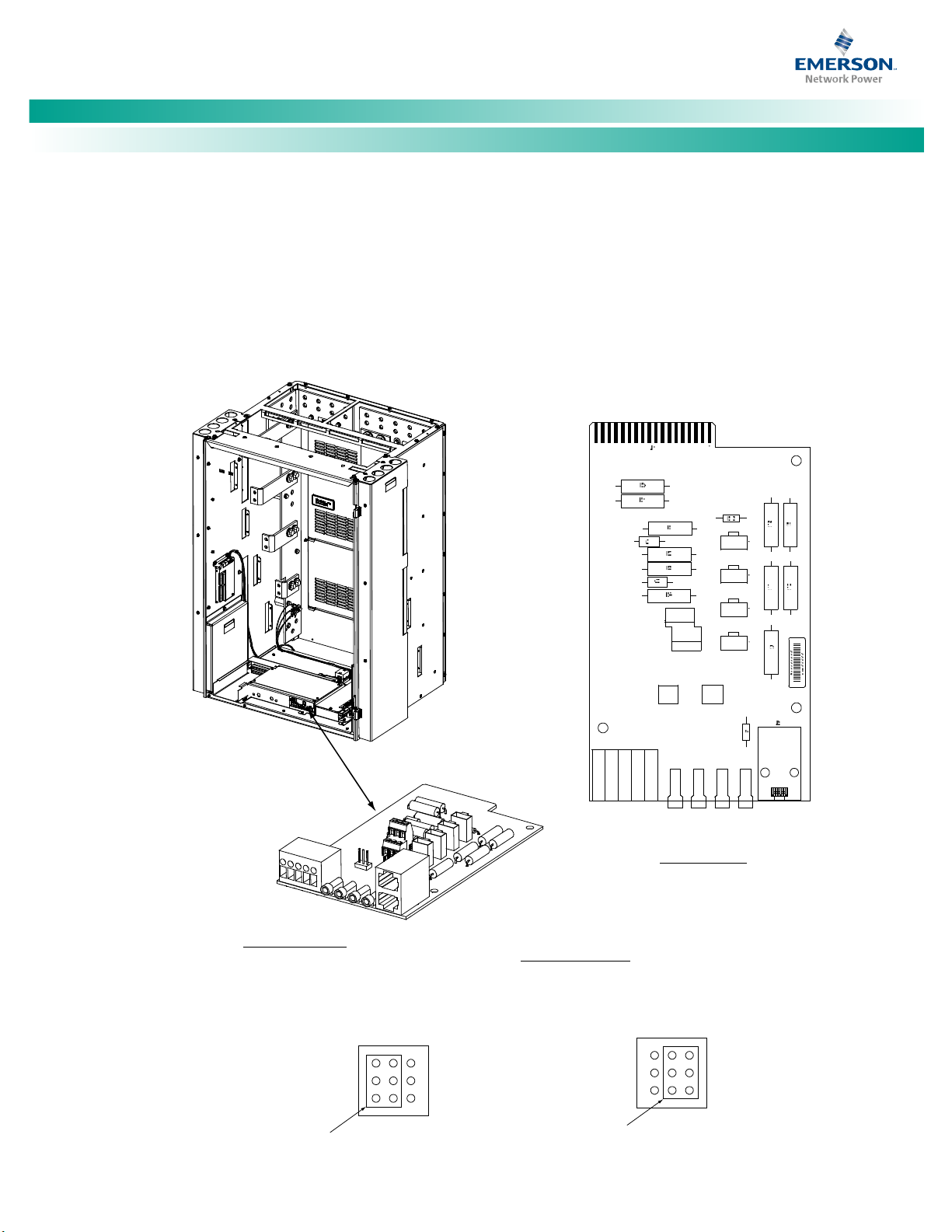
Switch Settings:
Jumper Settings:
J
8 (Mai
n Bay Onl
y)
Se
lects to
power Co
ntrolle
r
from “Ba
ttery P
ower” or no
t.
No
Batt
ery
Pw
r
B
attery
Pwr
External I
nterna
l
J8
J10
J10 (
Main Bay
Only)
B
attery M
onitor
ing Exter
nal / In
ternal
(see TB1
-4 and TB1
-5 for
ex
ternal m
onitor
ing points
)
1
2
3
7
8
9
1
2
3
7
8
9
Shorting Jumper
Shorting Jumpe
r
1
1A
2A 3A
1B
2B 3
B
5
J1
J2
J
3
J
4
J8
TB2
TB1
TP1 T
P2 T
P3 T
P4
J10
J5
T
B1-4
: External Batt
ery
Moni
tor
ing
(-)
TB1-5: E
xt
er
nal
Ba
ttery Moni
toring
(+)
4-R
ow C
abi
net
Shown,
O
the
rs S
imilar
(Fro
nt D
oor
Removed in
Illu
str
ati
on fo
r Clarity)
Syst
em Interf
ac
e
Circ
uit Car
d
(
Mai
n Bay Only
)
Quick Start Guide, QS582127000 (Issue AC, December 10, 2013)
Make Jumper and Switch Settings
Various circuit cards installed in the system have switch and jumper settings.
All switch settings set the various circuit cards to operate properly with this system and have been factory set.
The jumpers located on the system interface circuit card are customer selectable. Refer to Figure 7 for jumper locations
and function. Refer to SETTING JUMPERS AND SWITCH OPTIONS in the Installation Instructions (IM582127000) for a complete
procedure.
Figure 7. System Interface Circuit Card Jumper Locations
Spec. No: 582127000 Code: QS582127000
Model No: 721NPBB Issue AC, December 10, 2013
Page 18
NetSure™ -48V DC Power System
[10]
Danger!
Connection to Relay Rack
the MAKING ELECTRICAL CONNECTIONS section.
Connection
NOTE THAT THIS SYSTEM MAY BE EQUIPPED WITH AC OR DC INPUTS.
THESE PROCEDURES APPLY TO SYSTEMS WITH AC INPUTS.
SPECIFICALLY, THESE PROCEDURES APPLY TO THE FOLLOWING EQUIPMENT:
D
a
n
g
e
r
Quick Start Guide, QS582127000 (Issue AC, December 10, 2013)
Electrical Connections
Important Safety Instructions
Adhere to the “Important Safety Instructions” presented at the front of this document.
Make Frame Grounding Connections
To do this…
Make Frame Grounding
Make Central Office Ground
See this in the Installation Instructions (IM582127000)
Relay Rack Grounding Connection (Frame Ground) in
Central Office Ground Connection in the MAKING
ELECTRICAL CONNECTIONS section.
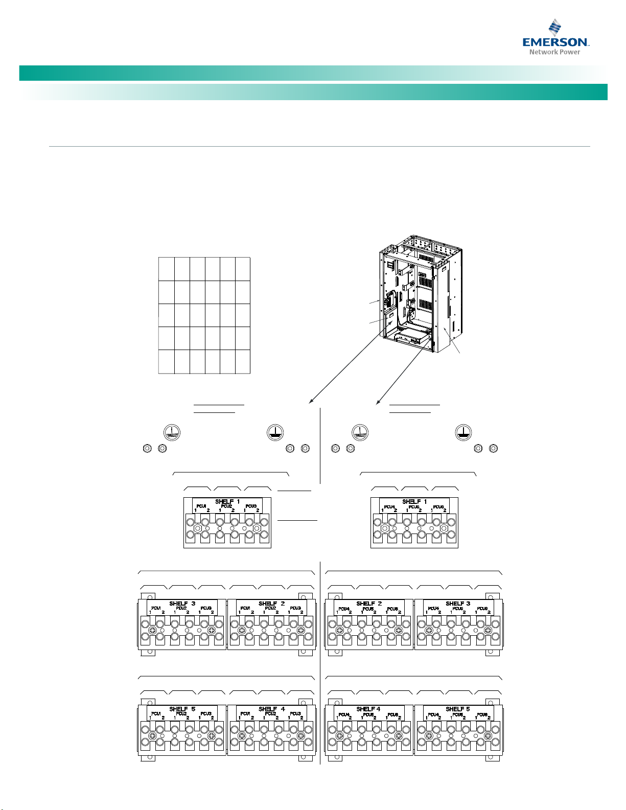
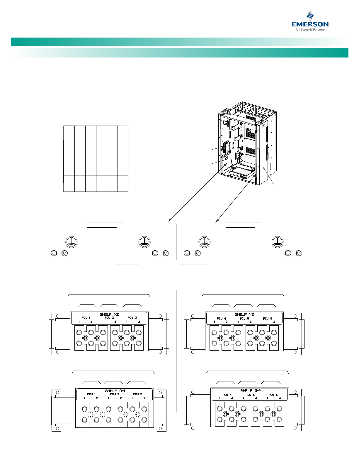
Make Nominal 208/240 Volts AC Input and Equipment Grounding Connections (if equipped)
Refer to Nominal 208/240 Volts AC Input and Equipment Grounding Connections (if equipped) in the MAKING ELECTRICAL CONNECTIONS
section of the Installation Instructions (IM582127000) for a complete procedure.
• 582127000 List 40, 41, 42
• 588705000 List 22
• 588705000 List 31
• 588705000 List 32
• 588705300 List 3
The available AC input options for this system are:
AC Input Termination Assemblies
• The system can be equipped with an AC input termination assembly which provides a separate single phase AC input
connection for each rectifier position (582127000 List 40).
• The system can be equipped with an AC input termination assembly which provides a separate single phase AC input
connection for every two (2) rectifier positions (582127000 List 41).
• The system can be equipped with an AC input termination assembly which provides a separate three phase AC input connection
for every three (3) rectifier positions (582127000 List 42).
Direct AC Input Connections to the Module Mounting Shelves
• The system can be equipped with module mounting shelves that contain AC input terminal blocks which provide a separate
single phase AC input connection for each rectifier position (588705000 List 31).
• The system can be equipped with module mounting shelves that contain AC input terminal blocks which provide a separate
three phase AC input connection for every three (3) rectifier positions (588705000 List 32).
• The system can be equipped with module mounting shelves that contain AC input line cords (one for each rectifier module
position) (588705000 List 22).
• The system can be equipped with module mounting shelves that contain AC input cable assemblies which provide a separate
single phase AC input connection for every two (2) rectifier positions (588705300 List 3).
Spec. No: 582127000 Code: QS582127000
Model No: 721NPBB Issue AC, December 10, 2013
Page 19
[11]
Note:
(4
-R
o
w C
a
bi
ne
t
Sh
ow
n
,
O
t
he
rs
S
im
il
a
r)
F
ro
nt
D
oo
r
Re
mo
v
ed
in
Illu
st
r
at
io
n
fo
r C
l
ar
i
ty
A
C I
NP
U
T C
ON
N
EC
T
IO
NS
,
1 F
E
ED
PE
R
1 R
EC
T
IF
IE
R
, S
I
NG
LE
P
HA
SE
(
58
2
12
70
0
0 L
IS
T
40
)
N
OT
E
:
W
I
RI
NG
T
O A
F
IE
LD
I
NS
TA
L
LE
D
SH
EL
F
IS
DO
N
E A
T
TH
E R
E
AR
O
F
TH
E S
H
EL
F.
A
C W
i
re
w
ay
Co
ver
AC
W
ir
ew
a
y
C
ove
r
A
C I
n
pu
t
Con
nec
tor
Cover
I
nsi
de
Vi
e
w
Le
ft S
ide
Ins
ide
View
Rig
ht Si
de
G
ND G
ND
GND
GND
AC 2AC
1
P
CU 1
A
C 2A
C 1
PC
U 2
AC
2AC
1
PC
U 3
R
ECTI
FIE
R
(P
CU
)
AC
INP
UT FE
EDS
1 FE
ED P
ER
1 RECTI
FIE
R (P
CU
)
208
-24
0VA
C, 50
/60
Hz,
SING
LE P
HAS
E
SHE
LF 1
AC
2AC 1
P
CU 1
AC 2AC 1
PCU 2
AC
2AC 1
PCU 3
AC
2AC 1
PCU
1
AC 2A
C 1
PCU
2
AC 2AC
1
PCU 3
REC
TIF
IER (
PCU
) AC
INPU
T FEEDS
1
FEE
D PE
R 1 RE
CTIFIE
R (PCU)
208-24
0VAC, 50/
60H
z, S
ING
LE PH
ASE
S
HELF
3 SHE
LF 2
AC 2AC 1
PCU
1
AC 2AC
1
PCU 2
AC 2AC 1
P
CU 3
AC 2A
C 1
PCU 1
AC 2
AC 1
PCU 2
AC 2AC 1
PCU 3
RECTIF
IER (PCU
) AC INPU
T FEEDS
1
FEED PE
R 1 RECTI
FIER (P
CU)
208
-240VAC
, 50/60H
z, SING
LE PHASE
SHELF 5 SHE
LF 4
A
C 2AC
1
PC
U 4
A
C 2AC
1
P
CU 5
AC 2A
C 1
PCU
6
R
EC
TI
FI
ER (PCU
) AC I
N
PU
T
FE
ED
S
1 F
EED
PER 1
REC
TIF
IE
R (
PCU)
208
-24
0VA
C, 50
/60
Hz,
SING
LE P
HAS
E
S
HEL
F 1
AC 2A
C 1
P
CU 4
AC 2AC 1
PCU
5
AC 2A
C 1
PCU 6
AC 2A
C 1
PCU 4
AC 2
AC 1
P
CU 5
AC 2AC 1
PCU 6
R
ECTIFIER
(PC
U) AC
INP
UT F
EED
S
1 FEE
D PER
1 RE
CTI
FIE
R (PC
U)
208
-240VA
C, 50/60
Hz, SINGL
E PH
ASE
SHELF 2 S
HELF 3
AC 2A
C 1
PCU 4
AC 2
AC 1
PCU 5
AC 2AC 1
PCU
6
AC 2AC 1
PC
U 4
AC 2AC 1
PCU 5
AC 2AC 1
P
CU 6
R
ECTIFIE
R (PCU)
AC INPUT
FEEDS
1 F
EED PER 1
RECTIF
IER (PCU
)
208-2
40VAC,
50/60Hz
, SINGLE
PHASE
S
HELF 4 SHE
LF 5
L
ine t
o L
in
e:
Co
nne
ct Li
ne 1
to T
erm
inal
1.
Conn
ect
Lin
e 2 to
Ter
min
al 2
.
Lin
e to
Neu
tral
Conn
ect
Lin
e to
Term
ina
l 1.
Con
nec
t Neu
tra
l to
Term
ina
l 2.
W
ire S
ize
Cap
aci
ty: 1
0-2
4 AWG.
R
ecom
men
ded
Tor
que: 10
in-lbs
.
F
RAM
E GR
OUN
D
CO
NNE
CT
I
ON
Fo
ur 1
0-32
X 3/
4"
Stu
d
s a
nd
H
ar
d
war
e.
Reco
mme
nde
d tor
qu
e
:
23
i
n-
lb
s
.
FRAM
E GR
OUN
D
CO
NNECT
ION
Fou
r 10
-32
X 3/
4"
Studs a
nd H
a
rd
w
ar
e.
Re
com
men
ded t
orq
ue:
23
in
-l
bs
.
Rec
tif
i
er
Mo
d
ul
e (
P
CU
) M
o
un
ti
ng Sl
ots
S
he
l
f #
1
Re
ct
.
(
PC
U)
1
R
ec
t
.
(P
C
U)
2
R
ec
t.
(
P
CU
)
3
Re
c
t.
(
PC
U
)
4
R
e
ct
.
(P
C
U)
5
R
ec
t
.
(P
CU
)
6
R
ec
t.
(PCU)
1
R
ec
t.
(
PC
U)
2
R
e
ct
.
(
P
CU
)
3
Re
ct
.
(
P
CU
)
4
Re
ct.
(
P
CU
)
5
Re
ct.
(
P
CU
)
6
Re
ct.
(P
C
U)
1
Rect.
(P
CU)
2
Rec
t.
(PC
U)
3
R
e
ct
.
(PCU
)
4
Re
ct
.
(PC
U)
5
R
e
ct
.
(PCU
)
6
R
ect.
(PC
U)
1
Rect.
(PCU
)
2
Re
ct.
(P
CU)
3
Re
c
t.
(PC
U)
4
Re
c
t.
(PCU)
5
Re
c
t.
(PC
U)
6
Rec
t.
(
P
CU
)
1
R
ect
.
(
PC
U)
2
Rect
.
(
PCU)
3
Rect.
(PC
U)
4
Re
ct.
(P
CU)
5
Re
ct
.
(PCU
)
6
Sh
el
f
#2
Sh
e
lf
#
3
S
he
l
f #
4
S
hel
f #5
NetSure™ -48V DC Power System
Quick Start Guide, QS582127000 (Issue AC, December 10, 2013)
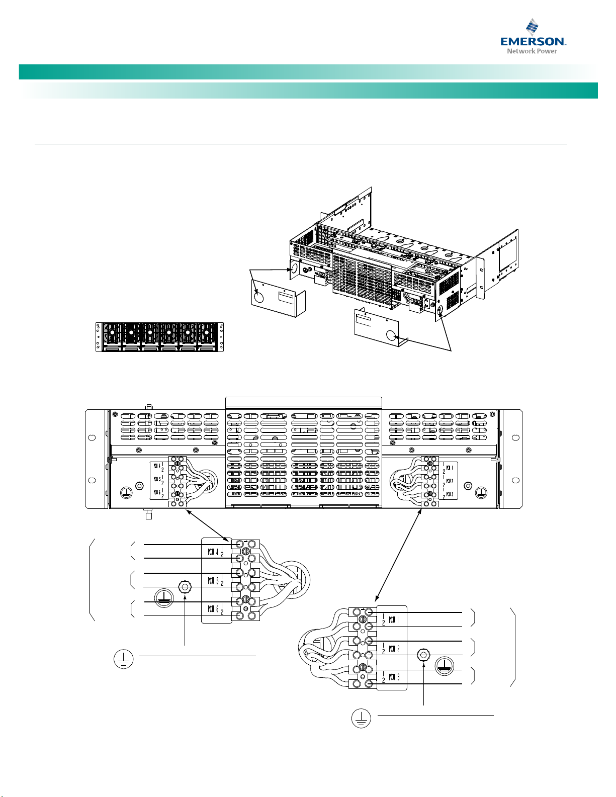
Connections to AC Input Termination Assemblies (582127000 List 40, 41, and 42)
Refer to Figure 8, Figure 9, or Figure 10.
Terminal blocks for a system with maximum possible rectifier shelves shown. Your system may have less terminal blocks then shown.
Figure 8. Nominal 208/240 Volts AC Input and Equipment Grounding Connections to AC Input Termination Assembly 582127000 List 40
(1 Feed per 1 Rectifier, Single Phase)
Spec. No: 582127000 Code: QS582127000
Model No: 721NPBB Issue AC, December 10, 2013
Page 20
NetSure™ -48V DC Power System
[12]
(4-Row Cabinet Shown,
Others Similar)
Front Door Removed in
Illustration for Clarity
AC INPUT CONNECTIONS,
1 FEED PER 2 RECTIFIERS, SINGLE PHASE
(582127000 LIST 41)
Inside View
Left Side
Inside View
Right Side
NOTE:
WIRING TO A FIELD INSTALLED
SHELF IS DONE AT THE REAR
OF THE SHELF.
GND GND GND GND
AC 2AC 1
PCU 1
AC 2AC 1
PCU 2
AC 2AC 1
PCU 3
RECTIFIER (PCU) AC INPUT FEEDS
1 FEED PER 2 RECTIFIERS (PCU)
208-240VAC, 50/60Hz, SINGLE PHASE
SHELVES 1 AND 2
AC 2AC 1
PCU 4
AC 2AC 1
PCU 5
AC 2AC 1
PCU 6
RECTIFIER (PCU) AC INPUT FEEDS
1 FEED PER 2 RECTIFIERS (PCU)
208-240VAC, 50/60Hz, SINGLE PHASE
SHELVES 1 AND 2
AC 2AC 1
PCU 1
AC 2AC 1
PCU 2
AC 2AC 1
PCU 3
RECTIFIER (PCU) AC INPUT FEEDS
1 FEED PER 2 RECTIFIERS (PCU)
208-240VAC, 50/60Hz, SINGLE PHASE
SHELVES 3 AND 4
AC 2AC 1
PCU 4
AC 2AC 1
PCU 5
AC 2AC 1
PCU 6
RECTIFIER (PCU) AC INPUT FEEDS
1 FEED PER 2 RECTIFIERS (PCU)
208-240VAC, 50/60Hz, SINGLE PHASE
SHELVES 3 AND 4
AC Wireway
Cover
AC Wireway
Cover
AC Input
Connector Cover
FRAME GROUND
CONNECTION
Four 10-32 X 3/4"
Studs and Hardware.
Recommended torque:
23 in-lbs.
FRAME GROUND
CONNECTION
Four 10-32 X 3/4"
Studs and Hardware.
Recommended torque:
23 in-lbs.
Line to Line:
Connect Line 1 to Terminal 1.
Connect Line 2 to Terminal 2.
Line to Neutral
Connect Line to Terminal 1.
Connect Neutral to Terminal 2.
Wire Size Capacity: 6-14 AWG.
Recommended Torque: 18 in-lbs.
Rectifier Module (PCU) Mounting Slots
Shelf #1
Rect.
(PCU)
1
Rect.
(PCU)
2
Rect.
(PCU)
3
Rect.
(PCU)
4
Rect.
(PCU)
5
Rect.
(PCU)
6
Rect.
(PCU)
1
Rect.
(PCU)
2
Rect.
(PCU)
3
Rect.
(PCU)
4
Rect.
(PCU)
5
Rect.
(PCU)
6
Rect.
(PCU)
1
Rect.
(PCU)
2
Rect.
(PCU)
3
Rect.
(PCU)
4
Rect.
(PCU)
5
Rect.
(PCU)
6
Rect.
(PCU)
1
Rect.
(PCU)
2
Rect.
(PCU)
3
Rect.
(PCU)
4
Rect.
(PCU)
5
Rect.
(PCU)
6
Shelf #2
Shelf #3
Shelf #4
Quick Start Guide, QS582127000 (Issue AC, December 10, 2013)
Figure 9. Nominal 208/240 Volts AC Input and Equipment Grounding Connections to AC Input Termination Assembly 582127000 List 41
(1 Feed per 2 Rectifiers, Single Phase)
Spec. No: 582127000 Code: QS582127000
Model No: 721NPBB Issue AC, December 10, 2013
Page 21
NetSure™ -48V DC Power System
[13]
(4-Row Cabinet Shown,
Others Similar)
Front Door Removed in
Illustration for Clarity
AC INPUT CONNECTIONS,
1 FEED PER 3 RECTIFIERS, THREE PHASE
(582127000 LIST 42)
Inside View
Left Side
Inside View
Right Side
NOTE:
WIRING TO AFIELD INSTALLED
SHELF IS DONE AT THE REAR
OF THE SHELF.
GND GND
GND GND
AC Wireway
Cover
AC Wireway
Cover
AC Input
Connector Cover
A B C
RECTIFIER (PCU) AC INPUT FEEDS
1 FEED PER 3 RECTIFIERS (PCU)
208-240VAC, 50/60Hz, THREE PHASE
SHELF 1 - PCUs #1 - #3
A B C
RECTIFIER (PCU) AC INPUT FEEDS
1 FEED PER 3 RECTIFIERS (PCU)
208-240VAC, 50/60Hz, THREE PHASE
SHELF 3 - PCUs #1 - #3
A B C
SHELF 2 - PCUs #1 - #3
A B C
RECTIFIER (PCU) AC INPUT FEEDS
1 FEED PER 3 RECTIFIERS (PCU)
208-240VAC, 50/60Hz, THREE PHASE
SHELF 5 - PCUs #1 - #3
A B C
SHELF 4 - PCUs #1 - #3
C B A
RECTIFIER (PCU) AC INPUT FEEDS
1 FEED PER 3 RECTIFIERS (PCU)
208-240VAC, 50/60Hz, THREE PHASE
SHELF 1 - PCUs #4 - #6
C B A
RECTIFIER (PCU) AC INPUT FEEDS
1 FEED PER 3 RECTIFIERS (PCU)
208-240VAC, 50/60Hz, THREE PHASE
SHELF 2 - PCUs #4 - #6
C B A
SHELF 3 - PCUs #4 - #6
C B A
RECTIFIER (PCU) AC INPUT FEEDS
1 FEED PER 3 RECTIFIERS (PCU)
208-240VAC, 50/60Hz, THREE PHASE
SHELF 4 - PCUs #4 - #6
C B A
SHELF 5 - PCUs #4 - #6
FRAME GROUND
CONNECTION
Four 10-32 X 3/4"
Studs and Hardware.
Recommended torque:
23 in-lbs.
FRAME GROUND
CONNECTION
Four 10-32 X 3/4"
Studs and Hardware.
Recommended torque:
23 in-lbs.
Wire Size Capacity: 6-14 AWG.
Recommended Torque: 18 in-lbs.
Rectifier Module (PCU) Mounting Slots
Shelf #1
Rect.
(PCU)
1
Rect.
(PCU)
2
Rect.
(PCU)
3
Rect.
(PCU)
4
Rect.
(PCU)
5
Rect.
(PCU)
6
Rect.
(PCU)
1
Rect.
(PCU)
2
Rect.
(PCU)
3
Rect.
(PCU)
4
Rect.
(PCU)
5
Rect.
(PCU)
6
Rect.
(PCU)
1
Rect.
(PCU)
2
Rect.
(PCU)
3
Rect.
(PCU)
4
Rect.
(PCU)
5
Rect.
(PCU)
6
Rect.
(PCU)
1
Rect.
(PCU)
2
Rect.
(PCU)
3
Rect.
(PCU)
4
Rect.
(PCU)
5
Rect.
(PCU)
6
Rect.
(PCU)
1
Rect.
(PCU)
2
Rect.
(PCU)
3
Rect.
(PCU)
4
Rect.
(PCU)
5
Rect.
(PCU)
6
Shelf #2
Shelf #3
Shelf #4
Shelf #5
Quick Start Guide, QS582127000 (Issue AC, December 10, 2013)
Figure 10. Nominal 208/240 Volts AC Input and Equipment Grounding Connections to AC Input Termination Assembly 582127000 List 42
(1 Feed per 3 Rectifiers, Three Phase)
Spec. No: 582127000 Code: QS582127000
Model No: 721NPBB Issue AC, December 10, 2013
Page 22
NetSure™ -48V DC Power System
[14]
Holes for 3/4"
Conduit Fitting
(AC Input)
Hol
es f
or 3/4"
C
ondu
it F
itting
(AC I
npu
t)
R
ear
Vie
w
Rear View
FRAME GROUND CONNECTION
ONE 10-32 X 3/4" STU
D
AN
D H
ARDWARE.
Recommended torque: 23 in-l
bs.
FRAME GROUND CONNECTION
ONE 10-32 X 3/4" STUD
AND HARDWARE.
Recommended torque: 23 in-lbs.
Re
ct
i
fi
er
M
od
ule
(PC
U) M
oun
ting Slots
(
f
ro
nt vi
ew)
Re
c
t.
(P
CU)
1
Re
ct.
(P
CU)
2
Re
ct.
(
PCU)
3
Re
ct.
(
PCU)
4
Rec
t.
(PCU)
5
Rect.
(PCU)
6
1
2
1
2
AC
IN
Rec
tifier
Modu
le 4
1
2
Rect
ifie
r
Module 5
Rectifier
Modul
e 6
AC
IN
Rectifier
Mod
ule 1
Rectifier
Module 2
Rectifier
Module 3
1
2
1
2
1
2
RECTIFIER (PCU) AC INPUT FEEDS
INDIVIDUAL RECTIFIER (PCU) FEED
208-240VAC, 50/6
0Hz, SINGLE PHASE
Wire Siz
e Capacity: 10-24 AWG.
Recommended Torque: 10 in-lbs.
Wire Size Capacity: 10-2
4 A
WG.
Recommended Torque: 10 in-lbs.
Quick Start Guide, QS582127000 (Issue AC, December 10, 2013)
Direct AC Input Connections to 588705000 List 31 Module Mounting Shelves
Refer to Figure 11.
Figure 11. Nominal 208/240 Volts AC Input Connections (Single-Phase) to a 588705000 List 31 Module Mounting Shelf
Spec. No: 582127000 Code: QS582127000
Model No: 721NPBB Issue AC, December 10, 2013
Page 23
NetSure™ -48V DC Power System
[15]
(ØA)
(ØB)
(ØC)
(
Ø
A
)
(
Ø
B
)
(
Ø
C
)
Holes for 3/4"
Conduit Fitting
(AC Input)
Holes for 3/4"
Conduit Fitting
(AC Input)
Rear View
Rear View
FRAME GROUND CONNECTION
ONE 10-32 X 3/4" STUD
AND HARDWARE.
Recommended torque: 23 in-lbs.
F
R
A
M
E
G
R
O
U
N
D
C
O
N
N
E
C
T
I
O
N
O
N
E
1
0
-
3
2
X
3
/
4
"
S
T
U
D
A
N
D
H
A
R
D
W
A
R
E
.
R
e
c
o
m
m
e
n
d
e
d
t
o
r
q
u
e
:
2
3
i
n
-
l
b
s
.
Rectifier Module (PCU) Mounting Slots
(front view)
Rect.
(PCU)
1
Rect.
(PCU)
2
Rect.
(PCU)
3
Rect.
(PCU)
4
Rect.
(PCU)
5
Rect.
(PCU)
6
AC IN
Feed 2
(Rectifier
Modules
4-6)
AC IN
Feed 1
(Rectifier
Modules
1-3)
1 (ØA) 2 (ØB) 3 (ØC) 1 (ØA ) 2 (ØB) 3 (ØC)
L1 L2
L1 L2
L1 L2
L1 L2
L1 L2
L1 L2
CONNECTIONS WITHIN THE SHELF
Mounting
Position
Rect 1
Rect 2
Rect 3
Rect 4
Rect 5
Rect 6
TB1, Terminal TB2, Terminal
RECTIFIER (PCU) AC INPUT FEEDS
1 FEED PER 3 RECTIFIERS (PCU)
208-240VAC, 50/60Hz, THREE PHASE
Wire Size Capacity: 6-14 AWG.
Recommended Torque: 18 in-lbs.
Wire Size Capacity: 6-14 AWG.
Recommended Torque: 18 in-lbs.
Quick Start Guide, QS582127000 (Issue AC, December 10, 2013)
Direct AC Input Connections to 588705000 List 32 Module Mounting Shelves
Refer to Figure 12.
Figure 12. Nominal 208/240 Volts AC Input Connections (Three-Phase) to a 588705000 List 32 Module Mounting Shelf)
Spec. No: 582127000 Code: QS582127000
Model No: 721NPBB Issue AC, December 10, 2013
Page 24
NetSure™ -48V DC Power System
[16]
Re
cti
fier
Mod
ule
4
Rect
ifi
er
Modu
le 6
Rec
tifi
er
M
odu
le 5
Re
cti
fier
Mod
ule
1
Rectifier
Mo
dule 3
Re
cti
fie
r
Module
2
Rear
Vie
w
R
e
ct
if
i
er
Mo
d
ul
e
(PCU) Mounting Slots
(
fr
on
t
vi
ew
)
Re
ct
.
(PCU)
1
R
e
ct
.
(PCU)
2
Rect.
(PC
U)
3
Rect.
(P
C
U)
4
Rect.
(
P
CU
)
5
Rect.
(
PC
U)
6
RE
CTI
FIE
R (P
CU) AC INPUT FEED
S
INDIV
IDU
AL RE
CTI
FIE
R (PCU) FEED
20
8-24
0VA
C, 50/60Hz, SINGLE P
HAS
E
Quick Start Guide, QS582127000 (Issue AC, December 10, 2013)
Direct AC Input Connections to 588705000 List 22 Module Mounting Shelves
Refer to Figure 13.
Figure 13. Nominal 208/240 Volts AC Input and Equipment Grounding Connections to Module Mounting Shelf 588705000 List 22
(Single Phase, Line Cords)
Spec. No: 582127000 Code: QS582127000
Model No: 721NPBB Issue AC, December 10, 2013
Page 25
NetSure™ -48V DC Power System
[17]
L2-N
Blue*
Ground
Green/Yellow*
L1
Brown*
* Color of AC Input
Cable Assembly Lead.
P/N 535232
P/N 547898
Nominal
120/208/240V
AC Input
AC Input Connector
(Cabinet Rear View)
AC input connections are made using the supplied
AC input cable assemblies connected here.
Rectifiers are numbered left to
right as viewed from the front.
AC Input for
Rectifier Positions
#5 and #6
AC Input for
Rectifier Positions
#1 and #2
AC Input for
Rectifier Positions
#3 and #4
Rear
Rear
Quick Start Guide, QS582127000 (Issue AC, December 10, 2013)
Direct AC Input Connections to 588705300 List 3 Module Mounting Shelves
Refer to Figure 14.
Figure 14. Nominal 120/208/240 Volts AC Input and Equipment Grounding Connections to Module Mounting Shelf 588705300 List 3
(Single Phase, Cable Assemblies)
Spec. No: 582127000 Code: QS582127000
Model No: 721NPBB Issue AC, December 10, 2013
Page 26

NetSure™ -48V DC Power System
[18]
NOTE THAT THIS SYSTEM MAY BE EQUIPPED WITH AC OR DC INPUTS.
THESE PROCEDURES APPLY TO SYSTEMS WITH DC INPUTS.
SPECIFICALLY, THESE PROCEDURES APPLY TO THE FOLLOWING EQUIPMENT:
Quick Start Guide, QS582127000 (Issue AC, December 10, 2013)
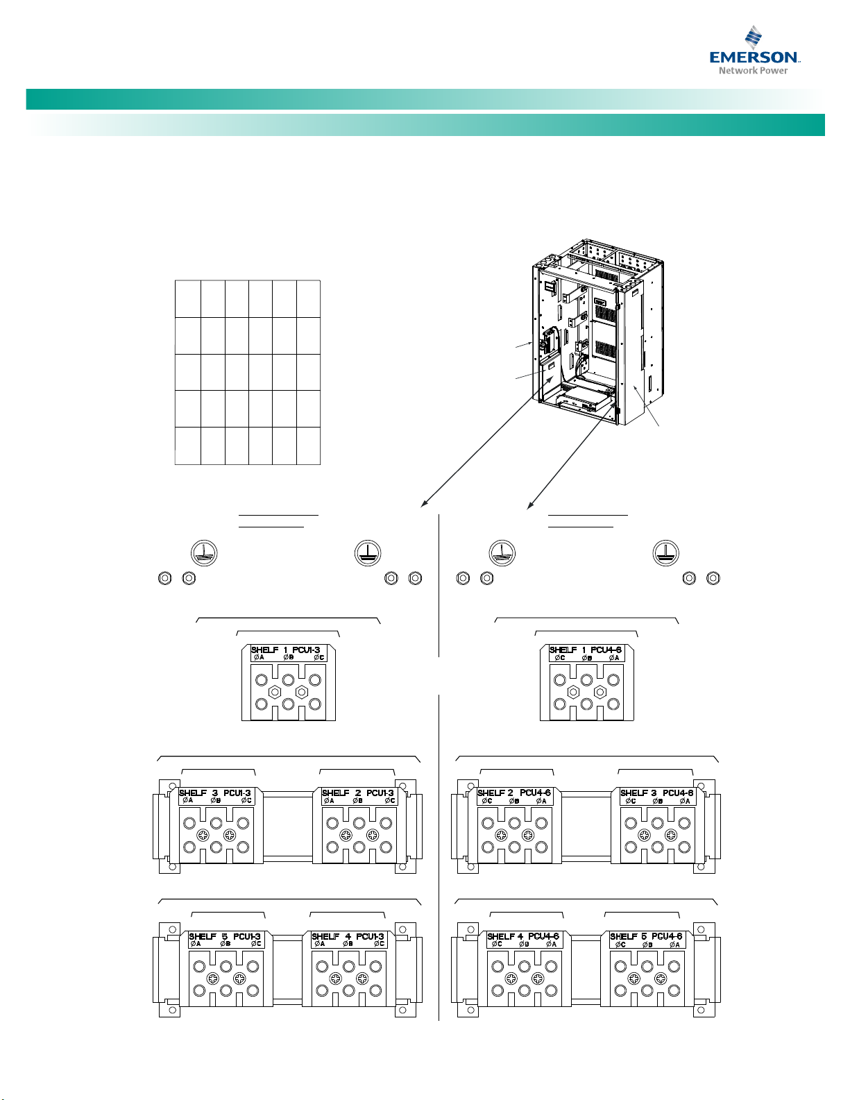
Make Nominal 400 Volts DC Input and Equipment Grounding Connections (if equipped)
Refer to Nominal 400 Volts DC Input and Equipment Grounding Connections (if equipped) in the MAKING ELECTRICAL CONNECTIONS section
of the Installation Instructions (IM582127000) for a complete procedure.
• 582127000 List 45, 46, 47
• 588705000 List 41
• 588705000 List 42
The available DC input options for this system are:
DC Input Termination Assemblies
• The system can be equipped with a DC input termination assembly which provides a separate DC input connection for each
converter position (582127000 List 45).
• The system can be equipped with a DC input termination assembly which provides a separate DC input connection for every
two (2) converter positions (582127000 List 46).
• The system can be equipped with a DC input termination assembly which provides a separate DC input connection for every
three (3) converter positions (582127000 List 47).
Direct DC Input Connections to the Module Mounting Shelves
• The system can be equipped with module mounting shelves that contain DC input terminal blocks which provide a separate DC
input connection for each converter position (588705000 List 41).
• The system can be equipped with module mounting shelves that contain DC input terminal blocks which provide a separate DC
input connection for every two (2) converter positions (588705000 List 42).
Spec. No: 582127000 Code: QS582127000
Model No: 721NPBB Issue AC, December 10, 2013
Page 27

NetSure™ -48V DC Power System
[19]
Note:
(4-Row Cabinet Shown,
Others Similar)
Front Door Removed in
Illustration for Clarity
DC INPUT CONNECTIONS,
1 FEED PER 1 CONVERTER
(582127000 LIST 45)
NOTE:
WIRING TO A FIELD INSTALLED
SHELF IS DONE AT THE REAR
OF THE SHELF.
DC Wireway
Cover
DC Wireway
Cover
DC Input
Connector Cover
Inside View
Left Side
Inside View
Right Side
GND GND
GND GND
Converter Module Mounting Slots
Shelf #1
Conv.1Conv.2Conv.3Conv.4Conv.5Conv.
6
Conv.1Conv.2Conv.3Conv.4Conv.5Conv.
6
Conv.1Conv.2Conv.3Conv.4Conv.5Conv.
6
Conv.1Conv.2Conv.3Conv.4Conv.5Conv.
6
Conv.1Conv.2Conv.3Conv.4Conv.5Conv.
6
Shelf #2
Shelf #3
Shelf #4
Shelf #5
Conv. 1
Conv. 2
Conv. 3
400VDC CONVERTER DC INPUT FEEDS
1 FEED PER 1 CONVERTER
SHELF 1
Conv. 1
Conv. 2
Conv. 3
Conv. 1
Conv. 2
Conv. 3
400VDC CONVERTER DC INPUT FEEDS
1 FEED PER 1 CONVERTER
SHELF 3
SHELF 2
+ - + - + -
+ - + - + -
+ - + - + -
Conv. 1
Conv. 2
Conv. 3
Conv. 1
Conv. 2
Conv. 3
400VDC CONVERTER DC INPUT FEEDS
1 FEED PER 1 CONVERTER
SHELF 5
SHELF 4
+ - + - + - + - + - + -
Conv. 4
Conv. 5
Conv. 6
400VDC CONVERTER DC INPUT FEEDS
1 FEED PER 1 CONVERTER
SHELF 1
Conv. 4
Conv. 5
Conv. 6
Conv. 4
Conv. 5
Conv. 6
400VDC CONVERTER DC INPUT FEEDS
1 FEED PER 1 CONVERTER
SHELF 2
SHELF 3
+ - + - + -
+ - + - + -
+ - + - + -
Conv. 4
Conv. 5
Conv. 6
Conv. 4
Conv. 5
Conv. 6
400VDC CONVERTER DC INPUT FEEDS
1 FEED PER 1 CONVERTER
SHELF 4
SHELF 5
+ - + - + - + - + - + -
CONV4
+ -
CONV5
+ -
CONV6
+ -
CONV4
+ -
CONV5
+ -
CONV6
+ -
CONV4
+ -
CONV5
+ -
CONV6
+ -
CONV4
+ -
CONV5
+ -
CONV6
+ -
CONV4
+ -
CONV5
+ -
CONV6
+ -
CONV1
+ -
CONV2
+ -
CONV3
+ -
CONV1
+ -
CONV2
+ -
CONV3
+ -
CONV1
+ -
CONV2
+ -
CONV3
+ -
CONV1
+ -
CONV2
+ -
CONV3
+ -
CONV1
+ -
CONV2
+ -
CONV3
+ -
Quick Start Guide, QS582127000 (Issue AC, December 10, 2013)
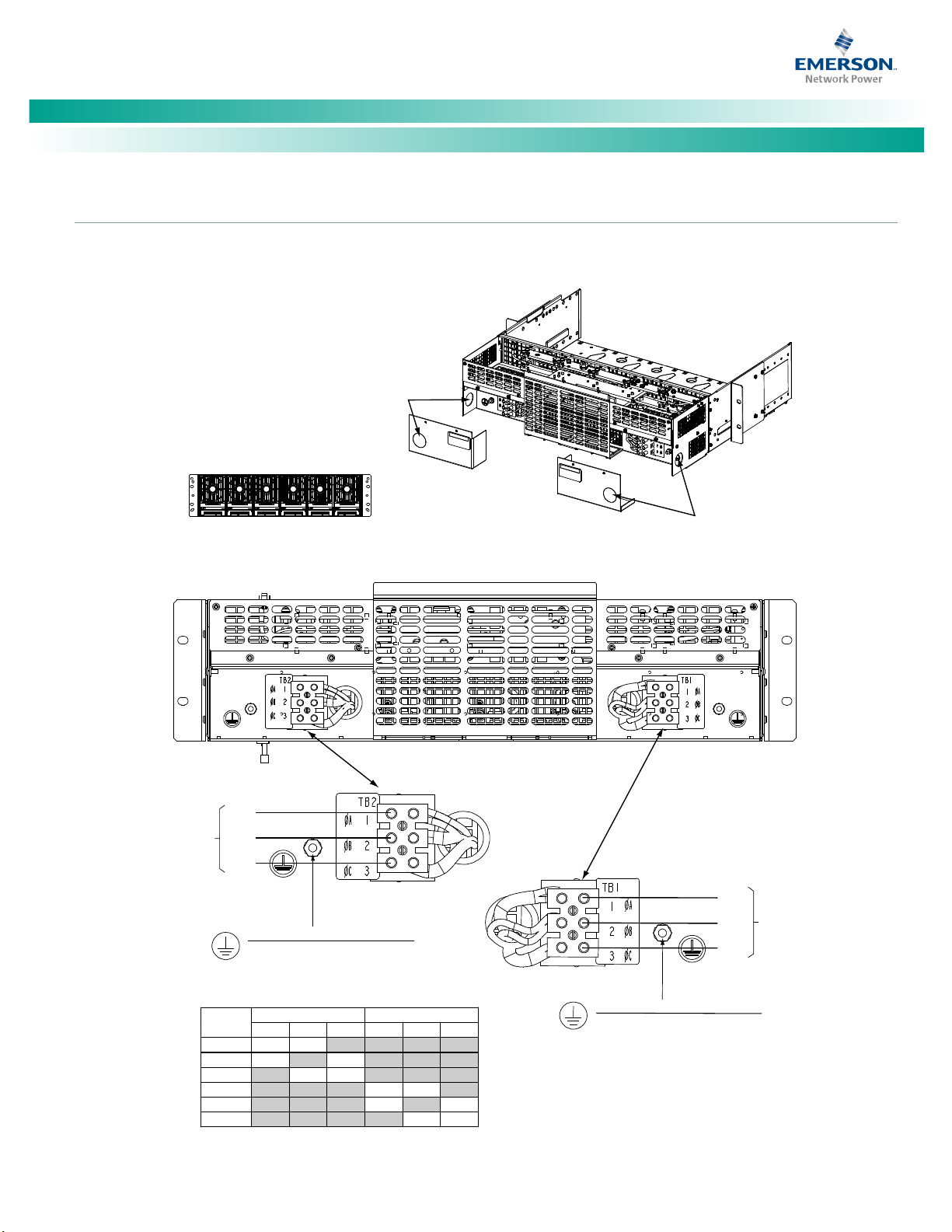
Connections to DC Input Termination Assemblies (582127000 List 45, 46, and 47)
Refer to Figure 15, Figure 16, or Figure 17.
Terminal blocks for a system with maximum possible converter shelves shown. Your system may have less terminal blocks then shown.
Figure 15. Nominal 400 Volts DC Input and Equipment Grounding Connections to DC Input Termination Assembly 582127000 List 45
(1 Feed per 1 Converter)
Spec. No: 582127000 Code: QS582127000
Model No: 721NPBB Issue AC, December 10, 2013
Page 28

[20]
(4-Row Cabinet Sh
o
wn
,
O
th
er
s
Si
mi
l
ar
)
F
r
on
t
Do
or
R
em
ov
e
d i
n
Illustration for Clarity
D
C I
N
PU
T C
O
NN
ECTIONS,
1 F
EE
D
PER 2 CONV
ER
T
ER
S
(
58
2
12
70
0
0 L
IS
T
46
)
In
sid
e Vi
ew
Lef
t Sid
e
Ins
ide V
iew
Ri
ght
Sid
e
NO
TE:
WIR
ING
TO A F
IEL
D IN
STA
LLED
SH
ELF
IS D
ONE
AT TH
E REA
R
OF
THE
SHEL
F.
G
ND GN
D
GN
D GN
D
D
C W
i
re
wa
y
C
o
ver
DC Wi
rew
ay
C
ove
r
DC In
put
Conne
c
to
r
Co
ve
r
Con
ver
ter M
odu
le M
oun
ting
Slo
ts
S
h
el
f #
1
Conv
.
1
C
o
nv
.
2
C
on
v.
3
Co
nv
.
4
C
o
nv
.
5
C
on
v.
6
Co
n
v.
1
C
o
nv
.
2
C
on
v.
3
Co
n
v.
4
C
o
nv
.
5
C
on
v.
6
C
on
v
.1C
o
nv
.2C
onv
.3C
onv
.4Conv.5C
on
v
.
6
Co
nv.
1
Con
v.
2
Con
v.3C
onv
.4C
onv.
5
Co
nv.
6
S
he
l
f #
2
S
hel
f #3
S
helf
#4
C
onv
. 1 Co
nv.
2 Conv. 3
400VD
C CON
VER
TER
DC I
NPUT
FEE
DS
1
FEED
PER
2 CO
NVERTERS
S
HELV
ES 1
AND
2
+ -
+ - + -
Co
nv. 1 Conv. 2
Conv. 3
400
VDC CON
VERTER D
C INPUT
FEEDS
1 FE
ED PER 2 C
ONVERT
ERS
SHEL
VES 3 AND 4
+ - + - + -
Conv. 4
Con
v. 5
Conv
. 6
40
0VD
C CONVERT
ER D
C IN
PUT
FEED
S
1 F
EED
PER 2
CON
VER
TERS
SHELVES 1
AND
2
+
- + - + -
Con
v. 4 Conv. 5
Conv. 6
400
VDC CONV
ERTER D
C INPUT F
EEDS
1 FEE
D PER 2 CO
NVERTERS
SHELVES 3 A
ND 4
+ - + -
+ -
CON
V 4
+ -
CONV 5
+
-
CO
NV 6
+ -
CONV 1
+
-
CO
NV 2
+ -
CON
V 3
+ -
CONV 4
+ -
C
ONV 5
+ -
CONV
6
+ -
CONV 1
+
-
CONV 2
+ -
CON
V 3
+ -
NetSure™ -48V DC Power System
Quick Start Guide, QS582127000 (Issue AC, December 10, 2013)
Figure 16. Nominal 400 Volts DC Input and Equipment Grounding Connections to DC Input Termination Assembly 582127000 List 46
(1 Feed per 2 Converters)
Spec. No: 582127000 Code: QS582127000
Model No: 721NPBB Issue AC, December 10, 2013
Page 29

NetSure™ -48V DC Power System
[21]
(4-Row Cabinet Shown,
Others Similar)
Front Door Removed in
Illustration for Clarity
DC INPUT CONNECTIONS,
1 FEED PER 3 CONVERTERS
(582127000 LIST 47)
Inside View
Left Side
Inside View
Right Side
NOTE:
WIRING TO A FIELD INSTALLED
SHELF IS DONE AT THE REAR
OF THE SHELF.
GND GND GND GND
DC Wireway
Cover
DC Wireway
Cover
DC Input
Connector Cover
400VDC CONVERTER DC INPUT FEEDS
1 FEED PER 3 CONVERTERS
SHELF 1: Conv. #1 - #3
400VDC CONVERTER DC INPUT FEEDS
1 FEED PER 3 CONVERTERS
SHELF 3: Conv. #1 - #3 SHELF 2: Conv. #1 - #3
Converter Module Mounting Slots
Shelf #1
Conv.1Conv.2Conv.3Conv.4Conv.5Conv.
6
Conv.1Conv.2Conv.3Conv.4Conv.5Conv.
6
Conv.1Conv.2Conv.3Conv.4Conv.5Conv.
6
Conv.1Conv.2Conv.3Conv.4Conv.5Conv.
6
Conv.1Conv.2Conv.3Conv.4Conv.5Conv.
6
Shelf #2
Shelf #3
Shelf #4
Shelf #5
+ -
+ - + -
400VDC CONVERTER DC INPUT FEEDS
1 FEED PER 3 CONVERTERS
SHELF 5: Conv. #1 - #3 SHELF 4: Conv. #1 - #3
+ - + -
400VDC CONVERTER DC INPUT FEEDS
1 FEED PER 3 CONVERTERS
SHELF 1: Conv. #4 - #6
400VDC CONVERTER DC INPUT FEEDS
1 FEED PER 3 CONVERTERS
SHELF 2: Conv. #4 - #6 SHELF 3: Conv. #4 - #6
+ -
+ - + -
400VDC CONVERTER DC INPUT FEEDS
1 FEED PER 3 CONVERTERS
SHELF 4: Conv. #4 - #6 SHELF 5: Conv. #4 - #6
+ - + -
SHELF 1 CONV4-6
SHELF 2 CONV4-6 SHELF 3 CONV4-6
SHELF 4 CONV4-6 SHELF 5 CONV4-6
SHELF 1 CONV1-3
SHELF 3 CONV1-3 SHELF 2 CONV1-3
SHELF 5 CONV1-3 SHELF 4 CONV1-3
Quick Start Guide, QS582127000 (Issue AC, December 10, 2013)
Figure 17. Nominal 400 Volts DC Input and Equipment Grounding Connections to DC Input Termination Assembly 582127000 List 47
(1 Feed per 3 Converters)
Spec. No: 582127000 Code: QS582127000
Model No: 721NPBB Issue AC, December 10, 2013
Page 30

NetSure™ -48V DC Power System
[22]
Hol
es
f
or
3/
4
"
Cond
ui
t
Fi
tt
i
ng
(I
npu
t)
Holes fo
r 3/
4"
Conduit Fi
tti
ng
(Input)
Rear View
Rear Vi
ew
Co
nve
rter Module Mount
ingSlot
s
(front view)
Con
v.1Co
nv.2C
onv.3Conv.
4
Conv
.5Co
nv.
6
Wire Size C
apacity: 10-20
AWG.
Recom
mended Torque: 10 in-
lbs.
FRAME GROUND CONNECTION
ONE 10-32 X 3/4" STUD
AND HARDWARE.
Recommended torque: 23 in-lbs.
FRAME GROUND CONNECTION
ONE 10-32 X 3/4" ST
UD
AND HARDWARE.
Recommended torque: 23 in-lbs.
+
-
+
-
400VDC
IN
Conve
rter
M
odu
le 4
Converter
Module 5
Converter
Mo
dule 6
Converter
Module 1
Converter
Module 2
Converter
Module 3
+
-
400VDC
IN
+
-
+
-
+
-
INDIVIDUAL 400VDC CONVERTER FEEDS
1
FEED PER CONVERTER
Quick Start Guide, QS582127000 (Issue AC, December 10, 2013)
Direct DC Input Connections to 588705000 List 41 Module Mounting Shelves
Refer to Figure 18.
Figure 18. Nominal 400 Volts DC Input and Equipment Grounding Connections to Module Mounting Shelf 588705000 List 41
(1 Feed per 1 Converter)
Spec. No: 582127000 Code: QS582127000
Model No: 721NPBB Issue AC, December 10, 2013
Page 31

NetSure™ -48V DC Power System
[23]
Ho
le
s
fo
r
3/
4"
Conduit Fitting
(I
npu
t)
Re
ar V
iew
C
on
v
e
r
te
r M
odu
le Mo
unt
ing
Slo
ts
(f
ron
t vie
w)
C
onv.
1
Con
v.
2
Co
nv.
3
C
onv.
4
C
o
nv
.
5
Co
nv.
6
CONVERTER 400
VDC INPUT FEEDS
1 F
EED PER 3 CONVERTERS
+
-
+
-
H
oles
for
3/4
"
Con
dui
t Fi
ttin
g
(Inp
ut)
Rear View
FR
AME GROUND
CONNECT
ION
ONE 10
-32 X 3/4" S
TUD
AND HAR
DWARE.
Rec
ommended tor
que: 23 in-l
bs.
F
R
AME
G
ROUNDCO
NNECTIO
N
O
NE10-32X3/4
"ST
U
D
A
N
DHARDWARE
.
R
e
commendedtorque
:
23in-lbs.
400VD
C IN
Feed
2
(Conv
erter
M
odules
4-6)
400VD
C IN
Fe
ed 1
(
Conver
ter
Modu
les
1-3)
Wi
re S
ize
Ca
pac
ity
: 6-14 A
WG.
Re
co
mm
end
ed Torq
ue: 18 i
n-lbs.
Quick Start Guide, QS582127000 (Issue AC, December 10, 2013)
Direct AC Input Connections to 588705000 List 42 Module Mounting Shelves
Refer to Figure 19.
Figure 19. Nominal 400 Volts DC Input and Equipment Grounding Connections to Module Mounting Shelf 588705000 List 42
(1 Feed per 2 Converters)
Spec. No: 582127000 Code: QS582127000
Model No: 721NPBB Issue AC, December 10, 2013
Page 32

NetSure™ -48V DC Power System
[24]
Optional SM-DU+ and
Shunt Interface Board
4-Row Cabinet Shown,
Others Similar
(Front Door Removed in
Illustration for Clarity)
System Interface
Circuit Card
IB2 (Main Bay Only)
(ACU+ Interface Board)
(located on inside side panel)
Optional EIB (Main Bay Only)
(ACU+ Extended Interface Board)
(located on inside side panel)
Quick Start Guide, QS582127000 (Issue AC, December 10, 2013)
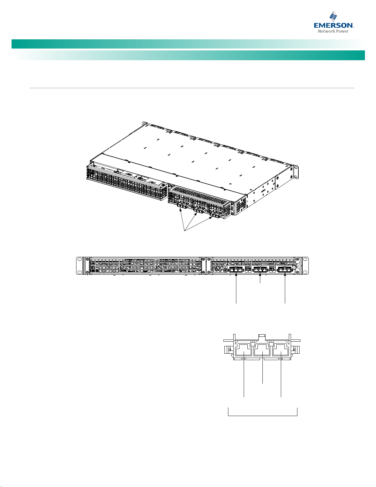
Make External Interface Connections
Refer to External Alarm, Reference, Monitoring, and Control Connections in the MAKING ELECTRICAL CONNECTIONS section of the
Installation Instructions (IM582127000) for complete procedures.
Circuit Card Locations
Refer to Figure 20.
Figure 20. Circuit Card Locations
Spec. No: 582127000 Code: QS582127000
Model No: 721NPBB Issue AC, December 10, 2013
Page 33

NetSure™ -48V DC Power System
[25]
Quick Start Guide, QS582127000 (Issue AC, December 10, 2013)
System Interface Circuit Card
The System Interface Circuit Card provides connections for the following.
Refer to Figure 21.
• RS-485 (used for communication with SM modules)
• RS-232 (used for communication with a DPU)
• External Battery Monitoring (circuit card installed in Main Bay only)
• External System FA Signal (circuit card installed in Main Bay only)
• External Battery FA Signal (circuit card installed in Main Bay only)
• Battery Tray FA Signal
• Bay Voltage Monitoring Test Points
• Bay Load Shunt Monitoring Test Points
Spec. No: 582127000 Code: QS582127000
Model No: 721NPBB Issue AC, December 10, 2013
Page 34

NetSure™ -48V DC Power System
[26]
g
Card in Main Bay
in 1st Supplemental Bay
in 2nd Supplemental Bay
Quick Start Guide, QS582127000 (Issue AC, December 10, 2013)
Figure 21. System Interface Circuit Card Connections
J1
J2
TB2
RS485 Connection
TB2 1A: RS485+
TB2 2A: RS485-
RS232 Connection
TB2 1B: CGND
TB2 2B: TXD232
TB2 3B:RXD232
TB2 3A: Internally
used by system.
1B 2B 3B
TB2
1A 2 A 3A
J8
TB1
1
5
J3
J4
J10
J5
J1, J2, J3, J4
Distribution Panels FA Inputs
J8 (Main Bay Only)
Selects to power Controller
from “Battery Power” or not.
No
Battery
1
2
3
Shorting Jumper
J10 (Main Bay Only)
Battery Monitoring External / Internal
(see TB1-4 and TB1-5 for
external monitoring points)
External Internal
1
2
3
Pwr
Battery
Pwr
J8
7
8
9
7
8
9
TP1 TP2 TP3 TP4
TB1-1: Battery Tray FA
TB1-2: External Battery FA
TB1-4: External Battery Monitoring (-)
TB1-5: External Battery Monitoring (+)
System Interface
Spec. No: 582127000 Code: QS582127000
Model No: 721NPBB Issue AC, December 10, 2013
TB1-3: External System FA
TB1
TB1-2, TB1-3, TB1-4, TB1-5 Main Bay Only.
Wire Size Capacity: 22-12 AWG.
Recommended Torque: 3.0 in-lbs.
FA Signals: System voltage applied to the
terminal turns in an alarm.
System Interface Card
TP1 (+) and TP2 (-)
Bay Voltage
Monitoring
TP3 (+) and TP4 (-)
Bay Load
Shunt Monitoring
System Interface Card
Shorting Jumper
J5
CAN
J10
System Interface
Card in Last Bay
CAN termination plu
must be installed.
Page 35

NetSure™ -48V DC Power System
[27]
Digital Inputs
Programmable Relay Outputs
Note:
Quick Start Guide, QS582127000 (Issue AC, December 10, 2013)
IB2 (ACU+ Interface Board) Connections (if required) (Main Bay Only)
The IB2 (ACU+ Interface Board) provides connection points for
digital inputs, programmable relay outputs, and temperature
probes. The IB2 interface board is mounted inside the distribution
cabinet. Refer to Figure 20.
Digital Inputs and Programmable Relay Outputs
Digital input and relay output leads are connected to screw-type
terminal blocks located on the IB2. Recommended torque for
these connections is 2.2 in-lbs. Refer to Figure 22 for terminal
locations. Refer to Table 1and Table 2 for pin-out information.
Connect up to eight (8) digital inputs to the IB2. Note that you
must supply both paths for the digital input (either a positive or
negative signal and the opposite polarity return path). Observe
proper polarity. Refer to Figure 22 for terminal locations and Table
1 for pin-out information.
The digital inputs can be programmed to provide an alarm when
the signal is applied (HIGH) or removed (LOW). Refer to the ACU+
Instructions (UM1M820BNA or UM1M820DNA400) for
programming information.
Digital Input Ratings: Refer to the following.
a. Maximum Voltage Rating: 60V DC.
a. Active High: > 19V DC.
b. Active Low: < 1V DC.
The digital inputs may be preprogrammed for specific functions.
Refer to the configuration drawing (C-drawing) supplied with your
system for your system’s specific configuration.
The IB2 provides eight (8) programmable alarm relays with dry
Form-C contacts. Connect up to eight (8) relay outputs to the IB2.
Refer to Figure 22 for terminal locations and Table 2for pin-out
information.
Refer to the ACU+ Instructions (UM1M820BNA or
UM1M820DNA400) for programming information.
Relay Ratings: Refer to the following.
The relays may be preprogrammed for specific functions. Refer to
the configuration drawing (C-drawing) supplied with your system
for your system’s specific configuration.
Temperature Probes
Each temperature probe consists of two pieces that plug
together to make a complete probe. See SAG582127000 for
part numbers and descriptions.
Temperature probes are connected to the IB2 (ACU+ Interface
Board) and/or optional EIB (ACU+ Extended Interface Board)
mounted inside the distribution cabinet. See Figure 22 and Figure
24.
Up to two (2) temperature probes can be connected to the IB2. Up
to two (2) additional temperature probes can be connected to the
optional EIB. Any combination of the four (4) temperature probes
can be programmed to monitor ambient temperature and/or
battery temperature. A temperature probe set to monitor battery
temperature can also be used for the rectifier battery charge
temperature compensation feature, or the battery charge
temperature compensation feature can be programmed to use the
average or highest value of all battery temperature probes. The
battery charge temperature compensation feature allows the
controller to automatically increase or decrease the output voltage
of the system to maintain battery float current as battery
temperature decreases or increases, respectively. Battery life can
be extended when an optimum charge voltage to the battery with
respect to temperature is maintained. A temperature probe set to
monitor battery temperature can also be used for the BTRM
(Battery Thermal Runaway Management) feature. The BTRM
feature lowers output voltage when a high temperature condition
exists to control against battery thermal runaway.
The temperature sensor end of the probe contains a tab with a
5/16” clearance hole for mounting.
A temperature probe programmed to monitor battery
temperature should be mounted on the negative post of a battery
cell to sense battery temperature. A temperature probe used for
battery charge temperature compensation and/or BTRM (Battery
Thermal Runaway Management) should also be mounted on the
negative post of a battery cell. A temperature probe programmed
to monitor ambient temperature should be mounted in a
convenient location, away from direct sources of heat or cold.
a. 1A Steady State @ 30V DC.
b. 3A Peak @ 30V DC.
Spec. No: 582127000 Code: QS582127000
Model No: 721NPBB Issue AC, December 10, 2013
Page 36

[28]
* The ACU+ relay
assigned to “Critic
al Summary” alarm (
relay 1 by default
)
will oper
ate in the “Fail Safe
Mode”. “Fail Safe Mode” mean
s Relay 1 is
de-energi
zed during an alarm c
ondition, opening the
contacts between the
C and NO terminal
s, and closing the contacts betwee
n the C and NC termi
nals.
The ACU+’s rema
ining seven (7) relay
s energize during an alarm condition, c
losing
the contacts b
etween the C and NO terminals, and op
ening the contacts between
the C a
nd NC terminals.
Not all I/O points are a
vailable for customer connection (some are u
sed for factory
system connections).
J3-J9:
Wire Size Capacity: 16-26 AWG.
Recommended Torque: 2.2 in-lbs.
MA4C5U31
IB2
D
I1
-
DI
1
+
DI2-
DI2+
D
I3
-
DI3+
J3
J4
J5
J
6
J7
J8
J
9
DI4-
DI4+
DI5-
DI5+
DI6-
DI6+
DI7-
DI
7+
DI8-
DI8+
DO1_NC
DO2_NC
DO1
_COM
DO2_
COM
DO1_NO
DO2_
NO
DO3_NC
D
O4_N
C
DO3_COM
DO4_CO
M
DO3_
NO
DO
4_N
O
DO5_NC
DO6_
NC
DO5_C
OM
DO6_COM
DO5_NO
DO6_NO
D
O7_NC
DO8_NC
DO7
_COM
DO8_COM
DO
7_NO
DO8_NO
J11 1
J11 2
J11 3
J12 1
J12 2
J12 3
2
4
3
1
J2
6 5 4 3 2 1 6 5 4 3 2 1 6 5 4 3 2 1 6 5 4 3 2 1 6 5 4 3 2 1 6 5 4 3 2 1 6 5 4 3 2 1
STUPTUOYALER
STUPNILATIGID
Sc
hem
at
ic
Di
ag
ra
m of
I
B2 B
oa
rd
IB2 TEMP
PR
OB
E
1
IB2 TEMP
P
RO
BE 2
-
J12
*
RELAY
SW1
7
J2
J11
5 3 1
Relay Output Terminal Blocks
Digital Input Terminal Blocks
J9 J8 J7
J6
J5 J4
J3
8 6 4
2
8 7 6 5 4 3
2 1
+
IB2 Board (Top View)
NO C NC
NO C NC
NO C NC
NO C NC
NO C NC
NO C NC
NO C NC
NO C NC
5 3 1
46 2
5
3
1
46 2
5 3 1
46 2
5 3 1
46 2
5 3 1
46 2
5 3 1
46 2
5 3 1
46 2
Connector
to ACU+
IB2 TEMP
PROBRE 1
IB2 TEMP
PROBE 2
IB2 Board Assembly
NetSure™ -48V DC Power System
Quick Start Guide, QS582127000 (Issue AC, December 10, 2013)
Figure 22. IB2 (Interface Board) Connections
Spec. No: 582127000 Code: QS582127000
Model No: 721NPBB Issue AC, December 10, 2013
Page 37

NetSure™ -48V DC Power System
[29]
Note:
Quick Start Guide, QS582127000 (Issue AC, December 10, 2013)
Table 1. Programmable Digital Inputs – IB2
Programmable
Digital Input
1
2
3
4
5
6
7
8
-- J5-5
-- J5-6
IB2
Pin No.
J3-2 +
J3-1 –
J3-4 +
J3-3 –
J3-6 +
J3-5 –
J4-2 +
J4-1 –
J4-4 +
J4-3 –
J4-6 +
J4-5 –
J5-2 +
J5-1 –
J5-4 +
J5-3 – -48VDC
The digital inputs may be
preprogrammed for specific
functions and have factory
wiring connected. Refer to
the configuration drawing
(C-drawing) supplied with
your system for your
system’s specific
configuration.
Factory
Wiring
(to customer
ESTOP switch)
not used not used not used
Default Digital
Input Function
The digital inputs may be
preprogrammed for specific
functions. Refer to the
configuration drawing (Cdrawing) supplied with your
system for your system’s
specific configuration.
ESTOP
Customer Defined
Digital Input Function
-48V is factory wired to the Digital Input #8 (-) terminal for your convenience and function predefined for ESTOP. Customerfurnished system ground applied to terminal Digital Input #8 (+) activates the ESTOP function. The ESTOP function shuts down and
locks out the rectifiers or 400V DC input converters, opens the LVD’s, and shuts down the optional -48V to +24V DC converters.
When the ESTOP signal is removed, LVD’s close (if battery present) and -48V to +24V DC converters restart. To restart the rectifiers
or 400V DC input converters; turn input power to the rectifiers/converters OFF, wait 30 seconds or more (until the LEDs on the
module extinguish), then turn input power to the rectifiers/converters ON. Rectifiers/converters can also be restarted from the ACU+
LCD or WEB Interface menu (via the Rectifier Reset or Converter Reset command, found in the Manual menu in the LCD menus or
under the Rectifier or Converter Control Tab in the WEB Interface).
Spec. No: 582127000 Code: QS582127000
Model No: 721NPBB Issue AC, December 10, 2013
Page 38

NetSure™ -48V DC Power System
[30]
Note:
Quick Start Guide, QS582127000 (Issue AC, December 10, 2013)
Table 2. Programmable Relay Outputs – IB2
Programmable
Relay Output
NO J6-5
1
2
3
4
5
6
7
8
COM J6-3
NC J6-1
NO J6-6
NC
NO J7-5
NC J7-1
NO J7-6
NC J7-2
NO J8-5
NC J8-1
NO J8-6
NC J8-2
NO J9-5
NC J9-1
NO J9-6
NC
The ACU+ relay assigned to “Critical Summary” alarm (relay 1 by default) will operate in the “Fail Safe Mode”.
“Fail Safe Mode” means Relay 1 is de-energized during an alarm condition, opening the contacts between the C
and NO terminals, and closing the contacts between the C and NC terminals.
The ACU+ remaining 7 relays energize during an alarm condition, closing the contacts between the C and NO
terminals, and opening the contacts between the C and NC terminals.
IB2
Pin No.
J6-2
J8-4
J9-2
Alarms Assigned to this Relay
(Default)
The relays may be preprogrammed
for specific functions. Refer to the
configuration drawing (C-drawing)
supplied with your system for your
system’s specific configuration.
Alarms Assigned to this Relay
(Custom)
COM J6-4
COM J7-3
COM J7-4
COM J8-3
COM
COM J9-3
COM J9-4
Spec. No: 582127000 Code: QS582127000
Model No: 721NPBB Issue AC, December 10, 2013
Page 39

NetSure™ -48V DC Power System
[31]
Current Inputs
Number of
Battery Shunts
Number of
Load Shunts
Connect to EIB Shunt
Inputs as Follows
Quick Start Guide, QS582127000 (Issue AC, December 10, 2013)
Optional EIB (ACU+ Extended Interface Board) Connections (if required) (Main Bay Only)
The optional EIB (ACU+ Extended Interface Board) provides additional connection points for voltage and current inputs, programmable
relay outputs, and temperature probes. The EIB extended interface board is mounted inside the distribution cabinet. Refer to Figure 20.
Current Inputs, Voltage Inputs, and Programmable Relay Outputs
Current input, voltage input, and relay output leads are connected to screw-type terminal blocks located on the optional EIB.
Recommended torque for these connections is 2.2 in-lbs. Refer to Figure 24 for terminal locations. Refer to Table 4, Table 5, and Table 6
for pin-out information.
Connect up to three (3) shunt inputs to the EIB. Observe proper polarity. Refer to Figure 24 for terminal locations and Table 4 for pin-out
information. Refer to Table 3 to determine what shunt input to connect to on the EIB board.
Refer to the ACU+ Instructions (UM1M820BNA or UM1M820DNA400) and program the shunt input parameters found in the EIB menu.
Table 3. Shunt Inputs to EIB Extended Interface Board
1 0
2 0
3 0
0 1
0 2
0 3
1 1
2 1
1 2
Shunt 1 – Battery 1
Shunt 2 – none
Shunt 3 – none
Shunt 1 – Battery 1
Shunt 2 – Battery 2
Shunt 3 – none
Shunt 1 – Battery 1
Shunt 2 – Battery 2
Shunt 3 – Battery 3
Shunt 1 – none
Shunt 2 – none
Shunt 3 – Load 1
Shunt 1 – none
Shunt 2 – Load 2
Shunt 3 – Load 1
Shunt 1 – Load 3
Shunt 2 – Load 2
Shunt 3 – Load 1
Shunt 1 – Battery 1
Shunt 2 – none
Shunt 3 – Load 1
Shunt 1 – Battery 1
Shunt 2 – Battery 2
Shunt 3 – Load 1
Shunt 1 – Battery 1
Shunt 2 – Load 2
Shunt 3 – Load 1
Spec. No: 582127000 Code: QS582127000
Model No: 721NPBB Issue AC, December 10, 2013
Page 40

NetSure™ -48V DC Power System
[32]
Voltage Inputs for Battery Block and Battery Midpoint Monitoring
Battery Block Monitoring
Midpoint Monitoring
Quick Start Guide, QS582127000 (Issue AC, December 10, 2013)
The ACU+ can monitor battery blocks (12V blocks) or midpoint battery voltage of battery strings connected to the EIB. The EIB provides a
total of eight (8) DC voltage inputs for these connections. An alarm is issued when either battery block voltage or battery midpoint
voltage is abnormal. Refer to Figure 24 for terminal locations and Table 5 for pin-out information.
Refer to Figure 23 for connection details. Refer to the ACU+ Instructions (UM1M820BNA or UM1M820DNA400) and program the
following parameters found in the EIB menu.
•
Voltage Type: Set to “48 (Block 4)”. This selects the EIB to monitor up to two (2) 48V battery strings with four (4) 12V blocks
per string
BlockVDiff(12V): This menu item appears if “48 (Block 4)” is selected above. Set to the alarm threshold for battery block
monitoring per site requirements. The ACU+ issues an alarm when any block voltage of any battery string has an abnormal
value. The alarm is issued when the difference between any block voltage and a reference voltage is greater than the value of
the block voltage difference setting.
Block In-Use: Set to the number of 12V battery blocks being used.
•
Voltage Type: Set to “Midpoint”. This selects the EIB to monitor the midpoint voltage of up to eight (8) battery strings.
BlockVDiff(Mid): This menu item appears if “Midpoint” is selected above. Set to the alarm threshold for battery midpoint
monitoring per site requirements. The ACU+ issues an alarm when any battery midpoint voltage of any battery string has an
abnormal value. The alarm is issued when the difference between any battery midpoint voltage and a reference voltage is
greater than the value of the block voltage difference setting.
Block In-Use: Set to number of 12V battery blocks being used.
Spec. No: 582127000 Code: QS582127000
Model No: 721NPBB Issue AC, December 10, 2013
Page 41

NetSure™ -48V DC Power System
[33]
Battery Midpoint Monitoring
Battery Block Monitoring
Battery
String 1
to
DCV1
(J6-1)
to
DCV2
(J6-2)
to
DCV3
(J6-3)
to
DCV4
(J6-4)
to
DCV5
(J6-5)
to
DCV6
(J6-6)
to
DCV7
(J7-1)
to
DCV8
(J7-3)
Battery
String 2
Battery
String 3
EIB Board Voltage Inputs
Battery
String 4
Battery
String 5
Battery
String 6
Battery
String 7
Battery
String 8
Rectifiers
Return
-48V
Load Shunt
Load
Battery
String 1
to
DCV1
(J6-1)
to
DCV2
(J6-2)
to
DCV3
(J6-3)
to
DCV4
(J6-4)
to
DCV5
(J6-5)
to
DCV6
(J6-6)
to
DCV7
(J7-1)
to
DCV8
(J7-3)
Battery
String 2
EIB Board Voltage Inputs
Rectifiers
+
12V
-
+
12V
-
+
12V
-
+
12V
-
+
12V
-
+
12V
-
+
12V
-
+
12V
-
+
12V
-
+
12V
-
+
12V
-
+
12V
-
+
12V
-
+
12V
-
+
12V
-
+
12V
-
+
12V
-
+
12V
-
+
12V
-
+
12V
-
+
12V
-
+
12V
-
+
12V
-
+
12V
-
+
12V
-
+
12V
-
+
12V
-
+
12V
-
+
12V
-
+
12V
-
+
12V
-
+
12V
-
+
12V
-
+
12V
-
+
12V
-
+
12V
-
+
12V
-
+
12V
-
+
12V
-
+
12V
-
Return
-48V
Load Shunt
Load
Quick Start Guide, QS582127000 (Issue AC, December 10, 2013)
Figure 23. Sample Battery Block or Battery Midpoint Monitoring Connections
Spec. No: 582127000 Code: QS582127000
Model No: 721NPBB Issue AC, December 10, 2013
Page 42

NetSure™ -48V DC Power System
[34]
Programmable Relay Outputs
Quick Start Guide, QS582127000 (Issue AC, December 10, 2013)
The EIB provides five (5) programmable alarm relays with dry Form-C contacts. Connect up to five (5) relay outputs to the IB2. Refer to
Figure 24 for terminal locations and Table 6 for pin-out information.
Refer to the ACU+ Instructions (UM1M820BNA or UM1M820DNA400) for programming information.
Relay Ratings: Refer to the following.
a. 1A Steady State @ 30V DC.
b. 3A Peak @ 30V DC.
The relays may be preprogrammed for specific functions. Refer to the configuration drawing (C-drawing) supplied with your system for
your system’s specific configuration.
Temperature Probes
Temperature probes can be connected to the optional EIB (ACU+ Extended Interface Board) mounted inside the distribution cabinet.
Refer to “Temperature Probes” on page 27.
Spec. No: 582127000 Code: QS582127000
Model No: 721NPBB Issue AC, December 10, 2013
Page 43

NetSure™ -48V DC Power System
[35]
MA455U41
EIB
SH1-
SH1+
SH2-
SH2+
SH3-
SH3+
J5
J6
J7
J8 J9
DCV1
DCV2
DCV3
DCV4
DCV5
DCV6
DCV7
DO5_NC
DCV8
DO5_COM
DO1_NC
DO2_NC
DO1_COM
DO2_COM
DO1_NO
DO2_NO
DO3_NC
DO4_NC
DO3_COM
DO4_COM
DO3_NO
DO4_NO
J3 1
J
3 2
J3 3
J4 1
J4 2
J4 3
2 4
3 1
J2
DO5_NO
1
2 3 4
5
6 1
2 3
4 5 6
1
2 3
4 5 6
1
2 3
4 5
6 1
2 3
4 5
6
SHUNT
INPUTS
V
O
LTA
GE
INPUTS
RELAY OUTPUTS
EIB T
EMP
P
ROB
E 2
TEMP
PR
O
BE 1
Schematic Diagram of EIB Board
J5-J9
Wire Size Capacity: 16-26 AWG.
Recommended Torque: 2.2 in-lbs.
EIB Board
J5 J6 J7 J8 J9
2
4
6
31 5
2
4
6
31 5
2
4
6
31 5
2
4
6
31 5
2
4
6
31 5
Quick Start Guide, QS582127000 (Issue AC, December 10, 2013)
Figure 24. EIB (Extended Interface Board) Connections
Spec. No: 582127000 Code: QS582127000
Model No: 721NPBB Issue AC, December 10, 2013
Page 44

NetSure™ -48V DC Power System
[36]
Shunt Input
EIB
Pin No.
Factory
Wiring
Default
Function
Customer
Defined Function
Voltage Input
EIB
Pin No.
Default
Function
Quick Start Guide, QS582127000 (Issue AC, December 10, 2013)
Table 4. Shunt Inputs – EIB
Sh1
Sh2
Sh3
Table 5. Voltage Inputs – EIB
J5-2 + --
J5-1 – --
J5-4 + --
J5-3 – --
J5-6 + --
J5-5 – --
1 J6-1
2
3
4
5 J6-5
J6-2
J6-3
J6-4
none
none
none
Battery
Block
Monitoring
6 J6-6
7 J7-1
8
Spec. No: 582127000 Code: QS582127000
Model No: 721NPBB Issue AC, December 10, 2013
J7-3
Page 45

NetSure™ -48V DC Power System
[37]
Programmable Relay
Output
EIB
Pin No.
Alarms Assigned to this Relay
(Default)
Alarms Assigned to this Relay
(Custom)
Note:
Quick Start Guide, QS582127000 (Issue AC, December 10, 2013)
Table 6. Programmable Relay Outputs – EIB
NO J8-5
9
NC J8-1
NO J8-6
10
NC J8-2
NO J9-5
11
NC J9-1
NO J9-6
12
NC J9-2
NO J7-6
13
NC J7-2
J8-4
The relays may be preprogrammed
for specific functions. Refer to the
configuration drawing (C-drawing)
supplied with your system for your
system’s specific configuration.
J9-4
J7-4
COM J8-3
COM
COM J9-3
COM
COM
The relays energize during an alarm condition, closing the contacts between the C and NO terminals, and opening the
contacts between the C and NC terminals.
Spec. No: 582127000 Code: QS582127000
Model No: 721NPBB Issue AC, December 10, 2013
Page 46

NetSure™ -48V DC Power System
[38]
Current Inputs:
Note:
Quick Start Guide, QS582127000 (Issue AC, December 10, 2013)
Optional SM-DU+ and Shunt Interface Board
The optional SM-DU+ and Shunt Interface Board provides connections for up to twenty-five (25) shunt inputs. Inputs are factory
connected to any distribution positions/devices containing shunts. Refer to Figure 25.
PROCEDURE
inputs may be factory connected, depending on distribution devices installed. Refer to the ACU+ Instructions (UM1M820BNA or
UM1M820DNA400) for programming information for the unused inputs.
The shunt needs to be installed in the hot (-48V) bus. Connect the plus side of the shunt to the positive shunt input on the SM-DU+.
Connect up to twenty-five (25) shunt inputs to the Shunt Interface Board. Observe proper polarity. Note that some
Connect the negative side of the shunt to the negative shunt input on the SM-DU+.
Spec. No: 582127000 Code: QS582127000
Model No: 721NPBB Issue AC, December 10, 2013
Page 47

NetSure™ -48V DC Power System
[39]
TB1 - TB2
Wire Size Capacity: 16-26 AWG.
Recommended Torque: 2.2 in-lbs.
Shunt Interface Board
SMDU+
2
1
J3
1
2
J1
SHUNT
INPUTS
541127
SHUNT
1
2
3
4
5
6
7
8
9
10
11
12
13
14
15
16
17
18
19
20
21
22
23
24
25
26
J1
1
2
3
4
5
6
7
8
9
10
11
12
13
14
15
16
17
18
19
20
21
22
23
24
25
26
J2
SHUNT25+
SHUNT25SHUNT24+
SHUNT24SHUNT23+
SHUNT23SHUNT22+
SHUNT22SHUNT21+
SHUNT21SHUNT20+
SHUNT20SHUNT19+
SHUNT19SHUNT18+
SHUNT18SHUNT17+
SHUNT17SHUNT16+
SHUNT16SHUNT15+
SHUNT15SHUNT14+
SHUNT14-
TB2
25A
25B
24A
24B
23A
23B
22A
22B
21A
21B
20A
20B
19A
19B
18A
18B
17A
17B
16A
16B
15A
15B
14A
14B
SHUNT12+
SHUNT12-
SHUNT13+
SHUNT13-
SHUNT11+
SHUNT11SHUNT10+
SHUNT10SHUNT9+
SHUNT9SHUNT8+
SHUNT8SHUNT7+
SHUNT7SHUNT6+
SHUNT6SHUNT5+
SHUNT5SHUNT4+
SHUNT4SHUNT3+
SHUNT3SHUNT2+
SHUNT2SHUNT1+
SHUNT1-
TB1
12A
12B
13A
13B
11A
11B
10A
10B
9A
9B
8A
8B
7A
7B
6A
6B
5A
5B
4A
4B
3A
3B
2A
2B
1A
1B
3
INTERFAC E
1A
1B
TB1 TB2
J2J1
Schematic Diagram of SM-DU+ and Shunt Interface Board
SM-DU+ and Shunt
Interface Board
-
+
Quick Start Guide, QS582127000 (Issue AC, December 10, 2013)
Figure 25. SM-DU+ and Shunt Interface Board Connections
Spec. No: 582127000 Code: QS582127000
Model No: 721NPBB Issue AC, December 10, 2013
Page 48

NetSure™ -48V DC Power System
[40]
ACU+ CAN
Port (RJ-45)
SM-Temp Module
CAN Port
Pin Number
Pin Number
Function
Quick Start Guide, QS582127000 (Issue AC, December 10, 2013)
Connecting a Device or System to the ACU+ CAN Bus
A supporting device or system may be connected to the ACU+ CAN Port. Refer to Figure 21 for location. Refer to Table 7 for pin-outs.
Refer also to the external device’s or system’s instruction manual.
General Procedure
1. Remove the CAN termination plug from the bottom CAN connector on the System Interface circuit card of the last bay (see
Figure 21 for location). Connect the device or system to the bottom CAN connector on the System Interface circuit card of the
last bay. Refer to Table 7 for pin-outs. Refer also to the external device’s or system’s instruction manual.
Optional SM-Temp Module Procedure
The analog output of the SM-Temp Module may be connected to an ACU+ temperature port input. In lieu of connecting the analog
output of the SM-TEMP module to an ACU+ temperature port input, the SM-TEMP module can simply be connected at the end of the
ACU+ CAN bus (requires ACU+ version 3.02 or later). Refer to the SM-Temp Module Instructions (UM547490) for details.
CONNECTING THE SM-TEMP MODULE TO THE ACU+ CAN BUS
1. Remove the CAN termination plug from the bottom CAN connector on the System Interface circuit card of the last bay.
Connect the SM-Temp Module CAN bus to the bottom CAN connector on the System Interface circuit card of the last bay. Refer
to Table 7 for pin-outs. Ensure the last SM-Temp Module (or if only one) has a CAN termination strap as shown in the SM-Temp
Module Instructions (UM547490).
Table 7. CAN Connections
1 CAN L TB1-5 (CAN L)
2 CAN H TB1-3 (CAN H)
3 -- --
4 -- --
5 -- --
6 -- --
7 -- --
8 -- --
Spec. No: 582127000 Code: QS582127000
Model No: 721NPBB Issue AC, December 10, 2013
Page 49

NetSure™ -48V DC Power System
[41]
Note:
Note:
E
Quick Start Guide, QS582127000 (Issue AC, December 10, 2013)
Make ACU+ Controller Ethernet Connection (if required)
If the Web Interface will be used, connect to the Ethernet port on the front of the Controller. Location is shown in Figure 26.
Refer to External Alarm, Reference, Monitoring, and Control Connections in the MAKING ELECTRICAL CONNECTIONS section of the
Installation Instructions (IM582127000) for Ethernet connection details.
You can access the Web pages of the power system locally by using a "crossover" or “straight” cable connected directly between your PC
and the ACU+.
Figure 26. ACU+ Ethernet Port
t (RJ-
the
rne
t Por
45)
ESC ENT
Make Bay-to-Bay Communications Cable Connections
Refer to Bay-to-Bay Communications Cable Connections in the MAKING ELECTRICAL CONNECTIONS section of the Installation Instructions
(IM582127000) for a complete procedure.
The bay’s are interconnected using standard Cat5 communications cables. Supplemental bays are provided with a 25’ cable. Refer to
Figure 27 for a bay-to-bay cable diagram.
Maximum combined length of the Cat5 communications cables is 328’ (100m) per industry standards.
Installing Bay-to-Bay Busbars (582127000 List 1 with List 2 / List 3)
Refer to Installing Bay-to-Bay Busbars (582127000 List 1 with List / List 3) in the MAKING ELECTRICAL CONNECTIONS section of the
Installation Instructions (IM582127000) for a complete procedure.
When 582127000 List 3 and/or List 2 is ordered, bay-to-bay busbars and hardware are provided for system power connections between
distribution cabinets. Interconnect per Figure 28.
Spec. No: 582127000 Code: QS582127000
Model No: 721NPBB Issue AC, December 10, 2013
Page 50

NetSure™ -48V DC Power System
[42]
Use
standard C
at5
communications cables.
1. Rem
ove terminat
ing p
lug from bottom connector on the Syst
em Interface Circuit Card installed in the Main Bay
and
place in bottom connector on the System Interface Circuit Card in the last bay.
2. Connect the bottom connector on the System Interface Circuit Card installed in the Main Bay
to the top connector on the System Interface Cir
cuit Card installed in the 1st Supplemental Bay.
3. Connect the bottom connector on the System Interface Circuit Card installed in the 1st Supplemental Bay
to the top connector on the System Interface Ci
rcuit Card installed in the 2nd Supplemental Bay.
Main Bay 1st
Supple
ment
al
Bay
2nd
Supplemental
Bay
Termination
Plug
System Interface
Card in Main Bay
System Interface Card
in 1st Supplemental Bay
System Interface Card
in 2nd Supplemental Bay
System Interface Card
in Last Bay
Front doors remove in
illustration for clarity only.
Quick Start Guide, QS582127000 (Issue AC, December 10, 2013)
Figure 27. Bay-to-Bay Communications Cable Connections
Spec. No: 582127000 Code: QS582127000
Model No: 721NPBB Issue AC, December 10, 2013
Page 51

NetSure™ -48V DC Power System
[43]
1. Remove center right (4-Row Cab.)
or lower right (3-Row Cab.) Rear
Access Cover from distribution
cabinets (note that the complete
rear cover is removed in the
illustration for clarity only).
2. Attach Return Angle Brackets.
3. Attach -48V Angle Brackets.
4. Attach flat Return Interbay Busbars.
5. Attach flat -48V Interbay Busbars.
6. Attach Insulator Standoffs onto
Return Interbay Busbars.
Return Angle Bracket
Secure 2 places
with (in order listed)
3/8-16 x 1-1/4” Bo
lt,
3/8” Belleville Lockwasher, and
3/8” Flat Washer.
Torque to 180 in-lbs.
Return Interbay Busbar
Secure in 4 places
with (in order listed)
3/8-16 x 1-1/4” Bolt,
3/8” Belleville Lockwasher,
3/8” Flat Washer.
Torque to 180 in-lbs.
1/4-20 Insulator Standoff
Secure from back of
return interbay busbar
with 1/4-20 x 5/8” Bolt
and 1/4” Flat Washer.
-48V Angle Bracket
Secure in 2 places
with (in order listed)
3/8-16 x 1-1/4” Bolt,
3/8” Belleville Lockwasher,
3/8” Flat Washer.
Torque to 180 in-lbs.
-48V Interbay Busbar
Secure in 4 places
with (in order listed)
3/8-16 x 1-1/4” Bolt,
3/8” Belleville Lockwasher,
3/8” Flat Washer.
Torque to 180 in-lbs.
Hardware attached
from other side.
Hardware attached
from other side.
SEE NEXT PAGE FOR
ASSEMBLED VIEW
Quick Start Guide, QS582127000 (Issue AC, December 10, 2013)
Figure 28. Installing Bay-to Bay Busbars (List 2 and 3 Only) (cont’d on next page)
Spec. No: 582127000 Code: QS582127000
Model No: 721NPBB Issue AC, December 10, 2013
Page 52

NetSure™ -48V DC Power System
[44]
ATTACH REAR COVER SHIELDS
ASSEMBLED VIEW
7. Secure rear cover shields to previously
installed insulator standoffs using
1/4-20 x 1/2” Bolt and 1/4” Flat Washer,
2 places each shield.
8. Secure rear cover shields to distribution
cabinets using 6-32 x 3/8“ screws,
2 places each shield.
Quick Start Guide, QS582127000 (Issue AC, December 10, 2013)
Figure 28. Installing Bay-to Bay Busbars (List 2 and 3 Only) (cont’d from previous page)
Spec. No: 582127000 Code: QS582127000
Model No: 721NPBB Issue AC, December 10, 2013
Page 53

NetSure™ -48V DC Power System
[45]
Note:
Quick Start Guide, QS582127000 (Issue AC, December 10, 2013)
Connecting Converter Output Cables 582127000 List 60
If the power system was ordered in a relay rack, this procedure has been performed at the factory.
Refer to Connecting Converter Output Cables 582127000 List 60 in the MAKING ELECTRICAL CONNECTIONS section of the Installation
Instructions (IM582127000) for complete procedures.
Refer to Figure 29 to connect the converter output cables between the dual voltage distribution panel and the rectifier/converter module
mounting shelf Spec. No. 588705300.
Spec. No: 582127000 Code: QS582127000
Model No: 721NPBB Issue AC, December 10, 2013
Page 54

NetSure™ -48V DC Power System
[46]
List DA (Lists DB, DC, and DD similar.)
Dual Voltage Distribution Panel
Connect /+/ jumpers to an available landing here.
Assembly order is: lug, 1/4" flat washer,
1/4" lock washer, 1/4-20 x 3/4” bolt.
Torque to 84 in-lbs.
To List DA, DB, DC, or DD
Dual Voltage Distribution Panel
This end is connected to
rectifier/converter shelf
+24V bus (see next
illustration).
Hardware provided
with Converter Option Kit.
P/N 556228
Converter
Output Cable
Quick Start Guide, QS582127000 (Issue AC, December 10, 2013)
Figure 29. Installing Converter Output Cables (cont’d on next page)
Spec. No: 582127000 Code: QS582127000
Model No: 721NPBB Issue AC, December 10, 2013
Page 55

NetSure™ -48V DC Power System
[47]
TO
RQUE C
ONN
ECT
IONS
TO 84 IN
-LBS.
T
o L
i
st
DA
,
DB
, DC, or DD
D
u
al
Vo
ltage Distribution Panel
(see previous illustration)
P/
N 556
228
Co
nve
rte
r
Ou
tpu
t
Ca
ble
As
sembly order is: 1/4-2
0 x 1
” bo
lt,
1/4
” lo
ck w
asher, 1/4” flat washe
r,
lug, +24V Busbar, 1
/4”
fla
t wa
she
r, 1
/4-
20 nut.
+24V Bu
s
Quick Start Guide, QS582127000 (Issue AC, December 10, 2013)
Figure 29. Installing Converter Output Cables (cont’d from previous page, cont’d on next page)
Spec. No: 582127000 Code: QS582127000
Model No: 721NPBB Issue AC, December 10, 2013
Page 56

NetSure™ -48V DC Power System
[48]
-48VDC Load
Connections
Load Return
Connections
LOAD AND LOAD RETURN CONNECTIONS
1/4-20 Studs on 5/8” Centers
(Customer must supply or order additional hardware)
Maximum Lug Width: 0.625 inches.
Return Busbar
(not included with List AB)
Observe proper
polarity when making
load connections.
WARNING!
Caution: A circuit breaker or fuse with a rating of 100A or greater
SHALL HAVE an empty mounting position between it and any
other overcurrent protective device.
Quick Start Guide, QS582127000 (Issue AC, December 10, 2013)
Make Load Connections
Refer to Load Connections in the MAKING ELECTRICAL CONNECTIONS section of the Installation Instructions (IM582127000) for complete
procedures.
Loads are connected to the various distribution panels located inside the distribution cabinet. See Figure 30 through Figure 43.
Recommended Torques
• 72 in-lbs for 1/4-inch hardware (when using standard flat and lock washer).
• 300 in-lbs for 3/8-inch hardware (when using standard flat and lock washer).
Load Connections to Single Voltage Distribution Panels
Figure 30. List AA: -48V Distribution Panel (with Return Busbar) and
List AB: -48V Distribution Panel (without Return Busbar),
(24) Bullet/TPS/TLS Circuit Breaker/Fuse Positions
Spec. No: 582127000 Code: QS582127000
Model No: 721NPBB Issue AC, December 10, 2013
Page 57

NetSure™ -48V DC Power System
[49]
-48VDC Load
Connections
Load Return
Connections
LOAD AND LOAD RET
UR
N C
O
NNECTIONS
3
/8
-
16
Captive Nuts on 1” Centers
(Customer must supply or order additional hardware)
Maximum Lug Wi
d
th
: 1
.
375 inches.
Return Busbar
(not included with List AD)
Observe p
ro
pe
r
polarity when making
load con
n
ec
t
io
ns
.
WARNING!
For an 800A circuit br
eake
r,
l
oad must not exceed 600A.
-4
8V
D
C Lo
ad
Conn
ec
t
io
n
s
L
O
AD
CO
NNE
CTIO
NS
3/8-
16
Ca
p
ti
ve
N
u
ts
o
n 1
” C
e
nt
er
s
(C
us
t
om
er
m
us
t su
ppl
y or
ord
er ad
dit
io
nal
har
dw
ar
e)
Max
im
um
Lug W
idt
h: 1.
88
in
ch
es.
Obse
rve pr
oper
po
lar
ity wh
en ma
king
lo
ad c
onnec
tions.
WAR
NIN
G!
F
or an 800A
fuse,
l
oad must no
t exceed 60
0A.
Quick Start Guide, QS582127000 (Issue AC, December 10, 2013)
Figure 31. List AC: -48V Distribution Panel (with Return Busbar) and
List AD: -48V Distribution Panel (without Return Busbar),
(4) GJ/218 Circuit Breaker Positions
Figure 32. List AE: -48V Distribution Panel,
(2) TPH Fuse Positions (without Shunts) (without Return Busbar)
Spec. No: 582127000 Code: QS582127000
Model No: 721NPBB Issue AC, December 10, 2013
Page 58

NetSure™ -48V DC Power System
[50]
-
48
VD
C
Load
Connections
LOAD CONNECTIONS
3/8-16 Captive Nuts on 1” Centers
(Customer must supply or order additional hardware)
Maximum Lug Width: 1.88 inches.
Observe proper
polarity when making
load connections.
WARNING!
For an 800A fuse,
load must not exceed 600A.
-48VDC Load
Connections
LOAD CONNECTIONS
3/8-16 Captive Nuts on 1” Centers
(Customer must supply or order additional hardware)
Maximum Lug Width: 1.75 inches.
Maximum fuse size is 400A.
Observe proper
polarity when making
load connections.
WARNING!
Quick Start Guide, QS582127000 (Issue AC, December 10, 2013)
Figure 33. List AF: -48V Distribution Panel,
(2) TPH Fuse Positions (with Shunts) (without Return Busbar)
Figure 34. List AG: -48V Distribution Panel,
(4) TPH Fuse Positions (without Shunts) (without Return Busbar)
Spec. No: 582127000 Code: QS582127000
Model No: 721NPBB Issue AC, December 10, 2013
Page 59

NetSure™ -48V DC Power System
[51]
-
4
8
V
D
C
L
o
a
d
C
onnections
LOAD CONNECTIONS
3/8-16 Captive Nuts on 1” Centers
(Customer must supply or order additional hardware)
Maximum Lug Width: 1.75 inches.
Maximum fuse size is 400A.
Observe proper
polarity when making
load connections.
WARNING!
-48VDC Load
)
Quick Start Guide, QS582127000 (Issue AC, December 10, 2013)
Figure 35. List AH: -48V Distribution Panel,
(4) TPH Fuse Positions (with Shunts) (without Return Busbar)
Figure 36. List AJ: -48V Distribution Panel,
(4) TPL-B Fuse Positions (without Shunts) (without Return Busbar)
Connections
LOAD CONNECTIONS
3/8-16 Studs on 1” Centers
(Customer must supply or order additional hardware
Maximum Lug Width: 1.5 inches.
WARNING!
Observe proper
polarity when making
load connections.
Spec. No: 582127000 Code: QS582127000
Model No: 721NPBB Issue AC, December 10, 2013
Page 60

NetSure™ -48V DC Power System
[52]
-48VDC Load
Connections
LOAD CONNECTIONS
3/8-16 Studs on 1” Centers
(Customer must supply or order additional hardware)
Maximum Lug Width: 1.5 inches.
Observe proper
polarity when making
load connections.
WARNING!
Quick Start Guide, QS582127000 (Issue AC, December 10, 2013)
Figure 37. List AK: -48V Distribution Panel,
(4) TPL-B Fuse Positions (with Shunts) (without Return Busbar)
Spec. No: 582127000 Code: QS582127000
Model No: 721NPBB Issue AC, December 10, 2013
Page 61

NetSure™ -48V DC Power System
[53]
Load
Connections
Load Return
Connections
LOAD AND LOAD RETURN CONNECTIONS
1/4-20 Studs on 5/8” Centers
(Customer must supply
or order additional
hardware)
Maximum Lug Width:
0.625 inches.
-
4
8V
D
i
s
tr
i
bu
ti
on
+
2
4V
D
i
s
tr
i
b
ut
i
o
n
Observe proper
polarity when making
load connections.
WARNING!
Caution: A circuit breaker or fuse with a rating
of 100A or greater SHALL HAVE an empty
mounting position between it and any
other overcurrent protective device.
Load
Connect
ions
Load Retu
rn
Con
nect
ions
LOAD A
ND LOAD RET
URN
CON
NEC
TIONS
1/4-20 Studson 5/8
” Cen
ters
(Customer mu
st s
upply
or orde
r ad
ditio
nal
ha
rdw
are)
Maximu
m Lug Wid
th:
0.625 i
nches.
-
4
8V
D
i
s
tr
i
b
uti
on
+
2
4V
D
i
s
tr
i
bu
ti
on
Observe proper
polarit
y when making
lo
ad connections.
WARNING
!
Caution: A circuit br
eaker or fuse with a rating
of 100A o
r greater SHALL HAVE an empty
moun
ting position between it and any
other ove
rcurrent protective device.
Quick Start Guide, QS582127000 (Issue AC, December 10, 2013)
Load Connections to Dual Voltage Distribution Panels
Figure 38. List DA: -48V/+24V Distribution Panel,
(17) –48V Bullet/TPS/TLS Circuit Breaker/Fuse Positions (with Return Busbar) and
(4) +24V Bullet/TPS/TLS Circuit Breaker/Fuse Positions (with Return Busbar)
Figure 39. List DB: -48V/+24V Distribution Panel,
(13) –48V Bullet/TPS/TLS Circuit Breaker/Fuse Positions (with Return Busbar) and
(8) +24V Bullet/TPS/TLS Circuit Breaker/Fuse Positions (with Return Busbar)
Spec. No: 582127000 Code: QS582127000
Model No: 721NPBB Issue AC, December 10, 2013
Page 62

NetSure™ -48V DC Power System
[54]
Load
Connections
Load Return
Connections
LOAD AND LOAD RETURN CONNECTIONS
1/4-20 Studs on 5/8” Centers
(Customer must supply
or order additional
hardware)
Maximum Lug Width:
0.625 inches.
-
4
8V
D
i
s
tr
i
b
uti
on
+
2
4
V
D
i
s
t
r
i
bu
ti
o
n
Observe proper
polarity when making
load connections.
WARNING!
Caution: A circuit breaker or fuse with a rating
of 100A or greater SHALL HAVE an empty
mounting position between it and any
other overcurrent protective device.
Load
Co
nnections
-
4
8V
D
i
s
tr
i
b
u
ti
o
n
+
2
4V
D
i
s
t
r
i
b
uti
on
Load
Ret
urn
Connections
LOAD AND
LOA
D RE
TUR
N CONN
ECT
IONS
1/4
-20 Studs on 5/
8” C
ent
ers
(Cust
ome
r must su
ppl
y
or
ord
er add
iti
onal
hardwa
re)
M
axi
mum Lug Width:
0.625 inches.
Ob
serve proper
polar
ity when making
load conn
ectio
ns.
W
ARNING!
Caution: A ci
rcuit breaker or fuse with a rating
of 100A
or greater SHALL HAVE an empty
mounting position between it and any
other overcurren
t protective device.
Quick Start Guide, QS582127000 (Issue AC, December 10, 2013)
Figure 40. List DC: -48V/+24V Distribution Panel,
(9) –48V Bullet/TPS/TLS Circuit Breaker/Fuse Positions (with Return Busbar) and
(12) +24V Bullet/TPS/TLS Circuit Breaker/Fuse Positions (with Return Busbar)
Figure 41. List DD: -48V/+24V Distribution Panel,
(5) –48V Bullet/TPS/TLS Circuit Breaker/Fuse Positions (with Return Busbar) and
(16) +24V Bullet/TPS/TLS Circuit Breaker/Fuse Positions (with Return Busbar)
Spec. No: 582127000 Code: QS582127000
Model No: 721NPBB Issue AC, December 10, 2013
Page 63

NetSure™ -48V DC Power System
[55]
L
oa
d
an
d/
o
r B
a
tt
er
y
R
e
tu
rn
C
on
ne
c
ti
o
ns
L
OA
D A
N
D/
OR BATTERY RETURN CON
N
EC
TI
O
NS
3
/8
-1
6 Captive Nuts on 1” Centers
(
C
us
t
om
er
m
ust supply or order additional ha
rd
w
ar
e)
Ma
xi
m
um
Lu
g
Wi
d
th
: 1
.
38
inches.
Load Return Leads
-48VDC Load Leads
Wire Size Capacity: 26-14 AWG.
Recommended Torque: 4.5 in-lbs.
35A maximum capacity per block.
Maximum GMT fuse size is 15A.
Quick Start Guide, QS582127000 (Issue AC, December 10, 2013)
Load Connections to Return Bar
Figure 42. List GA: Return Bar Panel
Load Connections to GMT Distribution Fuse Block
Figure 43. Optional Bullet Nose 6-Position GMT Distribution Fuse Block
Spec. No: 582127000 Code: QS582127000
Model No: 721NPBB Issue AC, December 10, 2013
Page 64

NetSure™ -48V DC Power System
[56]
-48VDC Battery
Connections
Battery Retu
rn
Connections
B
ATT
ERY A
ND BATT
ERYRETU
RN C
ONNE
CTIONS
1
/4-
20 S
tuds
on 5/8” C
ent
ers Ma
xim
um Lug Width: 0.625 inch
es.
(Cu
sto
mer m
ust
supply
or
ord
er a
ddit
ion
al
h
ard
war
e)
Return Busbar
(not included with
List B
B)
Obs
erv
e pr
oper po
lari
ty
whe
n ma
kin
g batte
ry
con
nec
tio
ns.
WARNING!
Caution: A circui
t break
er or fuse with
a ratin
g
o
f 100A or great
er SHAL
L HAVE an e
mpty
mou
nting positio
n betwe
en it and any
other overcurrent protec
tive devi
ce.
Quick Start Guide, QS582127000 (Issue AC, December 10, 2013)
Make Battery Connections
Refer to Battery Connections in the MAKING ELECTRICAL CONNECTIONS section of the Installation Instructions (IM582127000) for
complete procedures.
Recommended Torques
• 72 in-lbs for 1/4-inch hardware (when using standard flat and lock washer).
• 300 in-lbs for 3/8-inch hardware (when using standard flat and lock washer).
• 180 in-lbs for 3/8-inch hardware (when using a Belleville lock washer).
Battery Connections to Optional Battery Disconnect Distribution Panels
Battery strings are connected to the various battery disconnect distribution panels (if furnished) located inside the distribution cabinet.
See Figure 44 through Figure 49.
Figure 44. List BA: Battery Disconnect Distribution Panel (with Return Busbar) and
List BB: Battery Disconnect Distribution Panel (without Return Busbar),
(24) Bullet/TPS/TLS Circuit Breaker/Fuse Battery Disconnect Positions
Spec. No: 582127000 Code: QS582127000
Model No: 721NPBB Issue AC, December 10, 2013
Page 65

NetSure™ -48V DC Power System
[57]
BATTERY AND BATTERY RETURN CONNECTIONS
3
(
o
h
M
1
R
-48VDC Battery
Connec
tio
ns
BATT
ERY CONNECTIONS
3/8-16 Captive Nuts on 1” C
enters Maximum Lug Width:
1.88 inches.
(Customer must supply
or order additional
hardware)
Observe proper polarity
when making batte
ry
connections.
WARNING!
For an 800A fuse,
load must not exceed 600A.
Quick Start Guide, QS582127000 (Issue AC, December 10, 2013)
Figure 45. List BC: Battery Disconnect Distribution Panel (with Return Busbar) and
List BD: Battery Disconnect Distribution Panel (without Return Busbar),
(4) GJ/218 Circuit Breaker Battery Disconnect Positions
/8-16 Captive Nuts on 1” Centers
Customer must supply
r order additional
ardware)
aximum Lug Width:
.375 inches.
eturn Busbar
(not included
wit
h Li
st B
D)
r an 80
Fo
load must not exceed 600A.
Battery Return
Connections
0A ci
rcu
it b
reaker,
Figure 46. List BE: Battery Disconnect Distribution Panel,
(2) TPH Fuse Battery Disconnect Position (without Shunts) (without Return Busbar)
-48VDC Battery
Connections
WARNING!
Observe proper polarity
when making battery
connections.
Spec. No: 582127000 Code: QS582127000
Model No: 721NPBB Issue AC, December 10, 2013
Page 66

NetSure™ -48V DC Power System
[58]
-
48VDC Battery
Connections
BATTERY CONNECTIONS
3/8-16 Captive Nuts on 1” Centers Maximum Lug Width: 1.88 inches.
(Customer must supply
or order additional
hardware)
Observe proper polarity
when making battery
connections.
WARNING!
For an 800A fuse,
load must not exceed 600A.
-48VDC Battery
Connections
BATTERY CONNECTIONS
3/8-16 Captive Nuts on 1” Centers
(Customer must supply
or order additional
hardware)
Observe proper polarity
when making battery
connections.
WARNING!
Maximum Lug Width: 1.75 inches.
Maximum fuse size is 400A.
Quick Start Guide, QS582127000 (Issue AC, December 10, 2013)
Figure 47. List BF: Battery Disconnect Distribution Panel,
(2) TPH Fuse Battery Disconnect Positions (with Shunts) (without Return Busbar)
Figure 48. List BG: Battery Disconnect Distribution Panel,
(4) TPH Fuse Battery Disconnect Positions (without Shunts) (without Return Busbar)
Spec. No: 582127000 Code: QS582127000
Model No: 721NPBB Issue AC, December 10, 2013
Page 67

NetSure™ -48V DC Power System
[59]
-48VDC Battery
Connections
BATTERY CONNECTIONS
3/8-16 Captive Nuts on 1” Centers
(Customer must supply
or order additional
hardware)
Observe proper polarity
when making battery
connections.
WARNING!
Maximum Lug Width: 1.75 inches.
Maximum fuse size is 400A.
Quick Start Guide, QS582127000 (Issue AC, December 10, 2013)
Figure 49. List BH: Battery Disconnect Distribution Panel,
(4) TPH Fuse Battery Disconnect Positions (with Shunts) (without Return Busbar)
Spec. No: 582127000 Code: QS582127000
Model No: 721NPBB Issue AC, December 10, 2013
Page 68

NetSure™ -48V DC Power System
[60]
(4-Row Cabinet Shown,
Others Similar)
Battery
(Return Side)
Busbar
Battery
(Return Side)
Busbar
Battery
(Load Side)
Busbar
Battery
(Load Side)
Busbar
GND RTN
-48V SUPPLY
BATTERYAND BATTERY RETURN CONNECTIONS
(7 landings per polarity)
3/8-16 Captive Nuts on 1” Centers
(Customer must supply
additional hardware)
Maximum Lug Width: 1.88 inches
(unless otherwise noted).
Maximum Lug Width: 1.25 inches
(this location only).
Battery
(Return Side)
Busbar
Battery
(Load Side)
Busbar
Battery
(Return Side)
Busbar
Battery
(Load Side)
Busbar
BATTERYAND
BATTERY RETURN CONNECTIONS
(4 landings per polarity)
3/8-16 Captive Nuts on 1” Centers
(Customer must supply
additional hardware)
BATTERYAND
BATTERY RETURN CONNECTIONS
(4 landings per polarity)
3/8-16 Captive Nuts on 1” Centers
(Customer must supply
additional hardware)
1-Row Cabinet
2-Row Cabinet
3-Row and 4-Row Cabinets
Central Office
Ground
Central Office
Ground
Central Office
Ground
Warning
Quick Start Guide, QS582127000 (Issue AC, December 10, 2013)
Battery Connections to Distribution Cabinet Battery Busbars
WARNING! Observe proper polarity when making battery connections.
Battery may be connected to the battery busbars located in the distribution cabinet, depending on site requirements. See Figure 50.
Figure 50. Battery Connections to Distribution Cabinet Battery Busbars
Spec. No: 582127000 Code: QS582127000
Model No: 721NPBB Issue AC, December 10, 2013
Page 69

NetSure™ -48V DC Power System
[61]
Warning
Quick Start Guide, QS582127000 (Issue AC, December 10, 2013)
Battery Connections to Bay-to-Bay Rectifier Busbars (582127000 List 1 with List 2 / List 3)
WARNING! Observe proper polarity when making battery connections.
IF THE SYSTEM DOES NOT CONTAIN A BATTERY SHUNT OR BATTERY DISCONNECT CONTACTOR, battery may be connected to the
582127000 List 2 and List 3 bay-to-bay rectifier busbars located on the rear of the distribution cabinets, depending on site requirements.
See Figure 51.
Spec. No: 582127000 Code: QS582127000
Model No: 721NPBB Issue AC, December 10, 2013
Page 70

NetSure™ -48V DC Power System
[62]
RECTIFIER AND RECTIFIER RETURN CONNECTIONS
(CAN ONLY BE USED FOR BATTERY CONNECTIONS
IF THE SYSTEM DOES NOT CONTAIN A BATTERY
SHUNT OR BATTERY DISCONNECT CONTACTOR)
3/8-16 Captive Nuts on 1” Centers
(Customer must supply additional hardware.)
Maximum Lug Width: 1.88 inches.
(See Detail A)
Rear
GND RETURN
Rectifier (Return Side) Busbar
-48V Supply
Rectifier (Load Side) Busbar
Rear busbar cover shields
not shown in illustration.
Detail A
Notes:
1. All dimensions are in inches.
Quick Start Guide, QS582127000 (Issue AC, December 10, 2013)
Figure 51. Battery Connections to Bay-to-Bay Rectifier Busbars
Spec. No: 582127000 Code: QS582127000
Model No: 721NPBB Issue AC, December 10, 2013
Page 71

NetSure™ -48V DC Power System
[63]
Note:
Note: 588705000 List 32 Rectifier Mounting Shelves Only (3-Phase Input):
Warn
ing
Quick Start Guide, QS582127000 (Issue AC, December 10, 2013)
List 93 Battery Tray
Refer to Installing and Connecting Batteries in a List 93 Battery Tray (if furnished) in the MAKING ELECTRICAL CONNECTIONS section of the
Installation Instructions (IM582127000) for a complete procedure.
Installing Rectifier or Converter Modules into Spec. No. 588705000 Module Mounting Shelves
Rectifier or converter modules are installed in a 588705000 module mounting shelf, depending on the shelf ordered.
• Rectifiers are installed in 588705000 List 21, List 22, 31, and 32 shelves.
• Converters are installed in 588705000 List 40, List 41, and 42 shelves.
Rectifier or converter modules can be inserted or removed with power applied (hot swappable).
The rectifier or converter module locks into the module mounting shelf through a latch located on the underside of the module. The
latch and module handle are interactive. Push the handle into the module’s front panel, and the latch will pop out from the module
bottom. Click the handle to pop it out from the module’s front panel, and the latch will retract back into the module. The latch
mechanism is shown in Figure 52.
WARNING! To prevent damage to the latching mechanism, ensure the handle is in the open position when installing or
removing a module. NEVER hold the handle in the closed position when installing a module into a shelf.
hand side of the shelf. The second three-phase input feeds the modules on the right-hand side. To maintain phase balance, install
rectifier modules in groups of three; that is, fill all three mounting positions on the left and/or all three on the right.
PROCEDURE
1. Unpack the rectifier or converter modules.
2. If present, remove blank cover panels from the module mounting positions into which modules are to be installed.
3. Place the module into an unoccupied mounting slot without sliding it in completely.
4. Click the module handle in order to pop it forwards out of the module’s front panel (this will also retract the latch mechanism
located on the underside of the module).
5. Push the module completely into the shelf.
6. Push the handle into the front panel of the module. This will make the latch lock the module securely to the shelf.
7. Repeat the above steps for each module being installed in the system.
8. After the modules are physically installed in the mounting shelf(s), they are ready for operation immediately after power is
supplied to them.
One three-phase input feeds the three rectifier modules on the left-
Spec. No: 582127000 Code: QS582127000
Model No: 721NPBB Issue AC, December 10, 2013
Page 72

NetSure™ -48V DC Power System
[64]
Quick Start Guide, QS582127000 (Issue AC, December 10, 2013)
Figure 52. Installing Rectifier or Converter Modules into Spec. No. 588705000 Module Mounting Shelf
Spec. No: 582127000 Code: QS582127000
Model No: 721NPBB Issue AC, December 10, 2013
Page 73

NetSure™ -48V DC Power System
[65]
Note:
Wa
r
ni
ng
Quick Start Guide, QS582127000 (Issue AC, December 10, 2013)
Installing the Rectifier and Converter Modules into Spec. No. 588705300 Module Mounting Shelves
Rectifier and converter modules can be inserted or removed with power applied (hot swappable).
Rectifiers modules can be installed in any mounting position of each module mounting shelf. Converters modules can be installed in any
of the three far right mounting positions of each module mounting shelf. See Figure 53.
Each rectifier and converter module locks into the module mounting shelf by means of a latch located on the bottom of the module. The
latch and module handle are interactive. Pushing the handle up into the module’s front panel causes the latch to extend to the locking
position; pulling the handle down out from the module’s front panel causes the latch to retract. See Figure 53.
WARNING! To prevent damage to the latching mechanism, ensure the handle is in the open position when installing or
removing a module. NEVER hold the handle in the closed position when installing a module into a shelf.
PROCEDURE
1. Unpack the modules.
2. Note the model number located on the front of each module. Model numbers starting with the letter “R” are rectifier modules.
Model numbers starting with the letter “C” are converter modules.
3. Place the module into an unoccupied mounting position without sliding it in completely. Rectifiers modules can be installed in
any mounting position of each module mounting shelf. Converters modules can be installed in any of the three far right
mounting positions of each module mounting shelf. See Figure 53.
4. Loosen the captive screw on the module’s handle. Pull the handle down out from the module’s front panel (this will also retract
the latch mechanism). See Figure 53.
5. Push the module completely into the shelf.
6. Push the handle up into the module’s front panel. This will lock the module securely to the shelf. Tighten the captive screw on
the handle.
7. Repeat the above steps for each module being installed in the system.
8. After the modules are physically installed in the mounting shelf(s), they are ready for operation immediately after power is
supplied to them.
Spec. No: 582127000 Code: QS582127000
Model No: 721NPBB Issue AC, December 10, 2013
Page 74

NetSure™ -48V DC Power System
[66]
Rect
ifi
er Conver
ter
Latch
Captive Screw
Handle
Captive Screw
Latch
Handle
Mod
ule
Mo
un
ti
n
g S
he
l
f(
s)
R
ect
ifi
er
Mounting Position
s
Rec
tif
ier
or Converter
Mo
unt
ing P
ositions
Fro
nt View
Quick Start Guide, QS582127000 (Issue AC, December 10, 2013)
Figure 53. Installing Rectifier and Converter Modules into Spec. No. 588705300 Module Mounting Shelf
Spec. No: 582127000 Code: QS582127000
Model No: 721NPBB Issue AC, December 10, 2013
Page 75

NetSure™ -48V DC Power System
[67]
Note:
ENT
Emerson Network Power
Advanced Control Unit Plus Version
***** Starting…
ENT
ENT
Status
Indicator
(Green)
Minor Alarm
Indicator (Yellow)
Critical or Major
Alarm Indicator
(Red)
ESC ENT
Menu Navigation Keys
USB
Port
Ethernet
Port
Quick Start Guide, QS582127000 (Issue AC, December 10, 2013)
Start and Check System
Initially Starting the System
PROCEDURE
1. Apply battery power to the system by closing the
external battery disconnect(s) or protective device(s)
that supplies battery power to the system, if furnished.
Close the system’s internal battery disconnect circuit
breakers, if furnished.
2. Apply AC or DC input power to the system (depending on
configuration ordered) by closing ALL external AC or DC
disconnects or protective devices that supply AC or DC
input power to the module mounting shelves. Rectifiers
and/or converters automatically start.
3. Open the distribution cabinet’s front door by turning the
latch in the counterclockwise position.
4. Place each distribution circuit breaker (if furnished) to the
ON position.
ACU+ Controller Initialization
Refer to the ACU+ Instructions (UM1M820BNA or
UM1M820DNA400) for detailed instructions.
PROCEDURE
The initialization routine takes several minutes. During that
time various alarm indicators may illuminate on the ACU+
front panel and an audible alarm may sound. Disregard all
alarms. An audible alarm can be silenced at any time by
momentarily depressing the
1. After the ACU+ is powered on, the display alternates
between the “
screen displaying “
2. Next, the language screen appears. Press the up or down
arrow key to select the desired language. Press the
key to confirm the selection. If no key is pressed within
10 seconds, the ACU+ selects the displayed language
automatically.
3. As initialization continues, the Main screen is displayed,
but with zero volts. Initialization is not complete.
.
key on the ACU+ Controller.
” screen and a
Refer to Figure 54 for locations of the ACU+ local indicators and
navigation keys.
Figure 54. ACU+ Local Indicators and Navigation Keys
4. When initialization is complete, the Main screen displays
voltage and current normally, and no alarms are active.
Spec. No: 582127000 Code: QS582127000
Model No: 721NPBB Issue AC, December 10, 2013
5. System information is displayed in multiple screens.
Repetitively press the up or down arrow key to view other
system information screens one by one.
6. From the Main screen, press
Menu” screen.
7. From the Main Menu, select a submenu by repetitively
pressing the up or down arrow key. The selected
to go to the “Main
Page 76

NetSure™ -48V DC Power System
[68]
ENT
Note:
Note:
Note:
ESC
ENT
ENT
ESC
Note:
To Select a Sub-Menu:
ENT
To Enter a Password:
ENT
ENT
Note:
To Change a Parameter:
ENT
ENT
Quick Start Guide, QS582127000 (Issue AC, December 10, 2013)
submenu will be indicated by the cursor. Press
open the submenu.
Repeatedly press the “ESC” key to return in reverse
order level by level from any submenu until the Main
screen appears.
8. Verify and set the ACU+ controller as required for your
application. Refer to the ACU+ Instructions
(UM1M820BNA or UM1M820DNA400) for procedures.
Note that you will have to program the ACU+ for any
temperature probes and external inputs/outputs
connected to the IB2 Interface Board, optional EIB
Interface Board, and optional SM-DU+ Shunt Interface
Board.
Verifying the Configuration File
Your ACU+ was programmed with a configuration file that sets all
adjustable parameters. The version number of the configuration
file can be found on the configuration drawing (C-drawing) that is
supplied with your power system documentation, and on a label
located on the ACU+. You can verify that the correct configuration
file has been loaded into your ACU+ by performing the following
procedure.
The quantity of LVD’s and shunt values for your specific system
may be different from the values shown on the C-drawing.
to
Checking Basic System Settings
Navigate through the controller menus and submenus to check
system settings. You can adjust any parameter as required. Note
that these settings can also be checked (and changed if required)
via the WEB Interface.
Repeatedly press the “ESC” key to return in reverse order level
by level from any submenu until the Main screen appears.
PROCEDURE
1.
Press the up or down arrow keys to move the cursor up
and down the list of sub-menus in the menu screen
(selects the sub-menu), then press
selected sub-menu.
2.
If a password screen opens, a password must be entered
to allow the User to make adjustments. To enter a
password, with the cursor at the User Name field (default
is “Admin”), press the down arrow key to move cursor
down to the password line. Press
Press the up arrow key once to change the “0” to”1”
(default password is “1”), then press
you have been assigned a unique User Name and password,
follow this procedure to enter these.)
to enter the
. “0” is highlighted.
twice. (
If
PROCEDURE
When viewing any of the following screens, if a key is not
depressed within approximately 10 seconds, the ACU+ will
automatically return to the Main screen.
1. With the Main screen displayed, press
displays the serial number and software version.
2. Press
3. Press
4. Press
. A screen displays the hardware version and
MAC address.
. A screen displays the configuration version
number.
, or wait approximately 10 seconds, to return to
the Main screen.
. A screen
3.
Press the up or down arrow keys to move the cursor up
and down the list of parameters in the menu screen
(selects the parameter to change), then press
change the selected parameter. The parameter field
highlights. Press the up or down arrow keys to change
the parameter value. Press
4. Table 8 shows the menu navigation for some basic
settings. Refer to the separate ACU+ Manual
(UM1M820BNA or UM1M820DNA400) supplied with
your power system for complete Local Display menus.
to confirm the change.
to
Spec. No: 582127000 Code: QS582127000
Model No: 721NPBB Issue AC, December 10, 2013
Page 77

NetSure™ -48V DC Power System
[69]
Date
Main Menu / Settings / Controller / Date
Time
Main Menu / Settings / Controller / Time
IP Communications Parameters
gateway address)
Float Voltage
Main Menu / Settings / Battery / Charge / Float Voltage
Equalize Voltage
Main Menu / Settings / Battery / Charge / EQ Voltage
Battery Capacity
Main Menu / Settings / Battery / Battery 1 / Rated Capacity
Temperature Compensation
Center Temperature
Temperature Compensation Slope
Main Menu / Settings / Battery / Temp Comp / Temp Comp Coeff
Temperature Compensation Sensor
Main Menu / Settings / Battery / Temp Comp / TempComp Sensor
Temperature Compensation
Maximum Voltage
Temperature Compensation
HVSD Limit
Main Menu / Settings / Rectifier / All Rect Set / HVSD Limit
Rectifier Current Limit
Main Menu / Settings / Rectifier / All Rect Set / Curr Limit Pt
Over Voltage Alarm 1
Main Menu / Settings / Power System / General / Over Voltage 1
Over Voltage Alarm 2
Main Menu / Settings / Power System / General / Over Voltage 2
Under Voltage Alarm 1
Main Menu / Settings / Power System / General / Under Voltage 1
Under Voltage Alarm 2
Main Menu / Settings / Power System / General / Under Voltage 2
ENT
Settings
ENT
ENT
Note:
Battery
Battery 1
Rated Capacity
ENT
ENT
ESC
Quick Start Guide, QS582127000 (Issue AC, December 10, 2013)
Table 8. ACU+ Basic Settings Menu Navigation
Parameter Menu Navigation
(IP address, subnet mask address,
BTRM Feature
Minimum Voltage
Main Menu / Settings / Communication
Main Menu / Settings / Battery / Basic / BTRM Action
Main Menu / Settings / Battery / Basic / BTRM Voltage
Main Menu / Settings / Battery / Temp Comp / Temp CompCenter
Main Menu / Settings / Battery / Temp Comp / Temp Comp Max V
Main Menu / Settings / Battery / Temp Comp / Temp Comp Min V
Changing Battery Capacity Rating in the ACU+
To change the battery capacity setting of the ACU+ to match the
battery connected to the power system, perform the following
procedure.
PROCEDURE
1. With the Main screen displayed, press
Main Menu. Navigate to and select “
2. If a password screen opens, a password must be entered
to allow the User to make adjustments. If a password was
previously entered and has not yet timed out, skip this
step and proceed to step 3). Otherwise, to enter a
password, with the cursor at the User Name field (default
is “Admin”), press the down arrow key to move cursor
down to the password line. Press
Press the up arrow key once to change the “0” to”1”
Spec. No: 582127000 Code: QS582127000
Model No: 721NPBB Issue AC, December 10, 2013
. “0” is highlighted.
to go to the
” (ENT).
(default password is “1”), then press
you have been assigned a unique User Name and password,
follow this procedure to enter these.)
3. With the Settings menu screen displayed, navigate to
and select “
4. Navigate to “
down keys to adjust the value as required. Press
5. Return to the Main screen by repeatedly pressing
(escape).
Configuring the ACU+ Identification of Rectifiers and Assigning
which Input Phase is Connected to the Rectifiers
When rectifiers are all installed prior to applying power and
starting the system, the order in which the ACU+ identifies the
rectifiers is by serial number (lowest serial number is Rect 1, next
lowest is Rect 2, etc.). If you prefer the ACU+ to identify the
” (ENT) / “
”. Press
twice. (
” (ENT).
. Use the up or
.
If
Page 78

NetSure™ -48V DC Power System
[70]
ENT
Settings
ENT
ENT
Note:
Rectifier
Rect #
ENT
ESC
Rectifier ID
ENT
ENT
Rect Phase
ENT
ENT
Note:
ESC
ESC
Manual
Rectifier
All Rect Ctrl
Confirm ID/PH
ENT
Yes
ENT
ENT
Note:
ESC
ENT
Settings
ENT
ENT
Note:
Converter
Conv #
ENT
ESC
Quick Start Guide, QS582127000 (Issue AC, December 10, 2013)
rectifiers by position in the system, perform the following
procedure.
Upon power up, the ACU+ arbitrarily assigns Phase A, B, or C to
each rectifier. This assignment is used to display rectifier AC input
phase voltage(s). The User may reassign the phase to each
rectifier per your specific installation by following the procedure
below.
PROCEDURE
1. With the Main screen displayed, press
Main Menu. Navigate to and select “
2. If a password screen opens, a password must be entered
to allow the User to make adjustments. If a password was
previously entered and has not yet timed out, skip this
step and proceed to step 3). Otherwise, to enter a
password, with the cursor at the User Name field (default
is “Admin”), press the down arrow key to move cursor
down to the password line. Press
Press the up arrow key once to change the “0” to”1”
(default password is “1”), then press
you have been assigned a unique User Name and password,
follow this procedure to enter these.)
3. With the Settings menu screen displayed, navigate to
and select “
” (ENT).
to go to the
” (ENT).
. “0” is highlighted.
twice. (
If
10. When you have finished selecting identification numbers
for all rectifiers, repeatedly press
Main Menu.
11. Navigate to and select “
/ “
12. Navigate to “
highlights.
13. Press
14. Return to the Main screen by repeatedly pressing
Configuring the ACU+ Identification of Converter Modules
When converters are all installed prior to applying power and
starting the system, the order in which the ACU+ identifies the
converters is by serial number (lowest serial number is Conv 1,
next lowest is Conv 2, etc.).
If you prefer the ACU+ to identify the converters by position in the
system, perform the following procedure.
confirm.
Check you numbering to be sure it is correct. If there
where conflicts in your numbering, rectifiers with conflicts
will be assigned the next available sequential number.
(escape).
” (ENT).
to select the operation. Press
” (ENT) / “
”. Press
to return to the
. “
”
again to
” (ENT)
4. Navigate to “
rectifier identification number). Press
# menu screen is displayed, and the green LED on one
rectifier starts flashing. This is the rectifier currently
identified by the ACU+ as rectifier #. (If this is not the
rectifier you want, press
screen and select a different rectifier.)
5. If you wish to change the Rectifier IDs, navigate to and
select “
to change the ACU+ identification number for the
flashing rectifier. Press
6. If you wish to change the Rectifier Phase Assignment,
navigate to and select “
up or down keys to change the phase connected to the
flashing rectifier. Press
The new ID and/or phase assignment will not take effect
until this entire procedure is completed and the new ID’s
have been confirmed.
7. Press
8. Navigate to and select the next rectifier.
9. Repeat steps 4) through 8) for each of the remaining
rectifiers in the system.
” (# is used here to represent the
to return to rectifier menu
to return to rectifier menu screen.
”. Press
. Use the up or down keys
.
”. Press
.
. The rectifier
. Use the
PROCEDURE
1. With the Main screen displayed, press
Main Menu. Navigate to and select “
2. If a password screen opens, a password must be entered
to allow the User to make adjustments. If a password was
previously entered and has not yet timed out, skip this
step and proceed to step 3). Otherwise, to enter a
password, with the cursor at the User Name field (default
is “Admin”), press the down arrow key to move cursor
down to the password line. Press
Press the up arrow key once to change the “0” to”1”
(default password is “1”), then press
you have been assigned a unique User Name and password,
follow this procedure to enter these.)
3. With the Settings menu screen displayed, navigate to
and select “
4. Navigate to “
converter identification number). Press
converter # menu screen is displayed, and the green LED
on one converter starts flashing. This is the converter
currently identified by the ACU+ as converter #. (If this is
not the converter you want, press
converter menu screen and select a different converter.)
” (ENT).
” (# is used here to represent the
to go to the
” (ENT).
. “0” is highlighted.
twice. (
. The
to return to
If
Spec. No: 582127000 Code: QS582127000
Model No: 721NPBB Issue AC, December 10, 2013
Page 79

NetSure™ -48V DC Power System
[71]
Set Conv ID
ENT
ENT
ESC
ESC
Manual
Converter
All Conv Ctrl
Confirm ID
ENT
Yes
ENT
ENT
Note:
ESC
Note:
Quick Start Guide, QS582127000 (Issue AC, December 10, 2013)
5. Navigate to and select “
up or down keys to change the ACU+ identification
number for the flashing converter. Press
6. Press
7. Navigate to and select the next converter.
8. Repeat steps 4) through 7) for each of the remaining
9. When you have finished selecting identification numbers
10. Navigate to and select “
11. Navigate to “
12. Press
to return to converter menu screen.
converters in the system.
for all converters, repeatedly press
Main Menu.
(ENT) / “
confirm.
to select the operation. Press
” (ENT).
”. Press
”. Press
to return to the
” (ENT) / “
. “
. Use the
.
” highlights.
again to
”
Check you numbering to be sure it is correct. If there
where conflicts in your numbering, converters with
conflicts will be assigned the next available sequential
number.
13. Return to the Main screen by repeatedly pressing
(escape).
ACU+ Alarm Relay Check
To verify operation of the external alarm relays, use the ACU+
alarm relay test feature. Refer to the ACU+ Instructions
(UM1M820BNA or UM1M820DNA400) for instructions in using
this feature.
The relays may be preprogrammed for specific functions.
Refer to the configuration drawing (C-drawing) supplied with
your system for your system’s specific configuration.
Spec. No: 582127000 Code: QS582127000
Model No: 721NPBB Issue AC, December 10, 2013
Page 80

NetSure™ -48V DC Power System
[72]
Quick Start Guide, QS582127000 (Issue AC, December 10, 2013)
Checking System Status
PROCEDURE
1. Observe the status of the indicators located on the ACU+, rectifiers, and converters (if furnished). If the system is operating
normally, the status of these is as shown in Table 9.
Table 9. Status and Alarm Indicators
Component Indicator Normal State
Status
(Green)
ACU+
Rectifier
Modules
Converter
Modules
or
or
or
Minor
(Yellow)
Critical or Major
Alarm (Red)
Power
(Green)
Protection
(Yellow)
Alarm
(Red)
Power
(Green)
Protection
(Yellow)
Alarm
(Red)
On
Off
Off
On
Off
Off
On
Off
Off
Final Steps
1. If any ACU+ Controller configuration settings were changed, refer to the ACU+ Instructions (UM1M820BNA or
UM1M820DNA400) and save a copy of the configuration file. This file can be used to restore the ACU+ Controller settings, if
required, at a later date.
• Note that provided on a USB drive furnished with the system is an ACU+ configuration drawing (C-drawing) and the ACU+
configuration files loaded into the ACU+ as shipped.
2. Close the distribution cabinet’s front door. Turn the latch clockwise to secure the door.
3. Verify all rectifier and converter modules and the ACU+ are fully seated, latched, and the latch handle screws secured.
4. Verify there are no external alarms and the local indicators are as shown in Table 9.
Spec. No: 582127000 Code: QS582127000
Model No: 721NPBB Issue AC, December 10, 2013
Page 81

NetSure™ -48V DC Power System
[73]
Customer Service (Pre-Shipment)
Email
CustomerService.ESNA@Emerson.com
Pricing and availability
[1,2]
, purchase orders, expediting requests
Associate.
Customer Support Center (Post-Shipment)
Email
ESNACustomerSupportCenter@Emerson.com
Phone
1.956.661.6867
Account Management
Email
AccountManagement.ESNA@Emerson.com
Provides quotes and bid responses for custom configured
[2]
DC power
(Reps, VARs & Distributors).
Spare Parts
DCpower.Spares@Emerson.com
OSP.Spares@Emerson.com
Phone
1.800.800.1280 option 5
DC Power Depot Repair
Technical Support
DCpower.TAC@Emerson.com
OSP.TAC@Emerson.com
Phone
1.800.800.5260
[1]
Contact Account Management for custom-configurations.
Contact DC Power Spare Parts for parts and accessories.
Quick Start Guide, QS582127000 (Issue AC, December 10, 2013)
NetPerform™ Optimization Services
At Emerson Network Power, we understand the importance of reliable equipment – it’s critical to both your business and your bottom
line. That is why we offer a wide array of services to meet all of your network infrastructure needs.
Phone 1.800.800.1280 option 2
Phone 1.800.800.1280 option 3
Email
Email DCpower.Repair@Emerson.com
Phone 1.800.800.1280 option 6
and order tracking. Ask for your company’s dedicated Customer Service
After an order has shipped, contact our Customer Support Center
with related questions, concerns or claims.
systems and outside plant enclosures for customers and channel partners
Pricing and purchase orders for spare parts, including but not limited to
breakers, cables, fuses, rectifier fans, misc. breaker and fuse panels,
enclosure fans, doors and switches, etc.
Creates and processes RMAs for depot repair and refurbishment.
Determines repair and refurbishment lead times and pricing based on
warranties/contractual agreements. Provides repair shipping information
and status.
Email
[2]
For More Information
To learn more about service offerings from Emerson Network Power, please contact your sales representative,
call 1-800-800-1280 option 7, email ES.Services@Emerson.com or visit EmersonNetworkPower.com/EnergySystems.
Spec. No: 582127000 Code: QS582127000
Model No: 721NPBB Issue AC, December 10, 2013
Answers technical product and system questions; determines status of
warranties and contractual agreements for repair.
Page 82

NetSure™ -48V DC Power System
Emers
onNetworkP
ower.com/En
ergySystem
s (North Ame
rica)
EmersonN
etwork
Power.eu/Energy
Systems (
EMEA)
© Emerson Net
work Power, Energy Systems, North America, Inc. 2013.
Business -Criti cal
Continuit y™, Emerso n Netwo rk Power™, the Eme rson Net work Power lo go, Emers on™and Con sider it S olved are ser vice m arks and
tradema rks of E merson Elec tric Co. E nergyMas ter™, eSure™, NetPerf orm™, NetReac h™, NetS pan™, NetSu re™and NetX tend™are trad emarks of Emers on
Networ k Power, Ene rgy Syst ems, North Amer ica, In c. Any other product, brand, or company names or logos are the property of the r
espective owner.
Whi
le ever y pre
caution
has be en t
aken to e
nsure accur
acy and
complet eness he rein, Eme rson Ele ctric Co. assum es no res ponsibil ity,
and dis claims all lia bility, f or damag es resul ting from use of this
i
nform ation or f or any e rrors or o missions . Specifi cations s ubje
ct to
change witho ut notic e.
Th
e
in
fo
r
ma
ti
o
n c
on
t
ai
n
ed
in
t
hi
s docu
me
n
t i
s s
u
bj
e
ct
to
c
ha
ng
e
wi
th
o
ut
n
ot
ic
eand
ma
y
no
t be
suit
able
for
all a
ppl
ica
tio
ns. W
hile every precaution
has b
een
tak
en t
o ensure th
e
accuracy and completeness of this document, EmersonNetwork Power, Energy Systems,
North America
, I
nc. assumes no responsibilit
y and disclaims all liability for damages result-
ing from use of thi
s information or for any errors or omission
s. Refer to other local
practices or bui
ldin
g codes as applicable for the correct met
hods, tools, and material
s to
be used in perf
orming
procedures not specifically described i
n this d
ocument.
The products cov
ered by
this instruction manual are manufac
turedand
/or sold by Emerson
Network Power,
Energy Sy
stems, North America, In
c. This docu
ment is
the property of
Emerson Network
Power,
Ene
rgy Systems, North America, Inc
. an
d con
tai
ns confidential and
proprietary info
rmat
ion own
ed by Emerson Network Power, En
erg
y Sys
tem
s, North
America, Inc.
A
ny co
pying,
use o
r disclosure of it without the w
ritt
en perm
issi
on of Emerson
Network Power,
Ener
gy Syst
ems,
North America, Inc. is strictl
y pro
hib
ited
.
Names of comp
ani
es an
d pro
duct
s ar
e trademarks or registere
d tr
a
demarks of
the
respective com
pani
es.
Anyquest
ion
s reg
arding usage of trad
emar
k na
mes s
hou
ld be
directed to the or
igi
nal m
anufac
ture
r.
Quick Start Guide, QS582127000 (Issue AC, December 10, 2013)
Spec. No: 582127000 Code: QS582127000
Model No: 721NPBB Issue AC, December 10, 2013
 Loading...