

Page 1
Emerson Network Power
Buried Distribution Products
Version A, May 2005
631-200-063
Part No. 128048
COOLPED AND COOLPEDPLUS
AC POWER KIT
DESCRIPTION AND INSTALLATION
1. ABOUT THIS DOCUMENT
1.1 Purpose - This practice provides a description of the CoolPed and CoolPedPLUS AC
Power Kit as well as installation instructions.
1.2 Reason for Reissue - Whenever this practice is reissued, the reasons for reissue will
be stated in this paragraph.
1.3 Other Practices - Refer to other company and local practices for the correct
methods, tools, and materials to be used in performing procedures not specifically
described within this practice.
Note: The information contained in this practice may not be suitable for all
applications and is subject to change without notice.
2. DESCRIPTION
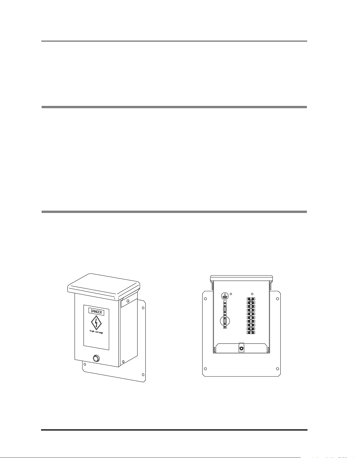
2.1 Application - The CoolPed and CoolPedPLUS AC Power Kit (shown in Fig. 1) allows
AC power to be brought into a CoolPed or CoolPedPLUS Splice Cabinet from an
adjacent power pedestal to provide power for up to four Digital Subscriber Line
Access Modules (DSLAMs) mounted in the cabinet. A fifth AC power circuit can
also be accommodated.
C
a
u
A
t
i
C
o
n
c
:
i
r
c
u
i
t
s
a
r
e
l
i
v
e
.
P
l
e
b
a
r
e
s
e
a
k
e
e
n
r
s
u
f
o
r
r
e
t
t
h
h
e
a
c
t
i
t
r
h
c
u
e
i
t
t
h
b
e
e
"
i
n
O
g
F
w
F
"
i
r
p
e
o
d
s
i
i
s
t
i
o
i
n
n
a
t
t
h
b
e
e
p
f
o
o
r
w
e
e
a
r
n
s
y
o
u
c
o
r
n
c
e
n
e
c
t
i
o
n
s
a
r
e
m
a
d
e
.
front view,
cover removed
Fig. 1 : The CoolPed and CoolPedPLUS AC Power Kit
Outside Plant Equipment Proprietary Information Page 1 of 8
Page 2
631-200-063
round bar
Caution:
AC circuits are live
Please ensure that the
breaker for the circuit being wired is in
the "OFF" position at the power source
before any connections are made
ter
minal
loc
er
Version A, May 2005
Emerson Network Power
Buried Distribution Products
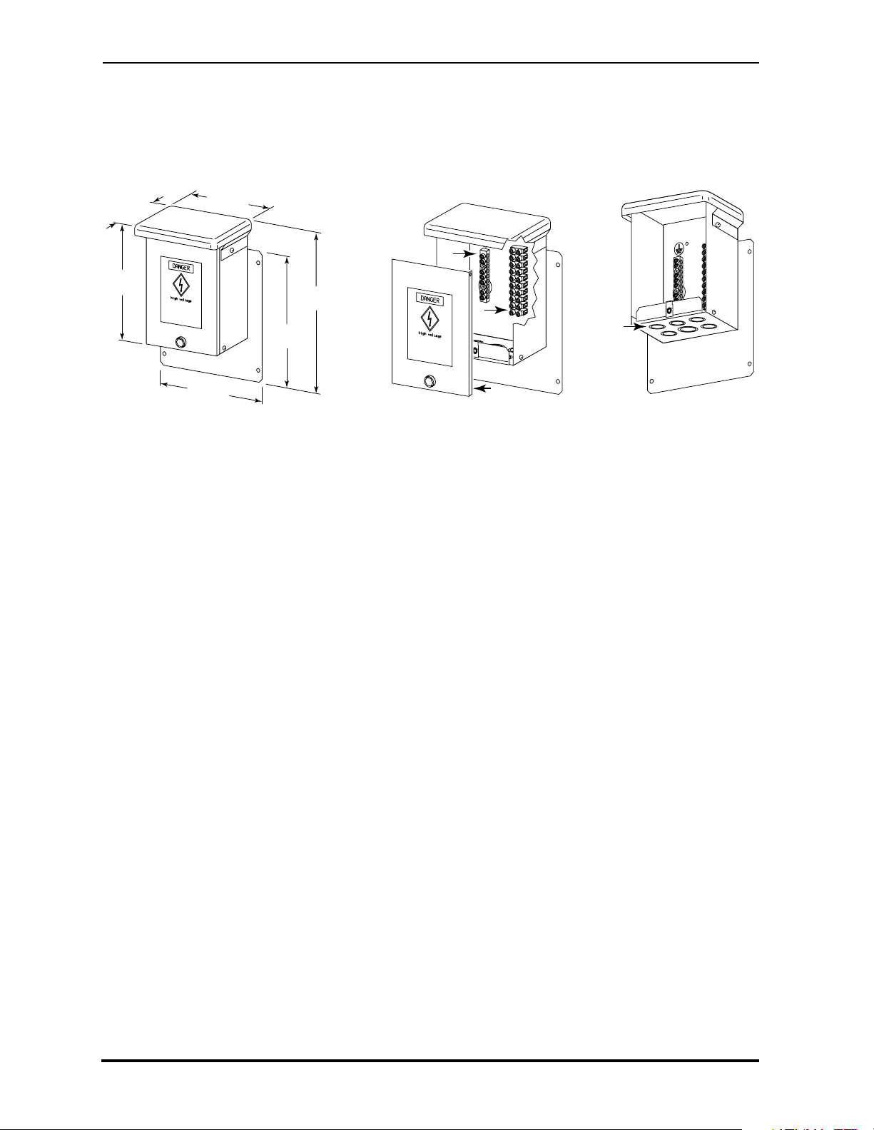
2.2 Physical Specifications - The junction box of the CoolPed and CoolPedPLUS AC
Power Kit is constructed of aluminum. The dimensions are shown in Fig. 2.
i
r
c
u
a
k
"
O
b
e
f
i
t
s
a
e
r
f
o
r
F
F
"
o
r
e
a
C
a
u
t
i
o
r
e
l
i
v
e
.
P
l
e
a
t
h
e
c
i
r
c
u
i
t
p
o
s
i
t
i
o
n
a
t
n
y
c
o
n
n
e
c
t
i
n
:
s
e
e
n
s
u
r
e
t
h
a
t
t
h
e
b
e
i
n
g
w
i
r
e
d
i
s
i
n
t
h
e
p
o
w
e
r
s
o
u
r
c
e
o
n
s
a
r
e
m
a
d
e
.
8.3 inches
(21.1 cm)
6.6 inches
(16.8 cm)
9.0 inches
(22.9 cm)
10.6 inches
(26.9 cm)
ground bar
ground bar
C
C
a
a
u
u
A
t
A
i
t
C
o
i
C
o
n
c
n
:
i
c
:
r
i
c
r
u
c
u
i
t
i
s
t
s
a
a
r
e
r
e
l
i
l
v
i
v
e
e
.
.
P
P
l
e
l
b
e
a
b
r
a
s
r
e
e
s
e
a
e
a
k
e
k
e
n
e
n
e
r
s
r
u
s
f
u
o
f
o
r
r
t
h
t
h
e
e
c
c
i
r
i
r
c
c
u
u
i
t
t
i
h
t
t
b
h
e
b
e
e
e
i
"
n
i
O
"
n
O
g
F
g
F
w
F
w
F
"
"
p
p
o
o
s
s
i
t
i
i
t
o
i
o
n
n
a
a
t
t
t
h
t
h
b
e
b
e
e
p
e
f
p
o
o
f
o
o
r
w
r
e
w
e
e
a
a
n
n
y
y
c
c
o
o
n
n
n
n
e
e
c
c
t
i
t
o
i
o
n
n
s
s
a
a
r
r
e
e
ter
minal
terminal
bloc
block
r
e
r
e
t
h
t
h
a
a
t
t
t
h
t
h
e
e
i
r
i
r
e
e
d
d
i
s
i
s
i
n
i
n
e
r
r
s
s
o
o
u
u
r
r
c
c
e
e
m
m
a
a
d
d
e
e
.
.
k
cocover
cover
Fig. 3 : Features
knockouts
4.4 inches
(11.2 cm)
8.2 inches
(20.8 cm)
A
C
c
b
r
e
t
h
e
Fig. 2 : Junction Box Dimensions
2.3 Features - The junction box of the CoolPed and CoolPedPLUS AC Power Kit is
equipped with the following features (shown in Fig. 3):
• a cover, which is secured with a captive bolt,
• one knockout that accommodates 1-inch (2.5 cm) trade size conduit for the
incoming AC power,
• five knockouts, each of which accommodates a Liquid Tight connector
(supplied) for a DSLAM power cable or other AC power application,
• a seven-position ground bar, and
• a ten-position terminal block.
2.4 Mounting - The junction box of the CoolPed and CoolPedPLUS AC Power Kit
mounts on one of the front mounting rails of a CoolPed or CoolPedPLUS Splice
Cabinet using provided hardware. (See Section 3., Installation on page 3.)
Page 2 of 8 Proprietary Information Outside Plant Equipment
Page 3
Emerson Network Power
Caution:
AC circuits are live
Please ensure that the
breaker for the circuit being wired is in
the "OFF" position at the power source
before any connections are made
Buried Distribution Products
Version A, May 2005
631-200-063
3. INSTALLATION
3.1 You Will Need - To install the CoolPed and CoolPedPLUS AC Power Kit, you will
need:
• a large flathead screwdriver,
• a hammer,
• a 216-type tool, and
• enough 1-inch (2.5 cm) trade-size conduit, connecting hardware, and wiring to
run AC power from the adjacent power pedestal.
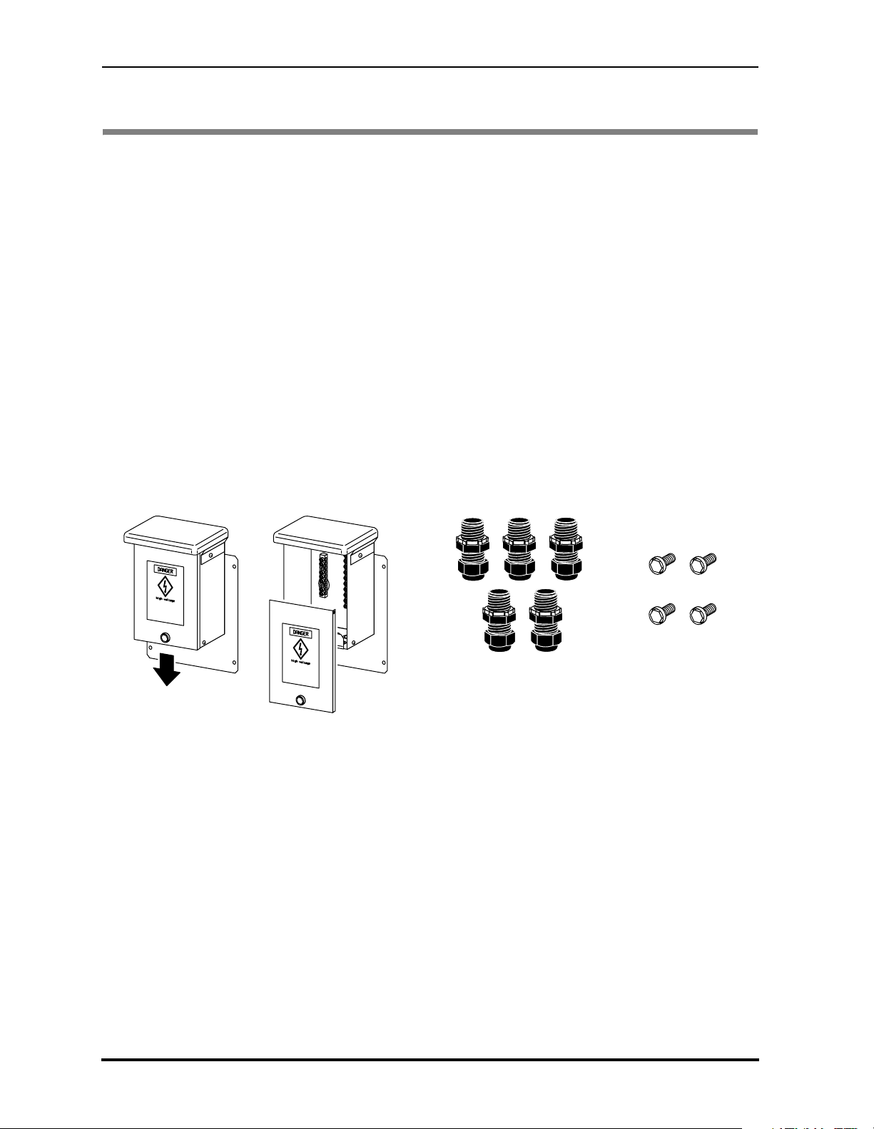
3.2 Checking the Loose Parts Kit - Perform the following steps to verify that the loose
parts kit contains the required hardware:
Step 1: Use a 216-type tool to loosen the
bolt that secures the cover to the junction box, remove the cover (as
shown in Fig. 4), and set the cover safely aside.
Step 2: Remove the loose parts kit packed inside the junction box, and verify
that it contains the required hardware (shown in Fig. 5).
1
/4-20x11/4-inch (3.2 cm long) cup SEMS
C
a
u
tio
A
n
C
:
c
ircu
its
a
re
liv
e
. P
le
a
s
b
e
re
e
a
n
k
su
e
r
re
fo
th
r th
a
t th
e
circu
e
it b
th
e
in
e
"O
g
w
F
ir
F
e
" p
d
is in
o
sitio
n
a
t th
e
p
b
o
e
w
fo
e
r
r
e
so
a
n
u
y
rce
c
o
n
n
e
ct
io
n
s a
re
m
a
d
e.
C
a
u
tio
C
a
A
n
u
C
:
tio
c
A
irc
n
C
:
u
cir
its
cu
a
its
r
e
liv
a
r
e
e
. P
liv
le
e. P
a
s
b
e
le
r
e
e
a
a
n
s
b
k
s
e
r
e
u
e
e
r fo
re
a
n
k
s
th
e
r
u
r fo
th
r
a
e
t th
th
e
r th
circ
a
e
t th
e
u
cir
it b
e
cu
th
e
it b
in
e
"O
g
th
e
w
in
F
e
ire
"O
F
g
w
" p
d
F
is
ir
o
F
sitio
e
in
" p
d
is
o
sitio
n
in
a
t th
n
a
e
t th
p
b
o
e
w
fo
e
p
e
r
b
r
e
o
e
s
a
w
fo
o
n
e
r
u
y
r s
e
rce
a
co
o
n
u
n
y
rce
n
co
e
c
n
tio
n
e
n
c
s
tio
a
re
n
s
m
a
re
a
d
m
e
.
a
d
e
.
5 Liquid Tight
connectors
1
4
/4-20x11/4-inch
(3.2 cm long)
cup SEMS bolts
Fig. 4 : Removing the Junction Box
Fig. 5 : Contents of the Loose Parts Kit
Cover
3.3 Mounting the Junction Box - Perform the following steps to mount the junction
box of the kit in a CoolPed or CoolPedPLUS Splice Cabinet:
Step 1: Use a hammer and a large flathead screwdriver to remove the knockout
for the incoming AC power conduit (shown in Fig. 6).
Outside Plant Equipment Proprietary Information Page 3 of 8
Page 4

631-200-063
Version A, May 2005
knockouts for
knockouts for
DSLAM power
DSLAM power
cables
cables
Buried Distribution Products
knockout for
knockout for
incoming AC
incoming AC
power conduit
power conduit
knockouts for
knockouts for
DSLAM power
DSLAM power
cables
cables
Emerson Network Power
Fig. 6 : Knockouts
Step 2: As required, remove knockouts for the DSLAM power cables or other AC
power applications (shown in Fig. 6).
ALERT
Do not remove knockouts that you will not be using.
Step 3: On the bottom of the junction box, attach one of the supplied Liquid
Tight connectors to each of the smaller holes that you will be using for
DSLAM power cables or other AC power applications (as shown in
Fig. 7).
Page 4 of 8 Proprietary Information Outside Plant Equipment
Page 5

Emerson Network Power
Buried Distribution Products
631-200-063
Version A, May 2005
Fig. 7 : Attaching a Liquid Tight Connector
Step 4: Connect the DSLAM power cables (or other AC power cables) to the
Liquid Tight connectors per local practices. (See Fig. 8.)
Step 5: Use a a 216-type tool and the four cup SEMS bolts to mount the junction
box on the lower mounting rails of the CoolPed or CoolPedPLUS Splice
Cabinet, in the center position (as shown in Fig. 9).
Fig. 8 : Connecting a DSLAM
Power Cable to the Junction Box
lower mounting rails
of CoolPed or
CoolPedPLUS
Splice Cabinet
Fig. 9 : Mounting the Junction Box in the CoolPed or CoolPedPLUS Splice Cabinet
Outside Plant Equipment Proprietary Information Page 5 of 8
Page 6

631-200-063
ter
minal
loc
round
bar
Caution:
AC circuits are live
Please ensure that the
breaker for the circuit being wired is in
the "OFF" position at the power source
before any connections are made
Version A, May 2005
Step 6: Per local practices, install a run of 1-inch (2.5 cm) trade size conduit from
Step 7: Per local practices, connect the wiring for the incoming AC power and for
ground
ground
bar
bar
ter
minal
terminal
bloc
k
block
Emerson Network Power
Buried Distribution Products
the adjacent power pedestal to the large hole on the bottom of the
junction box for the incoming AC power (shown in Fig. 6), and run wiring
from the adjacent power pedestal.
the DSLAMs (and other AC power applications) to the junction box’s
terminal block and ground bar (shown in Fig. 10).
:
n
o
i
t
u
e
a
h
t
C
t
a
h
t
e
r
u
s
n
e
e
s
a
e
l
P
.
e
n
i
v
i
l
s
i
e
r
d
e
a
r
s
i
t
i
w
u
g
c
r
n
i
i
c
e
b
C
t
i
A
u
c
r
i
e
c
c
r
e
u
h
t
o
s
r
o
r
f
e
r
w
e
o
k
p
a
e
e
r
h
t
b
t
a
n
o
i
t
i
.
s
e
o
d
p
a
"
m
F
F
e
r
O
a
"
s
e
n
h
o
t
i
t
c
e
n
n
o
c
y
n
a
e
r
o
f
e
b
:
:
n
tion
o
i
u
e
t
a
u
e
C
a
h
t th
C
t
a
t
a
h
t
re th
e
r
su
u
s
n
en
e
se
e
a
s
a
le
e
l
. P
e
. P
e
n
v
i
i
l
is in
is
re liv
d
e
r
d
e
ire
a
r
s
its a
i
t
w
i
g
w
u
g
c
r
n
ein
i
i
circu
c
e
C
b
C
it b
A
t
i
A
u
c
r
i
circu
e
e
rce
c
c
e
r
h
u
o
t
r
s
o
er sou
r
f
r for th
e
w
r
e
o
w
e
k
o
k
a
p
e p
rea
e
e
r
b
h
b
t
t th
t
a
a
n
n
o
i
itio
it
.
e.
s
os
e
o
d
d
a
" p
p
a
"
F
F
m
F
F
e
re m
r
O
a
"O
a
"
s
e
s
e
n
h
th
t
o
i
t
ction
c
e
e
n
n
n
n
o
co
c
y
y
n
n
a
e
re a
r
o
fo
f
e
e
b
b
Fig. 10 : The Terminal Block
and Ground Bar
Step 8: When you have completed the wiring, replace the junction box’s cover (as
shown in Fig. 11), and secure it by using a 216-type tool to tighten the
cover’s cup SEMS bolt.
Fig. 11 : Securing the Junction Box Cover
Page 6 of 8 Proprietary Information Outside Plant Equipment
Page 7

Emerson Network Power
Buried Distribution Products
631-200-063
Version A, May 2005
NOTES
Outside Plant Equipment Proprietary Information Page 7 of 8
Page 8

631-200-063
Version A, May 2005
Part No. 128048
Emerson Network Power
Buried Distribution Products
NOTES
Emerson Network Power / 4350 Weaver Parkway / Warrenville, Illinois 60555 / (630) 579-5000 / FAX (630) 579-5050
© 2005 Emerson Network Power, Energy Systems, North America, Inc.
All rights reserved. Any unauthorized reproduction or transmission
without the prior consent of Emerson Network Power is prohibited.
www.gotoemerson.com
Specifications subject to change without notice. Emerson Network Power, Energy Systems, North America, Inc. disclaims any responsibility or liability for the use of the information contained in this practice.
Printed in the USA Page 8 of 8
 Loading...